
Loading ...
Loading ...
Loading ...
Guards and Flanges
It is important to choose the correct guards and flanges to use with
the grinder accessories. See the Accessories Chart for the correct
accessories.
NOTE: Edge grinding and cutting can be performed with Type 27
wheels designed and specified for this purpose.
WARNING: Accessories must be rated for at least the speed
recom mended on the tool warning label. Wheels and other
accessories running over rated accessory speed may burst and
cause injury. Every unthreaded accessory must have a 7/8" arbor
hole. If it does not, it may have been designed for a circular saw and
should not be used. Use only the accessories shown in the
Accessories Chart of this manual. Accessory ratings must be
above listed minimum wheel speed as shown on tool nameplate.
Switches
CAUTION: Hold the side handle and body of the tool firmly to
maintain control of the tool at start up and during use and until the
wheel or accessory stops rotating. Make sure the wheel has come to
a complete stop be fore laying the tool down.
NOTE: To reduce unexpected tool movement, do not switch the
tool on or off while under load conditions. Allow the grinder to run
up to full speed before touching the work surface. Lift the tool from
the surface before turning the tool off. Allow the tool to stop rotating
before putting it down.
PADDLE SWITCH (DWE4120, DWE4120N) (FIG. 6)
CAUTION: Before connecting the tool to a power source depress
and release the paddle switch (H) to ensure that the switch is off..
Depress and release the paddle switch as described above after any
interruption in power supply to the tool, such as the activation of a
ground fault interrupter, throwing of a circuit breaker, accidental
unplugging, or power failure.
2. Align the lugs (L) on the guard with the slots on the gear case (M).
3. Push the guard down until the guard lugs engage and rotate them
in the groove on the gear case hub. Release the guard release
lever.
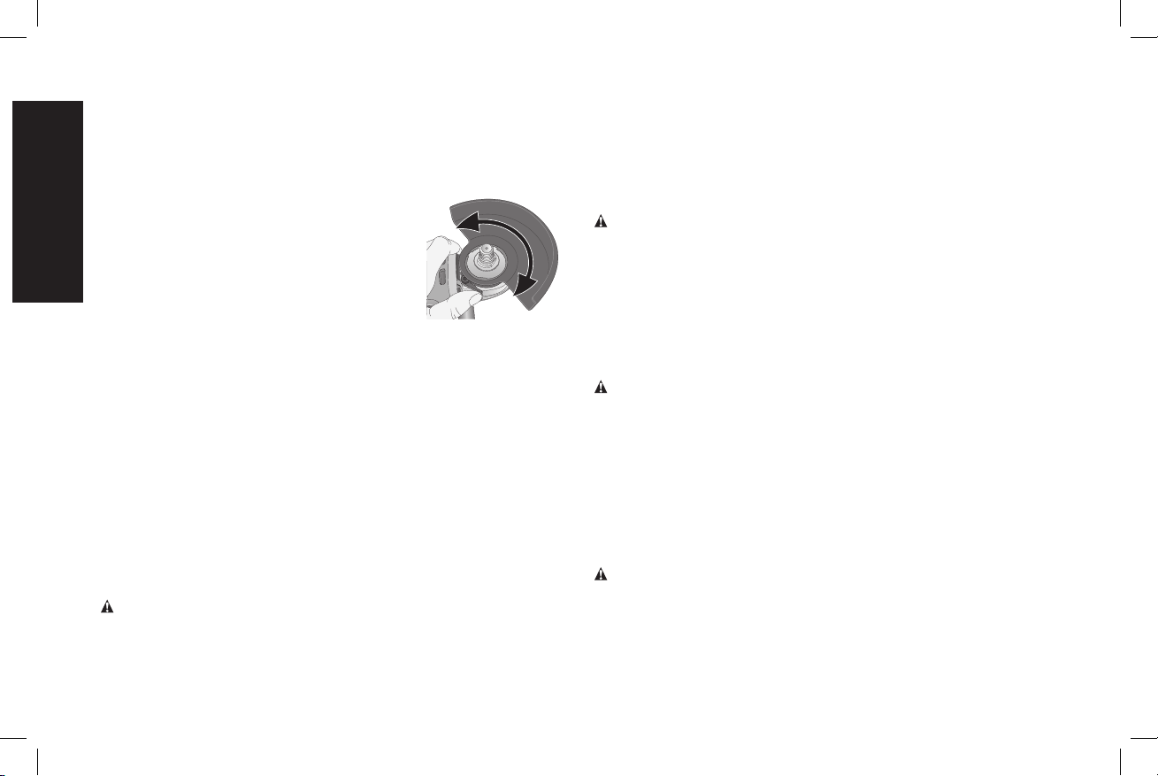
4. With the spindle facing the operator, rotate
FIG. 5
the guard clockwise into the desired
working position. The guard body should
be positioned between the spindle and
the operator to provide maximum operator
protection.
5. For easy adjustment, the guard can be
rotated in the clockwise direction. NOTE:
The guard release lever should snap into
one of the alignment holes (N) on the
guard collar. This insures that the guard is secure. The guard can
be repositioned the opposite direction by depressing the guard
release lever.
6. To remove the guard, follow steps 1–3 of these instructions in
reverse.
NOTE: Edge grinding and cutting can be performed with Type 27
wheels designed and specified for this purpose; 1/4" (6.35mm) thick
wheels are designed for surface grinding while 1/8" (3.17 mm) wheels
are designed for edge grinding. Cutting can also be performed by
using a Type 1 wheel and a Type 1 guard.
NOTE: See the Accessories Chart to select the proper guard /
accessory combination.
OPERATION
WARNING: To reduce the risk of injury, turn unit off and
disconnect it from power source before installing and removing
accessories, before adjusting or when making repairs. An
accidental start-up can cause injury.
English
10
Loading ...
Loading ...
Loading ...