Home
Bookmarks
Home
JET
JET GH-1440-3 User Manual
Page 61
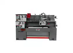
JET GH-1440-3 Geared Head Lathe
Manual - Page 61
For GH-1440-3.
PDF File Manual
,
68 pages
,
Read Online
|
Download pdf file
Geared Head Lathe 14x40 inch
1.0 IMPORTANT SAFETY INSTRUCTIONS
2.0 Table of contents
3.0 About this manual
4.0 Specifications
4.1 Cross Slide T-slot dimensions
5.0 Uncrating
5.1 Contents of shipping container
6.0 Installation
6.1 Chuck preparation (three jaw)
7.0 Lubrication
8.0 Coolant preparation
9.0 Electrical connections
9.1 Voltage conversion (GH-1440-3 only)
10.0 General description
11.0 Operation
11.1 Break-in procedure
11.2 Feed and thread selection
11.3 Change gears replacement
11.4 Automatic feed operation and feed changes
11.5 Powered carriage travel
11.6 Thread cutting
11.7 Compound rest
12.0 Adjustments
12.1 Saddle
12.2 Cross slide
12.3 Compound rest
12.4 Tailstock
12.5 Tailstock off-set
12.6 Tailstock gibs
12.7 Headstock alignment
12.8 Removing gap bridge
12.9 Installing gap bridge
12.10 Belt replacement and adjustment
12.11 Aligning tailstock to headstock
13.0 Operation tables
14.0 Replacement Parts
14.1.1 Headstock Assembly I â Exploded View
14.1.2 Headstock Assembly I â Parts List
14.2.1 Headstock Assembly II â Exploded View
14.2.2 Headstock Assembly II â Parts List
14.3.1 Headstock Assembly III â Exploded View
14.3.2 Headstock Assembly III â Parts List
14.4.1 Gearbox Assembly I â Exploded View
14.4.2 Gearbox Assembly I â Parts List
14.5.1 Gearbox Assembly II â Exploded View
14.5.2 Gearbox Assembly II â Parts List
14.6.1 Apron Assembly I â Exploded View
14.6.2 Apron Assembly I â Parts List
14.7.1 Apron Assembly II â Exploded View
14.8.1 Saddle and Cross Slide Assembly â Exploded View
14.8.2 Saddle and Cross Slide Assembly â Parts List
14.9.1 Top Slide and Tool Post â Exploded View
14.9.2 Top Slide and Tool Post â Parts List
14.10.1 Tailstock Assembly â Exploded View
14.10.2 Tailstock Assembly â Parts List
14.11.1 Bed and Shaft Assembly â Exploded View
14.11.2 Bed and Shaft Assembly â Parts List
14.12.1 Stand and Brake Assembly â Exploded View
14.12.2 Stand and Brake Assembly â Parts List
14.13.1 End Gear Assembly â Exploded View
14.13.2 End Gear Assembly â Parts List
14.14.1 Follow Rest â Exploded View
14.14.2 Follow Rest â Parts List
14.15.1 Thread Dial Assembly â Exploded View
14.15.2 Thread Dial Assembly â Parts List
14.16.1 Steady Rest â Parts List
14.16.2 Steady Rest â Parts List
14.17.1 Coolant and Work Light Assembly â Exploded View
14.17.2 Coolant and Work Light Assembly â Parts List
14.18.1 Chuck Guard Assembly â Exploded View
14.18.2 Chuck Guard Assembly â Parts List
14.19.1 Lead Screw Cover Assembly â Exploded View
14.19.2 Lead Screw Cover Assembly â Parts List
14.20.1 Accessories I â Exploded View
14.20.2 Accessories I â Parts List
14.21.1 Accessories II â Exploded View
14.21.2 Accessories II â Parts List
14.22.1 Electrical Components â Exploded View
14.22.2 Electrical Components â Parts List
15.0 Electrical Connections
15.1 Wiring Diagram â 1 Phase
15.2 Wiring Diagram â 3 Phase
16.0 Warranty and service
Page 61/68
Page 1
Page 2
Page 3
Page 4
Page 5
Page 6
Page 7
Page 8
Page 9
Page 10
Page 11
Page 12
Page 13
Page 14
Page 15
Page 16
Page 17
Page 18
Page 19
Page 20
Page 21
Page 22
Page 23
Page 24
Page 25
Page 26
Page 27
Page 28
Page 29
Page 30
Page 31
Page 32
Page 33
Page 34
Page 35
Page 36
Page 37
Page 38
Page 39
Page 40
Page 41
Page 42
Page 43
Page 44
Page 45
Page 46
Page 47
Page 48
Page 49
Page 50
Page 51
Page 52
Page 53
Page 54
Page 55
Page 56
Page 57
Page 58
Page 59
Page 60
Page 61
Page 62
Page 63
Page 64
Page 65
Page 66
Page 67
Page 68
Contents
Table of Contents
Search
Previous
Next
Bookmarks
Loading ...
Loading ...
Loading ...
61
14.20.1
A
ccessories I – Exploded Vie
w
Loading ...
Loading ...
Loading ...
File type: PDF
File name: 25755707_gh-1440-1.pdf
File size: 2.02 MB
File Language: English
Pages: 68
Author: JET
File created: 2018-08-13
Published:
2023-04-18
Updated: 2023-09-01
Download File
Table of Contents
×
Geared Head Lathe 14x40 inch
1
1.0 IMPORTANT SAFETY INSTRUCTIONS
2
2.0 Table of contents
4
3.0 About this manual
5
4.0 Specifications
6
4.1 Cross Slide T-slot dimensions
7
5.0 Uncrating
8
5.1 Contents of shipping container
8
6.0 Installation
9
6.1 Chuck preparation (three jaw)
9
7.0 Lubrication
10
8.0 Coolant preparation
12
9.0 Electrical connections
12
9.1 Voltage conversion (GH-1440-3 only)
12
10.0 General description
13
11.0 Operation
16
11.1 Break-in procedure
16
11.2 Feed and thread selection
17
11.3 Change gears replacement
17
11.4 Automatic feed operation and feed changes
17
11.5 Powered carriage travel
18
11.6 Thread cutting
18
11.7 Compound rest
18
12.0 Adjustments
18
12.1 Saddle
18
12.2 Cross slide
19
12.3 Compound rest
19
12.4 Tailstock
19
12.5 Tailstock off-set
19
12.6 Tailstock gibs
19
12.7 Headstock alignment
20
12.8 Removing gap bridge
20
12.9 Installing gap bridge
20
12.10 Belt replacement and adjustment
21
12.11 Aligning tailstock to headstock
21
13.0 Operation tables
22
14.0 Replacement Parts
22
14.1.1 Headstock Assembly I â Exploded View
23
14.1.2 Headstock Assembly I â Parts List
24
14.2.1 Headstock Assembly II â Exploded View
26
14.2.2 Headstock Assembly II â Parts List
27
14.3.1 Headstock Assembly III â Exploded View
28
14.3.2 Headstock Assembly III â Parts List
29
14.4.1 Gearbox Assembly I â Exploded View
30
14.4.2 Gearbox Assembly I â Parts List
31
14.5.1 Gearbox Assembly II â Exploded View
33
14.5.2 Gearbox Assembly II â Parts List
34
14.6.1 Apron Assembly I â Exploded View
36
14.6.2 Apron Assembly I â Parts List
37
14.7.1 Apron Assembly II â Exploded View
38
14.8.1 Saddle and Cross Slide Assembly â Exploded View
40
14.8.2 Saddle and Cross Slide Assembly â Parts List
41
14.9.1 Top Slide and Tool Post â Exploded View
43
14.9.2 Top Slide and Tool Post â Parts List
44
14.10.1 Tailstock Assembly â Exploded View
45
14.10.2 Tailstock Assembly â Parts List
46
14.11.1 Bed and Shaft Assembly â Exploded View
47
14.11.2 Bed and Shaft Assembly â Parts List
48
14.12.1 Stand and Brake Assembly â Exploded View
50
14.12.2 Stand and Brake Assembly â Parts List
51
14.13.1 End Gear Assembly â Exploded View
52
14.13.2 End Gear Assembly â Parts List
53
14.14.1 Follow Rest â Exploded View
54
14.14.2 Follow Rest â Parts List
54
14.15.1 Thread Dial Assembly â Exploded View
55
14.15.2 Thread Dial Assembly â Parts List
55
14.16.1 Steady Rest â Parts List
56
14.16.2 Steady Rest â Parts List
57
14.17.1 Coolant and Work Light Assembly â Exploded View
58
14.17.2 Coolant and Work Light Assembly â Parts List
58
14.18.1 Chuck Guard Assembly â Exploded View
59
14.18.2 Chuck Guard Assembly â Parts List
59
14.19.1 Lead Screw Cover Assembly â Exploded View
60
14.19.2 Lead Screw Cover Assembly â Parts List
60
14.20.1 Accessories I â Exploded View
61
14.20.2 Accessories I â Parts List
62
14.21.1 Accessories II â Exploded View
63
14.21.2 Accessories II â Parts List
63
14.22.1 Electrical Components â Exploded View
64
14.22.2 Electrical Components â Parts List
64
15.0 Electrical Connections
65
15.1 Wiring Diagram â 1 Phase
65
15.2 Wiring Diagram â 3 Phase
66
16.0 Warranty and service
67
Search:
×
Search