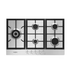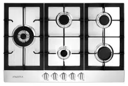
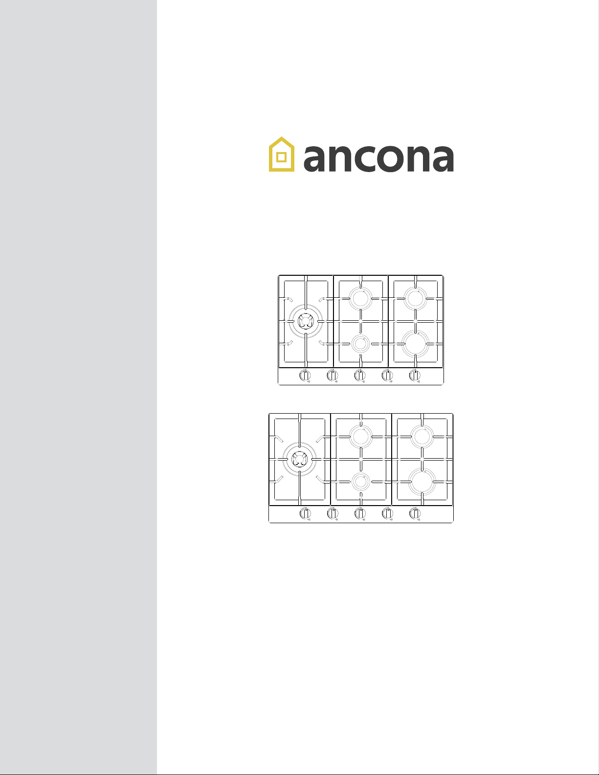
Gas Cooktop
User Manual
and
Installation Instructions
IMPORTANT SAFETY INSTRUCTIONS
Carefully read the important information
regarding installation, safety and maintenance.
Keep these instructions for future reference.
MAAN2125-02
2023-02-12
AN-2125 / AN-2126
— 2 —
INSTALLERS - Start Here
Safety Instructions are on pages 4 to 6 and
Installation Instructions are on pages 7 to 18.
Please perform these steps:
1. Read the safety instructions.
2. Read all instructions in the Installation section of this
manual BEFORE installing the appliance.
3. Remove all packing materials.
4. Observe all governing codes and ordinances.
5. When nished, make sure to leave these instructions with the consumer.
6. Installation is only to be done by a qualied technician, but ultimately proper
installation is the responsibility of the installer.
7. Product failure due to improper installation is not covered under the Warranty.
CONSUMERS - Start Here
Safety Instructions are on pages 4 to 6 and
Operating Instructions are on pages 19 to 23.
Please perform these steps:
1. Read the safety instructions.
2. Read all instructions in the manual BEFORE
operating the appliance.
3. Remove all packing materials before using.
4. Observe all governing codes and ordinances.
5. Installation is only to be done by a qualied technician, but ultimately proper
installation is the responsibility of the installer.
6. Product failure due to improper installation is not covered under the Warranty.
Before You Begin

— 3 —
Before You Begin ..................................................................................................................................... 2
Table of Contents .................................................................................................................................... 3
Important Safety Information .................................................................................................................. 4
Installation ............................................................................................................................................... 7
Getting Started .................................................................................................................................. 7
Liqueed Petroleum (Propane) Gas Conversion ............................................................................... 7
Included Parts ................................................................................................................................... 8
Tools and Additional Parts Needed ................................................................................................... 9
Dimensions ..................................................................................................................................... 10
Advance Preparation ....................................................................................................................... 11
Step 1 - Read the Safety Precautions ............................................................................................. 12
Step 2 - Plan Desired Location, Unpack the Appliance and Prepare Tools .................................... 12
Step 3 - Cutting the Countertop ..................................................................................................... 12
Step 4 - Installing Cooktop ............................................................................................................. 12
Step 5 - Installing the Pressure Regulator ...................................................................................... 13
Step 6 - Electrical Connection ........................................................................................................ 14
Step 7 - Assembling the Burners .................................................................................................... 15
Step 8 (Optional) - Liqueed Petroleum (Propane) Gas Conversion ............................................... 16
Adjusting the Regulator Pressure ...................................................................................... 17
Changing Burner Nozzles .................................................................................................. 17
Adjust Burner Flames ........................................................................................................ 18
Testing Flame Stability ....................................................................................................... 18
Flame Re-Check ................................................................................................................ 18
Operation ............................................................................................................................................... 19
Flame Size ....................................................................................................................................... 19
Proper Burner Adjustments ............................................................................................................ 19
Location of the Burners .................................................................................................................. 19
Placement of Burner Heads and Caps ........................................................................................... 20
Surface Cooking Utensils ................................................................................................................ 20
Setting Surface Controls ................................................................................................................. 21
To Operate the Surface Burners ..................................................................................................... 21
Knob Symbols ................................................................................................................................. 21
Lighting the Burners ........................................................................................................................ 21
Care and Cleaning ................................................................................................................................. 22
Troubleshooting Tips ............................................................................................................................. 22
Table of Contents
— 4 —
Important Safety Information
READ ALL INSTRUCTIONS BEFORE USE
Read and follow all instructions before using your oven to prevent the risk of re, electric shock, personal
injury, or damage when using the appliance. This guide does not cover all possible conditions that may occur.
Always contact your service technician or manufacturer about problems that you do not understand.
DANGER: When you see this symbol in the instructions, it indicates a hazardous
situation which, if not avoided, could result in death or serious injury.
WARNING: When you see this symbol in the instructions, it indicates a hazardous
situation which, if not avoided, could result in minor or moderate injury.
WHAT TO DO IF YOU SMELL GAS
•Openallwindowsstartingwiththoseclosesttotheappliance.
•DONOTtrytolightanyappliance.
•DONOTtouchanyelectricalswitchoroutlet.
•DONOTuseanyphoneinyourhome/building.
•Immediatelycallyourgassupplierfromaneighbor’sphone.Followthegassupplier’sinstructions.
•Ifyoucannotreachyourgassupplier,calltheredepartment.
INSTALLATION
•Removealltapeandpackagingbeforeusingtheappliance.Neverallowchildrentoplaywithpackagingmaterial.
•Dispose the carton and plastic bags after the appliance is unpacked. Cartons covered with rugs, bedspreads, or plastic
sheets can become air-tight chambers.
•Remove all staples from the carton. Staples can cause severe cuts and destroy nishes if they come in contact with
other appliances or furniture.
•Donotremovethemodel/serialplateattachedtotheappliance.
•
Be sure your appliance is properly installed and grounded by a QUALIFIED TECHNICIAN in accordance with the
National Fuel Gas Code ANSI Z223.1—latest edition in the United States, or in Canada CAN/CGA B149.1, and CAN/
CGA B149.2, and the National Electrical Code ANSI/NFPA No. 70—latest edition in United States, or in Canada
CSA Standard C22.1, Canadian Electrical Code, Part 1, and local code requirements. Install only as per installation
instructions provided in the literature package for this cooktop.

— 5 —
Important Safety Information
WARNINGS
•Donotstoreorusegasoline,liquidpropanecylinderor
other ammable vapors and liquids in the vicinity of this
or any other appliance.
•Gasleakscannotalwaysbedetectedbysmell.
•Gassuppliersrecommendthatyouuseagasdetector
approved by UL or CSA. For more information, contact
your gas supplier.
•Installationandservicemustbeperformedbyaqualied
installer, servicer or the gas supplier. Ask your dealer
to recommend a qualied technician and an authorized
repair service. Know how to shut off gas supply at
the meter and disconnect the electrical power to the
appliance at the circuit breaker or fuse box in case of an
emergency. Have the installer show you the location of
the appliance gas shut-off valve and how to shut it off
if necessary.
•Donotrepairorreplaceanypartoftheapplianceunless
specically recommended in this manual. All other
servicing should be done only by a qualied technician.
This may reduce the risk of personal injury and damage
to the appliance.
•If the information in this manual is not followed
exactly, a re or explosion may result causing
property damage, personal injury or death.
•Disconnectpowerbeforeservicing.
•Nevermodifyoraltertheconstructionoftheappliance
by removing panels, wire covers or any other part of
the product.
•Overheadrangehoods,whichoperatebyblowinga
downward air ow on to the appliance, shall not be used
in conjunction with gas appliances other than when
the hood and appliance have been designed, tested
and listed by an independent test laboratory for use in
combination with each other.
•Ifapplianceislocatednearawindow,NEVERhanglong
curtains or paper blinds on that window. They could
blow over the surface burners and ignite, causing a
re hazard.
•Ensurethattheroomiswellventilatedbykeepingtheair
intakes open and in good working order or by installing
an extractor hood with discharge pipe. If the appliance
is used intensively for a long time the effectiveness of
the ventilation will have to be increased, for example
by opening a window or increasing the power of any
electric extractor fan.
•Flammablematerialsshouldnotbestoredonthe
appliance or near surface units. This includes paper,
plastic and cloth items, such as cookbooks, plastic
ware and towels, as well as ammable liquids. Do not
store explosives, such as aerosol cans, on or near the
appliance. Flammable materials may explode and result
in re or property damage.
•Maintenance: Keep appliance area clear and free from
combustible materials, gasoline, and other ammable
vapors and liquids.
•Storage in or on the appliance: Flammable materials
should not be stored on or near surface units.
•Donotstoreitemsofinteresttochildreninthecabinets
above the appliance. Children should not be left alone
or unattended in the area where appliance is in use. Do
not allow children to climb or play around the appliance.
They should never be allowed to sit or stand on any part
of the appliance. Children climbing on the appliance to
reach items could be seriously injured.
•DONOTTOUCHTHECOOKINGSURFACE,THE
BURNERS, GRATES, OR ANY AREAS NEAR THEM.
Surface burners or appliance may be hot even though
ames are not visible. Areas near surface burners or
appliance may become hot enough to cause burns.
During and after use, do not touch, or let clothing or
other ammable materials touch these areas until they
have had sufcient time to cool. Among these areas are
the cooktop and surfaces facing the cooktop.
•Donotwearloose-ttingorhanginggarmentswhile
using the appliance. Do not let clothing or other
ammable materials contact hot surfaces.
•Smothergreasereswithapanlid,orusebakingsoda,
a dry chemical or foam-type extinguisher.
•UseanextinguisherONLYif:
- You know you have a Class A, B or C extinguisher, and
you already know how to operate it.
- The re is small and contained in the area where it
is started.
- The re department is being/has been called.
- You can ght the re with your back to an exit.
•Whenheatingfatorgrease,watchitclosely.Fator
grease may catch re if allowed to become too hot.
•Useonlydrypotholders.Moistordamppotholderson
hot surfaces may result in burns from steam. Do not
let potholders touch hot heating elements, the ame or
burners. Do not use a towel or other bulky cloth instead
of a potholder.

— 6 —
Important Safety Information
•Donotheatunopenedfoodcontainers.Buildupof
pressure may cause the container to burst and result
in injury.
•Stepping,leaningorsittingonthisappliancecanresultin
serious injuries and also cause damage to the appliance.
•Never use this appliance as a space heater to heat
or warm the room. Doing so may result in carbon
monoxide poisoning and overheating.
•Knowwhichknobcontrolswhichsurfaceburner.Visually
check that the burner has lit. Then adjust the ame so it
does not extend beyond the edge of the pot/pan.
•Cleantheapplianceregularlytokeepallpartsfreeof
grease that could catch re. Exhaust fan ventilation
hoods and grease lters should be kept clean. Do not
allow grease to accumulate on hood or lter. Greasy
deposits in the fan could catch re. When cooking food,
turnthehoodfanon.Refertohoodmanufacturer’s
instructions for cleaning.
•
Pot/pan handles should be turned inward and not
extend over adjacent surface burners. To reduce the
risk of burns, ignition of ammable materials, and
spillage due to unintentional contact with the pot/pan,
the handle of the utensil should be positioned so that
it is turned inward, and does not extend over adjacent
surface burners.
•Neverleavesurfaceburnersunattendedathighheat
settings. Boilovers cause smoke and greasy spillovers
that may ignite, or a pan that has boiled dry may melt.
•Donotusealuminumfoiltolineanypartofthe
appliance. Use aluminum foil only to cover food during
cooking. Improper installation of these liners may result
in risk of electric shock or re.
•Onlycertaintypesofglass,glass/ceramic,ceramic,
earthenware, or other glazed utensils are suitable for
cooktop service without breaking due to the sudden
changeintemperature.Checkthemanufacturer’s
recommendations for cooktop use.
•Donotusedecorativesurfaceburnercovers.Ifa
burner is accidentally turned on, the decorative cover
will become hot and possibly melt. You will not be able
to see that the burner is on. Burns will occur if the hot
covers are touched. Damage may also be done to the
cooktop or burners because the covers may cause
overheating. Air will be blocked from the burner and
cause combustion problems.
•Alwaysuseproperamesize.Adjustamesizesoit
does not extend beyond the edge of the pot/pan. The
use of undersized pots/pans will expose a portion of the
burner ame to direct contact and may result in ignition
of clothing. Proper relationship of pot/pan to ame will
also improve efciency.
•Topburneramesizeshouldbeadjustedsoitdoesnot
extend beyond the edge of the cooking utensil.
•Usetheproperpot/pansizes.Thisapplianceisequipped
with surface units of different sizes. Select pots/pans
having at bottoms large enough to cover the surface
unit. The use of undersized utensils will expose a portion
of the surface heating unit to direct contact and may
result in ignition of clothing. Proper relationship of utensil
to the surface unit will also improve efciency.
•Donotusestovetopgrillsonyourgasappliance.If
you use a stove top grill on a sealed gas burner, it will
cause incomplete combustion and can result in exposure
to carbon monoxide levels above allowable current
standards. This can be hazardous to your health.
•Removeallpackagingmaterialsfromtheappliance
before operating it. These materials can ignite, causing
smoke and/or re damage.
— 7 —
Installation
Getting Started
•This cooktop features a pilotless electric ignition for energy savings
and reliability. It operates on a 120-volt, 60 Hz power supply. A
separate circuit, protected by a 15-amp time delay fuse or circuit
breaker, is required.
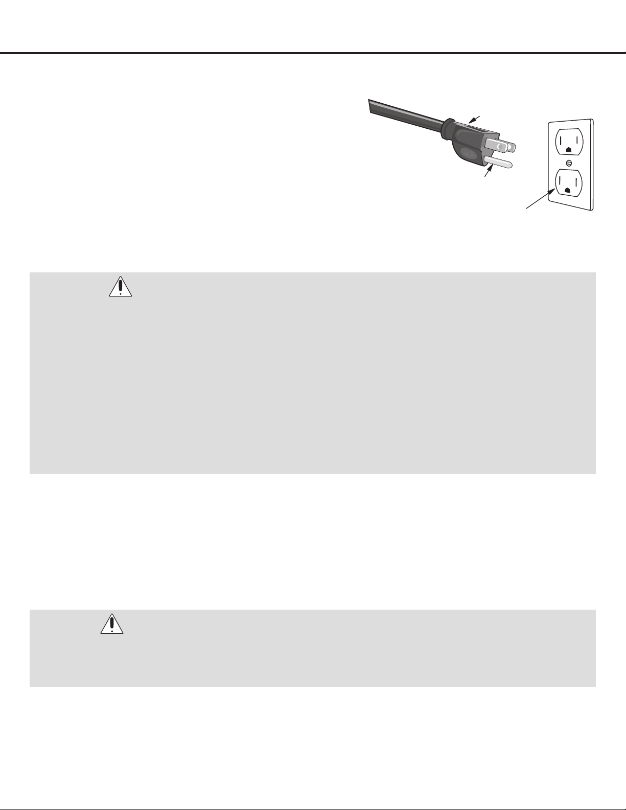
•For personal safety, the cooktop must be properly grounded. A
properly grounded 3-prong receptacle (see Figure 1) should be
located12”belowthecountertopandwithinreachofthecooktop’s
four-foot power cord.
•For maximum safety, the power cord must be plugged into an
electrical outlet that is correctly polarized and properly grounded.
•See the Installation Instructions packaged with this cooktop for
complete installation and grounding instructions.
Liqueed Petroleum (Propane) Gas Conversion
•This appliance can be used with Natural Gas and Propane (LP) Gas. It is shipped from the factory for use with natural
gas.
•A kit for converting to LP gas is supplied with your cooktop. The kit is marked “FOR LP/ PROPANE GAS
CONVERSION”.Forconversion,followtheinstallationinstructionswhichareinthismanual.
WARNING:
The conversion must be performed by a qualified service technician in accordance with the kit instructions and all
local codes and requirements. Failure to follow instructions could result in serious injury or property damage. The
qualified agency performing this work assumes responsibility for the conversion.
WARNINGS:
•DO NOT operate the cooktop using a 2-prong adapter or an extension cord. If a 2-prong wall receptacle is the only
available outlet, it is the personal responsibility of the consumer to have it replaced with a properly grounded 3-prong
wall receptacle installed by a qualified electrician.
•Thisapplianceisequippedwitha3-pronggroundingplugforyourprotectionagainstshockhazardandshouldbe
plugged directly into a properly grounded receptacle. To avoid fire hazard or electrical shock, DO NOT cut or remove
the grounding prong from this plug and DO NOT use an adapter plug, an extension cord, or remove grounding prong
from electrical power cord. Failure to follow this warning can cause serious injury, fire or death.
•Severeshock,ordamagetothecooktopmayoccurifthecooktopisnotinstalledbyaqualifiedinstalleror
electrician.
•Anyadditions,changesorconversionsrequiredinorderforthisappliancetosatisfactorilymeettheapplicationneeds
mustbemadebyaqualifiedservicetechnicianinaccordancewiththemanufacturer’sinstructionsandallcodes
and requirements of the authority having jurisdiction. Failure to follow the instructions could result in serious injury or
property damage. The qualified agency performing this work assumes responsibility for the conversion.
3-Pronged Plug
Ground Plug
Grounded outlet
Figure 1
— 8 —
Installation
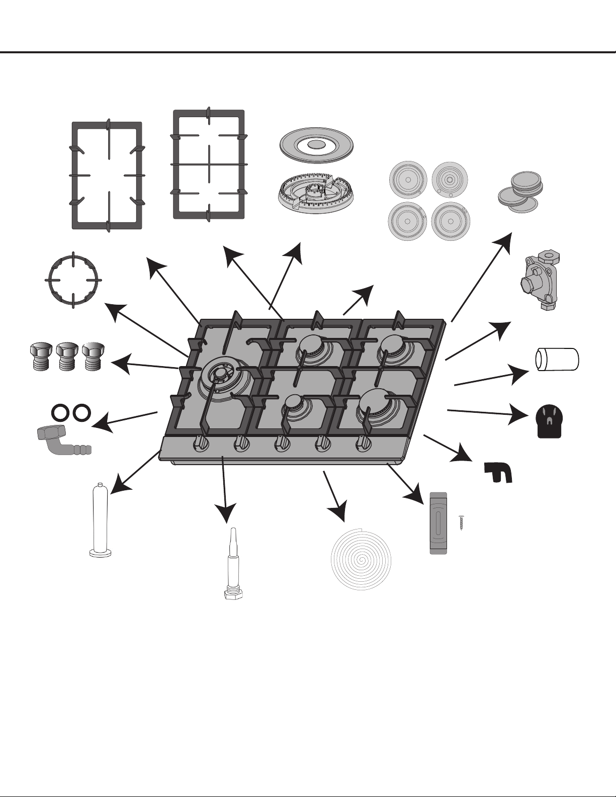
Included Parts
2 × Grates
1 × Triple Ring Grate
1 × Triple Ring
Pan Support
5 × LPG Nozzles
1 × Triple Ring Igniter
4 × Igniter
1 × Fitting
1 × Triple Ring Thermocouple
4 × Thermocouple
1 × Foam Gasket
1 × Regulator
1 × 7 mm
Nut Driver
1 × Triple Ring Burner
2 × Semi-Rapid Burner
1 × Auxiliary Burner
1 × Rapid Burner
5 × Burner Caps
AC plug
8 × Rubber Grate
Supports
8 × Mounting Clips
— 9 —
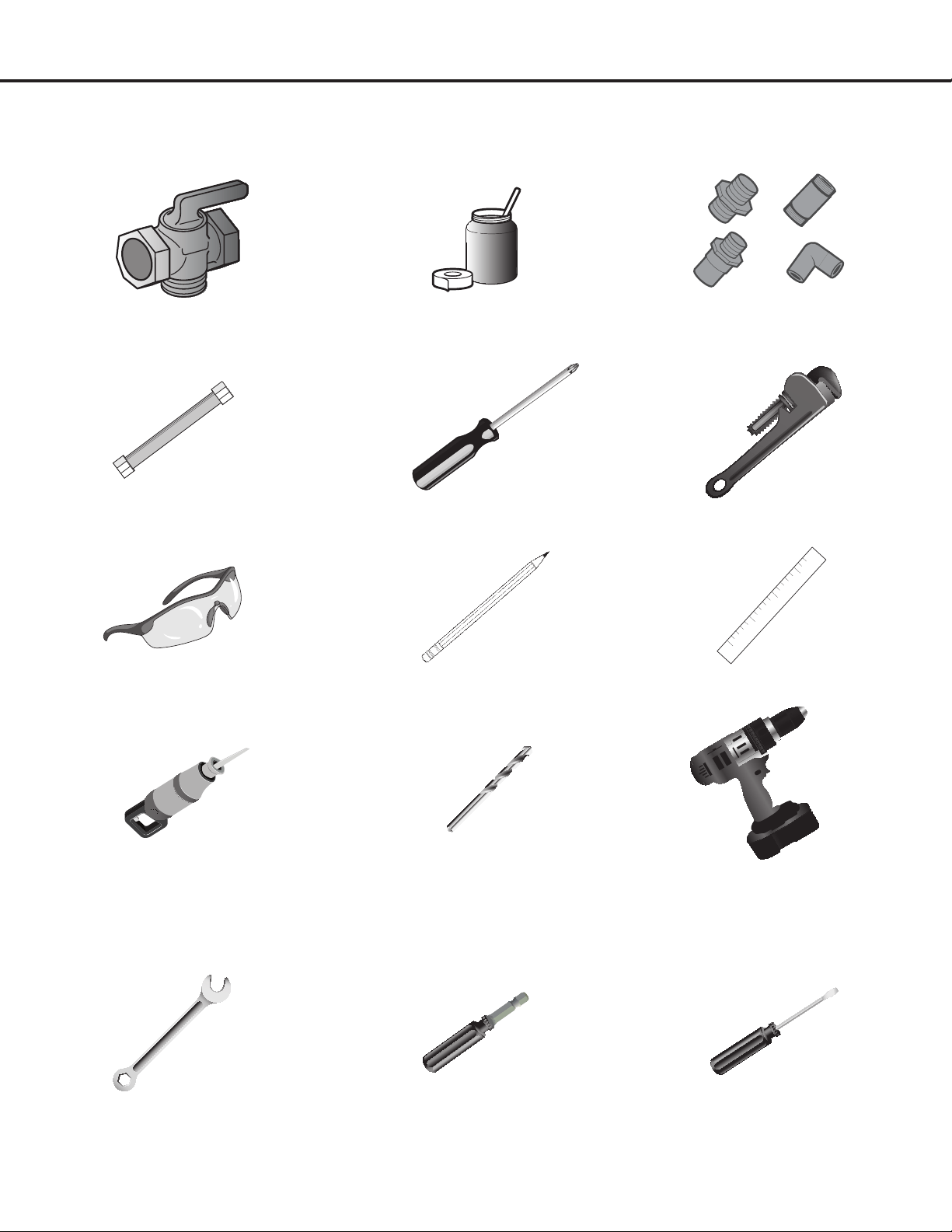
Wrench 7 mm Nut Driver Small Flat-head Screwdriver (2 to 2.4
mm or 3/32” tip size, 60 mm long)
Tools and Additional Parts Needed
Shut-OffValvePipe-joint compound resistant to LP
gas
Pipe Fittings
CSA-Approved Flexible ½” or ¾” Gas
Line
Phillips screwdriver Pipe wrench
Safety Glasses Pencil Ruler
Saber Saw 1/8” (3.2 mm) drill bit Electric or Hand Drill
For Additional Parts: Check local codes, consult gas supplier and check existing gas/electrical supply. See “Electrical
Requirements” and “Gas Supply Requirements” sections.
Installation
Tools you will need for LP conversion:
— 10 —
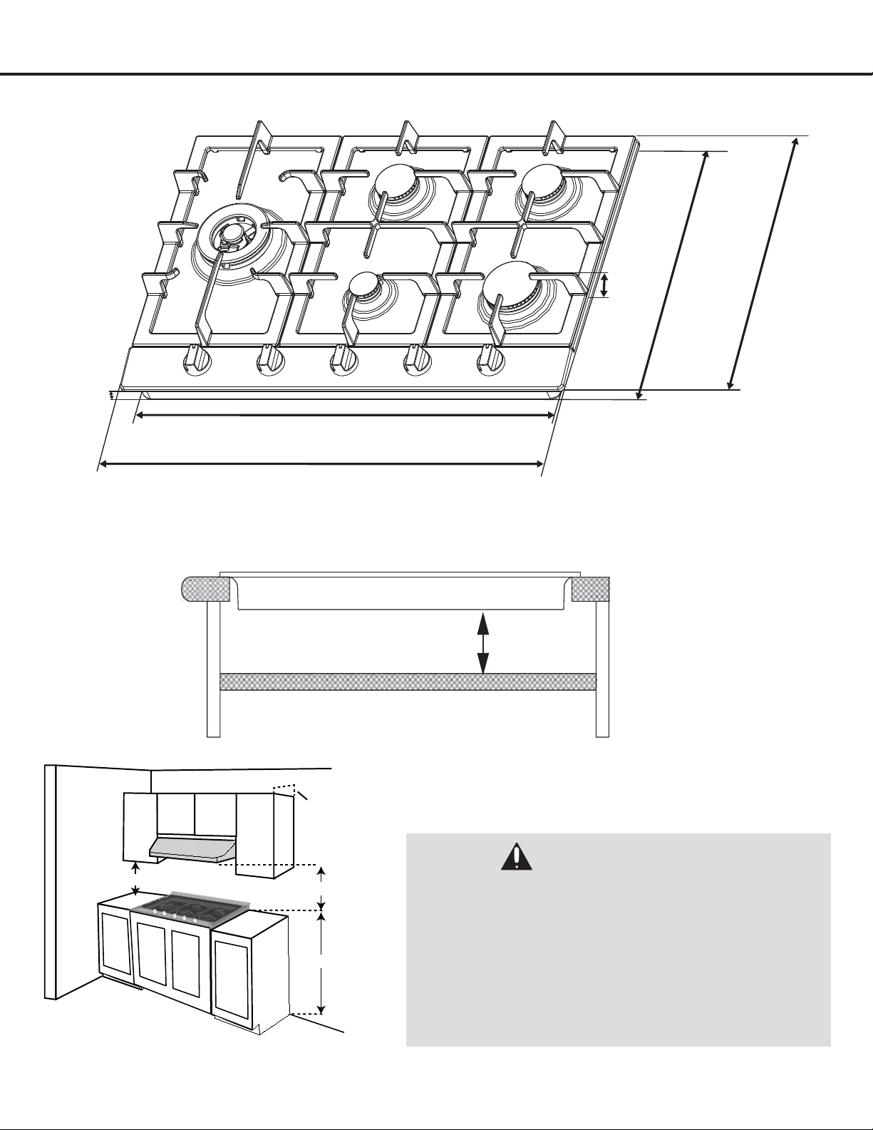
Installation
Dimensions
Figure 2
30” (76.2 cm) Min.
18” (45.7 cm) Min.
13” (33 cm) Max.
36” (91.4 cm)
30.3” (77 cm) or 33.8” (86 cm)
28.75” (73 cm)
20.1”
(51 cm)
19.3”
(49 cm)
2.5”
(6.4 cm)
1.5”
(3.7 cm)
DANGER:
•Ifrangehoodisinstalledabovecooktop,maintaina
30” minimum clearance between cooktop and bottom
of range hood. The range hood must be connected
directly to flues or to the outside.
•Maintain30”minimumclearancebetweencooktop
surface and cabinets installed above the cooktop.
•Arangehoodwithminimum350CFMthatprojectsat
least 5” beyond front of cabinets can reduce risk of
burns caused by reaching over heated surface units.
1.25” (3.2 cm) Canada
2.25” (5.7 cm) USA
Required clearance from bottom of cooktop to top of built-in oven or cabinet.
Bottom of cooktop
Top of built-in oven or cabinet
— 11 —
Installation
Installationandservicemustbeperformedbyaqualiedinstaller.Savetheseinstructionsforlocalelectricalinspector’suse.
Advance Preparation
•For proper operation of a gas appliance, the air necessary for the combustion of the gas must be able to ow into the
room naturally. The air must ow into the room directly through openings in the outside walls. These openings must
have an unobstructed cross-section not less than 2m
3
/h for each kw of power (see total power in kw on the appliance).
•This opening must be constructed so that it will not be obstructed from inside or outside, or constructed close to the
oor. The opening is recommended to be on the side opposite to that on which the ue gases are discharged.
•Avoid placing cabinetry directly above cooktop when possible. If cabinetry is used above cooking surface, use
cabinets no more than 13” deep (see Figure 2).
•Working areas adjacent to the cooktop should have 18” minimum clearance between countertop and cabinet bottom.
•Make sure the wall coverings, countertop and cabinets around the cooktop can withstand heat (up to 200º F)
generated by the cooktop.
•Maintain 30” minimum clearance between cooktop surface and cabinets installed above the cooktop.
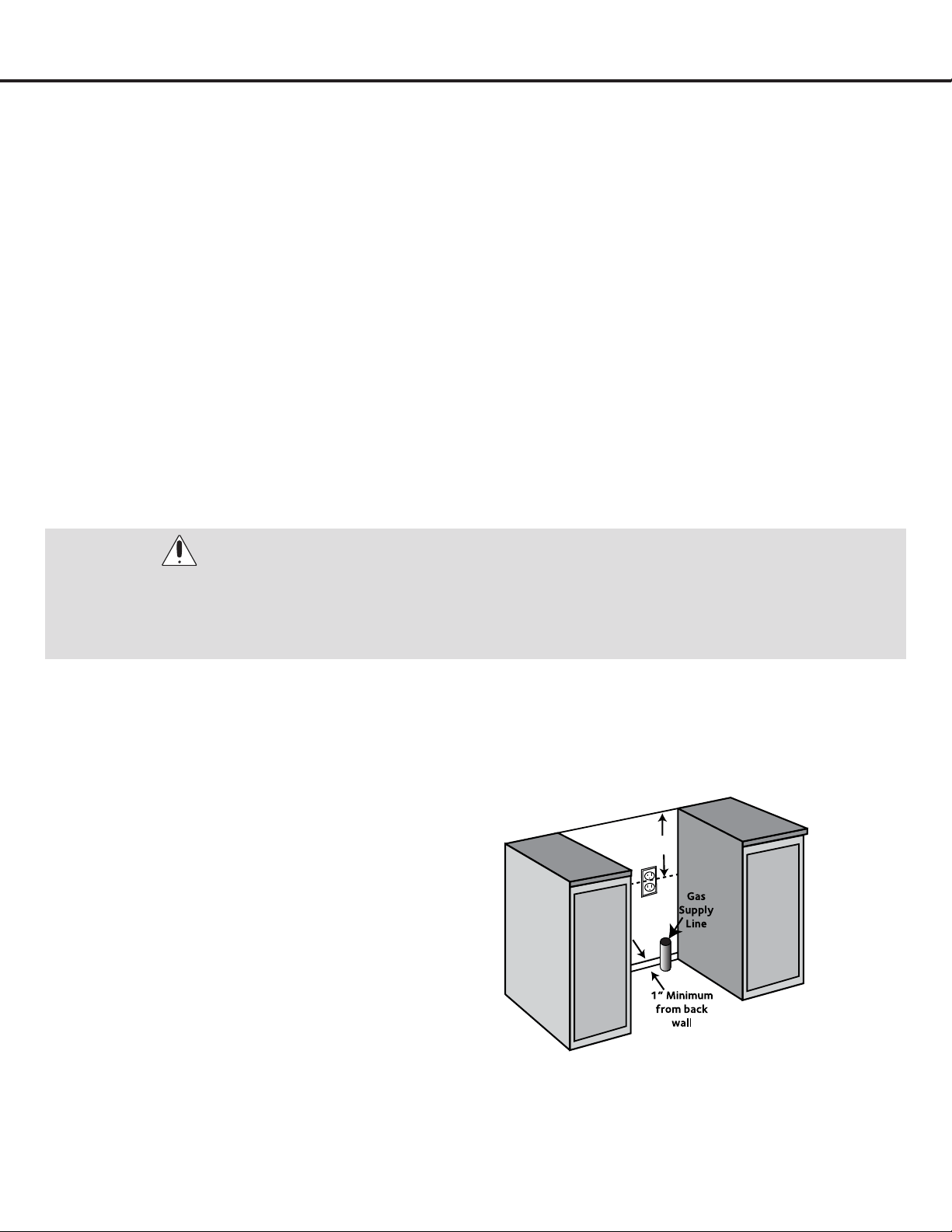
Provide an Adequate Gas and Electrical Supply
•Gas supply should be located near the opening for this cooktop and be a minimum of 1” from the back wall (see Figure
3). This cooktop is set for natural gas and is designed to operate at 5” water column pressure. The regulator is required
to provide a minimum of 6” water column to a maximum of 14” water column to the cooktop regulator.
•Theelectricsparkignitionfeatureforthismodelrequiresa120Velectricalpowersupplyandshouldbelocated12”
belowthecountertopandwithinreachofthecooktop’sfour-footpowercord.
WARNING:
Installation must comply with local codes. In the absence of local codes, the gas cooktop must comply with the
National Fuel Gas Code ANSI Z223.1—latest edition in the United States, or in Canada CAN/CGA B149.1, and CAN/
CGA B149.2, and the National Electrical Code ANSI/NFPA No. 70—latest edition in United States, or in Canada CSA
Standard C22.1, Canadian Electrical Code, Part 1, and local code requirements.
12”
Figure 3
— 12 —
STEP 1
Read the Safety Precautions
Please read the safety precautions on pages 4 to 6. Safety instructions pertaining to each step have been outlined in the
installation steps; however it is important to read ALL the safety instructions.
IMPORTANT: It is the installer’s responsibility to comply with installation clearances.
STEP 2
Plan Desired Location, Unpack the Appliance and Prepare Tools
Plan a desirable location that ts all requirements in the Safety and Install sections of this manual. Unpack the appliance
and parts carefully (all burners, burner caps and cooking grates). Make sure all parts are included as shown on page 8 and
set aside. Assemble all tools as shown on page 9. DO NOT remove the protective lm covering the appliance.
Installation
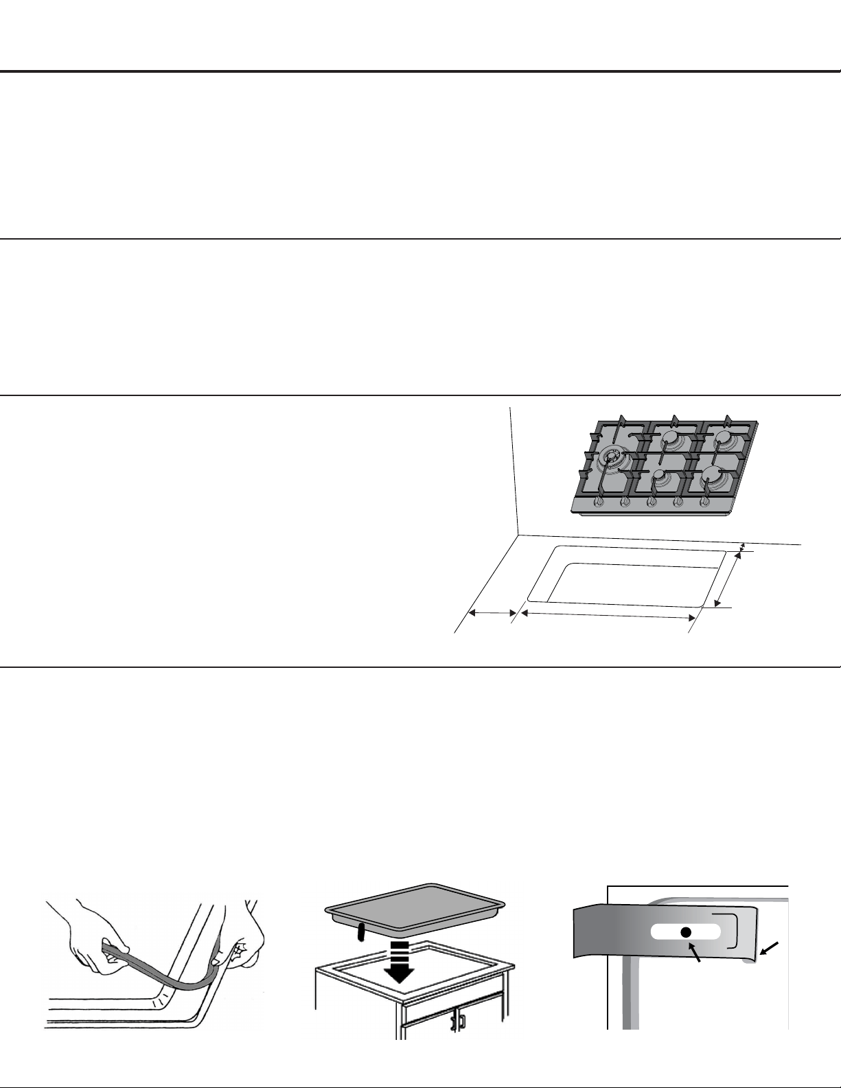
STEP 3
Cutting the Countertop
Figure 4
u
Use a 24” or deeper base cabinet.
v
Cut the opening in the countertop. To ensure
accuracy, it is best to make a template (see Figure 4)
for the opening.
Make sure the sides are parallel, and rear and front
cuts are exactly perpendicular to the sides. Observe
all minimum clearances.
28.75” (73 cm)
19.3”
(49 cm)
5.9”
(15 cm)
3”
(7.5 cm)
u
Before inserting the cooktop into the opening in
the countertop, remove the grates and burner
caps, turn the cooktop upside down and place
the special foam gasket around the bottom edge
of the cooktop (see Figure 5). It is important to x
this gasket evenly, without gaps or overlapping, to
prevent liquid seeping underneath the cooktop
.
v
After the foam gasket has been afxed, place the
cooktop into the countertop (see Figure 6).
w
Secure cooktop from underneath with the supplied
clips and screws (see Figure 7).
STEP 4
Installing Cooktop
Figure 5 Figure 6 Figure 7
Clip
Screw
Slot
Underside of cooktop
Underside of countertop
— 13 —
STEP 5
Installing the Pressure Regulator
This cooktop is set for natural gas and is designed to
operate at 5” water column pressure. The gas supply is
required to provide a minimum of 6” to a maximum of 14”
water column pressure to the cooktop regulator.
If the cooktop is converted for liquid petroleum (LP) gas, the
LP gas supply is required to provide a minimum of 10” to a
maximum of 14” water column to the cooktop regulator.
The pressure regulator must be connected in series with the
manifold of the cooktop and must remain in series with the
supply line regardless the type of gas being used.
Installation
WARNINGS:
•Neverreuseoldflexibleconnectors.Theuseof
old flexible connectors can cause gas leakage and
personal injury. Always use new flexible connectors
when installing a gas appliance. To reduce the
possibility of gas leakage, apply Teflon tape or a
thread compound approved for use with LP or Natural
gases to all threaded connections.
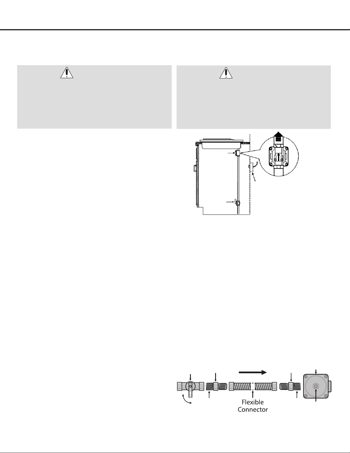
WARNINGS:
•Thegassupplylinemustbeequippedwithan
approved manual shut-off valve. In an easily
accessible location in the same room as the cooktop.
Do not block access to the shutoff valve. Be sure you
know how and where to shut off the gas supply to
the cooktop. Install the electrical outlet 12” below the
countertop (see Figure 8).
Figure 8
u
The gas inlet is located on the bottom of the cooktop
at the rear and 8 ½” from the right hand edge of the
cooktop. Make gas connection through rear wall, or
on cabinet oor at rear. Install the house gas supply at
least 1” from the back wall.
v
When installing, t a safety tap at the end of the
pipeline. The appliance leaves the factory tested and
set for natural gas. Make sure that the type of gas
to be supplied to the appliance is the same as that
shown on the label afxed to the underside of the
cooktop.
w
Make the connection to the gas system using a
rigid ½” or ¾” metal pipe and regulation unions, or
with a stainless-steel hose complying with the local
standard. If metal hoses are used, take care that
they do not come into contact with mobile parts and
are not crushed. This must also be checked if the
cooktop is to be combined with an oven.
x
The gas intake connection of the appliance has
a “male thread.” When making the connection,
take care not to apply stresses of any kind to the
appliance. Over-tightening may crack the regulator
resulting in a gas leak and possible re or explosion
(see Figure 9).
y
Once regulator is in place, open the shutoff valve in
the gas supply line. Wait a few minutes for gas to
move through the gas line.
U
After connecting the cooktop to the gas supply,
make sure all burners knobs are in the OFF position
and check the system for leaks with a manometer. If
a manometer is not available, turn on the gas supply
and use a liquid leak detector (or soap and water) at
all joints and connections to check for leaks.
Joint Joint
Off
On
Manual
Shut off
Valve
Pressure
Regulator
Flare
Union
Flare
Union
Gas Flow
Access
Cap
Figure 9
Rear view
of regulator
(note direction
of arrow)
To cooktop
Pressure
regulator
Shut-off
valve
Electrical outlet 12”
below countertop
— 14 —
Installation
WARNINGS:
•Donotuseaflametocheckforleaksfromgasconnections.Checkingforleakswithaflamemayresultinafireor
explosion.
•Tightenallconnectionsifnecessarytopreventgasleakageinthecooktoporsupplyline.
•Checkalignmentofcontrolknobvalvesafterconnectingthecooktoptothegassupplytobesurethecooktop
manifold pipe has not moved. A misalignment could cause the valve stems to rub on the control panel, resulting in a
gas leak at the valve.
•Disconnectthiscooktopanditsindividualmanualshutoffvalvefromthegassupplypipingsystemduringany
pressure testing of that system at test pressures greater than 1/2 psig (3.5 kPa or 14” water column).
•Isolatethecooktopfromthegassupplypipingsystembyclosingitsindividualmanualshutoffvalveduringany
pressure testing of the gas supply piping system at test pressures equal to or less than 1/2 psig (3.5 kPa or 14” water
column).
Before making the connection, make sure that:
STEP 6
Electrical Connection
u
The safety circuit-breaker and the electrical system
are able to with stand the load of the appliance
.
v
The power supply system has a ground connection
in good working order in accordance with the
regulations in force.
w
The electrical socket is easily accessible with the
appliance installed. In all cases, the power supply
lead must be positioned so that it does not reach a
temperature 50°C above the room temperature at
any point.
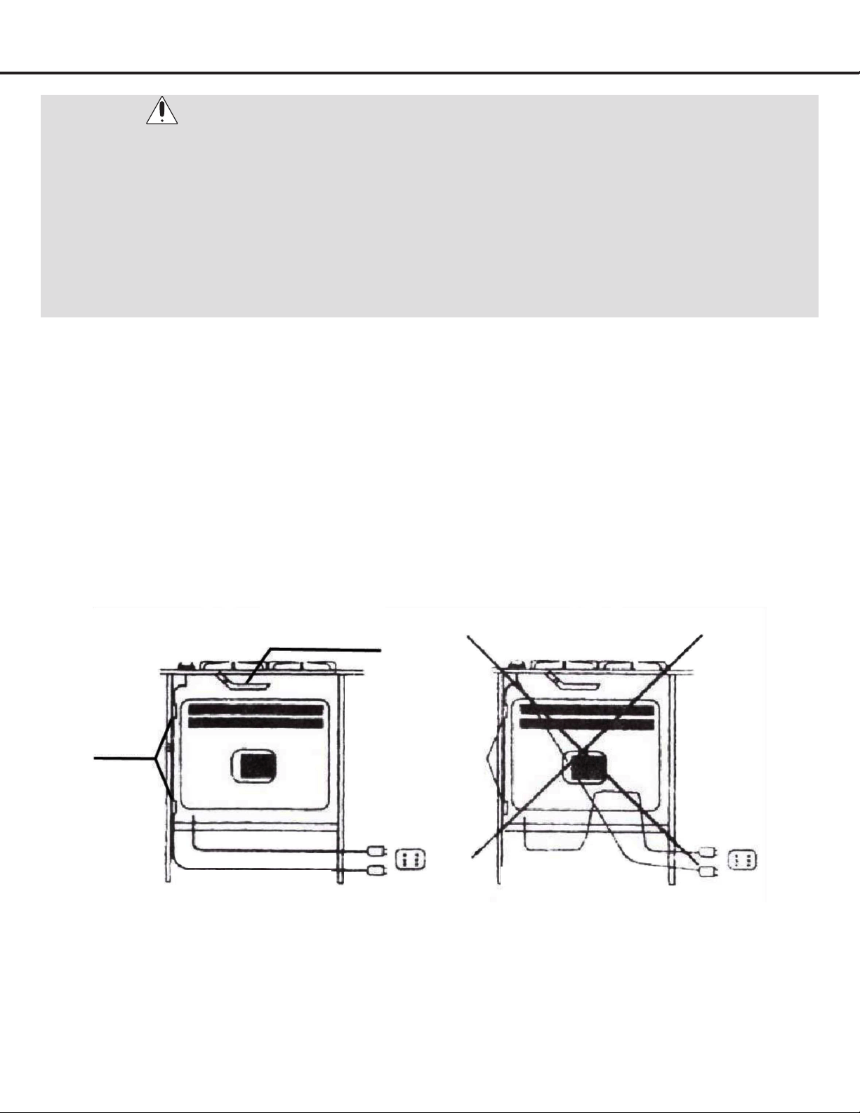
x
If installed above a built-in oven, the cooktop cable
must not touch the oven below (see Figure 10).
Figure 10
Copper pipe or
stainless steel hose
Clamps
YES
NO
Rear view Rear view
— 15 —
Installation
The electrode of the electronic ignition system is positioned above the surface of the burner base. Do not remove a burner
cap or touch the electrode of a burner while another is turned on. Damage or electrical shock may occur.
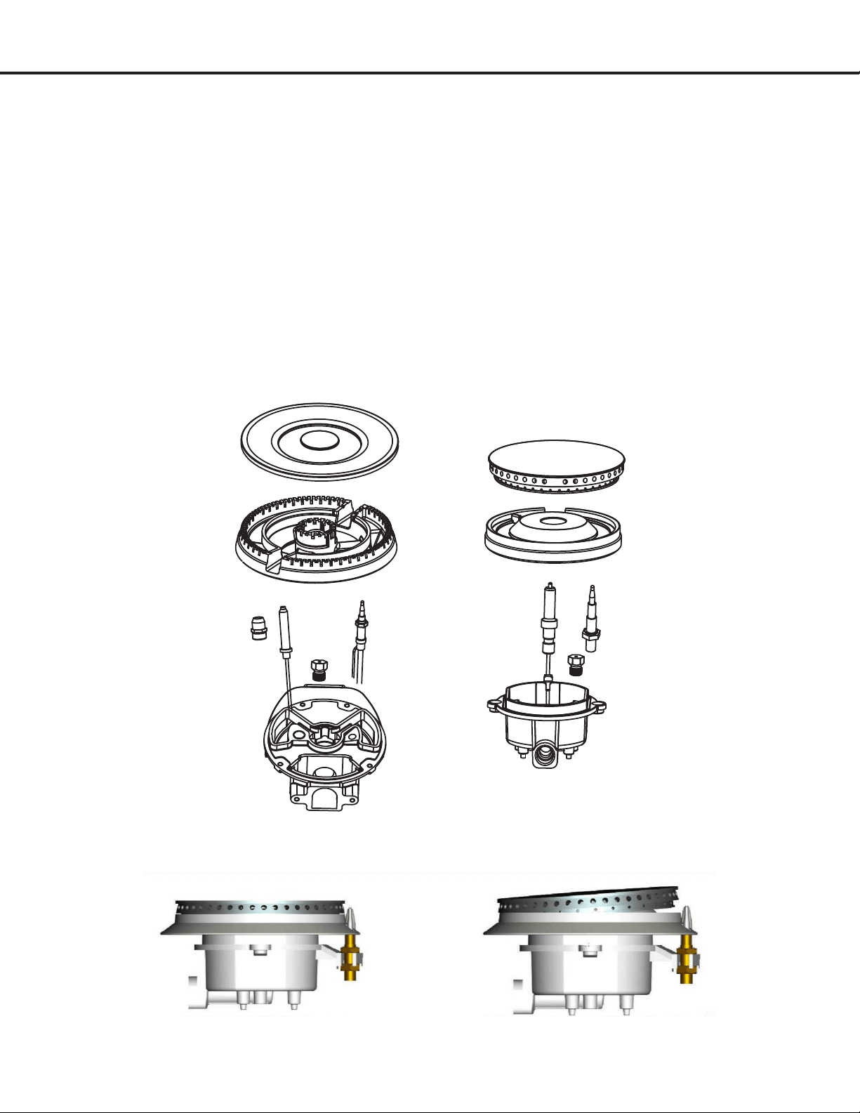
STEP 7
Assembling the Burners
u
Place burner heads over the burner base. Make sure
the hole in the burner head is properly aligned with
the electrode in the burner base (see Figure 11).
v
Place the burner caps on the burner heads. Make
sure that the burner caps are properly seated on the
burner head (see Figure 12).
w
Operation of the electric igniters should be tested
after the cooktop and supply line have been
carefully checked for leaks and the cooktop has
been connected to the electrical power. To check
igniters, push and turn a burner valve to the LITE
position. All spark igniters will make a series of
sparks (ticking sounds), but only the burner turned
to LITE will light.
Figure 11
Figure 12
PROPERLY SEATED NOT PROPERLY SEATED
— 16 —
Installation
STEP 8 (Optional)
(Must be done before Step 6 if converting to Propane)
Liqueed Petroleum (Propane)
Gas Conversion
This appliance can be used with Natural Gas or LP/Propane Gas. It is shipped from the factory for use with Natural Gas. A kit for
converting to LP gas is supplied with your appliance.
Thekitismarked“FORLP/PROPANEGASCONVERSION”.
When the cooktop is converted for liquid petroleum (LP) gas, the LP gas supply is required to provide a minimum of 10” to a
maximum of 14” water column to the cooktop regulator.
WARNINGS:
•PleasemakesuretoreadALLsafetyprecautionsonpages4to6.
•FailuretomaketheappropriateconversionafterStep4canresultinseriouspersonalinjuryandpropertydamage.
•
The conversion must be performed by a qualified service technician in accordance with the kit instructions and all local
codes and requirements. Failure to follow instructions could result in serious injury or property damage. The qualified
agency performing this work assumes responsibility for the conversion.
BURNER TYPE
MAX
OUTPUT
MIN
OUTPUT
Natural Gas LPG
BTU BTU Nozzle mm Cons m
3
/h Nozzle mm Cons g/h
Auxiliary 5000 1500 1 × 1.10 0.14 1 × 0.70 105
Semi-Rapid 6800 2200 1 × 1.29 0.19 1 × 0.80 142
Rapid 8500 2850 1 × 1.45 0.29 1 × 0.91 182
Triple Ring 18000 2500 1 × 2.1 0.5 1 × 1.26 377
Figure 13
56
80
70
80
91
126
Figure 14
— 17 —
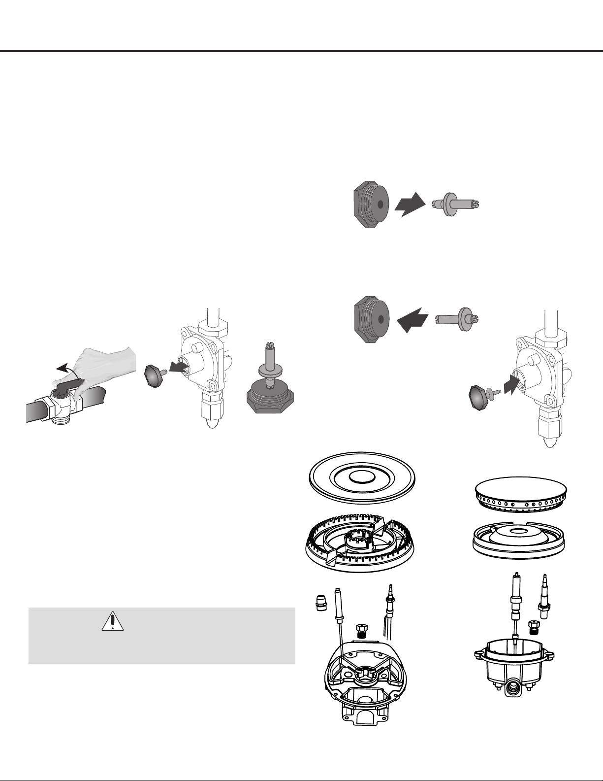
a) Disconnect all electrical power, at the main circuit breaker or
fuse box.
b) Shut off the gas supply to the cooktop by closing the
manual shut-off valve (see Figure 15).
c) Adjust the pressure regulator by doing the following:
u
Unscrew the regulator cap with the wrench (see Figure
16).
v
This is how the retainer pin looks for Natural Gas
usage (see Figure 17).
w
Remove the retainer pin (see Figure 18).
x
Reverse the retainer pin and put back into the
regulator cap (see Figure 19). This is how the
regulator pin looks for LP gas usage.
y
Screw the regulator cap
back into the regulator and
re-attach the regulator to
the nipple and are union
(see Figures 9 and 20).
Installation
STEP 8 (Continued)
Liqueed Petroleum (Propane)
Gas Conversion
Adjusting the Regulator Pressure
Figure 16 Figure 17
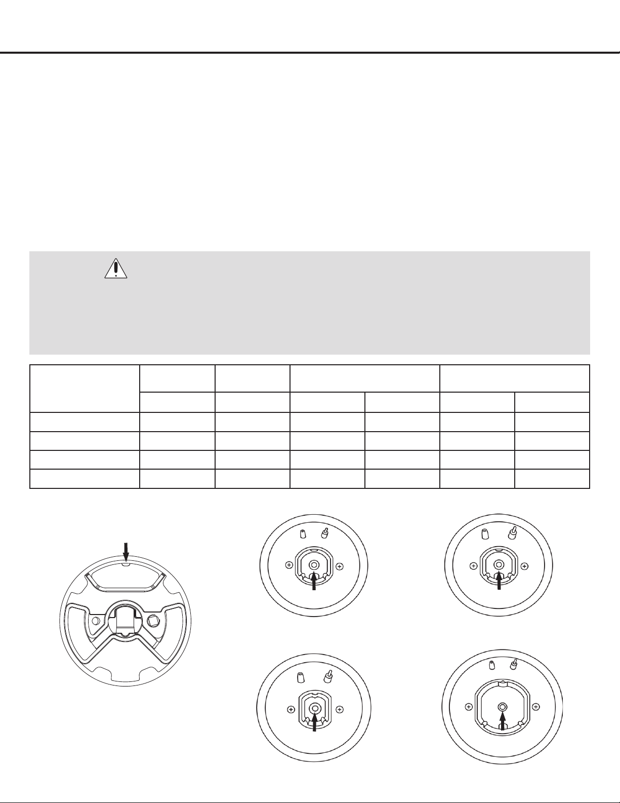
Changing Burner Nozzles
INSTALLATION TIP: First remove all nozzles and then
start replacing them. This will help to prevent the
possibility that some may not be replaced.
U
Remove the burner grates, burner caps and burner
heads.
V
Using a 7 mm nut driver, remove the burner nozzles.
W
Install the proper nozzles in the exact locations as
noted on Figure 21.
X
Replace the burner bases, heads, caps and top
grates. Make sure burner caps are properly seated
on the burner head (see Figure 12).
Figure 18
Figure 19
Figure 20
Figure 21
TRIPLE RING BURNER
5 NOZZLES
AUXILARY BURNER
SEMI-RAPID BURNER
RAPID BURNER
1 NOZZLE EACH
WARNINGS:
Carefully read and observe each nozzle label for correct
location (see Figure 13).
Figure 15
— 18 —
Installation
STEP 8 (Continued)
Liqueed Petroleum (Propane)
Gas Conversion
Adjust Burner Flames
u
Turn all burners on highest setting and check the
ames. They should be blue in color and may have
some yellow tipping at the ends of the ame when
using LP gas. Foreign particles in the gas line may
cause an orange ame at rst, but this will soon
disappear.
v
Turn the cooktop burner knob to “LO” while
observing the ame.
w
Adjustments must be made with two other burners
in operation on a medium setting. This prevents the
upper row of ames from being set too low, resulting
in the ame being extinguished when other burners
are turned on.
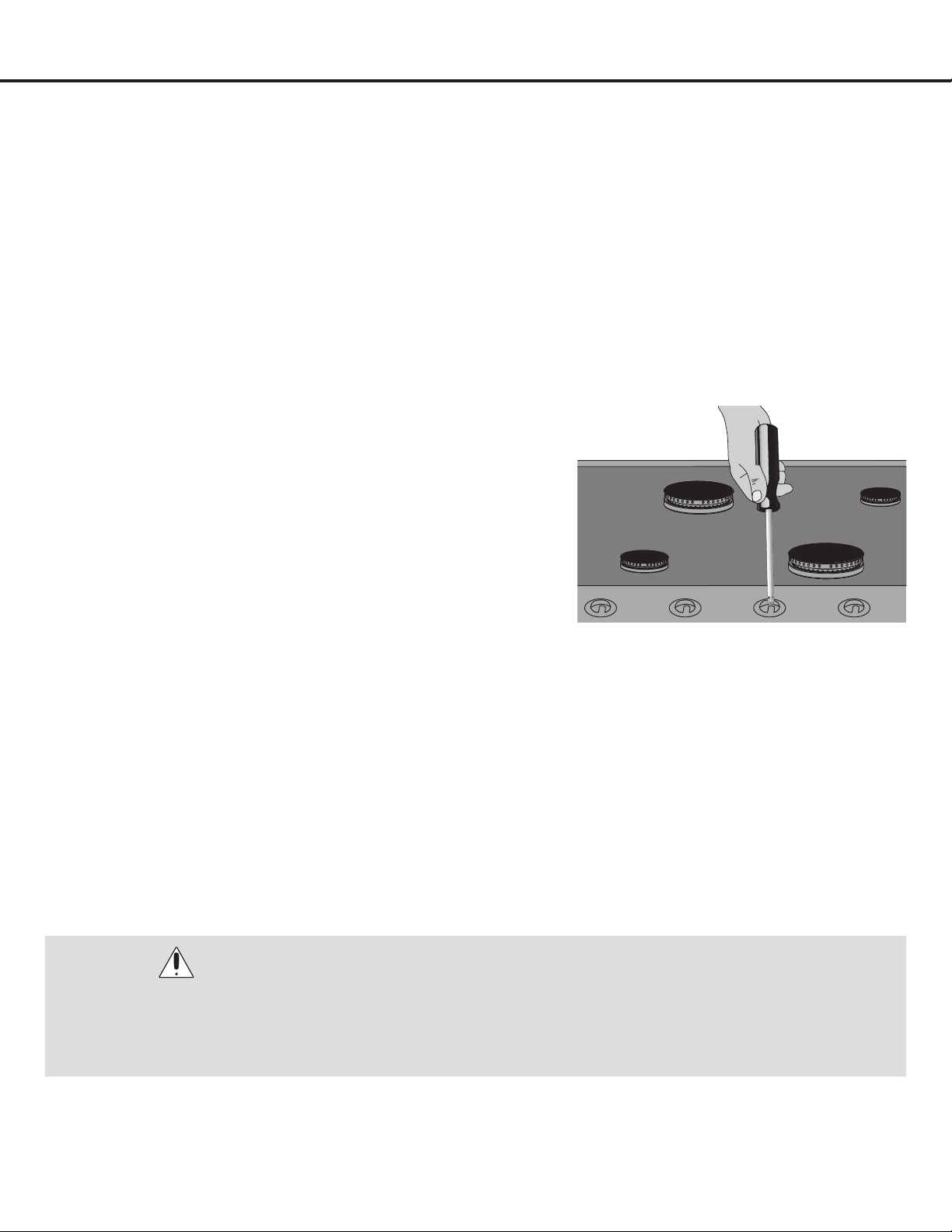
•To adjust the ame, remove the knobs, insert a screwdriver
through the access hole in valve shaft as shown (see Figure
22). Make the adjustment by slowly turning the screw until
ame appearance is correct.
•If the ames are too small or uttered, open the valve more
than the original setting.
•If the ames are too large, close the valve more than the
original setting.
Testing Flame Stability
Test 1——Turn the knob from “HI” to “LO” quickly. If the upper row of ames goes out at this setting, increase the ame size and
test again.
Test 2——With the burner on “LO”, open and close the cabinet door under the cooktop. If the ame is extinguished by the air
currents created by the door movement, increase the ame height and test again.
Flame Re-Check
After the adjustment is made, turn all burners off. Ignite each burner individually. Observe the ame at the “HI” position. Rotate
the knob to the lowest setting and be sure that the ame size decreases as the knob is rotated counter-clockwise.
WARNINGS:
Once the conversion has been completed and has passed testing, fill out the conversion sticker and include your name,
organization and the date conversion is made. Apply the sticker near the cooktop gas inlet opening to alert others in the
future that this appliance has been converted. If converting back to Natural Gas, please remove the sticker so others know
that the appliance is set to use its original gas.
Figure 22
— 19 —
u
Front panel
v
Knob for Triple-ring burner
w
Knob for Semi-rapid burner
x
Knob for Auxiliary burner
y
Knob for Semi-rapid burner
U
Knob for Rapid burner
V
Auxiliary burner - 5,000 BTU
W
Rapid burner – 8,500 BTU
X
Semi-rapid burners – 6,800 BTU
at
Triple-ring burner – 18,000 BTU
Operation
•Formostcooking,startonthehighestcontrolsetting
and then turn to a lower one to complete the process.
The size and type of utensil used and the amount of
food being cooked will inuence the setting needed for
cooking.
•Fordeepfatfrying,useathermometerandadjustthe
surface control knob accordingly. If the fat is too cool,
the food will absorb the fat and be greasy. If the fat is too
hot, the food will brown so quickly that the center will be
undercooked. Do not attempt to deep fry too much food
at once as the food will neither brown nor cook properly.
Surface Cooking
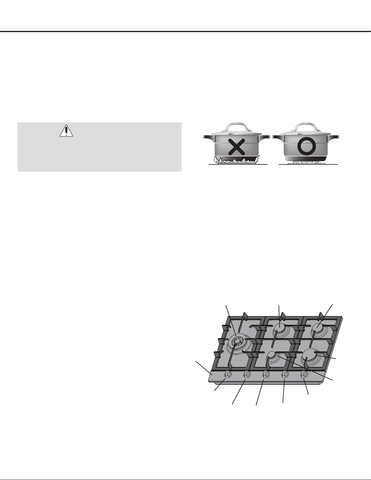
Flame Size
WARNING:
Never extend the flame beyond the outer edge of the
utensil (see Figure 23). A higher flame simply wastes
heat and energy, and increases your risk of being
burned by the flame.
Proper Burner Adjustments
•The color of the ame is the key to proper burner adjustment. A good ame is clear, blue and hardly visible in a well-
lighted room. Each cone of ame should be steady and sharply dened. Adjust or clean burner if ame is yellow-orange.
To clean burners, see instructions under Care and Cleaning.
Location of the Burners
3”
u
v
w
y
U
V
W
XXat
x
Figure 23
Figure 24
— 20 —
Operation
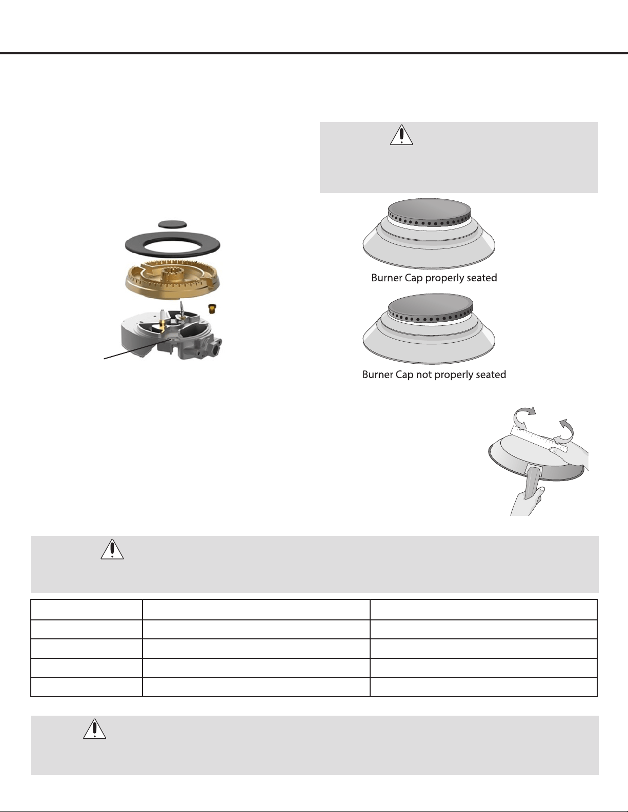
Placement of Burner Heads and Caps
For all burners:
•Place a burner cap on each burner head (see Figure
25), matching the cap size to the head size. The cap for
each burner has an inner locating ring which centers
the cap correctly on the burner head. Be sure that all
the burner caps and burner heads are correctly placed
BEFORE using your appliance.
•Make sure each burner cap is properly aligned and level
(see Figure 26).
Surface Cooking Utensils
•For lower gas consumption and better efciency: Use only at-bottomed pans of
dimensions suitable for the burners, as shown in the table below. Check for atness
by rotating a ruler across the bottom of the pan. There should be no gaps between
the pan and ruler. As soon as a liquid comes to a boil take care to turn the ame down to a
level that will just keep it simmering.
•Specialty pans (lobster pots and pressure cookers) may be used but must conform to the
recommended cookware requirements.
WARNING:
Turn the burner on to determine if it will light. If the
burner does not light, contact a qualified service
center. Do not service the sealed burner yourself.
WARNING:
During cooking processes involving fats or oils, watch your foods carefully because these substances may catch fire if
brought to high temperatures.
Burner Minimum Diameter of Pan Maximum Diameter of Pan
Auxiliary 10 cm (4 inches) 16 cm (6 ¼ inches)
Semi-Rapid 12 cm (4 ¾ inches) 20 cm (8 inches)
Rapid 18 cm (7 inches) 22 cm (8¾ inches)
Triple Ring 22 cm (8 ¾ inches) 26 cm (10 ¼ inches)
NOTE:
Alwaysuseautensilforitsintendedpurpose.Followmanufacturer’sinstructions.Someutensilswerenotmadetobe
used in the oven or on the cooktop.
Figure 25 Figure 26
Figure 27
Figure 28
Electrode
Burner base
Burner head
assembly
Burner cap
— 21 —
Operation
To Operate the Surface Burners
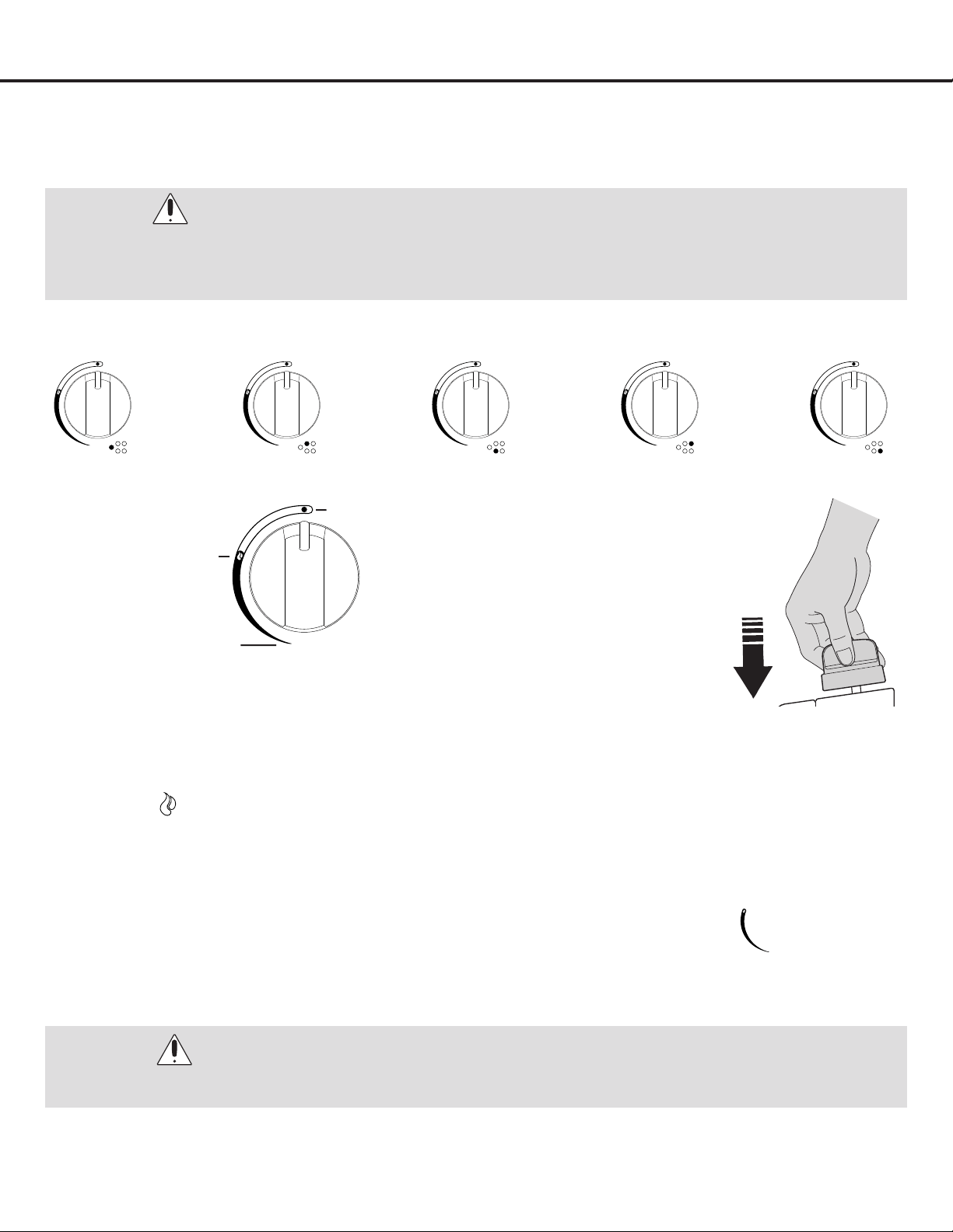
Knob Symbols
Lighting the Burners
u
To obtain a ame more easily, light the burner before placing a cooking utensil on the
burner grate.
v
To light a burner, press the knob of the burner fully down and turn it anti-clockwise to the “maximum ow” setting
symbol:
w
After lighting the ame, keep the knob pressed down for about 10 seconds. This is necessary to heat up the
thermocouple and activate the safety valve, which would otherwise cut off the gas ow.
x
Then check that the ame is even and turn the control knob to adjust the ame as required:
y
In the instance of a power outage, place a lit match near the burner and proceed as already described. If the burner
does not light after a few attempts, check that the “burner cap” and “ame cap” are correctly positioned.
U
Toturnofftheame,turnthecontrolknobclockwisetothe:•symbol.Beforeremovingpansfromtheburners,
always lower or turn off the ame.
WARNING:
Do not place plastic items such as salt and pepper shakers, spoon holders or plastic wrappings on top of the cooktop
when it is in use. These items could melt or ignite. Potholders, towels or wood spoons could catch fire if placed too
close to a flame.
Setting Surface Controls
Regardless of size, always select a utensil that is suitable for the amount and type of food being prepared. Select a burner
and ame size appropriate to the pan. Never allow ames to extend beyond the outer edge of the pan.
WARNING:
ALWAYS USE CAUTION WHEN LIGHTING BURNERS MANUALLY.
Figure 29
Figure 30
Figure 31
Off - No gas ow
On – Maximum gas ow
Minimum gas ow
— 22 —
Care and Cleaning
Control Knobs
•For general cleaning, use hot, soapy water and a cloth.
For more difcult soils and built-up grease, apply a liquid
detergent directly onto the soil. Rinse with a damp cloth
and dry.
•DO NOT use steel wool or acidic cleaners on the knobs;
as they can scratch.
Burner Grates
•Clean burner grates in the dishwasher and dry upon
removal.
Burner Caps
•Should you ever need to remove the burner caps for
cleaning lift the burner cap off the burner head. Clean
heavy soils with an absorbent cloth. Rinse with a clean,
damp cloth and immediately thoroughly dry including
the bottom and inside of the cap.
•Do not use harsh abrasive cleaners. They can scratch
the cap. Do not clean burner caps in dishwasher.
Burner Heads
•The holes in the burners of your cooktop MUST be kept
clean at all times for proper ignition and a complete,
even ame. Remove any food from between the burner
slots using a small nonabrasive brush like a toothbrush
and afterwards wipe using a damp cloth. To remove
deposits from the burner cavities, remove the cap and
separate the two parts. Clean the burner holes routinely
with a small gauge wire or needle and especially after
bad spillovers which could clog these holes. After
cleaning, put the two parts back together and return
them correctly to their position, making sure they are
seated and level.
•DO NOT put burner units in the dishwasher.
Stainless Steel
•Clean stainless steel with hot, soapy water and a
dishcloth. Rinse with clean water and a cloth. Do not
use cleaners with high concentrations of chlorides
or chlorines. Do not use harsh scrubbing cleaners.
Only use kitchen cleaners that are especially made for
cleaning stainless steel.
WARNINGS:
•PleasemakesuretoreadALLsafetyprecautions
on pages 4 to 6.
•Electric Shock Hazard.
•Toavoidpossibleburnsusecarewhencleaning
the appliance.
- DO NOT attempt to clean the cooktop
whenever the cooktop or burner heads are still
hot.
- To avoid possible burns DO NOT attempt any of
the following cleaning instructions before turning
OFF ALL of the surface burners and allowing
them to cool.
IMPORTANT: Always follow label instructions on
cleaning products.
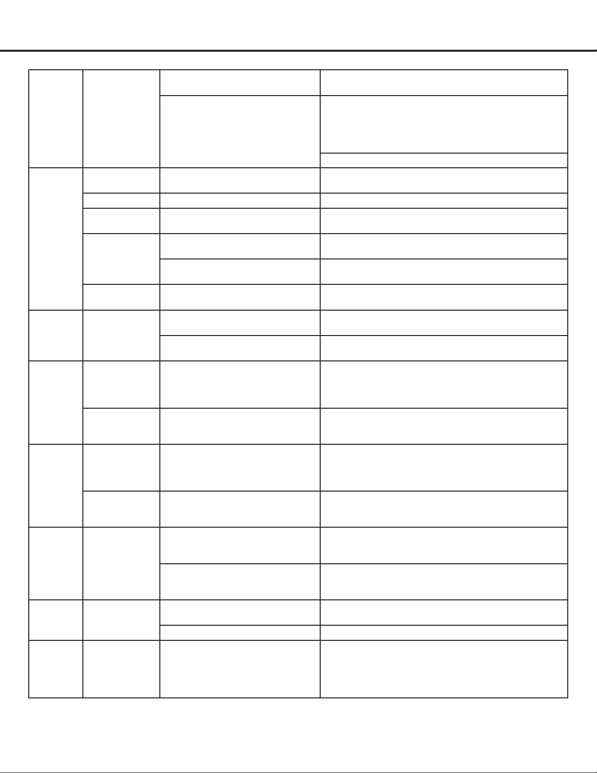
Troubleshooting Tips
Problem Possible Cause Solution
No spark
occurs
when
lighting
burner.
Burner cap.
The burner is not installed
correctly.
Install the burner pieces again.
Igniter.
Check all connections to the
ignition module.
Igniter is not positioned correctly. Adjust the distance by 3 - 4 mm.
Igniter is broken. Replace with supplied igniter. Note: There are two
igniter sizes:
- large for the triple ring burner.
- small for all other burners.
Electricity.
Ensure electric current to small
black box on gas valve is running.
Reset the electrical breaker if necessary.
The electrical wires or the plug are
not connected well.
Connect with electrical power again.
IMPORTANT:
Before calling for service, review this list. It may save you both time and expense. This list includes common experiences
that are not the result of defective workmanship or material in your cooktop.
— 23 —
Troubleshooting Tips
The ame
goes out
once the
knob is
released.
Thermocouple.
Burner knob not pressed down
long enough.
Press and turn the burner knob again and keep holding
for 5 to 10 seconds after the burner has been lit.
Attach thermocouple to a
functional gas valve to determine
if the issue is the thermocouple or
the gas valve.
If problem is the thermocouple, replace with supplied
thermocouple. Note: There are two thermocouple
sizes:
- large for the triple ring burner.
- small for all other burners.
If problem is the gas valve, contact the vendor.
Burner
won’t
ignite or
burns
unevenly.
Gas valve.
The gas valve is not open or
completely open.
Make sure the gas valve is completely open.
Gas pipe. There may be air in the gas pipe. Ignite repeatedly until ame catches.
Gas connecting
pipes.
The gas connecting pipes are
blocked.
Adjust or change the connecting pipes.
Burner cap.
The burner cap is not placed
correctly.
Install the burner pieces again.
Some holes in the burner cap lid
are blocked.
Clean the holes in the burner cap.
Igniter.
The igniter is wet or contaminated
by food residue.
Clean and dry the igniter.
The ame
goes out
during
operation.
Thermocouple.
The thermocouple is contaminated
by food residue.
Clean the thermocouple.
The ame is too low and cannot
reach the thermocouple.
Adjust the ame a little higher.
Flame is
too high.
Nozzle.
The burner is connected with a
natural gas nozzle and needs to be
connected with a propane nozzle.
Change the natural gas nozzle to a liquid propane
nozzle. (Use the supplied screwdriver when changing
the nozzles. Never use an electric screwdriver or drill to
remove/replace the nozzles or to make the hole larger.)
Regulator.
The regulator is set for natural gas
use and needs to be switched to
liquid propane.
Contact your local qualied service technician to set
the regulator so that it is set for liquid propane.
Flame is
too low.
Nozzle.
The burner is connected with a
liquid propane nozzle and needs
to be connected with a natural gas
nozzle.
Change the liquid propane nozzle to a natural gas
nozzle. (Use the supplied screwdriver when changing
the nozzles. Never use an electric screwdriver or drill to
remove/replace the nozzles or to make the hole larger.)
Regulator.
The regulator is set for liquid
propane use and needs to be
switched to natural gas.
Contact your local qualied service technician to set
the regulator so that it is set for natural gas.
Gas not
reaching
the
cooktop.
Gas supply.
Ensure the service valve is
connected to the gas supply.
If the valve is not connected, contact your local
qualied service technician to connect the service
valve to the gas supply.
The arrow on the regulator is not
pointing towards the cooktop.
Contact your local qualied service technician to
reverse the regulator so that the arrow is pointing
towards the cooktop.
Strange
smell.
Gas leaking
The gas supply pipe is old and
broken.
Contact your local qualied service technician to
change the gas supply pipes.
The main burner is not lit. Ignite again after there is no strange smell.
Hissing
noise
coming
from
burner.
Burners.
Only possible cause is burner
pieces are not placed correctly on
the burner support.
Install the burner pieces again.
— 24 —
Please register your product warranty by visiting the Ancona Home website.
Canada & USA
Phone: 1-800-350-4562
Fax: 800-350-8563
Email: [email protected]
Website: www.anconahome.com
Ancona is in association with Mr Appliance for all after sales service calls.
Please contact their service provider or visit their website:
Phone: 1-888-998-2011
Website: www.mrappliance.com
© 2023 Copyright of Ancona Home. All rights reserved. This material may not be reproduced, displayed, modied or distributed.
MAAN2125-02