Installation/Operation
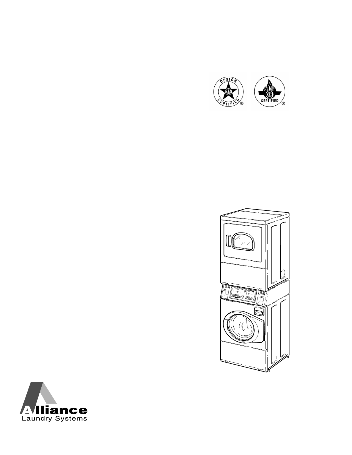
Stacked Washer/Dryers
Electric and Gas Models
SWD455C_SVG
Original Instructions
Keep These Instructions for Future Reference.
CAUTION: Read the instructions before using the machine.
(If this machine changes ownership, this manual must accompany machine.)
www.alliancelaundry.com
Part No. 805420ENR4
October 2017

WARNING
WARNING
Risk of fire. Highly flammable material.
W881
Read all instructions before using unit.
WARNING
FOR YOUR SAFETY, the information in this manual
must be followed to minimize the risk of fire or ex-
plosion or to prevent property damage, personal in-
jury or death.
W033
WARNING
• Do not store or use gasoline or other flammable
vapors and liquids in the vicinity of this or any
other appliance.
• WHAT TO DO IF YOU SMELL GAS:
• Do not try to light any appliance.
• Do not touch any electrical switch; do not use
any phone in your building.
• Clear the room, building or area of all occu-
pants.
• Immediately call your gas supplier from a
neighbor’s phone. Follow the gas supplier’s in-
structions.
• If you cannot reach your gas supplier, call the
fire department.
• Installation and service must be performed by a
qualified installer, service agency or the gas sup-
plier.
W052
IMPORTANT: Purchaser must consult the local gas
supplier for suggested instructions to be followed if
the dryer user smells gas. The gas utility instructions
plus the SAFETY and WARNING note directly above
must be posted in a prominent location near the dryer
for customer use.
WARNING
• Installation of unit must be performed by a quali-
fied installer.
• Install clothes dryer according to manufacturer’s
instructions and local codes.
• DO NOT install a clothes dryer with flexible plas-
tic venting materials. If flexible metal (foil type)
duct is installed, it must be of a specific type
identified by the appliance manufacturer as suita-
ble for use with clothes dryers. Refer to section
on connecting exhaust system. Flexible venting
materials are known to collapse, be easily crush-
ed, and trap lint. These conditions will obstruct
clothes dryer airflow and increase the risk of fire.
W729R1
WARNING
To reduce the risk of severe injury or death, follow all
installation instructions. Save these instructions.
W894
WARNING
FOR YOUR SAFETY
Do not store or use gasoline or other flammable va-
pors and liquids in the vicinity of this or any other
appliance.
W053
This product uses FreeRTOS V7.2.0 (www.freertos.org).
©
Copyright, Alliance Laundry Systems LLC -
DO NOT COPY or TRANSMIT
3 Part No. 805420ENR4

The following information applies to the state of Massachusetts,
USA.
• This appliance can only be installed by a Massachusetts li-
censed plumber or gas fitter.
• This appliance must be installed with a 36 inch [910 mm]
long flexible gas connector.
• A “T-Handle” type gas shut-off valve must be installed in the
gas supply line to this appliance.
• This appliance must not be installed in a bedroom or bath-
room.
©
Copyright, Alliance Laundry Systems LLC -
DO NOT COPY or TRANSMIT
4 Part No. 805420ENR4

Table of Contents
Safety Information..................................................................................7
Explanation of Safety Messages....................................................................... 7
Important Safety Instructions........................................................................... 7
Important Safety Instructions........................................................................... 8
Dimensions........................................................................................... 10
Installation........................................................................................... 14
Before You Start........................................................................................... 14
Tools........................................................................................................ 14
Order of Installation Steps..........................................................................14
Position Unit Near Installation Area............................................................... 14
Remove Shipping Materials........................................................................... 14
Connect Fill Hoses........................................................................................15
Water Supply Requirements....................................................................... 16
Connecting Hoses......................................................................................16
Risers.......................................................................................................16
Non-Gravity Drain Models - Connect Drain Hose to Drain Receptacle.............. 17
Standpipe Installation................................................................................ 17
Gravity Drain Models - Connect Drain Outlet to Drain System......................... 17
Gas Dryers - Connect Gas Supply Pipe........................................................... 18
Electric Dryer Only - Connect Electrical Plug..................................................20
Earth/Ground Information.......................................................................... 20
Connecting Power Cord with Three-Wire Plug.............................................22
Connecting Power Cord with Four-Wire Plug.............................................. 24
Connect Dryer Exhaust System...................................................................... 26
Exhaust Direction......................................................................................27
Exhaust System.........................................................................................27
Multi-Dryer Installation Exhaust Requirements............................................28
Position and Level the Unit............................................................................30
Wipe Out Inside of Washer and Dryer Drums.................................................. 31
Plug In the Washer and Dryer.........................................................................32
Electric Dryer........................................................................................... 32
Gas Dryer................................................................................................. 32
Washer..................................................................................................... 33
Check Installation......................................................................................... 35
Check Heat Source........................................................................................35
Electric Dryers.......................................................................................... 35
Gas Dryers................................................................................................35
Operation............................................................................................. 37
©
Copyright 2017, Alliance Laundry Systems LLC
All rights reserved. No part of the contents of this book may be reproduced or transmitted in any form or by any means without the expressed
written consent of the publisher.
©
Copyright, Alliance Laundry Systems LLC -
DO NOT COPY or TRANSMIT
5 Part No. 805420ENR4

Operation Instructions for Washers................................................................. 37
Load Laundry........................................................................................... 37
Close Loading Door...................................................................................37
Add Laundry Supplies............................................................................... 37
Determine Proper Controls.........................................................................38
Set Cycle.................................................................................................. 38
Set Wash Temperature............................................................................... 38
Set Soil Level............................................................................................38
Insert Coins or Card...................................................................................38
Start Washer..............................................................................................39
Indicator Lights.........................................................................................39
Operation Instructions for Dryers................................................................... 40
Clean Lint Filter........................................................................................40
Load Laundry........................................................................................... 40
Close Loading Door...................................................................................40
Determine Proper Controls.........................................................................40
Set Fabric Selector.....................................................................................40
Insert Coins or Card...................................................................................41
Start Dryer................................................................................................41
Indicator Lights.........................................................................................42
Maintenance......................................................................................... 43
User-Maintenance Instructions....................................................................... 43
Lubrication............................................................................................... 43
Cold Weather Care.................................................................................... 43
Extended Non-Use.................................................................................... 43
Care of Your Washer..................................................................................43
Care of Your Dryer.................................................................................... 43
Reinstallation of Shipping Materials............................................................... 44
Motor Overload Protector.............................................................................. 45
For Energy Conservation............................................................................... 45
Troubleshooting....................................................................................46
Contact Information............................................................................. 50
Installer Checklist.................................................................................51
©
Copyright, Alliance Laundry Systems LLC -
DO NOT COPY or TRANSMIT
6 Part No. 805420ENR4
Safety Information
Explanation of Safety Messages
Precautionary statements (“DANGER,” “WARNING,” and
“CAUTION”), followed by specific instructions, are found in this
manual and on machine decals. These precautions are intended
for the personal safety of the operator, user, servicer, and those
maintaining the machine.
DANGER
Indicates an imminently hazardous situation that, if
not avoided, will cause severe personal injury or
death.
WARNING
Indicates a hazardous situation that, if not avoided,
could cause severe personal injury or death.
CAUTION
Indicates a hazardous situation that, if not avoided,
may cause minor or moderate personal injury or
property damage.
Additional precautionary statements (“IMPORTANT” and
“NOTE”) are followed by specific instructions.
IMPORTANT: The word “IMPORTANT” is used to in-
form the reader of specific procedures where minor
machine damage will occur if the procedure is not fol-
lowed.
NOTE: The word “NOTE” is used to communicate in-
stallation, operation, maintenance or servicing informa-
tion that is important but not hazard related.
Important Safety Instructions
WASHER
Save These Instructions
WARNING
To reduce the risk of fire, electric shock, serious in-
jury or death to persons when using your washer,
follow these basic precautions:
W023
• Read all instructions before using the washer.
• Install the washer according to the INSTALLATION IN-
STRUCTIONS. Refer to the EARTH/GROUND INSTRUC-
TIONS in the INSTALLATION manual for the proper earth/
ground connection of the washer. All connections for water,
drain, electrical power and earth/ground must comply with lo-
cal codes and be made by licensed personnel when required.
Do not do it yourself.
• Do not install or store the washer where it will be exposed to
water and/or weather.
• Do not add the following substances or textiles containing
traces of the following substances to the wash water: gasoline,
kerosene, waxes, cooking oils, vegetable oils, machine oils,
dry-cleaning solvents, flammable chemicals, thinners or other
flammable or explosive substances. These substances give off
vapors that could ignite, explode or cause the fabric to catch
on fire by itself.
• Under certain conditions, hydrogen gas may be produced in a
hot water system that has not been used for two weeks or
more. HYDROGEN GAS IS EXPLOSIVE. If the hot water
system has not been used for such a period, before using a
washing machine or combination washer-dryer, turn on all hot
water faucets and let the water flow from each for several mi-
nutes. This will release any accumulated hydrogen gas. THE
GAS IS FLAMMABLE, DO NOT SMOKE OR USE AN
OPEN FLAME DURING THIS TIME.
• To reduce the risk of an electric shock or fire, DO NOT use an
extension cord or an adapter to connect the washer to the elec-
trical power source.
• Do not allow children to play on or in the washer. Close su-
pervision of children is necessary when the washer is used
near children. This appliance is not intended for use by per-
sons (including children) with reduced physical, sensory or
mental capabilities, or lack of experience and knowledge, un-
less they have been given supervision or instruction concern-
ing the use of the appliance by a person responsible for their
safety. This is a safety rule for all appliances.
• Cleaning and user maintenance shall not be made by children
without supervision.
Safety Information
©
Copyright, Alliance Laundry Systems LLC -
DO NOT COPY or TRANSMIT
7 Part No. 805420ENR4

• Children less than three years should be kept away unless
continuously supervised.
• Do not reach into the washer if the washtub or agitator, if ap-
plicable, is moving.
• Never operate the washer with any guards, panels and/or parts
removed or broken. DO NOT tamper with the controls or by-
pass any safety devices.
• Use your washer only for its intended purpose, washing
clothes. Always follow the fabric care instructions supplied
by the garment manufacturer.
• Always read and follow manufacturer’s instructions on pack-
ages of laundry and cleaning aids. To reduce the risk of poi-
soning or chemical burns, keep them out of the reach of chil-
dren at all times (preferably in a locked cabinet). Heed all
warnings or precautions.
• Do not use fabric softeners or products to eliminate static un-
less recommended by the manufacturer of the fabric softener
or product.
• Be sure water connections have a shut-off valve and that fill
hose connections are tight. CLOSE the shut-off valves at the
end of each wash day.
• Keep your washer in good condition. Bumping or dropping
the washer can damage safety features. If this occurs, have
your washer checked by a qualified service person.
• Do not repair or replace any part of the washer, or attempt any
servicing unless specifically recommended in the user-mainte-
nance instructions or in published user-repair instructions that
you understand and have the skills to carry out. ALWAYS dis-
connect the washer from electrical supply before attempting
any service.
• Disconnect the power cord by grasping the plug, not the cord.
If the supply cord is damaged, it must be replaced by the man-
ufacturer, its service agent or similarly qualified persons in or-
der to avoid a hazard.
• Before the washer is removed from service or discarded, re-
move the lid or door to the washing compartment.
• Failure to install, maintain, and/or operate this washer accord-
ing to the manufacturer’s instructions may result in conditions
which can produce bodily injury and/or property damage.
NOTE: The WARNING and IMPORTANT SAFETY IN-
STRUCTIONS appearing in this manual are not meant
to cover all possible conditions and situations that may
occur. Observe and be aware of other labels and pre-
cautions that are located on the machine. They are in-
tended to provide instruction for safe use of the ma-
chine. Common sense, caution and care must be exer-
cised when installing, maintaining, or operating the
washer.
Always contact your dealer, distributor, service agent or the man-
ufacturer about any problems or conditions you do not under-
stand.
Important Safety Instructions
DRYER
Save These Instructions
WARNING
To reduce the risk of fire, electric shock, serious in-
jury or death to persons when using your dryer, fol-
low these basic precautions:
W130
• Read all instructions before using the dryer.
• Install this dryer according to the INSTALLATION IN-
STRUCTIONS. Refer to the EARTH/GROUND INSTRUC-
TIONS in the INSTALLATION manual for the proper earth/
ground connection of the dryer. All connections for electrical
power, earth/ground and gas supply must comply with local
codes and be made by licensed personnel when required. Do
not do it yourself.
• Do not install or store the dryer where it will be exposed to
water and/or weather.
• Do not dry articles that have been previously cleaned in,
washed in, soaked in, or spotted with gasoline or machine
oils, vegetable or cooking oils, cleaning waxes or chemicals,
dry-cleaning solvents, thinner, anything containing chemicals
such as in mops and cleaning cloths, or other flammable or
explosive substances as they give off vapors that could ignite,
explode or cause fabric to catch on fire by itself.
• Items that have been soiled with substances such as cooking
oil, acetone, alcohol, petrol, kerosene, spot removers, turpen-
tine, waxes and wax removers, should be washed in hot water
with an extra amount of detergent before being dried in the
tumble dryer.
• To reduce the risk of fire, DO NOT DRY plastics or articles
containing foam or latex rubber or similarly textured rubber-
like materials, such as shower caps, water proof textiles, rub-
ber-backed articles, and clothes or pillows filled with foam
rubber pads.
• Do not tumble fiberglass curtains and draperies unless the la-
bel says it can be done. If they are dried, wipe out the cylinder
with a damp cloth to remove particles of fiberglass.
• Do not allow children to play on or in the dryer. Close super-
vision of children is necessary when the dryer is used near
children. This appliance is not intended for use by persons
(including children) with reduced physical, sensory or mental
capabilities, or lack of experience and knowledge, unless they
have been given supervision or instruction concerning the use
of the appliance by a person responsible for their safety. This
is a safety rule for all appliances.
• Cleaning and user maintenance shall not be made by children
without supervision.
• Children less than three years should be kept away unless
continuously supervised.
Safety Information
©
Copyright, Alliance Laundry Systems LLC -
DO NOT COPY or TRANSMIT
8 Part No. 805420ENR4

• Do not reach into the dryer if the cylinder is revolving.
• Use the dryer only for its intended purpose, drying clothes.
ALWAYS follow the fabric care instructions supplied by the
garment manufacturer and only use the dryer drum to dry tex-
tiles that have been washed in water.
• Always read and follow manufacturer’s instructions on pack-
ages of laundry and cleaning aids. Heed all warnings or pre-
cautions. To reduce the risk of poisoning or chemical burns,
keep them out of reach of children at all times (preferably in a
locked cabinet).
• Remove laundry immediately after the dryer stops.
• DO NOT operate the dryer if it is smoking, grinding or has
missing or broken parts or removed guards and/or panels. DO
NOT tamper with the controls or bypass any safety devices.
• DO NOT operate individual units if they have been separated
from a stack unit.
• Dryer will not operate with the loading door open. DO NOT
bypass the door safety switch by permitting the dryer to oper-
ate with the door open. The dryer will stop tumbling when the
door is opened. Do not use the dryer if it does not stop tum-
bling when the door is opened or starts tumbling without
pressing the START mechanism. Remove the dryer from use
and call the service person.
• ALWAYS clean the lint filter after every load. A layer of lint
in the filter reduces drying efficiency and prolongs drying
time. Keep area around the exhaust opening and adjacent sur-
rounding area free from the accumulation of lint, dust and
dirt. The interior of the dryer and the exhaust duct should be
cleaned periodically by qualified service personnel.
• Do not repair or replace any part of the dryer, or attempt any
servicing unless specifically recommended in the user-mainte-
nance instructions or in published user-repair instructions that
you understand and have the skills to carry out. ALWAYS dis-
connect the electrical power to the dryer before attempting
service. Disconnect the power cord by grasping the plug, not
the cord.
• Electric Models: If supply cord is damaged, it must be re-
placed by a special cord or assembly available from the man-
ufacturer or its service agent.
• Gas Models: If supply cord is damaged, it must be replaced
by the manufacturer, its service agent or similarly qualified
persons in order to avoid a hazard.
• Before the dryer is removed from service or discarded, re-
move the door to the drying compartment.
• Failure to install, maintain, and/or operate this machine ac-
cording to the manufacturer’s instructions may result in con-
ditions which can produce bodily injury and/or property dam-
age.
NOTE: The WARNING and IMPORTANT SAFETY IN-
STRUCTIONS appearing in this manual are not meant
to cover all possible conditions and situations that may
occur. Observe and be aware of other labels and pre-
cautions that are located on the machine. They are in-
tended to provide instruction for safe use of the ma-
chine. Common sense, caution and care must be exer-
cised when installing, maintaining, or operating the
dryer.
Always contact your dealer, distributor, service agent or the man-
ufacturer about any problems or conditions you do not under-
stand.
Safety Information
©
Copyright, Alliance Laundry Systems LLC -
DO NOT COPY or TRANSMIT
9 Part No. 805420ENR4
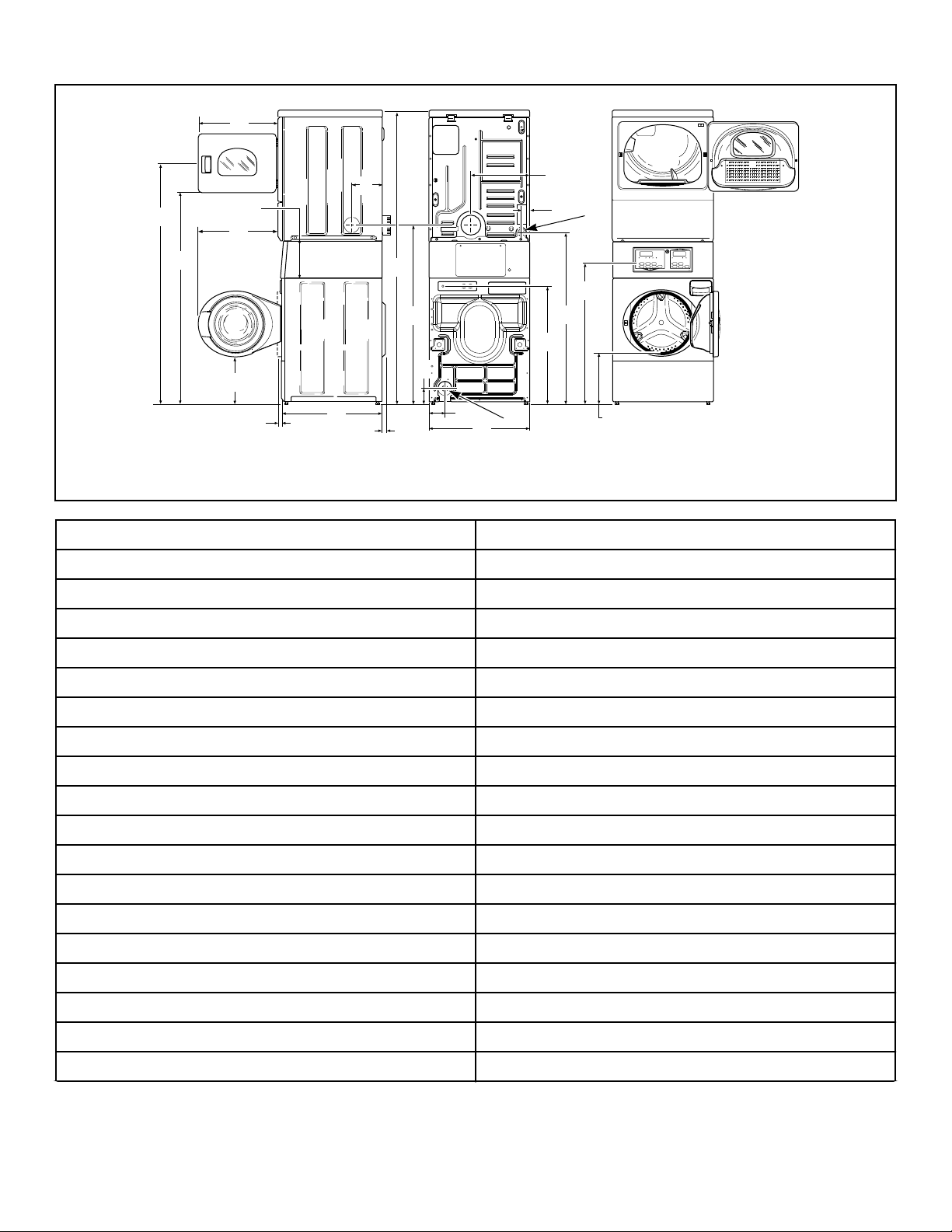
Dimensions
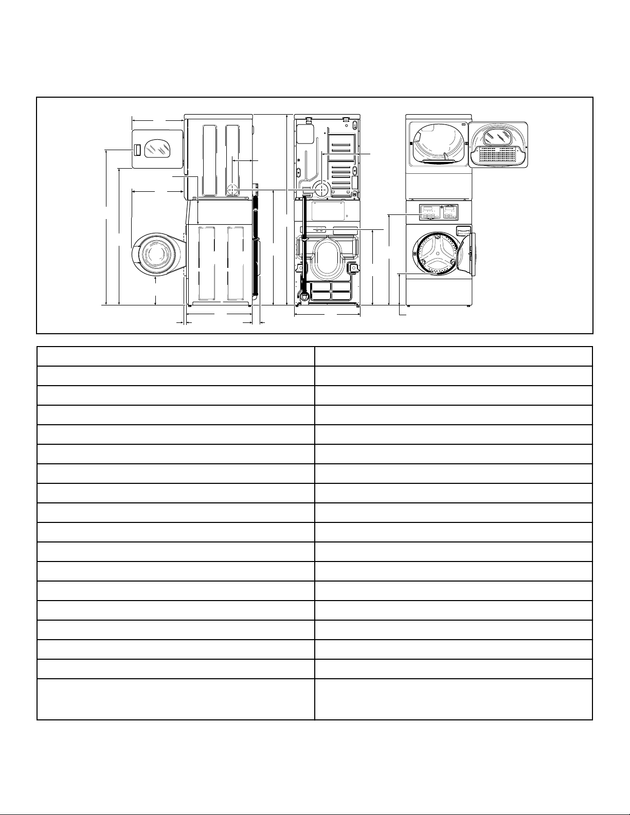
Electric Models Equipped With Drain Hose
SWD1023N_SVG
Q
P
O
N
I
M
L
K
J
H
G
F
E
D
C
B
A
A * 66.06 in. [1678 mm]
B * 56.97 in. [1447 mm]
C 23.5 in. [597 mm]
D 8.375 in. [213 mm]
E 24 in. [610 mm]
F 8 in. [203 mm]
G 15.4 in. [391 mm]
H * 36.9 in. [938 mm]
I ** * 14.6 in. [371 mm]
J * 32 in. [813 mm]
K 26.875 in. [683 mm]
L * 78.17 in. [1986 mm]
M * 46.62 in. [1184 mm]
N 2.04 in. [52 mm]
O 27.73 in. [704 mm]
P (with door closed) 1.5 in. [38 mm]
Q * 13.1 in. [333 mm]
NOTE: Exhaust openings are 4 inch [102 mm] metal
ducting.
* With leveling legs turned into base.
** For ADA compliance turn legs out from base 0.5 inches.
Dimensions
©
Copyright, Alliance Laundry Systems LLC -
DO NOT COPY or TRANSMIT
10 Part No. 805420ENR4
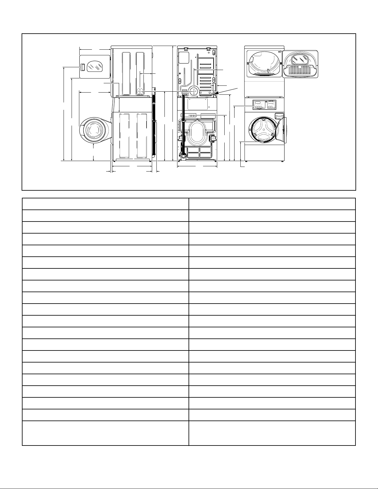
Gas Models Equipped With Drain Hose
SWD1024N_SVG
Q
S
PR
O
N
M
L
I
K
J
H
G
F
E
D
C
B
A
1
1. 3/8 in. NPT Gas Connection
A *66.06 in. [1678 mm]
B *56.97 in. [1447 mm]
C 23.5 in. [597 mm]
D 8.375 in. [213 mm]
E 24 in. [610 mm]
F 8 in. [203 mm]
G 15.4 in. [391 mm]
H 2.3 in. [59 mm]
I *36.9 in. [938 mm]
J ** *14.6 in. [371 mm]
K *44.87 in. [1140 mm]
L *32 in. [813 mm]
M 26.875 in. [683 mm]
N *78.17 in. [1986 mm]
O *46.62 in. [1184 mm]
P 2.04 in. [52 mm]
Q 27.73 in. [704 mm]
R (with door closed) 1.5 in. [38 mm]
S *13.1 in. [333 mm]
NOTE: Exhaust openings are 4 inch [102 mm] metal
ducting.
* With leveling legs turned into base.
** For ADA compliance turn legs out from base 0.5 inches.
Dimensions
©
Copyright, Alliance Laundry Systems LLC -
DO NOT COPY or TRANSMIT
11 Part No. 805420ENR4
Gas Models Equipped With Gravity Drain
SWD1028N_SVG
Q
U
S
P
R
T
O
N
M
L
I
K
J
H
G
F
E
D
C
B
A
1
2
1. 3/8 in. NPT Gas Connection
2. 1.5 in. [38 mm] Inside Diameter; 1.86 in. [47 mm] Outside Diameter
A *66.06 in. [1678 mm]
B *56.97 in. [1447 mm]
C 23.5 in. [597 mm]
D 8.375 in. [213 mm]
E 24 in. [610 mm]
F 8 in. [203 mm]
G 15.4 in. [391 mm]
H 2.3 in. [60 mm]
I *36.9 in. [938 mm]
J ** *14.6 in. [371 mm]
K *44.87 in. [1140 mm]
L *32 in. [813 mm]
M 26.875 in. [683 mm]
N 4.2 in. [107 mm]
O *4.1 in. [104 mm]
P *46.62 in. [1184 mm]
Q *78.17 in. [1986 mm]
R 2.04 in. [52 mm]
S 27.73 in. [704 mm]
Table continues...
Dimensions
©
Copyright, Alliance Laundry Systems LLC -
DO NOT COPY or TRANSMIT
12 Part No. 805420ENR4

T (with door closed) 1.5 in. [38 mm]
U *13.1 in. [333 mm]
NOTE: Exhaust openings are 4 inch [102 mm] metal
ducting.
* With leveling legs turned into base.
** For ADA compliance turn legs out from base 0.5 inches.
NOTE: Gas models cannot be vented out left side of
cabinet because of burner housing.
IMPORTANT: The dryer should have sufficient clear-
ance around it for needed ventilation and for the ease
of installation and servicing. For maximum drying per-
formance, we recommend that more clearance be al-
lowed around the dryer than the clearances that are
listed throughout this manual.
Dimensions
©
Copyright, Alliance Laundry Systems LLC -
DO NOT COPY or TRANSMIT
13 Part No. 805420ENR4
Installation
Before You Start
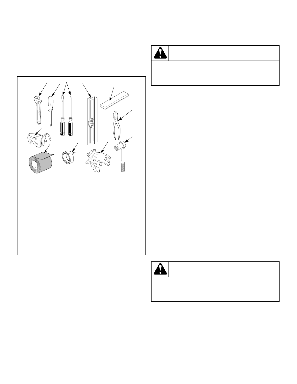
Tools
For most installations, the basic tools you will need are:
SWD1021N_SVG
11
10
9
8
4
3
2
1
6
7
5
1. Wrench
2. 1/4 inch Driver
3. Screwdriver
4. Level
5. Wood Block
6. Pliers
7. 5/16 Inch Socket Wrench
8. Gloves
9. Teflon Tape (Gas Models)
10. Duct Tape
11. Safety Glasses
Figure 1
NOTE: An 8 in. [20.32 cm] coin drawer is required for
coin operated models.
NOTE: If the unit is delivered on a cold day (below
freezing), or is stored in an unheated room or area dur-
ing the cold months, do not attempt to operate it until
the unit has had a chance to warm up.
NOTE: Some moisture in the wash drum is normal. Wa-
ter is used during testing at the manufacturer.
NOTE: This appliance is suitable for use in countries
having a warm, damp climate.
WARNING
Any disassembly requiring the use of tools must be
performed by a suitably qualified service person.
W299
Order of Installation Steps
The proper order of steps must be followed to ensure correct in-
stallation. Refer to the list below when installing your unit.
1. Position unit near area of installation.
2. Remove the shipping materials.
3. Connect the fill hoses.
4. For non-gravity drain models, connect the drain hose to the
drain receptacle.
5. For gravity drain models, connect the drain outlet to the drain
system.
6. For gas models only, connect the gas supply pipe. Check for
gas leaks.
7. For electric models only, connect the electrical plug.
8. Connect dryer to exhaust system.
9. Position and level the unit.
10. Wipe out inside of washer and dryer drums.
11. Plug in the washer and dryer.
12. Recheck steps.
13. Start and run the dryer in a heat setting to verify dryer is heat-
ing.
Position Unit Near Installation Area
Move unit so that it is within 4 feet [1.2 meters] of the desired
area of installation.
CAUTION
Washer and dryer are not designed to be operated as
separated, side-by-side units.
W187
NOTE: For best performance and to minimize vibration
or movement, install washer on a solid, sturdy and lev-
el floor. Some floors may need to be reinforced, espe-
cially on a second floor or over a basement. Do not in-
stall the washer on carpeting, soft tile or other weakly
supported structures.
Installation
©
Copyright, Alliance Laundry Systems LLC -
DO NOT COPY or TRANSMIT
14 Part No. 805420ENR4
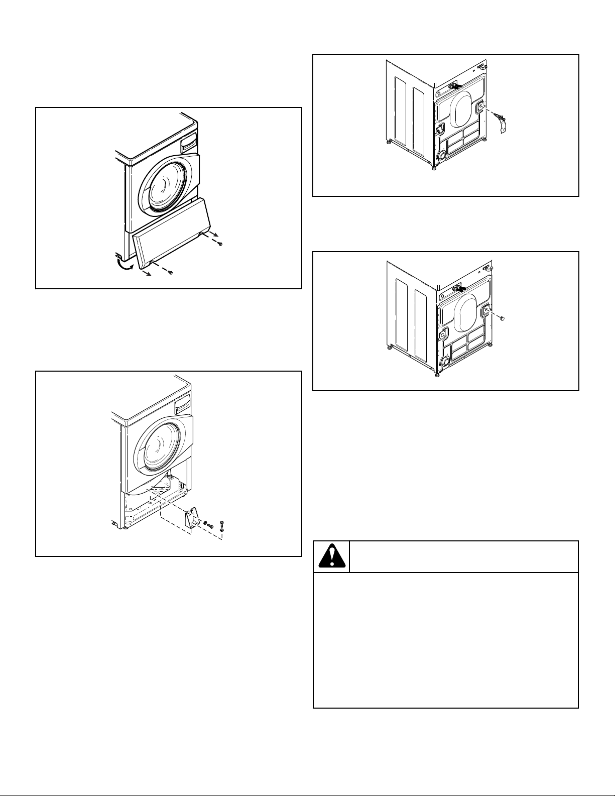
Remove Shipping Materials
1. Remove two screws at bottom of front access panel. Rotate
bottom of panel out and remove panel.
FLW2378N_SVG
Figure 2
2. Remove two 9/16 inch bolts and washers holding shipping
brace to weight.
3. Remove two 9/16 inch bolts and washers holding shipping
brace to washer base and remove brace.
FLW2296N_SVG1
Figure 3
4. Go to rear of washer and pull label from rear shipping bolts.
5. Remove two 9/16 inch bolts. Unscrew each bolt while apply-
ing forward pressure just until bolt stops unthreading. Work
each bolt and spacer out by hand using a circular motion.
NOTE: Avoid backing bolts out completely or
spacers might fall into cabinet.
FLW2297N_SVG1
Figure 4
6. Insert two plugs included in accessories bag into rear shipping
bolt holes.
FLW2358N_SVG
Figure 5
7. Replace front access panel.
8. Save all shipping materials. They must be reinstalled any time
washer is moved more than four feet.
IMPORTANT: Do not lift or transport unit from front
or without shipping materials installed. Refer to the
Maintenace section for proper instructions on rein-
stalling the shipping materials.
Connect Fill Hoses
WARNING
Under certain conditions, hydrogen gas may be pro-
duced in a hot water system that has not been used
for two weeks or more. HYDROGEN GAS IS EXPLO-
SIVE. If the hot water system has not been used for
such a period and before using the washer, turn on
all hot water faucets and let the water flow from each
for several minutes. This will release any accumulat-
ed hydrogen gas. The gas is flammable. Do not
smoke or use an open flame during this time.
W029
Installation
©
Copyright, Alliance Laundry Systems LLC -
DO NOT COPY or TRANSMIT
15 Part No. 805420ENR4
Water Supply Requirements
Water supply faucets must fit standard 3/4 inch [19 mm] female
garden hose couplings. DO NOT USE SLIP-ON OR CLAMP-
ON CONNECTIONS.
NOTE: Water supply faucets should be readily accessi-
ble to permit turning them off when washer is not being
used.
Recommended cold water temperature is 50° to 75° Fahrenheit
[10° to 24° Celsius]. Recommended maximum hot water temper-
ature is 125° Fahrenheit [51° Celsius]. Warm water is a mixture
of hot and cold water. Warm water temperature is dependent upon
the water temperature and the pressure of both the hot and cold
water supply lines.
WARNING
To prevent personal injury, avoid contact with inlet
water temperatures higher than 125° Fahrenheit [51°
Celsius] and hot surfaces.
W748
Maximum flow rate for all water temperatures is 2.5 gallons per
minute [9.46 liters per minute] ± 15%.
Water pressure must be a minimum of 20 to a maximum of 120
pounds per square inch [minimum of 138 to a maximum of 827
kPa] static pressure measured at the faucet.
NOTE: Water pressure under 20 pounds per square
inch [138 kPa] will cause an extended fill time in the
washer and may not properly flush out the detergent
dispenser.
Turn on the water supply faucets and flush the lines for approxi-
mately two minutes to remove any foreign materials that could
clog the screens in the water mixing valve. This is especially im-
portant when installing your washer in a newly constructed or
renovated building. Build-up may have occurred during construc-
tion.
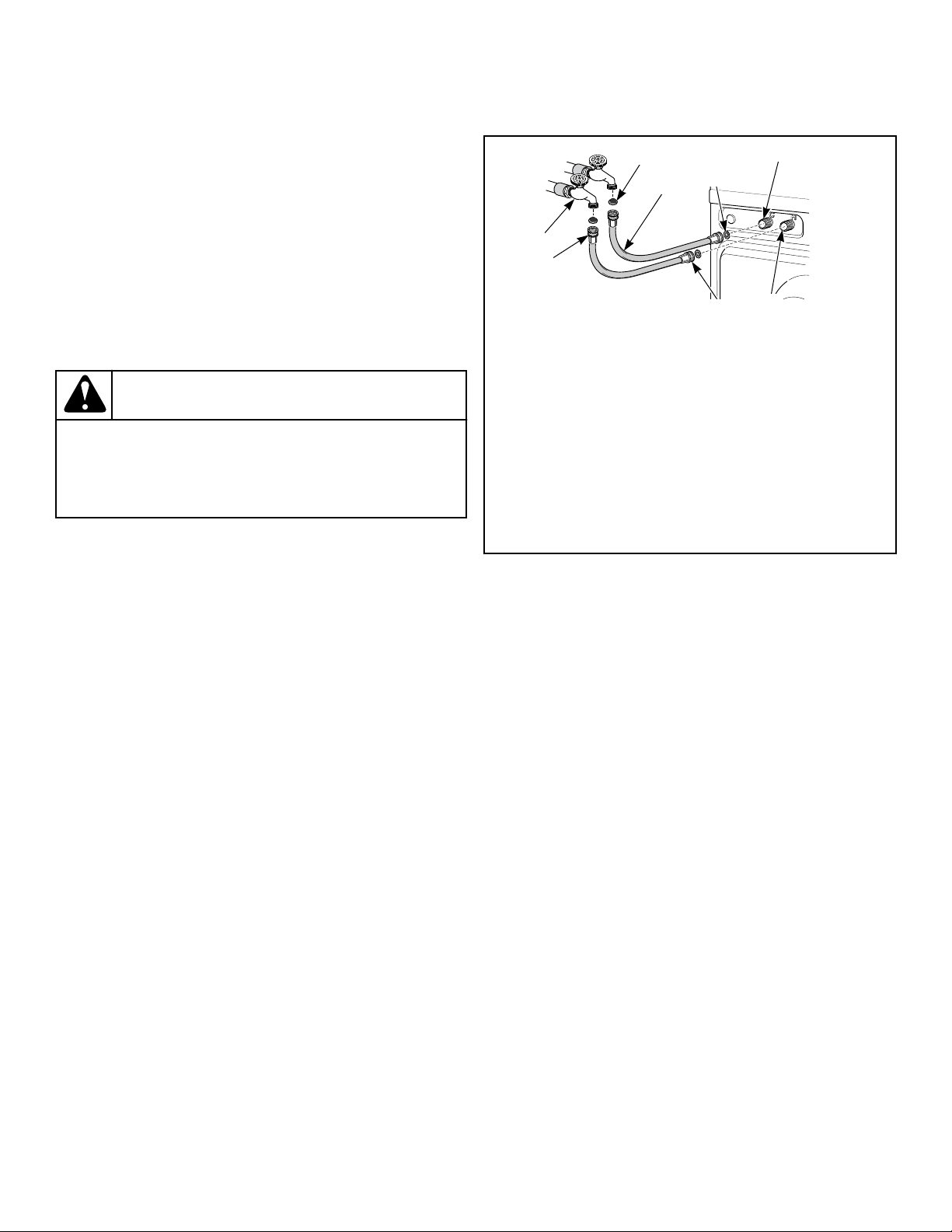
Connecting Hoses
1. Insert rubber washers and filter screens (from accessories
bag) in water fill hose couplings (two hoses supplied with
washer). The filter screen must be facing outward.
2. Connect fill hose couplings with filter screens to water supply
faucets.
3. Connect the other hose couplings to the hot and cold valve
connections at the rear of the washer.
4. Thread hose couplings onto valve connections finger tight.
Then turn 1/4 turn with pliers.
IMPORTANT: DO NOT cross thread or overtighten
couplings. This will cause them to leak.
5. Turn water on and check for leaks.
6. If leaks are found, retighten the hose couplings.
7. Continue tightening and rechecking until no leaks are found.
FLW2304N_SVG1
COLD
HOT
1
4
5
6
7
8
2
3
1. Filter Screen (Screen must be facing outward)
2. Fill Hose
3. Plain Rubber Washer
4. Cold Water Connection
5. Hot Water Connection
6. Install this end of hose to valve connections at rear of
washer
7. Install this end of hose to water supply faucet
8. Faucet
Figure 6
IMPORTANT:
Hoses and other rubber parts deteriorate after extend-
ed use. Hoses may develop cracks, blisters or material
wear from the temperature and constant high pressure
they are subjected to.
All hoses should be checked on a monthly basis for
any visible signs of deterioration. Any hose showing
the signs of deterioration listed above should be re-
placed immediately. All hoses should be replaced ev-
ery five years.
IMPORTANT: Turn off water supply faucets after check-
out and demonstration. Owner should turn off water
supply whenever there will be an extended period of
non-use.
NOTE: Longer fill hoses are available (as optional
equipment at extra cost) if the hoses (supplied with the
washer) are not long enough for the installation. Order
hoses as follows:
• No. 20617 Fill Hose: 8 feet [2.44 m]
• No. 20618 Fill Hose: 10 feet [3.05 m]
Risers
Risers (or air cushions) may have to be installed if the pipes
knock or pound when flow of water stops. The risers are more ef-
ficient when installed as close as possible to the water supply fau-
cets. Refer to Figure 7 .
Installation
©
Copyright, Alliance Laundry Systems LLC -
DO NOT COPY or TRANSMIT
16 Part No. 805420ENR4
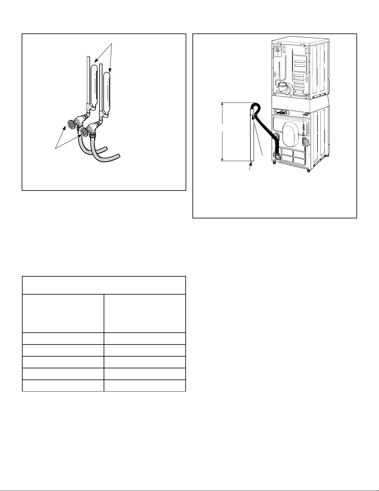
W005I_SVG
2
1
1. Risers (Air cushions)
2. Water Supply Faucets
Figure 7
Non-Gravity Drain Models - Connect
Drain Hose to Drain Receptacle
Remove the drain hose from its shipping position on the rear of
the washer by removing the shipping tape.
IMPORTANT: Drain receptacle must be capable of han-
dling a minimum of 1-3/8 inch [35 mm] outside diame-
ter drain hose.
Drain Flow Rate
Drain Height
Flow Rate
gallons per minute [lit-
ers per minute]
3 ft. [0.9 m] 8.6 [32.7]
5 ft. [1.5 m] 6.8 [25.9]
6 ft. [1.8 m] 6.0 [22.7]
7 ft. [2.1 m] 5.1 [19.5]
8 ft. [2.4 m] 4.0 [15.2]
Standpipe Installation
1. Place the drain hose into the standpipe.
2. Remove the beaded tie-down strap from accessories bag and
place around standpipe and drain hose and tighten strap to
hold hose to standpipe. Refer to Figure 8 . This will prevent
the drain hose from dislodging from drain receptacle during
use.
SWD1026N_SVG
2
3
1
1. 24 to 36 in. [610 to 914 mm] Recommended Height
2. Beaded strap from accessory bag
3. Standpipe 2 in. [51 mm] or 1-1/2 in. [40 mm]
Figure 8
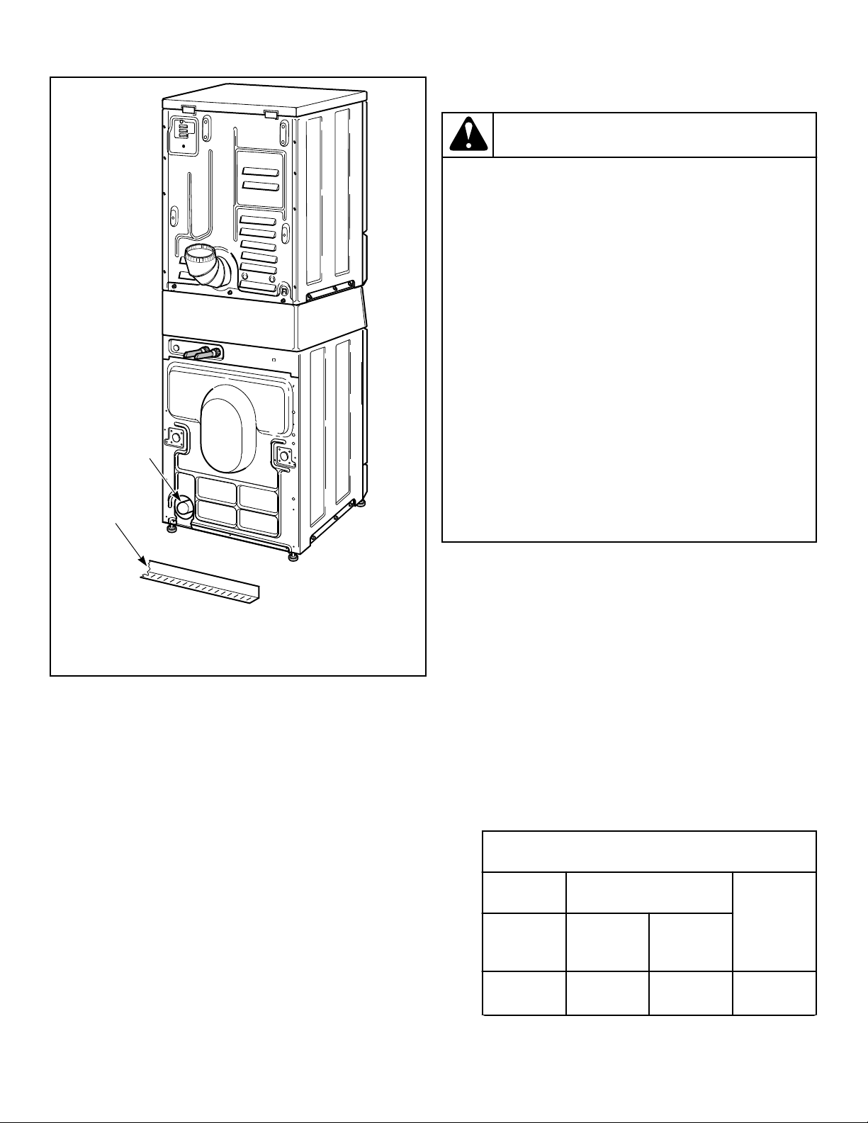
Gravity Drain Models - Connect Drain
Outlet to Drain System
Maximum flow rate is 24 gallons/minute [90.8 liters/minute].
Flow rates will vary with load type.
1. Remove drain fitting (4 inches [102 mm] long) and hose
clamp from accessories bag. Insert drain fitting into drain out-
let hose. Clamp hose and fitting.
2. Connect the drain fitting to a vented drain system using a
flexible connection (obtain locally). Inside diameter of fitting
is 1.53 in. [39 mm] and outside diameter is 1.66 in. [42 mm].
3. The drain system must be vented to prevent an air lock or si-
phoning.
IMPORTANT: Increasing the drain hose length, in-
stalling elbows, or causing bends will decrease
drain flow rates and increase drain times, impairing
machine performance.
Installation
©
Copyright, Alliance Laundry Systems LLC -
DO NOT COPY or TRANSMIT
17 Part No. 805420ENR4
SWD1002N_SVG
2
1
1. Drain Trough
2. Drain Outlet Hose
Figure 9
Gas Dryers - Connect Gas Supply Pipe
WARNING
To reduce the risk of gas leaks, fire or explosion:
• The dryer must be connected to the type of gas
as shown on nameplate located in the door re-
cess.
• Use a new flexible stainless steel connector.
• Use pipe joint compound insoluble in L.P. (Lique-
fied Petroleum) Gas, or Teflon tape, on all pipe
threads.
• Purge air and sediment from gas supply line be-
fore connecting it to the dryer. Before tightening
the connection, purge remaining air from gas line
to dryer until odor of gas is detected. This step is
required to prevent gas valve contamination.
• Do not use an open flame to check for gas leaks.
Use a non-corrosive leak detection fluid.
• Any disassembly requiring the use of tools must
be performed by a suitably qualified service per-
son.
W316
1. Make certain your dryer is equipped for use with the type of
gas in your laundry room. Dryer is equipped at the factory for
Natural Gas with a 3/8 inch NPT gas connection.
NOTE: The gas service to a gas dryer must conform
with the local codes and ordinances, or in the ab-
sence of local codes and ordinances, with the latest
edition of the National Fuel Gas Code ANSI Z223.1/
NFPA 54 or the CAN/CSA-B149.1 Natural Gas and
Propane Installation Code.
Natural Gas, 1000 Btu/ft
3
[37.3 MJ/m
3
], service must be supplied
at minimum 5.0 inch water column pressure to maximum 10.5
inch water column pressure.
For proper operation at altitudes above 2000 feet [610 m] the nat-
ural gas valve spud orifice size must be reduced to ensure com-
plete combustion. Refer to Table 1 .
Natural Gas Altitude Adjustments
Altitude Orifice Size
Part
Numberfeet [m] #
inches
[mm]
2,000 [610] 41 0.0960
[2.44]
D503776
Table 1 continues...
Installation
©
Copyright, Alliance Laundry Systems LLC -
DO NOT COPY or TRANSMIT
18 Part No. 805420ENR4
Natural Gas Altitude Adjustments
Altitude Orifice Size
Part
Numberfeet [m] #
inches
[mm]
3,000 [915] 42 0.0935
[2.37]
D503777
5,500
[1,680]
43 0.0890
[2.26]
D503778
7,000
[2,135]
44 0.0860
[2.18]
58719
9,000
[2,745]
45 0.0820
[2.08]
D503779
10,500
[3,200]
46 0.0810
[2.06]
D503780
Table 1
2. Remove the shipping cap from the gas connection at the rear
of the dryer. Make sure you do not damage the pipe threads
when removing the cap.
NOTE: If gas supply connection is British Standard
Pipe Tapered thread (BSPT), order 44178804 brass
female NPT (FPT) to male BSPT gas pipe thread
adapter, available at extra cost.
3. Connect to gas supply pipe using thread sealant or Teflon
tape. Torque 90 - 175 inch-pounds [10.2 - 19.7 Nm].
NOTE: The connection of gas supply to the appli-
ance shall be made with a flexible hose suitable for
the appliance category in accordance with national
installation regulations of the country of destina-
tion. If in doubt contact the dryer distributor or man-
ufacturer.
NOTE: When connecting to a gas line, an equipment
shut-off valve in accordance with the National Fuel
Gas Code, ANSI Z223.1/NFPA 54 and the Natural
Gas and Propane Installation Code, CSA B149.1
must be installed within 6 feet [1.8 m] of the dryer.
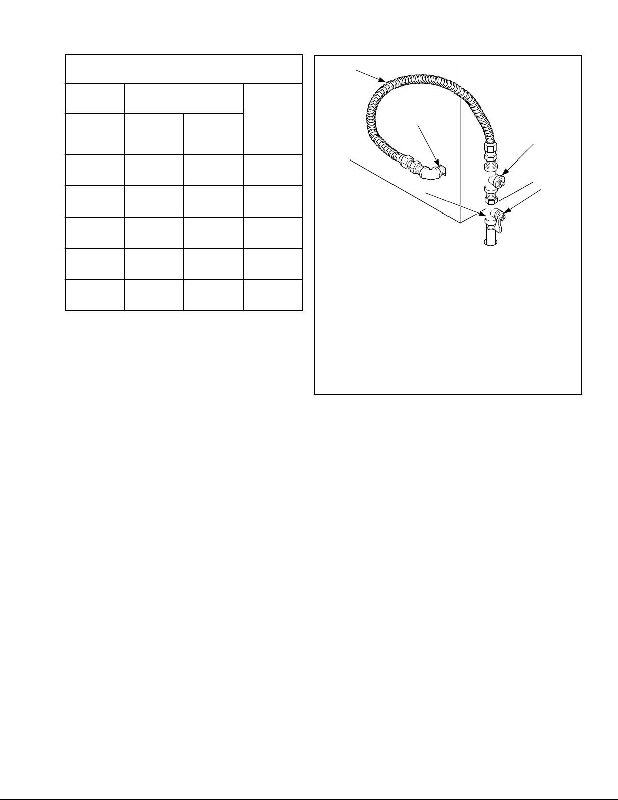
An 1/8 in. NPT pipe plug must be installed as shown
for checking inlet pressure. Refer to Figure 10 .
D233I_SVG
2
3
4
1
5
1.
New Stainless Steel Flexible Connector – (Use design
CSA certified connector) Use only if allowed by local co-
des
2. 1/8 in. NPT Pipe Plug
3. Equipment Shut-Off Valve
4. Black Iron Pipe:
Shorter than 20 ft. [6.1 m] – Use 3/8 in. [9.5 mm] pipe.
Longer than 20 ft. [6.1 m] – Use 1/2 in. [12.7 mm] pipe.
5. 3/8 in. NPT Gas Connection
Figure 10
4. Tighten all connections securely but don't overtighten to avoid
breaking or bending the gas valve bracket. Turn on gas and
check all pipe connections (internal & external) for gas leaks
with a non-corrosive leak detection fluid.
NOTE: The dryer and its appliance main gas valve must
be disconnected from the gas supply piping system
during any pressure testing of that system at test pres-
sures in excess of 1/2 psi [3.45 kPa]. Refer to Check
Heat Source.
NOTE: DO NOT connect the dryer to L.P. Gas Service
without converting the gas valve. Install L.P. Gas Con-
version Kit 458P3, available at extra cost.
L.P. (Liquefied Petroleum) Gas, 2500 Btu/ft.
3
[93.1 MJ/m
3
], serv-
ice must be supplied at 10 ± 1.5 inch water column pressure.
For proper operation at altitudes above 3500 feet [1070 m] the
L.P. gas valve spud orifice size must be reduced to ensure com-
plete combustion. Refer to Table 2 .
Installation
©
Copyright, Alliance Laundry Systems LLC -
DO NOT COPY or TRANSMIT
19 Part No. 805420ENR4
L.P. Altitude Adjustments
Altitude Orifice Size
Part No.feet [m] No.
inches
[mm]
3500 [1070] 54 0.0550 [1.40] D503785
7500 [2290] 55 0.0520 [1.32] 58755
11000 [3355] 56 0.0465 [1.18] D503786
Table 2
Electric Dryer Only - Connect Electrical
Plug
Dryer requires 120/240 Volt or 120/208 Volt, 60 Hertz, 3 or 4
wire electrical supply. Refer to serial plate for specific electrical
requirements.
IMPORTANT: Use only a new U.L. listed No. 10 (copper
wire only) three or four conductor power supply cord
kit rated 240 Volts (minimum) 30 Amperes and labeled
as suitable for use in a clothes dryer.
NOTE: The wiring diagram is located in the control cab-
inet.
WARNING
To reduce the risk of fire, electric shock, serious in-
jury or death, all wiring and grounding MUST con-
form with the latest edition of the National Electrical
Code, ANSI/NFPA 70, or the Canadian Electrical
Code, CSA C22.1, and such local regulations as
might apply. It is the customer’s responsibility to
have the wiring and fuses installed by a qualified
electrician to make sure adequate electrical power is
available to the dryer.
W521
Earth/Ground Information
This appliance must be properly connected to protective earth/
ground. In the event of malfunction or breakdown, the earth/
ground will reduce the risk of electric shock by providing a path
of least resistance for electric current.
The cord-kit must be equipped with a cord having an equipment-
earth/ground conductor and an earth/ground plug. The plug must
be plugged into an appropriate outlet that is properly installed and
connected to a protective earth/ground in accordance with all lo-
cal codes and ordinances.
WARNING
Improper connection of the equipment earth/ground
conductor can result in a risk of electric shock.
Check with a qualified electrician or service person if
you are in doubt as to whether the dryer is properly
connected to a protective earth/ground.
W886
Do not modify the plug provided with the cord-kit - if it will not
fit the outlet, have a proper outlet installed by a qualified electri-
cian.
The dryer has its own terminal block that must be connected to a
separate branch, 60 Hertz, single phase circuit, AC (alternating
current) circuit, fused at 30 Amperes (the circuit must be fused on
both sides of the line). Electrical service for the dryer should be
of maximum rated voltage (208 or 240 Volt, depending on heat-
ing element) listed on the serial plate. Do not connect dryer to
110, 115, or 120 Volt circuit.
Heating elements are available for field installation in dryers
which are to be connected to electrical service of different volt-
age than that listed on serial plate, such as 208 Volt.
NOTE: Branch circuit wire size requirements to laundry
room outlet are shown in table below.
Wire Length Wire
Less than 15 ft. [4.5 m] Listed No. 10 AWG Copper
wire only
Longer than 15 ft. [4.5 m] Listed No. 8 AWG Copper
wire only
Table 3
The power cord connection between wall receptacle and dryer
terminal block IS NOT supplied with dryer. Type of power cord
and gauge of wire must conform to local codes.
IMPORTANT: Use only a new U.L. listed No. 10 (copper
wire only) three or four conductor power supply cord
kit rated 240 Volts (minimum) 30 Amperes and labeled
as suitable for use in a clothes dryer.
Installation
©
Copyright, Alliance Laundry Systems LLC -
DO NOT COPY or TRANSMIT
20 Part No. 805420ENR4
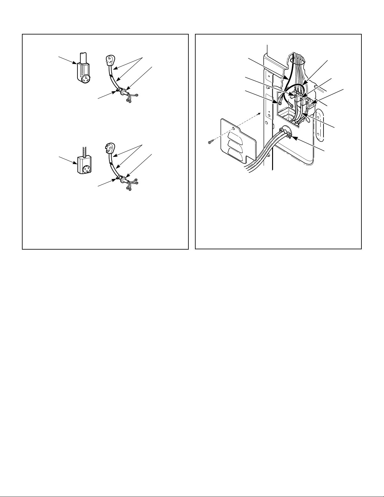
Three-Wire
D275I_SVG
3
2
1
4
Four-Wire
D006I_SVG
3
2
1
4
1. Typical Receptacle
2. Power Cord
3. Stain Relief Nut
4. Strain Relief
Figure 11
Three-Wire Connection
D679I_SVG
8
7
6
5
4
3
2
1
1. Ground Wire
2. Ground to Neutral Wire
3. Neutral Terminal
4. “L2” Terminal
5. Center Wire (Neutral)
6. Strain Relief (Not supplied with dryer)
7. Ground Screw
8. “L1” Terminal
Figure 12
Installation
©
Copyright, Alliance Laundry Systems LLC -
DO NOT COPY or TRANSMIT
21 Part No. 805420ENR4
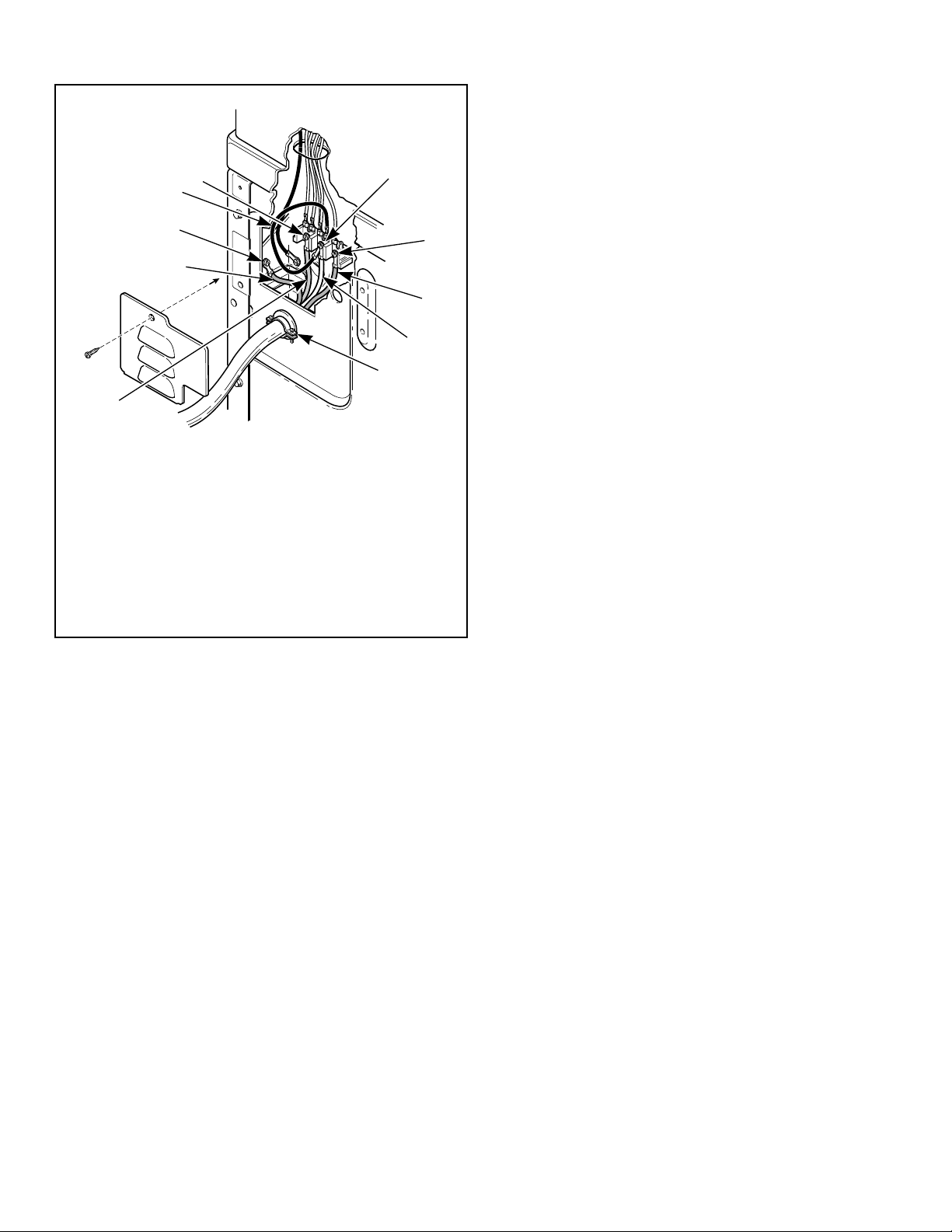
Four-Wire Connection
D680I_SVG
1
2
1
9
8
7
6
5
4
3
1. Ground Wire
2. Ground Screw
3. “L1” Terminal
4. Neutral Terminal
5. “L2” Terminal
6. Black Wire
7. White Wire (Neutral)
8. Strain Relief (Not supplied with dryer)
9. Red Wire
Figure 13
NOTE: Dryer is shown with access cover removed for
illustration purposes only. NEVER operate the dryer
with access cover removed.
Connecting Power Cord with Three-Wire Plug
NOTE: Four-wire cord is required for new branch-cir-
cuit installations, mobile homes or where codes do not
permit grounding through neutral.
NOTE: The power cord is NOT supplied with the elec-
tric dryer. Type of power cord and gauge of wire must
conform to local codes and instructions. The method
of wiring the dryer is optional and subject to local code
requirements.
NOTE: Connect the dryer to the power supply with the
MAXIMUM RATED VOLTAGE listed on the serial plate.
NOTE: Use COPPER WIRE only.
Shorter than 15 ft. (4.5 m) – use 10 AWG
Longer than 15 ft. (4.5 m) – use 8 AWG
Installation
©
Copyright, Alliance Laundry Systems LLC -
DO NOT COPY or TRANSMIT
22 Part No. 805420ENR4
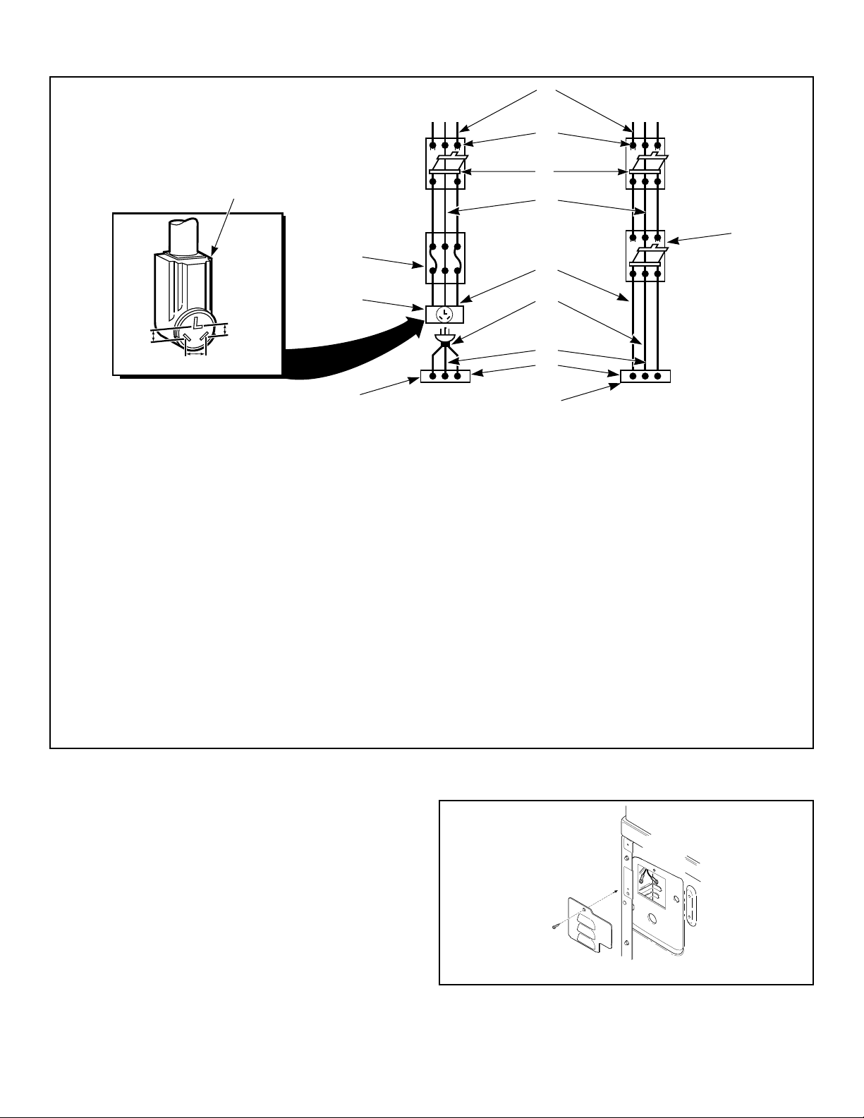
D816I_SVG
L1 L2 L1 L2
15
16
5
2
2
3
4
8
9
12
13
10
11
7
6
1
14
1. A typical 30-Amp Three-Wire Receptacle NEMA Type 10-30R
2. 120 ± 12 V.A.C.
3. 240 ± 12 V.A.C.
4. Intermediate Fuse Box (may be omitted if service entrance box is fused)
5. Wall Receptacle
6. Power Supply
7. 3-Wire Earth/Ground Neutral 120/240 Volt, 60 Hertz AC 1 Phase Service Entrance Switch Box (Refer to NOTE above)
8. 30 Ampere Fuses or Circuit Breaker
9. Neutral Wire
10. Metallic or Non-Metallic Sheathed Cable (Copper Wire Only)
11. Power Cord (Not supplied with dryer)
12. Neutral
13. Terminal Block in Dryer
14. Intermediate Shut-Off Box (may or may not be fused)
15. Direct Connection
16. Power Cord Connection
Figure 14
1. Disconnect power to dryer.
2. Remove access cover from rear of dryer.
D695I_SVG
Figure 15
Installation
©
Copyright, Alliance Laundry Systems LLC -
DO NOT COPY or TRANSMIT
23 Part No. 805420ENR4
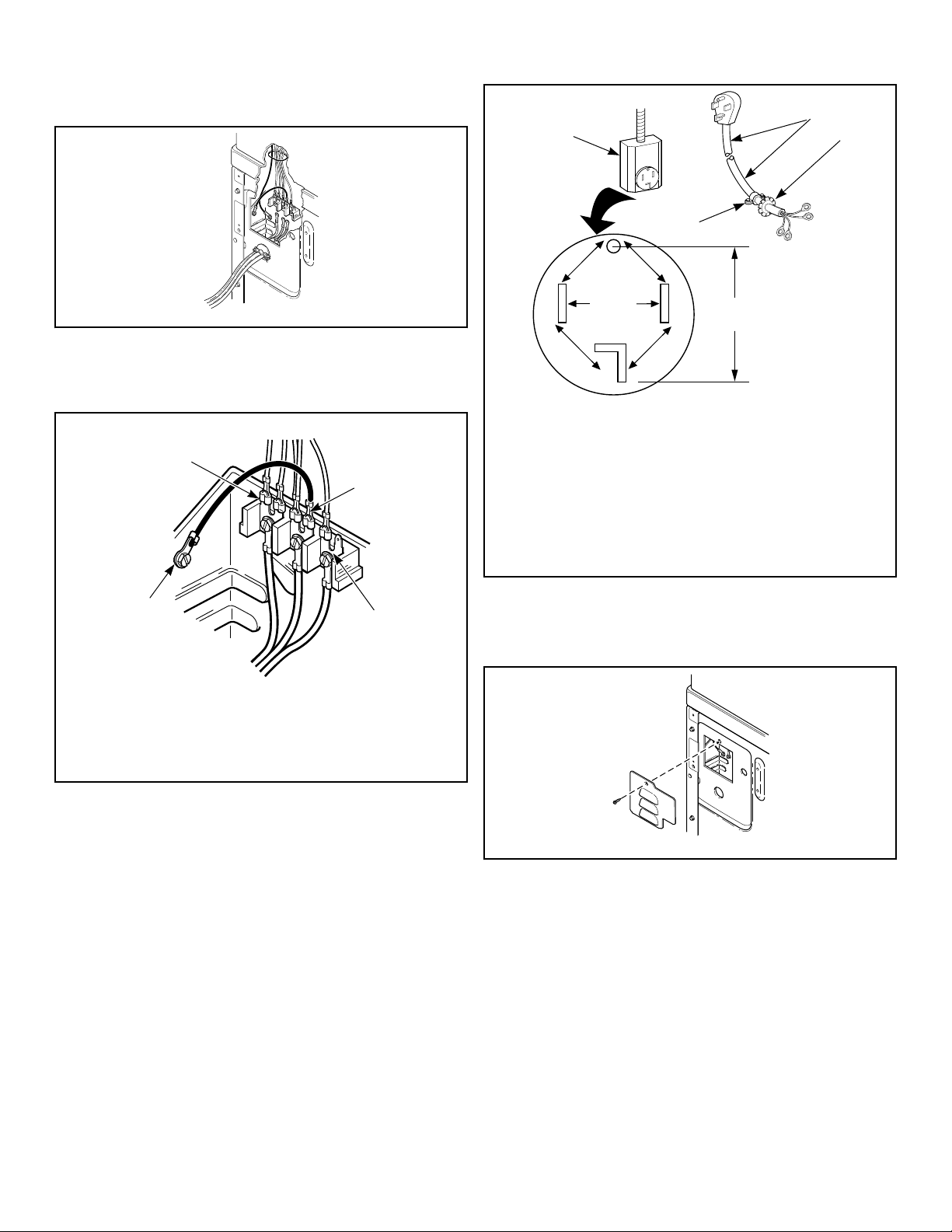
3. Use a strain relief and insert end of power cord through power
supply hole.
D696I_SVG
Figure 16
4. Use the three screws from the accessories bag to attach the
power cord wires to the terminal block. Refer to Figure 17 .
3-Wire Connection
DRY2508N_SVG
4
3
2
1
1. "L1" Terminal
2. Neutral Terminal
3. "L2" Terminal
4. Earth/Ground to Bulkhead
Figure 17
5. Using a screwdriver, tighten all screws firmly.
IMPORTANT: Failure to tighten these screws firmly
may result in wire failure at the terminal block.
6. Secure the strain relief to the power cord, or wires, where they
enter the dryer cabinet.
7. Check the continuity of the earth/ground connection before
plugging the cord into an outlet. Use an acceptable indicating
device connected to the center earth/ground pin of the plug
and the green screw on the back of the cabinet.
8. Reinstall access cover and screw.
Connecting Power Cord with Four-Wire Plug
NOTE: Four-wire cord is required for new branch-cir-
cuit installations, mobile homes or where codes do not
permit grounding through neutral.
DRY2016N_SVG
7
7
7
7
6
3
2
1
4
5
1. Typical Four-Wire Receptacle
2. Power Cord – Not Supplied with Dryer
3. Strain Relief Nut
4. Strain Relief
5. 0 V.A.C.
6. 240 ± 12 V.A.C.
7. 120 ± 12 V.A.C.
Figure 18
1. Disconnect power to dryer.
2. Remove access cover from rear of dryer.
DRY2467N_SVG
Figure 19
3. Remove earth/ground screw from earth/ground to neutral wire
and save for use in Step 5. Earth/ground to neutral wire will
be attached to the neutral terminal in Step 6.
Installation
©
Copyright, Alliance Laundry Systems LLC -
DO NOT COPY or TRANSMIT
24 Part No. 805420ENR4
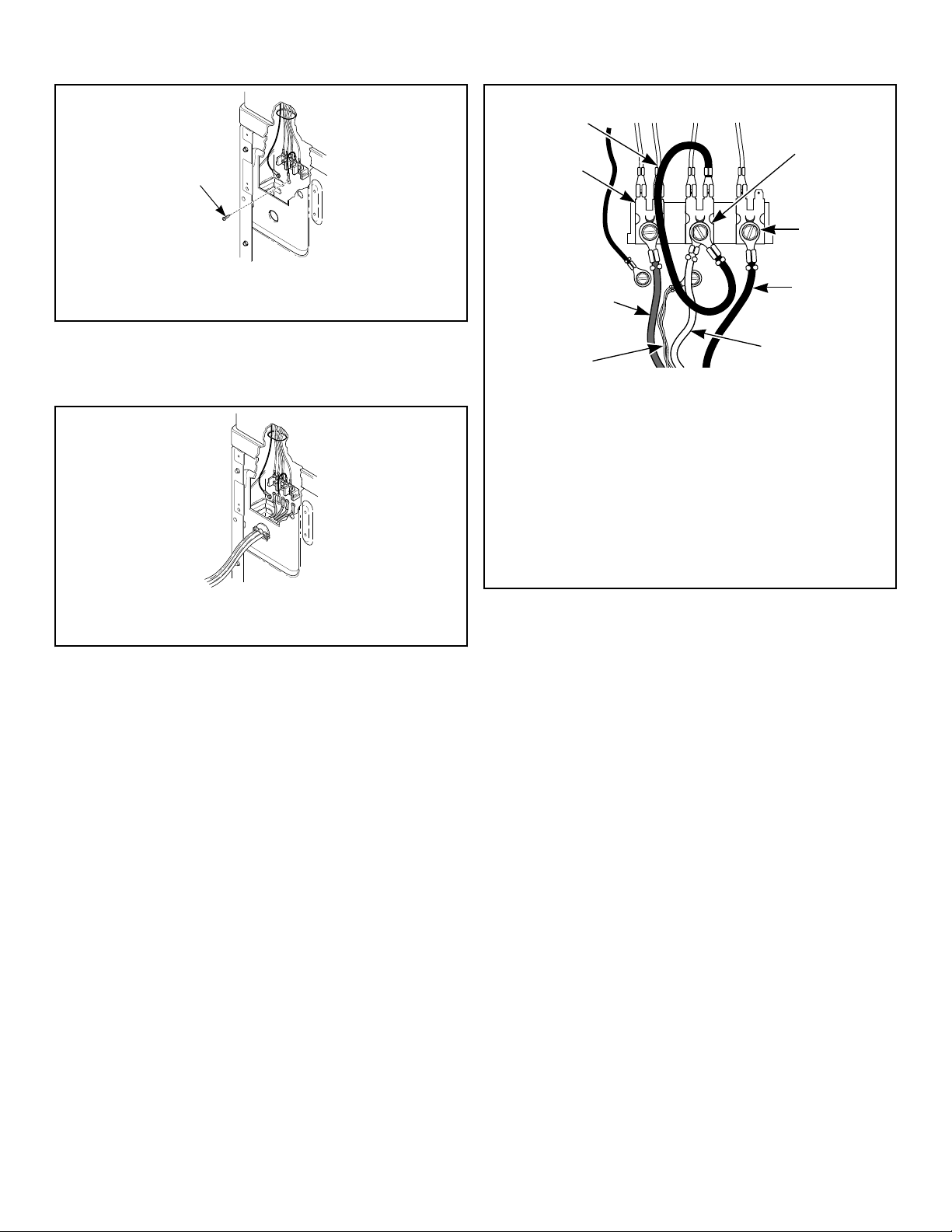
DRY2468N_SVG
1
1. Earth/Ground Screw
Figure 20
4. Use a strain relief and insert end of power cord through power
supply hole.
DRY2469N_SVG
1. Strain Relief
Figure 21
5. Attach power cord earth/ground (green) wire to rear bulkhead
using earth/ground screw removed in Step 3.
4-Wire Connection
DRY2482N_SVG
1
2
3
4
5
6
7
8
1. Neutral Terminal
2. “L2” Terminal
3. Black
4. White
5. Earth/Ground
6. Red
7. “L1” Terminal
8. Earth/Ground to Neutral Wire
Figure 22
6. Use the three screws from the accessories bag to attach the re-
maining power cord wires to the terminal block as follows:
a. Red wire to “L1” terminal.
b. Black wire to “L2” terminal.
c. White wire to Neutral terminal.
NOTE: When installing the white wire, loop the free
eyelet end of the earth/ground to neutral wire (re-
moved in Step 3) and attach along with the white
wire to the neutral (center) terminal on the terminal
block.
7. Using a screwdriver, tighten all screws firmly.
IMPORTANT: Failure to tighten these screws firmly
may result in wire failure at the terminal block.
8. Secure the strain relief to the power cord, or wires, where they
enter the dryer cabinet.
9. Check the continuity of the earth/ground connection before
plugging the cord into an outlet. Use an acceptable indicating
device connected to the center earth/ground pin of the plug
and the green screw on the back of the cabinet.
10. Reinstall access cover and screw.
Installation
©
Copyright, Alliance Laundry Systems LLC -
DO NOT COPY or TRANSMIT
25 Part No. 805420ENR4
Connect Dryer Exhaust System
WARNING
To reduce the risk of fire and combustion gas accu-
mulation the dryer MUST be exhausted to the out-
doors.
W604
WARNING
To reduce the risk of fire and the accumulation of
combustion gases, DO NOT exhaust dryer air into a
window well, gas vent, chimney or enclosed, unven-
tilated area, such as an attic, wall, ceiling, crawl
space under a building or concealed space of a
building.
W045
WARNING
This gas appliance contains or produces a chemical
or chemicals which can cause death or serious ill-
ness and which are known to the State of California
to cause cancer, birth defects, or other reproductive
harm. To reduce the risk from substances in the fuel
or from fuel combustion, make sure this appliance is
installed, operated, and maintained according to the
instructions in this manual.
W115
WARNING
To reduce the risk of fire, DO NOT use plastic or thin
foil ducting to exhaust the dryer.
W354
WARNING
To reduce the risk of fire, the exhaust duct and
weather hood MUST be fabricated of a material that
will not support combustion. Rigid or flexible metal
pipe is recommended for a clothes dryer.
W048
WARNING
To reduce the risk of fire due to increased static
pressure, we do not recommend installation of in-
line secondary lint filters or lint collectors. If secon-
dary systems are mandated, frequently clean the
system to assure safe operation.
W749
IMPORTANT: Installing in-line filters or lint collectors
will cause increased static pressure. Failure to main-
tain the secondary lint system will decrease dryer effi-
ciency and will void machine warranty.
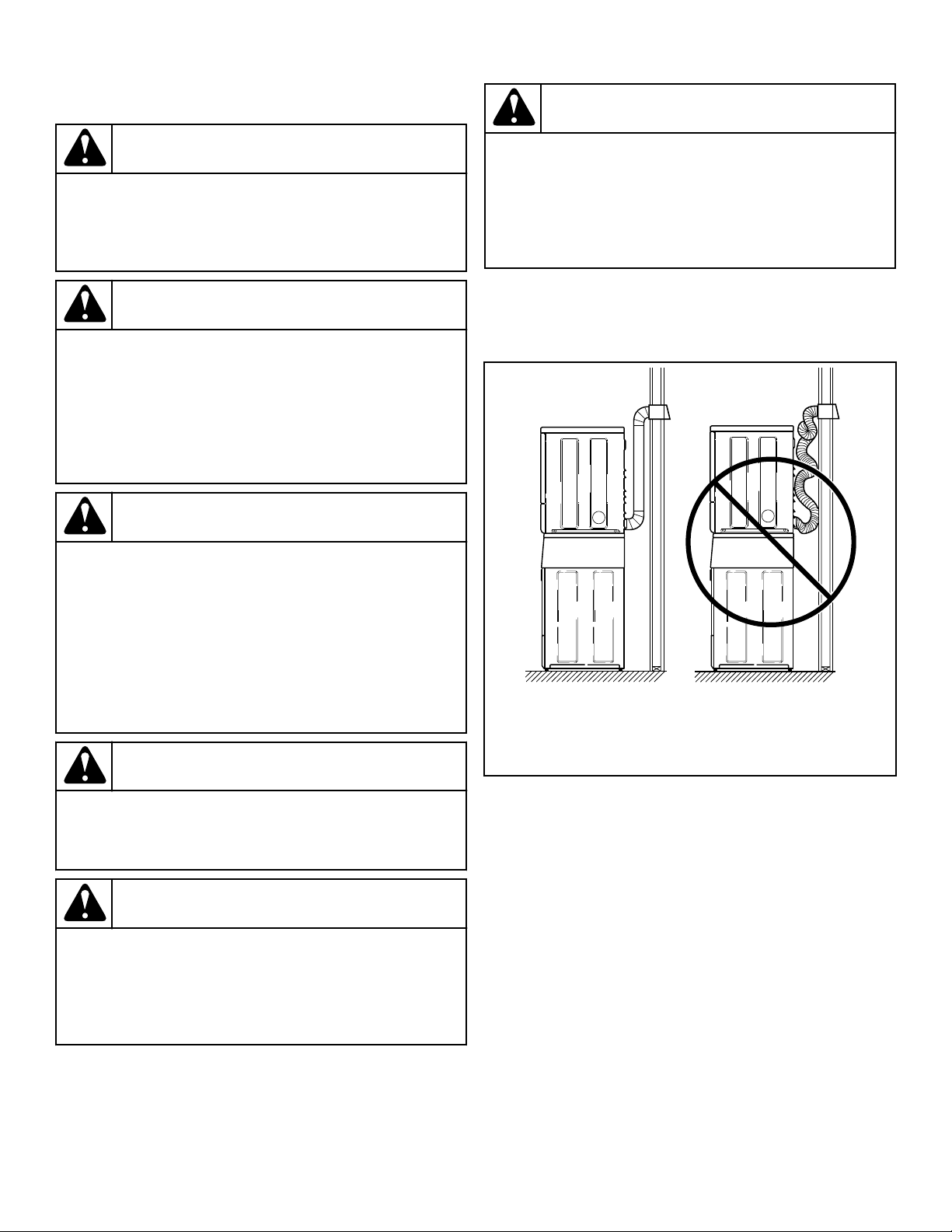
SWD997N_SVG
21
1. Correct
2. Incorrect
Figure 23
• DO NOT use plastic, thin foil or type B ducting. Rigid metal
duct is recommended.
• Locate dryer so exhaust duct is as short as possible.
• Be certain old exhaust ducts are cleaned before installing your
new dryer.
• Use 4 inch [102 mm] diameter rigid or flexible metal duct.
• The male end of each section of duct must point away from
the dryer.
• Use as few elbows as possible.
• Use of duct tape or pop-rivets on all seams and joints is rec-
ommended, if allowed by local codes. DO NOT use sheet
metal screws or fasteners on exhaust pipe joints which extend
into the duct and catch lint.
• Ductwork that runs through unheated areas must be insulated
to help reduce condensation and lint build-up on pipe walls.
• Install backdraft dampers in multi-dryer installations.
Installation
©
Copyright, Alliance Laundry Systems LLC -
DO NOT COPY or TRANSMIT
26 Part No. 805420ENR4
• In mobile home installations, dryer exhaust duct must be se-
cured to mobile home structure.
• Dryer exhaust duct MUST NOT terminate under mobile
home.
• Exhaust duct must not be connected to any other duct, vent, or
chimney.
• Dryer exhausts 220 cfm per unit (measured at back of dryer).
• DO NOT install flexible duct in concealed spaces, such as a
wall or ceiling.
• Static pressure in exhaust duct should not be greater than 0.6
inches water column [1.5 cm water column], measured with
manometer placed on exhaust duct 2 feet [610 mm] from dry-
er (check with dryer running and no load). In multi-dryer in-
stallations, all dryers connected to the main collector duct
should be operating when pressure is checked.
• Exhausting dryer in hard-to-reach locations can be done by
installing 521P3 Flexible Metal Vent Kit (available as option-
al equipment at extra cost).
• Sufficient make-up air must be supplied to replace the air ex-
hausted by the dryer. The free area of any opening for outside
air must be at least 40 in.
2
[25806 mm
2
] per unit.
• Energy efficient buildings with low air infiltration rates
should be equipped with an air exchanger that can accommo-
date on demand make-up air needs in the laundry room. These
devices can be obtained through your building contractor or
building material suppliers.
• Do not draw make-up air from a room containing a gas fired
water heater, a dry cleaner or a hair salon.
• Failure to exhaust dryer properly will void warranty.
• A dryer will dissipate 60 Btu/ft
2
[681,392 J/m
2
] of surface
area exposed to the conditioned air.
NOTE: Venting materials are not supplied with the dry-
er (obtain locally).
IMPORTANT: DO NOT block the airflow at the bottom of
the dryer’s front panel with laundry, rugs, etc. Blockage
will decrease airflow through the dryer, thus reducing
the efficiency of the dryer.
Exhaust Direction
The dryer can be exhausted to the outdoors through the back, left,
right or bottom of the dryer. EXCEPTION: Gas dryers cannot be
vented out the left side because of the burner housing.
Dryer is shipped from factory ready for rear exhaust.
Exhausting the dryer through sides or bottom can be accomplish-
ed by installing a Directional Exhaust Kit, 528P3, available as
optional equipment at extra cost.
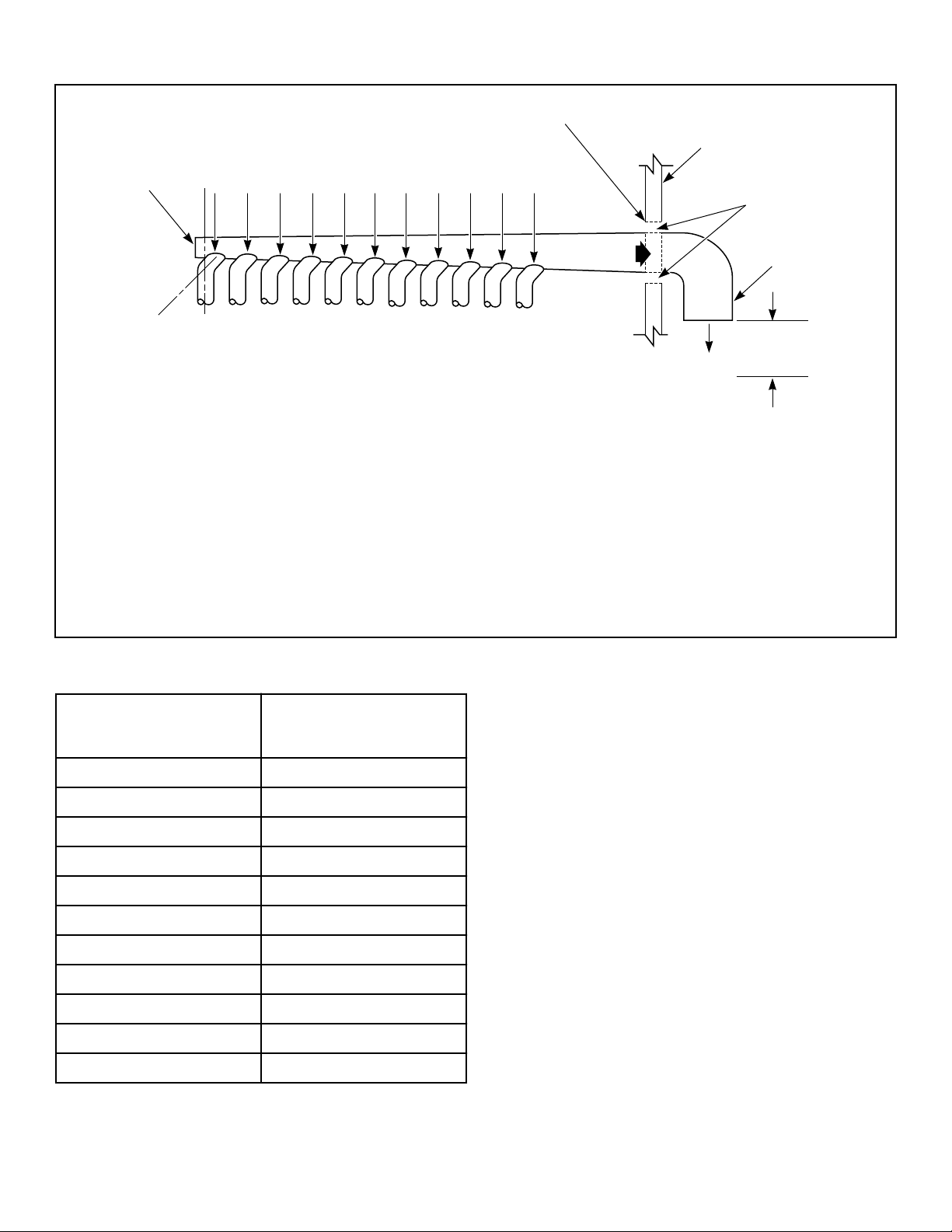
Exhaust System
For best drying results, recommended maximum length of ex-
haust system is shown in Table 4 .
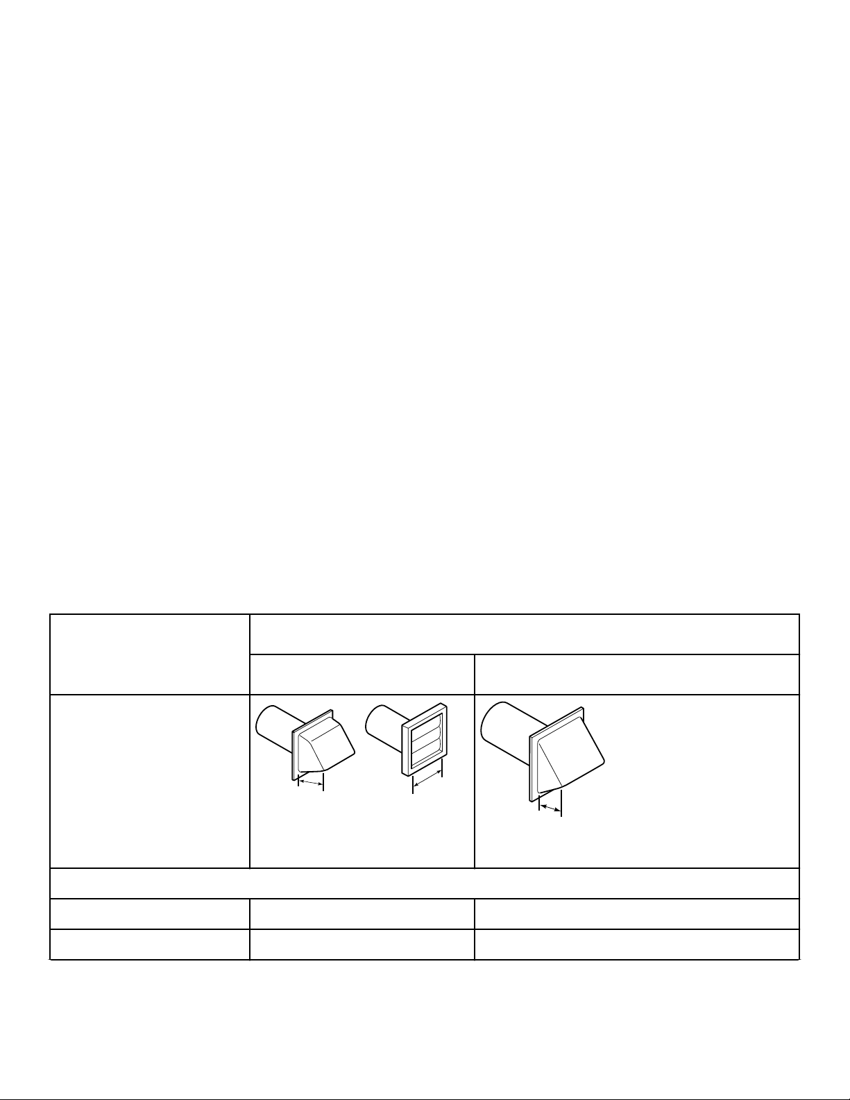
To prevent backdraft when dryer is not in operation, outer end of
exhaust pipe must have a weather hood with hinged dampers (ob-
tain locally).
NOTE: Weather hood should be installed at least 12 in-
ches [305 mm] above the ground. Larger clearances
may be necessary for installations where heavy snow-
fall can occur.
Number of 90° Elbows
Weather Hood Type
Recommended Use Only for Short Run Installations
D673I_SVG
1
1
1. 4 in. [102 mm]
D802I_SVG
1
1. 2.5 in. [64 mm]
Maximum length of 4 in. [102 mm] diameter rigid metal duct.
0 65 feet [19.8 m] 55 feet [16.8 m]
1 55 feet [16.8 m] 47 feet [14.3 m]
Table 4 continues...
Installation
©
Copyright, Alliance Laundry Systems LLC -
DO NOT COPY or TRANSMIT
27 Part No. 805420ENR4
Number of 90° Elbows
Weather Hood Type
Recommended Use Only for Short Run Installations
2 47 feet [14.3 m] 41 feet [12.5 m]
3 36 feet [11.0 m] 30 feet [9.1 m]
4 28 feet [8.5 m] 22 feet [6.7 m]
Table 4
NOTE: Deduct 6 feet [1.8 m] for each additional elbow.
NOTE: The maximum length of a 4 in. [102 mm] diame-
ter flexible metal duct must not exceed 7.87 ft. [2.4 m],
as required to meet UL2158, clause 7.3.2.A.
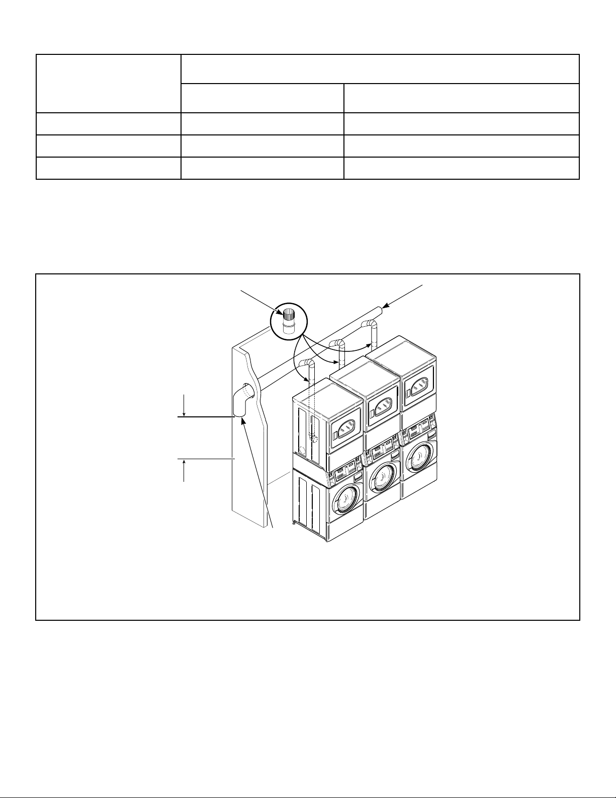
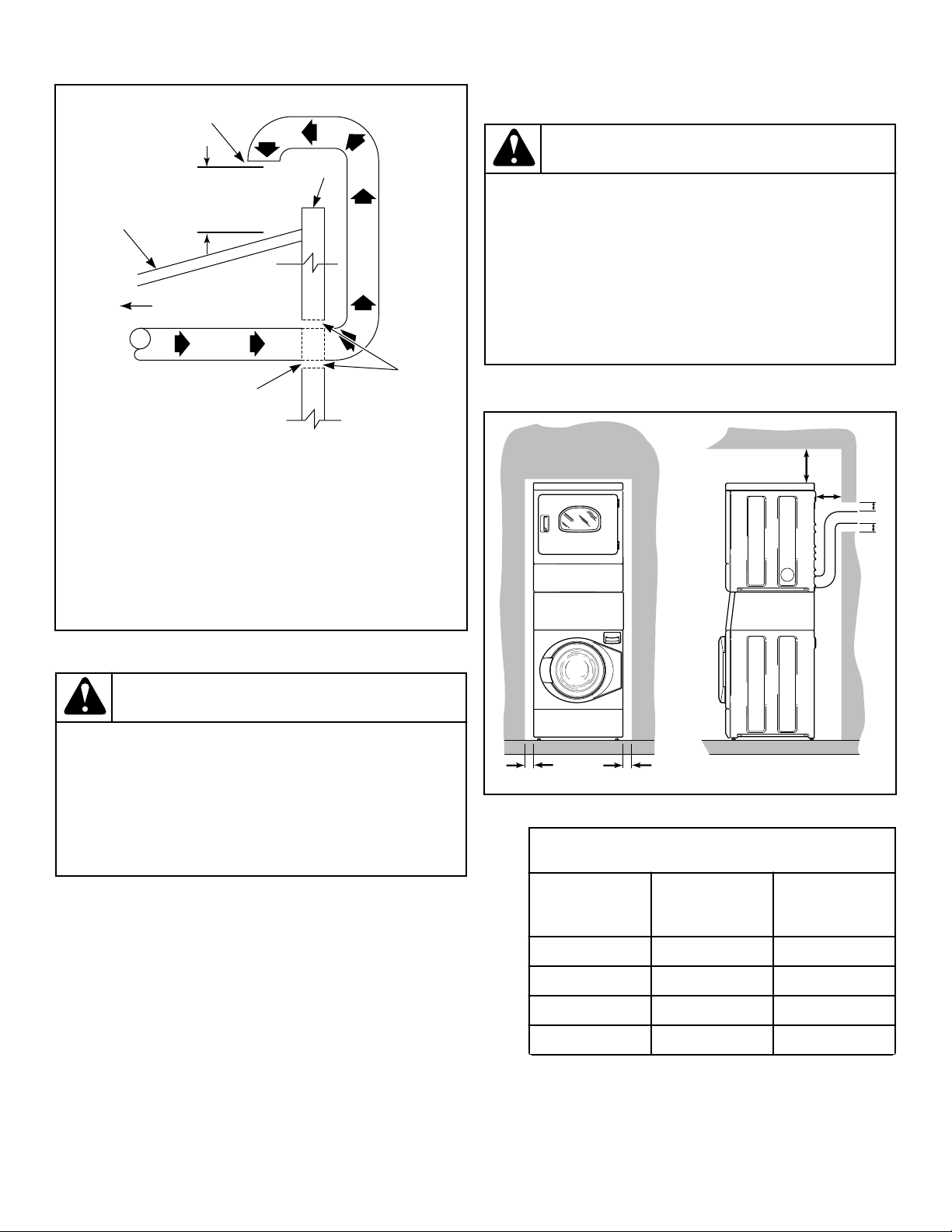
Multi-Dryer Installation Exhaust Requirements
Figure 24 shows a typical example of a multiple dryer installa-
tion. Note how each dryer has its own exhaust system vented to
the central exhaust duct.
SWD998N_SVG
4
3
2
1
1. 58786 Backdraft Damper (Available through your local authorized parts source)
2. Clean Out Cover (Must be provided). Inspect monthly.
3. Weather Hood or Sweep Elbow (No cap or screen)
4. 24 in. [610 mm] Minimum Clearance to Roof/Ground
Figure 24
Installation
©
Copyright, Alliance Laundry Systems LLC -
DO NOT COPY or TRANSMIT
28 Part No. 805420ENR4
Horizontal Exhaust Installation: Exhaust Air Flow Maximum Length of Duct 30 feet [9.1 m]
D686I_SVG
8
6
5
7
A B C D E F G H I J K
9
3
2
4
1
1. Where the exhaust duct pierces a combustible wall or ceiling, the opening must be sized per local codes.
2. Wall
3. 2 in. [50 mm] Minimum or Clearance per Local Codes
4. No Screen or Cap
5. 24 in. [610 mm] Minimum Clearance to Roof/Ground
6. Exhaust Outlet
7. Air Flow
8. 30 °
9. Clean Out Cover - Inspect Monthly
Figure 25
Duct Station
Minimum Diameter of
Collector Duct
A 4 inches [102 mm]
B 8 inches [203 mm]
C 9 inches [229 mm]
D 10 inches [254 mm]
E 11 inches [279 mm]
F 12 inches [305 mm]
G 13 inches [326 mm]
H 14 inches [356 mm]
I 15 inches [381 mm]
J 15 inches [381 mm]
K 16 inches [406 mm]
Table 5
Installation
©
Copyright, Alliance Laundry Systems LLC -
DO NOT COPY or TRANSMIT
29 Part No. 805420ENR4
Vertical Exhaust Installation
D753I_SVG
7
2
6
5
4
3
1
1. Roof
2. 24 in. [610 mm] Minimum Clearance to Roof/Ground
3. No Screen or Cap
4. Wall
5. 2 in. [50 mm] Minimum
6. Where the exhaust duct pierces a combustible wall or ceil-
ing, an opening must be sized as shown or per local codes.
7. Connect to Dryer
Figure 26
WARNING
To reduce the risk of fire and the accumulation of
combustion gases, DO NOT exhaust dryer air into a
window well, gas vent, chimney or enclosed, unven-
tilated area, such as an attic, wall, ceiling, crawl
space under a building or concealed space of a
building.
W045
A Backdraft Damper, Part No. 58786 (obtain locally),should be
installed in a 4 inch [102 mm] diameter VERTICAL duct system.
This will prevent a backdraft when dryer is not in use, and will
keep the exhaust air in balance within the central exhaust system.
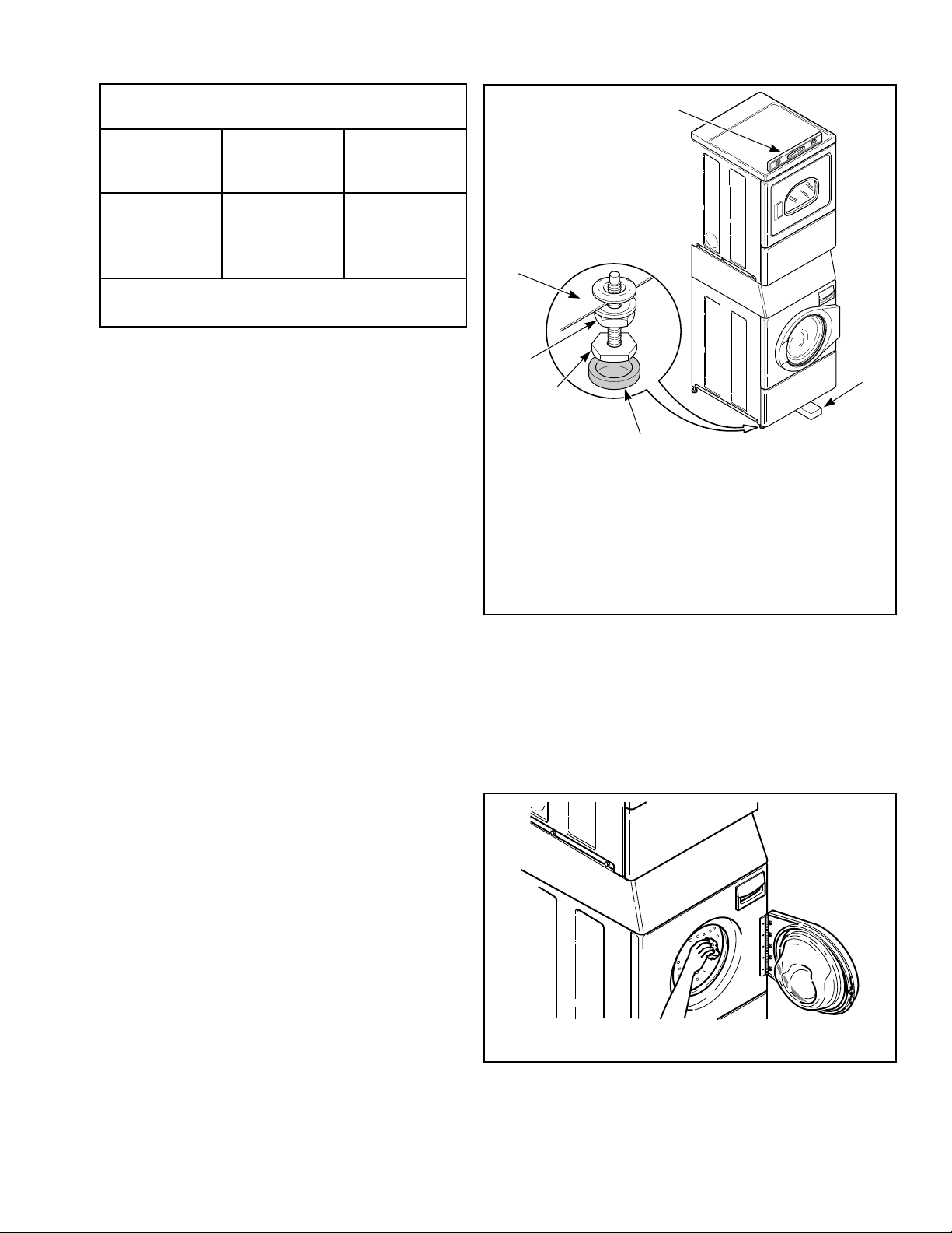
Position and Level the Unit
WARNING
Units elevated above floor level must be anchored to
that elevated surface, base or platform. The material
used to elevate the unit should also be anchored to
the floor to ensure that the unit will not walk or that
the unit can not be physically pulled, tipped or slid
from its installed position. Failure to do so may re-
sult in conditions which can produce serious injury,
death and/or property damage.
W307
1. Position unit so it has sufficient clearance for installation and
servicing.
SWD1006N_SVG
C
E
E
A B
D
NOTE: Shaded areas indicate adjacent structure.
Dryer and Exhaust Duct Clearances
Area Description
Minimum
Clearance
A Left Dryer Side 0 in. [0 mm]
B Right Dryer Side 1 in. [25 mm]
C Dryer Top 6 in. [152 mm]
D * Dryer Rear 4 in. [102 mm]
Table continues...
Installation
©
Copyright, Alliance Laundry Systems LLC -
DO NOT COPY or TRANSMIT
30 Part No. 805420ENR4
Dryer and Exhaust Duct Clearances
Area Description
Minimum
Clearance
E Exhaust Duct
Clearance to
Combustible Ma-
terials
2 in. [51 mm]
* Rear clearance is minimum. 6 inches [152 mm] are
recommended when venting through rear of unit.
NOTE: Use of the dispenser drawer or unit doors as
a handle in the transportation of the unit may cause
damage to the dispenser or doors.
2. Place unit in position on a solid, sturdy and level floor. Instal-
ling the unit on any type of carpeting, soft tile or other weakly
supported structures is not recommended.
3. Place a level on the raised portion of cabinet top and check if
the unit is level from side to side and front to back.
4. If unit is not level, tilt unit to access the front and rear level-
ing legs. For easier access to leveling legs, prop up unit with a
wooden block.
5. Loosen 7/8 in. locknut and adjust legs by screwing into or out
of unit base until the unit is level from side to side and front
to back (using a level). Unit should not rock.
NOTE: Leveling legs can also be adjusted from in-
side the unit using an adjustable wrench.
6. Tighten the locknuts securely against the unit base. If the
locknuts are not tight, unit will move out of position during
operation.
NOTE: DO NOT slide unit across floor if the leveling
legs have been extended. Legs and base could be-
come damaged.
7. Remove rubber feet from accessories bag and place on all
four leveling legs.
8. Verify that unit doesn’t rock.
SWD1029N_SVG
4
5
3
2
6
1
1. Level
2. Wood Block
3. Rubber Foot
4. Leveling Leg
5. Locknut
6. Unit Base
Figure 27
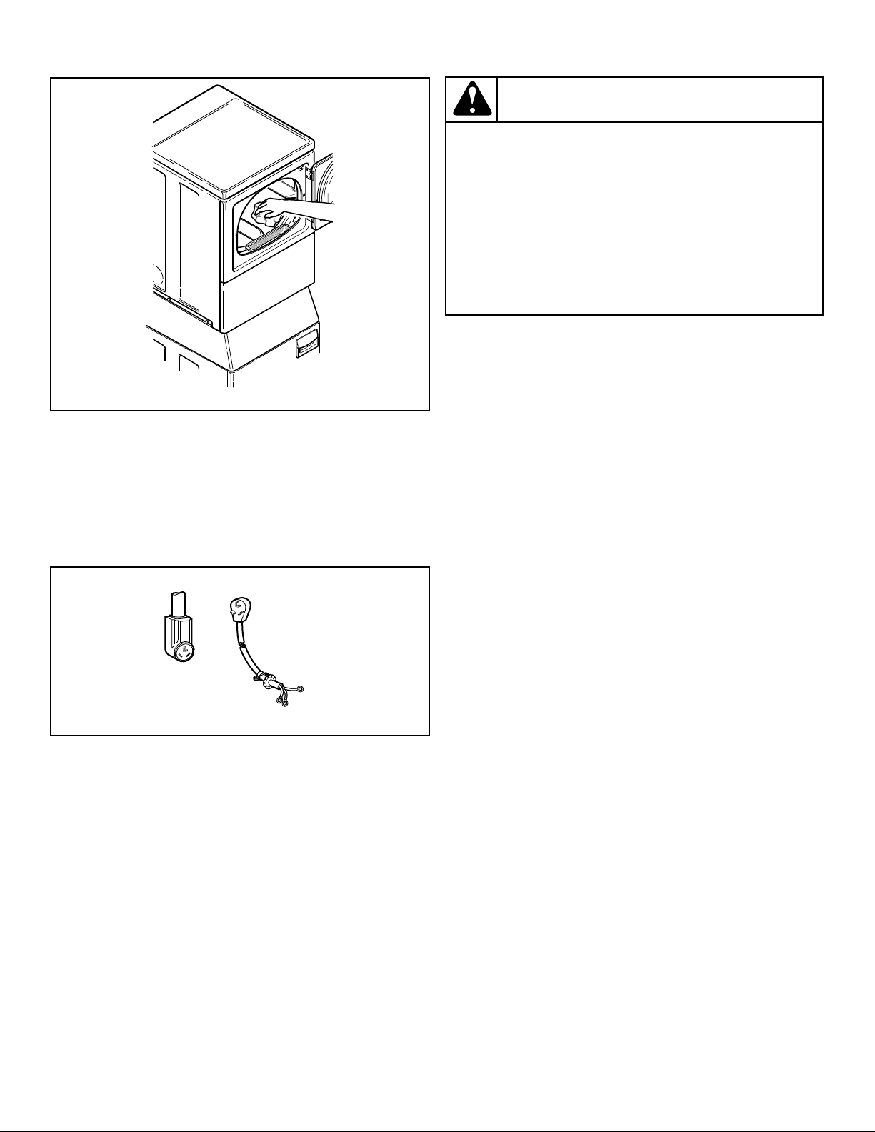
Wipe Out Inside of Washer and Dryer
Drums
IMPORTANT: Prior to first wash, use an all-purpose
cleaner, or a detergent and water solution, and a damp
cloth to remove shipping dust from inside the drums.
SWD1012N_SVG
Figure 28
Installation
©
Copyright, Alliance Laundry Systems LLC -
DO NOT COPY or TRANSMIT
31 Part No. 805420ENR4
SWD1013N_SVG
Figure 29
Plug In the Washer and Dryer
Electric Dryer
Connect the dryer to an electrical power source. Refer to Connect
Electrical Plug section for information on connecting power cord.
Connect to 30 Amp Circuit
D275I_SVG2
Figure 30
Gas Dryer
Dryer requires 120 Volt, 60 Hertz electrical supply and comes
equipped with a 3-prong earth/ground plug. Refer to serial plate
for specific electrical requirements.
NOTE: The wiring diagram is located in the control cab-
inet.
WARNING
To reduce the risk of fire, electric shock, serious in-
jury or death, all wiring and grounding MUST con-
form with the latest edition of the National Electrical
Code, ANSI/NFPA 70, or the Canadian Electrical
Code, CSA C22.1, and such local regulations as
might apply. It is the customer’s responsibility to
have the wiring and fuses installed by a qualified
electrician to make sure adequate electrical power is
available to the dryer.
W521
When plugging in the dryer:
• DO NOT overload circuits.
• DO NOT use an extension cord.
• DO NOT use an adapter.
• DO NOT operate both a washer and a gas dryer on the same
circuit. Use separately fused 15 Amp circuits.
The dryer is designed to be operated on a separate branch, polar-
ized, three-wire, effective earth/ground, 120 Volt, 60 Hertz, AC
(alternating current) circuit protected by a 15 Ampere fuse,
equivalent fusetron or circuit breaker.
The three-prong earth/ground plug on the power cord should be
plugged directly into a polarized three-slot effective earth/ground
receptacle rated 120 Volts AC (alternating current) 15 Amps. Re-
fer to Figure 31 to determine correct polarity of the wall recepta-
cle.
Installation
©
Copyright, Alliance Laundry Systems LLC -
DO NOT COPY or TRANSMIT
32 Part No. 805420ENR4
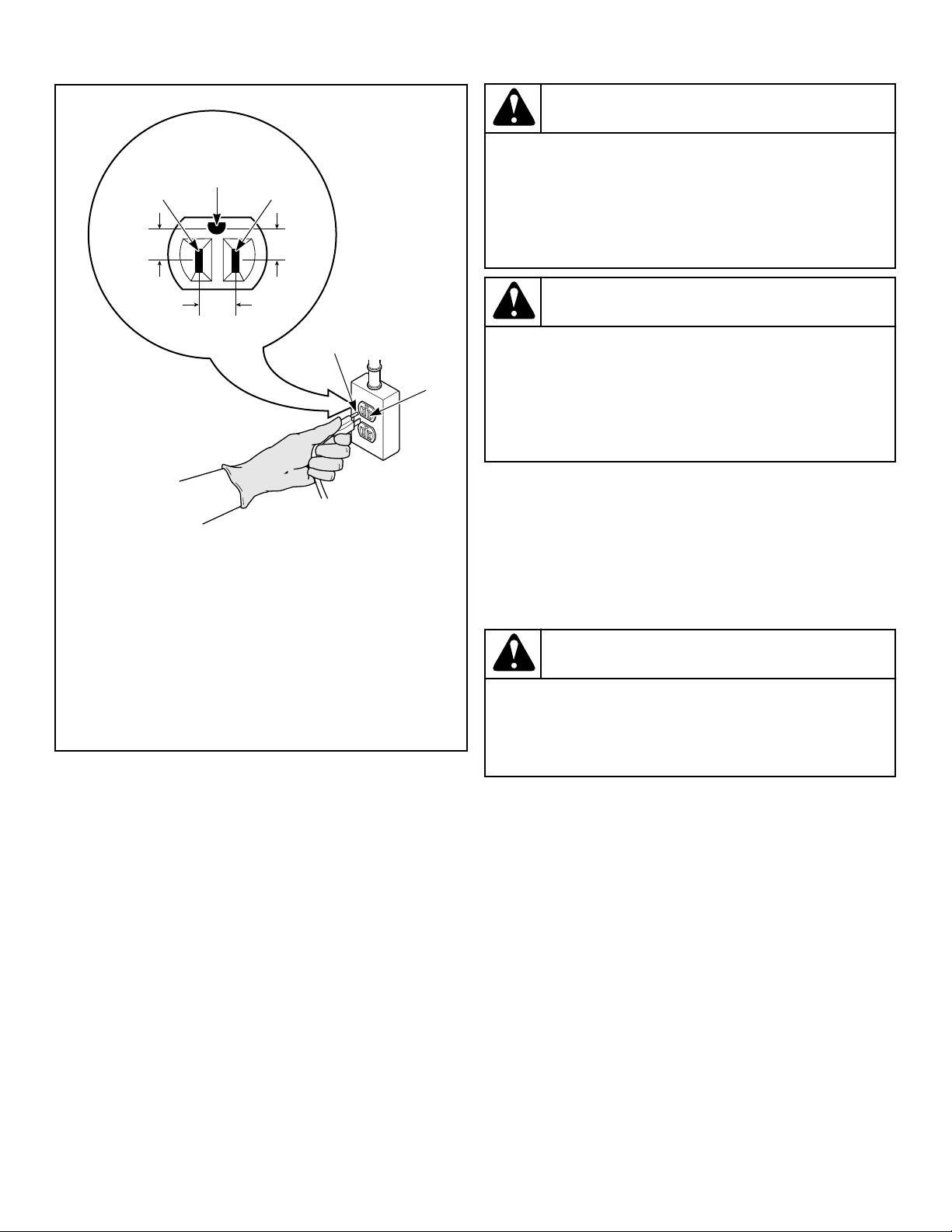
Plug Cord Into Separately Fused 15 Amp Circuit
TLW2287N_SVG
6
8
7
2
1 3
5
4
1. L1
2. Earth/Ground
3. Neutral
4. Round Earth/Ground Plug
5. Neutral Side
6. 0 V.A.C.
7. 120 ± 12 V.A.C.
8. 120 ± 12 V.A.C.
Figure 31
Earth/Ground Information
This appliance must be properly connected to protective earth/
ground. In the event of malfunction or breakdown, the earth/
ground will reduce the risk of electric shock by providing a path
of least resistance for electric current.
The dryer is equipped with a cord having an equipment earth/
ground conductor and a three-prong earth/ground plug. The
three-prong earth/ground plug on the power cord should be plug-
ged directly into a polarized three-slot effective earth/ground re-
ceptacle rated 110/120 Volts AC (alternating current) 15 Amps.
WARNING
This unit is equipped with a three-prong (earth/
ground) plug for your protection against shock haz-
ard and should be plugged directly into a protective
earth/ ground three-prong receptacle. Do not cut or
remove the earth/ground prong from this plug.
W823
WARNING
Improper connection of the equipment earth/ground
conductor can result in a risk of electric shock.
Check with a qualified electrician or service person if
you are in doubt as to whether the dryer is properly
connected to a protective earth/ground.
W886
Do not modify the plug provided with the dryer – if it will not fit
the outlet, have a proper outlet installed by a qualified electrician.
NOTE: Have a qualified electrician check the polarity of
the wall receptacle. If a voltage reading is measured
other than that illustrated, the qualified electrician
should correct the problem.
Do not operate other appliances on the same circuit.
WARNING
To reduce the risk of an electric shock or fire, DO
NOT use an extension cord or an adapter to connect
the dryer to the electrical power source.
W037
Washer
Washer requires 120 Volt, 60 Hertz electrical supply and comes
equipped with a 3-prong earth/ground plug. Refer to serial plate
for specific electrical requirements.
NOTE: The wiring diagram is located behind the con-
trol panel, inside the control cabinet.
Installation
©
Copyright, Alliance Laundry Systems LLC -
DO NOT COPY or TRANSMIT
33 Part No. 805420ENR4
WARNING
To reduce the risk of fire, electric shock, serious in-
jury or death, all wiring and protective earth/ground
connections MUST conform with the latest edition of
the National Electrical Code, ANSI/NFPA No. 70, and
such local regulations as might apply. It is the cus-
tomer’s responsibility to have the wiring, fuses and
circuit breakers installed by a qualified electrician to
make sure adequate electrical power is available to
the washer.
W824
When plugging in the washer:
• DO NOT overload circuits.
• DO NOT use an extension cord.
• DO NOT use an adapter.
• DO NOT operate both a washer and a gas dryer on the same
circuit. Use separately fused 15 Amp circuits.
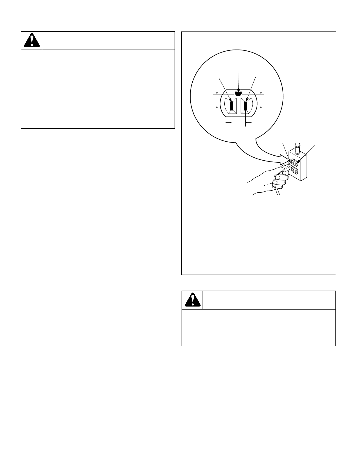
The washer is designed to be operated on a separate branch, po-
larized, three-wire, effective earth/ground, 120 Volt, 60 Hertz,
AC (alternating current), circuit protected by a 15 ampere fuse,
equivalent fusetron or circuit breaker.
The three-prong earth/ground plug on the power cord should be
plugged directly into a polarized three-slot effective earth/ground
receptacle rated 110/120 Volts AC (alternating current) 15 Amps.
Refer to Figure 32 to determine correct polarity of the wall recep-
tacle.
Standard 120 Volt, 60 Hertz 3-Wire Effective Earth/
Ground Circuit
DRY2022N_SVG
7
6
8
5
4
3
2
1
1. L1
2. Earth/Ground
3. Neutral Side
4. Round Earth/Ground Prong
5. Neutral
6. 0 V.A.C.
7. 120 ± 12 V.A.C.
8. 120 ± 12 V.A.C.
Figure 32
WARNING
To reduce the risk of an electric shock or fire, DO
NOT use an extension cord or an adapter to connect
the washer to the electric power source.
W082
Earth/Ground Instructions
This appliance must be properly connected to protective earth/
ground. In the event of malfunction or breakdown, the earth/
ground will reduce the risk of electric shock by providing a path
of least resistance for electric current.
The appliance is equipped with a cord having an equipment earth/
ground conductor and a three-prong earth/ground plug. The plug
must be plugged into an appropriate outlet that is properly instal-
led and connected to a protective earth/ground in accordance with
all local codes and ordinances.
Installation
©
Copyright, Alliance Laundry Systems LLC -
DO NOT COPY or TRANSMIT
34 Part No. 805420ENR4
WARNING
Improper connection of the equipment earth/ground
conductor can result in a risk of electric shock.
Check with a qualified electrician or service person if
you are in doubt as to whether the unit is properly
connected to a protective earth/ground.
W893
• DO NOT modify the plug provided with the unit – if it will
not fit the outlet, have a proper outlet installed by a qualified
electrician.
• If the laundry room’s electrical supply does not meet the
above specifications and/or if you are not sure the laundry
room has an effective earth/ground, have a qualified electri-
cian or your local electrical utility company check it and cor-
rect any problems.
• Do not operate other appliances on the same circuit when this
appliance is operating.
WARNING
Any disassembly requiring the use of tools must be
performed by a suitably qualified service person.
W299
WARNING
This unit is equipped with a three-prong (earth/
ground) plug for your protection against shock haz-
ard and should be plugged directly into a protective
earth/ ground three-prong receptacle. Do not cut or
remove the earth/ground prong from this plug.
W823
Check Installation
1. Refer to Installer Checklist on the back cover of this manual
and make sure that unit is installed correctly.
2. Run washer with a test load to make sure it is operating prop-
erly and properly leveled.
a. Put about six pounds of laundry (four bath towels and
three jeans) into washer.
b. Close door.
c. Rapid advance to the final spin part of the cycle.
d. When washer spins at high speed, verify that it is stable.
e. If it is not, after cycle is complete, refer to Position and
Level the Washer to readjust leveling legs.
Check Heat Source
Electric Dryers
1. Close the loading door and start the dryer in a heat setting (re-
fer to the operation instructions).
2. After the dryer has operated for three minutes, the exhaust air
or exhaust pipe should be warm.
Gas Dryers
IMPORTANT: This operation is to be conducted by
qualified personnel only.
1. To view the burner flame, remove the lower front panel of the
dryer.
2. Close the loading door and start the dryer in a heat setting (re-
fer to the operation instructions). The dryer will start, the ig-
niter will glow red and the main burner will ignite.
IMPORTANT: If all air is not purged out of gas line,
gas igniter may go off before gas is ignited. If this
happens, after approximately two minutes igniter
will again attempt gas ignition.
IMPORTANT: If igniter does not light, make sure gas
is turned on.
3. After the dryer has operated for approximately five minutes,
observe burner flame through lower front panel.
4. Adjust the air shutter to obtain a soft, uniform blue flame. (A
lazy, yellow-tipped flame indicates lack of air. A harsh, roar-
ing, very blue flame indicates too much air.) Adjust the air
shutter as follows:
a. Loosen the air shutter lockscrew.
b. Turn the air shutter to the left to get a luminous yellow-
tipped flame, then turn it back slowly to the right to obtain
a steady, soft blue flame.
c. After the air shutter is adjusted for proper flame, tighten
the air shutter lockscrew securely.
5. Reinstall the lower front panel.
WARNING
To reduce the risk of serious injury or death, low-
er front panel must be in place during normal op-
eration.
W158
6. After the dryer has operated for approximately three minutes,
exhaust air or exhaust pipe should be warm.
Installation
©
Copyright, Alliance Laundry Systems LLC -
DO NOT COPY or TRANSMIT
35 Part No. 805420ENR4
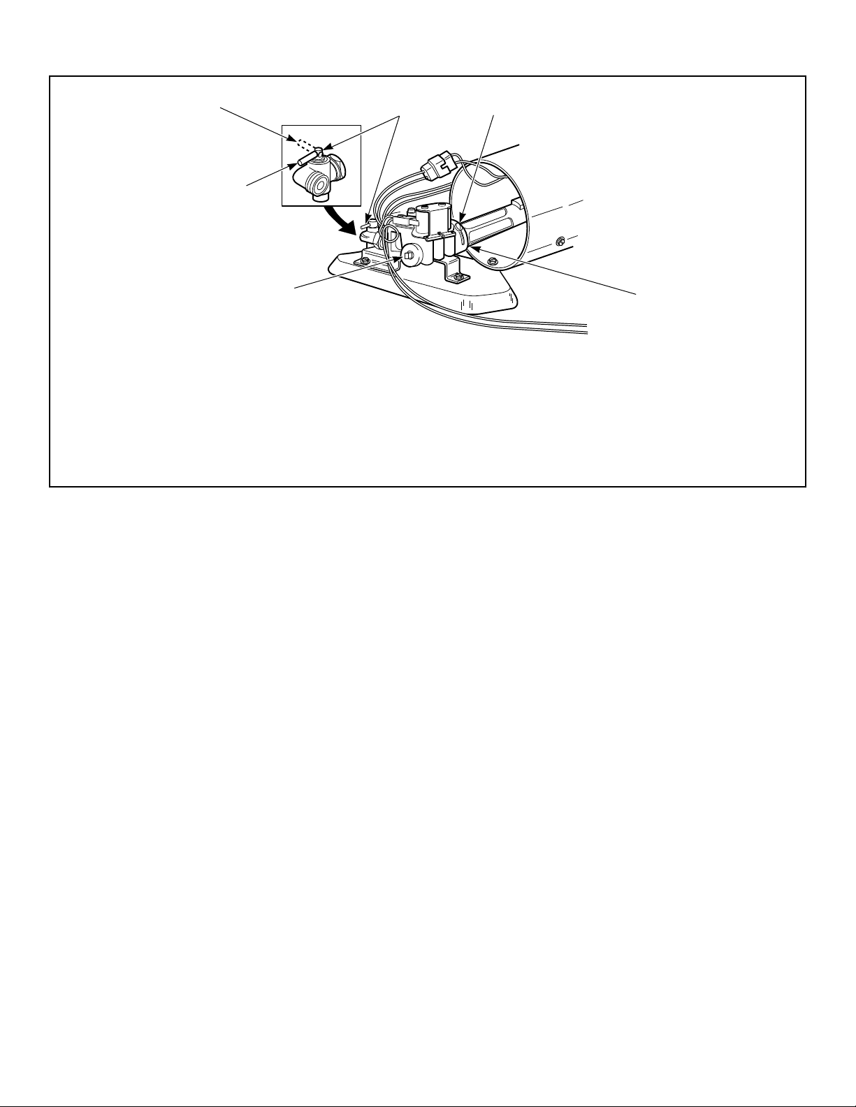
Shut-off Valve Only Applicable on Certain Models
DRY2753N_SVG
3
1
6
5
4
2
1. Air Shutter Lockscrew
2. Air Shutter
3. 1/8 in. [3.1 mm] Pipe Plug (For checking manifold pressure)
4. Shut-off Valve Open Position
5. Shut-off Valve Closed Position
6. Shut-off Valve Handle
Figure 33
Installation
©
Copyright, Alliance Laundry Systems LLC -
DO NOT COPY or TRANSMIT
36 Part No. 805420ENR4
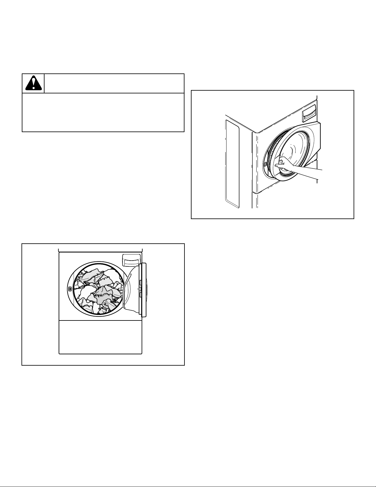
Operation
Operation Instructions for Washers
WARNING
To reduce the risk of fire, electric shock, or injury to
persons, read the IMPORTANT SAFETY INSTRUC-
TIONS before operating this appliance.
W727
IMPORTANT: Prior to first wash, use an all-purpose
cleaner, or a detergent and water solution, and a damp
cloth to remove shipping dust from inside of washer.
IMPORTANT: Remove all sharp objects from laundry to
avoid tears and rips to items during normal machine
operation.
Load Laundry
1. Load items loosely into wash drum. (21 pounds [9.5 kg] max-
imum dry clothes load)
NOTE: Small items such as baby socks may get
caught around the door. Place these articles inside
a mesh garment bag.
FLW2309N_SVG
Figure 34
2. When washing bulky items such as blankets and comforters,
use the DELICATES/BULKY cycle. The cycle includes agi-
tation and final spin speeds that maintain the load’s balance
and minimize wear to the articles.
NOTE: Different fabrics will have different densities
and loads must be adjusted accordingly to meet ma-
chine loading specifications shown.
Close Loading Door
Close loading door tightly. The washer will not operate with
the loading door open.
FLW2310N_SVG
Figure 35
Add Laundry Supplies
1. Open dispenser drawer.
2. Measure and add low sudsing, high efficiency (HE) main
wash detergent (1), bleach (2), fabric softener (3) and pre-
wash detergent (4) to the dispenser drawer.
IMPORTANT: If using single-load laundry detergent
packets or 3-in-1 laundry sheets, DO NOT place
them in the dispenser drawer. Place them directly in
the wash drum with clothes.
IMPORTANT: If using non-HE detergent, avoid over-
sudsing by using 1/2 of the detergent manufactur-
er’s recommended amount.
3. Close dispenser drawer.
Operation
©
Copyright, Alliance Laundry Systems LLC -
DO NOT COPY or TRANSMIT
37 Part No. 805420ENR4
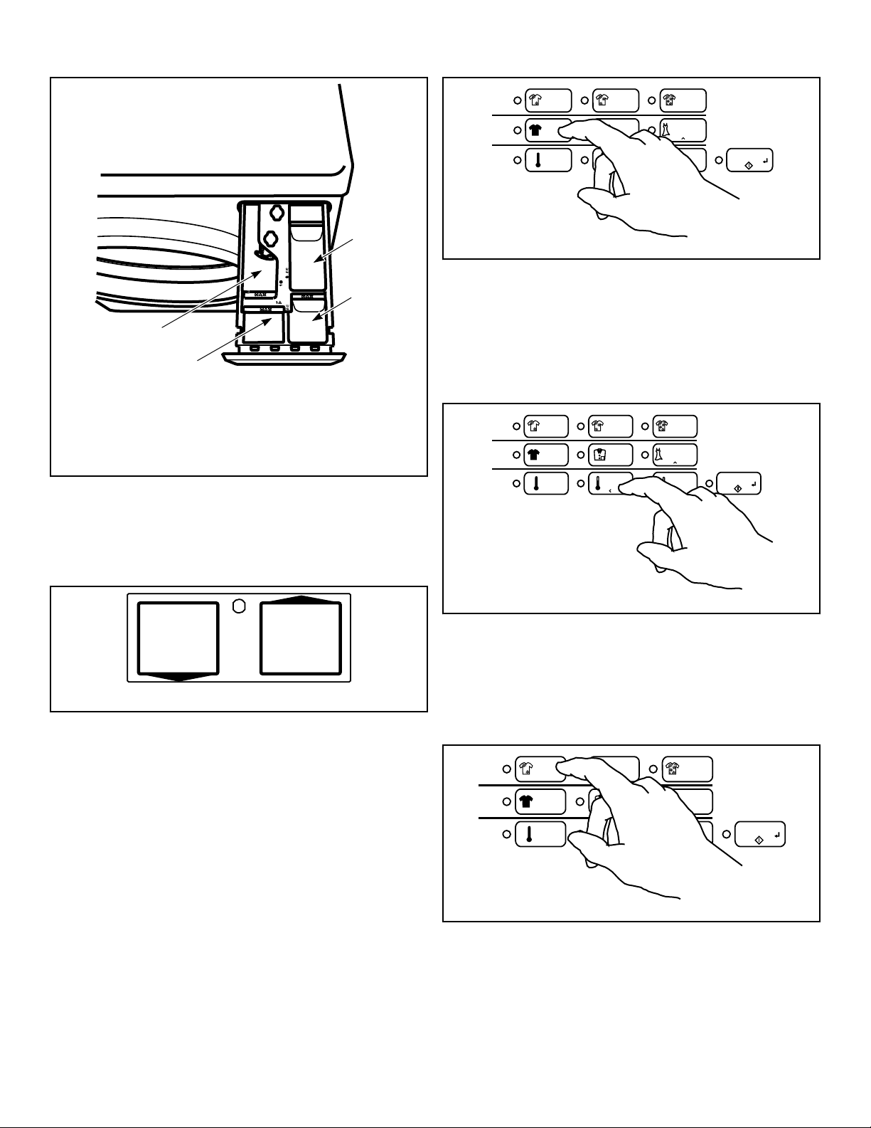
FLW2389N_SVG
E
H
H
R
S
P
O
R
F
E
T
W
W
E
A
A
N
N
A
M
I
S
S
LIQUID BLEACH
3
2
1
4
1. Main Wash Detergent
2. Liquid Bleach
3. Fabric Softener
4. Pre-Wash Detergent
Figure 36
Determine Proper Controls
The direction of the arrow indicates which control is for which
unit.
SWD960N_SVG
Figure 37
Set Cycle
1. Push touchpad for NORMAL, PERM PRESS or DELI-
CATES/BULKY cycle.
2. Light indicates selection.
NOTE: Changes can be made to Fabric Selector setting
up until the first fill is complete.
FLW2341N_SVG
Soil
Cycle
Temp
MEDIUM
LIGHT
NORMAL
HOT WARM COLD
HEAVY
PERM
PRESS
DELICATES/
BULKY
START
Figure 38
Set Wash Temperature
1. Push touchpad for HOT, WARM or COLD.
2. Light indicates selection.
NOTE: Always follow manufacturer's care labels.
FLW2342N_SVG
Soil
Cycle
Temp
MEDIUM
LIGHT
NORMAL
HOT WARM COLD
HEAVY
PERM
PRESS
DELICATES/
BULKY
START
Figure 39
Set Soil Level
1. Push Soil Level touchpad to select LIGHT, MEDIUM or
HEAVY.
2. LED light indicates selection.
FLW2343N_SVG
Soil
Cycle
Temp
MEDIUM
LIGHT
NORMAL
HOT WARM COLD
HEAVY
PERM
PRESS
DELICATES/
BULKY
START
Figure 40
Insert Coins or Card
To Insert Coins
1. Insert coin(s) in coin slot.
Operation
©
Copyright, Alliance Laundry Systems LLC -
DO NOT COPY or TRANSMIT
38 Part No. 805420ENR4
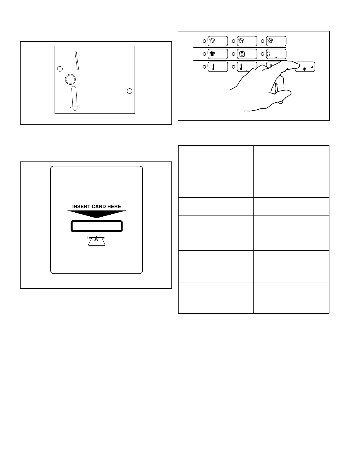
2. Check pricing as seen on digital display.
W387I_SVG
Figure 41
To Insert Card
Insert card into opening.
DRY2633N_SVG
Figure 42
Start Washer
1. After vend price has been satisfied, push the START pad.
2. Door must be closed to start washer.
FLW2344N_SVG
Soil
Cycle
Temp
MEDIUM
LIGHT
NORMAL
HOT WARM COLD
HEAVY
PERM
PRESS
DELICATES/
BULKY
START
Figure 43
Indicator Lights
INSERT COINS/CARD INSERT COINS/CARD is lit
to prompt the user to insert
coins or card to satisfy the
vend price. When INSERT
COINS/CARD is lit, the digits
show the vend price remaining
to be satisfied.
WASH WASH is lit during the WASH
portions of the cycle.
RINSE RINSE is lit during the RINSE
portions of the cycle.
SPIN SPIN is lit during the final spin
portion of the cycle.
DOOR DOOR is lit whenever the
door is locked. The door can-
not be opened when this light
is on.
START START flashes one second on
and one second off when the
full vend price has been satis-
fied.
IMPORTANT: If washer fails to operate properly after
installation, make sure electrical service and water
supply faucets are turned on. Are all the controls prop-
erly set? Have a qualified service person refer to the
wiring diagram (located inside of washer control cabi-
net) and check for broken, loose or incorrect wiring.
NOTE: Once a cycle has started, the door can only be
opened by first unplugging the power cord and waiting
one minute.
Operation
©
Copyright, Alliance Laundry Systems LLC -
DO NOT COPY or TRANSMIT
39 Part No. 805420ENR4
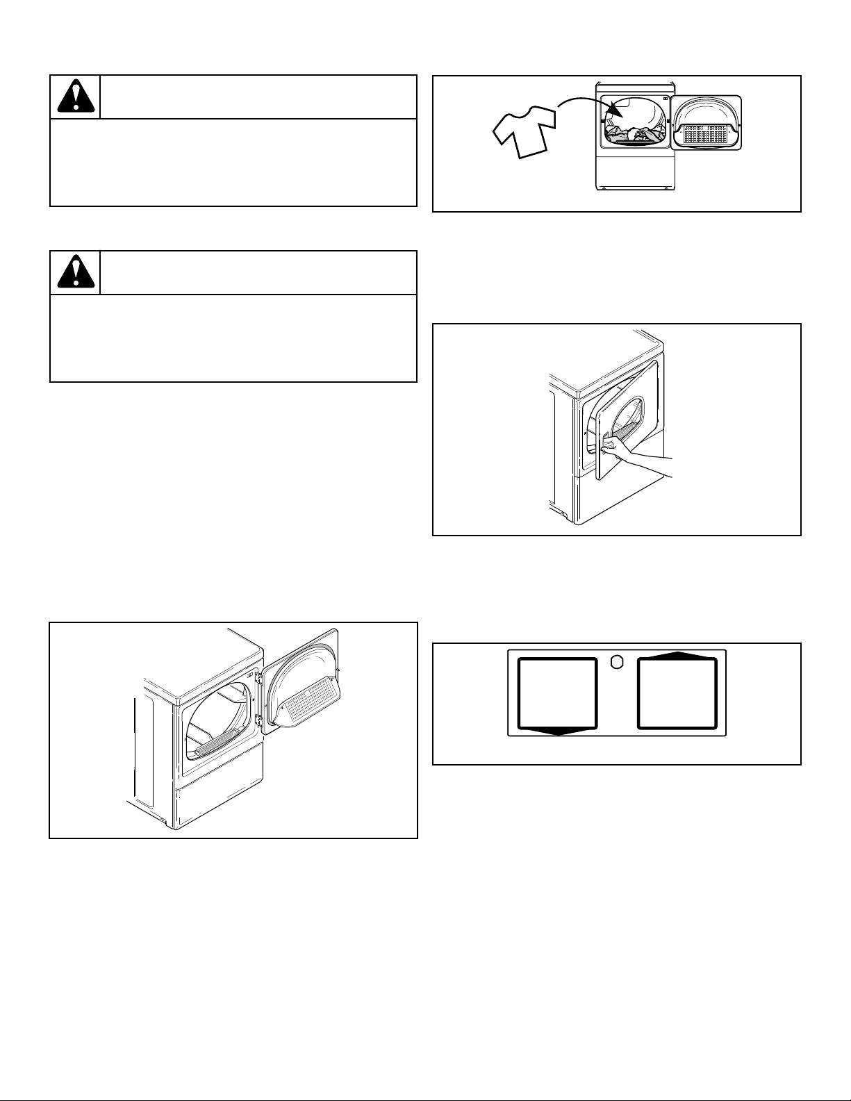
WARNING
To reduce the risk of bodily injury, do not remove
laundry from washer until all lights are out, and all
moving parts have stopped.
W092
Operation Instructions for Dryers
WARNING
To reduce the risk of fire, electric shock, or injury to
persons, read the IMPORTANT SAFETY INSTRUC-
TIONS before operating this appliance.
W727
IMPORTANT: Before using dryer for the first time, use
an all-purpose cleaner, or a detergent and water solu-
tion, and a damp cloth to remove shipping dust from
inside of dryer drum.
IMPORTANT: Remove all sharp objects from laundry to
avoid tears and rips to items during normal machine
operation.
IMPORTANT: Remove all objects from pockets such as
lighters and matches.
Clean Lint Filter
Clean lint filter before each use.
D608I_SVG
Figure 44
Load Laundry
1. Load clothes loosely into dryer drum (18.0 lbs. [8.2 Kg] max-
imum dry clothes load).
2. Add fabric softener sheet if desired.
IMPORTANT: To avoid damage to dryer, do not use
more than one fabric softener sheet per load.
D717I_SVG
Figure 45
Close Loading Door
1. Close loading door.
2. Dryer will not operate with the door open.
SWD1032N_SVG
Figure 46
Determine Proper Controls
The direction of the arrow indicates which control is for which
unit.
SWD960N_SVG
Figure 47
Set Fabric Selector
Select HIGH TEMP, MED TEMP, LOW TEMP, DELICATES or
NO HEAT by pushing touchpad.
NOTE: Always follow manufacturer's care labels.
Operation
©
Copyright, Alliance Laundry Systems LLC -
DO NOT COPY or TRANSMIT
40 Part No. 805420ENR4
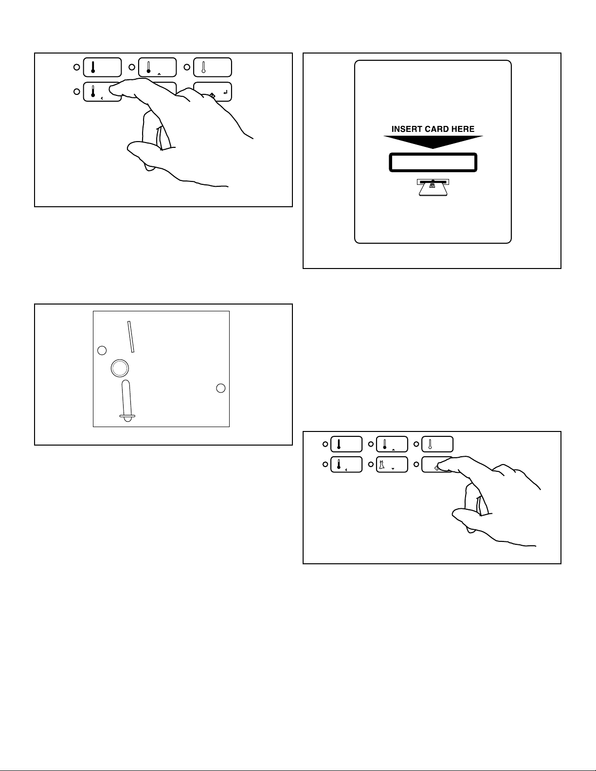
DRY2534N_SVG
DELICATES
START
MED
TEMP
HIGH
TEMP
LOW
TEMP
NO
HEAT
Figure 48
Insert Coins or Card
To Insert Coins
1. Insert coin(s) in coin slot.
2. Check pricing as seen on digital display.
W387I_SVG
Figure 49
To Insert Card
Insert card into opening.
DRY2633N_SVG
Figure 50
Start Dryer
1. To start dryer, push START pad.
2. To stop dryer at any time, open the door.
3. To restart the dryer, close door and push START pad. Cycle is
completed when time remaining reaches 00 minutes.
If Additional Time Feature is turned on, additional dryer time
may be purchased at cycle start or while dryer is running.
Remove knits when slightly damp because overdrying may cause
shrinkage. Do not tumble dry knit woolens.
DRY2535N_SVG
DELICATES
START
MED
TEMP
HIGH
TEMP
LOW
TEMP
NO
HEAT
Figure 51
IMPORTANT: The final part of dryer cycle occurs with-
out heat (cool down cycle) to ensure that items in dryer
are left at a temperature that ensures that the items will
not be damaged.
Operation
©
Copyright, Alliance Laundry Systems LLC -
DO NOT COPY or TRANSMIT
41 Part No. 805420ENR4

WARNING
To prevent the risk of fire, never stop a dryer before
the end of the drying cycle unless all items are
quickly removed and spread out so that the heat is
dissipated.
W756
NOTE: This machine includes an extended tumble fea-
ture. Starting 20 minutes after a cycle ends, the cylin-
der will tumble for two minutes every hour without
heat, up to 18 hours or until door is opened.
Indicator Lights
INSERT COINS/CARD INSERT COINS/CARD is lit
to prompt the user to insert
coins or a card to satisfy the
vend price. When INSERT
COINS/CARD is lit,the three
digits will display the vend
price remaining to be satisfied.
START START is lit whenever the
dryer is not in a cycle, the full
vend price has been satisfied
and the dryer door is closed.
When the START pad is press-
ed, the cycle will begin or re-
sume.
DRYING DRYING is lit to indicate that
one of the heated cycles
(HIGH TEMP, MED TEMP,
LOW TEMP or DELICATES)
is currently in operation. DRY-
ING will turn off at the end of
a heated cycle or when the
COOL DOWN cycle begins.
COOL DOWN COOL DOWN is lit whenever
the COOL DOWN portion of a
heated cycle is active. It is also
lit when the NO HEAT cycle is
in operation.
Operation
©
Copyright, Alliance Laundry Systems LLC -
DO NOT COPY or TRANSMIT
42 Part No. 805420ENR4

Maintenance
User-Maintenance Instructions
Lubrication
All moving parts are sealed in a permanent supply of lubricant or
are equipped with oilless bearings. Additional lubrication will not
be necessary.
Cold Weather Care
If the unit is delivered on a cold day (below freezing), or is stored
in an unheated room or area during the cold months, do not at-
tempt to operate the washer until it has had a chance to warm up.
Water from the previous cycle may remain.
Extended Non-Use
IMPORTANT: To avoid possible property damage due
to flooding, turn off the water supply to the washer
whenever there will be an extended period of non-use.
Leave the loading door and dispenser drawer open during extend-
ed periods of non-use to allow the wash drum and drawer to dry
out and avoid a musty smell.
Care of Your Washer
Use only a damp or sudsy cloth for cleaning the control panel.
Some cleaning products may harm the finish on the control panel
or damage the interior. DO NOT use products that contain alco-
hol on the control panel. Wipe the panel dry after cleaning.
Wipe the washer cabinet as needed. If detergent, bleach or other
washing products are spilled on the cabinet, wipe immediately.
Some products will cause permanent damage if spilled on the
cabinet.
Do not use scouring pads or abrasive cleansers on control panel
or cabinet.
The wash drum will need no particular care although it may need
rinsing or wiping after an unusual load has been washed.
The outside of the door window can be cleaned with household
window cleaner.
Leave the door and dispenser drawer open slightly when not in
use. This will help keep them dry and prevent musty smells.
Running an occasional rinse cycle with bleach will help to avoid
a musty smell in the wash drum.
Cleaning Glass Sealing Area
In order to assure that the door properly seals against water leaks,
the following surfaces should be wiped off periodically:
• The outside perimeter of the door glass where the seal con-
tacts the glass
• The front surface of the door seal lip
Usually a mild soap solution will work. If there is an extreme
build-up of minerals from a hard water supply, the surfaces may
need to be cleaned with a lime removal chemical.
Replacing Hoses
Hoses and other rubber parts deteriorate after extended use. Ho-
ses may develop cracks, blisters or material wear from the tem-
perature and constant high pressure they are subjected to.
All hoses should be checked on a monthly basis for any visible
signs of deterioration. Any hose showing the signs of deteriora-
tion listed above should be replaced immediately. All hoses
should be replaced every five years.
Filter Screens
Check the filter screens in the fill hoses for debris or damage ev-
ery six months. Clean or replace them if necessary.
If the washer is filling with water slower than normal, check the
filter screens. Clean or replace them if necessary.
Order filter screen Part No. 803615 from the nearest authorized
parts distributor.
Cleaning Foreign Object Trap
The washer’s pump has a trap that may collect foreign objects.
The trap may need to be cleaned if water is draining slower than
usual. To clean:
1. Disconnect washer from electrical supply.
2. Remove two screws at bottom of the front access panel.
3. Rotate bottom of panel out and remove panel.
NOTE: The pump may have some water in it. Use a
rag or a container to catch water. If the wash drum
is full of water, use a wet/dry shop vacuum to catch
the water.
4. With rag or vacuum ready, unscrew the cap on the left side of
the pump and remove trap.
5. Clean the debris from the trap.
6. Reinstall the trap and access panel.
7. Reconnect washer to electrical supply.
Care of Your Dryer
WARNING
To reduce the risk of an electric shock, serious injury
or death, disconnect the electrical service to the dry-
er before cleaning the interior.
W132
Maintenance
©
Copyright, Alliance Laundry Systems LLC -
DO NOT COPY or TRANSMIT
43 Part No. 805420ENR4
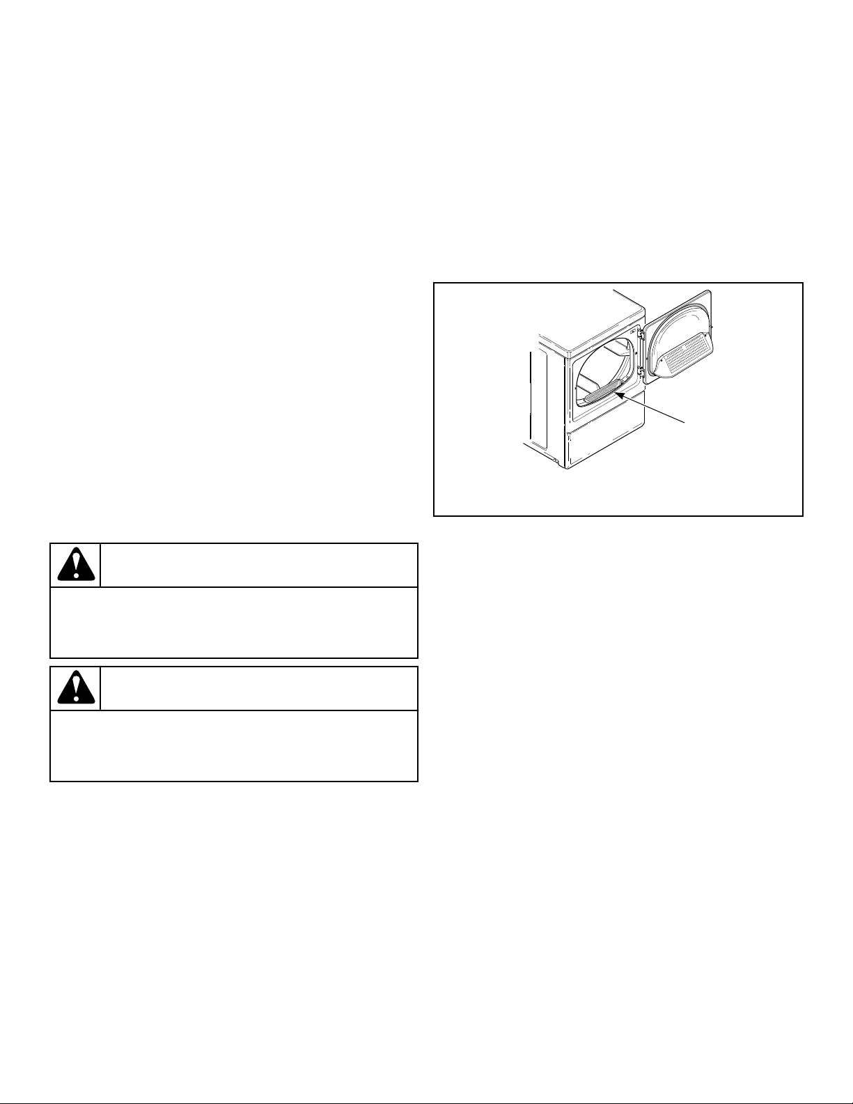
Dryer Interior
Wipe the surfaces using a soft cloth and household cleaner or a
non-abrasive paste of powdered laundry detergent and hot water,
followed by a short heat cycle with a load of rags.
To remove crayon or ball point ink off the dryer drum, put the
heat on high and use old rags in the dryer to absorb the crayon or
ink. If unsuccessful, contact the appliance dealer. DO NOT use
any chemicals in the dryer.
IMPORTANT: The use of chlorine bleach for removing
any discolorations should be avoided because bleach
could damage the finish.
Cabinet
Wipe the dryer cabinet as needed. If detergent, bleach or other
washing products have been spilled on the dryer, wipe immedi-
ately. Some products will cause permanent damage if spilled on
the cabinet.
Control Panel
Use only a damp or sudsy cloth for cleaning the control panel.
Some spray pretreat products may harm the finish on the control
panel. DO NOT use products that contain alcohol on the control
panel.
Exhaust System
WARNING
To reduce the risk of electric shock, disconnect the
electrical service to the dryer before cleaning.
W043
WARNING
Any disassembly requiring the use of tools must be
performed by a suitably qualified service person.
W299
The exhaust duct should be inspected after one year of use and
cleaned if necessary by a qualified service person to remove any
lint build-up. Inspect and clean exhaust duct every one to two
years as required thereafter.
NOTE: This recommended maintenance is not covered
under the terms of the warranty.
The weather hood should be checked frequently to make sure the
dampers move freely, dampers are not pushed in and that nothing
has been set against them.
Keep dryer area clear and free from combustible materials, gaso-
line and other flammable vapors and liquids.
Do not obstruct the flow of combustion and ventilation air.
NOTE: Verify proper operation after servicing.
Lint Filter
CLEAN THE LINT FILTER BEFORE DRYING EACH LOAD.
(Refer to Figure 52 for lint filter location.) Cleaning the lint filter
is important because a layer or pad of lint on the filter will block
the flow of air through the dryer, thus reducing the efficiency of
the dryer. The clothes will take longer to dry and energy will be
wasted.
The lint filter may be washed if needed. Annually remove lint fil-
ter and screw to vacuum the duct under it.
D608I_SVG1
1
1. Lint Filter
Figure 52
Reinstallation of Shipping Materials
To prevent damage while moving the unit, the shipping materials
MUST be reinstalled.
1. Disconnect washer from electrical supply.
2. Remove two screws at bottom of front access panel.
3. Rotate bottom of panel out and remove panel.
4. Attach shipping brace to weight and base using four bolts and
washers. Refer to Figure 53 .
5. Reinstall front access panel.
6. Go to rear of washer to install rear shipping bolt, washer,
spacer assemblies.
7. Insert shipping bolt assemblies into each shipping bolt hole.
Refer to Figure 54 .
8. Tighten bolt while pressing washer against rear panel to en-
sure spacer is fully inserted.
Maintenance
©
Copyright, Alliance Laundry Systems LLC -
DO NOT COPY or TRANSMIT
44 Part No. 805420ENR4
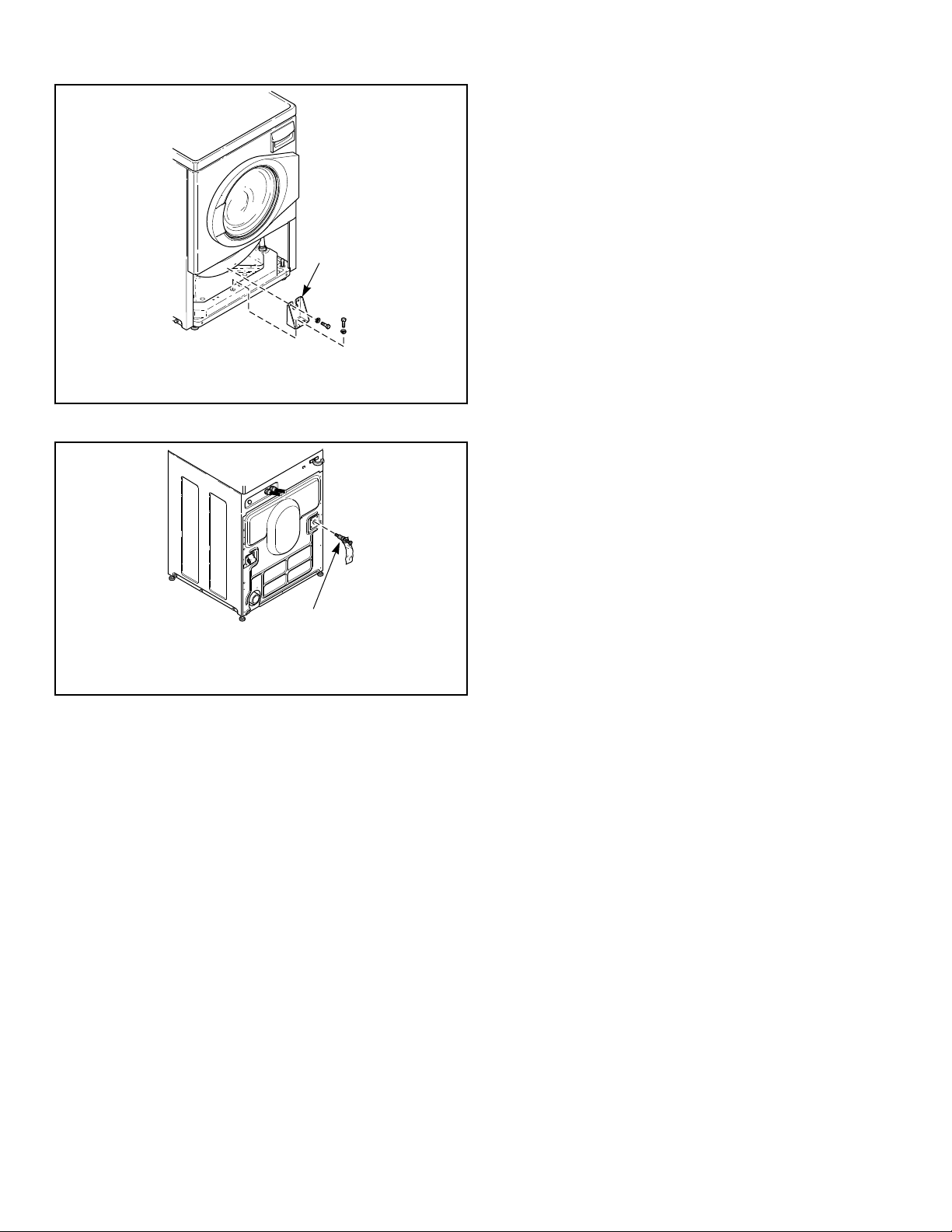
FLW2296N_SVG
1
1. Shipping Brace
Figure 53
FLW2297N_SVG
1
1. Shipping Bolt Assembly
Figure 54
Motor Overload Protector
The dryer’s motor overload protector stops the motor automati-
cally in the event of an overload. After cooling, the overload pro-
tector will reset itself. Dryer can be restarted by pressing the
START pad. If overload protector cycles again, remove the dryer
from use and call the service person to correct the problem.
For Energy Conservation
• Make sure the lint filter is always clean.
• Do not overload dryer.
• Do not overdry clothes.
• Remove items to be ironed while still damp.
• Large loads of similar fabrics dry the most efficiently. How-
ever, dry permanent press in smaller loads to prevent wrin-
kling.
• Use the correct temperature FABRIC SELECTOR setting for
the type of fabric being dried.
• Locate your dryer so the exhaust duct is as short and straight
as possible.
• Do not open the door during the drying cycle.
• Plan to do your laundry on low humidity days; your clothes
will dry faster.
• Should you plan to dry several loads, do them one after anoth-
er, then you do not have to reheat the dryer unit’s interior
parts each time.
Maintenance
©
Copyright, Alliance Laundry Systems LLC -
DO NOT COPY or TRANSMIT
45 Part No. 805420ENR4

Troubleshooting
Try these troubleshooting tips before making a service call. They
may save you time and money.
Washer Symptom Possible Cause/Solution
Won’t Fill • Make sure power cord is plugged all the way into the electrical outlet.
• Check the laundry room fuse or circuit breaker.
• Make sure that the controls are properly set.
• Press START keypad.
• Make sure that the loading door is closed tightly.
• Make sure hot and cold water faucets are turned on.
• Make sure that the fill hoses are not kinked or twisted.
• Clean the screens in the water mixing valve and the filter screens located at the faucet
end of the fill hoses.
Won’t Start • Make sure power cord is plugged all the way into the electrical outlet.
• Check the laundry room fuse or circuit breaker.
• Make sure that the controls are properly set.
• Press START keypad.
• Make sure that the loading door is closed tightly.
• Insert coin(s) or card.
• Make sure door latch is properly adjusted relative to door lock.
Won’t Spin/Tumble • Make sure power cord is plugged all the way into the electrical outlet.
• Check the laundry room fuse or circuit breaker.
• Make sure that the controls are properly set.
• Press START keypad.
• Make sure that the loading door is closed tightly.
• Broken drive belt. Call the service person.
• Foreign object trap in pump may be clogged. Clean the trap. Refer to Maintenance
section.
Stops/Pauses During Cycle • Pauses are part of the washer’s normal operation.
• Check the laundry room fuse or circuit breaker.
• Wash load may be unbalanced. Washer will stop and then restart spin automatically.
Won’t Drain • Make sure drain hose is not kinked or twisted.
• Make sure drain hose is not clogged.
• Make sure drain receptacle is not clogged.
• Refer to the Installation instructions to make sure that the drain hose has been proper-
ly installed.
• Foreign object trap in pump may be clogged. Clean the trap. Refer to Maintenance
section.
Table continues...
Troubleshooting
©
Copyright, Alliance Laundry Systems LLC -
DO NOT COPY or TRANSMIT
46 Part No. 805420ENR4

Washer Symptom Possible Cause/Solution
Water Leaks • Check that fill hoses are properly installed on the faucets and the washer’s water mix-
ing valve.
• Check the condition of the fill hoses. Replace fill hoses every five years.
• Make sure drain receptacle is not clogged.
• Check laundry room plumbing.
• Check the condition of the rubber door gasket for tears or holes.
• Laundry load may be oversudsing. Make sure you are using low-sudsing, high effi-
ciency (HE) detergent.
• Laundry load may be overloaded. Make sure you are using proper load sizes.
• Make sure outside perimeter of the door glass where seal contacts glass is clean.
Too Many Soap Suds • Laundry load may be oversudsing. Make sure you are using low-sudsing, high effi-
ciency (HE) detergent.
• Make sure you are using the amount of detergent recommended on the detergent’s la-
bel. If using non-HE detergent, use only 1/2 of the detergent manufacturer's recom-
mended amount.
• Laundry load may be overloaded. Make sure you are using proper load sizes.
Vibrates/Moves Slightly • Make sure washer is level. Uneven leveling can cause vibration.
• Make sure washer is installed on a solid, sturdy and level floor. The washer should not
be installed on carpeting, soft tile, a platform or other weakly supported structures.
• Make sure rubber feet are installed on all four leveling legs. Refer to Position and
Level the washer.
Is Noisy • Make sure washer is level. Uneven leveling can cause vibration.
• Some sounds may be a part of normal operation for a frontload washer, such as click-
ing noise when door locks and clicking noise from balance ring during agitate part of
cycle.
Load is too Wet • Wash load may be unbalanced. The washer may have limited the spin speed to pre-
vent damage to the machine. Redistribute the load.
• Load is too small. Add items to make full load.
Wrong Water Temperature • Make sure that the controls are properly set.
• Check fill hoses. Make sure hot faucet hose is connected to hot mixing valve (indicat-
ed with “H” on the valve bracket) and cold faucet is connected to cold mixing valve
(indicated with “C” on the valve bracket).
• Make sure laundry room water heater is adjusted properly.
Troubleshooting
©
Copyright, Alliance Laundry Systems LLC -
DO NOT COPY or TRANSMIT
47 Part No. 805420ENR4

Dryer Symptom Possible Cause/Solution
Dryer won’t start • Insert coin(s) or card, if required.
• For dryers equipped with a power cord, make sure the power
cord is plugged all the way into the electrical outlet.
• Make sure loading door is closed.
• Press START pad.
• Make sure the laundry room fuse(s) isn’t blown or loose, or
circuit breakers aren’t open.
• The dryer itself does not have an electrical fuse. An electric
dryer has an electrical circuit with two fuses.
• Check if motor overload protector has cycled. Wait 10 mi-
nutes and try again.
Dryer won’t heat • Make sure the laundry room fuse(s) isn’t blown or loose, or
circuit breakers aren’t open.
• The dryer itself does not have an electrical fuse. An electric
dryer has an electrical circuit with two fuses.
• Make sure controls are in a HEAT setting.
• Gas dryer only – Make sure equipment and main gas line
valve is turned on.
• Check exhaust duct to outside to see if it is kinked, blocked or
needs cleaning.
• Check weather hood to make sure flapper moves freely, has
not been pushed in or has not been blocked.
Dryer doesn’t dry clothes satisfactorily • Check exhaust duct to outside to see if it is kinked, blocked or
needs cleaning.
• Check weather hood to make sure flapper moves freely, has
not been pushed in or has not been blocked.
• Clean the lint filter.
• Make sure the load isn’t too small. Small loads may not tum-
ble properly or dry evenly.
• Check load being dried. Heavy items dried with lightweight
items will not dry as quickly as the rest of the load.
Dryer is noisy • Check dryer for foreign objects (nails, coins, bobby pins, met-
al, plastic toys, etc.). Remove items from dryer.
• Make sure dryer is level. Uneven leveling can cause vibra-
tion.
• Normal operating sounds include the heat source going on
and off and the humming of air moving through the dryer and
exhaust system.
Clothes are too wrinkled • Check heat setting. Overdrying can cause wrinkling.
• Check load size. Large loads may not tumble properly and
may cause wrinkling.
Table continues...
Troubleshooting
©
Copyright, Alliance Laundry Systems LLC -
DO NOT COPY or TRANSMIT
48 Part No. 805420ENR4

Dryer Symptom Possible Cause/Solution
Clothes have odor • Check room for odors before drying clothes. Any odor (fried
foods, paint, varnish, cleaners, burning wood, etc.) will trans-
fer to clothing as the dryer draws air from the room.
• Ventilate room before drying clothes.
Troubleshooting
©
Copyright, Alliance Laundry Systems LLC -
DO NOT COPY or TRANSMIT
49 Part No. 805420ENR4
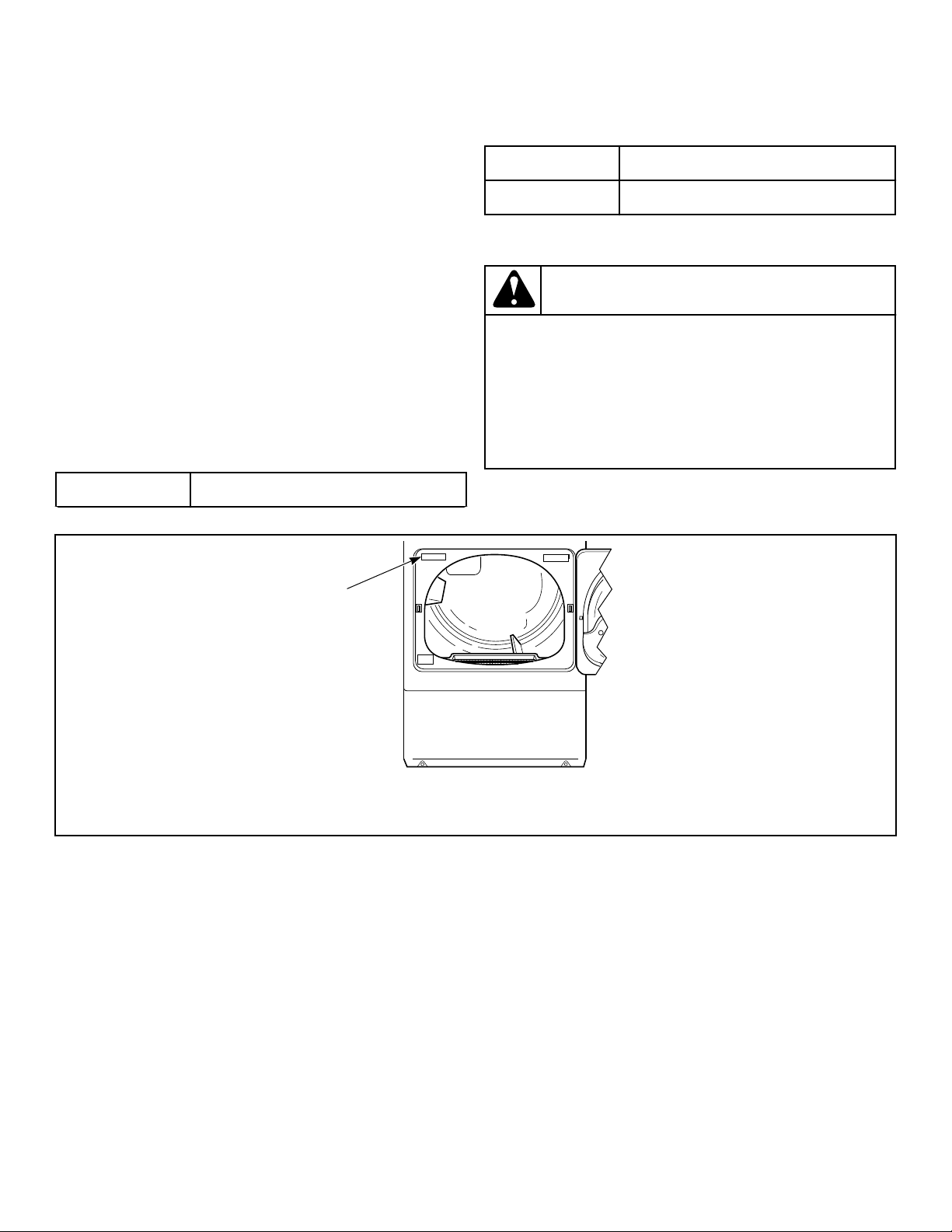
Contact Information
If service is required, contact the nearest Factory Authorized
Service Center.
If you are unable to locate an authorized service center or are un-
satisfied with the service performed on your unit, contact:
Alliance Laundry Systems
Shepard Street
P.O. Box 990
Ripon, WI 54971-0990
U.S.A.
www.alliancelaundry.com
Phone: +1 (920) 748-3121
When calling or writing about your unit, PLEASE GIVE THE
MODEL AND SERIAL NUMBERS. The model and serial num-
bers are located on the serial plate. The serial plate will be in the
location shown in Figure 55 .
Date Purchased
Table continues...
Model Number
Serial Number
Please include a copy of your bill of sale and any service receipts
you have.
WARNING
To reduce the risk of serious injury or death, DO NOT
repair or replace any part of the unit or attempt any
servicing unless specifically recommended in the
user-maintenance instructions or in published user-
repair instructions that you understand and have the
skills to carry out.
W329
If replacement parts are required, contact the source from where
you purchased your unit or call +1 (920) 748-3950 for the name
and address of the nearest authorized parts distributor.
DRY2527N_SVG
1
1. Serial Plate
Figure 55
Contact Information
©
Copyright, Alliance Laundry Systems LLC -
DO NOT COPY or TRANSMIT
50 Part No. 805420ENR4
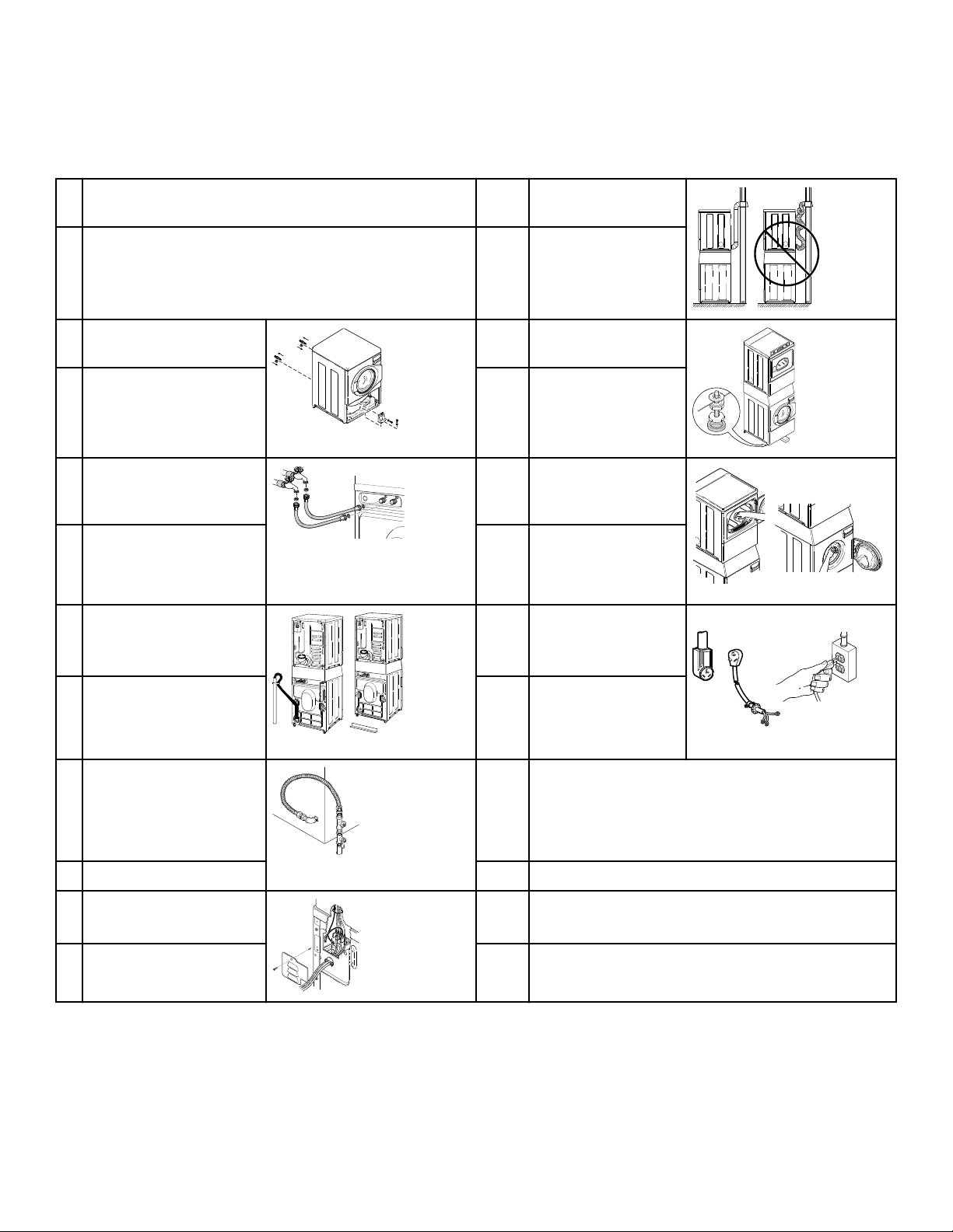
Installer Checklist
Fast Track for Installing the Stacked Washer/Dryer
1 Position Unit Near Installation Area. 7 Connect Dryer Exhaust
System.
SWD997N_SVG1
CHECK CHECK
2 Remove the Shipping Ma-
terials and Install Plugs.
FLW2359N_SVG
8 Position and Level the
Washer.
SWD1029N_SVG1
CHECK CHECK
3 Connect Fill Hoses.
FLW2304N_SVG
COLD
HOT
9 Wipe Out Inside of
Washer and Dryer
Drums.
SWD1030N_SVG
CHECK CHECK
4 Connect Drain Hose to
Drain Receptacle or Drain
Outlet to Drain System.
SWD1026N_SVG1
SWD1002N_SVG1
10 Plug In Washer and
Dryer.
DRY2669N_SVG
CHECK CHECK
5 GAS ONLY
• Connect Gas Supply
Pipe.
• Check for Gas Leaks.
D233I_SVG1
11 Recheck Steps.
CHECK CHECK
6 ELECTRIC ONLY - Con-
nect Electrical Cord
D679I_SVG1
12 Start and Run Dryer in Heat Setting to Verify Dryer is
Heating.
CHECK CHECK
Refer to the manual for more detailed information
Installer Checklist
©
Copyright, Alliance Laundry Systems LLC -
DO NOT COPY or TRANSMIT
51 Part No. 805420ENR4