Loading ...
Step 1
A. Checking:
» Make sure the Time Switch and the water heater VOLTAGES are the
same.
» Make sure the water heater rating in WATTS is not over the
maximum capacity of this Time Switch.
» Make sure the water heater is wired with COPPER wire.
Do not connect ALUMINUM wires to the terminals of this Time
Switch. Consult an electri cian if the existing wires are ALUMINUM.
Disconnect power at the circuit breaker(s) or disconnect switch(es)
before installing or servicing.
B. Planning and Measuring:
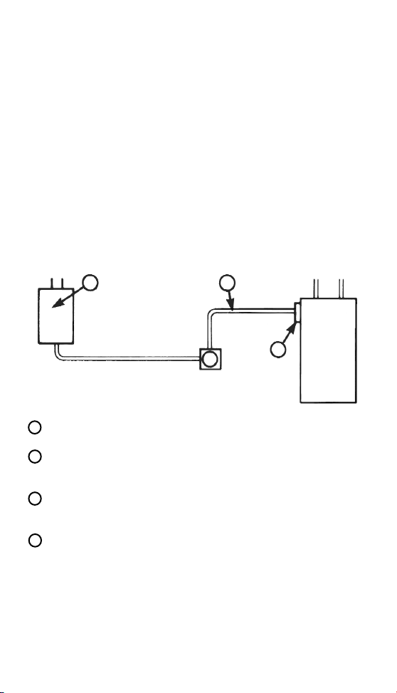
Here is how the water heater is wired now, BEFORE the installation of
this Time Switch:
Here is the modied wiring, AFTER the Time Switch is installed:
» Plan a convenient location for the Time Switch, preferably eye level
(also out of reach of small chil dren), and such that existing cable
(Fig. 2, or Fig. 3 ltem #3) may be utilized.
» Measure the distance (Item #5) from the Time Switch to Water
Heater Terminal Box (Item #4). Also measure dis tance (Item #3) from
Time Switch to Junction Box if existing cable (Fig. 2, ltem #3) is too
short. Allow for slack and 6 inches of hook-up leads at each end to
facili tate wiring connections.
C. Materials Needed
If the water heater is HARD WIRED: (See Figure 2)
• Obtain a piece of cable, the SAME TYPE (that is, metallic or
plastic) and SAME GAUGE with COP PER conductors to make ltem
#5 connection (and Item #3, if needed) as shown. See also gauge
selec tion chart below.
• Obtain 2 cable connectors (Item #6) to t the cable above.
If the water heater is CORD and PLUG connected: (See Figure 3)
• Obtain the SAME TYPE and GAUGE cordset with plug as presently
used on (Item #3) and 2 strain relief grommets (Item #7) to t THIS
cordset.
D. Tools Needed
Hammer, 1/4" wide screwdriver, drill, pliers, wire cutter and stripper.
Size of Fuse
or Circuit
Breaker
Minimum
Gauge of
Copper Wire
125 or 250
VAC
Water Heater Capacity
125 VAC 250 VAC
A #AWG A W W
15 14 15 1875 3750
20 12 20 2500 5000
25 10 25 3125 6250
Step 3
Mount timer case on wall as outlined in step 1B. Mark top mounting
hole. Drill hole in mounting surface and drive screw into hole. Hang
timer on screw. From the inside put screws into two bottom mounting
holes. Use anchors if necessary.
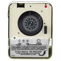
Step 5
Move insulator out of the way and connect the wires coming from the
service box and from the water heater to the terminals of the time
switch mechanism. For wiring connections re garding a specic model,
refer to diagram inside the time switch door. Attach wire ends to time
switch terminals as shown in wiring diagram. Insert only the stripped
copper ends of wires UNDER the pres sure plates of terminal screws as
shown. Using 3/16" or larger screwdriver, TIGHTEN TERMINAL
SCREWS FIRMLY (torque 20-30 Lb In.). Note: Time Switch may not
operate if terminal screws are loose. Now replace front insulator cover.
See illustration below.
1
2
3
4
Figure 1
Water
Heater
Water
Heater
Water
Heater
6
Time
Switch
Time
Switch
Figure 3: Cord and Plug ConnectedFigure 2: Hard Wired
2
3
5
4
4
7
2
5
3
Service Box - The water heater should have its own (separate)
fuse or circuit breaker in the electrical panel.
Junction Box - The wiring may or may not include this
convenience box. It may contain a disconnect switch and/or
receptacle if water heater is cord connected.
Water Heater Connection - This is a rigid or exible (metallic or
plastic) cable containing 2, 3 or 4 insulated wires of different
colors.
Water Heater Terminal Box - This is part of the water heater
where the power supply wires are connected.
Step 4
If the water heater is HARD WIRED:
Remove the cover of water heater terminal box (Fig. 1, Item #4). IS
ELECTRICITY TURNED OFF? NOTE COLORS OF WIRES.
Disconnect wires and cable connector. Remove the most convenient
knockout of the time switch case and attach cable (Fig. 2, Item #3) and
cable connector to case. If a 3/4 inch knockout is needed, remove the
1/2 inch knockout rst, then the 3/4 knockout. Pre pare another cable
(Fig. 2, ltem #5) by stripping the ends of wires 1/2 inch. Using cable
connec tor (Fig. 2, ltem #6), attach this cable to water heat er terminal
box and then the wires to water heater terminals.
NOTE: If there were green and/or white wires in the terminal box
before, connect the same colors to these same terminals. TIGHTEN
TERMINAL SCREWS FIRMLY (torque 20-30 Lb In.). Remove another
knockout of the time switch case and connect the other end of this
cable to the case, using the other cable connector, Item #6.
Mounting Holes
Knockouts
Hard Wired Cord and Plug Connected
Cable
Connectors
New Cordset with
Plug (Item #5)
Water Heater Cord
without Plug (Item #3)
Strain
Relief
Grommet
If the water heater is CORD and PLUG connected:
Remove plug at end of water heater cord (Fig. 1. Item #3). Split cord
about six inches and strip wire ends 1/2 inch. Remove the most
convenient knockout of the time switch case and attach cable (Fig. 2,
Item #3) and cable connector to case. If a 3/4 inch knockout is needed,
remove the 1/2 inch knockout rst, then the 3/4 knockout. Install strain
re lief grommet (Fig.3, Item #7) and attach cord to case as shown. Next,
install strain relief grommet to the other cordset (Fig. 3, Item #5) and
attach cord set to case as shown below.
Step 2
Disconnect power at the circuit breaker(s) or disconnect switch(es)
before installing or servicing. Pull plug, if cord connected; remove fuse
or open circuit breaker if hard wired. More than one circuit breaker or
disconnect switch may be required to de-energize the equipment
before servicing.
1
2
3
4
Page 2 Page 3
Page 4
Page 5
Electrical
Service
Box
To
Water Heater
From
Service Box
Pressure Plate
Terminal Screw
Make sure wire
insulation clears
pressure plate.
Grounding wire,
if required.
Loading ...
Loading ...
Loading ...