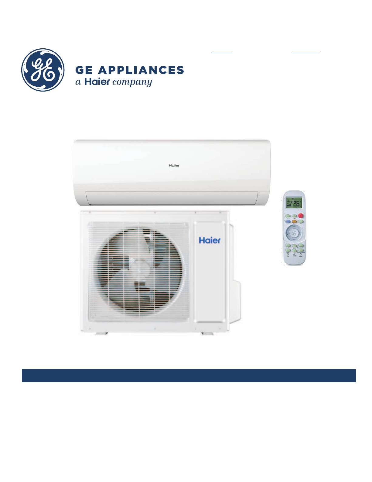
Ductless Split Heat Pump
Service Manual
Design may vary by model number.
• Please read this manual before installing this product.
• Keep this user manual for future reference.
PAGE 1
Safety Precautions/Introduction ................................................................................................. 3
Outdoor Unit Controls and Components ..................................................................................... 7
Indoor Unit Controls and Components ...................................................................................... 13
Sequence of Operation .............................................................................................................. 19
System Specications ............................................................................................................... 28
Error Codes and Troubleshooting .............................................................................................. 29
Reference Information .............................................................................................................. 62
Indoor
AW24TL2HFA
AW30TL2HFA
AW36TL2HFA
ASYW24TRDFA
ASYW30TRDFA
ASYW36TRDFA
Outdoor
1U24TL2HFA
1U3036TL2HFA
ASH124TRDFA
ASH3036TRDFA
Table of Contents

[This page intentionally left blank.]

INTRODUCTION PAGE 3
ENGLISH
Safety Precautions ............................................................................................................................................................. 4
Warnings and Cautions ....................................................................................................................................................................4
Introduction ....................................................................................................................................................................... 5
Introduction to the System ..............................................................................................................................................................5
SpecicationsforProperOperation ...............................................................................................................................................5
System Fundamentals ...................................................................................................................................................................... 5
Introduction
Table of Contents
INTRODUCTION
PAGE 4
ENGLISH
• Read these Safety Precautions carefully to ensure correct installation.
• This manual classies the precautions into WARNING and CAUTION.
• Be sure to follow all the precautions bellow: they are all important for ensuring safety.
!WARNING: Failure to follow any of WARNING is likely to result in grave consequences such as death or serious injury.
!CAUTION: Failure to follow any of CAUTION may in some cases result in grave consequences.
• The following safety symbols are used throughout this manual:
Be sure to observe this instruction Be sure to establish an earth connection Never attempt
• After completing installation, test the unit to check for installation errors. Give the user adequate instructions concerning the
use and cleaning of the unit according to the Operation Manual.
!WARNING
• Installation should be left to the dealer or another professional.
Improper installation may cause water leakage, electrical shock, or re.
• Install the heat pump according to the instructions given in this manual.
Incomplete installation may cause water leakage, electrical shock, or re.
• Be sure to use the supplied or specied installation parts.
Use of other parts may cause the unit to come lose, water leakage, electrical shock, or re.
• Install the heat pump on a solid base that can support the unit’s weight.
An inadequate base or incomplete installation may cause injury in the event the unit falls o the base.
• Electrical work should be carried out in accordance with the installation manual and the national electrical wiring rules or
code of practice.
Insucient capacity or incomplete electrical work may cause electrical shock or re.
• Be sure to use a dedicated power circuit. Never use a power supply shared by another appliance.
• For wiring, use a cable long enough to cover the entire distance with no connection.
Do not use an extension cord. Do not put other loads on the power supply, use a dedicated power circuit.
(Failure to do so may cause abnormal heat, electric shock or re.)
• Use the specied types of wires for electrical connections between the indoor and outdoor units.
Firmly clamp the interconnecting wires so their receive no external stresses. Incomplete connections or clamping may cause terminal over-
heating or re.
• After connecting interconnecting and supply wiring be sure to shape the cables so that they do not put undue force on the
electrical covers or panels.
Install covers over the wires. Incomplete cover installation may cause terminal overheating, electrical shock, or re.
• If any refrigerant has leaked out during the installation work, ventilate the room.
(The refrigerant produces a toxic gas if exposed to ames.)
• After all installation is complete, check to make sure that no refrigerant is leaking out.
(The refrigerant produces a toxic gas if exposed to ames.)
•When installing or relocating the system, be sure to keep the refrigerant circuit free from substances other than the
specied refrigerant(R410A), such as air or moisture.
(Any presence of air or other foreign substance in the refrigerant circuit causes an abnormal pressure rise or rupture, resulting in injury.)
• Be sure to establish a ground. Do not ground the unit to a utility pipe, arrester, or telephone earth.
In complete earth may cause electrical shock, or re. A high surge current from lightning or other sources may
cause damage.
!CAUTION
• Do not install this system in a place where there is danger of exposure to inammable gas leakage.
If the gas leaks and builds up around the unit, it may catch re.
• Establish drain piping according to the instructions of this manual.
Inadequate piping may cause ooding.
•Tighten the are nut according to the specied method such as with a torque wrench.
If the are nut is tightened too hard, the are nut may crack after a long time and cause refrigerant leakage.
• Maintain proper clearances around unit per this manual.
Safety Precautions

INTRODUCTION PAGE 5
ENGLISH
Introduction to the System
Single Zone Ductless Split System Heat Pumps feature a wall
mounted indoor fan/evaporator unit that receives refrigerant
from an inverter driven variable speed outdoor condensing
unit. The system operation is controlled with a remote
control.
The outdoor unit features a variable speed rotary
compressor, EEV metering device and DC fan motor. These
systems use R410A refrigerant and PVE oil. The outdoor units
are 208/230 volt rated systems. They come factory charged
for up to 25 ft. of interconnecting piping.
The indoor units are wall mounted. They feature a DC
blower motor and a DC louver motor. The unit has a room
temperature sensor and an evaporator tube temperature
sensor. The wall unit is powered by voltage from the outdoor
unit.
Specications for Proper Operation
• The systems are designed to operate in temperature ranges
of 60°F to 86°F in cooling mode and 60°F to 86°F in heat
mode.
• PVE oil is non-reactive to water and will not go into
hydrolysis. There is no need to add a refrigeration drier
when servicing or installing this system.
• The indoor wall mounted unit receives operating voltage
and communication data signals on #14 AWG wire that
connects between the indoor and outdoor units. There
should not be any splices in the eld wiring that goes
between terminals 1, 2, 3 and 4. A splice in these wires may
cause the system to lose communication between the
indoor and outdoor units. The system will then display an
error code E7.
• The eld-supplied refrigerant tubing connects using are
type ttings at both the indoor and outdoor units. Tubing
must be sized per the specications. Both lines must be
insulated. The only method of checking charge or adjusting
charge is by weight method explained in this manual (no
exceptions).
• The condensate system is a gravity type. A eld installed
condensate pump may be added to the system. Always
follow the manufacturer’s installation instructions when
installing a condensate pump.
• Proper clearances at both indoor and outdoor units must
be maintained. Improper clearances cause incorrect
refrigerant pressures and coil freezing.
System Fundamentals
The indoor unit will sense room temperature at the point
where the wall unit is installed. The indoor fan will run
continuously when placed in heating or cooling mode and
will not cycle on and o with the outdoor unit. If it did, room
temperature could not be sensed or maintained.
The inverter compressor system in the outdoor unit will vary
the refrigerant ow and indoor air volume levels to match
the comfort requirement inside the conditioned space. If an
abnormal condition is detected by the system’s sensors, the
system has the ability to take reactive measures.
The amount of refrigerant ow and associated capacity
generated by the system will be determined by how fast the
system’s variable speed rotary compressor is pumping. The
compressor operating speed is determined by the dierence
between the conditioned space temperature and the set
point.
If a large amount of capacity is needed, the compressor will
operate at a high speed. As the need for capacity reduces and
the temperature of the room nears set point, the compressor
will slow down. When set point has been reached, the
compressor will shut o while the fan continues to operate.
When a dierence in temperature is sensed between the
set point and room, the compressor will restart at a new
calculated speed.
If a system sensor determines there is a need to adjust
the frequency signal to prevent a system malfunction,
the compressor frequency may be over ridden and a new
frequency established. It should be noted that the frequency
signal level that is sent to the compressor cannot be
determined by a servicing technician.
In this manual, system components, operation, sensor
functions, and diagnostic procedures will be explained in
greater detail.
Introduction

INTRODUCTION
PAGE 6
ENGLISH
[Thispageintentionallyleftblank.]

OUTDOOR UNIT CONTROLS AND COMPONENTS PAGE 7
ENGLISH
Outdoor Unit Introduction ................................................................................................................................................. 8
Outdoor Component Identication .................................................................................................................................... 8
PCB .................................................................................................................................................................................... 9
Terminal Block .................................................................................................................................................................. 10
Power Factor Reactor ....................................................................................................................................................... 10
Compressor ..................................................................................................................................................................... 10
Outdoor Fan Motor ........................................................................................................................................................... 10
Discharge Temperature Sensor ........................................................................................................................................ 11
Defrost Temperature Sensor A ......................................................................................................................................... 11
Defrost Temperature Sensor B ......................................................................................................................................... 11
Ambient Temperature Sensor .......................................................................................................................................... 11
Suction Line Temperature Sensor ..................................................................................................................................... 11
Oil Separator .................................................................................................................................................................... 11
4-Way Valve ..................................................................................................................................................................... 12
Electronic Expansion Valve ............................................................................................................................................... 12
Accumulator .................................................................................................................................................................... 12
Refrigerant Strainers ........................................................................................................................................................ 12
GAS Liquid Segregator ..................................................................................................................................................... 12
Outdoor Unit Controls and Components
Table of Contents
OUTDOOR UNIT CONTROLS AND COMPONENTS
PAGE 8
ENGLISH
4
8
6
11
12
13
14
1
3
9
10
15
25
7
16 17
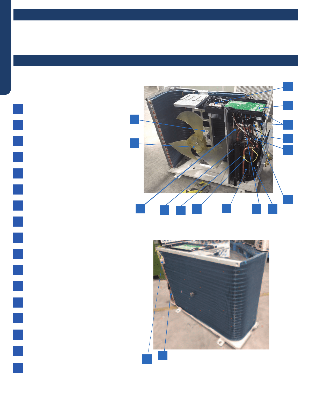
The outdoor unit has two circuit boards, an Inverter Power Module (IPM) that drives the compressor and main control board
(PCB) that manages system functions and inverter calculations.
Sensors monitor key temperatures throughout the system to manage operational decisions.
4-Way Valve
Accumulator
Compressor
Defrost Temperature Sensor
Discharge Temperature Sensor
Electronic Expansion Valve
Refrigerant Strainers
Ambient Temperature Sensor
Fan Motor
Power Factor Reactor
Suction Line Temperature Sensor
Terminal Block
Main Control Board (PCB)
Module Control Board (IPM)
Fan Blade
GAS Liquid Segregator
Oil Separator
1
2
3
4
5
6
7
8
9
10
11
12
13
14
15
16
17
Outdoor Unit Introduction
Outdoor Component Identication
OUTDOOR UNIT CONTROLS AND COMPONENTS PAGE 9
ENGLISH
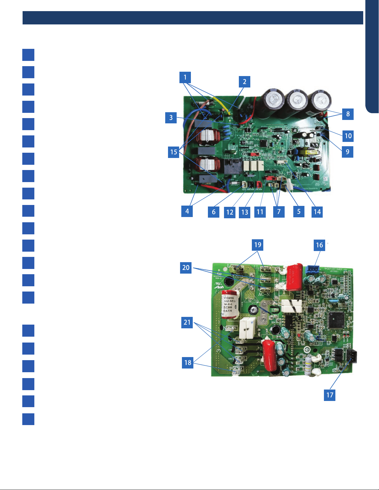
PCB (1) (Outdoor Control PCB)
PCB (2) (Module PCB for 09K )
2CN3 - Connector for ground
10 CN23 - 5VDC and 15VDC pulsing communication
connection between the PCB and the IPM
6CN10 - Connector for four way valve coil
4CNS and CN9 - 230 VAC power to the IPM
connections CN8 (or CN1) and CN9 (or CN2)
12 CN48 - Connector for the base pan heater
8CN28, CN25 - 310VDC power from the lPM
connections CN1 and CN3
CN1 and CN2 - 230 VAC power from terminal block
connections 1(N) and 2(L), CN6-connector for COM-N
1
CN18, CN20, CN31 - connections for
temperature sensors
7
CN4 -Communication connection between the
indoor board and the outdoor board
3
CN16 - Connector for the electronic
expansion valve
11
CN22 - Connector for DC POWER 15V
and 5V to the IPM
9
CN21- Connector for fan motor
5
CN49 - Connector for COMP heater
13
CN38 - Connector for diagnostic port
14
RV1, RV2, RV3 Varistor
15
CN10 - 5 VDC and 15 VDC power signal from PCB
connection CN22
16
CN11 - Connector for communication between the
control board and the module board
17
CN8, CN9 - 310 VDC single to PCB connections
CN28 and CN25
18
LI (CN3), LO (CN4) - Connector for reactor
19
CN1, CN2 - 230VAC signal from PCB connections CN8
and CN9
CN5, CN6, CN7 - Compressor U, V, and W connections
20
21
PCB
16
●
2
45
7
9
15
OUTDOOR UNIT CONTROLS AND COMPONENTS
PAGE 10
ENGLISH
The Reactor is a power lter. It is unlikely to ever have an
electrical failure of this component.
The Reactor of 24K, 30K and 36K is electrically connected to
the IPM on terminal connections CN3 and CN4.
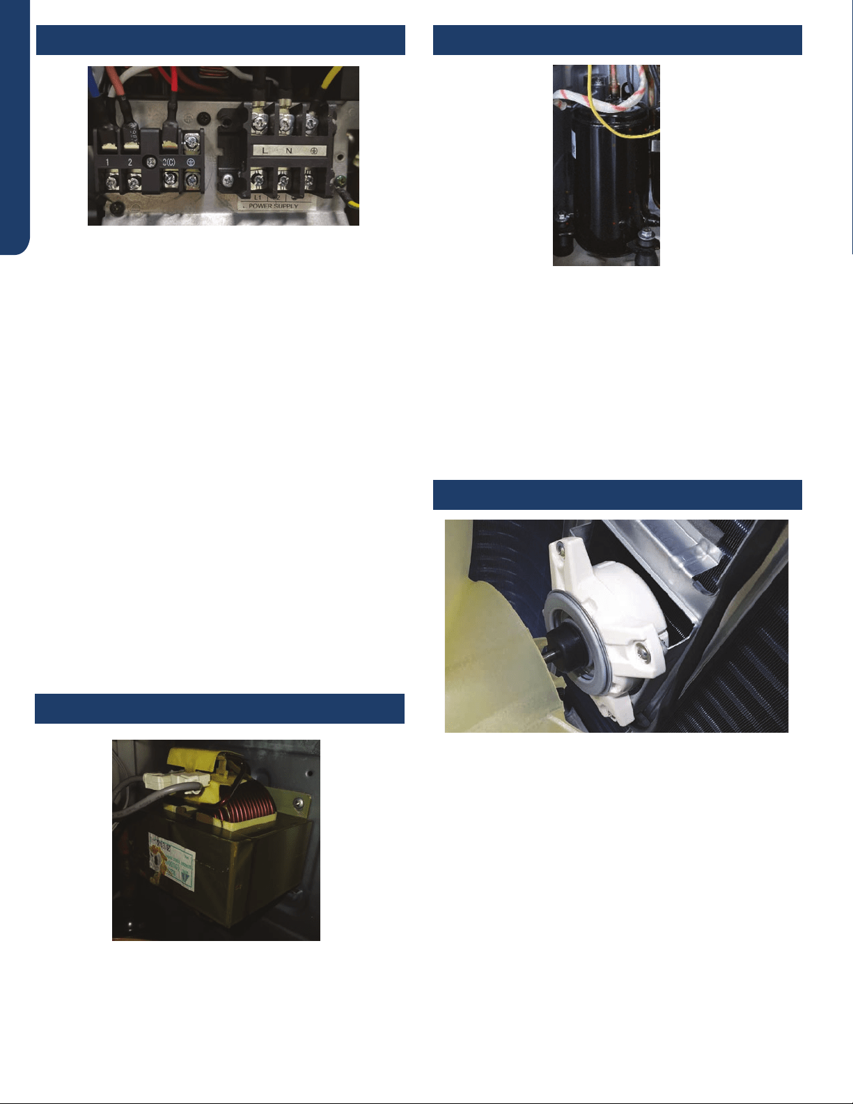
The outdoor unit is powered by 208/230 volt single phase
electricity connected at the terminal block. Terminals 1 L (L1)
and 2 N( L2) connect this voltage to the system.
The number 3 terminal is communication that connects wiring
between the indoor and outdoor units. A ground terminal
connects the outdoor unit to the line voltage power source.
Condensate safety switches should break the wire on terminal
2.
The indoor unit is also powered by the same electrical supply
as the outdoor unit. 14/4 stranded copper wire is connected
to the wiring terminal block at the outdoor unit and is run to
the same terminals on the indoor terminal block.
When installing the eld supplied wiring, make certain the
wire gauge is correct. There should not be any electrical
wiring splices between the indoor unit and outdoor unit wire
connection 3. This wire is used to carry communication data
between the indoor and outdoor units. A wiring splice where
wires are twisted in a wire nut may cause deformation of the
communication signal. If communication is lost between the
indoor and outdoor units, an ERROR CODE E7 will occur. (See
Page 36.)
The fan motor is a variable speed motor. The required speed is
calculated by the PCB. The motor is electrically connected to
the PCB via PLUG CN-21.
In COOL MODE, the motor will slow down as outdoor air
temperature falls. In HEAT MODE, the motor will increase
speed as the outdoor air temperature falls.
The compressor is a three phase DC inverter driven rotary
type, capable of variable speed operation. The compressor
operating frequency will be determined by the temperature
dierence between set point and room temperature.
The compressor of 24K, 30K and 36K is electrically connected
to the IPM on terminal connections CNS, CN6 and CN7.
Protection of the compressor will be provided by the
discharge temperature sensor, the suction line temperature
sensor, and the overcurrent protection parameter in the PCB.
Terminal Block Compressor
Power Factor Reactor
Outdoor Fan Motor
OUTDOOR UNIT CONTROLS AND COMPONENTS PAGE 11
ENGLISH
The Defrost Temperature Sensor A is a negative coecient
thermistor that will change resistance in response to outdoor
coil temperature changes. The PCB monitors the temperature
of the outdoor coil to determine when the system should
perform a defrost cycle. The sensor also monitors coil
temperature during defrost cycles to determine termination
conditions.
This sensor connects to the Main Control Board at PLUG CN-
31.
The Defrost Temperature Sensor B is a negative coecient
thermistor that will change resistance in response to outdoor
coil temperature changes. The PCB monitors the temperature
of the outdoor coil to determine when the system should
perform a defrost cycle. The sensor also monitors coil
temperature during defrost cycles to determine termination
conditions.
This sensor connects to the Main Control Board at PLUG CN-
20.
The Discharge Temperature Sensor is a negative coecient
thermistor that senses the temperature of the compressor
hot gas. The PCB monitors the temperature of the
compressor hot gas and will make inverter speed changes in
response to input from this device.
This sensor connects to the Main Control Board at PLUG CN-
20.
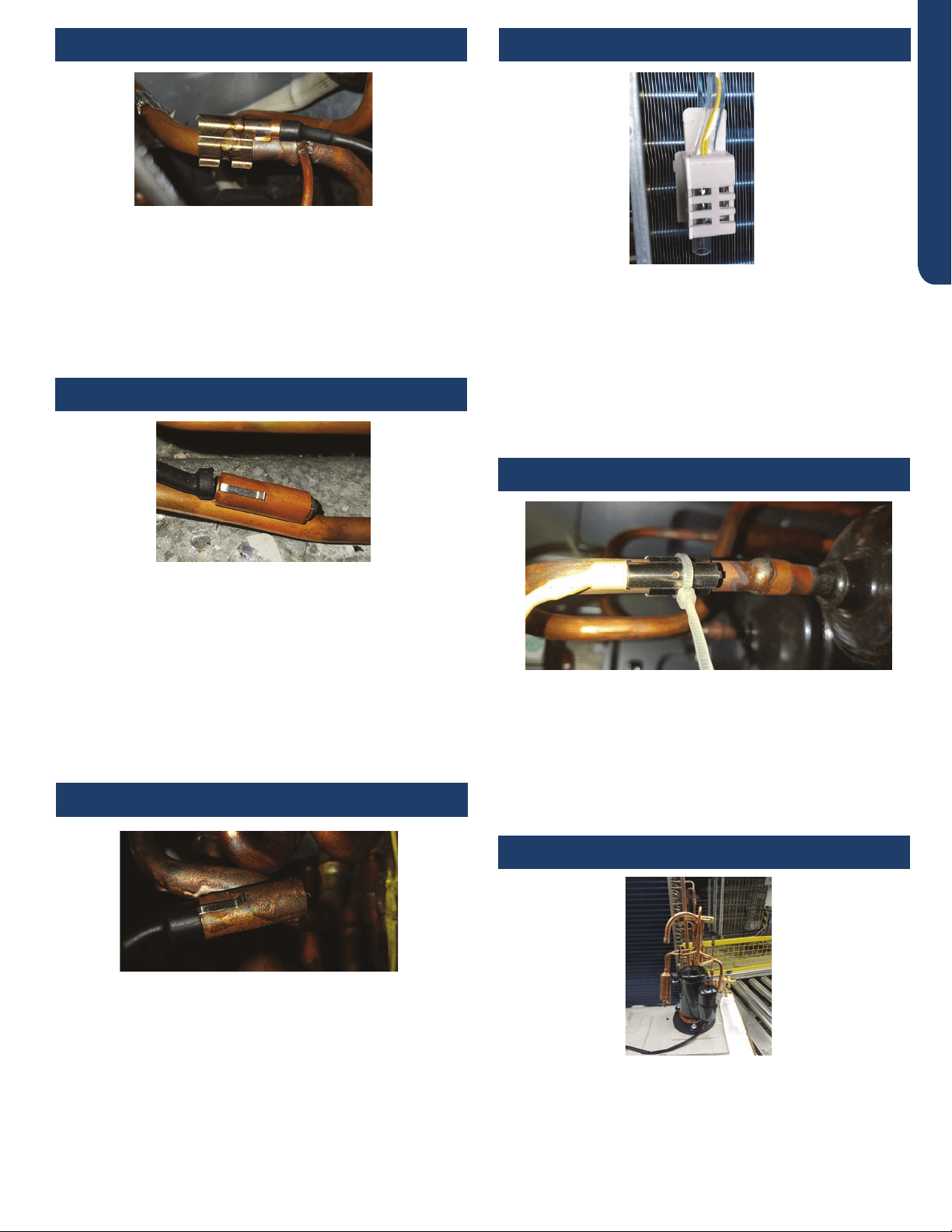
The Suction Line Temperature Sensor is a negative coecient
thermistor that senses the temperature of the suction line.
The PCB monitors the temperature of the suction line and the
EEV operation to maintain an acceptable superheat.
This sensor connects to the Main Control Board at PLUG CN-
18.
The oil separator is integrated on the exhaust pipe. When
the compressor oil passes through the exhaust pipe, it is
separated by the oil separator, then returns to the air return
pipe through the oil return capillary,and then returns to the
compressor.
The Ambient Temperature Sensor is a negative coecient
thermistor that will change resistance in response to outdoor
air temperature changes. The PCB monitors the temperature
of the outdoor air to determine fan speed requirements and
inverter speed. The sensor also plays a role in calculation of
required defrost conditions.
This sensor connects to the Main Control Board at PLUG CN-
20.
Discharge Temperature Sensor
Defrost Temperature Sensor A
Defrost Temperature Sensor B
Ambient Temperature Sensor
Suction Line Temperature Sensor
Oil Separator
OUTDOOR UNIT CONTROLS AND COMPONENTS
PAGE 12
ENGLISH
The metering device is an electronic expansion valve. The
valve consists of an electrical operator and a valve body with
internal variable size orice. When operating, the PCB will
send pulses of voltage to the electrical operator. The operator
will then magnetically move the position of the metering
orice pin to vary refrigerant ow.
The metering device position is determined by input from
a Suction Line Temperature Sensor. The EEV will change
the internal orice size to maintain an acceptable level of
superheat.
During COOL MODE the valve meters low pressure
refrigerant to the indoor coil. During HEAT MODE the valve
meters low pressure refrigerant to the outdoor coil.
The electrical expansion valve is electrically connected to the
Main Control Board at PLUG CN-16.
The 4-Way Valve redirects the ow of refrigerant in the piping
circuit to allow the system to reverse the functions of the
indoor and outdoor coils. When de-energized in COOL MODE,
the valve will direct the refrigerant hot gas to the outdoor coil.
When energized in HEAT MODE, the valve will direct the hot
gas to the indoor coil.
The valve ow direction capability is controlled by an electrical
solenoid. When energized with 230 VAC, the solenoid will
magnetically move an internal slide within the 4-Way Valve to
change the direction of refrigerant ow.
The 4-Way Valve is electrically connected to the Main Control
Board at PLUG CN-10.
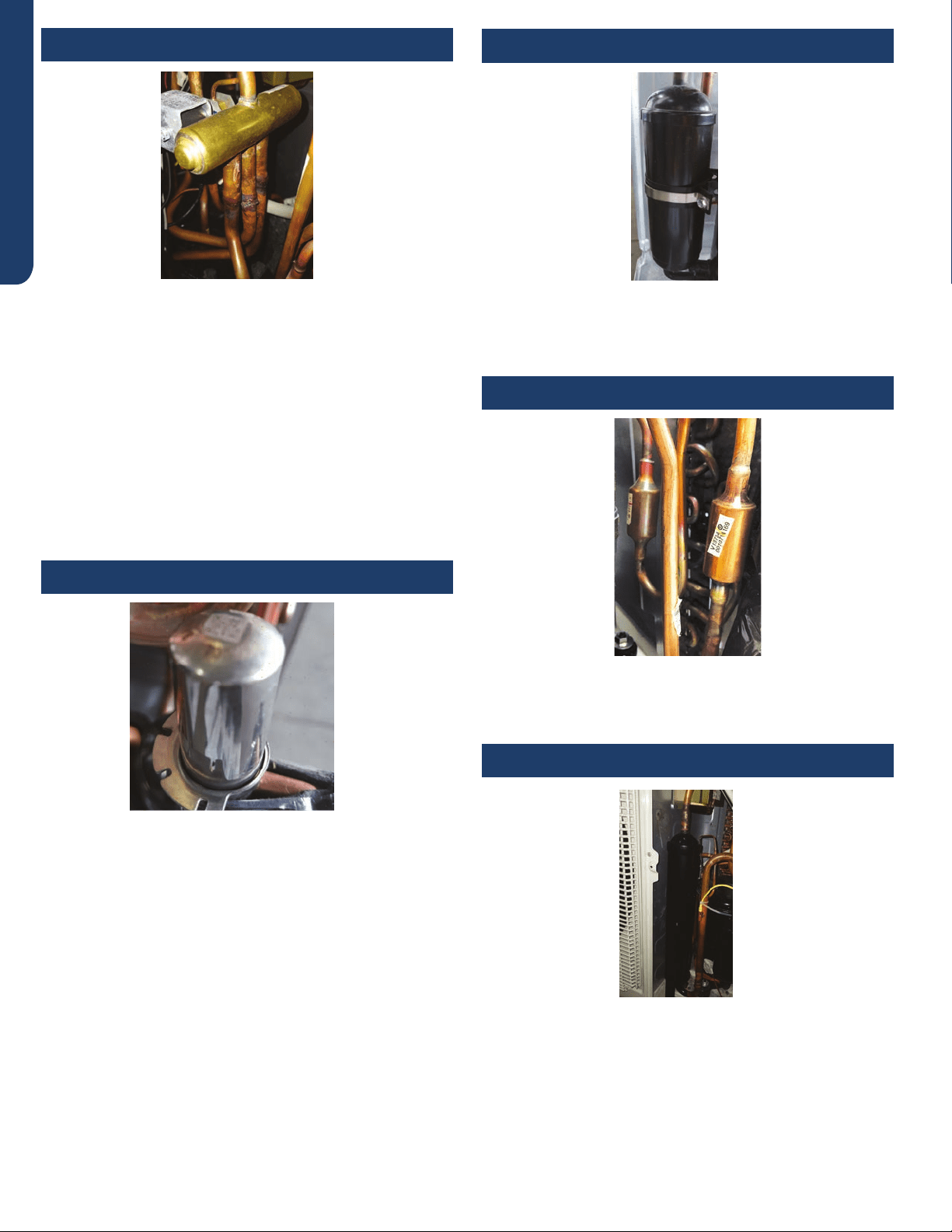
The Accumulator is located in the suction line circuit at the
entrance to the compressor. The accumulator helps prevent
liquid refrigerant from entering the compressor during run
operation.
The system has debris-catching strainers that protect internal
system components from contaminants in the refrigerant.
The strainer is a permanent part that is not typically replaced.
The liquid and gas seperator is located on the suction line
circuit before accumulator. It can help prevent the liquid
refrigerant entering the compressor during the operation.
4-Way Valve Accumulator
Refrigerant Strainers
GAS Liquid Segregator
Electronic Expansion Valve

INDOOR UNIT CONTROLS AND COMPONENTS PAGE 13
ENGLISH
Indoor Unit Introduction .................................................................................................................................................. 14
Indoor Component Identication ..................................................................................................................................... 14
Indoor Control Board ........................................................................................................................................................ 15
Terminal Block .................................................................................................................................................................. 16
Display ............................................................................................................................................................................. 16
Ambient Temperature Sensor .......................................................................................................................................... 16
Piping Temperature Sensor .............................................................................................................................................. 16
Stepper Louver Motor ...................................................................................................................................................... 17
Fan Motor ......................................................................................................................................................................... 17
Emergency Button ........................................................................................................................................................... 17
DIP Switch and DIP Switch Settings .................................................................................................................................. 18
Indoor Unit Controls and Components
Table of Contents
INDOOR UNIT CONTROLS AND COMPONENTS
PAGE 14
ENGLISH
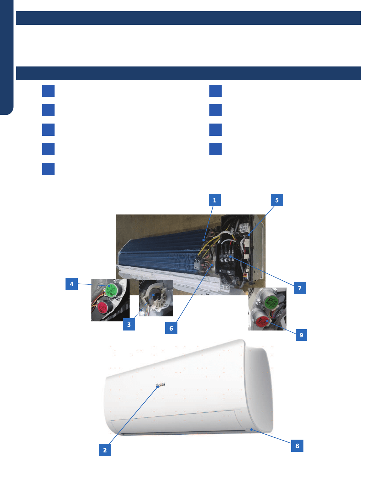
The indoor unit is mounted high on the wall to provide comfort and air movement within the conditioned space. Features of the
system include: Variable speed blower operation that speeds up and slows down with changes in demand, moving louvers to
direct air, indoor air temperature sensing, evaporator coil temperature sensing, a status display, evaporator coil with metering
device located in outdoor unit, and an emergency ope ration button.
Ambient Temperature Sensor
Display
Fan Motor
Louver Motor
PCB
1
2
3
4
5
Piping Temperature Sensor
Terminal Block
Emergency Button
Louver Motor
6
7
8
9
Indoor Unit Introduction
Indoor Component Identication
INDOOR UNIT CONTROLS AND COMPONENTS PAGE 15
ENGLISH
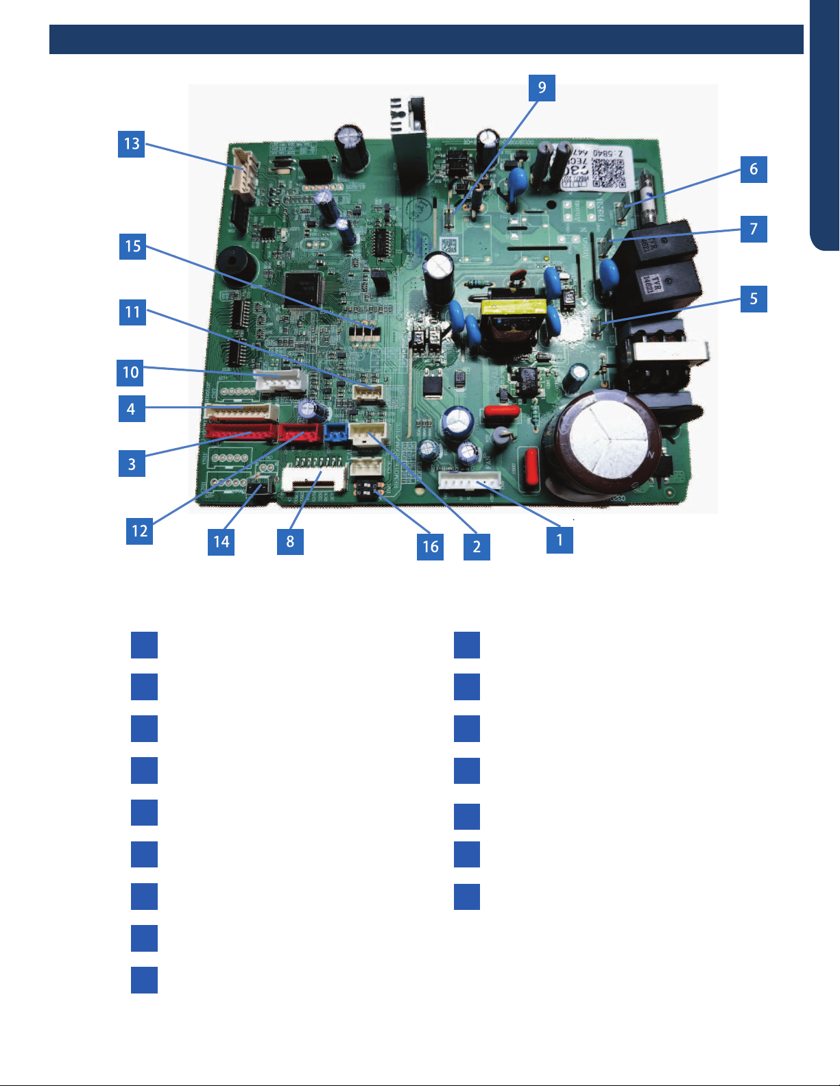
2CN6 - Connector for pipe temperature sensor
and room temperature sensor
4CN5 - Connector for UP/DOWN STEP motor 2
9CN23 - Communication connection between
the PCB and the outdoor unit
6CN17 - Connector for power L
11 CN56-Connector for occupancy sensor
CN14-Connector for forced operation
ON/ OFF switch
13 CN38-Connector for diagnostic port
CN9-Connector for fan motor
1
CN7 - Connector for display board
8
CN21 - Connector for power N
5
CN34-Connector for wired controller interface
12
15
16
CN5-1 - Connector for UP/DOWN STEP
motor 1
3
CN35-Connector for WiFi module
10
CN27 - Connector for GND
7
14
JS-Select remote code A or B
J6-Select room card able or disable
BMl 1-2 Select 23, 26, 33, or 35
Indoor Control Board
INDOOR UNIT CONTROLS AND COMPONENTS
PAGE 16
ENGLISH
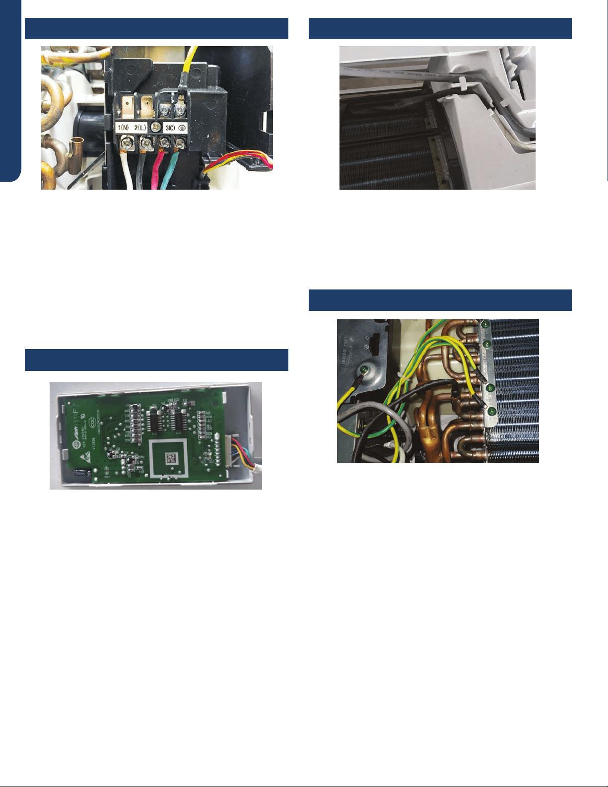
The unit terminal block receives electrical power from the
outdoor unit. There are 4 connections for electrical wires.
Terminals 1 and 2 are connected to terminals 1 and 2 of the
outdoor unit. This wiring supplies power to the indoor unit.
Terminal 3 is a communication wire. The indoor unit sends
indoor air temperature, coil temperature and temperature
setpoint information to the outdoor unit on this wire. If a
splice or break in this wire is present, the indoor unit will not
be able to communicate with the outdoor unit. The ERROR
CODE will be an E7.
The indoor display has an infrared communication circuit that
receives operating commands from the remote control. This
display will indicate operating modes, error codes, indoor air
temperature, timer status, and power status.
The Ambient (room) Temperature Sensor is a negative
coecient thermistor that will decrease in resistance with
increases in room air temperature. The sensor is located on a
clip mounted in the return air stream.
The sensor connects to the control board at Plug CN-6.
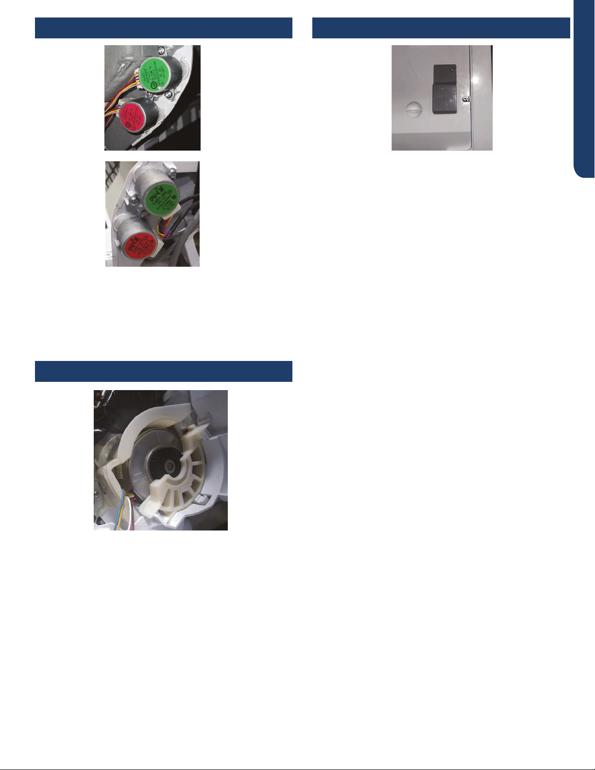
The Piping Temperature Sensor is a negative coecient
thermistor that will decrease in resistance with increases in
coil temperature. The sensor is located in a socket soldered to
the surface of the indoor coil.
This sensor will monitor the temperature of the indoor coil
in both cooling and heating modes of operation. Should
abnormally cold or hot coil temperature be detected by this
sensor, the system will take functional corrective steps to
correct the condition or report an ERROR CODE.
The sensor connects to the control board at Plug CN-6.
Terminal Block Ambient Temperature Sensor
Piping Temperature Sensor
Display
INDOOR UNIT CONTROLS AND COMPONENTS PAGE 17
ENGLISH
The Fan Motor is a variable speed motor. The air volume will
vary with the speed of the compressor, or it can be set at the
remote control to maintain a single speed.
The Fan Motor is connected to the indoor control board via
PLUG CN-9.
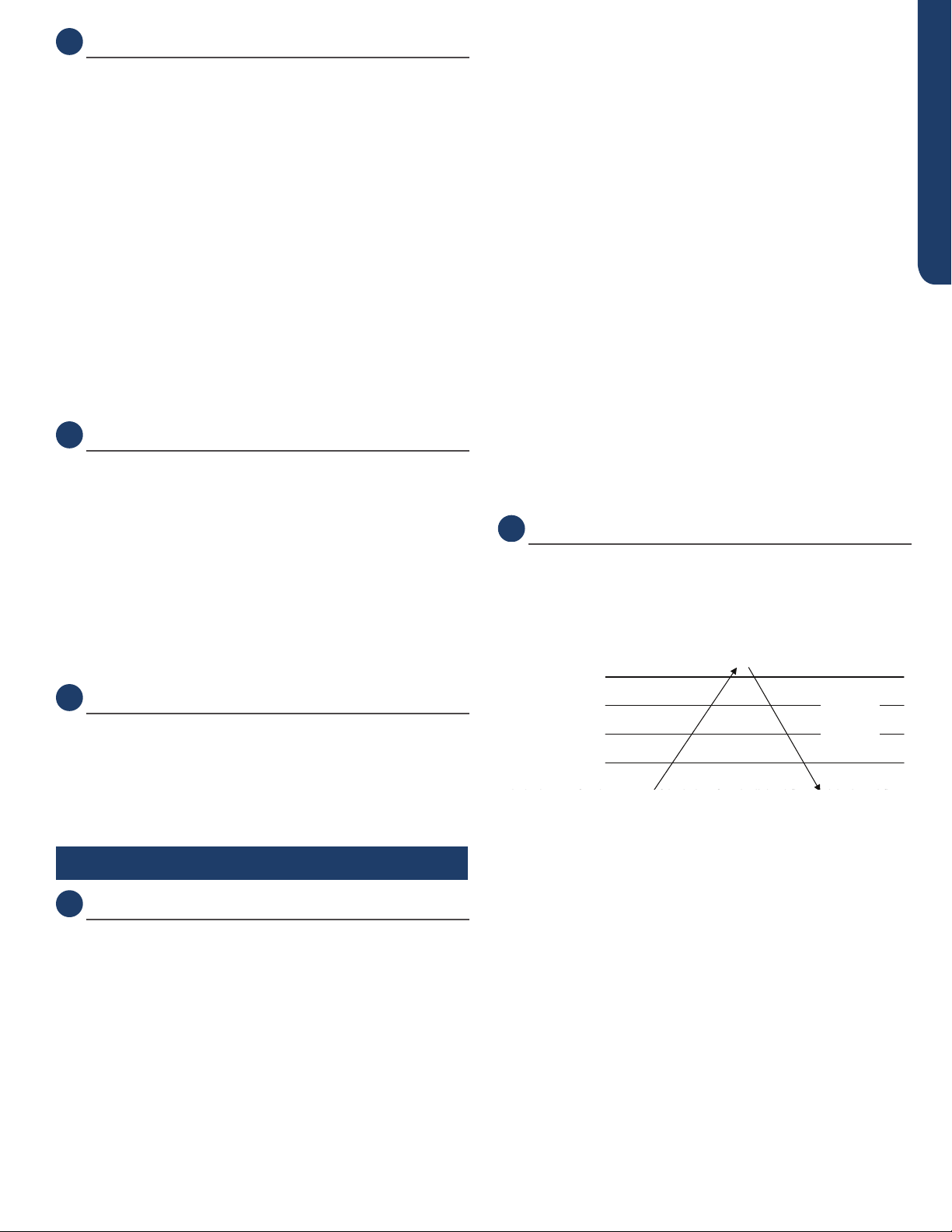
If the remote control is non-functional, the Emergency
Button can be used. 73F -78F degrees will be maintained, until
commands are received via the remote control.
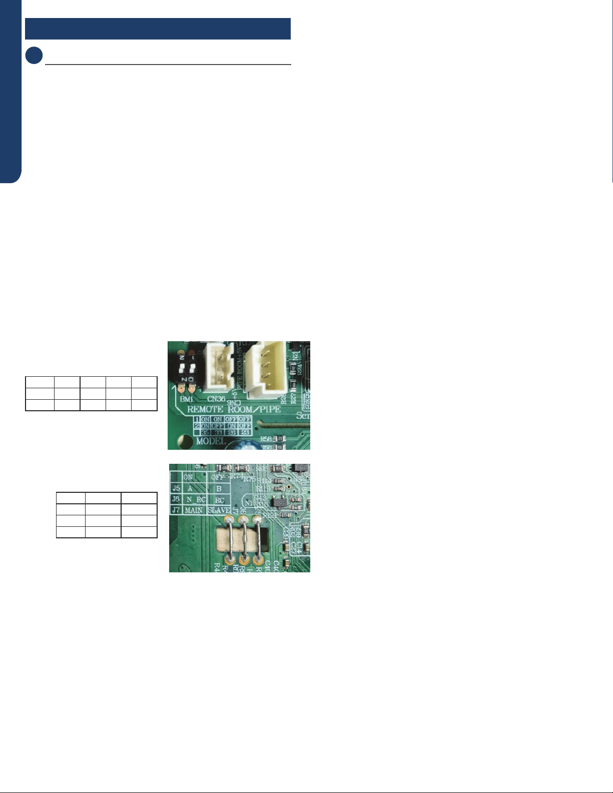
The STEPPER MOTOR 1 and 2 moves the louver up or down,
depending upon selections made at the remote control.
The motor is connected to the indoor control board at CN5
and CN5-1
Stepper Motor Louver
Fan Motor
Emergency Button
REMOTE CONTROL FUNCTIONS
PAGE 18
ENGLISH
DIP Switch Settings
The PCB has a set of DIP switches that must be set when
replacing the PCB.
The replacement PCB is shipped with all switches set to the OFF
position.
Switch settings:
J5 Selects remote code A or B. Normally set to connection state
for code A operation. If two indoor units are used in the same area
and the user wishes to control them separately, switch J5 of the
second unit is set to the disconnected state for code B operation.
The wireless remote for the second unit is also set to code B.
J6 Selects room card able or disable. Normally set to connected
state. Set to the disconnected state when used in conjunction
with a room card interface utilized in hotel rooms.
SW-1 and SW-2 Selects EEPROM codes 23, 26, 33 and 35.
Set to identify the tonnage of the unit.
Settings:
1 ON ON OFF OFF
2ON OFF ON OFF
35 33 26 23
DIP Switch
ON OFF
J5 AB
J6 N-RC RC
J7 MAIN SLAVE

SEQUENCE OF OPERATION PAGE 19
ENGLISH
System Power .................................................................................................................................................................. 20
Cool Mode ........................................................................................................................................................................ 20
Overview ........................................................................................................................................................................................ 20
Indoor Unit ..................................................................................................................................................................................... 20
Indoor Temperature Sensors ....................................................................................................................................................... 20
Communication ............................................................................................................................................................................. 20
OutdoorUnit ................................................................................................................................................................................. 20
OutdoorTemperatureSensors .................................................................................................................................................... 21
Call to Terminate Cooling ............................................................................................................................................................. 21
FreezeProtectionFunction .......................................................................................................................................................... 21
Heat Mode ........................................................................................................................................................................ 21
Overview ........................................................................................................................................................................................ 21
ColdAirProofOperation .............................................................................................................................................................. 21
Defrost ........................................................................................................................................................................................... 22
Automatic Heating Temperature Compensation ....................................................................................................................... 22
Indoor Unit ..................................................................................................................................................................................... 22
Indoor Temperature Sensors ....................................................................................................................................................... 22
Communication ............................................................................................................................................................................. 22
OutdoorUnit ................................................................................................................................................................................. 22
OutdoorTemperatureSensors .................................................................................................................................................... 22
Call to Terminate Heating ............................................................................................................................................................. 22
Auto Mode........................................................................................................................................................................ 23
Dry Mode ......................................................................................................................................................................... 23
Overview ........................................................................................................................................................................................ 23
Indoor Unit ..................................................................................................................................................................................... 23
Indoor Temperature Sensors ....................................................................................................................................................... 23
Communication ............................................................................................................................................................................ 23
OutdoorUnit ................................................................................................................................................................................. 23
OutdoorTemperatureSensors .................................................................................................................................................... 23
Defrost Operation ............................................................................................................................................................ 24
Protection Functions ........................................................................................................................................................ 24
HighTemperatureProtection ...................................................................................................................................................... 24
OverheatingProtectionforIndoorUnit ....................................................................................................................................... 24
CompressorOver-CurrentProtection ........................................................................................................................................ 24
Anti-freezeProtectionoftheCoil ............................................................................................................................................... 25
Special Functions ............................................................................................................................................................. 25
Auto Restart .................................................................................................................................................................................. 25
TimedDefrost ............................................................................................................................................................................... 25
DemandDefrost ............................................................................................................................................................................ 25
Indoor Temperature Display ......................................................................................................................................................... 25
Temperature Compensation ........................................................................................................................................................ 25
SmartHQ ........................................................................................................................................................................................ 26
Estar6.1 .......................................................................................................................................................................................... 26
Sequence of Operation
Table of Contents

SEQUENCE OF OPERATION
PAGE 20
ENGLISH
The 240 Volt AC power for the system connects to terminals
1(N), 2(L), and ground of the outdoor unit terminal block. This
terminal block also has terminals to connect power to the
indoor unit.
The voltage readings between terminals 1(N) and ground, and
terminals 2(L) and ground should be 120 VAC. The voltage
reading between terminals 1(N) and 2(L) should be 240 VAC.
One additional connection on the terminal block (3) is for the
communication wire between the indoor and outdoor units.
NOTE: Mis-wiring of these connections may cause improper
operation or damage to system components.
Cool Mode
Overview
The temperature control range in cooling mode is 60°F - 86°F.
The temperature set by the remote control and the indoor
unit ambient temperature sensor will determine if a call for
cooling is needed. If a call for cooling is justied, the call is
communicated from the indoor unit to the outdoor unit. The
indoor unit louver will open using a stepper motor, and the
indoor fan will operate at the speed last set. The outdoor unit
will determine the position of the EEV and speed frequency
of the compressor. There can be a delay of up to 3 minutes
before the outdoor unit fan and compressor start.
The speed of the indoor fan can be controlled manually by
the user or automatically by the system. The speed can be
changed between LOW, MEDIUM, and HIGH.
The predetermined conditions for automatic control are as
follows:
(Tr = room temperature Ts = set temperature)
High Speed: Tr ≤ Ts + 5.4°F
Medium Speed: Ts + 1.8°F ≤ Tr < Ts + 5.4°F
Low Speed: Tr ≤ Ts + 1.8°F or when the sensor is o.
There will be a 2 second delay when manually controlling the
speed.
The outdoor unit temperature sensors: outdoor ambient,
defrost, suction line, and compressor discharge, used in con-
junction with the indoor temperature sensors, indoor ambient
and coil, provide information to the outdoor control board
to monitor the system and regulate the frequency of the
compressor, the EEV, and outdoor fan speed, to achieve the
desired room temperature.
When the call for cooling has been satised, the outdoor unit
compressor will turn o, followed by the outdoor fan. The
indoor unit fan will continue to run.
If the system detects a malfunction, it may shut down or show
an error code. This code will be shown on the indoor display
board or a ashing LED will appear on the outdoor PCB.
Indoor Unit
The signals received by the infrared receiver are relayed to the
main board of the indoor unit to turn the system on and set it
to cool mode.
The indoor unit PCB will illuminate the display, indicating the
set temperature and current status of the unit. The PCB will
signal the stepper motor to open the louver to either a sta-
tionary position, or one of several oscillating modes.
As the louver opens, the indoor unit main board will power up
the indoor fan motor, operating the fan at the speed last set.
The indoor fan motor has a feedback circuit which provides
the indoor unit main board with information for controlling the
speed of the fan motor.
Indoor Temperature sensors
The indoor unit has two sensors that provide temperature in-
formation to the main board. An indoor ambient temperature
sensor and pipe temperature sensor are used for controlling
the system during cool mode.
The resistance values of the sensors will vary with tempera-
ture. The resistance to temperature values can be found using
a temperature / resistance chart specic to the sensor being
checked.
Communication
The indoor and outdoor unit main boards communicate via a
digital signal on the wire connected to terminal 3 of each unit.
A splice or break in this wire will cause a communication error.
When a command is received from the remote control, the
indoor unit main board communicates with the outdoor unit
main board to perform the requested function.
Outdoor Unit
Upon a request for cooling, the outdoor unit main board
applies power to the outdoor fan motor and compressor. De-
pending on system cycling, there may be up to a 3 minute wait
period before the compressor and outdoor fan start.
WARNING: Do not measure compressor voltages as damage
to the meter may result.
If the room temperature is less than the set temperature, yet
higher than 2°F below the set temperature, the system will
adjust the speed of the compressor automatically.
The outdoor unit main board also controls the position of
the EEV (Electronic Expansion Valve) to regulate the ow of
refrigerant to the indoor unit evaporator coil.
System Power
SEQUENCE OF OPERATION PAGE 21
ENGLISH
Outdoor Temperature Sensors
Five temperature sensors located in the outdoor unit provide
temperature information to the outdoor unit main board for
control of the system during cool mode.
The outdoor ambient temperature sensor provides the tem-
perature of the air drawn into the condenser coil.
The defrost temperature sensor A provides the temperature
sensed at the output of the condenser coil.
The defrost temperature sensor B provides the temperature
sensed at the middle of the condenser coil.
The suction line temperature sensor provides the tempera-
ture sensed at the incoming suction line pipe.
The compressor discharge sensor provides the temperature
sensed at the discharge pipe of the compressor.
Call to Terminate Cooling
The system will terminate cooling when the indoor ambient
temperature sensor is equal to or lower than 2°F of the room
set temperature. The indoor control board will communicate
to the outdoor control board to de-energize the compressor.
The outdoor fan will run for 60 seconds before stopping.
The indoor fan motor and louver will continue operating after
cooling has been terminated.
To stop cool mode, press the power button to turn the system
o, or change to another mode.
Freeze Protection Function
When the compressor operates continuously for 10 seconds
and the temperature of the indoor coil has been below 32°F
for 10 seconds, the compressor will stop. The indoor unit fan
will continue to operate. When the temperature of the indoor
coil rises to 45°F for more than 3 minutes the compressor will
restart and the system will continue functioning.
Heat Mode
Overview
The temperature control range in heating mode is 60°F - 86°F.
The temperature set by the remote control and the indoor
unit ambient temperature sensor will determine if a call for
heat is needed. If a call for heat is justied, a temperature
compensation adjustment is automatically added to the oper-
ating parameter and the call is communicated from the indoor
unit to the outdoor unit.
The indoor unit louver will open using a stepper motor. The
indoor fan will not operate at this time.
The outdoor unit will shift the 4-way valve to the heat mode
position and determine the position of the EEV and speed
(frequency) of the compressor. There can be a delay of up to 3
minutes before the outdoor unit fan and compressor start.
(Tr = room temperature Ts = set temperature)
If Tr ≤ Ts, the outdoor unit will operate and the indoor fan oper-
ates in cold air prevention function
If Tr > Ts, the outdoor unit turns o and the indoor fan oper-
ates at heat residue sending mode.
If Tr < Ts, the outdoor unit will restart and the indoor fan oper-
ates in cold air proof mode.
The speed of the indoor fan can be controlled manually by
the user or automatically by the system. The speed can be
changed between HIGH, MEDIUM, and LOW. The predeter-
mined conditions for automatic control are as follows:
High Speed: Tr < Ts
Medium Speed: Ts ≤ Tr ≤ Ts + 4°F
Low Speed: Tr > Ts + 4°F
When the indoor fan is running in automatic mode when the
speed switches from high to low, the indoor fan will maintain
high speed for a period of 3 minutes before switching to low
speed.
Cold Air Proof Operation
At initial start of heat mode, indoor blower will not be turned
on immediately until indoor coil temperature senses a mini-
mum temperature. This period usually takes 30 seconds to 3
minutes depending on the outdoor ambient temperature.
ćć
2. 4 minutes after the start up of the indoor fan, the light airflow and the low airflow wi
Heat start temp 1
Heat start temp
2
Heat start temp
3
Heat start temp
4
Set speed
Low speed
Light speed
Fan/off
Fan/off
Keep the hig
h
speed. The fa
n
doesn’t stop
4 minutes after the indoor fan starts, the light or low speed will
switch to the set speed.
Residual heat sending: the indoor fan will operate on low
speed until coil temperature reaches 73°F.
The outdoor unit temperature sensors, including outdoor am-
bient, defrost, suction line, and compressor discharge, used
in conjunction with the indoor coil and room temperature
sensors, provide information to the outdoor control board to
monitor the system and regulate the speed of the compres-
sor, the EEV, and outdoor fan speed to achieve the desired
room temperature.
When heating has been satised, the outdoor unit compres-
sor will turn o rst and followed by the outdoor fan. The
4-way valve will de-energize 2 minutes after compressor
stops.

SEQUENCE OF OPERATION
PAGE 22
ENGLISH
The indoor unit fan will continue to run at minimum speed until
indoor coil temperature reaches a minimum temperature,
when it will turn o.
If the system detects a malfunction, it may shut down or show
an error code on the indoor unit display board and/or outdoor
unit main board LED.
Defrost
When the system initiates a call for defrost, the indoor fan
motor stops. The indoor unit display will not change. Any
indoor unit malfunctions will be ignored at this time. The sys-
tem will cycle through the defrost operation. Any indoor unit
malfunctions will be ignored until the compressor restarts
and has been operating for 30 seconds. At the conclusion of
the defrost cycle, the indoor fan will enter the cold air proof
operation. Heat mode resumes.
Automatic Heating Temperature Compensation
When the system enters heating mode, a temperature com-
pensation adjustment is added to the operating parameter.
This adjustment is canceled when exiting heat mode.
Indoor Unit
To enter the heat mode, point the infrared remote controller
at the indoor unit and press the power button, then press the
HEAT mode button if not already set to heat mode.
The signals received by the infrared receiver are relayed to the
main board of the indoor unit to turn the system on and set it
to heat mode.
The indoor unit PCB will activate the display of the indoor unit,
illuminating the display and indicating the set temperature
and current status of the unit.
The indoor unit PCB will signal the stepper motor to open the
louver to a stationary position.
The PCB will power up the indoor fan motor after the out-
door unit has started and heating of the indoor coil has taken
place (see cold air proof operation). The motor has a feedback
circuit which provides information for controlling the speed of
the fan motor.
Indoor Temperature Sensors
The indoor unit has two sensors that provide temperature in-
formation to the indoor unit main board. The sensors: a room
temperature sensor, and pipe temperature sensor, are used
for controlling the system during heat mode.
The resistance values of the sensors will vary with tempera-
ture. The resistance to temperature values can be found using
a temperature /resistance chart specic to the sensor being
checked.
Communication
The indoor and outdoor unit main boards communicate via a
digital signal on the wire connected to terminal 3 of each unit.
A splice or break in this wire will cause a communication error.
When a command is received from the remote control, the
indoor unit main board communicates with the outdoor unit
to perform the requested function.
Outdoor Unit
Upon a request for heat, the outdoor unit PCB applies power
to the 4-way valve, outdoor fan motor, and compressor. De-
pending on system cycling, there may be up to a 3 minute wait
period before the compressor and outdoor fan start.
NOTE: Do not measure compressor voltages as damage to
the meter may result.
If the room temperature is above the set temperature, yet
lower than 2°F above the set temperature, the system will ad-
just the running frequency of the compressor automatically.
The outdoor unit main board also controls the position of
the EEV (Electronic Expansion Valve) to regulate the ow of
refrigerant to the outdoor unit evaporator coil.
Outdoor Temperature sensors
Five temperature sensors located in the outdoor unit provide
temperature information to the PCB for control of the system
during heat mode.
The ambient temperature sensor provides the temperature of
the air drawn into the condenser coil.
The defrost temperature sensor A provides the temperature
sensed at the output of the condenser coil.
The defrost temperature sensor B provides the temperature
sensed at the middle of the condenser coil.
The suction line temperature sensor provides the tempera-
ture sensed at the incoming suction line pipe.
The compressor discharge sensor provides the temperature
sensed at the discharge pipe of the compressor.
Call to Terminate Heating
The system will call to terminate heating when the indoor
temperature is equal to or higher than 2°F above the room
set temperature. The indoor control board will communicate
to the outdoor control board to de-energize the compressor.
The outdoor fan will run for 60 seconds before stopping. The
4-way valve will de-energize 2 minutes after the compressor
stops.
To stop heat mode, press the power button to turn the system
o, or change to another mode.

SEQUENCE OF OPERATION PAGE 23
ENGLISH
Auto Mode
With the system turned on, press the AUTO button on the
remote control. The system will change to the auto mode of
operation.
As the room is cooled or heated, the system will automati-
cally switch between cool mode, fan mode, and heat mode.
There is a minimum 15 minute operating time between mode
changes.
Dry Mode
Overview
The temperature control range is 60°F - 86°F. This mode is
used for dehumidication.
(Tr= room temperature Ts= set temperature)
When Tr> Ts+ 4°F, the compressor will turn on and the indoor
fan will operate at the set speed.
When Ts ≥ Tr ≥ Ts+ 4°F, the compressor will operate at the high
dry frequency for 10 minutes, then at the low dry mode for 6
minutes. The indoor fan will operate at low speed.
When Tr< Ts, the outdoor unit will stop, and the indoor fan will
stop for 3 minutes, then operate at the low speed option.
Automatic fan speed:
When Tr>= Ts+ 9°F, High speed
When Ts+ 5.4°F ≥ Tr< Ts+ 9°F, Medium speed
When Ts+ 3.6°F ≥ Tr< Ts+ 5.4°F, Low speed
When Tr< Ts+ 3.6°F, Light speed
Note: TURBO and QUIET mode must be set using the remote
controller.
If the outdoor fan is stopped, the indoor fan will pause for 3
minutes. If the outdoor fan is stopped for more than 3 min-
utes, and the compressor is still operating, the system will
change to light speed mode.
Indoor Unit
To enter the dry mode, point the infrared remote control at
the indoor unit and press the power button, then press the
DRY mode button if not already set to dry mode.
The signals received by the infrared receiver are relayed to the
main board of the indoor unit to turn the system on and set it
to dry mode.
The indoor unit main board will illuminate the display, indicat-
ing the set temperature and current status of the unit.
The PCB will then signal the louver stepper motor to open the
louver to either a stationary position, or one of several oscil-
lating modes.
As the louver opens, the indoor fan motor will operate at the
speed last set. The fan motor has a feedback circuit which
provides the main board with information for controlling the
speed of the fan motor.
Indoor Temperature Sensors
The indoor unit has two sensors that provide temperature
information to the PCB. An ambient temperature sensor and
pipe temperature sensor are used for controlling the system
during dry mode. The resistance values of the sensors will
vary with temperature. The resistance to temperature values
can be found using a temperature /resistance chart specic to
the sensor being checked.
Communication
The indoor and outdoor unit main boards communicate via a
digital signal on the wire connected to terminal 3 of each unit.
A splice or break in this wire will cause a communication error.
When a command is received from the remote control, the
indoor unit main board communicates with the outdoor unit
main board via the terminal 3 wire to perform the requested
function.
Outdoor Unit
Upon a request for dry mode, the outdoor unit main board
applies power to the fan motor and compressor. Depending
on system cycling, there may be up to a 3 minute wait period
before the compressor and outdoor fan start.
WARNING: Do not measure compressor voltages, damage to
the meter may result.
The outdoor unit PCB also controls the position of the EEV
(Electronic Expansion Valve) to regulate the ow of refrigerant
to the indoor unit evaporator coil.
Outdoor Temperature Sensors
Five temperature sensors located in the outdoor unit provide
information to the outdoor unit PCB for control of the system
during dry mode.
The outdoor ambient temperature sensor provides the tem-
perature of the air drawn into the condenser coil.
The defrost temperature sensor A provides the temperature
sensed at the output of the condenser coil.
The defrost temperature sensor B provides the temperature
sensed at the middle of the condenser coil.
The suction line temperature sensor provides the tempera-
ture sensed at the incoming suction line pipe.
The compressor discharge sensor provides the temperature
sensed at the discharge pipe of the compressor.
To stop dry mode, press the power button to turn the system
o, or change to another mode.
SEQUENCE OF OPERATION
PAGE 24
ENGLISH
Defrost Operation
Defrost cycle will initiate if any of three conditions are met:
Te = Defrost temperature sensor
Tao = Outdoor ambient temperature sensor
Tes = Condensation point temperature
1) Tes >= 23°F, and Te ≤ 23°F
2) 5°F ≤ Tes < 23°F, and Te ≤ Tes
3) Tes < 5°F and Te ≤ 5°F
Tes = C X Tao-a
Tao < 32°F, C = .08
Tao > or = 32°F, C = .06
a = 6
To enter the defrost mode, the compressor must have ac-
cumulated 10 minutes of run time, and 45 minutes of accumu-
lated run time since the last defrost cycle.
When the defrost cycle begins, the following conditions take
place:
1. The compressor will stop for 1 minute
2. The outdoor fan will continue to operate at high speed.
3. After 50 seconds, the 4-way valve will shift to the cool mode
position.
4. 5 seconds later the outdoor fan will stop.
5. After 1 minute, the compressor will start.
The outdoor unit will now defrost. The defrost cycle runs con-
tinuously for approximately 10 minutes.
The system will exit the defrost cycle if any of the following
conditions are met:
1. The condenser maintains a temperature above 45°F for 80
seconds.
2. The condenser maintains a temperature above 54°F for 5
seconds.
Upon exiting the defrost cycle, the following conditions will
take place:
1. The compressor will stop.
2. The outdoor fan will operate at high speed.
3. 50 seconds later the 4-way valve will shift to the heat mode
position.
4. 60 seconds later the compressor will start. The system
resumes normal operation.
The system resumes normal operation.
Protection Functions
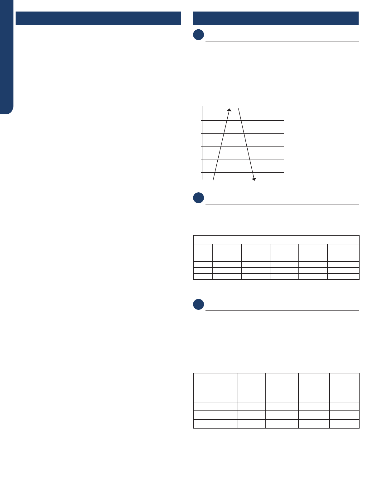
Compressor High Temperature
The compressor discharge pipe sensor (exhaust temp) senses
the temperature of the refrigerant exiting the compres-
sor. The sensed temperature received from the sensor by
the control circuitry will cause the compressor frequency to
increase or decrease. (see chart below). If a temperature of
>= 230°F is sensed for 20 seconds, an exhaust overheating
protection error code will be indicated at the outdoor unit.
Abnormal stop
Decreasing the frequency rapidly (1HZ/1 second)
TTC (°F)
230°F
212°F
209°F
199°F
194°F
Decreasing the frequency slowly (1HZ/10 seconds)
The frequency doesn’t change
Increasing the frequency (1HZ/10 seconds)
Increasing the frequency (1HZ/1 second)
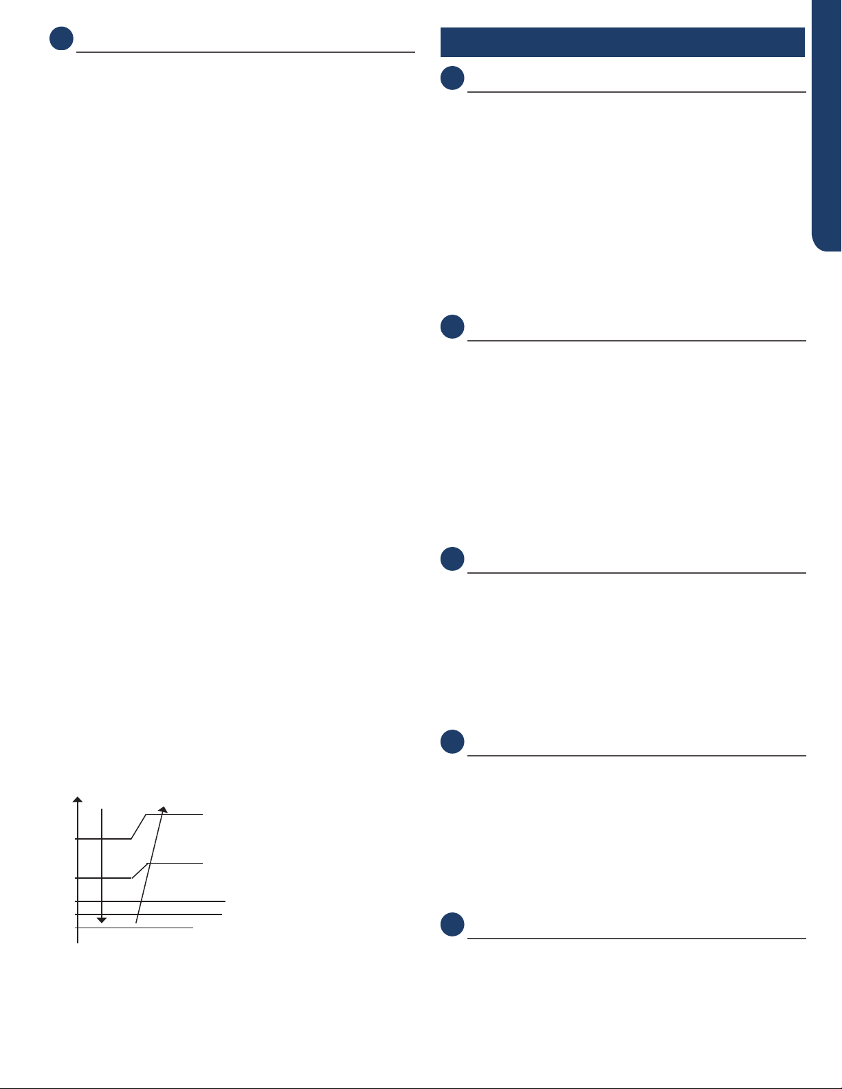
Overheating Protection for Indoor Unit
A sensor monitors coil temperature in both heating and cool-
ing modes, and causes the compressor to speed up, slow
down, or stop, according to the chart below.
Overheating Protection for Indoor Unit
Model Increasing
Slowly Holds Value Decreasing
Slowly
Decreasing
Rapidly
Compressor
Stops
24K 40°C/104°F 52°C/126°F 57°C/135°F 60°C/140°F 63°C/145°F
30K 40°C/104°F 52°C/126°F 57°C/135°F 60°C/140°F 63°C/145°F
36K 40°C/104°F 52°C/126°F 57°C/135°F 60°C/140°F 63°C/145°F
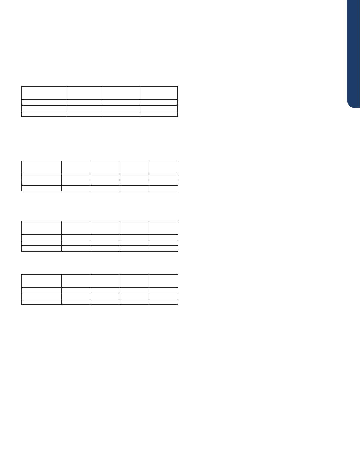
Compressor Over-Current Protection
If the current draw of the compressor at start-up is greater
than the values listed on the chart below for approximately
3 seconds, the compressor will stop. After 3 minutes the
compressor will restart. If the over-current condition occurs
3 times in 20 minutes, the system will lock-out, and a code
will be indicated at the outdoor unit. It will be necessary to
remove power to the system to reset the lock-out condition.
Model Holds
Value
Decrease
1Hz/10s
Decrease
1Hz/s
Over-
Current
Point
24K 16A 17A 18A 19A
30K 16A 17A 18A 19A
36K 16A 17A 18A 19A
SEQUENCE OF OPERATION PAGE 25
ENGLISH
Anti-Freeze Protection of the Indoor Coil
The temperature sensed by the coil sensor is used to deter-
mine at what speed the compressor is to run to avoid the coil
temperature being too cold.
Tpg_indoor: indoor unit pipe sensor temperature
When the outdoor ambient temperature is greater than 12°C,
Ts: outdoor unit Suction Line sensor temperature
• When Min(Tpg_indoor, Tpg_indoor+Ts)/2) < Tpg1, the
frequency of the compressor decreases at the rate of
1HZ/1 second.
• When Min(Tpg_indoor, Tpg_indoor+Ts)/2) < Tpg2, the
frequency of the compressor decreases at the rate of
1HZ/10 second.
• When Tpg_indoor begins to rise again, and Tpg2 ≤
Min(Tpg_indoor, Tpg_indoor+Ts)/2)≤ Tpg3, the frequency
of the compressor does not change.
• When Tpg3 < Min(Tpg_indoor, Tpg_indoor+Ts)/2) <Tpg4,
the frequency of the compressor increases at the rate of
1HZ/10 second.
Example: if Min(Tpg_indoor, Tpg_indoor+Ts)/2) ≤ 32°F
sustains for 2 minutes, the outdoor unit will stop and
indicate an underload malfunction code at the outdoor unit.
The compressor stops for a minimum of 3 minutes. When
Min(Tpg_ indoor , Tpg_indoor+Ts)/2)>Tpg4, the compressor
will restart.
When the outdoor ambient temperature is less than 12°C,
Ts: outdoor unit Suction Line sensor temperature
• When Min(Tpg_indoor) < Tpg1, the frequency of the
compressor decreases at the rate of 1HZ/1 second.
• When Min(Tpg_indoor) < Tpg2, the frequency of the
compressor decreases at the rate of 1HZ/10 second.
• When Tpg_indoor begins to rise again, and Tpg2 ≤
Min(Tpg_ indoor)≤ Tpg3, the frequency of the compressor
does not change.
• When Tpg3 < Min(Tpg_indoor) <Tpg4, the frequency of the
compressor increases at the rate of 1HZ/10 second.
Example: if Min(Tpg_indoor) ≤ 32°F sustains for 2 minutes, the
outdoor unit will stop and indicate an underload malfunction
code at the outdoor unit. The compressor stops for a
minimum of 3 minutes. When Min(Tpg_indoor >Tpg4, the
compressor will restart.
59°F // ice_temp_3+5
46°F // ice_temp_3+2
43°F
Decreasing slowly
Decreasing rapidly ice_temp_1
Stop
Keeping the frequency
Increasing slowly
32°F
37°F
41°F
43°F
48°F
Special Functions
Auto Restart
When this is enabled, the following functions will automatically
resumes after a power loss:
• ON/OFF State, Mode of Operation, Fan Speed,
Temperature Setpoint, Louver Swing settings.
• If there was a timer set or the system was in Sleep mode,
they will be canceled upon restart
Wired Controller:
• Auto Restart is Enabled by Default Wireless Controller:
• Enable: Press the Sleep button 10 times within 7 seconds.
You will hear 4 beeps as conrmation.
• Disable: Press the Sleep button 10 times within 7 seconds.
You will hear 2 beeps as conrmation.
Timed Defrost
Timed Defrost via Remote Controller (YR-HG)
(Same as dip switch 1 and 2 OFF):
Setting method:
1. Set to HEAT Mode.
2. Set to 30°C/86°F.
3. Set High Fan Speed.
4. Press Temperature + Button 10 times within 7 seconds.
5. Hear Unit will Beep 7 times to Conrm.
Cancel method:
Same process as Setting Method. Hear Unit Beep 5 times to
conrm of cancel function.
Demand Defrost
Force defrost via Remote Controller (YR-HG):
Setting method:
1. Set to HEAT Mode.
2. Set to 30°C/86°F.
3. Set High Fan Speed.
4. Press Health Button 10 times within 5 seconds.
5. Hear Unit will Beep 4 times to Conrm, System will enter
Force Defrost mode.
Indoor Temperature Display
This function will allow you to set the display to show either
the Ambient temperature or the setpoint.
Set temperature: Press the Light button 10 times within 5
second,Hear Unit will Beep 4 times to conrm.
Ambient temperature: Press the Light button 10 times within
5 second, Hear Unit will Beep 2 times to conrm.
Temperature Compensation
This function allows you the capability to adjust the tempera-
ture compensation oset of any indoor unit. The adjusted
value is programmed into the EEPROM.
Logic: The Actual Ambient Temperature = The Display Ambi-
ent Temperature + Temperature Compensation.

SEQUENCE OF OPERATION
PAGE 26
ENGLISH
Guide:
1. Apply power to the unit.
2. Set to Cooling Mode or Heating Mode.
3. Set the temperature to 75°F.
4. Press the SLEEP button 7 times within 5 seconds. Indoor
PCB will Beep 2 times to conrm.
5. 75°F will be the starting/reference point for the Tempera-
ture Compensation. Temperature Compensation can be
adjusted from -8° to +6° . Example: if you want to set the Tem-
perature Compensation value by 4°, then set the temperature
to 79°F.
6. Once the desired value has been selected, turn OFF the unit
via the YR-HG controller to save the compensation settings.
SmartHQ
The Bluetooth module will connect to the unit physically via
RJ45 (Service Port), and connect to the laptop via USB.
We can use it to achieve the following SmartHQ functions:
1. Software Updates
2. Real Time Sensor Readings / Load Control
3. View Alerts, Fault Data, Cycle History, Graphs
4. Automated Diagnostic Tests
5. Data Collection
Estar6.1
1. Energy Star self-inspection mode entry mode Use remote
control is to use remote control to enter arbitrary xed
frequency mode.
Fixed frequency mode:
• 1) Remote control refrigeration high wind, set to 60°F, press
the sleep button 4 times continuously within 7 seconds, the
inner machine will echo 5 times.
• 2) Remote control heating high wind, set to 86°F, press the
sleep button 4 times continuously within 7 seconds, the
inner machine echoes 5 times
2. Skip once Indoor unit (trigger controller includes remote
controller and wire controller):
The internal machine receives any Skip trigger signal:
• 1) Set the air supply mode and then change the current
wind speed;
• 2) If no trigger signal is received within 10 minutes after the
power-on enters the self-test mode, it will automatically
trigger and skip once; Symptom: The internal machine
displays JP and enters standby mode after 5S.
3. Permanently skip the Bypass function Indoor unit (trigger
controller includes remote controller and wire controller):
Internal machine receives Bypass signal:
• 1) Set dehumidication to 20 ° C (68 ° F) Symptom: The
internal machine displays BP and enters standby mode
after 5S.
After the product is installed and powered on for the rst
time, conrm e-star by following instructions.
Part 1:
Determine whether the e-star installation program is
required:
• 1. If CC is displayed alternately on the dual-8 display
boards of the indoor unit during the initial power-on, it
indicates that the machine can be used normally only after
conrmation of the e-STAR installation program.
• 2. If CC is not displayed alternately on the dual-8 display
boards of the indoor unit during the initial power-on,
the e-STAR installation program does not need to be
conrmed.
Part 2:
How to enter the self-test procedure:
When the indoor unit double 8 display board alternately
displays CC. Perform the following steps to enter the self-test
procedure.
Remote control Settings: In cooling or heating mode, set the
temperature to 25 degrees Celsius or 77 degrees Fahrenheit.
The machine will enter the following operation mode:
• A. When outdoor ambient temperature Tao > 75F, the air
supply mode of indoor unit at n1 stage (running “Start,
air supply, high wind”) runs for 3min; N2 stage; N3 stage
cooling mode (run “start up, cool, high wind, 16 degrees”)
Run for 15min N3 (blink once every 1 second).
• B. When the outdoor ring temperature is 14F≤Tao≤75F,
the air supply mode of the indoor unit at n1 stage (running
“Start, air supply, high air”) runs for 3min; N2 heating
mode (heating, high wind, 30 degrees) runs for 10min,
N2 (ashing once every 1 second), indoor to outdoor
send “start, heating, high wind, 30 degrees”; N3 stage
refrigeration mode (running “refrigeration, high wind, 16
degrees”) for 10min, N3 (ashing once every 1 second),
indoor to outdoor send “startup, refrigeration, high wind,
16 degrees”.
• C. When outdoor ambient temperature Tao < 14F, the
indoor unit air supply mode (running “start, air supply, high
wind”) at n1 stage runs for 3min; N2 stage heating mode
operation (running “heating, high wind, 30 degrees”) 15min
N2 (ashing once every second), no in N3 stage.
Note: Air supply mode, run for 3 minutes, display FN-N1
alternately on hanging panel; After the test is completed, the
internal machine panel shows PS, proving that the machine
has passed the self-test operation. The user can press any
button to exit the selftest and use the function normally.
Part 3:
How to skip the self-test procedure:
• 1. When CC is displayed on the internal machine, set by
remote control: press dehumidication mode when the
temperature is set to 20 degrees Celsius or 68 degrees
Fahrenheit. After setting, the hanging panel will display
bP, indicating that the machine has skipped the self-check
SEQUENCE OF OPERATION PAGE 27
ENGLISH
procedure and the user can use it normally.
• 2. If you have entered the self-check program, you need to
power o the machine, power on again, wait for the internal
machine CC display, then skip the self-check program
operation.
Part 4:
Test mode for manual measurements
• 1. Run refrigeration through NewFI according to the
following table parameters.
Full Parameters Compressor
Setting (Hz)
Fan Speed Set-
ting (RPM)
Exhaust Temp
Setting (°C)
AW24TL2HFA* 40 900 62
AW30TL2HFA* 59 900 70
AW36TL2HFA* 72 900 73
• 2. After the machine runs for 20 minutes, judge whether
the operating parameters of the machine are in the normal
range according to the parameters in the following table.
• A. The outer ring temperature is less than 10 degrees.
Check
Parameters
Suction
Temp.
Exhaust
Temp.
IDU Coil
Temp.
IDU Outlet
Temp.
AW24TL2HFA* <10°C 55°C~70°C 4°C~10°C 6°C~14°C
AW30TL2HFA* <10°C 65°C~75°C 4°C~10°C 6°C~14°C
AW36TL2HFA* <10°C 68°C~78°C 4°C~10°C 6°C~14°C
• B. The outer ring temperature is greater than 10 degrees
and less than 30 degrees.
Check
Parameters
Suction
Temp.
Exhaust
Temp.
IDU Coil
Temp.
IDU Outlet
Temp.
AW24TL2HFA* 2°C~10°C 55°C~70°C 8°C~14°C 10°C~15°C
AW30TL2HFA* 2°C~10°C 65°C~75°C 8°C~14°C 10°C~15°C
AW36TL2HFA* 2°C~10°C 68°C~78°C 8°C~14°C 10°C~15°C
• C. The outer ring temperature is greater than 30 degrees
Check
Parameters
Suction
Temp.
Exhaust
Temp.
IDU Coil
Temp.
IDU Outlet
Temp.
AW24TL2HFA* 4°C~15°C 55°C~70°C 8°C~18°C 10°C~20°C
AW30TL2HFA* 4°C~15°C 65°C~75°C 8°C~18°C 10°C~20°C
AW36TL2HFA* 4°C~15°C 68°C~78°C 8°C~18°C 10°C~20°C
• NOTE: The actual temperature parameters in the United
States are for reference only.
SYSTEM SPECIFICATIONS
PAGE 28
ENGLISH
SYSTEM SPECIFICATIONS
Model
Number
System TE* TE* TE*
Haier Brand Outdoor 1U24TL2HFA 1U3036TL2HFA 1U3036TL2HFA
Haier Brand Indoor AW24TL2HFA AW30TL2HFA AW36TL2HFA
Cooling
Rated Capacity Btu/hr 23,000 30,000 33,000
Capacity Range Btu/hr 6,000-25,000 7,000-32,000 8,000-36,000
23°F Cooling Without Wind Bae 18,400 24,000 26,400
-4°F Cooling with Wind Bae 23,000 30,000 33,000
-40°F Cooling w/dip switch
+ Wind Bae and Snow Hood 23,000 30,000 33,000
Rated Power Input W 1,900 3,000 3,900
SEER/EER 20.0/11.0 18.0/9.5 17.5/8.0
SEER2/EER2 19.1/11.0 18.0/9.5 17.5/8.0
Moisture Removal Pt./hr 3.60 5.20 7.30
Heating
Heating Capacity Range Btu/hr 6,000~28,000 7,000~34,000 8,000~39,000
Rated Heating Capacity 47°F Btu/hr 26,000 31,000 35,000
COP @ 5°F 2.00 1.75 1.75
Rated Heating Capacity 17°F Btu/hr 16,500 19,000 22,000
Max. Heating Capacity 17°F Btu/hr 19,000 22,000 25,000
Max. Heating Capacity 5°F Btu/hr 15,500 21,700 24,500
Max. Heating Capacity -4°F Btu/hr 12,900 18,600 21,000
H11, Low Capacity @ 47°F 6,400 6,800 6,800
Rated Power Input W 2,200 2,900 3,600
HSPF 10.0 9.5 9.5
HSPF2 (IV) 8.6 8.5 8.5
Operating
Range
Cooling w/o Wind Bae °F(°C) 23~115°F (-5~46°C) 23~115°F (-5~46°C) 23~115°F (-5~46°C)
Cooling w/Wind Bae °F(°C) -4~115°F (-20~46°C) -4~115°F (-20~46°C) -4~115°F (-20~46°C)
Cooling w/dip switch + Wind Bae and
Snow Hood °F(°C) -40~115°F (-40~46°C) -40~115°F (-40~46°C) -40~115°F (-40~46°C)
Heating °F (°C) -4~75°F (-20-24°C) -4~75°F (-20-24°C) -4~75°F (-20-24°C)
Power Supply Voltage - Cycle - Phase (V/Hz/-) 208/230 - 60 - 1 208/230 - 60 - 1 208/230 - 60 - 1
Outdoor Unit
Compressor Type DC Inverter Driven Rotary DC Inverter Driven Rotary DC Inverter Driven Rotary
Maximum Fuse Size A 30 30 30
Minimum Circuit Amp A 27 27 27
Outdoor Noise Level dB 68 68 68
Dimension: H x W x D in (mm) 30 (762) x 36 1/4 (920) x 15 1/8 (385) 30 (762) x 36 1/4 (920) x 15 1/8 (385) 30 (762) x 36 1/4 (920) x 15 1/8 (385)
Weight Ship/Net - lbs (kg) 165/145 (75/65.5) 165/145 (75/65.5) 165/145 (75/65.5)
Indoor Unit
Fan Speed Stages 5 5 5
Indoor Motor Speed
(Turbo/High/Med/Low/Quiet) 1150/1100/950/800/700 1200/1150/975/800/700 1250/1200/1000/800/700
Airow CFM
(Turbo/High/Med/Low/Quiet) 810/750/635/520/440 875/810/660/520/440 920/875/700/520/440
Indoor Sound Level dB
(Turbo/High/Med/Low/Quiet) 62/59/52/48/42 62/59/52/48/42 62/59/52/48/42
Dimension: H x W x D in (mm) 14.4 (365) x 51.8 (1316) x 10.8 (275) 14.4 (365) x 51.8 (1316) x 10.8 (275) 14.4 (365) x 51.8 (1316) x 10.8 (275)
Weight Ship/Net - lbs (kg) 56.2/46.3(25.5/21) 56.2/46.3(25.5/21) 56.2/46.3(25.5/21)
Refrigerant
Lines
Connections Flare Flare Flare
Liquid O.D. / Suction O.D. in. 3/8" / 5/8” 3/8" / 5/8” 3/8" / 5/8”
Factory Charge Oz 84.7 84.7 84.7
Maximum Line Length Ft / m 165/50 165/50 165/50
Maximum Height Ft / m 100/30 100/30 100/30
Accessories
Ships with Remote Controller YR-HG (Haier or GE logo) YR-HG (Haier or GE logo) YR-HG (Haier or GE logo)
Compatible with Remote Controller Cool Only (No logo) Cool Only (No logo) Cool Only (No logo)
Compatible with Wired Controller YR-E16B, QACT17A*, ACT17CWA* YR-E16B, QACT17A*, ACT17CWA* YR-E16B, QACT17A*, ACT17CWA*
WiFi/App Built-In Built-In Built-In
Wind Bae UAWB46A UAWB46A UAWB46A
Snow Hood UAWB82A UAWB82A UAWB82A
Important
Features
Self-Clean Indoor and Outdoor via App Indoor and Outdoor via App Indoor and Outdoor via App
Data Connection RJ45 Standard / GE3 RJ45 Standard / GE3 RJ45 Standard / GE3
Features and
Benets
Dual System Auto Switch Yes, via Central Controller Yes, via Central Controller Yes, via Central Controller
Cool Only Lock Yes, via Indoor DIP Switch Yes, via Indoor DIP Switch Yes, via Indoor DIP Switch
*REQUIRES ADAPTER WK-B

ERROR CODES AND TROUBLESHOOTING PAGE 29
ENGLISH
Error Codes and Troubleshooting
Table of Contents
Check This First Outdoor Unit .......................................................................................................................................... 30
Check This First Indoor Unit ............................................................................................................................................. 31
Indoor/Outdoor Error Codes ............................................................................................................................................ 33
F1/LED1: 2 Flash ........................................................................................................................................................................... 34
F2/LED1: 24 Flash ......................................................................................................................................................................... 36
F3/LED1: 4 Flash ........................................................................................................................................................................... 38
F4/LED1: 8 Flash ........................................................................................................................................................................... 40
F6/LED1: 12 Flash ......................................................................................................................................................................... 42
F7/LED1: 11 Flash ......................................................................................................................................................................... 42
F21/LED1: 10 Flash ....................................................................................................................................................................... 42
F25/LED1: 13 Flash ....................................................................................................................................................................... 42
E1/LED1: No Flash ........................................................................................................................................................................ 42
E2/LED1: No Flash ........................................................................................................................................................................ 42
F8/LED1: 9 Flash ........................................................................................................................................................................... 45
F11/LED1: 18 Flash ...................................................................................................................................................................... 47
F12/LED1: 1 Flash ......................................................................................................................................................................... 49
E5/LED1: 22 Flash ......................................................................................................................................................................... 50
E7/LED1: 15 Flash ........................................................................................................................................................................ 53
Indoor Error Code
E14 ................................................................................................................................................................................................. 57
Checking System Components ........................................................................................................................................ 60
Checking Outdoor Unit Components ............................................................................................................................... 60
CheckingtheOutdoorUnitSensors .............................................................................................................................................60
CheckingtheReversingValveCoil ................................................................................................................................................60
CheckingtheDCFanMotor ...........................................................................................................................................................60
CheckingtheEEVCoil .................................................................................................................................................................... 60
CheckingtheCompressorWindings ..........................................................................................................................................................60
Checking Indoor Unit Components ................................................................................................................................... 61
CheckingtheIndoorUnitSensors .................................................................................................................................................61
CheckingtheUp/DownStepperMotor ........................................................................................................................................61
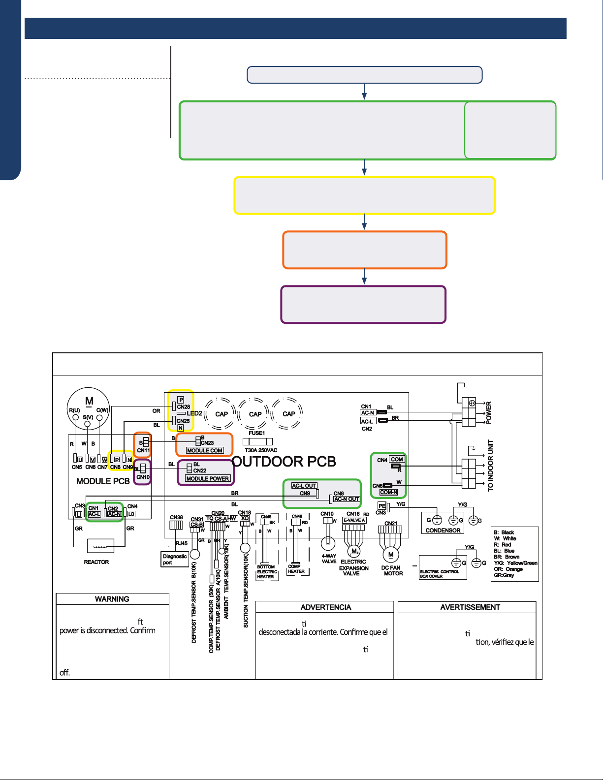
ERROR CODES AND TROUBLESHOOTING
PAGE 30
ENGLISH
Check This First
Outdoor Unit
Models:
1U24TL2HFA
1U3036TL2HFA
ASH124TRDFA
ASH3036TRDFA
Line voltage available at:
1. TERMINAL STRIP - 1(N) & 2 (L)
2. AC-L & AC-N at the PCB - CN2 & CN1
3. AC-L OUT & AC-N OUT at the PCB - CN8 & CN9
4. AC-L & AC-N at the IPM - CN1 & CN2 (24K/30K/36K)
310+ VDC available at:
1. P & N at the IPM - CN8 & CN9 (24K/30K/36K)
2. P & N at the PCB - CN24 & CN26
Module power 5-G-15 VDC available at:
1. CN23 at the PCB
2. CN11 at the IPM
Module COM 5-G-15 VDC available at:
1. CN22 AT THE PCB
2. CN10 AT THE IPM
• 1 (N) and 3 (C): 0-80
VAC uctuating
• 2 (L) and 3 (C):
0-140 VAC
uctuating
Wiring Diagram Reference
OUTDOOR UNIT WIRING DIAGRAM
COMPRESSOR
●
●
B
Y/G
123(C)
N
L
BL
BR
BR
BR
BL
Y/G
Y/G
0011520512
Electrical Shock Hazard
Capacitor retains charge a er
voltage at capacitor has dissipated
(<10V DC) with hand held voltmeter
before servicing. LED2 light
between CN24 and CN26 should be
Riesgo de Descarga Eléctrica
El capacitor re ene carga una vez
voltaje del capacitor se haya disipado (<10V
DC) apoyando la mano sobre el vol metro
antes de realizar el servicio técnico. La luz
LED2 que se encuentra entre CN24 y CN26
deberá estar apagada.
Risque de choc électrique
Le condensateur conserve sa charge après la
coupure de l’alimenta on électrique. Avant
de procéder à une répara
courant au condensateur s’est dissipé
(<10 VCC) à l’aide d’un voltmètre manuel. Le
voyant LED2 entre CN24 et CN26 doit être
éteint.
Conditions Needed for Basic Operation
3-minutes of time delay from the call for heating or cooling
Error Codes and Troubleshooting
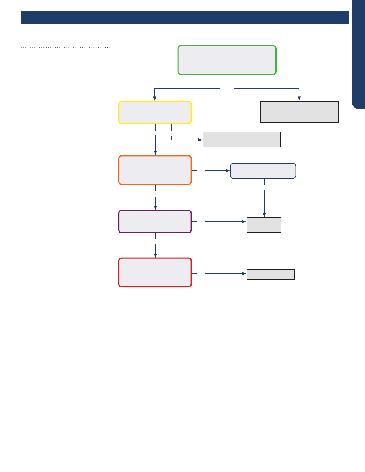
ERROR CODES AND TROUBLESHOOTING PAGE 31
ENGLISH
Error Codes and Troubleshooting
Yes
Yes
Yes
Yes
No
No
No
Yes No
No
Determine source of lost
power from OD unit or phase
imbalance from building power
Determine source of lost
communication from OD unit
Replace
PCB
Replace sensor
There is 230 VAC (+/- 10%) at terminal
strip connections 1(N) and 2(L), and
no more than a 2% deviation between
each leg and ground?
There is a pulsing 0 to 80
VAC between terminal strip
connections 1(N) and 3(C)?
There is 230 VAC at
terminals CN17 and CN21
on the PCB, and the LED
ashes 3 times per second
There is 5 VDC at CN6
across both sets of black
sensor wires?
The sensor resistance is
within 3% of the value listed
in the Service Manual sensor
resistance table?
Wiring and connections
are in good condition?
Check This First
Indoor Unit
Models:
AW24TL2HFA
AW30TL2HFA
AW36TL2HFA
ASYW24TRDFA
ASYW30TRDFA
ASYW36TRDFA
See following page for
wiring diagram, relevant
color-coded test
positions, and sensor
resistance values.
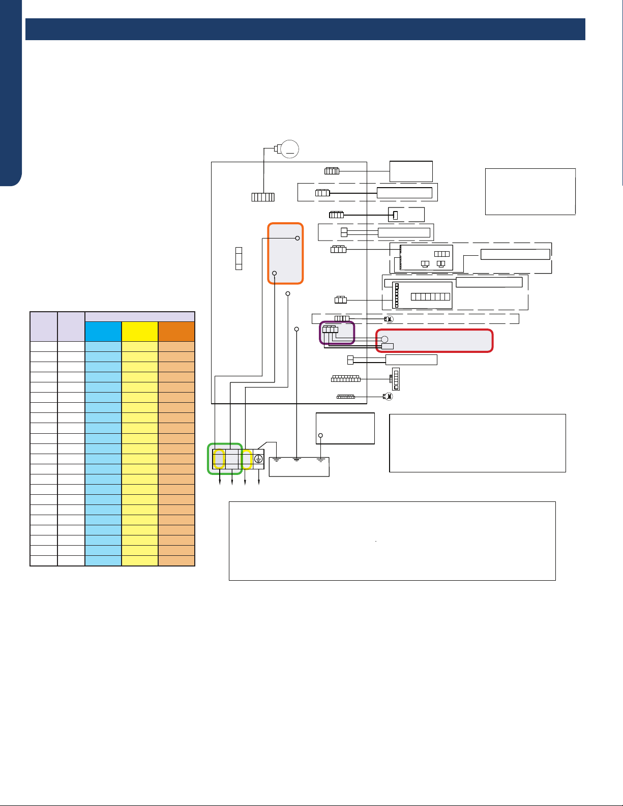
ERROR CODES AND TROUBLESHOOTING
PAGE 32
ENGLISH
Error Codes and Troubleshooting
Check This First - Indoor Unit
Wiring Diagram Reference
Sensor Resistance Table
°F °C
Normal (KΩ
10K
SENSORS
23K
SENSORS
50K
SENSORS
-0.4 -18 75.44 235.90 5494.21
5.0 -15 64.30 196.61 4558.19
10.4 -12 54.99 164.40 3795.39
14.0 -10 49.62 146.15 3365.73
21.2 -6 40.58 115.95 2658.81
24.8 -4 36.77 103.46 2368.32
32.0 0 30.30 82.69 1887.00
35.6 2 27.55 74.07 1687.81
41.0 5 23.95 62.94 1431.28
44.6 7 21.84 56.57 1284.36
50.0 10 19.06 48.31 1094.32
55.4 13 16.68 41.40 934.94
59.0 15 15.28 37.41 843.05
64.4 18 13.42 32.22 723.41
69.8 21 11.81 27.83 622.32
75.2 24 10.42 24.11 536.65
77.0 25 10.00 23.00 511.08
80.6 27 9.21 20.95 464.05
86.0 30 8.16 18.25 402.24
89.6 32 7.54 16.67 366.13
95.0 35 6.70 14.59 318.52
100.4 38 5.97 12.79 277.70
R:Red
●
W:White
Y:Yellow
Y/G:Yellow/Green
B:Black
BR:Brown
BL:Blue
PIPING TEMP.SENSOR(10K)
●
AMBIENT TEMP.SENSOR(10K)
POWER BUTTON
Notes:
1.The dotted parts are optiona
●
l.
2.The two pins of CN51 should be shorted,
when the J6 is cuted off.
M
FUSE1
CN7
T3.15A/250VAC
TO OUTDOOR UNIT
1(N) (C)
3
(L)
2
WB
Y/G
GND
CN6
R
(L)
CN21
N
COMM
CN51
CN9
CN17
CN23'
CN35
CN34
ROOM CARD
CN5
DC FAN MOTOR
CN11'
DISPLAY BOARD
Model selection:
●
24K model-23 code - BM1 - 1
●
off 2 off
24K model-26 code - BM1 - 1 off 2 on
WIRED CONTROLLER
UP-DOWN STEPMOTOR
LEFT & RIGHT STEPMOTOR
WIFI
CN14
Notes:Before replacing the board,it
is necessary to ensure that the
machine is matched with the board
code
CN56 HUMAN SENSOR
CN38
CN27'
Y/G
GND
WK-B
EVAPORATOR
ELECTRIC
CONTROL BOX
COVER
GND
Y/G
RJ45
Diagnostic
port
CN5
CN1
CN2
SW1
OFF OFF OFF OFF
CN3 CN4
CN2
CN6
CN4
CN3
CENTRALIZED CONTROLLER
SW2
OFF OFF OFF OF F OFF OFF OFF OFF
CN36
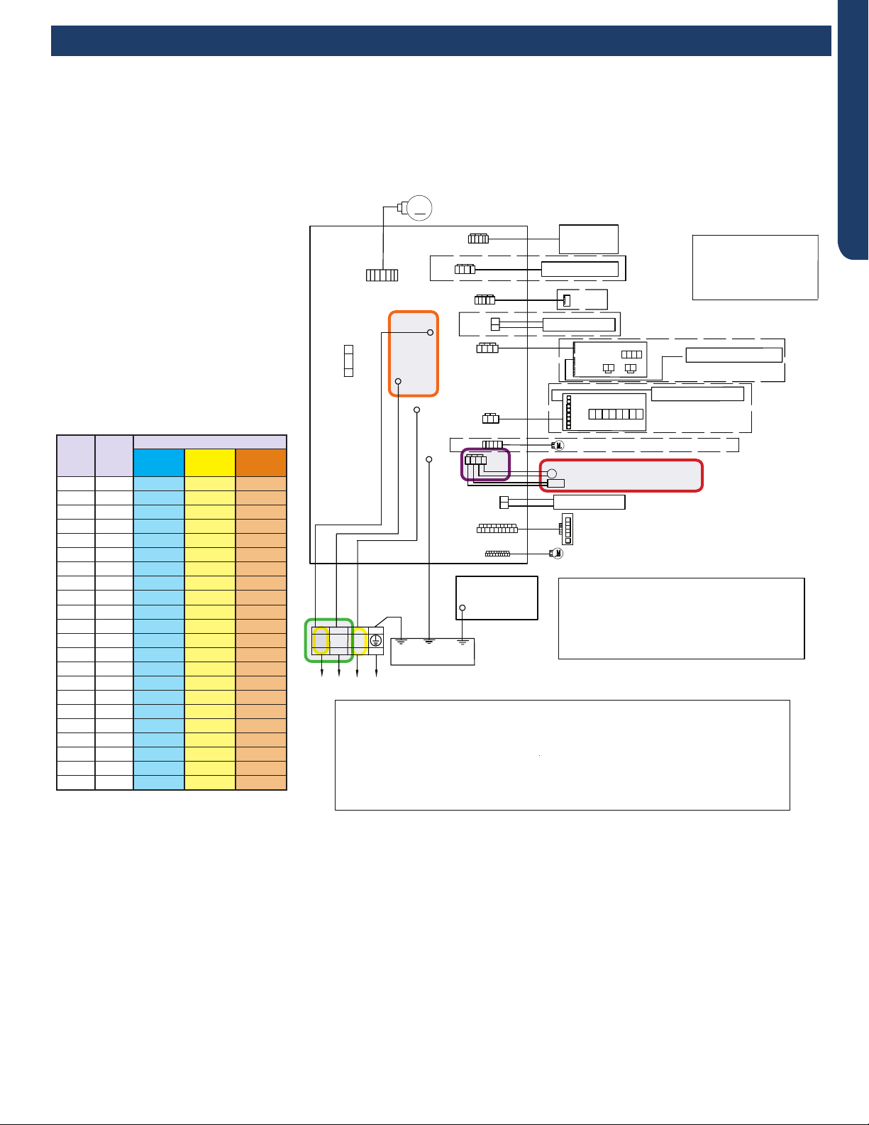
ERROR CODES AND TROUBLESHOOTING PAGE 33
ENGLISH
Error Codes and Troubleshooting
Check This First - Indoor Unit
Wiring Diagram Reference
Sensor Resistance Table
°F °C
Normal (KΩ
10K
SENSORS
23K
SENSORS
50K
SENSORS
-0.4 -18 75.44 235.90 5494.21
5.0 -15 64.30 196.61 4558.19
10.4 -12 54.99 164.40 3795.39
14.0 -10 49.62 146.15 3365.73
21.2 -6 40.58 115.95 2658.81
24.8 -4 36.77 103.46 2368.32
32.0 0 30.30 82.69 1887.00
35.6 2 27.55 74.07 1687.81
41.0 5 23.95 62.94 1431.28
44.6 7 21.84 56.57 1284.36
50.0 10 19.06 48.31 1094.32
55.4 13 16.68 41.40 934.94
59.0 15 15.28 37.41 843.05
64.4 18 13.42 32.22 723.41
69.8 21 11.81 27.83 622.32
75.2 24 10.42 24.11 536.65
77.0 25 10.00 23.00 511.08
80.6 27 9.21 20.95 464.05
86.0 30 8.16 18.25 402.24
89.6 32 7.54 16.67 366.13
95.0 35 6.70 14.59 318.52
100.4 38 5.97 12.79 277.70
R:Red
●
W:White
Y:Yellow
Y/G:Yellow/Green
B:Black
BR:Brown
BL:Blue
PIPING TEMP.SENSOR(10K)
●
AMBIENT TEMP.SENSOR(10K)
POWER BUTTON
Notes:
1.The dotted parts are optiona
●
l.
2.The two pins of CN51 should be shorted,
when the J6 is cuted off.
M
FUSE1
CN7
T3.15A/250VAC
TO OUTDOOR UNIT
1(N) (C)
3
(L)
2
WB
Y/G
GND
CN6
R
(L)
CN21
N
COMM
CN51
CN9
CN17
CN23'
CN35
CN34
ROOM CARD
CN5
DC FAN MOTOR
CN11'
DISPLAY BOARD
Model selection:
WIRED CONTROLLER
UP-DOWN STEPMOTOR
LEFT & RIGHT STEPMOTOR
WIFI
CN14
Notes:Before replacing the board,it
is necessary to ensure that the
machine is matched with the board
code
CN56 HUMAN SENSOR
CN38
CN27'
Y/G
GND
WK-B
EVAPORATOR
ELECTRIC
CONTROL BOX
COVER
GND
Y/G
RJ45
Diagnostic
port
CN5
CN1
CN2
SW1
OFF OFF OFF OFF
CN3 CN4
CN2
CN6
CN4
CN3
CENTRALIZED CONTROLLER
SW2
OFF OFF OFF OF F OFF OFF OFF OFF
CN36
model-23 code - BM1 - 1 off 2 off
model-26 code - BM1 - 1 off 2 on
2 off
30K
30K
36K
36K
model-33 code - BM1 - 1 on
model-35 code - BM1 - 1 on 2 on
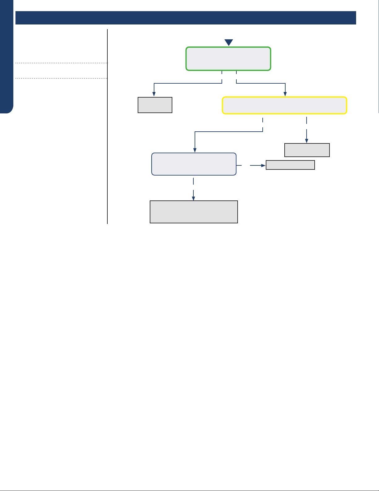
ERROR CODES AND TROUBLESHOOTING
PAGE 34
ENGLISH
Error Codes and Troubleshooting
Error Code (Indoor/Outdoor)
F1/LED1: 2 Flash
IPM Power Module Fail
(IPM power module protection)
Completethe“CheckThisFirst”Flow
Chartbeforecontinuing.
Models:
AW24TL2HFA
AW30TL2HFA
AW36TL2HFA
ASYW24TRDFA
ASYW30TRDFA
ASYW36TRDFA
1U24TL2HFA
1U3036TL2HFA
ASH124TRDFA
ASH3036TRDFA
Yes
No
No
Yes
Yes No
Start
Cycle power to the outdoor
unit. Does LED1 ash 2 times
before the compressor starts?
Compressor runs for 10 min.
and stops with LED in center of
PCB ashing 2 times?
DC voltage from P-U, P-V, P-W is 150-160VDC,
DC voltage from N-U, N-V, N-W 150-160VDC?
Replace
IPM
Replace IPM
Normal operation
Check coil cleanliness,
EEV operation, compressor
windings, and refrigerant charge
See following page
for wiring diagram,
relevant color-coded
test positions, and EEV
resistance values.
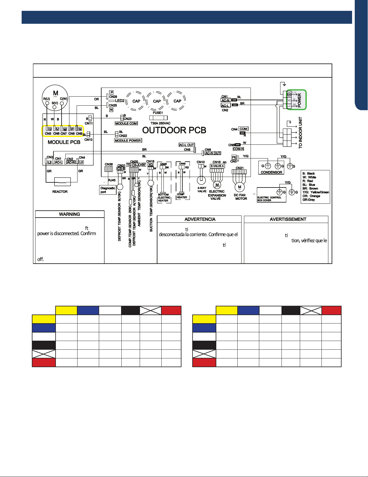
ERROR CODES AND TROUBLESHOOTING PAGE 35
ENGLISH
OUTDOOR UNIT WIRING DIAGRAM
COMPRESSOR
●
●
B
Y/G
123(C)
N
L
BL
BR
BR
BR
BL
Y/G
Y/G
0011520512
Electrical Shock Hazard
Capacitor retains charge a er
voltage at capacitor has dissipated
(<10V DC) with hand held voltmeter
before servicing. LED2 light
between CN24 and CN26 should be
Riesgo de Descarga Eléctrica
El capacitor re ene carga una vez
voltaje del capacitor se haya disipado (<10V
DC) apoyando la mano sobre el vol metro
antes de realizar el servicio técnico. La luz
LED2 que se encuentra entre CN24 y CN26
deberá estar apagada.
Risque de choc électrique
Le condensateur conserve sa charge après la
coupure de l’alimenta on électrique. Avant
de procéder à une répara
courant au condensateur s’est dissipé
(<10 VCC) à l’aide d’un voltmètre manuel. Le
voyant LED2 entre CN24 et CN26 doit être
éteint.
Error Codes and Troubleshooting
Error Code: F1/LED1: 2 Flash
Wiring Diagram Reference
EEV Resistance Values
EEV (6-pin, 6 wire)
Yellow Blue White Black Red
Yellow - OL 92 Ω OL 46 Ω OL
Blue - - OL 92 Ω OL 46 Ω
White - - - OL 46 Ω OL
Black - - - - OL 46 Ω
- - - - - OL
Red - - - - - -
EEV (6-pin, 5 wire)
Yellow Blue White Black Red
Yellow - 92 Ω 92 Ω 92 Ω - 46 Ω
Blue - - 92 Ω 92 Ω - 46 Ω
White - - - 92 Ω - 46 Ω
Black - - - - - 46 Ω
- - - - - -
Red - - - - - -
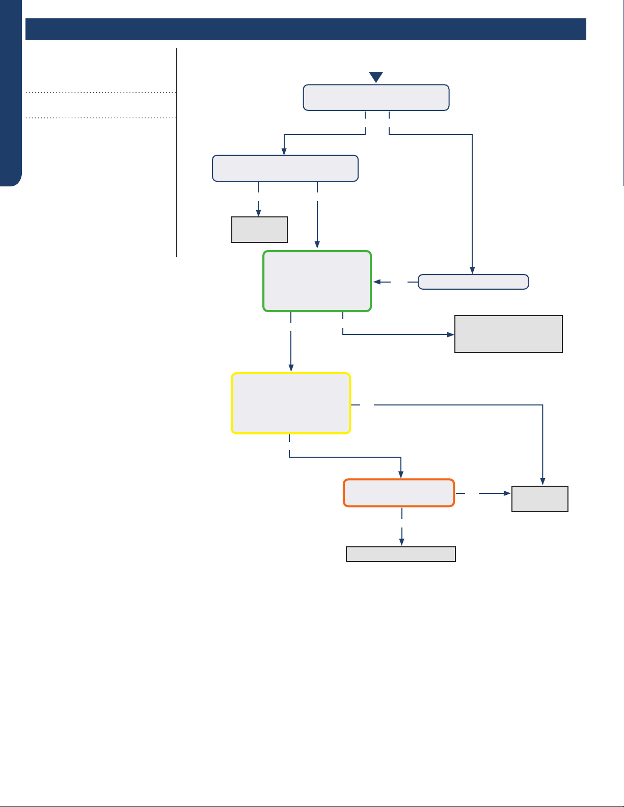
ERROR CODES AND TROUBLESHOOTING
PAGE 36
ENGLISH
Error Codes and Troubleshooting
Yes
Yes No
Yes
No
No
Yes
Yes
No
No
Yes
Continue to monitor;
the system is starting
under an abnormal load
Replace
IPM
Replace
IPM
Check refrigerant charge
Start
The set temperature is 5°F max.
from the room temperature?
Does the error code display
before the compressor starts?
With power o for
5 min and back on,
compressor exceeds
over-current point in
Service Manual?
There is pulsing 50-200
VAC at compressor
terminals U, V, and W , read
from the terminal solder
points on the IPM?
There is 264-373 VDC at
P and N on the IPM?
Change set temperature
Error Code (Indoor/Outdoor)
F2/LED1: 24 Flash
Overcurrent of the Compressor
Completethe“CheckThisFirst”Flow
Chartbeforecontinuing.
Models:
AW24TL2HFA
AW30TL2HFA
AW36TL2HFA
ASYW24TRDFA
ASYW30TRDFA
ASYW36TRDFA
1U24TL2HFA
1U3036TL2HFA
ASH124TRDFA
ASH3036TRDFA
See following page
for wiring diagram and
relevant color-coded
test positions.
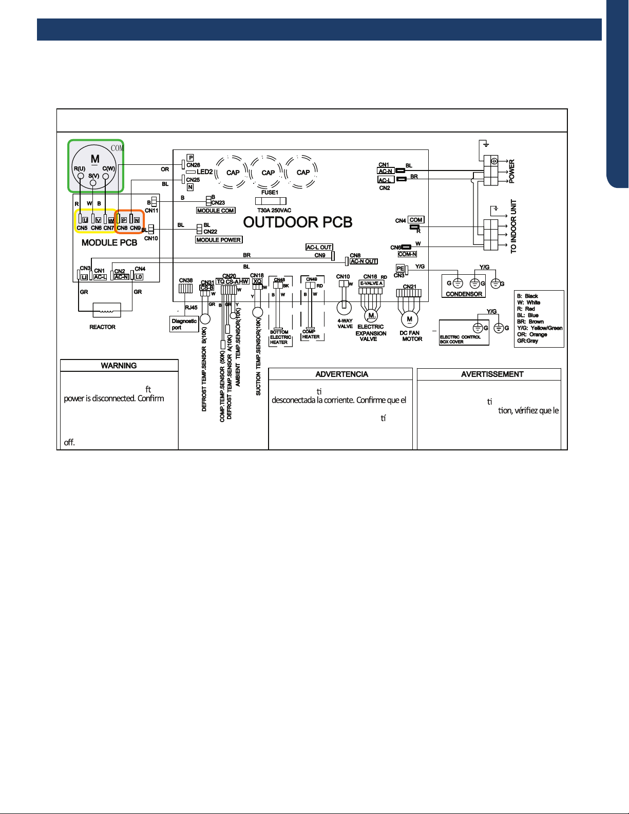
ERROR CODES AND TROUBLESHOOTING PAGE 37
ENGLISH
OUTDOOR UNIT WIRING DIAGRAM
COMPRESSOR
●
●
B
Y/G
123(C)
N
L
BL
BR
BR
BR
BL
Y/G
Y/G
0011520512
Electrical Shock Hazard
Capacitor retains charge a er
voltage at capacitor has dissipated
(<10V DC) with hand held voltmeter
before servicing. LED2 light
between CN24 and CN26 should be
Riesgo de Descarga Eléctrica
El capacitor re ene carga una vez
voltaje del capacitor se haya disipado (<10V
DC) apoyando la mano sobre el vol metro
antes de realizar el servicio técnico. La luz
LED2 que se encuentra entre CN24 y CN26
deberá estar apagada.
Risque de choc électrique
Le condensateur conserve sa charge après la
coupure de l’alimenta on électrique. Avant
de procéder à une répara
courant au condensateur s’est dissipé
(<10 VCC) à l’aide d’un voltmètre manuel. Le
voyant LED2 entre CN24 et CN26 doit être
éteint.
Error Codes and Troubleshooting
Error Code: F2/LED1: 24 Flash
Wiring Diagram Reference
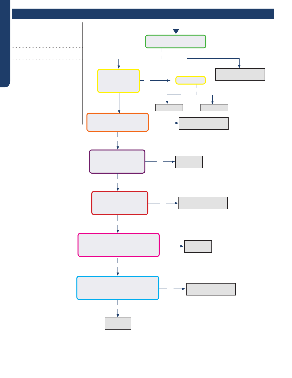
ERROR CODES AND TROUBLESHOOTING
PAGE 38
ENGLISH
Error Codes and Troubleshooting
Yes
Yes
Yes
Start
No
No
No
No
No
Line voltage at AC-L & AC-N
on the PCB (CN2 & CN1)?
Line voltage at AC-L & AC-N
on the IPM (24K/30K/36K
CN1 & CN2)?
Module Power voltage -
CN22 on the PCB:
Across pins 1 & 2 = 5VDC
Across pins 2 & 3 = 15VDC?
Module Power voltage -
CN10 on the IPM
Across pins 1 & 2 = 5VDC
Across pins 2 & 3 = 15VDC?
Module Com voltage - CN23 on the PCB
With a call for Heating or Cooling,
Across pins 1 & 2 = 5VDC
Across pins 2 & 3 = 15VDC ?
Module Com voltage - CN11 on the IPM
With a call for Heating or Cooling,
Across pins 1 & 2 = 5VDC
Across pins 2 & 3 = 15VDC?
Yes
Yes
Yes
No
Yes No
Yes No
Check incoming power
from building
Replace PCB
Replace
PCB
Replace fuse
Replace CN9 and CN10
wiring harness
Replace module power
wiring harness
Replace
PCB
Replace
IPM
Fuse 1 is OK?
Line voltage at
AC-L OUT & AC-N
OUT on the PCB
(CN8 & CN9)?
Error Code (Indoor/Outdoor)
F3/LED1: 4 Flash
Communication Fault Between IPM and
Outdoor PCB
Completethe“CheckThisFirst”Flow
Chartbeforecontinuing.
Models:
AW24TL2HFA
AW30TL2HFA
AW36TL2HFA
ASYW24TRDFA
ASYW30TRDFA
ASYW36TRDFA
1U24TL2HFA
1U3036TL2HFA
ASH124TRDFA
ASH3036TRDFA
Replace module COM
wiring harness
See following page
for wiring diagram and
relevant color-coded
test positions.
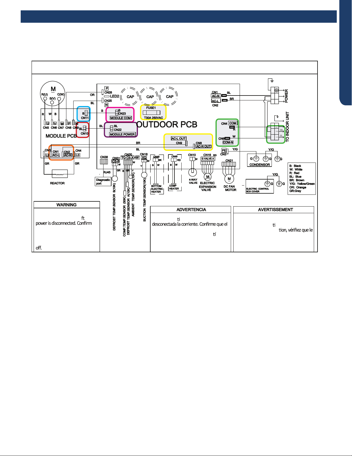
ERROR CODES AND TROUBLESHOOTING PAGE 39
ENGLISH
OUTDOOR UNIT WIRING DIAGRAM
COMPRESSOR
●
●
B
Y/G
123(C)
N
L
BL
BR
BR
BR
BL
Y/G
Y/G
0011520512
Electrical Shock Hazard
Capacitor retains charge a er
voltage at capacitor has dissipated
(<10V DC) with hand held voltmeter
before servicing. LED2 light
between CN24 and CN26 should be
Riesgo de Descarga Eléctrica
El capacitor re ene carga una vez
voltaje del capacitor se haya disipado (<10V
DC) apoyando la mano sobre el vol metro
antes de realizar el servicio técnico. La luz
LED2 que se encuentra entre CN24 y CN26
deberá estar apagada.
Risque de choc électrique
Le condensateur conserve sa charge après la
coupure de l’alimenta on électrique. Avant
de procéder à une répara
courant au condensateur s’est dissipé
(<10 VCC) à l’aide d’un voltmètre manuel. Le
voyant LED2 entre CN24 et CN26 doit être
éteint.
Error Codes and Troubleshooting
Error Code: F3/LED1: 4 Flash
Wiring Diagram Reference
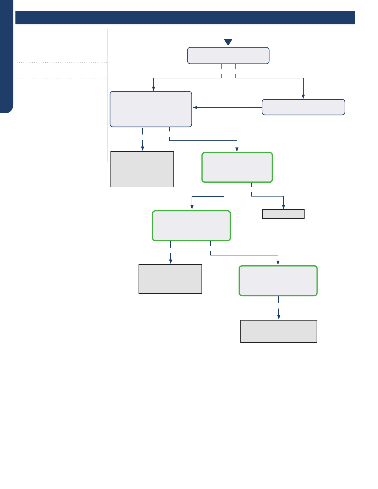
ERROR CODES AND TROUBLESHOOTING
PAGE 40
ENGLISH
Error Codes and Troubleshooting
Yes
Yes
Yes
Yes No
No
No
Yes No
Recover refrigerant,
remove moisture and
air from system, charge
with fresh refrigerant
to nameplate amount
Check for a fan motor
issue, restricted line
set or EEV, or lack of
refrigerant
Check for a plugged coil or
lter, a high load, or incorrect
refrigerant charge
Replace sensor
The discharge line temperature
is below 230°F/110°C?
The discharge sensor
ohmreading matches the
resistance table in the
Service Manual?
With system on, the
discharge sensor climbs to
230°F within a short time, and
the compressor stops?
With system on, the
discharge sensor climbs to
230°F after several minutes,
and the compressor stops?
Turn power o for 20 min. to
allow the discharge line to cool
Refrigerant static test (system
o for 20 min.) indicates
head pressure converted to
temperature is higher than
ambient?
Error Code (Indoor/Outdoor)
F4/LED1: 8 Flash
Overheat Protection For Discharge
Temperature
Completethe“CheckThisFirst”Flow
Chartbeforecontinuing.
Models:
AW24TL2HFA
AW30TL2HFA
AW36TL2HFA
ASYW24TRDFA
ASYW30TRDFA
ASYW36TRDFA
1U24TL2HFA
1U3036TL2HFA
ASH124TRDFA
ASH3036TRDFA
Start
See following page
for wiring diagram,
relevant color-coded
test positions, and EEV
resistance values.

ERROR CODES AND TROUBLESHOOTING PAGE 41
ENGLISH
OUTDOOR UNIT WIRING DIAGRAM
COMPRESSOR
●
●
B
Y/G
123(C)
N
L
BL
BR
BR
BR
BL
Y/G
Y/G
0011520512
Electrical Shock Hazard
Capacitor retains charge a er
voltage at capacitor has dissipated
(<10V DC) with hand held voltmeter
before servicing. LED2 light
between CN24 and CN26 should be
Riesgo de Descarga Eléctrica
El capacitor re ene carga una vez
voltaje del capacitor se haya disipado (<10V
DC) apoyando la mano sobre el vol metro
antes de realizar el servicio técnico. La luz
LED2 que se encuentra entre CN24 y CN26
deberá estar apagada.
Risque de choc électrique
Le condensateur conserve sa charge après la
coupure de l’alimenta on électrique. Avant
de procéder à une répara
courant au condensateur s’est dissipé
(<10 VCC) à l’aide d’un voltmètre manuel. Le
voyant LED2 entre CN24 et CN26 doit être
éteint.
Error Codes and Troubleshooting
Error Code: F4/LED1: 8 Flash
Wiring Diagram Reference
EEV Resistance Values
EEV (6-pin, 6 wire)
Yellow Blue White Black Red
Yellow - OL 92 Ω OL 46 Ω OL
Blue - - OL 92 Ω OL 46 Ω
White - - - OL 46 Ω OL
Black - - - - OL 46 Ω
- - - - - OL
Red - - - - - -
EEV (6-pin, 5 wire)
Yellow Blue White Black Red
Yellow - 92 Ω 92 Ω 92 Ω - 46 Ω
Blue - - 92 Ω 92 Ω - 46 Ω
White - - - 92 Ω - 46 Ω
Black - - - - - 46 Ω
- - - - - -
Red - - - - - -
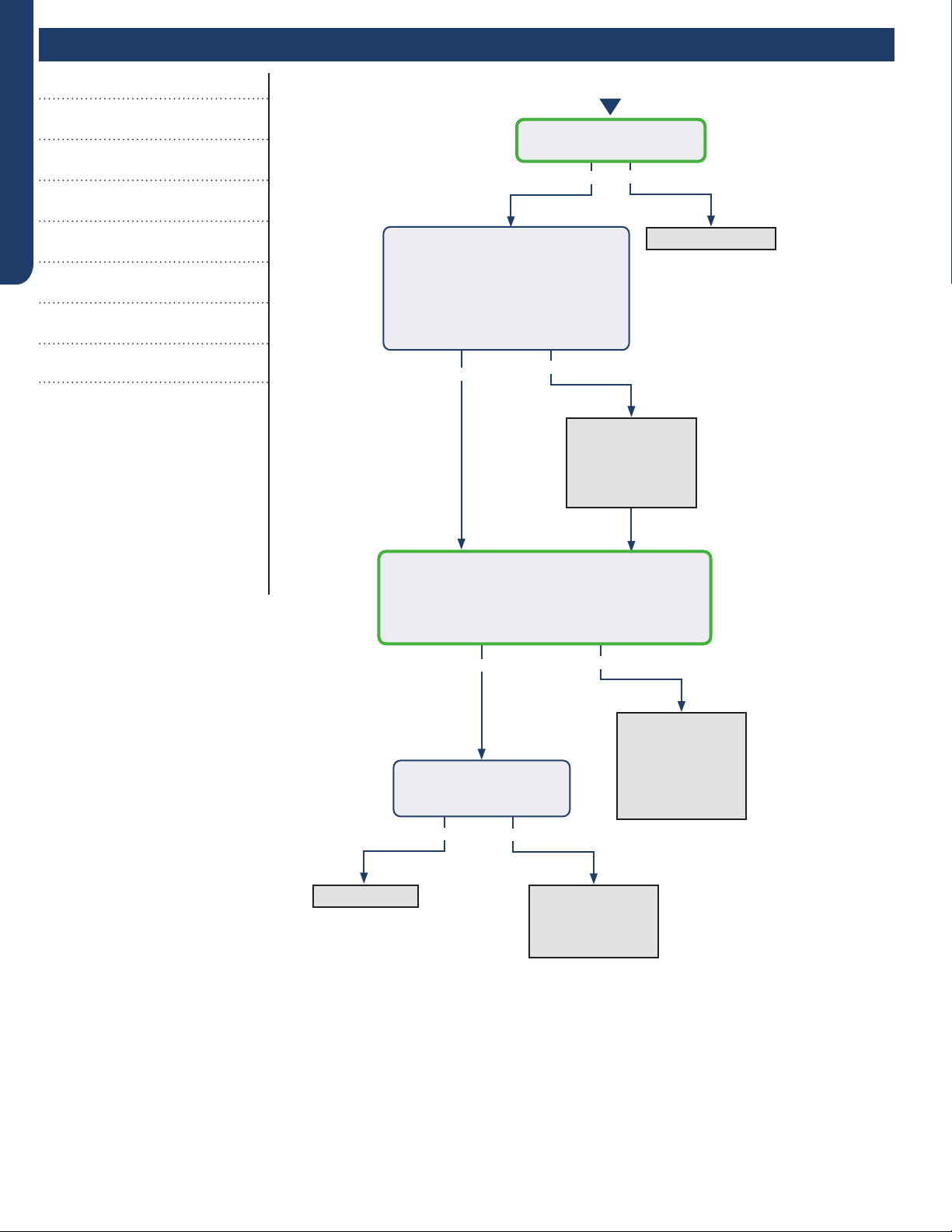
ERROR CODES AND TROUBLESHOOTING
PAGE 42
ENGLISH
Error Codes and Troubleshooting
See following page for
wiring diagram, relevant
color-coded test
positions, and sensor
resistance values.
Error Codes (Indoor/Outdoor)
F6/LED1: 12 Flash
Ambient Temperature Sensor Failure
F7/LED1: 11 Flash
Suction Temperature Sensor Failure
F21/LED1: 10 Flash
Defrost Temperature Sensor Failure
F25/LED1: 13 Flash
Discharge Temperature Sensor Failure
E1/LED1: No Flash
Room Temperature Sensor Failure
E2/LED1: No Flash
Indoor Coil Temperature Sensor Failure
Completethe“CheckThisFirst”Flow
Chartbeforecontinuing.
Models:
AW24TL2HFA
AW30TL2HFA
AW36TL2HFA
ASYW24TRDFA
ASYW30TRDFA
ASYW36TRDFA
1U24TL2HFA
1U3036TL2HFA
ASH124TRDFA
ASH3036TRDFA
Yes
Yes
Yes
Yes No
No
No
No
Re-seat connector
Replace sensor.
Go to next step
to test the board
as well before
replacing sensor.
Replace main
board. Replace
sensor as well if
resistance was
incorrect in the
previous step.
Re-seat and
re-check sensor
resistance with a
dierent meter.
Replace sensor
Start
Is connector plugged in and
seated securely?
Disconnect power and un-plug senor
connector from the board.
Check resistance across the set
of wires for the faulting sensor.
Does the resistance correspond
to the temperature located in the
respective chart ? (See Reverse side.)
Reconnect sensor to the board and re-apply power.
Check voltage between the two corresponding
solder joints or through the top of the Molex
connector depending on sensor conguration.
Is the voltage ~5VDC?
Is the temperature at the
sensor out of operating
range (+/- 3%)?
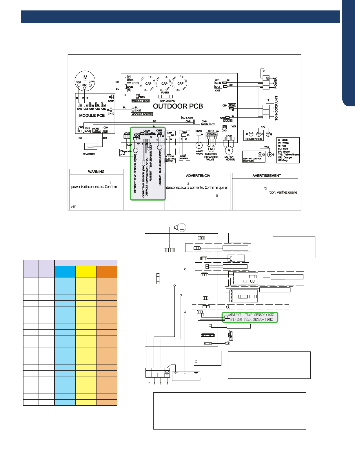
ERROR CODES AND TROUBLESHOOTING PAGE 43
ENGLISH
R:Red
●
W:White
Y:Yellow
Y/G:Yellow/Green
B:Black
BR:Brown
BL:Blue
PIPING TEMP.SENSOR(10K)
●
AMBIENT TEMP.SENSOR(10K)
POWER BUTTON
Notes:
1.The dotted parts are optiona
●
l.
2.The two pins of CN51 should be shorted,
when the J6 is cuted off.
M
FUSE1
CN7
T3.15A/250VAC
TO OUTDOOR UNIT
1(N) (C)
3
(L)
2
WB
Y/G
GND
CN6
R
(L)
CN21
N
COMM
CN51
CN9
CN17
CN23'
CN35
CN34
ROOM CARD
CN5
DC FAN MOTOR
CN11'
DISPLAY BOARD
Model selection:
●
24K model-23 code - BM1 - 1
●
off 2 off
24K model-26 code - BM1 - 1 off 2 on
WIRED CONTROLLER
UP-DOWN STEPMOTOR
LEFT & RIGHT STEPMOTOR
WIFI
CN14
Notes:Before replacing the board,it
is necessary to ensure that the
machine is matched with the board
code
CN56 HUMAN SENSOR
CN38
CN27'
Y/G
GND
WK-B
EVAPORATOR
ELECTRIC
CONTROL BOX
COVER
GND
Y/G
RJ45
Diagnostic
port
CN5
CN1
CN2
SW1
OFF OFF OFF OFF
CN3 CN4
CN2
CN6
CN4
CN3
CENTRALIZED CONTROLLER
SW2
OFF OFF OFF OFF OFF OFF OF F OFF
CN36
OUTDOOR UNIT WIRING DIAGRAM
COMPRESSOR
●
●
B
Y/G
123(C)
N
L
BL
BR
BR
BR
BL
Y/G
Y/G
0011520512
Electrical Shock Hazard
Capacitor retains charge a er
voltage at capacitor has dissipated
(<10V DC) with hand held voltmeter
before servicing. LED2 light
between CN24 and CN26 should be
Riesgo de Descarga Eléctrica
El capacitor re ene carga una vez
voltaje del capacitor se haya disipado (<10V
DC) apoyando la mano sobre el vol metro
antes de realizar el servicio técnico. La luz
LED2 que se encuentra entre CN24 y CN26
deberá estar apagada.
Risque de choc électrique
Le condensateur conserve sa charge après la
coupure de l’alimenta on électrique. Avant
de procéder à une répara
courant au condensateur s’est dissipé
(<10 VCC) à l’aide d’un voltmètre manuel. Le
voyant LED2 entre CN24 et CN26 doit être
éteint.
Error Codes and Troubleshooting
Error Code: F6/LED1: 12 Flash, F7/LED1: 11 Flash, F21/LED1: 10 Flash, F25/LED1: 13 Flash,
E1/LED1: No Flash, E2/LED1: No Flash
Wiring Diagram Reference
Sensor Resistance Table
°F °C
Normal (KΩ
10K
SENSORS
23K
SENSORS
50K
SENSORS
-0.4 -18 75.44 235.90 5494.21
5.0 -15 64.30 196.61 4558.19
10.4 -12 54.99 164.40 3795.39
14.0 -10 49.62 146.15 3365.73
21.2 -6 40.58 115.95 2658.81
24.8 -4 36.77 103.46 2368.32
32.0 0 30.30 82.69 1887.00
35.6 2 27.55 74.07 1687.81
41.0 5 23.95 62.94 1431.28
44.6 7 21.84 56.57 1284.36
50.0 10 19.06 48.31 1094.32
55.4 13 16.68 41.40 934.94
59.0 15 15.28 37.41 843.05
64.4 18 13.42 32.22 723.41
69.8 21 11.81 27.83 622.32
75.2 24 10.42 24.11 536.65
77.0 25 10.00 23.00 511.08
80.6 27 9.21 20.95 464.05
86.0 30 8.16 18.25 402.24
89.6 32 7.54 16.67 366.13
95.0 35 6.70 14.59 318.52
100.4 38 5.97 12.79 277.70

ERROR CODES AND TROUBLESHOOTING
PAGE 44
ENGLISH
R:Red
●
W:White
Y:Yellow
Y/G:Yellow/Green
B:Black
BR:Brown
BL:Blue
PIPING TEMP.SENSOR(10K)
●
AMBIENT TEMP.SENSOR(10K)
POWER BUTTON
Notes:
1.The dotted parts are optiona
●
l.
2.The two pins of CN51 should be shorted,
when the J6 is cuted off.
M
FUSE1
CN7
T3.15A/250VAC
TO OUTDOOR UNIT
1(N) (C)
3
(L)
2
WB
Y/G
GND
CN6
R
(L)
CN21
N
COMM
CN51
CN9
CN17
CN23'
CN35
CN34
ROOM CARD
CN5
DC FAN MOTOR
CN11'
DISPLAY BOARD
Model selection:
WIRED CONTROLLER
UP-DOWN STEPMOTOR
LEFT & RIGHT STEPMOTOR
WIFI
CN14
Notes:Before replacing the board,it
is necessary to ensure that the
machine is matched with the board
code
CN56 HUMAN SENSOR
CN38
CN27'
Y/G
GND
WK-B
EVAPORATOR
ELECTRIC
CONTROL BOX
COVER
GND
Y/G
RJ45
Diagnostic
port
CN5
CN1
CN2
SW1
OFF OFF OFF OFF
CN3 CN4
CN2
CN6
CN4
CN3
CENTRALIZED CONTROLLER
SW2
OFF OFF OFF OFF OFF OFF OF F OFF
CN36
model-23 code - BM1 - 1 off 2 off
model-26 code - BM1 - 1 off 2 on
2 off
30K
30K
36K
36K
model-33 code - BM1 - 1 on
model-35 code - BM1 - 1 on 2 on
OUTDOOR UNIT WIRING DIAGRAM
COMPRESSOR
●
●
B
Y/G
123(C)
N
L
BL
BR
BR
BR
BL
Y/G
Y/G
0011520512
Electrical Shock Hazard
Capacitor retains charge a er
voltage at capacitor has dissipated
(<10V DC) with hand held voltmeter
before servicing. LED2 light
between CN24 and CN26 should be
Riesgo de Descarga Eléctrica
El capacitor re ene carga una vez
voltaje del capacitor se haya disipado (<10V
DC) apoyando la mano sobre el vol metro
antes de realizar el servicio técnico. La luz
LED2 que se encuentra entre CN24 y CN26
deberá estar apagada.
Risque de choc électrique
Le condensateur conserve sa charge après la
coupure de l’alimenta on électrique. Avant
de procéder à une répara
courant au condensateur s’est dissipé
(<10 VCC) à l’aide d’un voltmètre manuel. Le
voyant LED2 entre CN24 et CN26 doit être
éteint.
Error Code: F6/LED1: 12 Flash, F7/LED1: 11 Flash, F21/LED1: 10 Flash, F25/LED1: 13 Flash,
E1/LED1: No Flash, E2/LED1: No Flash
Wiring Diagram Reference
Sensor Resistance Table
°F °C
Normal (KΩ
10K
SENSORS
23K
SENSORS
50K
SENSORS
-0.4 -18 75.44 235.90 5494.21
5.0 -15 64.30 196.61 4558.19
10.4 -12 54.99 164.40 3795.39
14.0 -10 49.62 146.15 3365.73
21.2 -6 40.58 115.95 2658.81
24.8 -4 36.77 103.46 2368.32
32.0 0 30.30 82.69 1887.00
35.6 2 27.55 74.07 1687.81
41.0 5 23.95 62.94 1431.28
44.6 7 21.84 56.57 1284.36
50.0 10 19.06 48.31 1094.32
55.4 13 16.68 41.40 934.94
59.0 15 15.28 37.41 843.05
64.4 18 13.42 32.22 723.41
69.8 21 11.81 27.83 622.32
75.2 24 10.42 24.11 536.65
77.0 25 10.00 23.00 511.08
80.6 27 9.21 20.95 464.05
86.0 30 8.16 18.25 402.24
89.6 32 7.54 16.67 366.13
95.0 35 6.70 14.59 318.52
100.4 38 5.97 12.79 277.70
Error Codes and Troubleshooting
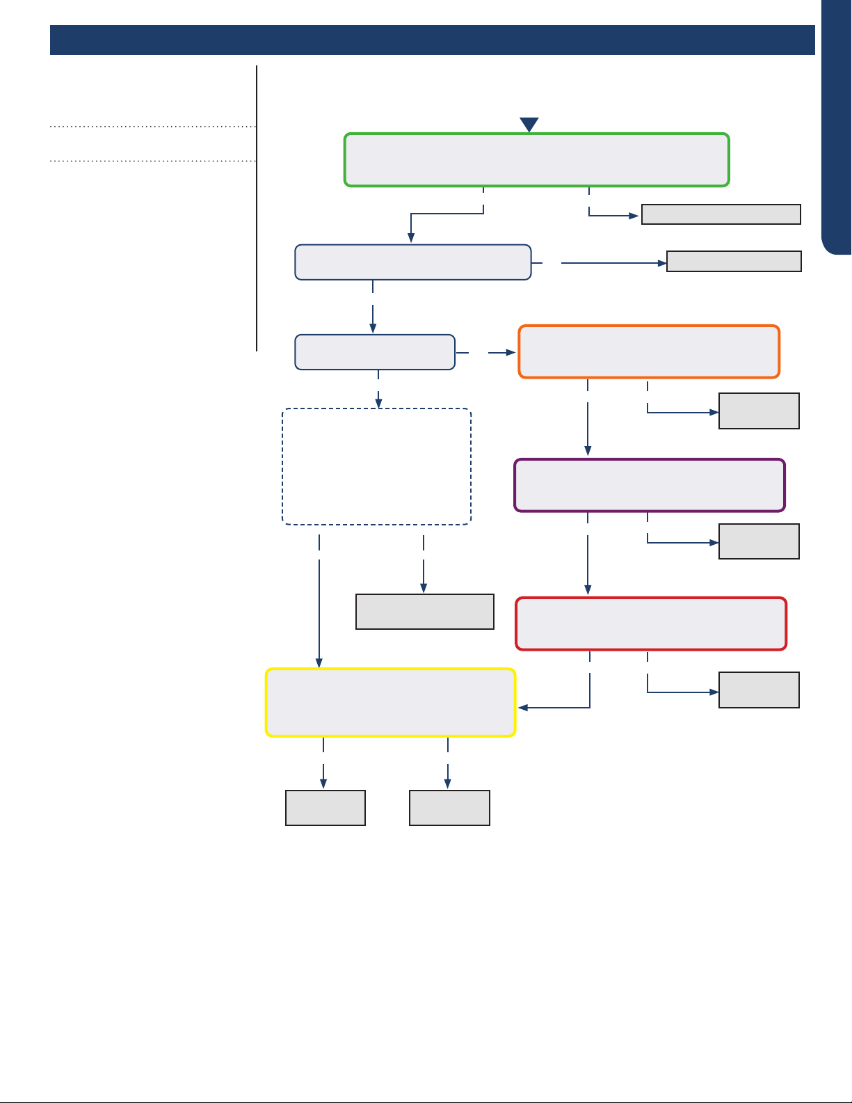
ERROR CODES AND TROUBLESHOOTING PAGE 45
ENGLISH
Error Codes and Troubleshooting
No
Error Code (Indoor/Outdoor)
F8/LED1: 9 Flash
Outdoor DC Fan Motor Fault
Completethe“CheckThisFirst”Flow
Chartbeforecontinuing.
Models:
AW24TL2HFA
AW30TL2HFA
AW36TL2HFA
ASYW24TRDFA
ASYW30TRDFA
ASYW36TRDFA
1U24TL2HFA
1U3036TL2HFA
ASH124TRDFA
ASH3036TRDFA
Yes
Yes
Yes
Yes
NoYes
No
Yes No
Add wind bae /
protection from wind.
Fix incoming power supply
Replace the fan motor
Replace the
fan motor.
Replace the
main board.
Start
Check the incoming voltage.
Is it 208/230VAC (+/- 10%) between L1/L2?
104/115VAC (+/- 10%) from L1 to GROUND and L2 to GROUND?
With the power o, turn the fan by hand.
Does it move / rotate smoothly?
Re-apply power. Does the
fan come on and spin?
Measure DC voltage at fan motor plug
CN21 between the Pin 6 (BLUE) and Pin 3
(BLACK) wire while spinning the fan motor.
Does it generate 2~9VDC?
No
No
No
Replace the
main board.
Replace the
main board.
Replace the
main board.
Measure DC voltage at fan motor plug CN21
between Pin 1 (RED) and Pin 3 (BLACK).
Does it measure 300~380VDC (+/-10%)?
Measure DC voltage at fan motor plug CN21
between Pin 4 (WHITE) and Pin 3 (BLACK).
Does it measure between 13.5-16.5VDC?
Measure DC voltage at fan motor plug CN21
between Pin 5 (YELLOW) and Pin 3 (BLACK).
Does it measure between 2-6VDC?
Before going to the next step, is
the unit in an area susceptible to
high winds? High winds blowing into
the fan may cause added resistance
and subsequently lower fan speeds
enough to cause the unit to fault. If
this is the case the unit only faults
during windy situations a wind bae
may need to be added.
Not Windy Windy
Yes
See following page
for wiring diagram and
relevant color-coded
test positions.
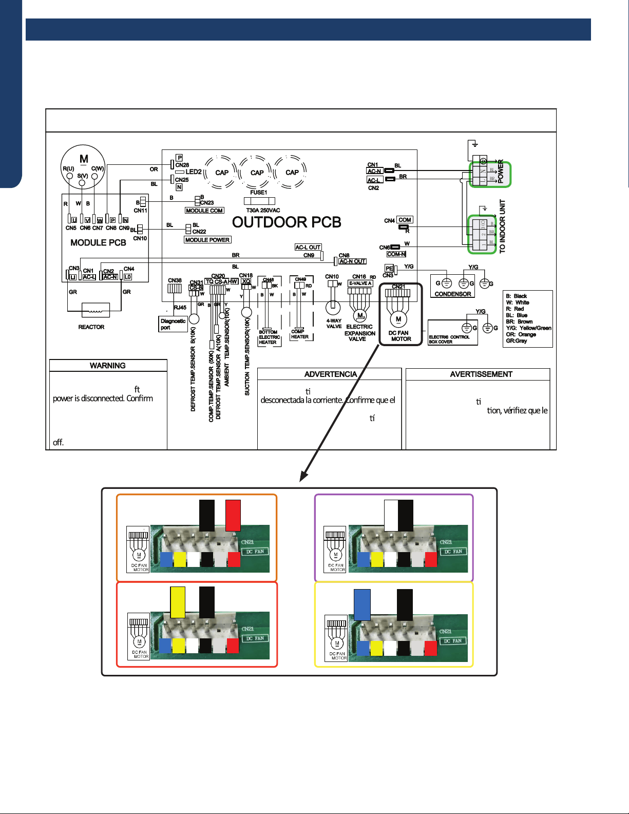
ERROR CODES AND TROUBLESHOOTING
PAGE 46
ENGLISH
OUTDOOR UNIT WIRING DIAGRAM
COMPRESSOR
●
●
B
Y/G
123(C)
N
L
BL
BR
BR
BR
BL
Y/G
Y/G
0011520512
Electrical Shock Hazard
Capacitor retains charge a er
voltage at capacitor has dissipated
(<10V DC) with hand held voltmeter
before servicing. LED2 light
between CN24 and CN26 should be
Riesgo de Descarga Eléctrica
El capacitor re ene carga una vez
voltaje del capacitor se haya disipado (<10V
DC) apoyando la mano sobre el vol metro
antes de realizar el servicio técnico. La luz
LED2 que se encuentra entre CN24 y CN26
deberá estar apagada.
Risque de choc électrique
Le condensateur conserve sa charge après la
coupure de l’alimenta on électrique. Avant
de procéder à une répara
courant au condensateur s’est dissipé
(<10 VCC) à l’aide d’un voltmètre manuel. Le
voyant LED2 entre CN24 et CN26 doit être
éteint.
Error Codes and Troubleshooting
Error Code: F8/LED1: 9 Flash
Wiring Diagram Reference
RED
WHITE
BLACK
1/3456 1/3456
1/3456
BLUE
1/3456
BLACK
YELLOW
BLACK
BLACK
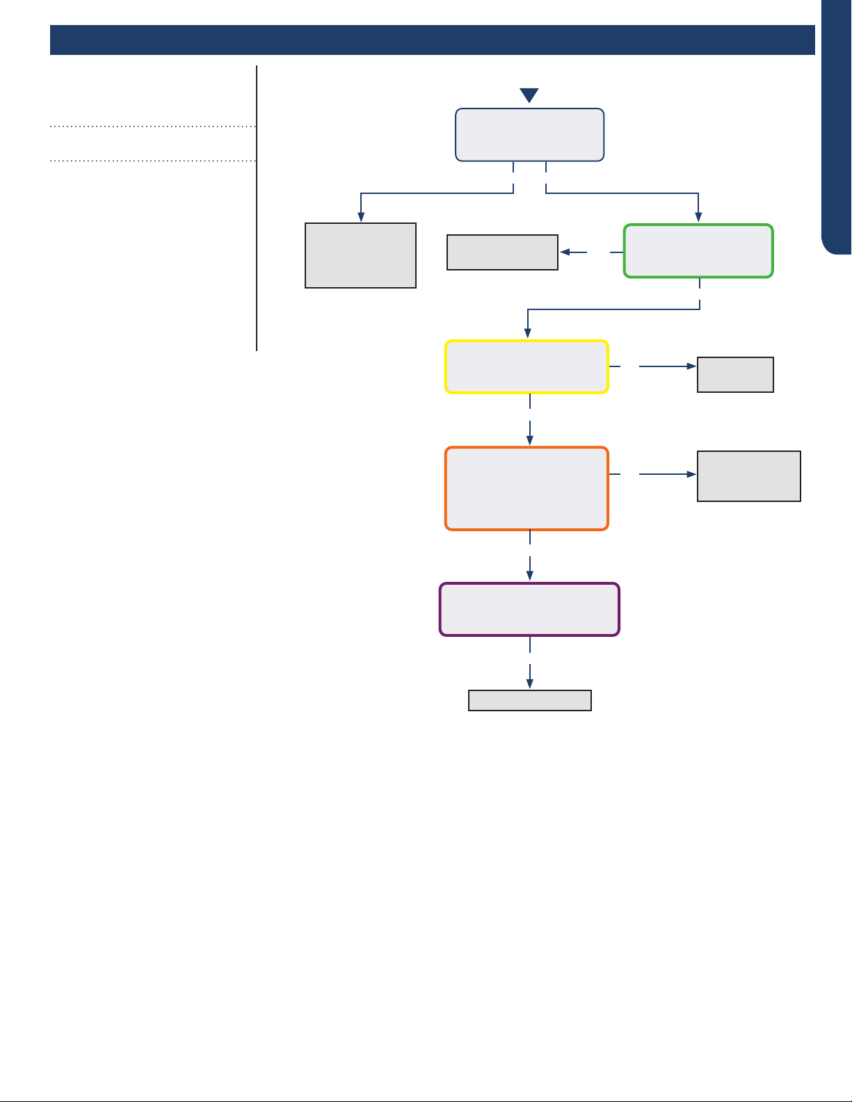
ERROR CODES AND TROUBLESHOOTING PAGE 47
ENGLISH
Error Codes and Troubleshooting
No
No
Yes
Momentary loss
of building power
or acceptable
power quality
Replace
compressor
Replace compressor
Replace
IPM
Repair or
replace wiring or
connections
When power is o for 5
min. and turned back on,
the compressor runs?
A windings or grounding
check shows issues with
compressor?
There is 50-200 VAC
across the U, V, and W
solder points on the IPM?
The compressor wires are
on the correct terminals,
free of breaks and the
connections at both end
are secure?
There is substantially more
than 5 VDC or 15 VDC pulsing
at CN23 on the PCB?
Yes
Yes
Yes
Yes
No
No
Error Code (Indoor/Outdoor)
F11/LED1: 18 Flash
Loss of Compressor Synchronization
Completethe“CheckThisFirst”Flow
Chartbeforecontinuing.
Models:
AW24TL2HFA
AW30TL2HFA
AW36TL2HFA
ASYW24TRDFA
ASYW30TRDFA
ASYW36TRDFA
1U24TL2HFA
1U3036TL2HFA
ASH124TRDFA
ASH3036TRDFA
Start
See following page
for wiring diagram and
relevant color-coded
test positions.
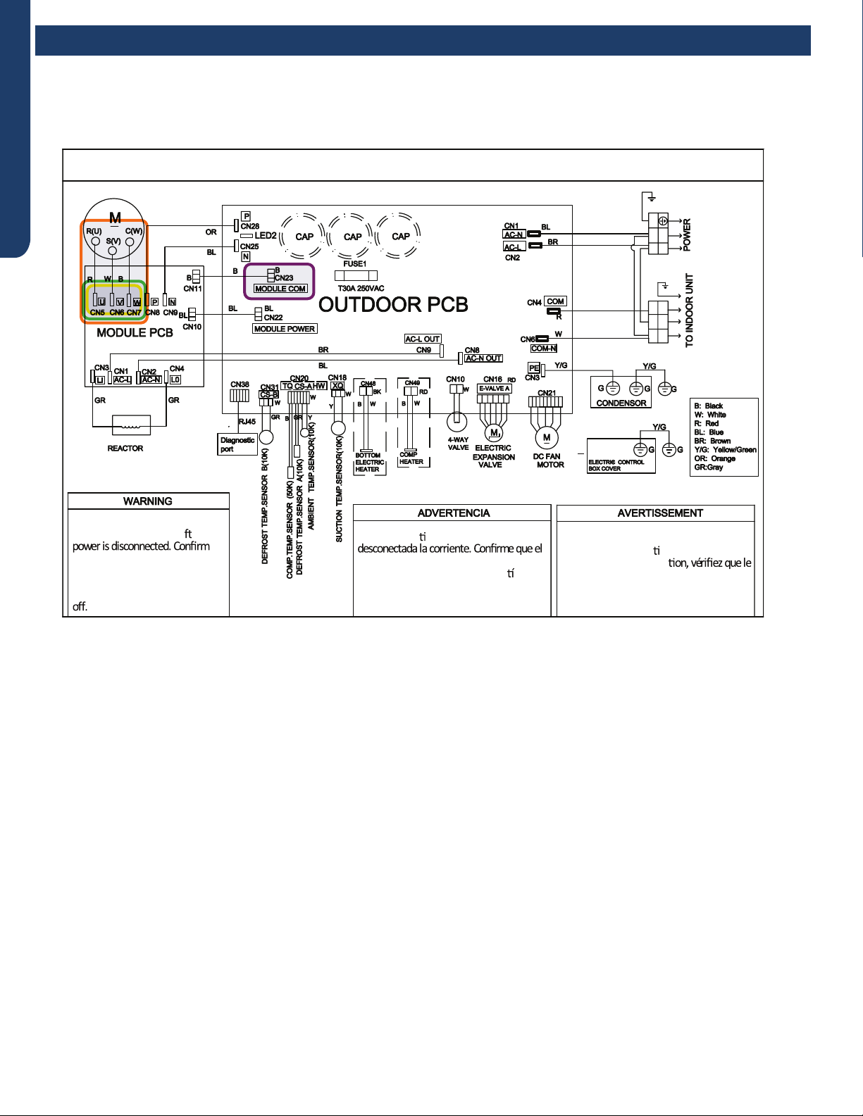
ERROR CODES AND TROUBLESHOOTING
PAGE 48
ENGLISH
OUTDOOR UNIT WIRING DIAGRAM
COMPRESSOR
●
●
B
Y/G
123(C)
N
L
BL
BR
BR
BR
BL
Y/G
Y/G
0011520512
Electrical Shock Hazard
Capacitor retains charge a er
voltage at capacitor has dissipated
(<10V DC) with hand held voltmeter
before servicing. LED2 light
between CN24 and CN26 should be
Riesgo de Descarga Eléctrica
El capacitor re ene carga una vez
voltaje del capacitor se haya disipado (<10V
DC) apoyando la mano sobre el vol metro
antes de realizar el servicio técnico. La luz
LED2 que se encuentra entre CN24 y CN26
deberá estar apagada.
Risque de choc électrique
Le condensateur conserve sa charge après la
coupure de l’alimenta on électrique. Avant
de procéder à une répara
courant au condensateur s’est dissipé
(<10 VCC) à l’aide d’un voltmètre manuel. Le
voyant LED2 entre CN24 et CN26 doit être
éteint.
Error Codes and Troubleshooting
Error Code: F11/LED1: 18 Flash
Wiring Diagram Reference
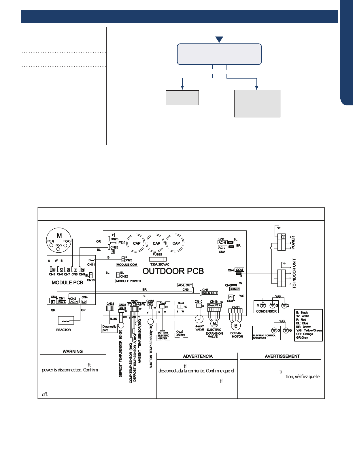
ERROR CODES AND TROUBLESHOOTING PAGE 49
ENGLISH
Error Codes and Troubleshooting
Yes No
The 10-minute
reboot has
corrected the
issue
Replace
PCB
After 10 minutes with the power
o, the 1-ash reappears with
power turned back on?
Error Code (Indoor/Outdoor)
F12/LED1: 1 Flash
EEPROM Error
Completethe“CheckThisFirst”Flow
Chartbeforecontinuing.
Models:
AW24TL2HFA
AW30TL2HFA
AW36TL2HFA
ASYW24TRDFA
ASYW30TRDFA
ASYW36TRDFA
1U24TL2HFA
1U3036TL2HFA
ASH124TRDFA
ASH3036TRDFA
Wiring Diagram Reference
OUTDOOR UNIT WIRING DIAGRAM
COMPRESSOR
●
●
B
Y/G
123(C)
N
L
BL
BR
BR
BR
BL
Y/G
Y/G
0011520512
Electrical Shock Hazard
Capacitor retains charge a er
voltage at capacitor has dissipated
(<10V DC) with hand held voltmeter
before servicing. LED2 light
between CN24 and CN26 should be
Riesgo de Descarga Eléctrica
El capacitor re ene carga una vez
voltaje del capacitor se haya disipado (<10V
DC) apoyando la mano sobre el vol metro
antes de realizar el servicio técnico. La luz
LED2 que se encuentra entre CN24 y CN26
deberá estar apagada.
Risque de choc électrique
Le condensateur conserve sa charge après la
coupure de l’alimenta on électrique. Avant
de procéder à une répara
courant au condensateur s’est dissipé
(<10 VCC) à l’aide d’un voltmètre manuel. Le
voyant LED2 entre CN24 et CN26 doit être
éteint.
Start
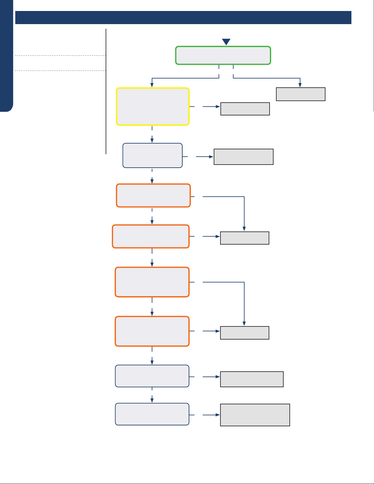
ERROR CODES AND TROUBLESHOOTING
PAGE 50
ENGLISH
Error Codes and Troubleshooting
Yes
Yes
Yes
Yes
Yes
Yes
Yes
No
No
No
No
No
No
No
No
Yes No
Replace PCB
Replace PCB
Replace Motor
Replace/Repair EEV
Coil
Recover refrigerant, check
for leaks, evacuate, and
re-charge per nameplate
Replace sensor
Wash coil, blower
wheel and/or lter
There is 5 VDC at CN6 on the Indoor
PCB across the black senor wires?
The Coil and Ambient
Sensors’ resistances are
within 3% of the value
listed in the Service Manual
sensor resistance table?
The coil, blower
wheel, and lter are
free of dirt or debris?
There is DCV at the motor
PCB connections:
RD to BK: 310-334VDC?
There is DCV at the motor
PCB connections:
WH to BK: 15VDC
There is DCV at the motor
PCB connections:
YL to BK: 1-4VDC running,
0 when o?
There is DCV at the motor
PCB connections:
BL to BK: 4-8VDC running,
14VDC when o?
Is the EEV coil properly
seated and the coil
resistance correct?
The refrigerant charge has
been veried against the
nameplate value?
Error Code (Indoor/Outdoor)
E5/LED1: 22 Flash
Coil Frost Protection
Completethe“CheckThisFirst”Flow
Chartbeforecontinuing.
Models:
AW24TL2HFA
AW30TL2HFA
AW36TL2HFA
ASYW24TRDFA
ASYW30TRDFA
ASYW36TRDFA
1U24TL2HFA
1U3036TL2HFA
ASH124TRDFA
ASH3036TRDFA
See following page for
wiring diagram, relevant
color-coded test
positions, sensor and
EEV resistance values.
Start
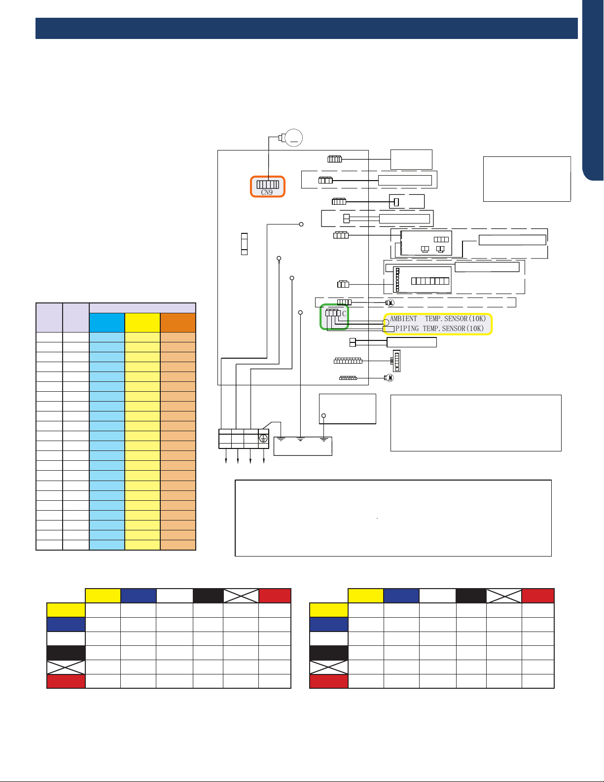
ERROR CODES AND TROUBLESHOOTING PAGE 51
ENGLISH
R:Red
●
W:White
Y:Yellow
Y/G:Yellow/Green
B:Black
BR:Brown
BL:Blue
PIPING TEMP.SENSOR(10K)
●
AMBIENT TEMP.SENSOR(10K)
POWER BUTTON
Notes:
1.The dotted parts are optiona
●
l.
2.The two pins of CN51 should be shorted,
when the J6 is cuted off.
M
FUSE1
CN7
T3.15A/250VAC
TO OUTDOOR UNIT
1(N) (C)
3
(L)
2
WB
Y/G
GND
CN6
R
(L)
CN21
N
COMM
CN51
CN9
CN17
CN23'
CN35
CN34
ROOM CARD
CN5
DC FAN MOTOR
CN11'
DISPLAY BOARD
Model selection:
●
24K model-23 code - BM1 - 1
●
off 2 off
24K model-26 code - BM1 - 1 off 2 on
WIRED CONTROLLER
UP-DOWN STEPMOTOR
LEFT & RIGHT STEPMOTOR
WIFI
CN14
Notes:Before replacing the board,it
is necessary to ensure that the
machine is matched with the board
code
CN56 HUMAN SENSOR
CN38
CN27'
Y/G
GND
WK-B
EVAPORATOR
ELECTRIC
CONTROL BOX
COVER
GND
Y/G
RJ45
Diagnostic
port
CN5
CN1
CN2
SW1
OFF OFF OFF OFF
CN3 CN4
CN2
CN6
CN4
CN3
CENTRALIZED CONTROLLER
SW2
OFF OFF OFF OF F OFF OFF OFF OFF
CN36
Error Codes and Troubleshooting
Error Code: E5/LED1: 22 Flash
Wiring Diagram Reference
Sensor Resistance Table
°F °C
Normal (KΩ
10K
SENSORS
23K
SENSORS
50K
SENSORS
-0.4 -18 75.44 235.90 5494.21
5.0 -15 64.30 196.61 4558.19
10.4 -12 54.99 164.40 3795.39
14.0 -10 49.62 146.15 3365.73
21.2 -6 40.58 115.95 2658.81
24.8 -4 36.77 103.46 2368.32
32.0 0 30.30 82.69 1887.00
35.6 2 27.55 74.07 1687.81
41.0 5 23.95 62.94 1431.28
44.6 7 21.84 56.57 1284.36
50.0 10 19.06 48.31 1094.32
55.4 13 16.68 41.40 934.94
59.0 15 15.28 37.41 843.05
64.4 18 13.42 32.22 723.41
69.8 21 11.81 27.83 622.32
75.2 24 10.42 24.11 536.65
77.0 25 10.00 23.00 511.08
80.6 27 9.21 20.95 464.05
86.0 30 8.16 18.25 402.24
89.6 32 7.54 16.67 366.13
95.0 35 6.70 14.59 318.52
100.4 38 5.97 12.79 277.70
EEV Resistance Values
EEV (6-pin, 6 wire)
Yellow Blue White Black Red
Yellow - OL 92 Ω OL 46 Ω OL
Blue - - OL 92 Ω OL 46 Ω
White - - - OL 46 Ω OL
Black - - - - OL 46 Ω
- - - - - OL
Red - - - - - -
EEV (6-pin, 5 wire)
Yellow Blue White Black Red
Yellow - 92 Ω 92 Ω 92 Ω - 46 Ω
Blue - - 92 Ω 92 Ω - 46 Ω
White - - - 92 Ω - 46 Ω
Black - - - - - 46 Ω
- - - - - -
Red - - - - - -
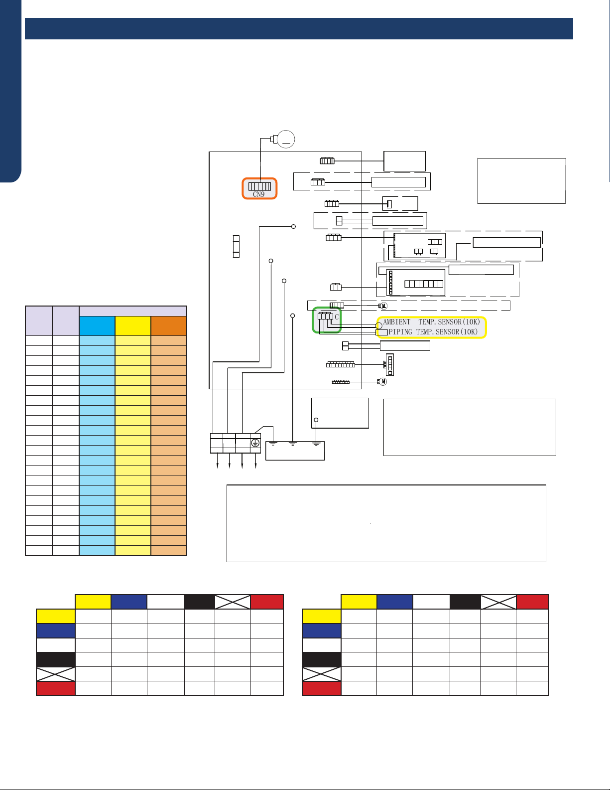
ERROR CODES AND TROUBLESHOOTING
PAGE 52
ENGLISH
Error Codes and Troubleshooting
R:Red
●
W:White
Y:Yellow
Y/G:Yellow/Green
B:Black
BR:Brown
BL:Blue
PIPING TEMP.SENSOR(10K)
●
AMBIENT TEMP.SENSOR(10K)
POWER BUTTON
Notes:
1.The dotted parts are optiona
●
l.
2.The two pins of CN51 should be shorted,
when the J6 is cuted off.
M
FUSE1
CN7
T3.15A/250VAC
TO OUTDOOR UNIT
1(N) (C)
3
(L)
2
WB
Y/G
GND
CN6
R
(L)
CN21
N
COMM
CN51
CN9
CN17
CN23'
CN35
CN34
ROOM CARD
CN5
DC FAN MOTOR
CN11'
DISPLAY BOARD
Model selection:
WIRED CONTROLLER
UP-DOWN STEPMOTOR
LEFT & RIGHT STEPMOTOR
WIFI
CN14
Notes:Before replacing the board,it
is necessary to ensure that the
machine is matched with the board
code
CN56 HUMAN SENSOR
CN38
CN27'
Y/G
GND
WK-B
EVAPORATOR
ELECTRIC
CONTROL BOX
COVER
GND
Y/G
RJ45
Diagnostic
port
CN5
CN1
CN2
SW1
OFF OFF OFF OFF
CN3 CN4
CN2
CN6
CN4
CN3
CENTRALIZED CONTROLLER
SW2
OFF OFF OFF OF F OFF OFF OFF OFF
CN36
model-23 code - BM1 - 1 off 2 off
model-26 code - BM1 - 1 off 2 on
2 off
30K
30K
36K
36K
model-33 code - BM1 - 1 on
model-35 code - BM1 - 1 on 2 on
Error Code: E5/LED1: 22 Flash
Wiring Diagram Reference
Sensor Resistance Table
°F °C
Normal (KΩ
10K
SENSORS
23K
SENSORS
50K
SENSORS
-0.4 -18 75.44 235.90 5494.21
5.0 -15 64.30 196.61 4558.19
10.4 -12 54.99 164.40 3795.39
14.0 -10 49.62 146.15 3365.73
21.2 -6 40.58 115.95 2658.81
24.8 -4 36.77 103.46 2368.32
32.0 0 30.30 82.69 1887.00
35.6 2 27.55 74.07 1687.81
41.0 5 23.95 62.94 1431.28
44.6 7 21.84 56.57 1284.36
50.0 10 19.06 48.31 1094.32
55.4 13 16.68 41.40 934.94
59.0 15 15.28 37.41 843.05
64.4 18 13.42 32.22 723.41
69.8 21 11.81 27.83 622.32
75.2 24 10.42 24.11 536.65
77.0 25 10.00 23.00 511.08
80.6 27 9.21 20.95 464.05
86.0 30 8.16 18.25 402.24
89.6 32 7.54 16.67 366.13
95.0 35 6.70 14.59 318.52
100.4 38 5.97 12.79 277.70
EEV Resistance Values
EEV (6-pin, 6 wire)
Yellow Blue White Black Red
Yellow - OL 92 Ω OL 46 Ω OL
Blue - - OL 92 Ω OL 46 Ω
White - - - OL 46 Ω OL
Black - - - - OL 46 Ω
- - - - - OL
Red - - - - - -
EEV (6-pin, 5 wire)
Yellow Blue White Black Red
Yellow - 92 Ω 92 Ω 92 Ω - 46 Ω
Blue - - 92 Ω 92 Ω - 46 Ω
White - - - 92 Ω - 46 Ω
Black - - - - - 46 Ω
- - - - - -
Red - - - - - -
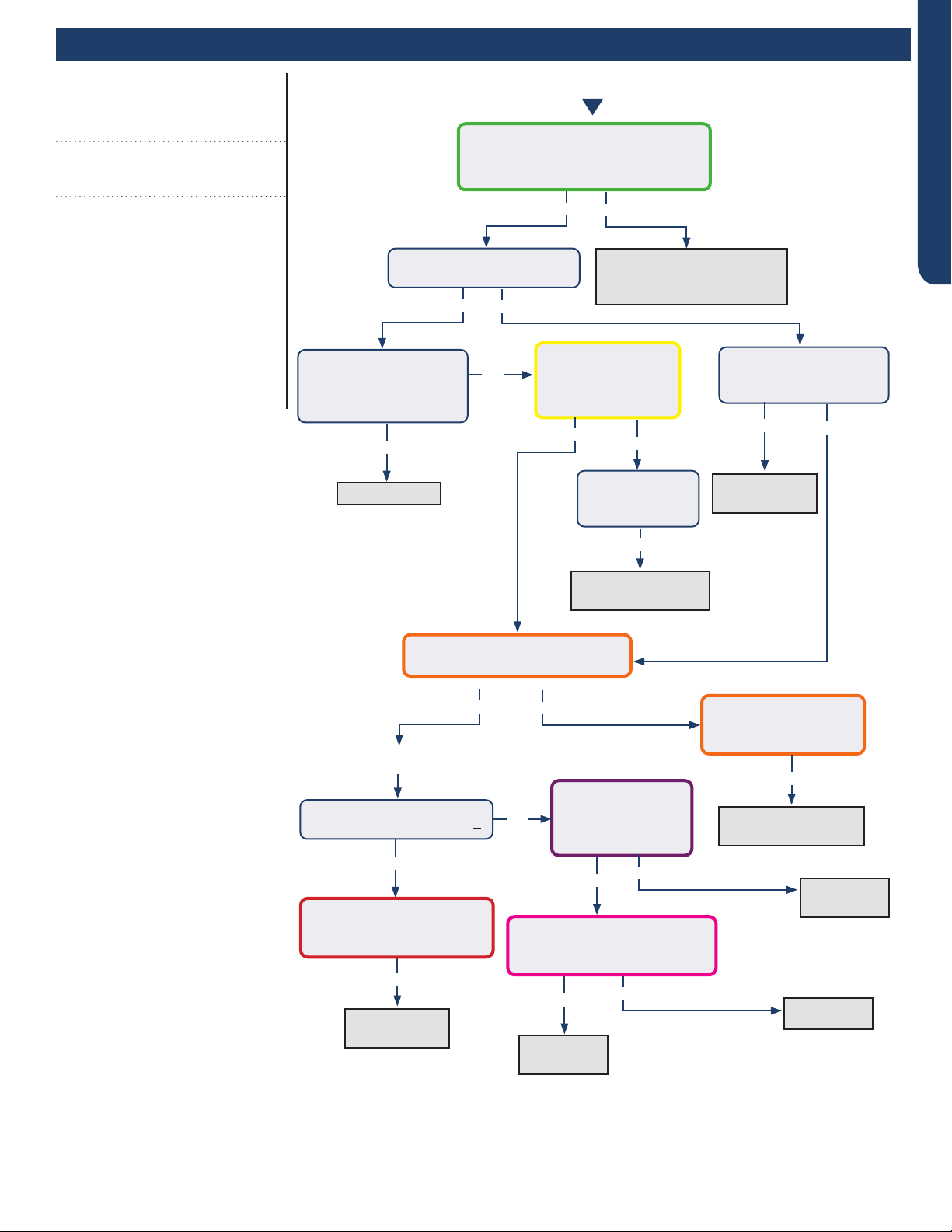
ERROR CODES AND TROUBLESHOOTING PAGE 53
ENGLISH
Error Codes and Troubleshooting
Reposition on correct
terminals, replace wire if
spliced or the incorrect type
Indoor PCB OK
The control wire is 14/4 stranded
copper on the correct terminals, with
no splices or loose connections?
Yes
No
Yes
Yes
No
No
Is the Indoor PCB LED
ashing 3 times per second?
Does the voltage
between L and C at
indoor unit uctuate
0~140VAC?
Is the voltage from
L to C at indoor unit
between 0~80VAC
(approx..)?
Is the Indoor PCB LED
pattern repeatedly
Flash…Flash…On?
Fault is with
outdoor PCB
Replace fan
motor
Replace INDOOR
PCB
Replace
PCB
Replace
PCB
Replace IPM
The communication
wire is broken
There is 0-80 VAC uctuating
between 1(N) and 3(C) at ID UNIT?
There is 230 VAC
at the PCB? Across
AC-L OUT & AC-N
OUT (CN9 & CN10)
There is less than 5 VDC at
CN22 (module power) and GND
(pins 1 and 2)?
The voltage between
1(N) and 3(C) is a xed
value at ID UNIT?
Go to outdoor PCB
No
Yes
Yes
Yes
Yes
Yes
Yes
Yes
No
No
Yes
Yes No
No
No
LED1 (center) is o
LED2 (upper left) is lighted?
With power o, disconnect
fan motor at CN21. LED1
lights with power back on?
The display is
lighted, yet the
LED is o?
Error Code (Indoor/Outdoor)
E7/LED1: 15 Flash
ID and OD Loss of Communication
Completethe“CheckThisFirst”Flow
ChartforbothIDandODunitsbefore
continuing.
Models:
AW24TL2HFA
AW30TL2HFA
AW36TL2HFA
ASYW24TRDFA
ASYW30TRDFA
ASYW36TRDFA
1U24TL2HFA
1U3036TL2HFA
ASH124TRDFA
ASH3036TRDFA
Start
See following page
for wiring diagram and
relevant color-coded
test positions.
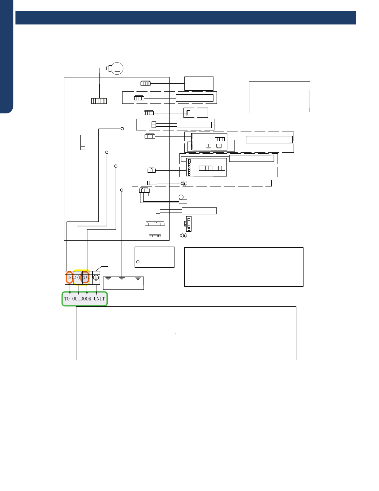
ERROR CODES AND TROUBLESHOOTING
PAGE 54
ENGLISH
R:Red
●
W:White
Y:Yellow
Y/G:Yellow/Green
B:Black
BR:Brown
BL:Blue
PIPING TEMP.SENSOR(10K)
●
AMBIENT TEMP.SENSOR(10K)
POWER BUTTON
Notes:
1.The dotted parts are optiona
●
l.
2.The two pins of CN51 should be shorted,
when the J6 is cuted off.
M
FUSE1
CN7
T3.15A/250VAC
TO OUTDOOR UNIT
1(N) (C)
3
(L)
2
WB
Y/G
GND
CN6
R
(L)
CN21
N
COMM
CN51
CN9
CN17
CN23'
CN35
CN34
ROOM CARD
CN5
DC FAN MOTOR
CN11'
DISPLAY BOARD
Model selection:
●
24K model-23 code - BM1 - 1
●
off 2 off
24K model-26 code - BM1 - 1 off 2 on
WIRED CONTROLLER
UP-DOWN STEPMOTOR
LEFT & RIGHT STEPMOTOR
WIFI
CN14
Notes:Before replacing the board,it
is necessary to ensure that the
machine is matched with the board
code
CN56 HUMAN SENSOR
CN38
CN27'
Y/G
GND
WK-B
EVAPORATOR
ELECTRIC
CONTROL BOX
COVER
GND
Y/G
RJ45
Diagnostic
port
CN5
CN1
CN2
SW1
OFF OFF OFF OFF
CN3 CN4
CN2
CN6
CN4
CN3
CENTRALIZED CONTROLLER
SW2
OFF OFF OFF OFF OF F OFF OFF OFF
CN36
Error Codes and Troubleshooting
Error Code: E7/LED1: 15 Flash
Wiring Diagram Reference
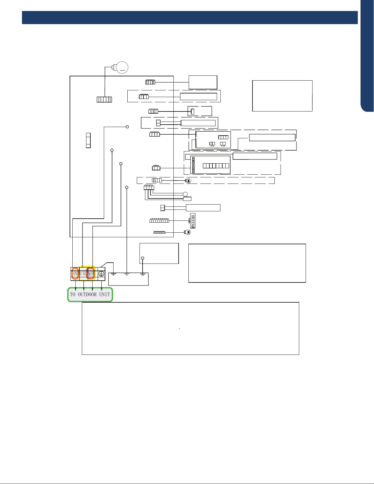
ERROR CODES AND TROUBLESHOOTING PAGE 55
ENGLISH
R:Red
●
W:White
Y:Yellow
Y/G:Yellow/Green
B:Black
BR:Brown
BL:Blue
PIPING TEMP.SENSOR(10K)
●
AMBIENT TEMP.SENSOR(10K)
POWER BUTTON
Notes:
1.The dotted parts are optiona
●
l.
2.The two pins of CN51 should be shorted,
when the J6 is cuted off.
M
FUSE1
CN7
T3.15A/250VAC
TO OUTDOOR UNIT
1(N) (C)
3
(L)
2
WB
Y/G
GND
CN6
R
(L)
CN21
N
COMM
CN51
CN9
CN17
CN23'
CN35
CN34
ROOM CARD
CN5
DC FAN MOTOR
CN11'
DISPLAY BOARD
Model selection:
WIRED CONTROLLER
UP-DOWN STEPMOTOR
LEFT & RIGHT STEPMOTOR
WIFI
CN14
Notes:Before replacing the board,it
is necessary to ensure that the
machine is matched with the board
code
CN56 HUMAN SENSOR
CN38
CN27'
Y/G
GND
WK-B
EVAPORATOR
ELECTRIC
CONTROL BOX
COVER
GND
Y/G
RJ45
Diagnostic
port
CN5
CN1
CN2
SW1
OFF OFF OFF OFF
CN3 CN4
CN2
CN6
CN4
CN3
CENTRALIZED CONTROLLER
SW2
OFF OFF OFF OFF OF F OFF OFF OFF
CN36
model-23 code - BM1 - 1 off 2 off
model-26 code - BM1 - 1 off 2 on
2 off
30K
30K
36K
36K
model-33 code - BM1 - 1 on
model-35 code - BM1 - 1 on 2 on
Error Codes and Troubleshooting
Error Code: E7/LED1: 15 Flash
Wiring Diagram Reference
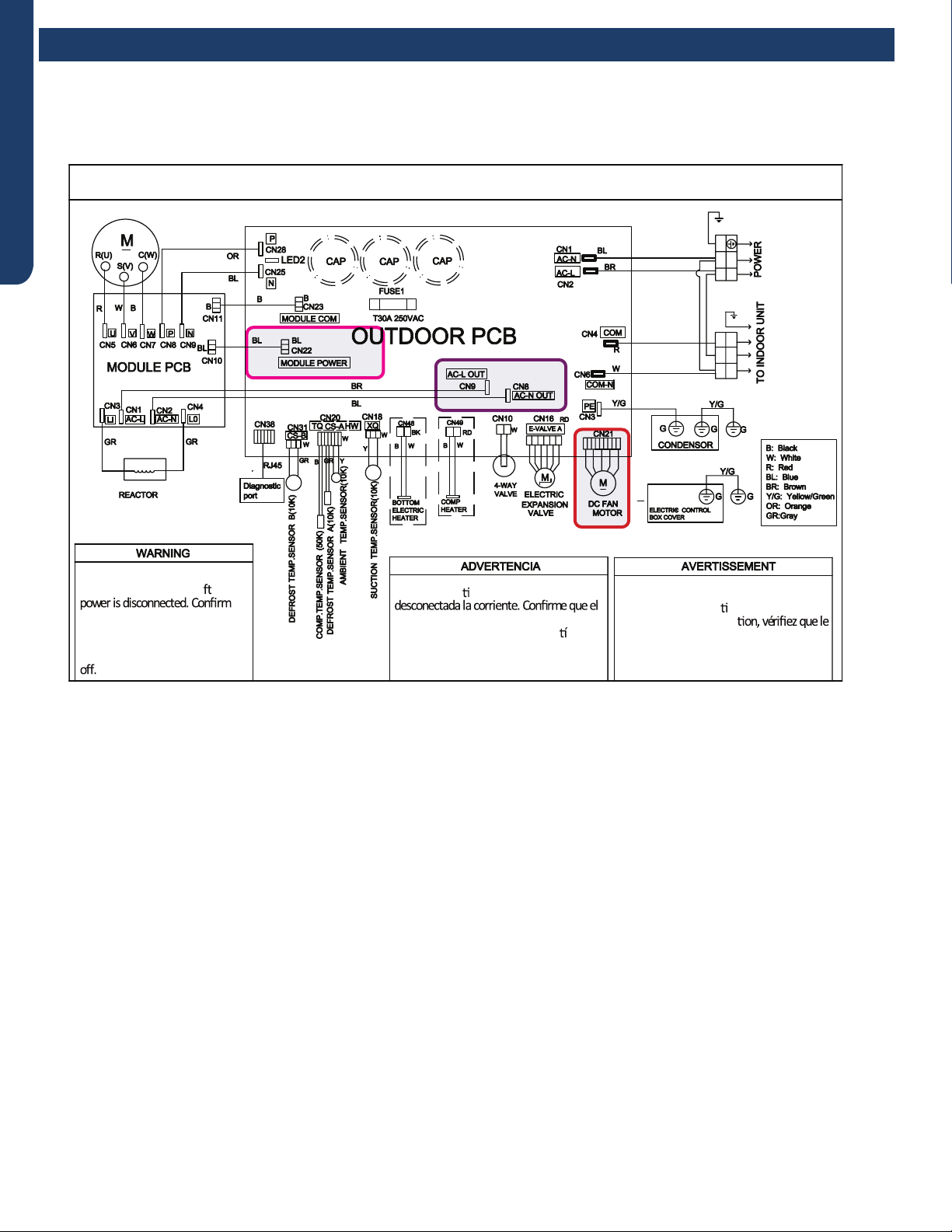
ERROR CODES AND TROUBLESHOOTING
PAGE 56
ENGLISH
Error Codes and Troubleshooting
Error Code: E7/LED1: 15 Flash
Wiring Diagram Reference
OUTDOOR UNIT WIRING DIAGRAM
COMPRESSOR
●
●
B
Y/G
123(C)
N
L
BL
BR
BR
BR
BL
Y/G
Y/G
0011520512
Electrical Shock Hazard
Capacitor retains charge a er
voltage at capacitor has dissipated
(<10V DC) with hand held voltmeter
before servicing. LED2 light
between CN24 and CN26 should be
Riesgo de Descarga Eléctrica
El capacitor re ene carga una vez
voltaje del capacitor se haya disipado (<10V
DC) apoyando la mano sobre el vol metro
antes de realizar el servicio técnico. La luz
LED2 que se encuentra entre CN24 y CN26
deberá estar apagada.
Risque de choc électrique
Le condensateur conserve sa charge après la
coupure de l’alimenta on électrique. Avant
de procéder à une répara
courant au condensateur s’est dissipé
(<10 VCC) à l’aide d’un voltmètre manuel. Le
voyant LED2 entre CN24 et CN26 doit être
éteint.
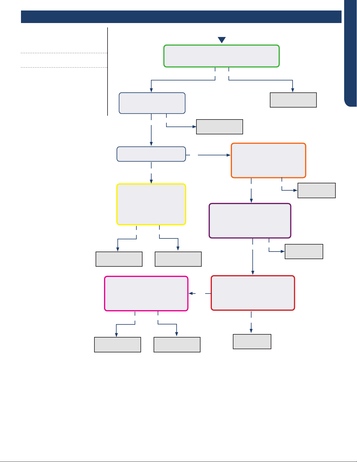
ERROR CODES AND TROUBLESHOOTING PAGE 57
ENGLISH
Error Codes and Troubleshooting
Error Code (Indoor)
E14
Indoor Fan Motor Failure
Completethe“CheckThisFirst”Flow
Chartbeforecontinuing.
Models:
AW24TL2HFA
AW30TL2HFA
AW36TL2HFA
ASYW24TRDFA
ASYW30TRDFA
ASYW36TRDFA
Yes
Yes
Yes
Yes
No
Yes No
No
Fix incoming
power supply
Replace the fan
motor
Replace the main
board.
Replace the fan
motor
Replace the
main board.
Replace the
main board.
Replace the
main board.
Start
With the power o, turn
the fan by hand. Does it
move / rotate smoothly?
Check the incoming voltage. Is it 208/230VAC
(+/- 10%) between L1/L2? 104/115VAC (+/-
10%) from L1 to GROUND and L2 to GROUND?
Re-apply power. Does the
fan come on and spin?
Measure DC voltage at fan
motor plug CN9 between
the Pin 7 (BLUE) and Pin
4 (BLACK) wire while
spinning the fan motor.
Does it generate 2~9VDC?
Measure DC voltage at fan
motor plug CN9 between Pin
1 (RED) and Pin 4 (BLACK).
Does it measure 300~380VDC
(+/-10%)?
Measure DC voltage at fan motor
plug CN9 between Pin 5 (WHITE)
and Pin 4 (BLACK).
Does it measure between
13.5-16.5VDC?
No
No
No
Yes
Replace the main
board.
Replace the fan
motor
Measure DC voltage at fan
motor plug CN9 between Pin 6
(YELLOW) and Pin 4 (BLACK).
Does it measure between
2-6VDC?
Measure DC voltage at fan motor
plug CN9 between the Pin 7
(BLUE) and Pin 4 (BLACK) wire
while spinning the fan motor.
Does it generate 2~9VDC?
No
Yes No
Yes
See following page
for wiring diagram and
relevant color-coded
test positions.
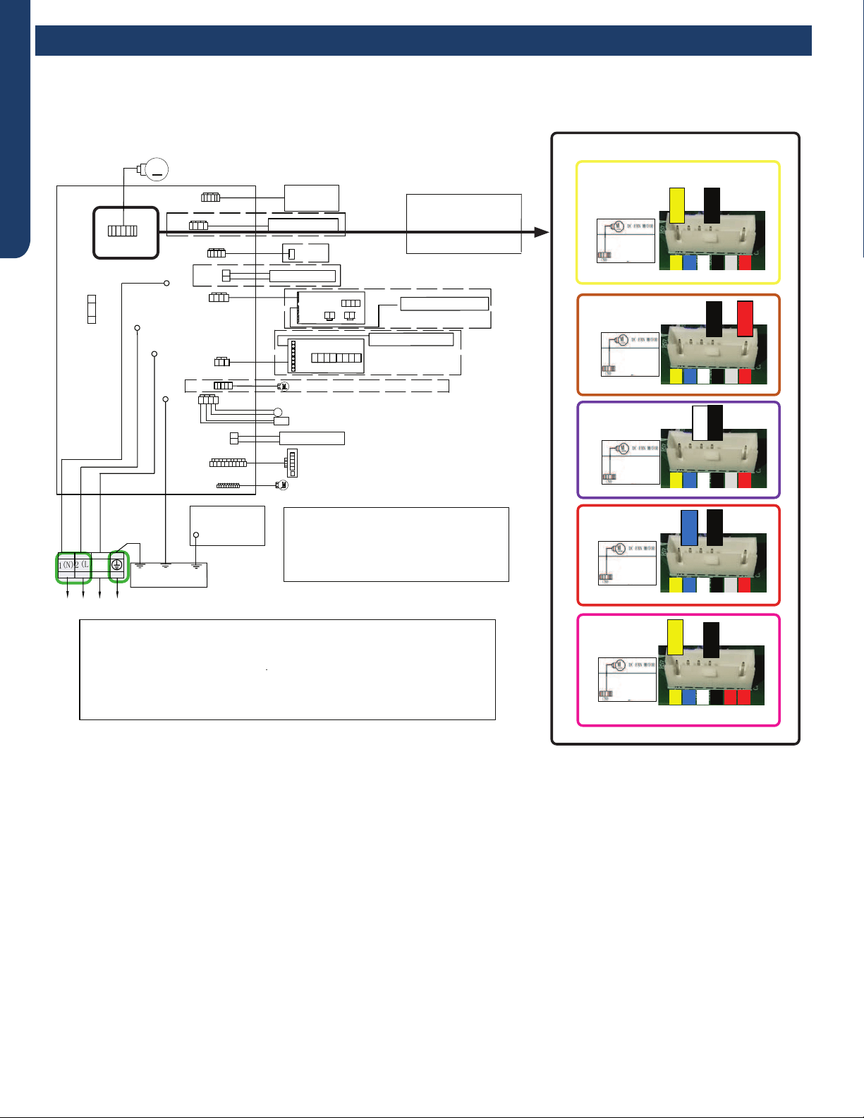
ERROR CODES AND TROUBLESHOOTING
PAGE 58
ENGLISH
R:Red
●
W:White
Y:Yellow
Y/G:Yellow/Green
B:Black
BR:Brown
BL:Blue
PIPING TEMP.SENSOR(10K)
●
AMBIENT TEMP.SENSOR(10K)
POWER BUTTON
Notes:
1.The dotted parts are optiona
●
l.
2.The two pins of CN51 should be shorted,
when the J6 is cuted off.
M
FUSE1
CN7
T3.15A/250VAC
TO OUTDOOR UNIT
1(N) (C)
3
(L)
2
WB
Y/G
GND
CN6
R
(L)
CN21
N
COMM
CN51
CN9
CN17
CN23'
CN35
CN34
ROOM CARD
CN5
DC FAN MOTOR
CN11'
DISPLAY BOARD
Model selection:
●
24K model-23 code - BM1 - 1
●
off 2 off
24K model-26 code - BM1 - 1 off 2 on
WIRED CONTROLLER
UP-DOWN STEPMOTOR
LEFT & RIGHT STEPMOTOR
WIFI
CN14
Notes:Before replacing the board,it
is necessary to ensure that the
machine is matched with the board
code
CN56 HUMAN SENSOR
CN38
CN27'
Y/G
GND
WK-B
EVAPORATOR
ELECTRIC
CONTROL BOX
COVER
GND
Y/G
RJ45
Diagnostic
port
CN5
CN1
CN2
SW1
OFF OFF OFF OFF
CN3 CN4
CN2
CN6
CN4
CN3
CENTRALIZED CONTROLLER
SW2
OFF OFF OFF OFF OFF OFF OFF OFF
CN36
Error Code: E14
Wiring Diagram Reference
CK
YELLOW
BLACK
1/4567
YELLOW
BLACK
1/4567
1/4567
BLACK
RED
1/4567
BLACK
WHITE
1/4567
BLACK
BLUE
Error Codes and Troubleshooting

ERROR CODES AND TROUBLESHOOTING PAGE 59
ENGLISH
R:Red
●
W:White
Y:Yellow
Y/G:Yellow/Green
B:Black
BR:Brown
BL:Blue
PIPING TEMP.SENSOR(10K)
●
AMBIENT TEMP.SENSOR(10K)
POWER BUTTON
Notes:
1.The dotted parts are optiona
●
l.
2.The two pins of CN51 should be shorted,
when the J6 is cuted off.
M
FUSE1
CN7
T3.15A/250VAC
TO OUTDOOR UNIT
1(N) (C)
3
(L)
2
WB
Y/G
GND
CN6
R
(L)
CN21
N
COMM
CN51
CN9
CN17
CN23'
CN35
CN34
ROOM CARD
CN5
DC FAN MOTOR
CN11'
DISPLAY BOARD
Model selection:
WIRED CONTROLLER
UP-DOWN STEPMOTOR
LEFT & RIGHT STEPMOTOR
WIFI
CN14
Notes:Before replacing the board,it
is necessary to ensure that the
machine is matched with the board
code
CN56 HUMAN SENSOR
CN38
CN27'
Y/G
GND
WK-B
EVAPORATOR
ELECTRIC
CONTROL BOX
COVER
GND
Y/G
RJ45
Diagnostic
port
CN5
CN1
CN2
SW1
OFF OFF OFF OFF
CN3 CN4
CN2
CN6
CN4
CN3
CENTRALIZED CONTROLLER
SW2
OFF OFF OFF OFF OFF OFF OFF OFF
CN36
model-23 code - BM1 - 1 off 2 off
model-26 code - BM1 - 1 off 2 on
2 off
30K
30K
36K
36K
model-33 code - BM1 - 1 on
model-35 code - BM1 - 1 on 2 on
Error Code: E14
Wiring Diagram Reference
CK
YELLOW
BLACK
1/4567
YELLOW
BLACK
1/4567
1/4567
BLACK
RED
1/4567
BLACK
WHITE
1/4567
BLACK
BLUE
Error Codes and Troubleshooting
ERROR CODES AND TROUBLESHOOTING
PAGE 60
ENGLISH
NOTE: Component resistance readings shown in this section
are for reference only. Actual resistance values may dier
based on model being tested.
Component readings shown below are based on a model
1U*EH2VHD outdoor unit.
Step 3
Re-seat the plug on the connector at the conclusion of the
test.
Checking the DC Fan Motor
Step 1
Using needle probes, check the VDC at the back of the fan
plug on the PCB. The values are:
Red to black: +310 VDC
White to black: +15 VDC
Yellow to black: 1-4 VDC when running; 0 VDC when there is
no call for heating or cooling.
Blue to black: pulsing 0-8 VDC when running; 14 VDC when
there is no call for heating or cooling.
Checking the EEV Coil
Step 1
Disconnect the EEV Coil from the PCB for this test. Failure to
do so may provide inaccurate readings.
Step 2
Please refer to the tables for 5-wire and 6-wire with 6-pin on
Page 40 for resistance values
Step 3
Re-seat the plug on the connector at the conclusion of the
test.
Checking the Compressor Windings
Step 1
Disconnect wiring from terminals U, V and W of the IPM.
Step 2
Using an Ohmmeter, check the resistance value of the
compressor windings. Measure between wires U and V, U and
W, and V, and W.
The resistance value of the windings should be balanced
(equal). If the resistance values are not equal, verify the wiring
and connections to the compressor as well as the compressor
itself. Repair or replace as needed.
Step 3
Reconnect the wiring to the IPM at the conclusion of the test.
NOTE: Resistance readings shown in this section are for
reference only.
Model Winding Resistance
24K 0.53 Ω
30K 0.53 Ω
36K 0.53 Ω
Checking Outdoor Unit Components
Testing of the following components requires the use of
needle probes. Avoid testing the connector end of the plug, as
damage to the internal sections of the plug can occur.
Checking the Outdoor Unit Sensors
NOTE: Use respective temperature / sensor chart for sensor
type being tested.
Compressor discharge sensor
Suction sensor
Defrost temperature sensor A
Defrost temperature sensor B
Ambient sensor
Step 1
Disconnect the sensor plug from the control board for this
test. Failure to do so may provide inaccurate readings.
Step 2
Using K-type temperature probe, determine the temperature
of the sensor being tested.
Step 3
Using an Ohmmeter, check the resistance value of the sensor.
Step 4
Referring to the temperature / resistance table for the sensor
being checked, verify the resistance value corresponds to the
temperature checked in step 2.
Replace the sensor if the reading is open, shorted, or outside
the specications of the temperature / resistance table.
Step 5
Re-seat the plug on the connector at the conclusion of the
test.
Checking the Reversing Valve Coil
Step 1
Disconnect the reversing valve plug from the PCB for this test.
Failure to do so may provide inaccurate readings.
Step 2
Using an Ohmmeter, check the resistance value of the coil.
The resistance value of the coil should be 1.2 kilo ohms to 1.8
kilo ohms. Replace the valve coil if the reading is signicantly
dierent, or if the coil shows open or shorted.
Checking System Components
Error Codes and Troubleshooting
ERROR CODES AND TROUBLESHOOTING PAGE 61
ENGLISH
Checking Indoor Unit Components
Testing of the following components requires the use of an
ohmmeter and K-type temperature probe.
NOTE: When using the test probes, probe the back or side
contacts of the plug to obtain the reading. Do not try to
probe the connector end of the plug, as this may damage the
contacts.
Checking the Indoor Unit Sensors
NOTE: Use respective temperature / sensor chart for sensor
type being tested.
Coil sensor
Ambient sensor
Step 1
Disconnect the sensor plug from PCB for this test. Failure to
do so may provide inaccurate readings.
Step 2
Determine the temperature of the sensor being tested.
Step 3
Check the resistance value of the sensor.
Step 4
Referring to the temperature / resistance table for the sensor
being checked, verify the resistance value corresponds to the
temperature checked in step 2.
Replace the sensor if the reading is open, shorted, or outside
the specications of the temperature / resistance table.
Step 5
Re-seat the plug on the connector at the conclusion of the
test.
Checking the Up/Down Stepper Motor
Step 1
Disconnect the Up/Down Stepper Motor plug from the PCB
for this test. Failure to do so may provide inaccurate readings.
Step 2
Refer to the chart shown below for plug pin combinations and
resistance values.
White Yellow Orange Blue Red Grey
White --- 92.6Ohm --- 47.0 Ohm ---
Yellow --- 93.1 Ohm --- 47.0 Ohm
Orange 46.5 Ohm ---
Blue 46.8 Ohm
Red ---
Grey
Step 3
Re-seat the plug on the connector at the conclusion of the
test
Error Codes and Troubleshooting

REFERENCE INFORMATION
PAGE 62
ENGLISH
Outdoor Board Diagram ................................................................................................................................................... 63
Indoor Board Diagrams ..................................................................................................................................................... 64
Room and Coil Sensor Tables ............................................................................................................................................ 66
Ambient, Defrosting, Pipe Sensor Tables .......................................................................................................................... 69
Discharging Sensor Tables ............................................................................................................................................... 72
Reference Information
Table of Contents
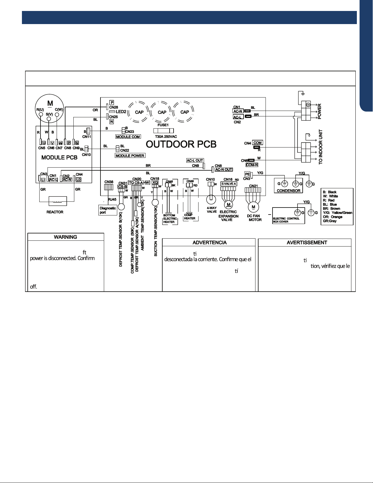
REFERENCE INFORMATION PAGE 63
ENGLISH
24K-36K
OUTDOOR UNIT WIRING DIAGRAM
COMPRESSOR
●
●
B
Y/G
123(C)
N
L
BL
BR
BR
BR
BL
Y/G
Y/G
0011520512
Electrical Shock Hazard
Capacitor retains charge a er
voltage at capacitor has dissipated
(<10V DC) with hand held voltmeter
before servicing. LED2 light
between CN24 and CN26 should be
Riesgo de Descarga Eléctrica
El capacitor re ene carga una vez
voltaje del capacitor se haya disipado (<10V
DC) apoyando la mano sobre el vol metro
antes de realizar el servicio técnico. La luz
LED2 que se encuentra entre CN24 y CN26
deberá estar apagada.
Risque de choc électrique
Le condensateur conserve sa charge après la
coupure de l’alimenta on électrique. Avant
de procéder à une répara
courant au condensateur s’est dissipé
(<10 VCC) à l’aide d’un voltmètre manuel. Le
voyant LED2 entre CN24 et CN26 doit être
éteint.
Outdoor Board Diagram
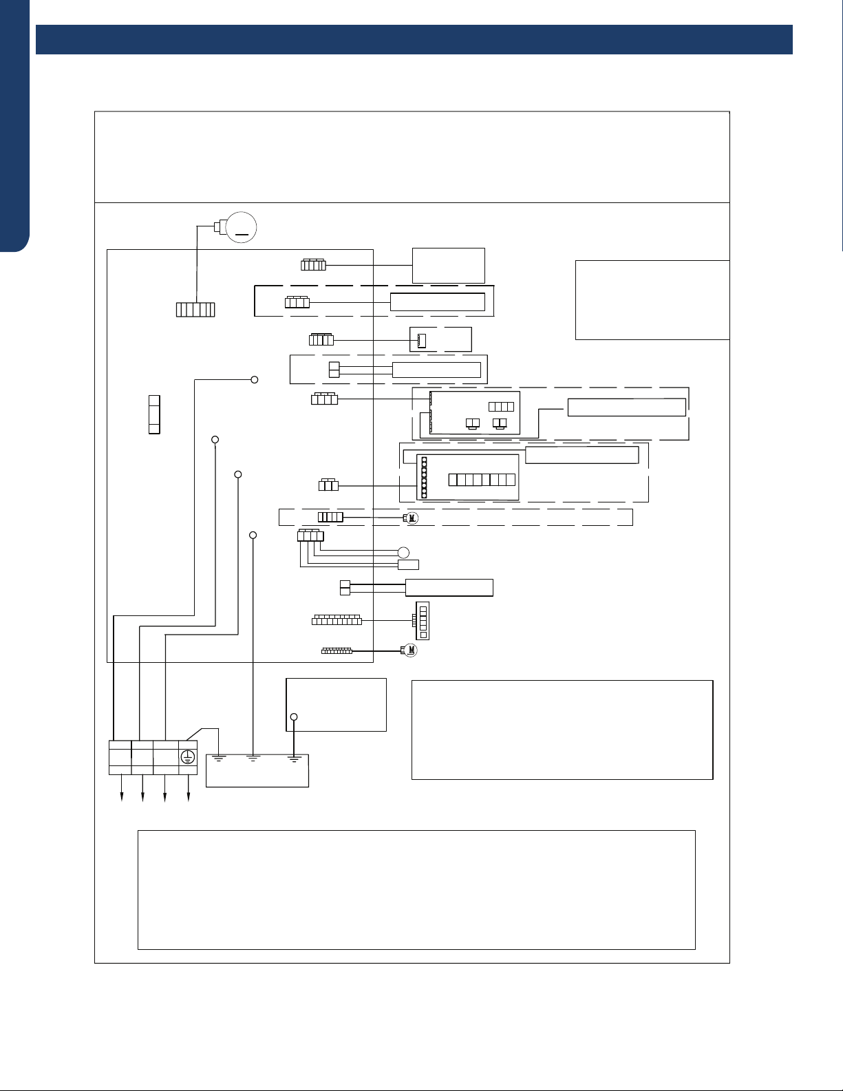
REFERENCE INFORMATION
PAGE 64
ENGLISH
24K
Indoor Board Diagram
R:Red
W:White
Y:Yellow
Y/G:Yellow/Green
B:Black
BR:Brown
BL:Blue
PIPING TEMP.SENSOR(10K)
AMBIENT TEMP.SENSOR(10K)
POWER BUTTON
INDOOR UNIT DIAGRAM
Notes:
1.The dotted parts are optional.
2.The two pins of CN51 should be shorted,
when the J6 is cuted off.
M
FUSE1
CN7
T3.15A/250VAC
TO OUTDOOR UNIT
1(N) (C)
3
(L)
2
WB
Y/G
GND
CN6
R
(L)
CN21
N
COMM
CN51
CN9
CN17
CN23'
CN35
CN34
ROOM CARD
CN5
DC FAN MOTOR
CN11'
DISPLAY BOARD
Model selection:
24K model-23 code - BM1 - 1 off 2 off
24K model-26 code - BM1 - 1 off 2 on
WIRED CONTROLLER
UP-DOWN STEPMOTOR
LEFT & RIGHT STEPMOTOR
WIFI
CN14
Notes:Before replacing the board,it
is necessary to ensure that the
machine is matched with the board
code
CN56 HUMAN SENSOR
CN38
CN27'
Y/G
GND
001152051
1A
WK-B
EVAPORATOR
ELECTRIC
CONTROL BOX
COVER
GND
Y/G
RJ45
Diagnostic
port
CN5
CN1
CN2
SW1
OFF OFF OFF OFF
CN3 CN4
CN2
CN6
CN4
CN3
CENTRALIZED CONTROLLER
SW2
OFF OFF OFF OFF OFF OFF OFF OFF
CN36
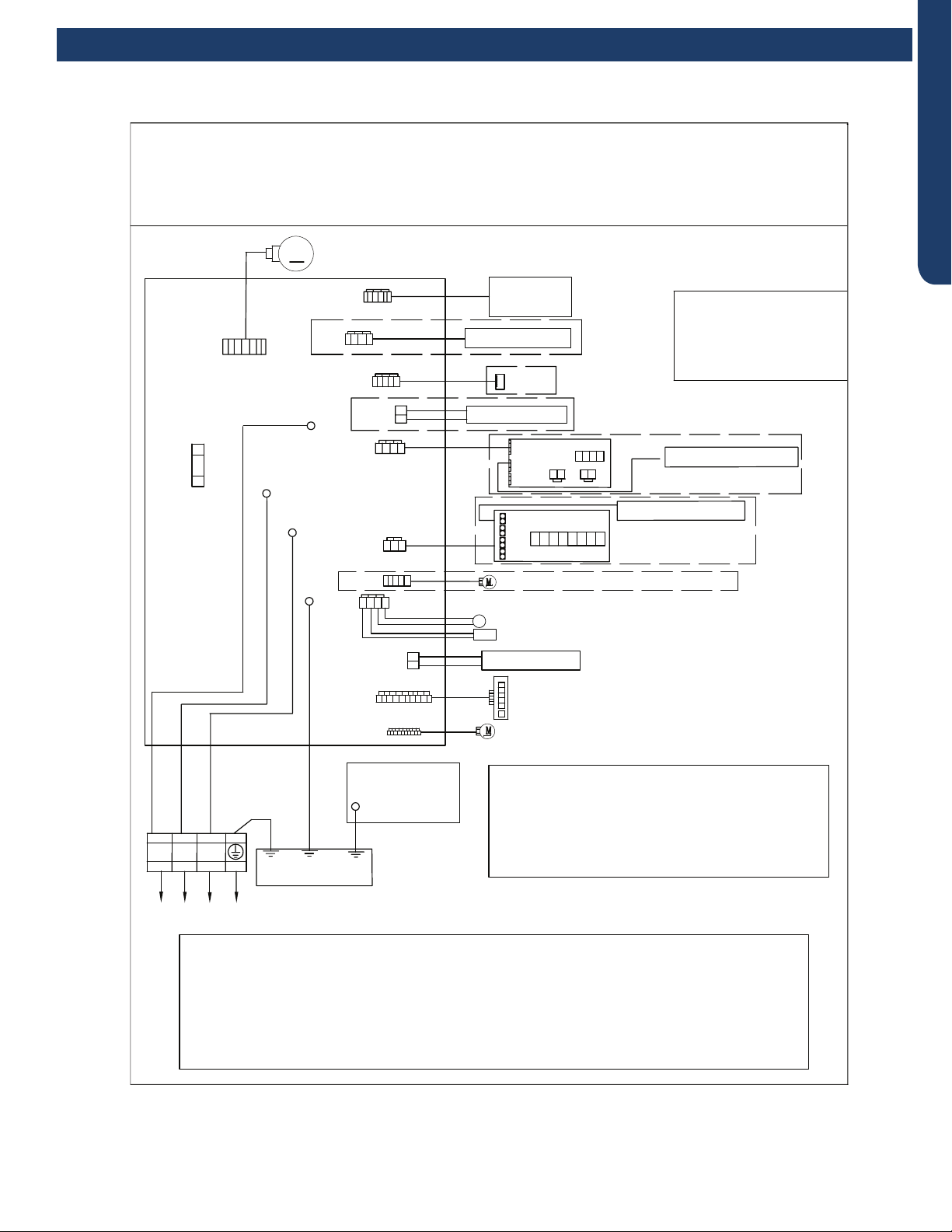
REFERENCE INFORMATION PAGE 65
ENGLISH
Indoor Board Diagram
30K-36K
R:Red
W:White
Y:Yellow
Y/G:Yellow/Green
B:Black
BR:Brown
BL:Blue
PIPING TEMP.SENSOR(10K)
AMBIENT TEMP.SENSOR(10K)
POWER BUTTON
INDOOR UNIT DIAGRAM
Notes:
1.The dotted parts are optional.
2.The two pins of CN51 should be shorted,
when the J6 is cuted off.
M
FUSE1
CN7
T3.15A/250VAC
TO OUTDOOR UNIT
1(N) (C)
3
(L)
2
WB
Y/G
GND
CN6
R
(L)
CN21
N
COMM
CN51
CN9
CN17
CN23'
CN35
CN34
ROOM CARD
CN5
DC FAN MOTOR
CN11'
DISPLAY BOARD
Model selection:
30K model-23 code - BM1 - 1 off 2 off
30K model-26 code - BM1 - 1 off 2 on
36K model-33 code - BM1 - 1 on 2 off
36K model-35 code - BM1 - 1 on 2 on
WIRED CONTROLLER
UP-DOWN STEPMOTOR
LEFT & RIGHT STEPMOTOR
WIFI
CN14
Notes:Before replacing the board,it
is necessary to ensure that the
machine is matched with the board
code
CN56 HUMAN SENSOR
CN38
CN27'
Y/G
GND
0011520511
WK-B
EVAPORATOR
ELECTRIC
CONTROL BOX
COVER
GND
Y/G
RJ45
Diagnostic
port
CN5
CN1
CN2
SW1
OFF OFF OFF OFF
CN3 CN4
CN2
CN6
CN4
CN3
CENTRALIZED CONTROLLER
SW2
OFF OFF OFF OFF OFF OFF OFF OFF
CN36

REFERENCE INFORMATION
PAGE 66
ENGLISH
Room and Coil Sensor Tables
Temp. °F Temp. °C Max.(KΩ) Normal(KΩ) Min.(KΩ) Tolerance (°C)
-22 -30 165.217 147.9497 132.3678 -1.94 1.75
-20.2 -29 155.5754 139.56 125.0806 -1.93 1.74
-18.4 -28 146.5609 131.7022 118.2434 -1.91 1.73
-16.6 -27 138.1285 124.3392 111.8256 -1.89 1.71
-14.8 -26 130.2371 117.4366 105.7989 -1.87 1.7
-13 -25 122.8484 110.9627 100.1367 -1.85 1.69
-11.2 -24 115.9272 104.8882 94.8149 -1.83 1.67
-9.4 -23 109.441 99.1858 89.8106 -1.81 1.66
-7.6 -22 103.3598 93.8305 85.1031 -1.8 1.64
-5.8 -21 97.6556 88.7989 80.6728 -1.78 1.63
-4 -20 92.3028 84.0695 76.5017 -1.76 1.62
-2.2 -19 87.2775 79.6222 72.5729 -1.74 1.6
-0.4 -18 82.5577 75.4384 68.871 -1.72 1.59
1.4 -17 78.123 71.501 65.3815 -1.7 1.57
3.2 -16 73.9543 67.7939 62.0907 -1.68 1.55
5-15 70.0342 64.3023 58.9863 -1.66 1.54
6.8 -14 66.3463 61.0123 56.0565 -1.64 1.52
8.6 -13 62.8755 57.911 53.2905 -1.62 1.51
10.4 -12 59.6076 54.9866 50.6781 -1.6 1.49
12.2 -11 56.5296 52.2278 48.2099 -1.58 1.47
14 -10 53.6294 49.6244 45.8771 -1.56 1.46
15.8 -9 50.8956 47.1666 43.6714 -1.54 1.44
17.6 -8 48.3178 44.8454 41.5851 -1.51 1.42
19.4 -7 45.886 42.6525 39.6112 -1.49 1.4
21.2 -6 43.5912 40.58 37.7429 -1.47 1.39
23 -5 41.4249 38.6207 35.9739 -1.45 1.37
24.8 -4 39.3792 36.7676 34.2983 -1.43 1.35
26.6 -3 37.4465 35.0144 32.7108 -1.41 1.33
28.4 -2 35.6202 33.3552 31.2062 -1.38 1.31
30.2 -1 33.8936 31.7844 29.7796 -1.36 1.29
32 0 32.2608 30.2968 28.4267 -1.34 1.28
33.8 1 30.7162 28.8875 27.1431 -1.32 1.26
35.6 229.2545 27.5519 25.925 -1.29 1.24
37.4 3 27.8708 26.2858 24.7686 -1.27 1.22
39.2 4 26.5605 25.0851 23.6704 -1.25 1.2
41 525.3193 23.9462 22.6273 -1.23 1.18
42.8 624.1432 22.8656 21.6361 -1.2 1.16
44.6 723.0284 21.8398 20.6939 -1.18 1.14
46.4 8 21.9714 20.8659 19.7982 -1.15 1.12
48.2 9 20.9688 19.9409 18.9463 -1.13 1.09
50 10 20.0176 19.0621 18.1358 -1.11 1.07
51.8 11 19.1149 18.227 17.3646 -1.08 1.05
53.6 12 18.258 17.4331 16.6305 -1.06 1.03
55.4 13 17.4442 16.6782 15.9315 -1.03 1.01
57.2 14 16.6711 15.9601 15.2657 -1.01 0.99
59 15 15.9366 15.277 14.6315 -0.98 0.96
60.8 16 15.2385 14.6268 14.0271 -0.96 0.94
R77° = 10KΩ±3%
B77°/122° = 3700K±3%

REFERENCE INFORMATION PAGE 67
ENGLISH
Temp. °F Temp. °C Max.(KΩ) Normal(KΩ) Min.(KΩ) Tolerance (°C)
62.6 17 14.5748 14.0079 13.451 -0.93 0.92
64.4 18 13.9436 13.4185 12.9017 -0.91 0.9
66.2 19 13.3431 12.8572 12.3778 -0.88 0.87
68 20 12.7718 12.3223 11.878 -0.86 0.85
69.8 21 12.228 11.8126 11.4011 -0.83 0.83
71.6 22 11.7102 11.3267 10.9459 -0.81 0.8
73.4 23 11.2172 10.8634 10.5114 -0.78 0.78
75.2 24 10.7475 10.4216 10.0964 -0.75 0.75
77 25 10.3 10.0 9.7 -0.75 0.75
78.8 26 9.8975 9.5974 9.298 -0.76 0.76
80.6 27 9.5129 9.2132 8.9148 -0.8 0.8
82.4 28 9.1454 8.8465 8.5496 -0.84 0.83
84.2 29 8.7942 8.4964 8.2013 -0.87 0.86
86 30 8.4583 8.1621 7.8691 -0.91 0.9
87.8 31 8.1371 7.8428 7.5522 -0.95 0.93
89.6 32 7.8299 7.5377 7.2498 -0.98 0.97
91.4 33 7.5359 7.2461 6.9611 -1.02 1
93.2 34 7.2546 6.9673 6.6854 -1.06 1.04
95 35 6.9852 6.7008 6.4222 -1.1 1.07
96.8 36 6.7273 6.4459 6.1707 -1.13 1.11
98.6 37 6.4803 6.2021 5.9304 -1.17 1.14
100.4 38 6.2437 5.9687 5.7007 -1.21 1.18
102.2 39 6.017 5.7454 5.4812 -1.25 1.22
104 40 5.7997 5.5316 5.2712 -1.29 1.25
105.8 41 5.5914 5.3269 5.0704 -1.33 1.29
107.6 42 5.3916 5.1308 4.8783 -1.37 1.33
109.4 43 5.2001 4.943 4.6944 -1.41 1.36
111.2 44 5.0163 4.763 4.5185 -1.45 1.4
113 45 4.84 4.5905 4.35 -1.49 1.44
114.8 46 4.6708 4.4252 4.1887 -1.53 1.47
116.6 47 4.5083 4.2666 4.0342 -1.57 1.51
118.4 48 4.3524 4.1145 3.8862 -1.61 1.55
120.2 49 4.2026 3.9686 3.7443 -1.65 1.59
122 50 4.0588 3.8287 3.6084 -1.7 1.62
123.8 51 3.9206 3.6943 3.478 -1.74 1.66
125.6 52 3.7878 3.5654 3.3531 -1.78 1.7
127.4 53 3.6601 3.4416 3.2332 -1.82 1.74
129.2 54 3.5374 3.3227 3.1183 -1.87 1.78
131 55 3.4195 3.2085 3.0079 -1.91 1.82
132.8 56 3.306 3.0989 2.9021 -1.95 1.85
134.6 57 3.1969 2.9935 2.8005 -2 1.89
136.4 58 3.0919 2.8922 2.7029 -2.04 1.93
138.2 59 2.9909 2.7948 2.6092 -2.08 1.97
140 60 2.8936 2.7012 2.5193 -2.13 2.01
141.8 61 2.8 2.6112 2.4328 -2.17 2.05
143.6 62 2.7099 2.5246 2.3498 -2.22 2.09
145.4 63 2.6232 2.4413 2.27 -2.26 2.13
147.2 64 2.5396 2.3611 2.1932 -2.31 2.17
Room and Coil Sensor Tables
REFERENCE INFORMATION
PAGE 68
ENGLISH
Temp. °F Temp. °C Max.(KΩ) Normal(KΩ) Min.(KΩ) Tolerance (°C)
149 65 2.4591 2.284 2.1195 -2.36 2.21
150.8 66 2.3815 2.2098 2.0486 -2.4 2.25
152.6 67 2.3068 2.1383 1.9803 -2.45 2.29
154.4 68 2.2347 2.0695 1.9147 -2.49 2.34
156.2 69 2.1652 2.0032 1.8516 -2.54 2.38
158 70 2.0983 1.9393 1.7908 -2.59 2.42
159.8 71 2.0337 1.8778 1.7324 -2.63 2.46
161.6 72 1.9714 1.8186 1.6761 -2.68 2.5
163.4 73 1.9113 1.7614 1.6219 -2.73 2.54
165.2 74 1.8533 1.7064 1.5697 -2.78 2.58
167 75 1.7974 1.6533 1.5194 -2.83 2.63
168.8 76 1.7434 1.6021 1.471 -2.88 2.67
170.6 77 1.6913 1.5528 1.4243 -2.92 2.71
172.4 78 1.6409 1.5051 1.3794 -2.97 2.75
174.2 79 1.5923 1.4592 1.336 -3.02 2.8
176 80 1.5454 1.4149 1.2942 -3.07 2.84
177.8 81 1.5 1.3721 1.254 -3.12 2.88
179.6 82 1.4562 1.3308 1.2151 -3.17 2.93
181.4 83 1.4139 1.291 1.1776 -3.22 2.97
183.2 84 1.373 1.2525 1.1415 -3.27 3.01
185 85 1.3335 1.2153 1.1066 -3.32 3.06
186.8 86 1.2953 1.1794 1.073 -3.38 3.1
188.6 87 1.2583 1.1448 1.0405 -3.43 3.15
190.4 88 1.2226 1.1113 1.0092 -3.48 3.19
192.2 89 1.188 1.0789 0.9789 -3.53 3.24
194 90 1.1546 1.0476 0.9497 -3.58 3.28
195.8 91 1.1223 1.0174 0.9215 -3.64 3.33
197.6 92 1.091 0.9882 0.8942 -3.69 3.37
199.4 93 1.0607 0.9599 0.8679 -3.74 3.42
201.2 94 1.0314 0.9326 0.8424 -3.8 3.46
203 95 1.003 0.9061 0.8179 -3.85 3.51
204.8 96 0.9756 0.8806 0.7941 -3.9 3.55
206.6 97 0.949 0.8558 0.7711 -3.96 3.6
208.4 98 0.9232 0.8319 0.7489 -4.01 3.64
210.2 99 0.8983 0.8088 0.7275 -4.07 3.69
212 100 0.8741 0.7863 0.7067 -4.12 3.74
213.8 101 0.8507 0.7646 0.6867 -4.18 3.78
215.6 102 0.8281 0.7436 0.6672 -4.23 3.83
217.4 103 0.8061 0.7233 0.6484 -4.29 3.88
219.2 104 0.7848 0.7036 0.6303 -4.34 3.92
221 105 0.7641 0.6845 0.6127 -4.4 3.97
222.8 106 0.7441 0.6661 0.5957 -4.46 4.02
224.6 107 0.7247 0.6482 0.5792 -4.51 4.07
226.4 108 0.7059 0.6308 0.5632 -4.57 4.12
228.2 109 0.6877 0.614 0.5478 -4.63 4.16
230 110 0.67 0.5977 0.5328 -4.69 4.21
231.8 111 0.6528 0.582 0.5183 -4.74 4.26
233.6 112 0.6361 0.5667 0.5043 -4.8 4.31
Room and Coil Sensor Tables
REFERENCE INFORMATION PAGE 69
ENGLISH
Temp. °F Temp. °C Max.(KΩ) Normal(KΩ) Min.(KΩ) Tolerance (°C)
235.4 113 0.62 0.5518 0.4907 -4.86 4.36
237.2 114 0.6043 0.5374 0.4775 -4.92 4.41
239 115 0.5891 0.5235 0.4648 -4.98 4.45
240.8 116 0.5743 0.51 0.4524 -5.04 4.5
242.6 117 0.56 0.4968 0.4404 -5.1 4.55
244.4 118 0.546 0.4841 0.4288 -5.16 4.6
246.2 119 0.5325 0.4717 0.4175 -5.22 4.65
248 120 0.5194 0.4597 0.4066 -5.28 4.7
Temp. °F Temp. °C Max.(KΩ) Normal(KΩ) Min.(KΩ) Tolerance (°C)
-22 -30 165.2170 147.9497 132.3678 -1.94 1.75
-20 -29 155.5754 139.5600 125.0806 -1.93 1.74
-18 -28 146.5609 131.7022 118.2434 -1.91 1.73
-17 -27 138.1285 124.3392 111.8256 -1.89 1.71
-15 -26 130.2371 117.4366 105.7989 -1.87 1.70
-13 -25 122.8484 110.9627 100.1367 -1.85 1.69
-11 -24 115.9272 104.8882 94.8149 -1.83 1.67
-9 -23 109.4410 99.1858 89.8106 -1.81 1.66
-8 -22 103.3598 93.8305 85.1031 -1.80 1.64
-6 -21 97.6556 88.7989 80.6728 -1.78 1.63
-4 -20 92.3028 84.0695 76.5017 -1.76 1.62
-2 -19 87.2775 79.6222 72.5729 -1.74 1.60
0 -18 82.5577 75.4384 68.8710 -1.72 1.59
1 -17 78.1230 71.5010 65.3815 -1.70 1.57
3 -16 73.9543 67.7939 62.0907 -1.68 1.55
5-15 70.0342 64.3023 58.9863 -1.66 1.54
7-14 66.3463 61.0123 56.0565 -1.64 1.52
9 -13 62.8755 57.9110 53.2905 -1.62 1.51
10 -12 59.6076 54.9866 50.6781 -1.60 1.49
12 -11 56.5296 52.2278 48.2099 -1.58 1.47
14 -10 53.6294 49.6244 45.8771 -1.56 1.46
16 -9 50.8956 47.1666 43.6714 -1.54 1.44
18 -8 48.3178 44.8454 41.5851 -1.51 1.42
19 -7 45.8860 42.6525 39.6112 -1.49 1.40
21 -6 43.5912 40.5800 37.7429 -1.47 1.39
23 -5 41.4249 38.6207 35.9739 -1.45 1.37
25 -4 39.3792 36.7676 34.2983 -1.43 1.35
27 -3 37.4465 35.0144 32.7108 -1.41 1.33
28 -2 35.6202 33.3552 31.2062 -1.38 1.31
30 -1 33.8936 31.7844 29.7796 -1.36 1.29
32 0 32.2608 30.2968 28.4267 -1.34 1.28
34 1 30.7162 28.8875 27.1431 -1.32 1.26
36 229.2545 27.5519 25.9250 -1.29 1.24
37 3 27.8708 26.2858 24.7686 -1.27 1.22
39 4 26.5605 25.0851 23.6704 -1.25 1.20
41 525.3193 23.9462 22.6273 -1.23 1.18
43 624.1432 22.8656 21.6361 -1.20 1.16
Room and Coil Sensor Tables
Ambient, Defrost, Pipe Sensor Tables

REFERENCE INFORMATION
PAGE 70
ENGLISH
Temp. °F Temp. °C Max.(KΩ) Normal(KΩ) Min.(KΩ) Tolerance (°C)
45 723.0284 21.8398 20.6939 -1.18 1.14
46 8 21.9714 20.8659 19.7982 -1.15 1.12
48 9 20.9688 19.9409 18.9463 -1.13 1.09
50 10 20.0176 19.0621 18.1358 -1.11 1.07
52 11 19.1149 18.2270 17.3646 -1.08 1.05
54 12 18.2580 17.4331 16.6305 -1.06 1.03
55 13 17.4442 16.6782 15.9315 -1.03 1.01
57 14 16.6711 15.9601 15.2657 -1.01 0.99
59 15 15.9366 15.2770 14.6315 -0.98 0.96
61 16 15.2385 14.6268 14.0271 -0.96 0.94
63 17 14.5748 14.0079 13.4510 -0.93 0.92
64 18 13.9436 13.4185 12.9017 -0.91 0.90
66 19 13.3431 12.8572 12.3778 -0.88 0.87
68 20 12.7718 12.3223 11.8780 -0.86 0.85
70 21 12.2280 11.8126 11.4011 -0.83 0.83
72 22 11.7102 11.3267 10.9459 -0.81 0.80
73 23 11.2172 10.8634 10.5114 -0.78 0.78
75 24 10.7475 10.4216 10.0964 -0.75 0.75
77 25 10.3000 10.0000 9.7000 -0.75 0.75
79 26 9.8975 9.5974 9.2980 -0.76 0.76
81 27 9.5129 9.2132 8.9148 -0.80 0.80
82 28 9.1454 8.8465 8.5496 -0.84 0.83
84 29 8.7942 8.4964 8.2013 -0.87 0.86
86 30 8.4583 8.1621 7.8691 -0.91 0.90
88 31 8.1371 7.8428 7.5522 -0.95 0.93
90 32 7.8299 7.5377 7.2498 -0.98 0.97
91 33 7.5359 7.2461 6.9611 -1.02 1.00
93 34 7.2546 6.9673 6.6854 -1.06 1.04
95 35 6.9852 6.7008 6.4222 -1.10 1.07
97 36 6.7273 6.4459 6.1707 -1.13 1.11
99 37 6.4803 6.2021 5.9304 -1.17 1.14
100 38 6.2437 5.9687 5.7007 -1.21 1.18
102 39 6.0170 5.7454 5.4812 -1.25 1.22
104 40 5.7997 5.5316 5.2712 -1.29 1.25
106 41 5.5914 5.3269 5.0704 -1.33 1.29
108 42 5.3916 5.1308 4.8783 -1.37 1.33
109 43 5.2001 4.9430 4.6944 -1.41 1.36
111 44 5.0163 4.7630 4.5185 -1.45 1.40
113 45 4.8400 4.5905 4.3500 -1.49 1.44
115 46 4.6708 4.4252 4.1887 -1.53 1.47
117 47 4.5083 4.2666 4.0342 -1.57 1.51
118 48 4.3524 4.1145 3.8862 -1.61 1.55
120 49 4.2026 3.9686 3.7443 -1.65 1.59
122 50 4.0588 3.8287 3.6084 -1.70 1.62
124 51 3.9206 3.6943 3.4780 -1.74 1.66
126 52 3.7878 3.5654 3.3531 -1.78 1.70
127 53 3.6601 3.4416 3.2332 -1.82 1.74
129 54 3.5374 3.3227 3.1183 -1.87 1.78
Ambient, Defrost, Pipe Sensor Tables

REFERENCE INFORMATION PAGE 71
ENGLISH
Temp. °F Temp. °C Max.(KΩ) Normal(KΩ) Min.(KΩ) Tolerance (°C)
131 55 3.4195 3.2085 3.0079 -1.91 1.82
133 56 3.3060 3.0989 2.9021 -1.95 1.85
135 57 3.1969 2.9935 2.8005 -2.00 1.89
136 58 3.0919 2.8922 2.7029 -2.04 1.93
138 59 2.9909 2.7948 2.6092 -2.08 1.97
140 60 2.8936 2.7012 2.5193 -2.13 2.01
142 61 2.8000 2.6112 2.4328 -2.17 2.05
144 62 2.7099 2.5246 2.3498 -2.22 2.09
145 63 2.6232 2.4413 2.2700 -2.26 2.13
147 64 2.5396 2.3611 2.1932 -2.31 2.17
149 65 2.4591 2.2840 2.1195 -2.36 2.21
151 66 2.3815 2.2098 2.0486 -2.40 2.25
153 67 2.3068 2.1383 1.9803 -2.45 2.29
154 68 2.2347 2.0695 1.9147 -2.49 2.34
156 69 2.1652 2.0032 1.8516 -2.54 2.38
158 70 2.0983 1.9393 1.7908 -2.59 2.42
160 71 2.0337 1.8778 1.7324 -2.63 2.46
162 72 1.9714 1.8186 1.6761 -2.68 2.50
163 73 1.9113 1.7614 1.6219 -2.73 2.54
165 74 1.8533 1.7064 1.5697 -2.78 2.58
167 75 1.7974 1.6533 1.5194 -2.83 2.63
169 76 1.7434 1.6021 1.4710 -2.88 2.67
171 77 1.6913 1.5528 1.4243 -2.92 2.71
172 78 1.6409 1.5051 1.3794 -2.97 2.75
174 79 1.5923 1.4592 1.3360 -3.02 2.80
176 80 1.5454 1.4149 1.2942 -3.07 2.84
178 81 1.5000 1.3721 1.2540 -3.12 2.88
180 82 1.4562 1.3308 1.2151 -3.17 2.93
181 83 1.4139 1.2910 1.1776 -3.22 2.97
183 84 1.3730 1.2525 1.1415 -3.27 3.01
185 85 1.3335 1.2153 1.1066 -3.32 3.06
187 86 1.2953 1.1794 1.0730 -3.38 3.10
189 87 1.2583 1.1448 1.0405 -3.43 3.15
190 88 1.2226 1.1113 1.0092 -3.48 3.19
192 89 1.1880 1.0789 0.9789 -3.53 3.24
194 90 1.1546 1.0476 0.9497 -3.58 3.28
196 91 1.1223 1.0174 0.9215 -3.64 3.33
198 92 1.0910 0.9882 0.8942 -3.69 3.37
199 93 1.0607 0.9599 0.8679 -3.74 3.42
201 94 1.0314 0.9326 0.8424 -3.80 3.46
203 95 1.0030 0.9061 0.8179 -3.85 3.51
205 96 0.9756 0.8806 0.7941 -3.90 3.55
207 97 0.9490 0.8558 0.7711 -3.96 3.60
208 98 0.9232 0.8319 0.7489 -4.01 3.64
210 99 0.8983 0.8088 0.7275 -4.07 3.69
212 100 0.8741 0.7863 0.7067 -4.12 3.74
214 101 0.8507 0.7646 0.6867 -4.18 3.78
216 102 0.8281 0.7436 0.6672 -4.23 3.83
Ambient, Defrost, Pipe Sensor Tables
REFERENCE INFORMATION
PAGE 72
ENGLISH
Temp. °F Temp. °C Max.(KΩ) Normal(KΩ) Min.(KΩ) Tolerance (°C)
217 103 0.8061 0.7233 0.6484 -4.29 3.88
219 104 0.7848 0.7036 0.6303 -4.34 3.92
221 105 0.7641 0.6845 0.6127 -4.40 3.97
223 106 0.7441 0.6661 0.5957 -4.46 4.02
225 107 0.7247 0.6482 0.5792 -4.51 4.07
226 108 0.7059 0.6308 0.5632 -4.57 4.12
228 109 0.6877 0.6140 0.5478 -4.63 4.16
230 110 0.6700 0.5977 0.5328 -4.69 4.21
232 111 0.6528 0.5820 0.5183 -4.74 4.26
234 112 0.6361 0.5667 0.5043 -4.80 4.31
235 113 0.6200 0.5518 0.4907 -4.86 4.36
237 114 0.6043 0.5374 0.4775 -4.92 4.41
239 115 0.5891 0.5235 0.4648 -4.98 4.45
241 116 0.5743 0.5100 0.4524 -5.04 4.50
243 117 0.5600 0.4968 0.4404 -5.10 4.55
244 118 0.5460 0.4841 0.4288 -5.16 4.60
246 119 0.5325 0.4717 0.4175 -5.22 4.65
248 120 0.5194 0.4597 0.4066 -5.28 4.70
Temp.(°F) Temp.(°C) Max.(KΩ) Normal(KΩ) Min.(KΩ) Tolerance
-22 -30 14646.0505 12061.7438 9924.4999 -2.96 2.45
-20.2 -29 13654.1707 11267.873 9290.2526 -2.95 2.44
-18.4 -28 12735.8378 10531.3695 8700.6388 -2.93 2.44
-16.6 -27 11885.1336 9847.724 8152.2338 -2.92 2.43
-14.8 -26 11096.6531 9212.8101 7641.8972 -2.91 2.42
-13 -25 10365.4565 8622.8491 7166.7474 -2.9 2.42
-11.2 -24 9687.027 8074.3787 6724.1389 -2.88 2.41
-9.4 -23 9057.2314 7564.2244 6311.6413 -2.87 2.41
-7.6 -22 8472.2852 7089.4741 5927.0206 -2.86 2.4
-5.8 -21 7928.7217 6647.4547 5568.2222 -2.84 2.39
-4 -20 7423.3626 6235.7109 5233.3554 -2.83 2.39
-2.2 -19 6953.293 5851.9864 4920.6791 -2.82 2.38
-0.4 -18 6515.8375 5494.2064 4628.5894 -2.8 2.37
1.4 -17 6108.5393 5160.4621 4355.6078 -2.79 2.37
3.2 -16 5729.1413 4848.9963 4100.3708 -2.77 2.36
5-15 5375.5683 4558.1906 3861.6201 -2.76 2.35
6.8 -14 5045.9114 4286.5535 3638.1938 -2.75 2.34
8.6 -13 4738.4141 4032.7098 3429.0191 -2.73 2.34
10.4 -12 4451.4586 3795.391 3233.1039 -2.72 2.33
12.2 -11 4183.5548 3573.426 3049.5312 -2.7 2.32
14 -10 3933.3289 3365.7336 2877.4527 -2.69 2.31
15.8 -9 3699.5139 3171.3148 2716.0828 -2.67 2.3
17.6 -8 3480.9407 2989.246 2564.6945 -2.66 2.29
19.4 -7 3276.5302 2818.6731 2422.6139 -2.64 2.28
21.2 -6 3085.2854 2658.8058 2289.2164 -2.63 2.28
23 -5 2906.2851 2508.9126 2163.923 -2.61 2.27
R176° = 50KΩ±3%
B77°/176° = 4450K±3%
Ambient, Defrost, Pipe Sensor Tables
Discharge Sensor Tables

REFERENCE INFORMATION PAGE 73
ENGLISH
Temp.(°F) Temp.(°C) Max.(KΩ) Normal(KΩ) Min.(KΩ) Tolerance
24.8 -4 2738.6777 2368.3158 2046.1961 -2.6 2.26
26.6 -3 2581.6752 2236.3876 1935.5371 -2.58 2.25
28.4 -2 2434.5487 2112.5459 1831.4826 -2.56 2.24
30.2 -1 2296.623 1996.2509 1733.6024 -2.55 2.23
32 0 2167.273 1887.0018 1641.4966 -2.53 2.22
33.8 1 2045.9191 1784.3336 1554.7931 -2.52 2.21
35.6 21932.0242 1687.8144 1473.146 -2.5 2.2
37.4 3 1825.0899 1597.0431 1396.2333 -2.48 2.19
39.2 4 1724.654 1511.6468 1323.7551 -2.47 2.17
41 51630.287 1431.2787 1255.4324 -2.45 2.16
42.8 61541.5904 1355.6163 1191.0048 -2.43 2.15
44.6 71458.1938 1284.3593 1130.2298 -2.41 2.14
46.4 8 1379.7528 1217.2282 1072.8813 -2.4 2.13
48.2 9 1305.9472 1153.9626 1018.7481 -2.38 2.12
50 10 1236.4792 1094.32 967.6334 -2.36 2.11
51.8 11 1171.0715 1038.0743 919.3533 -2.35 2.09
53.6 12 1109.4661 985.0146 873.7359 -2.33 2.08
55.4 13 1051.4226 934.944 830.621 -2.31 2.07
57.2 14 996.7169 887.6792 789.8583 -2.29 2.06
59 15 945.1404 843.0486 751.3077 -2.27 2.04
60.8 16 896.4981 800.8922 714.838 -2.26 2.03
62.6 17 850.6086 761.0603 680.3265 -2.24 2.02
64.4 18 807.3024 723.4134 647.658 -2.22 2
66.2 19 766.4212 687.8205 616.7252 -2.2 1.99
68 20 727.8172 654.1596 587.4271 -2.18 1.98
69.8 21 691.3524 622.3161 559.6694 -2.16 1.96
71.6 22 656.8979 592.1831 533.3634 -2.14 1.95
73.4 23 624.3328 563.6604 508.4261 -2.12 1.93
75.2 24 593.5446 536.654 484.7796 -2.1 1.92
77 25 564.4275 511.076 462.351 -2.09 1.9
78.8 26 536.9865 486.9352 441.1516 -2.07 1.89
80.6 27 511.0105 464.05 421.0258 -2.05 1.87
82.4 28 486.4151 442.3499 401.9146 -2.03 1.86
84.2 29 463.1208 421.7683 383.7626 -2.01 1.84
86 30 441.0535 402.243 366.5175 -1.99 1.83
87.8 31 420.1431 383.7151 350.1301 -1.97 1.81
89.6 32 400.3242 366.1295 334.5542 -1.95 1.8
91.4 33 381.535 349.4341 319.746 -1.93 1.78
93.2 34 363.7176 333.5801 305.6645 -1.9 1.76
95 35 346.8176 318.5216 292.2709 -1.88 1.75
96.8 36 330.7839 304.2151 279.5286 -1.86 1.73
98.6 37 315.5682 290.6199 267.4031 -1.84 1.71
100.4 38 301.1254 277.6976 255.862 -1.82 1.7
102.2 39 287.4128 265.4119 244.8745 -1.8 1.68
104 40 274.3905 253.7288 234.4118 -1.78 1.66
105.8 41 262.0206 242.6161 224.4465 -1.76 1.64
107.6 42 250.2676 232.0436 214.9529 -1.74 1.63
109.4 43 239.0983 221.9825 205.9065 -1.71 1.61
111.2 44 228.4809 212.406 197.2844 -1.69 1.59
Discharge Sensor Tables

REFERENCE INFORMATION
PAGE 74
ENGLISH
Temp.(°F) Temp.(°C) Max.(KΩ) Normal(KΩ) Min.(KΩ) Tolerance
113 45 218.386 203.2887 189.0648 -1.67 1.57
114.8 46 208.7855 194.6066 181.2273 -1.65 1.55
116.6 47 199.6531 186.3369 173.7524 -1.63 1.54
118.4 48 190.9639 178.4584 166.6217 -1.6 1.52
120.2 49 182.6945 170.9508 159.8181 -1.58 1.5
122 50 174.8228 163.7951 153.3249 -1.56 1.48
123.8 51 167.328 156.9733 147.1268 -1.53 1.46
125.6 52 160.1904 150.4683 141.209 -1.51 1.44
127.4 53 153.3914 144.2641 135.5577 -1.49 1.42
129.2 54 146.9136 138.3454 130.1598 -1.47 1.4
131 55 140.7403 132.698 125.0027 -1.44 1.38
132.8 56 134.8559 127.3081 120.0746 -1.42 1.36
134.6 57 129.2457 122.163 115.3645 -1.4 1.34
136.4 58 123.8956 117.2504 110.8618 -1.37 1.32
138.2 59 118.7926 112.5589 106.5564 -1.35 1.3
140 60 113.9241 108.0776 102.4388 -1.32 1.28
141.8 61 109.2784 103.7961 98.5 -1.3 1.26
143.6 62 104.8443 99.7046 94.7315 -1.28 1.23
145.4 63 100.6112 95.7939 91.1253 -1.25 1.21
147.2 64 96.5692 92.0553 87.6735 -1.23 1.19
149 65 92.7088 88.4805 84.369 -1.2 1.17
150.8 66 89.0211 85.0614 81.2048 -1.18 1.15
152.6 67 85.4976 81.7908 78.1744 -1.15 1.12
154.4 68 82.1303 78.6615 75.2715 -1.13 1.1
156.2 69 78.9116 75.6668 72.4902 -1.1 1.08
158 70 75.8343 72.8004 69.8249 -1.08 1.06
159.8 71 72.8916 70.0561 67.2703 -1.05 1.03
161.6 72 70.077 67.4283 64.8213 -1.03 1.01
163.4 73 67.3844 64.9115 62.4731 -1 0.99
165.2 74 64.808 62.5006 60.2211 -0.98 0.96
167 75 62.3423 60.1906 58.0609 -0.95 0.94
168.8 76 59.9821 57.977 55.9885 -0.92 0.92
170.6 77 57.7223 55.8552 53.9998 -0.9 0.89
172.4 78 55.5583 53.821 52.0912 -0.87 0.87
174.2 79 53.4856 51.8706 50.2591 -0.85 0.84
176 80 51.5 50.0 48.5 -0.85 0.84
177.8 81 49.7063 48.2057 46.7083 -0.85 0.85
179.6 82 47.9835 46.4842 44.9911 -0.89 0.89
181.4 83 46.3286 44.8323 43.3452 -0.93 0.92
183.2 84 44.7385 43.2468 41.7672 -0.96 0.95
185 85 43.2105 41.7248 40.254 -1 0.99
186.8 86 41.7386 40.2604 38.7996 -1.03 1.02
188.6 87 40.3241 38.8545 37.4048 -1.07 1.06
190.4 88 38.9643 37.5045 36.0668 -1.11 1.09
192.2 89 37.6569 36.2078 34.7831 -1.14 1.13
194 90 36.3996 34.9622 33.5513 -1.18 1.16
195.8 91 35.1903 33.7653 32.3689 -1.22 1.19
197.6 92 34.0269 32.6151 31.2338 -1.26 1.23
199.4 93 32.9075 31.5096 30.1438 -1.3 1.27
Discharge Sensor Tables
REFERENCE INFORMATION PAGE 75
ENGLISH
Temp.(°F) Temp.(°C) Max.(KΩ) Normal(KΩ) Min.(KΩ) Tolerance
201.2 94 31.8302 30.4467 29.097 -1.33 1.3
203 95 30.7933 29.4246 28.0915 -1.37 1.34
204.8 96 29.795 28.4417 27.1254 -1.41 1.37
206.6 97 28.8337 27.4961 26.197 -1.45 1.41
208.4 98 27.9078 26.5864 25.3048 -1.49 1.44
210.2 99 27.016 25.711 24.447 -1.53 1.48
212 100 26.1569 24.8685 23.6222 -1.57 1.52
213.8 101 25.329 24.0574 22.8291 -1.61 1.55
215.6 102 24.5311 23.2765 22.0662 -1.65 1.59
217.4 103 23.762 22.5245 21.3323 -1.69 1.63
219.2 104 23.0205 21.8002 20.6261 -1.73 1.66
221 105 22.3055 21.1025 19.9465 -1.77 1.7
222.8 106 21.6159 20.4303 19.2924 -1.81 1.74
224.6 107 20.9508 19.7825 18.6626 -1.85 1.77
226.4 108 20.3091 19.1582 18.0563 -1.89 1.81
228.2 109 19.6899 18.5564 17.4723 -1.93 1.85
230 110 19.0924 17.9761 16.9098 -1.98 1.89
231.8 111 18.5157 17.4166 16.368 -2.02 1.93
233.6 112 17.959 16.8769 15.8458 -2.06 1.96
235.4 113 17.4214 16.3564 15.3427 -2.1 2
237.2 114 16.9023 15.8542 14.8577 -2.15 2.04
239 115 16.401 15.3696 14.3902 -2.19 2.08
240.8 116 15.9167 14.902 13.9394 -2.23 2.12
242.6 117 15.4489 14.4506 13.5047 -2.27 2.16
244.4 118 14.9968 14.0149 13.0855 -2.32 2.19
246.2 119 14.5599 13.5942 12.6811 -2.36 2.23
248 120 14.1376 13.1879 12.2909 -2.41 2.27
249.8 121 13.7294 12.7955 11.9144 -2.45 2.31
251.6 122 13.3347 12.4165 11.551 -2.5 2.35
253.4 123 12.9531 12.0503 11.2003 -2.54 2.39
255.2 124 12.584 11.6965 10.8617 -2.58 2.43
257 125 12.227 11.3545 10.5348 -2.63 2.47
258.8 126 11.8817 11.024 10.2191 -2.68 2.51
260.6 127 11.5475 10.7046 9.9142 -2.72 2.55
262.4 128 11.2242 10.3957 9.6197 -2.77 2.59
264.2 129 10.9112 10.097 9.3352 -2.81 2.63
266 130 10.6084 9.8082 9.0602 -2.86 2.67
267.8 131 10.3151 9.5288 8.7945 -2.91 2.71
269.6 132 10.0312 9.2586 8.5378 -2.95 2.75
271.4 133 9.7563 8.9971 8.2895 -3 2.8
273.2 134 9.4901 8.7441 8.0495 -3.05 2.84
275 135 9.2322 8.4993 7.8175 -3.09 2.88
276.8 136 8.9824 8.2623 7.5931 -3.14 2.92
278.6 137 8.7404 8.0329 7.376 -3.19 2.96
280.4 138 8.5059 7.8108 7.166 -3.24 3
282.2 139 8.2787 7.5958 6.9629 -3.29 3.04
284 140 8.0584 7.3875 6.7664 -3.33 3.09
Discharge Sensor Tables

REFERENCE INFORMATION
PAGE 76
ENGLISH
DIP Switch Settings
[Thispageintentionallyleftblank.]

Haier America,
Wayne, NJ 07470
©2022 Haier America Trading, LLC.
Rev. Mar. 2022
Model #:
AW24TL2HFA
AW30TL2HFA
AW36TL2HFA
ASYW24TRDFA
ASYW30TRDFA
ASYW36TRDFA
1U24TL2HFA
1U3036TL2HFA
ASH124TRDFA
ASH3036TRDFA