
40KMC
/
38HDF
40KMQ
/
38QRF
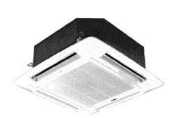
In—Ceiling
Cassette
Duct—Free
Split
System
Sizes
018
to
036
turn
to
the
experts
fF
Installation
Instructions
40KMC,
KMQ
Unit
38HDF/QRF
Unit
NOTE:
Read
the
entire
instruction
manual
before
starting
the
installation.
CA
UA
Le:
UNIT
OPERATION
AND
SAFETY
HAZARD
Failure
to
follow
this
warning
could
result
in
personal
injury
or
equipment
damage.
Puron
refrigerant
systems
operate
at
higher
pressures
than
standard
R-22
systems.
To
avoid
damage
to
the
unit
or
possible
personal
injury,
do
not
use
R-22
service
equipment
or
components
on
Puron
refrigerant
equipment.
SAFETY
CONSIDERATIONS
Improper
installation,
adjustment,
alteration,
service,
maintenance,
or
use
can
cause
explosion,
fire,
electrical
shock,
or
other
conditions
which
may
cause
death,
personal
injury,
or
property
damage.
Consult
a
qualified
installer,
service
agency,
or
your
distributor
or
branch
for
information
or
assistance.
The
qualified
installer
or
agency
must
use
factory-authorized
kits
or
accessories
when
modifying
this
product. Refer
to
the
individual
instructions
packaged
with
the
kits
or
accessories
when
installing.
Follow
all
safety
codes.
Wear
safety
glasses,
protective
clothing,
and
work
gloves.
Use
quenching
cloth
for
brazing
operations.
Have
fire
extinguisher
available.
Read
these
instructions
thoroughly
and
follow
all
warnings
or
cautions
included
in
literature
and
attached
to
the
unit.
Consult
local
building
codes
and
current
editions
of
the
National
Electrical
Code
(
NEC
)
NFPA
70.
In
Canada,
refer
to
current
editions
of
the
Canadian
electrical
code
CSA
22.1.
Recognize
safety
information.
This
is
the
safety-alert
symbol
A
When
you
see
this
symbol
on
the
unit
and
in
instructions
or
manuals,
be
alert
to
the
potential
for
personal
injury.
Understand
these
signal
words;
DANGER,
WARNING,
and
CAUTION.
These
words
are
used
with
the
safety-alert
symbol.
DANGER
identifies
the
most
serious
hazards
which
will
result
in
severe
personal
injury
or
death.
WARNING
signifies
hazards
which
could
result
in
personal
injury
or
death.
CAUTION
is
used
to
identify
unsafe
practices
which
would
result
in
minor
personal
injury
or
product
and
property
damage.
NOTE
is
used
to
highlight
suggestions
which
will
result
in
enhanced
installation,
reliability,
or
operation.
ELECTRICAL
SHOCK
HAZARD
Failure
to
follow
this
warning
could
result
in
personal
injury
or
death.
Before
installing,
modifying,
or
servicing
system,
main
electrical
disconnect
switch
must
be
in
the
OFF
position.
There
may
be
more
than
1
disconnect
switch.
Lock
out
and
tag
switch
with
a
suitable
warning
label.
PERSONAL
INJURY
AND
EQUIPMENT
DAMAGE
HAZARD
Failure
to
follow
this
caution
may
result
in
personal
injury
and
/
or
equipment
damage.
DO
NOT
operate
the
unit
without
a
filter
or
with
grille
removed.
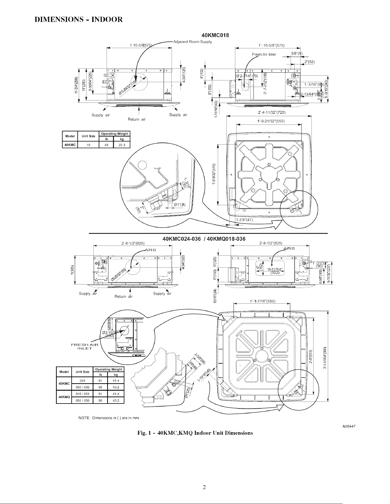
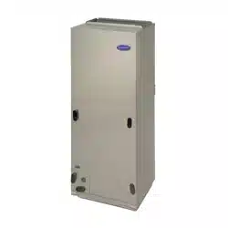
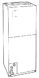
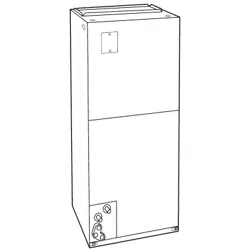
DIMENSIONS
-
INDOOR
40KMC018
Adjacent
Room
Supply
10-5/IRST5}
al
@
=
a
es
«
&
g
g|
.|2
MWe
=
=
°|
=|
6
Net
=P
abe
Ta
=
=
‘
—
©
Supply
air
Supply
air
=
_
2'-4-11/32"(720)
_
Return
air
1'-9-21/32"(650)
Model
|
Unit
Size
Operating
Weight
Ib
kg
40KMC
18
49
22.3
FRESH
AiR
41-8
9/32"(515)
Return
40KMC024-036
/
40KMQ018-036
3-1-5
1164"(960)
INLET
Operating
Weight
Model
|
Unit
Size
PPS
Ib
kg
024
91
414
40KMC
030
/
036
95
43.2
018/024
91
414
40KMQ
030
/
036
95
43.2
NOTE:
Dimensions
in
()
are
in
mm.
A08447
Fig.
1
-
40KMC,KMQ
Indoor
Unit
Dimensions
2
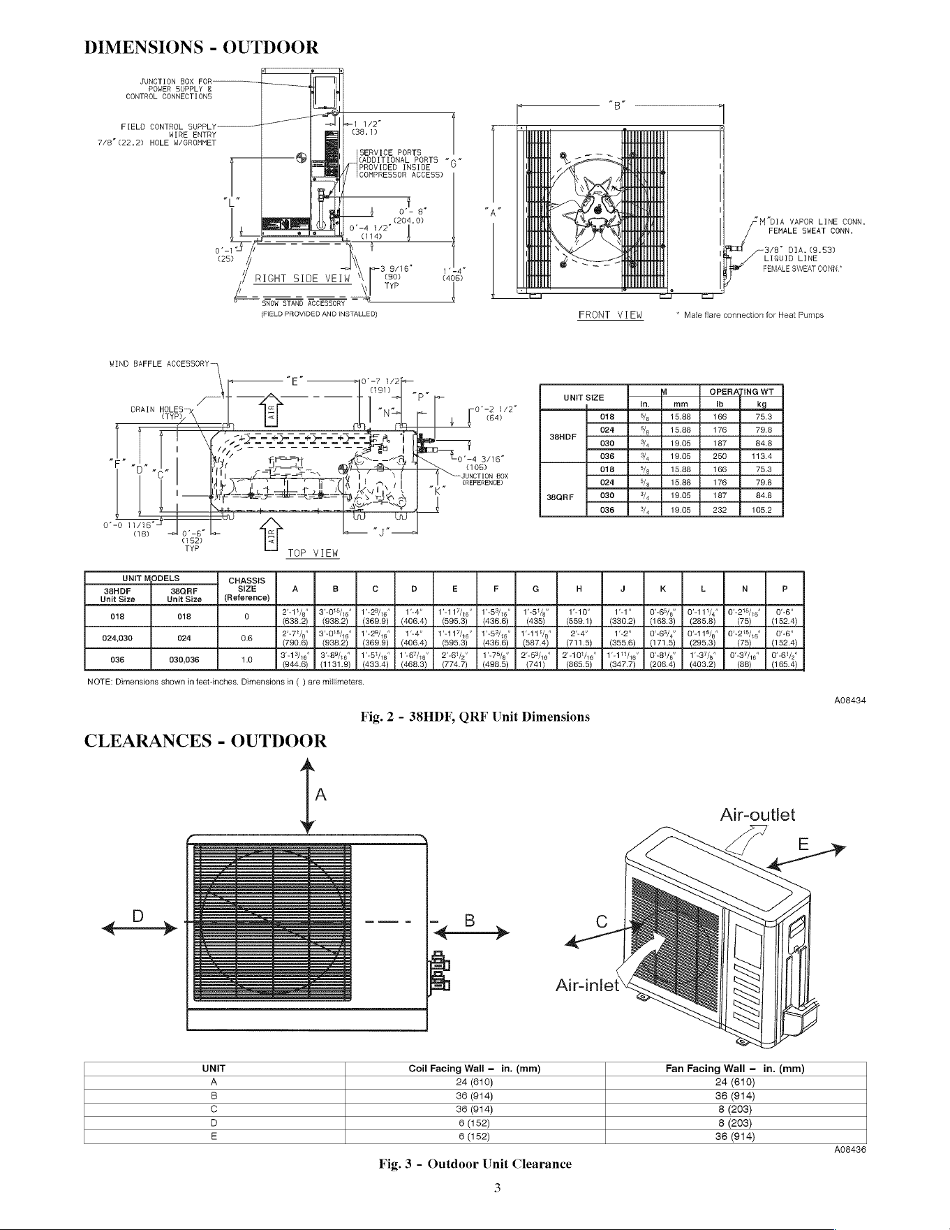
DIMENSIONS
-
OUTDOOR
JUNCTION
BOX
FOR————————
POWER
SUPPLY
&
CONTROL
CONNECTIONS
FIELD
CONTROL
SUPPLY]
.
WIRE_ENTRY
2/8"
(22.2)
HOLE
W/GROMMET
K-11
1/2"
(38.19
SERVICE
PORTS
CADDITIONAL
PORTS
*
PROVIDED
INSIDE
COMPRESSOR
ACCESS)
“M"DIA
VAPOR
LINE
CONN.
FEMALE
SWEAT
CONN.
3/8”
DIA.
(9.53)
LIQUID
LINE
FEMALE
SWEAT
CONN*
WIND
BAFFLE
ACCESSORY
DRAIN
HOLES
eTYP)
L
!
oe
gt
Torna
ape
2042
L—
aia
oad
fr
\
(25)
|
\
3
9/16"
pela
RIGHT
SIDE
VEIW
“
|
(406)
,|
TYP
pe
SNOW
STAND
ACCESSORY
~~
(FIELD
PROVIDED
AND
INSTALLED)
Je]
“-7
1/25
agi)
nae
P
|
-v
f
f
|
F
“or
aL
—
o’-0
11716"
as)
el
on
UNIT
38HDF
Unit
Size
38QRF
Unit
Size
018
o18
>
‘ ‘
se
“
5
~
o—
152)
TYP
CHASSIS
SIZE
A
Cc
Dd
(Reference)
21%,"
|
3"
"P4296"
|
1-4"
Go
ad
(108)
JUNCTION
BOX
(REFERENCE)
0'-2
1/2”
(64)
‘
re
“E
0-4
3/16
'
aN
K
E
F
VAT
ig"
|
15%
6"
411-5
1p”
FRONT
VIEW
*
Male
flare
connection
for
Heat
Pumps
UNIT
SIZE
:
M
OPERATING
WT
in.
mm
Ib
kg
oi8
5/y
15.88
166
75.3
024
Sly
15.88
176
79.8
38HDF
030
hy
19.05
187
84.8
036
Wy
19.05
250 113.4
018
Sly
15.88
166
753
024
5/g
15.88
176
79.8
38QRF
030
3/4
19.05
187
84.8
036
34
19.05
232
105.2
G
H
K
L
N
P
024,030
024
nop!
qi
a
06
2-7
3
1
406.
1-4"
406.
224g"
V1!
|
15%
ig"
|
11/5"
|
2a"
.
i
1'-10"
1
i
i
"9"
1”
|
O'-65/p”
|
O%-111/."
|
0'-275/,5”
|
0-6"
68.
52
0'-63/,"
O'-115/_"
|
O'-2°5/,6”
|
0-6"
71
52.
036
030,036
"P55"
|
1-645"
15/46"
|
3"
10
1131.
NOTE:
Dimensions
shown
in
feet-inches.
Dimensions
in
(
)
are
millimeters.
CLEARANCES
-
1'-78}p"
2'-64o"
4.
498.
2-B3/46"
|
2108/6"
41
Fig.
2
-
383HDF,
QRF
Unit
Dimensions
OUTDOOR
A
Alr-inlet
-1'/ig"
|
O'-Bt_”
|
1-37”
|
O'-37%/i5”
|
O'-6'/.”
.
65.
A08434
Ajir-outlet
UNIT
Coil
Facing
Wall
-
in.
(mm)
Fan
Facing
Wall
-—
in.
(mm)
A
24
(610)
24
(610)
B
36
(914)
36
(914)
Cc
36
(914)
8
(203)
D
6
(152)
8
(203)
E
6
(152)
36
(914)
Fig.
3
-
Outdoor
Unit
Clearance
3
A08436
Parts
List
Indoor
Unit
The
following
items
are
included
with
the
indoor
unit:
Table
1
—
Installation
Materials
Description
Qty
Usage
Baffle
(size
18)
1
Required
for
fresh
air
intake
Template
1
hoe
hangers,
piping
and
wiring
loca-
NOTE:
The
grille
and
the
User
Interface
are
not
included
with
unit.
For
User
Interface,
a
wireless
remote,
wired
remote,
or
a
Zone
Manager
can
be
ordered.
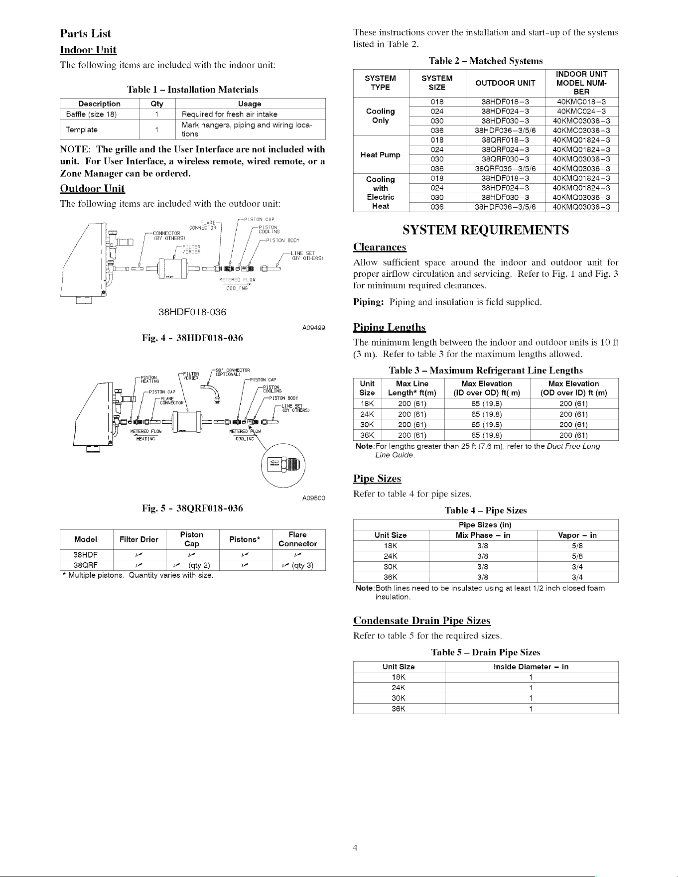
Outdoor
Unit
The
following
items
are
included
with
the
outdoor
unit:
PISTON
CAP
PISTON
COGLING
PISTON
BODY
LINE
SET
;
«BY
OTHERS)
FLARE
CONNECTOR
CONNECTOR
«BY
OTHERS)
FILTER
/DRIER
Loo
METERED
FLOW
COOLING
38HDF018-036
A09499
Fig.
4
-
38HDF018-036
90°
CONNECTOR
Fier
<OPTIGNAL?
ORE
PISTON
CAP
PISTON
COOLING
PISTON
BODY
LINE
SET
(BY
OTHERS)
coe
=|
METERED
COOLING
PISTON
CAP
FLARE,
CONNECTOR
METERED
FLOW
HEATING
These
instructions
cover
the
installation
and
start-up
of
the
systems
listed
in
Table
2.
Table
2
-
Matched
Systems
INDOOR
UNIT
eid
ila
OUTDOOR
UNIT
MODEL
NUM-
BER
018
38HDFO18—3
40KMC018—3
Cooling
024
38HDF024—3
40KMC024—3
Only
030
38HDFO30—3
40KMC03036—3
036
38HDFO36—3/5/6
|
40KMCO3036—3
018
38QRF018—3
40KMQ01824—3
024
38QRF024—3
40KMQ01824—3
Heat
Pump
030
38QRF030—3
40KMQ03036—3
036
38QRF035—3/5/6
|
40KMQ03036—3
Cooling
018
38HDFO18—3
40KMQ01824—3
with
024
38HDF024—3
40KMQ01824—3
Electric
030
38HDFO30—3
40KMQ03036—3
Heat
036
38HDFO36—3/5/6
|
40KMQ03036—3
SYSTEM
REQUIREMENTS
Clearances
Allow
sufficient
space
around
the
indoor
and
outdoor
unit
for
proper
airflow
circulation
and
servicing.
Refer
to
Fig.
1
and
Fig.
3
for
minimum
required
clearances.
Piping:
Piping
and
insulation
is
field
supplied.
Piping
Lengths
The
minimum
length
between
the
indoor
and
outdoor
units
is
10
ft
(3
m).
Refer
to
table
3
for
the
maximum
lengths
allowed.
Table
3
-
Maximum
Refrigerant
Line
Lengths
Unit
Max
Line
Max
Elevation
Max
Elevation
Size
|
Length*
ft(m)
(ID
over
OD)
ft(
m)
(OD
over
ID)
ft
(m)
18K
200
(61)
65 (19.8)
200
(61)
24K
200
(61)
65 (19.8)
200
(61)
30K
200
(61)
65 (19.8)
200
(61)
36K
200
(61)
65 (19.8)
200
(61)
Note:
For
lengths
greater
than
25
ft
(7.6
m), refer
to
the
Duct
Free
Long
Line
Guide.
Pipe
Sizes
Refer
to
table
4
for
pipe
sizes.
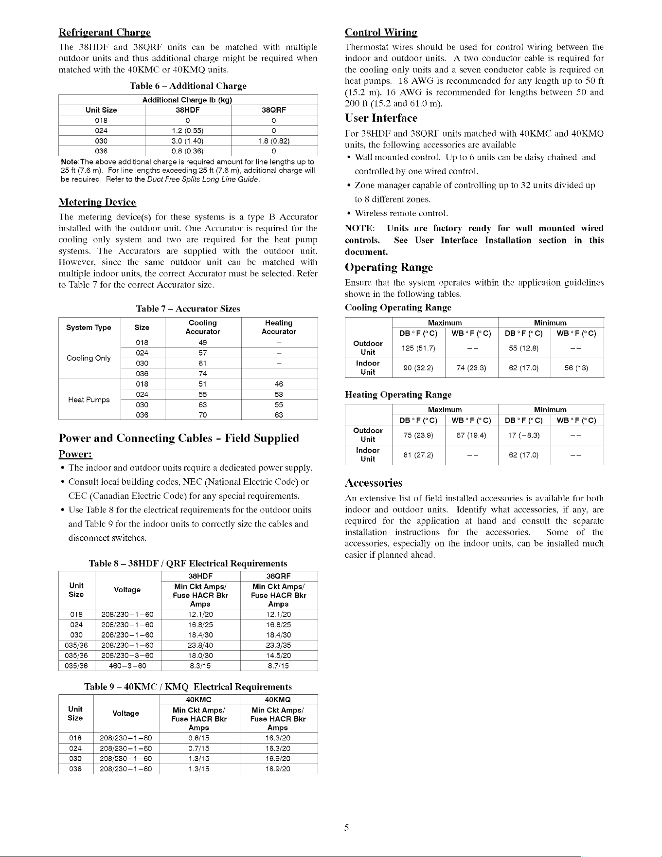
A09500
Fig.
5
-
38QRF018-036
Table
4
—
Pipe
Sizes
Pipe
Sizes
(in)
Model
Filter
Drier
Piston
Pistons*
Flare
Unit
Size
Mix
Phase
—
in
Vapor
—
in
Cap
Connector
18K
3/8
5/8
38HDF
ia
a
aa aa
24k
3/8
5/8
38QRF
w
=
(aty
2)
lal
(qty
3)
30K
3/8
3/4
*
Multiple
pistons.
Quantity
varies
with
size.
36K
3/8
3/4
Note:
Both
lines
need
to
be
insulated
using
at
least
1/2
inch
closed
foam
insulation.
Condensate
Drain
Pipe
Sizes
Refer
to
table
5
for
the
Table
5
—
Drain
Pipe
Sizes
required
sizes.
Unit
Size
Inside
Diameter
—
in
18K
24K
30K
38K
afoafoa}oa
Refrigerant
Charge
The
38HDF
and
38ORF
units
can
be
matched
with
multiple
outdoor
units
and
thus
additional
charge
might
be
required
when
matched
with
the
4OKMC
or
40KMO
units.
Table
6
—
Additional
Charge
Additional
Charge
Ib
(kg)
Unit
Size
38HDF
38QRF
018
0 0
024
1.2
(0.55)
0
030
3.0
(1.40)
1.8
(0.82)
036
0.8
(0.36)
0
Note:The
above
additional
charge
is
required
amount
for
line
lengths
up
to
25
ft
(7.6
m).
For
line
lengths
exceeding
25
ft
(7.6
m),
additional
charge
will
be
required.
Refer
to
the
Duct
Free
Splits
Long
Line
Guide.
Metering
Device
The
metering
device(s)
for
these
systems
is
a
type
B
Accurator
installed
with
the
outdoor
unit.
One
Accurator
is
required
for
the
cooling
only
system
and
two
are
required
for
the
heat
pump
systems.
The
Accurators
are
supplied
with
the
outdoor
unit.
However,
since
the
same
outdoor
unit
can
be
matched
with
multiple
indoor
units,
the
correct
Accurator
must
be
selected.
Refer
to
Table
7
for
the
correct
Accurator
size.
Table
7
—
Accurator
Sizes
Control
Wiring
Thermostat
wires
should
be
used
for
control
wiring
between
the
indoor
and
outdoor
units.
A
two
conductor
cable
is
required
for
the
cooling
only
units
and
a
seven
conductor
cable
is
required
on
heat
pumps.
18
AWG
is
recommended
for
any
length
up
to
50
ft
(15.2
m).
16
AWG
is
recommended
for
lengths
between
50
and
200
ft
(15.2
and
61.0
m).
User
Interface
For
38HDF
and
38QRF
units
matched
with
40KMC
and
40KMQ
units,
the
following
accessories
are
available
¢
Wall
mounted
control.
Up
to
6
units
can
be
daisy
chained
and
controlled
by
one
wired
control.
¢
Zone
manager
capable
of
controlling
up
to
32
units
divided
up
to
8
different
zones.
¢
Wireless
remote
control.
NOTE:
Units
are
factory
ready
for
wall
mounted
wired
controls.
See
User
Interface
Installation
section
in
this
document.
Operating
Range
Ensure
that
the
system
operates
within
the
application
guidelines
shown
in
the
following
tables.
Cooling
Operating
Range
System
T
si
Cooling
Heating
Maximum
Minimum
ystem
Type
126
Accurator Accurator
DB°F
CC)
|
WB°F(CC)
|
DB°FCC)
|
WB°F(CC)
018
49
=
Outdoor
cooling
Only
024
57
=
Unit
125
(51.7)
--
55 (12.8)
--
030
61
-
Indoor
.
90
(32.2
74
(23.3
62
(17.0
56
(13
036
74
=
Unit
(32.2) (23.3) (17.0)
(13)
018
51
46
Heat
Pumps
024
55
53
Heating
Operating
Range
030
63
55
7
+
036
70
a3
Maximum
Minimum
DB°FCC)
|
WB°F(°C)
|
DB°F(°C)
|
WB°F(°C)
‘ ‘ ‘
Outdoor
|
75
(28.9
87
(19.4
17
(-8.3
--
Power
and
Connecting
Cables
-
Field
Supplied
Unit
(28.8) (18.4)
(~8.3)
Power:
indoor
81
(27.2)
—-
62 (17.0)
—-
¢
The
indoor
and
outdoor
units
require
a
dedicated
power
supply.
¢
Consult
local
building
codes,
NEC
(National
Electric
Code)
or
Accessories
CEC
(Canadian
Electric
Code)
for
any
special
requirements.
¢
Use
Table
8
for
the
electrical
requirements
for
the
outdoor
units
and
Table
9
for
the
indoor
units
to
correctly
size
the
cables
and
disconnect
switches.
Table
8
-
38HDF
/
QRF
Electrical
Requirements
38HDF
38QRF
Unit
Voltage
Min
Ckt
Amps/
Min
Ckt
Amps/
Size
Fuse
HACR
Bkr
Fuse
HACR
Bkr
Amps Amps
018
208/230
—1-60
12.1/20
12.1/20
024
208/230—1-60
16.8/25
16.8/25
030
208/230
—1-60
18.4/30
18.4/30
035/36
208/230—1-60
23.8/40
23.3/35
035/36
208/230-3-60
18.0/30
14.5/20
035/36
460—-3-—60
8.3/15
87/15
Table
9
-
40KMC
/
KMQ
Electrical
Requirements
40KMC
40KMQ
Unit
Voltage
Min
Ckt
Amps/
Min
Ckt
Amps/
Size
Fuse
HACR
Bkr
Fuse
HACR
Bkr
Amps Amps
018
208/230
—1-60
0.83/15
16.3/20
024
208/230—1-60
O.7/15
16.3/20
030
208/230
—1-60
1.3/15
16.9/20
036
208/230
—1-60
1.3/15
16.9/20
An
extensive
list
of
field
installed
accessories
is
available
for
both
indoor
and
outdoor
units.
Identify
what
accessories,
if
any,
are
required
for
the
application
at
hand
and
consult
the
separate
installation
instructions
for
the
accessories.
Some
of
the
accessories,
especially
on
the
indoor
units,
can
be
installed
much
easier
if
planned
ahead.
INSTALLATION
Complete
Pre-installation
Checks
1.
Unpack
Unit
-
Store
the
indoor
and
outdoor
units
in
the
original
packaging
until
it
is
moved
to
the
final
site
for
in-
stallation.
When
unpacking
indoor
unit,
be
careful
not
to
lift
unit
by
condensate
drain
discharge
pipe
or
by
refrigerant
connections.
bo
.
Inspect
Shipment
-
Upon
receipt
of
shipment,
check
the
indoor
and
outdoor
units
for
damage.
If
there
is
any
dam-
age,
forward
claim
papers
directly
to
the
transportation
company.
Manufacturer
is
not
responsible
for
damage
in-
curred
in
transit.
3.
Inspect
Parts
Supplied
With
Units
—
Check
all
items
against
parts
list
(see
page
4).
If
any
items
are
missing,
noti-
fy
your
distributor
or
Carrier
office.
To
prevent
loss
or
damage,
leave
all
parts
in
original
packages
until
installation.
Consider
System
Requirements
1.
Consult
local
building
codes
and
NEC
for
special
instaila-
tion
requirements.
bo
.
When
deciding
the
location
of
the
indoor
and
outdoor
units,
ensure
that
the
piping
run
does
not
exceed
the
allowed
dis-
tances
listed
in
Table
3.
3.
Make
sure
the
indoor
and
outdoor
units
are
easily
accessible
to
electrical
power.
4.
Allow
sufficient
clearances
for
airflow,
wiring,
refrigerant
piping, and
servicing
the
unit.
See
Fig.
2
and
Fig.
3.
5.
Condensate
piping
can
be
directed
through
the
inside
wail
to
an
approved
drain
or
straight
outside.
INSTALL
INDOOR
UNIT
Plan
the
installation
carefully
before
you
begin.
1.
Select
indoor
unit
location.
a.
A
location
that
can
bear
the
weight
of
the
unit.
b.
Install
the
unit
a
centrally
as
possible
in
the
room.
c.
Choose
a
location
that
does
not
obstruct
air
circulation.
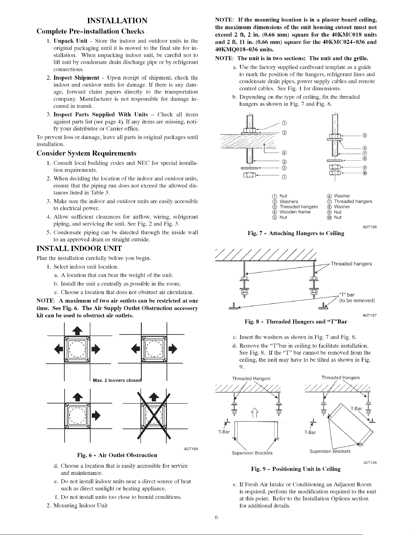
NOTE:
A
maximum
of
two
air
outlets
can
be
restricted
at
one
time.
See
Fig.
6.
The
Air
Supply
Outlet
Obstruction
accessory
kit
can
be
used
to
obstruct
air
outlets.
t
‘
’ ‘
it
¥ i q
\
, ‘ i
s ¢ “ ¢
Max.
2
louvers
closed
‘ ‘
it
1
‘
i
x ’
4
A07184
Fig.
6
-
Air
Outlet
Obstruction
d.
Choose
a
location
that
is
easily
accessible
for
service
and
maintenance.
e.
Do
not
install
indoor
units
near
a
direct
source
of
heat
such
as
direct
sunlight
or
heating
appliance.
f.
Do
not
install
units
too
close
to
humid
conditions.
2.
Mounting
Indoor
Unit
NOTE:
If
the
mounting
location
is
in
a
plaster
board
ceiling,
the
maximum
dimensions
of
the
unit
housing
cutout
must
not
exceed
2
ft,
2
in.
(0.66
mm)
square
for
the
40KMC018
units
and
2
ft.
11
in.
(0.66
mm)
square
for
the
40KMC024-036
and
40KMQ018-036
units.
NOTE:
The
unit
is
in
two
sections:
The
unit
and
the
grille.
a.
Use
the
factory
supplied
cardboard
template
as
a
guide
to
mark
the
position
of
the
hangers,
refrigerant
lines
and
condensate
drain
pipes,
power
supply
cables
and
remote
control
cables.
See
Fig.
1
for
dimensions.
b.
Depending
on
the
type
of
ceiling,
fix
the
threaded
hangers
as
shown
in
Fig.
7
and
Fig.
8.
4
|
C
—©®
J
@
=—__
@
©D-———
©
1D
®
@
Nut
©
Washer
@
Washers
@
Threaded
hangers
@®
Threaded
hangers
Washer
@
Wooden
frame
@®
Nut
®
Nut
Nut
A07186
Fig.
7
-
Attaching
Hangers
to
Ceiling
é
|—_}*
Threaded
hangers
L
a
“T
bar
La”
be
removed)
ale
AO7187
1
“4
Fig.
8
-
Threaded
Hangers
and
“T” Bar
c.
Insert
the
washers
as
shown
in
Fig.
7
and
Fig.
8.
d.
Remove
the
“T”bar
in
ceiling
to
facilitate
installation.
See
Fig.
8.
If
the
“T”
bar
cannot
be
removed
from
the
ceiling,
the
unit
may
have
to
be
tilted
as
shown
in
Fig.
9,
Threaded
Hangers
Threaded
Hangers
x,
LLe
|
te”
&
S|
|
x
ef
pe
T-Bar
T-Bar
Supension
Brackets
Supension
Brackets
A07I88
Fig.
9
-
Positioning
Unit
in
Ceiling
e.
If
Fresh
Air
Intake
or
Conditioning
an
Adjacent
Room
is
required,
perform
the
modification
required
to
the
unit
at
this
point.
Refer
to
the
Installation
Options
section
for
additional
details.
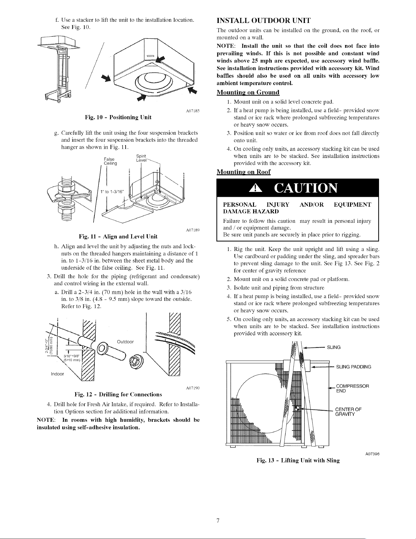
f.
Use
a
stacker
to
lift
the
unit
to
the
installation
location.
See
Fig.
10.
A07L85
Fig.
10
-
Positioning
Unit
g.
Carefully
lift
the
unit
using
the
four
suspension
brackets
and
insert
the
four
suspension
brackets
into
the
threaded
hanger
as
shown
in
Fig.
11.
Spirit
False
Ceiling
Level
A07189
Fig.
11
-
Align
and
Level
Unit
h.
Align
and
level
the
unit
by
adjusting
the
nuts
and
lock-
nuts on
the
threaded
hangers
maintaining
a
distance
of
1
in.
to
1-3/16
in.
between
the
sheet
metal
body
and
the
underside
of
the
false
ceiling.
See
Fig.
11.
3.
Drill
the
hole
for
the
piping
(refrigerant
and
condensate)
and
control
wiring
in
the
external
wail.
a.
Drill
a
2-3/4
in.
(70
mm)
hole
in
the
wall
with
a
3/16
in.
to
3/8
in.
(4.8
-
9.5
mm)
slope
toward
the
outside.
Refer
to
Fig.
12.
(70/80
ram)
~
Outdoor
”
3e"s3/e"
Om
~
\erto
mm)
Y
©)
Indoor
A07L90
Fig.
12
-
Drilling
for
Connections
4.
Drill
hole
for
Fresh
Air Intake,
if
required.
Refer
to
Instaila-
tion
Options
section
for
additional
information.
NOTE:
In
rooms
with
high
humidity,
brackets
should
be
insulated
using
self-adhesive
insulation.
INSTALL
OUTDOOR
UNIT
The
outdoor
units
can
be
installed
on
the
ground,
on
the
roof,
or
mounted
on
a
wall.
NOTE:
Install
the
unit
so
that
the
coil
does
not
face
into
prevailing
winds.
If
this
is
not
possible
and
constant
wind
winds
above
25
mph
are
expected,
use
accessory
wind
baffle.
See
installation
instructions
provided
with
accessory
kit.
Wind
baffles
should
also
be
used
on
all
units
with
accessory
low
ambient
temperature
control.
Mounting
on
Ground
1.
Mount
unit
on
a
solid
level
concrete
pad.
2.
Ifa
heat
pump
is
being
installed,
use
a
field-
provided
snow
stand
or ice
rack
where
prolonged
subfreezing
temperatures
or
heavy
snow
occurs.
3.
Position
unit
so
water
or ice
from
roof
does
not
fall
directly
onto
unit.
4.
On
cooling
only
units,
an
accessory
stacking
kit
can
be
used
when
units
are
to
be
stacked.
See
installation
instructions
provided
with
the
accessory
kit.
Mounting
on
Roof
&
CAUTION
PERSONAL
—=
INJURY
DAMAGE
HAZARD
Failure
to
follow
this
caution
may
result
in
personal
injury
and
/
or
equipment
damage.
Be
sure
unit
panels
are
securely
in
place
prior
to
rigging.
AND/OR
EQUIPMENT
1.
Rig
the
unit.
Keep
the
unit
upright
and
lift
using
a
sling.
Use
cardboard
or
padding
under
the
sling,
and
spreader
bars
to
prevent
sling
damage
to
the
unit.
See
Fig
13.
See
Fig.
2
for
center
of
gravity
reference
.
Mount
unit
on
a
solid
concrete
pad
or
platform.
Ww
be
.
Isolate
unit
and
piping
from
structure
fs
.
Ifa
heat
pump
is
being
installed,
use
a
field-
provided
snow
stand
or ice
rack
where
prolonged
subfreezing
temperatures
or
heavy
snow
occurs.
5.
On
cooling
only
units,
an
accessory
stacking
kit
can
be
used
when
units
are
to
be
stacked.
See
installation
instructions
provided
with
accessory
kit.
|
SLING
PADDING
|.
COMPRESSOR
[END
HA
|.
CENTER
OF
UATE
GRAVITY
OE
LeU
i
Fig.
13
-
Lifting
Unit
with
Sling
A07396
Mounting
Unit
on
Wall
The
units
can
also
be
mounted
on
the
wall
using
the
accessory
mounting
kit.
Complete
Outdoor
Refrigerant
Piping
Connec-
tions
Follow
the
following
general
guidelines:
1.
Use
refrigerant
grade
field
—
supplied
tubing.
Refer
to
Table
4
for
the
correct
line
sizes.
2.
Do
not
use
less
than
10
ft
(93.05
m)
of
interconnecting
tubing.
UNIT
DAMAGE
HAZARD
Failure
to
follow
this
caution
may
result
in
equipment
damage
or
improper
operation.
If
any
section
of
pipe
is
buried,
there
must
be
a
6
in.
(152.4
mm)
vertical
rise
to
the
valve
connections
on
the
outdoor
unit.
If
more
than
the
recommended
length
is
buried,
refrigerant
may
migrate
to
cooler,
buried
section
during
extended
periods
of
system
shutdown.
This
causes
refrigerant
slugging
and
could
possibly
damage
the
compressor
at
start-up.
When
more
than
80
ft
(24.4
m)
of
interconnecting
tubing
is
used,
consult
the
Duct-Free
Split
System
Long
Line
Application
Guide
for
required
accessories.
3.
Insulate
both
lines.
A
minimum
of
1/2
inch
foam
pipe
insu-
lation
is
recommended.
4.
Run
the
refrigerant tubes
as
directly
as
possible
and
avoid
unnecessary
turns
and
bends.
5.
Suspend
refrigerant tubes
to
avoid
damage
to
insulation
or
tubes
so
they
do
not
transmit
vibration
to
the
structure.
6.
When
passing
refrigerant tubes
through
the
wall,
seal
the
opening
so
rain
and
insects
do
not
enter
the
structure.
Leave
some
slack
in
refrigerant tubes
between
structure
and
out-
door
unit
to
absorb
vibration.
NOTE:
A
fusible
plug
is
located
in
unit
suction
line;
do
not
cap
this
plug.
If
local
codes require
additional
safety
devices,
install
as
directed.
Connection
at
Outdoor
Unit
UNIT
DAMAGE
HAZARD
Failure
to
follow
this
caution
may
result
in
equipment
damage
or
improper
operation.
To
prevent
damage
to
unit
or
service
valves
observe
the
following:
¢
A
brazing
shield
MUST
be
used.
¢
Wrap
service
valves
with wet
cloth
or
use
a
heat
sink
material.
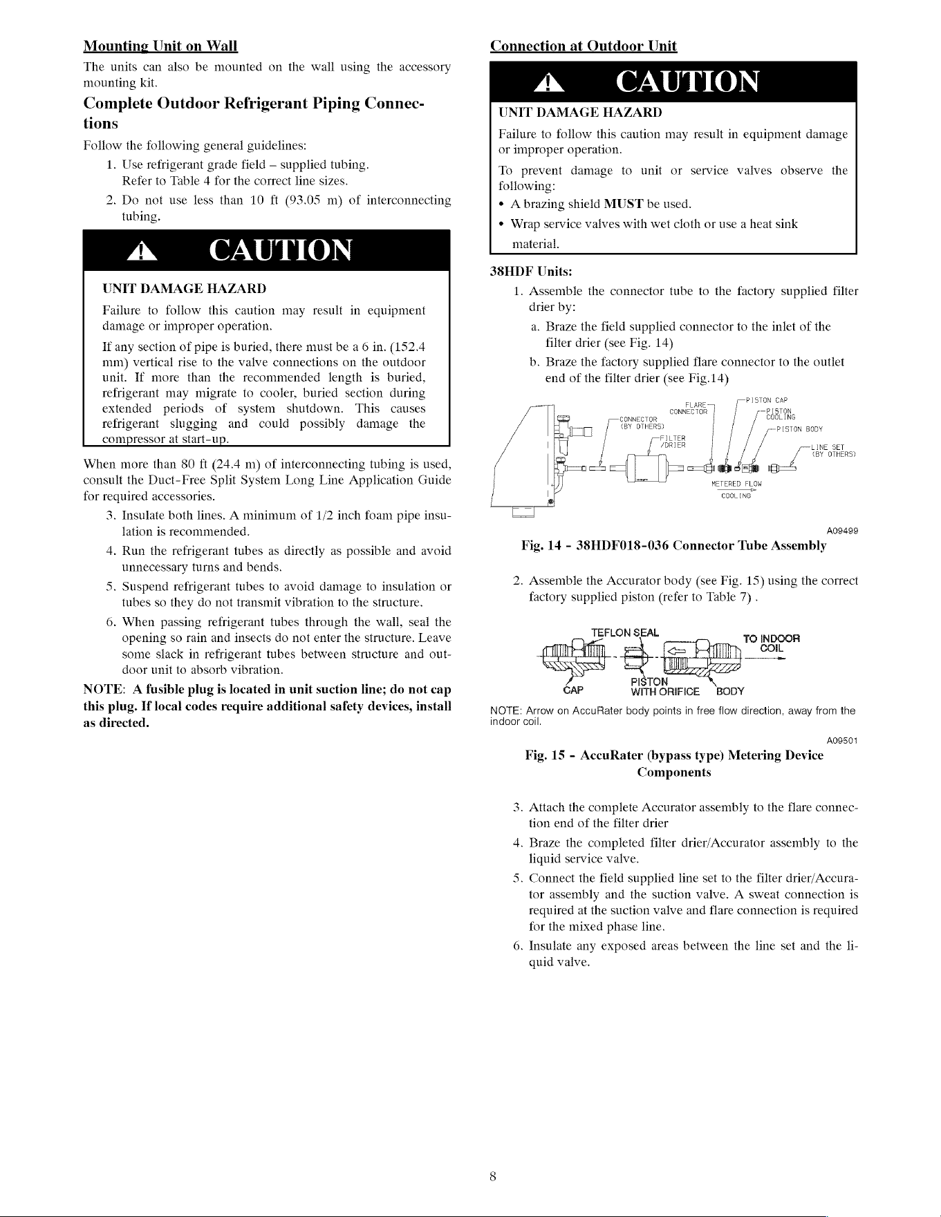
38HDF
Units:
1.
Assemble
the
connector
tube
to
the
factory
supplied
filter
drier
by:
a.
Braze
the
field
supplied
connector
to
the
inlet
of
the
filter
drier
(see Fig.
14)
b.
Braze
the
factory
supplied
flare
connector
to
the
outlet
end
of
the
filter
drier
(see
Fig.14)
ate)
oe,
CONNECTOR
CONNECTOR
COCLING
<BY
OTHERS)
PISTON
BODY
FILTER
7DRIER
LINE.
SET
<BY
OTHERS?
é
i;
=f
METERED
FLOW
ETERED
Fe
COGLING
Aogagg
Fig.
14
-
38HDF018-036
Connector
Tube
Assembly
2.
Assemble
the
Accurator
body
(see Fig.
15)
using
the
correct
factory
supplied
piston
(refer
to
Table
7)
.
TEFLON
SEAL
TO
INDOOR
COIL
2
a
eae
PISTON
WITH
ORIFICE
BODY
NOTE:
Arrow
on
AccuRater
body
points
in
free
flow
direction,
away
from
the
indoor
coil.
AO9501
Fig.
15
-
AccuRater
(bypass
type)
Metering
Device
Components
3.
Attach
the
complete
Accurator
assembly
to
the
flare
connec-
tion
end
of
the
filter
drier
4.
Braze
the
completed
filter
drier/Accurator
assembly
to
the
liquid
service
valve.
5.
Connect
the
field
supplied
line
set
to
the
filter
drier/Accura-
tor
assembly
and
the
suction
valve.
A sweat
connection
is
required
at
the
suction
valve
and
flare
connection
is
required
for
the
mixed
phase
line.
6.
Insulate
any
exposed
areas
between
the
line
set
and
the
li-
quid
valve.
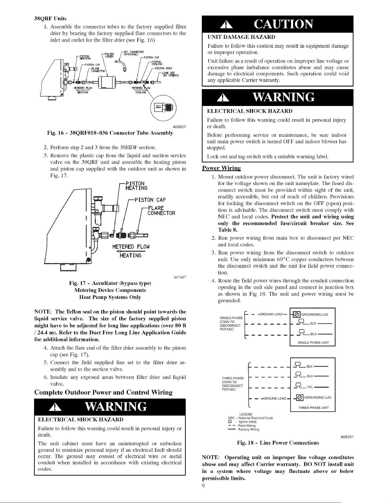
38QRF
Units
1.
Assemble
the
connector
tubes
to
the
factory
supplied
filter
drier
by
brazing
the
factory
supplied
flare
connectors
to
the
inlet
and
outlet
for
the
filter
drier
(see Fig.
16)
90°
CONNECTOR
ist
FILTER
COPTIONAL)
HEXTING
(DRIER
PISTON
CAP
PISTON
PISTON
CAP
ERaLINe
FLARE
PISTON
BODY
CONNECTOR
LINE
SET
(BY
OTHERS)
METERED
FLOW
ese
METERED
PLOW
ne
HEATING COOLING
AOQ507
Fig.
16
-
38QRF018-036
Connector
Tube
Assembly
.
Perform
step
2
and
3
from
the
38HDF
section.
Ww
.
Remove
the
plastic
cap
from
the
liquid
and
suction
service
valve
on
the
38ORF
unit
and
assemble
the
heating
piston
and
piston
cap
supplied
with
the
outdoor
unit
as
shown
in
Fig.
17.
ISTON
CAP
FLARE
CONNECTOR
METERED
FLOW
@oooonnooonn
HEATING
A07407
Fig.
17
-
AccuRater
(bypass
type)
Metering
Device
Components
Heat
Pump
Systems
Only
NOTE:
The
Teflon
seal
on
the
piston
should
point
towards
the
liquid
service
valve.
The
size of
the
factory
supplied
piston
might
have
to
be
adjusted
for
long
line
applications
(over
80
ft
/
24.4
m).
Refer
to
the
Duct
Free
Long
Line
Application
Guide
for
additional
information.
4.
Attach
the
flare
end
of
the
filter
drier
assembly
to
the
piston
cap
(see Fig.
17).
5.
Connect
the
field
supplied
line
set
to
the
filter
drier
as-
sembly
and
to
the
suction
valve.
6.
Insulate
any
exposed
areas
between
filter
drier
and
liquid
valve.
Complete
Outdoor
Power
and
Control
Wiring
ELECTRICAL
SHOCK
HAZARD
Failure
to
follow
this
warning
could
result
in
personal
injury
or
death.
The
unit
cabinet
must
have
an
uninterrupted
or
unbroken
ground
to
minimize
personal
injury
if
an
electrical
fault
should
occur,
The
ground
may
consist
of
electrical
wire
or
metal
conduit
when
installed
in
accordance
with
existing
electrical
codes.
&
CAUTION
UNIT
DAMAGE
HAZARD
Failure
to
follow
this
caution
may
result
in
equipment
damage
or
improper
operation.
Unit
failure
as
a
result
of
operation
on
improper
line
voltage
or
excessive
phase
imbalance
constitutes
abuse
and
may
cause
damage
to
electrical
components.
Such
operation
could
void
any
applicable
Carrier
warranty.
&
WARNING
ELECTRICAL
SHOCK
HAZARD
Failure
to
follow
this
warning
could
result
in
personal
injury
or
death.
Before
performing
service
or
maintenance,
be
sure
indoor
unit
main
power
switch
is
turned
OFF
and
indoor
blower
has
stopped.
Lock
out
and
tag
switch
with
a
suitable
warning
label.
Power
Wiring
1.
Mount
outdoor
power
disconnect.
The
unit
is
factory
wired
for
the
voltage
shown
on
the
unit
nameplate.
The
fused
dis-
connect
switch
must
be
provided
within
sight
of
the
unit,
readily
accessible,
but
out
of
reach
of
children.
Provisions
for
locking
the
disconnect
switch
on
the
OFF
(open)
posi-
tion
is
advisable.
The
disconnect
switch
must
comply
with
NEC
and
local
codes.
Protect
the
unit
and
wiring
using
only
the
recommended
fuse/circuit
breaker
size.
See
Table
8.
2.
Run
power
wiring
from
main
box
to
disconnect
per
NEC
and
local
codes.
an
.
Run
power
wiring
from
the
disconnect
switch
to
outdoor
unit.
Use
only
minimum
60°C
copper
conductors
between
the
disconnect
switch
and
the
unit
for
field
power
connec-
tion.
4.
Route
the
field
power
wires
through
the
conduit
connection
opening
in
the
unit
side
panel
and
connect
in
junction
box
as
shown
in
Fig
18.
The
unit
and
power
wiring
must
be
grounded.
==
=GROUND
LEAD
=
-{@]
crounowe
LUG
SINGLE-PHASE
CONNTO)
=f
.
ax
DISCONNECT
PER
NEC
om
JZ
tak
SINGLE-PHASE
UNIT
THREE-PHASE
CONN
TO
DISCONNECT
[oo
A
VEL
PER
NEC
maz
=GROUND
LEAD
uma
GROUNDING
LUG
THREE-PHASE
UNIT
LEGEND
NEC
--
National
Electrical
Code
fA
--
Splice
(field)
==
'
Field
Wiring
tmmmes
Factory
Wiring
A08251
Fig.
18
-
Line
Power
Connections
NOTE:
Operating
unit
on
improper
line
voltage
constitutes
abuse
and
may
affect
Carrier
warranty.
DO
NOT
install
unit
in
a
system
where
voltage
may
fluctuate
above
or
below
permissible
limits.
9
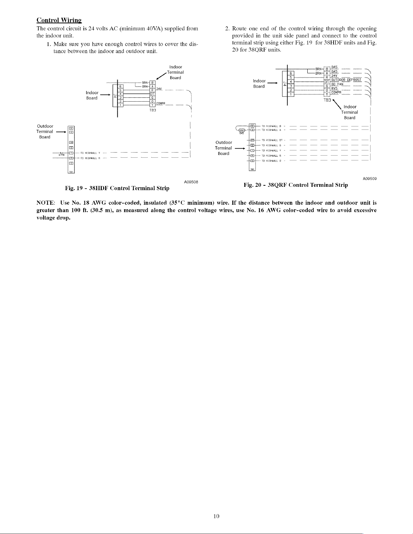
Control
Wiring
The
control
circuit
is
24
volts
AC
(minimum
40VA)
supplied
from
the
indoor
unit.
1.
Make
sure
you
have
enough
control
wires
to
cover
the
dis-
tance
between
the
indoor
and
outdoor
unit.
Indoor
Terminal
Board
Indoor
~
Board
i
ae
ae
\
Outdoor
|
Terminal
——>
Board
|
a
Lee
TES
AE
ISHIRAL
Ewen
mm
mr
rr
rr rn
|
foo
7)
HEGHMALL
Fe
©
TT
A09508
Fig.
19
-
38HDF
Control
Terminal
Strip
2.
Route
one end
of
the
control
wiring
through
the
opening
rovided
in
the
unit
side
panel
and
connect
to
the
control
Pp
Pp
terminal
strip
using
either
Fig.
19
for
33HDF
units
and
Fig.
20
for
38ORF
units.
Indoor
Board
\
Indoor
Terminal
Board
|
EH
—
v0
siseeiai
@
- ~
—
—
—
— —
—
—
=|
ae
wos
TO
HEGHGRLL
&
—_
vow
TO
HLSOGRLA,
OF
_T
TTT
TT TT
Outdoor
1G
MIG,
& =
——
—
$s
——
S$
——
S$
——
ss
Terminal
—+>
09
teil
¢
=<
——
——
—— ——
— —
—
—|
Board
[EB]
80
AEGHWALL
Ro
|
[Bplen
#0
wisewL
@
©)
——
——-
—-
——-
——
——
——
—
A09509
Fig.
20
-
38QRF
Control
Terminal
Strip
NOTE:
Use
No.
18
AWG
color-coded,
insulated
35°C
minimum)
wire.
If
the
distance
between
the
indoor
and
outdoor
unit
is
greater than
100
ft.
30.5
m),
as
measured
along
the
control
voltage
wires,
use
No.
16
AWG
color-coded
wire
to
avoid
excessive
voltage
drop.
10
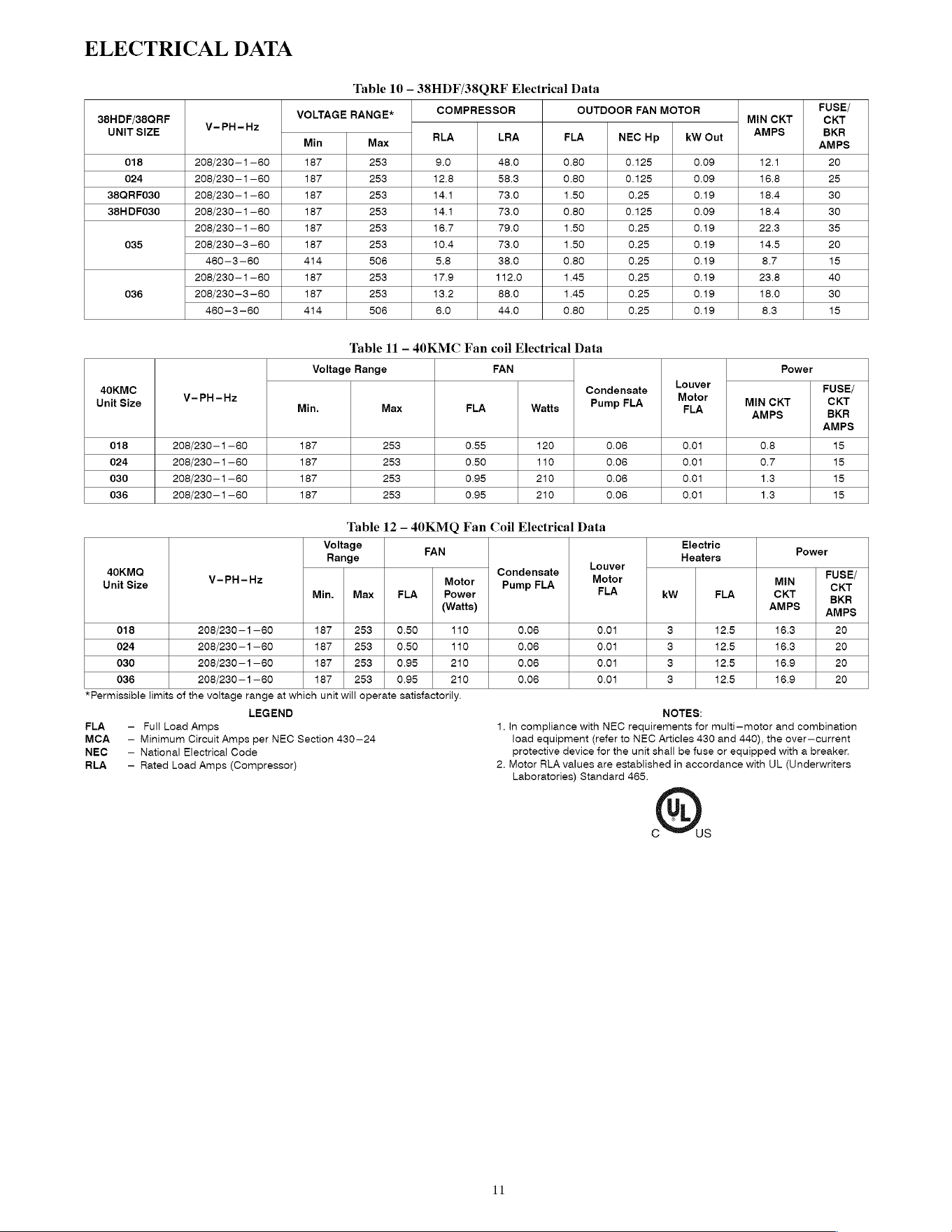
ELECTRICAL
DATA
Table
10
—38HDF/38QRF
Electrical
Data
COMPRESSOR
OUTDOOR
FAN
MOTOR
FUSE/
38HDF/38QRF
V-PH-Hz
VOLTAGE
RANGE*
MIN
CKT CKT
UNIT
SIZE
ven
AMPS
BKR
Min
Max
RLA LRA
FLA
NEC
Hp
kW
Out
AMPS
018
208/230
—1-60
187
253
9.0
48.0 0.80
0.125
0.09
12.4
20
024
208/230
—1-60
187
253
12.8
58.3
0.80
0.125
0.09
16.8
25
38QRF030
208/230
—1-60
187
253
14.4
73.0
1.50
0.25 0.19
18.4
30
38HDFO30
208/230
—1-60
187
253
14.4
73.0 0.80
0.125
0.09
18.4
30
208/230
—1-60
187
253
16.7
79.0
1.50
0.25 0.19
22.3
35
035
208/230-3-60
187
253
10.4
73.0
1.50
0.25 0.19
14.5
20
460—-3-—60
414 506
5.8
38.0 0.80 0.25 0.19
8.7
15
208/230
—1-60
187
253
17.9
112.0
1.45
0.25 0.19 23.8
40
036
208/230-3-60
187
253
13.2
88.0
1.45
0.25 0.19
18.0
30
460—-3-—60
414 506
6.0
44.0 0.80 0.25 0.19
8.3
15
Table
11
—
40K
MC
Fan
coil
Electrical
Data
Voltage
Range
FAN
Power
Louver
40KMC
Condensate
FUSE/
ee
V-PH-Hz
Motor
Unit
Size
:
Pump
FLA MIN
CKT CKT
Min.
Max
FLA
Watts
FLA
AMPS
BKR
AMPS
018
208/230—1—60
187
253
0.55
120
0.08
0.01
0.8
15
024
208/230
—1-60
187
253
0.50
110
0.06
0.01
0.7
15
030
208/230
—1-60
187
253
0.95
210
0.06
0.01
1.3
15
036
208/230
—1-60
187
253
0.95
210
0.06
0.01
1.3
15
Table
12
—-
40KMQ
Fan
Coil
Electrical
Data
Voltage
FAN
Electric
Power
Range
L
Heaters
ouver
40KMQ
Condensate
FUSE/
Unit
Size
V-PH-Hz
Motor
|
Pump
FLA
Motor
MIN
CKT
Min.
|
Max
|
FLA
|
Power
FLA
kw
FLA
CKT
BKR
(Watts)
AMPS
|
anaps
018
208/230
—1-60
187
253
0.50
110
0.06
0.01
3
12.5
16.3 20
024
208/230
—1-60
187
253
0.50
110
0.06
0.01
3
12.5
16.3 20
030
208/230
—1-60
187
253
0.95
210
0.06
0.01
3
12.5 16.9
20
036
208/230
—1-60
187
253
0.95
210
0.06
0.01
3
12.5 16.9
20
*Permissible
limits
of
the
voltage
range
at
which
unit
will
operate
satisfactorily.
LEGEND
NOTES:
FLA
-
MCA
-
NEC
-
RLA
-
Full
Load
Amps
Minimum
Circuit
Amps
per
NEC
Section
430-24
National
Electrical
Code
Rated
Load
Amps
(Compressor)
1.
In
compliance
with
NEC
requirements
for
multi-motor
and
combination
load
equipment
(refer
to
NEC
Articles
430
and
440),
the
over—current
protective
device
for
the
unit
shall
be
fuse
or
equipped
with
a
breaker.
2.
Motor
RLA
values
are
established
in
accordance
with
UL
(Underwriters
Laboratories)
Standard
465.
11
Cc
@
US
DISPLAY
PCB
@
2PCB
1
sfa[s]e|a
2
SLON
Odo
TM-COIL
TM-AIR
&
MODULAR
“D”
~
CONTROL
1PCB
S
SLoN
GRA/YEL-[F15+
GRN/YEL-
oe
TO
UNIT
DISCONNECT
(USE
CABLE
PROVIDED)
EQUIP.
GND
40KMC
GLOBAL
CASSETTE
~
38HDF OUTDOOR
CONDENSER
Ws
1
2
aLk
Wy
8s
—
Spo
NOTE
8
cout
ovo
Spe
me
208/230
CHS
1PH
YEL
i.
BLK
a
of
am
\(SEE
NOTE
103
°
ouTsoon
NIT
BLK
t
K
RR
dal
gm
|
DISCONNECT
YEL
BLU
ct
COMP
BLK BLK
aly
—____}
co
——_Cenecloniclo
we
YEL
ORN/YEL,
au
K
alk
OFM
“TQ
CASSETTE
Y
—
——
——
——
LLPS
ieRN
oOo
0
OFS
ea
apes
RED
TO
CASSETTE
R
—
——-~
——
——
1.
IF
ANY
OF
THE
ORIGINAL
RE
FURH] SHED
Cc
CONT
ACTOR
(PCB
MAIN
CONTROL PRINTED CIRCUIT
BOARD
dust
BE
ooo
ri
1T
MUST
2POB
DISPLAY
BOARD
WITH
TYPE
$O°C WIRE
OR
115
UVNLENT,
3PCB
PRINTED CIRCUIT
BOARD
FOR
ELECTRIC
HEAT
2.
WIRE
IN
Acconpance
WITH
NATIONAL
a
ae
8
caeneeney
VALVE
SOLENOID
ELECTRICAL
CODE
(N.E.C.9
AND
LOCAL
CODES.
CRANCASE
HEATER SWITCH
3
bes
esr
etme
Sy
SE
esa
ee
ee
ee
ccm
DRAIN
PUMP
7B
TERMINAL
BL
+
ne
E-HTR
ELECTRIC
HEATER
™
THERMAL
OVERLO:
FAN
CAPACITOR
TRAN
TRANSFORMER
$.
INDOOR
UNIT
Taro
HAS
INTERNAL
24
THERMAL
FUSE
ON
EQUIP.GND.
EQUIPMENT
GROUND
THE
PRIMARY
51D!
FS
FLOAT
SWITCH
INFRARED
CONNECTION
70,8
INSERTED
ON
YS"
(REPLACE
@ND
GROUND
(2)
TERMINAL
(MARKED)
TNE
AG
tad
etetoay
HASTALLED
“Che!
GoWNEgTON
FoR
{CR
OPTION,
ves
TNDDOR
ea
RTO
TERMINAL
(UNHARKED)
TERMINAL,
STREP
FOR
CARREER
ROOM
CONTROLLER
(CRC?
CONNECT
2ON.
SALACE
COMPRESSOR
CRANCKCASE
HEATER
INSTALLED
ON
S38QRFO3S,
AND
38QRFO30.
3
VIP
INDOOR
TEST
POINT
@
LLPS
L1GUID
LOW
PRESSURE
SHITEH
ED
terninas,
a.ook
-
OUTDOOR
UNIT,
TRANSFORMER,
38
FACTORY
WIRED
FOR
230".
FOR
20eV
HOVE
LM
-LOUVER
MOTOR
2
ean
FACTORY
WIREN(
A
Rt
Ht
UNS
LOWER
MICRO
SHITCH
ACTORY
WIRING
THE
BLACK
WIRE
TO
THE
208V
T.
ts)
Cime?
switch
———
FIELD
CONTROL
WIRING
30.
USE
MINIMUM
GO"C
WERE
FOR THE
FIELD POWER
WIRING.
GAS
—OUTNOOR
AIR
SENSOR
OFN
©
OU3DO0R
FAN
NOTOR
OFR
©
QUTDOOR
FAN
RELAY
OL
OVERLOAD
FIELD POWER
WIRING
ACCESSORY
OR
OPTIONAL
WIRING
PLUG
CONNECTOR
TEMPERATURE
RESISTANCE
°F °C
Q
5
35
6,500
72 22
11,400
32
9
32,500
ALL
THERMISTORS
ARE
IDENTICAL
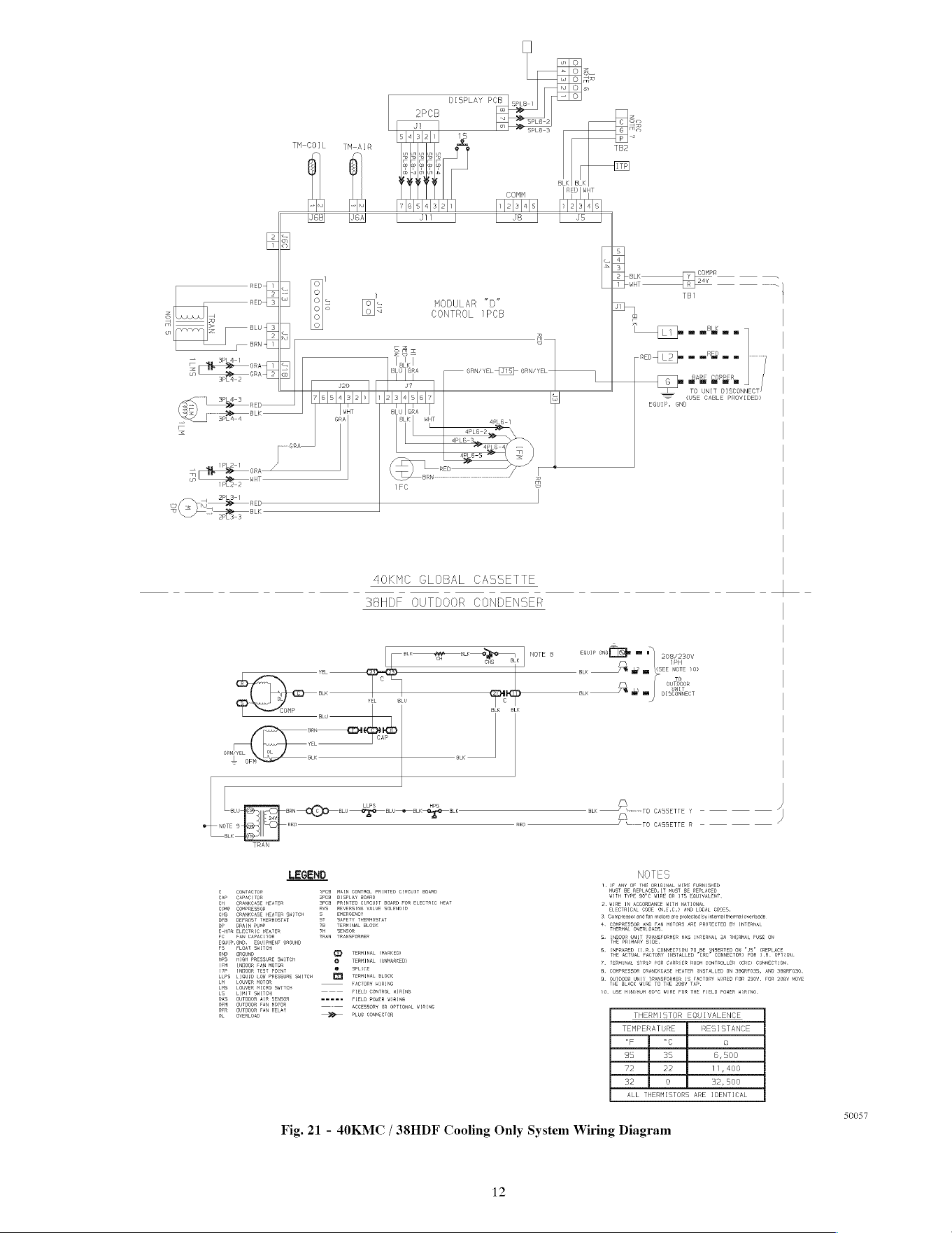
50057
Fig.
21
-
40K
MC
/
38HDF
Cooling
Only
System
Wiring
Diagram
IL
TM-AIR
ake
—8]0—
v/
YELLS
GRN/YEL:
cS
aLK
BLK
BLK
$
He
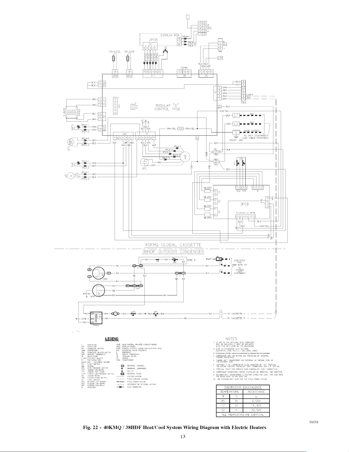
Fig.
22
-
40KMQ
/
38HDF
Heat/Cool
System
Wiring
Diagram
with
Electric
Heaters
LL:
s
PO
PL
—9—
BL
bag
aL
RATIONAL,
zc
AND
LOCAL
Ci
3.
Compressor
and
fan
motors
are
protected
by
intemal
thermal
averloads.
4.
conpne:
AND FAN
HOTORS
ARE
PROTEC
ALO
cOMPRE
NSFORMER
HAS
INTERNAL
24
THERON,
FUSE
08
TEMPERATURE
oF of
50058
13
L
ALON
OW
COMM
or
RAYEL
ate
[Tf
om
ah
ee
a
3
BLON
ORR/YEL
GRN/YEL:
LECHTa
HO]
o}"
2E-HTR
xe
SEHTR
8
LEL2L2
LI
PE
PE
4E-HTR
POGO9OD
BLK
pee
|
|
OL
ceneveL--
| T
: |
I
¢
CHR,
CORES,
joressor
and
fan
plotors
are
protected
by
internal
thermal
overloads,
MPRESEOR
AND
FAN
MOTORS
ARE
PROTECTED
BY
INTERNAL
INPERNAL,
25
THERMAL
TERMINAL
GYARKED?
TERHINSL
GRBARKED?
WIRERS
OPPLONAL
WERING
TEMPERATURE
°F
1cal
Fig.
23
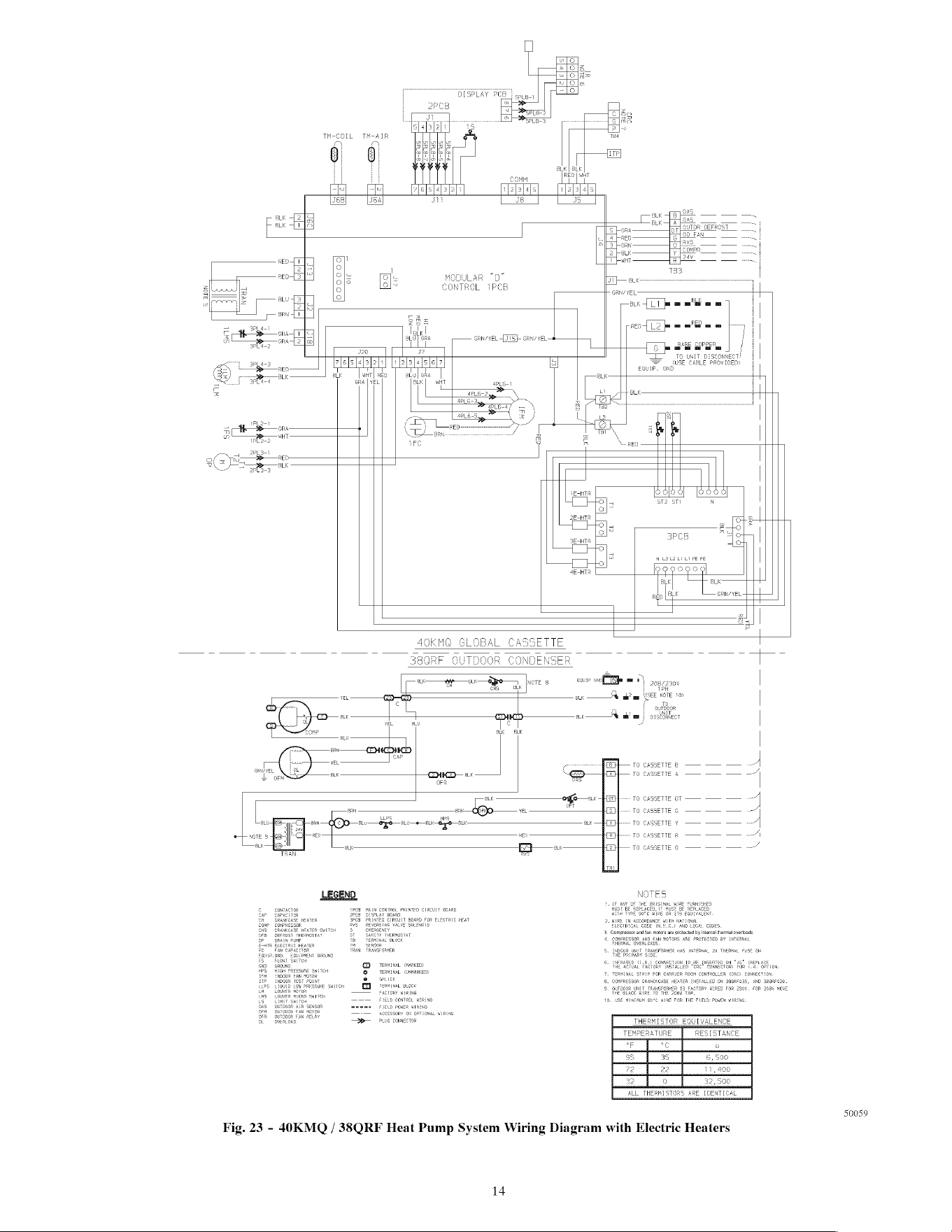
-
40KMQ
/
38QRF
Heat
Pump
System
Wiring
Diagram
with
Electric
Heaters
14
Run Power
Wiring
for
Indoor
Unit
Be
sure
field
wiring
complies
with
local
building
codes
and
NEC,
and
unit
voltage
is
within
limits
shown
in
Table
11
and
Table
12.
Contact
local
power
company
for
correction
of
improper
line
voltage.
ELECTRICAL
SHOCK
HAZARD
Failure
to
follow
this
warning
could
result
in
personal
injury
or
death.
Before
installing,
modifying,
or
servicing
system,
main
electrical
disconnect
switch
must
be
in
the
OFF
position.
There
may
be
more
than
1
disconnect
switch.
Lock
out
and
tag
switch
with
a
suitable
warning
label.
UNIT
DAMAGE
HAZARD
Failure
to
follow
this
caution
may
result
in
equipment
damage
or
improper
operation.
Unit
failure
as
a
result
of
operation
on
improper
line
voltage
or
excessive
phase
imbalance
constitutes
abuse
and
may
cause
damage
to
electrical
components.
Such
operation
could
void
any
applicable
Carrier
warranty.
NOTE:
Use
copper
wire
only
between
disconnect
switch(es)
and
unit.
NOTE:
Install
branch
circuit
disconnect
of
adequate
size
to
handle
unit
starting
current
per
NEC.
Locate
disconnect
within
sight
of,
and
readily
accessible
from,
unit,
per
section
440-14
of
NEC.
Some
codes
allow
indoor
unit
to
share
disconnect
with
outdoor
unit
if
disconnect
can
be
locked;
check
local
code
before
installing
in
this
manner.
The
40KMC/KMO
units
require
their
own
power
supply.
1.
Locate
the
indoor
power
supply.
2.
Locate
and
install
disconnect
switch
per
NEC
and
local
codes.
3.
Run
power
supply
wiring
to
disconnect
switch.
4.
Run
power
wiring
from
disconnect
switch
to
control
box
area,
Use
copper
wire only
between
the
disconnect
switch
and
unit.
Use
minimum
60°C
wires
for
field
power
con-
nection.
5.
Remove
the
external
control
box
cover.
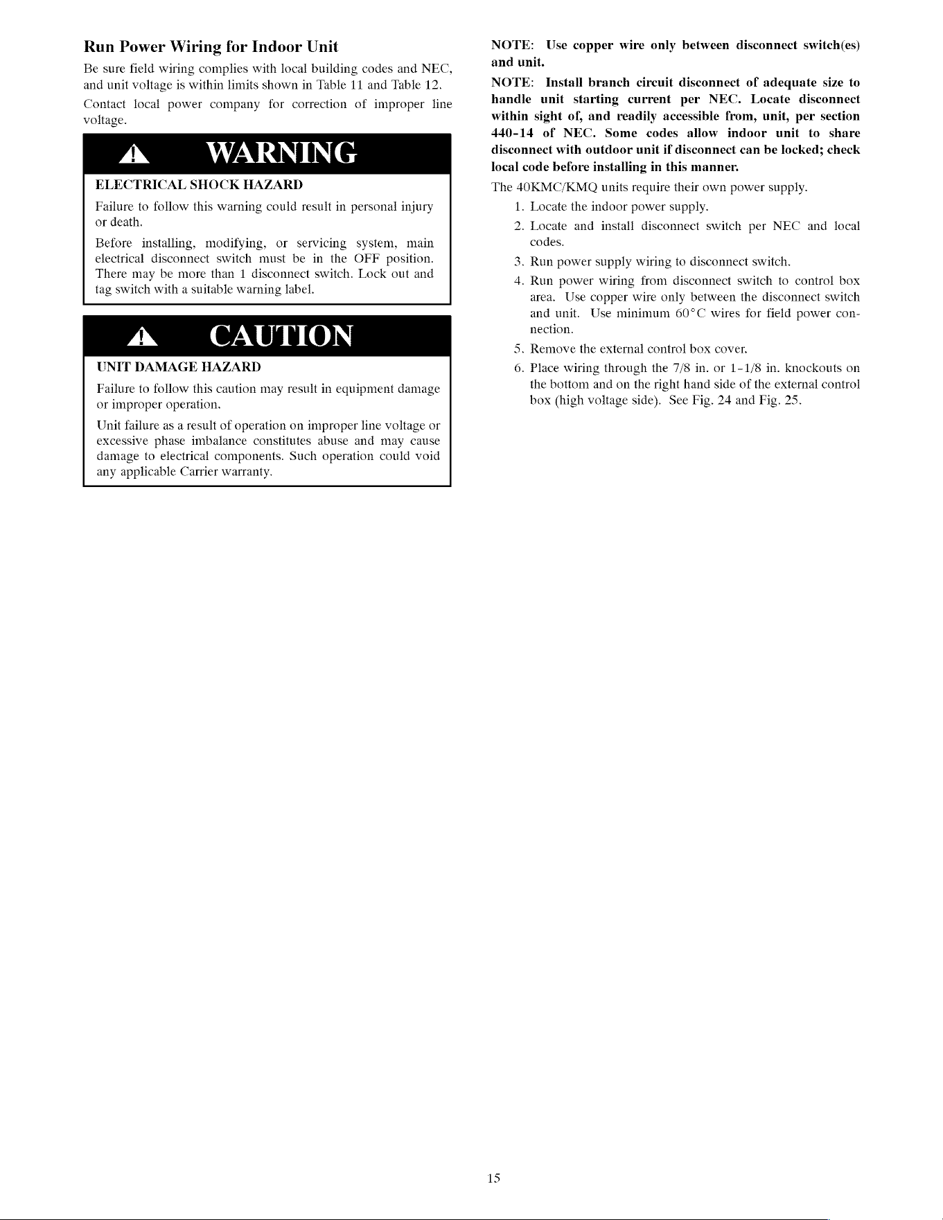
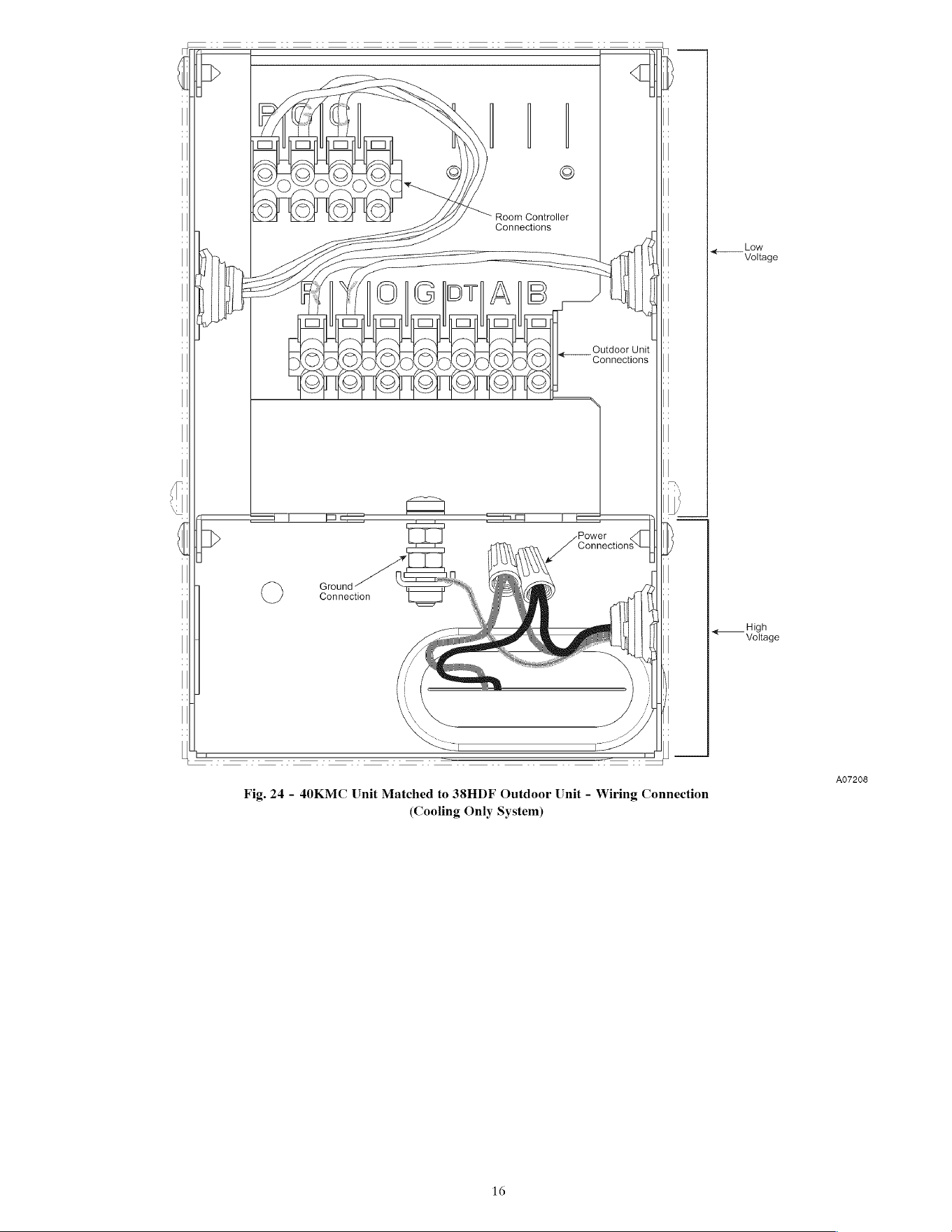
6.
Place
wiring
through
the
7/8
in.
or
1-1/8
in.
knockouts
on
the
bottom
and
on
the
right
hand
side
of
the
external
control
box
(high
voltage
side).
See
Fig.
24
and
Fig.
25.
15
Room
Controller
| |
Connections
| |
<—Veltage
foley
Ae
Outdoor
Unit
||"
Connections
| |
|
CI
VN
y—oN
|
Os@OsOsOsOs©ce
:
OnCniCnenenene
boc;
—a
ri
I
| |
Ground
tt
C)
Connection
| |
<——_
Voltage
A07208
Fig.
24
-
40KMC
Unit
Matched
to
33HDF
Outdoor
Unit
-
Wiring
Connection
(Cooling
Only
System)
16
(
>
aft
! !
Solio
| |
7
OWS)
og
"
| |
S
©
2
oo!
| |
:
©
©
©
©
Room
Controller
m
| |
Connections
| |
|
|
|
|
<—\
Stage
I
|
IG
|
'
EI
CI
EI EI
CI
CE)
EI
'
|
|
ms
(
Outdoor
Unit
|
o
|
QOIODAOQAIOD
AOA
OIA
SO
Connections
1
| |
OCTNTIT
TROT
TET
TET
he
| |
I
|
|
I,
‘i
oa
J
p>
lll
{|
U
Connections
U
|
| |
seme“
| |
C)
Connection
os
|
|
|
|
|
|
|
<—
Valage
LL
i=
|
||
A07209
Fig.
25
-
40KMQ
Unit
Matched
to
383HDF
Outdoor
Unit
-
Wiring
Connection
(Cooling
with
Electric
Heat
System)
17
7.
Connect
L1
to
the
black
wire
and
L2
to
the
red
wire
using
wire
nuts
and
fix
the
ground
wire
between
the
two
washers.
The
internal
control
panel
can
be
accessed
by
opening
the
grille
and
removing
the
metal
cover
attached
by
four
screws.
NOTE:
The
internal
control
panel
does
not
need
to
be
accessed
during
the
installation
process
unless
there
is
a
need
for
service.
8.
If
any
accessories
are
being
installed,
refer
to
the
individual
accessory
instructions
for
guidance
on
wire
routing
at
this
time.
Install
All
Power,
Interconnecting
Wiring,
Piping
and
Drain
Hose
to
Indoor
Unit
.
1.
Run
control
wiring
from
the
outdoor
unit
through
the
access
hole
in
the
wall
and
make
sure
you
have
enough
wire
to
reach
the
control
box
of
the
unit
once
hung
on
the
mounting
plate.
bo
.
Complete
refrigerant
piping
connections.
a.
cut the
extreme
end
of
the
tubes
and
remove
any
copper
shavings
with
a
de-burring
blade.
b.
Remove
the
flare
nut
from
the
“Flare”
connection
body
of
the
indoor
unit
and
insert
them
into
the
pipes.
c.
make
the
flares
to
the
pipe
ends
with
the
proper
flaring
too.
The
flare
end
must
not
have
any burrs
or
imperfec-
tions.
the
flared
walls
must
be
uniform.
See
Fig.
26
and
Fig.
27.
A07L99
Fig.
26
-
Removing
Burrs
Vv
07200
Fig.
27
-
Flared
Walls
are
Equal
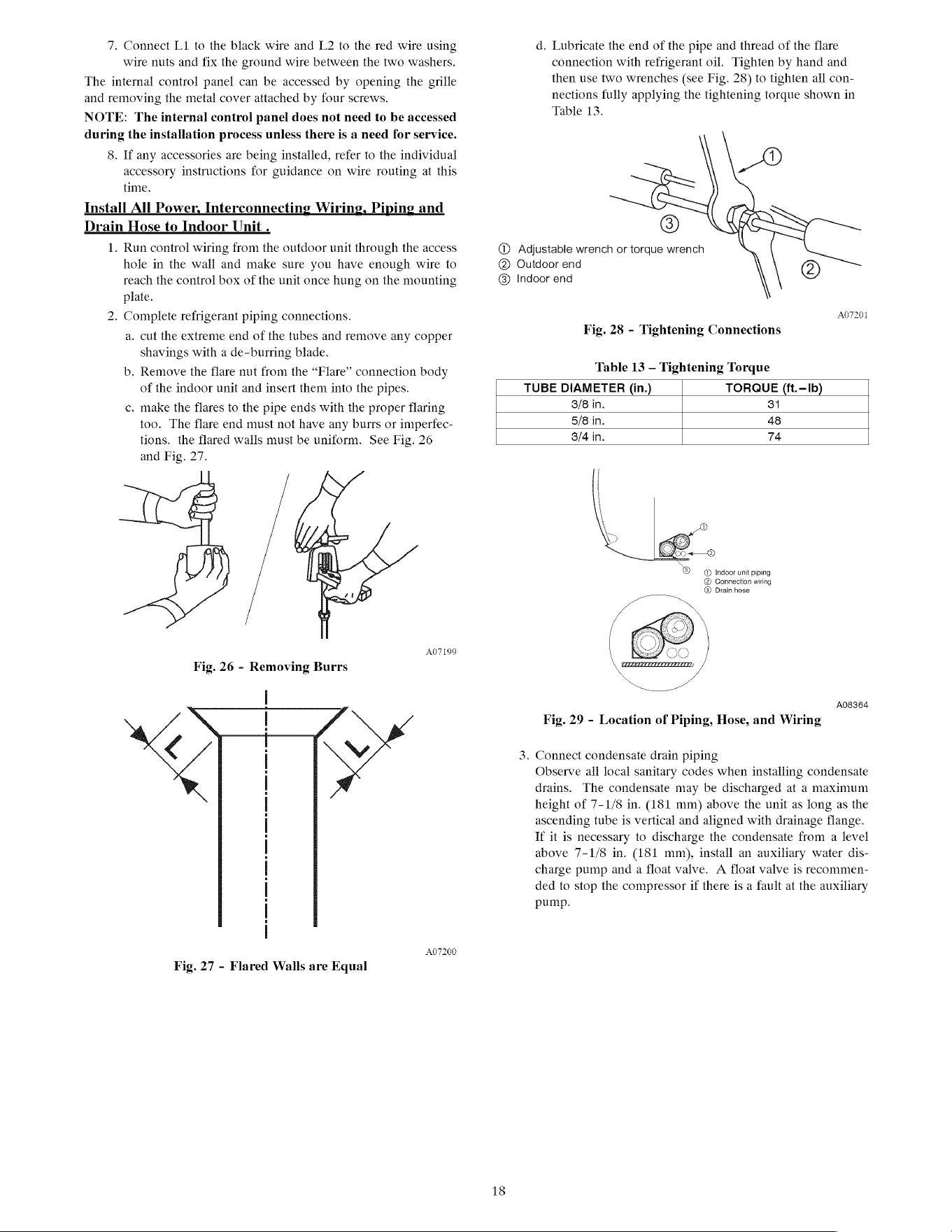
d.
Lubricate
the
end
of
the
pipe
and
thread
of
the
flare
connection
with
refrigerant
oil.
Tighten
by
hand
and
then
use
two
wrenches
(see Fig.
28)
to
tighten
all
con-
nections
fully
applying
the
tightening
torque
shown
in
Table
13.
@
0)
Adjustable
wrench
or
torque
wrench
@
Outdoor
end
@
@
Indoor
end
A07201
Fig.
28
-
Tightening
Connections
Table
13
—
Tightening
Torque
TUBE
DIAMETER
(in.)
TORQUE
(ft.—Ib)
3/8
in.
31
5/8
in.
48
3/4
in.
74
@
Indoor
unit
piping
@
Connection
wiring
@®
Drain
hose
A08ae4
Fig.
29
-
Location
of
Piping,
Hose,
and
Wiring
3.
Connect
condensate
drain
piping
Observe
ail
local
sanitary
codes
when
installing
condensate
drains.
The
condensate
may
be
discharged
at
a
maximum
height
of
7-1/8
in.
(181
mm)
above
the
unit
as
long
as
the
ascending
tube
is
vertical
and
aligned
with
drainage
flange.
If
it
is
necessary
to
discharge
the
condensate
from a
level
above
7-1/8
in.
(181
mm),
install
an
auxiliary
water
dis-
charge
pump
and
a
float
valve.
A
float
valve
is
recommen-
ded
to
stop
the
compressor
if
there
is
a
fault
at
the
auxiliary
pump.
18
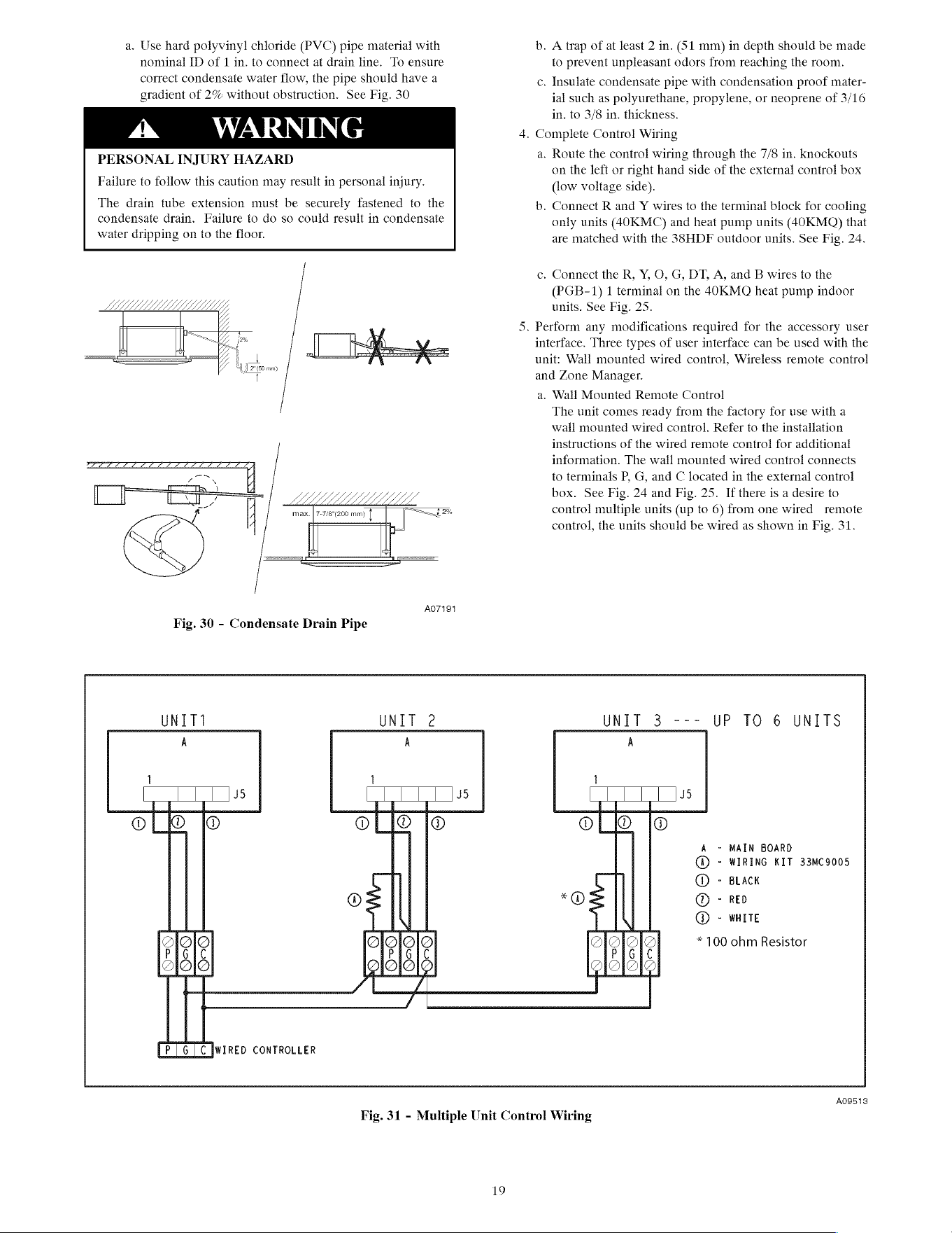
a.
Use
hard
polyvinyl
chloride
(PVC)
pipe
material with
nominal
ID
of
1
in.
to
connect
at
drain
line.
To
ensure
correct
condensate
water
flow,
the
pipe
should
have
a
gradient
of
2%
without
obstruction.
See
Fig.
30
PERSONAL
INJURY
HAZARD
Failure
to
follow
this
caution
may
result
in
personal
injury.
The
drain
tube
extension must
be
securely
fastened
to
the
condensate
drain.
Failure
to
do
so
could
result
in
condensate
water
dripping
on
to
the
floor.
LM
G
WL
J,
é
’
H
max.
|
7-7/8"(200
mm)
|
J
22%
iP
dh
ih
b.
a.
b.
A
trap
of
at
least
2
in.
(51
mm)
in
depth
should
be
made
to
prevent
unpleasant
odors
from
reaching
the
room.
.
Insulate
condensate
pipe
with
condensation
proof
mater-
ial
such
as
polyurethane,
propylene,
or
neoprene
of
3/16
in.
to
3/8
in.
thickness.
.
Complete
Control
Wiring
Route
the
control
wiring
through
the
7/8
in.
knockouts
on
the
left
or
right
hand
side
of
the
external
control
box
(low
voltage
side).
Connect
R
and
Y wires
to
the
terminal
block
for
cooling
only
units
(40KMC)
and
heat
pump
units
(40KMQ)
that
are
matched
with
the
383HDF
outdoor
units.
See
Fig.
24.
.
Connect
the
R,
Y,
O, G,
DT,
A,
and
B
wires
to
the
(PGB-1)
1
terminal
on
the
4OKMOQ
heat
pump
indoor
units.
See
Fig.
25.
.
Perform
any
modifications
required
for
the
accessory
user
interface.
Three
types
of
user
interface
can
be
used
with
the
unit:
Wall
mounted
wired
control,
Wireless
remote
control
and
Zone Manager.
a.
Wall
Mounted
Remote
Control
The
unit
comes
ready
from
the
factory
for
use
with
a
wall
mounted
wired
control.
Refer
to
the
installation
instructions
of
the
wired
remote
control
for
additional
information.
The
wall
mounted
wired
contro!
connects
to
terminals
P,
G,
and
C
located
in
the
external
control
box.
See
Fig.
24
and
Fig.
25.
If
there
is
a
desire
to
control
multiple
units
(up
to
6)
from
one
wired
remote
control,
the
units
should
be
wired
as
shown
in
Fig.
31.
AO7194
Fig.
30
-
Condensate
Drain
Pipe
UNIT1
UNIT
2
UNIT
3
---
UP
TO
6
UNITS
A A A
O2@
Se
929
9eQ
POe@
©
PO
_OF-W-
~
MAIN
BOARD
-
WIRING
KIT
33mMC9005
-
BLACK
-
RED
~
WHITE
CICIOIOr.
*
100
ohm
Resistor
QeQ
929
WN
(P16)
[WIRED
CONTROLLER
A09513
Fig.
31
-
Multiple
Unit
Control
Wiring
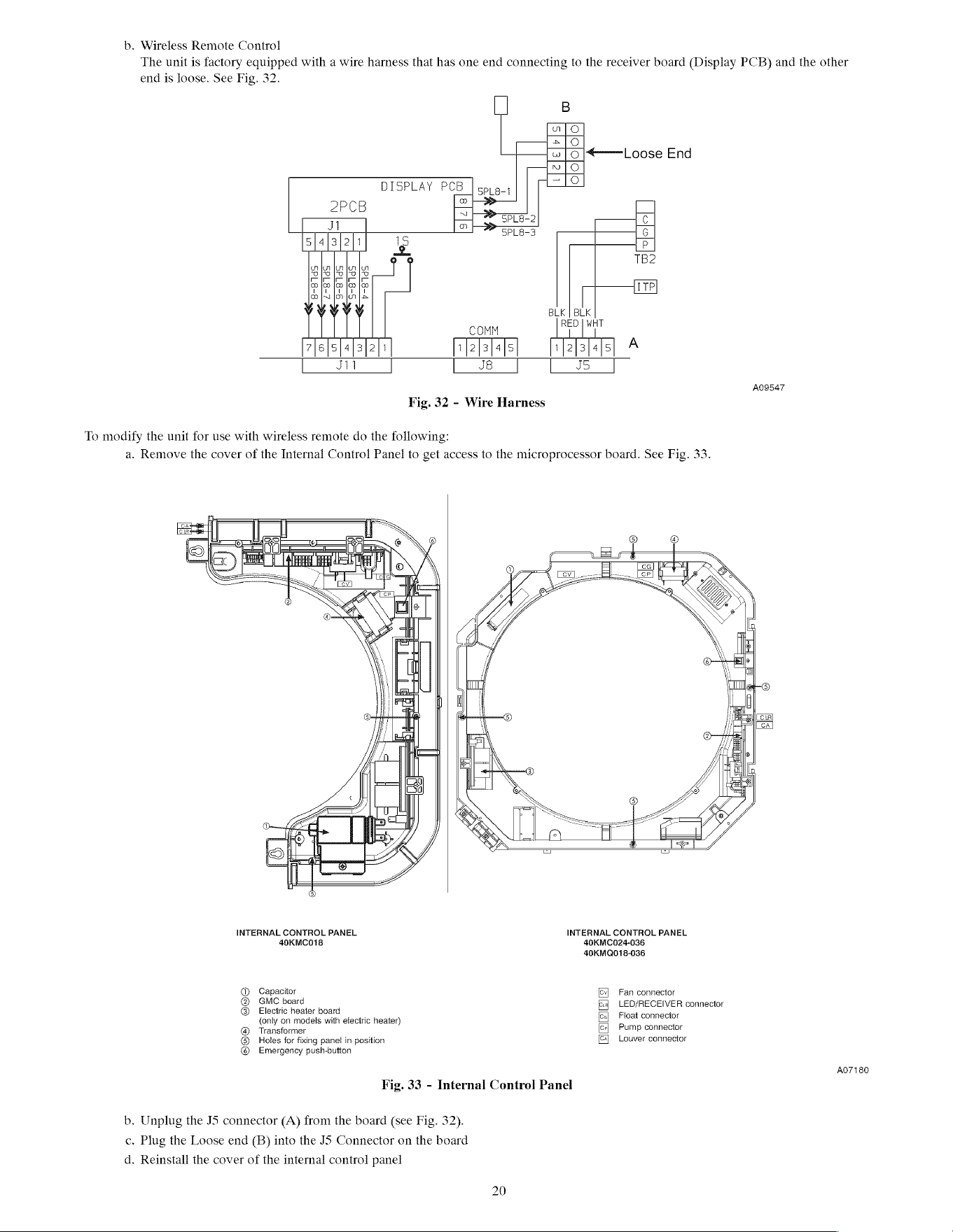
b.
Wireless
Remote
Control
The
unit
is
factory
equipped
with
a
wire
harness
that
has
one end
connecting
to
the
receiver
board
(Display
PCB)
and
the
other
end
is
loose.
See
Fig.
32.
B
alo
&|O
wlol|*
Loose
End
nN}
O
DISPLAY
PCB
|cpip-y
“12
ob}
5—
2Pcb
~
3
SpLE-2
C
JI
2
|
Spans
6
s[4]3]2|i
1S
B
TB2
gigigisig
ee
Rte
+
HIN
[MH
1M
|
@Lk
|
BLK
LITT
COMM
ia
7|6]s]4]al2|1
']2]3]als
1f2[a]4]s
Ji
J8
J5
A09547
Fig.
32
-
Wire
Harness
To
modify
the
unit
for
use
with
wireless
remote
do
the
following:
a.
Remove
the
cover
of
the
Internal
Control
Panel
to
get
access
to
the
microprocessor
board.
See
Fig.
33.
ee
=
=
INTERNAL
CONTROL
PANEL
INTERNAL
CONTROL
PANEL
40KMCO18
40KMC024-036
40KMQ018-036
Capacitor
GMC
board
Electric
heater
board
{only on
models
with electric
heater)
Transformer
Holes
for
fixing
panel
in
position
Emergency
push-button
Fan
connector
LED/RECEIVER
connector
Float
connector
Pump
connector
Louver
connector
€890
©o®
A07180
Fig.
33
-
Internal
Contro!
Panel
b.
Unplug
the
JS
connector
(A)
from
the
board
(see Fig. 32).
c.
Plug
the
Loose
end
(B)
into
the
JS
Connector
on
the
board
d.
Reinstall
the
cover
of
the
internal
control
panel
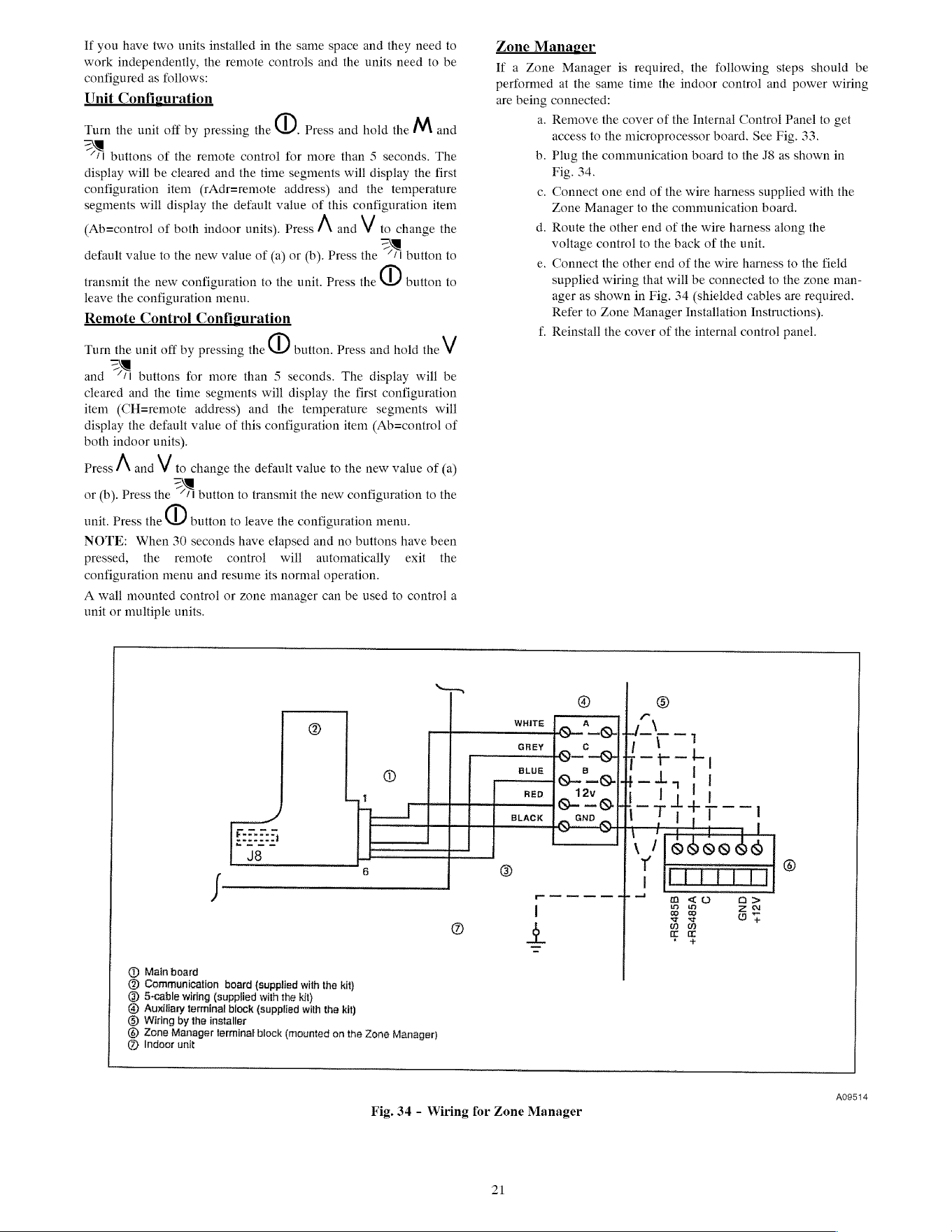
If
you
have
two
units
installed
in
the
same
space
and
they
need
to
work
independently,
the
remote
controls
and
the
units
need
to
be
configured
as
follows:
Unit
Configuration
Turn
the
unit
off
by
pressing
the
O}
Press
and
hold
the
M
and
A
buttons
of
the
remote
control
for
more
than
5
seconds.
The
display
will
be
cleared
and
the
time
segments
will
display
the
first
configuration
item
(rAdr=remote
address)
and
the
temperature
segments
will
display
the
default
value
of
this
configuration
item
(Ab=control
of
both
indoor
units).
Press
A
and
V
to
change
the
oN
default
value
to
the
new
value
of
(a)
or
(b).
Press
the
“/1
button
to
transmit
the
new
configuration
to
the
unit.
Press
the
®
button
to
leave
the
configuration
menu.
Remote
Control
Configuration
Turn
the
unit
off
by
pressing
the
®
button.
Press
and
hold
the
V
and
A
buttons
for
more
than
5
seconds.
The
display
will
be
cleared
and
the
time
segments
will
display
the
first
configuration
item
(CH=remote
address)
and
the
temperature
segments
will
display
the
default
value
of
this
configuration
item
(Ab=control
of
both
indoor
units).
Press
A
and
V
to
change
the
default
value
to
the
new
value
of
(a)
oN
or
(b).
Press
the
“/I
button
to
transmit
the
new
configuration
to
the
unit.
Press
the
®
button
to
leave
the
configuration
menu.
NOTE:
When
30
seconds
have
elapsed
and
no
buttons
have
been
pressed,
the
remote
control
will
automatically
exit
the
configuration
menu
and
resume
its
normal
operation.
A
wall
mounted
control
or
zone
manager
can
be
used
to
control
a
unit
or
multiple
units.
Zone
Manager
If
a
Zone
Manager
is
required,
the
following
steps
should
be
performed
at
the
same
time
the
indoor
control
and
power
wiring
are
being
connected:
a.
Remove
the
cover
of
the
Internal
Control
Panel
to
get
access
to
the
microprocessor
board.
See
Fig.
33.
b.
Plug
the
communication
board
to
the
J8
as
shown
in
Fig.
34.
c.
Connect
one end
of
the
wire
harness
supplied
with
the
Zone
Manager
to
the
communication
board.
d.
Route
the
other
end
of
the
wire
harness
along
the
voltage
control
to
the
back
of
the
unit.
e.
Connect
the
other
end
of
the
wire
harness
to
the
field
supplied
wiring
that
will
be
connected
to
the
zone
man-
ager
as
shown
in
Fig.
34
(shielded
cables
are
required.
Refer
to
Zone
Manager
Installation
Instructions).
f.
Reinstall
the
cover
of
the
internal
control
panel.
@
Main
board
@
Communication
board
(supplied
with
the
kit)
@
5-cable
wiring
(supplied
with
the
kit)
@
Auxillary
terminal
block
(supplied
with
the
kit)
©)
Wiring
by
the
installer
@
Zone
Manager
terminal
block
(mounted
on
the
Zone
Manager)
@
Indoor
unit
Seer
@
®
WHITE
A
c
®
H—
—S-|-
71
GREY
9-9]
pak,
8
@
BLUE
e-—el4—1,
|
neo
lh
tata
__]
BLACK
GND
!
i
i |
\
/1989908e
A
®
T
=
©
;
|LLT
TTT
Pe
meee
ce
cme
moe
ph
ma
<0
o>
@
4
22
A09514
Fig.
34
-
Wiring
for
Zone
Manager
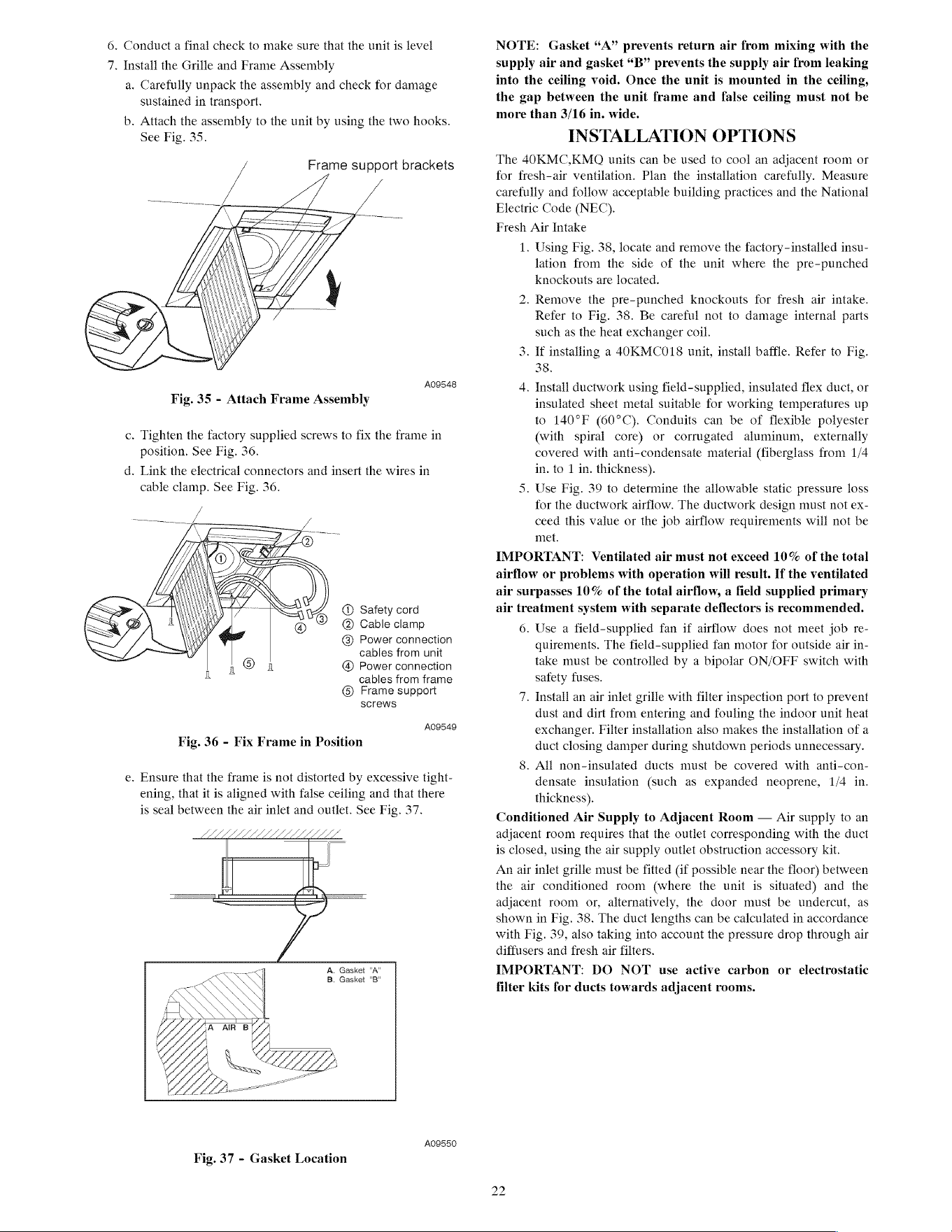
6.
Conduct
a
final
check
to
make
sure
that
the
unit
is
level
7.
Install
the
Grille
and
Frame
Assembly
a.
Carefully
unpack
the
assembly
and
check
for
damage
sustained
in
transport.
b.
Attach
the
assembly
to
the
unit
by
using
the
two
hooks.
See
Fig.
35.
Frame
support
brackets
A09548
Fig.
35
-
Attach
Frame
Assembly
c.
Tighten
the
factory
supplied
screws
to
fix
the
frame
in
position.
See
Fig.
36.
d.
Link
the
electrical
connectors
and
insert
the
wires
in
cable
clamp.
See
Fig.
36.
@
Safety
cord
@
Cable
clamp
@
Power
connection
cables
from
unit
@®
Power
connection
cables
from
frame
®
Frame
support
screws
A09549
Fig.
36
-
Fix
Frame
in
Position
e.
Ensure
that
the
frame
is
not
distorted
by
excessive
tight-
ening,
that
it
is
aligned
with
false
ceiling
and
that
there
is
seal
between
the
air
inlet
and
outlet.
See
Fig.
37.
LLL
A.
Gasket
"A"
B.
Gasket
"B"
A09550
Fig.
37
-
Gasket
Location
NOTE:
Gasket
“A”
prevents
return
air
from
mixing
with
the
supply
air
and
gasket
“B”
prevents
the
supply
air
from
leaking
into
the
ceiling
void.
Once
the
unit
is
mounted
in
the
ceiling,
the
gap
between
the
unit
frame
and
false
ceiling
must
not
be
more
than
3/16
in.
wide.
INSTALLATION
OPTIONS
The
40KMC,KMO
units
can
be
used
to
cool
an
adjacent
room
or
for
fresh-air
ventilation.
Plan
the
installation
carefully.
Measure
carefully
and
follow
acceptable
building
practices
and
the
National
Electric
Code
(NEC).
Fresh
Air
Intake
1.
Using
Fig.
38,
locate
and
remove
the
factory-installed
insu-
lation
from
the
side
of
the
unit
where
the
pre-punched
knockouts
are
located.
bo
.
Remove
the
pre-punched
knockouts
for
fresh
air
intake.
Refer
to
Fig.
38.
Be
careful
not
to
damage
internal
parts
such
as
the
heat
exchanger
coil.
3. If
installing
a
4OKMCO018
unit,
install
baffle.
Refer
to
Fig.
38.
4.
Install
ductwork
using
field-supplied,
insulated
flex
duct,
or
insulated
sheet
metal
suitable
for
working
temperatures
up
to
140°F
(60°C).
Conduits
can
be
of
flexible
polyester
(with
spiral
core)
or
corrugated
aluminum,
externally
covered
with
anti-condensate
material
(fiberglass
from
1/4
in.
to
1
in.
thickness).
5.
Use
Fig.
39
to
determine
the
allowable
static
pressure
loss
for
the
ductwork
airflow.
The
ductwork
design
must
not
ex-
ceed
this
value
or
the
job
airflow
requirements
will
not
be
met.
IMPORTANT:
Ventilated
air
must
not
exceed
10%
of
the
total
airflow
or
problems
with
operation
will
result.
If
the
ventilated
air
surpasses
10%
of
the
total
airflow,
a
field
supplied
primary
air
treatment
system
with
separate
deflectors
is
recommended.
6.
Use
a
field-supplied
fan
if
airflow
does
not
meet
job
re-
quirements.
The field-supplied
fan
motor
for
outside
air
in-
take
must
be
controlled
by
a
bipolar
ON/OFF
switch
with
satety
fuses.
7.
Install
an
air
inlet
grille
with
filter
inspection
port
to
prevent
dust
and
dirt
from
entering
and
fouling
the
indoor
unit
heat
exchanger.
Filter
installation
also
makes
the
installation
of
a
duct
closing
damper
during
shutdown
periods
unnecessary.
8.
All
non-insulated
ducts
must
be
covered
with
anti-con-
densate
insulation
(such
as
expanded
neoprene,
1/4
in.
thickness).
Conditioned
Air
Supply
to
Adjacent
Room
—
Air
supply
to
an
adjacent
room
requires
that
the
outlet
corresponding
with
the
duct
is
closed,
using
the
air
supply
outlet
obstruction
accessory
kit.
An
air
inlet
grille
must
be
fitted
(if
possible
near
the
floor)
between
the
air
conditioned
room
(where
the
unit
is
situated)
and
the
adjacent
room
or,
alternatively,
the
door
must
be
undercut,
as
shown
in
Fig.
38.
The
duct
lengths
can
be
calculated
in
accordance
with
Fig.
39, also
taking
into
account
the
pressure
drop
through
air
diffusers
and
fresh
air
filters.
IMPORTANT:
DO
NOT
use
active
carbon
or
electrostatic
filter
kits
for
ducts
towards
adjacent
rooms.
bo
bo
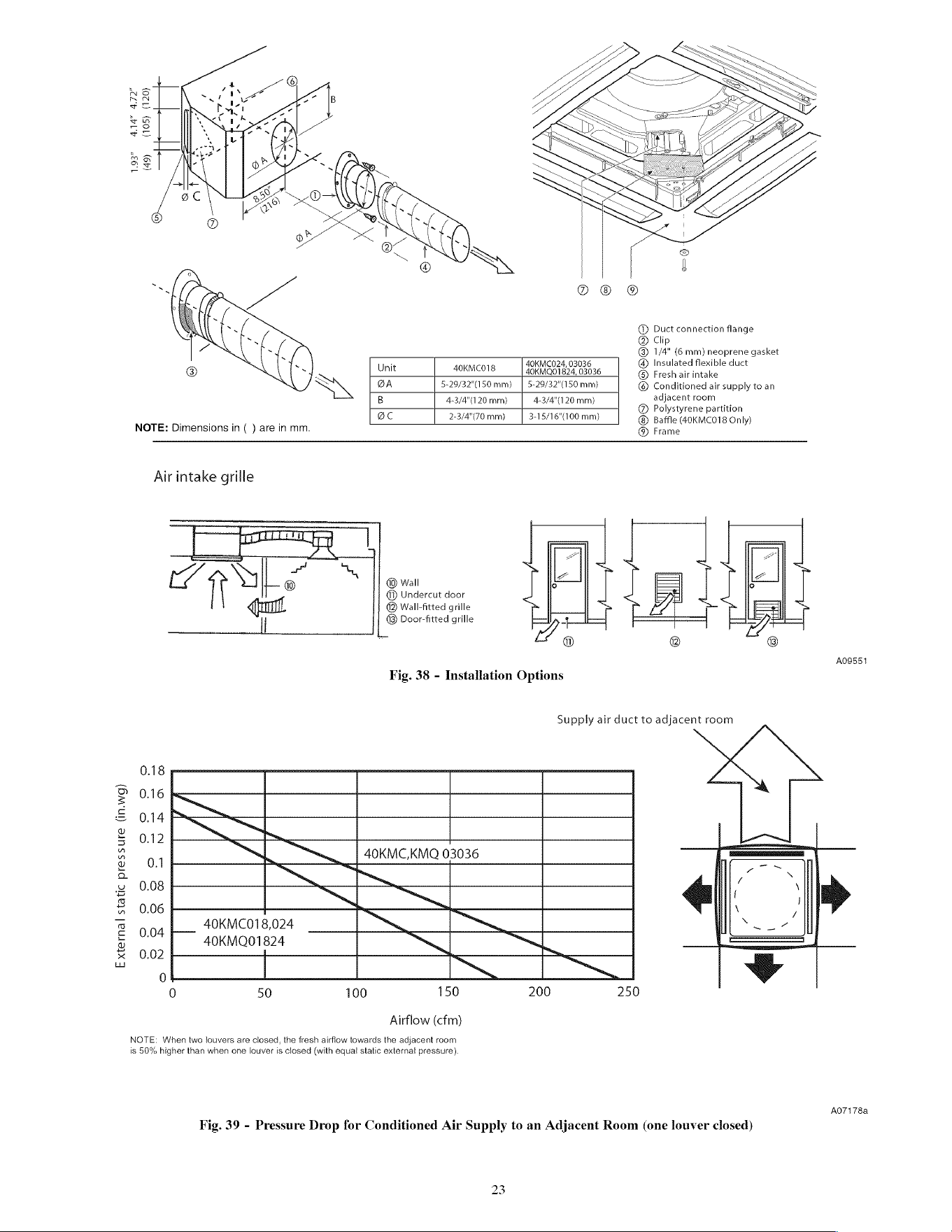
External
static
pressure
(in.wg)
4.14"
4.72
(105)
(120)
1.93
(49)
@
Duct
connection
flange
®
Clip
@®
1/4”
(6
mm)
neoprene
gasket
40KMC024,
03036
@®
Insulated
flexible
duct
®
Fresh
air
intake
©
Conditioned
air
supply
to
an
adjacent
room
Unit
40KMCO18
40KMOQ01824,
03036
BA
5-29/32"(150
mm)
|
5-29/32"(150
mm)
B
4-3/4"(120
mm)
4-3/4"(120
mm)
oC
2-3/4"(70
mm)
|
3+15/16"(100
mm)
@
Polystyrene
partition
Baffle
(40KMC018
Only)
NOTE:
Dimensions
in
( )
are
in
mm.
@®
Frame
Air
intake
grille
tH
ie
Tl
ea
@
Undercut
door
@®
Wall-fitted
grille
Tl
®
Door-fitted
grille
Fig.
38
-
Installation
Options
0.18
0.16
0.14
0.12
40KMC,KMQ
03036
0.1
0.08
0.06
0.04
0.02
40KMC018,024
40KMQ01824
0
50
100
150
Airflow
(cfm)
NOTE:
When
two
louvers
are
closed,
the
fresh
airflow
towards
the
adjacent
room
is
50%
higher
than
when
one
louver
is
closed
(with
equal
static
external
pressure).
A0G9551
Supply
air
duct
to
adjacent
room
200
250
AO7178a
Fig.
39
-
Pressure
Drop
for
Conditioned
Air
Supply
to
an
Adjacent
Room
(one
louver
closed)
bo
on
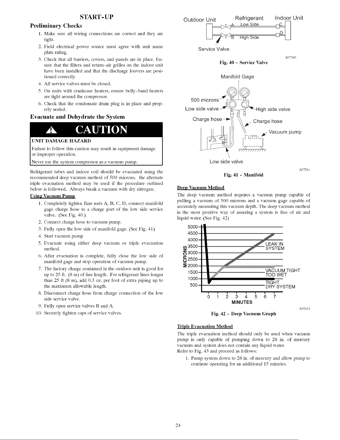
START-UP
Preliminary
Checks
1.
Make
sure
all
wiring
connections
are
correct
and
they
are
tight.
.
Field
electrical
power
source
must
agree
with
unit
name
plate rating.
bo
3.
Check
that
all
barriers,
covers, and
panels
are
in
place.
En-
sure
that
the
filters
and
return-air
grilles
on
the
indoor
unit
have
been
installed
and
that
the
discharge
louvers
are
posi-
tioned
correctly.
4.
All
service
valves
must
be
closed.
5.
On
units
with
crankcase
heaters,
ensure
belly-band
heaters
are
tight
around
the
compressor.
6.
Check
that
the
condensate
drain
plug
is
in
place
and
prop-
erly
sealed.
Evacuate
and
Dehydrate
the
System
UNIT
DAMAGE
HAZARD
Failure
to
follow
this
caution
may
result
in
equipment
damage
or
improper
operation.
Never
use
the
system
compressor
as
a
vacuum
pump.
Refrigerant
tubes
and
indoor
coil
should
be
evacuated
using
the
recommended
deep
vacuum
method
of
500
microns.
the
alternate
triple
evacuation
method
may
be
used
if
the
procedure
outlined
below
is
followed.
Always
break
a
vacuum
with
dry
nitrogen.
Using
Vacuum
Pump
1.
Completely
tighten
flare
nuts
A,
B,
C,
D,
connect
manifold
gage
charge
hose
to
a
charge
port
of
the
low
side
service
valve.
(See
Fig.
40.)
.
Connect
charge
hose
to
vacuum
pump.
Ww
be
.
Fully
open
the
low
side
of
manifold
gage.
(See
Fig.
41)
.
Start
vacuum
pump
a
.
Evacuate
using
either
deep
vacuum
or
triple
evacuation
method.
6.
After
evacuation
is
complete,
fully
close
the
low
side
of
manifold
gage
and
stop
operation
of
vacuum
pump.
~l
.
The
factory
charge
contained
in
the
outdoor
unit
is
good
for
up
to
25
ft.
(8
m)
of
line
length.
For
refrigerant
lines
longer
than
25
ft
(8
m),
add
0.3
oz.
per
foot
of
extra
piping
up
to
the
maximum
allowable
length.
8.
Disconnect
charge
hose
from
charge
connection
of
the
low
side
service
valve.
oO
.
Fully
open
service
vaives
B
and
A.
10.
Securely
tighten
caps
of
service valves.
Refrigerant
Indoor
Unit
Low
Side
Outdoor
Unit
Service
Valve
07360
Fig.
40
-
Service
Valve
Manifoid
Gage
500
microns~*
-e-1
Rap
High
side
vaive
Charge
hose
ll
°
Low
side
vaive
-
Charge
hose
-
Vacuum
pump
Low
side
valve
A07361
Fig.
41
-
Manifold
Deep Vacuum
Method
The
deep
vacuum
method
requires
a
vacuum
pump
capable
of
pulling
a
vacuum
of
500
microns
and
a
vacuum
gage
capable
of
accurately
measuring
this
vacuum
depth.
The
deep
vacuum
method
is
the
most
positive
way
of
assuring
a
system
is
free
of
air
and
liquid
water.
(See
Fig.
42)
50004
4500
4
g
S500
Z
SYSTEM
6
3000-
oc
6
2500
= 2000-44
=
a
VACUUM
TIGHT
‘ooo
TOO
WET
TIGHT
500
———__—_———
pry
SYSTEM
MINUTES
A95424
Fig.
42
-
Deep
Vacuum
Graph
Triple
Evacuation
Method
The
triple
evacuation
method
should
only
be
used
when
vacuum
pump
is
only
capable
of
pumping
down
to
28
in.
of
mercury
vacuum
and
system
does
not
contain
any
liquid
water.
Refer
to
Fig.
43
and
proceed
as
follows:
1.
Pump
system
down
to
28
in.
of
mercury
and
allow
pump
to
continue
operating
for
an
additional
15
minutes.
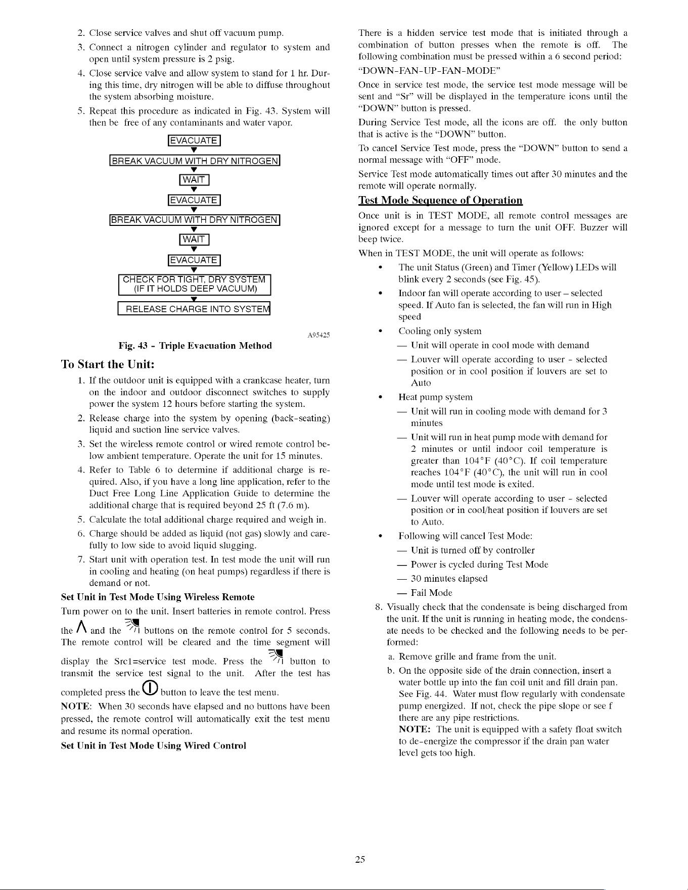
.
Close
service
valves
and
shut
off
vacuum
pump.
Ww
.
Connect
a
nitrogen
cylinder
and
regulator
to
system
and
open
until
system
pressure
is
2
psig.
4.
Close
service
valve
and
allow
system
to
stand
for
1
hr.
Dur-
ing
this
time,
dry
nitrogen
will
be
able
to
diffuse
throughout
the
system
absorbing
moisture.
5.
Repeat
this
procedure
as
indicated
in
Fig.
43.
System
will
then
be
free
of
any
contaminants
and
water
vapor.
EVACUATE
Vv
[BREAK
VACUUM
WITH
DRY
NITROGEN}
Vv
[WAIT]
[EVACUATE]
Vv
JBREAK
VACUUM
WITH
DRY
NITROGEN]
Vv
Vv
EVACUATE
Vv
CHECK
FOR
TIGHT,
DRY
SYSTEM
(IF
IT
HOLDS
DEEP
VACUUM)
5
<
v
|
RELEASE
CHARGE
INTO
SYSTEM
Fig.
43
-
Triple
Evacuation
Method
To
Start
the
Unit:
1.
If
the
outdoor
unit
is
equipped
with
a
crankcase
heater,
turn
on
the
indoor
and
outdoor
disconnect
switches
to
supply
power
the
system
12
hours
before
starting
the
system.
bo
.
Release
charge
into
the
system
by
opening
(back-seating)
liquid
and
suction
line
service valves.
3.
Set
the
wireless
remote
control
or
wired
remote
control
be-
low
ambient
temperature.
Operate
the
unit
for
15
minutes.
4.
Refer
to
Table
6
to
determine
if
additional
charge
is
re-
quired.
Also,
if
you
have
a
long
line
application,
refer
to
the
Duct
Free
Long
Line
Application
Guide
to
determine
the
additional
charge
that
is
required
beyond
25
ft
(7.6
m).
5,
Calculate
the
total
additional
charge
required
and
weigh
in.
6.
Charge
should
be
added
as
liquid
(not
gas)
slowly
and
care-
fully
to
low
side
to
avoid
liquid
slugging.
7.
Start
unit
with
operation
test.
In
test
mode
the
unit will
run
in
cooling
and
heating
(on
heat
pumps)
regardless
if
there
is
demand
or
not.
Set
Unit
in
Test
Mode
Using
Wireless
Remote
Turn
power
on
to
the
unit.
Insert
batteries
in
remote
control.
Press
A
oe
.
the
and
the
“/1
buttons
on
the
remote
control
for
5
seconds.
The
remote
control
will
be
cleared
and
the
time
segment
will
|
display
the
Srcl=service
test
mode.
Press
the
7/1
button
to
transmit
the
service
test
signal
to
the
unit.
After
the
test
has
completed
press
the
®
button
to
leave
the
test
menu.
NOTE:
When
30
seconds
have
elapsed
and
no
buttons
have
been
pressed,
the
remote
control
will
automatically
exit
the
test
menu
and
resume
its
normal
operation.
Set
Unit
in
Test
Mode
Using
Wired
Control
There
is
a
hidden
service
test
mode
that
is
initiated
through
a
combination
of
button
presses
when
the
remote
is
off.
The
following
combination
must
be
pressed
within
a
6
second
period:
“DOWN-FAN-UP-FAN-MODE”
Once
in
service
test
mode,
the
service
test
mode
message
will
be
sent
and
“Sr”
will
be
displayed
in
the
temperature
icons
until
the
“DOWN?”
button
is
pressed.
During
Service
Test
mode,
all
the
icons
are
off.
the
only
button
that
is
active
is
the
“DOWN?”
button.
To
cancel
Service
Test
mode,
press
the
“DOWN”
button
to
send
a
normal
message
with
“OFF”
mode.
Service
Test
mode
automatically
times
out
after
30
minutes
and
the
remote
will
operate
normally.
Test
Mode
Sequence
of
Operation
Once
unit
is
in
TEST
MODE,
all
remote
control
messages
are
ignored
except
for
a
message
to
turn
the
unit
OFF.
Buzzer
will
beep
twice.
When
in
TEST
MODE,
the
unit will
operate
as
follows:
¢
The
unit
Status
(Green)
and
Timer
(Yellow)
LEDs
will
blink
every
2
seconds
(see Fig. 45).
¢
Indoor
fan
will
operate
according
to
user
—
selected
speed.
If
Auto
fan
is
selected,
the
fan
will
run
in
High
speed
¢
Cooling
only
system
—
Unit
will
operate
in
cool
mode
with
demand
—
Louver
will
operate
according
to
user
-
selected
position
or
in
cool
position
if
louvers
are
set
to
Auto
°
Heat
pump
system
—
Unit
will
run
in
cooling
mode
with
demand
for
3
minutes
—
Unit
will
run
in
heat
pump
mode
with
demand
for
2
minutes
or
until
indoor
coil
temperature
is
greater
than
104°F
(40°C).
If
coil
temperature
reaches
104°F
(40°C),
the
unit will
run
in
cool
mode
until
test
mode
is
exited.
—
Louver
will
operate
according
to
user
-
selected
position
or
in
cool/heat
position
if
louvers
are
set
to
Auto.
¢
Following
will
cancel
Test
Mode:
—
Unit
is
turned
off
by
controller
—
Power
is
cycled
during
Test
Mode
—
30
minutes
elapsed
—
Fail
Mode
8.
Visually
check
that
the
condensate
is
being
discharged
from
the
unit.
If
the
unit
is
running
in
heating
mode,
the
condens-
ate
needs
to
be
checked
and
the
following
needs
to
be
per-
formed:
a.
Remove
grille
and
frame
from
the
unit.
b.
On
the
opposite
side
of
the
drain
connection,
insert
a
water
bottle
up
into
the
fan
coil
unit
and
fill
drain
pan.
See
Fig.
44.
Water
must
flow
regularly with
condensate
pump
energized.
If
not,
check
the
pipe
slope
or
see
f
there
are
any
pipe
restrictions.
NOTE:
The
unit
is
equipped
with
a
safety
float
switch
to
de-energize
the
compressor
if
the
drain
pan
water
level
gets
too
high.
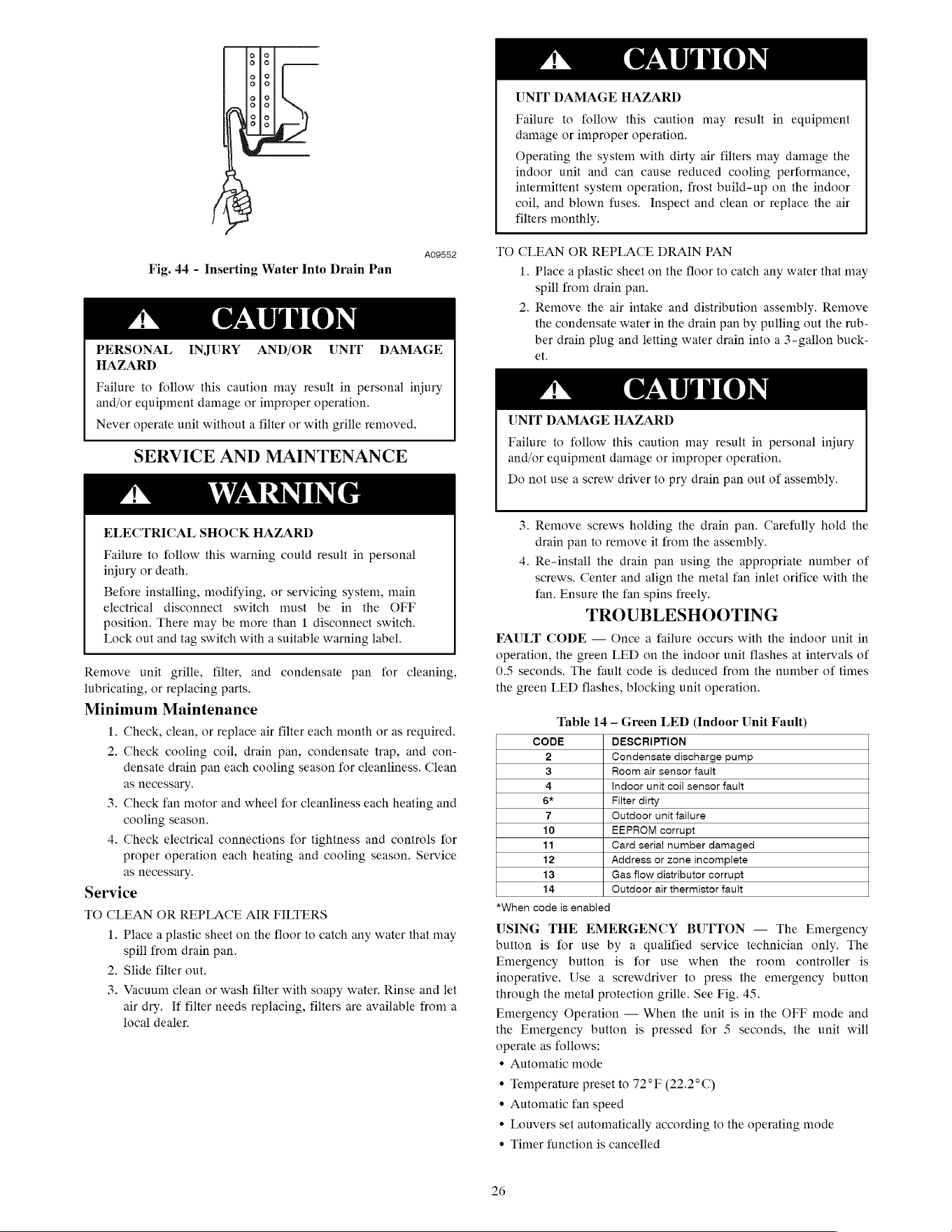
@o
0a
O00
O6
So
o
0
oa
o
So
3
VB
A09552
Fig.
44
-
Inserting
Water
Into
Drain Pan
PERSONAL
HAZARD
INJURY
AND/OR
UNIT
DAMAGE
Failure
to
follow
this
caution
may
result
in
personal
injury
and/or
equipment
damage
or
improper
operation.
Never
operate
unit
without
a
filter
or
with
grille
removed.
SERVICE
AND
MAINTENANCE
ELECTRICAL
SHOCK
HAZARD
Failure
to
follow
this
warning
could
result
in
personal
injury
or
death.
Before
installing,
modifying,
or
servicing
system,
main
electrical
disconnect
switch
must
be
in
the
OFF
position.
There
may
be
more
than
1
disconnect
switch.
Lock
out
and
tag
switch
with
a
suitable
warning
label.
Remove
unit
grille,
filter,
and
condensate
pan
for
cleaning,
lubricating,
or
replacing
parts.
Minimum
Maintenance
1.
Check,
clean,
or
replace
air
filter
each
month
or
as
required.
2.
Check
cooling
coil,
drain
pan,
condensate
trap,
and
con-
densate
drain
pan each
cooling
season
for
cleanliness.
Clean
as
necessary.
3.
Check
fan
motor
and
wheel
for
cleanliness
each
heating
and
cooling
season.
4,
Check
electrical
connections
for
tightness
and
controls
for
proper
operation
each
heating
and
cooling
season.
Service
as
necessary.
Service
TO
CLEAN
OR
REPLACE
AIR
FILTERS
1.
Place
a
plastic
sheet
on
the
floor
to
catch any
water
that
may
spill
from
drain
pan.
.
Slide
filter
out.
.
Vacuum
clean
or
wash
filter
with
soapy
water.
Rinse
and
let
air
dry.
If
filter
needs
replacing,
filters are
available
from
a
local
dealer.
Ww
be
UNIT
DAMAGE
HAZARD
Failure
to
follow
this
caution
may
result
in
equipment
damage
or
improper
operation.
Operating
the
system
with
dirty
air
filters
may
damage
the
indoor
unit
and
can
cause
reduced
cooling
performance,
intermittent
system
operation,
frost
build-up
on
the
indoor
coil,
and
blown
fuses.
Inspect
and
clean
or
replace
the
air
filters
monthly.
TO
CLEAN
OR
REPLACE
DRAIN
PAN
1.
Place
a
plastic
sheet
on
the
floor
to
catch any
water
that
may
spill
from
drain
pan.
2.
Remove
the
air
intake
and
distribution
assembly.
Remove
the
condensate
water
in
the
drain
pan
by
pulling
out
the
rub-
ber
drain
plug
and
letting
water
drain
into
a
3-gallon
buck-
et.
UNIT
DAMAGE
HAZARD
Failure
to
follow
this
caution
may
result
in
personal
injury
and/or
equipment
damage
or
improper
operation.
Do
not
use
a
screw
driver
to
pry
drain
pan
out
of
assembly.
3.
Remove
screws
holding
the
drain
pan.
Carefully
hold
the
drain
pan
to
remove
it
from
the
assembly.
4.
Re-install
the
drain
pan
using
the
appropriate
number
of
screws.
Center
and
align
the
metal
fan
inlet
orifice
with
the
fan.
Ensure
the
fan
spins
freely.
TROUBLESHOOTING
FAULT
CODE
—
Once
a
failure
occurs
with
the
indoor
unit
in
operation,
the
green
LED
on
the
indoor
unit
flashes
at
intervals
of
0.5
seconds.
The
fault
code
is
deduced
from
the
number
of
times
the
green
LED
flashes,
blocking
unit
operation.
Table
14
—
Green
LED
(Indoor
Unit
Fault)
CODE
DESCRIPTION
2
Condensate
discharge
pump
3
Room
air
sensor
fault
4
Indoor
unit
coil
sensor
fault
6*
Filter
dirty
7
Outdoor
unit
failure
10
EEPROM
corrupt
11
Card
serial
number
damaged
12
Address
or
zone
incomplete
13
Gas
flow
distributor
corrupt
14
Outdoor
air
thermistor
fault
*When
code
is
enabled
USING
THE
EMERGENCY
BUTTON
—
The
Emergency
button
is
for
use
by
a
qualified
service
technician
only.
The
Emergency
button
is
for
use
when
the
room
controller
is
inoperative.
Use
a
screwdriver
to
press
the
emergency
button
through
the
metal
protection
grille.
See
Fig.
45.
Emergency
Operation
—
When
the
unit
is
in
the
OFF
mode
and
the
Emergency
button
is
pressed
for
5
seconds,
the
unit will
operate
as
follows:
¢
Automatic
mode
¢
Temperature
preset
to
72°F
(22.2°C)
¢
Automatic
fan
speed
¢
Louvers
set
automatically
according
to
the
operating
mode
¢
Timer
function
is
cancelled
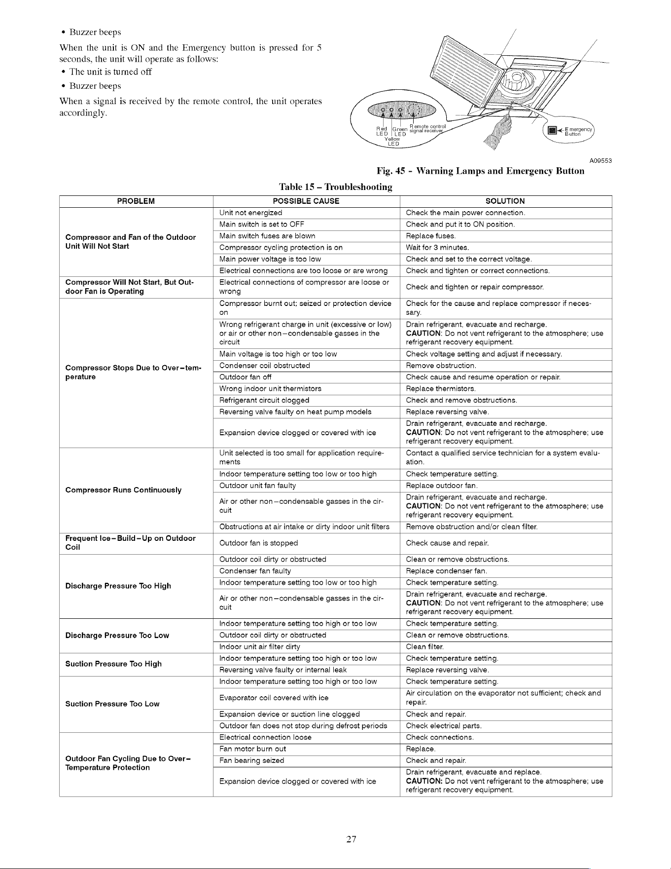
¢
Buzzer
beeps
When
the
unit
is
ON
and
the
Emergency
button
is
pressed
for
5
seconds,
the
unit will
operate
as
follows:
¢
The
unit
is
turned
off
¢
Buzzer
beeps
When
a
signal
is
received
by
the
remote
control,
the
unit
operates
accordingly.
A09553
Fig.
45
-
Warning
Lamps
and
Emergency
Button
Table
15
—
Troubleshooting
PROBLEM
POSSIBLE
CAUSE
SOLUTION
Compressor
and
Fan
of
the
Outdoor
Unit
Will
Not
Start
Unit not
energized
Check
the
main
power
connection.
Main
switch
is
set
to
OFF
Check
and
put
it
to
ON
position.
Main
switch
fuses
are
blown
Replace
fuses.
Compressor
cycling
protection
is
on
Wait
for
3
minutes.
Main
power
voltage
is
too
low
Check
and
set
to
the
correct
voltage.
Electrical
connections
are
too
loose
or
are
wrong
Check
and
tighten
or
correct
connections.
Compressor
Will
Not
Start,
But
Out-
door
Fan
is
Operating
Electrical
connections
of
compressor
are
loose
or
wrong
Check
and
tighten
or
repair
compressor.
Compressor
Stops Due
to
Over—tem-
perature
Compressor
burnt
out;
seized
or
protection
device
on
Check
for
the
cause
and replace
compressor
if
neces-
sary.
Wrong
refrigerant
charge
in
unit
(excessive
or
low)
or
air
or
other
non—condensable
gasses
in
the
circuit
Drain
refrigerant,
evacuate
and
recharge.
CAUTION:
Do
not
vent refrigerant
to
the
atmosphere;
use
refrigerant
recovery
equipment.
Main
voltage
is
too
high
or
too
low
Check
voltage
setting
and
adjust
if
necessary.
Condenser
coil
obstructed
Remove
obstruction.
Outdoor
fan
off
Check
cause
and
resume
operation
or
repair.
Wrong
indoor
unit
thermistors
Replace
thermistors.
Refrigerant
circuit
clogged
Check
and
remove
obstructions.
Reversing
valve
faulty
on
heat
pump
models
Replace
reversing
valve.
Expansion
device
clogged
or
covered
with
ice
Drain
refrigerant,
evacuate
and
recharge.
CAUTION:
Do
not
vent refrigerant
to
the
atmosphere;
use
refrigerant
recovery
equipment.
Compressor
Runs
Continuously
Unit
selected
is
too
small
for
application
require-
ments
Contact
a
qualified
service
technician
for
a
system
evalu-
ation.
Indoor
temperature
setting
too
low
or
too
high
Check
temperature
setting.
Outdoor
unit
fan
faulty
Replace
outdoor
fan.
Air
or
other
non—condensable
gasses
in
the
cir-
cuit
Drain
refrigerant,
evacuate
and
recharge.
CAUTION:
Do
not
vent refrigerant
to
the
atmosphere;
use
refrigerant
recovery
equipment.
Obstructions
at
air
intake
or
dirty
indoor
unit
filters
Remove
obstruction
and/or
clean
filter.
Frequent
Ice-—Build-—Up
on
Outdoor
Coil
Outdoor
fan
is
stopped
Check
cause
and
repair.
Discharge
Pressure
Too
High
Outdoor
coil
dirty
or
obstructed
Clean
or
remove
obstructions.
Condenser
fan
faulty
Replace
condenser
fan.
Indoor
temperature
setting
too
low
or
too
high
Check
temperature
setting.
Air
or
other
non—condensable
gasses
in
the
cir-
cuit
Drain
refrigerant,
evacuate
and
recharge.
CAUTION:
Do
not
vent refrigerant
to
the
atmosphere;
use
refrigerant
recovery
equipment.
Discharge
Pressure
Too
Low
Indoor
temperature
setting
too
high
or
too
low
Check
temperature
setting.
Outdoor
coil
dirty
or
obstructed
Clean
or
remove
obstructions.
Indoor
unit
air
filter
dirty
Clean
filter.
Suction
Pressure
Too
High
Indoor
temperature
setting
too
high
or
too
low
Check
temperature
setting.
Reversing
valve
faulty
or
internal
leak
Replace
reversing
valve.
Suction
Pressure
Too
Low
Indoor
temperature
setting
too
high
or
too
low
Check
temperature
setting.
Evaporator
coil
covered
with
ice
Air
circulation
on
the
evaporator
not sufficient;
check
and
repair.
Expansion
device
or
suction
line
clogged
Check
and
repair.
Outdoor
fan
does
not
stop
during
defrost
periods
Check
electrical
parts.
Outdoor
Fan
Cycling
Due
to
Over-
Temperature
Protection
Electrical
connection
loose
Check
connections.
Fan
motor
burn
out
Replace.
Fan
bearing
seized
Check
and
repair.
Expansion
device
clogged
or
covered
with
ice
Drain
refrigerant,
evacuate
and
replace.
CAUTION:
Do
not
vent refrigerant
to
the
atmosphere;
use
refrigerant
recovery
equipment.
Copyright
2010
Carrier
Corp.
*
7310
W.
Morris
St.
*
Indianapolis,
IN
46234
Printed
in
U.S.A.
Edition
Date:
12/10
Catalog
No:
40KMC-Q-3Sl
Manufacturer
reserves
the
right
to
change,
at
any
time,
specifications
and
designs
without
notice
and
without
obligations.
Replaces:
40KMC-—Q-2S8]
28