Loading ...
Loading ...
Loading ...
3
1886
Ceiling Bracket Top housing Hanging Fan Wiring Canopy Blades Light Glass/Bulbs
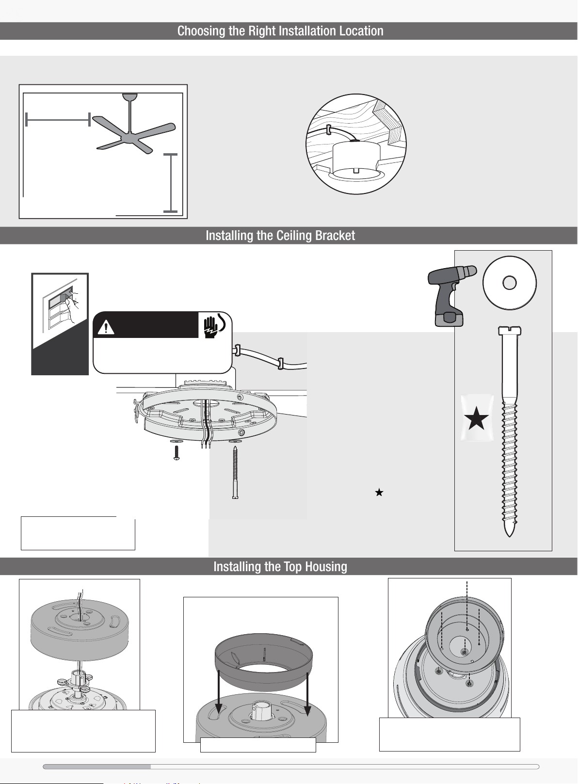
Choosing the Right Installation Location
You probably bought this fan with a location in mind. Let’s check below to make sure it is a good t.
Check the room dimensions: Check the outlet box:
You must be able to
secure the fan to building
structure or fan-rated
outlet box.
30 inches
from blade tip to
nearest wall or
obstruction
7 feet
from bottom edge
of blade to the
oor
Installing the Ceiling Bracket
Use wood screws and
washers (included) when
securing to support structure
with approved electrical
outlet box. Drill 9/64” pilot
holes in support structure
to aid in securing ceiling
bracket with hardware found
in the hardware bag.
Use machine screws
(provided with outlet box)
and washers when securing
to existing ceiling fan-rated
outlet box. Make sure it is
securely installed and is
acceptable for fan support of
31.8 kg (70 lbs) or less.
Option 2:
Wood Screws
Option 1:
Machine Screws
OFF
Turn Power
Do this rst!
The machine screws are the ones
that came with your outlet box.
Hunter Pro Tip:
BAG
Wood Screw
Washer
x2
x2
You have two options for installation. Pick which one works best for your location. Remove any existing
bracket prior to installation. Only use the provided Hunter ceiling bracket that came in your fan’s box.
Installing the Top Housing
Thread the wires through the top housing.
Place the top housing onto the motor housing
so that the holes in the top housing lineup with
the holes in the motor housing and the adapter.
Rest the trim ring on the top housing.
Place the canopy on the top housing. Ensure
all four screw holes line up with the screw
holes in both the top housing and the adapter.
WARNING
To avoid possible electrical shock, before
installing your fan, disconnect the power by
turning off the circuit breakers to the outlet
box associated with the wall switch location.
Loading ...
Loading ...
Loading ...