Loading ...
Loading ...
Loading ...
PLEASE READ AND SAVE THESE
IMPORTANT SAFETY INSTRUCTIONS
When using electrical appliances, basic safety precautions
should always be taken including the following:
1. Read all instructions before using this appliance.
2. Use fan only for purposes described in the instruction
manual.
3. This fan is not intended for continuous operation or
equivalent.
4. To protect against electrical shock do not immerse unit,
plug or cord in water or spray with liquids and plug
the appliance directly into a 120V AC electrical outlet.
5. Close supervision is necessary when any appliance is
used by or near children.
6. Unplug from outlet when not in use, when moving
fan from one location to another, before putting on or
taking off parts and before cleaning.
7. Avoid contact with moving parts.
8. Do not operate in the presence of explosive and/or
flammable fumes.
9. To avoid fire hazard, never place the cord under rugs
or any parts near an open flame, cooking or other
heating appliance.
10. Do not operate any appliance with a damaged cord
or plug, after the appliance malfunctions, or has been
dropped/damaged in any manner. Discard fan or
contact customer service.
11 . Do not run cord under carpeting. Do not cover cord
with throw rugs, runner, or similar coverings. Do not
route cord under furniture or appliances. Arrange cord
away from traffic area and where it will not be tripped
over.
12. The use of attachments not recommended or sold by
the appliance manufacturer may cause hazards.
13. Do not let the cord hang over the edge of a table,
counter or come in contact with hot surfaces or leave
exposed to high traffic areas.
14. Do not use outdoors.
15. To disconnect, grip plug and pull from wall outlet.
Never yank on cord.
16. Always use on a dry, level surface.
17. Do not operate fan until fully assembled with all parts
properly in place.
18. This product is intended for household use only and
not for commercial or industrial applications.
19. WARNING: To reduce the risk of fire or electric
shock, do not use this fan with any solid-state speed
control device.
20. For models with overload protection (fuse). A blown
fuse indicates an overload or short-circuit situation.
If the fuse blows, unplug the product from the outlet.
Replace the fuse as per the user servicing instructions
(follow product marking for proper fuse rating) and
check the product. If the replacement fuse blows, a
short circuit may be present and the product should
be discarded or contact customer service.
ASSEMBLY INSTRUCTIONS (SEE FIGURE 1)
NOTE: MAKE SURE YOU REMOVE ALL CONTENTS OF THE
PACKAGE. PLEASE CHECK PACKAGING MATERIALS FOR
PARTS THAT COULD BE REQUIRED TO OPERATE YOUR FAN.
Estimated assembly time: 5–10 minutes
1. Remove T-shaped screw and washer from the outer
pole (O). Insert the lower end of the outer pole
through the hole in the center of base (P) and twist
clockwise into position.
2. Turn the base upside down (pole facing the floor) and
place the base weight (Q) into the base.
3. Insert the threaded end of the T-shaped locking
lever (S) into the hole of the washer (R), weight and
through the base.
4. Turn the T-shaped locking lever clockwise to securely
attach the pole to the base.
Figure 1
THIS APPLIANCE HAS A POLARIZED PLUG (one blade is wider than
the other). To reduce the risk of electric shock, this plug is intended to
fit in a polarized outlet only one way. If the plug does not fit fully in
the outlet, reverse the plug. If it still does not fit, contact a qualified
electrician to install the proper outlet.
DO NOT ATTEMPT TO MODIFY THIS PLUG OR DEFEAT THIS
SAFETY FEATURE IN ANY WAY.
PLEASE READ AND SAVE
THESE IMPORTANT SAFETY
INSTRUCTIONS
PARTS AND ASSEMBLY FEATURES - OPERATIONS
C
I
A . Logo Plate
B. Front Grill
C. Blade Cap
D . Fan Blade
E. Rear Grill Mounting Nut
F . Rear Grill
G . Grill Lock
H . Motor Shaft
I . Oscillation Knob
J . Motor Housing
K . Speed Control Knob
L . Fan Post Screw
M. Extension Pole
N . Height Adjustment Collar
O . Outer Pole
P . Base
Q . Base Weight
R . Washer
S . T-shaped Locking Lever
T . Grill Clips
B
D
E
F
H
J
A
G
T
L
K
N
M
O
P
Q
R
S
5. Set the base on the floor, weight side down.
6. Loosen fan post screw (L) and slide motor housing (J)
over top of extension pole. Tighten fan post screw.
7. Line up the 2 holes of the rear grill with the posts on
the motor housing assembly.
8. Secure rear grill to motor housing assembly with rear
grill mounting nut. Turn clockwise to tighten.
9. Slide blade (D) over motor shaft (H).
10. Secure fan blade to motor shaft with the blade cap
(C). Turn counter-clockwise to tighten.
11. Open the expandable grill clips (T) located around the
perimeter of the front grill (B).
12. Use the pre-assembled grill lock (G) to align the hole
located at the bottom of the rear grill (F). Slide the
hanging clip on top of the front grill over the top of
the rear grill.
13. Fully secure grill lock into the hole by applying
pressure until it snaps into place.
14. Close expandable clips over the rear grill.
TILT ADJUSTMENT
To change the tilting angle of the fan head, simply move
the fan head manually position the fan head to the
desired angle. An audible click will confirm each angle
adjustment.
HEIGHT ADJUSTMENT
1. Turn the height adjustment collar (N) counterclockwise
to loosen pole.
2. Adjust the extension pole (M) to the desired height,
and firmly tighten the height adjustment collar in
a clockwise direction.
USER SERVICING INSTRUCTIONS
Follow these instructions to safely and correctly care for
your fan.
REPLACEABLE FUSE
If your (5 Amp, 125 Volt) replaceable fuse blows,
please visit our website at www.getholmesfans.com for
information on how to order a new fuse.
REPLACING THE FUSE
1. Unplug your fan.
Grasp plug and remove
from the receptacle or
other outlet device.
NOTE: Do not unplug by
pulling on cord.
2. Open fuse cover, located
on the top of the plug,
by using your thumb or a
flathead screwdriver to slide the cover towards the
prongs.
NOTE: Ensure the fuse cover is completely open
before attempting to remove fuse.
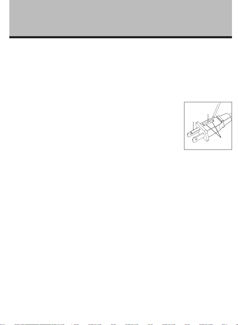
3. Remove fuse carefully by using a small screwdriver to
pry it from the compartment at the metal ends of the
fuse. (See Figure 2)
4. Place plug on a solid, flat surface. Insert new 5 Amp,
125 Volt fuse into fuse compartment. Use a small
screwdriver to secure the metal ends of the fuse into
the compartment.
CAUTION: Risk of fire. Replace fuse only with 5
Amp, 125 Volt fuse.
5. Slide fuse cover closed completely.
NOTE: If fuse cover is difficult to close, make sure
the fuse is completely secured in place by pressing on
metal ends of the fuse.
CAUTION: Risk of fire. Do not replace the
attachment plug. It contains a safety device (fuse)
that should not be removed. Discard product if the
attachment plug is damaged.
OPERATING INSTRUCTIONS
1. Set fan base on a dry, level, stable surface.
2. Plug cord into any standard 120 volt AC outlet.
3. Adjust the power ON/OFF and speed with the speed
control knob (K).
O-OFF
3-High
2-Medium
1-Low
4. To start oscillation, press the oscillation knob (I). To
stop oscillation, pull oscillation knob up.
Figure 2
Fuse
Fuse cover
Metal ends
Loading ...
Loading ...