
MultiSync V323-3
Please find your model name in the label on the rear side of monitor.
Large Format Display
User’s Manual
MODEL: V323-3

Index
Registration Information ............................................................................................................................... English-1
Important Information ................................................................................................................................... English-2
WARNING ....................................................................................................................................... English-2
CAUTION ........................................................................................................................................ English-2
Safety Precautions, Maintenance & Recommended Use............................................................................. English-3
Safety Precautions and Maintenance ............................................................................................. English-3
Recommended Use ........................................................................................................................ English-3
Ergonomics ..................................................................................................................................... English-3
Cleaning the LCD Panel ................................................................................................................. English-3
Cleaning the Cabinet ...................................................................................................................... English-3
Contents ....................................................................................................................................................... English-4
Installation .................................................................................................................................................... English-5
Attaching Mounting Accessories ..................................................................................................... English-6
Parts Name and Functions ........................................................................................................................... English-8
Control Panel .................................................................................................................................. English-8
Terminal Panel ................................................................................................................................ English-9
Wireless Remote Control ................................................................................................................ English-10
Operating Range for the Remote Control ....................................................................................... English-11
Setup ............................................................................................................................................................ English-12
Connections ................................................................................................................................................. English-14
Wiring Diagram ............................................................................................................................... English-14
Connecting a Personal Computer ................................................................................................... English-15
Connecting a DVD Player or Computer with HDMI out .................................................................. English-15
Connecting a Computer with DisplayPort ....................................................................................... English-15
Basic Operation ............................................................................................................................................ English-16
Power ON and OFF Modes ............................................................................................................ English-16
Power Indicator ............................................................................................................................... English-17
Using Power Management ............................................................................................................. English-17
Selecting a video source ................................................................................................................. English-17
Picture Aspect ................................................................................................................................. English-17
Information OSD ............................................................................................................................. English-18
Picture Mode ................................................................................................................................... English-18
OSD (On-Screen-Display) Controls.............................................................................................................. English-19
PICTURE ........................................................................................................................................ English-20
ADJUST .......................................................................................................................................... English-20
AUDIO ............................................................................................................................................ English-21
SCHEDULE .................................................................................................................................... English-21
PIP* ................................................................................................................................................. English-22
OSD ................................................................................................................................................ English-22
MULTI DISPLAY ............................................................................................................................. English-23
DISPLAY PROTECTION ................................................................................................................ English-24
ADVANCED OPTION ..................................................................................................................... English-25
Remote Control Function .............................................................................................................................. English-28
Controlling the LCD monitor via RS-232C Remote Control.......................................................................... English-30
Controlling the LCD monitor via LAN Control ................................................................................................English-32
Connecting to a Network ................................................................................................................ English-32
Network Setting by Using an HTTP Browser .................................................................................. English-32
Features ....................................................................................................................................................... English-37
Troubleshooting ............................................................................................................................................ English-38
Specifications ............................................................................................................................................... English-39
Pin Assignment ............................................................................................................................................. English-40
Manufacturer’s Recycling and Energy Information ....................................................................................... English-41
English-1
English
Registration Information
Cable Information
CAUTION: Use the provided specified cables with this product so as not to interfere with radio and television reception.
For DVI and mini D-Sub 15-pin, please use a shielded signal cable with ferrite core.
For D-Sub 9-Pin, HDMI and DisplayPort, please use a shielded signal cable.
Use of other cables and adapters may cause interference with radio and television reception.
FCC Information
WARNING: The Federal Communications Commission does not allow any modifications or changes to the unit EXCEPT those specified by
NEC Display Solutions of America, Inc. in this manual. Failure to comply with this government regulation could void your right to operate this equipment.
This equipment has been tested and found to comply with the limits for a Class B digital device, pursuant to part 15 of the FCC Rules. These limits are
designed to provide reasonable protection against harmful interference in a residential installation. This equipment generates, uses, and can radiate radio
frequency energy, and, if not installed and used in accordance with the instructions, may cause harmful interference to radio communications. However,
there is no guarantee that interference will not occur in a particular installation. If this equipment does cause harmful interference to radio or television
reception, which can be determined by turning the equipment off and on, the user is encouraged to try to correct the interference by one or more of the
following measures:
•Reorientorrelocatethereceivingantenna.
•Increasetheseparationbetweentheequipmentandreceiver.
•Connecttheequipmentintoanoutletonacircuitdifferentfromthattowhichthereceiverisconnected.
•Consultyourdealeroranexperiencedradio/TVtechnicianforhelp.
Ifnecessary,theusershouldcontactthedealeroranexperiencedradio/televisiontechnicianforadditionalsuggestions.
The user may find the following booklet, prepared by the Federal Communications Commission, helpful: “How to Identify and Resolve Radio-TV
Interference Problems.” This booklet is available from the U.S. Government Printing Office, Washington, D.C., 20402, Stock No. 004-000-00345-4.
SUPPLIER’S DECLARATION OF CONFORMITY
This device complies with Part 15 of FCC Rules. Operation is subject to the following two conditions. (1) This device may not cause harmful interference,
and (2) this device must accept any interference received, including interference that may cause undesired operation.
U.S. Responsible Party: NEC Display Solutions of America, Inc.
Address: 3250 Lacey Rd, Ste 500
Downers Grove, IL 60515
Tel. No.: (630) 467-3000
Type of Product: Display Monitor
Equipment Classification: Class B Peripheral
Model: MultiSync V323-3 (V323-3)
Windows is a registered trademark of Microsoft Corporation.
NEC is a registered trademark of NEC Corporation.
DisplayPort and DisplayPort Compliance Logo are trademarks owned by the Video Electronics Standards Association
in the United States and other countries.
Trademark PJLink is a trademark applied for trademark rights in Japan, the United States of America and other
countries and areas.
The terms HDMI and HDMI High-Definition Multimedia Interface, and the HDMI Logo are trademarks or
registered trademarks of HDMI Licensing Administrator, Inc. in the United States and other countries.
CRESTRON and CRESTRON ROOMVIEW are trademarks or registered trademarks of Crestron Electronics, Inc. in the
United States and other countries.
MultiSync is a trademark or registered trademark of NEC Display Solutions, Ltd. in Japan and other countries.
All other brands and product names are trademarks or registered trademarks of their respective owners.
GPL/LGPL Software Licenses
The product includes software licensed under GNU General Public License (GPL), GNU Lesser General Public License (LGPL), and others.
For more information on each software, see “readme.pdf” inside the “about GPL&LGPL” folder on the supplied CD-ROM.
English-2
Important Information
WARNING
TO PREVENT FIRE OR SHOCK HAZARDS, DO NOT EXPOSE THIS UNIT TO RAIN OR MOISTURE. ALSO, DO NOT
USE THIS UNIT’S POLARIZED PLUG WITH AN EXTENSION CORD RECEPTACLE OR OTHER OUTLETS UNLESS THE
PRONGS CAN BE FULLY INSERTED.
REFRAIN FROM OPENING THE CABINET AS THERE ARE HIGH VOLTAGE COMPONENTS INSIDE. REFER SERVICING
TO QUALIFIED SERVICE PERSONNEL.
CAUTION
TO REDUCE THE RISK OF ELECTRIC SHOCK, MAKE SURE POWER CORD IS UNPLUGGED FROM WALL SOCKET. TO
FULLY DISENGAGE THE POWER TO THE UNIT, PLEASE DISCONNECT THE POWER CORD FROM THE AC OUTLET.
DO NOT REMOVE COVER (OR BACK). NO USER SERVICEABLE PARTS INSIDE. REFER SERVICING TO QUALIFIED
SERVICE PERSONNEL.
This symbol warns user that uninsulated voltage within the unit may have sufficient magnitude to cause electric
shock. Therefore, it is dangerous to make any kind of contact with any part inside this unit.
This symbol alerts the user that important literature concerning the operation and maintenance of this unit has been
included. Therefore, it should be read carefully in order to avoid any problems.
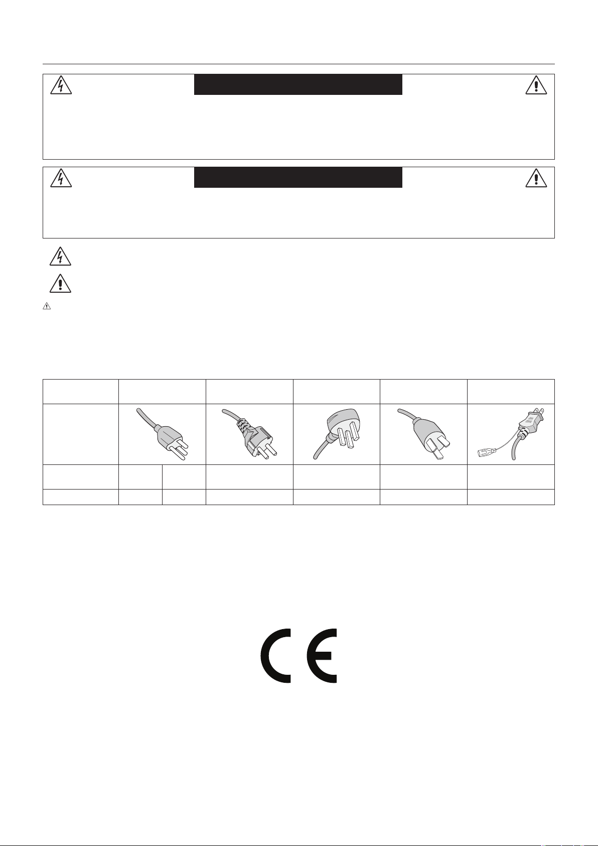
CAUTION: Please use the power cord provided with this device in accordance with the table below. If a power cord is not
supplied with this equipment, please contact NEC. For all other cases, please use the power cord with the plug style that
matches the power socket where the monitor is located. The compatible power cord corresponds to the AC voltage of the power
outlet and has been approved by, and complies with, the safety standards in the country of purchase.
This equipment is designed to be used with a power cord that has a protective earth pin connected to earth. If the power cord is
not connected to the earth, it may cause electric shock. Please make sure the power cord is earthed properly.
Plug Type North America
European
Continental
U.K. Chinese Japanese
Plug Shape
Region
U.S.A./
Canada
Taiwan
EU U.K. China Japan
Voltage
120*
110
230 230 220 100
* When operating this monitor with its AC 125-240V power supply, use a power supply cord that matches the power supply
voltage of the AC power outlet being used.
NOTE: This product can only be serviced in the country where it was purchased.
Use the power cord which has BSMI mark at both ends when you use this monitor in Taiwan.
•TheintendedprimaryuseofthisproductisasanInformationTechnicalEquipmentinanofceordomesticenvironment.
•Theproductisintendedtobeconnectedtoacomputerandisnotintendedforthedisplayoftelevisionbroadcastsignals.

English-3
English
Safety Precautions and Maintenance
FOR OPTIMUM PERFORMANCE, PLEASE NOTE THE
FOLLOWING WHEN SETTING UP AND USING
THE MULTI-FUNCTION MONITOR:
• DO NOT OPEN THE MONITOR. There are no user
serviceable parts inside and opening or removing covers may
exposeyoutodangerousshockhazardsorotherrisks.Refer
all servicing to qualified service personnel.
• Donotspillanyliquidsintothecabinetoruseyourmonitor
near water.
• Donotinsertobjectsofanykindintothecabinetslots,
as they may touch dangerous voltage points, which can
be harmful or fatal or may cause electric shock, fire or
equipment failure.
• Donotplaceanyheavyobjectsonthepowercord.
Damage to the cord may cause shock or fire.
• Donotplacethisproductonaslopingorunstablecart,stand
or table, as the monitor may fall, causing serious damage to
the monitor.
•
Donotmountthisproductupsidedownforanextendedperiod
of time as it may cause permanent damage to the screen.
• Thepowersupplycordyouusemusthavebeenapproved
by and comply with the safety standards of your country.
(Type H05VV-F 3G 1mm
2
should be used in Europe)
• InUK,useaBS-approvedpowercordwithmoldedplug
having a black (5 A) fuse installed for use with this monitor.
• Donotplaceanyobjectsontothemonitoranddonotusethe
monitor outdoors.
• Donotbend,crimporotherwisedamagethepowercord.
• Ifglassisbroken,handlewithcare.
• Donotcoverventonmonitor.
• Donotusemonitorinhightemperature,humid,dusty,oroily
areas.
• Ifmonitororglassisbroken,donotcomeincontactwiththe
liquid crystal and handle with care.
• Allowadequateventilationaroundthemonitor,sothatheat
can properly dissipate. Do not block ventilated openings or
place the monitor near a radiator or other heat sources.
Do not put anything on top of the monitor.
•Thepowercableconnectoristheprimarymeansofdetaching
the system from the power supply. The monitor should be
installed close to a power outlet, which is easily accessible.
• Handlewithcarewhentransporting.Savepackagingfor
transporting.
• Ifusingthecoolingfancontinuously,itisrecommendedto
wipe holes clean a minimum of once a month.
• Pleasecleantheholesofbackcabinettorejectdirtanddust
at least once a year because of set reliability.
• WhenusingaLANcable,donotconnecttoaperipheral
devicewithwiringthatmighthaveexcessivevoltage.
• Donotusemonitorunderrapidtemperatureandhumidity
change condition or avoid cold air from air-conditioning outlet
directly, as it may shorten the lifetime of the monitor or cause
condensation. If condensation happens, let the monitor stand
unplugged until there is no condensation.
Connecting to a TV*
• Cabledistributionsystemshouldbegrounded(earthed)in
accordancewithANSI/NFPA70,theNationalElectricalCode
(NEC), in particular Section 820.93, Grounding of Outer
ConductiveShieldofaCoaxialCable.
• Thescreenofthecoaxialcableisintendedtobeconnected
to earth in the building installation.
Immediately unplug your monitor from the wall outlet and refer
servicing to qualified service personnel under the following
conditions:
• Whenthepowersupplycordorplugisdamaged.
•
If liquid has been spilled, or objects have fallen into the monitor.
• Ifthemonitorhasbeenexposedtorainorwater.
• Ifthemonitorhasbeendroppedorthecabinetdamaged.
• Ifyounoticeanystructuraldamagesuchascracksor
unnatural wobbling.
• Ifthemonitordoesnotoperatenormallybyfollowing
operating instructions.
Recommended Use
• Foroptimumperformance,allow20minutesforwarm-up.
• Restyoureyesperiodicallybyfocusingonanobjectatleast
5 feet away. Blink often.
• Positionthemonitorata90°angletowindowsandotherlight
sourcestominimizeglareandreections.
• CleantheLCDmonitorsurfacewithalint-free,non-abrasive
cloth. Avoid using any cleaning solution or glass cleaner!
• Adjustthemonitor’sbrightness,contrastandsharpness
controls to enhance readability.
• Avoiddisplayingxedpatternsonthemonitorforlong
periods of time to avoid image persistence (after image
effects).
• Getregulareyecheckups.
Ergonomics
Torealizethemaximumergonomicbenets,werecommendthe
following:
• UsethepresetSizeandPositioncontrolswithstandard
signals.
• UsethepresetColorSetting.
• Usenon-interlacedsignals.
• Donotuseprimarycolorblueonadarkbackground,as
it is difficult to see and may produce eye fatigue due to
insufficient contrast.
• Suitable for entertainment purposes at controlled luminous
environments,toavoiddisturbingreectionsfromthescreen.
Cleaning the LCD Panel
• Whentheliquidcrystalpanelisdusty,pleasegentlywipe
with a soft cloth.
• PleasedonotrubtheLCDpanelwithhardmaterial.
• PleasedonotapplypressuretotheLCDsurface.
• PleasedonotuseOAcleanerasitwillcausedeteriorationor
discolor on the LCD surface.
Cleaning the Cabinet
• Unplugthepowersupply
• Gentlywipethecabinetwithasoftcloth
• Tocleanthecabinet,dampentheclothwithaneutral
detergent and water, wipe the cabinet and follow with a dry
cloth.
NOTE:DONOTcleanwithbenzenethinner,alkalinedetergent,
alcoholicsystemdetergent,glasscleaner,wax,polish
cleaner, soap powder, or insecticide. Rubber or vinyl
shouldnotbeincontactwiththecabinetforanextended
periodoftime.Thesetypesofuidsandmaterialscan
cause the paint to deteriorate, crack or peel.
Safety Precautions, Maintenance & Recommended Use
* The product you purchased may not have this feature.
English-4
Contents
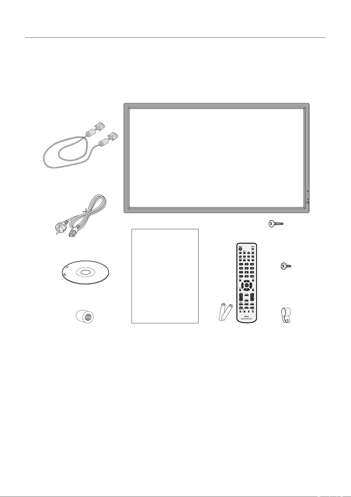
YournewMultiSyncmonitorbox*shouldcontainthefollowing:
•LCDmonitor
•Powercord*
1
•VideoSignalCable
•WirelessRemoteControlandAABatteries*
2
•SetupManual
•CD-ROM
•Clampx1
•Screwwithwasher(M4x10)x1
•WallMountadapterx4
•WallMountadapterscrewx4
Power Cord*
1
Setup Manual
CD-ROM
Video Signal Cable
(DVI-D to DVI-D cable)
Wireless Remote Control
and AA Batteries
Setup Manual
Screw with washer
(M4x10)x1
Clampx1Wallmountadapterx4
Wall mount adapter
screwx4
*Remembertosaveyouroriginalboxandpackingmaterialtotransportorshipthemonitor.
*
1
Type and number of power cords included will depend on the country where the LCD monitor is to be shipped. When more
than one power cord is included, please use the power cord with the plug style that matches the power socket where the
monitor is located. The compatible power cord corresponds to the AC voltage of the power outlet and has been approved by,
and complies with, the safety standards in the country of purchase.
*
2
DependingonthecountrywheretheLCDmonitorisshippedto,AAbatteriesarenotincludedintheboxcontents.
English-5
English
This device cannot be used or installed without the Tabletop
Stand or other mounting accessory for support. For proper
installation it is strongly recommended to use a trained,
NEC authorized service person. Failure to follow NEC
standard mounting procedures could result in damage to the
equipment or injury to the user or installer. Product warranty
does not cover damage caused by improper installation.
Failure to follow these recommendations could result in
voiding the warranty.
Mounting
DO NOT mount the monitor yourself. Please ask dealer.
For proper installation it is strongly recommended to use
a trained, qualified technician. Please inspect the location
where the unit is to be mounted. Mounting on wall or ceiling
is the customer’s responsibility. Not all walls or ceilings are
capable of supporting the weight of the unit. Product warranty
does not cover damage caused by improper installation,
remodelling, or natural disasters. Failure to comply with these
recommendations could result in voiding the warranty.
DO NOT block ventilated openings with mounting
accessories or other accessories.
For NEC Qualified Personnel:
To ensure safe installation, use two or more brackets to
mount the unit. Mount the unit to at least two points on the
installation location.
Please note the following when mounting
on wall or ceiling
•Whenusingmountingaccessoriesotherthanthosethat
are NEC approved, they must comply with the VESA-
compatible (FDMlv1) mounting method.
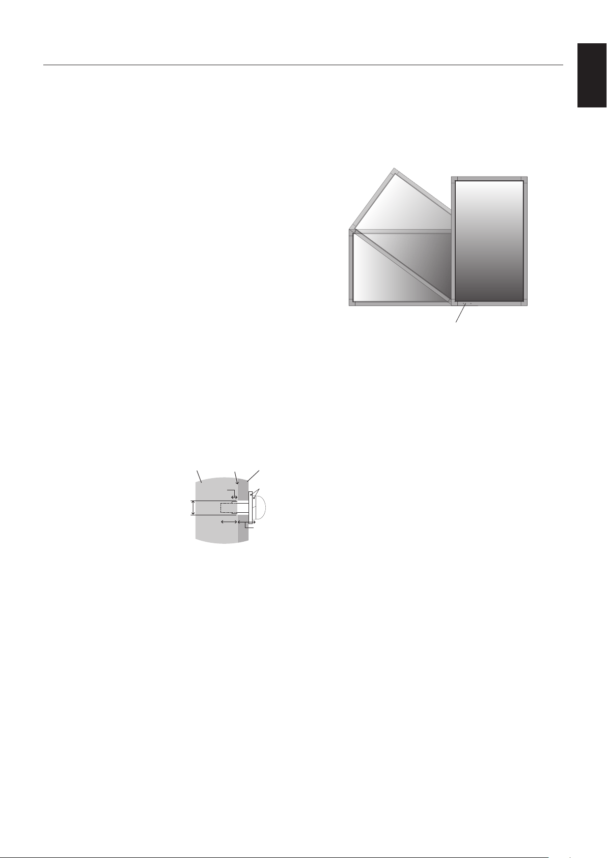
•NECstronglyrecommends
usingsizeM6screws
(10-12 mm + thickness
of bracket and washers in
length). If using screws
longer than 10-12 mm,
check the depth of the hole.
(Recommended Fasten
Force:470-635N•cm).
Bracket hole should be under 8.5 mm.
NEC recommends mounting interfaces that comply
with UL1678 standard in North America.
•Priortomounting,inspecttheinstallationlocationto
insure that it is strong enough to support the weight of the
unit so that the unit will be safe from harm.
•Refertotheinstructionsincludedwiththemounting
equipment for detailed information.
•Makesurethereisnogapbetweenthemonitorandthe
bracket.
•When used in a video wall configuration for a longer
time,slightexpansionofthedisplaysmayhappendueto
temperature changes. Due to this it is recommended that
over one millimeter gap is kept between adjacent display
edges.
Installation
Orientation
•Whenusingthedisplayintheportraitposition,the
monitor should be rotated clockwise so that the left side
is moved to the top, right side is moved to the bottom.
Thiswillallowforproperventilationandwillextendthe
lifetime of the monitor. Improper ventilation may shorten
the lifetime of the monitor.
LED Indicator
Mounting location
•Theceilingandwallmustbestrongenoughtosupportthe
monitor and mounting accessories.
•DONOTinstallinlocationswhereadoororgatecanhit
the unit.
•DONOTinstallinareaswheretheunitwillbesubjected
to strong vibrations and dust.
•DONOTinstallnearwherethemainpowersupplyenters
the building.
•Donotinstallinwherepeoplecaneasilygrabandhang
onto the unit or the mounting apparatus.
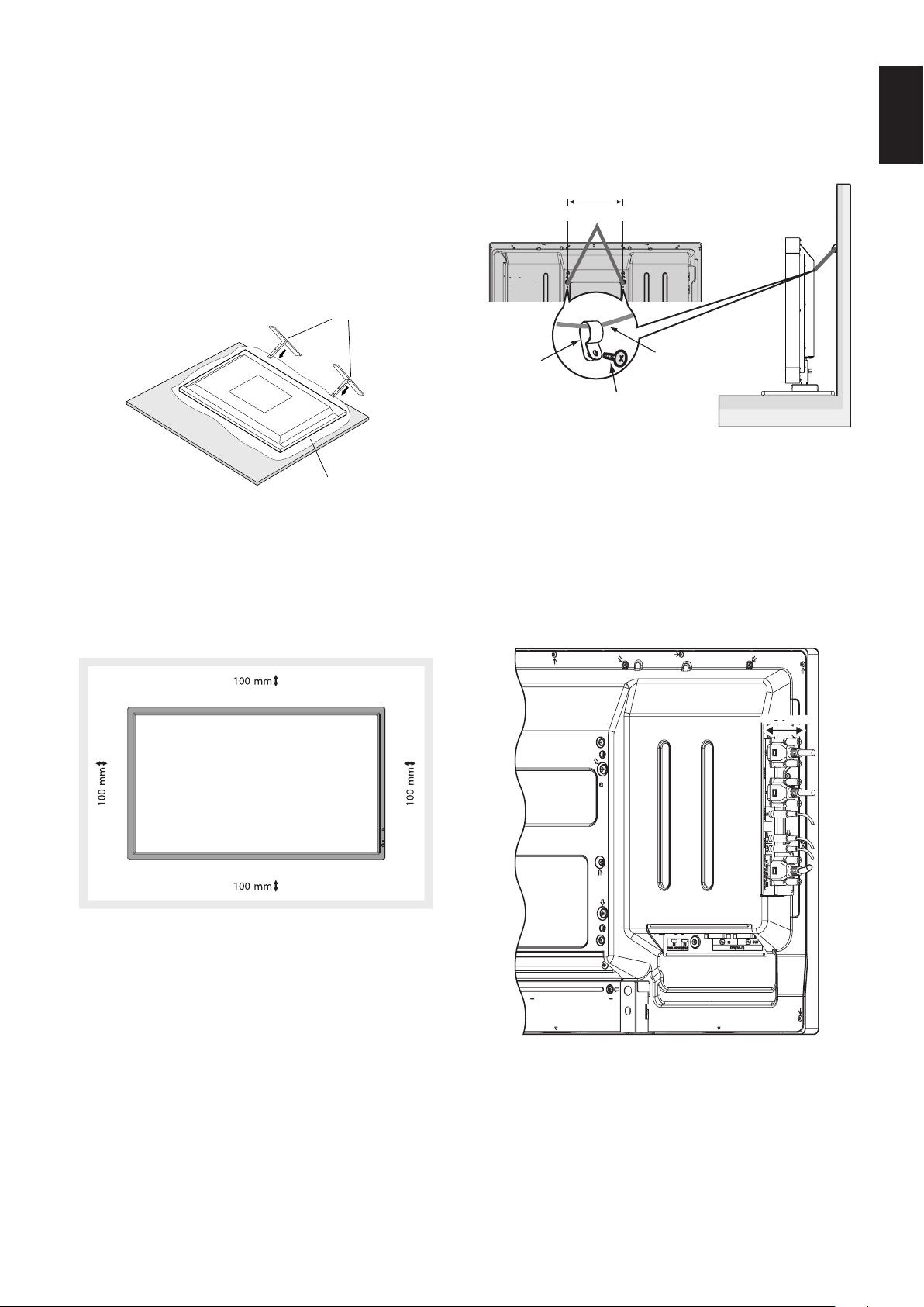
•Whenmountinginarecessedarea,asinawall,leaveat
least 4 inches (100 mm) of space between the monitor
and the wall for proper ventilation.
•Allowadequateventilationorprovideairconditioning
around the monitor, so that heat can properly dissipate
away from the unit and mounting apparatus.
Mounting on ceiling
•Ensurethattheceilingissturdyenoughtosupportthe
weight of the unit and the mounting apparatus over time,
againstearthquakes,unexpectedvibrations,andother
externalforces.
•Besuretheunitismountedtoasolidstructurewithin
the ceiling, such as a support beam. Secure the monitor
using bolts, spring lock washers, washer and nut.
•DONOTmounttoareasthathavenosupportinginternal
structure. DO NOT use wood screws or anchor screws for
mounting. DO NOT mount the unit to trim or to hanging
xtures.
Maintenance
•Periodicallycheckforloosescrews,gaps,distortions,
or other problems that may occur with the mounting
apparatus. If a problem is detected, please refer to
qualified personnel for service.
•Regularlycheckthemountinglocationforsignsof
damage or weakness that may occur over time.
Screw
Unit
10-12 mm
Thickness
of bracket
and washers
under
8.5 mm
No gap
Washers
Mounting
Bracket
No thread
4 mm
English-6
Attaching Mounting Accessories
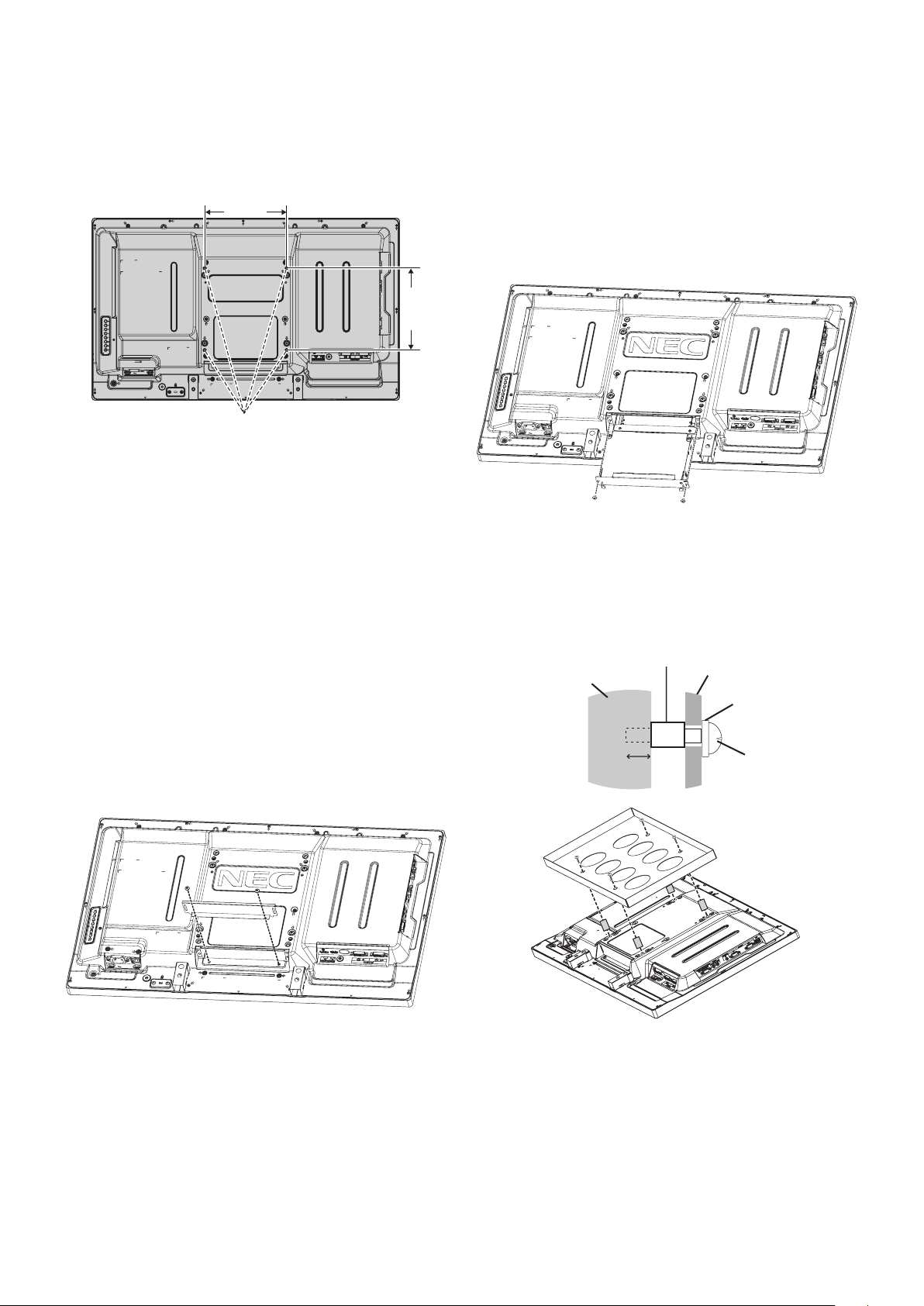
The monitor is designed for use with the VESA mounting
system.
1. Attach Mounting Accessories
Be careful to avoid tipping monitor when attaching
accessories.
VESA Mounting Interface
200 mm
200 mm
Mounting accessories can be attached with the monitor in
the face down position. To avoid damaging the screen face,
place the protective sheet on the table underneath the LCD.
The protective sheet was wrapped around the LCD in the
original packaging. Make sure there is nothing on the table
that can damage the monitor.
When using mounting accessories other than NEC compliant
and approved, they must comply with the VESA-compatible
mounting method.
NOTE: Prior to installation, be sure to place the monitor
onaatareawithadequatespace.
2. Using Option Board
1. Turn off the main power switch.
2. Place the monitor face down on the protective sheet.
NOTE:Besuretoplacethemonitoronaatandadequate
space.
3. Remove the attached slot cover by unscrewing the
installed screws (Figure 1).
Figure 1
4. Insert the option board into the monitor andx it with the
removed screws (Figure 2).
NOTE: Please contact your supplier for available option
boards.
Donotapplyexcessiveforcetomanipulatethe
optionalboardbeforexingitwithscrews.
Make sure that the board is inserted into the slot in
the correct orientation.
CAUTION: Ensure the option board is attached by the
removed screws. As falling the option board may
exposeyoutodanger.
Figure 2
3. Using Wall Mount Adapter
If the mounting accessory interferes with ventilation hole, use
the included wall mount adaptors and screws. If the adaptor
screws are too long, include a washer to reduce the depth.
Washer not included.
Wall mount
adapter screw
Washer
Mounting bracket
Unit
Wall mount adapter
10-12 mm
Pictured mounting solutions may not be available in some
countries.
English-7
English
4. Installing and removing optional table
top stand
CAUTION: Installing and removing the stand must be done
by two or more people.
To install, follow those instructions included with the stand or
mounting apparatus. Use only those devices recommended
by the manufacturer.
NOTE: Use ONLY the thumbscrews which are included
with the optional table top stand.
When installing the LCD monitor stand, handle the unit with
care to avoid pinching your fingers.
Optional table top stand
Table
Protective Sheet
NOTE: Install the stand in the direction of the arrow which
is imprinted on the surface of the stand. Use the
ST-322 for V323-3.
5. Ventilation Requirements
When mounting in an enclosed space or recessed area,
leave adequate room between the monitor and the enclosure
to allow heat to disperse, as shown below.
Allow adequate ventilation or provide air conditioning around
the monitor, so that heat can properly dissipate away from
the unit and mounting apparatus; especially when you use
monitors in multiple screen.
NOTE: The sound quality of the internal speakers will
differ according to the acoustics of the room.
6. Prevent Tipping
When using the display with the optional table top stand
fasten the LCD to a wall using a cord or chain that can
support the weight of the monitor in order to prevent the
monitor from falling. Fasten the cord or chain to the monitor
using the provided clamps and screws.
Screw (M4)*
Cord or chain
Clamp*
196 mm
Screw Holes
*: included in option stand.
Before attaching the LCD monitor to the wall, make sure that
the wall can support the weight of the monitor.
Be sure to remove the cord or chain from the wall before
moving the LCD.
7. Using Side Terminal
It has very narrow width between the terminal and the
monitor side edge.
When setting cables within the monitor area, use appropriate
cable and manage it within the width.
48.7 mm
English-8
Parts Name and Functions
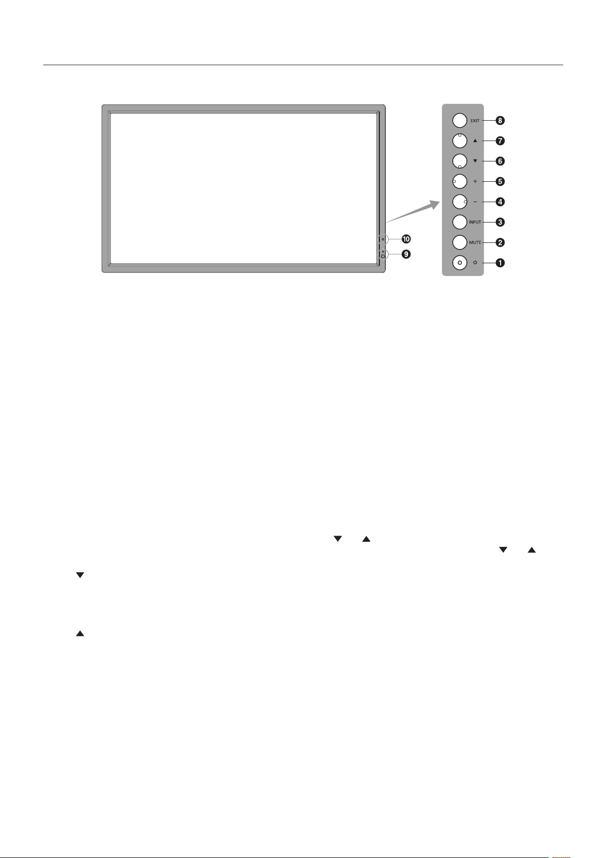
Control Panel
A POWER button
Switchesthepoweron/off.Seealsopage16.
B MUTE button
SwitchestheaudiomuteON/OFF.
C INPUT button
Acts as SET button within OSD menu. (Toggle switches
between[DVI],[DPORT],[VGA],[HDMI],[DVD/HD],
[SCART], [VIDEO] or [S-VIDEO]). These are available input
only, shown as their factory preset name.
D MINUS button
Acts as (-) button to decrease the adjustment with OSD menu.
Decreases the audio output level when the OSD menu is
turned off.
E PLUS button
Acts as (+) button to increase the adjustment with OSD menu.
Increases the audio output level when the OSD menu is
turned off.
F DOWN button
Activates the OSD menu when the OSD menu is turned-off.
Acts as
button to move the highlighted area down to select
adjustment items within OSD menu.
G UP button
Activates the OSD menu when the OSD menu is turned-off.
Acts as
button to move the highlighted area up to select
adjustment items within OSD menu.
H EXIT button
Activates the OSD menu when the OSD menu is turned-off.
Acts as EXIT button within the OSD to move to previous
menu.
I Remote control sensor and Power Indicator
Receives the signal from the remote control (when using the
wireless remote control). See also page 11.
Glows green when the LCD monitor is in active mode*.
Glows red when the LCD is in POWER OFF mode.
Glows amber when the monitor is in Power Save Mode.
Green and Amber blink alternately while in Power Standby
mode with the “SCHEDULE SETTINGS” function enabled.
When a component failure is detected within the monitor, the
indicator will blink red.
* If “OFF” is selected in “POWER INDICATOR” (see page 24),
LED will not light when the LCD monitor is in active mode.
J AMBIENT LIGHT SENSOR
Detects the level of ambient light, allowing the monitor
to make automatic adjustments to the backlight setting,
resultinginamorecomfortableviewingexperience.Donot
cover this sensor. See page 18.
Control Key Lock Mode
This control completely locks out access to all Control Key
functions. To activate the control key lock function, press
both
and and hold down simultaneously for more than
3 seconds. To resume user mode, press both and and
hold simultaneously for more than 3 seconds.
English-9
English
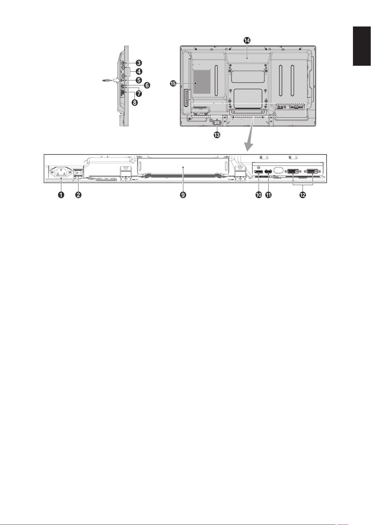
Terminal Panel
From option control unit
A AC IN connector
Connects with the supplied power cord.
B Main Power Switch
On/OffswitchtoturnmainpowerON/OFF.
C LAN port (RJ-45)
LAN connection. See page 32.
D RS-232C (D-Sub 9 pin)
IN connector:ConnectRS-232Cinputfromexternal
equipment such as a computer in order to control RS-232C
functions.
OUT connector: Connect RS-232C output. To connect
multiple MultiSync monitors via RS-232C daisy Chain.
E REMOTE IN
Use the optional wired remote control by connecting it to your
monitor.
NOTE: When you use Remote IN, IR CONTROL in OSD
menu should be NORMAL.
NOTE: Do not use this connector unless specified.
F AUDIO OUT
To output the audio signal from the AUDIO IN 1, DPORT and
HDMItoanexternaldevice(stereoreceiver,amplier,etc.).
NOTE: This connector is not a headphone terminal.
G AUDIO IN 1
Toinputaudiosignalfromexternalequipmentsuchasa
computer, VCR or DVD player.
H VGA IN (mini D-Sub 15 pin)
To input analog RGB signals from a personal computer or
from other RGB equipment. This input can be used with an
RGB, COMPONENT, SCART, VIDEO or S-VIDEO source.
Please select signal type in TERMINAL SETTING.
See page 25.
NOTE: When you use this connector for COMPONENT,
SCART, VIDEO or S-VIDEO, please use a suitable signal
cable. If you have any questions, please ask your dealer.
I Option board slot
Slot 2 type accessories are available. Please contact your
supplier for detailed information.
NOTE: Please contact your supplier for available option
board.
J DISPLAYPORT connector
To input DisplayPort signals.
K HDMI connector
To input digital HDMI signals.
L DVI connector (DVI-D)
IN connector: To input digital RGB signals from a computer
or HDTV device having a digital RGB output.
* This connector does not support analog input.
OUT connector: To output the DVI signal from DVI IN or
HDMI with DVI signal input. (DVI signal only, HDMI signal is
not thorough out).
M Security Slot
Security and theft protection lock slot compatible with
Kensingtonsecuritycables/equipment.
For products, visit Kensington’s website.
N Internal speaker
O Rating label
English-10
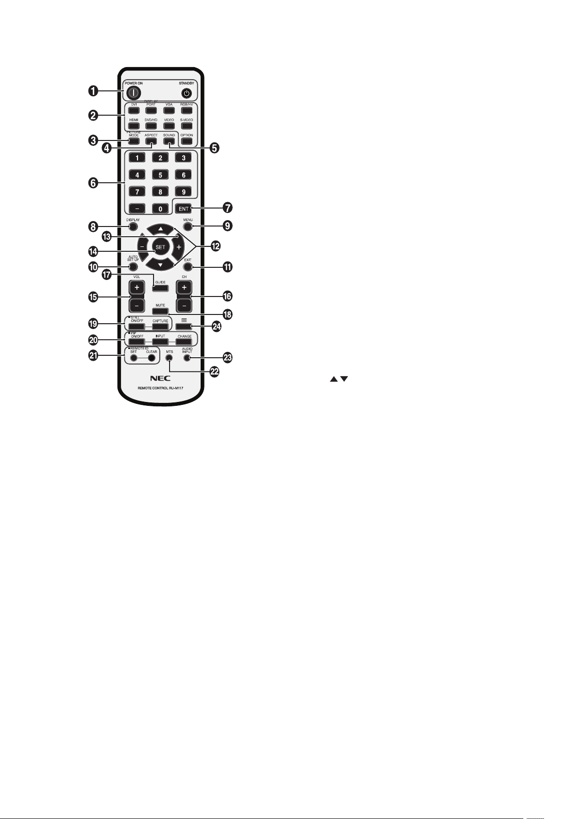
Wireless Remote Control
A POWER button
Switchesthepoweron/standby.
B INPUT button
Selects input signal.
DVI: DVI
DISPLAYPORT: DPORT
VGA: VGA
HDMI: HDMI
DVD/HD:DVD/HD,SCART
VIDEO: VIDEO
S-VIDEO: S-VIDEO
OPTION: Depends on your connection
C PICTURE MODE button
Selects picture mode, [HIGHBRIGHT], [STANDARD],
[sRGB], [CINEMA], [AMBIENT1], [AMBIENT2]. See page 18.
HIGHBRIGHT: for moving images such as DVD.
STANDARD: for images.
sRGB:fortextbasedimages.
CINEMA: for movies.
AMBIENT1 and AMBIENT2: activate auto dimming
function. See page 18.
D ASPECT button
Selects picture aspect, [FULL], [WIDE], [DYNAMIC], [1:1],
[ZOOM] and [NORMAL]. See page 17.
E SOUND button
Articialsurroundsoundforinternal/externalspeakers.
Audio out is disabled when surround is set to ON.
F KEYPAD
Press buttons to set and change passwords, change channel
and set REMOTE ID.
G ENT button*
2
H DISPLAY button
Turnson/offtheinformationOSD.Seepage18.
I MENU button
Turnson/offthemenumode.
J AUTO SETUP button
Enters auto setup menu. See page 20.
K EXIT button
Returns to previous menu within OSD menu.
L UP/DOWN button
Acts as
button to move the highlighted area up or down
to select adjustment items within OSD menu.
Small screen which adjusted “PIP” mode moves up or down.
M MINUS/PLUS (-/+) button
Increases or decreases the adjustment level within OSD
menu settings.
Small screen which adjusted “PIP” mode moves left or right.
N SET button
Makes selection.
O VOLUME UP/DOWN button
Increases or decreases audio output level.
P CH UP/DOWN button*
2
Q GUIDE button*
2
R MUTE button
Turnson/offmutefunction.
S STILL button
ON/OFF button:Activates/deactivatesstillpicturemode.
STILL CAPTURE button: Captures still picture.
English-11
English
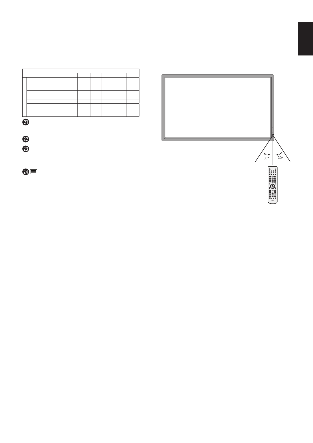
Operating Range for the Remote
Control
Points the top of the remote control toward the LCD monitor’s
remote sensor during button operation.
Uses the remote control within a distance of about 7 m (23 ft.)
fromremotecontrolsensororatahorizontalandvertical
angleofwithin30°withinadistanceofabout3.5m(10ft.).
T PIP (Picture In Picture) button
ON/OFF button: Toggle switches between PIP, POP,
PICTURE BY PICTURE-ASPECT and PICTURE BY
PICTURE-FULL. See page 22.
INPUT button: Selects the “picture in picture” input signal.
CHANGE button: Replaces to the main picture and sub
picture.
Sub picture
DVI DPORT VGA HDMI DVD/HDSCART VIDEO S-VIDEO OPTION
Main picture
DVI
No Yes Yes No Yes Yes Yes Yes No
DPORT
Yes No Yes Yes Yes Yes Yes Yes Yes
VGA
Yes Yes No Yes No No No No Yes
HDMI
No Yes Yes No Yes Yes Yes Yes No
DVD/HD
Yes Yes No Yes No No No No Yes
SCART
Yes Yes No Yes No No No No Yes
VIDEO
Yes Yes No Yes No No No No Yes
S-VIDEO
Yes Yes No Yes No No No No Yes
OPTION
No Yes Yes No Yes Yes Yes
Yes
No
REMOTE ID button
Activates REMOTE ID function.
MTS button*
2
AUDIO INPUT button
Selects audio input source [IN1], [DPORT], [HDMI],
[OPTION]*
1
.
button
Activates closed captioning.
Note: VIDEO, S-VIDEO inputs only.
*1: The product you purchased may not have this feature.
*2: This button’s action depends on which option board you use.
Refer to the option board’s manual for further information.
Caution: Important, the remote control
system may not function
when direct sunlight or strong
illumination strikes the remote
control sensor or when there is
an object in the path.
Handling the remote control
•Donotsubjecttostrongshock.
•Donotallowwaterorotherliquidtosplash
the remote control. If the remote control gets
wet, wipe it dry immediately.
•Avoidexposuretoheatandsteam.
•Otherthantoinstallthebatteries,donotopentheremote
control.
English-12
1. Determine the installation location
CAUTION: Installing your LCD monitor must be done by a
qualified technician. Contact your dealer for more
information.
CAUTION:
MOVING OR INSTALLING THE LCD MONITOR
MUST BE DONE BY TWO OR MORE PEOPLE.
Failure to follow this caution may result in injury if
the LCD monitor falls.
CAUTION: Do not mount or operate the monitor upside
down.
CAUTION: This LCD has a temperature sensor and cooling
fans, including a fan for option board.
If the LCD becomes too hot, the cooling fans will
turn on automatically.
The fan of option board is active although the
temperature is lower than normal operating
temperature for cooling option board. If the LCD
becomes overheated while the cooling fan is
running, a “Caution” warning will appear. If the
“Caution” warning appears, discontinue use and
allow the unit to cool. Using the cooling fan will
reduce the likelihood of early circuit failure and
may help reduce image degradation and “Image
Persistance”.
If the LCD is used in an enclosed area or if the
LCD panel is covered with a protective screen,
please check the inside temperature of the
monitor by using the “HEAT STATUS” control
in the OSD (see page 24). If the temperature is
higher than the normal operating temperature,
please turn the cooling fan to ON within the FAN
CONTROL menu within the OSD (see page 24).
IMPORTANT: Lay the protective sheet, which was wrapped
around the LCD monitor when it was
packaged, beneath the LCD monitor so as not
to scratch the panel.
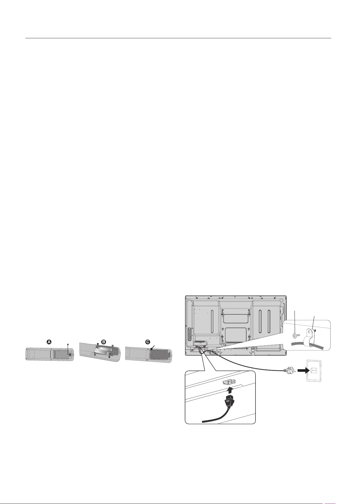
2. Install the remote control batteries
The remote control is powered by two 1.5V AA batteries.
To install or replace batteries:
A. Press and slide to open the cover.
B. Align the batteries according to the (+) and (–) indications
inside the case.
C. Replace the cover.
CAUTION: Incorrect usage of batteries can result in leaks or
bursting.
NEC recommends the following battery use:
•Place“AA”sizebatteriesmatchingthe(+)and(-)signs
on each battery to the (+) and (-) signs of the battery
compartment.
•Donotmixbatterybrands.
•Donotcombinenewandoldbatteries.Thiscanshorten
battery life or cause liquid leakage of batteries.
•Removedeadbatteriesimmediatelytopreventbattery
acid from leaking into the battery compartment.
•Donottouchexposedbatteryacid,itmayinjureskin.
NOTE: If you do not intend to use the Remote Control for
a long period of time, remove the batteries.
3. Connect external equipment
(See page 14 and page 15)
•Toprotecttheexternalequipment;turnoffthemainpower
before making connections.
•Refertoyourequipmentusermanualforfurther
information.
NOTE: Donotconnect/disconnectcableswhenturning
onthemonitororotherexternalequipmentasthis
may result in a loss of the monitor image.
4. Connect the supplied power cord
•Theequipmentshouldbeinstalledclosetoaneasily
accessible power outlet.
•Fullyinserttheprongsintothepoweroutletsocket.
A loose connection may cause image degradation.
•PleasefastenpowercordtotheLCDmonitorbyattaching
the screw and clamp.
NOTE: Please refer to the “Important Information” section
of this manual for proper selection of AC power
cord.
Screw
Clamp
Setup

English-13
English
5. Cable Information
CAUTION: Use the provided specified cables with this
product so as not to interfere with radio and
television reception.
For DVI and mini D-Sub 15-pin, please use a
shielded signal cable with ferrite core.
For D-Sub 9-Pin, HDMI and DisplayPort,
please use a shielded signal cable.
Use of other cables and adapters may
cause interference with radio and television
reception.
6. Switch on the power of all the attached
external equipment
When connected with a computer, switch on the power of the
computer first.
7. Operate the attached external equipment
Display the signal from the desired input source.
8. Adjust the sound
Make volume adjustments when required.
9. Adjust the screen (See page 20 and
page 21)
Make adjustments of the screen display position when
necessary.
10. Adjust the image (See page 20)
Make adjustments such as backlight or contrast when
required.
11. Recommended Adjustments
To reduce the risk of the “Image Persistence”, please adjust
the following items based on the application being used:
“SCREEN SAVER”, “SIDE BORDER COLOR” (See page 25)
“DATE & TIME”, “SCHEDULE SETTINGS” (See page 21).
It is recommended that the “FAN CONTROL” setting
(See page 24) be turned to ON also.
English-14
Connections
NOTE: Donotconnect/disconnectcableswhenturningonthemonitororotherexternalequipmentasthismayresultina
loss of the monitor image.
NOTE: Use an audio cable without a built-in resistor. Using an audio cable with a built-in resistor turns down the sound.
Before making connections:
* First turn off the power of all the attached equipment and make connections.
* Refer to the user manual included with each separate piece of equipment.
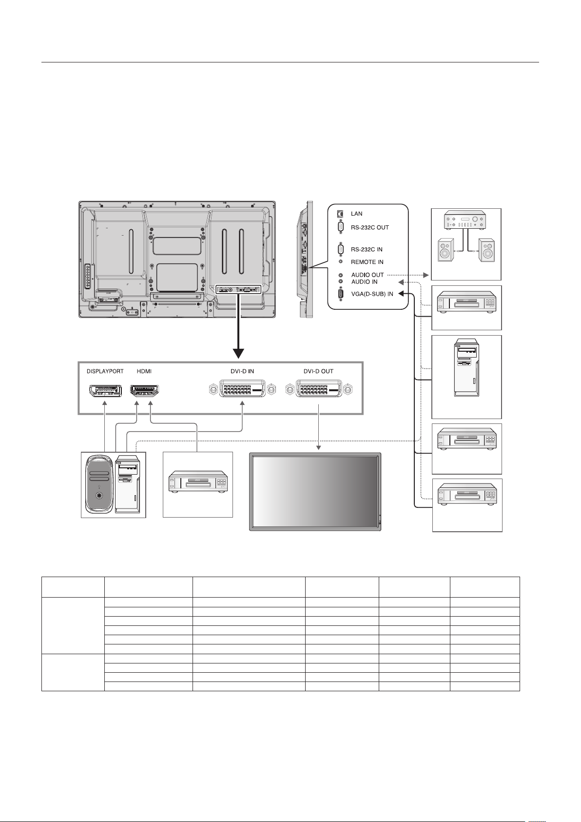
Wiring Diagram
Solid lines = video signal
Dotted lines = audio signal
DVD player
with HDMI out
VCR or DVD player
Stereo Amplifier
Second monitor*
Computer (Analog)
Computer (Digital)
DVD player with
SCART OUT
DVD player
*
2
*: Multiple monitors that are daisy-chained have a limit to the connectable monitors.
Connected
equipment
Connecting
terminal
Setting in Terminal Mode Input signal name
Connecting
Audio terminal
Input button
in remote control
AV
DVI (DVI-D) DVI MODE: DVI-HD DVI AUDIO IN1 DVI
HDMI RAW/EXPAND*
1
HDMI HDMI HDMI
VGA (D-Sub) D-SUB MODE: SCART SCART AUDIO IN1 DVD/HD
VGA (D-Sub) D-SUB MODE: S-VIDEO S-VIDEO AUDIO IN1 S-VIDEO
VGA (D-Sub) D-SUB MODE: VIDEO VIDEO AUDIO IN1 VIDEO
VGA (D-Sub) D-SUB MODE: COMPONENT DVD/HDAUDIO IN1 DVD/HD
Computer
VGA (D-Sub) - VGA AUDIO IN1 VGA
DVI (DVI-D) DVI MODE: DVI-PC DVI AUDIO IN1 DVI
DisplayPort - DPORT DPORT DISPLAYPORT
HDMI RAW/EXPAND*
1
HDMI HDMI HDMI
*1: Depends on signal type.
*2: A special cable is required. Contact your dealer for more information.

English-15
English
Connecting a Personal Computer
Connecting your computer to your LCD monitor will enable you to display your computer’s screen image.
Somedisplaycardswithapixelclockover162MHzmaynotdisplayanimagecorrectly.
Your LCD monitor displays proper image by adjusting the factory preset timing signal automatically.
<Typical factory preset signal timing>
Resolution
Scanning frequency Remarks
HorizontalVertical
640x48031.5kHz60Hz
800x60037.9kHz60Hz
1024x76848.4kHz60Hz
1280x76848kHz60Hz
1360x76848kHz60Hz
1280x102464kHz60Hz
1600x120075kHz60HzCompressed image
1920x108067.5kHz60HzRecommended resolution
•InputTMDSsignalsconformingtoDVIstandards.
•Tomaintaindisplayquality,useacablethatconformstoDVIstandards.
Connecting a DVD Player or Computer with HDMI out
•PleaseuseanHDMIcablewithHDMIlogo.
•Itmaytakeamomentforthesignaltoappear.
•Somedisplaycardsordriversmaynotdisplayanimagecorrectly.
Connecting a Computer with DisplayPort
•PleaseuseDisplayPortcablewithDisplayPortcompliancelogo.
•Itmaytakeamomentforthesignaltoappear.
•PleasenotethatDisplayPortconnectordoesnotsupplypowertotheconnectedcomponent.
•PleasenotethatwhenconnectingaDisplayPortcabletoacomponentwithasignalconversionadapter,animagemaynot
appear.
•SelectDisplayPortcablesfeaturealockingfunction.Whenremovingthiscable,holddownthetopbuttontoreleasethelock.
English-16
Basic Operation
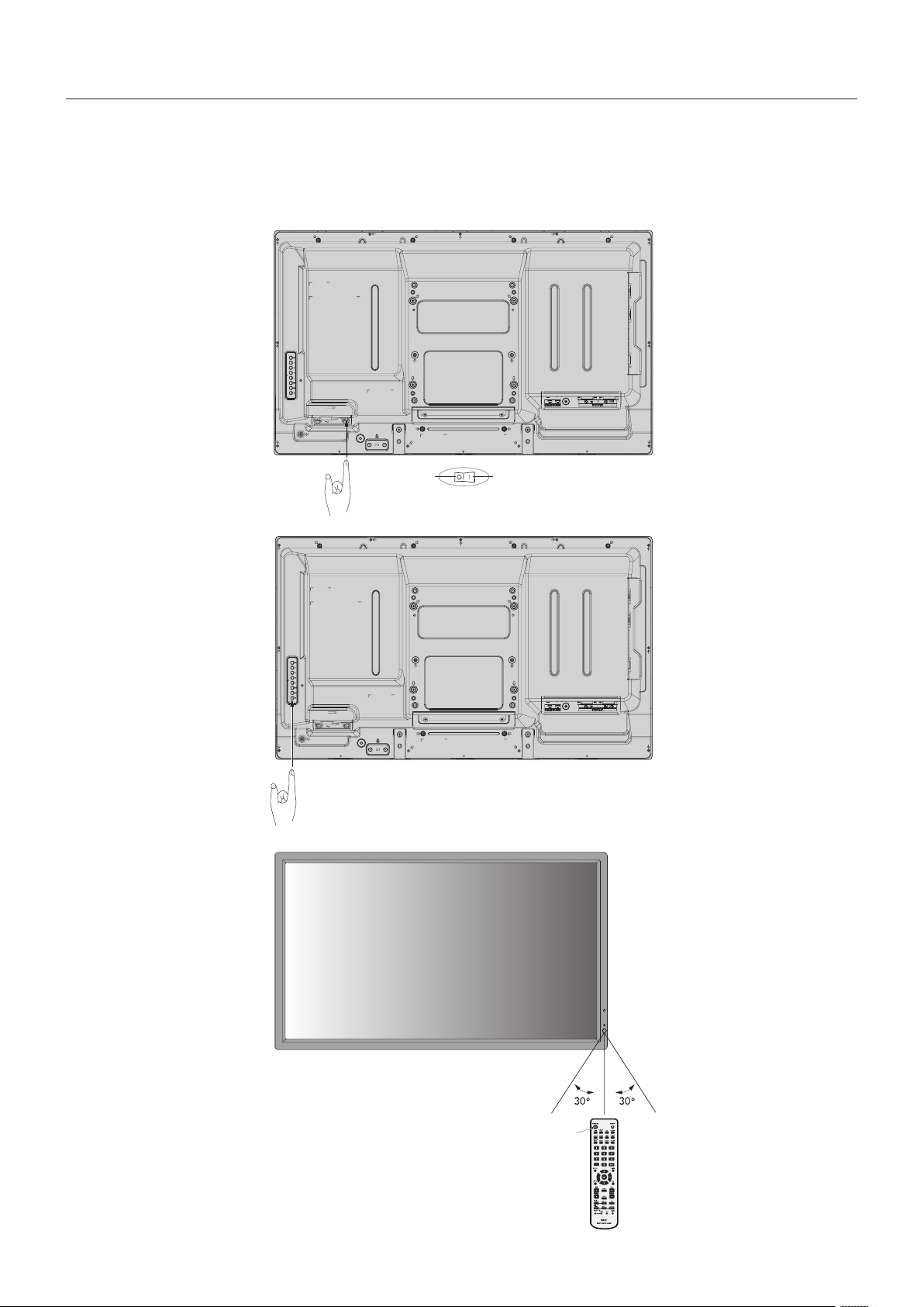
Power ON and OFF Modes
The LCD monitor power indicator will turn green while powered on and will turn red or amber while powered off.
NOTE: The Main Power Switch must be in the ON position in order to power up the monitor using the remote control or the
Power Button.
Main Power Switch
ONOFF
Power Button
Using the remote control
POWER ON Button

English-17
English
Picture Aspect
DVI, VGA, DPORT
FULL
1:1 ZOOM NORMAL
HDMI,DVD/HD,SCART,VIDEO,S-VIDEO
FULL
WIDE DYNAMIC 1:1 ZOOM NORMAL
Aspect ratio
of image
Unchanged view*
3
Recommended selection
for picture aspect*
3
4:3
NORMAL
DYNAMIC
Squeeze
FULL
Letterbox
WIDE
*
3
Grey areas indicate unused portions of the screen.
NORMAL: Displays the aspect ratio the same as it is sent
from the source.
FULL: Fills entire screen.
WIDE:Expandsa16:9letterboxsignaltollentirescreen.
DYNAMIC:Expandsa4:3picturestolltheentirescreen
with non-linearity. Some of the outside image area will be cut
offduetoexpansion.
1:1: Displaystheimageina1by1pixelformat.
ZOOM
Theimagecanbeexpanded/reducedbeyondtheactive
display area. The image which is outside of active display
area is not shown.
ZOOM
ZOOM
Power Indicator
Mode Status Indicator Light
Power ON Green*
1
Power OFF and Power Save “AUTO
STANDBY”
Power consumption under 0.5 W*
2
Red
Power Save “POWER SAVE”
Power consumption under 1 W
Amber
Power Standby when “SCHEDULE
SETTINGS” enabled
Green and Amber blink alternately
Diagnosis (Detecting failure) Red Blinking
(See Troubleshooting page 38)
*1 If “OFF” is selected in POWER INDICATOR (page 24), the LED will not light when the
LCD monitor is in active mode.
*2 Without any option, with factory settings, VGA input only.
Using Power Management
The LCD monitor follows the VESA approved DPM Display
Power Management function.
The power management function is an energy saving
function that automatically reduces the power consumption
of the display when the keyboard or the mouse has not been
usedforaxedperiod.
The power management feature on your new display has
been set to the “AUTO STANDBY” mode. This allows your
display to enter a Power Saving Mode when no signal is
applied. This could potentially increase the life and decrease
the power consumption of the display.
NOTE: Depending on the computer and display card
used, this function may not operate.
NOTE: When POWER SAVE is ON (see page 24), the
monitor goes into power management mode, it
takes about several seconds for HDMI and about
10minutesforDVD/HD,SCART,VIDEOand
S-VIDEO.
Selecting a video source
To view a video source:
Use the input button to set [VIDEO], [S-VIDEO].
Use the COLOR SYSTEM menu to set [AUTO], [NTSC],
[PAL], [SECAM], [PAL60], [4.43NTSC], according to your
video format.
English-18
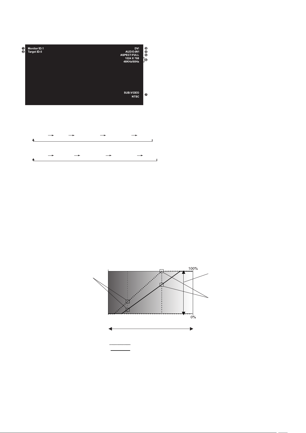
Information OSD
TheInformationOSDprovidesinformationsuchas:MonitorID,InputSource,PictureSize,etc.
Press the DISPLAY button on the remote to bring up the Information OSD.
1
ID number assigned to current monitor*
1
2
ID number assigned monitor to be controlled via RS-232C*
2
3
Input Name
4
Audio input mode
5
Picture aspect
6
Input Signal Information
7
Sub picture information
*1: “IR CONTROL” should be set “Primary” or “Secondary”.
*2: “IR CONTROL” should be set “Primary”.
Picture Mode
DVI, VGA, DPORT
STANDARD
sRGB AMBIENT1 AMBIENT2 HIGHBRIGHT
HDMI,DVD/HD,SCART,VIDEO,S-VIDEO
STANDARD CINEMA AMBIENT1 AMBIENT2 HIGHBRIGHT
AMBIENT Mode
The backlight of the LCD screen can be set to increase or decrease depending on the amount of ambient light within the room.
If the room is bright, the monitor becomes correspondingly bright. If the room is dim, then the monitor will dim accordingly. The
purposeofthisfunctionistomaketheviewingexperiencemorecomfortabletotheeyeinavarietyoflightingconditions.
NOTE: When picture mode is set to AMBIENT1 or AMBIENT2, BACKLIGHT, AUTO BRIGHTNESS and BACKLIGHT in
SCREEN SAVER function are disabled.
Do not cover Ambient light sensor when you use AMBIENT1 or AMBIENT2 in PICTURE MODE.
AMBIENT parameter setting
PICTURE MODE in OSD, select AMBIENT1 or AMBIENT2 and set IN BRIGHT and IN DARK in each mode.
IN BRIGHT: This is the backlight level that the monitor will go up to when the ambient light level is highest.
IN DARK: This is the level of backlight that the monitor will go down to when the ambient light level is low.
When the AMBIENT function is enabled the Backlight level of the screen changes automatically according to the lighting
conditions of the room (Figure 1).
BACKLIGHT level set
for the monitor to use
when ambient lighting
level is low.
BACKLIGHT level set for the
monitor to use when ambient
lighting level is high.
BACKLIGHT range
Figure 1
dark bright
room bright condition
Screen Backlight value by AMBIENT2 mode
IN DARK IN BRIGHT
Screen Backlight value by AMBIENT1 mode
Factory Setting
IN DARK: BACKLIGHT level set for the monitor to use when ambient lighting level is low.
IN BRIGHT: BACKLIGHT level set for the monitor to use when ambient lighting level is high.
English-19
English
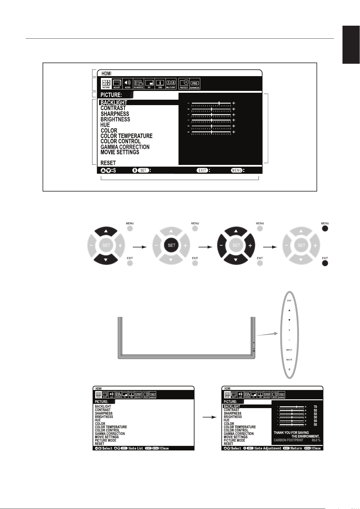
OSD (On-Screen-Display) Controls
NOTE: Some functions may not be available depending on the model or optional equipment.
PICTURE MODE
Goto Adjustment
Select
Return Close
70
50
50
50
50
50
THANK YOU FOR SAVING
THE ENVIRONMENT.
CARBON FOOTPRINT 86.0 %
Input source
Main Menu Icons
Main Menu Item
Sub Menu
Key Guide
Adjustment Settings
Remote Control
Press UP or DOWN
button to select
sub-menu.
Press SET. Press UP or DOWN,
PLUS or MINUS to select
the function or setting to
be adjusted.
Press MENU or EXIT.
Press UP or DOWN
button to select.
Press INPUT button
to decide.
Press UP or DOWN, PLUS
or MINUS button to select.
Press EXIT
Control Panel
OSD screen
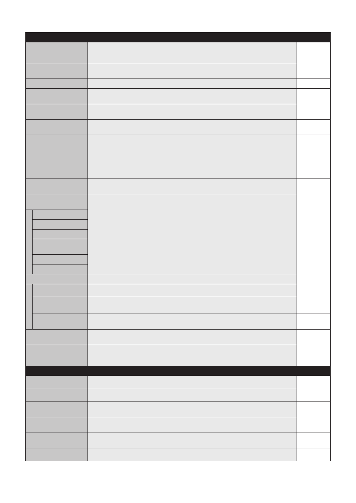
English-20
Setting Default
PICTURE
BACKLIGHT Adjusts the overall image and background brightness. Press + or - to adjust.
Note: When AMBIENT1 or AMBIENT2 is selected in picture mode, this function cannot be
changed.
Depends on
destination
CONTRAST Adjusts the image brightness in relationship to the input signal. Press + or - to adjust.
Note: When sRGB is selected in picture mode, this function cannot be changed.
50
SHARPNESS Adjusts the crispness of the image. Press + or - to adjust. 50*
BRIGHTNESS Adjusts the image brightness in relationship to the background. Press + or - to adjust.
Note: When sRGB is selected in picture mode, this function cannot be changed.
50
HUE Adjusts the hue of the screen. Press + or - to adjust.
Note: When sRGB is selected in picture mode, this function cannot be changed.
50
COLOR Adjusts the color depth of the screen. Press + or - to adjust.
Note: When sRGB is selected in picture mode, this function cannot be changed.
50*
COLOR TEMPERATURE Adjusts the color temperature of the entire screen. A low color temperature will make the screen
reddish. A high color temperature will make the screen bluish. If TEMPERATURE needs further
adjustment,theindividualR/G/B/levelsofthewhitepointcanbeadjusted.ToadjusttheR/G/B
levels, CUSTOM must be showing as the COLOR TEMP selection.
Note: When sRGB is selected in picture mode, predefined 6500k is set so it cannot be changed.
When PROGRAMMABLE is selected in GAMMA CORRECTION, this function cannot be
changed.
10000K
COLOR CONTROL Adjusts the hue of the Red, Yellow, Green, Cyan, Blue and Magenta.
Note: When sRGB is selected in picture mode, this function cannot be changed.
0
GAMMA CORRECTION Select a display gamma for best picture quality.
Note: When sRGB is selected in picture mode, this function cannot be changed.
NATIVE*
(exceptsRGB
setting)
NATIVE Gamma correction is handled by the LCD panel.
2.2 Typical display gamma for use with a computer.
2.4 Good for video (DVD, etc.)
S GAMMA Special gamma for certain types of movies. Raises the dark parts and lowers the light parts of the
image (S-Curve).
DICOM SIM. DICOM GSDF curve simulated for LCD type.
PROGRAMMABLE A programmable gamma curve can be loaded using NEC optional software.
MOVIE SETTINGS
NOISE REDUCTION
VIDEO, S-VIDEO inputs only
Adjusts the amount of noise reduction. Press + or - to adjust. 0*
TELECINE
HDMI,DVD/HD,SCART,VIDEO,S-VIDEO
inputs only
Automatically senses the sources frame rate for optimal picture quality. AUTO*
ADAPTIVE CONTRAST
HDMI,DVD/HD,SCART,VIDEO,S-VIDEO
inputs only
Sets the level of adjustment for dynamic contrast. OFF
PICTURE MODE Selects picture mode, [HIGHBRIGHT], [STANDARD], [sRGB], [CINEMA], [AMBIENT1] or
[AMBIENT2]. See page 18.
Depends on
destination
RESET Resets the following settings within the PICTURE menu back to factory setting: BACKLIGHT,
CONTRAST, SHARPNESS, BRIGHTNESS, HUE, COLOR, COLOR TEMPERATURE,
COLOR CONTROL, GAMMA CORRECTION, MOVIE SETTINGS.
-
ADJUST
AUTO SETUP
VGA input only
AutomaticallyadjustsScreenSize,Hposition,Vposition,Clock,PhaseandWhiteLevel.-
AUTO ADJUST
VGA input only
H Position, V Position and Phase are adjusted automatically when new timing is detected. OFF
H POSITION
AllinputsexceptDVI,HDMI,DPORT
ControlsthehorizontalpositionoftheimagewithintheDisplayareaoftheLCD.
Press + to move right. Press - to move left.
-
V POSITION
AllinputsexceptDVI,HDMI,DPORT
Controls the vertical position of the image within the Display area of the LCD.
Press + to move up. Press - to move down.
-
CLOCK
VGA input only
Press+toexpandthewidthoftheimageontherightofthescreen.
Press - to narrow the width of the image on the left.
-
PHASE
VGA,DVD/HD,SCARTinputsonly
Adjusts the visual “noise” on the image. -
*: depends on signal input
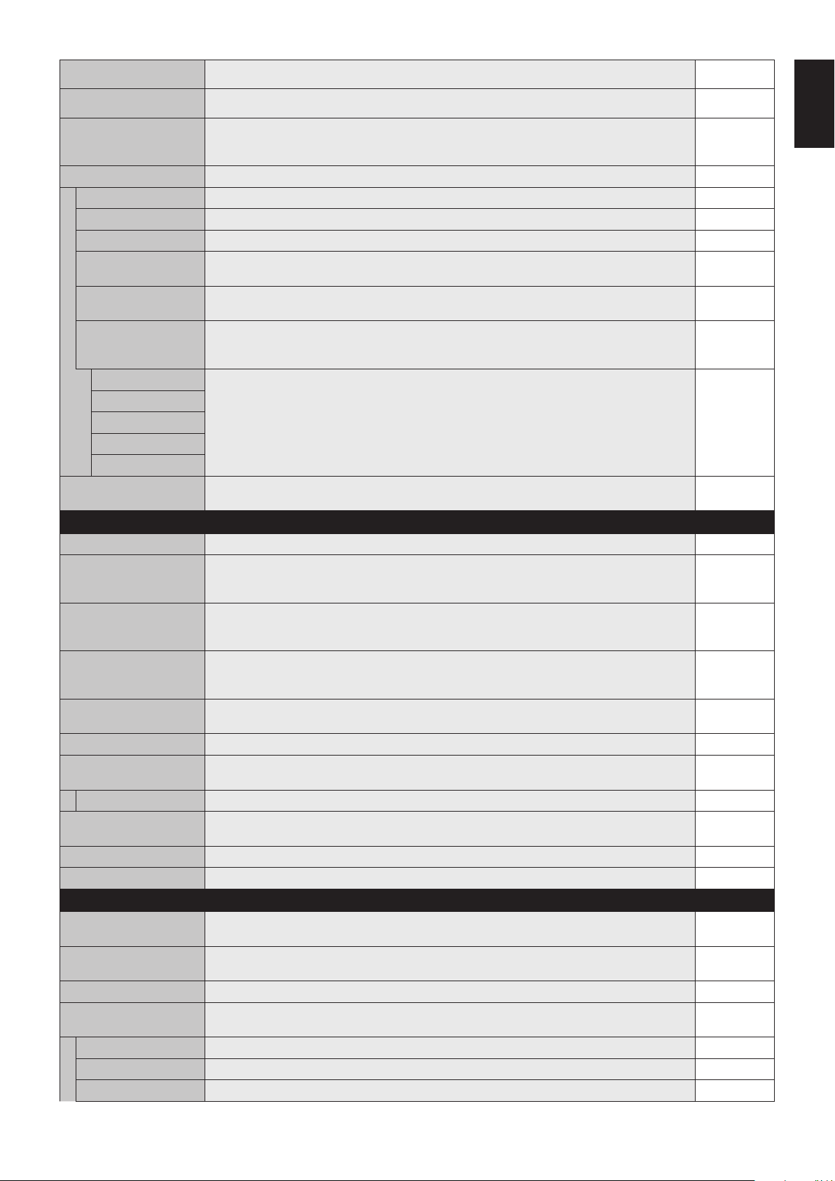
English-21
English
H RESOLUTION
VGA input only
Adjuststhehorizontalsizeoftheimage.-
V RESOLUTION
VGA input only
Adjuststheverticalsizeoftheimage.-
INPUT RESOLUTION
VGA input only
If there is a problem with signal detection, this function forces the monitor to display the signal at
thedesiredresolution.Afterselection,execute“AUTOSETUP”ifrequired.
If no problem is detected, the only available option will be “AUTO”.
AUTO
ASPECT Select the aspect ratio of the screen image. FULL
NORMAL Displays the aspect ratio the same as it is sent from the source. -
FULL Fills entire screen. -
WIDE Expandsa16:9letterboxsignaltollentirescreen.-
DYNAMIC Expandsa4:3picturestolltheentirescreenwithnon-linearity.Someoftheoutsideimagearea
willbecutoffduetoexpansion.TILEMATRIXbecomesinvalid.
-
1:1 Displaytheimageina1by1pixelformat.(Iftheinputresolutionishigherthana1920x1080
resolution, the image will be scaled down to fit the screen). TILE MATRIX becomes invalid.
-
ZOOM Theimagecanbeexpanded/reduced.
Note:Theexpandedimagewhichisoutsideofactivedisplayareaisnotshown.Thereduced
image may have some image degradation.
-
ZOOM Maintainstheaspectratiowhilezooming.-
H ZOOM Amountofhorizontalzoom.
V ZOOM Amountofverticalzoom.
H POS Horizontalposition.
V POS Vertical position.
RESET Resets the following settings within the ADJUST menu back to factory setting: AUTO ADJUST,
H POSITION, V POSITION, CLOCK, PHASE, H RESOLUTION, V RESOLUTION, ASPECT.
-
AUDIO
VOLUME Increases or decreases output volume level. 40
BALANCE
AdjustthebalanceofL/Rvolume.
Press + button to move the stereo sound image to right.
Press - button to move the stereo sound image to left.
CENTER
TREBLE To accentuate or reduce the high frequency sound.
Press + button to increase TREBLE sound.
Press - button to decrease TREBLE sound.
0
BASS To accentuate or reduce the low frequency sound.
Press + button to increase BASS sound.
Press - button to decrease BASS sound.
0
SURROUND Artificial surround sound.
Note: Audio out is disabled when this function is set to ON.
OFF
PIP AUDIO Selects source of PIP audio. MAIN AUDIO
LINE OUT Selecting “VARIABLE” enables control of the line out level with the VOLUME button.
Note: Audio out is disabled when this function is set to ON.
FIXED
INTERNAL SPEAKER Selecting “OFF” enables internal speaker output is turned off. ON
AUDIO INPUT Selects audio input source [IN1], [DPORT], [HDMI], [OPTION]*. Depend on
signal input
AUDIO DELAY (not adjustable) -
RESET Resets“AUDIO”optionsbacktofactorysettingsexceptVOLUME.-
SCHEDULE
OFF TIMER Sets the monitor to power off after a length of time.
A time between 1 to 24 hours is available.
OFF
SCHEDULE SETTINGS Creates a working schedule for the monitor to use.
NOTE: If your schedule is across date, please set ON time and OFF time individually at Settings.
-
SCHEDULE LIST List of schedules. -
DATE & TIME Sets the date, time, and daylight saving region. Date & time must be set in order for the
“SCHEDULE” function to operate. See page 27.
YEAR Configures the year for the real time clock. -
MONTH Configures the month for the real-time clock. -
DAY Configures the day for the real-time clock. -
*: The product you purchased may not have this feature.
English-22
TIME Configures the time for the real-time clock. -
DAYLIGHT SAVING Configures daylight savings on or off. OFF
RESET Resets the following settings within the SCHEDULE menu back to factory setting: OFF TIMER
and SCHEDULE SETTINGS.
-
PIP*
KEEP PIP MODE Allows the monitor to remain in “PIP” and “TEXT TICKER” mode after powering off.
When Power is returned, PIP and TEXT TICKER appear without having to enter the OSD.
OFF
PIP MODE Selects Picture-in-Picture mode. OFF
OFF Normal mode.
PIP Picture in Picture mode.
POP Picture out Picture mode.
PICTURE BY PICTURE-
ASPECT
Picture by picture (split screen) mode, with keep aspect.
PICTURE BY PICTURE
-
FULL
Picture by picture (split screen) mode, with full screen.
PIP SIZE Selectsthesizeofthesub-pictureusedinPicture-in-Picture(PIP)mode.LARGE
SMALL
MIDDLE
LARGE
PIP POSITION Determines where the PIP appears on the screen. X = 95, Y = 92
ASPECT Selects sub picture aspect, [FULL], [NORMAL] and [WIDE]. See page 17. FULL
TEXT TICKER OFF
MODE EnablesTextTickerandallowsyoutosetHorizontalorVerticaldirection.
POSITION SelectsthelocationoftheTextTickeronthescreen.
SIZE DeterminesthesizeoftheTextTickerinrelationshiptotheoverallscreensize.
BLEND SetsthetransparencyoftheTextTicker(0:transparent,100:opaque).
DETECT Enablesauto-detectionoftheTextTicker.
FADE IN Enablesfade-inofthetextticker.
SUB INPUT Selects sub picture input signal. Depends on
signal input
RESET ResetsPIPoptionsbacktofactorysettingsexceptASPECTandSUBINPUT.-
OSD
LANGUAGE Select the language used by the OSD. ENGLISH
(Depends on
destination)
ENGLISH
DEUTSCH
FRANÇAIS
ITALIANO
ESPAÑOL
SVENSKA
РУССКИЙ
MENU DISPLAY TIME Turns off the OSD after a period of inactivity. The preset choices are 10-240 seconds. 30 Sec.
OSD POSITION Determines the location where the OSD appears on the screen.
X = 128, Y = 225
UP
DOWN
LEFT
RIGHT
*: If RESPONSE IMPROVE is set to “MODE 1” or “MODE 2”, PIP function is not available.
English-23
English
INFORMATION OSD Selects whether the information OSD is displayed or not. The information OSD will be displayed
when the input signal or source changes. The information OSD will also give a warning when
there is no-signal or the signal is out-of range.
An interval between 3 to 10 seconds for the Information OSD to appear is available.
ON, 3 Sec.
MONITOR INFORMATION Indicates the model and serial number of your monitor.
CARBON SAVINGS: Display the estimated carbon saving information in kg-CO2. The carbon
footprint factor in the carbon saving calculation is based on the OECD (2008 Edition).
CARBON USAGE: Display the estimated carbon usage information in kg-CO2. This is the
arithmetic estimation, not actual measurement value. This estimation is based without any options.
-
OSD TRANSPARENCY Set the transparency of the OSD. ON
OSD ROTATION Determines the OSD display direction between landscape and portrait. LANDSCAPE
LANDSCAPE Display the OSD with landscape mode.
PORTRAIT Display the OSD with portrait mode.
INPUT NAME You can create a name for the INPUT currently being used.
Max:8characters,includingSpace,A-Z,0-9,andsomesymbols.
-
CLOSED CAPTION
VIDEO, S-VIDEO inputs only
Activates closed captioning. OFF
RESET Resets the following settings within the OSD menu back to factory setting: MENU DISPLAY
TIME, OSD POSITION, INFORMATION OSD, OSD TRANSPARENCY, CLOSED CAPTION.
-
MULTI DISPLAY
CONTROL ID Sets the monitor ID number from 1-100 and group ID from A-J. When “YES” is selected in
“AUTO ID”, monitor ID numbers are set automatically in all monitors which follow in the chain with
RS-232C.
NOTE: Group ID is made of multiple selections.
1
IR CONTROL Selects the mode of the monitor for use with the infra-red remote control when using the
RS-232C daisy chain.
NORMAL
NORMAL The monitor will be controlled normally using the wireless remote control.
PRIMARY Choose “PRIMARY” for the first monitor within an RS-232C daisy chain.
SECONDARY Choose “SECONDARY” for all subsequent monitors within an RS-232C daisy chain.
IR LOCK SETTINGS Prevents the monitor from being controlled by the wireless remote control.
When ACTIVATE is selected, all the settings are activated.
NOTE: IR LOCK SETTINGS is a function intended only to the wireless remote control buttons.
This function does not lock out access to all buttons at the back of the monitor. To return to
normal operation, press the “DISPLAY” button on the remote control for 5 seconds.
UNLOCK
MODE SELECT Selects the mode UNLOCK, ALL LOCK or CUSTOM LOCK.
UNLOCK All buttons on the remote control are available for normal operations.
ALL LOCK Locks all remote control buttons.
CUSTOM LOCK Selects which buttons to be locked from POWER, VOLUME, and INPUT button.
ExceptforCUSTOMLOCKsettings,otherbuttonsontheremotecontrolarelocked.
POWER: When LOCK is selected, POWER button is locked.
VOLUME:WhenUNLOCKisselected,setsminimumandmaximumvolumebetweenVOL.0to
VOL.100.
VOLUME (+) button and VOLUME (-) buttons are only available from the minimum
volumetothemaximumvolumeyouset.
When LOCK is selected, VOLUME (+) button and VOLUME (-) buttons are locked.
INPUT: When UNLOCK is selected, choose up to three buttons from DVI, DisplayPort, VGA,
HDMI,DVD/HD*
2
, VIDEO*
2
, S-VIDEO*
2
, OPTION*
1
which you prefer to be unlocked.
The unselected buttons are locked. When LOCK is selected, all INPUT buttons are
locked.
TILE MATRIX Allowsoneimagetobeexpandedanddisplayedovermultiplescreens(upto100)througha
distribution amplifier.
NOTE: Low resolution is not suitable for tiling to a large number of monitors. You can operate
without a distribution amplifier at a lower number of screens.
Dynamicor1:1willnotworkwhenTileMatrixisactivated.When“DYNAMIC”or“1:1isselected
inASPECTwhileexecutingTILEMATRIX,thesettingwillbeappliedafterTILEMATRIX
completion.
H MONITORS Numberofmonitorsarrangedhorizontally.
1
V MONITORS Number of monitors arranged vertically.
1
POSITION Select which section of the tiled image to be displayed on the monitor.
1
TILE COMP Turns the TILE COMP feature on. NO
ENABLE EnablesTileMatrix.NO
*1: This function depends on which option board you use.
*2: This function depends on Terminal setting.
English-24
TILE MATRIX MEM When “INPUT” is selected, TILE MATRIX setting is applied to each signal input. COMMON
POWER ON DELAY Adjusts the delay time between being in “standby” mode and entering “power on” mode.
“POWER ON DELAY” can be set between 0 and 50 seconds.
0 Sec.
POWER INDICATOR Turns ON or OFF the LED located at the front of the monitor.
If “OFF” is selected, LED will not light when the LCD monitor is in active mode.
ON
EXTERNAL CONTROL
CONTROL Selects the control interface, RS-232C or LAN. RS-232C
LAN RESET Resets the LAN settings. -
ID=ALL REPLY Whencontrollingthemonitorexternally,selectifthecommunicationcommand,whichspecies
destination equipment ID (ALL or GROUP ID), is replying or not. When you need reply, please
select “ON”.
If you connect the multiple monitors that are daisy-chained from second monitor by RS-232C,
you need to select “OFF” from second monitor.
OFF
MAC ADDRESS Displays the MAC ADDRESS. -
LAN SETTING When you use this function, EXTERNAL CONTROL should be “LAN”.
NOTE: When changing the LAN SETTING, you need to wait several seconds until the LAN
SETTING is applied.
DHCP Enabling this option automatically assigns an IP address to the monitor from your DHCP server.
Disabling this option allows you to register the IP address or subnet mask number obtained from
your network administrator.
NOTE: Consult your network administrator for the IP address when “ENABLE” is selected for
[DHCP].
DISABLE
IP ADDRESS Set your IP address of the network connected to the monitor when “DISABLE” is selected for
[DHCP].
192.168.0.10
SUBNET MASK Set your subnet mask number of the network connected to the monitor when “DISABLE” is
selected for [DHCP].
255.255.255.0
DEFAULT GATEWAY
Set your default gateway of the network connected to the monitor when “DISABLE” is selected
for [DHCP].
192.168.0.1
DNS PRIMARY
Set your primary DNS settings of the network connected to the monitor. 0.0.0.0
DNS SECONDARY Set your secondary DNS settings of the network connected to the monitor. 0.0.0.0
SETTING COPY In a daisy chain scenario, select the OSD menu categories that you want to copy over to the
other monitor.
NOTE: When you use this function, EXTERNAL CONTROL should be “RS-232C”. This function
resets to default when power is off. This function has a limit depending on the cable you use.
NO
COPY START Select “YES” and press the SET button to start copying.
ALL INPUT All input terminals settings are copied when you select this item. Default is off.
RESET Resets“MULTIDISPLAY”optionsbacktofactorysettingsexceptLANSETTINGandTILE
MATRIX MEM.
-
DISPLAY PROTECTION
POWER SAVE If AUTO STANDBY is in OFF mode, POWER SAVE must be turned ON for the display to
enter the suspend power saving mode when an active signal is not present. The monitor will
automatically recover to ON state when a signal is reapplied.
POWER SAVE Sets how long the monitor waits to go into power save mode after the signal is lost.
Note: When connecting DVI, the display cards might not stop sending the digital data even
though the image might have disappeared. If this occurs the monitor will not switch into power
management mode.
OFF
AUTO STANDBY ON: Monitor automatically goes into OFF mode 10 minutes after signal is lost.
OFF: Monitor does not automatically go into OFF mode even after signal is lost.
NOTE: This function is disabled when RGB, VIDEO or OPTION POWER are enabled.
AUTO STANDBY will not allow the monitor to turn on after a signal is reapplied. The monitor
would need to receive a Power ON signal via the remote control, the control buttons RS-232C or
LAN to show an image again.
ON
HEAT STATUS Displays status of the FAN, BACKLIGHT and TEMPERATURE. -
FAN CONTROL Cooling fan reduces the temperature of the display to protect from overheating.
If “AUTO” is selected, you can adjust the start temperature of the cooling fan and fan speed.
AUTO
English-25
English
SCREEN SAVER Use the SCREEN SAVER function to reduce the risk of Image Persistence.
GAMMA Thedisplaygammaischangedandxedwhen“ON”isselected.OFF
BACKLIGHT The brightness of backlight is decreased when “ON” is selected.
NOTE: Do not select this function when picture mode is AMBIENT1 or AMBIENT2.
OFF
MOTION Thescreenimageisslightlyexpandedandmovesin4directions(UP,DOWN,RIGHT,LEFT)at
userdeterminedintervals.Youcansetintervaltimeandzoomingratio.
This function is disabled when PIP, STILL, TEXT TICKER or TILE MATRIX are enabled.
OFF
SIDE BORDER COLOR Adjusts the color of the side borders when a 4:3 image is displayed.
Press + button, the bar will become lighter.
Press - button, the bar will become darker.
15
AUTO BRIGHTNESS
DPORT, DVI, VGA inputs only
Adjusts the brightness level according to the input signal.
NOTE: Do not select this function when picture mode is AMBIENT1 or AMBIENT2.
OFF
CHANGE SECURITY
PASSWORD
Allows the security password to be changed.
The factory preset password is 0000.
-
SECURITY Locks the security password.
START-UP LOCK: Security password is required when the monitor power is on.
CONTROL LOCK: Security password is required when the remote control button or control button
on the monitor is pressed.
BOTH LOCK: Security password is required when the monitor power is on, or the remote control
button or control button on the monitor is pressed.
OFF
DDC/CIENABLE/DISABLE:TurnsONorOFFthetwowaycommunicationandcontrolofthemonitor.ENABLE
ALERT MAIL Selects whether or not to send an e-mail notification of monitor error via wired LAN. OFF
RESET Resets the following settings within the DISPLAY PROTECTION menu back to
factory setting: POWER SAVE, FAN CONTROL, SCREEN SAVER, SIDE BORDER COLOR,
AUTOBRIGHTNESS,DDC/CI.
-
ADVANCED OPTION
INPUT DETECT Selects the method of input detection the monitor uses when more than two input devices are
connected.
NONE
NONE The Monitor will not search the other video input ports.
FIRST DETECT When the current video input signal is not present, then the monitor searches for a video signal
from the other video input port. If the video signal is present in the other port, then the monitor
switches the video source input port to the new found video source automatically.
The monitor will not look for other video signals while the current video source is present.
LAST DETECT When the monitor is displaying a signal from the current source and a new secondary source
is supplied to the monitor, the monitor will automatically switch to the new video source. When
current video input signal is not present, the monitor searches for a video signal from the other
video input port. If the video signal is present in the other port, then the monitor switches the
video source input port to the new found video source automatically.
VIDEO DETECT HDMI,DVD/HD,SCART,VIDEOorS-VIDEOinputswillhavepriorityoverDVI,VGA.When
HDMI,DVD/HD,SCART,VIDEOorS-VIDEOinputsignalispresentthemonitorwillchangeand
keeptotheHDMI,DVD/HD,SCART,VIDEOorS-VIDEOinput.
CUSTOM DETECT Set the priority of input signals.
When CUSTOM DETECT is selected, monitor searches listed inputs only.
NOTE: OPTION input signal is only available to be set to PRIORITY5.
INPUT CHANGE Sets input change speed.
NOTE: When “QUICK” is selected, picture may be distorted when signal input is changed.
This function should be chosen after all adjustment options have been made for the input.
NORMAL
TERMINAL SETTING
DVI MODE Selects the kind of DVI-D equipment which is connected to the DVI input.
Select “DVI-HD” when DVD player or computer equipment, which requires HDCP authentication,
is connected.
Select “DVI-PC” when a computer equipment, which not requires HDCP authentication, is
connected.
DVI-PC
D-SUB MODE Selects the type of signal associated with the D-SUB input.
RGB: Analog input (R, G, B, H, V)
COMPONENT:Component(Y,Cb/Pb,Cr/Pr)
SCART: SCART signal
VIDEO: Composite video (VIDEO)
S-VIDEO: Separate video
RGB
HDMI SIGNAL RAW:Disabletheexpandedfeature.
EXPAND:Expandimagecontrastandincreasedetailinthedarkandbrightareas.
EXPAND
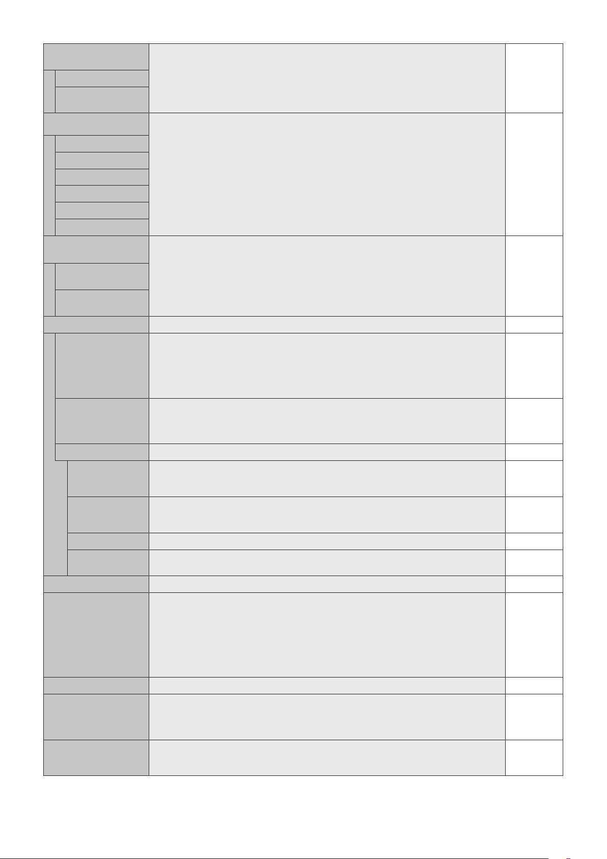
English-26
DEINTERLACE Selects the IP (Interlace to Progressive) conversion function.
Note: For DVI input “DVI-HD” needs to be enabled in the DVI mode menu.
ON
ON Converts interlaced signals to progressive. This is the default setting.
OFF Disables IP conversion. This setting is best suited for motion pictures, but increases the risk of
image retention.
COLOR SYSTEM
VIDEO, S-VIDEO inputs only
The selected Color System depends on the video format of the input signal. AUTO
AUTO Automatically chooses Color System setting based on input signal.
NTSC
PAL
SECAM
4.43 NTSC
PAL-60
OVER SCAN
HDMI,DVD/HD,SCART,VIDEO,S-VIDEO
inputs only
Some video formats may require different scanning modes in order to best display the image. ON
ON Imagesizeislargerthanwhatcanbedisplayed.Theimageedgewillappearcropped.
Approximately95%oftheimagewillbeshownonthescreen.
OFF Imagesizestayswithinthedisplayarea.Thewholeimageisdisplayedonthescreen.
NOTE: When you use a computer with HDMI out, please set “OFF”.
OPTION SETTING -
OPTION POWER Allow the monitor to supply power to Option board slot during power save mode or standby
mode.
NOTE: This function should be set to ON when using power save management by slot 2 type
option. If an option board slot that requires constant power supply is connected to the monitor,
RESPONSE IMPROVE is not available. In this case, please remove the option board slot from
the monitor. RESPONSE IMPROVE will be available.
OFF
AUDIO*
1
Selects sound input signal according to slot2 type option’s specifications. To activate DIGITAL,
select OPTION(D) for input signal and OPTION for AUDIO INPUT.
NOTE: DIGITAL is activated only when OPTION(D) is selected for input signal and OPTION for
AUDIO INPUT.
ANALOG
INTERNAL PC*
1
The function is available for slot 2 type PC.
OFF WARNING If OPTION POWER is OFF, a warning message appears when monitor power is turned off.
Note: Warning message does not appear when monitor power is turned off by OFF TIMER
setting or SCHEDULE setting.
OFF
AUTO OFF Monitor power is automatically “OFF” when connected PC is OFF or the monitor is in power save
mode.
Note: Monitor power is not automatically “ON” when connected PC is ON.
OFF
START UP PC When ON is selected, connected PC start-up. NO
FORCE QUIT When ON is selected, it performs force-quit PC.
Please use this function only when the operating system cannot be shut down manually.
NO
120Hz(not adjustable) -
RESPONSE IMPROVE Response Improve may reduce blurring that occurs in some moving images when it is set to
“MODE 1” or “MODE 2”.
NOTE: If RESPONSE IMPROVE is set to “MODE 1” or “MODE 2”, PIP function is not available.
When changing the setting, power supply to the option board slot will be cut down temporarily
even if OPTION POWER is ON.
If an option board slot that requires constant power supply is connected to the monitor,
RESPONSE IMPROVE is not available. In this case, please remove the option board slot from
the monitor. RESPONSE IMPROVE will be available.
MODE 1
TOUCH PANEL (not adjustable) -
RESET Resets the following settings within the ADVANCED OPTION menu back to factory setting:
INPUTDETECT(exceptthepriorityofinputsignals),INPUTCHANGE,TERMINALSETTING,
DEINTERLACE, COLOR SYSTEM, OVER SCAN, AUDIO in OPTION SETTING, START UP PC
in OPTION SETTING and FORCE QUIT in OPTION SETTING.
-
FACTORY RESET All items are returned to factory shipment state.
NOTE: You can reset all items in all daisy chain displays. Please be careful to avoid resetting all
items inadvertently.
-
*1: This function depends on which option board you use.
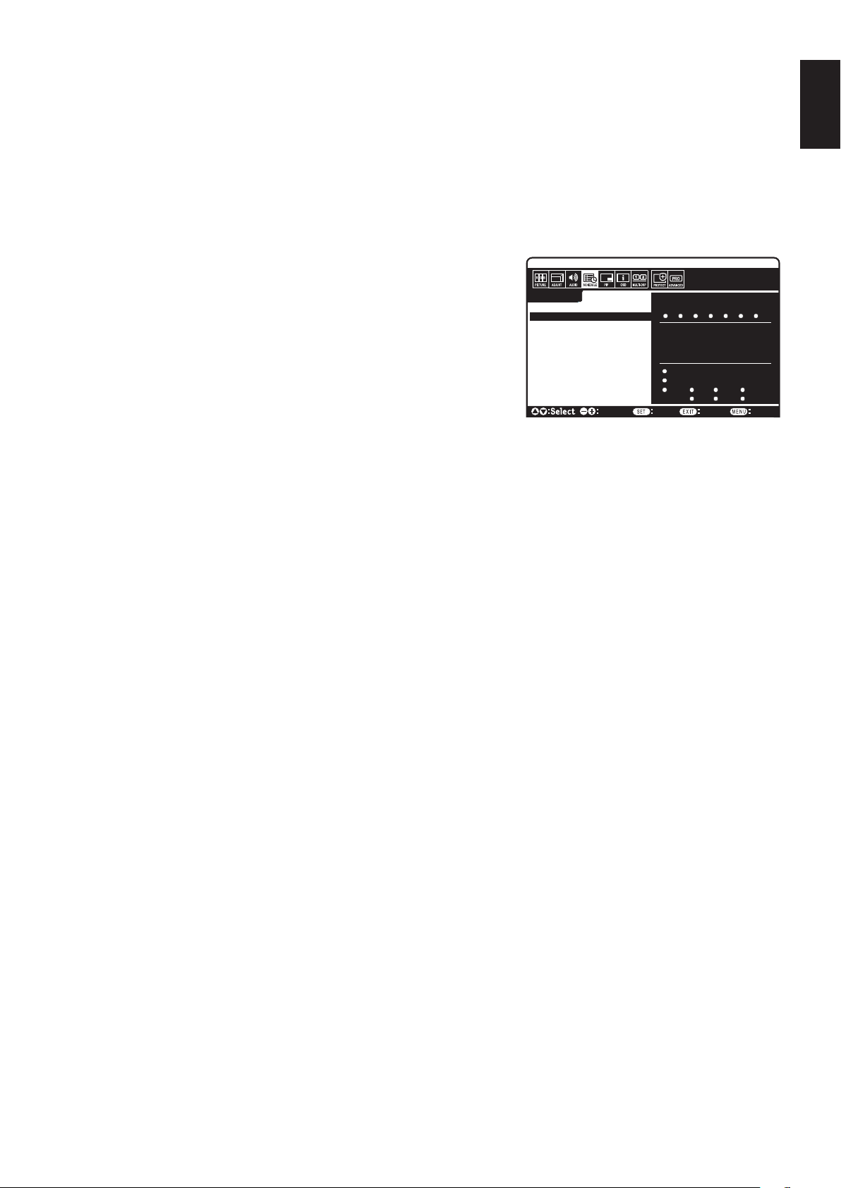
English-27
English
NOTE 1: CREATING A SCHEDULE
The schedule function allows the display to be set to power on and off at different times. Up to seven different schedules can be programmed.
To program the schedule:
1. Enter the SCHEDULE menu. Highlight SCHEDULE SETTINGS using the up and down buttons. Press the SET or the + button to enter the
Settingsmenu.Highlightthedesiredschedulenumberandpressset.Theboxnexttothenumberwillturnyellow.Theschedulecannowbe
programmed.
2. Use the down button to highlight the hours setting in the ON time slot. Use the + and - buttons to set the hour. Use the up and down buttons to
highlight the minutes setting. Use the + and - buttons to set the minutes. Set the OFF time in the same manner.
3. Use the up and down arrows to highlight INPUT. Use the + and - buttons to choose the input source. Use the up and down arrows to highlight
PIC. MODE. Use the + and - buttons to choose the picture mode.
4. Use the down button to select a day on which the schedule will be enabled. Push the set
button to enable. If the schedule is to be ran every day, choose EVERY DAY and press
theSETbutton.ThecirclenexttoEVERYDAYwillturnyellow.Ifaweeklyscheduleis
desired, choose the days of the week using the up and down buttons and pressing SET
to select. Then highlight the EVERY WEEK option and press SET.
5. After a schedule is programmed the remaining schedules can then be set. Press MENU
to leave the OSD or press EXIT to go back to the previous menu.
Note: If schedules are overlapping then the schedule with the highest number will have
priorityovertheschedulewiththelowestnumber.Forexampleschedule#7willhave
priorityoverschedule#1.
If selected input or picture mode is not available now, disable input or picture mode
is shown in red.
NOTE 2: IMAGE PERSISTENCE
PleasebeawarethatLCDTechnologymayexperienceaphenomenonknownasImagePersistence.ImagePersistenceoccurswhena
residual or “ghost” image of a previous image remains visible on the screen. Unlike CRT monitors, LCD monitors’ image persistence is not
permanent, but constant images being displayed for a long period of time should be avoided.
Toalleviateimagepersistence,turnoffthemonitorforaslongasthepreviousimagewasdisplayed.Forexample,ifanimagewasonthe
monitor for one hour and a residual image remains, the monitor should be turned off for one hour to erase the image.
As with all personal display devices, NEC DISPLAY SOLUTIONS recommends displaying moving images and using a moving screen saver at
regular intervals whenever the screen is idle or turning off the monitor when not in use.
Please set “SCREEN SAVER”, “DATE &TIME” and “SCHEDULE SETTINGS” functions to further reduce the risk of Image persistence.
For long life use as Public Display
Image Sticking of LCD Panel
When an LCD panel is operated continuously for long hours, a trace of electric charge remains near the electrode inside LCD, and residual or
“ghost” image of previous image may be observed. (Image Persistence)
ImagePersistenceisnotpermanent,butwhenxedimageisdisplayedforlongperiod,ionicimpuritiesinsideLCDareaccumulatedalongthe
displayed image, and may be permanent. (Image Sticking)
Recommendations
To prevent Image Sticking, and for longer life usage of LCD, the following are recommended.
1.Fixedimageshouldnotbedisplayedforlongperiod.Changexedimagesaftershortintervals.
2. When not in use, please turn off the monitor by remote control, or use Power Management or use Schedule Functions.
3. Lower environmental temperatures prolong the lifespan of the monitor.
When Protective surface (glass, acrylic) is installed over the LCD surface, the LCD surface is located in an enclosed space, the monitor are
stacked,utilizethetemperaturesensorsinsidemonitor.
To reduce the environmental temperature, use the Cooling Fan, Screen Saver and Low Brightness.
4. Please use “Screen Saver Mode” of monitor.
SCHEDULE:
ON: – – : – –
OFF: – – : – –
– – – –
INPUT:
PIC. MODE: – – – –
DVI
(THU) JUN.18.2009 15:38
SETTINGS:
OFF TIMER
SCHEDULE SETTINGS
SCHEDULE LIST
DATE & TIME
RESET
MON TUE WED THU
SAT SUNFRI
1
2 3 4 5 6 7
Choose Mark
Return Close
EVERY DAY
EVERY WEEK
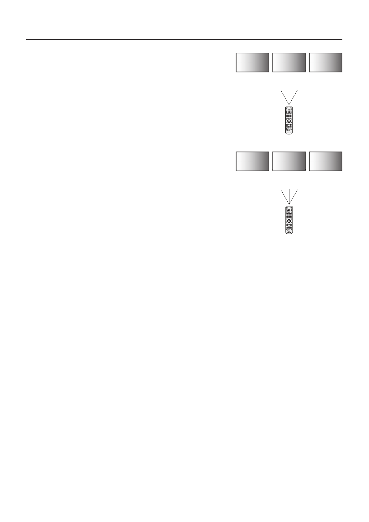
English-28
REMOTE CONTROL ID FUNCTION
REMOTE CONTROL ID
The remote control can be used to control up to 100 individual MultiSync monitors using
what is called the REMOTE CONTROL ID mode. The REMOTE CONTROL ID mode
works in conjunction with the Monitor ID, allowing control of up to 100 individual MultiSync
monitors.Forexample:iftherearemanymonitorsbeingusedinthesamearea,aremote
control in normal mode would send signals to every monitor at the same time (see
Figure 1). Using the remote in REMOTE CONTROL ID mode will only operate one specific
monitor within the group (see Figure 2).
TO SET REMOTE CONTROL ID
While holding down the REMOTE ID SET button on the remote control, use the KEYPAD to
input the Monitor ID (1-100) of the display to be controlled via remote. The remote can then
be used to operate the monitor having that specific Monitor ID number.
When 0 is selected or when the remote control is in normal mode, all monitors will be
operated.
TO SET/RESET REMOTE CONTROL MODE
ID Mode - To enter ID Mode press the REMOTE ID SET button and hold down for
2 seconds.
Normal Mode - To return to Normal Mode press the REMOTE ID CLEAR button and hold
down for 2 seconds.
In order for this feature to work properly, the display must be assigned a Monitor ID number.
The Monitor ID number can be assigned under the MULTI DISPLAY menu in the OSD
(See page 23).
Point the remote control towards the remote sensor of the desired monitor and press the
REMOTE ID SET button. The MONITOR ID number is shown on the display when your
remote control is in ID mode.
Use the remote control to operate a monitor that has a specific MONITOR ID number assigned to it.
1. Set the MONITOR ID number for the display (See page 23). The MONITOR ID number can range from 1-100.
This MONITOR ID number allows the remote control to operate this specific monitor without affecting other monitors.
2. On the remote control, press and hold down the REMOTE ID SET button while using the keypad to input the REMOTE CONTROL ID number
(1-100). The REMOTE ID NUMBER should match the MONITOR ID number of the display to be controlled. Choose “0” to simultaneously
control all displays in range.
3. Point the remote control towards the remote sensor of the desired monitor and press the REMOTE ID SET button.
The MONITOR ID number is shown in red on the display.
If the REMOTE CONTROLID is “0”, then all displays in range will show their respective MONITOR ID number in red.
If the MONITOR ID number is shown in white on the display, the MONITOR ID number and the REMOTE CONTROL ID are not the same.
This LCD monitor can be controlled via personal computer or wireless remote control using an RS-232C connection.
MONITOR ID and IR CONTROL
Using one PC or one infrared wireless remote control, up to 100 individual LCD monitors can be controlled through a daisy chain via RS-232C
connection.
1. Connect PC and LCD monitors.
Connect a PC’s RS-232C control output to the LCD monitor RS-232C input. You can then connect the RS-232C output from the LCD monitor
to another LCD monitor RS-232C input. Up to 100 monitors can be connected using RS-232C.
2. Set Monitor ID and IR Control mode.
For proper operation, the Monitor ID should be set in the OSD menu of each monitor that is in the chain. The Monitor ID can be set under the
“MULTI DISPLAY” menu in the OSD. The Monitor ID number can be set within a range from 1 to 100. No two monitors should share the same
Monitor ID number. It is recommended to number each monitor in a daisy chain sequentially from 1. The first monitor in the daisy chain is
designated as the primary monitor. Subsequent monitors with the chain are secondary monitors.
In the “ADVANCED OPTION” menu on the first monitor in the RS-232C daisy chain set the “IR CONTROL” to “PRIMARY”.
Set the “IR CONTROL” to “SECONDARY” on all other monitors.
Remote Control Function
Monitor ID:1 Monitor ID:2 Monitor ID:3
Monitor ID:1 Monitor ID:2 Monitor ID:3
Remote does
not work
Remote does
not work
Remote works
Remote works Remote works Remote works
Figure 1
Remote in
Normal mode or
the REMOTE ID
is set to 0
Figure 2
Remote set up
to use REMOTE
ID:3

English-29
English
3. Press the “DISPLAY” button on the remote control while aiming at the “PRIMARY” monitor. The Information OSD will be shown at
top left side of the screen.
Monitor ID: Displays the ID number of the current monitor within the daisy chain.
Target ID: Displays the ID number of the monitor that to be controlled via daisy chain from the current monitor.
Press the “+” or “-” buttons to change the “Target ID” to show the ID number of the monitor to be controlled. To control the entire daisy chained
monitors simultaneously, select “ALL” as the “Target ID.”
4. Use the wireless remote control to control the “SECONDARY” monitor while aiming at the “PRIMARY” monitor.
The “MENU OSD” will appear on the selected target monitor.
NOTE: If the “ID No.” mode select OSD is showing, press the “DISPLAY” button on the remote control while pointing at the “PRIMARY”
monitor to clear this OSD.
HINT: If you lost control due to the incorrect setting of “IR CONTROL”, pressing the “DISPLAY” button on the remote control for 5 or
more seconds will reset the “IR CONTROL” menu to “NORMAL” function.
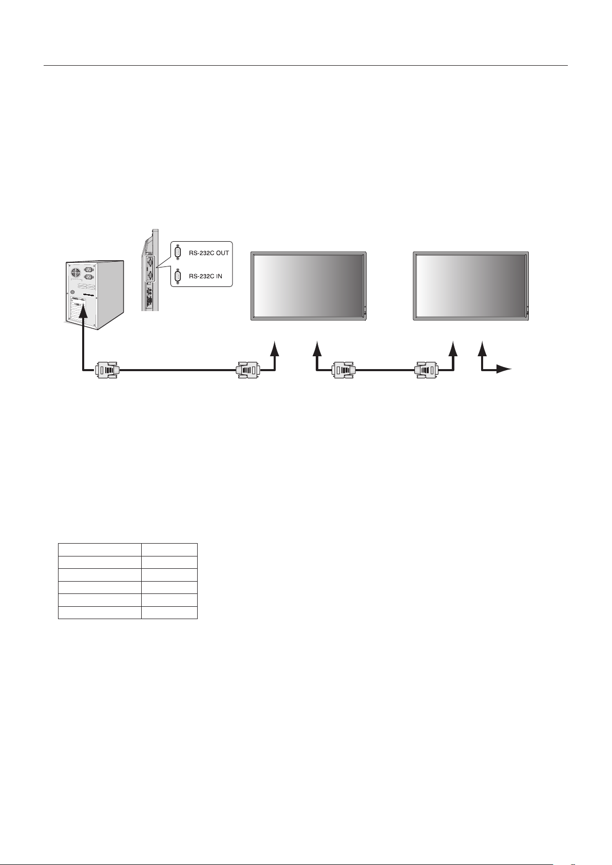
English-30
This LCD monitor can be controlled by connecting a personal computer with a RS-232C terminal.
NOTE: When you use this function, EXTERNAL CONTROL should be “RS-232C” (See page 24).
Functions that can be controlled by a personal computer are:
•PowerONorOFF.
•Switchingbetweeninputsignals.
•SoundMuteONorOFF.
Connection
LCD Monitor + computer
RS-232C Cable
Computer (Out)
RS-232C Cable
RS-232C (OUT)
MultiSync
RS-232C (IN)RS-232C (OUT)RS-232C (IN)
MultiSync MultiSync
NOTE: If your computer is equipped only with a 25-pin serial port connector, a 25-pin serial port adapter is required.
Contact your dealer for details.
Check the “ID=ALL REPLY” setting in “EXTERNAL CONTROL”.
* In order to function, the RS-232C OUT terminal can only be connected to another monitor of the same model.
Do not connect to other types of equipment.
To control monitor or multiple monitors that are daisy-chained together, please use the control command. Instructions for the
controlcommandcanbefoundontheCDincludedwiththedisplay.Theleiscalled“External_control.pdf”.
Multiple monitors that are daisy-chained have a limit to the conectable monitor.
1) Interface
PROTOCOL RS-232C
BAUD RATE 9600 [bps]
DATA LENGTH 8 [bits]
PARITY BIT NONE
STOP BIT 1 [bit]
FLOW CONTROL NONE
This LCD monitor uses RXD, TXD and GND lines for RS-232C control.
The reverse type cable (null modem cable) (not include) should be used for RS-232C control.
Controlling the LCD monitor via RS-232C Remote Control
English-31
English
2) Control command diagram
Forothercommands,pleasesee“External_Control.pdf”leontheCD-ROM.
Function (Monitor ID = 1) Code Data
Power ON 01 30 41 30 41 30 43 02 43 32 30 33 44 36 30 30 30 31 03 73 0d
Power OFF 01 30 41 30 41 30 43 02 43 32 30 33 44 36 30 30 30 34 03 76 0d
Input Source Select DisplayPort 01 30 41 30 45 30 41 02 30 30 36 30 30 30 30 46 03 04 0d
Input Source Select DVI 01 30 41 30 45 30 41 02 30 30 36 30 30 30 30 33 03 71 0d
Input Source Select VGA 01 30 41 30 45 30 41 02 30 30 36 30 30 30 30 31 03 73 0d
Input Source Select HDMI 01 30 41 30 45 30 41 02 30 30 36 30 30 30 31 31 03 72 0d
InputSourceSelectDVD/HD01 30 41 30 45 30 41 02 30 30 36 30 30 30 30 43 03 01 0d
Input Source Select VIDEO 01 30 41 30 45 30 41 02 30 30 36 30 30 30 30 35 03 77 0d
Input Source Select S-VIDEO 01 30 41 30 45 30 41 02 30 30 36 30 30 30 30 37 03 75 0d
Input Source Select OPTION 01 30 41 30 45 30 41 02 30 30 36 30 30 30 30 44 03 06 0d
Sound Mute ON 01 30 41 30 45 30 41 02 30 30 38 44 30 30 30 31 03 09 0d
Sound Mute OFF 01 30 41 30 45 30 41 02 30 30 38 44 30 30 30 32 03 0a 0d
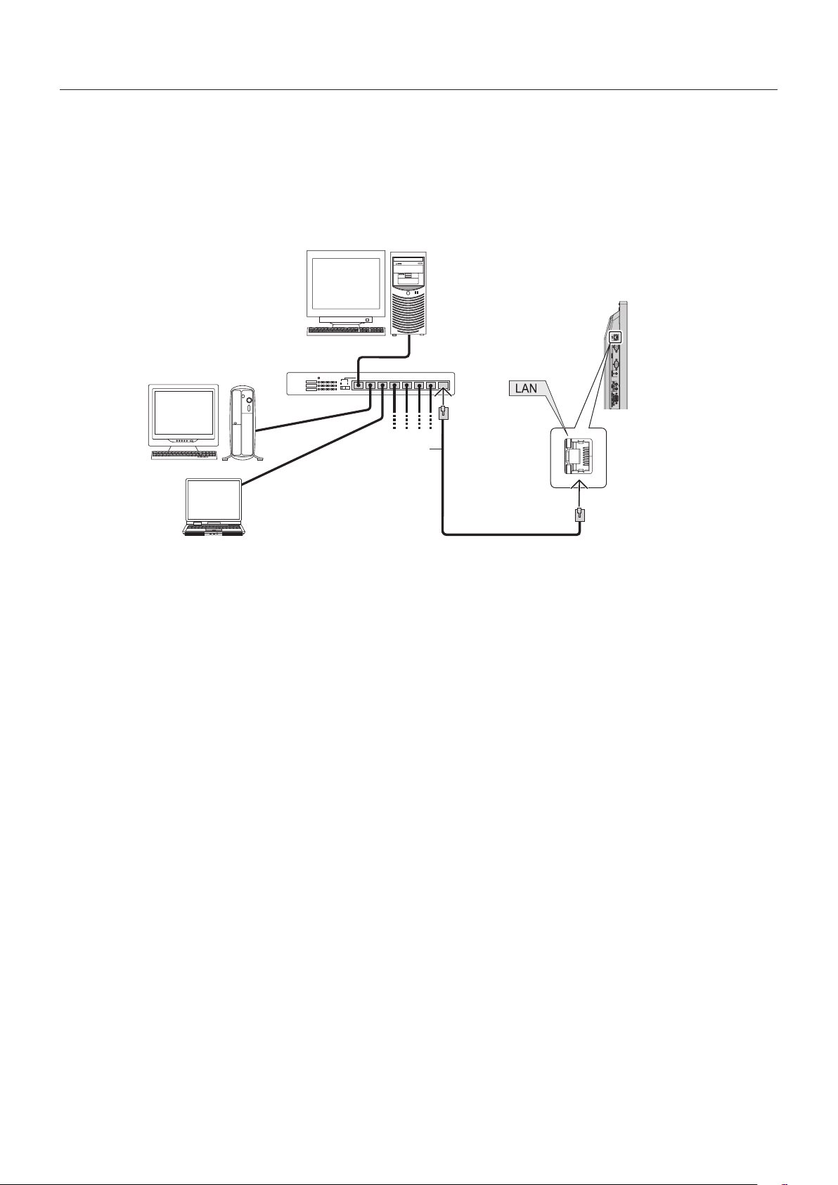
English-32
Connecting to a Network
Using a LAN cable allows you to specify the Network Settings and the Alert Mail Settings by using an HTTP server function.
NOTE: When you use this function, EXTERNAL CONTROL should be “LAN” (See page 24).
To use a LAN connection, you are required to assign an IP address.
Example of LAN connection:
Server
Hub
NOTE: Use a category 5 or higher LAN cable.
LAN cable
(not supplied)
Network Setting by Using an HTTP Browser
Overview
Connecting the monitor to a network allows for monitor control from a computer via the network.
Toperformthemonitorcontrolfromawebbrowser,youmusthaveanexclusiveapplicationinstalledonyourcomputer.
The IP address and subnet mask of the monitor can be set on the Network Setting screen of the web browser by using an HTTP
serverfunction.Pleasebesuretouse“MicrosoftInternetExplorer6.0”orahigherversionforthewebbrowser.
(This device uses “JavaScript” and “Cookies” and the browser should be set to accept these functions. The setting method will
vary depending on the version of browser. Please refer to the help files and the other information provided in your software.)
Access is gained to the HTTP server function by starting the Web browser on the computer via the network connected to the
monitor and entering the following URL.
Network Setting
http://<theMonitor’sIPaddress>/index.html
TIP: The default IP address is “192.168.0.10”.
Theexclusiveapplicationcanbedownloadedfromourwebsite.
NOTE: If the MONITOR NETWORK SETTINGS screen does not appear in the web browser, press the Ctrl+F5 keys to
refresh your web browser (or clear the cache).
The display or button’s response can be slowed down or operation may not be accepted depending the settings of
your network. Should this happen, consult your network administrator.
The LCD monitor may not respond if its buttons are repeatedly pressed in rapid intervals. Should this happen, wait a
moment and repeat. If you still can’t get a response, turn the monitor off and then back on.
Controlling the LCD monitor via LAN Control
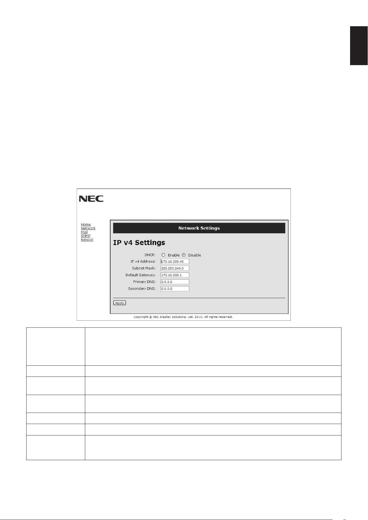
English-33
English
Preparation Before Use
Connect the monitor to a commercially available LAN cable before engaging in browser operations.
Operationwithabrowserthatusesaproxyservermaynotbepossibledependingonthetypeofproxyserverandthesetting
method.Althoughthetypeofproxyserverwillbeafactor,itispossiblethatitemsthathaveactuallybeensetwillnotbe
displayeddependingontheeffectivenessofthecache,andthecontentssetfromthebrowsermaynotbereectedinoperation.
Itisrecommendedthataproxyservernotbeusedunlessitisunavailable.
Handling of the Address for Operation via a Browser
The host name can be used under the following cases:
If the host name corresponding to the IP address of the monitor has been registered to the domain name server (DNS) by the
network administrator, you can then access the network settings of the display via that registered host name using a compatible
browser.
If the host name corresponding to the IP address of the monitor has been configured in the “HOSTS” file of the computer being
used, you can then access the network settings of the display via that host name using a compatible browser.
Example1: Whenthehostnameofthemonitorhasbeensetto“pd.nec.co.jp”,accessisgainedtothenetworksettingby
specifying http://pd.nec.co.jp/index.html for the address or the entry column of the URL.
Example2: WhentheIPaddressofthemonitoris“192.168.73.1”,accessisgainedtothemailalertsettingsbyspecifying
http://192.168.73.1/index.html for the address or the entry column of the URL.
Network Settings
http://<theMonitor’sIPaddress>/index.html
DHCP Enabling this option automatically assigns an IP address to the monitor from your DHCP server.
Disabling this option allows you to register the IP address or subnet mask number obtained from your
network administrator.
NOTE: Consult your network administrator for the IP address when [ENABLE] is selected for
[DHCP].
IP v4 Address Set your IP address of the network connected to the monitor when [DISABLE] is selected for [DHCP].
Subnet Mask Set your subnet mask number of the network connected to the monitor when [DISABLE] is selected
for [DHCP].
Default Gateway Set your default gateway of the network connected to the monitor when [DISABLE] is selected for
[DHCP].
Primary DNS Set your primary DNS settings of the network connected to the monitor.
Secondary DNS Set your secondary DNS settings of the network connected to the monitor.
Apply Reectyoursettings.
NOTE:Makesuretoexecute“thereboot”fromthe“rebootscreen”ortoturnthemonitoroffand
then back on to enable the changing, after clicking [Apply].
NOTE: The following settings will reset back to the factory setting when “LAN reset” is selected by an EXTERNAL CONTROL
of OSD:
[DHCP]: DISABLE, [IP v4 Address]: 192.168.0.10, [Subnet Mask]: 255.255.255.0, [Default Gateway]: 192.168.0.1 but
[Primary DNS] and [Secondary DNS] are not changed.
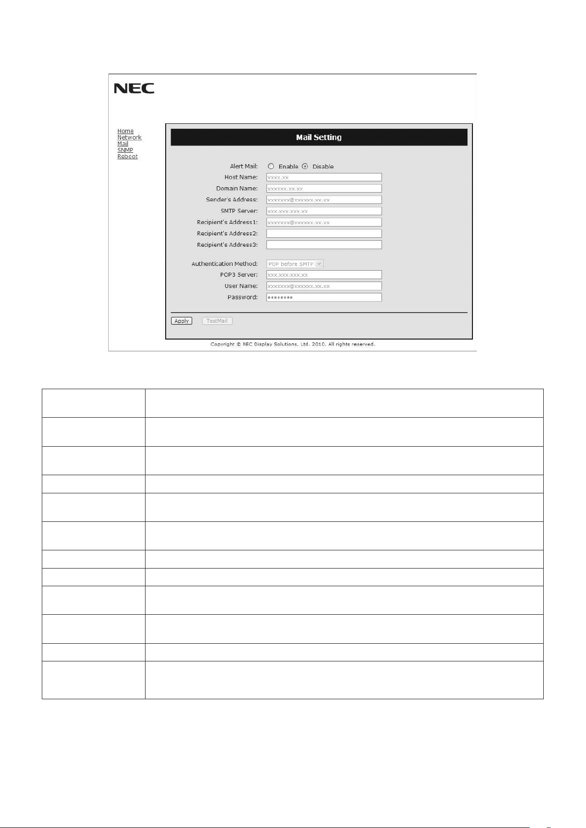
English-34
Alert Mail Setting
http://<theMonitor’sIPaddress>/lancong.html
This option notifies your computer of an error message via e-mail when using wired LAN. An error message notification will be
sent when an error occurs in the monitor.
Alert Mail Checking [ENABLE] will turn on the Alert Mail feature.
Checking [DISABLE] will turn off the Alert Mail feature.
Host Name Type in the hostname of the network connected to the monitor.
Up to 60 alphanumeric characters can be used.
Domain Name Type in the domain name of the network connected to the monitor.
Up to 60 alphanumeric characters can be used.
Sender’s Address Type in the senders address. Up to 60 alphanumeric and symbols characters can be used.
SMTP Server Type in the SMTP server name to be connected to the monitor.
Up to 60 alphanumeric characters can be used.
Recipient’s Address
1 to 3
Type in your recipient’s address. Up to 60 alphanumeric and symbols characters can be used.
Authentication Method This selects the authentication method of the e-mail transmission.
POP3 Server This specifies the address of the POP3 server that is used in the authentication of the e-mail.
User Name This sets the user name for logging into the authentication server when authentication is required
for the e-mail transmission. Up to 60 alphanumeric characters can be used.
Password This sets the password for logging into the authentication server when authentication is required for
the e-mail transmission. Up to 60 alphanumeric characters can be used.
TestMail Click this button to send a test mail to check if your settings are correct.
Apply Clickthisbuttontoreecttheabovesettings.
NOTE:Makesuretoexecute“thereboot”fromthe“rebootscreen”ortoturnthemonitoroffand
then back on to enable the changing, after clicking [Apply].
NOTE: •Ifyouexecuteatest,youmaynotreceiveanAlertmail.
Should this happen, check if the network settings are correct.
•Ifyouenteredanincorrectaddressinatest,youmaynotreceiveanAlertmail.
Should this happen, check if the Recipient’s Address is correct.
TIP: ForControlcommanddiagram,pleaseseele“External_Control.pdf”ontheCD-ROM.
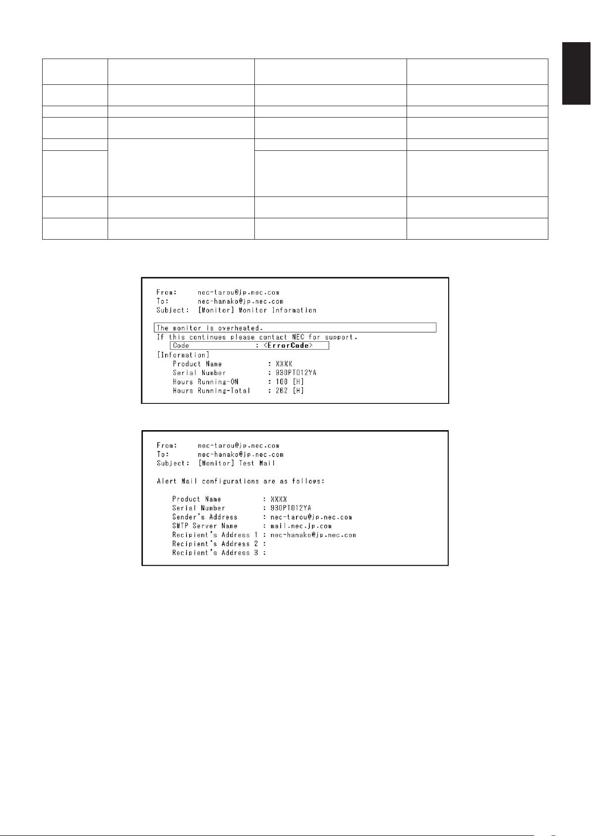
English-35
English
Alert error message list
Error number
* ErrorCode
Alert mail Message Explanation Measure
70h ~ 7Fh
The monitor’s power supply is not
functioning normally.
Standby power Abnormal Please contact your supplier.
80h ~ Fh The cooling fan has stopped. Cooling fan Abnormal Please contact your supplier.
90h ~ 9Fh
The monitor’s back light unit is not
functioning normally.
Backlight abnormal Please contact your supplier.
A0h ~ AFh The monitor is overheated. Temperature Abnormal Please contact your supplier.
A2h
SENSOR reached at the temperature
that the user had specified.
*condition: DISPLAY PROTECTION-FAN
CONTROL-COOLING FAN = AUTO
Reconfirm the setting condition from
OSD (DISPLAY PROTECTION-FAN
CONTROL) or please contact your
supplier.
B0h ~ BFh
The monitor doesn’t have the input
signal.
No signal Please check “No picture” in
“Troubleshooting”.
C0h ~ CFh
The monitor caused the problem of the
abnormal of option board.
Option board abnormal Please contact your supplier.
Sample:ThefollowingexamplesarecontentofAlertMailthatinformsthetemperatureanomalyofmonitor.
Sample:Thefollowingexamplesarecontentoftestmailbybrowser.
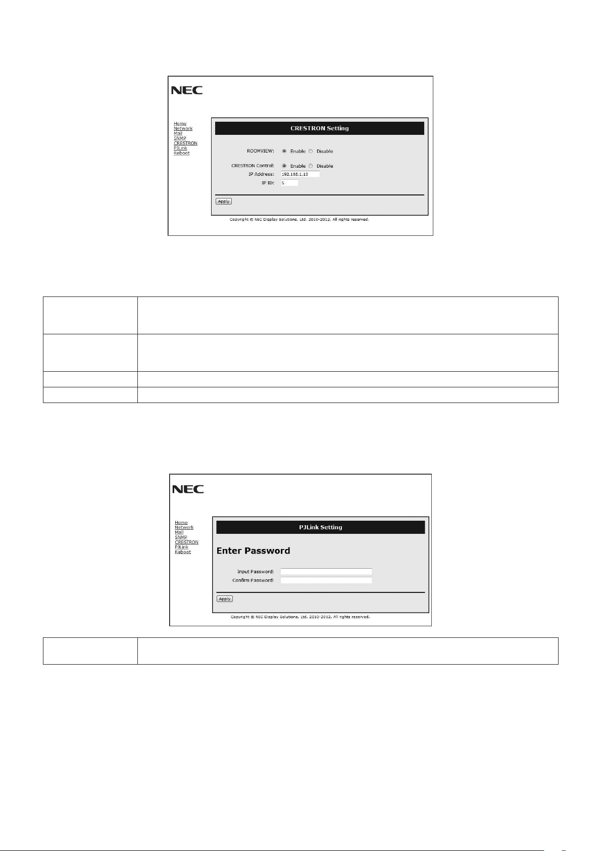
English-36
CRESTRON Setting
Click “CRESTRON” on the left side of HOME.
CRESTRON ROOMVIEW compatibility
The monitor supports CRESTRON ROOMVIEW, allowing multiple devices connected in the network to be managed and
controlled from a computer or a controller.
Formoreinformation,visithttp://www.crestron.com
ROOMVIEW ROOMVIEW for managing from the computer.
ON: Enables ROOMVIEW.
OFF: Disables ROOMVIEW.
CRESTRON
CONTROL
CRESTRON CONTROL for managing from the controller.
ON: Enables CRESTRON CONTROL.
OFF: Disables CRESTRON CONTROL.
IP ADDRESS Set your IP address of CRESTRON SERVER.
IP ID Set your IP ID of CRESTRON SERVER.
TIP: The CRESTRON settings are required only for use with CRESTRON ROOMVIEW.
Formoreinformation,visithttp://www.crestron.com
PJLink Setting
Click “PJLink” on the left side of HOME.
PASSWORD Set a password for PJLink*. A password must be 32 characters or less. Do not forget your password.
However, if you forget your password, consult with your dealer.
*What is PJLink?
PJLinkisastandardizationofprotocolusedforcontrollingdevicesofdifferentmanufacturers.Thisstandardprotocolis
established by Japan Business Machine and Information System Industries Association (JBMIA) in 2005.
The device supports all the commands of PJLink Class 1.
Setting of PJLink will not be affected even when [RESET] is done from the menu.

English-37
English
Reduced Footprint: Provides the ideal solution for environments with superior image quality.
Color Control Systems: Allowyoutoadjustthecolorsonyourscreenandcustomizethecoloraccuracyofyourmonitortoa
variety of standards.
Natural Color Matrix:CombinesSix-axiscolorcontrolandthesRGBstandard.Six-axiscolorcontrolpermitscoloradjustments
viasixaxes(R,G,B,C,MandY)ratherthanthroughthethreeaxes(R,GandB)previouslyavailable.ThesRGBstandard
providesthemonitorwithauniformcolorprole.Thisensuresthatthecolorsdisplayedonthemonitorareexactlythesameas
on the color printout (with sRGB supporting operating system and sRGB printer). This allows you to adjust the colors on your
screen and customise the color accuracy of your monitor to a variety of standards.
sRGB Color Control: Anewoptimizedcolormanagementstandardwhichallowsforcolormatchingoncomputerdisplaysand
other peripherals. The sRGB standard, which is based on a calibrated color space, allows for optimal color representation and
backward compatibility with other common color standards.
OSD (On-Screen-Display) Controls: Allow you to quickly and easily adjust all elements of your screen image via simple to use
on-screen menus.
Plug and Play: The Microsoft
®
solution with the Windows
®
operating system facilitates setup and installation by allowing
the monitor to send its capabilities(suchasscreensizeandresolutionssupported)directlytoyourcomputer,automatically
optimizingdisplayperformance.
IPM (Intelligent Power Manager) System: Provides innovative power-saving methods that allow the monitor to shift to a
lower power consumption level when on but not in use, saving two-thirds of your monitor energy costs, reducing emissions and
lowering the air conditioning costs of the workplace.
FullScan Capability: Allowsyoutousetheentirescreenareainmostresolutions,signicantlyexpandingimagesize.
VESA Standard (FDMIv1) Mounting Interface: Allows you to connect your LCD monitor to any VESA standard (FDMIv1) third
partymountingarmorbracket.NECrecommendsusingmountinginterfacethatcomplywithTÜV-GSand/orUL1678standard
in North America.
DVI-D: The digital-only subset of DVI ratified by the Digital Display Working Group (DDWG) for digital connections between
computers and displays. As a digital-only connector, analog support is not provided for a DVI-D connector. As a DVI-based
digital only connection, only a simple adapter is necessary for compatibility between DVI-D and other DVI-based digital
connectors such as DFP and P&D. The DVI interface of this display supports HDCP.
TILE MATRIX, TILE COMP: Showsoneimageovermultiplescreenswithaccuracywhilecompensatingforbezelwidth.
ZOOM: Expands/reducesimagesizeforhorizontalandverticaldirection.
RS-232C daisy chain: You can control the multiple monitors by control or wireless remote control.
Self-diagnosis: If an internal error should occur, a failure state will be indicated.
HDCP (High-bandwidth Digital Content Protection): HDCP is a system for preventing illegal copying of video data sent
over a digital signal. If you are unable to view material via the digital input, this does not necessarily mean the display is not
functioning properly. With the implementation of HDCP, there may be cases in which certain content is protected with HDCP and
mightnotbedisplayedduetothedecision/intentionoftheHDCPcommunity(DigitalContentProtection,LLC).
Option board slot: You can use an option board. Please contact your supplier for detailed information.
Features

English-38
No picture
•Thesignalcableshouldbecompletelyconnectedtothedisplay
card/computer.
•Thedisplaycardshouldbecompletelyseatedinitsslot.
•
Check the main Power Switch, it should be in the ON position.
•PowerSwitchandcomputerpowerswitchshouldbeintheON
position.
•
Check to make sure that a supported mode has been selected
on the display card or system being used. (Please consult display
card or system manual to change graphics mode.)
•Checkthemonitorandyourdisplaycardwithrespectto
compatibility and recommended settings.
•Checkthesignalcableconnectorforbentorpushed-inpins.
•IfAUTOSTANDBYisON,themonitorautomaticallygoesinto
OFF mode 10 minutes after signal is lost. Press the power
button.
Power Button does not respond
•UnplugthepowercordofthemonitorfromtheACoutlettoturn
off and reset the monitor.
•
Check the main Power Switch on the rear side of the monitor.
•ChecktheDVIMODEsettingwhenDVDplayerorcomputer
equipment is connected to the DVI input.
Snowy Picture, Black Screen in DVI input
•ChecktheDVIMODEsettingwhenDVDplayerorcomputer
equipment is connected to the DVI input.
Image persistence
•PleasebeawarethatLCDTechnologymayexperiencea
phenomenon known as Image Persistence. Image Persistence
occurs when a residual or “ghost” image of a previous image
remains visible on the screen. Unlike CRT monitors, LCD
monitors’ image persistence is not permanent, but constant
images being displayed for a long period of time should be
avoided. To alleviate image persistence, turn off the monitor for
aslongasthepreviousimagewasdisplayed.Forexample,if
an image was on the monitor for one hour and a residual image
remains, the monitor should be turned off for one hour to erase
the image.
NOTE: As with all personal display devices, NEC DISPLAY
SOLUTIONS recommends displaying moving images
and using a moving screen saver at regular intervals
whenever the screen is idle or turning off the monitor
when not in use.
Image is unstable, unfocused or swimming is apparent
•Signalcableshouldbecompletelyattachedtothecomputer.
•UsetheOSDImageAdjustcontrolstofocusandadjustdisplay
by increasing or decreasing the fine adjustment.
When the display mode is changed, the OSD Image Adjust
settings may need to be re-adjusted.
•Checkthemonitorandyourdisplaycardwithrespectto
compatibility and recommended signal timings.
•Ifyourtextisgarbled,changethevideomodetonon-interlace
anduse60Hzrefreshrate.
•Theimagemaybedistortedwhenturningthepoweronor
changing the settings.
Image of component signal is greenish
•ChecktoseeiftheDVD/HDinputconnectorisselected.
LED on monitor is not lit (no green or red color can be seen)
•PowerSwitchshouldbeintheONpositionandpowercord
should be connected.
•CheckthemainPowerSwitch,itshouldbeintheONposition.
•Makecertainthecomputerisnotinapower-savingmode(touch
the keyboard or mouse).
•ChecktoseethatthepowerindicatoroptionintheOSDissetto
ON.
RED LED on monitor is blinking
•Acertainfailuremighthaveoccurred,pleasecontactyour
nearestauthorizedNECDISPLAYSOLUTIONSservicefacility.
•Ifthemonitorispoweredoffbytheinsidetemperaturebeing
higher than the normal operating temperature, a RED LED will
blinksixtimes.Poweronthedisplayagainafterconrming
the inside temperature has been reduced to normal operation
temperature.
Display image is not sized properly
•UsetheOSDImageAdjustcontrolstoincreaseordecreasethe
coarse adjustment.
•Checktomakesurethatasupportedmodehasbeenselected
on the display card or system being used.
(Please consult display card or system manual to change
graphics mode.)
Selected resolution is not displayed properly
•UseOSDDisplayModetoenterInformationmenuandconrm
that the appropriate resolution has been selected. If not, select
corresponding option.
No Sound
•Checktoseeifaudiocableisproperlyconnected.
•Checktoseeifmuteisactivated.
•Checktoseeifvolumeissetatminimum.
•Checktoseeifcomputersupportsanaudiosignalthrough
DisplayPort.
If unsure, contact the computer manufacturer.
•ChecktoseeifSURROUNDisON.
•CheckInternal/Externalspeakerswitch.
Remote Control is not available
•ChecktheRemoteControl’sbatteriesstatus.
•Checkifbatteriesareinsertedcorrectly.
•CheckiftheRemoteControlispointingatthemonitor’sremote
sensor.
•ChecktheRemoteControlModestatus.
•Theremotecontrolsystemmaynotfunctionwhendirectsunlight
or strong illumination strikes the remote control sensor of the
LCD monitor, or when there is an object in the path.
“SCHEDULE”/“OFF TIMER” function is not working properly
•The“SCHEDULE”functionwillbedisabledwhenthe“OFF
TIMER” is set.
•Ifthe“OFFTIMER”functionisenabledandthepowertothe
LCD monitor is turned off when the power supply is interrupted
unexpectedly,thenthe“OFFTIMER”willbereset.
Snowy Picture, Poor Sound in TV
•Checkantenna/cableconnection.Usenewcableifnecessary.
Interference in TV
•Checkcomponentsforshielding,moveawayfrommonitorif
necessary.
RS-232C or LAN control is not available
•CheckRS-232CorLANcableconnection.
•Check“CONTROL”settingin“EXTERNALCONTROL”.
•Checkthe“ID=ALLREPLY”settingin“EXTERNALCONTROL”.
Eitherlightverticalorhorizontalstripesmayappear,dependingonthespecicdisplaypattern.Thisisnoproductfaultordegradation.
Troubleshooting
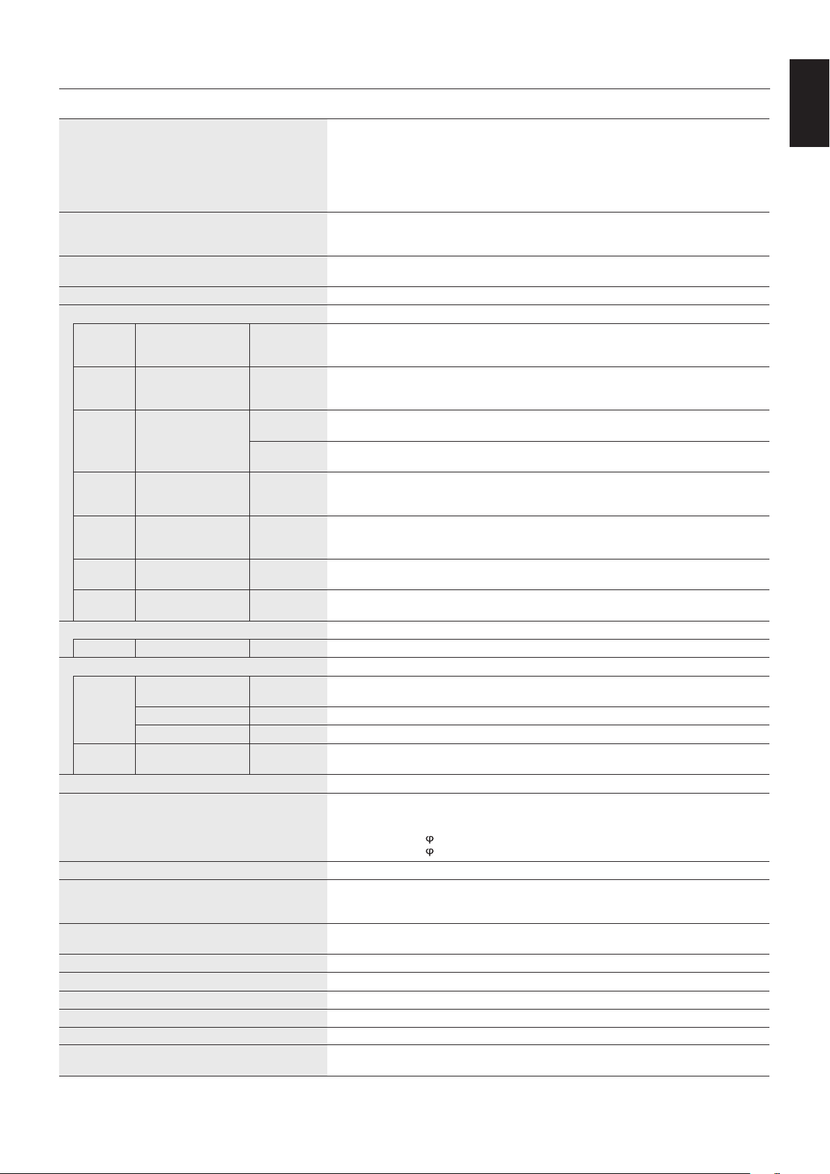
English-39
English
Specifications
Product Specifications
LCD Module
PixelPitch:
Resolution:
Color:
Brightness:
Contrast Ratio:
Viewing Angle:
31.5”/80.13cmdiagonal
0.36375 mm
1920x1080
Over 16 million colors (depending on display card used)
450cd/m
2
(Max.)@25°C
1300:1
89°(typ)@CR>10
Frequency Horizontal:
Vertical:
15.625/15.734kHz,31.5kHz-91.1kHz(AnalogInput)
31.5kHz-91.1kHz(DigitalInput)
50.0-85.0Hz
PixelClock13.5 MHz,25 MHz-165 MHz(Analog)
25 MHz-165 MHz(Digital)
ViewableSize698.4x392.9mm
Input Signal
DVI DVI-D 24pin Digital RGB DVI (HDCP1.4)
VGA60, SVGA60, XGA60, WXGA60, SXGA60, UXGA60*
1
,1920X1080(60Hz),1080p,
1080i*
1
DisplayPort DisplayPort Connector Digital RGB DisplayPort V1.1a (HDCP1.3)
VGA60, SVGA60, XGA60, WXGA60, SXGA60, UXGA60*
1
,1920x1080(60Hz),1080p,1080i,
720p@50Hz/60Hz,576p@50Hz,480p@60Hz
VGA*
2
15pin Mini D-sub Analog RGB 0.7Vp-p/75ohm
VGA60, SVGA60, XGA60, WXGA60, SXGA60, UXGA60*
1
,1920X1080(60Hz)
Sync Separate:TTLlevel(Pos./Neg.)
Composite sync on Green Video: 0.3 Vp-p Neg.
HDMI HDMI Connector Digital YUV
Digital RGB
HDMI (HDCP1.4)
VGA60, SVGA60, XGA60, WXGA60, SXGA60, UXGA60*
1
,1920x1080(60Hz),1080p,1080i,
720p@50Hz/60Hz,576p@50Hz,480p@60Hz,576i@50Hz,480i@60Hz
DVD/HD*
2
15pin Mini D-sub Component Y:1.0Vp-p/75ohm,Cb/Cr(Pb/Pr):0.7Vp-p/75ohm
HDTV/DVD:1080p,1080i,720p@50Hz/60Hz,576p@50Hz,480p@60Hz,576i@50Hz,
480i@60Hz
VIDEO*
2
15pin Mini D-sub Composite 1.0Vp-p/75ohm
NTSC/PAL/SECAM/4.43NTSC/PAL60
S-VIDEO*
2
15pin Mini D-sub S-VIDEO Y:1.0Vp-p/75ohmC:0.286Vp-p/75ohm(NTSC),0.3Vp-p/75ohm(PAL/SECAM)
NTSC/PAL/SECAM/4.43NTSC/PAL60
Output Signal
DVI DVI-D 24pin Digital RGB DVI (HDCP1.4)
AUDIO
AUDIO
Input
STEREO Mini Jack Analog Audio StereoL/R0.5Vrms
HDMI Connector Digital Audio PCM32,44.1,48KHz(16/20/24bit)
DisplayPort Connector Digital Audio PCM32,44.1,48KHz(16/20/24bit)
AUDIO
Output
STEREO Mini Jack Analog Audio StereoL/R0.5Vrms
Speaker Output Internal Speaker 8 W
Control RS-232C In:
RS-232C Out:
LAN:
Remote IN:
Remote OUT:
9 Pin D-sub
9 Pin D-sub (with daisy chain)
RJ-4510/100BASE-T
Stereo Mini jack 3.5
Stereo Mini jack 3.5
Power Supply 1.6-0.65A@100-240VAC,50/60Hz
Operational Environment Temperature:
Humidity:
Altitude:
0-40°C/32-104°F
20-80%(withoutcondensation)
0 - 3000 m (Brightness may decrease with altitude)
Storage Environment Temperature:
Humidity:
-20-60°C/-4-140°F
10-90%(withoutcondensation)/90%-3.5%x(Temp-40°C)regardingover40°C
Dimension 750.0(W)x444.5(H)x60.8(D)mm/29.5(W)x17.5(H)x2.4(D)inches
Weight 9.5 kg (20.9 lbs)
VESA compatible mounting interface 200mmx200mm(M6,4Holes)
Power Management VESA DPM
Power supply for Slot 2 type OPTION 16V/3.6A
Accessories Setupmanual,PowerCord,VideoSignalcable,RemoteControl,AABatteryx2,CD-ROM,
Clamp x 1, Screw x 1,Wallmountadapterx4,Wallmountadapterscrewx4
NOTE: Technical specifications are subject to change without notice. *1: Compressed image.
*2: Common terminal.
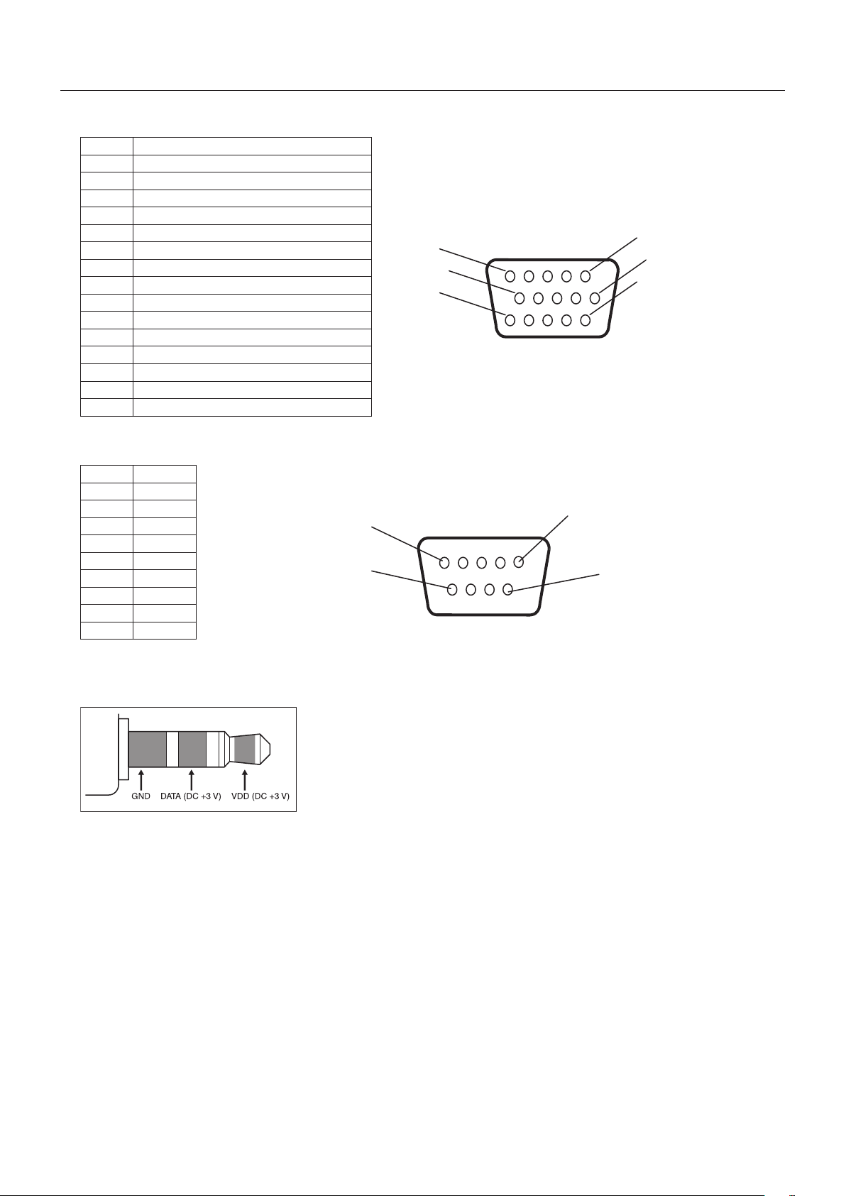
English-40
1)Analogmultiinput(MiniDsub15p):VGA,DVD/HD,SCART,VIDEO,S-VIDEO
Pin No Name
1 Red,DVD/HD_Pr,S-VIDEO_C
2 Green,DVD/HD_Y,S-VIDEO_Y,VIDEO
3 Blue,DVD/HD_Pb
4 GND
5 DDC-GND
6 Red-GND
7 Green-GND
8 Blue-GND
9 +5V (DDC)
10
SYNC-GND
11
SCART-SYNC
12
DDC-SDA
13
H-SYNC
14
V-SYNC
15
DDC-SCL
5
10
15
1
6
11
Mini D-SUB 15P
2)RS-232Cinput/output
1
6
5
9
D-SUB 9P
Pin No Name
1 NC
2 RXD
3 TXD
4 NC
5 GND
6 NC
7 NC
8 NC
9 NC
This LCD monitor uses RXD, TXD and GND lines for RS-232C control.
3) REMOTE IN
Pin Assignment
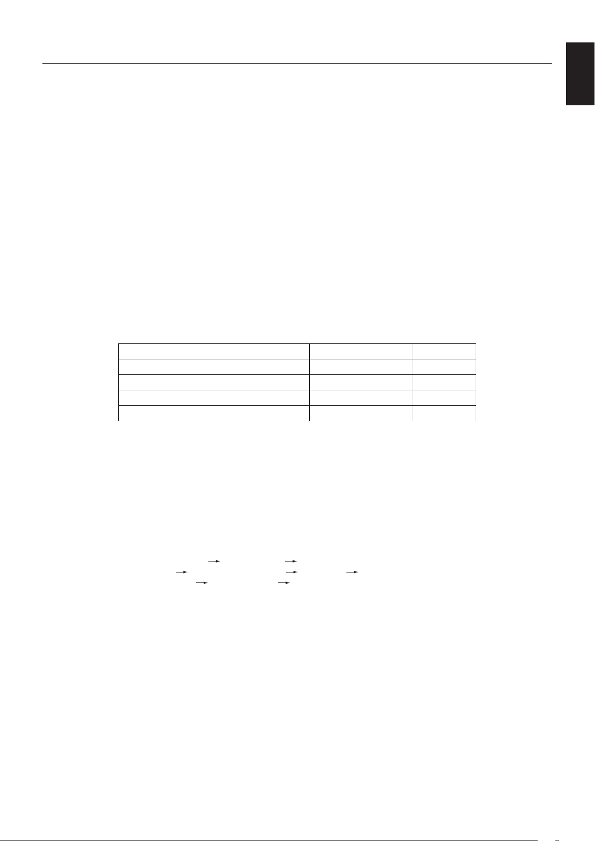
English-41
English
NEC DISPLAY SOLUTIONS is strongly committed to environmental protection and sees recycling as one of the company’s top
prioritiesintryingtominimizetheburdenplacedontheenvironment.Weareengagedindevelopingenvironmentally-friendly
products, and always strive to help define and comply with the latest independent standards from agencies such as ISO
(InternationalOrganisationforStandardization)andTCO(SwedishTradesUnion).
Disposing of your old NEC product
The aim of recycling is to gain an environmental benefit by means of re-use, upgrading, reconditioning or reclamation of
material. Dedicated recycling sites ensure that environmentally harmful components are properly handled and securely
disposed. To ensure the best recycling of our products, NEC DISPLAY SOLUTIONS offers a variety of recycling procedures
and gives advice on how to handle the product in an environmentally sensitive way, once it has reached the end of its life.
All required information concerning the disposal of the product and country-specific information on recycling facilities can be
found on our following websites:
https://www.nec-display-solutions.com/p/greenvision/en/greenvision.xhtml (in Europe),
https://www.nec-display.com (in Japan) or
https://www.necdisplay.com (in USA).
Energy Saving
This monitor features an advanced energy saving capability. When a Display Power Management signal is sent to the monitor,
the Energy Saving mode is activated. The monitor enters a single Energy Saving mode.
Mode Power consumption LED colour
Normal Operation*
1,
*
3
Approx.48WGreen
Energy Saving Mode*
1,
*
2
(POWER SAVE) Less than 1 W Amber
Energy Saving Mode*
1
(AUTO STANDBY) Less than 0.5 W Red
Power Off Less than 0.5 W Red
*1: without any option, with factory settings.
*2: VGA input only.
*3: Depends on destination.
For additional information visit:
https://www.necdisplay.com/ (in USA)
https://www.nec-display-solutions.com/ (in Europe)
https://www.nec-display.com/global/index.html (Global)
For Energy Saving information: [Default setting: AUTO STANDBY]
For ErP requirement/For ErP (Network standby) requirement:
Setting: DISPLAY PROTECTION
POWER SAVE AUTO STANDBY
MULTI DISPLAY EXTERNAL CONTROL CONTROL RS-232C
ADVANCED OPTION INPUT DETECT NONE
Power consumption: 0.5 W or less.
Timeforpowermanagementfunction:Approx.10 min.
When you use LAN, the power management function according to the ErP directive doesn’t work.
Manufacturer’s Recycling and Energy Information

English-42
WEEE Mark (European Directive 2012/19/EU and amendments)
Disposing of your used product: In the European Union
EU-wide legislation as implemented in each Member State requires that used electrical and electronic products
carrying the mark (left) must be disposed of separately from normal household waste. This includes monitors
and electrical accessories, such as signal cables or power cords. When you dispose of such products, please
follow the guidance of your local authority or ask the shop where you purchased the product, or if applicable,
follow applicable legislation or agreement you may have. The mark on electrical and electronic products may
only apply to the current European Union Member States.
Outside the European Union
If you wish to dispose of used electrical and electronic products outside the European Union, please contact your local authority
and ask for the correct method of disposal.
For EU: The crossed-out wheeled bin implies that used batteries should not be put to the general household
waste! There is a separate collection system for used batteries, to allow proper treatment and recycling in
accordance with legislation.
According to EU directive 2006/66/EC and amendments, the battery can’t be disposed improperly. The battery shall be
separated to collect by local service.