Loading ...
Loading ...
Loading ...

7
5. Operation
6. Troubleshooting
Locate the problem and review possible solutions in the following table. If the problem persists, visit www.tripplite.com/support to obtain
service.
Problem Possible Cause Possible Solution
Fan fails to start. Faulty fan. Replace the fan.
Cooling unit cannot achieve
setpoint.
Dirty filter. Clean filter.
Dirty coil. Clean coil.
Improper fan speed. Fan speed set to Low. Set fan speed to Auto or increase fan speed.
Excess water in the unit. Room humidity too high. Add drain line.
Adjust setpoint on humidifying equipment.
Improve room sealing.
Dirty filter. Clean filter.
Cooling unit noise level is
excessive.
Improper fan speed. Select lower fan speed.
Water around cooling unit. Condensate drain hose not
connected or not properly routed.
Verify proper connection of condensate drain hose.
Leak in drain system. Locate and repair leak.
Cooling unit not properly leveled. Adjust cooling unit’s leveling feet.
Piping insulation damaged. Locate damage area and repair insulation.
5.5 Condensate Valve Setup
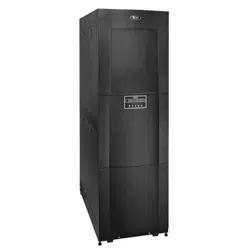
The SRCOOL33K features a built-in condensate removal system that evaporates condensate removed from the air by atomizing it into the
condenser air stream. During normal operation, the amount of water removed from the air is minimal. However, if the amount of water
removed from the air exceeds the capability of the internal removal system (0.85 gal/hr; 3.22 L/hr), the user must re-route the drainage to a
nearby drain using the provided auxiliary drain line.
1
Make sure that the unit is powered down and disconnected from AC input.
2
Open side panel and locate the condensate valve (for more information, see 6.4 Installation in High-Humidity Environments in the
Installation Manual).
3A
Internal Evaporation
Setting: Turn the valve
connected to the evaporator
line counterclockwise and the
valve to the auxiliary drain line
clockwise.
3B
External Drain Setting:
Turn the valve connected
to the auxiliary drain line
counterclockwise and the
valve to the evaporator line
clockwise.
Internal Evaporation
Setting
External Drain
Setting
17-10-239 96-A2AB_RevX1
WATER
FROM
PUMP
WATER
FROM
PUMP
TO
EVAPORATOR
TO
EXTERNAL
DRAIN
Internal Evaporation
Setting
External Drain
Setting
17-10-239 96-A2AB_RevX1
WATER
FROM
PUMP
WATER
FROM
PUMP
TO
EVAPORATOR
TO
EXTERNAL
DRAIN
Loading ...
Loading ...
Loading ...
