
Loading ...
Loading ...
Loading ...
— 17 —
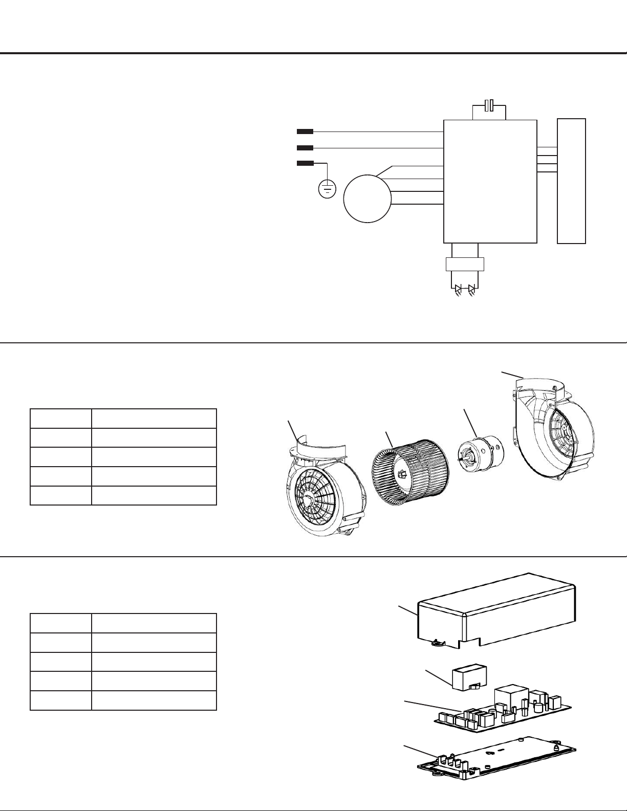
Assembly
Circuit Diagram
Blower Assembly
u
v
w
x
u
v
w
x
Number Part
1 Left blower housing
2 Impeller
3 Motor
4 Right blower housing
Number Part
1
Junctionboxcover
2 Capacitor
3 Main PCB board
4
Junctionboxbottom
Electrical Assembly
AC 0V 60H
z1 2
L
N
E
M
Capacitor
Main PCB
Controls PCB
AC 0V 60Hz1 2
L
N
E
M
Condensateur
Circuit
imprimé nu
principal
Commandes
Circuit imprimé nu
+
_
Driver
+
_
Driver
Loading ...
Loading ...
Loading ...