USER MANUAL
MANUALE D’USO
PLP 50EN
FLUSH-MOUNT
CEILING LOUDSPEAKER
IN COMPLIANCE WITH
EN 54-24 STANDARD
DIFFUSORE ACUSTICO
PER CONTROSOFFITTO
CONFORME ALLA
NORMA EN 54-24
0068
RCF S.p.A. - Via Raffaello Sanzio 13, 42124 Reggio Emilia, ITALY
17
0068-CPR-051/2017
EN 54-24:2008
Loudspeaker for voice alarm systems
for fire detection and fire alarm systems for buildings
PLP 50EN
Provided options:
Type A
Other technical data: see operational manual.
Tutti i requisiti di conformità alla normativa EN54-24:2008 sono verificati nello
All EN54-24:2008 standard requirements are verified in the RCF S.p.A.
manufacturing plant site in Via Raffaello Sanzio 13, 42124 Reggio Emilia, ITALY.
stabilimento produttivo di RCF S.p.A., Via Raffaello Sanzio 13, 42124 Reggio Emilia, ITALY.
The Declaration of Performance is available on the RCF website (www.rcf.it),
in the DOWNLOADS section of the product page.
La Dichiarazione di Prestazione è disponibile sul sito web RCF (www.rcf.it),
nella sezione DOWNLOADS della pagina del prodotto.

TABLE OF CONTENTS
INDICE
ENGLISH
SAFETY AND OPERATING PRECAUTIONS
DESCRIPTION
INSTALLATION
CONNECTION
NOTES ABOUT CONSTANT VOLTAGE SYSTEMS
SPECIFICATIONS
ITALIANO
AVVERTENZE PER LA SICUREZZA E PRECAUZIONI D’USO
DESCRIZIONE
INSTALLAZIONE
COLLEGAMENTO
NOTE SUI SISTEMI A TENSIONE COSTANTE
DATI TECNICI
4
6
6
8
10
11
12
14
14
16
18
19

4
ENGLISH
SAFETY AND OPERATING
PRECAUTIONS
IMPORTANT NOTES
IMPORTANT NOTES
Before connecting and using this product, please read this instruction manual
carefully and keep it on hand for future reference. This manual is to be
considered an integral part of this product and must accompany it when it
changes ownership as a reference for correct installation and use as well as
for the safety precautions.
RCF S.p.A. will not assume any responsibility for the incorrect installation
and / or use of this product.
SAFETY AND OPERATING PRECAUTIONS
1. All the precautions, in particular the safety ones, must be read with special
attention, as they provide important information.
2.
Loudspeaker lines (amplifier outputs) can have a sufficiently high voltage
(i.e. 100-70 V) to involve a risk of electrocution: never install or connect this
loudspeaker when the line is alive.
3. Make sure all connections have been made correctly and the loudspeaker
input voltage is suitable for the amplifier output.
4. Protect loudspeaker lines from damage. Make sure they are positioned in a
way that they cannot be stepped on or crushed by objects.
5. Make sure that no objects or liquids can get into this product, as this may
cause a short circuit.
6. Never attempt to carry out any operations, modifications or repairs that
are not expressly described in this manual.
Contact your authorized service centre or qualified personnel should any of
the following occur:
- The loudspeaker does not function (or works in an anomalous way).
-
The cable has been damaged.
- Objects or liquids have got into the unit.
- The loudspeaker has been damaged due to heavy impacts or fire.
7.
Should the loudspeaker emit any strange smell or smoke, remove it from
the line after having immediately switched the amplifier off.
8. Do not connect this product to any equipment or accessories not foreseen.
For suspended installation, only use the dedicated anchoring points and do
not try to hang this loudspeaker by using elements that are unsuitable or
not specific for this purpose.
Also check the suitability of the support surface to which the product
is anchored (wall, ceiling, structure,
etc.) and the components used for
attachment (screw anchors, screws, brackets not supplied by RCF etc.),
which must guarantee the security of the system / installation over time, also
considering, for example, the mechanical vibrations normally generated by
transducers.

5
ENGLISH
9. RCF S.p.A. strongly recommends this product is only installed by
professional qualified installers (or specialised firms) who can ensure
correct installation and certify it according to the regulations in force.
The entire audio system must comply with the current standards and
regulations regarding electrical systems.
10. Mechanical and electrical factors need to be considered when installing
a professional audio system (in addition to those which are strictly acoustic,
such as sound pressure, angles of coverage, frequency response, etc.).
11. Hearing loss
Exposure to high sound levels can cause permanent hearing loss. The acoustic
pressure level that leads to hearing loss is different from person to person
and depends on the duration of exposure.
To prevent potentially dangerous exposure to high levels of acoustic pressure,
anyone who is exposed to these levels should use adequate protection
devices.
When a transducer capable of producing high sound levels is being used, it is
necessary to wear ear plugs or protective earphones.
See the technical specifications in the instruction manual for the maximum
sound pressure the loudspeaker is capable of producing.
12. To ensure a correct sound reproduction, loudspeaker phase is to be
respected (loudspeakers are connected respecting the amplifier polarity)
This is important when loudspeakers are installed adjacent one another, for
instance, in the same room.
13. To prevent inductive effects from causing hum, noise and a bad system
working, loudspeaker lines should not be laid together with other electric
cables (mains), microphone or line level signal cables connected to amplifier
inputs.
14. The loudspeaker cable shall have wires with a suitable section (twisted,
if possible, to reduce inductive effects due to surrounding electro-
magnetic fields) and a sufficient electrical insulation.
Refer to local
regulations since there may be additional requirements about cable
characteristics.
15. Install this loudspeaker far from any heat source.
16. Do not use solvents, alcohol, benzene or other volatile substances for
cleaning the external parts of this product. Use a dry cloth.
6
ENGLISH
RCF S.P.A. THANKS YOU FOR PURCHASING THIS PRODUCT, WHICH
HAS BEEN DESIGNED TO GUARANTEE RELIABILITY AND HIGH
PERFORMANCE.
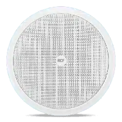
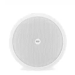
The PLP 50EN ceiling loudspeaker is in compliance with EN 54-24 standard.
It is equipped with a plastic fire dome and can be installed flush-mounted in
f
alse ceilings or panels.
It is particularly suitable for reproducing alarm messages, as it provides particularly
intelligible voice reproduction and it is resistant to the high temperatures that can
be reached during a fire
.
Main features:
- Hi
gh quality voice reproduction.
- 5” loudspeaker.
- Transformer for connection to 100 V (/ 70V) constant voltage lines.
- Possibility to select the output power among several values.
- Steel protection grille.
- Plastic fire dome.
- Ceramic terminal strip for connection (with earth contact).
- Quick system to fix the loudspeaker to the false ceiling through two spring
hooks.
- Fire protection internal cables.
- Thermal fuse that prevents damage to the audio line due to heat on the speaker.
WARNING: MAke suRe thAt the loudspeAkeR Is INstAlled IN A stAble ANd secuRe WAy IN
oRdeR
to AvoId ANy coNdItIoNs thAt MAy be dANGeRous foR peRsoNs oR stRuctuRes.
eNs
uRe the suppoRt suRfAce (e.G. WAll, etc.) hAs the NecessARy MechANIcAl chARActeRIstIcs to
suppoRt the WeIGht of the loudspeAkeR. befoRe INstAllING the loudspeAkeR, cARefully check All
coMpoNeNts to be used ANd MAke suRe theRe Is No dAMAGe, defoRMAtIoN, coRRosIoN ANd/oR
MIssING oR dAMAGed pARts thAt could Reduce the sAfety of the INstAllAtIoN.
IN outdooR use, AvoId INstAllING the loudspeAkeR IN plAces exposed to hARsh WeAtheR coNdItIoNs.
the pl 82eN Is desIGNed foR flush-MouNt INstAllAtIoN IN fAlse ceIlINGs.
befoRe INstAllING the loudspeAkeR, MAke suRe theRe Is suffIcIeNt spAce behINd the fAlse ceIlING
pANel to hold the speAkeR: WIth Respect to the suppoRt suRfAce of the fRoNt flANGe of
the loudspeAkeR, A fRee spAce 100 mm (c. 4”) deep Is NecessARy.
DESCRIPTION
INSTALLATION
7
ENGLISH
ø 151
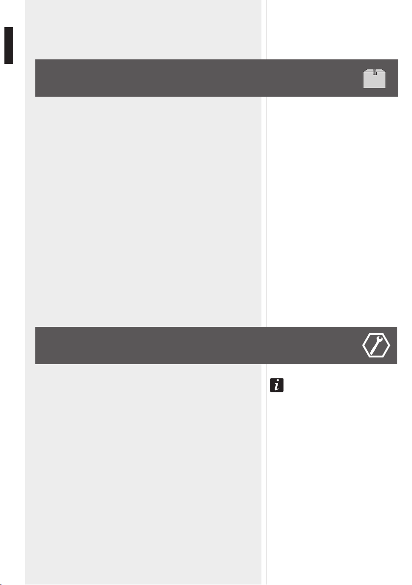
FIGURE 1
FIGURE 2
1. Drill a hole of diameter 151 mm
(5.94”) in the false ceiling panel, as
shown in figure 1.
2.
Loosen the bolt of the fire dome,
which needs to be removed to
access all internal parts.
M
ake the electrical connection as
described in the next section of
the manual, set the desired power
value, then refit the fire dome
through its bolt.
3. Raise the two spring hooks and
insert the speaker into the false
c
eiling as shown in figure 2,
so that it is fixed as shown in the
previous figure 1.
8
ENGLISH
CONNECTION
WARNING: loudspeAkeR coNNectIoNs should be oNly MAde by quAlIfIed ANd expeRIeNced
peRsoNNel hAvING the techNIcAl kNoW-hoW oR suffIcIeNt specIfIc INstRuctIoNs to eNsuRe thAt
coNNectIoNs ARe MAde coRRectly ANd to pReveNt ANy electRIcAl dANGeR.
to pReveNt ANy RIsk of electRIc shock, do Not coNNect loudspeAkeRs WheN the AMplIfIeR Is
sWItched oN. befoRe tuRNING the systeM oN, check All coNNectIoNs ANd MAke suRe theRe
ARe No AccIdeNtAl shoRt cIRcuIts. the eNtIRe souNd systeM shAll be desIGNed ANd INstAlled IN
coMplIANce WIth the cuRReNt locAl lAWs ANd ReGulAtIoNs ReGARdING electRIcAl systeMs.
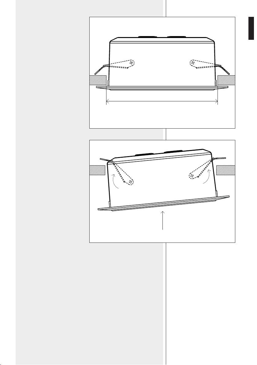
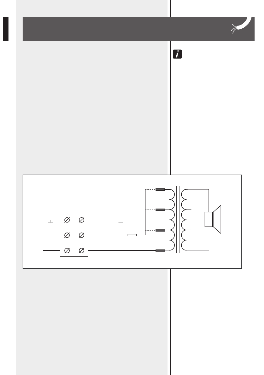
CERAMIC TERMINAL STRIP CONNECTION
The connection to the 100 V (/ 70 V) constant voltage line is made through the
c
eramic terminal strip, which includes a contact for earthing.
Insert the cable through one of the two rubber cable guides of the fire dome.
Connect the positive wire to the speaker input IN 100 V (+) and the negative
wire to IN 0 (–).
Connect the earth wire (yellow-green) to the respective terminal strip contact.
FIGURE 3
CERAMIC SCREW
TERMINAL
100 V RED
GREEN
0 BLACK
COM
6 W
3 W
8 Ω
1.5 W
IN
FUSE
9
ENGLISH
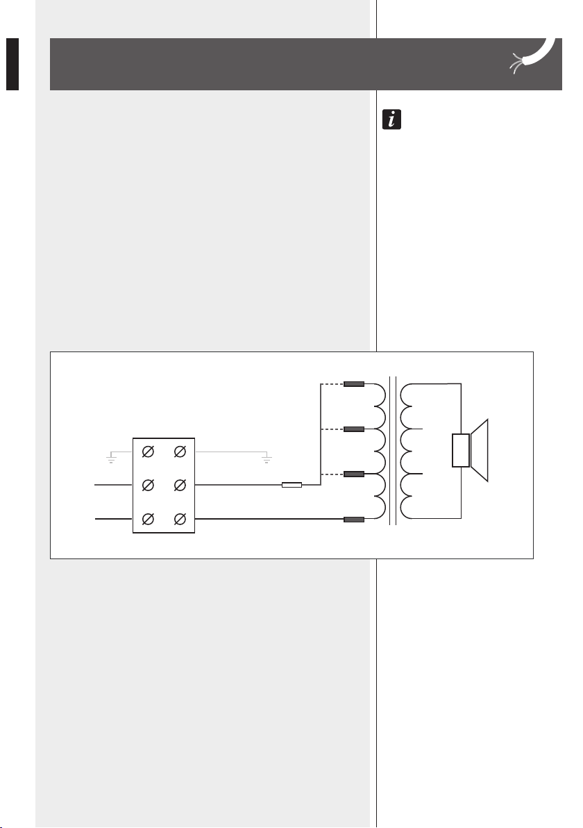
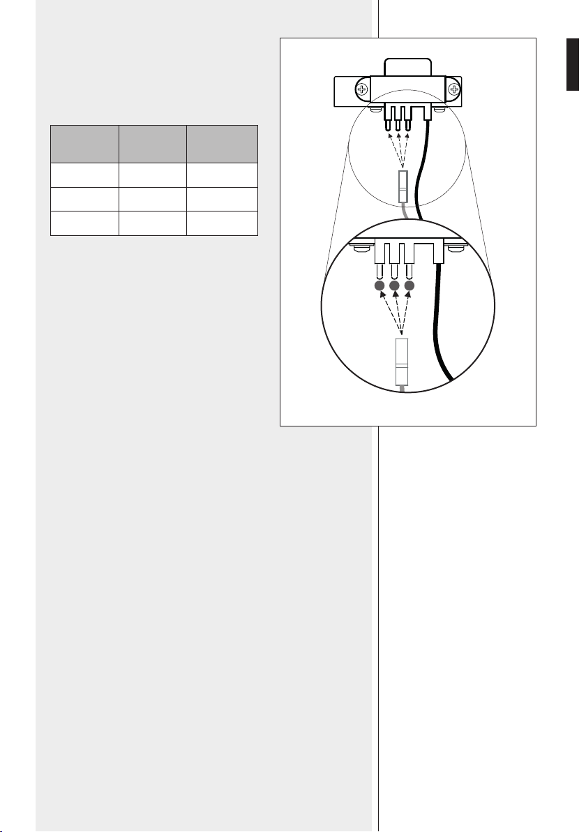
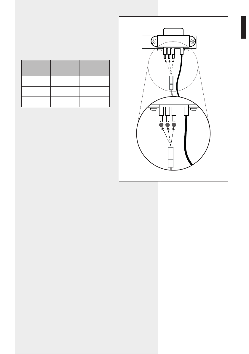
TRANSFORMER POWER SELECTION
Link the ‘TAP’ connector (red wire) to the transformer
contact having the desired power value
(see the next table and the figure 4).
TAP
(pins)
POWER
(100 V)
POWER
(70 V)
1 1.5 W 0.75 W
2 3 W 1.5 W
3 6 W 3 W
FIGURE 4
TAP
1 2 3
10
ENGLISH
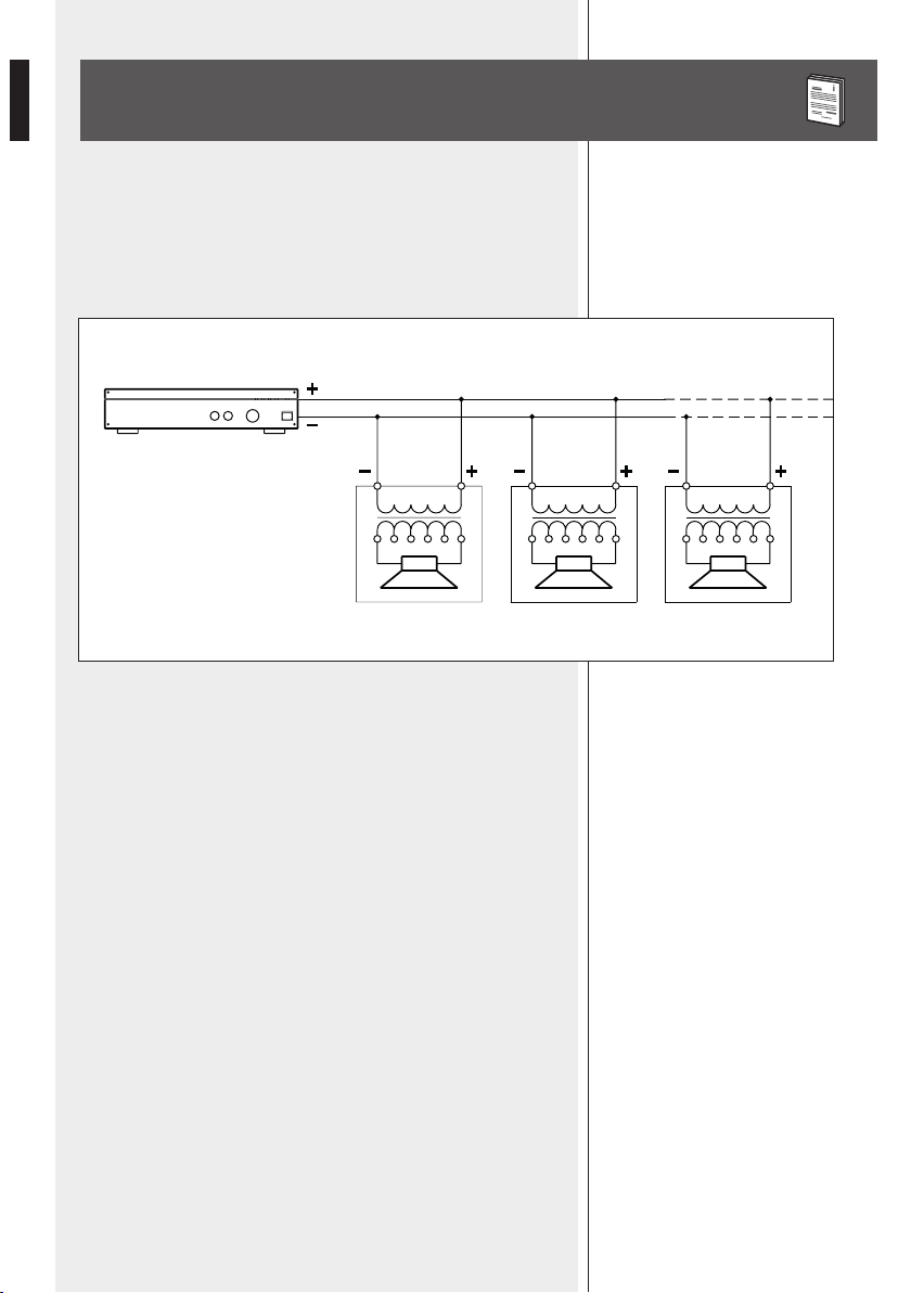
NOTES ABOUT CONSTANT VOLTAGE SYSTEMS
- The loudspeaker input voltage (Vd) shall correspond to the amplifier output
voltage (Va).
- The sum of nominal power values (Pd x n) of all loudspeakers connected to the
line shall not exceed the a
mplifier power (Pa).
- Make sure all loudspeakers are connected in phase to ensure a correct sound
reproduction.
- Always use cables having wires with an adequate cross-section, considering the
cable length and the total loudspeaker power.
- Loudspeaker lines must be kept separated from mains cable, microphone cables
or others, in order to avoid inductive phenomena may cause hum or noises.
- Use loudspeaker cables having twisted wires to reduce hum caused by inductive
effects due to coupling with electromagnetic fields.
AMPLIFIER
Pa = Amplifier power
Pd = Speaker power
n = Number of speakers
Vd = Speaker input voltage
Va = Amplifier output voltag
e
Pa > Pd x n Va
FIGURE 5
11
ENGLISH
SPECIFICATIONS
Input voltage:
Power (selectable) at 100V:
Input impedance:
Frequency response:
Sensitivity:
Max. sound pressure level:
Transducer:
Applicable wire section:
Grille material:
Fire dome material:
Colour:
Connector:
False ceiling cutout size:
Net weight:
Operating temperature:
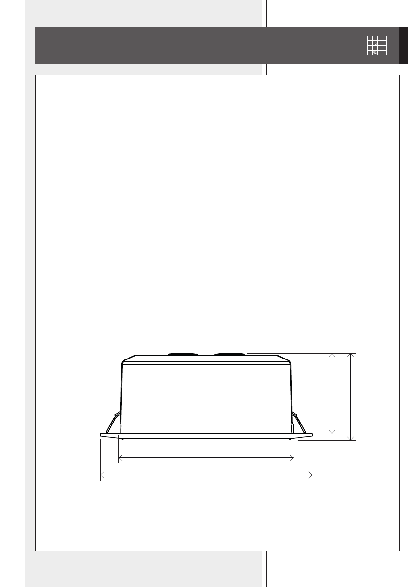
Dimensions:
100 V ( / 70 V)
6 W – 3 W – 1.5 W (power values are halved at 70 V)
1.67 kΩ – 3.33 kΩ – 6.67 kΩ
130 Hz ÷ 20 kHz (–10 dB)
93 dB (1 W, 1 m),
81 dB (1 W, 4 m)
101 dB (6 W, 1 m), 89 dB (6 W, 4 m)
5”
0.8 ÷ 4 mm²
steel
plastic
white
ceramic terminal strip
ø 151 mm (5.94”)
0,63 kg (1,39 lbs)
–30 ÷ +60 °C (–22 ÷ +140 °F)
ø 175 mm (6.89”), h: 71 mm (2.80”)
ø 144
ø 175
71
66
Coverage angle (-6dB) (1): 170° (500 Hz), 165° (1 kHz), 160° (2 kHz), 100° (4 kHz)
IP protection grade: IP 40
(1) Measures made with speaker mounted on a baffle and measurement microphone on the same axis (angle 0°)

12
ITALIANO
AVVERTENZE PER LA SICUREZZA
E PRECAUZIONI D’USO
IMPORTANTE
IMPORTANTE
Prima di collegare ed utilizzare questo prodotto, leggere attentamente
le istruzioni contenute in questo manuale, il quale è da conservare per
riferimenti futuri. Il presente manuale costituisce parte integrante del
prodotto e deve accompagnare quest’ultimo anche nei passaggi di proprietà,
per permettere al nuovo proprietario di conoscere le modalità d’installazione
e d’utilizzo e le avvertenze per la sicurezza.
L’installazione e l’utilizzo errati del prodotto esimono la RCF S.p.A. da ogni
responsabilità.
AVVERTENZE PER LA SICUREZZA E PRECAUZIONI D’USO
1. Tutte le avvertenze, in particolare quelle relative alla sicurezza, devono
essere lette con particolare attenzione, in quanto contengono importanti
informazioni.
2. La linea diffusori (uscita dell’amplificatore) può avere una tensione
sufficientemente alta (e . 100 V) da costituire un rischio di folgorazione per le
persone: non procedere mai all’installazione od alla connessione del diffusore
quando la linea è in tensione.
3. Assicurarsi che tutte le connessioni siano corrette e che la tensione
d’ingresso del diffusore sia compatibile con le caratteristiche d’uscita
dell’amplificatore.
4. Accertarsi che la linea diffusori non possa essere calpestata o schiacciata
da oggetti, al fine di salvaguardarne la perfetta integrità.
5. Impedire che oggetti o liquidi entrino all’interno del prodotto, perché
potrebbero causare un corto circuito.
6.
Non eseguire sul prodotto interventi / modifiche / riparazioni se non quelle
espressamente descritte sul manuale istruzioni.
Contattare centri di assistenza autorizzati o personale altamente qualificato
quando:
- il diffusore non funziona (o funziona in modo anomalo);
- il cavo è danneggiato;
- oggetti o liquidi sono entrati nel diffusore;
- il diffusore non è più integro (a causa di urti / incendio).
7. Nel caso che dal diffusore provengano odori anomali o fumo, spegnere
immediatamente l’amplificatore relativo alla linea e poi scollegare il diffusore.
8. Non collegare a questo diffusore apparecchi ed accessori non previsti.
Quando è prevista l’installazione sospesa, utilizzare solamente gli appositi
punti di ancoraggio e non cercare di appendere il diffusore con elementi non
idonei o previsti allo scopo.
Verificare inoltre l’idoneità del supporto (parete, soffitto, struttura ecc.) e dei
componenti utilizzati per il fissaggio (tasselli, viti, staffe non fornite da RCF
ecc.) che devono garantire la sicurezza dell’impianto / installazione nel

13
ITALIANO
tempo, anche considerando, ad esempio, vibrazioni meccaniche normalmente
generate da un trasduttore.
9. La RCF S.p.A. raccomanda vivamente che l’installazione di questo
prodotto sia eseguita solamente da installatori professionali qualificati
(oppure da ditte specializzate) in grado di farla correttamente e certificarla in
accordo con le normative vigenti.
Tutto il sistema audio dovrà essere in conformità con le norme e le leggi
vigenti in materia di impianti elettrici.
10. Quando si installa un sistema audio professionale, si devono considerare
anche i fattori meccanici ed elettrici (oltre a quelli prettamente acustici, come
la pressione sonora, gli angoli di copertura, la risposta in frequenza, ecc.).
11. Perdita dell’udito
L’esposizione ad elevati livelli sonori può provocare la perdita permanente
dell’udito. Il livello di pressione acustica pericolosa per l’udito varia
sensibilmente da persona a persona e dipende dalla durata dell’esposizione.
Per evitare un’esposizione potenzialmente pericolosa ad elevati livelli di
pressione acustica, è necessario che chiunque sia sottoposto a tali livelli
utilizzi delle adeguate protezioni; quando si fa funzionare un trasduttore in
grado di produrre elevati livelli sonori è necessario indossare dei tappi per
orecchie o delle cuffie protettive.
Consultare i dati tecnici contenuti nel manuale istruzioni per conoscere la
massima pressione sonora che il diffusore acustico è in grado di produrre.
12. I diffusori devono essere collegati in fase (corrispondenza delle
polarità +/– tra amplificatori e diffusori) in modo da garantire una corretta
riproduzione audio, soprattutto quando i diffusori sono collocati in posizione
fr
a loro adiacente o nello stesso ambiente.
13. Per evitare che fenomeni induttivi diano luogo a ronzii, disturbi e
compromettano il buon funzionamento dell’impianto, le linee diffusori
non devono essere canalizzate insieme ai conduttori dell’energia elettrica,
ai cavi microfonici, alle linee di segnale a basso livello che fanno capo ad
amplificatori.
14. Il cavo per il collegamento del diffusore dovrà avere conduttori di sezione
adeguata (possibilmente intrecciati, per minimizzare gli effetti induttivi dovuti
all’accoppiamento con campi elettro-magnetici circostanti) ed un isolamento
idoneo. Riferirsi alle normative locali in quanto potrebbero esserci ulteriori
requisiti riguardanti le caratteristiche del cavo.
15. Collocare il diffusore lontano da fonti di calore.
16. Non usare solventi, alcool, benzina o altre sostanze volatili per la pulitura
delle parti esterne; usare un panno asciutto.
14
ITALIANO
RCF S.P.A. VI RINGRAZIA PER L’ACQUISTO DI QUESTO PRODOTTO,
REALIZZATO IN MODO DA GARANTIRNE L’AFFIDABILITÀ E
PRESTAZIONI ELEVATE.
PLP 50EN è un diffusore acustico a plafoniera conforme alla norma EN 54-
24 e provvisto di fondello antifiamma in plastica
, installabile ad incasso in
controsoffittature o pannelli.
E’ particolarmente indicato per la diffusione di messaggi di allarme: la sua
caratteristica principale è quella di fornire una riproduzione particolarmente
intelligibile della voce e di resistere alle alte temperature che si raggiungono
durante un incendio.
Presenta le seguenti caratte
ristiche:
- elevata qualità della riproduzione della voce;
- altoparlante da 5”;
- trasformatore per il collegamento a linee a tensione costante (100 V);
- possibilità di scegliere la potenza sonora da diffondere fra diversi valori;
- griglia di protezione in acciaio;
- fondello antifiamma in plastica;
- morsettiera in materiale ceramico per il collegamento (con contatto di messa
a terra);
- installazione veloce del diffusore tramite due ganci con molle;
-
cavi interni antifiamma;
- fusibile termico che evita di compromettere l’integrità della linea audio a causa
del calore che interessa il diffusore.
NotA: INstAllARe Il dIffusoRe IN Modo stAbIle e sIcuRo, così dA evItARe quAlsIAsI coNdIzIoNe dI
pe
RIcolo peR l’INcoluMItà dI peRsoNe o stRuttuRe.
coNtRollARe che lA stRuttuRA dI suppoRto (es. coNtRosoffItto, ecc.) AbbIA le NecessARIe
cARAtteRIstIche MeccANIche, tAlI dA coNseNtIRGlI dI soppoRtARe Il peso del dIffusoRe seNzA Il
peRIcolo dI cAdute.
pRIMA dI INstAllARe Il dIffusoRe, coNtRollARe tuttI I coMpoNeNtI dA utIlIzzARe, I quAlI NoN
devoNo pReseNtARe dANNI, defoRMAzIoNI, coRRosIoNI e/o pARtI MANcANtI o
dANNeGGIAte che possoNo RIduRRe lA sIcuRezzA dell’INstAllAzIoNe.
Nell’utIlIzzo All’ApeRto evItARe luoGhI espostI Alle INteMpeRIe.
Il dIffusoRe è stAto studIAto peR esseRe INstAllAto Ad INcAsso IN coNtRosoffIttAtuRe.
pRIMA dell’INstAllAzIoNe veRIfIcARe che dIetRo Al coNtRosoffItto vI sIA uNo spAzIo suffIcIeNte peR
AccoGlIeRe Il dIffusoRe: RIspetto Al pIANo dI AppoGGIo dellA flANGIA fRoNtAle del
dIffusoRe, è NecessARIo uNo spAzIo lIbeRo IN pRofoNdItà dI AlMeNo 100 mm.
DESCRIZIONE
INSTALLAZIONE

15
ITALIANO
ø 151
FIGURA 1
FIGURA 2
1.
Praticare nella controsoffittatura
un foro del diametro di 151 mm,
come indicato in figu
ra 1.
2. Svitare il bullone del fondello, il
quale va rimosso per accedere alle
parti interne.
Effettuare il collegamento elettrico
come descritto nella successiva
sezione del manuale; dopo aver
effettuato tutte le connessioni
(ed impostato la potenza desiderata),
riposizionare il fondello per poi
fissarlo tramite il suo bullone.
3. Sollevare i due ganci a molla ed
inserire il diffusore nel controsoffito
come mostrato
in figura 2, in modo
che sia fissato come nella precedente
figura 1.
16
ITALIANO
COLLEGAMENTO
AtteNzIoNe: peR Il colleGAMeNto del dIffusoRe sI RAccoMANdA dI RIvolGeRsI A peRsoNAle
quAlIfIcAto ed AddestRAto, ossIA peRsoNAle AveNte coNosceNze tecNIche o espeRIeNzA o
IstRuzIoNI specIfIche suffIcIeNtI peR peRMetteRGlI dI ReAlIzzARe coRRettAMeNte le coNNessIoNI e
pReveNIRe
I peRIcolI dell’elettRIcItà. peR evItARe Il RIschIo dI shock elettRIcI, NoN colleGARe Il
dIffusoRe coN l’AMplIfIcAtoRe Acceso. pRIMA dI fAR fuNzIoNARe Il dIffusoRe, è buoNA NoRMA
RIcoNtRollARe tutte le coNNessIoNI, veRIfIcANdo IN pARtIcolAR Modo che NoN vI sIANo deI
coRtocIRcuItI AccIdeNtAlI.
tutto l’IMpIANto dI soNoRIzzAzIoNe dovRà esseRe ReAlIzzAto IN coNfoRMItà coN le NoRMe e le
leGGI vIGeNtI IN MAteRIA dI IMpIANtI elettRIcI.
COLLEGAMENTO DELLA MORSETTIERA CERAMICA
Il collegamento alla linea a tensione costante 100 V (/ 70 V) si realizza tramite la
morsettiera ceramica; è presente inoltre il contatto per la messa a terra.
Inserire il cavo tramite uno dei due passacavi in gomma del fondello.
Collegare il conduttore positivo della linea all’ingresso IN 100 V (+) del diffusore
e quello negativo all’ingresso IN 0 (–).
Collegare il conduttore di protezione (giallo-verde) al contatto della morsettiera
col simbolo di terra.
FIGURA 3
MORSETTIERA
CERAMICA
100 V ROSSO
VERDE
0 NERO
COM
6 W
3 W
8 Ω
1,5 W
IN
FUSIBILE
17
ITALIANO
FIGURA 4
IMPOSTAZIONE DELLA POTENZA
SUL TRAFORMATORE
Collegare il connettore “TAP” (filo rosso) al contatto
del trasformatore di linea avente la potenza
desiderata (vedere la seguente tabella e la figura 4).
TAP
(contatti)
POTENZA
(100 V)
POTENZA
(70 V)
1 1,5 W 0,75 W
2 3 W 1,5 W
3 6 W 3 W
TAP
1 2 3

18
ITALIANO
AMPLIFICATORE
Pa = Potenza amplificatore
Pd = Potenza diffusore
n = Numero diffusori
Vd = Tensione ingresso diffusore
Va = Tensione uscita amplificatore
Pa > Pd x n Va
Vd = Va Vd = Va Vd = Va
NOTE SUI SISTEMI A TENSIONE COSTANTE
- La tensione d’ingresso del diffusore (Vd) deve corrispondere con la tensione
d’uscita dell’amplificatore (Va).
-
La somma delle potenze nominali di tutti i diffusori (Pd x n) collegati alla linea
non deve superare quella del
l’amplificatore (Pa).
- Per garantire una corretta riproduzione audio, effettuare il collegamento di tutti
i diffusori “in fase”.
- Utilizzare dei cavi con conduttori aventi una sezione adeguata, considerando la
loro lunghezza e la potenza complessiva dei diffusori.
- Per evitare che fenomeni induttivi diano luogo a ronzii, disturbi e compromettano
il funzionamento del sistema, i cavi per i diffusori non devono essere canalizzati
assieme ai conduttori dell’energia elettrica, ai cavi microfonici od altre linee.
- Per minimizzare gli effetti induttivi (ronzii) dovuti all’accoppiamento con campi
elettromagnetici circostanti, utilizzare cavi con conduttori intrecciati.
FIGURA 5

19
ITALIANO
DATI TECNICI
Tensione d’ingresso:
Potenza (selezionabile) a 100 V:
Impedenza d’ingresso:
Risposta in frequenza:
Sensibilità:
Max. pressione sonora:
Altoparlante:
Sezione conduttori linea:
Materiale della griglia:
Materiale fondello:
Colore:
Connettore:
Dimensione foro controsoffitto
Peso netto:
Temperatura di funzionamento:
Dimensioni:
100 V ( / 70 V)
6 W – 3 W –1,5 W (i valori sono dimezzati a 70 V)
1,67 kΩ – 3,33 kΩ – 6,67 kΩ
130 Hz ÷ 15 kHz (–10 dB)
93 dB (1 W, 1 m), 81 dB (1 W, 4 m)
101 dB (6 W,
1 m), 89 dB (6 W, 4 m)
5”
0,8 ÷ 4 mm²
acciaio
plastica
bianco
morsettiera ceramica
ø 151 mm
0,63 kg (1,39 lbs)
–30 ÷ +60 °C
ø 175 mm, h: 71 mm
ø 144
ø 175
71
66
Angolo di copertura (-6dB) (1): 170° (500 Hz), 165° (1 kHz), 160° (2 kHz), 100° (4 kHz)
Grado di protezione IP: IP 40
(1) Misure effettuate con diffusore montato su pannello e microfono di misurazione in asse (angolo 0°).

10307569 revC 2023 / 07
www.rcf.it
RCF S.p.A. Italy
Via Raffaello Sanzio, 13
42124 Reggio Emilia - Italy
Tel +39 0522 274 411
Fax +39 0522 232 428
e-mail: info@rcf.it
Salvo eventuali errori ed omissioni.
R
CF S.p.A. si riserva il diritto di apportare modifiche senza preavviso.
Except possible errors and omissions.
RCF S.p.A. reserves the right to make modifications without prior notice.