\Y/t?
\q&
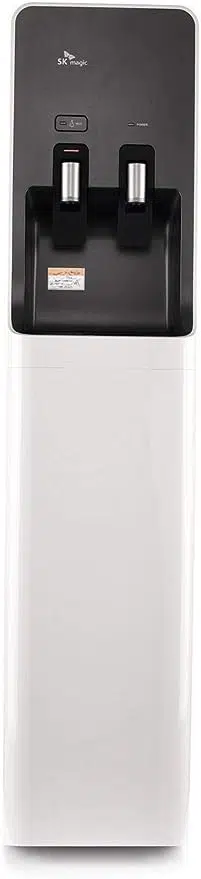
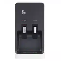
Water
Dispenser
wPU-8900C/F
.
Warnings for safety use
.
Parts
identification
.
lnstallation
guide
.
Operation
guide
.
Sanitisation
instructions
.
Specifications
2-4
p
5-8
p
9p
1op
11p
12p
I
Water Dispenser
I
|
-
xeep tp
insruaim
omrua
in
easry aessoe
rocaix.
I
-.#-=:
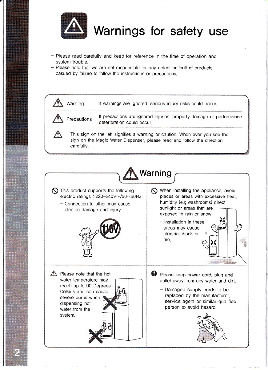
Warnings
for
safety
use
-
Please
read carefully and keep
for reference in the time
ol operation
and
syslem
trouble.
-
Please
note that we
are
nol responsible
for
any defect or fault
of
producls
casued by failure to follow the instructions
or
precautions.
A
Warning
lf warnings
are ignored,
serious injury risks could
occur.
A
precautions
lf
precautions
are
ignored
injuries,
property
damage or
perlormance
...:.r
-
deterioration could occur.
A
This
sign on the left signifies
a
warning
or caution. When
ever
you
see
the
sign on
the lvlagic Water
Dispenser,
please
read
and follow the direction
carelully.
;$warnins
$
fnis
product
supports
the
lollowing
electric ratings
:
22O-240V
-
/
50-60H2.
-
Connection to other may
cause
electric damage and injury
$
Wnen installing
the appliance,
avoid
places
or areas
with
excessive heat,
humidity
(e.g.washrooms)
direct
sunlight or areas that
are
exposed to rain or snow.
-
lnstallation in these
areas
may
cause
electric
shock or
*
fire.
::r.,i
A Please note that the hot
{D
Pt"u."
keep
power
cord,
plug
and
outlet away from any water
and dirt.
-
Damaged
supply cords to be
replaced
by the manulacturer,
service
agent or similar
qualified
person
to avoid hazard.
water temperature may
reach
up to 90 Degrees
Celsius
and can cause
severe burns when
dispensing hot
water lrom the
syslem.

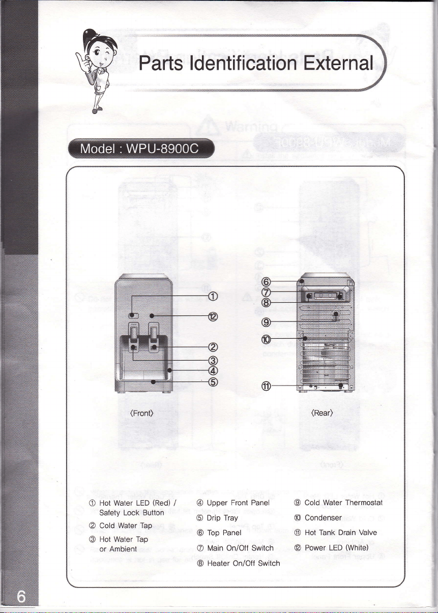
Parts
ldentification External
(Front)
(Rear)
O
Hot Water LED
(Red)
/
Safety Lock Button
@
Cold
Water Tap
@
Hot
Water
Tap
or
Ambienl
@
Upper
Front Panel
@
Drip Tray
@
Top
Panel
@
Main On/Oft Switch
@
Heater On/Olf Swilch
@
Cold Water Thermostat
@
Condenser
@
Hot Tank Drain
Valve
@
Power LED
(White)
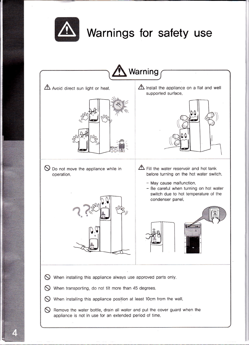
Warnings
for
safety use
Awarning
.A
nvoiO direct sun light or
heat.
/t\
lnstall the appliance on a
flat
and
well
supported surface.
K\
Do nol move the appliance
while an
operation.
A
fitt tnu water reservoir and
hot tank
betore
turning on
the hot water switch.
-
May cause
malfunction.
-
Be
careful
when turning on
hot water
switch
due to
hot temperature of the
condenser
panel.
&
s
s
(\
\>,
When installing this appliance always
use approved
parts
only.
When transporting, do
not tilt more than 45 degrees.
When installing this appliance
position
at least locm lrom
the wall.
Remove
the
water
bottle,
drain all
water
and
put
the cover
guard
when the
appliance
is not in use for an extended
period
of
time.

Parts
ldentification
External
(Front)
O
Hot Water
LED
(Red)
/
Salety Lock Button
@
Cold Water
Tap
@
Hot Water
Tap
or Ambient
@
Upper Front
Panel
@
Drip
Tray
@
Lower Front
Panel
@
Top
Panel
@
Main
On/Olf
Switch
@
Heater
On/Off
Swltch
(Rear)
@
Cold
Water Thermostat
@
Condenser Panel
@
Power
LED
(White)
Parts
ldentification External
(Front)
(Rear)
O
Hot Water LED
(Red)
/
Safety Lock Button
@
Cold
Water Tap
@
Hot
Water
Tap
or
Ambienl
@
Upper
Front Panel
@
Drip Tray
@
Top
Panel
@
Main On/Oft Switch
@
Heater On/Olf Swilch
@
Cold Water Thermostat
@
Condenser
@
Hot Tank Drain
Valve
@
Power LED
(White)
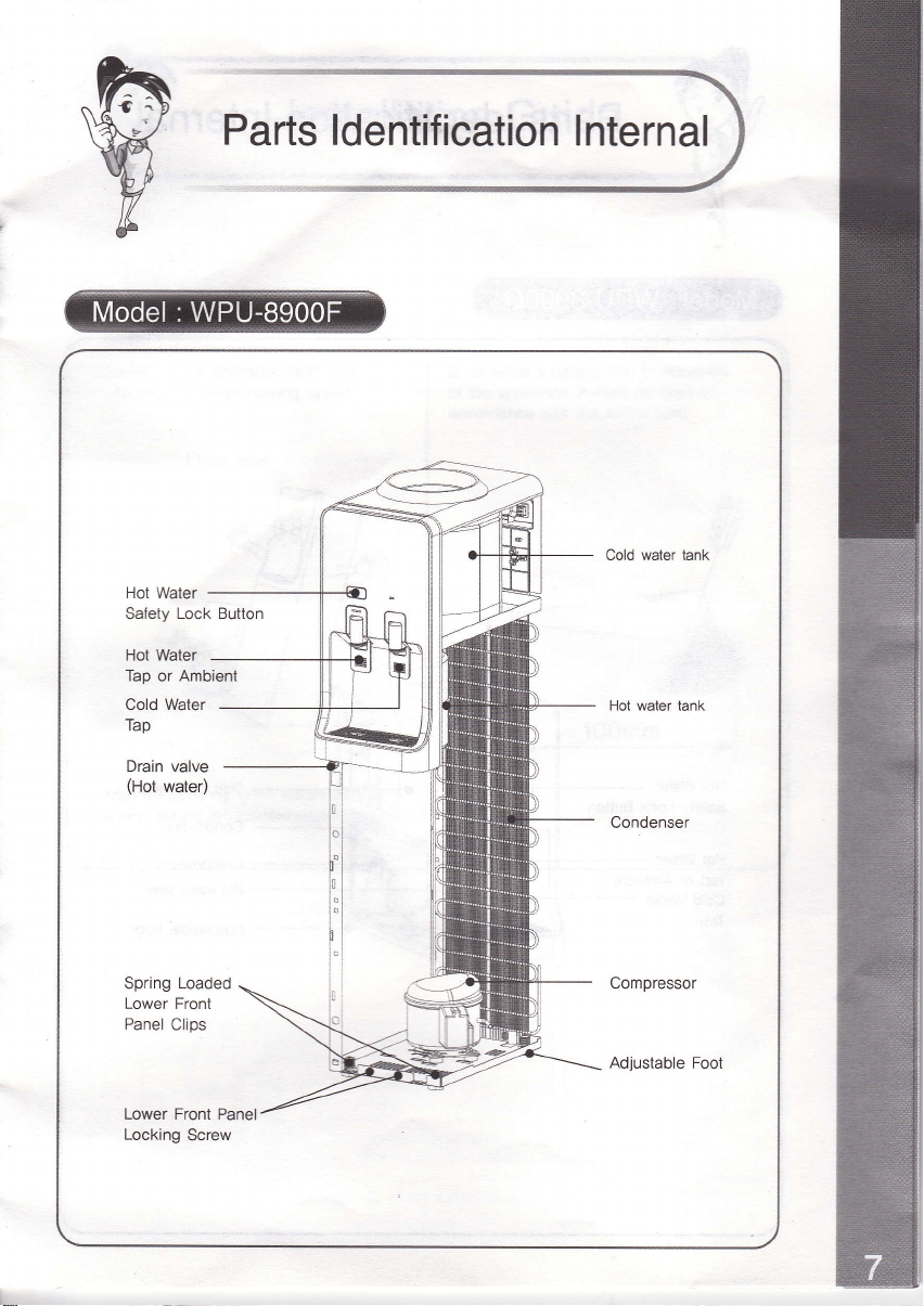
Parts
ldentification
lnternal
Cold water tank
Safety
Lock Button
Hot Water
Tap or Ambient
Cold
Water
Tap
Hot water tank
Drain valve
(Hot
water)
Compressor
Adjustable
Foot
Lower Front Panel
Locking
Screw
t*.
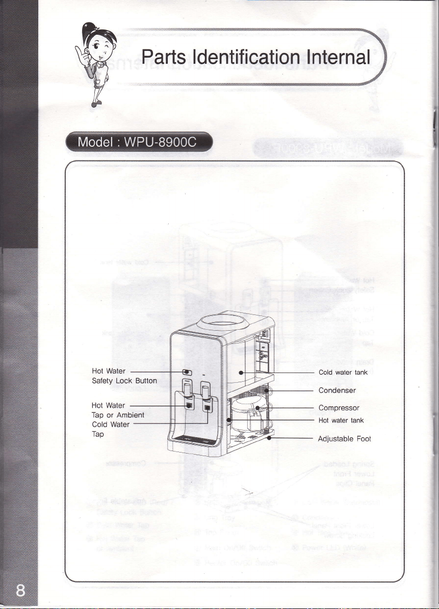
Parts Identification
lnternal
Hot Water
Cold
water tank
Condenser
Compressor
Hot water tank
Adjustable Fool
Safety
Lock Button
Hot Water
Tap or Ambieni
Cold Water
Tap
Sanitisation
instructions
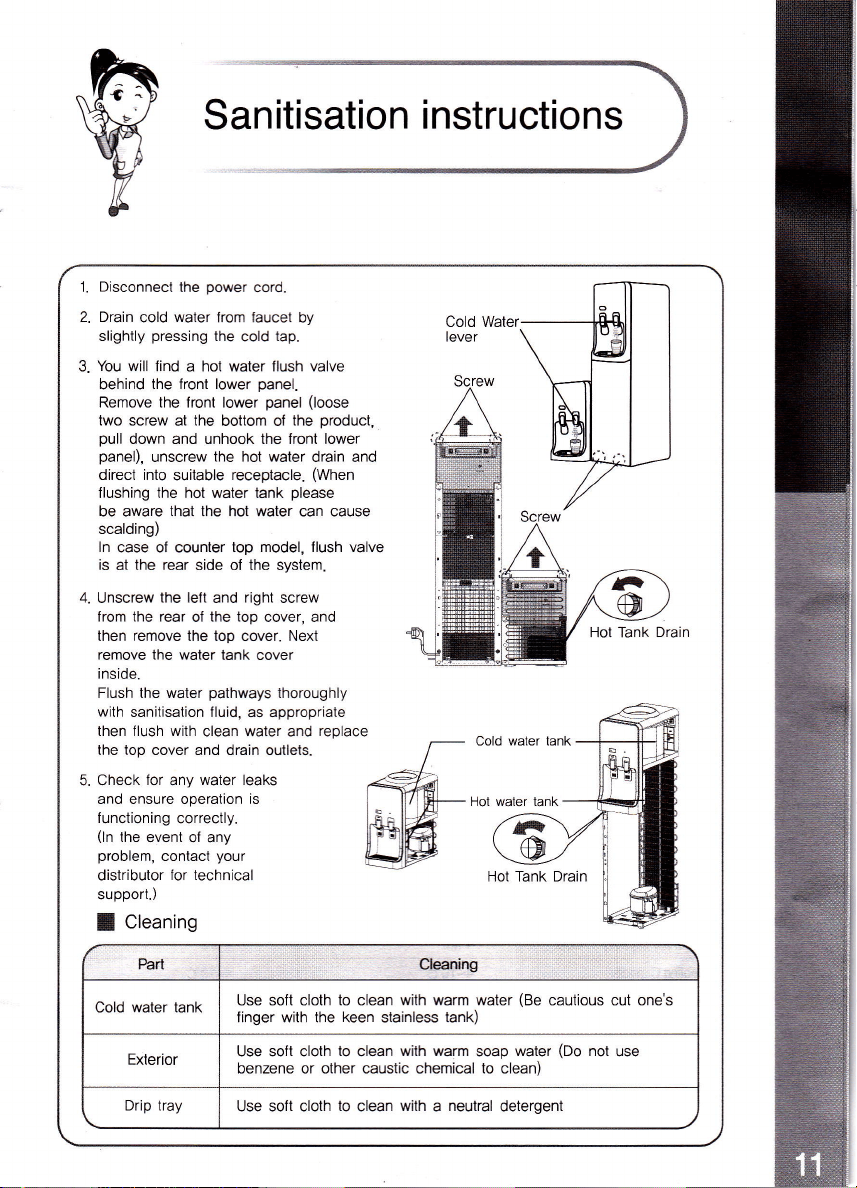
1.
Disconnect
the
power
cord.
2. Druin
cold
water
lrom laucet by
slightly
pressing
the
cold
tap.
3.
You will
lind a hot water flush valve
behind
the front lower
panel.
Remove the front lower
panel
(loose
two screw
at
lhe
bottom of
the
product,
pull
down and unhook the front lower
panel),
unscrew
the hot water
drain and
direct into
suitable
receptacle.
(When
llushing the hot water tank
please
be aware
that
the hot water can cause
scalding)
In
case of counter
top model, flush valve
is at the
rear
side ol the system.
4.
Unscrew
the lelt
and
right
screw
from the rear
of
the top
cover, and
then remove the top cover. Next
remove the water
lank cover
inside.
Flush the water
pathways
thoroughly
with
sanitisation fluid,
as
appropriate
then flush with
clean water and
replace
the top cover and drain outlets.
5. Check
for
any
water leaks
and ensure operation is
f
unctioning correctly.
(ln
the event
of any
problem,
contact
your
distributor
for technical
support.)
I
Cleaning
Cold Water
lever
Screw
,%rt eaoing
Cold water tank
Use
soft cloth to clean with warm water
(Be
cautious cut one's
linger with the keen stainless tank)
Exterior
Use soft cloth
to
clean
with warm
soap
water
(Do
not
use
benzene or other caustic chemical to clean)
Drip lrav
Use soft cloth
to
clean
with
a
neutral
detergent