
FR
FR
Printing: November 2022 (01)
Publication No.: OM23EN-0T33E0EUR
Printed in France
Nissan Automotive Europe SAS - France
X-TRAIL
OWNER'S MANUAL
NISSAN X-TRAIL
T33-EN1
T33-EN1
OM23EN-0T33E0EUR
T33
EN

(3,1)
This manual was prepared to help you understand
the operation and maintenance of your vehicle so
that you may enjoy many kilometers (miles) of
driving pleasure. Please read through this manual
before operating your vehicle.
A separate Warranty Information & Maintenance
Booklet explains details about the warranties
covering your vehicle.
Your NISSAN dealer or qualified workshop knows
your vehicle best. When you require any service or
have any questions, we will be glad to assist you
with the extensive resources available for you.
IMPORTANT SAFETY INFORMATION
Reminders for safety!
Follow these important driving rules to help ensure
a safe and complete trip for you and your
passengers!
* NEVER drive under the influence of alcohol
or drugs.
* ALWAYS observe posted speed limits and
never drive too fast for conditions.
* ALWAYS use your seat belts and appropriate
child restraint systems. Preteen children
should be seated in the rear seat.
* ALWAYS provide information about the
proper use of vehicle safety features to all
occupants of the vehicle.
* ALWAYS review this Owner’s Manual for
important safety information.
When reading the manual
This manual includes information for all options
available on this model. Therefore, you may find
some information that does not apply to your
vehicle.
Throughout this manual, some illustrations may
only show the layout for Left-Hand Drive (LHD)
models. For Right-Hand Drive (RHD) models, the
illustrated shape and location of some compo-
nents may differ.
All information, specifications and illustrations in
this manual are those in effect at the time of
printing. NISSAN reserves the right to change
specifications or designs without notice and with-
out obligation.
MODIFICATION OF YOUR VEHICLE
This vehicle should not be modified. Modification
could affect its performance, safety or durability,
and may even violate governmental regulations. In
addition, damage or performance problems result-
ing from modifications may not be covered under
NISSAN warranties.
Read first — then drive safely
Before driving your vehicle, read this Owner’s
Manual carefully. This will ensure familiarity with
controls and maintenance requirements, assisting
you in the safe operation of your vehicle.
Throughout this manual we have used the symbol
followed by the word WARNING. This is
used to indicate the presence of a hazard that
could cause death or serious personal injury. To
avoid or reduce the risk, the procedures must be
followed precisely.
The symbol
followed by the word CAUTION
is also used throughout this manual to indicate the
presence of a hazard that could cause minor or
moderate personal injury or damages to your
vehicle. To avoid or reduce the risk, the procedures
must be followed carefully.
MSIC0697
If you see this symbol, it means “Do not do this” or
“Do not let this happen”.
If you see a symbol similar to these in an
illustration, it means the arrow points to the front
of the vehicle.
Arrows in an illustration that are similar to these
indicate movement or action.
Foreword
T33
EN
EN
T33
(4,1)
Arrows in an illustration that are similar to these
call attention to an item in the illustration.
Trademarks:
MNOS1617
Bluetooth® is a trademark
owned by Bluetooth SIG, Inc.
and licensed to Visteon Cor-
poration.
Air bag warning label:
MWAB0183X
“NEVER use a rearward facing child restraint on a
seat protected by an ACTIVE AIR BAG in front of it,
DEATH or SERIOUS INJURY to the CHILD can occur.”
Be sure to read “Air bag warning labels” (P.50).
© 2022 NISSAN MOTOR CO., LTD.

(2,1)

(1,1)
Illustrated table of contents
0
Safety — seats, seat belts and supplemental restraint
system
Instruments and controls
Pre-driving checks and adjustments
Monitor, heater, air conditioner, audio and phone
systems
Starting and driving
In case of emergency
Appearance and care
Maintenance and do-it-yourself
Technical information
Index
1
2
3
4
5
6
7
8
9
10
Contents

(2,1)

(5,1)
0 Illustrated table of contents
Seats, seat belts and Supplemental Restraint
System (SRS) .......................................................................................................... 2
Exterior front .......................................................................................................... 3
Exterior rear ............................................................................................................ 4
Passenger compartment ............................................................................. 5
Cockpit ........................................................................................................................ 6
Left-Hand Drive (LHD) model .......................................................... 6
Right-Hand Drive (RHD) model ...................................................... 7
Instrument panel
....
............................................................................................ 9
Left-Hand Drive (LHD) model
....
...................................................... 9
Right-Hand Drive (RHD) model
....
.............................................. 10
Meters and gauges
....
................................................................................... 11
Models with analog meter and colour display
....
......... 11
Models with full-screen display
....
............................................ 12
Engine compartment
....
.............................................................................. 13
KR15DDT engine model
....
............................................................. 13
(6,1)
2 Illustrated table of contents
MEVT33A1-DAB0E57A-1DBE-462B-9A3F-5EFEB61E5B2A
MWAA0408X
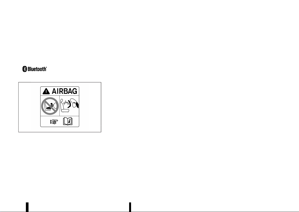
1. Supplemental front-impact air bags (P.47)
2. Front passenger air bag status light (P.53)
3. Occupant classification sensor (front pas-
senger seat) (P.52)
4. Front central side-impact supplemental air
bag (P.47)
5. Seat belts (P.28)
6. Head restraints (P.25)
7. Supplemental curtain side-impact air bags
(P.47)
8. Second row seat armrest (P.24)
9. Front seats (P.16)
10. Supplemental side-impact air bags (P.47)
11. Pre-tensioner seat belts (P.58)
12. Second row seats (P.20)
— Child restraints (P.33)
13. ISOFIX child restraint system (for second row
seats) (P.39)
14. Child restraint anchor points (for top tether
strap) (P.40)
15. Third row seats* (P.23)
*: where fitted
SEATS, SEAT BELTS AND SUPPLE-
MENTAL RESTRAINT SYSTEM (SRS)
SEATS, SEAT BELTS AND SUPPLEMENTAL RESTRAINT SYSTEM (SRS)
(7,1)
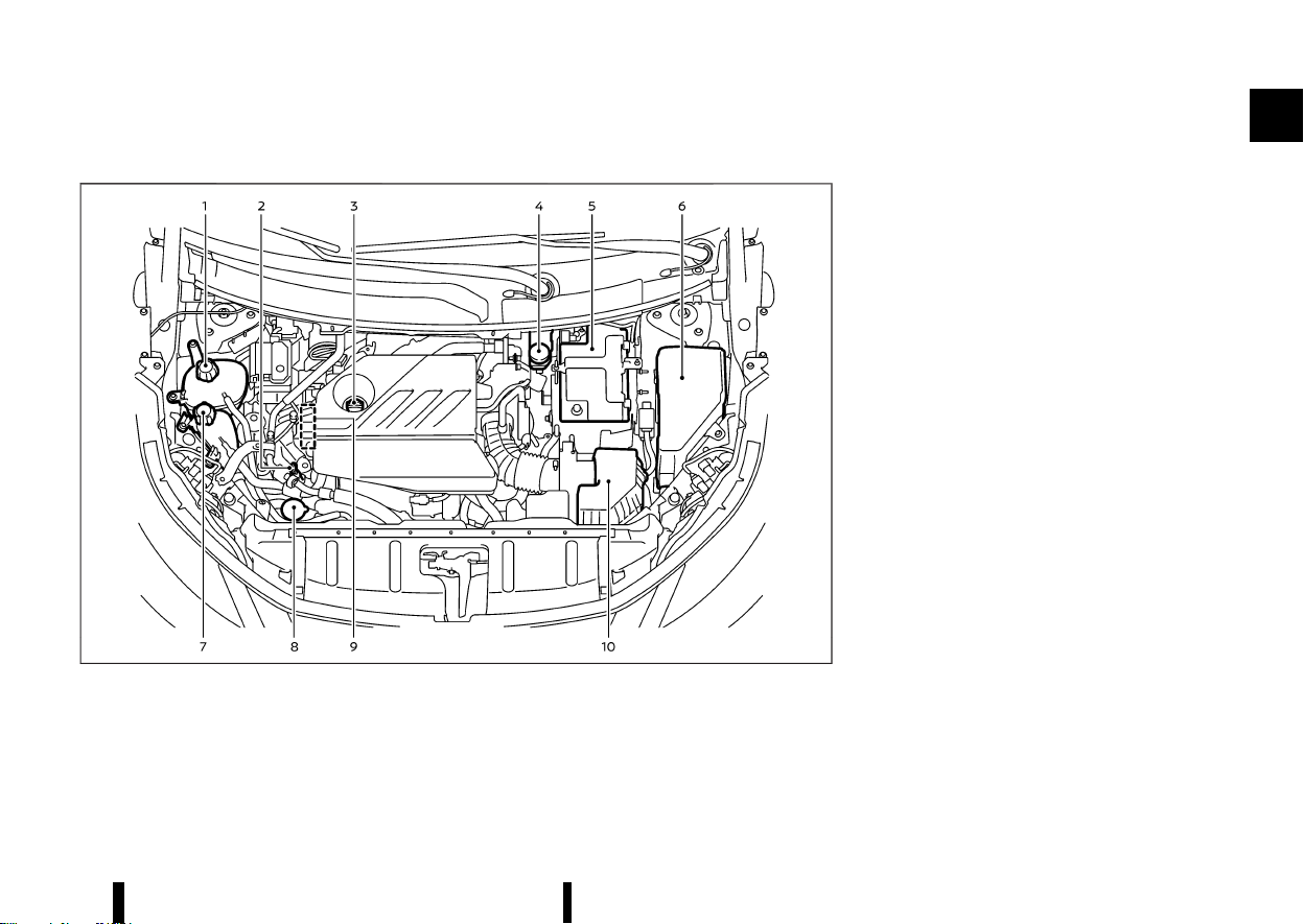
MEVT33A1-04689E16-8F3A-42EF-A6C5-CB2200C3C4DF
MWAA0410X
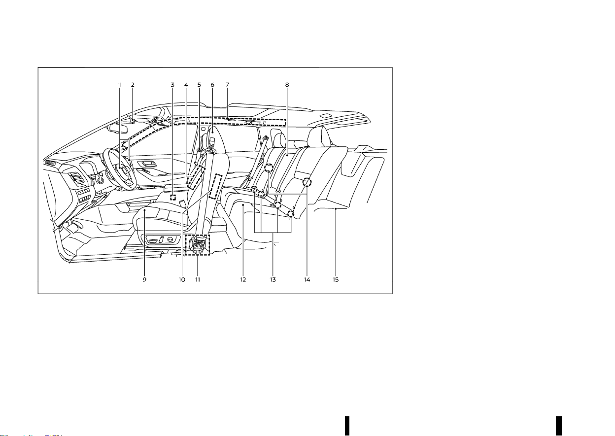
1. Bonnet (P.159)
2. Windscreen wiper and washer
— Switch operation (P.116)
— Window washer fluid (P.437)
3. Front camera* (P.109, P.271, P.274, P.277,
P.329, P.359)
4. Sunroof* (P.135)
5. Power windows (P.133)
6. Side turn signal lights (P.115)
7. Recovery hook (P.413)
8. Parking sensors (centre and corner)*
— Parking sensor (sonar) system (P.395)
9. Front view camera* (P.191)
10. Fog lights* (P.115)
11. Headlights and turn signal lights (P.108)
12. Headlight cleaner* (P.117)
13. Tyres
— Tyres and wheels (P.448, P.461)
— Emergency tyre puncture repair kit (P.405)
— Tyre Pressure Monitoring System (TPMS)
(P.77, P.240)
14. Outside rearview mirrors (P.168)
15. Side view camera* (P.191)
16. Doors
— Keys (P.142)
— Door locks (P.143)
— Intelligent Key system (P.146)
— Security system (P.157)
*: where fitted
Illustrated table of contents 3
EXTERIOR FRONT
EXTERIOR FRONT
(8,1)
4 Illustrated table of contents
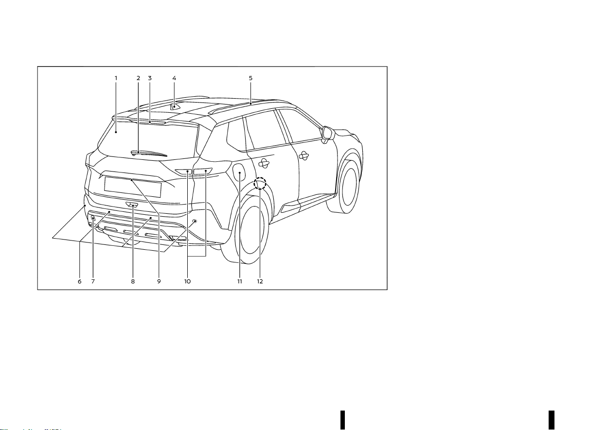
MEVT33A1-7B2C2654-E417-4868-A66F-9312AADDC7F8
MWAA0416X
1. Rear window defogger (P.119)
2. Rear window wiper and washer
— Switch operation (P.118)
— Window washer fluid (P.437)
3. High-mounted brake light (P.444)
4. Antenna (P.225)
5. Roof rack* (P.132)
6. Parking sensors (centre and corner)
— Parking sensor (sonar) system (P.395)
— Rear Automatic Braking (RAB)* (P.377)
7. Recovery hook (P.413)
8. Back door (P.160)
— Intelligent Key system* (P.146)
9. Rear view camera* (P.185, P.191)
10. Rear combination lights (P.444)
— Rear fog light (driver’s side) (P.116)
11. Fuel-filler lid (P.164)
— Fuel information (P.458)
12. Child safety rear door locks (P.146)
*: where fitted
EXTERIOR REAR
EXTERIOR REAR
(9,1)
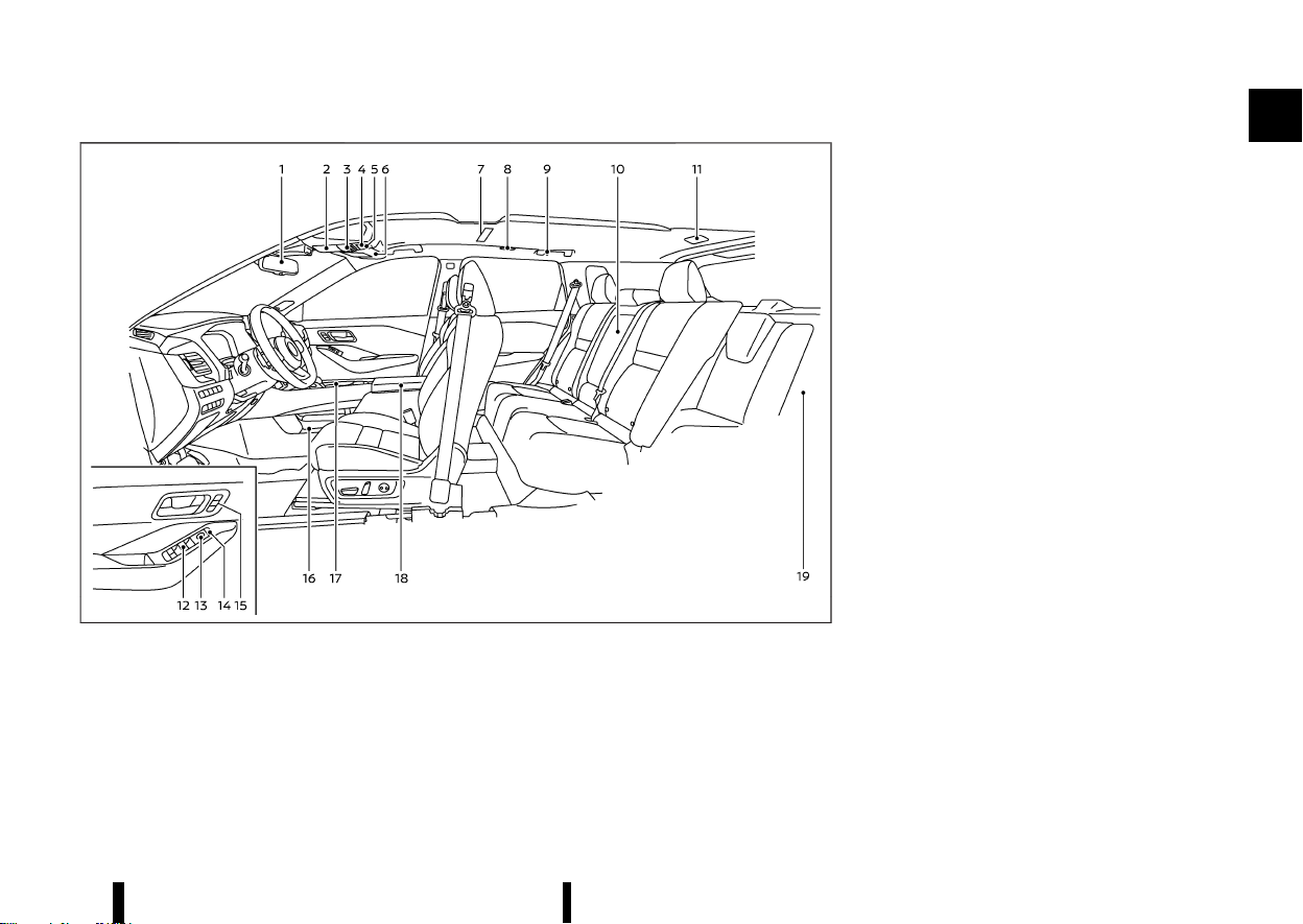
MEVT33A1-9E322059-36C4-4189-9129-B39018B7BB4F
MWAA0411X
1. Inside rearview mirror (P.167)
2. Sunglasses holder (P.128)
3. Map lights (P.138)
— Microphone**
4. Sunroof switch* (P.135)
5. SOS button* (P.124)
6. Sun visors (P.137)
7. Room light* (P.138)
8. Rear personal lights* (P.138)
9. Coat hooks (P.129)
10. Rear cup holders (P.127)
11. Cargo light (P.139)
12. Power window switches (P.133)
13. Outside rearview mirror control switches
(driver’s side) (P.168)
14. Power door lock switches (P.145)
15. Automatic drive positioner switches* (driver’s
and front passenger’s side*) (P.169)
16. Lower console tray (P.128)
17. Front cup holders (P.127)
18. Console box (P.128)
— USB (Universal Serial Bus) charging con-
nector (back side)* (P.122)
— Rear temperature control* (P.212)
19. Cargo area
— Adjustable luggage floor* (P.130)
— Luggage hooks (P.130)
— Tonneau cover (P.129)
— Emergency tyre puncture repair kit (P.405)
— Power outlet (P.122)
*: where fitted
**: Refer to the separate NissanConnect Own-
er’s Manual (where fitted).
Illustrated table of contents 5
PASSENGER COMPARTMENT
PASSENGER COMPARTMENT
(10,1)
6 Illustrated table of contents
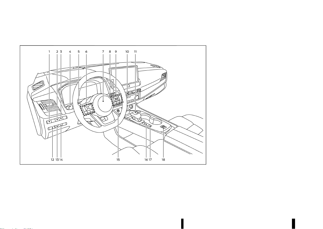
MEVT33A1-43D1CCA9-6102-4D82-BC6B-C3655BBF5529
LEFT-HAND DRIVE (LHD) MODEL
MEVT33A1-46004215-E835-4FF4-BDD6-5CE21CEBAF92
MWAA0463X
1. Headlight aiming control switch* (P.112)
2. Steering Assist switch* (models with ProPI-
LOT Assist) (P.329) or dynamic driver assis-
tance switch* (models without ProPILOT
Assist) (P.277, P.295)
3. Head Up Display (HUD) switch* (P.105)
4. Headlight and turn signal switch (P.108)/Fog
light switch (P.115)
5. Paddle shifters (P.253)
6. Steering-wheel-mounted controls (left side)
— Audio control (P.225 or **)
— Vehicle information display control (P.82)
7. Steering wheel (P.166)
— Horn (P.120)
8. Wiper and washer switch (P.116)
9. Steering-wheel-mounted controls (right
side)
— Speed limiter switches* (P.309)
— Cruise control switches* (P.311)
— Intelligent Cruise Control (ICC) switches*
(P.313)
— ProPILOT Assist switches* (P.277, P.295,
P.329)
— Bluetooth® Hands-Free Phone System
switches (P.226 or **)
— Voice Recognition system switch**
10. Hazard indicator flasher switch (P.404)
11. Shift lever
— Continuously Variable Transmission (CVT)
(P.250)
12. Instrument brightness control (P.71)
13. Stop/Start OFF switch (P.260)
14. Power back door switch* (P.160)
15. Push-button ignition switch (P.245)
16. Parking brake switch (P.171)
17. Automatic brake hold switch (P.173)
18. Drive Mode Selector (P.248)
*: where fitted
**: See the separate NissanConnect Owner’s
Manual (where fitted).
COCKPIT
COCKPIT
(11,1)
RIGHT-HAND DRIVE (RHD) MODEL
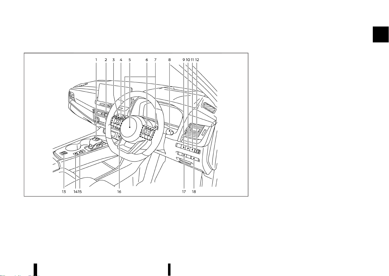
MEVT33A1-C6DF7CEB-3288-4AA6-B251-B300B7DA4225
MWAA0413X
1. Shift lever
— Continuously Variable Transmission (CVT)
(P.250)
2. Hazard indicator flasher switch (P.404)
3. Headlight and turn signal switch (P.108)/Fog
light switch (P.115)
4. Steering-wheel-mounted controls (left side)
— Audio control (P.225 or **)
— Vehicle information display control (P.82)
5. Steering wheel (P.166)
— Horn (P.120)
6. Steering-wheel-mounted controls (right
side)
— Speed limiter switches* (P.309)
— Cruise control switches* (P.311)
— Intelligent Cruise Control (ICC) switches*
(P.313)
— ProPILOT Assist switches* (P.277, P.295,
P.329)
— Bluetooth® Hands-Free Phone System
switches (P.226 or **)
— Voice Recognition system switch**
7. Paddle shifters (P.253)
8. Wiper and washer switch (P.116)
9. Head Up Display (HUD) switch* (P.105)
10. Steering Assist switch* (models with ProPI-
LOT Assist) (P.329) or dynamic driver assis-
tance switch* (models without ProPILOT
Assist) (P.277, P.295)
11. Stop/Start OFF switch (P.260)
12. Headlight aiming control switch* (P.112)
13. Drive Mode Selector (P.248)
14. Automatic brake hold switch (P.173)
15. Parking brake switch (P.171)
16. Push-button ignition switch (P.245)
17. Power back door switch* (P.160)
18. Instrument brightness control (P.71)
*: where fitted
Illustrated table of contents 7

(12,1)
8 Illustrated table of contents
**: See the separate NissanConnect Owner’s
Manual (where fitted).
(13,1)
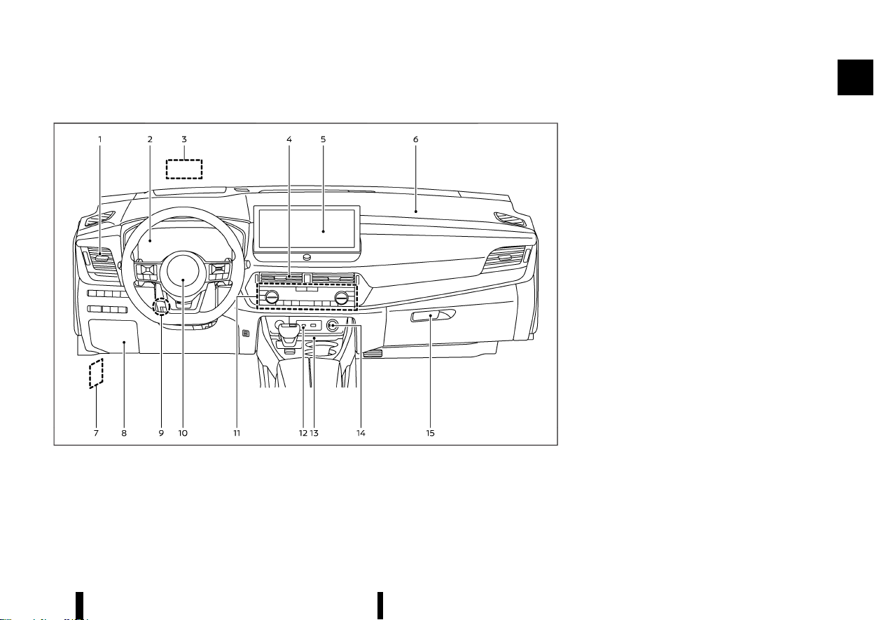
MEVT33A1-EA4C77B0-5D9D-4C73-9A97-F1B173E93135
LEFT-HAND DRIVE (LHD) MODEL
MEVT33A1-8F25FA5D-0863-483E-B60A-D39331DBC3F4
MWAA0414X
1. Side vent (P.203)
2. Meters and gauges (P.67)/Clock (P.105)
3. Head Up Display (HUD)* (P.105)
4. Centre vent (P.203)
5. Audio system (P. 213 or **) or navigation
system**
— Rear view monitor* (P.185)
— Intelligent Around View Monitor* (P.191)
— Bluetooth® Hands-Free Phone System (P.
226 or **)
— Clock (P. 218 or **)
6. Front passenger supplemental air bag (P.47)
7. Bonnet release handle (P.159)
8. Fuse box cover (P.442)
9. Tilt and telescopic steering lock lever (P.166)
10. Driver supplemental front-impact air bag
(P.47)
11. Heater and air conditioner control (P.204)
— Defogger switch (P.119)
— Heated seat switches* (P.19)
— Heated steering wheel switch* (P.120)
— Heated windscreen* (P.119)
12. USB (Universal Serial Bus) connection port(s)
(P. 224 or **)
13. Wireless charger* (P.123)
14. Power outlet (P.122)
15. Glove box (P.128)
*: where fitted
**: See the separate NissanConnect Owner’s
Manual (where fitted).
Illustrated table of contents 9
INSTRUMENT PANEL
INSTRUMENT PANEL
(14,1)
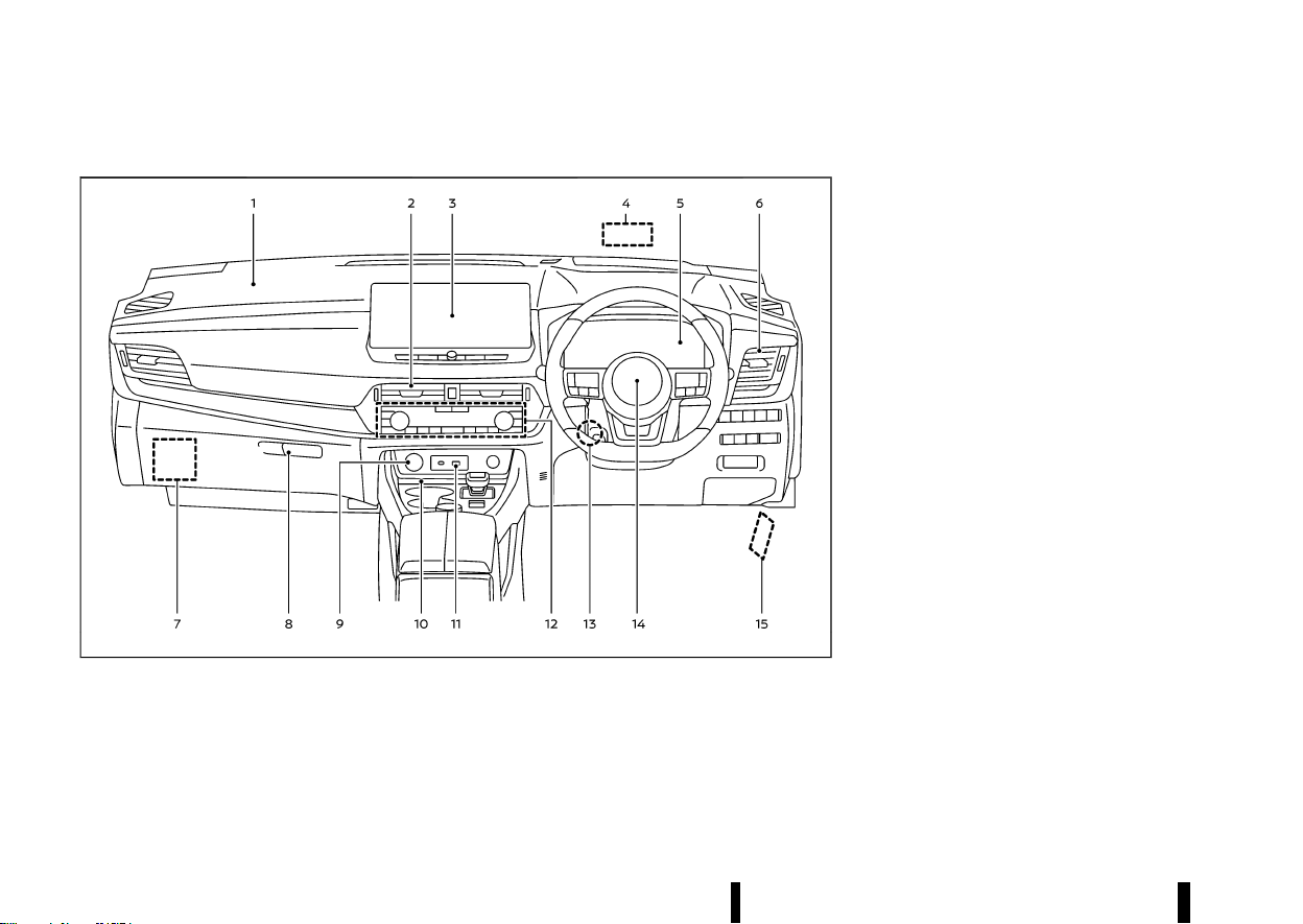
10 Illustrated table of contents
RIGHT-HAND DRIVE (RHD) MODEL
MEVT33A1-AC1ED179-5C61-45C9-BDE4-35FFD848EAC8
MWAA0415X
1. Front passenger supplemental air bag (P.47)
2. Centre vent (P.203)
3. Audio system (P. 213 or **) or navigation
system**
— Rear view monitor* (P.185)
— Intelligent Around View Monitor* (P.191)
— Bluetooth® Hands-Free Phone System (P.
226 or **)
— Clock (P. 218 or **)
4. Head Up Display (HUD)* (P.105)
5. Meters and gauges (P.67)/Clock (P.105)
6. Side vent (P.203)
7. Fuse box cover (P.442)
8. Glove box (P.128)
9. Power outlet (P.122)
10. Wireless charger* (P.123)
11. USB (Universal Serial Bus) connection port(s)
(P. 224 or **)
12. Heater and air conditioner control (P.204)
— Defogger switch (P.119)
— Heated seat switches* (P.19)
— Heated steering wheel switch* (P.120)
— Heated windscreen* (P.119)
13. Tilt and telescopic steering lock lever (P.166)
14. Driver supplemental front-impact air bag
(P.47)
15. Bonnet release handle (P.159)
*: where fitted
**: See the separate NissanConnect Owner’s
Manual (where fitted).
(15,1)
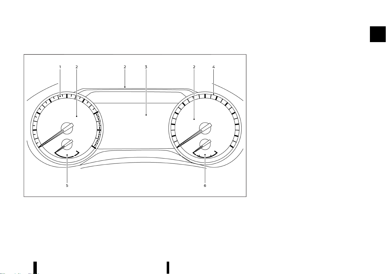
MEVT33A1-ADD7704B-E089-476F-B602-46E63AF51822
MODELS WITH ANALOG METER AND COLOUR DISPLAY
MEVT33A1-1EF10AF3-8EBF-4883-AC98-5402B6ADBBDE
MWAA0409X
Example
1. Tachometer (P.70)
2. Warning and indicator lights (P.74)
3. Vehicle information display (P.81)
— Odometer (P.69)
4. Speedometer (P.69)
5. Engine coolant temperature gauge (P.70)
6. Fuel gauge (P.71)
Illustrated table of contents 11
METERS AND GAUGES
METERS AND GAUGES
(16,1)
12 Illustrated table of contents
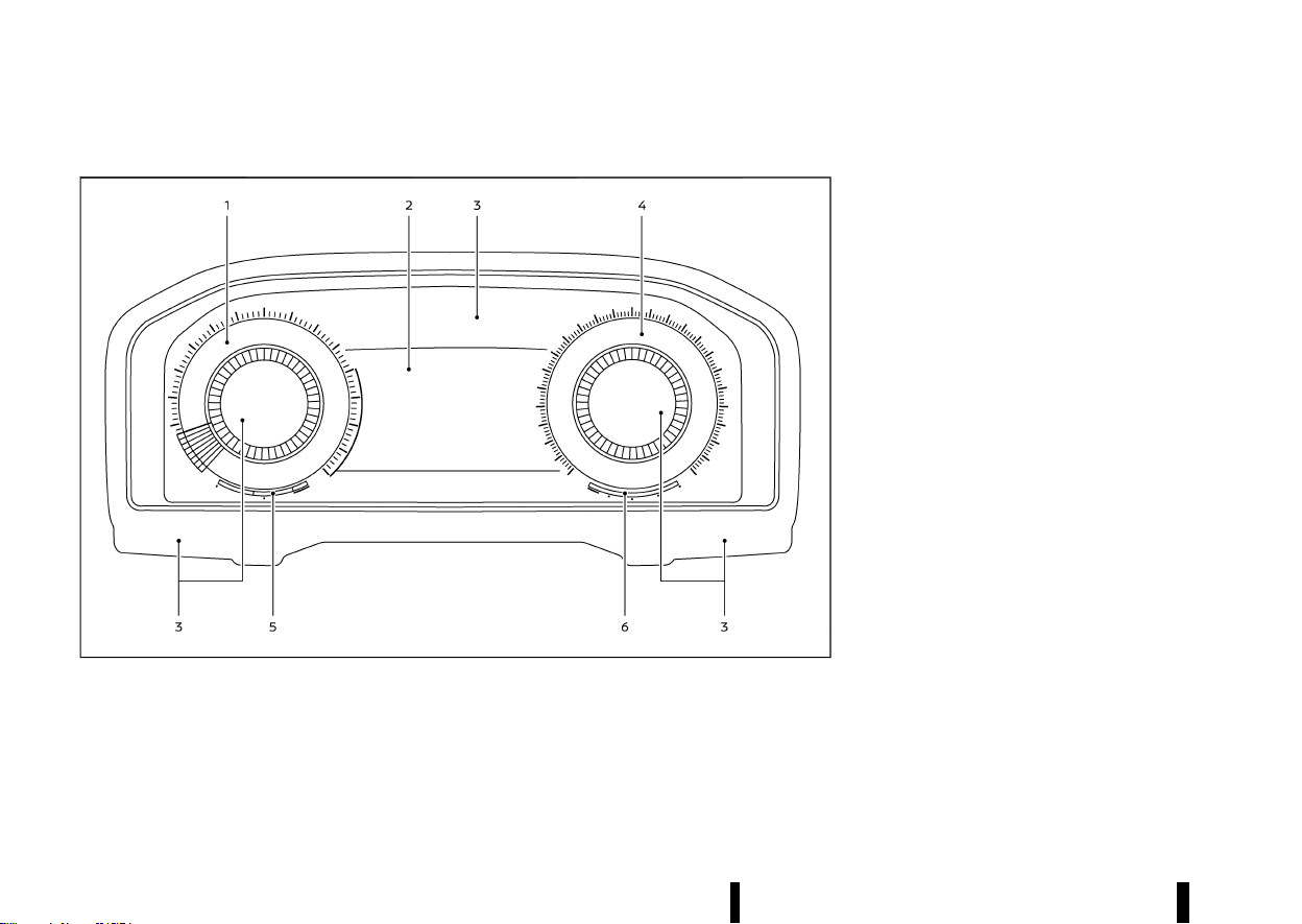
MODELS WITH FULL-SCREEN DISPLAY
MEVT33A1-A39A6527-AE0F-4CAF-AAF6-C3F27980C34F
MWAA0417X
1. Tachometer (P.70)
2. Vehicle information display (P.81)
— Odometer (P.69)
3. Warning and indicator lights (P.74)
4. Speedometer (P.69)
5. Engine coolant temperature gauge (P.70)
6. Fuel gauge (P.71)
The view of the meter screen can be changed. (See
“Changing the meter screen view (models with full-
screen display)” (P.82).)
(17,1)
MEVT33A1-8EBBE60D-ED28-4099-9931-95512256E0F1
KR15DDT ENGINE MODEL
MEVT33A1-4B962917-6178-474D-B725-E9BB6D6F3AFC
MWAA0443X
1. Engine coolant reservoir (P.428)
2. Engine oil dipstick (P.430)
3. Engine oil filler cap (P.430)
4. Brake fluid reservoir* (P.434)
5. Battery (P.437)
6. Fuse/fusible link box (P.441)
7. Intercooler coolant reservoir (P.429)
8. Window washer fluid reservoir (P.437)
9. Drive belt (P.432)
10. Air cleaner (P.435)
*: The layout illustrated is for the Left-Hand Drive
(LHD) models. On the Right-Hand Drive (RHD)
models, the brake fluid reservoir is located on the
opposite side.
Illustrated table of contents 13
ENGINE COMPARTMENT
ENGINE COMPARTMENT

(18,1)
14 Illustrated table of contents
MEMO

(19,1)
1 Safety — seats, seat belts and
supplemental restraint system
Seats ......................................................................................................................... 16
Front seats ................................................................................................ 16
Second row seats ................................................................................ 20
Third row seats (where fitted) ................................................... 23
Armrest ......................................................................................................... 24
Head restraints ................................................................................................. 25
Adjustable head restraint components ............................. 25
Non-adjustable head restraint components ................. 25
Remove ........................................................................................................ 25
Install .............................................................................................................. 26
Adjust ............................................................................................................. 26
Seat belts .............................................................................................................. 28
Precautions on seat belt usage ............................................... 28
Child safety ............................................................................................... 30
Pregnant women ................................................................................. 30
Injured persons ...................................................................................... 30
Centre mark on seat belts ............................................................ 30
Three-point type seat belts ......................................................... 31
Seat belt maintenance .................................................................... 32
Child restraints
....
............................................................................................. 33
Precautions on child restraint usage
....
............................... 33
Universal child restraints for front seat and
rear seats
....
................................................................................................ 34
ISOFIX child restraint system (for second
row seats)
....
............................................................................................... 39
Child restraint anchorage (for second row seats)
....
..... 40
Child restraint installation using ISOFIX (for second
row seats)
....
................................................................................................. 40
Child restraint installation using three-point type
seat belt
....
..................................................................................................... 42
Supplemental Restraint System (SRS)
....
......................................... 47
Precautions on Supplemental Restraint
System (SRS)
....
.......................................................................................... 47
Supplemental air bag systems
....
................................................ 52
Pre-tensioner seat belt system
....
............................................... 58
Repair and replacement procedure
....
.................................... 58
(20,1)
16 Safety — seats, seat belts and supplemental restraint system
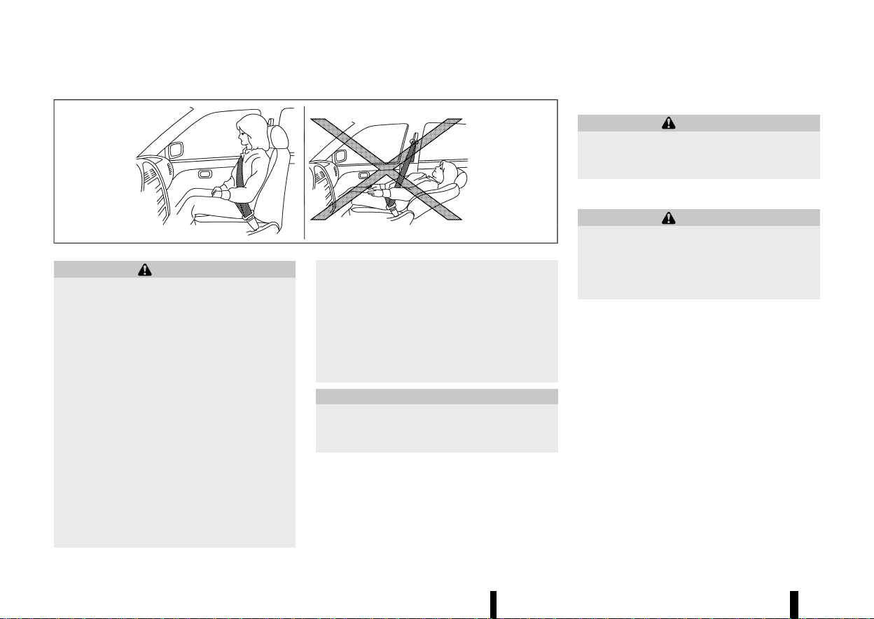
MEVT33A1-18BD8867-DE8C-4585-BEF1-DD984EC9CB4F
MSSS0133A
WARNING
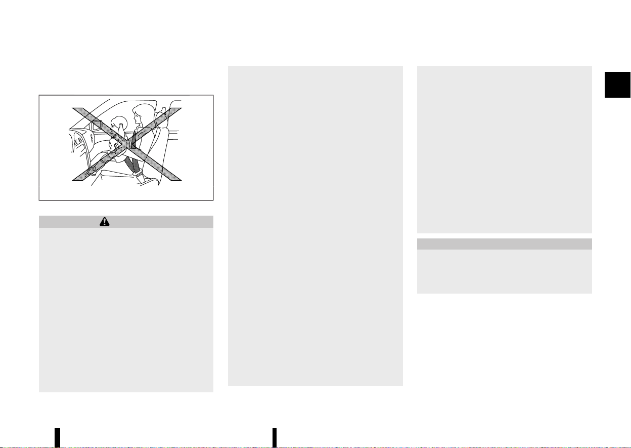
* Do not drive and/or ride in the vehicle with
the seatback reclined. This can be danger-
ous. The shoulder belt will not be properly
against the body. In an accident, you and
your passengers could be thrown into the
shoulder belt and receive neck or other
serious injuries. You and your passengers
could also slide under the lap belt and
receive serious injuries.
* For the most effective protection while the
vehicle is in motion, the seatback should
be upright. Always sit well back and up-
right in the seat and adjust the seat
properly. (See “Seat belts” (P.28).)
* Do not leave children unattended inside
the vehicle. They could unknowingly acti-
vate switches or controls. Unattended
children could become involved in serious
accidents.
* To help avoid risk of injury or death
through unintended operation of the ve-
hicle and/or its systems, do not leave
children, people who require the assis-
tance of others or pets unattended in your
vehicle. Additionally, the temperature in-
side a closed vehicle on a warm day can
quickly become high enough to cause a
significant risk of injury or death to people
and pets.
CAUTION
When adjusting the seat positions, be sure not
to contact any moving parts to avoid possible
injuries and/or damages.
FRONT SEATS
MEVT33A1-85C968F1-A418-40A7-8EBB-06AE500A830F
WARNING
Do not adjust the driver’s seat while driving so
that full attention may be given to vehicle
operation.
Manual seat adjustment
MEVT33A1-D88BFF11-C073-46C1-B896-AB43B3BB4685
WARNING
After adjusting a seat, gently shake the seat to
confirm that the seat is locked securely. If the
seat is not locked securely, it may move
suddenly and could cause the loss of control
of the vehicle.
SEATS
SEATS
(21,1)
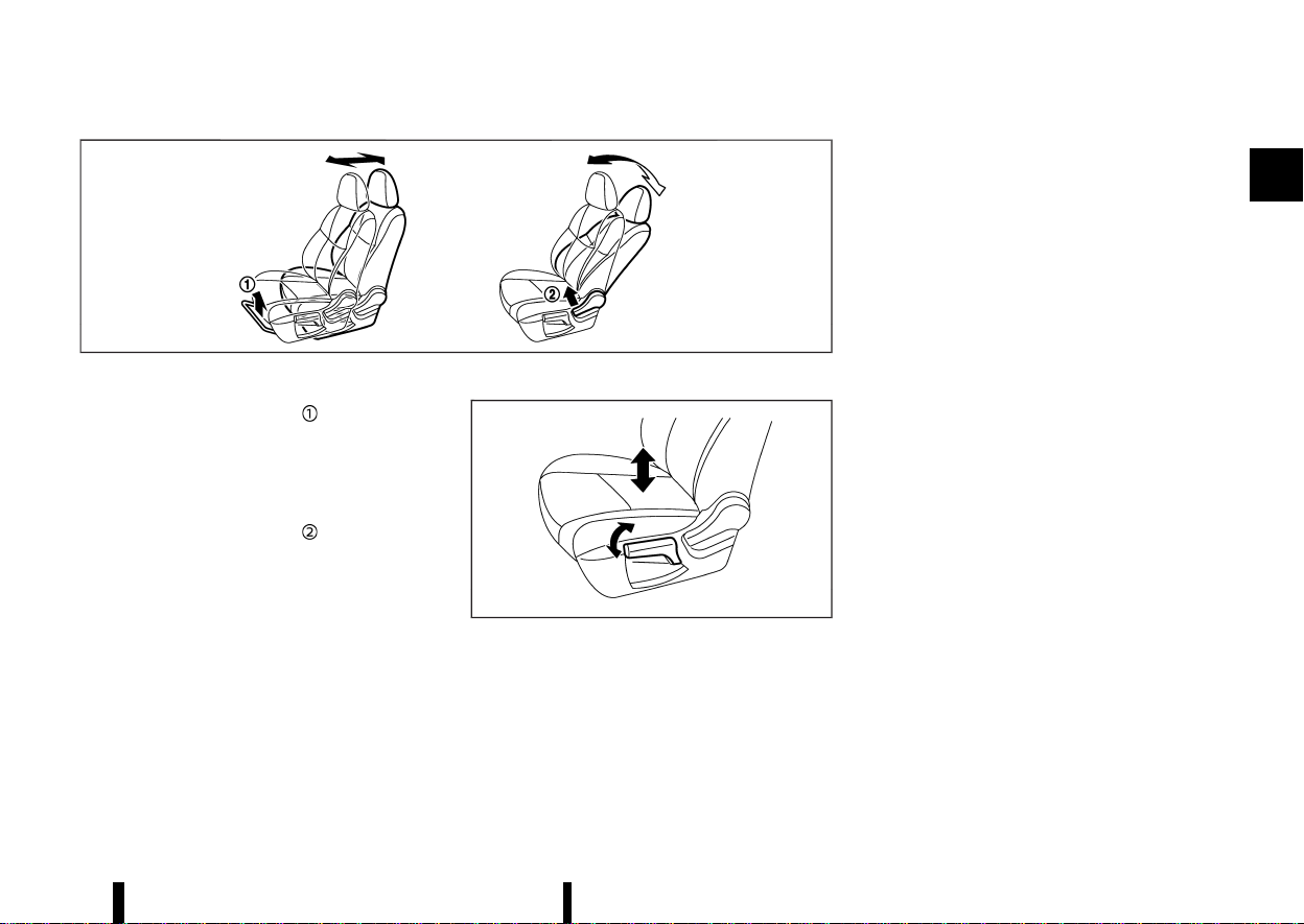
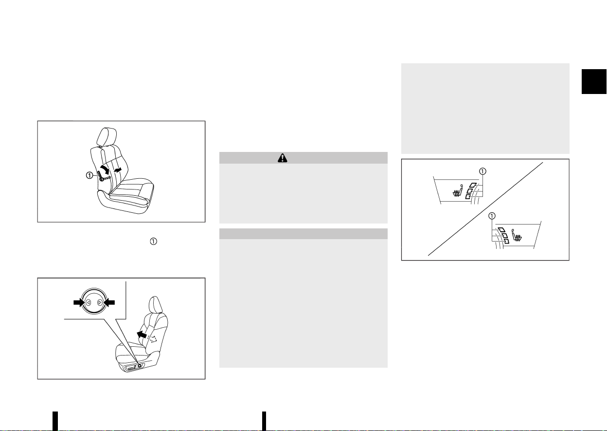
MJVR0332X
Forward and backward:
1. Pull up the adjusting lever
.
2. Slide the seat to the desired position.
3. Release the adjusting lever to lock the seat in
position.
Reclining:
1. Pull up the adjusting lever
.
2. Tilt the seatback to the desired position.
3. Release the adjusting lever to lock the seat-
back in position.
The reclining feature allows the adjustment of the
seatback for occupants of different sizes to help
obtain the proper seat belt fit. (See “Seat belts”
(P.28).)
The seatback may be reclined to allow occupants
to rest when the vehicle is parked.
Seat lifter (where fitted):
MJVR0333X
Pull up or push down the adjusting lever to adjust
the seat height until the desired position is
achieved.
Safety — seats, seat belts and supplemental restraint system 17
(22,1)
18 Safety — seats, seat belts and supplemental restraint system
Power seat adjustment
MEVT33A1-9906F271-D106-49F6-81F7-DF9101013620
Operating tips:
* The power seat motor has an auto-reset
overload protection circuit. If the motor stops
during the seat adjustment, wait 30 seconds,
then reactivate the switch.
* To avoid discharge of the battery, do not
operate the power seats for a long period of
time when the engine is not running.
See “Automatic drive positioner (where fitted)”
(P.169) for the seat position memory function.
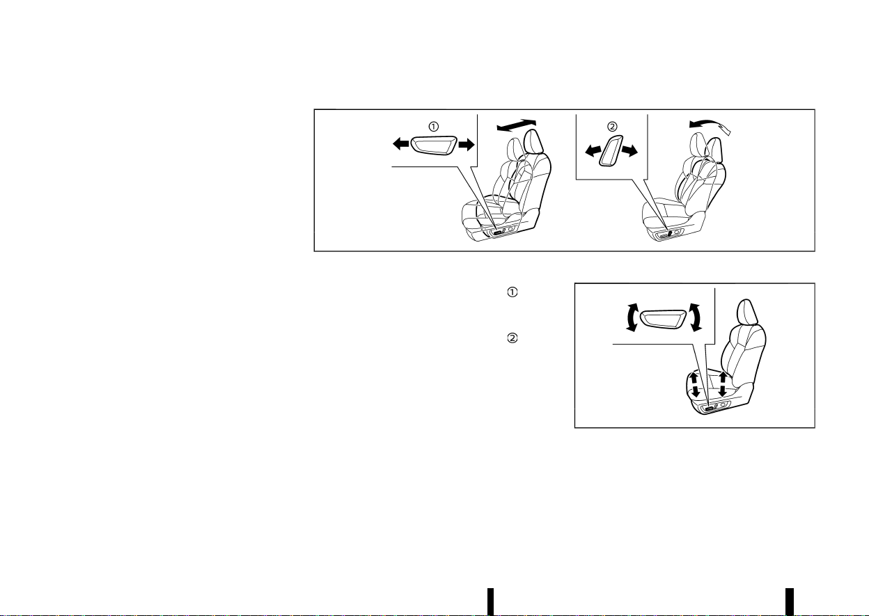
MWAB0160X
Forward and backward:
Move the adjusting switch as shown
to the
desired position.
Reclining:
Move the adjusting switch as shown
to the
desired position.
The reclining feature allows the adjustment of the
seatback for occupants of different sizes to help
obtain the proper seat belt fit. (See “Seat belts”
(P.28).)
The seatback may be reclined to allow occupants
to rest when the vehicle is parked.
Seat lifter (where fitted):
MWAB0062X
Move the switch as shown to adjust the angle of
the front portion or height of the seat.
(23,1)
Lumbar support (where fitted)
MEVT33A1-B66D18C2-4235-43A8-AE26-3B9E8214B243
The lumbar support feature provides lower back
support to the driver and front passenger (where
fitted).
Manual adjustment (where fitted):
MSSS0684
Pull or push the adjusting lever to adjust the
seat lumbar area until the desired position is
achieved.
Power adjustment (where fitted):
MWAB0063X
Push the adjusting switch as shown to adjust the
seat lumbar area until the desired position is
achieved.
NOTE:
The motor of the lumbar support will continue to
run while the switch is pushed even after full
travel in both directions is achieved.
Heated seats (where fitted)
MEVT33A1-F3A06D89-A4D5-4A04-A298-F871EB57E898
WARNING
Do not use or allow occupants to use the seat
heater if you or the occupants cannot monitor
elevated seat temperatures or have an inabil-
ity to feel pain in body parts that contact the
seat. Use of the seat heater by such people
could result in serious injury.
CAUTION
* The battery could run down if the seat
heater is operated while the engine is not
running.
* Do not use the seat heater for extended
periods or when no one is using the seat.
* Do not put anything on the seat which
insulates heat, such as a blanket, cushion,
seat cover, etc. Otherwise, the seat may
become overheated.
* Do not place anything hard or heavy on the
seat or pierce it with a pin or similar object.
This may result in damage to the heater.
* Any liquid spilled on the heated seat
should be removed immediately with a dry
cloth.
* When cleaning the seat, never use petrol,
thinner, or any similar materials.
* If any malfunctions are found or the
heated seat does not operate properly,
turn the switch off and have the system
checked by a NISSAN dealer or qualified
workshop.
MWAC0524X
The front seats are warmed by built-in heaters.
The switches are located on the instrument panel
and can be operated independently of each other.
Operation with switch:
1. Start the engine.
2. Push the heated seat switch and select the
desired heat range.
.
For high heat, push the switch once.
.
For medium heat, push the switch twice.
Safety — seats, seat belts and supplemental restraint system 19
(24,1)
20 Safety — seats, seat belts and supplemental restraint system
.
For low heat, push the switch three times.
.
The indicator light on the switch will
illuminate depending on the heat level
when the heater is on.
3. To turn off the heater, push the heated seat
switch until the indicator light turns off.
The heater is controlled by a control module,
automatically adjusting the heat level to
maintain comfort according to the selected
heat range.
The indicator light will remain on as long as
the switch is on.
When the vehicle’s interior is warmed, or
before you leave the vehicle, be sure to turn
off the seat heater.
SECOND ROW SEATS
MEVT33A1-A411A129-4112-47EF-B7F1-CEFFF02BFC50
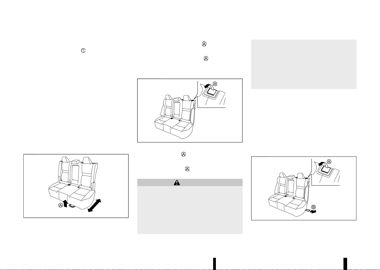
Forward and backward (where fitted)
MEVT33A1-FE35EA64-FEA2-4E0A-AB47-184C2BADA273
MWAB0338X
1. Pull up the adjusting lever .
2. Slide the seat to the desired position.
3. Release the adjusting lever
to lock the seat
in position.
Reclining
MEVT33A1-F7DD36FF-D370-42AB-860B-A7830176A8BC
MWAB0126X
1. Pull up the lever .
2. Tilt the seatback to the desired position.
3. Release the lever
to lock the seatback in
position.
WARNING
* After adjustment, gently rock in the seat to
make sure it is securely locked.
* Do not ride in a moving vehicle when the
seatback is reclined. This can be danger-
ous. The shoulder belt will not be against
your body. In an accident, you could be
thrown into it and receive neck or other
serious injuries. You could also slide under
the lap belt and receive serious internal
injuries.
* For the most effective protection when the
vehicle is in motion, the seat should be
upright. Always sit well back and upright in
the seat with both feet on the floor and
adjust the seat belt properly. (See “Precau-
tions on seat belt usage” (P.28).)
Folding
MEVT33A1-C8E913E0-3371-4FF7-8EB8-DD8BD323870A
Before folding the second row seats
* Secure the outer seat belt on the seat belt
hook. (See “Seat belt hooks” (P.32).)
* If the second row seat is equipped with the
head restraints, slide the front seat forward to
make enough room behind the seat so that
the second row seatback can be folded flat.
* Remove drink containers from the second row
cup holder.
MWAB0257X
To fold down the seatback

(25,1)
* Two row model: Pull up the lever and fold
the seatback.
* Three row model: Pull the strap
on the lower
side of the outboard seats to fold the seat-
back.
To return the seatback
To return the seatback to a seating position, raise
the seatback until it latches in place.
When returning the seatback, make sure that the
seat belts are not interfering with the seatback
latch mechanism.
WARNING
* Never allow anyone to ride in the cargo
area or on the second row seats when they
are in the fold-down position. In a collision,
people riding in these areas without prop-
er restraints are more likely to be seriously
injured or killed.
* Do not allow people to ride in any area of
your vehicle that is not equipped with
seats and seat belts. Be sure everyone in
your vehicle is in a seat and using a seat
belt properly.
* Do not allow more than one person to use
the same seat belt.
* Do not fold down the second row seats
when occupants are in the second row
seat area or any luggage is on the second
row seats.
— Make sure that the seat path is clear
before moving the seat.
— Be careful not to allow hands or feet to
get caught or pinched in the seat.
* Head restraints should be adjusted prop-
erly as they may provide significant pro-
tection against injury in an accident.
Always replace and adjust them properly
if they have been removed for any reason.
* If the head restraints are removed for any
reason, they should be securely stored to
prevent them from causing injury to pas-
sengers or damage to the vehicle in case of
sudden braking or an accident.
* When returning the seatbacks to the up-
right position, be certain they are comple-
tely secured in the latched position. If they
are not completely secured, passengers
may be injured in an accident or sudden
stop.
* Properly secure all cargo to help prevent it
from sliding or shifting. Do not place cargo
higher than the seatbacks. In a sudden
stop or collision, unsecured cargo could
cause personal injury.
Walk-in mechanism (Three row model)
MEVT33A1-3E1CA7F0-B199-43A7-A9D1-DDCC37F400B2
The second row seats can tilt and slide for easy
entry/exit to/from the third row seats.
WARNING
After operating the walk-in mechanism, be
sure to return the seat to the rearmost position
and then tilt up the seatback until it latches.
CAUTION
* When operating the walk-in mechanism,
push and hold the seatback and operate
slowly. If the seatback is tilted down
quickly and then allowed to slide, there is
a risk that it could contact your face or
other parts of your body, or pinch your
hand or foot, causing injury.
* When operating the walk-in mechanism,
be sure not to contact any moving parts to
avoid possible injuries and/or damage.
* When operating the walk-in mechanism,
be sure that the second row seats are not
occupied by passengers and/or any ob-
jects to avoid possible injuries and/or
damage.
* Do not operate the walk-in mechanism
with objects, drinks, etc. on the seat. This
may cause objects to break or cause the
passenger room to be soiled.
Safety — seats, seat belts and supplemental restraint system 21
(26,1)
22 Safety — seats, seat belts and supplemental restraint system
MJVR0355X
1. Pull the lever to tilt down the seatback.
2. Slide the seat forward.
3. When returning the seat to its original position,
slide the seat backward, tilt the seatback up
and then secure it in place.
Heated seats (where fitted)
MEVT33A1-C8AC0AF0-E61D-401A-8D64-F602F03D0C44
WARNING
Do not use or allow occupants to use the seat
heater if you or the occupants cannot monitor
elevated seat temperatures or have an inabil-
ity to feel pain in body parts that contact the
seat. Use of the seat heater by such people
could result in serious injury.
CAUTION
* The battery could run down if the seat
heater is operated while the engine is not
running.
* Do not use the seat heater for extended
periods or when no one is using the seat.
* Do not put anything on the seat which
insulates heat, such as a blanket, cushion,
seat cover, etc. Otherwise, the seat may
become overheated.
* Do not place anything hard or heavy on the
seat or pierce it with a pin or similar object.
This may result in damage to the heater.
* Any liquid spilled on the heated seat
should be removed immediately with a
dry cloth.
* When cleaning the seat, never use petrol,
thinner, or any similar materials.
* If any malfunctions are found or the
heated seat does not operate properly,
turn the switch off and have the system
checked by a NISSAN dealer or qualified
workshop.
MWAC0525X
The second row seats are warmed by built-in
heaters. The switches are located on the back of
the centre console and can be operated indepen-
dently of each other.
Operation with switch:
1. Start the engine.
2. Push the heated seat switch and select the
desired heat range.
.
For high heat, push the switch once.
.
For medium heat, push the switch twice.
.
For low heat, push the switch three times.
.
The indicator light on the switch will
illuminate depending on the heat level
when the heater is on.
3. To turn off the heater, push the heated seat
switch until the indicator light turns off.
The heater is controlled by a control module,
(27,1)
automatically adjusting the heat level to
maintain comfort according to the selected
heat range.
The indicator light will remain on as long as
the switch is on.
When the vehicle’s interior is warmed, or
before you leave the vehicle, be sure to turn
off the seat heater.
THIRD ROW SEATS (where fitted)
MEVT33A1-4C04BD90-4F26-4885-8AC5-FFDB10BAAC23
Reclining
MEVT33A1-B8B453D6-F88A-4BBC-A98A-F1FC8D2BF134
MSSS1068
Pull the strap and position the seatback at the
desired angle. Release the strap after positioning
the seat at the desired angle.
The reclining feature allows adjustment of the
seatback for occupants of different sizes to help
obtain proper seat belt fit. (See “Seat belts” (P.28).)
The seatback may also be reclined to allow
occupants to rest when the vehicle is parked.
WARNING
* Do not ride in a moving vehicle when the
seatback is reclined. This can be danger-
ous. The shoulder belt will not be against
your body. In an accident, you could be
thrown into it and receive neck or other
serious injuries. You could also slide under
the lap belt and receive serious internal
injuries.
* For the most effective protection when the
vehicle is in motion, the seat should be
upright. Always sit well back and upright in
the seat with both feet on the floor and
adjust the seat belt properly. See “Precau-
tions on seat belt usage” (P.28).
* After adjustment, check to be sure the seat
is securely locked.
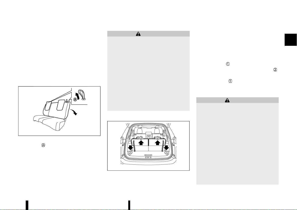
Folding
MEVT33A1-19D06334-7740-41AD-832A-B92D6BD3E2CD
MWAB0225X
Before folding the third row seats, secure the outer
seat belt on the seat belt hook. (See “Seat belt
hooks” (P.32).)
To fold the third row seats flat for maximum cargo
capacity:
1. Make sure the head restraints are all the way
down.
2. Pull the strap
to release the seat.
3. Once released, push the seatback forward
.
To return the third row seats to a seating position:
Use the pull straps
to raise each seatback. Pull
back until the seatback latches into position. Make
sure to properly raise each seatback to an upright
and secured position.
WARNING
* Never allow anyone to ride in the cargo
area or on the third row seat when it is in
the fold-down position. Use of these areas
by passengers without proper restraints
could result in serious injury in an accident
or sudden stop.
* Properly secure all cargo with ropes or
straps to help prevent it from sliding or
shifting. Do not place cargo higher than
the seatbacks. In a sudden stop or colli-
sion, unsecured cargo could cause perso-
nal injury.
* When returning the seatbacks to the up-
right position, be certain they are comple-
tely secured in the latched position. If they
are not completely secured, passengers
may be injured in an accident or sudden
stop.
Safety — seats, seat belts and supplemental restraint system 23
(28,1)
24 Safety — seats, seat belts and supplemental restraint system
* When the seat is returned to the normal
seating position, the head restraints must
be returned to the upright position to
properly protect vehicle occupants.
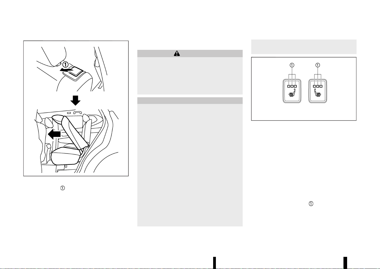
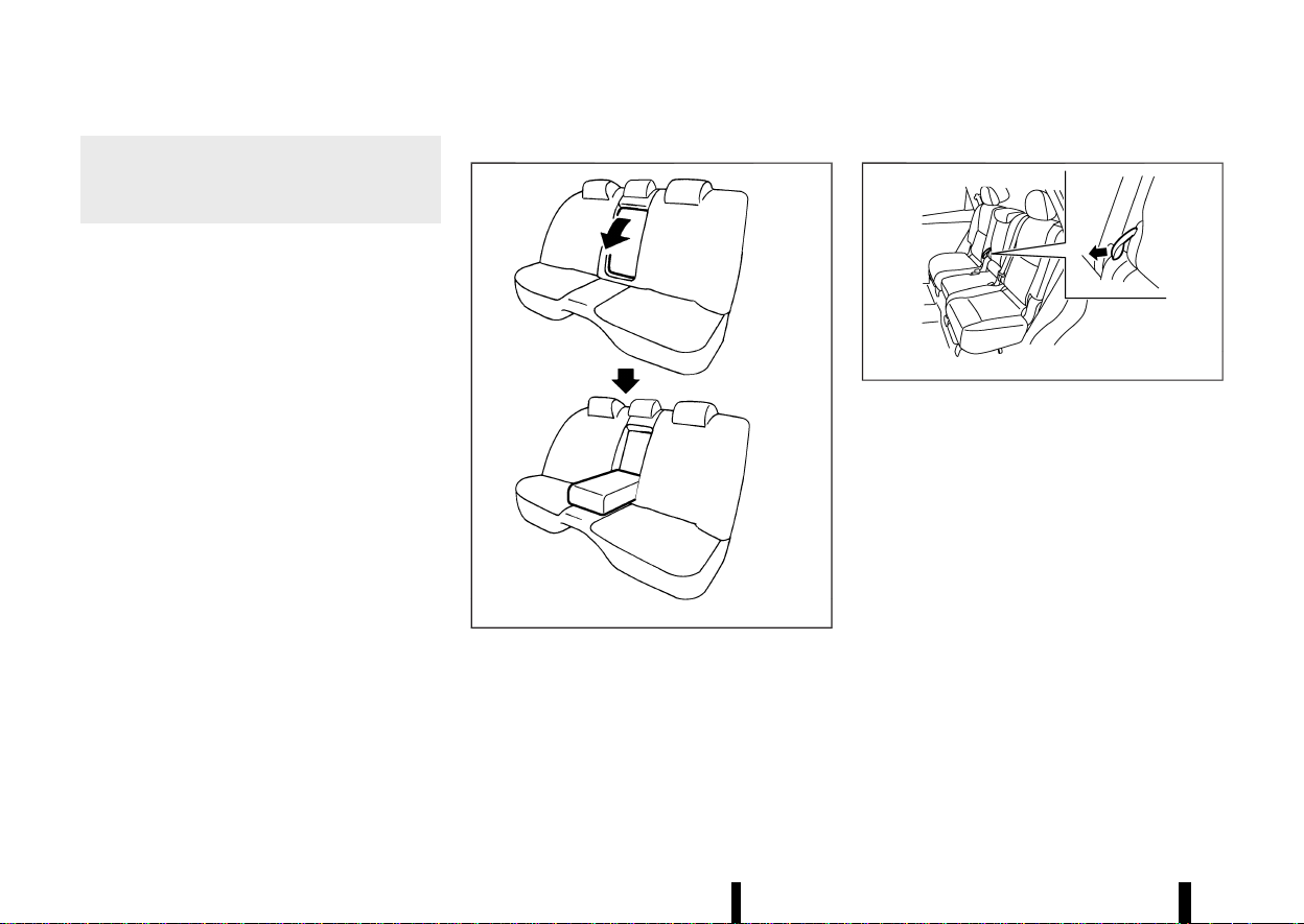
ARMREST
MEVT33A1-989199A5-A9EB-4969-8F94-26AE8B09C1CD
Second row seat
MEVT33A1-4F4938E6-FF99-49EE-8EA5-1B9BB6CEC644
The centre seatback can be folded to make the
armrest.
Two row model:
MWAB0038X
Fold down the seatback until it is horizontal.
Three row model:
MJVR0337X
Pull the strap to unlatch the seatback and fold it
down until it is horizontal.
(29,1)
MEVT33A1-9F46CC48-179E-4D38-92F3-B4FF1FEE5E49
WARNING
Head restraints supplement the other vehicle
safety systems. They may provide additional
protection against injury in certain rear end
collisions. Adjustable head restraints must be
adjusted properly, as specified in this section.
Check the adjustment after someone else uses
the seat. Do not attach anything to the head
restraint stalks or remove the head restraint.
Do not use the seat if the head restraint has
been removed. If the head restraint was
removed, reinstall and properly adjust the
head restraint before an occupant uses the
seating position. Failure to follow these in-
structions can reduce the effectiveness of the
head restraint. This may increase the risk of
serious injury or death in a collision.
* Your vehicle is equipped with a head restraint
that may be integrated, adjustable or non-
adjustable.
* Adjustable head restraints have multiple
notches along the stalk to lock them in a
desired adjustment position.
* The non-adjustable head restraints have a
single locking notch to secure them to the
seat frame.
* Proper Adjustment:
— For the adjustable type, align the head
restraint so the centre of your ear is
approximately level with the centre of the
head restraint.
— If your ear position is still higher than the
recommended alignment, place the head
restraint at the highest position.
* If the head restraint has been removed, ensure
that it is reinstalled and locked in place before
riding in that designated seating position.
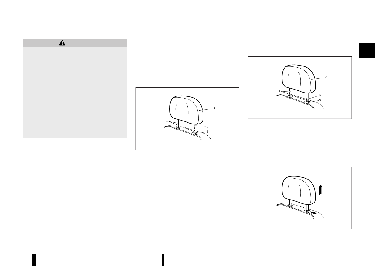
ADJUSTABLE HEAD RESTRAINT COM-
PONENTS
MEVT33A1-F3A65286-93E8-4D14-A2D5-703365D47467
MSSS0992
1. Removable head restraint
2. Multiple notches
3. Lock knob
4. Stalks
NON-ADJUSTABLE HEAD RESTRAINT
COMPONENTS
MEVT33A1-BD91B4DC-F0DE-4B8D-A4B4-92312A294B82
MJVR0203X
1. Removable head restraint
2. Single notch
3. Lock knob
4. Stalks
REMOVE
MEVT33A1-C936CA30-6028-443A-AA34-6D7719F454AF
MSSS1037
Safety — seats, seat belts and supplemental restraint system 25
HEAD RESTRAINTS
HEAD RESTRAINTS
(30,1)
26 Safety — seats, seat belts and supplemental restraint system
Use the following procedure to remove the head
restraint.
1. Pull the head restraint up to the highest
position.
2. Push and hold the lock knob.
3. Remove the head restraint from the seat.
4. Store the head restraint properly in a secure
place so it is not loose in the vehicle.
5. Reinstall and properly adjust the head re-
straint before an occupant uses the seating
position.
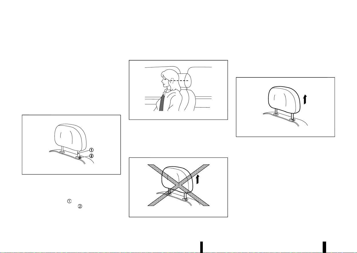
INSTALL
MEVT33A1-2CDC6030-E49D-4BE0-9201-0E4F22D499C0
MSSS1038
1. Align the head restraint stalks with the holes in
the seat. Make sure that the head restraint is
facing the correct direction. The stalk with the
adjustment notch
must be installed in the
hole with the lock knob
.
2. Push and hold the lock knob and push the
head restraint down.
3. Properly adjust the head restraint before an
occupant uses the seating position.
ADJUST
MEVT33A1-7DD10CEA-6E14-41AB-A788-7E77D9E53719
MSSS0997
For adjustable head restraint
Adjust the head restraint so the centre is level with
the centre of your ears. If your ear position is still
higher than the recommended alignment, place
the head restraint at the highest position.
MJVR0259X
For non-adjustable head restraint
Make sure the head restraint is positioned from
the stored position or any non-latch position so
the lock knob is engaged in the notch before riding
in that designated seating position.
Raise
MEVT33A1-D72E2B33-83F3-4DDF-B7E9-9F051E7ED547
MSSS1035
To raise the head restraint, pull it up.
Make sure the head restraint is positioned from
the stored position or any non-latch position so
the lock knob is engaged in the notch before riding
in that designated seating position.
(31,1)
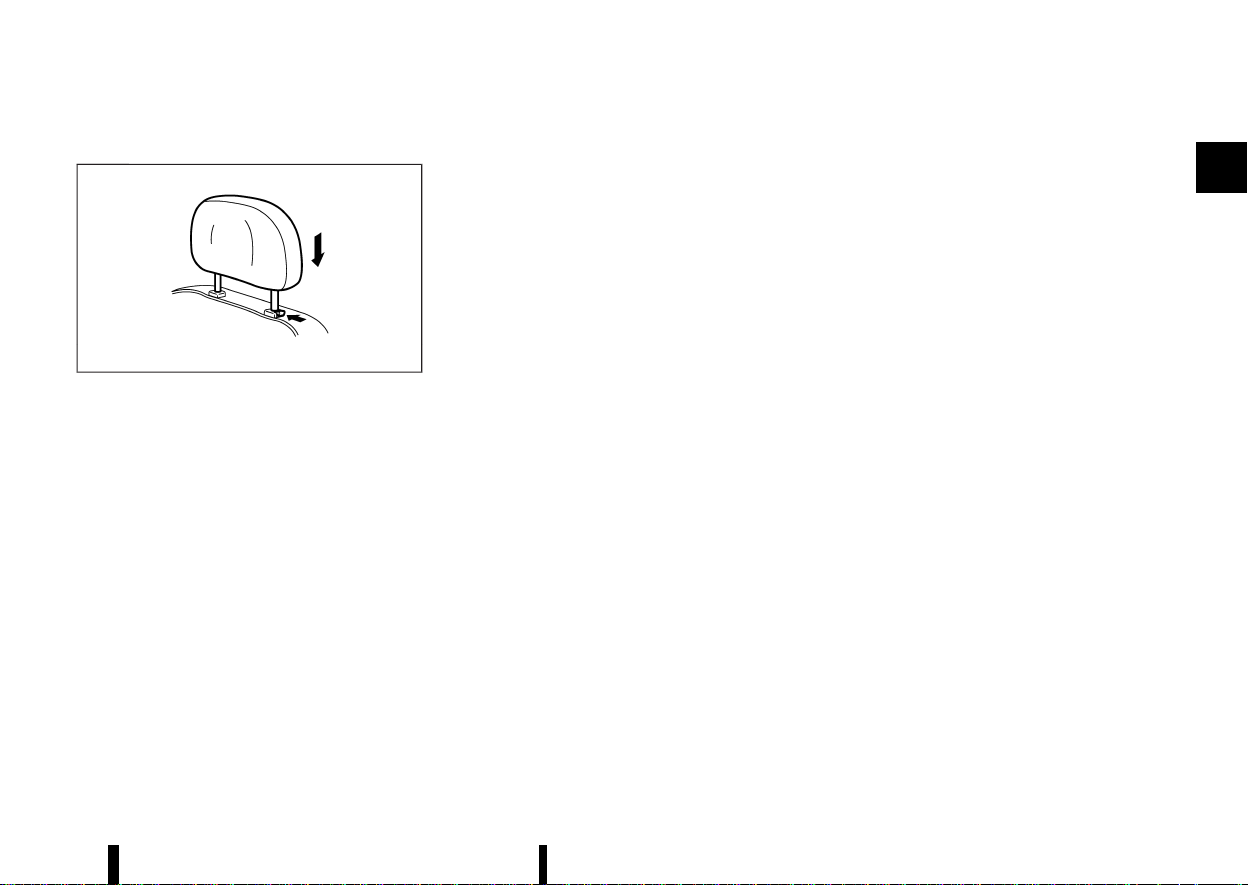
Lower
MEVT33A1-7FB30D6B-6AD8-45F4-BD51-50A7964811BF
MSSS1036
To lower, push and hold the lock knob and push
the head restraint down.
Make sure the head restraint is positioned so the
lock knob is engaged in the notch before riding in
that designated seating position.
Safety — seats, seat belts and supplemental restraint system 27
(32,1)
28 Safety — seats, seat belts and supplemental restraint system
MEVT33A1-02A01F02-FF7E-47A0-BAE4-8459B337122A
PRECAUTIONS ON SEAT BELT USAGE
MEVT33A1-0ACE675E-596A-48F6-83E5-62CAFAD8A630
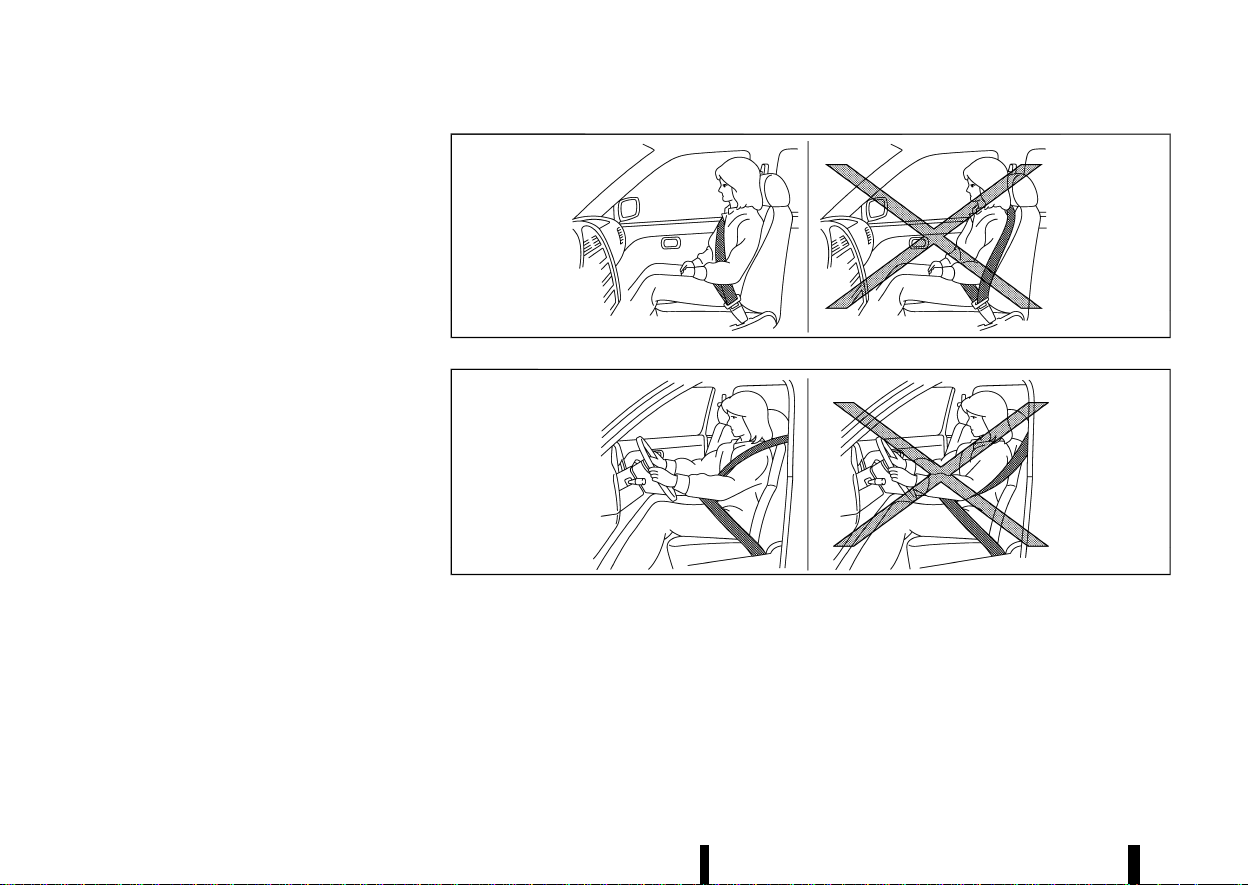
If you are wearing the seat belt properly adjusted
and sitting upright and well back in the seat,
chances of being injured or killed in an accident
and/or the severity of injury may be greatly
reduced. NISSAN strongly encourages you and all
of your passengers to buckle up every time you
drive, even if your seating position includes the
supplemental air bag systems.
MSSS0134A
MSSS0136A
SEAT BELTS
SEAT BELTS
(33,1)
MSSS0014
MSSS0016
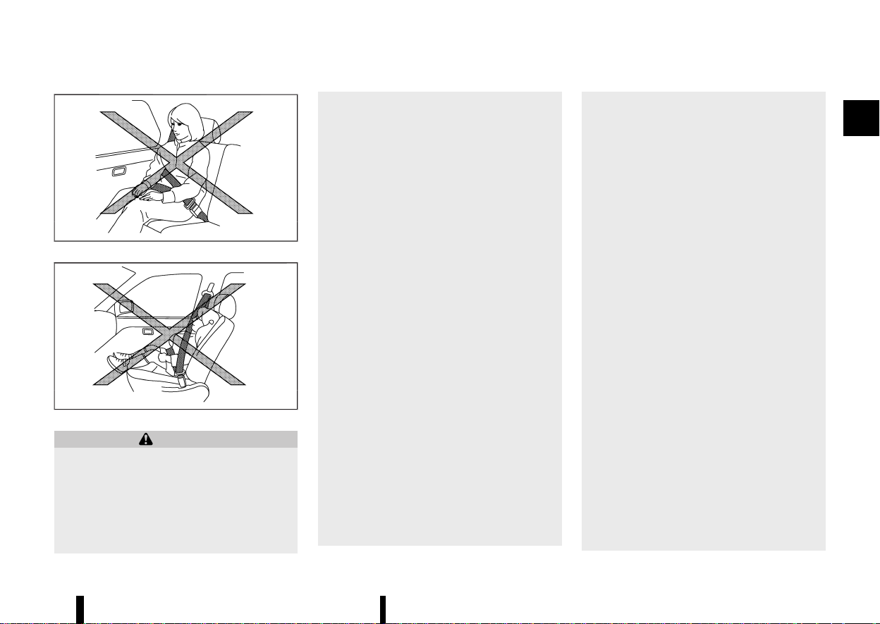
WARNING
* Seat belts are designed to bear upon the
bony structure of the body, and should be
worn low across the front of the pelvis or
the pelvis, chest and shoulders, as applic-
able; wearing the lap section of the belt
across the abdominal area must be
avoided. Serious injury may occur if a seat
belt is not worn properly.
* Position the lap belt as low and snug as
possible around the hips, not the waist. A
lap belt worn too high could increase the
risk of internal injuries in an accident.
* Do not allow more than one person to use
the same seat belt. Each belt assembly
must only be used by one occupant; it is
dangerous to put a belt around a child
being carried on the occupant’s lap.
* Never carry more people in the vehicle
than there are seat belts.
* Never wear seat belts inside out. Belts
should not be worn with straps twisted.
Doing so may reduce their effectiveness.
* Seat belts should be adjusted as firmly as
possible, consistent with comfort, to pro-
vide the protection for which they have
been designed. A slack belt will greatly
reduce the protection afforded to the
wearer.
* Every person who drives or rides in this
vehicle should use a seat belt at all times.
Children should be properly restrained in
the rear seat and, if appropriate, in a child
restraint system.
* Do not put the belt behind your back or
under your arm. Always route the shoulder
belt over your shoulder and across your
chest. The belt should be away from your
face and neck, but not falling off your
shoulder. Serious injury may occur if a seat
belt is not worn properly.
* No modifications or additions should be
made by the user which will either prevent
the seat belt adjusting devices from oper-
ating to remove slack, or prevent the seat
belt assembly from being adjusted to
remove slack.
* Care should be taken to avoid contamina-
tion of the webbing with polishes, oils and
chemicals, and particularly battery acid.
Cleaning may safely be carried out using
mild soap and water. The belt should be
replaced if webbing becomes frayed, con-
taminated or damaged.
* All seat belt assemblies including retrac-
tors and attaching hardware should be
inspected after any collision by a NISSAN
dealer or qualified workshop. NISSAN re-
commends that all seat belt assemblies in
use during a collision be replaced unless
the collision was minor and the belts show
no damage and continue to operate prop-
erly. Seat belt assemblies not in use during
a collision should also be inspected and,
when necessary, replaced if either damage
or improper operation is noted.
* It is essential to replace the entire assem-
bly after it has been worn in a severe
impact even if damage to the assembly is
not obvious.
* Once the pre-tensioner seat belt has acti-
vated, it cannot be reused. It must be
replaced together with the retractor. Con-
tact a NISSAN dealer or qualified work-
shop.
* Removal and installation of the pre-ten-
Safety — seats, seat belts and supplemental restraint system 29

(34,1)
30 Safety — seats, seat belts and supplemental restraint system
sioner seat belt system components
should be done by a NISSAN dealer or
qualified workshop.
CHILD SAFETY
MEVT33A1-B5648D61-1516-415B-9FF4-2BFA4FC7CD59
WARNING
* Infants and children need special protec-
tion. The vehicle’s seat belts may not fit
them properly. The shoulder belt may
come too close to the face or neck. The
lap belt may not fit over their small
hipbones. In an accident, an improperly
fitted seat belt could cause serious or fatal
injury.
* Always use an appropriate child restraint
system.
Children need adults to help protect them. They
need to be properly restrained. The proper re-
straint depends on the child’s size.
Infants and small children
MEVT33A1-DF6A9362-8675-4179-AF50-A58D9E8B014F
MSSS0099
NISSAN recommends that infants and small chil-
dren be seated in a child restraint system. You
should choose a child restraint system that fits
your vehicle and the child, and always follow the
manufacturer’s instructions for installation and
use.
Large children
MEVT33A1-067AF272-0DC0-4EFD-94BE-8AC648273899
WARNING
* Never allow children to stand or kneel on
any seats.
* Never allow children in the cargo areas
while the vehicle is moving. A child could
be seriously injured in an accident or
sudden stop.
Children who are too large for a child restraint
system should be seated and restrained by the
seat belts that are provided.
If the child’s seating position has a shoulder belt
that fits close to the face or neck, the use of a
booster seat (commercially available) may help
overcome this. The booster seat should raise the
child so that the shoulder belt is properly posi-
tioned across the top, middle portion of the
shoulder and the lap belt is low on the hips. The
booster seat should also fit the vehicle seat. Once
the child has grown so that the shoulder belt is no
longer on or near the face or neck of the child, use
the shoulder belt without the booster seat. In
addition, there are many types of child restraint
systems available for larger children that should be
used for maximum protection.
PREGNANT WOMEN
MEVT33A1-8535DF19-E4B9-4E3F-B551-D63E7FD8DAD4
NISSAN recommends that pregnant women use
seat belts. The seat belt should be worn snug, and
always position the lap belt as low as possible
around the hips, not the waist. Place the shoulder
belt over your shoulder and across your chest.
Never put the lap/shoulder belt over your abdom-
inal area. Contact your doctor for specific recom-
mendations.
INJURED PERSONS
MEVT33A1-CDE57920-066D-4D92-8F4B-61FBBC88D6FD
NISSAN recommends that injured persons use seat
belts. Contact your doctor for specific recommen-
dations.
CENTRE MARK ON SEAT BELTS
MEVT33A1-57A582CC-0CDE-4B48-87D9-BDB5FB699519
Selecting correct set of seat belts
MEVT33A1-F2530D75-E5EC-47BC-A377-E96B24C3957D
MWAB0267X
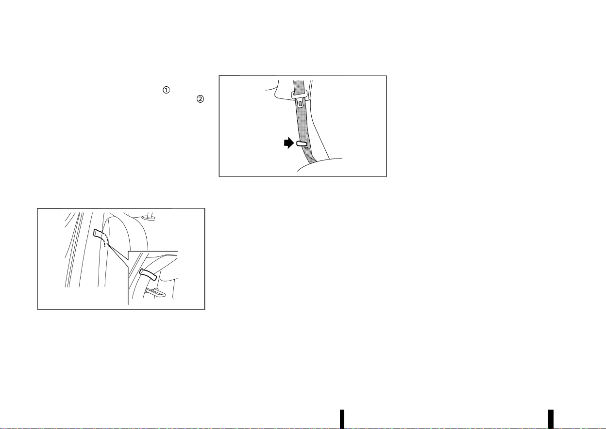
The centre seat belt buckle is identified by the
CENTER mark. The centre seat belt tongue can be
fastened only into the centre seat belt buckle.
(35,1)
THREE-POINT TYPE SEAT BELTS
MEVT33A1-E90D906F-7179-483F-A8CE-2939112EA9C1
MSSS0292
WARNING
Every person who drives or rides in this vehicle
should use a seat belt at all times.
Fastening seat belts
MEVT33A1-C84F842D-6816-45B0-82BC-0F755E0DFEAC
WARNING
The seatback should not be in a reclined
position any more than needed for comfort.
Seat belts are most effective when the pas-
senger sits well back and straight up in the
seat.
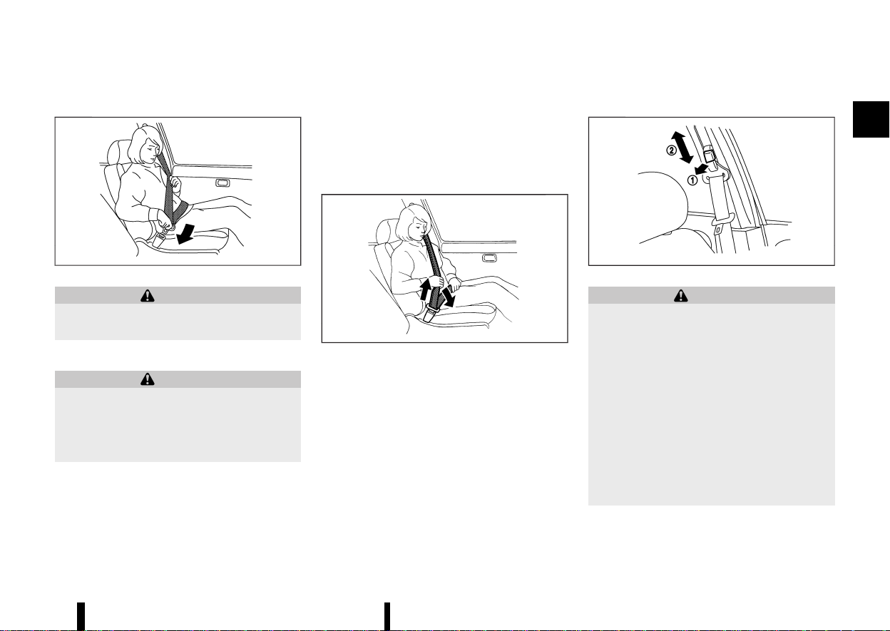
1. Adjust the seat. (See “Seats” (P.16).)
2. Slowly pull the seat belt out of the retractor
and insert the tongue into the buckle until you
hear and feel the latch engage.
.
The retractor is designed to lock during a
sudden stop or on impact. A slow pulling
motion permits the seat belt to move, and
allows you some freedom of movement
in the seat.
.
If the seat belt cannot be pulled from its
fully retracted position, firmly pull the belt
and release it. Then smoothly pull the belt
out of the retractor.
MSSS0467
3. Position the lap belt portion low and snug on
the hips as shown.
4. Pull the shoulder belt portion toward the
retractor to take up extra slack. Be sure the
shoulder belt is routed over your shoulder and
is snug across your chest.
Shoulder belt height adjustment (for front seats)
MEVT33A1-DB4FA7E4-7AFB-40A5-998A-C87D450CC231
MSSS0351A
WARNING
* The shoulder belt anchor height should be
adjusted to the position best for you.
Failure to do so may reduce the effective-
ness of the entire restraint system and
increase the chance or severity of injury in
an accident.
* The shoulder belt should rest on the
middle of the shoulder. It must not rest
against the neck.
* Be sure that the seat belt is not twisted in
any way.
* Be sure that the shoulder belt anchor is
secured by trying to move the shoulder
belt anchor up and down after adjustment.
The shoulder belt anchor height should be ad-
justed to the position best for you.
Safety — seats, seat belts and supplemental restraint system 31
(36,1)
32 Safety — seats, seat belts and supplemental restraint system
The belt should be away from your face and neck,
but not falling off your shoulder.
To adjust, pull out the release button
and move
the shoulder belt anchor to the proper position
,
so that the belt passes over the centre of the
shoulder.
Release the button to lock the shoulder belt
anchor into position.
Unfastening seat belts
MEVT33A1-6B2FCB5C-0ECC-4CC5-85C2-56DC96048B32
Push the button on the buckle. The seat belt
automatically retracts.
Seat belt hooks
MEVT33A1-E3C1A8D5-38FB-4BD3-BCD0-63B489A2E02A
Second row seat:
MWAB0084X
When folding down the second row seats, hook
the second row outer seat belts on the seat belt
hooks.
Third row seat (where fitted):
MSSS1076
When folding down the third row seats, hook the
third row seat belts on the seat belt hooks.
Checking seat belt operation
MEVT33A1-8A88E1D7-0503-491C-8881-957627E5AE03
Seat belt retractors are designed to lock seat belt
movement:
* When the seat belt is pulled quickly from the
retractor.
* When the vehicle slows down rapidly.
To increase your confidence in the seat belts,
check the operation by grasping the shoulder belt
and pulling forward quickly. The retractor should
lock and restrict further belt movement. If the
retractor does not lock during this check, contact
a NISSAN dealer or qualified workshop immedi-
ately.
SEAT BELT MAINTENANCE
MEVT33A1-7F37C59E-8849-4E54-AB60-A70E8CF21156
Periodically check that the seat belt and all the
metal components, such as buckles, tongues,
retractors, flexible wires and anchors, work prop-
erly. If loose parts, deterioration, cuts or other
damage on the seat belt webbing is found, the
entire seat belt assembly should be replaced.
If dirt builds up in the shoulder belt guide of the
seat belt anchors, the seat belts may retract
slowly. Wipe the shoulder belt guide with a clean,
dry cloth.
To clean the seat belt webbing, apply a mild soap
solution or any solution recommended for clean-
ing upholstery or carpet. Then wipe with a cloth
and allow the seat belts to dry in the shade. Do not
allow the seat belts to retract until they are
completely dry.
(37,1)
MEVT33A1-40095FB4-959D-40CC-8C8C-A53C651F2481
PRECAUTIONS ON CHILD RESTRAINT
USAGE
MEVT33A1-008AB0E5-0DF0-477B-8A23-DE796F025B15
MSSS0099
WARNING
* Infants and small children should always
be placed in an appropriate child restraint
while riding in the vehicle. Failure to use a
child restraint can result in serious injury
or death.
* Infants and small children should never be
carried on your lap. It is not possible for
even the strongest adult to resist the
forces of a severe accident. The child could
be crushed between the adult and parts of
the vehicle. Also, do not put the same seat
belt around both your child and yourself.
* NISSAN recommends that the child re-
straints be installed in the rear seat.
According to accident statistics, children
are safer when properly restrained in the
rear seat than in the front seat.
* Improper use or improper installation of a
child restraint can increase the risk or
severity of injury for both the child and
other occupants of the vehicle and can
lead to serious injury or death in an
accident.
* Follow all of the child restraint manufac-
turer’s instructions for installation and use.
When purchasing a child restraint, be sure
to select one which will fit your child and
vehicle. It may not be possible to properly
install some types of child restraint in your
vehicle.
* The direction of the child restraint, either
front-facing or rear-facing, depends on the
type of the child restraint and the size of
the child. Refer to the child restraint
manufacturer’s instructions for details.
* After attaching a child restraint, test it
before you place the child in it. Push it
from side to side and tug it forward to
make sure that it is held securely in place.
The child restraint should not move more
than 25 mm (1 in). If the restraint is not
secure, tighten the belt as necessary, or
install the restraint in another seat and
test it again.
* When the child restraint is not in use, keep
it secured with the ISOFIX child restraint
system or a seat belt to prevent it from
being thrown around in case of a sudden
stop or accident.
* Adjustable seatbacks should be positioned
to ensure full contact between child re-
straint and seatback.
* Never install a rear-facing child restraint
on the front passenger seat without en-
suring that the supplemental front pas-
senger air bag is deactivated.
Supplemental front-impact air bags inflate
with great force. A rear-facing child re-
straint could be struck by the supplemen-
tal front-impact air bags in an accident
and could seriously injure or kill your child.
* If the seat belt in the position where a child
restraint is installed requires a locking
device and if it is not used, injuries could
result from a child restraint tipping over
during normal vehicle braking or corner-
ing.
CAUTION
Remember that a child restraint left in a closed
vehicle can become very hot. Check the seat-
ing surface and buckles before placing your
child in a child restraint.
NISSAN recommends that infants and small chil-
dren be seated in a child restraint. You should
choose a child restraint that fits your vehicle and
always follow the manufacturer’s instructions for
installation and use. In addition, there are many
types of child restraints available for larger chil-
dren that should be used for maximum protection.
Safety — seats, seat belts and supplemental restraint system 33
CHILD RESTRAINTS
CHILD RESTRAINTS
(38,1)
34 Safety — seats, seat belts and supplemental restraint system
UNIVERSAL CHILD RESTRAINTS FOR
FRONT SEAT AND REAR SEATS
MEVT33A1-A45AF694-FFA0-4831-BE2D-79927081167D
NOTE:
Universal child restraints approved to UN Reg-
ulation No.44 (UN R44) or UN Regulation No. 129
(UN R129) are clearly marked "Universal".
When selecting any child restraint, keep the
following points in mind:
* Choose a child restraint that complies with the
UN R44 or UN R129.
* Place your child in the child restraint and
check the various adjustments to be sure the
child restraint is compatible with your child.
Always follow all of the recommended proce-
dures.
* Check the child restraint in your vehicle to be
sure it is compatible with vehicle’s seat belt
system.
* Refer to the tables later in this section for a list
of the recommended fitment positions and
the approved child restraints for your vehicle.
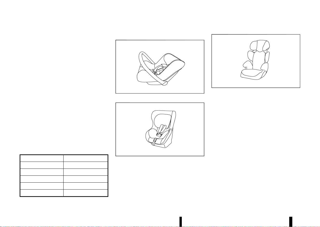
Mass group of child seat
MEVT33A1-52316865-9C95-4DA9-BAE6-C26EAC3443D9
Mass group Child’s weight
Group 0 up to 10 kg
Group 0+ up to 13 kg
Group I 9 to 18 kg
Group II 15 to 25 kg
Group III 22 to 36 kg
Kind of child seats (example):
MJVR0371X
Child safety seat categories 0 and 0+
MJVR0372X
Child safety seat categories 0+ and I
MJVR0373X
Child safety seat categories II and III
(39,1)
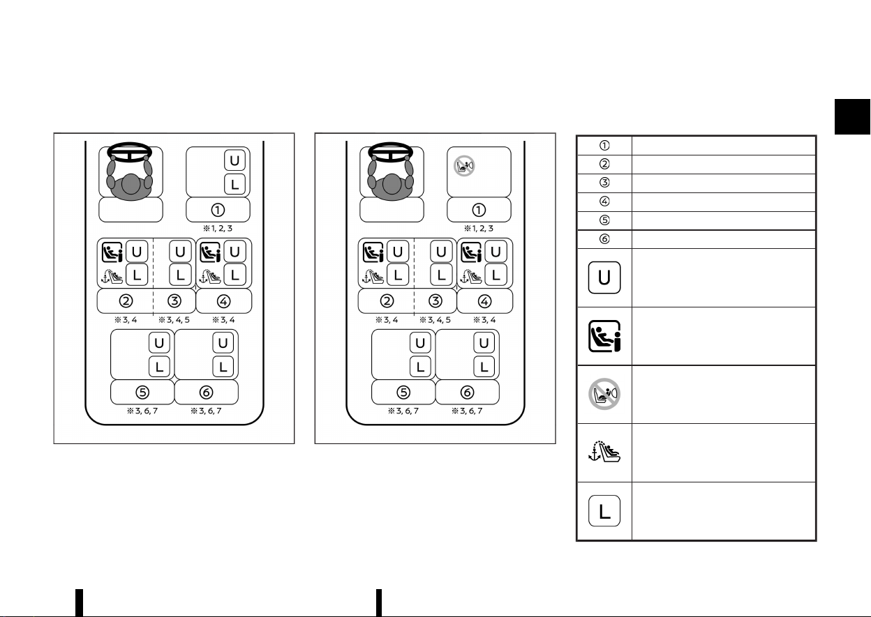
Selecting the child restraint system for each seating position
MEVT33A1-55508152-20F8-4BE8-9508-C65466D2AFD4
A child restraint system that can be used differs according to the seating position.
MWAB0345X
<PASSENGER AIR BAG OFF> indicator illuminated
MWAB0346X
<PASSENGER AIR BAG ON> indicator illuminated
Front passenger seat
Row 2: left hand outboard seat
Row 2: centre seat
Row 2: right hand outboard seat
Row 3: left seat (for three row model)
Row 3: right seat (for three row model)
MWB-
B0002X
Suitable for child safety seats that are
fixed with vehicle seat belt
MWB-
B0034X
Suitable for i-Size child safety seats
MWB-
B0044X
Prohibit installation of rearward facing
child restraint system
MWB-
B0004X
Seats equipped with top tether anchor
MWB-
B0035X
Suitable for child safety seats listed in
the attached list
Safety — seats, seat belts and supplemental restraint system 35

(40,1)
36 Safety — seats, seat belts and supplemental restraint system
*1: Adjust the seat slide to the rearmost posi-
tion.
*2: Adjust the seat lifter (where fitted) to the
uppermost position.
*3: Move the head restraint to the uppermost
position or remove it (and store securely) if
there is any interference with the child
restraint. Do not remove head restraint when
using a booster cushion only.
*4: Adjust the front seat slide to the centre
position.
*5: Do not install child restraints with a support
leg.
*6: Adjust the second seat slide to the front
most position.
*7: Adjust the second seat backrest to the first
locking position.
(41,1)
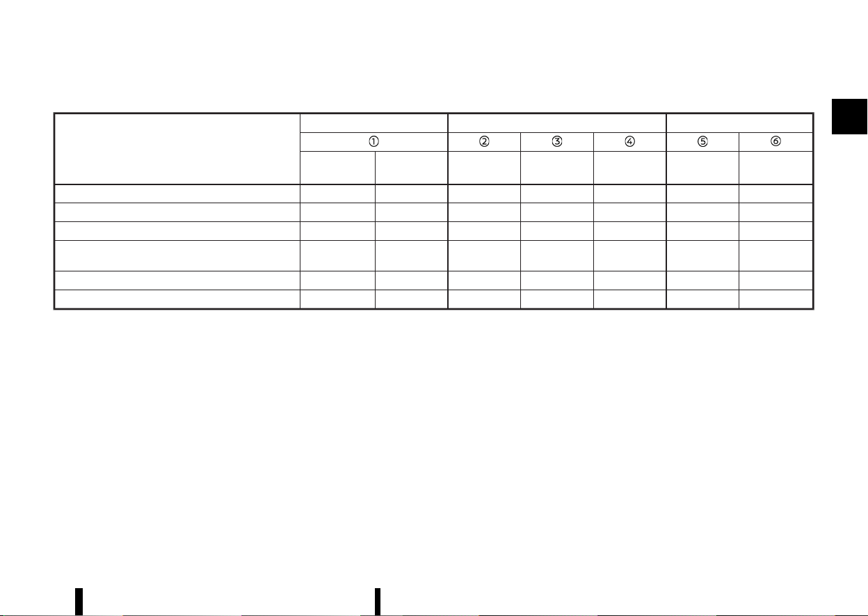
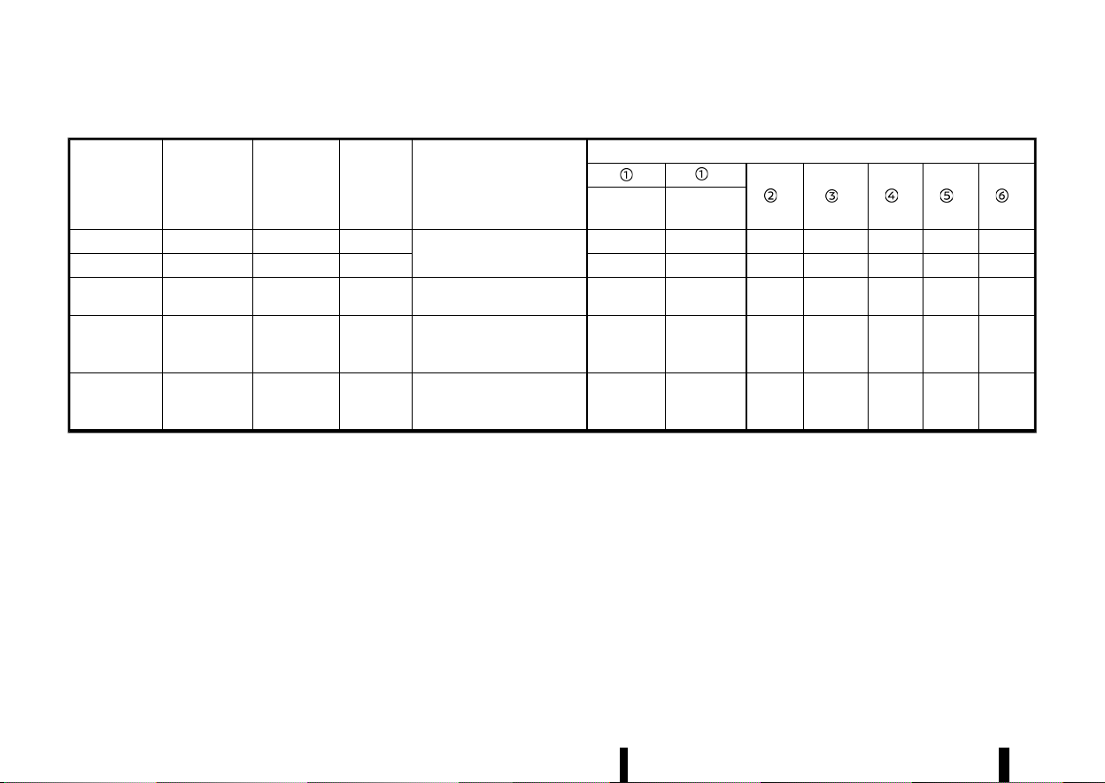
Detailed information for child restraint system installation:
Seat position number
Front Second row
Third row
Air Bag
Activation
Air Bag
Deactivation
Left Centre Right Left
Right
Seating position suitable for universal belted (Yes/No) No Yes Yes Yes Yes Yes
Yes
i-Size seating position (Yes/No) No No Yes No Yes No
No
Seating position suitable for lateral fixture (L1/L2) — — — — — —
—
Largest suitable rearward facing fixture (R1/R2X/R2/
R3)
— — R3 — R3 —
—
Largest suitable forward facing fixture (F2X/F2/F3) — — F3 — F3 —
—
Largest suitable booster fixture (B2/B3) — — B3 — B3 —
—
Safety — seats, seat belts and supplemental restraint system 37
(42,1)
38 Safety — seats, seat belts and supplemental restraint system
List of recommended child restraints:
Age
(approx.)
Weight
(approx.)
Height
(approx.)
CRS Mass
Category
Recommend CRS
CRS suitable seat position
**
** ** ** **
**
Air bag
Activation
Air bag
Deactivation
0 - 12 months Up to 10 kg < 75 cm 0
Maxi Cosi 2way Pearl +
2wayFix Base
No No Yes No Yes No
No
0 - 18 months Up to 13 kg < 85 cm 0+ No No Yes No Yes No
No
9 months - 4
years old
9 - 18 kg 76 - 105 cm I Britax Römer Trifix 2 i-Size No No Yes No Yes No
No
4 - 6 years old 15 - 25 kg 100 - 125 cm II Britax Römer Kidfix i-Size* No
Yes
(Belt only)
Yes
Yes
(Belt only)
Yes
Yes
(Belt
only)
Yes
(Belt
only)
6 - 10 years old 22 - 36 kg > 125 cm III Britax Römer Kidfix i-Size* No
Yes
(Belt only)
Yes
Yes
(Belt only)
Yes
Yes
(Belt
only)
Yes
(Belt
only)
* It is recommended to use the lap belt Secure Guard, SICT and XP-Pad when using the Kidfix i-Size.
** Move the head restraint to the uppermost position or remove it (and store securely) if there is any interference with the child restraint. Do not remove head
restraint when using a booster cushion only.
(43,1)
ISOFIX CHILD RESTRAINT SYSTEM (for
second row seats)
MEVT33A1-80F0EFB1-A98F-486F-B723-0BADA5924973
Your vehicle is equipped with special anchor points
that are used with ISOFIX child restraint systems.
ISOFIX lower anchor point locations
MEVT33A1-C5497A1C-22ED-473A-A672-E6A8E5EEE048
The ISOFIX anchor points are provided to install
child restraints in the second row outboard seat-
ing positions only. Do not attempt to install a
child restraint in the centre position using the
ISOFIX anchors.
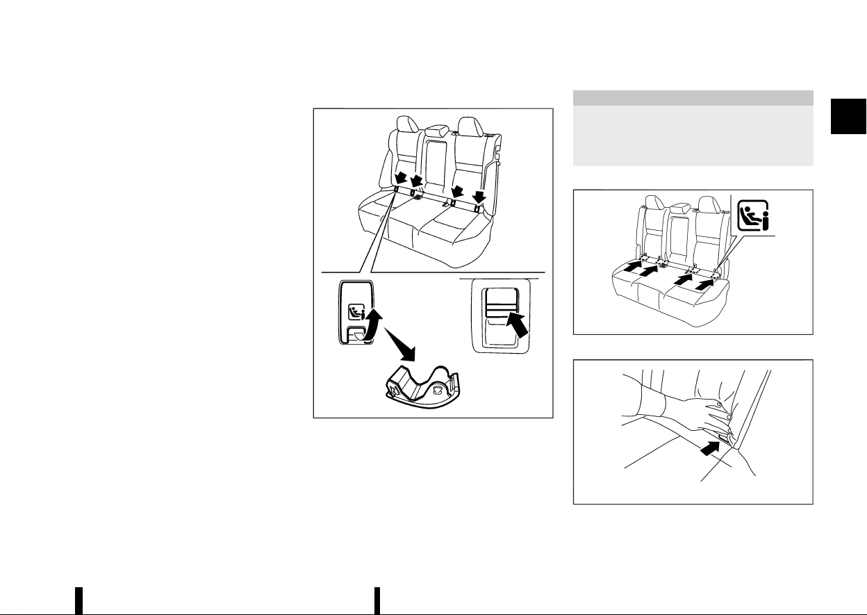
Type A:
MWAB0344X
The ISOFIX lower anchor points are located under
covers labelled ISOFIX at the bottom of the rear
seat cushions. To access a ISOFIX lower anchor
point, insert your finger into the cover and pull the
cover off.
CAUTION
Store the loose ISOFIX covers (for example, in
the console box) where they will not get
damaged to avoid losing them. (See “Console
box” (P.128).)
Type B:
MWAB0326X
ISOFIX label location
MSSS0637
ISOFIX lower anchor location
The ISOFIX anchors are located at the rear of the
Safety — seats, seat belts and supplemental restraint system 39
(44,1)
40 Safety — seats, seat belts and supplemental restraint system
seat cushion near the seatback. A label is attached
to the seatback to help you locate the ISOFIX
anchors.
ISOFIX child restraint anchor attachments
MEVT33A1-A537A246-8345-49B4-A12E-7D8DFF3A3757
MSSS0644
Anchor attachment
ISOFIX child restraints include two rigid attach-
ments that can be connected to two anchors
located in the seat. With this system, you do not
have to use a vehicle seat belt to secure the child
restraint. Check your child restraint for a label
stating that it is compatible with the ISOFIX child
restraints. This information may also be in the
instructions provided by the child restraint manu-
facturer.
ISOFIX child restraints generally require the use of
a top tether strap or other anti-rotation devices
such as support legs. When installing ISOFIX child
restraints, carefully read and follow the instruc-
tions in this manual and those supplied with the
child restraints. (See “Child restraint installation
using ISOFIX (for second row seats)” (P.40).)
CHILD RESTRAINT ANCHORAGE (for
second row seats)
MEVT33A1-3CF58FA0-110F-48B6-BD3E-0AA5FB83E437
Your vehicle is designed to accommodate a child
restraint system on the second row seat. When
installing a child restraint system, carefully read
and follow the instructions in this manual and
those supplied with the child restraint system.
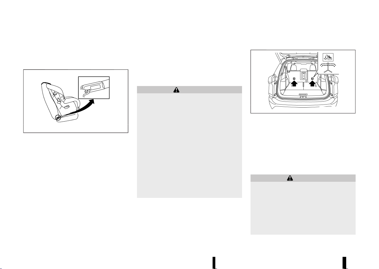
WARNING
* Child restraint anchorages are designed to
withstand only those loads imposed by
correctly fitted child restraints. Under no
circumstances are they to be used for
adult seat belts, harnesses or for attaching
other items or equipment to the vehicle.
Doing so could damage the child restraint
anchorages. The child restraint will not be
properly installed using the damaged an-
chorage, and a child could be seriously
injured or killed in a collision.
* The child restraint top tether strap may be
damaged by contact with the tonneau
cover or items in the luggage area. Re-
move the tonneau cover from the vehicle
or secure it and any luggage. Your child
could be seriously injured or killed in a
collision if the top tether strap is damaged.
Anchorage location
MEVT33A1-34D2E2A2-A0AB-483B-9974-1D7751B4E0E5
MWAB0233X
Anchorages are located as illustrated. Position the
top tether strap over the top of the seatback and
secure it to the tether anchorage that provides the
straightest installation. Tighten the tether strap
according to the manufacturer’s instruction to
remove any slack.
CHILD RESTRAINT INSTALLATION USING
ISOFIX (for second row seats)
MEVT33A1-EC610055-99A2-4018-9558-F293B2A8A7E9
WARNING
* Attach ISOFIX child restraints only at the
specified locations. For the ISOFIX lower
anchor locations, see “ISOFIX child re-
straint system (for second row seats)”
(P.39). If a child restraint is not secured
properly, your child could be seriously
injured or killed in an accident.
* Do not install child restraints that require
the use of a top tether strap to seating
(45,1)
positions that do not have a top tether
anchor.
* Do not secure a child restraint in the centre
rear seating position using the ISOFIX
lower anchors. The child restraint will not
be secured properly.
* Inspect the lower anchors by inserting
your fingers into the lower anchor area
and feeling to make sure there are no
obstructions over the ISOFIX anchors, such
as seat belt webbing or seat cushion
material. The child restraint will not be
secured properly if the ISOFIX anchors are
obstructed.
* Child restraint anchorages are designed to
withstand only those loads imposed by
correctly fitted child restraints. Under no
circumstances are they to be used for
adult seat belts, harnesses or for attaching
other items or equipment to the vehicle.
Doing so could damage the child restraint
anchorages. The child restraint will not be
properly installed using the damaged an-
chorage, and a child could be seriously
injured or killed in a collision.
Installation on second row outboard seats
MEVT33A1-42D6FB04-48DD-4F99-87C3-B55F2FB75396
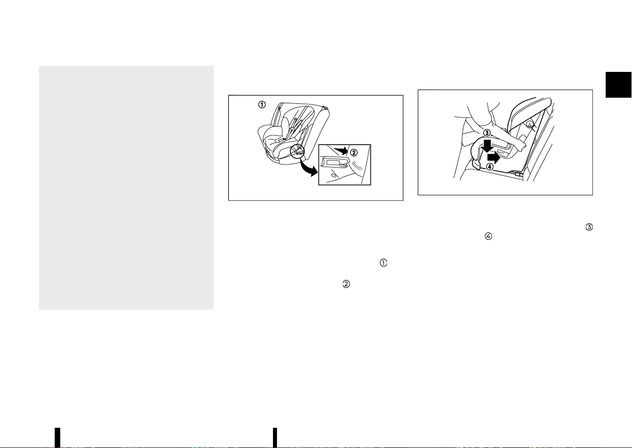
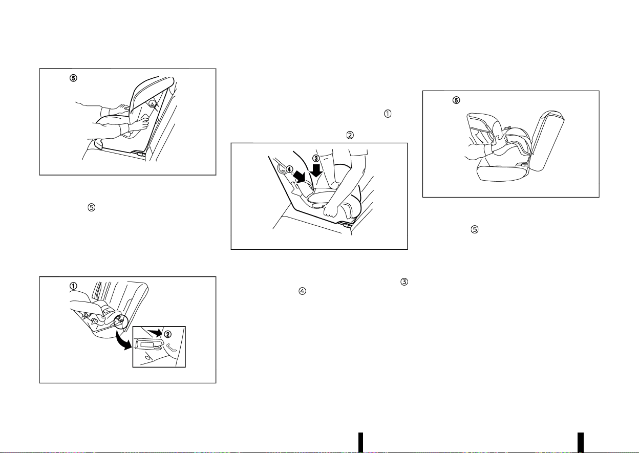
Front-facing:
MSSS0646A
Front-facing: Steps 1 and 2
Be sure to follow the manufacturer’s instructions
for the proper use of your child restraint. Follow
these steps to install a front-facing child restraint
on the second row outboard seats using ISOFIX:
1. Position the child restraint on the seat
.
2. Secure the child restraint anchor attachments
to the ISOFIX lower anchors
.
3. The back of the child restraint should be
secured against the vehicle seat back. If
necessary, remove the head restraint to obtain
the correct child restraint fit. (See “Head
restraints” (P.25).) If the head restraint is
removed, store it in a secure place. Be sure to
install the head restraint when the child
restraint is removed. If the seating position
does not have an adjustable head restraint
and it is interfering with the proper child
restraint fit, try another seating position or a
different child restraint.
MSSS0754A
Front-facing: Step 4
4. Shorten the rigid attachment to have the child
restraint firmly tightened; press downward
and rearward firmly in the centre of the
child restraint with your knee to compress the
vehicle seat cushion and seatback.
5. If the child restraint is equipped with a top
tether strap, route the top tether strap and
secure the tether strap to the tether anchor
point. (See “Child restraint anchorage (for
second row seats)” (P.40).)
6. If the child restraint is equipped with other
anti-rotation devices such as support legs, use
them instead of the top tether strap following
the child restraint manufacturer’s instructions.
Safety — seats, seat belts and supplemental restraint system 41
(46,1)
42 Safety — seats, seat belts and supplemental restraint system
MSSS0755A
Front-facing: Step 7
7. Test the child restraint before you place the
child in it
. Push the child restraint from side
to side and tug it forward to make sure that it
is held securely in place.
8. Check to make sure that the child restraint is
properly secured prior to each use. If the child
restraint is loose, repeat steps 3 through 7.
Rear-facing:
MSSS0649A
Rear-facing: Steps 1 and 2
Be sure to follow the manufacturer’s instructions
for the proper use of your child restraint. Follow
these steps to install a rear-facing child restraint
on the rear outboard seats using ISOFIX:
1. Position the child restraint on the seat
.
2. Secure the child restraint anchor attachments
to the ISOFIX lower anchors
.
MSSS0756A
Rear-facing: Step 3
3. Shorten the rigid attachment to have the child
restraint firmly tightened; press downward
and rearward firmly in the centre of the
child restraint with your hand to compress the
vehicle seat cushion and seatback.
4. If the child restraint is equipped with a top
tether strap, route the top tether strap and
secure the tether strap to the tether anchor
point. (See “Child restraint anchorage (for
second row seats)” (P.40).)
5. If the child restraint is equipped with other
anti-rotation devices such as support legs, use
them instead of the top tether strap following
the child restraint manufacturer’s instructions.
MSSS0757A
Rear-facing: Step 6
6. Test the child restraint before you place the
child in it
. Push the child restraint from side
to side and tug it forward to make sure that it
is held securely in place.
7. Check to make sure that the child restraint is
properly secured prior to each use. If the child
restraint is loose, repeat steps 3 through 6.
CHILD RESTRAINT INSTALLATION USING
THREE-POINT TYPE SEAT BELT
MEVT33A1-69C7CC4F-9441-4B39-9FB3-009D9128650E
Installation on rear seats
MEVT33A1-8ECFA200-03F0-4930-8350-8DD2E1757D6B
If you install a child restraint on the third row seat,
slide the second row seat to the frontmost
position (Three row model).
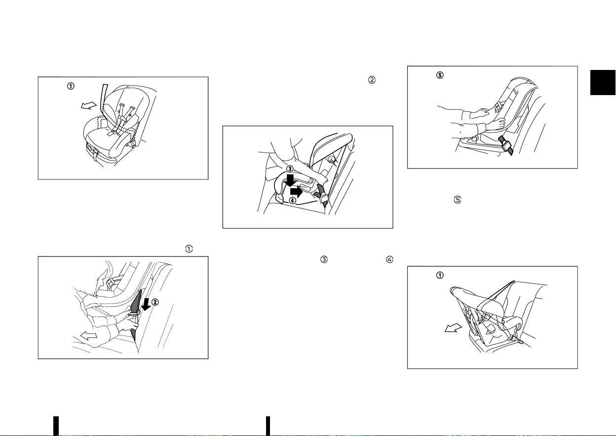
(47,1)
Front-facing:
MSSS0758A
Front-facing: Step 1
Be sure to follow the manufacturer’s instructions
for the proper use of your child restraint. Follow
these steps to install a front-facing child restraint
on the rear seats using three-point type seat belt
without automatic locking mode:
1. Position the child restraint on the seat
.
MSSS0493A
Front-facing: Step 2
2. Route the seat belt tongue through the child
restraint and insert it into the buckle
until
you hear and feel the latch engage.
3. To prevent slack in the seat belt webbing, it is
necessary to secure the seat belt in place with
locking devices attached to the child restraint.
MSSS0647A
Front-facing: Step 4
4. Remove any additional slack from the seat
belt; press downward
and rearward
firmly in the centre of the child restraint with
your knee to compress the vehicle seat
cushion and seatback while pulling up on the
seat belt. Adjustable seatbacks should be
positioned to ensure full contact between
child restraint and seatback.
MSSS0638A
Front-facing: Step 5
5. Test the child restraint before you place the
child in it
. Push the child restraint from side
to side and tug it forward to make sure that it
is held securely in place.
6. Check to make sure that the child restraint is
properly secured prior to each use. If the child
restraint is loose, repeat steps 3 through 5.
Rear-facing:
MSSS0759A
Rear-facing: Step 1
Safety — seats, seat belts and supplemental restraint system 43
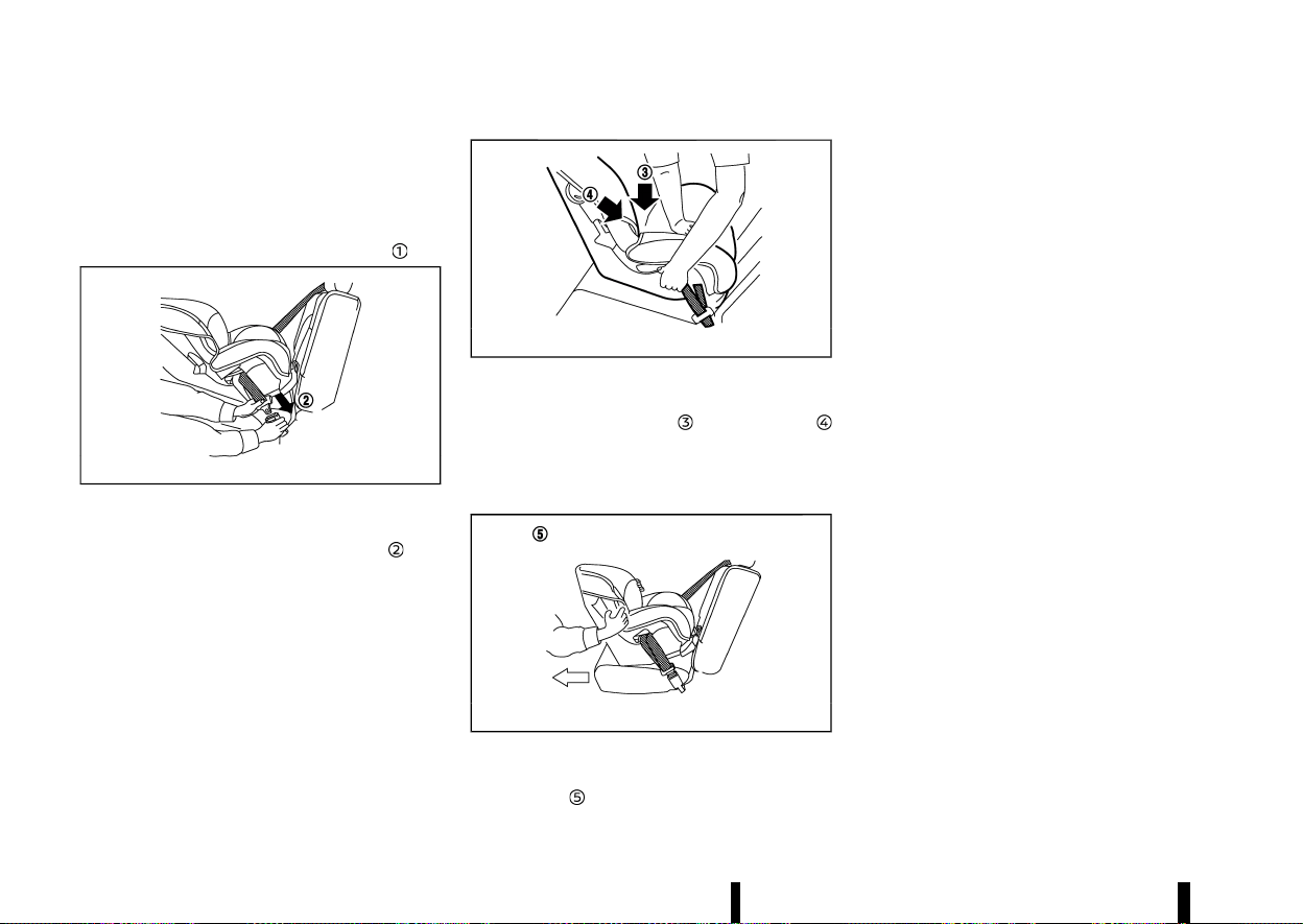
(48,1)
44 Safety — seats, seat belts and supplemental restraint system
Be sure to follow the manufacturer’s instructions
for the proper use of your child restraint. Follow
these steps to install a rear-facing child restraint
on the rear seats using three-point type seat belt
without automatic locking mode:
1. Position the child restraint on the seat
.
MSSS0654A
Rear-facing: Step 2
2. Route the seat belt tongue through the child
restraint and insert it into the buckle
until
you hear and feel the latch engage.
3. To prevent slack in the seat belt webbing, it is
necessary to secure the seat belt in place with
locking devices attached to the child restraint.
MSSS0639A
Rear-facing: Step 4
4. Remove any additional slack from the seat
belt; press downward
and rearward
firmly in the centre of the child restraint with
your hand to compress the vehicle seat
cushion and seatback while pulling up on the
seat belt.
MSSS0658A
Rear-facing: Step 5
5. Test the child restraint before you place the
child in it
. Push the child restraint from side
to side and tug it forward to make sure that it
is held securely in place.
6. Check to make sure that the child restraint is
properly secured prior to each use. If the child
restraint is loose, repeat steps 3 through 5.
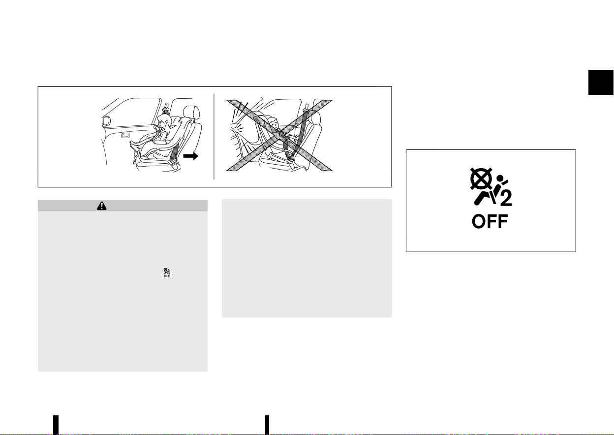
(49,1)
Installation on front passenger’s seat
MEVT33A1-8B368645-FDFF-41D0-8CF2-8CE77A67A49D
MSSS0300A
WARNING
* Never install a rear-facing child restraint
on the front passenger seat without en-
suring that the front passenger air bag is
deactivated. The vehicle is equipped with
an automatic front-passenger front air
bag deactivation system. The <PASSENGER
AIR BAG OFF> indicator light
, located
on the roof console, must be lit. In a frontal
collision, supplemental front-impact air
bags inflate with great force. An inflating
supplemental front-impact air bag could
seriously injure or kill your child.
* Never install a child restraint with a top
tether strap on the front seat.
* NISSAN recommends that a child restraint
be installed on the rear seat. However, if
you must install a child restraint on the
front passenger’s seat, move the passen-
ger’s seat to the rearmost position.
* Child restraints for infants must be used in
the rear-facing direction and therefore
must not be used on the front passenger’s
seat when the front passenger’s air bag is
available.
* Failure to use the seat belts will result in
the child restraint not being properly
secured. It could tip over or otherwise be
unsecured and cause injury to the child in a
sudden stop or collision.
Front-facing:
Be sure to follow the manufacturer’s instructions
for the proper use of your child restraint. Follow
these steps to install a front-facing child restraint
on the front passenger’s seat using a three-point
type seat belt.
If the child restraint is installed on the front
passenger seat, place the ignition switch in the
ON position. The front passenger air bag status
light <PASSENGER AIR BAG OFF>, located on the
roof console, should illuminate. If this light is not
illuminated, see “Supplemental Restraint System
(SRS)” (P.47). Move the child restraint to another
seating position. Have the system checked by a
NISSAN dealer or qualified workshop.
MSSS1099
Front passenger air bag status light <OFF>
Safety — seats, seat belts and supplemental restraint system 45
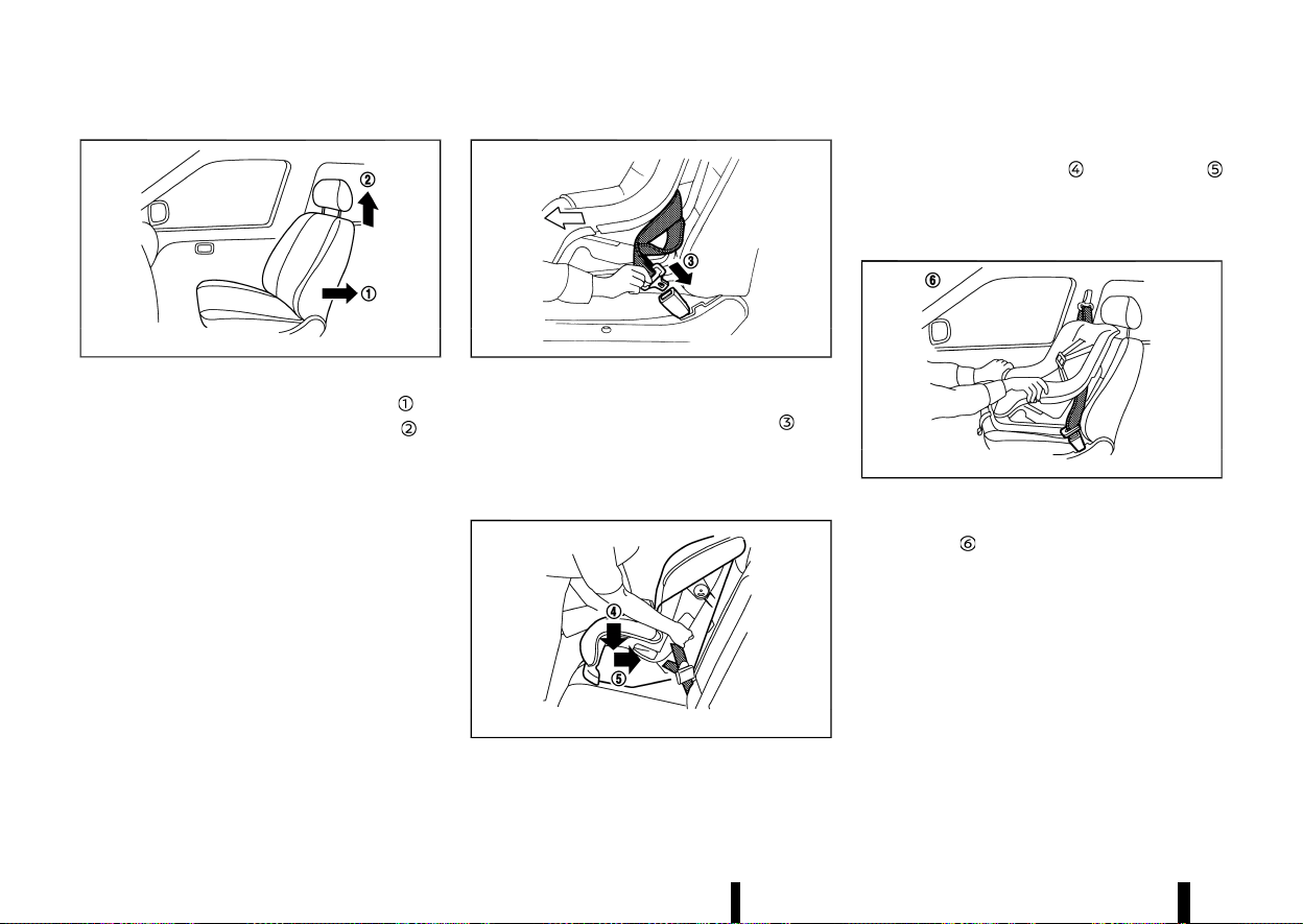
(50,1)
46 Safety — seats, seat belts and supplemental restraint system
MSSS0627
Front-facing: Steps 1 and 2
1. Move the seat to the rearmost position .
2. Adjust or remove the head restraint
to
obtain the correct child restraint fit.
3. Adjust the seat lifter to the uppermost posi-
tion.
4. Position the child restraint in the seat.
Always follow the child restraint system
manufacturer’s instructions for installation
and use.
MSSS0360C
Front-facing: Step 4
5. Route the seat belt tongue through the child
restraint and insert it into the buckle
until
you hear and feel the latch engage.
6. To prevent slack in the seat belt webbing, it is
necessary to secure the seat belt in place with
locking devices attached to the child restraint.
MSSS0647B
Front-facing: Step 6
7. Remove any additional slack from the seat
belt; press downward
and rearward
firmly in the centre of the child restraint with
your knee to compress the vehicle seat
cushion and seatback while pulling up on the
seat belt.
MSSS0302G
Front-facing: Step 7
8. Test the child restraint before you place the
child in it
. Push the child restraint from side
to side and tug it forward to make sure that it
is held securely in place.
9. Check to make sure that the child restraint is
properly secured prior to each use. If the child
restraint is loose, repeat steps 5 through 7.
If the child restraint is still loose, do not use
it. Please check the child restraint system
manufacturer’s instructions for installation
and use. Seek advice from a NISSAN dealer
or qualified workshop.
10. Place the ignition switch in the ON position.
Check the front passenger air bag status light
located on the roof console. The front pas-

(51,1)
senger air bag status light (OFF) should
illuminate.
MEVT33A1-8856DC89-886E-4202-AE5E-C7AEFD91CAD0
PRECAUTIONS ON SUPPLEMENTAL RE-
STRAINT SYSTEM (SRS)
MEVT33A1-60FC2972-4697-4A8A-931A-4A87EED5F877
This Supplemental Restraint System (SRS) section
contains important information concerning the
driver’s and passenger’s supplemental front-im-
pact air bags, supplemental side-impact air bags,
supplemental front central side-impact air bag,
supplemental curtain side-impact air bags and
pre-tensioner seat belts.
Supplemental front-impact air bag system
MEVT33A1-8CD31616-7BFB-438F-9A3A-A3ECCAC2AAA5
This system can help cushion the impact force to
the head and chest areas of the driver and/or front
passenger in certain frontal collisions. The supple-
mental front-impact air bag is designed to inflate
on the front where the vehicle is impacted.
Supplemental side-impact air bag system
MEVT33A1-A8A3BF71-EDC6-4077-AA0A-75D0189227C5
This system can help cushion the impact force to
the chest and pelvis areas of the driver and front
passenger in certain side-impact collisions. The
supplemental side-impact air bag is designed to
inflate on the side where the vehicle is impacted.
Supplemental front central side-impact air bag system
MEVT33A1-BFDDB454-0377-4CF4-BB27-09A252C6CCB9
This system can help cushion the impact force to
the head area of the driver and front passenger in
certain side impact collisions.
The front central side-impact air bag is designed to
inflate in the front central area where the vehicle is
impacted.
Supplemental curtain side-impact air bag system
MEVT33A1-88FCAD40-BCB6-4913-9A97-3FD9B5B86D64
This system can help cushion the impact force to
the head of the driver and passengers in front and
rear outboard seating positions in certain side-
impact collisions. The supplemental curtain side-
impact air bag is designed to inflate on the side
where the vehicle is impacted.
The SRS is designed to supplement the accident
protection provided by the seat belts and is not
designed to substitute for them. The SRS can help
save lives and reduce serious injuries. However,
inflating air bags may cause abrasions or other
injuries. Air bags do not provide protection to the
lower body. Seat belts should always be correctly
worn and the occupants should always be seated
a suitable distance away from the steering wheel,
instrument panel and door finishers. (See “Seat
belts” (P.28).) The air bags inflate quickly in order to
help protect the occupants. The force of the air
bags inflating can increase the risk of injury if the
occupants are too close to, or are against, the air
bag modules during inflation.
The front and side-impact air bags will deflate
quickly after deployment. The front central side-
impact air bag and curtain side-impact air bags
will remain inflated for a short period of time.
The SRS operates only when the ignition switch
is in the ON position.
When the ignition switch is in the ON position,
the SRS air bag warning light illuminates for
about 7 seconds and then turns off. This
indicates that the SRS is operational. (See “SRS
air bag warning light” (P.51).)
Safety — seats, seat belts and supplemental restraint system 47
SUPPLEMENTAL RESTRAINT SYSTEM (SRS)
SUPPLEMENTAL RESTRAINT SYSTEM (SRS)
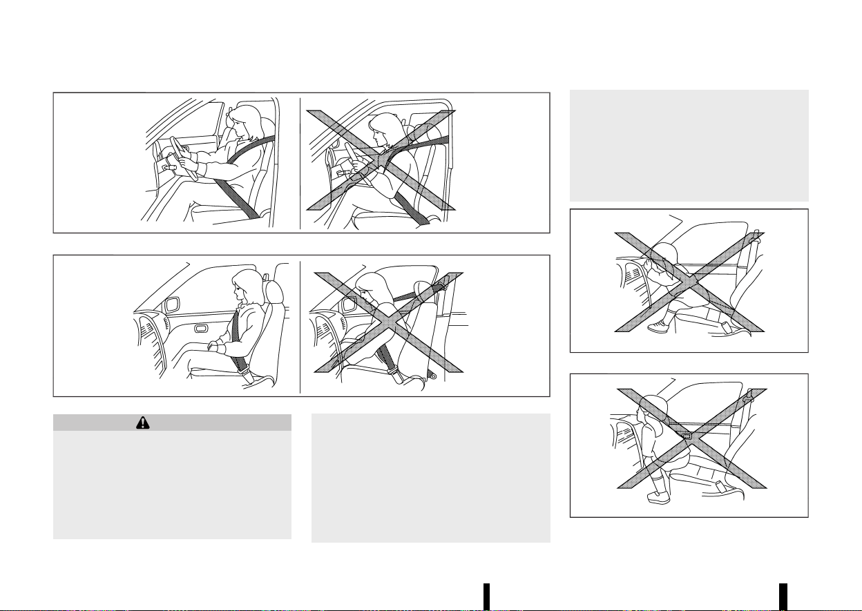
(52,1)
48 Safety — seats, seat belts and supplemental restraint system
MSSS0131A
MSSS0132A
WARNING
* The supplemental front air bags ordinarily
will not inflate in the event of a side impact,
rear impact, rollover, or lower severity
frontal collision. Always wear your seat
belts to help reduce the risk or severity of
injury in various kinds of accidents.
* The seat belts and the supplemental front-
impact air bags are most effective when
you are sitting well back and upright in the
seat. The front-impact air bags inflate with
great force. If you and your passengers are
unrestrained, leaning forward, sitting side-
ways, or out of position in any way, you
and your passengers are at greater risk of
injury or death in an accident. You and
your passengers may also receive serious
or fatal injuries from the supplemental
front-impact air bag if you are up against
it when it inflates. Always sit back against
the seatback and as far away as practical
from the steering wheel or instrument
panel. Always use the seat belts.
* Keep hands on the outside of the steering
wheel. Placing them inside the steering
wheel rim could increase the risk of injury
if the supplemental front air bag inflates.
MSSS0006
MSSS0007
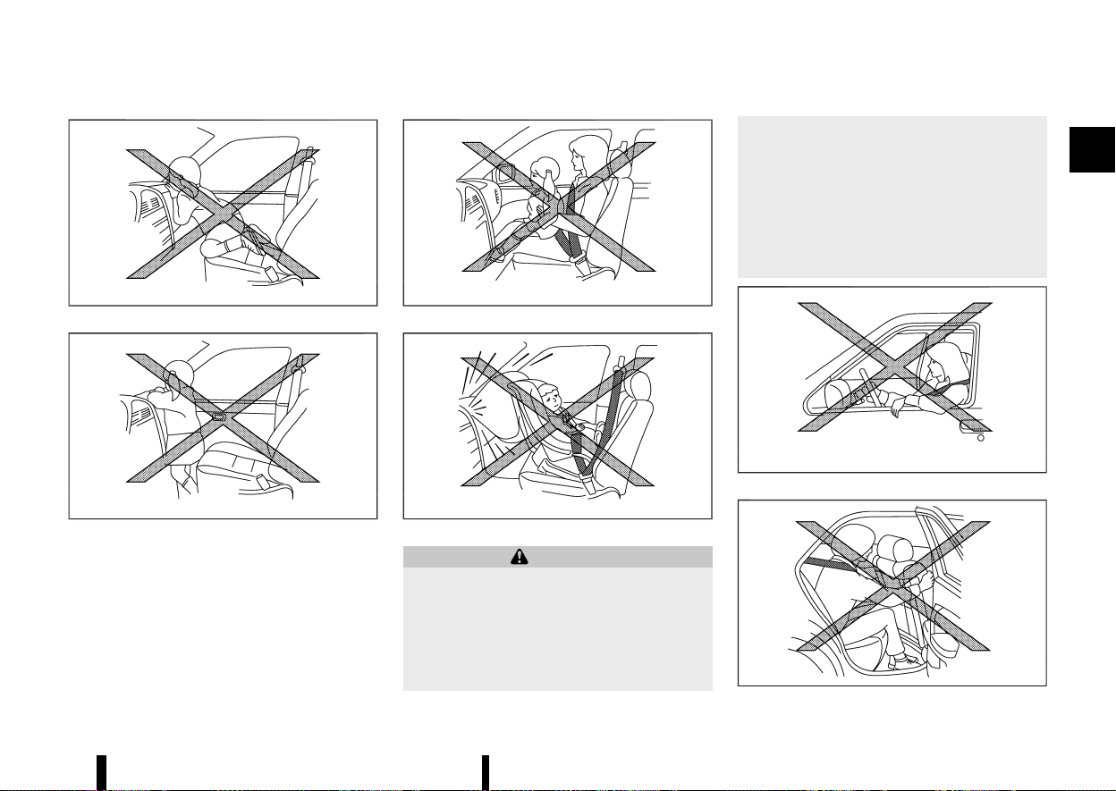
(53,1)
MSSS0008
MSSS0009
MSSS0099
MSSS0100
WARNING
* Never let children ride unrestrained or
extend their hands or face out of the
window. Do not attempt to hold them in
your lap or arms. Some examples of
dangerous riding positions are shown in
the illustrations.
* Children may be severely injured or killed
when the air bags inflate if they are not
properly restrained.
* Never install a rear-facing child restraint
system on the front passenger seat with-
out ensuring that the front passenger air
bag is deactivated. An inflating supple-
mental front-impact air bag could ser-
iously injure or kill your child. (See “Child
restraints” (P.33).)
MSSS0059A
MSSS0140
Safety — seats, seat belts and supplemental restraint system 49
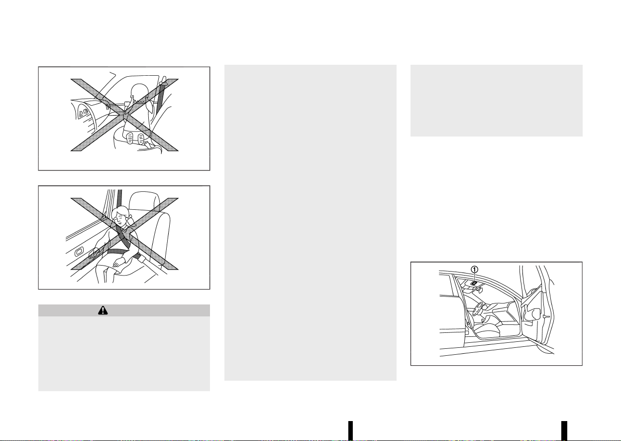
(54,1)
50 Safety — seats, seat belts and supplemental restraint system
MSSS0159
MSSS0162
WARNING
* The supplemental side-impact air bags,
supplemental front central side-impact
air bag and supplemental curtain side-
impact air bags ordinarily will not inflate
in the event of a front impact, rear impact,
rollover, or lower severity side collision.
Always wear the seat belts to help reduce
the risk or severity of injury in accidents.
* The seat belts and the supplemental front
central side-impact air bag, supplemental
side-impact air bags and supplemental
curtain side-impact air bags are most
effective when you are sitting well back
and upright in the seat. The supplemental
front central side-impact air bag, supple-
mental side-impact air bags and supple-
mental curtain side-impact air bags inflate
with great force. If you and your passen-
gers are unrestrained, leaning forward,
sitting sideways, or out of position in any
way, you and your passengers are at
greater risk of injury or death in an
accident.
* Do not allow anyone to place their hands,
legs or face near the supplemental front
central side-impact air bag, supplemental
side-impact air bags, supplemental curtain
side-impact air bags located on the centre
of the seatback of the driver’s seat, the
sides of the seatback of the front seats or
near the side roof rails. Do not allow
anyone sitting in the front seats or rear
outboard seats to extend their hands out
of the windows or lean against the doors.
Some examples of dangerous riding posi-
tions are shown in the illustrations.
* When sitting in the rear seats, do not hold
onto the seatback of the front seats. If the
supplemental front central side-impact air
bag, supplemental side-impact air bags
and supplemental curtain side-impact air
bags inflate, you may be seriously injured.
Be especially careful with children, who
should always be properly restrained.
* Do not use seat covers on the front seat-
backs. They may interfere with the supple-
mental front central side-impact air bag
and supplemental side-impact air bag
inflations.
Pre-tensioner seat belt system
MEVT33A1-32B7DC7A-6FA3-4EC7-AD61-D2C633EDA99E
The pre-tensioner seat belt system may activate
with the supplemental air bag system in certain
types of collisions.
Working with the seat belt retractors and front lap
outer anchors, it helps tighten the seat belt the
instant the vehicle becomes involved in certain
types of collisions, helping to restrain front and
second row outboard seat occupants. (See “Pre-
tensioner seat belt system” (P.58).)
Air bag warning labels
MEVT33A1-96A7D1AB-55EC-467D-865A-E6466B19753A
MJVR0033X
Warning labels about the supplemental air bag
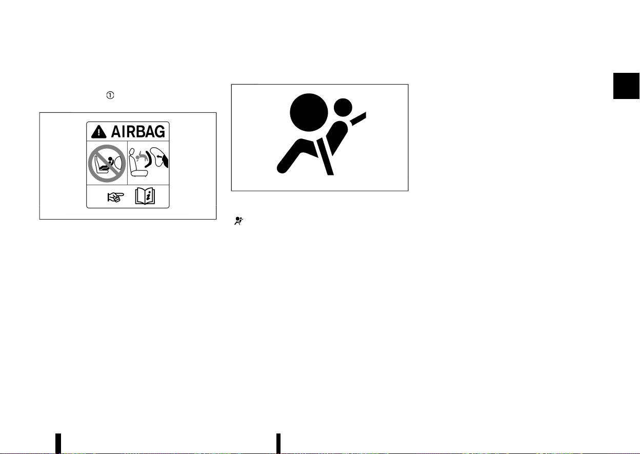
(55,1)
system are placed in the vehicle as shown in the
illustration.
The warning label
is located on the surface of
the front passenger’s sun visor.
MWAB0183X
The label warns:
“NEVER use a rearward facing child restraint on a
seat protected by an ACTIVE AIR BAG in front of it,
DEATH or SERIOUS INJURY to the CHILD can occur.”
In vehicles equipped with a front-impact passen-
ger air bag system, use a rear-facing child restraint
system only on the rear seats.
When installing a child restraint system in your
vehicle, always follow the child restraint system
manufacturer’s instructions for installation. For
additional information, see “Child restraints” (P.33).
SRS air bag warning light
MEVT33A1-95B40408-0D83-4746-A726-7433FD0FEE9A
MSPA1097
The supplemental air bag warning light, displaying
in the meter monitors the circuits for the air
bag systems, pre-tensioner seat belt system and
all related wiring.
When the ignition switch is in the ON position, the
SRS air bag warning light illuminates for about 7
seconds and then turns off. This indicates that the
SRS air bag systems are operational.
If any of the following conditions occur, the air bag
and/or pre-tensioner seat belt systems need
servicing:
* The SRS air bag warning light remains on after
approximately 7 seconds.
* The SRS air bag warning light does not
illuminate at all.
Under these conditions, the air bag, pre-tensioner
seat belt and/or occupant classification sensor
systems may not operate properly. They must be
checked and repaired. Contact a NISSAN dealer or
qualified workshop immediately.
Safety — seats, seat belts and supplemental restraint system 51
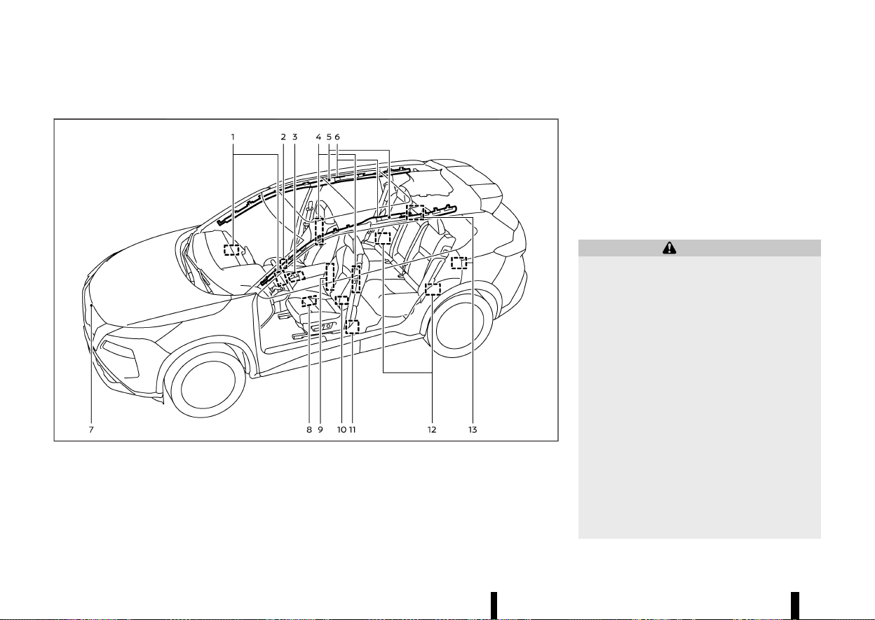
(56,1)
52 Safety — seats, seat belts and supplemental restraint system
SUPPLEMENTAL AIR BAG SYSTEMS
MEVT33A1-768CC898-B90C-429B-A8AD-5266C08A2F3F
MWAB0327X
Example (Two row model shown)
1. Supplemental front-impact air bag modules
2. Occupant classification sensor (front pas-
senger’s seat)
3. Air bag Control Unit (ACU)
4. Supplemental side-impact air bag modules
5. Supplemental curtain side-impact air bag
inflators
6. Supplemental curtain side-impact air bag
modules
7. Crash zone sensor
8. Front door pressure sensors (left-side
shown; right-side similar)
9. Supplemental front central side-impact air
bag modules (driver’s seat)
10. Lap outer pre-tensioners (front)
11. Seat belt pre-tensioner retractors (front)
12. Satellite sensors (rear)
13. Seat belt pre-tensioner retractors (second
row outboard seats)
WARNING
* Do not place any objects on the steering
wheel pad, on the instrument panel, and
near the front door finishers and the front
seats. Do not place any objects between
any occupants and the steering wheel pad,
on the instrument panel, and near the
front door finishers and the front seats.
Such objects may become dangerous pro-
jectiles and cause injury if a supplemental
air bag inflates.
* Immediately after inflation, several supple-
mental air bag system components will be
hot. Do not touch them: you may severely
burn yourself.
* No unauthorised changes should be made
to any components or wiring of the sup-
plemental air bag systems. This is to
prevent accidental inflation of the supple-
mental air bags or damage to the supple-
mental air bag systems.
* Do not make unauthorised changes to
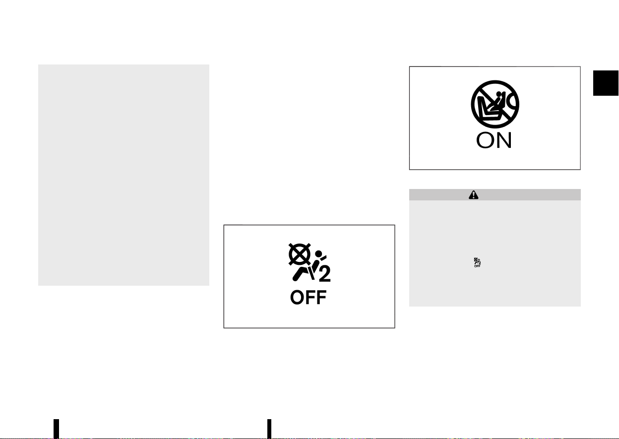
(57,1)
your vehicle’s electrical system, suspen-
sion system, front end structure and side
panels. This could affect proper operation
of the supplemental air bag systems.
* Tampering with the supplemental air bag
systems may result in serious personal
injury. Tampering includes changes to the
steering wheel and the instrument panel
by placing materials over the steering
wheel pad and above, around or on the
instrument panel or by installing addi-
tional trim materials around the supple-
mental air bag systems.
* Work on and around the supplemental air
bag systems should be done by a NISSAN
dealer or qualified workshop. The SRS
wiring should not be modified or discon-
nected. Unauthorised electrical test equip-
ment and probing devices should not be
used on the supplemental air bag systems.
* The SRS wiring harness connectors are
yellow and/or orange for easy identifica-
tion.
When the air bags inflate, a fairly loud noise may be
heard, followed by the release of smoke. This
smoke is not harmful and does not indicate a fire.
Care should be taken not to inhale it, as it may
cause irritation and choking. Those with a history
of a breathing condition should get fresh air
promptly.
Supplemental front-impact air bag system
MEVT33A1-91C5CE86-CC23-4AF9-9ACA-97772C7138AD
The driver’s supplemental front-impact air bag is
located at the centre of the steering wheel. The
passenger’s supplemental front-impact air bag is
located at the instrument panel above the glove
box.
The supplemental front-impact air bag system is
designed to inflate in higher severity frontal
collisions, although it may inflate if the forces in
another type of collision are similar to those of a
higher severity frontal impact. It may not inflate in
certain frontal collisions. Vehicle damage (or lack
of it) is not always an indication of proper
supplemental front-impact air bag system opera-
tion.
Front passenger air bag status light:
MSSS1099
OFF light
MJVR0264X
ON light
WARNING
Never install a rear-facing child restraint sys-
tem on the front passenger seat without
ensuring that the front passenger air bag is
deactivated. The vehicle is equipped with an
automatic front-passenger front air bag deac-
tivation system. The <PASSENGER AIR BAG
OFF> indicator
must be lit. In a frontal
collision, supplemental front impact air bags
inflate with great force. An inflating supple-
mental front-impact air bag could seriously
injure or kill your child.
The front passenger seat is equipped with occu-
pant classification sensor that turns the front
passenger air bag on or off depending on the type
of occupant or object detected on the front
passenger seat. The status of the front passenger
air bag (ON or OFF) is indicated by the front
passenger air bag status lights <PASSENGER AIR
Safety — seats, seat belts and supplemental restraint system 53
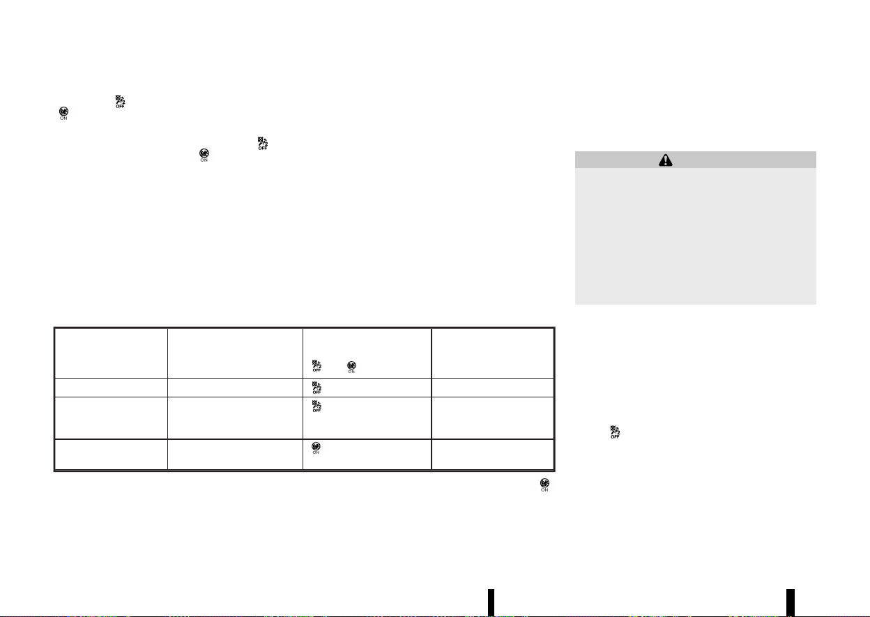
(58,1)
54 Safety — seats, seat belts and supplemental restraint system
BAG OFF> and <PASSENGER AIR BAG ON>
which are located on the roof console.
After the ignition switch is placed in the "ON"
position, the <PASSENGER AIR BAG OFF>
and
<PASSENGER AIR BAG ON>
indicator lights
must light up simultaneously for approximately 7
seconds.
The indicator lights display the status of the front
passenger front air bag:
* <PASSENGER AIR BAG ON> lights up: the front
passenger front air bag is enabled. If, in the
event of an accident, all deployment criteria
are met, the front passenger front air bag is
deployed.
* <PASSENGER AIR BAG OFF> lights up: the front
passenger front air bag is disabled. It will then
not be deployed in the event of an accident.
CONDITION DESCRIPTION PASSENGER AIR BAG INDI-
CATOR LIGHT
OR
FRONT PASSENGER AIR
BAG STATUS
Empty Empty front passenger seat
illuminated INHIBITED
Nissan recommended
child restraint with
child
Bag or Child Restraint in
front passenger seat*
illuminated INHIBITED
Adult Adult in the front passenger
seat
illuminated ACTIVATED
* If an approved child restraint system is not being used, the passenger air bag may be active (
illuminated).
In addition to the above, certain objects placed on
the front passenger seat may also cause the light
to operate as described above.
For additional information related to the normal
operation and troubleshooting of this occupant
classification sensor system, please refer to “Trou-
bleshooting” later in this section.
Automatic front-passenger air bag deactivation
system:
WARNING
The front passenger air bag is designed to
automatically turn OFF under some conditions.
Read this section carefully to learn how it
operates. Proper use of the seat, seat belt
and child restraints is necessary for most
effective protection. Failure to follow all in-
structions in this manual concerning the use of
seats, seat belts and child restraints can
increase the risk or severity of injury in an
accident.
In order to recognize a child restraint system on
the front-passenger seat, the automatic front-
passenger front air bag deactivation system
categorises the person in the front passenger seat
using an occupant classification sensor. Depend-
ing on that result, the front-passenger front air
bag is either enabled or disabled. If a NISSAN
recommended child restraint system is fitted to
the front passenger seat, the <PASSENGER AIR BAG
OFF>
indicator light must light up after the
system self-test and remain lit. The front passen-
ger front air bag is disabled.
The occupant classification sensor in this vehicle is
designed to detect the type of occupant or objects
on the seat. For example, if an approved child
restraint on the seat, it can be detected together
with the child and cause the air bag to turn OFF.
Front passenger seat adult occupants who are

(59,1)
properly seated and using the seat belt as outlined
in this manual should automatically cause the
passenger air bag to be turned ON. However, if the
occupant is not sitting correctly on the seat
cushion (for example, by not sitting upright, by
sitting on an edge of the seat, or by otherwise
being out of position), this could cause the sensor
to turn the air bag OFF. Always be sure to be
seated and wearing the seat belt properly for the
most effective protection by the seat belt and
supplemental air bag.
NISSAN recommends that pre-teens and children
be properly restrained in a rear seat. NISSAN also
recommends that appropriate child restraints and
booster seats be properly installed in a rear seat. If
this is not possible, the occupant classification
sensor is designed to operate as described above
to turn the front passenger air bag OFF for NISSAN
recommended child restraints. Failing to properly
secure child restraints may allow the restraint to
tip or move in an accident or sudden stop. This can
also result in the passenger air bag inflating in a
crash instead of being OFF. (See “Child restraints”
later in this section for proper use and installation.)
If the front passenger seat is not occupied, the
passenger air bag are designed not to inflate in a
crash. However, heavy objects placed on the seat
could result in air bag inflation, because of the way
the object is detected by the occupant classifica-
tion sensor. Other conditions could also result in
air bag inflation, such as if a child is standing on
the seat, or if two children are on the seat, if the
seat is wet, or if an electrical device is on the seat,
contrary to the instructions in this manual. Always
be sure that you and all vehicle occupants are
seated and restrained properly.
Using the front passenger air bag status light, you
can monitor when the front passenger air bag is
automatically turned OFF.
If an adult occupant is in the seat but the
<PASSENGER AIR BAG OFF>
indicator light is
illuminated (indicating that the front passenger air
bag is OFF), it could be that the person is not
sitting on the seat properly. If a seat cover or
additional cushion is used, this may also prevent
the occupant classification sensor from detecting
an adult correctly.
If a child restraint must be used in the front seat,
the <PASSENGER AIR BAG OFF>
indicator light
may or may not be illuminated, depending on the
size of the child and the type of child restraint
being used. If the <PASSENGER AIR BAG OFF>
light is not illuminated (indicating that the air bag
might inflate in a crash), it could be that the child
restraint or seat belt is not being used properly.
Make sure that the child restraint is installed
properly, the seat belt is used properly and the
occupant is positioned properly. If the <PASSEN-
GER AIR BAG OFF>
light is not illuminated,
reposition the occupant or child restraint in a rear
seat.
If the <PASSENGER AIR BAG OFF>
light will not
illuminate even though you believe that the child
restraint, the seat belts and the occupant are
properly positioned, it is recommended that you
take your vehicle to a NISSAN dealer or qualified
workshop. A NISSAN dealer or qualified workshop
can check the system status by using a special
tool. However, until you have confirmed with your
dealer that your air bag is working properly,
reposition the occupant or child restraint in a rear
seat.
The air bag system and front passenger air bag
status lights will take a few seconds to register a
change in the passenger seat status. This is
normal system operation and does not indicate a
malfunction.
If a malfunction occurs in the front passenger air
bag system, the supplemental air bag warning
light
, located in the meters and gauges area,
will illuminate (blinking or steadily lit). Also, if the
seat is wet and the system cannot work correctly,
the system will deactivate the passenger air bag
temporarily and illuminate the supplemental air
bag warning light until seat is dry. Have the system
checked. It is recommended you visit a NISSAN
dealer or qualified workshop for this service.
Normal operation:
In order for the occupant classification sensor
system to classify the front passenger, please
follow the precautions and steps outlined below:
Precautions:
* Make sure that a child restraint or other object
is not pressing against the rear of the seat-
back.
* Make sure that a rear passenger is not
pushing or pulling on the back of the front
passenger seat.
* Make sure that the front passenger seat or
seatback is not forced back against an object
on the seat or floor behind it.
Safety — seats, seat belts and supplemental restraint system 55

(60,1)
56 Safety — seats, seat belts and supplemental restraint system
* Make sure that there is no object placed under
the front passenger seat.
* Make sure that the front passenger seat head
restraint does not contact the roof when
adjusting the front passenger seat.
* Make sure the seat is dry.
* Make sure no electrical devices are placed on
the seat.
* Make sure additional non-original seat covers
or cushions are not used on the front passen-
ger seat.
* Make sure the occupant of the seat is not
wearing heavily padded clothing items.
Steps:
1. Adjust the seat as outlined. (See “Seats” earlier
in this section.) Sit upright, leaning against the
seatback, and centered on the seat cushion
with your feet comfortably extended to the
floor.
2. Make sure there are no objects on your lap.
3. Fasten the seat belt as outlined. (See “Seat
belts” earlier in this section.) Front passenger
seat belt buckle status is monitored by the
occupant classification system, and is used as
an input to determine occupancy status. So, it
is highly recommended that the front passen-
ger fastens their seat belt.
4. Remain in this position for several seconds
allowing the system to classify the front
passenger before the vehicle is put into
motion.
5. Ensure proper classification by checking the
front passenger air bag status light.
NOTE:
This vehicle’s occupant classification sensor
system generally keeps the classification locked
during driving, so it is important that you
confirm that the front passenger is properly
classified prior to driving. However, the occupant
classification sensor system may recalculate the
classification of the occupant under some con-
ditions (both while driving and when stopped),
so the front passenger seat occupant should
continue to remain seated as outlined above.
WARNING
If the <PASSENGER AIR BAG OFF> indicator
light is lit, the front-passenger front air bag is
disabled. It will not be deployed in the event of
an accident and cannot perform its intended
protective function. A person in the front
passenger seat could then, for example, come
into contact with the vehicle’s interior, espe-
cially if the person is sitting too close to the
dashboard. This poses an increased risk of
injury or even fatal injury.
When the front-passenger seat is occupied,
always make sure that:
* The classification of the person in the front
passenger seat is correct and that the
front passenger front air bag is enabled
or disabled in accordance with the person
in the front passenger seat.
* The front-passenger seat has been moved
back as far back as possible.
* The person is seated correctly.
If you secure a child on the front passenger
seat in a rearward-facing child restraint sys-
tem and the <PASSENGER AIR BAG ON>
indicator lights up, the passenger’s air bag
could be deployed in the event of an accident.
The child could be struck by the air bag. There
is an increased risk of injury, possibly even
fatal. In this case, always ensure that the
passenger’s air bag is disabled. The <PASSEN-
GER AIR BAG OFF>
indicator must light up.
Troubleshooting:
If you think the front passenger air bag status light
is incorrect:
1. If the <PASSENGER AIR BAG OFF>
light is
lit with an adult occupying the front passen-
ger seat:
This may be due to the following conditions that
may be interfering with the occupant classification
sensor:
* Occupant is not sitting upright, leaning
against the seatback, and centered on the
seat cushion with his/her feet comfortably
extended to the floor.
* A child restraint or other object pressing
against the rear of the seatback.
* A rear passenger pushing or pulling on the
back of the front passenger seat.
* Forcing the front seat or seatback against an
object on the seat or floor behind it.
* An object placed under the front passenger
seat.
* An object placed between the seat cushion
and centre console or between the seat
cushion and the door.
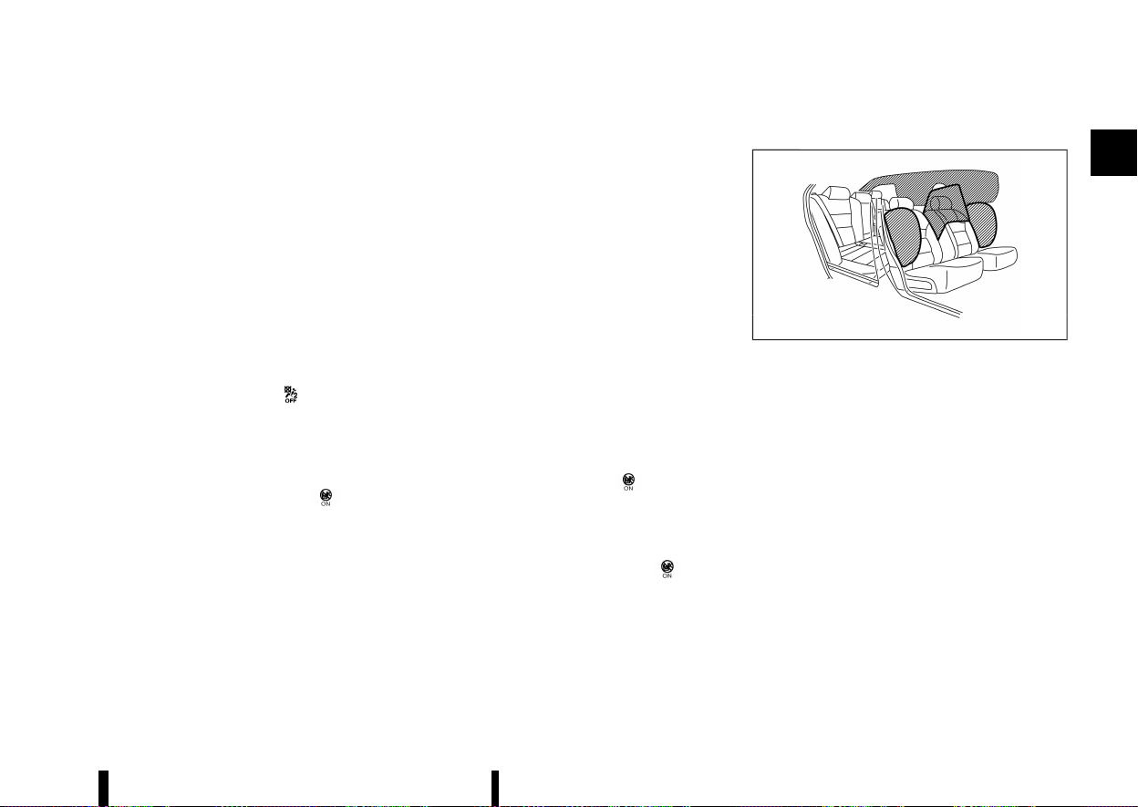
(61,1)
* The seat is wet or damp.
* An electrical device like a smartphone or tablet
PC is placed on the seat.
* Non-original seat covers or cushions are used
on the front passenger seat
* The occupant of the seat is wearing heavily
padded clothing items.
If the vehicle is moving, please come to a stop
when it is safe to do so. Check and correct any of
the above conditions. Restart the vehicle.
NOTE:
A system check will be performed during which
the front passenger air bag status lights will
remain lit for about 7 seconds initially.
If the <PASSENGER AIR BAG OFF>
light is still lit
after this, the person should be advised not to ride
in the front passenger seat and the vehicle should
be checked as soon as possible. It is recommended
you visit a NISSAN dealer or qualified workshop for
this service.
2. If the <PASSENGER AIR BAG ON>
light is
lit with a child restraint occupying the front
passenger seat.
This may be due to the following conditions that
may be interfering with the occupant classification
sensor:
* The child restraint is not properly installed, as
outlined. (See “Child restraints” (P.33).)
* A child restraint or other object pressing
against the rear of the seatback.
* A rear passenger pushing or pulling on the
back of the front passenger seat.
* Forcing the front seat or seatback against an
object on the seat or floor behind it.
* An object placed under the front passenger
seat.
* An object placed between the seat cushion
and centre console or between the seat
cushion and the door.
* The seat is wet or damp.
* An electrical device like a smartphone or tablet
PC is placed on the seat.
* The front passenger seat head restraint con-
tacting the roof.
If the vehicle is moving, please come to a stop
when it is safe to do so. Check and correct any of
the above conditions. Restart the vehicle.
NOTE:
A system check will be performed during which
the front passenger air bag status light will
remain lit for about 7 seconds initially.
If the <PASSENGER AIR BAG ON>
light is still lit
after this, the child restraint should be reposi-
tioned in the rear seat and it is recommended that
the vehicle should be checked by a NISSAN dealer
or qualified workshop as soon as possible.
3. If the <PASSENGER AIR BAG ON>
light is
lit with no front passenger and no objects on
the front passenger seat, the vehicle should
be checked as soon as possible. It is recom-
mended you visit a NISSAN dealer or qualified
workshop for this service.
Supplemental side-impact air bag system
MEVT33A1-292062D9-9E1E-4D27-B5D8-016B8CE59B05
MWAB0324X
The supplemental side-impact air bag is located at
the outside of the front seats’ seatbacks.
The supplemental side-impact air bag system is
designed to inflate in higher severity side collisions,
although it may inflate if the forces in another type
of collision are similar to those of a higher severity
side impact. It may not inflate in certain side
collisions. Vehicle damage (or lack of it) is not
always an indication of proper supplemental side-
impact air bag system operation.
Supplemental front central side-impact air bag system
MEVT33A1-C797EC14-D014-403E-A1B3-9B2E821F4D60
The supplemental front central side-impact air bag
is located at the inside of the driver’s seats’
seatback.
The supplemental front central side-impact air bag
system is designed to inflate in higher severity side
collisions, although it may inflate if the forces in
another type of collision are similar to those of a
higher severity side impact. It may not inflate in
Safety — seats, seat belts and supplemental restraint system 57

(62,1)
58 Safety — seats, seat belts and supplemental restraint system
certain side collisions. Vehicle damage (or lack of it)
is not always an indication of proper supplemental
side-impact air bag system operation.
Supplemental curtain side-impact air bag system
MEVT33A1-AA6A74A0-30F5-45CD-8A71-20A7032C7A29
The supplemental curtain side-impact air bag is
located at the roof rails.
The supplemental curtain side-impact air bag
system is designed to inflate in higher severity
side collisions, although it may inflate if the forces
in another type of collision are similar to those of a
higher severity side impact. It may not inflate in
certain side collisions. Vehicle damage (or lack of it)
is not always an indication of proper supplemental
curtain side-impact air bag system operation.
PRE-TENSIONER SEAT BELT SYSTEM
MEVT33A1-80C3FC50-BE55-4013-AADF-FBBF8BAD0906
WARNING
* The pre-tensioner seat belt cannot be
reused after activation. It must be replaced
together with the retractor and buckle as a
unit.
* If the vehicle becomes involved in a colli-
sion but the pre-tensioner is not activated,
be sure to have the pre-tensioner system
checked and, if necessary, replaced by a
NISSAN dealer or qualified workshop.
* No unauthorised changes should be made
to any components or wiring of the pre-
tensioner seat belt system. This is to
prevent accidental activation of the pre-
tensioner seat belt or damage to the pre-
tensioner seat belt system.
* Work around or on the pre-tensioner seat
belt system should be done by a NISSAN
dealer or qualified workshop. The SRS
wiring should not be modified or discon-
nected. Unauthorised electrical test equip-
ment and probing devices should not be
used on the pre-tensioner seat belt sys-
tem.
* If you need to dispose of the pre-tensioner
seat belt system, or scrap the vehicle,
contact a NISSAN dealer or qualified work-
shop. Correct pre-tensioner disposal pro-
cedures are set forth in the appropriate
NISSAN Service Manual. Incorrect disposal
procedures could cause personal injury.
The pre-tensioner seat belt system may activate
with the supplemental air bag system in certain
types of collisions.
Working with the seat belt retractor, it helps
tighten the seat belt when the vehicle becomes
involved in certain types of collisions, helping to
restrain the occupants.
The pre-tensioner is encased with the front and
second row outboard seat belt’s retractor and
anchor. These seat belts are used the same as
conventional seat belts.
When the pre-tensioner seat belt activates, a fairly
loud noise may be heard, followed by the release of
smoke. This smoke is not harmful and does not
indicate a fire. Care should be taken not to inhale it,
as it may cause irritation and choking. Those with
a history of a breathing condition should get fresh
air promptly.
REPAIR AND REPLACEMENT PROCE-
DURE
MEVT33A1-E2B60B7B-1FAF-4169-A358-663FE254DA22
WARNING
* Once the air bags have been inflated, the
air bag modules will not function and must
be replaced. The air bag modules must be
replaced by a NISSAN dealer or qualified
workshop. The inflated air bag modules
cannot be repaired.
* The air bag systems should be inspected
by a NISSAN dealer or qualified workshop if
there is any damage to the front end or
side portion of the vehicle.
* If you need to dispose of the SRS or scrap
the vehicle, contact a NISSAN dealer or
qualified workshop. Correct disposal pro-
cedures are set forth in the appropriate
NISSAN Service Manual. Incorrect disposal
procedures could cause personal injury.
* If there is an impact to your vehicle from
any direction, your occupant classification
sensor should be checked to verify it is still
functioning correctly. It is recommended
that you visit a NISSAN dealer or qualified
workshop for this service. The occupant
classification sensor should be checked
even if no air bags deploy as a result of
the impact. Failure to verify proper occu-
pant classification sensor function may
result in an improper air bag deployment
resulting in injury or death.
The air bags and pre-tensioner seat belts are

(63,1)
designed to activate on a one-time-only basis. As a
reminder, unless the SRS air bag warning light is
damaged, the SRS air bag warning light remains
illuminated after inflation has occurred. The repair
and replacement of the SRS should be done only
by a NISSAN dealer or qualified workshop.
When maintenance work is required on the vehicle,
information about the air bags, pre-tensioner seat
belts and related parts should be pointed out to
the person performing the maintenance. The
ignition switch should always be in the “OFF”
position when working under the bonnet or inside
the vehicle.
Safety — seats, seat belts and supplemental restraint system 59

(64,1)
60 Safety — seats, seat belts and supplemental restraint system
MEMO

(65,1)
2 Instruments and controls
Cockpit .................................................................................................................... 63
Left-Hand Drive (LHD) model ...................................................... 63
Right-Hand Drive (RHD) model .................................................. 64
Instrument panel ............................................................................................ 65
Left-Hand Drive (LHD) model ...................................................... 65
Right-Hand Drive (RHD) model .................................................. 66
Meters and gauges ....................................................................................... 67
Models with analog meter and colour display ............. 67
Models with full-screen display ................................................ 68
Speedometer and odometer ...................................................... 69
Tachometer .............................................................................................. 70
Engine coolant temperature gauge ..................................... 70
Fuel gauge ................................................................................................. 71
Instrument brightness control .................................................. 71
Continuously Variable Transmission (CVT)
position indicator ................................................................................. 72
ECO Drive Report .................................................................................. 72
Variable Compression Turbo ...................................................... 72
Warning lights, indicator lights and
audible reminders .......................................................................................... 74
Checking lights ...................................................................................... 75
Warning lights ......................................................................................... 75
Indicator lights ....................................................................................... 79
Audible reminders ................................................................................ 81
Vehicle information display .................................................................... 81
Changing the meter screen view (models with
full-screen display) ................................................................................ 82
How to use the vehicle information display .................... 82
Shortcut Menu .......................................................................................... 82
Startup display ......................................................................................... 82
[Settings] ....................................................................................................... 83
Vehicle information display warnings
and indicators ........................................................................................... 91
Trip computer ........................................................................................ 101
Clock and outside air temperature ...................................... 105
[Head Up Display (HUD)] (where fitted) ........................................ 105
How to use the HUD ......................................................................... 106
Driving Aids/Navigation/Traffic
Sign/Audio/Telephone linking .................................................. 107
Headlight and turn signal switch ..................................................... 108
Headlight switch .................................................................................. 108
Headlight cleaner (where fitted) ............................................. 112
Headlight aiming control .............................................................. 112
Turn signal switch .............................................................................. 115
Fog light switch .............................................................................................. 115
Front fog lights (where fitted) ................................................... 115
Rear fog light .......................................................................................... 116
Wiper and washer switch ....................................................................... 116
Windscreen wiper and washer operation ....................... 116
Rain-sensing auto wiper system ............................................ 117
Rear window wiper and washer operation ................... 118

(66,1)
Heated windscreen (where fitted) ................................................. 119
Defogger switch ........................................................................................... 119
Horn ........................................................................................................................ 120
Heated steering wheel switch (where fitted) ........................ 120
Rear Door Alert (where fitted) ........................................................... 121
Power outlets ................................................................................................. 122
USB (Universal Serial Bus) charging connector
(where fitted) ........................................................................................ 122
Wireless charger (where fitted) .............................................. 123
Emergency services call eCall/SOS system
(where fitted) ................................................................................................... 124
Automatic eCall .................................................................................. 124
Manual eCall (SOS button) ......................................................... 125
System status indicator ............................................................... 126
Modalities for exercising data subject’s rights .......... 126
Storage ................................................................................................................ 127
Cup holders ........................................................................................... 127
Soft bottle holders ........................................................................... 127
Glove box ................................................................................................. 128
Console box ........................................................................................... 128
Lower console tray .......................................................................... 128
Sunglasses holder ............................................................................ 128
Card holder ............................................................................................ 129
Coat hooks
....
......................................................................................... 129
Tonneau cover
....
................................................................................ 129
Luggage hooks
....
............................................................................... 130
Adjustable luggage floor (where fitted)
....
...................... 130
Luggage under space
....
............................................................... 132
Roof rack (where fitted)
....
..................................................................... 132
Windows
....
......................................................................................................... 133
Power windows
....
.............................................................................. 133
Sunroof (where fitted)
....
........................................................................... 135
Automatic sunroof and sunshade
....
.................................... 135
Sun visors
....
........................................................................................................ 137
Rear sunshade (where fitted)
....
.......................................................... 137
Interior lights
....
............................................................................................... 138
Interior light switch
....
....................................................................... 138
Map lights
....
.............................................................................................. 138
Room lights (where fitted)
....
....................................................... 138
Rear personal lights (where fitted)
....
................................... 138
Cargo light
....
............................................................................................ 139
Vanity mirror lights (where fitted)
....
..................................... 139
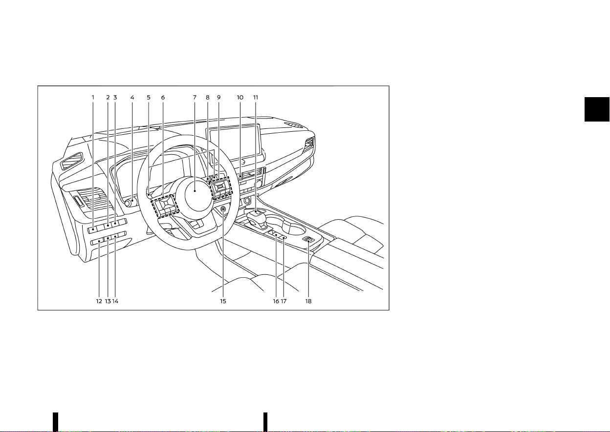
(67,1)
MEVT33A1-0F15EA1B-A7DB-45B6-808B-E4CBE71BB2BD
LEFT-HAND DRIVE (LHD) MODEL
MEVT33A1-2B00DBF7-EE42-421B-AF8E-1F5ECFA92E12
MWAA0463X
1. Headlight aiming control switch*
2. Steering Assist switch* (models with ProPI-
LOT Assist) or dynamic driver assistance
switch* (models without ProPILOT Assist)
3. Head Up Display (HUD) switch*
4. Headlight and turn signal switch/Fog light
switch
5. Paddle shifters
6. Steering-wheel-mounted controls (left side)
— Audio control*
— Vehicle information display control
7. Steering wheel
— Horn
8. Wiper and washer switch
9. Steering-wheel-mounted controls (right
side)
— Speed limiter switches*
— Cruise control switches*
— Intelligent Cruise Control (ICC) switches*
— ProPILOT Assist switches*
— Bluetooth® Hands-Free Phone System
switches*
— Voice Recognition system switch*
10. Hazard indicator flasher switch
11. Shift lever
— Continuously Variable Transmission (CVT)
12. Instrument brightness control
13. Stop/Start OFF switch
14. Power back door switch*
15. Push-button ignition switch
16. Parking brake switch
17. Automatic brake hold switch
18. Drive Mode Selector
*: where fitted
Instruments and controls 63
COCKPIT
COCKPIT
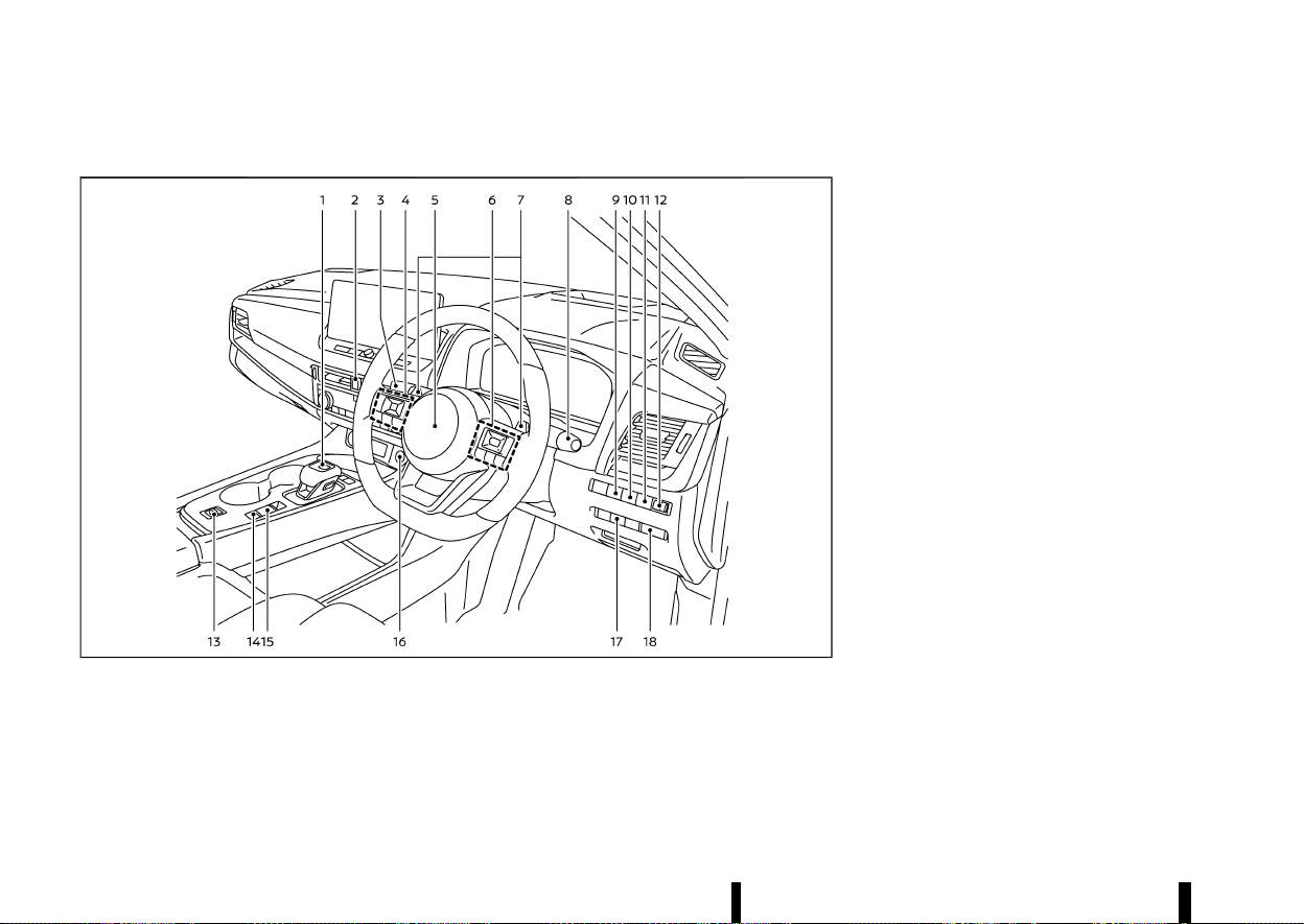
(68,1)
64 Instruments and controls
RIGHT-HAND DRIVE (RHD) MODEL
MEVT33A1-0D5DCB01-FA1E-47E2-BCA4-8DB307694C02
MWAA0413X
1. Shift lever
— Continuously Variable Transmission (CVT)
2. Hazard indicator flasher switch
3. Headlight and turn signal switch/Fog light
switch
4. Steering-wheel-mounted controls (left side)
— Audio control*
— Vehicle information display control
5. Steering wheel
— Horn
6. Steering-wheel-mounted controls (right
side)
— Speed limiter switches*
— Cruise control switches*
— Intelligent Cruise Control (ICC) switches*
— ProPILOT Assist switches*
— Bluetooth® Hands-Free Phone System
switches*
— Voice Recognition system switch*
7. Paddle shifters
8. Wiper and washer switch
9. Head Up Display (HUD) switch*
10. Steering Assist switch* (models with ProPI-
LOT Assist) or dynamic driver assistance
switch* (models without ProPILOT Assist)
11. Stop/Start OFF switch
12. Headlight aiming control switch*
13. Drive Mode Selector
14. Automatic brake hold switch
15. Parking brake switch
16. Push-button ignition switch
17. Power back door switch*
18. Instrument brightness control
*: where fitted
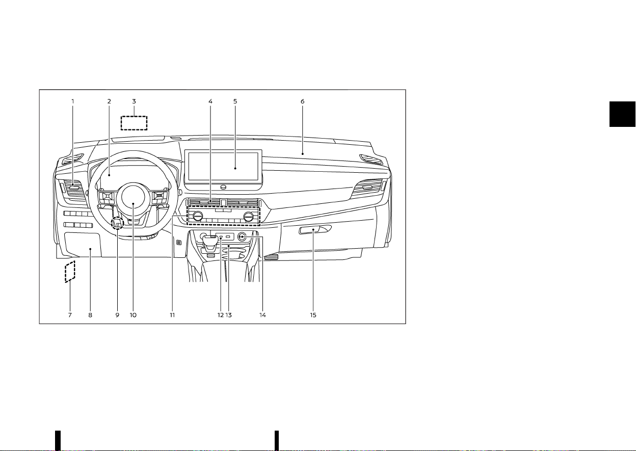
(69,1)
MEVT33A1-BFD2EC11-1644-45AC-88EF-F728562C8953
LEFT-HAND DRIVE (LHD) MODEL
MEVT33A1-F3259D13-17EA-4389-ABF3-429770A9AC8E
MWAA0414X
1. Side vent
2. Meters and gauges/Clock
3. Head Up Display (HUD)*
4. Centre vent
5. Audio system* or navigation system*
— Rear view Monitor*
— Intelligent Around View Monitor*
— Bluetooth® Hands-Free Phone System*
— Clock*
6. Front passenger supplemental air bag
7. Bonnet release handle
8. Fuse box cover
9. Tilt and telescopic steering lock lever
10. Driver supplemental front-impact air bag
11. Heater and air conditioner control
— Defogger switch
— Heated seat switches*
— Heated steering wheel switch*
— Heated windscreen*
12. USB (Universal Serial Bus) connection port(s)*
13. Wireless charger*
14. Power outlet
15. Glove box
*: where fitted
Instruments and controls 65
INSTRUMENT PANEL
INSTRUMENT PANEL

(70,1)
66 Instruments and controls
RIGHT-HAND DRIVE (RHD) MODEL
MEVT33A1-F8BA837A-D63E-49C6-8C86-FB21EFD952C8
MWAA0415X
1. Front passenger supplemental air bag
2. Centre vent
3. Audio system* or navigation system*
— Rear view Monitor*
— Intelligent Around View Monitor*
— Bluetooth® Hands-Free Phone System*
— Clock*
4. Head Up Display (HUD)*
5. Meters and gauges/Clock
6. Side vent
7. Fuse box cover
8. Glove box
9. Power outlet
10. Wireless charger*
11. USB (Universal Serial Bus) connection port(s)*
12. Heater and air conditioner control
— Defogger switch
— Heated seat switches*
— Heated steering wheel switch*
— Heated windscreen*
13. Tilt and telescopic steering lock lever
14. Driver supplemental front-impact air bag
15. Bonnet release handle
*: where fitted
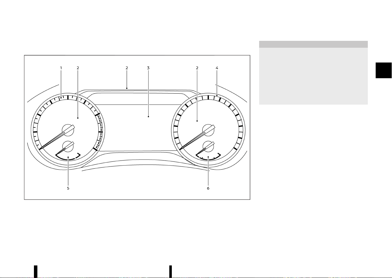
(71,1)
MEVT33A1-DF36AE97-4508-4B81-8D84-DB4C25F6792E
MODELS WITH ANALOG METER AND COLOUR DISPLAY
MEVT33A1-36C7F4DD-ECF8-44A2-BE63-80F62F544280
MWAA0409X
Example
1. Tachometer
2. Warning and indicator lights
3. Vehicle information display
— Odometer
4. Speedometer
5. Engine coolant temperature gauge
6. Fuel gauge
CAUTION
* For cleaning, use a soft cloth, dampened
with water. Never use a rough cloth,
alcohol, benzine, thinner or any kind of
solvent or paper towel with a chemical
cleaning agent. They will scratch or cause
discoloration to the lens.
* Do not spray any liquid such as water on
the meter lens. Spraying liquid may cause
the system to malfunction.
Instruments and controls 67
METERS AND GAUGES
METERS AND GAUGES
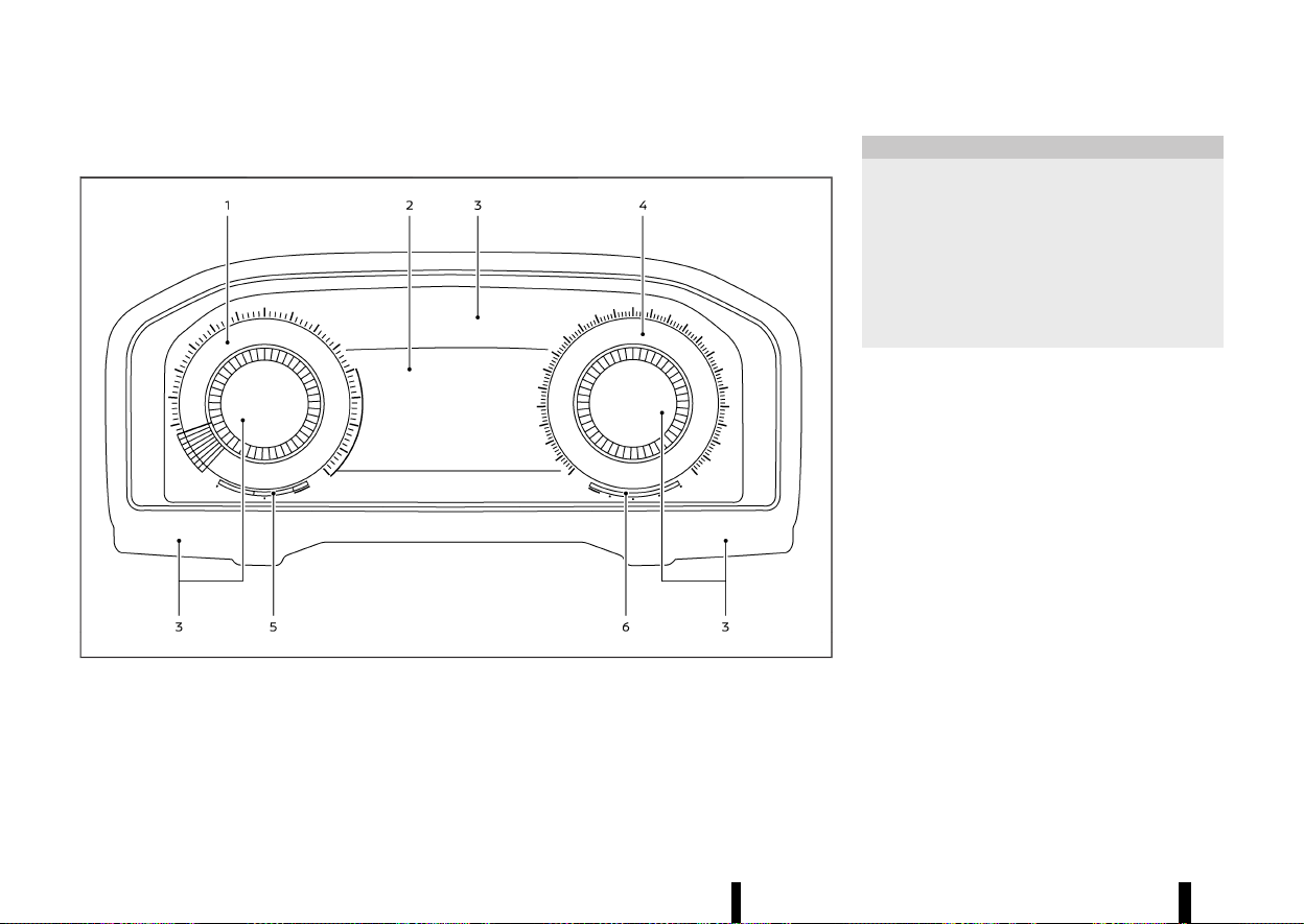
(72,1)
68 Instruments and controls
MODELS WITH FULL-SCREEN DISPLAY
MEVT33A1-FE71CC69-0EBA-4385-B419-50A06F5D4F29
MWAA0417X
1. Tachometer
2. Vehicle information display
— Odometer
3. Warning and indicator lights
4. Speedometer
5. Engine coolant temperature gauge
6. Fuel gauge
CAUTION
* For cleaning, use a soft cloth, dampened
with water. Never use a rough cloth,
alcohol, benzine, thinner or any kind of
solvent or paper towel with a chemical
cleaning agent. They will scratch or cause
discoloration to the lens.
* Do not spray any liquid such as water on
the meter lens. Spraying liquid may cause
the system to malfunction.
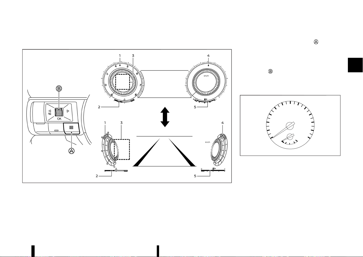
(73,1)
Changing the meter screen view (models with full-screen display)
MEVT33A1-48665970-36E4-455B-9AC2-8896884407FE
MWAC0939X
Example
1. Tachometer
2. Engine coolant temperature gauge
3. Personal Display
4. Speedometer
5. Fuel gauge
For models with full-screen display, the meter
screen view can be changed to expand the vehicle
information display area.
To change the meter screen view:
1. Push the shortcut menu button
on the left
side of the steering wheel.
[Shortcut Menu] appears on the vehicle in-
formation display area.
2. Select [Change Display View] by rotating the
scroll dial
and push it to change the view.
SPEEDOMETER AND ODOMETER
MEVT33A1-51A241D7-04C6-4D12-AE1B-0180C370F35E
Speedometer
MEVT33A1-BAC86101-A78F-4954-BFF9-E2BDCDA72736
MWAC0940X
Example
The speedometer indicates vehicle speed (km/h or
MPH (where fitted)).
Instruments and controls 69
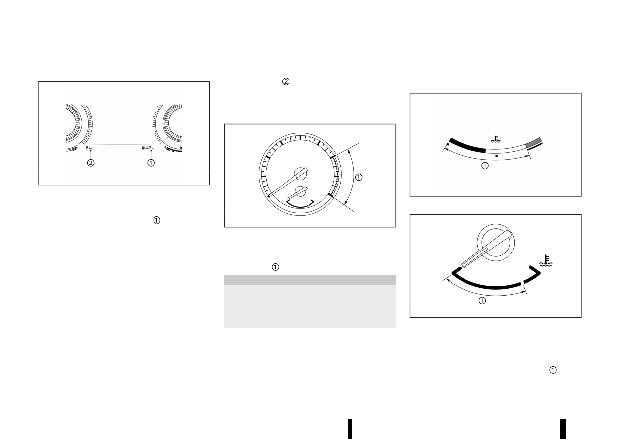
(74,1)
70 Instruments and controls
Distance to empty (dte)/ODOMETER
MEVT33A1-4875FEF0-726E-40B4-8040-2392D49E2AC4
MWAC0941X
Example
Distance to empty (dte):
The distance to empty (dte)
provides an
estimation of the distance that can be driven
before refuelling. The dte is constantly being
calculated, based on the amount of fuel in the fuel
tank and the actual fuel consumption.
The display is updated every 30 seconds.
The dte mode includes a low range warning
feature. If the fuel level is low, the warning is
displayed on the screen.
When the fuel level drops even lower, the dte
display will change to [———].
* If the amount of fuel added is small, the display
just before the ignition switch is placed in the
“OFF” position may continue to be displayed.
* When driving uphill or rounding curves, the
fuel in the tank shifts, which may momentarily
change the display.
Odometer:
The odometer
is displayed in the vehicle
information display to display the total distance
the vehicle has been driven.
TACHOMETER
MEVT33A1-215DFAC7-AA25-4799-B76A-5C7F24514E30
MWAC0942X
Example
The tachometer indicates engine speed in revolu-
tions per minute (RPM). Do not rev the engine into
the red zone
.
CAUTION
When engine speed approaches the red zone,
shift to a higher gear or reduce engine speed.
Operating the engine in the red zone may
cause serious engine damage.
ENGINE COOLANT TEMPERATURE
GAUGE
MEVT33A1-34DD45D3-B4F2-44CD-AAC9-21491CEBB243
MWAC0955X
Full-screen model
MWAC0943X
Analog model
The engine coolant temperature gauge indicates
the engine coolant temperature.
The engine coolant temperature is normal when
the gauge needle points within the zone
shown
in the illustration.
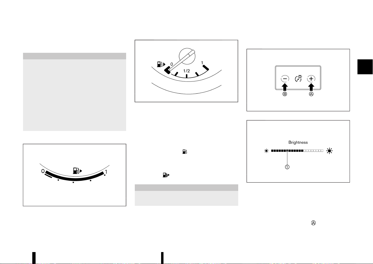
(75,1)
The engine coolant temperature will vary with the
outside air temperature and driving conditions.
CAUTION
* If the gauge indicates the engine coolant
temperature is near the hot (H) end of the
normal range, reduce vehicle speed to
decrease the temperature.
* If the gauge is over the normal range, stop
the vehicle as soon as safely possible and
let the engine idle.
* If the engine is overheated, continued
operation of the vehicle may seriously
damage the engine. (See “If your vehicle
overheats” (P.411) for immediate action
required.)
FUEL GAUGE
MEVT33A1-353F5508-A471-4C58-AF18-C779D3376019
MWAC0970X
Full-screen model
MJVI0640X
Analog model
The fuel gauge indicates the approximate fuel level
in the tank when the ignition switch is in the ON
position.
The gauge may move slightly during braking,
turning, accelerating, or going up and down hills
due to movement of fuel in the tank.
The low fuel warning
appears on the vehicle
information display when the fuel level in the tank
is getting low. Refuel as soon as it is convenient,
preferably before the gauge reads 0 (empty).
The arrow,
, indicates the fuel-filler lid is
located on the right side of the vehicle.
CAUTION
Refuel before the gauge reads the empty (0)
position.
INSTRUMENT BRIGHTNESS CONTROL
MEVT33A1-144F9E3B-4FD3-48D2-9EB4-CCA14CF254B6
MWAC0566X
MWAC0489X
The instrument brightness control switch can be
operated when the ignition switch is in the ON
position. When the switch is operated, the vehicle
information display switches to the brightness
adjustment mode.
Push the + side of the switch
to brighten the
Instruments and controls 71
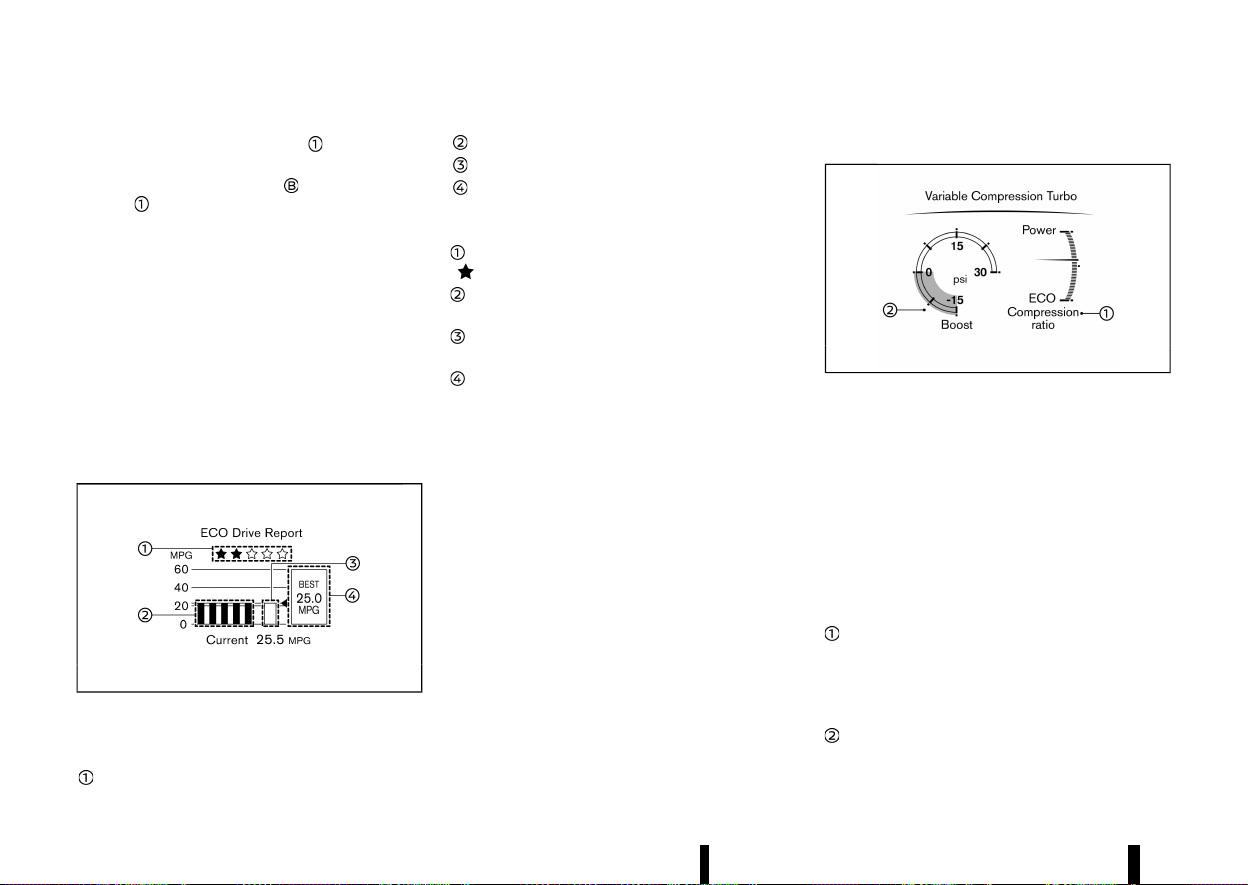
(76,1)
72 Instruments and controls
instrument panel lights. The bar moves to the
right side.
Push the - side of the switch
to dim the lights.
The bar
moves to the left side.
The vehicle information display returns to the
normal display when the instrument brightness
control switch is not operated for more than 5
seconds.
CONTINUOUSLY VARIABLE TRANSMIS-
SION (CVT) POSITION INDICATOR
MEVT33A1-155741F1-1673-4782-A651-BABD38DC6C57
The Continuously Variable Transmission (CVT)
position indicator indicates the shift lever position
when the ignition switch is in the ON position. (See
“17. Continuously Variable Transmission (CVT) posi-
tion indicator” (P.95).)
ECO DRIVE REPORT
MEVT33A1-0AC9BFA4-8D2C-4F68-967B-4202BE84C4E0
MWAC0513X
Example
When the ignition switch is placed in the ON or
“OFF” position, the ECO Drive Report is displayed.
ECO evaluation
Previous 5 times (History)
Current fuel economy
Best fuel economy
The result of ECO evaluation is displayed when the
vehicle is driven for about 10 minutes or more.
: The more economically you drive, the more
appear.
: The average fuel economy for the previous 5
times will be displayed.
: The average fuel economy since the last reset
will be displayed.
: The best fuel economy of the past history will
be displayed.
When the [ECO Advice Adjust Tyre Pressures]
message appears in the ECO Drive Report, the
display can be switched to the Tyre Pressures
display by pushing the scroll dial on the steering
wheel to show an additional message.
VARIABLE COMPRESSION TURBO
MEVT33A1-8DD78A7C-66D9-492C-AEC1-CE437BE4BD7A
MWAC0971X
Example
Your engine is equipped with a variable compres-
sion ratio system called “Variable Compression
Turbo”. This system can vary the engine compres-
sion ratio continuously.
According to driving conditions, the system applies
optimum compression ratio automatically to
achieve both high output and high fuel economy
efficiency.
This is not a physical gauge. It is a display option in
the vehicle information display that can be
selected. (See “Vehicle information display” (P.81).)
Compression ratio status display
Displays the status of compression ratio controlled
by Variable Compression Turbo. The lowest com-
pression ratio (8:1) and the highest (14:1) are
displayed as “Power” and ”Eco” respectively.
Turbo charger boost pressure gauge
Displays the turbo charger boost pressure. The

(77,1)
unit for the gauge can be changed in the [Settings]
menu. (See “[Unit/Language]” (P.89).)
NOTE:
Under some conditions, the compression ratio
may not change. This is not a malfunction of the
system.
CAUTION
If the Variable Compression Turbo becomes
malfunction, the Malfunction Indicator Light
(MIL) may come on. For additional information,
see “Malfunction Indicator Light (MIL)” (P.79).
Instruments and controls 73
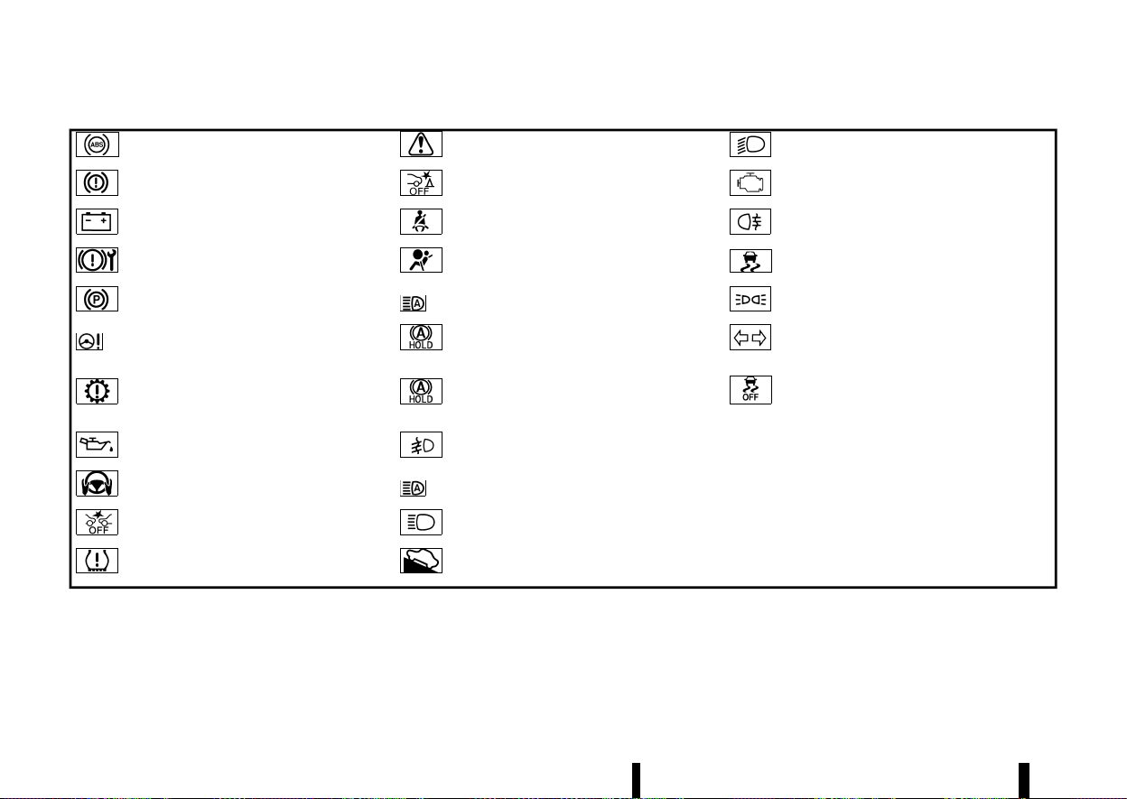
(78,1)
74 Instruments and controls
MEVT33A1-0AD04023-03AE-4553-915A-04F0D33BD0B8
Anti-lock Braking System (ABS) warning
light
Master warning light
Low beam indicator light*
Brake warning light (red)
Rear Automatic Braking (RAB) system OFF
warning light*
Malfunction Indicator Light (MIL)
Charge warning light Seat belt warning light and chime
Rear fog light indicator light
Electronic parking brake system warning
light
Supplemental Restraint System (SRS) air bag
warning light
Slip indicator light
Electronic parking brake warning light Adaptive LED headlight indicator light*
Small light indicator light
Electric power steering warning light Automatic brake hold indicator light (white)
Turn signal/hazard indicator lights
Electric shift control system warning light Automatic brake hold indicator light (green)
Vehicle Dynamic Control (VDC) off indicator
light (except for Europe)/Electronic Stability
Programme (ESP) off indicator light (for
Europe)
Engine oil pressure warning light Front fog light indicator light*
*: where fitted
Hands OFF warning light* High beam assist indicator light*
Intelligent Emergency Braking with Pedes-
trian Detection system OFF warning light
High beam indicator light
Low tyre pressure warning light Hill start assist system indicator light
WARNING LIGHTS, INDICATOR
LIGHTS AND AUDIBLE REMINDERS
WARNING LIGHTS, INDICATOR LIGHTS AND AUDIBLE REMINDERS
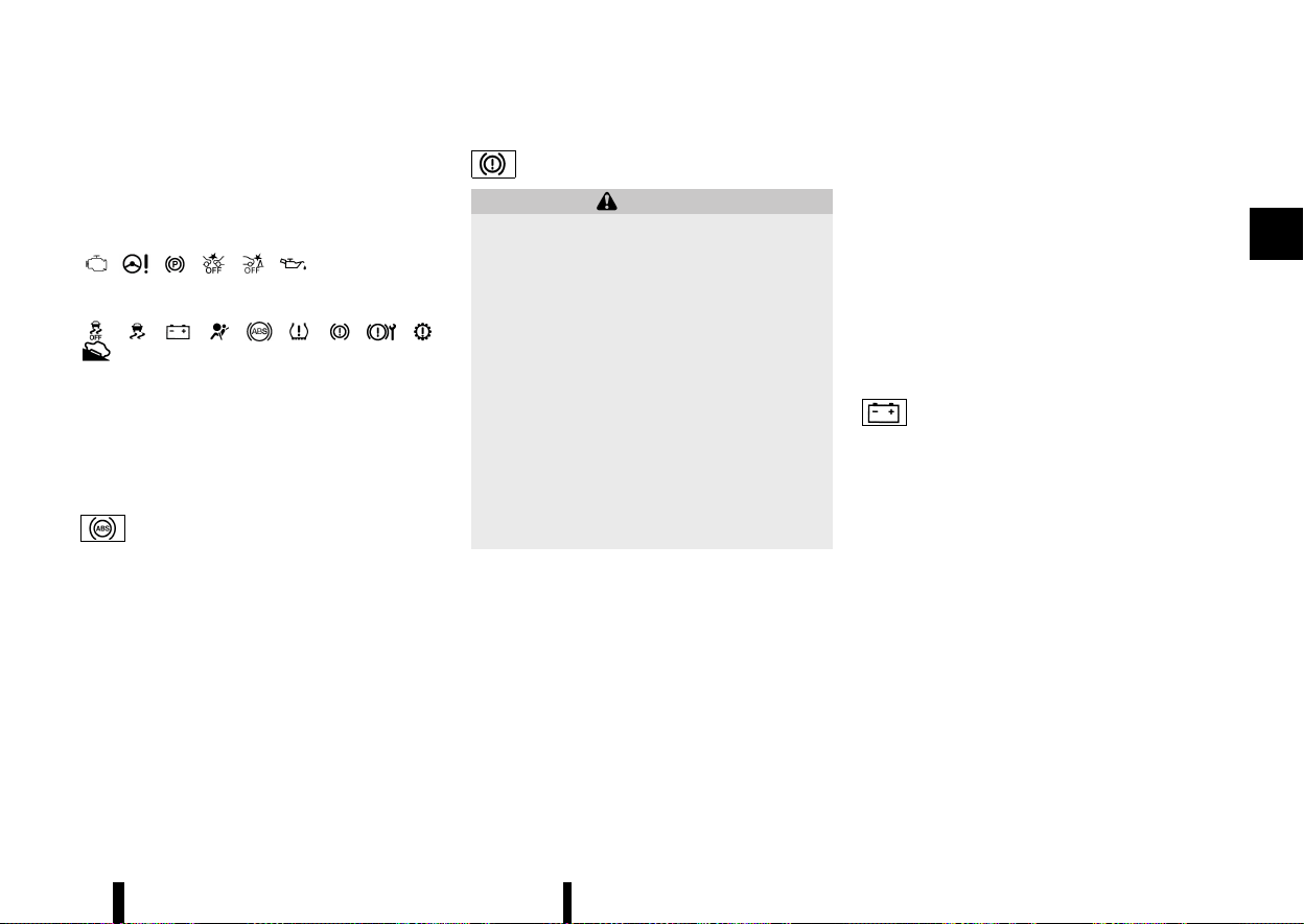
(79,1)
CHECKING LIGHTS
MEVT33A1-C22DF306-092D-4583-8CB3-A6AC7219AD77
With all doors closed, apply the parking brake,
fasten the seat belts and place the ignition switch
in the ON position without starting the engine. The
following lights (where fitted) will come on:
, , , , ,
The following lights (where fitted) come on briefly
and then go off:
, , , , , , , , ,
.
If any light does not come on or operates in a way
other than described, it may indicate a burned-out
bulb and/or a system malfunction. Have the
system checked, and if necessary repaired, by a
NISSAN dealer or qualified workshop promptly.
WARNING LIGHTS
MEVT33A1-CB655EAC-D167-42F6-996B-BF220E007B1D
Anti-lock Braking System (ABS) WARNING LIGHT
MEVT33A1-94D8EF69-CB1A-45F8-A40A-491B3BA0299B
When the ignition switch is in the ON position, the
Anti-lock Braking System (ABS) warning light
illuminates and then turns off. This indicates the
ABS is operational.
If the ABS warning light illuminates while the
engine is running, or while driving, it may indicate
the ABS is not functioning properly. Have the
system checked by a NISSAN dealer or qualified
workshop promptly.
If an ABS malfunction occurs, the anti-lock func-
tion is turned off. The brake system then operates
normally, but without anti-lock assistance. (See
“Brake system” (P.389).)
Brake warning light
MEVT33A1-21F0780E-8D92-4B48-8AC5-495231853BE1
WARNING
* If the brake fluid level is below the mini-
mum mark on the brake fluid reservoir, do
not drive the vehicle until the brake system
has been checked by a NISSAN dealer or
qualified workshop.
* Even if you judge it to be safe, have your
vehicle towed because driving it could be
dangerous.
* Depressing the brake pedal without the
engine running and/or with a low brake
fluid level could increase the stopping
distance and require greater pedal travel
distance and effort.
The brake warning light indicates a low brake
fluid level of the brake system and an Anti-lock
Braking System (ABS) malfunction.
Low brake fluid warning indicator:
When the ignition switch is placed in the ON
position, the brake warning light illuminates, and
then turns off.
If the brake warning light illuminates while the
engine is running, or while driving, and the parking
brake is released, it may indicate the brake fluid
level is low.
When the brake warning light illuminates while
driving, stop the vehicle safely as soon as possible.
Stop the engine and check the brake fluid level. If
the brake fluid level is at the minimum mark, add
brake fluid as necessary. (See “Brake fluid” (P.434).)
Anti-lock Braking System (ABS) WARNING INDI-
CATOR:
When the parking brake is released and the brake
fluid level is sufficient, if both the brake warning
light and the Anti-lock Braking System (ABS)
warning light illuminate, it may indicate the ABS
is not functioning properly. Have the brake system
checked, and if necessary repaired, by a NISSAN
dealer or qualified workshop promptly. (See “Anti-
lock Braking System (ABS) warning light” (P.75).)
Charge warning light
MEVT33A1-DAF8C1DB-0D65-48DD-A5B2-B2111E95A603
When the ignition switch is in the ON position, the
charge warning light illuminates and then turns
off. This indicates the charging system is opera-
tional.
If the charge warning light illuminates while the
engine is running, or while driving, it may indicate
the charging system is not functioning properly
and may need servicing.
When the charge warning light illuminates while
driving, stop the vehicle safely as soon as possible.
Stop the engine and check the starter generator
belt. If the starter generator belt is loose, broken or
missing, the charging system needs repair. (See
“Drive belt” (P.432).)
If the starter generator belt appears to be func-
tioning correctly but the charge warning light
remains illuminated, have the charging system
checked by a NISSAN dealer or qualified workshop
promptly.
Instruments and controls 75
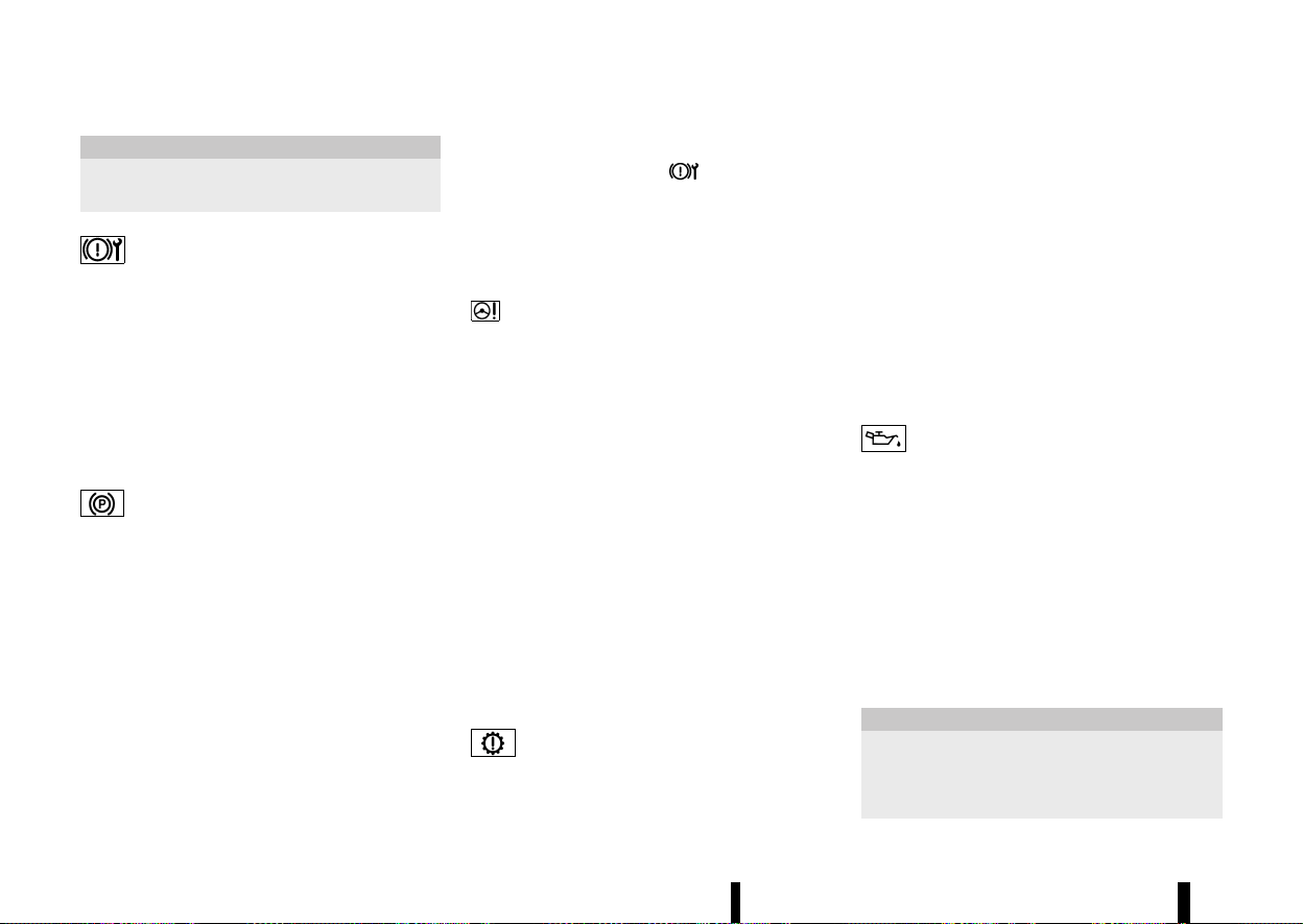
(80,1)
76 Instruments and controls
CAUTION
Do not continue driving if the starter generator
belt is loose, broken or missing.
Electronic parking brake system warning light
MEVT33A1-70F1E606-FA0F-4929-BEC6-12899B01A5C9
When the ignition switch is in the ON position, the
electronic parking brake system warning light
illuminates and then turns off.
The electronic parking brake system warning light
functions for the electronic parking brake system.
If the warning light illuminates, it may indicate that
the electronic parking brake system is not func-
tioning properly. Have the brake system checked,
and if necessary repaired, by a NISSAN dealer or
qualified workshop promptly.
Electronic parking brake warning light
MEVT33A1-BD89141F-C2E9-445B-A775-9855975F4EB2
The electronic parking brake warning light indi-
cates that the electronic parking brake system is
operating.
When the ignition switch is placed in the ON
position, the electronic parking brake warning
light illuminates. When the engine is started and
the parking brake is released, the warning light
turns off.
If the parking brake is not released, the electronic
parking brake warning light remains on. Be sure
that the electronic parking brake warning light has
turned off before driving. (See “Parking brake”
(P.171).)
If the electronic parking brake warning light
illuminates or flashes while the electronic parking
brake system warning light
illuminates, it may
indicate that the electronic parking brake system
is not functioning properly. Have the electronic
parking brake system checked, and if necessary
repaired, by a NISSAN dealer or qualified workshop
promptly.
Electric power steering warning light
MEVT33A1-741C61E1-031B-4E18-B5E7-CDE0E0CE451F
When the ignition switch is in the ON position, the
electric power steering warning light illuminates.
After starting the engine, the electric power
steering warning light turns off. This indicates the
electric power steering is operational.
If the electric power steering warning light illumi-
nates while the engine is running, it may indicate
the electric power steering is not functioning
properly and may need servicing. Have the electric
power steering checked by a NISSAN dealer or
qualified workshop.
When the electric power steering warning light
illuminates with the engine running, the power
assist to the steering will cease operation but you
will still have control of the vehicle. At this time,
greater steering efforts are required to operate the
steering wheel, especially in sharp turns and at low
speeds.
(See “Electric power steering” (P.389).)
Electric shift control system warning light
MEVT33A1-452B1CD9-A5FB-47A2-A505-F1250D9B1D3A
When the ignition switch is in the ON position, the
electric shift control system warning light illumi-
nates, and then turns off. This indicates the electric
shift control system is operational.
The electric shift control system warning light
illuminates when a malfunction occurs in the
electric shift control system. When the master
warning light illuminates, the chime sounds and
the following message is displayed in the vehicle
information display: [Apply parking brake].
When the ignition switch is placed in the “OFF”
position, the chime sounds continuously. Ensure
the parking brake is applied.
Have the system checked by a NISSAN dealer or
qualified workshop.
Engine oil pressure warning light
MEVT33A1-0E186C13-021C-41D3-B6C5-037ED653F41D
This light warns of low engine oil pressure. When
the ignition switch is in the ON position, the engine
oil pressure warning light illuminates. After starting
the engine, the engine oil pressure warning light
turns off. This indicates that the oil pressure
sensors in the engine are operational.
If the engine oil pressure warning light illuminates
or blinks while the engine is running, it may
indicate that the engine oil pressure is low.
Stop the vehicle safely as soon as possible. Stop
the engine immediately and call a NISSAN dealer or
qualified workshop.
CAUTION
* Running the engine with the engine oil
pressure warning light illuminated could
cause serious damage to the engine.
* The engine oil pressure warning light is not
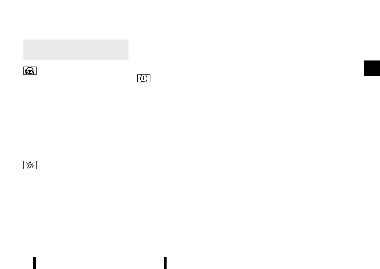
(81,1)
designed to indicate a low oil level. The oil
level should be checked using the dipstick.
(See “Engine oil” (P.430).)
Hands OFF warning light (where fitted)
MEVT33A1-B6E942B2-231A-4173-8127-3F139D0ED949
When the Steering Assist is activated, it monitors
the driver’s steering wheel operation. If the steer-
ing wheel is not operated or the driver takes his/
her hands off the steering wheel for a period of
time, the warning light illuminates. If the driver
does not operate the steering wheel after the
warning light has been illuminated, an audible alert
sounds and the warning flashes in the vehicle
information display, followed by a quick brake
application to request the driver to take control
of the vehicle again. If the driver remains unre-
sponsive, the vehicle will automatically turn on the
hazard lights and slow to a complete stop. (See
“Steering Assist” (P.351).)
Intelligent Emergency Braking with Pe-
destrian Detection system OFF warning light
MEVT33A1-197910F0-AE83-4B9D-82D9-A4BA89717941
When the ignition switch is in the ON position, the
Intelligent Emergency Braking with Pedestrian
Detection system OFF warning light illuminates.
After starting the engine, the Intelligent Emer-
gency Braking with Pedestrian Detection system
OFF warning light turns off.
This light illuminates when the Intelligent Emer-
gency Braking with Pedestrian Detection system is
set to OFF on the vehicle information display.
If the light illuminates or flashes when the Intelli-
gent Emergency Braking with Pedestrian Detec-
tion system is ON, it may indicate that the system
is unavailable. See “Intelligent Emergency Braking
with Pedestrian Detection system” (P.359) or “In-
telligent Forward Collision Warning” (P.369).
Low tyre pressure warning light
MEVT33A1-E9120556-C164-4940-BED7-7C971399C735
Your vehicle is equipped with a Tyre Pressure
Monitoring System (TPMS) that monitors the tyre
pressure of all tyres.
The low tyre pressure warning light warns of low
tyre pressure or indicates that the TPMS is not
functioning properly.
After the ignition switch is placed in the ON
position, this light illuminates for about 1 second
and turns off.
Low tyre pressure warning:
If the vehicle is being driven with low tyre pressure,
the warning light will illuminate. The [Low Tyre
Pressure] warning also appears in the vehicle
information display.
When the low tyre pressure warning light illumi-
nates, you should stop and adjust the tyre
pressure to the recommended COLD tyre pressure
shown on the tyre placard. The low tyre pressure
warning light does not automatically turn off when
the tyre pressure is adjusted. After the tyre is
inflated to the recommended pressure, reset the
tyre pressures registered in your vehicle and then
drive the vehicle at speeds above 25 km/h (16
MPH). These operations are required to activate
the TPMS and turn off the low tyre pressure
warning light. Use a tyre pressure gauge to check
the tyre pressure.
The [Low Tyre Pressure] warning is active as long
as the low tyre pressure warning light remains
illuminated.
TPMS resetting must be also performed after a
tyre or a wheel is replaced, or the tyres are rotated.
Depending on a change in the outside tempera-
ture, the low tyre pressure warning light may
illuminate even if the tyre pressure has been
adjusted properly. Adjust the tyre pressure to the
recommended COLD tyre pressure again when the
tyres are cold, and reset the TPMS.
If the low tyre pressure warning light still continues
to illuminate after the resetting operation, it may
indicate that the TPMS is not functioning properly.
Have the system checked by a NISSAN dealer or
qualified workshop.
For additional information, see “Vehicle informa-
tion display” (P.81), “Tyre Pressure Monitoring
System (TPMS)” (P.240) and “Tyre Pressure Mon-
itoring System (TPMS)” (P.405).
TPMS malfunction:
If the TPMS is not functioning properly, the low tyre
pressure warning light will flash for approximately
1 minute when the ignition switch is placed in the
ON position. The light will remain on after the 1
minute. Have the system checked by a NISSAN
dealer or qualified workshop. The [Low Tyre
Pressure] warning does not appear if the low tyre
pressure warning light illuminates to indicate a
TPMS malfunction.
Instruments and controls 77
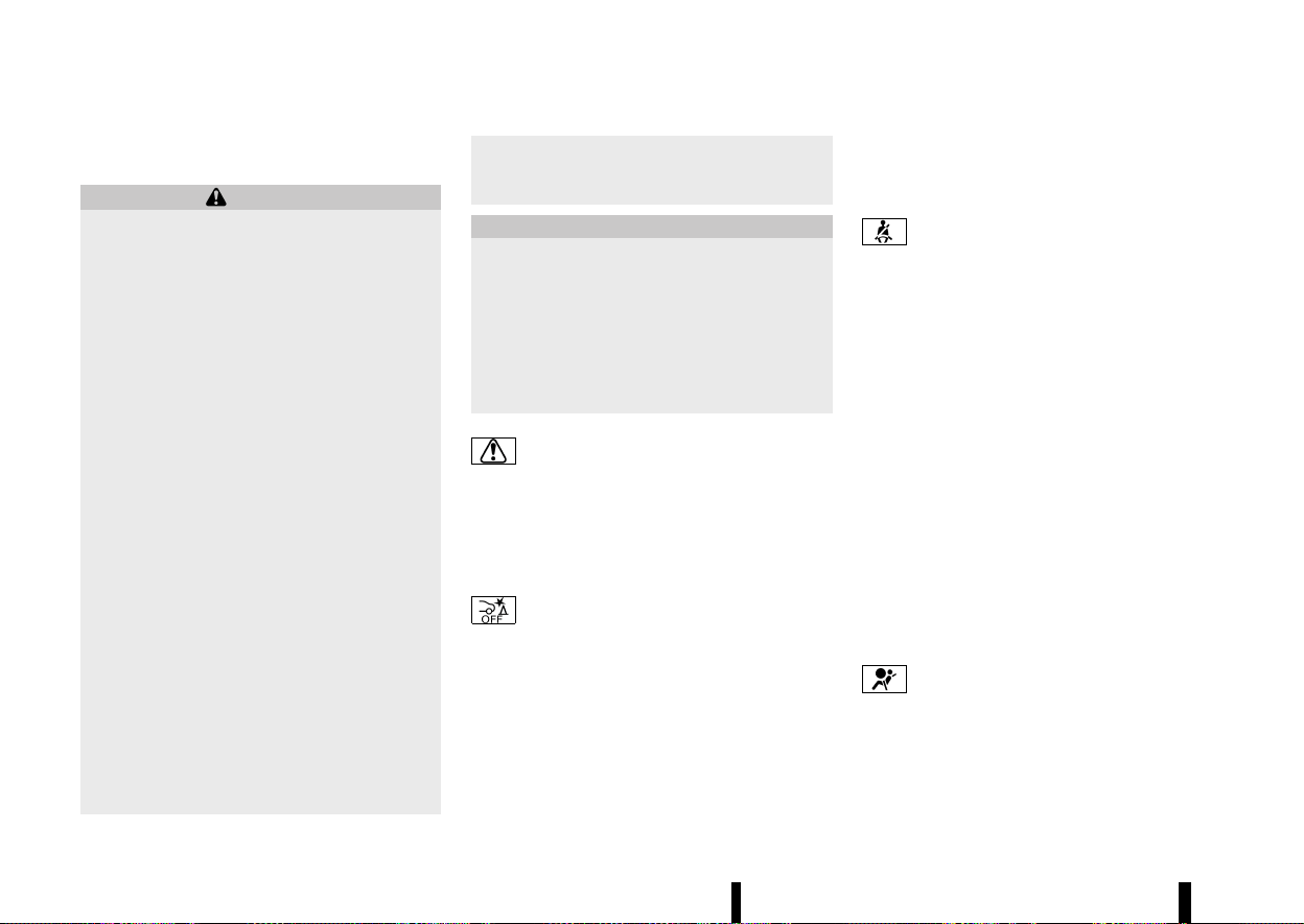
(82,1)
78 Instruments and controls
For additional information, see “Tyre Pressure
Monitoring System (TPMS)” (P.240).
WARNING
* If the light does not illuminate with the
ignition switch placed in the ON position,
have the vehicle checked by a NISSAN
dealer or qualified workshop as soon as
possible.
* If the light illuminates while driving, avoid
sudden steering manoeuvres or abrupt
braking, reduce vehicle speed, pull off the
road to a safe location and stop the vehicle
as soon as possible. Driving with under-
inflated tyres may permanently damage
the tyres and increase the likelihood of
tyre failure. Serious vehicle damage could
occur and may lead to an accident and
could result in serious personal injury.
Check the tyre pressure for all four tyres.
Adjust the tyre pressure to the recom-
mended COLD tyre pressure shown on the
tyre placard to turn the low tyre pressure
warning light OFF. If the light still illumi-
nates while driving after adjusting the tyre
pressure, a tyre may be flat or the TPMS
may be malfunctioning. If you have a flat
tyre, repair it with an emergency tyre
puncture repair kit as soon as possible. If
no tyre is flat and all tyres are properly
inflated, have the vehicle checked by a
NISSAN dealer or qualified workshop.
* After adjusting the tyre pressure, be sure
to reset the TPMS. Otherwise, the TPMS will
not warn of low tyre pressure.
* Replacing tyres with those not originally
specified by NISSAN could affect the prop-
er operation of the TPMS.
CAUTION
* The TPMS is not a substitute for the regular
tyre pressure check. Be sure to check the
tyre pressure regularly.
* If the vehicle is being driven at speeds of
less than 25 km/h (16 MPH), the TPMS may
not operate correctly.
* Be sure to install the specified size of tyres
to the four wheels correctly.
Master warning light
MEVT33A1-FE60ECDF-B81F-42DA-9241-D02C91924B2B
When the ignition switch is in the ON position, the
master warning light illuminates if a warning
message appears in the vehicle information dis-
play.
See “Vehicle information display” (P.81).
Rear Automatic Braking (RAB) SYS-
TEM OFF WARNING LIGHT (where fitted)
MEVT33A1-718B0657-5622-4110-BB3D-F05C70A6CDFF
This light comes on when the ignition switch is
placed in the ON position. It turns off after the
engine is started.
This light illuminates when the RAB system is
turned off with the shift position in R (Reverse) in
the vehicle information display.
If the light illuminates when the RAB system is on, it
may indicate that the system is unavailable. For
additional information, see “Rear Automatic Brak-
ing (RAB) (where fitted)” (P.377).
Seat belt warning light and chime
MEVT33A1-AFBA2490-005D-4A00-BD76-5FE032801AE0
The seat belt warning light and chime remind you
to fasten the seat belts.
The light illuminates whenever the ignition switch
is placed in the ON position, and will remain
illuminated until the seat belts are fastened.
The seat belt warning light for the front passenger
will illuminate if the seat belt is not fastened when
the front passenger’s seat is occupied.
When the vehicle speed exceeds 15 km/h (10 MPH),
the light will continue to blink and the chime will
sound for about 95 seconds unless the driver’s
seat belt is securely fastened.
When the vehicle speed exceeds 15 km/h (10 MPH),
if the front passenger’s seat or rear seat is
occupied, the light will continue to blink and the
chime will sound for about 95 seconds unless the
front passenger’s seat belt or rear seat belt is
securely fastened.
(See “Seat belts” (P.28).)
Supplemental Restraint System
(SRS) AIR BAG WARNING LIGHT
MEVT33A1-94669243-2339-4D53-AF63-5FF94E523E50
When the ignition switch is in the ON position, the
Supplemental Restraint System (SRS) air bag
warning light illuminates for about 7 seconds and
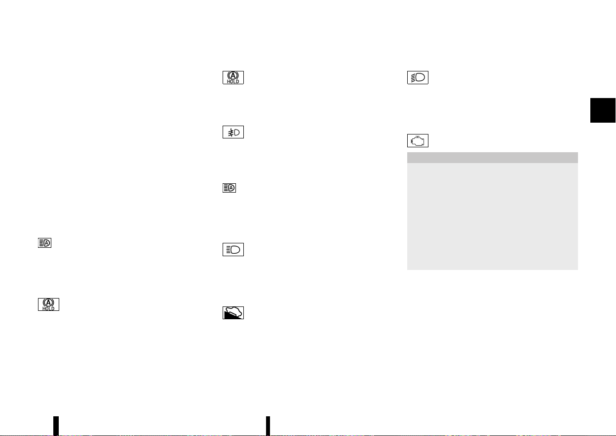
(83,1)
then turns off. This indicates the SRS air bag
system is operational.
If any of the following conditions occur, the SRS air
bag system and pre-tensioner seat belt need
servicing. Have the system checked, and if neces-
sary repaired, by a NISSAN dealer or qualified
workshop promptly.
* The SRS air bag warning light remains illumi-
nated after about 7 seconds.
* The SRS air bag warning light does not
illuminate at all.
Unless checked and repaired, the SRS air bag
system and/or pre-tensioner seat belt may not
function properly. (See “Supplemental Restraint
System (SRS)” (P.47).)
INDICATOR LIGHTS
MEVT33A1-E36F797E-35E7-4C33-8533-A9DCFC30B452
Adaptive LED headlight indicator light (where fitted)
MEVT33A1-FB41EEFA-3A53-4510-986B-9B075E635AF4
The adaptive LED headlight indicator light illumi-
nates when the adaptive LED headlight system is
turned on and it is operational. (See “Adaptive LED
headlight (where fitted)” (P.110).)
Automatic brake hold indicator light (white)
MEVT33A1-9A225898-36AF-4F11-9E3C-779320E6F052
Automatic brake hold indicator light (white) illumi-
nates when Automatic brake hold system is on
standby. (See “Automatic brake hold” (P.173).)
Automatic brake hold indicator light (green)
MEVT33A1-BC32B9F0-16A1-4FCA-8CB3-27CBACB29523
Automatic brake hold indicator light (green) illu-
minates when Automatic brake hold system is
operating. (See “Automatic brake hold” (P.173).)
Front fog light indicator light (where fitted)
MEVT33A1-ECA6061B-E0DA-42FF-A867-06F30FCFAD0D
The front fog light indicator light illuminates when
the front fog lights are on. (See “Fog light switch”
(P.115).)
High beam assist indicator light (where fitted)
MEVT33A1-F2C083A7-51BF-4040-B37C-A983373F330D
The high beam assist indicator light illuminates
when the high beam assist system is turned on
and it is operational. (See “High beam assist (where
fitted)” (P.109).)
High beam indicator light
MEVT33A1-849B231E-AF14-45BE-A788-A0C55B5A4C93
The high beam indicator light illuminates when the
headlight high beam is on. The indicator turns off
when the low beam is selected. (See “Headlight
and turn signal switch” (P.108).)
Hill start assist system indicator light
MEVT33A1-6124AF68-9B1F-443D-8C30-55F025CA2479
When the ignition switch is in the "ON" position,
the hill start assist system indicator light illumi-
nates and then turns off.
This light illuminates when the hill start assist
system is operating.
See “Hill Start Assist system” (P.394).
Low beam indicator light
MEVT33A1-9D853A41-DBB2-4A6E-8E31-78C3431071C6
The low beam indicator light illuminates when the
headlight low beam is on. The indicator turns off
when the high beam is selected. (See “Headlight
and turn signal switch” (P.108).)
Malfunction Indicator Light (MIL)
MEVT33A1-3B681144-EF74-4505-9B69-EFF12ED397F0
CAUTION
* Continuing vehicle operation without
proper servicing of the emission control
system and/or CVT system could lead to
poor driveability, reduced fuel economy,
and damage to the emission control sys-
tem, which may affect the vehicle’s war-
ranty coverage.
* Incorrect setting of the emission control
system may lead to non-compliance of
local and national emission laws and
regulations.
When the ignition switch is in the ON position, the
Malfunction Indicator Light (MIL) illuminates. After
starting the engine, the MIL turns off. This indicates
that the engine control system is operational.
When the ignition switch is in the ON position,
sometimes the MIL may illuminate for 20 seconds
and then blink for 10 seconds, without the engine
running. This is due to a function of checking the
emission control system, and it is not a malfunc-
tion. After a few normal drives, this function will not
occur and the MIL stays illuminated with the
ignition switch in the ON position.
Instruments and controls 79
(84,1)
80 Instruments and controls
If the MIL illuminates while the engine is running, it
may indicate that the engine control system and/
or CVT system is not functioning properly and may
need servicing. Have the vehicle checked, and if
necessary repaired, by a NISSAN dealer or qualified
workshop promptly.
If the MIL blinks while the engine is running, it may
indicate a potential malfunction in the engine
control system and/or CVT system. In this case,
the engine control system and/or CVT system may
not function properly and may need servicing.
Have the system checked, and if necessary re-
paired, by a NISSAN dealer or qualified workshop
promptly.
Precautions:
To reduce or avoid possible damage to the engine
control system and/or CVT system when the MIL
blinks:
* Avoid driving at speeds above 70 km/h (43
MPH).
* Avoid sudden acceleration or deceleration.
* Avoid going up steep uphill grades.
* Avoid carrying or towing unnecessary loads.
Rear fog light indicator light
MEVT33A1-77FFDDB6-B0C9-4759-98FE-8C29F4458A8B
The rear fog light indicator light illuminates when
the rear fog light is on. (See “Fog light switch”
(P.115).)
Slip indicator light
MEVT33A1-49E24159-6B65-4CE1-B634-94370CE76A1E
When the ignition switch is in the ON position, the
slip indicator light illuminates and then turns off.
The light will blink when the Vehicle Dynamic
Control (VDC)/Electronic Stability Programme
(ESP) system or the traction control system is
operating, thus alerting the driver that the vehicle
is nearing its traction limits. The road surface may
be slippery.
If the light illuminates while the VDC/ESP system is
on, this light alerts the driver to the fact that the
VDC/ESP system’s fail-safe mode is operating, for
example the VDC/ESP system may not be func-
tioning properly. Have the system checked, and if
necessary repaired, by a NISSAN dealer or qualified
workshop promptly. If a malfunction occurs in the
system, the VDC/ESP system function will be
cancelled but the vehicle is still driveable. For
additional information, see “Vehicle Dynamic Con-
trol (VDC)/Electronic Stability Programme (ESP)
system” (P.391) of this manual.
Small light indicator light
MEVT33A1-B9DA9F59-94DD-479E-A4ED-F9B3237B5784
This indicator illuminates when the headlight
switch is turned to the “AUTO”,
or
position and the front clearance lights, rear
combination lights, number plate lights or head-
lights are on. The indicator turns off when these
lights are turned off.
Turn signal/hazard indicator lights
MEVT33A1-938BCB58-C7D0-4656-B2E2-A3F2D5C472C5
The turn signals/hazard indicator lights blink when
the turn signal switch lever or hazard indicator
flasher switch is ON. (See “Headlight and turn
signal switch” (P.108) or “Hazard warning flasher
switch” (P.404).)
Vehicle Dynamic Control (VDC) OFF INDICATOR
LIGHT (except for Europe)/ELECTRONIC STABILITY
PROGRAMME (ESP) OFF INDICATOR LIGHT (for Europe)
MEVT33A1-5708F032-0868-4A79-BBAB-8EBEC2356AFE
The light comes on when the VDC/ESP is turned
OFF. This indicates that the VDC/ESP system and
traction control system are not operating.
Turn the VDC/ESP on using the vehicle information
display, or restart the engine and the system will
operate normally. (See “Vehicle Dynamic Control
(VDC)/Electronic Stability Programme (ESP) sys-
tem” (P.391).)
The light also comes on when placing the ignition
switch in the ON position. The light will turn off
after about 2 seconds if the system is operational.
If the light stays on or comes on along with the
indicator light while you are driving, have the
system checked by a NISSAN dealer or qualified
workshop.
WARNING
The VDC/ESP should remain on unless freeing
a vehicle from mud or snow.
While the VDC/ESP system is operating, you might
feel a slight vibration or hear the system working

(85,1)
when starting the vehicle or accelerating, but this
is not a malfunction.
AUDIBLE REMINDERS
MEVT33A1-42904A1A-6A75-4B8C-8F34-6D9818D98A82
Brake pad wear warning
MEVT33A1-EF2EB7E0-B227-4E63-9DC8-B730CC13FB1B
The disc brake pads have audible wear warnings.
When a brake pad requires replacement, it will
make a high pitched scraping sound when the
vehicle is in motion. This scraping sound will first
occur only when the brake pedal is depressed.
After more wear of the brake pad, the sound will
always be heard even if the brake pedal is not
depressed. Have the brakes checked as soon as
possible if the warning sound is heard.
Stop/Start System reminder buzzer
MEVT33A1-ADBC9954-2EC9-4785-8DE5-57BB69A5DF0F
The Stop/Start System reminder buzzer will sound
if the engine bonnet is opened while the Stop/
Start System is activated. (See “Stop/Start System”
(P.255).)
NOTE:
Be sure to close the engine bonnet. When the
engine bonnet is open, the engine will be in the
normal stopped state. In this case, restart the
engine with the ignition switch.
Light reminder chime
MEVT33A1-72168721-DFA8-448A-961A-A3FACAB0A8E3
The light reminder chime will sound when the
headlight switch is placed in the
or
position after the engine was turned off, and the
driver’s door is opened with the light is on.
Turn the headlight switch to the “AUTO” position
when you leave the vehicle.
Door lock warning chime
MEVT33A1-CDD39E88-C73A-4269-A594-36A1C7E4BD29
When the chime sounds, be sure to check both the
vehicle and the Intelligent Key. See “Troubleshoot-
ing guide” (P.152).
Driving Aid chimes (where fitted)
MEVT33A1-C7A87EDE-C625-4350-A10C-264BD4A3EC94
An audible alert/chime may be heard if any of the
following systems (where fitted) are active:
* Lane Departure Warning (LDW)
* Intelligent Lane Intervention
* Emergency Lane Assist (ELA)
* Blind Spot Warning (BSW)
* Intelligent Blind Spot Intervention
* Rear Cross Traffic Alert (RCTA)
* Intelligent Cruise Control (ICC)
* ProPILOT Assist
* Intelligent Emergency Braking with Pedestrian
Detection
* Intelligent Forward Collision Warning
* Intelligent Driver Alertness
* Rear Automatic Braking (RAB)
* Parking sensor (sonar) system
For additional information, refer to the “5. Starting
and driving” section of this manual.
MEVT33A1-6D9C121F-66F2-4E94-B825-8FDBDA9E3881
MJVI1272X
Example
The vehicle information display is located as
shown above, and it displays the warnings and
information. The following items are also displayed
if the vehicle is equipped with them:
* Vehicle setting
* Trip computer information
* Driver Assistance
* Cruise control system information
* ProPILOT Assist
* Intelligent Key operation information
* Audio information
* Navigation - turn by turn
* Indicators and warnings
* Tyre pressure information
* Other information
Please note that the wording displayed in the
vehicle information display in this manual is
written in UK English. There are some differences
in the information for the UK and U.S. English
versions of the system.
Instruments and controls 81
VEHICLE INFORMATION DISPLAY
VEHICLE INFORMATION DISPLAY
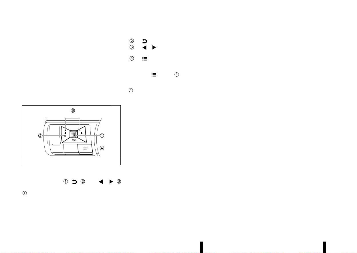
(86,1)
82 Instruments and controls
For language settings, see “[Unit/Language]” (P.89).
CHANGING THE METER SCREEN VIEW
(models with full-screen display)
MEVT33A1-9F076286-B7EA-46DF-85A0-5AECC1466B5F
For the model with full-screen display, the meter
screen view can be changed to expand the vehicle
information display area. See “Changing the meter
screen view (models with full-screen display)” (P.69)
for how to change the view.
HOW TO USE THE VEHICLE INFORMA-
TION DISPLAY
MEVT33A1-F8D0322A-B22A-4766-9C1E-40C705DBD19A
MWAC0822X
The vehicle information display can be changed
using the scroll dial
, , and
located on the steering wheel.
Scroll dial - navigate through the items and
change or select an item in vehicle informa-
tion display
this scroll dial allows up/down navigation
and push to select
- go back to the previous menu
- change from one display screen to
the next (i.e. trip, Fuel economy)
- display the [Shortcut Menu] screen
SHORTCUT MENU
MEVT33A1-249C72A3-AEBB-4CBF-87FF-7AC598DFFA1F
When the button is pushed, the [Shortcut
Menu] screen appears on the vehicle information
display. Select the menu by rotating the scroll dial
and push it.
The following menus are available:
* [Emergency Lane] (where fitted)
Allows user to turn the Emergency Lane Assist
(ELA) system ON/OFF.
* [Change Display View] (where fitted)
Allows user to change the meter screen view.
(See “Changing the meter screen view (models
with full-screen display)” (P.69).)
* [Audio Source] (where fitted)
Allows user to select the available audio
source. (See the separate NissanConnect
Owner’s Manual for the audio system.)
* [Driver Assistance] (where fitted)
Allows user to change some functions in the
[Driver Assistance] settings. (See “[Driver Assis-
tance]” (P.83).)
* [Personal Display] (where fitted)
Allows user to change the [Personal Display]
settings. (See “[Personal Display] (where fitted)”
(P.84).)
STARTUP DISPLAY
MEVT33A1-90A3D848-634B-472C-AF5E-15E3842FBF27
When the ignition switch is placed in the ON
position, the vehicle information display may dis-
play the following screens if the vehicle is equipped
with them:
* [Home]
* [Blank]
* [Speed]
* [Drive Computer]
* [Fuel Economy]
* [ECO Pedal Guide]
* [Tyre Pressures]
* [Stop/Start]
* [Variable Compression Turbo]
* [Navigation]
* [Compass]
* [Audio]
* [Driving Aids]
* [Intelligent Cruise Control] (ICC)
* [ProPILOT Assist]
* [Traffic Sign]
* [Warnings]
* [Settings]
Warnings will only appear if there are any present.
For more information on warnings and indicators,
see “Vehicle information display warnings and
indicators” (P.91).
To control what items appear in the vehicle
information display, see “[Settings]” (P.83).

(87,1)
[SETTINGS]
MEVT33A1-E233C786-3E74-4173-8958-C7A5639566C3
The setting mode allows user to change the
information displayed in the vehicle information
display and some settings:
* [VDC Setting] (except for Europe) / [ESP
Setting] (for Europe)
* [Driver Assistance]
* [Personal Display] (where fitted)
* [Head-Up Display] (where fitted)
* [ECO Settings]
* [Tyre Pressures]
* [Clock]
* [Vehicle Settings]
* [Maintenance]
* [Display Settings]
* [Unit/Language]
* [I-Key Link] (where fitted)
* [Factory Reset]
[VDC Setting]/[ESP Setting]
MEVT33A1-96070DCB-ACAE-48CC-8334-FDE687F7C9E8
To change the setting, use the scroll dial to
select and push it.
* System
Allows user to turn the Vehicle Dynamic
Control (VDC)/Electronic Stability Programme
(ESP) system ON or OFF. By default the VDC/
ESP system will be turned ON. If the VDC/ESP
system is turned off, the VDC/ESP OFF indi-
cator light will illuminate.
NOTE:
The vehicle should be driven with the VDC/ESP
system ON for most driving conditions. (See
“Vehicle Dynamic Control (VDC)/Electronic Sta-
bility Programme (ESP) system” (P.391).)
[Driver Assistance]
MEVT33A1-4BAE8C7C-F73E-403E-98F8-E2D0124F6AD9
To change the status, warnings or turn on or off
any of the systems/warnings displayed in the
[Driver Assistance] menu, use the scroll dial
to
select and change a menu item:
* [Steering Assist] (where fitted)
* [Lane] (where fitted)
* [Blind Spot] (where fitted)
* [Emergency Brake] (where fitted)
* [Traffic Sign] (where fitted)
* [CRUISE Navi Link] (where fitted)
* [Speed Limit Link] (where fitted)
* [Speed Link Offset] (where fitted)
* [Parking Aids] (where fitted)
* [Rear Cross Traffic Alert] (where fitted)
* [Driver Attention Alert] (where fitted)
* [Timer Alert]
* [Low Temp. Alert]
* [Steering Effort]
[Steering Assist] (where fitted):
Allows user to turn the Steering Assist ON/OFF.
(See “ProPILOT Assist (where fitted)” (P.329).)
[Lane] (where fitted):
* [Warning]
Allows user to turn the Lane Departure Warn-
ing (LDW) system ON/OFF.
* [Intervention]
Allows user to turn the Intelligent Lane Inter-
vention system ON/OFF.
* [Emergency Lane] (where fitted)
Allows user to turn the Emergency Lane Assist
(ELA) system ON/OFF.
* [Lane Sensitivity] (where fitted)
Allows user to select an item from below.
— [Strong]
— [Normal]
— [Mild]
* [Vibration level]
Allows user to select an item from below.
— [High]
— [Mid.]
— [Low]
(See “Lane Departure Warning (LDW) (where fitted)”
(P.274), “Intelligent Lane Intervention (where fitted)”
(P.277) and “Emergency Lane Assist (ELA) system
(where fitted)” (P.282).)
[Blind Spot] (where fitted):
* [Warning]
Allows user to turn the Blind Spot Warning
(BSW) system ON/OFF.
* [Intervention] (where fitted)
Allows user to turn the Intelligent Blind Spot
Intervention system ON/OFF.
(See “Blind Spot Warning (BSW) (where fitted)”
(P.289) and “Intelligent Blind Spot Intervention
(where fitted)” (P.295).)
Instruments and controls 83

(88,1)
84 Instruments and controls
[Emergency Brake] (where fitted):
Models without Rear Automatic Braking (RAB)
system:
Allows user to turn the Intelligent Emergency
Braking with Pedestrian Detection system and
Intelligent Forward Collision Warning system ON/
OFF.
Models with Rear Automatic Braking (RAB) system:
* [Front]
Allows user to turn the Intelligent Emergency
Braking with Pedestrian Detection system and
Intelligent Forward Collision Warning system
ON/OFF.
* [Rear]
Allows user to turn the Rear Automatic Brak-
ing (RAB) system ON/OFF.
(See “Intelligent Emergency Braking with Pedes-
trian Detection system” (P.359), “Intelligent Forward
Collision Warning” (P.369) and “Rear Automatic
Braking (RAB) (where fitted)” (P.377).)
[Traffic Sign] (where fitted):
Allows user to turn the Traffic Sign Recognition
(TSR) ON/OFF. (See “Traffic Sign Recognition (TSR)”
(P.271).)
[CRUISE Navi Link] (where fitted):
Allows user to turn the CRUISE Navi Link function
ON/OFF.
[Speed Limit Link] (where fitted):
Models without ProPILOT Assist with Navi-link:
Allows user to turn the Speed Limit Link function
ON/OFF.
Models with ProPILOT Assist with Navi-link:
Allows user to customise the Speed Limit Link
function.
* [OFF]
* [Prompt]
* [Auto]
[Speed Link Offset] (where fitted):
Allows user to set whether the speed limit used by
the Speed Limit Link function will be accepted
exactly or with some tolerance.
[Parking Aids]:
To change the status or turn on or off any of the
systems displayed in the [Parking Aids] menu, use
the scroll dial
to select and change a menu item:
* [Moving Object] (where fitted)
Allows user to turn the Moving Object Detec-
tion (MOD) ON/OFF.
* [Display]
Allows user to turn the parking sensor (sonar)
system display ON/OFF.
* [Front] (where fitted)
Allows user to turn the front sensors ON/OFF.
* [Rear]
Allows user to turn the rear sensors ON/OFF.
* [Distance]
Allows user to select the sensor’s detection
distance (Far, Medium or Near).
* [Volume]
Allows user to select the volume of the tone
(High, Medium or Low).
(See “Moving Object Detection (MOD) (where
fitted)” (P.200) and “Parking sensor (sonar) system”
(P.395).)
[Rear Cross Traffic Alert] (where fitted):
Allows user to turn the Rear Cross Traffic Alert
(RCTA) system ON/OFF. (See “Rear Cross Traffic
Alert (RCTA) (where fitted)” (P.304).)
[Driver Attention Alert] (where fitted):
Allows user to turn the Intelligent Driver Alertness
on or off. (See “Intelligent Driver Alertness (where
fitted)” (P.375).)
[Timer Alert]:
Allows user to adjust the Timer Alert or reset.
* (Current Time)/(Set Time)
* [Reset]
[Low Temp. Alert]:
Allows user to turn the Low Temperature Alert
function ON/OFF.
[Steering Effort]:
Allows user to adjust the power steering to reduce
or increase steering effort.
* [Drive Mode]
* [Standard]
* [Sport]
[Personal Display] (where fitted)
MEVT33A1-AAE638FC-42EB-4197-A94F-E4D2A5ADF88D
To change the display in the [Personal Display]
menu, use the scroll dial
to select and change a
menu item:
* [Blank]
(89,1)
* [Navigation] (where fitted)
* [Time to Destination] (where fitted)
* [Fuel Economy]
— [Since Reset]
— [Since Start]
— [Since Refuel]
* [Trip]
— [Since Reset]
— [Since Start]
— [Since Refuel]
* [Gear Position]
* [Average Speed]
— [Since Reset]
— [Since Start]
— [Since Refuel]
[Head-Up Display] (where fitted)
MEVT33A1-858B3DE8-E1C5-4BE9-BFAB-A0FA03F7AA39
To change the status or turn on or off any of the
systems displayed in the [Head-Up Display] menu,
use the scroll dial
to select and change a menu
item:
* [Brightness]
* [Height]
* [Rotation]
* [Contents Selection]
— [Navigation] (where fitted)
— [Driving Aids]
— [Traffic Sign]
— [Audio]
— [Telephone]
* [Reset]
(See “[Head Up Display (HUD)] (where fitted)”
(P.105).)
[ECO Settings]
MEVT33A1-62C1E47D-282E-46D7-9B40-8F52F1174644
This setting allows user to change the ECO mode
system settings.
To change the status or turn on or off any of the
systems displayed in the [ECO Settings] menu, use
the scroll dial
to select and change a menu item:
* [ECO Drive Mode]
— [ECO Cruise Control]
— [Stop/Start]
— [ECO Climate Control]
* [ECO Info Settings]
— [ECO Indicator]
— [ECO Drive Report]
* [View History]
To reset the View History:
1) Select [View History] using the scroll dial
and push it.
2) Push the scroll dial
.
3) Select [Yes] by pushing the scroll dial
.
* [Tyre ECO advice] (where fitted)
Push the scroll dial
to turn the [Tyre ECO
advice] ON/OFF.
[Tyre Pressures]
MEVT33A1-82A0193C-FDEF-44BE-93FE-476A5CD771E7
The settings in the [Tyre Pressures] menu are all
related to the Tyre Pressure Monitoring System
(TPMS). (See “Tyre Pressure Monitoring System
(TPMS)” (P.240) and “Tyre placard” (P.462).)
* [Target Front]
* [Target Rear]
* [Tyre Pressure Unit]
* [Calibrate]
[Target Front]:
The [Target Front] tyre pressure is the pressure
specified for the front tyres on the tyre placard.
Use the scroll dial
to select and change the
value for the [Target Front] tyre pressure.
[Target Rear]:
The [Target Rear] tyre pressure is the pressure
specified for the rear tyres on the tyre placard.
Use the scroll dial
to select and change the
value for the [Target Rear] tyre pressure.
Instruments and controls 85
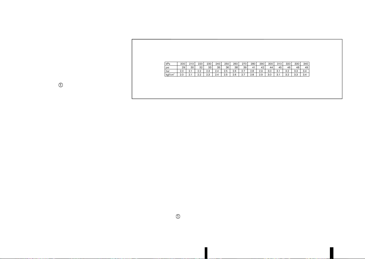
(90,1)
86 Instruments and controls
[Tyre Pressure Unit]:
The unit for tyre pressure that is shown in the
vehicle information display can be changed to:
* [psi]
* [bar]
* [kPa]
* [kgf/cm
2
]
Use the scroll dial
to select and change the unit.
If necessary, refer to the following table to convert
between units.
MJVI0938X
When the tyre pressure unit is changed, the unit for
the turbo charger boost pressure gauge is also
changed. (See “Variable Compression Turbo”
(P.72).)
[Calibrate]:
The tyre pressure is affected by the temperature of
the tyre; the tyre temperature increases when the
car is driven. To be able to accurately monitor the
tyre air leakage and to prevent false TPMS warn-
ings due to changes in temperature, the TPMS
system uses temperature sensors in the tyres to
perform temperature compensation calculations.
On rare occasions it may be necessary to recali-
brate the TPMS system reference temperature.
This operation should only be performed when the
actual tyre pressure has been adjusted, while the
current ambient temperature is significantly dif-
ferent to the current calibration temperature. (See
“Tyre Pressure Monitoring System (TPMS)” (P.240).)
Use the scroll dial
to start or cancel the
calibration process. (See “TPMS resetting” (P.242).)
[Clock]
MEVT33A1-8F1CA551-D7A7-4C32-A0C6-E40F2801FF12
Allows user to adjust the clock settings and time
within the vehicle information display.
* [Display]
* [Clock Mode] (where fitted)
* [Clock Format]
* [Summer Time] (where fitted)
* [Time Zone] (where fitted)
* [Set Clock Manually] (where fitted)
The clock may also be set in the centre display. See
“Audio main operation” (P.218) (where fitted) or the
separate NissanConnect Owner’s Manual.
[Vehicle Settings]
MEVT33A1-3672DC67-1462-4A3A-A242-4C0FA84E3384
The vehicle settings allows user to change settings
for the following menus.
* [Power Back Door] (where fitted)
* [Lighting]
* [Turn indicator]

(91,1)
* [Locking]
* [Wipers]
* [Alarm System] (where fitted)
* [Driving Position] (where fitted)
* [Rear Door Alert] (where fitted)
* [Mirror Fold]
The vehicle settings can be changed using the
scroll dial
.
[Power Back Door] (where fitted):
This allows user to turn the power back door ON or
OFF.
[Lighting]:
The [Lighting] menu has the following options:
* [Welcome Light]
The welcome lighting can be set to be ON or
OFF. Use the scroll dial
to turn this feature
ON or OFF.
* [Auto Room Lamp]
The interior light can be set to be ON or OFF.
Use the scroll dial
to turn this feature ON or
OFF.
* [Mood Lighting] (where fitted)
The brightness of the Mood Lighting can be
adjusted. Use the scroll dial
to select the
brightness.
[Turn indicator] (where fitted):
The [3 Flash On] overtaking feature can be set to
be ON or OFF. From the [Turn indicator] menu,
select [3 Flash On]. Use the scroll dial
to turn this
feature ON or OFF.
[Locking]:
The [Locking] menu has the following options:
* [I-Key Door Lock] (where fitted)
When this item is turned on, the lock or
capacitive unlock sensors (on the front door
handles) and the request switch are activated.
Use the scroll dial
to activate or deactivate
this function.
* [Selective Unlock]
When this item is turned on, only the corre-
sponding door is unlocked when using the
capacitive unlock sensor on the door handles
or the request switch (where fitted). All the
doors can be unlocked if the lock sensor is
touched within 5 seconds after using the
capacitive unlock sensor or the request switch
is pushed again within 5 seconds after push-
ing the request switch. When this item is
turned to off, all the doors will be unlocked
when using the capacitive unlock sensor or
the request switch once. Use the scroll dial
to activate or deactivate this function.
[Wipers]:
The [Wipers] menu has the following options:
* [Speed Dependent]
The [Speed Dependent] feature can be acti-
vated or deactivated. Use the scroll dial
to
turn this feature ON or OFF.
* [Auto Wipe]
The [Auto Wipe] feature can be activated or
deactivated. Use the scroll dial
to turn this
feature ON or OFF.
* [Reverse Link]
The [Reverse Link] wiper feature can be set to
be ON or OFF. Use the scroll dial
to turn this
feature ON or OFF.
[Alarm System] (where fitted):
The [Alarm System] menu has the following
options:
* [Always ON]
When this item is selected, the ultrasonic
sensor will activate each time the alarm is set.
* [Ask on Exit]
When this item is selected, the alarm system
will provide the choice to disable the interior
movement sensors after the ignition switch is
placed in the "OFF" position.
* [Disable Once]
When this item is selected, the ultrasonic
sensor will be disabled until the next time the
alarm system is disarmed.
[Driving Position] (where fitted):
* [Exit Seat Slide]
Allows user to turn this feature ON or OFF. (See
“Automatic drive positioner (where fitted)”
(P.169).)
[Rear Door Alert] (where fitted):
Allows user to select an item below.
* [Horn & Alert]
* [Alert Only]
* [OFF]
Instruments and controls 87
(92,1)
88 Instruments and controls
[Mirror Fold]:
Allows user to select an item below.
* [Auto Fold Off]
* [Unfold at Ignition]
* [Unfold at Unlock]
[Maintenance]
MEVT33A1-C4CD29BE-A25A-4D00-A0C8-876E59C65704
The maintenance mode allows user to check the
distance to oil change or set alerts for the
reminding of maintenance intervals. To change
an item:
Select [Maintenance] using the scroll dial
and
push it.
* [Service]
* [Air Filter]
* [Tyre]
* [Other]
[Service]:
The Service (Oil Control System) informs the
distance to oil change. Never exceed one year or
15,000 km (9,000 miles) between oil change
intervals.
Display
when
ignition is
ON
Display timing
Action Required
Engine Oil
Service
due in xxx
km (miles)
Remaining oil life is
less than 1,500 km
(940 miles), 1,000
km (625 miles), 500
km (312.5 miles),
400 km (250
miles), 300 km
(187.5 miles), 200
km (125 miles), 100
km (62.5 miles).
Plan to have your
vehicle serviced.
Engine Oil
Service
due
Remaining oil life is
0 km (0 miles).
Have your vehicle
serviced within two
weeks or less than
800 km (500
miles).
The oil change interval cannot be adjusted manu-
ally.
The distance to oil change interval is calculated
depending on the driving conditions and set
automatically by the oil control system. A reminder
will be displayed when approaching the end of the
service interval.
When the [Factory Reset] option is selected in the
vehicle information display, the oil control system
will also be reset to initial value. Please change the
engine oil when [Factory Reset] is selected.
CAUTION
If the oil replacement indicator is displayed,
change the engine oil within two weeks or less
than 800 km (500 miles).
Operating the vehicle with deteriorated oil can
damage the engine.
To reset oil control system:
1. Place the ignition switch in the ON position.
2. Push the
and buttons on the steering
wheel until [Settings] appears in the vehicle
information display. Use the scroll dial
to
select [Maintenance]. Then, push the scroll dial
.
3. Select the [Service] and push the scroll dial
.
4. Push the scroll dial
according to the reset
instructions displayed at the bottom of the
[Service] maintenance screen.
When the user sets an alert for changing the
engine oil in an other menu, reset both [Service]
and the menu after changing the engine oil.
[Air Filter]:
This indicator appears when user set distance
comes for changing the air filter. You can set or
reset the distance for checking or replacing these
items. For scheduled maintenance items and
intervals, see a separate maintenance booklet.
[Tyre]:
This indicator appears when the user set distance
comes for replacing tyres. You can set or reset the
distance for replacing tyres.
WARNING
The tyre replacement indicator is not a sub-
stitute for regular tyre checks, including tyre
pressure checks. (See “Changing tyres and
wheels” (P.450).) Many factors including tyre
inflation, alignment, driving habits and road
conditions affect tyre wear and when tyres
should be replaced. Setting the tyre replace-

(93,1)
ment indicator for a certain driving distance
does not mean your tyres will last that long.
Use the tyre replacement indicator as a guide
only and always perform regular tyre checks.
Failure to perform regular tyre checks, includ-
ing tyre pressure checks could result in tyre
failure. Serious vehicle damage could occur
and may lead to a collision, which could result
in serious personal injury or death.
[Other]:
This indicator appears when the user set distance
comes for checking or replacing maintenance
items other than the engine oil, air filter and tyres.
Other maintenance items can include such a thing
as tyre rotation. You can set or reset the distance
for checking or replacing the items.
[Display Settings]
MEVT33A1-F20D3FC2-CB7C-4785-AF30-9F40E9B4FFC3
The display settings allows user to choose from
the various meter selections.
The display settings can be changed using the
scroll dial
.
Contents Selection:
Displays available screens that can be shown in
the vehicle information display.
Route Guidance (where fitted):
To change the setting, use the scroll dial
to
select and push it.
* [Alert(s)]
The [Alert(s)] allows user to turn the Navigation
Settings alerts on or off.
[AUTO Cruise Display] (where fitted):
The [AUTO Cruise Display] allows user to turn the
cruise screen transition on or off.
[Welcome Effect]:
The [Welcome Effect] displays the available wel-
come effect setting.
* [Gauges] (where fitted)
* [Animation]
Operation Guidance:
The [Operation Guidance] displays the available
operation guidance settings.
* [Lights]
* [Wiper]
— [Front]
— [Rear]
* [High beam assist] (where fitted)
* [Adaptive Headlight] (where fitted)
* [Seat Memory] (where fitted)
* [Speed limiter] (where fitted)
* [Cruise Control] (where fitted)
[Unit/Language]
MEVT33A1-39CD3CB2-7EC3-477A-B1A8-B21D4F076815
The units or language that are shown in the
vehicle information display can be changed:
* [Distance/Fuel]
* [Tyre Pressures]
* [Temperature]
* [Language]
Use the scroll dial
to select and change the units
of the vehicle information display.
[Distance/Fuel]:
The unit for the mileage that is shown in the
vehicle information display can be changed.
* [miles, MPG] (where fitted)
* [km, l/100km]
* [km, km/l]
* [miles, MPG(UK)] (where fitted)
* [miles, MPG(US)] (where fitted)
Use the scroll dial
to select and change the unit.
[Tyre Pressures]:
The unit for tyre pressures that is shown in the
vehicle information display can be changed to:
* [psi]
* [bar]
* [kPa]
* [kgf/cm
2
]
(See “[Tyre Pressures]” (P.85).)
When the tyre pressure unit is changed, the unit for
the turbo charger boost pressure gauge is also
changed. (See “Variable Compression Turbo”
(P.72).)
[Temperature]:
The temperature that is shown in the vehicle
information display can be changed from:
* [°C]
* [°F]
Use the scroll dial
to toggle choices.
[Language]:
The language of the vehicle information display
can be changed.
Instruments and controls 89

(94,1)
90 Instruments and controls
Use the scroll dial to select and change the
language of the vehicle information display.
[I-Key Link] (where fitted)
MEVT33A1-079C8A88-134F-403F-AA99-7E3CA67FA5BD
The I-Key Link can be turned ON/OFF using the
scroll dial
. It will display the key synchronized
and in use for this vehicle.
[Factory Reset]
MEVT33A1-B12D8C53-7B17-459E-B18A-0A7D125A54F1
The settings in the vehicle information display can
be reset back to the factory default. To reset the
vehicle information display:
1. Select [Factory Reset] using the scroll dial
and push it.
2. Select [Yes] to return all settings back to
default by pushing the scroll dial
.
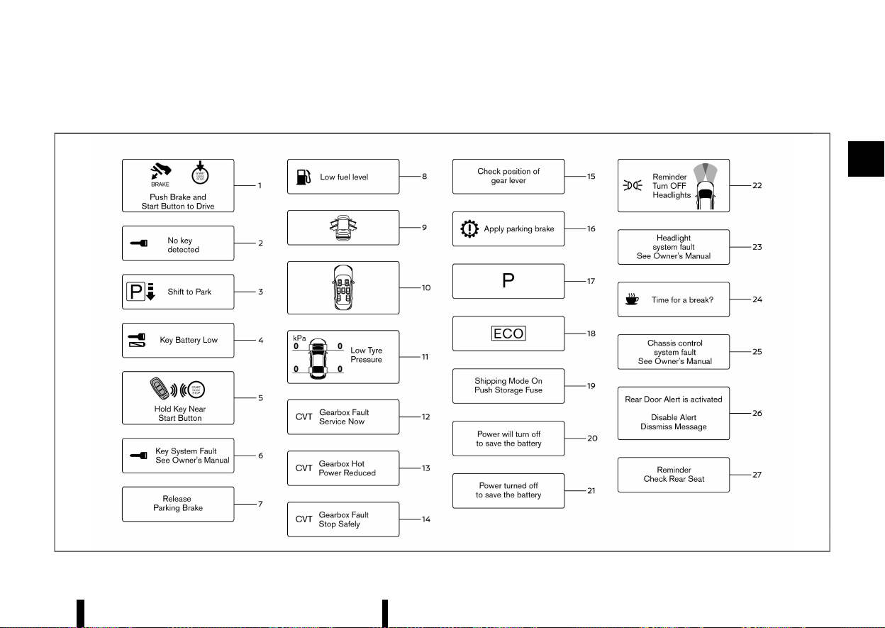
(95,1)
VEHICLE INFORMATION DISPLAY WARNINGS AND INDICATORS
MEVT33A1-CA7D0C05-2E4C-40FB-9EFB-185514B7E532
MWAC0945X
Instruments and controls 91
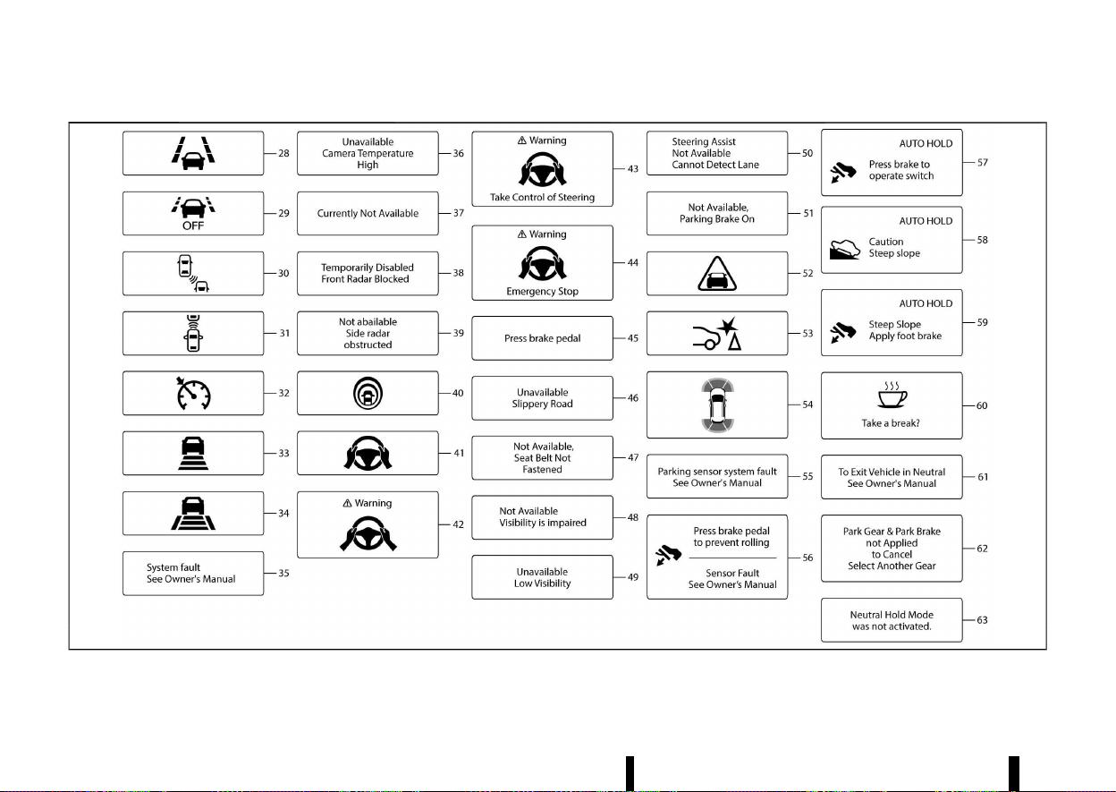
(96,1)
92 Instruments and controls
MWAC0946XV2
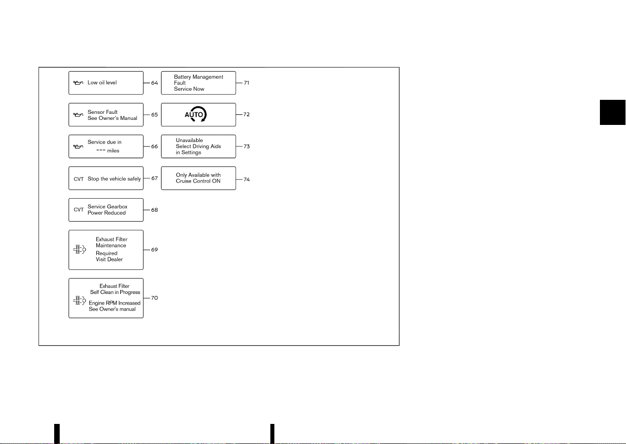
(97,1)
MWAC0947X
The displayed images may differ depending on the
model.
1. [Push Brake and Start Button to Drive] indicator
MEVT33A1-0D73D198-9373-456B-BC09-DCA7D1B28AA7
This indicator appears when the shift position is in
the P (Park) position.
This indicator means that the engine will start by
pushing the ignition switch with the brake pedal
depressed. You can start the engine directly in any
position of the ignition switch.
2. [No key detected] warning
MEVT33A1-A8E495E1-3BB6-4137-9793-4ED36995E1AE
This warning appears when the door is closed with
the Intelligent Key left outside the vehicle and the
engine is running. Make sure that the Intelligent
Key is inside the vehicle.
See “Intelligent Key system” (P.146) for more details.
3. [Shift to Park] warning (where fitted)
MEVT33A1-D16926C4-A757-422F-82CA-EC0415BC36A2
This warning appears when the door is opened
while the shift position is other than P (Park).
If this warning appears, push the park button to
engage the P (Park) position.
An inside warning chime will also sound. (See
“Intelligent Key system” (P.146).)
4. [Key Battery Low] warning
MEVT33A1-9DBCCBD2-E0A3-41CA-882F-B0A9F2668A9F
This warning appears when the Intelligent Key
battery is running out of power.
If this indicator appears, replace the battery with a
new one. See “Intelligent Key battery” (P.439).
Instruments and controls 93

(98,1)
94 Instruments and controls
5. [Hold Key Near Start Button] indicator
MEVT33A1-28B9DEE1-5616-442D-BFAA-07799C87BAAC
This indicator appears when the Intelligent Key
battery is running out of power and when the
Intelligent Key system and vehicle are not com-
municating normally.
If this indicator appears, touch the ignition switch
with the Intelligent Key while depressing the brake
pedal. (See “Intelligent Key battery discharge”
(P.246).)
6. [Key System Fault See Owner’s Manual] warning
MEVT33A1-2FA0B297-40CF-4C7C-91DF-7A1FFFF76AEC
This warning appears if there is a malfunction in
the Intelligent Key system.
If this warning appears while the engine is
stopped, the engine cannot be started. If this
warning appears while the engine is running, the
vehicle can be driven. However, it is recommended
that you visit a NISSAN dealer or qualified work-
shop for repair as soon as possible.
7. [Release Parking Brake] warning
MEVT33A1-06AD7F99-6D58-4B3F-9BFD-B383D31FCE28
This warning appears when the accelerator pedal
is depressed when the electronic parking brake
automatic release function cannot be used. Re-
lease the electronic parking brake manually.
8. [Low fuel level] warning
MEVT33A1-D1E2AB22-8C58-47D3-950F-0B0ACC5CE0F6
This warning appears when the fuel level in the
fuel tank is getting low. Refuel as soon as it is
convenient, preferably before the fuel gauge
reaches 0 (Empty). There will be a small reserve
of fuel in the tank when the fuel gauge needle
reaches 0 (Empty).
9. Door/back door open warning
MEVT33A1-41D2C188-83A9-4E12-AD35-9EC6F0E720A4
This warning appears if any of the doors and/or
the back door are open or not closed securely. The
vehicle icon indicates which door or the back door
is open on the display.
10. Seat belt warning
MEVT33A1-D70FB3FA-7C7A-48A1-904F-DEAE1C096D2A
This warning appears after the ignition switch is
placed in the ON position, until the seat belt is
fastened.
For the driver’s seat, if the buckle is fastened, the
corresponding graphic will appear green. If the
buckle is not fastened, the corresponding graphic
will appear red. For front passenger’s and rear
seats, if there is no occupant on the seat, the
corresponding seat belt graphic will appear grey.
When one of the seats has been seated with
passenger, if the buckle is fastened, the corre-
sponding seat belt graphic will appear green. If the
buckle is not fastened or is changed from buckled
to unbuckled, the corresponding seat belt graphic
will appear red. If this occurs while the vehicle
speed exceeds 15 km/h (10 MPH), a buzzer will
sound. When certain objects are placed on the
front passenger’s seat and/or rear seats, they may
cause the warning to turn on.
For precautions on seat belt usage, see “Seat belts”
(P.28).
11. [Low Tyre Pressure] warning
MEVT33A1-06BEE7F2-1217-4662-A4BA-9DB172D80DD6
This warning appears when the low tyre pressure
warning light in the meter illuminates and low tyre
pressure is detected. The warning appears each
time the ignition switch is placed in the ON
position as long as the low tyre pressure warning
light remains illuminated. If this warning appears,
stop the vehicle and adjust the pressure to the
recommended COLD tyre pressure shown on the
tyre placard. (See “Low tyre pressure warning light”
(P.77) and “Tyre Pressure Monitoring System
(TPMS)” (P.240).)
12. [Gearbox Fault Service Now] warning
MEVT33A1-545835F6-755A-4501-8F28-FF84F50F9A49
This warning appears when there is a malfunction
with the CVT system. If this warning appears, have
the system checked. It is recommended that you
visit a NISSAN dealer or qualified workshop for this
service.
13. [Gearbox Hot Power Reduced] warning
MEVT33A1-2F0B283C-9C1E-47A5-815C-55C24559FB75
The CVT has a high fluid temperature protection
mode. If the fluid temperature becomes too high
(for example, climbing steep grades in high tem-
peratures with heavy loads), engine power and,
under some conditions, vehicle speed will be
decreased automatically to reduce the chance of
transmission damage. Vehicle speed can be con-
trolled with the accelerator pedal, but the engine
and vehicle speed may be reduced.
14. [Gearbox Fault Stop Safely] warning
MEVT33A1-845A6FC4-29D0-41E4-A497-3F27DE6740DC
This warning appears when there is a malfunction
with the CVT system. If this warning appears, stop
the vehicle in a safe place. Have the system
checked. It is recommended you visit a NISSAN
dealer or qualified workshop for this service.

(99,1)
15. [Check position of gear lever] warning
MEVT33A1-E4D81E54-517B-4B17-9A4D-C9DF6C1F8BC9
This warning appears if the system cannot detect
the shift position. Make sure the vehicle is placed in
a position properly. Have the system checked. It is
recommended you contact a NISSAN dealer or
qualified workshop for this service.
16. [Apply parking brake] warning
MEVT33A1-20DB20C2-1DD0-49F7-9742-15DC79DD6405
This warning appears if a malfunction occurs in
the electric shift control system. Contact a NISSAN
dealer or qualified workshop as soon as possible.
When parking the vehicle, make sure that the
parking brake is applied. If the parking brake is not
applied, the ignition switch may not be turned off.
17. Continuously Variable Transmission
(CVT) POSITION INDICATOR
MEVT33A1-51DBD7B3-A596-461A-BC5B-F733D9DC9B5F
This indicator shows the CVT shift position.
In the manual shift mode, when the transmission
does not shift to the selected gear due to a
transmission protection mode, the CVT position
indicator will blink and a chime will sound.
See “Continuously Variable Transmission (CVT)”
(P.250) for further details.
18. Drive Mode Selector indicator
MEVT33A1-637F9EC0-C23E-4F81-BDC2-9F7EB0329EEF
When a driving mode is selected using the Drive
Mode Selector, the selected mode indicator is
displayed.
* [SPORT]
* [STANDARD]
* [ECO]
(See “Drive Mode Selector” (P.248).)
19. [Shipping Mode On Push Storage
Fuse] warning (where fitted)
MEVT33A1-F81A2702-EE27-4658-923D-E54153C21737
This warning may appear if the extended storage
switch is not pushed in. When this warning
appears, push in the extended storage switch to
turn off the warning. (See “Extended storage
switch (where fitted)” (P.443).)
20. [Power will turn off to save the battery] warning
MEVT33A1-313F3D56-B01E-4E59-89E3-48AF58BF9B11
Under the specific conditions, this warning may
appear after the ignition switch is in the ON
position for a certain period of time.
21. [Power turned off to save the battery] warning
MEVT33A1-29EF4A19-807B-4B27-9E20-F7B5506933F2
Under the specific conditions, this warning may
appear after the ignition switch is automatically
turned “OFF” to save the battery.
22. [Reminder Turn OFF Headlights] warning
MEVT33A1-A324E152-FEBA-47A3-9A2A-A94658E8BA99
This warning appears when the driver side door is
opened with the headlight switch is left ON and
the ignition switch is placed in the “OFF” position.
Place the headlight switch in the “AUTO” position.
For additional information, (See “Headlight and
turn signal switch” (P.108).)
23. [Headlight system fault See Owner’s Manual] warning
MEVT33A1-A34B1E87-18EF-4A73-89E9-5A81184809D0
This warning appears if the LED headlights are
malfunctioning. Have the system checked. It is
recommended that you visit a NISSAN dealer or
qualified workshop for this service.
24. [Time for a break?] indicator
MEVT33A1-DE3CB92D-E3ED-4CD7-A646-CFC9FCCA8DED
This indicator appears when the set Timer Alert
activates. You can set the time for up to 6 hours.
25. [Chassis control system fault See
Owner’s Manual] warning
MEVT33A1-2C4A0C79-9CAE-4F9D-B77F-266F4117A5ED
This warning appears if the chassis control module
detects a malfunction in the chassis control
system. Have the system checked. It is recom-
mended that you visit a NISSAN dealer or qualified
workshop for this service. (See “Chassis control”
(P.393).)
26. [Rear Door Alert is activated indicator] (where fitted)
MEVT33A1-32C869FC-BEA9-45D5-B565-563F29C621BC
When the system is enabled, this message appears
when the Rear Door Alert system is active and can
remind the driver to check the rear seat.
* Using the steering switch, the driver can select
[Dismiss Message] to clear the display for a
period of time.
* Using the steering switch, the driver can select
[Disable Alert] to disable the horn alert and the
message for the remainder of the current trip.
For additional information, see “Rear Door Alert
(where fitted)” (P.121).
WARNING
Selecting [Dismiss Message] during a stop
within a trip temporarily dismisses the mes-
sage for that stop without turning the system
off. Alerts can be provided for other stops
during the trip. Selecting [Disable Alert] turns
off the Rear Door Alert system for the remain-
Instruments and controls 95

(100,1)
96 Instruments and controls
der of a trip and no audible alert will be
provided.
NOTE:
This system is disabled until the driver enables it
using the settings menu. See “[Vehicle Settings]”
(P.86).
27. [Reminder Check Rear Seat] indicator (where fitted)
MEVT33A1-998BFE48-8367-43B6-902F-6B553F891219
When the system is enabled, this message appears
when the vehicle comes to a complete stop, the
shift position is placed from the D (Drive) to P
(Park), and the driver exits the vehicle. This
message alerts the driver, after a period of time,
to check for items in the rear seat after the audible
alert has been provided.
NOTE:
This system is disabled until the driver enables it
using the settings menu. See “[Vehicle Settings]”
(P.86).
28. Lane Departure Warning (LDW)/INTEL-
LIGENT LANE INTERVENTION/EMERGENCY
LANE ASSIST (ELA) INDICATOR (where fitted)
MEVT33A1-8A9EA83F-4015-4066-BA81-A46333989FF5
This indicator appears when the following systems
(where fitted) are engaged.
* Lane Departure Warning (LDW)
* Intelligent Lane Intervention
* Emergency Lane Assist (ELA)
(See “Lane Departure Warning (LDW) (where fitted)”
(P.274),“Intelligent Lane Intervention (where fitted)”
(P.277) or “Emergency Lane Assist (ELA) system
(where fitted)” (P.282).)
29. [Emergency Lane Assist (ELA) OFF]
INDICATOR (where fitted)
MEVT33A1-0B379C14-D1D6-4696-B23D-32BD595CC30B
This indicator appears when the Emergency Lane
Assist (ELA) system is turned off. (See “Emergency
Lane Assist (ELA) system (where fitted)” (P.282).)
30. Blind Spot Warning (BSW)/INTELLIGENT BLIND
SPOT INTERVENTION INDICATOR (where fitted)
MEVT33A1-BD61E225-6FEF-4793-9B0A-C921C0FEFEAE
This indicator appears when the Blind Spot Warn-
ing (BSW) and/or Intelligent Blind Spot Intervention
(where fitted) systems are engaged.
(See “Blind Spot Warning (BSW) (where fitted)”
(P.289) or “Intelligent Blind Spot Intervention
(where fitted)” (P.295).)
31. Vehicle ahead detection indicator (where fitted)
MEVT33A1-9422B98B-1FEE-4D70-81EC-B675F0C584C3
This indicator shows the status of the following
systems:
* Intelligent Emergency Braking with Pedestrian
Detection
* Intelligent Forward Collision Warning
(See “Intelligent Emergency Braking with Pedes-
trian Detection system” (P.359) or “Intelligent For-
ward Collision Warning” (P.369).)
32. Cruise indicator (where fitted)
MEVT33A1-3675ECAF-4159-44CF-8B20-7B9E0203D539
Models without Intelligent Cruise Control (ICC)
system:
This indicator shows the cruise control system
status. The status is shown by the colour.
(See “Cruise control (where fitted)” (P.311).)
Models with Intelligent Cruise Control (ICC)
system:
This indicator shows the conventional (fixed
speed) cruise control mode status. The status is
shown by the colour.
(See “Conventional (fixed speed) cruise control
mode” (P.326) or “Conventional (fixed speed) cruise
control mode” (P.356).)
33. Intelligent Cruise Control (ICC) SYS-
TEM STATUS INDICATOR (where fitted)
MEVT33A1-CC090A79-6553-4B9B-B459-3411F458FFEF
This indicator shows the status of the Intelligent
Cruise Control (ICC) system (without ProPILOT
Assist system). The status is shown by the colour
and shape.
(See “Intelligent Cruise Control (ICC) (where fitted)”
(P.313).)
34. Speed control status/set distance/
lane marker indicator (where fitted)
MEVT33A1-2D404846-90B1-471A-88D4-3DA7F30A7B90
This indicator shows the status of the Intelligent
Cruise Control (ICC) system and the detection of
the lane markers. The status is shown by the
colour and shape. (See “ProPILOT Assist (where
fitted)” (P.329).)
35. [System fault See Owner’s Manual]
warning (where fitted)
MEVT33A1-2EFE0245-17D1-44E4-9CB5-E72DE3A1791B
This warning appears when the following systems
(where fitted) malfunction.
* Traffic Sign Recognition (TSR)

(101,1)
* Rear Automatic Braking (RAB)
* Rear Cross Traffic Alert (RCTA)
* Intelligent Emergency Braking with Pedestrian
Detection
* Intelligent Forward Collision Warning
* Lane Departure Warning (LDW)
* Intelligent Lane Intervention
* Emergency Lane Assist (ELA)
* Blind Spot Warning (BSW)
* Intelligent Blind Spot Intervention
* Intelligent Cruise Control (ICC)
* ProPILOT Assist
* Steering Assist
* Intelligent Driver Alertness
(See “Traffic Sign Recognition (TSR)” (P.271), “Rear
Automatic Braking (RAB) (where fitted)” (P.377),
“Rear Cross Traffic Alert (RCTA) (where fitted)”
(P.304), “Intelligent Emergency Braking with Pedes-
trian Detection system” (P.359), “Intelligent Forward
Collision Warning” (P.369), “Lane Departure Warning
(LDW) (where fitted)” (P.274), “Intelligent Lane Inter-
vention (where fitted)” (P.277), “Blind Spot Warning
(BSW) (where fitted)” (P.289), “Emergency Lane
Assist (ELA) system (where fitted)” (P.282), “Intelli-
gent Blind Spot Intervention (where fitted)” (P.295),
“Intelligent Cruise Control (ICC) (where fitted)”
(P.313), “ProPILOT Assist (where fitted)” (P.329),
“Intelligent Cruise Control (ICC)” (P.339), “Steering
Assist” (P.351) or “Intelligent Driver Alertness (where
fitted)” (P.375).)
36. [Unavailable Camera Temperature
High] warning (where fitted)
MEVT33A1-4C5FE882-4E4F-4E8D-9678-DB2B8817F20D
This warning appears if the interior temperature of
the vehicle has reached such a high temperature
that the sensor for the following systems (where
fitted) can no longer function reliably.
* Lane Departure Warning (LDW)
* Intelligent Lane Intervention
* Intelligent Blind Spot Intervention
* Steering Assist
Once the interior temperature has reached normal
levels, the warning should disappear.
If the warning continues to display, have the
system checked. It is recommended that you visit
a NISSAN dealer or qualified workshop for this
service.
For additional information, refer to “Lane Depar-
ture Warning (LDW) (where fitted)” (P.274), “Intelli-
gent Lane Intervention (where fitted)” (P.277),
“Intelligent Blind Spot Intervention (where fitted)”
(P.295) or “Steering Assist” (P.351).
37. [Currently Not Available] warning (where fitted)
MEVT33A1-2B0801BE-A3FB-41AD-81ED-82AB16428BE1
This warning appears when the Intelligent Lane
Intervention (where fitted), the Intelligent Blind
Spot Intervention (where fitted) or the Intelligent
Cruise Control (ICC) system (where fitted) becomes
unavailable because the Vehicle Dynamic Control
(VDC)/Electronic Stability Programme (ESP) system
is turned off.
For additional information, refer to “Intelligent Lane
Intervention (where fitted)” (P.277), “Intelligent Blind
Spot Intervention (where fitted)” (P.295), “Intelligent
Cruise Control (ICC) (where fitted)” (P.313), or
“Intelligent Cruise Control (ICC)” (P.339).
38. [Temporarily Disabled Front Radar
Blocked] warning (where fitted)
MEVT33A1-CAADB6C8-4EF4-40C1-B6FD-42FBF9C08AA2
If the front radar sensor area on the front of the
vehicle is covered with dirt or obstructed, making it
impossible to detect a vehicle ahead, the following
systems (where fitted) automatically turned off.
* Emergency Lane Assist (ELA) system
* Intelligent Cruise Control (ICC)
* ProPILOT Assist
* Intelligent Emergency Braking with Pedestrian
Detection
* Intelligent Forward Collision Warning
If the warning message appears, park the vehicle
in a safe location and turn the engine off.
Check to see if the sensor area is blocked. If the
sensor area is blocked, remove the blocking
material. Restart the engine. If the warning mes-
sage continues to appear, have the system
checked. It is recommended that you visit a
NISSAN dealer or qualified workshop for this
service.
For more details, see “Emergency Lane Assist (ELA)
system (where fitted)” (P.282), “Intelligent Cruise
Control (ICC) (where fitted)” (P.313), “ProPILOT Assist
(where fitted)” (P.329), “Intelligent Emergency Brak-
ing with Pedestrian Detection system” (P.359) or
“Intelligent Forward Collision Warning” (P.369).
Instruments and controls 97

(102,1)
98 Instruments and controls
39. [Not available Side radar ob-
structed] warning (where fitted)
MEVT33A1-EF197E75-B2C3-4F66-A0A2-4123D7A6028C
This warning appears when the following systems
(where fitted) become unavailable because a radar
blockage is detected.
* Emergency Lane Assist (ELA) system
* Blind Spot Warning (BSW)
* Intelligent Blind Spot Intervention
* Rear Cross Traffic Alert (RCTA)
(See “Emergency Lane Assist (ELA) system (where
fitted)” (P.282), “Blind Spot Warning (BSW) (where
fitted)” (P.289), “Intelligent Blind Spot Intervention
(where fitted)” (P.295) or “Rear Cross Traffic Alert
(RCTA) (where fitted)” (P.304).)
40. Intelligent Lane Intervention ON/Intelli-
gent Blind Spot Intervention ON/ProPILOT
Assist system status indicator (where fitted)
MEVT33A1-2552F4E6-43B4-4656-A468-EC9193C05C2E
This indicator appears when the following systems
(where fitted) are turned on:
* Intelligent Lane Intervention
* Intelligent Blind Spot Intervention
* ProPILOT Assist
See “Intelligent Lane Intervention (where fitted)”
(P.277), “Intelligent Blind Spot Intervention (where
fitted)” (P.295) or “ProPILOT Assist (where fitted)”
(P.329).
41. Steering Assist indicator (where fitted)
MEVT33A1-7B5E881C-B8D4-419A-9A7F-40601EA19D9D
This indicator appears when the Steering Assist
system is engaged.
See “ProPILOT Assist (where fitted)” (P.329).
42–44. Hands on detection warning (where fitted)
MEVT33A1-47FEFB2C-5187-4E8E-8069-AEEBE403F837
This warning may appear when the Steering Assist
system is engaged and the following condition(s)
occur:
* When not holding the steering wheel
* When there is no steering wheel operation
Hold on the steering wheel immediately. When the
steering operation is detected, the warning turns
off and the Steering Assist function is automati-
cally restored. For additional information, refer to
“ProPILOT Assist (where fitted)” (P.329).
45. [Press brake pedal] indicator (where fitted)
MEVT33A1-53843ADB-5EEA-4D77-B988-6D84D5AA8F02
This message may appear when the ProPILOT
Assist system is engaged and the following condi-
tion occurs:
* While the vehicle is stopped by the ProPILOT
Assist system, the driver’s door is opened but
the electronic parking brake was not acti-
vated.
Step on the brake pedal immediately.
46. [Unavailable Slippery Road] warning (where fitted)
MEVT33A1-C156DCC3-1718-4AF2-8939-8860B29D0682
This warning appears when the following systems
(where fitted) become unavailable because the
road is slippery.
* Intelligent Lane Intervention
* Intelligent Blind Spot Intervention
* Intelligent Cruise Control (ICC)
* ProPILOT Assist
(See “Intelligent Lane Intervention (where fitted)”
(P.277), “Intelligent Blind Spot Intervention (where
fitted)” (P.295), “Intelligent Cruise Control (ICC)
(where fitted)” (P.313) or “Intelligent Cruise Control
(ICC)” (P.339).)
47. [Not Available, Seat Belt Not Fas-
tened] indicator (where fitted)
MEVT33A1-3591A0F5-16CE-4B3E-9409-A2CE367A322F
This message may appear when the ProPILOT
Assist system is engaged.
Under the following condition, the ProPILOT Assist
system is automatically cancelled:
* When the driver’s seat belt is not fastened.
The ProPILOT Assist system cannot be used when
the driver’s seat belt is not fastened.
48. [Not Available Visibility is impaired]
indicator (where fitted)
MEVT33A1-24B4051F-5518-4370-8F54-1A519A234B4E
This message may appear when the Steering
Assist system is engaged.
Under the following conditions, the Steering Assist
system is automatically cancelled:
* When the wiper (HI) operates.
* When lane markers in the travelling lane
cannot be correctly detected for a period of
time due to such items as a snow rut,
reflection of light on a rainy day or several
unclear lane markers are present.

(103,1)
If you want to use the Steering Assist system
again, cancel the ProPILOT Assist system and set it
again when lane markers are clearly visible.
49. [Unavailable Low Visibility indicator] (where fitted)
MEVT33A1-E7E1B752-A31C-4B72-9EB1-467FAEB91C08
This message may appear when the Steering
Assist system and/or Emergency Lane Assist
(ELA) is engaged.
Under the following conditions, the Steering Assist
system and/or Emergency Lane Assist (ELA) is
automatically cancelled:
* The camera area of the windscreen is fogged
up or covered with dirt, water, drops, ice, snow,
etc.
* Strong light, such as sunlight or high beams
from oncoming vehicles, enter the front cam-
era
50. [Steering Assist Not Available Can-
not Detect Lane] indicator (where fitted)
MEVT33A1-CAF4FE68-2901-4C67-83C2-A916FBF7EE58
This indicator may appear when the Steering
Assist system is engaged. The Steering Assist
system is automatically cancelled when the lane
markers in the travelling lane cannot be correctly
detected for a period of time due to such items as
a snow rut, reflection of light on a rainy day or
several unclear lane markers are present.
If you want to use the Steering Assist system
again, cancel the ProPILOT Assist system and set it
again when lane markers are clearly visible.
51. [Not Available, Parking Brake On]
indicator (where fitted)
MEVT33A1-10108F2A-7C93-4BBD-9952-9E44EFE3CF21
This message may appear when the ProPILOT
Assist system is engaged.
Under the following condition, the ProPILOT Assist
system is automatically cancelled:
* The electronic parking brake is applied.
The above system cannot be used when the
electronic parking brake is activated.
52. Intelligent Emergency Braking
emergency warning indicator
MEVT33A1-F3054CF4-3184-45B6-8AEE-3CF2B44793BB
This warning indicator appears along with an
audible warning, when the Intelligent Emergency
Braking with Pedestrian Detection system detects
the possibility of a forward collision.
See “Intelligent Emergency Braking with Pedes-
trian Detection system” (P.359).
53. Rear Automatic Braking (RAB) SYS-
TEM WARNING INDICATOR (where fitted)
MEVT33A1-C13D9964-E090-4A2C-A45A-DFCC2D385620
This warning indicator appears to indicate the
status of the Rear Automatic Braking (RAB) system.
See “Rear Automatic Braking (RAB) (where fitted)”
(P.377).
54. Parking sensor (sonar) SYSTEM IN-
DICATOR (where fitted)
MEVT33A1-84F82BD8-264A-4777-8CE7-5CD989891997
This indicator appears to indicate the status of the
parking sensor (sonar) system.
See “Parking sensor (sonar) system” (P.395).
55. [Parking sensor system fault] warning (where fitted)
MEVT33A1-86A107F8-A0BB-43A2-AF6A-A2FEF6E04BD1
This warning appears when there is a malfunction
with the parking sensor (sonar) system. (See
“Parking sensor (sonar) system” (P.395).)
56. [Press brake pedal to prevent rolling] /
[Sensor Fault See Owner’s Manual] warning
MEVT33A1-0FB14AA5-3FBD-4FAE-8D68-18A1E53D6D49
This warning appears in the following situations:
* The driver tries to release the electronic
parking brake manually without depressing
the brake pedal.
* The vehicle is stopped on a steep hill and there
is a possibility of moving backward, even if the
electronic parking brake is applied.
* This warning appears and chime sounds if the
vehicle moves while Automatic brake hold
function is activated. Apply the footbrake to
stop the vehicle moving.
57. [Press brake to operate switch] indicator
MEVT33A1-C119538B-F9CF-4422-B79D-D0AA30D34243
This indicator appears if Automatic brake hold
switch is pushed without depressing the brake
pedal while the automatic brake hold function is
activated. Depress the brake pedal and push the
switch to deactivate Automatic brake hold func-
tion. (See “Automatic brake hold” (P.173).)
58. [Caution Steep slope] indicator
MEVT33A1-C12F654F-6082-41FB-8ACF-A67F0B59261A
This indicator appears and chime sounds when
Automatic brake hold function is activated while
the vehicle is on a steep hill. Apply the footbrake to
stop the vehicle moving. (See “Automatic brake
hold” (P.173).)
Instruments and controls 99

(104,1)
100 Instruments and controls
59. [Steep Slope Apply footbrake] indicator
MEVT33A1-807A2C58-46EF-483C-B45A-979FA24E59E0
This indicator appears and chime sounds if [Cau-
tion Steep slope] indicator has appeared over
about 3 minutes. Then, the parking brake will
automatically be applied and the brake force of
the automatic brake hold will be released, and
vehicle may move or roll away unexpectedly. Apply
the footbrake to stop the vehicle moving. (See
“Automatic brake hold” (P.173).)
60. [Take a break?] indicator (where fitted)
MEVT33A1-60380D3C-B516-4F82-8B0F-F8DCF042AC04
This indicator appears when the Intelligent Driver
Alertness system detect that the driver attention is
decreasing. (See “Intelligent Driver Alertness
(where fitted)” (P.375).)
61. Neutral Hold Mode guidance indicator (where fitted)
MEVT33A1-FAE96488-39EE-4B56-9507-1ED9B38ECCFB
This indicator appears when the ignition switch is
placed in the “OFF” position while the shift position
is in the N (Neutral) position (Neutral hold mode is
available). (See “Neutral hold mode function”
(P.252).)
62. Neutral Hold Mode activated indicator (where fitted)
MEVT33A1-816F6DD5-24F5-4418-B1EE-74D27111C162
This indicator appears when the Neutral hold
mode is activated. To exit the Neutral hold mode,
place the vehicle in other than N (Neutral) position.
(See “Neutral hold mode function” (P.252).)
63. [Neutral Hold Mode was not acti-
vated] indicator (where fitted)
MEVT33A1-20BCEBDC-9D94-484D-B3CC-CD04F7220BCD
This indicator appears when the Neutral hold
mode is unavailable. To activate the Neutral hold
mode, wait for a while without shifting and then
perform the operations again. (See “Neutral hold
mode function” (P.252).)
64. [Low oil level] warning
MEVT33A1-B20AA7FC-86CA-4529-8656-E47E0CB61C62
This warning appears when the engine oil level is
low. Warm up the engine on a level surface. After at
least 10 minutes have passed since the engine was
stopped, use the engine oil dipstick to check the oil
level. (See “Engine oil” (P.430).) If the oil level is low,
add the engine oil or change the engine oil.
If the warning appears again before reaching the
oil change interval shown in a separate mainte-
nance booklet check the oil level. When the
warning appears and the oil level is low, have the
vehicle checked. It is recommended that you visit a
NISSAN dealer or qualified workshop for this
service.
NOTE:
If the vehicle is not on a level surface, accurate
measurement of the oil level may not be
possible. If [Low oil level] warning message
appears, but the level shown by the oil dipstick
is normal, move the vehicle to a level surface
and stop the engine. After at least 10 minutes
have passed, open the driver’s door and place
the ignition switch in the ON position. If the [Low
oil level] warning message appears again, add
the engine oil or change the engine oil, accord-
ing to the instructions described above.
65. [Sensor Fault See Owner’s Manual] warning
MEVT33A1-AA1FF1A0-8D8E-4762-AF9A-54C1D70D3693
This warning appears when the engine oil level
sensor may be malfunctioning. It is recommended
you contact a NISSAN dealer or qualified workshop
immediately.
66. [Engine Oil Service due in – – – km]
MEVT33A1-C9491093-9E0E-4EB0-8F19-3C02EE268B6F
This distance to oil change is displayed if the
distance to oil change is less than 100 km (62
miles).
67. [Stop the vehicle safely] warning (where fitted)
MEVT33A1-34142C4C-C100-4545-AB57-3002E9E24ECD
This warning appears when the CVT system
judges the vehicle is reversed on an uphill road
with the shift position in D (Drive), or moved
forward on a downhill road with the shift position
in R (Reverse). The engine may stall, so stop the
vehicle movement by depressing the brake pedal.
68. [Service Gearbox Power Reduced]
warning (where fitted)
MEVT33A1-F3273EE1-B734-4D0D-8643-B169C72E768E
This warning appears when the CVT power is
reduced. If this warning appears, have the system
checked. It is recommended that you visit a
NISSAN dealer or qualified workshop for this
service.
69-70. Exhaust Filter indicator (where fitted)
MEVT33A1-0C471910-1503-4462-9A6F-94C5754135AD
These messages will appear when the Petrol
Particulate Filter (GPF) becomes saturated or
clogged. Under certain driving conditions, auto-
matic regeneration of the filter may be difficult to
occur. See “Petrol Particulate Filter (PPF) (where

(105,1)
fitted)” (P.239) or contact a NISSAN dealer or
qualified workshop.
71. [Battery Management Fault Service Now] warning
MEVT33A1-84AD3B54-8B79-4616-9A68-2D8031F066DE
This warning appears when the battery system
may be malfunctioning. Have the system checked.
It is recommended that you visit a NISSAN dealer
or qualified workshop for this service.
72. [Stop/Start System] indicator
MEVT33A1-60AA7620-0A82-487E-80A8-BC98242BE2BA
This indicator shows the Stop/Start System status.
(See “Stop/Start System” (P.255).)
73. [Unavailable Select Driving Aids in
Settings] indicator (where fitted)
MEVT33A1-13338F3A-6F7E-4731-85B4-2D01D2D0FA90
This indicator appears if neither the Intelligent
Lane Intervention system nor the Intelligent Blind
Spot Intervention system is enabled on the set-
tings menu.
74. [Only Available with Cruise Control
ON] indicator (where fitted)
MEVT33A1-7C2A6A7C-177C-498E-8165-131FF90A9216
This indicator appears when the Steering Assist
switch is pushed while the Intelligent Cruise
Control (ICC) system is not turned on. (See
“ProPILOT Assist (where fitted)” (P.329).)
TRIP COMPUTER
MEVT33A1-E2015E9D-D3F4-4EF3-AE80-101D529BD40E
Instruments and controls 101
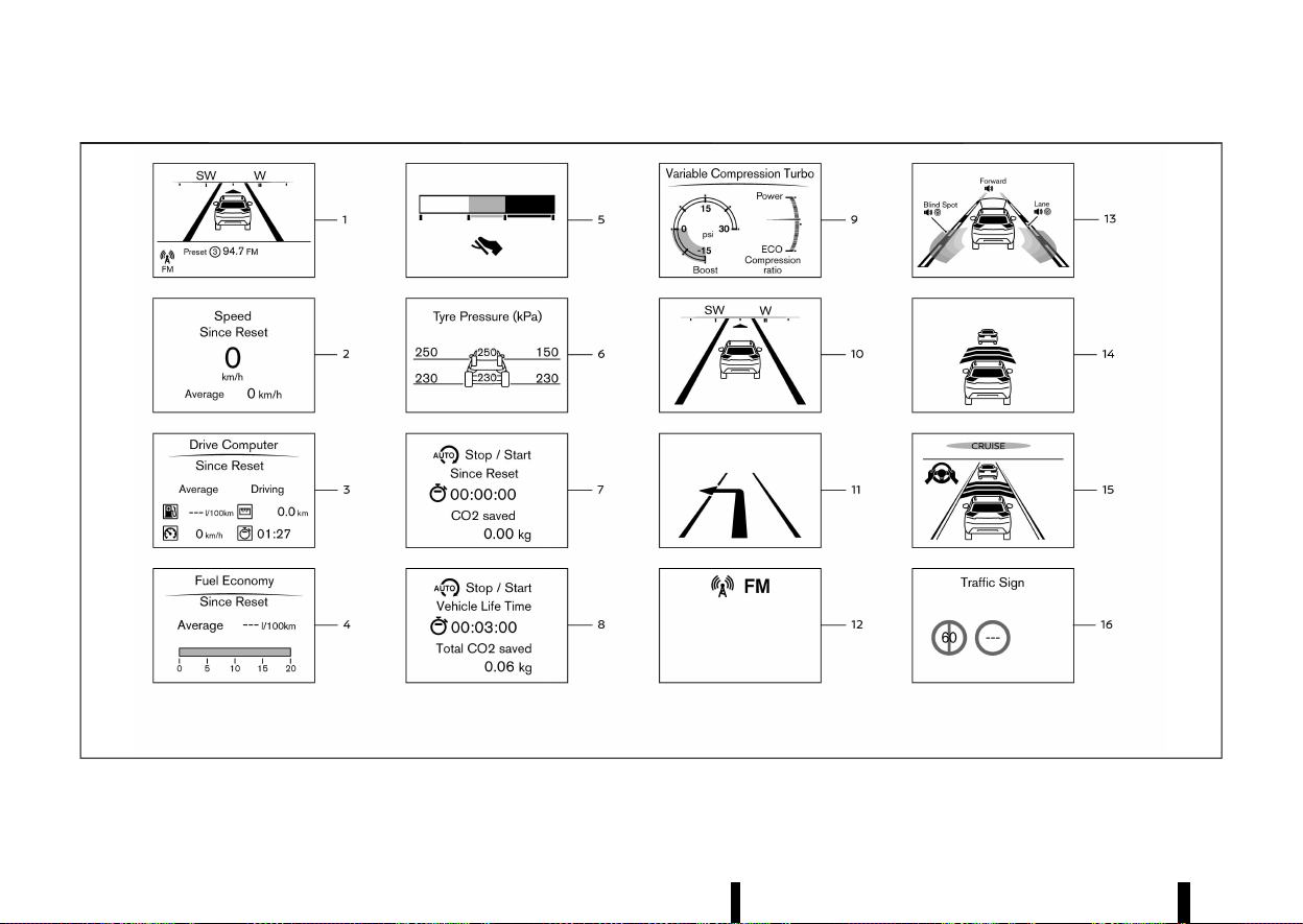
(106,1)
102 Instruments and controls
MWAC0948X
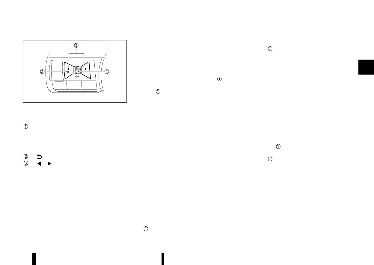
(107,1)
MWAC0313X
Switches for the trip computer are located on the
left side of the steering wheel.
Scroll dial - navigate through the items and
change or select an item in vehicle informa-
tion display
this scroll dial allows up/down navigation
and push to select
- go back to the previous menu
- change from one display screen to
the next (i.e. trip, Fuel economy)
The displayed images may differ depending on the
model.
1. Home
MEVT33A1-8CAE5A35-4F60-4FF7-8737-68DDD321D873
The Home mode shows the following information.
* Vehicle speed
* Navigation (where fitted)
* Audio
2. Speed and Average speed (where fitted)
MEVT33A1-22ED4961-284D-4D1C-8D89-C3754203E3A2
The Speed and Average speed mode shows the
current vehicle speed and the average vehicle
speed since the last reset. The Speed and Average
speed mode have three modes of operation. You
can switch between [Since Reset], [Since Start] or
[Since Refuel] by pushing the scroll dial
.
Since Reset can be reset manually by using the
scroll dial
.
Since Start will be reset automatically each time
the engine is started.
Since Refuel will be reset automatically each time
when refuelling.
3. [Drive Computer]
MEVT33A1-77390CC3-25C6-46A0-9DE6-135AEC8D94E7
Average fuel consumption:
The average fuel consumption shows the average
fuel consumption since the last reset.
Average speed:
The average speed shows the average vehicle
speed since the last reset.
Trip odometer:
The trip odometer shows the total distance the
vehicle has been driven since the last reset.
Elapsed time:
The elapsed time shows the time since the last
reset.
The Drive Computer mode have three modes of
operation. You can switch between [Since Reset],
[Since Start] or [Since Refuel] by pushing the scroll
dial
.
Since Reset can be reset manually by using the
scroll dial
.
Since Start will be reset automatically each time
the engine is started.
Since Refuel will be reset automatically each time
when refuelling.
4. Fuel Economy display
MEVT33A1-B382A276-91CF-41F7-B87C-D5A672589AFC
Current fuel consumption:
The Fuel economy display mode shows the
current fuel consumption.
Average fuel consumption:
The Fuel economy display mode shows the
average fuel consumption since the last reset.
The Fuel economy display mode have three modes
of operation. You can switch between [Since
Reset], [Since Start] or [Since Refuel] by pushing
the scroll dial
.
Since Reset can be reset manually by using the
scroll dial
.
Since Start will be reset automatically each time
the engine is started.
Since Refuel will be reset automatically each time
when refuelling.
5. ECO Pedal Guide
MEVT33A1-31846132-743B-4C8D-9AD1-C58F748E7E8D
When the ECO mode is selected, you can view the
ECO Pedal Guide function for improving fuel
economy.
The ECO Pedal Guide mode have three modes of
operation. You can switch between [Since Reset],
Instruments and controls 103

(108,1)
104 Instruments and controls
[Since Start] or [Since Refuel] by pushing the scroll
dial
.
Since Reset can be reset manually by using the
scroll dial
.
Since Start will be reset automatically each time
the engine is started.
Since Refuel will be reset automatically each time
when refuelling.
(See “ECO Pedal Guide function” (P.249).)
6. Tyre Pressure
MEVT33A1-F8135618-5ED0-44DA-A550-CE3301EF8FFF
The tyre pressure mode shows the pressure of all
four tyres while the vehicle is driven.
With the “Tyre ECO advice” function ON, when the
tyre pressure is getting low, [ECO Advice Adjust
Tyre Pressures] appears. (See “[ECO Settings]”
(P.85) and “[Tyre ECO advice] (where fitted)” (P.249).)
When the [Low Tyre Pressure] warning appears,
the display can be switched to the tyre pressure
mode by pushing the scroll dial
to reveal
additional details on the displayed warning.
7. Trip CO2 saved and engine stop time
MEVT33A1-563B5E37-43CE-45EB-9FF5-898CA25831E6
The trip CO2 saved and engine stop time (Stop/
Start System) shows the information of the Stop/
Start System.
(See “Stop/Start System” (P.255).)
8. Total CO2 saved and engine stop time
MEVT33A1-FC255862-1FFF-40C1-9D50-7A71AD38A3BF
The total CO2 saved and engine stop time (Stop/
Start System) shows the information of the Stop/
Start System.
(See “Stop/Start System” (P.255).)
9. Variable Compression Turbo
MEVT33A1-2DCBF036-8DC4-49B3-9D66-232A246544A0
Variable Compression Turbo mode shows the
status of Variable Compression Turbo information.
(See “Variable Compression Turbo” (P.72).)
10. Compass (where fitted)
MEVT33A1-DF376C40-E93E-4CBD-9285-326D17C4FAC0
This display indicates the heading direction of the
vehicle.
11. Navigation (where fitted)
MEVT33A1-418BC504-B5B5-47F5-B18F-71043322AF9F
When the route guidance is set in the navigation
system, this item shows the navigation route
information.
12. Audio
MEVT33A1-C64ACA93-070B-4BEA-9D33-8E15617DB074
The audio mode shows the status of audio
information.
13. Driver Assistance (where fitted)
MEVT33A1-A71E5616-4BCD-4B19-8AE3-30F2F0B1007E
The Driver Assistance mode shows the operating
condition for the following systems (where fitted).
* Forward:
— Intelligent Emergency Braking with Pedes-
trian Detection
— Intelligent Forward Collision Warning
* Lane:
— Lane Departure Warning (LDW)
— Intelligent Lane Intervention
* Blind Spot:
— Blind Spot Warning (BSW)
— Intelligent Blind Spot Intervention
For more details, see “Lane Departure Warning
(LDW) (where fitted)” (P.274), “Intelligent Lane Inter-
vention (where fitted)” (P.277), “Blind Spot Warning
(BSW) (where fitted)” (P.289), “Intelligent Blind Spot
Intervention (where fitted)” (P.295), “Intelligent
Emergency Braking with Pedestrian Detection
system” (P.359) or “Intelligent Forward Collision
Warning” (P.369).
14. Intelligent Cruise Control (ICC) (where fitted)
MEVT33A1-AF2374F9-604B-4C35-8466-26C09849B7A1
The Intelligent Cruise Control (ICC) mode shows
the operating condition for the ICC system.
(See “Intelligent Cruise Control (ICC) (where fitted)”
(P.313).)
15. ProPILOT Assist (where fitted)
MEVT33A1-8F87DAE4-2C00-4A8D-B3EB-231468B00F0D
The ProPILOT Assist mode shows the operating
conditions for the following systems:
* Intelligent Cruise Control (ICC)
* Steering Assist
The display will also be shown when the ProPILOT
Assist is turned on. For additional information, see
“ProPILOT Assist (where fitted)” (P.329).
16. Traffic Sign
MEVT33A1-D5DC289C-51B0-4061-9195-BB9363BCD117
The Traffic Sign Recognition (TSR) system provides
the driver with information about the most re-
cently detected speed limit. See “Traffic Sign
Recognition (TSR)” (P.271) for more details.
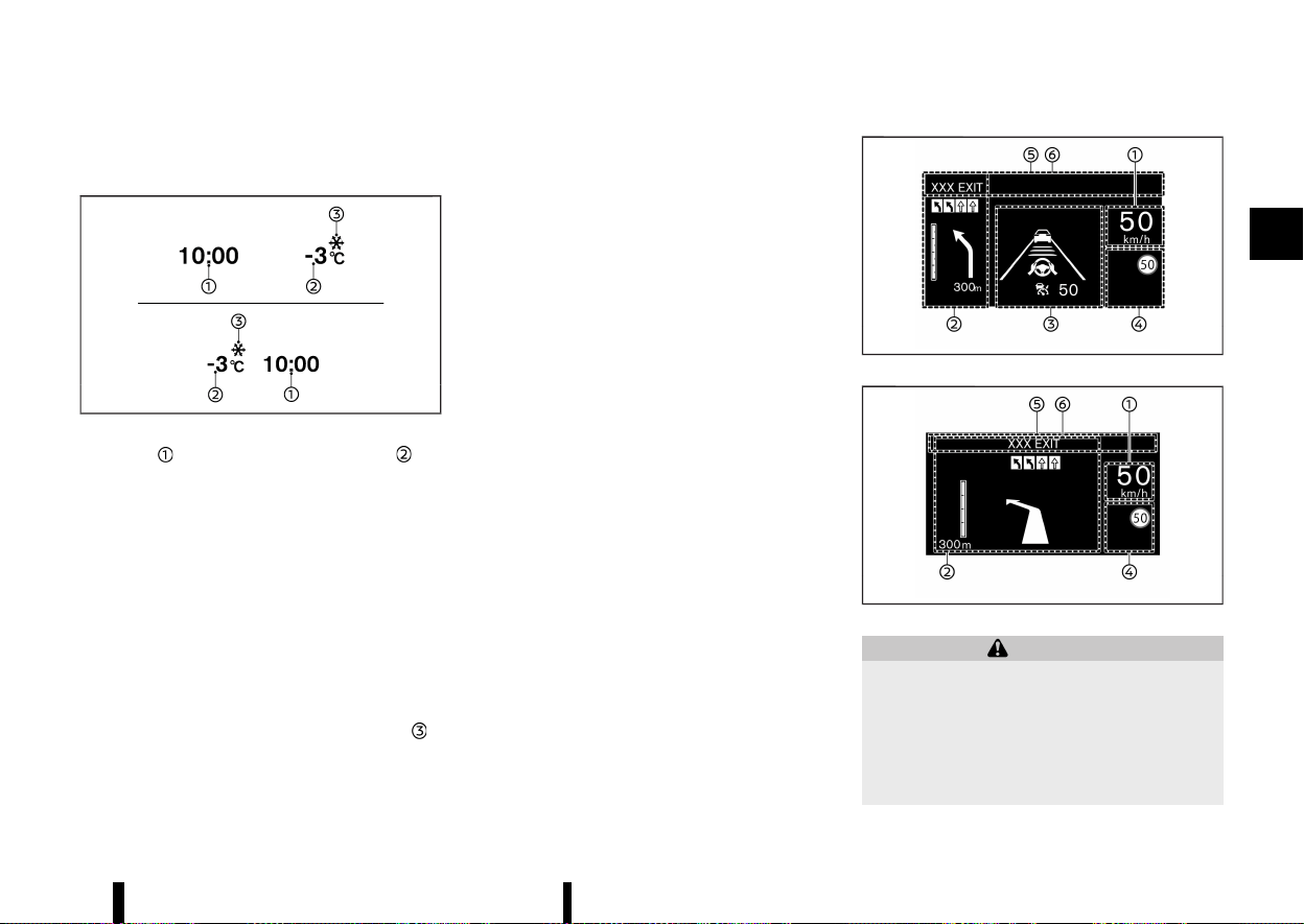
(109,1)
CLOCK AND OUTSIDE AIR TEMPERA-
TURE
MEVT33A1-0636D535-FEBB-4612-BCFD-61FB2DA5D77E
MWAC0708X
The clock and outside air temperature are
displayed on the upper side of the vehicle informa-
tion display.
Clock
MEVT33A1-FB9172E6-E0B4-427A-AE21-841F7D17FD33
For clock adjustment, see “[Clock]” (P.86) or the
separate NissanConnect Owner’s Manual (where
fitted).
Outside air temperature (°C or °F)
MEVT33A1-38E7D581-B9BE-4D16-9B8A-819340AE43CF
The outside air temperature is displayed in °C or °F
in the range of −40 to 60°C (−40 to 140°F).
The outside air temperature mode includes a low
temperature warning feature. If the outside air
temperature is below −3°C (27°F), the indicator
is
displayed.
The outside temperature sensor is located in front
of the radiator. The sensor may be affected by
road or engine heat, wind directions and other
driving conditions. The display may differ from the
actual outside temperature or the temperature
displayed on various signs, billboards or media
information.
MEVT33A1-90C008C4-AFBC-4618-9D8B-57554B157EDC
MWAC0717X
MWAC0718X
WARNING
* Failure to properly adjust the brightness
and position of the displayed image may
interfere with the driver’s ability to see
through the windscreen, which could
cause an accident leading to severe injury
or death.
* Do not use the Head Up Display (HUD) for
Instruments and controls 105
[HEAD UP DISPLAY (HUD)] (where fitted)
[HEAD UP DISPLAY (HUD)] (where fitted)
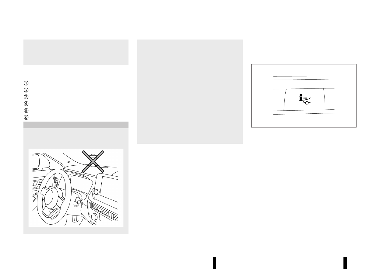
(110,1)
106 Instruments and controls
extended periods of time as that can cause
you to not see other vehicles, pedestrians
or objects, which could cause an accident
leading to severe injury or death.
The [Head Up Display (HUD)] can display one or
more of the following features (where fitted):
Vehicle speed
[Navigation]
[Driving Assist]
[Traffic Sign]
[Audio]
TEL/SMS
CAUTION
* Do not place any type of liquid on or near
the projector. Doing so may cause mal-
function of the equipment.
MWAC0515X
* Do not touch any internal parts of the
projector. Doing so may cause malfunction
of the equipment.
* To prevent scratches to the projector
glass, do not place any sharp objects on
or near the projector opening.
* Do not place any objects on the instrument
panel which may obstruct the display of
the HUD.
* For cleaning, use a soft cloth, dampened
with water. Never use a rough cloth,
alcohol, benzine, thinner or any kind of
solvent or paper towel with a chemical
cleaning agent. They will scratch or cause
discoloration to the projector lens.
* Do not spray any liquid such as water on
the projector lens. Spraying liquid may
cause the system to malfunction.
NOTE:
* If you wear polarized sunglasses, the display
may be difficult to see. Increase the bright-
ness of the HUD in the vehicle information
display or remove your sunglasses.
* Depending on weather conditions (rain,
snow, sunlight, etc.), the display may be
difficult to see.
* If the displayed image appears distorted, it
is recommended you have the system
checked by a NISSAN dealer or qualified
workshop.
* The HUD has a special windscreen to allow
the image to be displayed clearly. If your
windscreen needs replacing, this should be
performed by a NISSAN dealer or qualified
workshop.
HOW TO USE THE HUD
MEVT33A1-D17E0B9D-96BE-460E-8116-D4DF151C0B3E
MJVI1787X
To turn the HUD on, push the HUD switch. To turn
the HUD off, push the switch again.
If the HUD is turned off, it will remain off even if the
vehicle is restarted.
The following settings can be changed in the
vehicle information display:
* [Brightness]
* [Height]
* [Rotation]
* [Contents Selection]
— [Navigation] (where fitted)
— [Driving Aids]
— [Traffic Sign]
— [Audio]
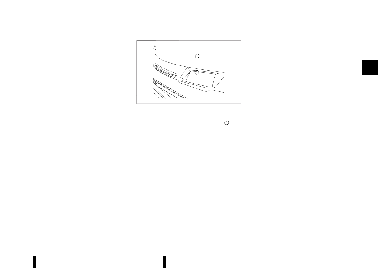
(111,1)
— [Telephone]
* [Reset]
NOTE:
Emergency information may display even if the
HUD is turned off.
This product includes the following software.
(1) Panasonic Corporation or software developed
for Panasonic Corporation
(2) Third-party software licensed to Panasonic
Corporation
(3) Open source software
Regarding (3) Open source software, it includes
open source software (OSS), including various
software to which licence information applies.
Refer to the licence web site at: http://car.pana-
sonic.jp/oss/i02lln39
Display brightness
MEVT33A1-54292B14-A82C-4832-8F53-6AD8195E108D
The brightness of the display may be controlled in
the vehicle information display. The brightness will
also be adjusted automatically according to the
exterior ambient lighting brightness.
MWAC0516X
NOTE:
* The HUD has a built-in sensor
that
controls the brightness of the displayed
image. If you block the sensor with an
object, the display will darken, making it
difficult to see.
* Do not apply strong light to the sensor of the
HUD. Doing so may cause a malfunction.
DRIVING AIDS/NAVIGATION/TRAFFIC
SIGN/AUDIO/TELEPHONE LINKING
MEVT33A1-5CE3CE2C-E2FE-4813-92ED-40EFE3B33E17
The HUD will display Driving Aids and navigation
(where fitted) information.
The Driver Assistance display will show warning
situations for the following systems (where fitted):
* Intelligent Emergency Braking with Pedestrian
Detection
* Intelligent Forward Collision Warning
* Lane Departure Warning (LDW)
* Intelligent Lane Intervention
* Emergency Lane Assist (ELA)
* Hands-free warning (for vehicles with ProPI-
LOT Assist)
The Navigation System (where fitted) linking dis-
play will show the following items:
* Intersection names
* Arrows indicating turning direction
* Distance to the next intersection
* Recommended lane indicator
The Traffic Signs Recognition (TSR) system linking
display will show the following items:
* Speed Limit Sign
* No Entry Sign
The Audio System linking display will show the
following items:
* Songs
* Radio stations
The Telephone linking display will show the
following item:
* Caller’s name or phone number
Instruments and controls 107
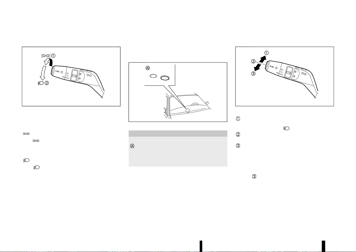
(112,1)
108 Instruments and controls
MEVT33A1-2608E54F-A0CB-4CE9-8864-9C61F01ED6F7
HEADLIGHT SWITCH
MEVT33A1-78F7386F-88AF-48CA-8EC4-39D87DBFEDF9
MWBC0123X
Example
NISSAN recommends that you consult the local
regulations concerning the use of lights.
position
MEVT33A1-C0F3013B-CF92-43DC-9A70-1B5E53135316
The position turns on the front clearance
lights, instrument panel lights, tail and number
plate lights.
position
MEVT33A1-EBF2FBA0-9CDF-4E37-9331-D6BDBD9866DC
The position turns on the headlights in
addition to the other lights.
AUTO position
MEVT33A1-CD0C7ABD-BD4A-4442-BD8D-04F1E41B1ACC
When the ignition switch is in the ON position and
the headlight switch is in the “AUTO” position, the
headlights, front clearance lights, instrument panel
lights, tail and number plate lights turn on auto-
matically depending on the brightness of the
surroundings.
The headlights will turn on automatically at twi-
light or in rainy weather (when the windscreen
wiper is operated continuously).
When the ignition switch is placed in the “OFF”
position, the lights will turn off automatically.
MWAC0522X
CAUTION
Do not place any objects on top of the sensor
. The sensor senses the brightness level and
controls the Intelligent Auto Headlight func-
tion. If the sensor is covered, it reacts as if it is
dark, and the headlights will illuminate.
The layout in the illustration is for the Left-Hand
Drive (LHD) model. For the Right-Hand Drive (RHD)
model, the sensor is located on the opposite side.
Headlight beam
MEVT33A1-65D36B20-DAE3-4840-AD10-0068CB054884
MWBC0125X
Example
To select the high beam, push the lever
forward and release it. The high beam lights
come on and the
light illuminates.
Pull the lever back and release it to select the
low beam.
To flash the headlights when the high beam
is not selected, pull the lever towards the
rear position. To flash the headlights when
the high beam is selected, pull the lever twice
towards the rear position.
When the lever is pulled towards the rearmost
position
after the ignition switch is placed in the
“OFF” position, the headlight will turn on and stay
on for 30 seconds. The lever can be pulled 4 times
for up to 2 minutes.
HEADLIGHT AND TURN SIGNAL SWITCH
HEADLIGHT AND TURN SIGNAL SWITCH
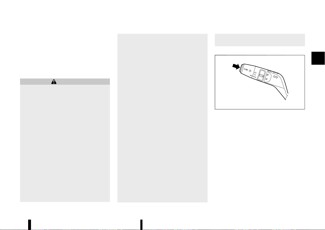
(113,1)
High beam assist (where fitted)
MEVT33A1-A3D2752C-E800-4D86-B43B-DFF9EA758B6C
The high beam assist system will operate when
the vehicle is driven at speeds of approximately 40
km/h (25 MPH) and above. If an oncoming vehicle
or leading vehicle appears in front of your vehicle
when the headlight high beam is on, the headlight
will be switched to the low beam automatically.
Precautions on high beam assist:
WARNING
* The high beam assist system is a conve-
nience but it is not a substitute for safe
driving operation. The driver should re-
main alert at all times, ensure safe driving
practices and switch the high beams and
low beam manually when necessary.
* The high beam or low beam may not
switch automatically under the following
conditions. Switch the high beam and low
beam manually.
— During bad weather (rain, fog, snow,
wind, etc.).
— When a light source similar to a head-
light or tail light is in the vicinity of the
vehicle.
— When the headlights of the oncoming
vehicle or the leading vehicle are
turned off, when the colour of the light
is affected due to foreign materials on
the lights, or when the light beam is
out of position.
— When there is a sudden, continuous
change in brightness.
— When driving on a road that passes
over rolling hills, or a road that has
level differences.
— When driving on a road with many
curves.
— When a sign or mirror-like surface is
reflecting intense light towards the
front of the vehicle.
— When the container, etc. being towed
by a leading vehicle is reflecting in-
tense light.
— When a headlight on your vehicle is
damaged or dirty.
— When the vehicle is leaning at an angle
due to a punctured tyre, being towed,
etc.
* The timing of switching the low beam and
high beam may change under the follow-
ing situations.
— The brightness of the headlights of the
oncoming vehicle or leading vehicle.
— The movement and direction of the
oncoming vehicle and the leading
vehicle.
— When only one light on the oncoming
vehicle or the leading vehicle is illumi-
nated.
— When the oncoming vehicle or the
leading vehicle is a two-wheeled vehi-
cle.
— Road conditions (incline, curve, the
road surface, etc.).
— The number of passengers and the
amount of cargo.
High beam assist operations:
MWBC0126X
Example
To activate the high beam assist system, push the
switch as illustrated with the “AUTO” position. The
high beam assist indicator light in the meter will
illuminate while the headlights are turned on.
The high beam indicator light also illuminates
when the high beam is selected by the high beam
assist system.
If the high beam assist indicator light does not
illuminate in the above condition, it may indicate
that the system is not functioning properly. It is
recommended you have the system checked by a
NISSAN dealer or qualified workshop.
When the vehicle speed lowers to less than
approximately 25 km/h (16 MPH), the headlight
remains the low beam.
Instruments and controls 109
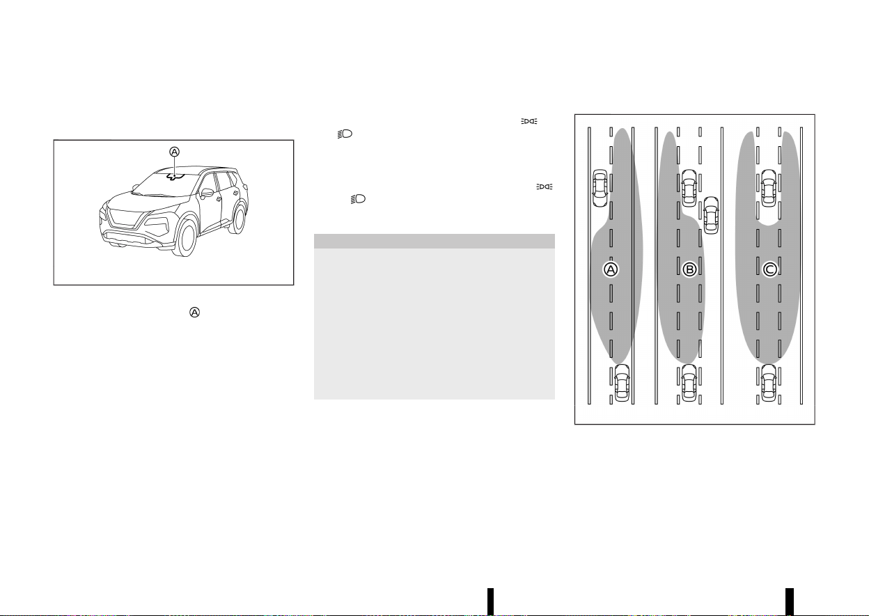
(114,1)
110 Instruments and controls
To turn off the high beam assist system, push the
switch again.
Ambient image sensor maintenance:
MWAC0523X
The ambient image sensor for the high beam
assist system is located in front of the inside
rearview mirror. To keep the proper operation of
the high beam assist system and prevent a system
malfunction, be sure to observe the following:
* Always keep the windscreen clean.
* Do not attach a sticker (including transparent
material) or install an accessory near the
ambient image sensor.
* Do not strike or damage the areas around the
ambient image sensor. Do not touch the
sensor lens that is located on the ambient
image sensor.
If the ambient image sensor is damaged due to an
accident, contact a NISSAN dealer or qualified
workshop.
Battery saver system
MEVT33A1-E8409034-D45E-48DE-A071-E3A41898289B
* When the headlight switch is in the or
position while the ignition switch is in the
ON position, the lights will automatically turn
off within a period of time after the ignition
switch has been placed in the “OFF” position.
* When the headlight switch remains in the
or position after the lights automatically
turn off, the lights will turn on when the
ignition switch is placed in the ON position.
CAUTION
* When you turn on the headlight switch
again after the lights automatically turn
off, the lights will not turn off automati-
cally. Be sure to turn the headlight switch
to the “AUTO” position when you leave the
vehicle for extended periods of time,
otherwise the battery will be discharged.
* Never leave the headlight switch on when
the engine is not running for extended
periods of time even if the headlights turn
off automatically.
Adaptive LED headlight (where fitted)
MEVT33A1-58FA8196-64F8-4961-AD56-86AD6876E852
MWBC0085X
Example
The adaptive LED headlight system will operate
when the vehicle is driven at speeds of approxi-
mately 40 km/h (25 MPH) and above. If an
oncoming vehicle or leading vehicle appears in
front of your vehicle when the headlight high
beam is on, the system will change the area
illuminated by the headlights automatically.
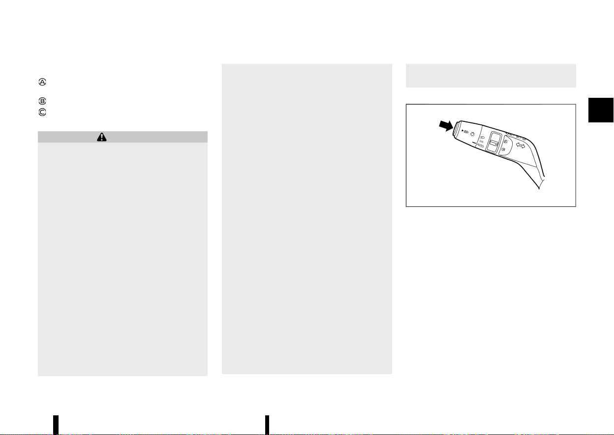
(115,1)
Example:
Right side beam only (for an oncoming
vehicle)
Left side beam only (for leading vehicles)
Split beam (for a leading vehicle)
Precautions on adaptive LED headlight:
WARNING
* The adaptive LED headlight system is a
convenience but it is not a substitute for
safe driving operation. The driver should
remain alert at all times, ensure safe
driving practices and switch the high beam
and low beam manually when necessary.
* The high beam or low beam may not
switch automatically under the following
conditions. Switch the high beam and low
beam manually.
— During bad weather (rain, fog, snow,
wind, etc.).
— When a light source similar to a head-
light or tail light is in the vicinity of the
vehicle.
— When the headlights of the oncoming
vehicle or the leading vehicle are
turned off, when the colour of the light
is affected due to foreign materials on
the lights, or when the light beam is
out of position.
— When there is a sudden, continuous
change in brightness.
— When driving on a road that passes
over rolling hills, or a road that has
level differences.
— When driving on a road with many
curves.
— When a sign or mirror-like surface is
reflecting intense light towards the
front of the vehicle.
— When the container, etc. being towed
by a leading vehicle is reflecting in-
tense light.
— When a headlight on your vehicle is
damaged or dirty.
— When the vehicle is leaning at an angle
due to a punctured tyre, being towed,
etc.
* The timing of switching the low beam and
high beam may change under the follow-
ing situations.
— The brightness of the headlights of the
oncoming vehicle or leading vehicle.
— The movement and direction of the
oncoming vehicle and the leading
vehicle.
— When only one light on the oncoming
vehicle or the leading vehicle is illumi-
nated.
— When the oncoming vehicle or the
leading vehicle is a two-wheeled vehi-
cle.
— Road conditions (incline, curve, the
road surface, etc.).
— The number of passengers and the
amount of luggage.
Adaptive LED headlight operations:
MWBC0126X
Example
To activate the adaptive LED headlight system,
push the switch as illustrated with the headlight
switch in the “AUTO” position. The adaptive LED
headlight indicator light in the meter will illuminate
while the headlights are turned on.
The high beam indicator light also illuminates
when the high beam is on.
If the adaptive LED headlight indicator light does
not illuminate in the above condition, it may
indicate that the system is not functioning prop-
erly. Have the system checked by a NISSAN dealer
or qualified workshop.
When the vehicle speed lowers to less than
approximately 25 km/h (16 MPH), the headlight
remains the low beam.
Instruments and controls 111
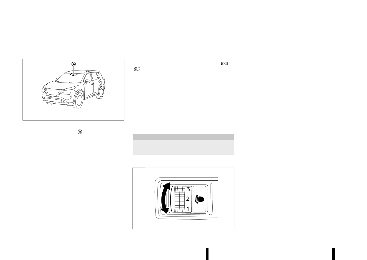
(116,1)
112 Instruments and controls
To turn off the adaptive LED headlight system,
push the switch again.
Ambient image sensor maintenance:
MWAC0523X
The ambient image sensor for the adaptive LED
headlight system is located in front of the inside
rearview mirror. To keep the proper operation of
the adaptive LED headlight system and prevent a
system malfunction, be sure to observe the
following:
* Always keep the windscreen clean.
* Do not attach a sticker (including transparent
material) or install an accessory near the
ambient image sensor.
* Do not strike or damage the areas around the
ambient image sensor. Do not touch the
sensor lens that is located on the ambient
image sensor.
If the ambient image sensor is damaged due to an
accident, contact a NISSAN dealer or qualified
workshop.
Daytime Running Light (DRL) SYSTEM
MEVT33A1-181527A2-63B6-45DF-BA28-677487A443EE
Even if the headlights are off, the daytime running
lights will come on after starting the engine.
When the headlight switch is turned to the
or
position, the daytime running light will turn
off.
HEADLIGHT CLEANER (where fitted)
MEVT33A1-B25C169D-F550-49A8-8832-F73518E72374
The headlight cleaner operates when the head-
light is on and the ignition switch is in the ON
position.
Pull the windscreen washer switch toward you.
The headlight cleaner operates with the wind-
screen washer operation. This operation activates
once each time the ignition switch is turned off
and on.
CAUTION
Add the window washer fluid reservoir when
the fluid is at a low level.
HEADLIGHT AIMING CONTROL
MEVT33A1-9927AD39-AB76-4F2B-BD19-6F23C13EFDC4
MWAC0736X
Manual type (where fitted)
MEVT33A1-E73CACDA-9543-449A-A573-9AFBB351F0E4
The headlight aiming control operates when the
ignition switch is in the ON position and the
headlight is on to allow the headlight axis to be
adjusted according to the driving condition.
When driving with no heavy load/luggage or
driving on a flat road, select the normal position
“0”.
If the number of occupants and load/luggage in
the vehicle changes, the headlight axis may
become higher than normal.
If the vehicle is travelling on a hilly road, the
headlights may directly shine on the rearview
and outside rearview mirrors of a vehicle ahead
or the windscreen of an oncoming vehicle, which
may obscure other drivers’ vision.
To adjust to the proper aiming height, turn the
switch accordingly. The higher the number, desig-
nated on the switch, the lower the headlight axis.
Select the switch position by referring to the
following samples.

(117,1)
Two row model:
Switch position Number of front seat occupants Number of rear seat occupants
Weight of load in the luggage compartment
0 1 or 2 No occupants
No load
1 2 3
No load
2 2 3
approx. 105 kg (232 lb)
3 1 No occupants
approx. 350 kg (772 lb)
Instruments and controls 113

(118,1)
114 Instruments and controls
Three row model:
Switch position
Number of front seat occu-
pants
Number of second row seat
occupants
Number of third row seat
occupants
Weight of load in the luggage compartment
0 1 or 2 No occupants No occupants
No load
1 2 No occupants or 3 2
No load
2 2 3 2
approx. 95 kg (209 lb)
3 1 No occupants No occupants
approx. 445 kg (981 lb)
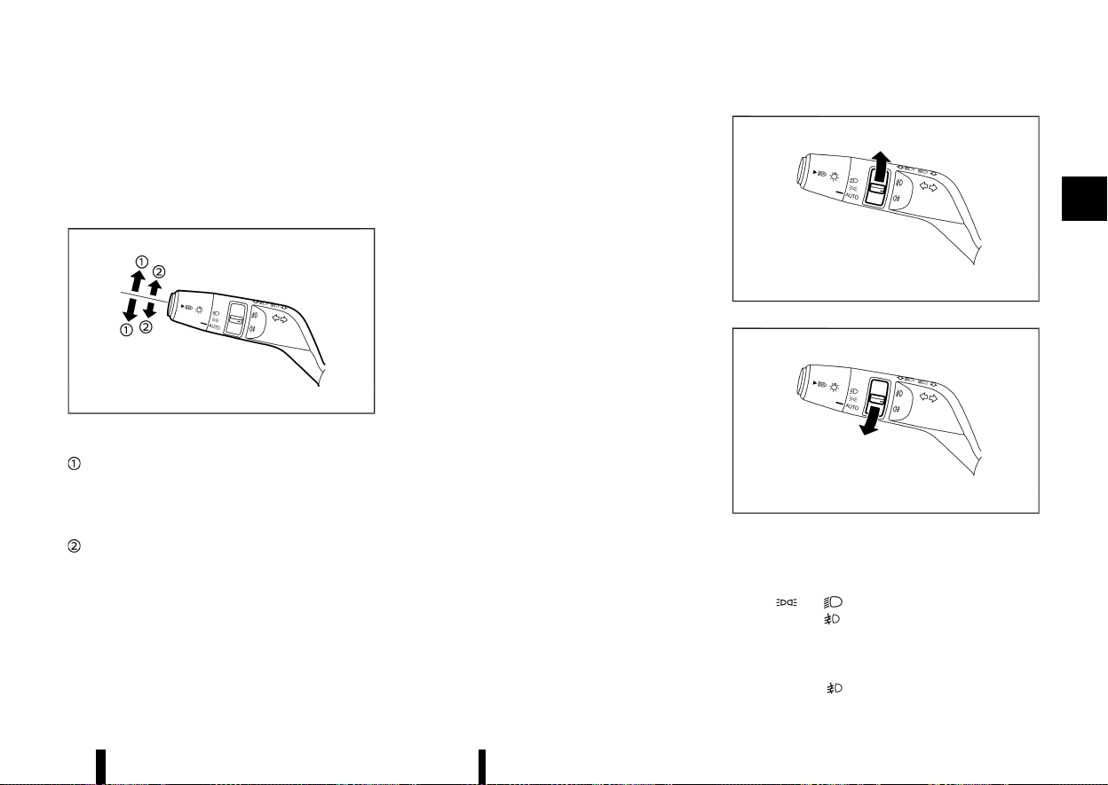
(119,1)
Automatic type (where fitted)
MEVT33A1-1F217A57-D519-4DD3-BD5F-E9139002FD81
The headlights are equipped with the automatic
levelling system. Headlight axis is controlled auto-
matically.
TURN SIGNAL SWITCH
MEVT33A1-DF12F6F8-A1D7-4024-A4DF-46D972E49E9C
MWBC0127X
Example
Turn signal
MEVT33A1-3CF2F736-4960-4B96-B5CF-1271A559F90A
Move the lever up or down to signal the turning
direction. When the turn is completed, the turn
signals cancel automatically.
Lane change signal
MEVT33A1-BCAE5264-DA08-4A37-B0F2-FDE7D90FCC8F
Move the lever up or down until the turn signal
begins to flash, but the lever does not latch, to
signal a lane change. Hold the lever until the lane
change is completed.
Move the lever up or down until the turn signal
begins to flash, but the lever does not latch, and
release the lever. The turn signal will automatically
flash three times.
Choose the appropriate method to signal a lane
change based on road and traffic conditions.
MEVT33A1-8A44D476-039A-440B-9B7F-71C22E22C8D1
MWBC0128X
MWBC0129X
Example
FRONT FOG LIGHTS (where fitted)
MEVT33A1-D1A305E5-A96D-4571-8501-B1992E1090A9
To turn the fog lights on, turn the headlight switch
to the
or position, then turn the fog light
switch to the
position.
To turn the fog lights on with the headlight switch
in the “AUTO” position, the headlights or front
clearance lights must be on, then turn the fog light
switch to the
position. (Once the headlights,
Instruments and controls 115
FOG LIGHT SWITCH
FOG LIGHT SWITCH
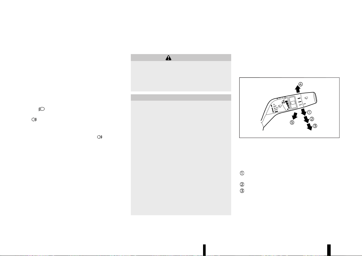
(120,1)
116 Instruments and controls
front clearance lights and fog lights are turned on
with the headlight switch in the "AUTO" position,
they continue to illuminate even if the surround-
ings become bright.
To turn them off, turn the fog light switch to the
OFF position.
REAR FOG LIGHT
MEVT33A1-069C2BB8-3B2A-47AB-8D3F-D9AD34EA9595
The rear fog light should be used only when
visibility is seriously reduced generally, to less than
100 m (328 ft)].
To turn the fog light on, turn the headlight switch
to the
position or turn the front fog lights
(where fitted) on, then turn the fog light switch to
the
position.
To turn the fog light on with the headlight switch
in the “AUTO” position, the headlights must be on,
then turn the fog light switch to the
position.
To turn off, turn the fog light switch to the OFF
position.
MEVT33A1-E3EA3376-5066-42DB-890F-056CE8D3AF95
WINDSCREEN WIPER AND WASHER OP-
ERATION
MEVT33A1-5D62D6DA-D084-4A1A-9D95-62ADEFE70EF9
WARNING
In freezing temperatures the washer solution
may freeze on the windscreen and obscure
your vision which may lead to an accident.
Warm windscreen with the defogger before
you wash the windscreen.
CAUTION
* Do not operate the washer continuously
for more than 30 seconds.
* Do not operate the washer if the reservoir
tank is empty.
* Do not fill the window washer reservoir
tank with washer fluid concentrates at full
strength. Some methyl alcohol based
washer fluid concentrates may perma-
nently stain the grille if spilled while filling
the window washer reservoir tank.
* Pre-mix washer fluid concentrates with
water to the manufacturer’s recom-
mended levels before pouring the fluid
into the window washer reservoir tank.
Do not use the window washer reservoir
tank to mix the washer fluid concentrate
and water.
* Do not operate the windscreen wiper while
the wiper arm is pulled up. The wiper arm
may be damaged.
If the windscreen wiper operation is interrupted
by snow or ice, the wiper may stop moving to
protect its motor. If this occurs, turn the wiper
switch to the OFF position and remove the snow
or ice that is on and around the wiper arms. In
approximately 1 minute, turn the switch on
again to operate the wiper.
MWAC0887X
The windscreen wiper and washer operates when
the ignition switch is in the ON position.
Push the lever down to operate the wiper at the
following speed:
AUTO — see “Rain-sensing auto wiper sys-
tem” (P.117).
Low — continuous low speed operation
High — continuous high speed operation
If the ignition switch is placed in the “OFF”
position while the wiper operates in the high
speed position, the wiper will not operate the
next time the ignition switch is placed in the
ON position. To operate the wiper, move the
WIPER AND WASHER SWITCH
WIPER AND WASHER SWITCH
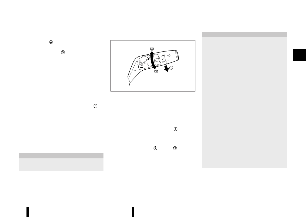
(121,1)
lever to any position other than high speed.
Push the lever up
to have one sweep operation
of the wiper.
Pull the lever toward you
to operate the washer.
Then the wiper will also operate several times.
The headlight cleaner (where fitted) will also
operate with operation of the windscreen washer.
(See “Headlight cleaner (where fitted)” (P.117).)
NOTE:
The Speed Dependent feature may be disabled.
For additional information, refer to “[Vehicle
Settings]” (P.86).
Headlight cleaner (where fitted)
MEVT33A1-31E21B37-5355-4A2B-8D5A-FBE393594AD9
Pull the lever toward the rear of the vehicle .
The headlight cleaner will operate with operation
of the windscreen washer.
* The headlight cleaner operates with the wind-
screen washer operation. This operation acti-
vates once each time the ignition switch is
turned off and on.
* After the first operation, the headlight cleaner
operates once at every fifth operation of the
windscreen washer.
CAUTION
Add the window washer fluid reservoir when
the fluid is at a low level.
RAIN-SENSING AUTO WIPER SYSTEM
MEVT33A1-C3DA0905-9EBF-4814-8E98-41180361A122
MWBC0049X
The rain-sensing auto wiper system can automa-
tically turn on the wipers and adjust the wiper
speed depending on the rainfall and the vehicle
speed by using the rain sensor located on the
upper part of the windscreen.
To set the rain-sensing auto wiper system, push
the lever down to the “AUTO” position
. The wiper
will sweep once while the ignition switch is in the
ON position.
The rain sensor sensitivity level can be adjusted by
turning the knob toward
(Low) or (High).
* High — High sensitive operation
* Low — Low sensitive operation
To turn the rain-sensing auto wiper system off,
push up the lever to the “OFF” position, or pull
down the lever to the other.
CAUTION
Do not touch the rain sensor and around it
when the wiper switch is in the “AUTO” position
and the ignition switch is in the ON position.
The wipers may operate unexpectedly and
cause an injury or may damage a wiper.
* The rain-sensing auto wipers are intended
for use during rain. If the switch is left in
the “AUTO” position, the wipers may oper-
ate unexpectedly when dirt, fingerprints,
oil film or insects are stuck on or around
the sensor. The wipers may also operate
when exhaust gas or moisture affect the
rain sensor.
* When the windscreen glass is coated with
water repellent, the speed of the rain-
sensing auto wipers may be higher even
though the amount of the rainfall is small.
* Be sure to turn off the rain-sensing auto
wiper system when you use a car wash.
* The rain-sensing auto wipers may not
operate if rain does not hit the rain sensor
even if it is raining.
* Using genuine wiper blades is recom-
mended for proper operation of the rain-
sensing auto wiper system. (See “Wind-
screen wiper blades” (P.436) for wiper
blade replacement.)
Instruments and controls 117
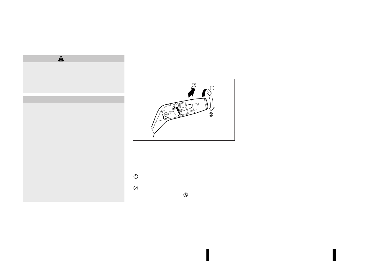
(122,1)
118 Instruments and controls
REAR WINDOW WIPER AND WASHER
OPERATION
MEVT33A1-0013655D-0D88-4D9F-87AB-B359910F5671
WARNING
In freezing temperatures the washer solution
may freeze on the rear window glass and
obscure your vision. Warm the rear window
with the defogger before you wash the rear
window.
CAUTION
* Do not operate the washer continuously
for more than 30 seconds.
* Do not operate the washer if the reservoir
tank is empty.
* Do not fill the window washer reservoir
tank with washer fluid concentrates at full
strength. Some methyl alcohol based
washer fluid concentrates may perma-
nently stain the grille if spilled while filling
the window washer reservoir tank.
* Pre-mix washer fluid concentrates with
water to the manufacturer’s recom-
mended levels before pouring the fluid
into the window washer reservoir tank.
Do not use the window washer reservoir
tank to mix the washer fluid concentrate
and water.
If the rear window wiper operation is interrupted
by snow or ice, the wiper may stop moving to
protect its motor. If this occurs, turn the wiper
switch to the OFF position and remove the snow
or ice that is on and around the wiper arms. In
approximately 1 minute, turn the switch on
again to operate the wiper.
MWAC0888X
The rear window wiper and washer operate when
the ignition switch is in the ON position.
Turn the switch clockwise from the OFF position to
operate the wiper.
Intermittent (INT) — intermittent operation
(not adjustable)
Low (ON) — continuous low speed operation
Push the switch forward
to operate the washer.
Then the wiper will also operate several times.
Reverse Link feature:
When the windscreen wiper switch is on, moving
the shift lever to the R (Reverse) position will
operate the rear window wiper.
NOTE:
The Reverse Link feature may be disabled. For
additional information, refer to “[Vehicle Set-
tings]” (P.86).
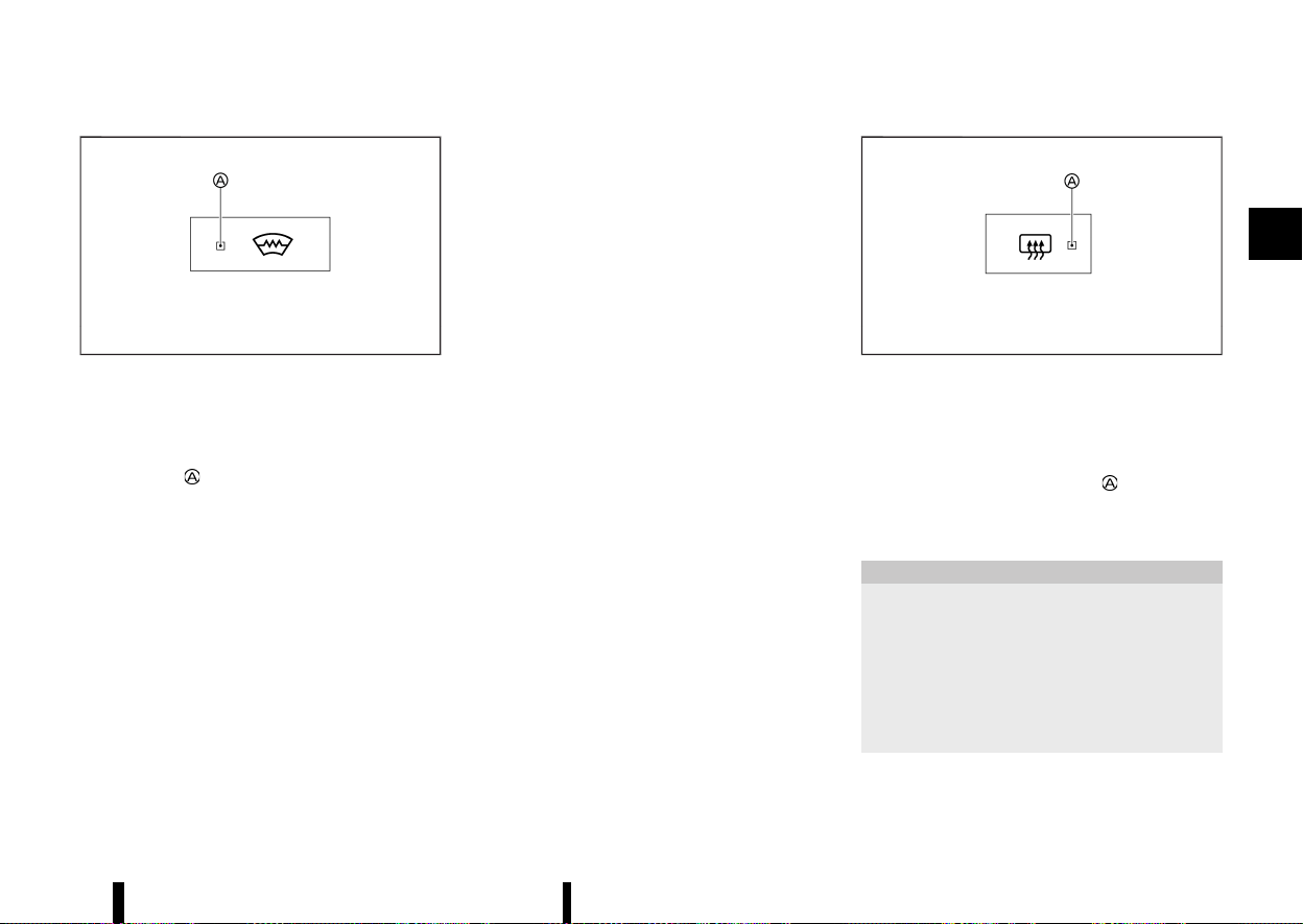
(123,1)
MEVT33A1-42DFB5C9-1242-42C6-9C81-3035F0339A9D
MWAC0956X
The heated windscreen button is located on the
front air conditioner control panel.
To defog/defrost the windscreen, start the engine
and push the heated windscreen button. The
indicator light
will illuminate.
Push the button again to turn the system off.
The system will turn off automatically after a
period of time. If the windscreen clears before this
time, push the button again to turn the system off.
NOTE:
* The system can only be activated while the
engine is running.
* Before activating the system make sure to
remove excess snow/ice from the wind-
screen.
* Electrical conductors embedded in the
windscreen provide the heating of the wind-
screen. If damage occurs to the windscreen
have the system checked by a NISSAN dealer
or qualified workshop.
* Reduced performance or deactivation of the
heated windscreen may be noticed to pre-
serve the battery. This is not a malfunction.
* NISSAN recommends using the system to
support defogging of the windscreen. For
more information, see “Heater and air con-
ditioner” (P.204).
* During use of the system, the Stop/Start
System is unavailable.
MEVT33A1-3B91CBF8-3714-4097-A2DD-A61CFF95B18A
MWAC0957X
Example
The defogger switch is located on the front air
conditioner control panel.
To defog/defrost the rear window glass and out-
side rearview mirrors, start the engine and push
the switch on. The indicator light
will illuminate.
Push the switch again to turn the defogger off.
It will automatically turn off in approximately 20
minutes.
CAUTION
* When operating the defogger continu-
ously, be sure to start the engine. Other-
wise, it may cause the battery to
discharge.
* When cleaning the inner side of the win-
dow, be careful not to scratch or damage
the electrical conductors on the surface of
the window.
Instruments and controls 119
HEATED WINDSCREEN (where fitted)
HEATED WINDSCREEN (where fitted)
DEFOGGER SWITCH
DEFOGGER SWITCH
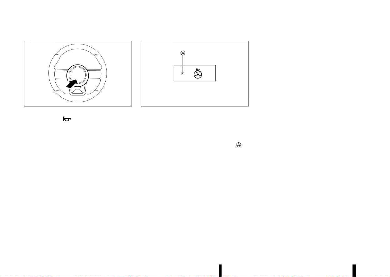
(124,1)
120 Instruments and controls
MEVT33A1-BCFDC961-0310-45F1-A715-1044C3AF17A3
MWAC0565X
The horn switch operates regardless of the
ignition switch position except when the battery is
discharged.
When the horn switch is pushed and held, the horn
will sound. Releasing the horn switch will cease the
horn sound.
MEVT33A1-33197EEF-5D77-4332-96A1-3D3EF363B858
MWAC0981X
Example
The heated steering wheel switch is located on the
front air conditioner control panel.
Push the heated steering wheel switch to warm
the steering wheel after the ignition switch is
placed in the ON position. The indicator light
will
illuminate. Push the switch again to turn the
system off.
If the surface temperature of the steering wheel is
below 20°C (68°F), the system will heat the steering
wheel and cycle off and on to maintain a tem-
perature above 20°C (68°F). The indicator light will
remain on as long as the system is on (approxi-
mately 30 minutes).
Push the switch again to turn the heated steering
wheel system off manually. The switch colour will
change from orange to white as the feature turns
from ON to OFF.
NOTE:
Once activated, your heated steering wheel will
automatically turn on and off to maintain a
temperature above 20°C (68°F).
When the temperature of the steering wheel is
above 50°C (122°F) and the heated steering
wheel switch is turned on, the system will not
heat the steering wheel. This is not a malfunc-
tion.
HORN
HORN
HEATED STEERING WHEEL
SWITCH (where fitted)
HEATED STEERING WHEEL
SWITCH (where fitted)

(125,1)
MEVT33A1-D3D3A560-DD20-4586-8F7C-D06E0297D4D0
The Rear Door Alert system functions under
certain conditions to indicate there may be an
object or passenger in the rear seat(s). Check the
seat(s) before exiting the vehicle.
The Rear Door Alert system is initially disabled. The
driver can enable the system using the vehicle
information display. (See “[Vehicle Settings]” (P.86).)
When the system is enabled:
* The system is activated when a rear door is
opened and closed. When the vehicle is started
and the system is activated, a visual message
appears in the vehicle information display. (See
“26. [Rear Door Alert is activated indicator]
(where fitted)” (P.95).)
* If a rear door is opened and closed but the
vehicle is not driven, the system will not be
activated. A rear door must be opened and
closed and the car driven for the system to
activate.
* The time interval to activate the system
between when the rear door is opened and
closed and the vehicle is started is about 10
minutes. A longer interval does not indicate a
malfunction.
When the Rear Door Alert system is activated:
* When the driver puts the vehicle in the P (Park)
position, a notification message appears in the
vehicle information display with the options to
[Dismiss Message] or [Disable Alert] if desired.
— Select [Disable Alert] to temporarily disable
for that stop.
— No selection or [Dismiss Message] will keep
the alert enabled for that stop.
* If the alert is enabled when a driver exits the
vehicle, a message will appear in the vehicle
information display that states [Reminder
Check Rear Seat].
If [Horn & Alert] setting is selected:
— An audible horn sound will occur after a
short time unless a rear door is opened and
closed within a short time to deactivate the
alert.
— If the doors are locked before the alert is
deactivated by opening a rear door, the
horn will sound.
— If the back door is opened before a rear
door is opened, the horn will be delayed
until after the back door is closed.
NOTE:
If [Alert Only] setting is selected, the message
alert will still be shown in the vehicle information
display but the horn will not sound.
WARNING
* If the driver selects [Disable Alert], no
audible alert or a message will be provided
regardless of rear door open/close status.
* There may be times when there is an
object or passenger in the rear seat(s) but
the audible alert does not sound. For
example, this may occur if rear seat pas-
sengers enter or exit the vehicle during a
trip.
* The system does not directly detect ob-
jects or passengers in the rear seat(s).
Instead, it can detect when a rear door is
opened and closed, indicating that there
may be something in the rear seat(s).
NOTE:
There may be times when the horn sounds but
there are no objects or passengers in the rear
seat(s).
(See “26. [Rear Door Alert is activated indicator]
(where fitted)” (P.95).)
Instruments and controls 121
REAR DOOR ALERT (where fitted)
REAR DOOR ALERT (where fitted)
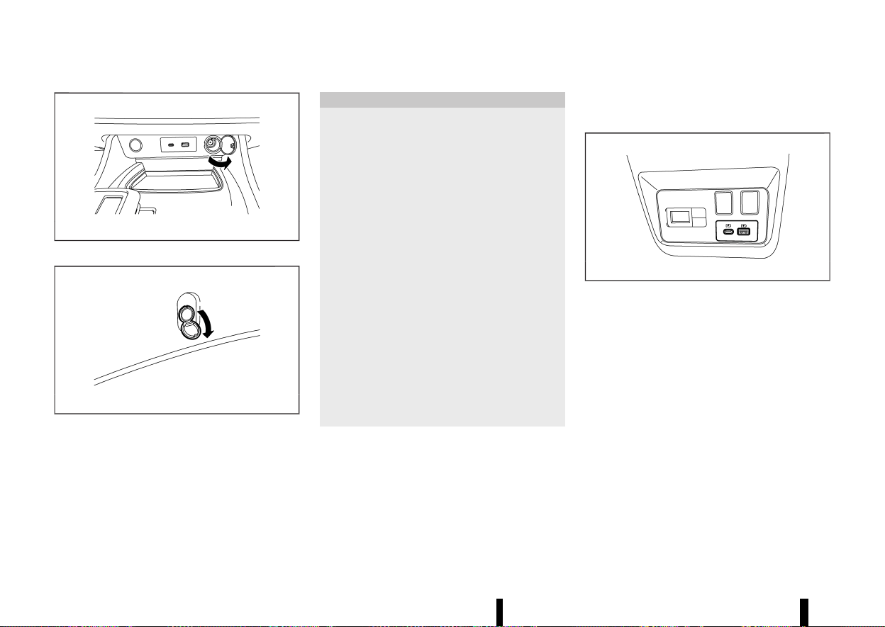
(126,1)
122 Instruments and controls
MEVT33A1-850FEE13-D4FF-4D25-97B5-E92230D21302
MWAC0325X
Instrument panel (example)
MWAC0972X
Luggage area (example)
The power outlets is located in the lower part of
the instrument panel* and in the luggage area.
*: The layout in the illustration is for the Left-Hand
Drive (LHD) model. For the Right-Han Drive (RHD)
model, the outlet is located on the opposite side.
CAUTION
* The outlet and plug may be hot during or
immediately after use.
* Do not use with accessories that exceed a
12 volt, 120W (10A) power draw. Do not use
double adapters or more than one elec-
trical accessory.
* Use power outlet with the engine running
to avoid discharging the vehicle battery.
* Avoid using power outlet when the air
conditioner, headlights or rear window
defogger is on.
* This power outlet is not designed for use
with a cigarette lighter unit.
* Push the plug in as far as it will go. If good
contact is not made, the plug may over-
heat.
* Before inserting or disconnecting a plug,
be sure the electrical accessory being used
is turned OFF.
* When not in use, be sure to close the cap.
Do not allow water or any liquid to contact
the outlet.
USB (Universal Serial Bus) CHARGING
CONNECTOR (where fitted)
MEVT33A1-F92B57E4-B6FF-4777-91E1-880F1FD5F9F8
MWAC0326X
Example
The USB charging connector is located on the
back of the centre console box.
The USB charging connector can be used only for
charging an external device.
Connect a USB device into the connector. Char-
ging will start automatically. For USB charging
connector (for USB Type-A), maximum output is up
to 5 volt, 12W, 2,4A. For USB charging connector (for
USB Type-C), maximum output is up to 5 volt, 15W,
3A.
The external device will be charged continuously
while the ignition switch is in the ON position.
Some mobile devices cannot be charged depend-
ing on their specifications.
POWER OUTLETS
POWER OUTLETS
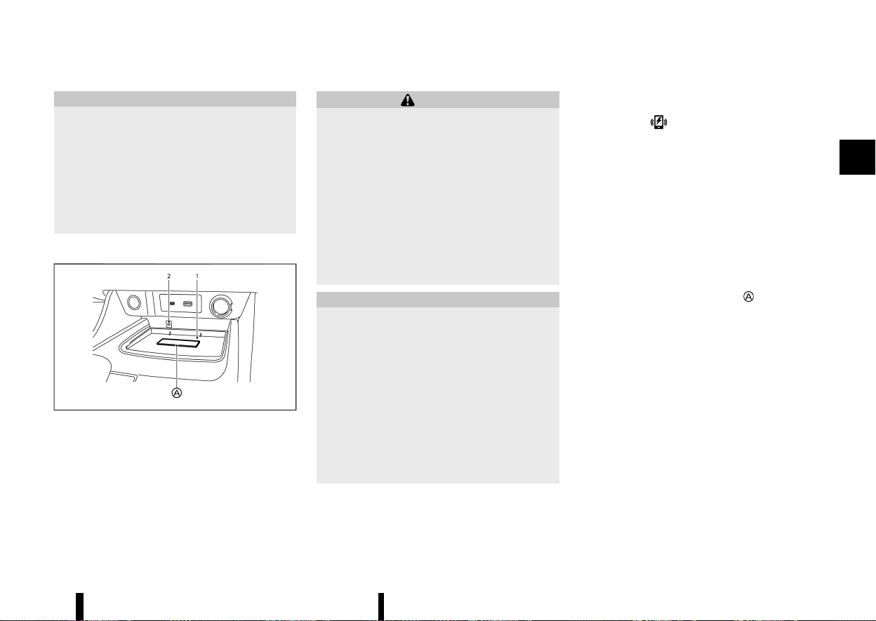
(127,1)
CAUTION
* Do not force a USB device into the con-
nector. Depending on the USB connector,
inserting the USB device tilted or upside
down may damage the connector. Make
sure that the USB device is connected
correctly into the connector.
* Do not use a reversible USB cable. Using
the reversible USB cable may damage the
connector.
WIRELESS CHARGER (where fitted)
MEVT33A1-8C56C6CB-4197-4E63-8A1C-C2EA53136748
MWAC0327X
Example
1. Charging pad
2. Indicator
The wireless charger is located on the front of the
centre console. Lay the smartphone on the pad of
the wireless charger. Charging will start automa-
tically. The smartphone will be charged continu-
ously while the ignition switch is in the ON position.
WARNING
* Never put metallic materials between the
wireless charger and a smartphone.
* Those who use a pacemaker or other
medical equipment should contact the
electric medical equipment manufacturer
for the possible influences before use.
* Never put cloth over the smartphone dur-
ing charging process.
* Never charge a smartphone when it is wet.
* Never put metallic materials or small
goods such as a cigarette lighter, Intelli-
gent Key or memory drive.
CAUTION
* Do not put an RFID/NFC/credit card be-
tween the wireless charger and a smart-
phone. This could cause data corruption in
the card.
* Do not use the wireless charger with dust
accumulated or dirt on the pad.
* Do not hit the surface of the wireless
charger.
* Do not spill liquid (water, drinks, etc.) on
the charging pad.
* Do not use grease, oil or alcohol for
cleaning charging pad.
Wireless charger Indicator
MEVT33A1-D6A4C239-0F9C-49E3-8DBF-C47AACDB7620
The indicator will illuminate in orange when
the charging process is started.
When the charging has completed, the indicator
illuminates in green.
If a malfunction occurs or the charging process
has stopped, the indicator will blink in orange for 8
seconds then turn off.
Operation of the wireless charger
MEVT33A1-6569096D-CD21-427D-BC4A-D15F679A08E2
To use the wireless charger, it is necessary to seat
the smartphone well within the charging pad. To
maximize charging performance, ensure the
smartphone is fully seated on the centre of the
charging pad over the “Qi” logo
. Because the
location of the power receiver may vary depending
on the smartphone, you will need to try and find
the area that suits your smartphone.
Because some smartphone cases or accessories
may adversely affect charging, remove them
before wireless charging.
Turn off the vibration function of the smartphone
before wireless charging.
NOTE:
* Only a Qi compatible smartphone can be
used.
* The smartphone or the wireless charger
may be warmed during charging process
and the charging may stop by the protection
function of the smartphone or the wireless
charger. This is not a malfunction. If this
occurs, restart charging after the smart-
phone or the wireless charger cooled down.
Instruments and controls 123

(128,1)
124 Instruments and controls
The indicator will blink in orange then turn
off.
* The wireless charging process may be
stopped by the status of the smartphone
(battery temperature, etc.).
* If a radio noise interference occurs during
charging process, put the smartphone onto
the centre (“Qi” logo) position of the wireless
charger.
* The wireless charging process will stop
during process of searching the Intelligent
Key.
* The wireless charging process will not be
started when a USB (Universal Serial Bus)
cable is connected to the smartphone. The
indicator may illuminate in orange or blink if
the smartphone is put on the wireless
charger with a USB cable connected. How-
ever, charging is not performed.
* Depending on the type of the smartphone,
the indicator may remain illuminated in
orange even when the charging process
has been completed.
MEVT33A1-ACBEA04E-07DC-4FC6-9000-62282BECF92A
Your vehicle is equipped with the 112-based in-
vehicle emergency services call system (eCall). In
the event of a serious road accident emergency an
automatic call can be made to the emergency
services operator. The system can also be used
manually to call the emergency services operator.
The 112-based eCall service is a public service of
general interest and is accessible free of charge.
NISSAN is responsible only for the emergency
communication system technical performance in
the event of an accident within the warranty
period.
AUTOMATIC ECALL
MEVT33A1-E1D3A762-310C-438F-8020-8CC2B437A161
If the air bag control unit detects a frontal collision,
side collision or rear collision (where fitted) the
system automatically places an emergency call to
the emergency call centre. At the same time, the
vehicle information is also transferred. Once an
emergency call is received by the emergency call
centre, the operator tries to talk to the vehicle’s
occupant.
NOTE:
* During the emergency call, the volume of the
voice of the operator cannot be adjusted.
* During the emergency call, the volume of the
vehicle audio will be muted.
The eCall system is always enabled by default. It is
activated automatically by means of in-vehicle
sensors in the event of a severe accident.
The eCall system is not traceable and is not subject
to any constant tracking in its normal operational
status. Data in the internal memory of the system
is not available outside the in-vehicle system to
any entities before the eCall is triggered.
Any processing of personal data through the 112-
based eCall in-vehicle system shall comply with
the personal data protection rules provided for in
Directives 95/46/EC and 2002/58/EC of the Eur-
opean Parliament and of the Council, and in
particular, shall be based on the necessity to
protect the vital interests of the individuals in
accordance with Article7(d) of Directive 95/46/EC.
Processing of such data is strictly limited to the
purpose of handling the emergency eCall to the
single European emergency number 112.
Recipients of data processed by the 112-based
eCall in-vehicle system are the relevant public
safety answering points designated by the respec-
tive public authorities of the country on which
territory they are located, to first receive and
handle eCalls to the single European emergency
number 112.
The following information will be sent to the
emergency call centre by the vehicle emergency
call system if a collision occurs:
* Vehicle Identification Number (VIN)
* Vehicle type
* Activation type (Automatic/Manual)
* Call type (Test/Emergency)
* Position (Trusted/Low confidence)
* Time stamp (when the collision or event
occurred)
* Last three vehicle locations, and vehicle direc-
tion
EMERGENCY SERVICES CALL
ECALL/SOS SYSTEM (where fitted)
EMERGENCY SERVICES CALL
ECALL/SOS SYSTEM (where fitted)
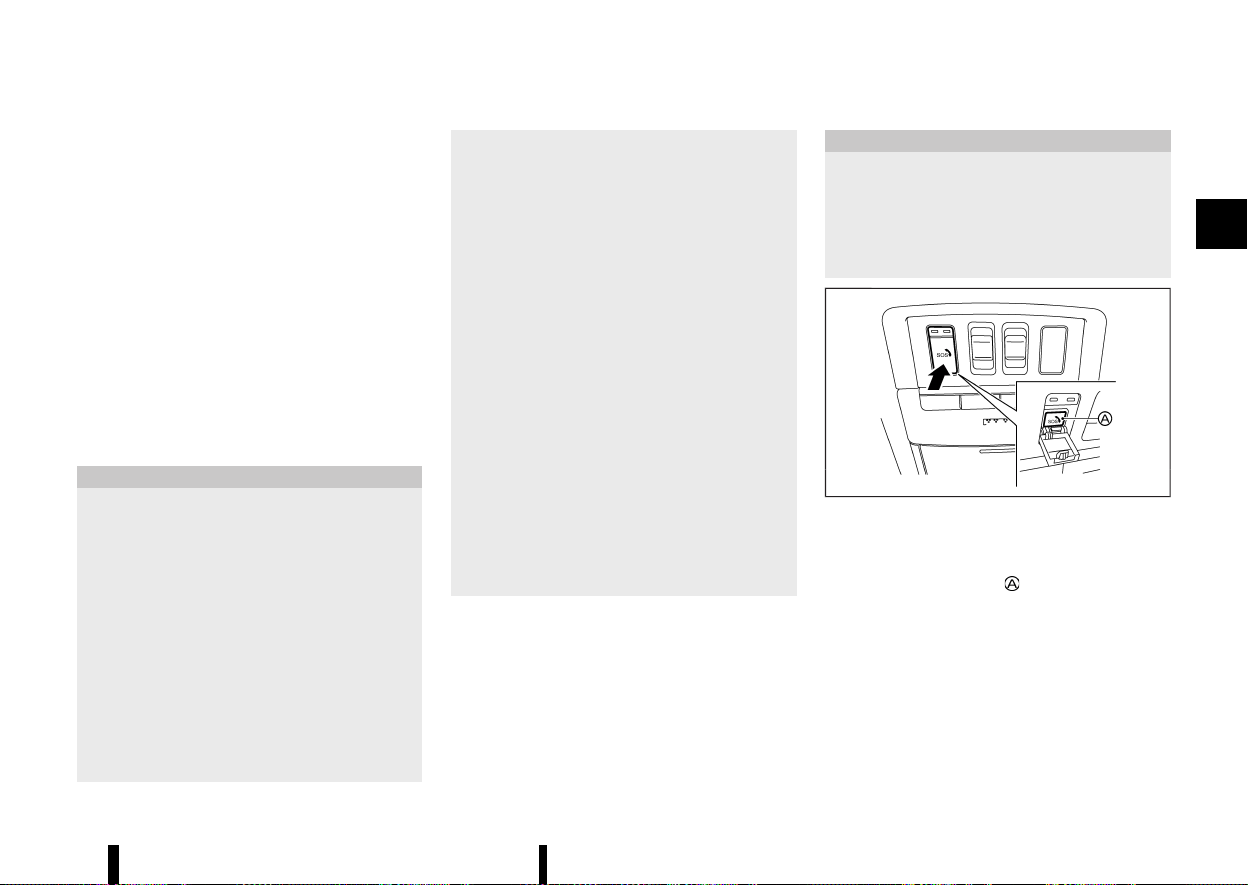
(129,1)
* Vehicle speed
* Number of passengers (where fitted)
The 112-based eCall in-vehicle system is designed
in such a way as to ensure that data in the system
internal memory is automatically and continuously
removed.
The vehicle location data is constantly overwritten
in the internal memory of the system so as always
to keep maximum of the last three up-to-date
locations of the vehicle necessary for the normal
functioning of the system.
The log of activity data in the 112-based eCall in-
vehicle system is kept for no longer than necessary
for attaining the purpose of handling the emer-
gency eCall and in any case not beyond 13 hours
from the moment an emergency eCall was in-
itiated.
CAUTION
* The intelligent emergency call will only be
triggered if the vehicle air bag system is
activated during the collision.
* If the intelligent emergency call has been
triggered, please bring your vehicle to a
NISSAN dealer or qualified workshop. This
is necessary because the intelligent emer-
gency call system needs to be reset to
avoid any unintended eCall being made.
* The mobile network provider that man-
ages the connection from the vehicle to
the emergency call centre is specified and
controlled outside of the vehicle emer-
gency call system.
* Within the first minute of any emergency
call the operator will determine if the call is
genuine. Should the operator determine it
is a nongenuine call they will stop the call,
making no further attempts to call the
vehicle back. This action does not prevent
the occupant(s) of the vehicle from making
a further manual emergency call.
The emergency call function cannot be used in
the following conditions:
* The vehicle is outside the area where
mobile network service is receivable.
* The vehicle is in a location with poor signal
reception such as tunnels, underground
parking garages, between buildings or in
mountainous areas.
* The TCU (Telematics Control Unit) or other
systems of your vehicle are not working
properly.
* The available mobile network provider at
the location of the vehicle is not specified
for emergency call usage.
* The communication line of the emergency
call centre is busy.
MANUAL ECALL (SOS button)
MEVT33A1-C0F90624-BE9D-4230-8CC6-E1D2868A9AF2
The manual eCall can be performed with the
ignition switch placed in the "ON" position, by
pushing the SOS button located near the map
lights.
After the ignition switch is placed in the "OFF"
position, if an emergency call was not made, the
eCall system is turned off.
CAUTION
* Park the vehicle in a safe location and
apply the parking brake before operating
the SOS button.
* Use this service only in case of an emer-
gency. There may be a penalty for inap-
propriate use of the service.
MWAC0768X
1. Place the ignition switch in the "ON" position.
2. Push to open the SOS cover.
3. Push the SOS button
. An emergency call is
sent to the emergency call centre. At the same
time, the vehicle information is also trans-
ferred.
4. When the call is connected, you can speak to
the emergency support staff.
If you want to cancel the emergency call, push and
hold the SOS button for a few seconds. The call
cannot be cancelled after connection.
Instruments and controls 125
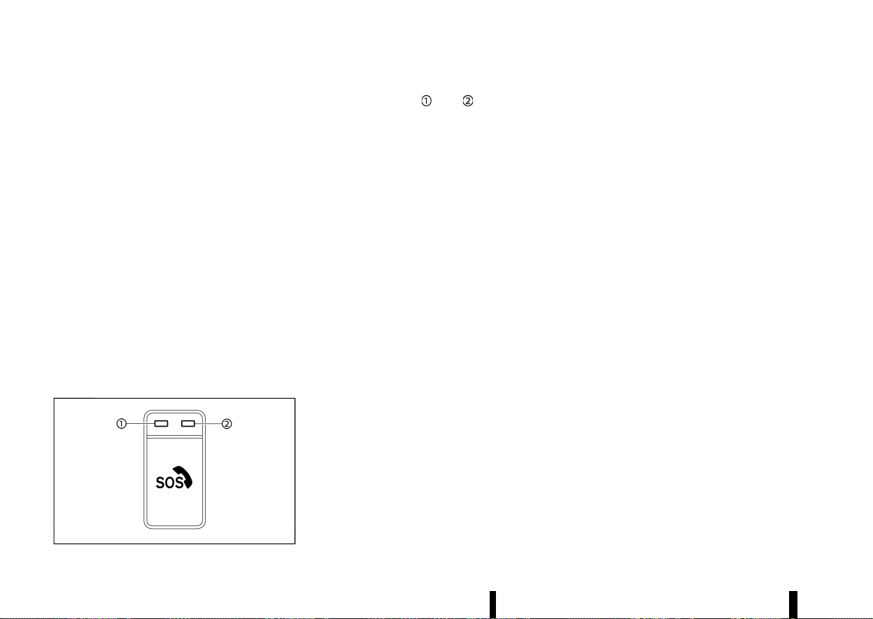
(130,1)
126 Instruments and controls
NOTE:
* During the emergency call, the volume of the
voice of the operator cannot be adjusted.
* During the emergency call, the volume of the
vehicle audio will be muted.
* After the SOS button is pushed, it may take
some time until the system initiates con-
nection, depending on the technical envir-
onment and whether the TCU is being used
by other services.
* To avoid disconnecting the call, do not turn
the engine off.
* During the emergency call Bluetooth®
Hands-Free Phone connection will be dis-
abled and phone operation will only be
available by mobile phone.
* If the emergency call is disconnected for
some reason the emergency call centre may
call back. This action does not prevent the
occupant(s) of the vehicle from making
another manual emergency call.
SYSTEM STATUS INDICATOR
MEVT33A1-BFE6A846-7A80-4898-BA6B-4B80C7AFDFB7
MWAC0760X
The indicator lights and above the SOS
button indicate the status of the vehicle emer-
gency call system. If the indicator light is illumi-
nated red or no indicator light is illuminated the
emergency call may not connect to the emergency
call centre when the SOS button is pressed. Also an
intelligent Emergency call may not be sent when a
collision occurs.
* During vehicle start up the system operates
self diagnostics and the red indicator light is
illuminated for up to 15 seconds.
* At any other time if the red indicator light is
illuminated contact a NISSAN dealer or quali-
fied workshop for assistance. In the event of a
critical system failure that would disable the
112-based eCall in-vehicle system, the red
indicator light is illuminated as a warning.
NOTE:
If the indicator light is illuminated red or no
indicator light is illuminated, emergency ser-
vices (such as the police or other agencies)
should be contacted using other normal com-
munication devices (for example a phone) in the
event of an accident.
MODALITIES FOR EXERCISING DATA
SUBJECT’S RIGHTS
MEVT33A1-AF741674-4CBF-483A-B895-871DC99A73B9
The data subject (the vehicle’s owner) has a right
of access to data and as appropriate to request
the rectification, erasure or blocking of data,
concerning him or her, the processing of which
does not comply with the provisions of Directive
95/46/EC. Any third parties to whom the data have
been disclosed have to be notified of such
rectification, erasure or blocking carried out in
compliance with this Directive, unless it proves
impossible or involves a disproportionate effort.
The data subject has a right to complain to the
competent data protection authority if he or she
considers that his or her rights have been infringed
as a result of the processing of his or her personal
data.
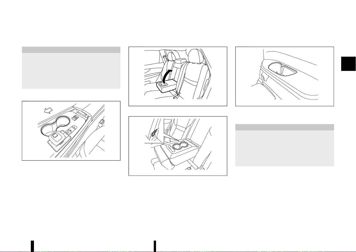
(131,1)
MEVT33A1-11FFEB74-6D4E-4717-B00A-F5FBAB2E5908
CUP HOLDERS
MEVT33A1-FC8FAFBC-BCD6-43B2-98A8-26203EF5F9DB
CAUTION
* Avoid abrupt starting and braking when
the cup holder is being used to prevent
spilling the drink. If the liquid is hot, it can
scald you or your passenger.
* Use only soft cups in the cup holder. Hard
objects can injure you in an accident.
Front
MEVT33A1-1A4FBEC5-2F7E-4330-AFDC-3E00F421B6AB
MWAC0973X
Centre console
Second row seat
MEVT33A1-BF2AA628-64D0-45CC-986A-8EB2E1457628
MJVI0873X
Two row model
MWAC0974X
Three row model
The cup holders are located in the fold-down
armrest.
Third row seat (where fitted)
MEVT33A1-D1F8A193-4D3F-45F3-BC7A-EF03B80C356F
MWAC0755X
SOFT BOTTLE HOLDERS
MEVT33A1-DB73E00A-24BD-4615-AB61-2C372E74F0A9
CAUTION
* Do not use bottle holder for any other
objects that could be thrown about in the
vehicle and possibly injure people during
sudden braking or an accident.
* Do not use bottle holder for open liquid
containers.
Instruments and controls 127
STORAGE
STORAGE
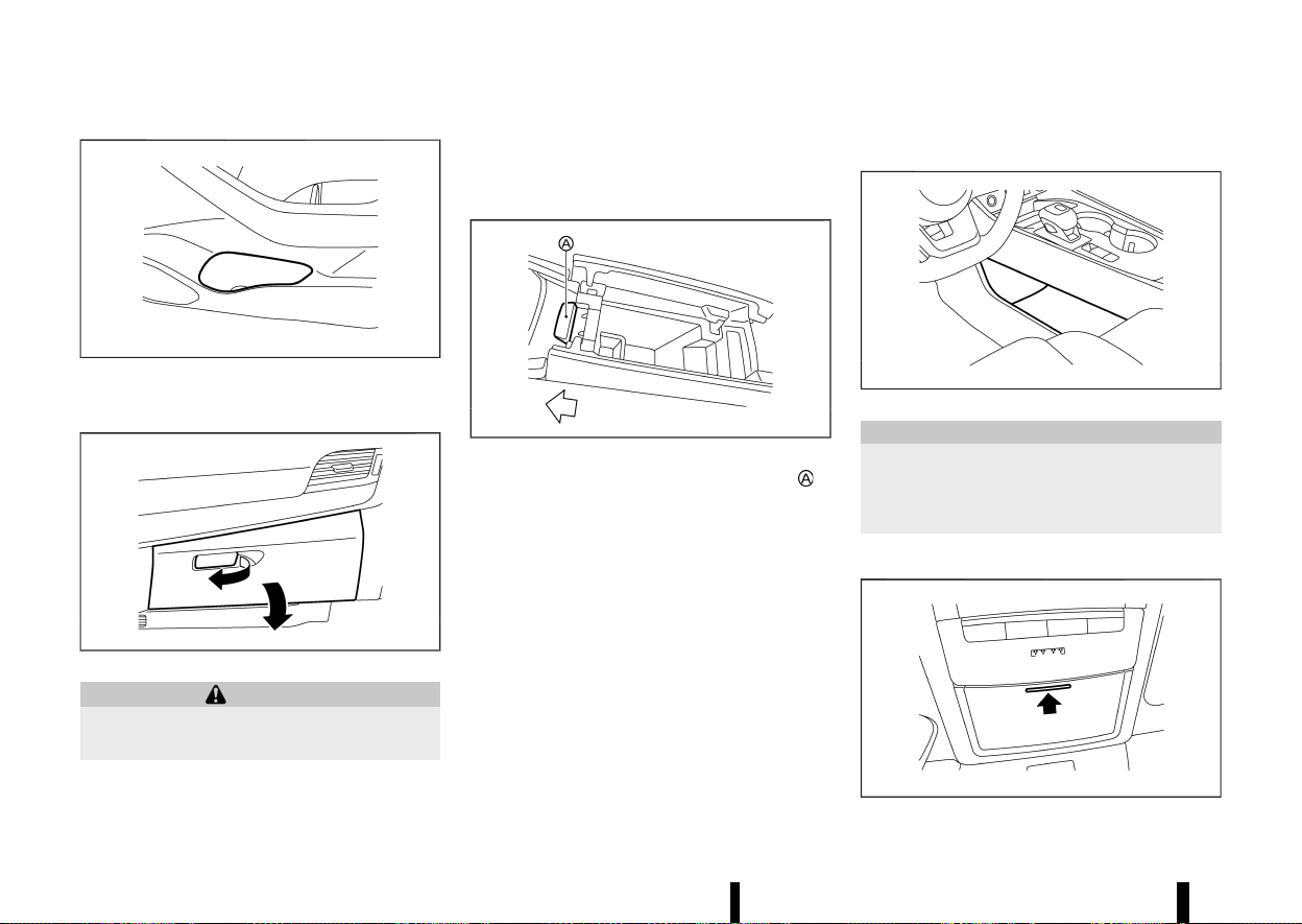
(132,1)
128 Instruments and controls
MWAC0423X
Door (front and second row seats)
GLOVE BOX
MEVT33A1-EA635502-9936-47A9-B2CA-4F1ACC30F00B
MWAC0532X
WARNING
Keep glove box lid closed while driving to help
prevent injury in an accident or a sudden stop.
To open the glove box, pull the handle.
To close, push the lid in until the lock latches.
The glove box light (where fitted) illuminates when
the headlight switch is turned on.
CONSOLE BOX
MEVT33A1-ADA88A77-3AEE-4F5D-BBFF-71DB3B593347
MWAC0424X
To open the console box lids, push the knob in
the rearward.
To close, push each lid down until the lock latches.
If something is put on top of either side of the lids,
that side lid may not open. Remove any object and
push the knob again to open the lid.
LOWER CONSOLE TRAY
MEVT33A1-AF98C85D-4779-46E5-939C-EBBAE6B14863
MWAC0975X
CAUTION
Do not place any objects in lower console tray
that could be thrown about in the vehicle and
cause injury during sudden braking or colli-
sion.
SUNGLASSES HOLDER
MEVT33A1-9740085B-7C25-48E2-9040-6492C96040BC
MWAC0425X
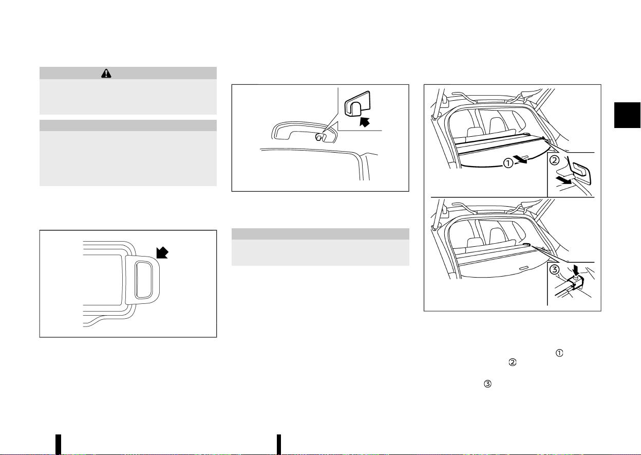
(133,1)
WARNING
Keep the sunglasses holder closed while driv-
ing to avoid obstructing the driver’s view and
to help prevent an accident.
CAUTION
* Do not use for anything other than sun-
glasses.
* Do not leave sunglasses in the sunglasses
holder while parking in direct sunlight. The
heat may damage the sunglasses.
To open the sunglasses holder, push and release.
Only store one pair of sunglasses in the holder.
CARD HOLDER
MEVT33A1-176CE38E-4DA7-4D06-862E-0B740A92232E
MWAC0490X
Slide a card in the card holder.
COAT HOOKS
MEVT33A1-14BC9462-D0C7-4458-822C-8AB095F87999
MSIC3505
The coat hook is located above the rear side
window.
CAUTION
Do not apply a total load of more than 1 kg (2
lb) to the hook.
TONNEAU COVER
MEVT33A1-8A96D1DE-86B5-4930-A671-18AAE82748CD
MWAC0329X
The tonneau cover keeps the luggage compart-
ment contents hidden from the outside.
To use the tonneau cover, pull it out
and insert
both sides to the guide
.
To remove the tonneau cover, stow the cover and
push the button
.
Instruments and controls 129
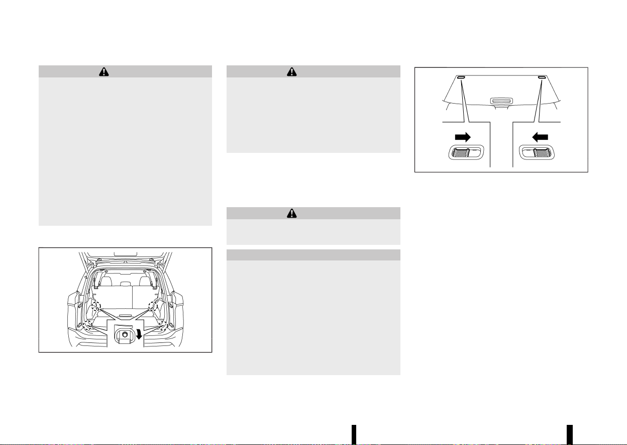
(134,1)
130 Instruments and controls
WARNING
* Never put anything on the tonneau cover,
no matter how small. Any object on it could
cause an injury in an accident or sudden
stop.
* Do not leave the tonneau cover in the
vehicle with it disengaged from the holder.
* The child restraint top tether strap may be
damaged by contact with the tonneau
cover or items in the luggage area. Re-
move the tonneau cover from the vehicle
or secure it in the luggage area. Also
secure any items in the luggage area. Your
child could be seriously injured or killed in
a collision if the top tether strap is
damaged.
LUGGAGE HOOKS
MEVT33A1-EA4A76B1-7DD2-46D6-9893-57F9CDC1A8E5
MWAC0534X
To use the hook, pull it down as illustrated.
WARNING
* Always make sure that the cargo is prop-
erly secured. Use the suitable ropes and
hooks.
* Unsecured cargo can become dangerous
in an accident or sudden stop.
* Do not apply a total load of more than 3 kg
(7 lb) to a single hook.
ADJUSTABLE LUGGAGE FLOOR (where
fitted)
MEVT33A1-5C20B0EA-9D07-4B88-995D-16F0BDCFAD16
You can use the luggage compartment in different
ways using the adjustable luggage boards.
WARNING
Do not put objects heavier than 75 kg (165 lbs)
on the load floor while in the upper position.
CAUTION
* Do not push the front edge of the luggage
board forcibly. Doing so may cause the
luggage board to be tilted, resulting in
personal injury.
* Do not handle the luggage board forcibly
as this may deform it.
* While in the upper position, do not recline
the seatbacks.
* Do not place cargo higher than the seat-
backs. In a sudden stop or collision, un-
secured cargo could cause personal injury.
MWAC0527X
Before moving the rear (outer) luggage board,
release the lock on the both sides of the board as
shown (where fitted).
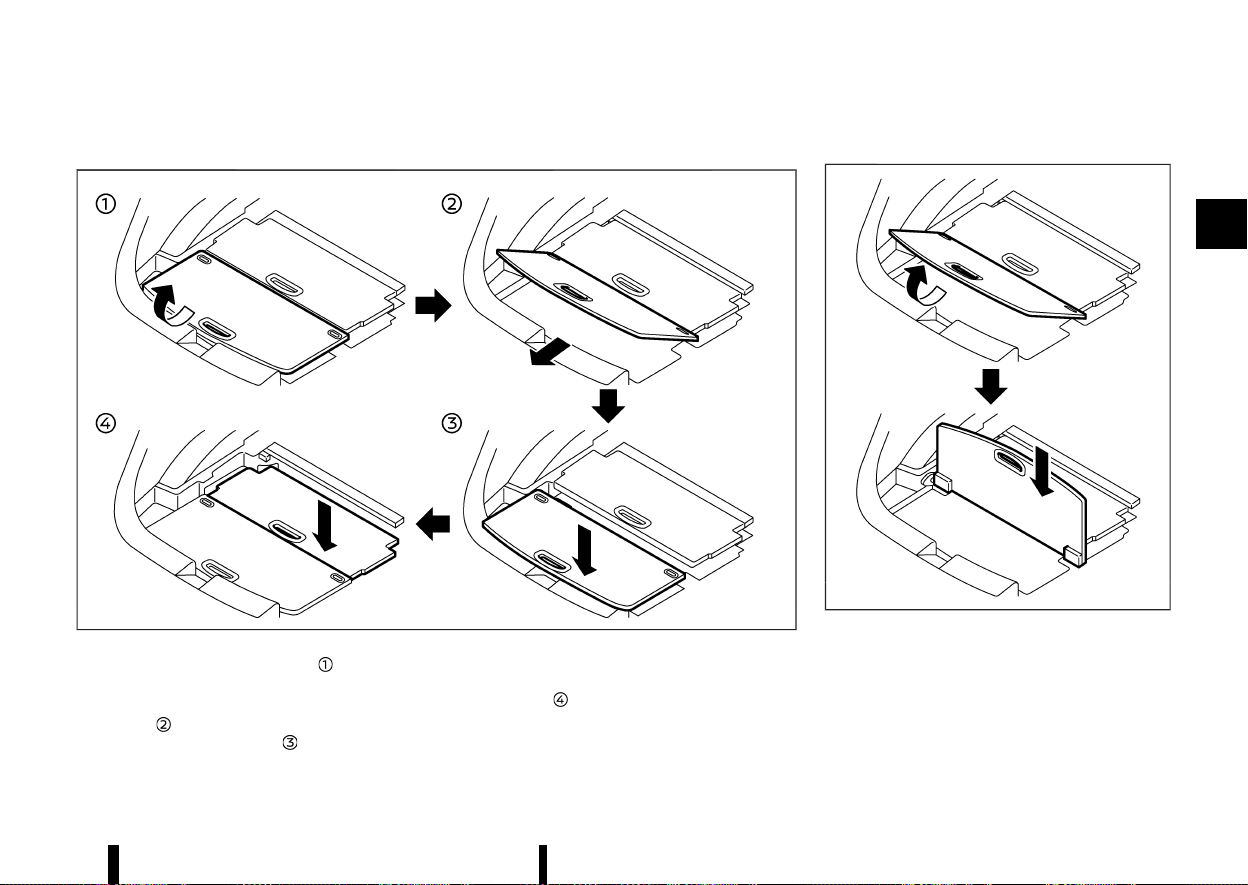
(135,1)
Two-stage mode
MEVT33A1-7972901E-CE07-46FB-9900-F1147087E205
MWAC0328X
1. Pull the rear board upward to approxi-
mately 30°.
2. Pull the rear board toward the rear of the
vehicle
and then push it into the bottom of
the luggage under space
.
3. Pull up the front (inner) board and push it into
the bottom of the luggage under space in the
same way
.
Vertical mode
MEVT33A1-8EACB7D3-2B7A-49FD-9D33-3CA03A6752EB
MWAC0526X
1. Pull the rear board upward to 90°.
2. Push down the board until it stops.
Instruments and controls 131
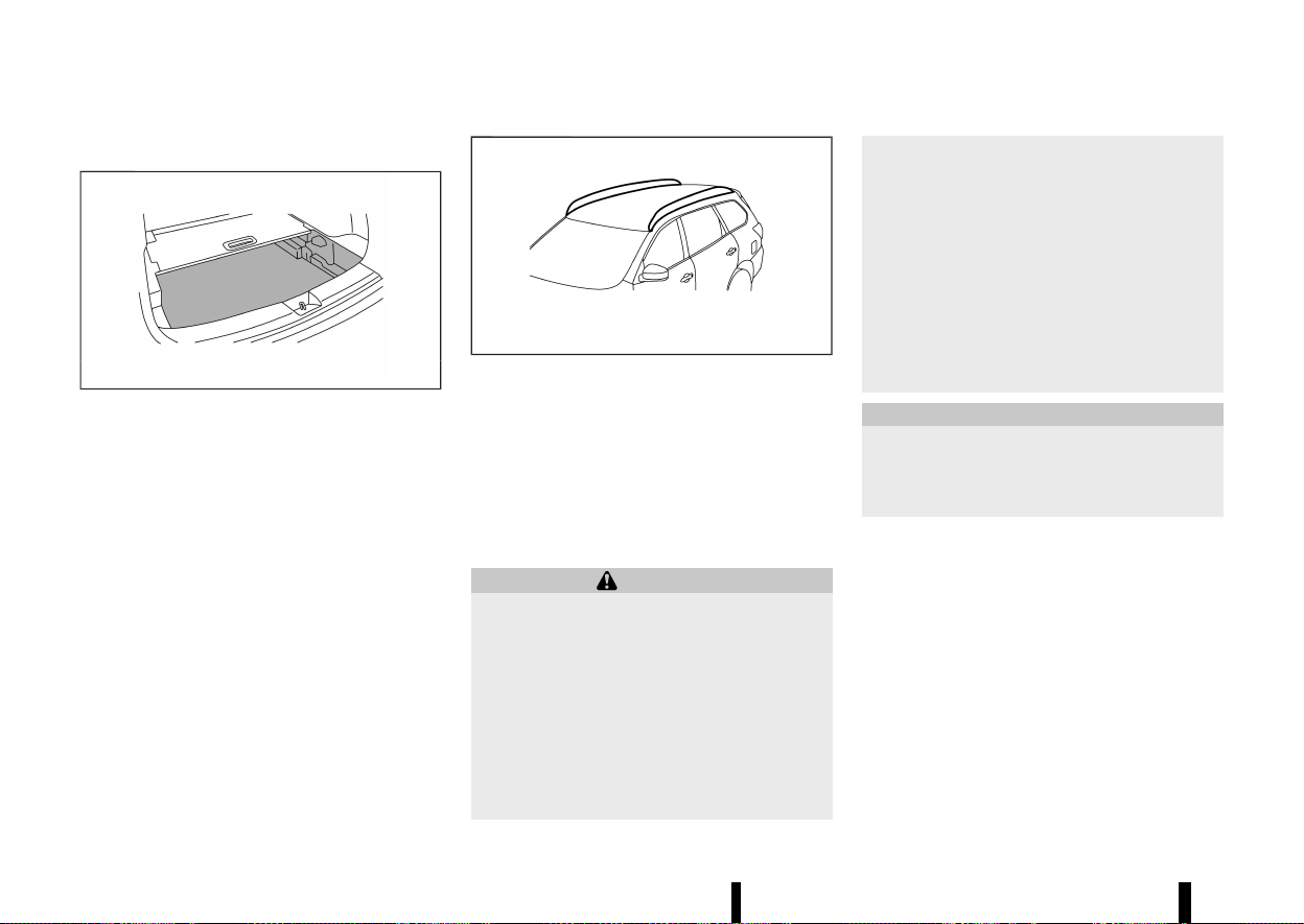
(136,1)
132 Instruments and controls
LUGGAGE UNDER SPACE
MEVT33A1-7FDEE1B0-6C2D-44A2-9FB4-EC653294A6A1
MWAC0561X
Example
To use the luggage under space, pull off the board.
MEVT33A1-0E8ADE11-9CF2-4318-863C-208E8323D6BE
MWAC0889X
Do not apply any load directly to the roof side rails.
Cross bars must be installed before applying load/
cargo/luggage to the roof of the vehicle. For
additional information, it is recommended that
you contact a NISSAN dealer or qualified work-
shop.
The service load capacity for the roof side rails is
100 kg (221 lb), however do not exceed the
accessory cross bars load capacity.
WARNING
* Always install the cross bars onto the roof
side rails before loading cargo of any kind.
Loading cargo directly onto the roof side
rails or the vehicle’s roof may cause vehicle
damage.
* Drive extra carefully when the vehicle is
loaded at or near the cargo carrying
capacity, especially if the significant por-
tion of that load is carried on the cross
bars.
* Heavy loading of the cross bars has the
potential to affect the vehicle stability and
handling during sudden or unusual hand-
ling manoeuvres.
* Roof rack cross bars should be evenly
distributed.
* Do not exceed maximum roof rack cross
bars load.
* Properly secure all cargo with ropes or
straps to help prevent it from sliding or
shifting. In a sudden stop or collision,
unsecured cargo could cause personal
injury.
CAUTION
Use care when placing or removing items from
the roof rack. If you cannot comfortably lift the
items onto the roof rack from the ground, use
a ladder or a stool.
ROOF RACK (where fitted)
ROOF RACK (where fitted)
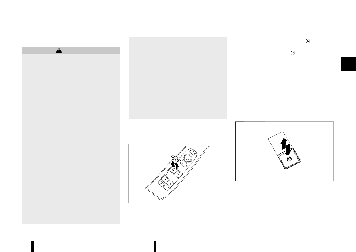
(137,1)
MEVT33A1-ECC58B2D-F250-41F5-B8E8-7EBD4B79C5CA
POWER WINDOWS
MEVT33A1-6A23709F-5277-4229-B1AD-2B7DC859B673
WARNING
The driver is always responsible for all the
power window operation including passen-
ger’s operation. Be sure to observe the follow-
ing warnings for safety.
* Never allow anyone to extend any portion
of their body or objects out of the opening
while the vehicle is in motion. Otherwise
they may be seriously damaged by coming
into contact with objects outside the ve-
hicle or when abruptly braking.
* Make sure that all passengers have their
hands, etc. inside the vehicle before oper-
ating the windows. Do not intentionally
activate the auto-reverse function. If their
hands or faces are caught in the windows,
it could cause serious injury.
* Never allow children to operate the power
window. Improper operation by children
could lead to an accident. Depress the
window lock button since children or other
persons could be caught in the power
window and this may cause serious da-
mage.
* When operating the power windows, let
children know it and make sure that their
hands, arms, etc. are not placed near the
power windows. Otherwise they may be
caught in the power windows.
* Make sure that the ignition switch is in the
“OFF” position and do not leave the In-
telligent Key and children unattended in-
side the vehicle. They could unknowingly
activate switches or controls. Unattended
children could become involved in serious
accidents.
* To help avoid risk of injury or death
through unintended operation of the ve-
hicle and or its systems, including entrap-
ment in windows or inadvertent door lock
activation, do not leave children, people
who require the assistance of others or
pets unattended in your vehicle. Addition-
ally, the temperature inside a closed vehi-
cle on a warm day can quickly become
high enough to cause a significant risk of
injury or death to people and pets.
The power windows operate when the ignition
switch is in the ON position.
Driver’s window switch
MEVT33A1-F0D006F2-BA97-4BA8-9004-BA0E645371B0
MWAC0757X
The driver’s switch, the main switch, can control all
windows.
To open a window, push down
the power
window switch.
To close a window, pull up
the power window
switch.
Locking passengers’ windows:
When the window lock button is pushed (the
indicator illuminates), the rear passenger’s win-
dows cannot be operated with the rear passen-
ger’s power window switch. The rear passenger’s
windows can only be operated with the main
switch (driver side switches). To cancel the pas-
senger’s windows lock, push the window lock
button again.
Passenger side power window switch
MEVT33A1-04E2B8E0-31B6-4403-9F3E-482646F08AA7
MWAC0758X
The passenger’s switch can control its corre-
sponding window. When the window lock button
on the driver’s switch is pushed, the rear passen-
ger’s switch cannot be operated.
Instruments and controls 133
WINDOWS
WINDOWS
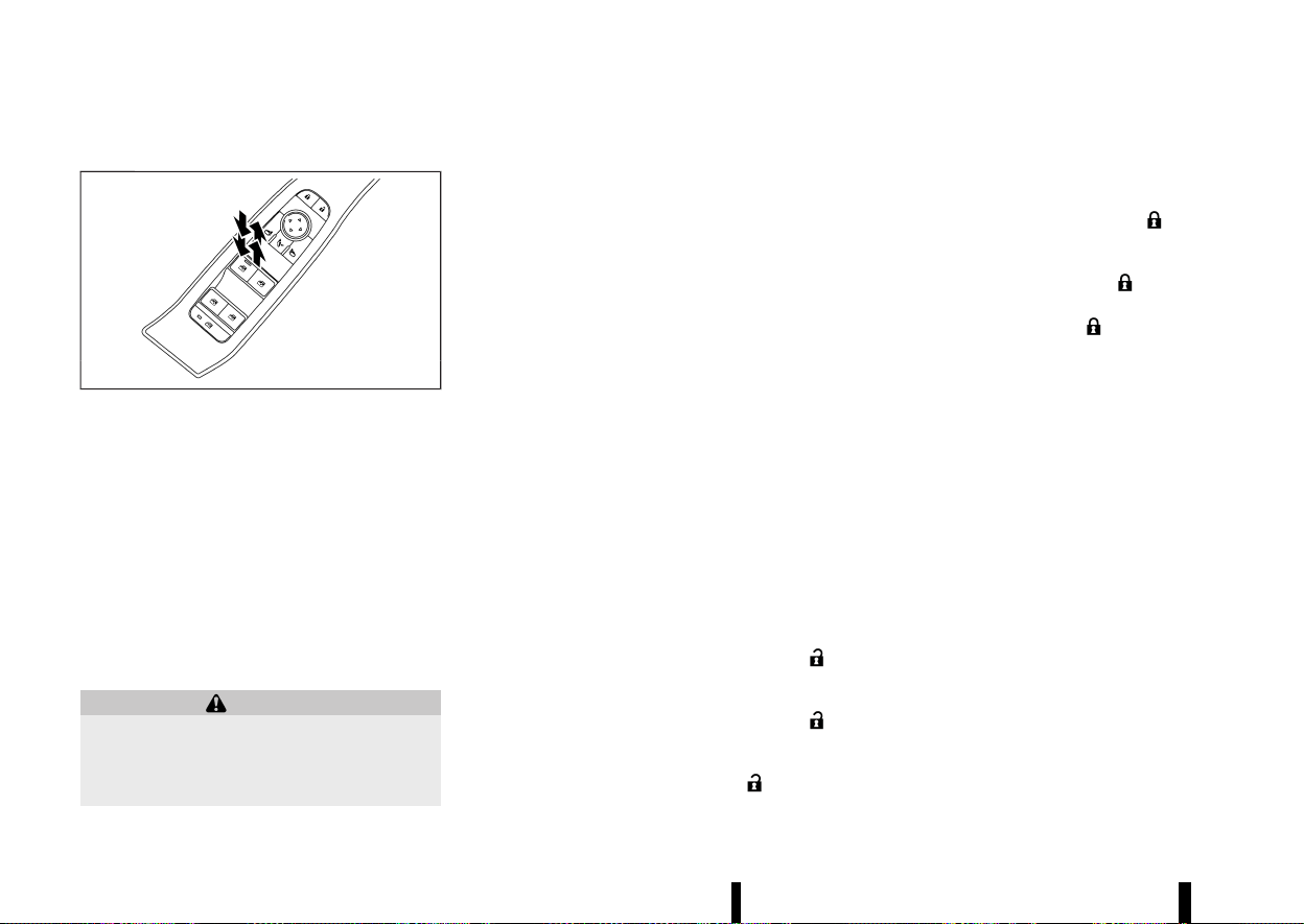
(138,1)
134 Instruments and controls
Automatic function
MEVT33A1-F2AEDE5F-326B-4FB9-9763-AE7CE69B0980
MWAC0756X
The automatic function enables a window to fully
open or close without holding the switch down or
up.
To fully open the window, push the power window
switch down to the second detent and release the
switch. To fully close the window, pull the power
window switch up to the second detent and
release the switch. The switch does not have to
be held during window operation.
To stop the window open/close operation during
the automatic function, push down or pull up the
switch in opposite directions.
Auto-reverse function:
WARNING
There is a small distance just before the closed
position which cannot be detected. Make sure
that all passengers have their hands, etc.
inside the vehicle before closing the windows.
The auto-reverse function enables a window to
automatically reverse when something is caught
in the window as it is closing by the automatic
function. When the control unit detects an ob-
stacle, the window will be lowered immediately.
Depending on the environment or driving condi-
tions, the auto-reverse function may activate if an
impact or load similar to something being caught
in the window occurs.
Window timer:
The window timer allows the window switch to be
operated for a short time even if the ignition
switch is placed in the “OFF” position. The window
timer will be cancelled when the driver’s or front
passenger’s side door is opened or the preset time
has expired.
Operating windows with Intelligent Key
MEVT33A1-EE4722C3-CAE7-4702-B9CE-D4BFAF419106
The windows can be opened or closed by pushing
the “UNLOCK” or LOCK button on the Intelligent
Key. This function will not operate while the
window timer is activated or when the windows
need to be initialised. For details about the
Intelligent Key button usage, see “How to use
remote keyless entry function” (P.154).
Opening:
To open the windows, push the “UNLOCK”
button on the Intelligent Key for about 3 seconds
after the door is unlocked.
To stop opening, release the “UNLOCK”
button.
If the window open operation is stopped on the
way while pushing the “UNLOCK”
button,
release and push the button again until the
windows open completely.
Closing:
To close the windows, push the LOCK
button
on the Intelligent Key for about 3 seconds after the
door is locked.
To stop closing, release the LOCK
button.
If the window close operation is stopped on the
way while pushing the LOCK
button, release
and push the button again until the windows close
completely.
When power window switch does not operate
MEVT33A1-B6340D93-45A3-48B4-BE8B-20DD3A8E0867
If the power window automatic function does not
operate properly, perform the following procedure
to initialise the power window functions.
1. Close the door.
2. Place the ignition switch in the ON position.
3. Pull the power window switch and hold it to
fully close the window.*1
4. Release the power window switch.
5. Pull the power window switch and hold it for
approximately 5 seconds or more.*2
6. Push the power window switch down and hold
it to fully open the window.
7. Release the power window switch.
8. Push the power window switch down and hold
it for approximately 5 seconds or more.*2
9. Pull the power window switch and hold it to
fully close the window.*1
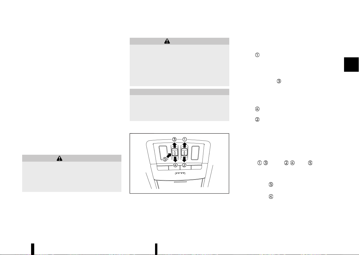
(139,1)
10. Operate the window by the automatic func-
tion (window open and close) to confirm that
the initialisation is complete.
*1: If the window stops before reaching the fully
closed position, release the switch, then pull and
hold it again to fully close the window.
*2: After pulling or pushing the power window
switch and holding it for approximately 5 seconds
or more, the window will move again.
If the window cannot automatically be closed
since the auto-reverse function activated due to
a malfunction, perform the following procedure to
cancel the auto-reverse function.
1. Pull the power window switch up until the
auto-reverse function is activated, then the
window will reverse automatically.
2. Repeat the procedure twice.
3. Pull the power window switch and hold it to
close the window to confirm that the cancella-
tion is completed.
WARNING
When the auto-reverse function is cancelled,
the window will not automatically reverse even
if the control unit detects an obstacle. Make
sure that all passengers have their hands, etc.
inside the vehicle before closing the windows.
If the power window functions do not operate
properly after performing the procedure above,
have your vehicle checked by a NISSAN dealer or
qualified workshop.
MEVT33A1-763E28EB-A953-4A35-A10F-6F137F82E26B
WARNING
* In an accident you could be thrown from
the vehicle through an open sunroof. Al-
ways use seat belts and child restraints.
* Do not allow anyone to stand up or extend
any portion of their body out of the
sunroof opening while the vehicle is in
motion or while the sunroof is closing.
CAUTION
* Remove water drops, snow, ice or sand
from the sunroof before opening.
* Do not place any heavy object on the
sunroof or surrounding area.
AUTOMATIC SUNROOF AND SUNSHADE
MEVT33A1-60D1BFD6-832F-432D-8BEE-8F0AE9FFB2B4
MWAC0759X
Sliding sunshade and sunroof
MEVT33A1-F2AE68AD-35BC-4AA8-83C0-4AA506392BF1
When the sunshade switch is pushed to the OPEN
position
, the sunshade will open. (If the sun-
shade starts to open from the position between
close and half open, the sunshade will stop half.
When the switch is pushed again, the sunshade will
open fully.) When the sunroof switch is pushed to
the OPEN position
, the sunroof opens to the
comfort mode position. (If the sunshade is close,
the sunshade will open half first. When the switch
is pushed again, the sunroof will open fully.)
When the sunroof switch is pushed to the CLOSE
position
, the sunroof will automatically close.
When the sunshade switch is pushed to the CLOSE
position
, the sunshade will close. (If the sun-
shade starts to close from the position between
full and half open, the sunshade will stop half.
When the switch is pushed again, the sunshade will
close fully. However, if the sunroof is open or tilted
up, the sunshade will not close beyond half.)
To stop the sunshade or sunroof during the
operation, push the sunroof switch to either of
the OPEN
, , CLOSE , or UP position.
Tilting sunroof
MEVT33A1-5A375FB1-2459-4E69-B8C9-A8D87A6925A0
To tilt up the sunroof, push the sunroof switch to
the up position
.
To tilt down the sunroof, push the switch to the
CLOSE position
.
Instruments and controls 135
SUNROOF (where fitted)
SUNROOF (where fitted)
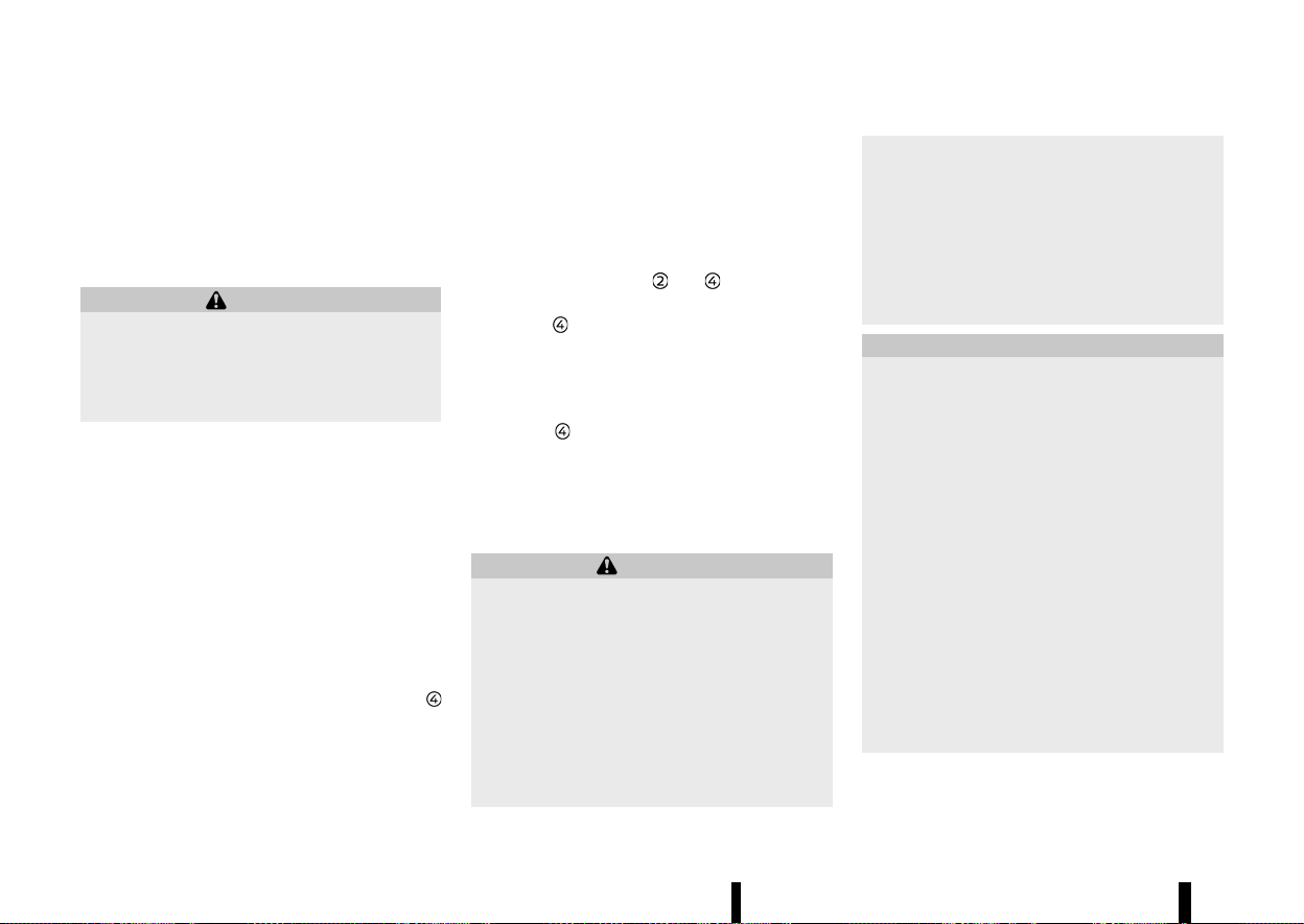
(140,1)
136 Instruments and controls
Comfort mode
MEVT33A1-F85D3D5F-862B-4CED-BA76-75CBE0FDAF74
This is the position used when driving with the
sunroof open. When driving with the sunroof fully
open, wind noise may be very loud. Use the
comfort mode position when driving.
Auto-reverse function
MEVT33A1-05D9BD58-A278-4709-A03A-80DC088F07EC
WARNING
There are some small distances just before the
closed position which cannot be detected.
Make sure that all passengers have their
hands, etc. inside the vehicle before closing
the sunroof and sunshade.
The auto-reverse function enables the sunroof
and sunshade to automatically reverse when
something is caught in the sunroof and sunshade
as it is closing. When the control unit detects an
obstacle, the sunroof and sunshade will open
immediately.
Depending on the environment or driving condi-
tions, the auto-reverse function may activate if an
impact or load similar to something being caught
in the sunroof and sunshade occurs.
If the auto-reverse function activates consecu-
tively or the battery is discharged, the sunroof and
sunshade may not close properly. In this case,
push and hold the switch to the CLOSE position
to close the sunroof.
If the sunroof does not operate
MEVT33A1-375D2428-A2C2-47EB-BFE4-FA7A4BDC9925
If the sunroof and sunshade do not operate
properly, perform the following procedure to
initialise the operation system.
1. If the sunroof and sunshade are open, close
them fully by repeatedly pushing the sunroof
switch to the CLOSE
and position.
2. Push and hold the sunroof switch to the
CLOSE
position for 10 seconds.
3. After the sunroof and sunshade move slightly
to the closed position and then move back a
little, release the sunroof switch.
4. Push and hold the sunroof switch to the
CLOSE
position, and the glass and shade
will move.
5. Release the sunroof switch. Then the sunroof
and sunshade will fully open and then fully
close.
6. Check if the sunroof switch operates normally.
WARNING
The driver is always responsible for operating
the sunroof properly, including the operation
by all passengers. Failure to follow the warn-
ings and instructions for proper use of the
sunroof could result in serious injury or death.
* Do not allow children to operate the
sunroof. Improper operation by children
may cause an accident. If children or
others get caught in the sunroof, it could
cause serious injury.
* To help avoid risk of injury or death
through unintended operation of the sun-
roof, place the ignition switch in the “OFF”
position when leaving the vehicle, and do
not leave children and the Intelligent Key
inside the vehicle.
* Do not activate the auto-reverse function
intentionally. If hands or face, etc. get
caught in the sunroof, it could cause
serious injury.
CAUTION
* Do not place objects (such as newspapers,
handkerchiefs, etc.) on the sunshade when
it is extending or retracting causing im-
proper operation or damage to the sun-
shade.
* Do not push the sunshade arm with your
hands, etc., as this may deform it. Impro-
per operation or damage to the sunshade
may result.
* Do not put any object into the sunshade
inlet port as this may result in improper
operation or damage the sunshade.
* Do not hang any object on the arm rail as
this may result in improper operation or
damage the sunshade.
* Do not forcefully pull the sunshade. Doing
so may elongate the sunshade. Improper
operation or damage to the sunshade may
result.
If the sunroof does not operate properly after
performing the procedure above, have your vehi-
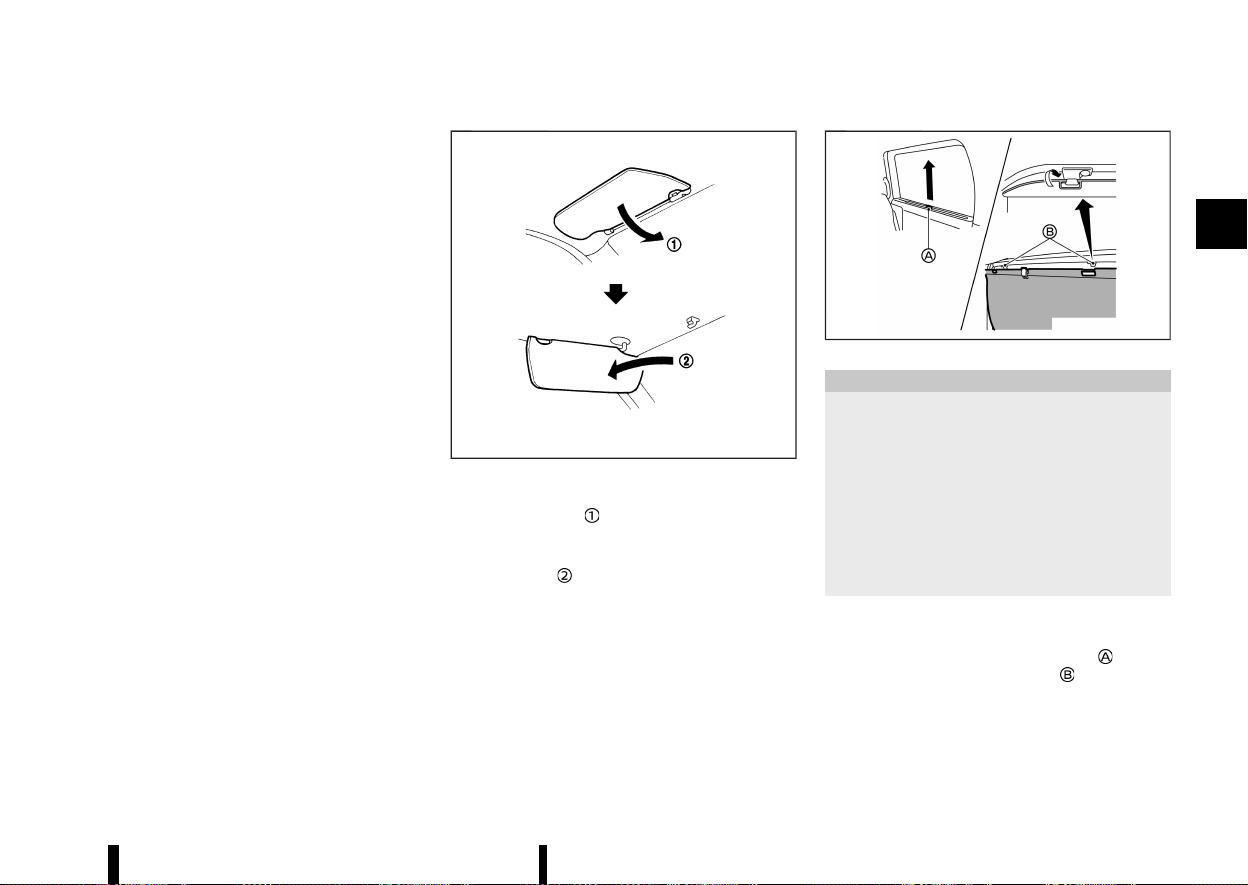
(141,1)
cle checked by a NISSAN dealer or qualified work-
shop.
MEVT33A1-0C588194-A689-4766-88CA-BC25DAECEE47
MSIC2872
1. To block glare from the front, swing down the
main sun visor
.
2. To block glare from the side, remove the main
sun visor from the centre mount and swing it
to the side
.
MEVT33A1-4EA2B96C-4004-43D9-A0D7-6184A011A025
MWAD0237X
CAUTION
* Do not release the rear sunshade during
operation. This could damage the sun-
shade or cause injury.
* Do not forcefully pull the sunshade. Doing
so may elongate the sunshade. This could
cause improper operation or could da-
mage the sunshade.
* Do not place objects on or near the rear
sunshade. This could cause improper op-
eration or could damage the sunshade.
The rear sunshades are equipped on the rear seat
windows.
To raise the sunshade, pull the knob
up and
hang the sunshade on the hooks
.
To store the sunshade, remove the sunshade from
the hooks and lower it.
Instruments and controls 137
SUN VISORS
SUN VISORS
REAR SUNSHADE (where fitted)
REAR SUNSHADE (where fitted)
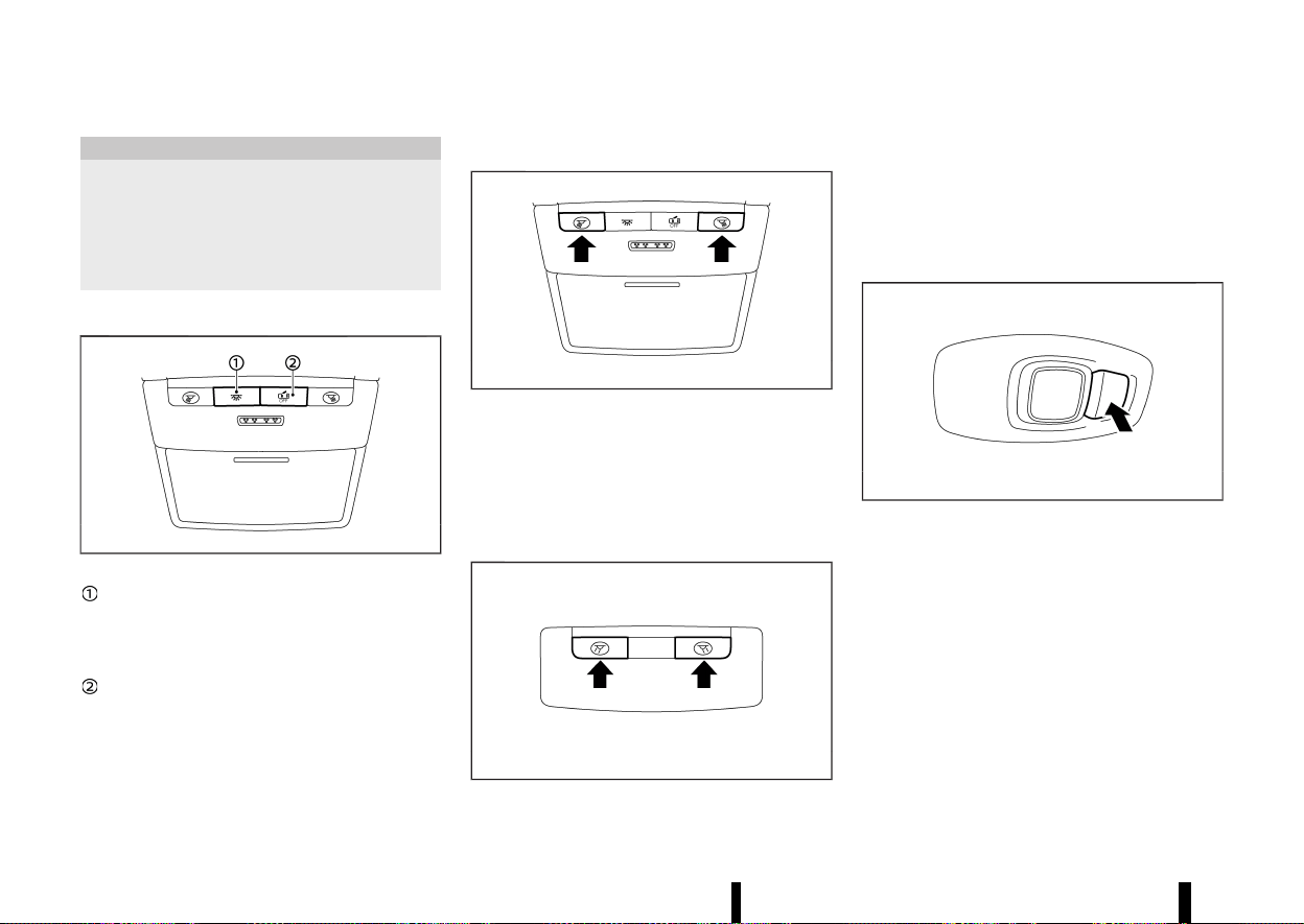
(142,1)
138 Instruments and controls
MEVT33A1-AC8C958B-C3DE-4C13-A406-ED56FDB6824E
CAUTION
* Do not leave the light switch on when the
engine is not running for extended periods
of time to prevent the battery from being
discharged.
* Turn off the lights when you leave the
vehicle.
INTERIOR LIGHT SWITCH
MEVT33A1-E92247E6-514A-49F6-8C49-3DBA37FB2AC2
MWAC0066X
The interior light can be turned ON regard-
less of door position. The light will go off after
a period of time unless the ignition switch is
placed in the ON position when any door is
opened.
The interior lights can be set to operate
when the doors are opened. To turn off the
interior lights when a door is open, push the
switch, the interior lights will not illuminate,
regardless of door position. The lights will go
off when the ignition switch is placed in the
ON position, or the driver’s door is closed and
locked.
MAP LIGHTS
MEVT33A1-1B5DECC4-5E3F-4B04-8666-6F7000099558
MWAC0067X
Push the button to turn the map lights on. To turn
them off, push the button again.
The lights will also turn off after a period of time
when the lights remain illuminated to prevent
the battery from becoming discharged.
ROOM LIGHTS (where fitted)
MEVT33A1-1BA5ED2D-B7A1-4328-B776-B27422235D9C
MWAC0090X
Push the button to turn the room lights on. To turn
them off, push the button again.
The lights will also turn off after a period of time
when the lights remain illuminated to prevent
the battery from becoming discharged.
REAR PERSONAL LIGHTS (where fitted)
MEVT33A1-508E4ED4-61D6-4A70-9A10-CE6690B67E4A
MWAC0509X
To turn the rear personal lights on, push the
button. To turn them off, push the button again.
The lights will also turn off after a period of time
when the lights remain illuminated to prevent
the battery from becoming discharged.
INTERIOR LIGHTS
INTERIOR LIGHTS
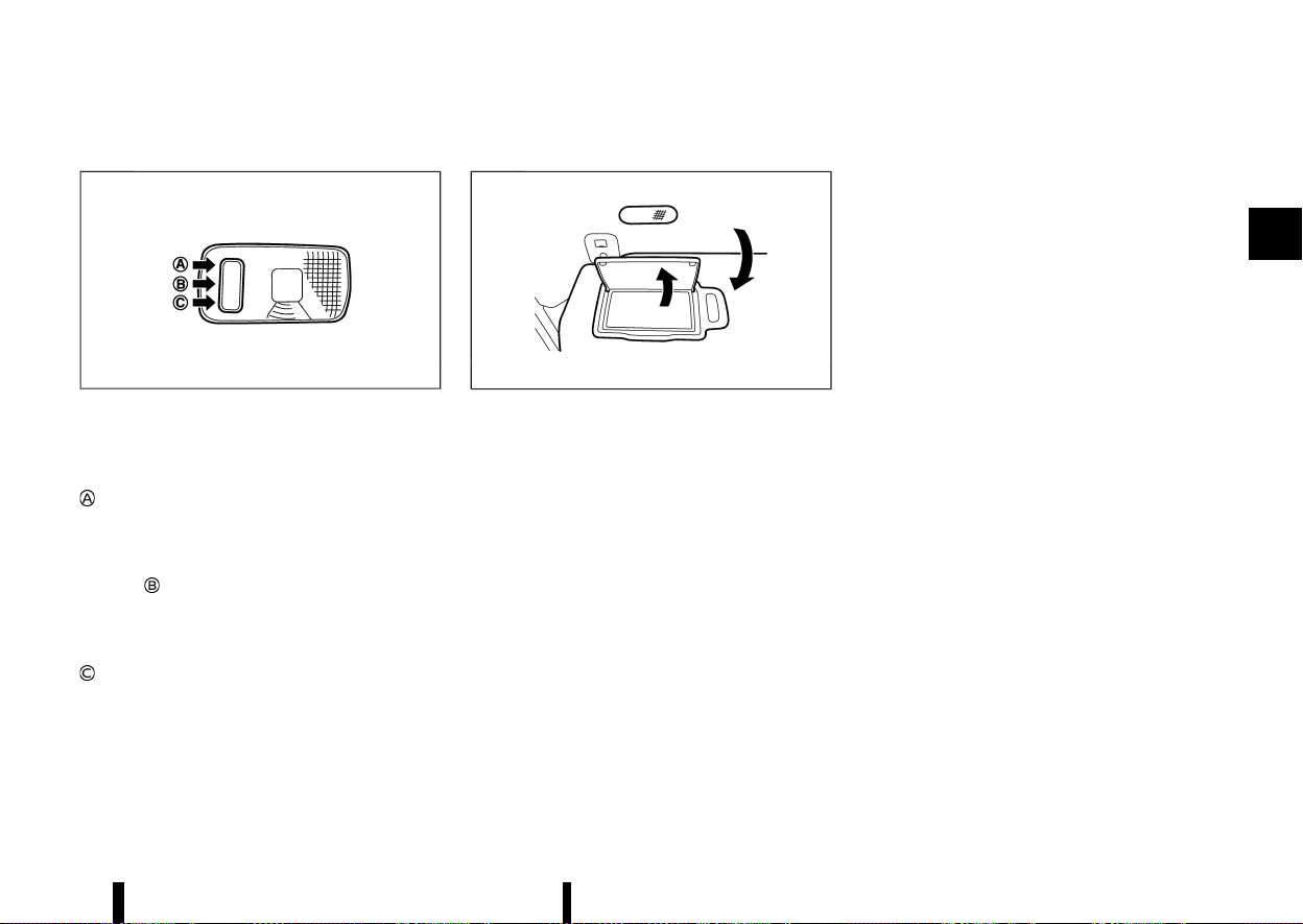
(143,1)
CARGO LIGHT
MEVT33A1-4E7D7193-19FC-43A7-8050-94552D64EF00
MJVI0248X
The cargo light has a three-position switch.
ON position
When the cargo light switch is in the ON position
, the cargo light illuminates, regardless of any
condition.
DOOR position
When the cargo light switch is in the DOOR
position
, the cargo light illuminates when the
back door is opened.
OFF position
When the cargo light switch is in the OFF position
, the cargo light does not illuminate, regardless
of any condition.
The light will also turn off after a period of time
when the light remains illuminated to prevent
the battery from becoming discharged.
VANITY MIRROR LIGHTS (where fitted)
MEVT33A1-1BEB966D-9B4F-4493-95BF-A267E52CAD5C
MWAC0492X
Example
The light over the vanity mirror will turn on when
the cover on the vanity mirror is opened.
When the cover is closed, the light will turn off.
Instruments and controls 139

(144,1)
140 Instruments and controls
MEMO

(145,1)
3 Pre-driving checks and adjustments
Keys ........................................................................................................................ 142
Intelligent Key ...................................................................................... 142
Doors ..................................................................................................................... 143
Super lock system (where fitted) ......................................... 143
Locking with key ................................................................................ 144
Unlocking with inside handle (where fitted) ............... 144
Locking with power door lock switch .............................. 145
Child safety rear door lock ........................................................ 146
Intelligent Key system ............................................................................. 146
Intelligent Key operating range (models with lock
sensor or request switch) .......................................................... 148
Door locks/unlocks precaution (models with lock
sensor or request switch) .......................................................... 148
Intelligent Key operation (models with lock sensor or
request switch) ................................................................................... 148
Battery saver system ..................................................................... 150
Troubleshooting guide ................................................................. 152
How to use remote keyless entry function ................. 154
Hazard indicator operation ....................................................... 156
Security system ............................................................................................ 157
Theft warning system (where fitted) ................................. 157
NISSAN Anti-Theft System (NATS) ........................................ 158
Bonnet .................................................................................................................. 159
Back door .......................................................................................................... 160
Operating manual back door (where fitted) ............... 160
Operating power back door (where fitted) .................. 160
Motion-activated back door (where fitted) .................... 162
Garage mode system (where fitted) .................................... 163
Auto closure (where fitted) .......................................................... 164
Back door release lever .................................................................. 164
Fuel-filler lid ........................................................................................................ 164
Opening the fuel-filler lid .............................................................. 164
How to refuel .......................................................................................... 165
When refuelling from a portable fuel container ......... 166
Steering wheel ................................................................................................. 166
Tilt and telescopic operation ..................................................... 166
Mirrors ................................................................................................................... 167
Inside rearview mirror ..................................................................... 167
Outside rearview mirrors .............................................................. 168
Vanity mirror ........................................................................................... 169
Automatic drive positioner (where fitted) ................................. 169
Memory storage function ............................................................. 169
Entry/Exit function ............................................................................. 170
System operation ................................................................................ 171
Parking brake ................................................................................................... 171
Automatic operation ........................................................................ 171
Manual operation ................................................................................ 172
Automatic brake hold ................................................................................ 173
How to activate/deactivate Automatic brake
hold function .......................................................................................... 174
How to use Automatic brake hold function .................. 174
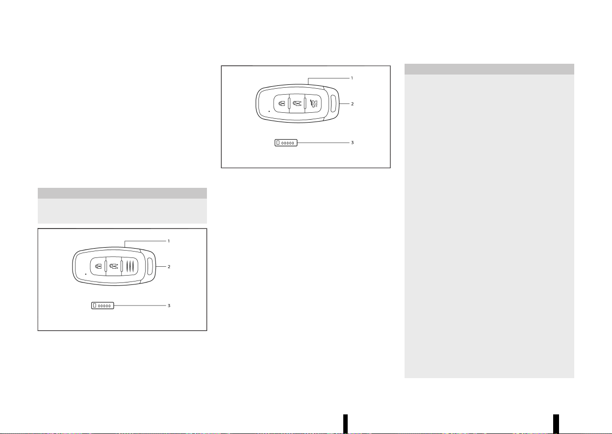
(146,1)
142 Pre-driving checks and adjustments
MEVT33A1-F7866A38-D962-41BD-9D0D-7935A4B2CC6C
Your vehicle can only be driven with the keys
specific to your vehicle. A key number plate is
supplied with your key. Record the key number
and keep the key number plate in a safe place,
except in the vehicle, in case of the need to
duplicate the keys.
The key can only be duplicated using an original
key or the original key number. The key number is
required when you have lost all of the keys and do
not have the original key to duplicate from. If the
key is lost, or you need extra keys, provide an
original key or the key number to a NISSAN dealer
or qualified workshop.
CAUTION
Do not leave the keys inside the vehicle when
leaving the vehicle.
MWBD0014X
Type A
MWBD0015X
Type B
1. Intelligent Key (2)
2. Mechanical key (in the Intelligent Key) (2)
3. Key number plate (1)
INTELLIGENT KEY
MEVT33A1-70B1A049-A959-47AA-AA04-4D59E2864492
Your vehicle can only be driven with the Intelligent
Keys, which are registered to your vehicle’s In-
telligent Key system components and NISSAN Anti-
Theft System (NATS*) components. As many as 4
Intelligent Keys can be registered and used with
one vehicle. The new keys must be registered by a
NISSAN dealer or qualified workshop prior to use
with the Intelligent Key system and NATS of your
vehicle. Since the registration process requires
erasing all memory in the Intelligent Key compo-
nents when registering new keys, be sure to take
all Intelligent Keys that you have to the NISSAN
dealer or qualified workshop.
*: Immobilizer
CAUTION
* Be sure to carry the Intelligent Key with
you. Do not leave the vehicle with the
Intelligent Key inside.
* Be sure to carry the Intelligent Key with
you when driving. The Intelligent Key is a
precision device with a built-in transmitter.
To avoid damaging it, please note the
following.
— The Intelligent Key is water resistant;
however, wetting may damage the
Intelligent Key. If the Intelligent Key
gets wet, immediately wipe until it is
completely dry.
— Do not bend, drop or strike it against
another object.
— If the outside temperature is below
−10°C (14°F) degrees, the battery of the
Intelligent Key may not function prop-
erly.
— Do not place the Intelligent Key for an
extended period in a place where
temperatures exceed 60°C (140°F).
— Do not change or modify the Intelli-
gent Key.
— Do not use a magnet key holder.
— Do not place the Intelligent Key near
an electric appliance such as a televi-
sion set, personal computer or mobile
phone.
— Do not allow the Intelligent Key to
come into contact with water or salt
KEYS
KEYS
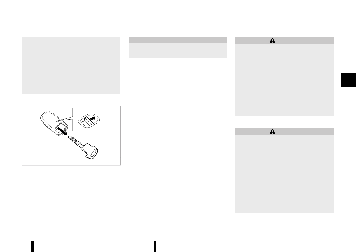
(147,1)
water, and do not wash it in a washing
machine. This could affect the system
function.
* If an Intelligent Key is lost or stolen, NISSAN
recommends erasing the ID code of that
Intelligent Key. This will prevent the Intel-
ligent Key from unauthorised use to unlock
the vehicle. For information regarding the
erasing procedure, please contact a
NISSAN dealer or qualified workshop
Mechanical key
MEVT33A1-EED60269-A431-4073-A19B-5A82DD409AD0
MWBD0016X
To remove the mechanical key, release the lock
knob at the back of the Intelligent Key.
To install the mechanical key, firmly insert it into
the Intelligent Key until the lock knob returns to
the lock position.
Use the mechanical key to lock or unlock the
driver’s door. (See “Doors” (P.143).)
CAUTION
Always carry the mechanical key installed in
the Intelligent Key.
MEVT33A1-A67171A1-8A0F-4CD6-B876-B41D1675EF9C
WARNING
* Before opening any door, always look for
and avoid oncoming traffic.
* To help avoid risk of injury or death
through unintended operation of the ve-
hicle and or its systems, including entrap-
ment in windows or inadvertent door lock
activation, do not leave children, people
who require the assistance of others or
pets unattended in your vehicle. Addition-
ally, the temperature inside a closed vehi-
cle on a warm day can quickly become
high enough to cause a significant risk of
injury or death to people and pets.
SUPER LOCK SYSTEM (where fitted)
MEVT33A1-66AFF87D-AC59-4051-8D46-72695ACC60B7
WARNING
For Super Lock system equipped models, fail-
ure to follow the precautions below may lead
to hazardous situations. Make sure the Super
Lock system activation is always safely con-
ducted.
* When the vehicle is occupied, never lock
the doors with the Intelligent Key. Doing so
will trap the occupants, since the Super
Lock system prevents the doors from
being opened from the inside of the
vehicle.
* Only operate the Intelligent Key lock but-
ton when there is a clear view of the
vehicle. This is to prevent anybody from
Pre-driving checks and adjustments 143
DOORS
DOORS
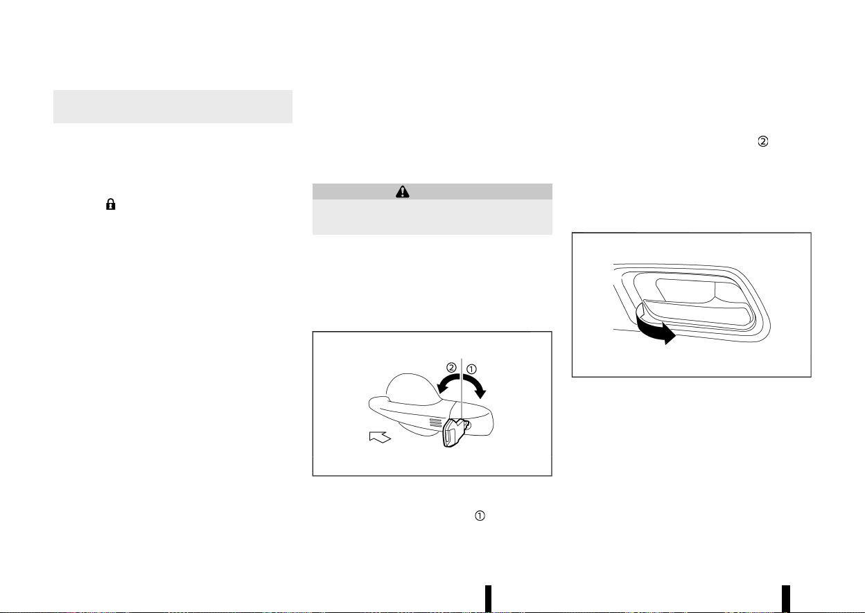
(148,1)
144 Pre-driving checks and adjustments
being trapped inside the vehicle through
the Super Lock system activation.
Locking the doors with the Intelligent Key or the
lock sensor (on the front door handles - where
fitted) will lock all doors including the back door
and activate the Super Lock system.
To activate the Super Lock system, double-press
the LOCK
button on the Intelligent Key or lock
the doors by double-pressing the lock sensor.
Hazard indicator lights flash longer to indicate
Super Lock activation.
This means that none of the doors can be opened
from the inside in order to prevent theft.
The system will be released when the door is
unlocked with the Intelligent Key or the capacitive
unlock sensor (on the front door handles - where
fitted).
The Super Lock system will not activate when the
doors are locked with the power door lock switch.
Emergency situations
MEVT33A1-356D722C-13D6-44A7-A362-3E40B0469BBD
If the Super Lock system is activated due to a
traffic accident or other unexpected circum-
stances while you are in the vehicle:
* Place the ignition switch in the ON position,
the Super Lock system will be released and all
the doors can be unlocked with the power
door lock switch. You can then open the doors.
* Unlock the door using the Intelligent Key. The
Super Lock system will be released and you
can open the door.
* Open or break the driver’s door window and
then insert the key into the outside door key
cylinder and turn it towards the rear of the
vehicle. The driver’s door will unlock and can
be opened from inside the vehicle.
Locking without activating the Super Lock system
MEVT33A1-F3C0501B-0E70-406E-9D9B-ADDF6894DAE9
WARNING
Do not leave the key inside the vehicle when
leaving the vehicle.
Locking the doors using the door key cylinder, or
by a single press of the LOCK button on the
Intelligent Key, or by a single press of lock sensor
(where fitted) will not activate the Super Lock
system.
LOCKING WITH KEY
MEVT33A1-09541342-6724-4CE2-895E-4D3E3867B102
MWBD0017X
To lock the driver’s door, turn the driver’s door key
cylinder to the rear of the vehicle
.
Locking the driver’s door will simultaneously lock
all doors.
To unlock the driver’s door, turn the driver’s door
key cylinder to the front of the vehicle
.
You can also lock or unlock the other doors and
the back door by using the Intelligent Key function.
(See “Intelligent Key system” (P.146).)
UNLOCKING WITH INSIDE HANDLE
(where fitted)
MEVT33A1-67CE94FD-F542-452E-BA5B-04DB4EEBEE83
MWAD0367X
To unlock and open the door, pull the inside door
handle as illustrated.
To switch the door unlock mode from one to
another, push and hold the "LOCK" and "UNLOCK"
button on the Intelligent Key or see “[Vehicle
Settings]” (P.86).
* Selective door unlock mode
Only the corresponding door will be unlocked.
* All door unlock mode
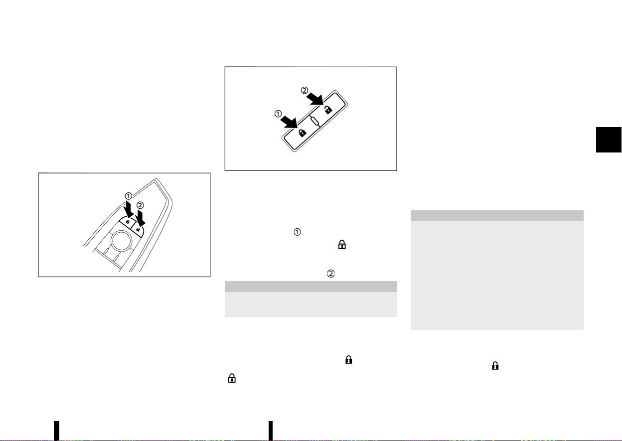
(149,1)
— Front inside door handle:
All doors will be unlocked.
— Rear inside door handle:
Only the corresponding door will be un-
locked.
The doors cannot be opened by using the inside
door handle when the Super Lock system (where
fitted) is activated.
LOCKING WITH POWER DOOR LOCK
SWITCH
MEVT33A1-5256BBAD-C319-43C6-9C66-55957ADC778F
MWAD0239X
Driver’s armrest
MWAD0240X
Front passenger’s armrest
Operating the power door lock switch (located on
the driver’s and front passenger’s doors) will lock
or unlock all the doors.
To lock the doors, push the power door lock switch
to the lock position
.
The door lock indicator light
on the roof
console comes on when the doors are locked.
To unlock the doors, push the power door lock
switch to the unlock position
.
CAUTION
Never leave the Intelligent Key in the vehicle
when you leave the vehicle.
NOTE:
Models without the Super Lock system: If a door
is manually opened from inside after having
pressed the Intelligent Key LOCK
button, the
door will unlock and the door lock indicator light
goes out.
Lockout protection
MEVT33A1-44F7A60E-83C3-4161-B6E9-F0CE6E62B151
Lockout protection function helps to prevent the
keys from being accidentally locked inside the
vehicle.
When the power door lock switch is pushed to the
lock position with any door open, all doors will not
lock automatically and a chime will sound after the
door is closed.
NOTE:
The doors may not lock when the Intelligent Key
is in the same hand that is operating the lock
sensor (where fitted) to lock the door. Put the
Intelligent Key in a purse, pocket or your other
hand.
CAUTION
The lockout protection may not function under
the following conditions:
* When the Intelligent Key is placed on top of
the instrument panel.
* When the Intelligent Key is placed inside
the glove box or a storage bin.
* When the Intelligent Key is placed inside
the door pockets.
* When the Intelligent Key is placed inside or
near metallic materials.
Super Lock equipped models (RHD models)
MEVT33A1-A399933D-EC06-4F63-AF17-6CA9EB4222EC
If the doors are locked by double-pressing the
Intelligent Key LOCK
button or by double-
pressing a lock sensor (where fitted), the Super
Lock system will be activated. The door lock
Pre-driving checks and adjustments 145

(150,1)
146 Pre-driving checks and adjustments
indicator light on the roof console comes on
to indicate that all doors are locked, but it will not
be possible to use the UNLOCK button of the
power door lock switch to unlock the doors.
Locking the doors with the power door lock switch
will not activate the Super Lock system.
CHILD SAFETY REAR DOOR LOCK
MEVT33A1-23BE1446-C8BC-4A11-8767-2B460D5530B1
MWAD0021X
Child safety rear door locks help prevent the rear
doors from being opened accidentally, especially
when small children are in the vehicle.
When the levers are in the lock position
, the
rear doors can be opened only from the outside.
To disengage, move the levers to the unlock
position
.
MEVT33A1-469FCA8B-4CA7-4AE5-9396-44D8FD1027E9
MWBD0014X
Type A
MWBD0015X
Type B
1. Intelligent Key (2)
2. Mechanical key (in the Intelligent Key) (2)
3. Key number plate (1)
WARNING
* Radio waves could adversely affect electric
medical equipment. Those who use a
pacemaker should contact the electric
medical equipment manufacturer for the
possible influences before use.
* The Intelligent Key transmits radio waves
when the buttons are pushed. The radio
waves may affect aircraft navigation and
communication systems. Do not operate
the Intelligent Key while on an aeroplane.
Make sure the buttons are not operated
unintentionally when the unit is stored
during a flight.
The Intelligent Key system can operate all the door
locks using the integrated key fob function,
touching lock or capacitive unlock sensor (where
fitted) or pushing the request switch (where fitted)
on the vehicle without taking the key out from a
pocket or purse. The operating environment and/
or conditions may affect the Intelligent Key system
operation.
Be sure to read the following before using the
Intelligent Key system.
CAUTION
* Be sure to carry the Intelligent Key with
you when operating the vehicle.
* Never leave the Intelligent Key in the
vehicle when you leave the vehicle.
The Intelligent Key is always communicating with
the vehicle as it receives radio waves. The Intelli-
gent Key system transmits weak radio waves.
Environmental conditions may interfere with the
operation of the Intelligent Key system under the
following operating conditions.
INTELLIGENT KEY SYSTEM
INTELLIGENT KEY SYSTEM

(151,1)
* When operating near a location where strong
radio waves are transmitted, such as a TV
tower, power station and broadcasting sta-
tion.
* When in possession of wireless equipment,
such as a mobile phone, transceiver, and CB
radio.
* When the Intelligent Key is in contact with or
covered by metallic materials.
* When any type of radio wave remote control is
used nearby.
* When the Intelligent Key is placed near an
electric appliance such as a personal compu-
ter.
* When the vehicle is parked near a parking
meter.
In such cases, correct the operating conditions
before using the Intelligent Key function or use the
mechanical key.
Although the life of the battery varies depending
on the operating conditions, the battery’s life is
approximately 2 years. If the battery is discharged,
replace it with a new one.
When the Intelligent Key battery is low, an indicator
illuminates in the vehicle information display. (See
“4. [Key Battery Low] warning” (P.93).)
Since the Intelligent Key is continuously receiving
radio waves, if the key is left near equipment which
transmits strong radio waves, such as signals from
a TV and personal computer, the battery life may
become shorter.
For information regarding replacement of a bat-
tery, see “Intelligent Key battery” (P.439).
As many as 4 Intelligent Keys can be registered
and used with one vehicle. For information about
the purchase and use of additional Intelligent Keys,
it is recommended that you contact a NISSAN
dealer or qualified workshop.
CAUTION
* Do not allow the Intelligent Key, which
contains electrical components, to come
into contact with water or salt water. This
could affect the system function.
* Do not drop the Intelligent Key.
* Do not strike the Intelligent Key sharply
against another object.
* Do not change or modify the Intelligent
Key.
* Wetting may damage the Intelligent Key. If
the Intelligent Key gets wet, immediately
wipe until it is completely dry.
* If the outside temperature is below −10°C
(14°F) degrees, the battery of the Intelligent
Key may not function properly.
* Do not place the Intelligent Key for an
extended period in an area where tem-
peratures exceed 60°C (140°F).
* Do not attach the Intelligent Key with a key
holder that contains a magnet.
* Do not place the Intelligent Key near
equipment that produces a magnetic field,
such as a TV, audio equipment, personal
computers, mobile phone or wireless char-
ger.
If an Intelligent Key is lost or stolen, NISSAN
recommends erasing the ID code of that Intelligent
Key from the vehicle. This may prevent the
unauthorised use of the Intelligent Key to operate
the vehicle. For information regarding the erasing
procedure, it is recommended that you contact a
NISSAN dealer or qualified workshop.
For models with lock sensor: The Intelligent Key
function can be disabled. For information about
disabling the Intelligent Key function, it is recom-
mended that you contact a NISSAN dealer or
qualified workshop.
Pre-driving checks and adjustments 147
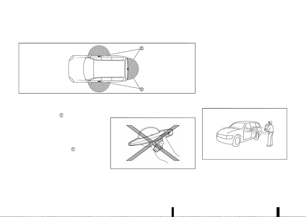
(152,1)
148 Pre-driving checks and adjustments
INTELLIGENT KEY OPERATING RANGE (models with lock sensor or request switch)
MEVT33A1-91774517-D9C2-4D6B-B56E-0CB1563C54AD
MSPA2074
The Intelligent Key functions can only be used
when the Intelligent Key is within the specified
operating range from the lock or capacitive unlock
sensors/request switch
.
When the Intelligent Key battery is discharged or
strong radio waves are present near the operating
location, the Intelligent Key system’s operating
range becomes narrower, and the Intelligent Key
may not function properly.
The operating range is within 80 cm (31.50 in) from
each sensor or request switch
.
If the Intelligent Key is too close to the door glass,
handle or rear bumper, the sensors or the request
switch may not function.
When the Intelligent Key is within the operating
range, it is possible for anyone who does not carry
the Intelligent Key to use the lock or capacitive
unlock sensors or request switch to lock/unlock
the doors including the back door.
DOOR LOCKS/UNLOCKS PRECAUTION
(models with lock sensor or request
switch)
MEVT33A1-A4BC8E7F-38FC-4B38-9CDF-60990152CE23
MWBD0035X
* Do not use the lock or capacitive unlock
sensors or request switch with the Intelligent
Key held in your hand as illustrated. The close
distance to the door handle will cause the
Intelligent Key system to have difficulty recog-
nising that the Intelligent Key is outside the
vehicle.
* After locking with the lock sensors or the
request switch, verify the doors are securely
locked by testing them.
* To prevent the Intelligent Key from being left
inside the vehicle, make sure you carry the key
with you and then lock the doors.
* Do not pull the door handle before unlocking it
by the capacitive unlock sensor or the request
switch.
INTELLIGENT KEY OPERATION (models
with lock sensor or request switch)
MEVT33A1-6456B930-7647-4AFE-BD16-B7ABE41384AC
MSPA2408
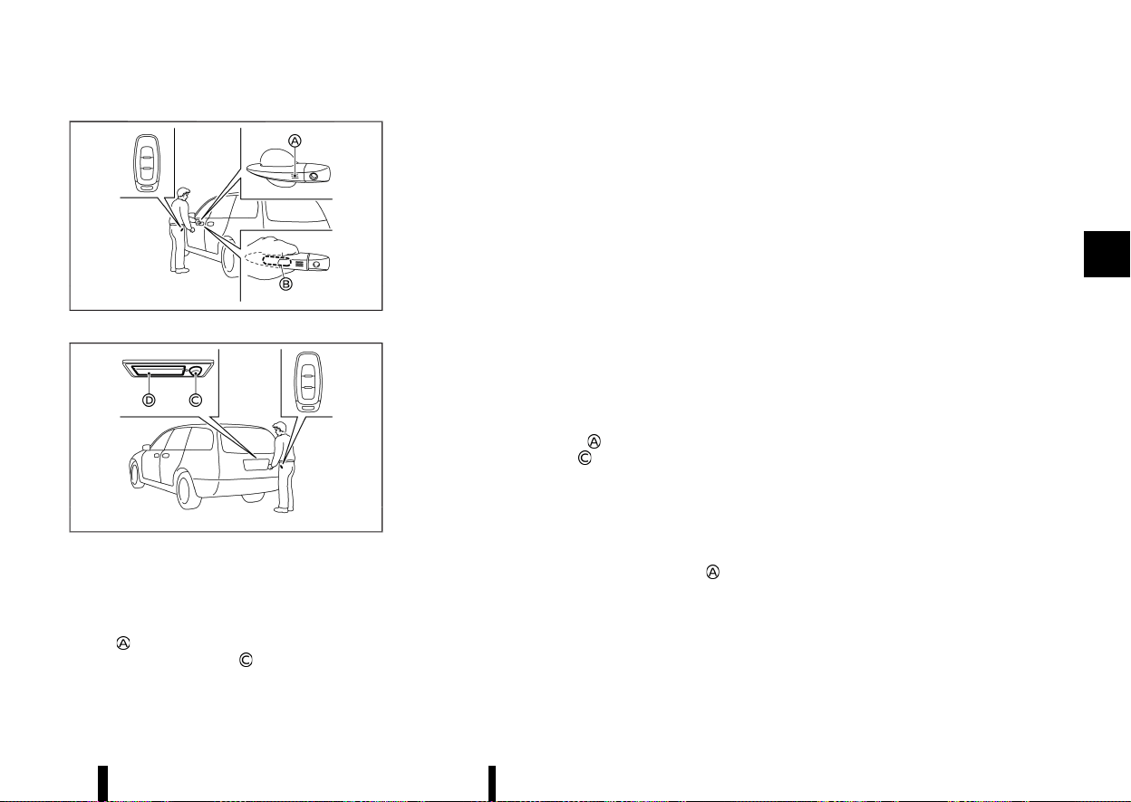
(153,1)
MWBD0034X
Example
MWBD0036X
Example
You can lock or unlock the doors without taking
the key out from your pocket or bag.
When you carry the Intelligent Key with you, you
can lock or unlock all doors by using the lock
sensor
(located on the front door handles) or
back door request switch
within the range of
operation.
When you lock or unlock the doors, the hazard
indicator will flash as a confirmation. For details,
see “Hazard indicator operation” (P.156).
Welcome light and farewell light function
MEVT33A1-D0F7A970-B7BB-47FC-A02D-47523A2633F4
When you lock or unlock the doors or the back
door, the clearance lights and the tail lights will
illuminate for a period of time. The welcome light
and farewell light function can be disabled. For
information about disabling the welcome light and
farewell light function, see “[Vehicle Settings]”
(P.86).
Locking doors
MEVT33A1-FBCFDD0D-7E86-418A-8AC6-81E178864EEE
1. Push the park button to engage the P (Park)
position. Place the ignition switch in the “OFF”
position and make sure you carry the Intelli-
gent Key with you.
2. Close all doors.
3. Touch the lock sensor
or push the back
door request switch
while carrying the
Intelligent Key with you.
4. All doors and the back door will lock. The
hazard indicator lights flash once.
For models with the Super Lock system:
To activate the Super Lock system, lock the
doors by double-pressing the lock sensor
.
The hazard indicator lights flash longer to
indicate Super Lock system activation.
NOTE:
* Lock sensors for all doors can be deacti-
vated when the “I-Key Door Lock” is turned
off in the Vehicle Setting of the vehicle
information display. For additional informa-
tion, see “[Vehicle Settings]” (P.86).
* Doors lock with the lock sensor or back door
request switch while the ignition switch is
not in the “OFF” position.
* Doors do not lock by touching the driver’s
door lock sensor while the driver’s door is
open. However, doors lock with the mechan-
ical key even if any door is open.
* Doors do not lock with the lock sensor or
back door request switch with the Intelligent
Key inside the vehicle and a beep sounds to
warn you. However, when an Intelligent Key
is inside the vehicle, doors can be locked
with another Intelligent Key.
* Doors do not lock with the lock sensor while
the engine is running.
* If the door handle becomes wet while the
Intelligent Key is within the effective range,
the door may lock and unlock repeatedly. In
this case, follow the following correction
procedures to wash the vehicle:
— Place the Intelligent Key in a location 2 m
(6 ft) or more away from the vehicle. (Take
care to ensure that the key is not stolen.)
— If the Intelligent Key is inside the vehicle
and a door handle becomes wet during a
car wash, a buzzer will sound outside the
vehicle. To turn off the alarm, take the
Intelligent Key from inside the vehicle.
* The lock sensor may not work properly if it
comes in contact with ice, snow, mud, etc.
Clean the lock sensor and attempt to oper-
ate it again.
Pre-driving checks and adjustments 149
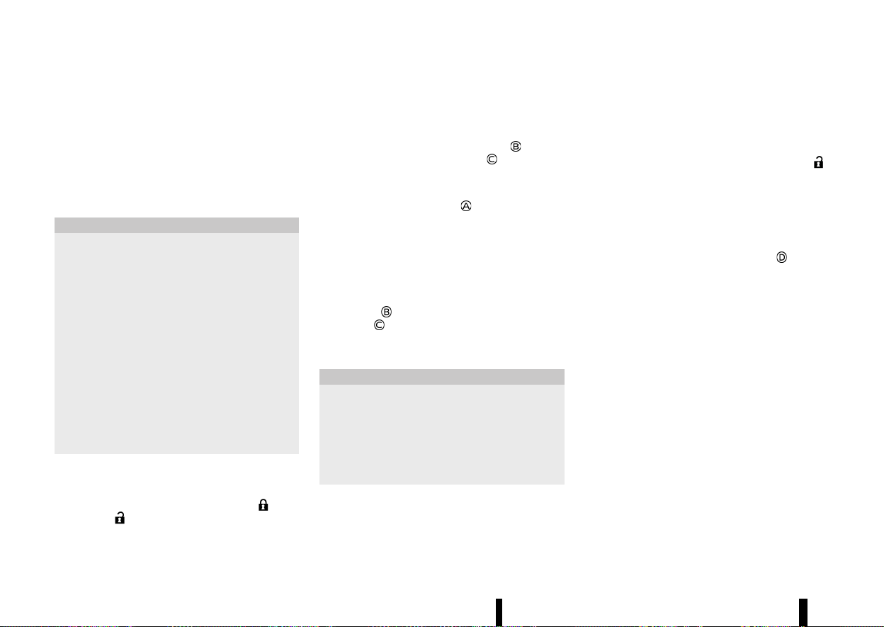
(154,1)
150 Pre-driving checks and adjustments
* If the door handle becomes wet, such as
rain, the door may delay or prevent lock
operation. In this case, try to touch firmly the
sensor for at least 1 second.
* The lock sensor may not react immediately
when the door handle gets wet from rain,
etc. Keep touching the lock sensor until the
doors lock, or touch the lock sensor after
grasping the door handle.
CAUTION
* After locking the doors using the lock
sensor or back door request switch, make
sure that the doors have been securely
locked by operating the door handles or
the back door opener switch.
* When locking the doors using the lock
sensor or back door request switch, make
sure to have the Intelligent Key in your
possession before operating the lock sen-
sor or back door request switch to prevent
the Intelligent Key from being left in the
vehicle.
* The lock sensor or back door request
switch is operational only when the Intel-
ligent Key has been detected by the
Intelligent Key system.
Unlocking doors
MEVT33A1-7D2E138F-DB95-4FC9-B4BF-88DB18ADEF5F
To switch the door unlock mode from one to
another, push and hold the "LOCK"
and
"UNLOCK"
button on the Intelligent Key or
see “[Vehicle Settings]” (P.86).
Selective door unlock mode:
1. Carry the Intelligent Key with you.
2. Wrap the driver’s or front passenger’s door
handle (capacitive unlock sensor)
or push
the back door request switch
.
3. Only the corresponding door will be unlocked.
The hazard indicator lights flash twice quickly.
4. Touch the lock sensor
within 5 seconds
after releasing the door handle.
5. All doors will be unlocked. The hazard indica-
tor lights flash twice slowly.
All door unlock mode:
1. Carry the Intelligent Key with you.
2. Wrap the front door handle (capacitive unlock
sensor)
or push the back door request
switch
.
3. All doors will be unlocked.
4. Operate the door handles to open the doors.
CAUTION
If a door handle is pulled while unlocking the
doors, that door may not be unlocked. Return-
ing the door handle to its original position will
unlock the door. If the door does not unlock,
after returning the door handle, touch the
capacitive unlock sensor or push the request
switch to unlock the door.
Automatic relock:
All doors will be locked automatically unless one of
the following operations is performed within 30
seconds after touching the capacitive unlock
sensor or pushing the request switch while the
doors are locked.
* Opening any doors.
* Pushing the ignition switch.
If during the preset time period, the “UNLOCK”
button on the Intelligent Key is pushed, all doors
will be locked automatically after another 30
seconds.
Opening back door
MEVT33A1-831C2138-5229-4F3F-B568-8B9686722EC1
1. Carry the Intelligent Key.
2. Push the back door opener switch
.
3. The back door will unlock and then open.
BATTERY SAVER SYSTEM
MEVT33A1-817AD6BA-79E5-43BC-A0CC-216A5D867A2A
When all the following conditions are met for a
period of time, the battery saver system will cut off
the power supply to prevent battery discharge.
* The ignition switch is in the ON position. (See
“Push-button ignition switch positions”
(P.245).)
Warning lights and audible reminders
MEVT33A1-9651A744-FFA0-4CDB-B228-1C2F7BB0B640
To help prevent the vehicle from moving unex-
pectedly by erroneous operation of the Intelligent
Key listed on the following chart or to help prevent
the vehicle from being stolen, chime or beep
sounds inside and outside the vehicle and the
warning display appears on the vehicle informa-
tion display.
When a chime or beep sounds or the warning
display appears, be sure to check the vehicle and
Intelligent Key.


(156,1)
152 Pre-driving checks and adjustments
TROUBLESHOOTING GUIDE
MEVT33A1-FD003181-723A-472E-84F6-40154676082B
Symptom Possible cause
Action to take
When stopping the engine
The [Shift to Park] warning appears on the
display and the inside warning chime sounds
continuously.
The shift position is not in the P (Park)
position.
Push the park button to engage the P (Park)
position.
[Press and Hold to Stop Engine] message
appears on the display.
The Intelligent Key is not inside the
vehicle.
Carry the Intelligent Key inside the vehicle
and push the ignition switch once to stop
the engine.
There is not the Intelligent Key or the
battery charge is low.
Rapidly push the ignition switch 3 conse-
cutive times or push and hold the ignition
switch for more than 2 seconds to stop the
engine.
When opening the driver’s door to
get out of the vehicle
The door/back door open warning appears on
the display.
The ignition switch is in the ON position.
Place the ignition switch in the “OFF” posi-
tion.
When closing the door after get-
ting out of the vehicle
The [No key detected] warning appears on the
display, the outside chime sounds three times
and the inside warning chime sounds for
approximately 3 seconds.
The engine is running.
Place the ignition switch in the “OFF” posi-
tion.
The Rear Door Alert (where fitted) warning
message appears on the display, the horn
sounds three times, pauses, and sounds three
more times, or a Check Rear Seat warning
appears on the display.
The Rear Door Alert (where fitted) is
activated.
Check the rear seat for all articles, clear the
Rear Door Alert warning message by using
the steering switches.
When touching the lock sensor
(where fitted) or pushing the back
door request switch (where fitted)
to lock doors
The outside chime sounds for approximately 3
seconds.
The Intelligent Key is inside the vehicle.
Carry the Intelligent Key with you.
When pushing the ignition switch
to start the engine
The [Key Battery Low] warning appears on the
display.
The Intelligent Key battery charge is low.
Replace the battery with a new one. (See
“Intelligent Key battery” (P.439).)
When pushing the ignition switch
The [Key System Fault] warning appears on the
display.
It warns of a malfunction with the
Intelligent Key system.
It is recommended that you contact a
NISSAN dealer or qualified workshop.

(157,1)
Symptom Possible cause
Action to take
When stopping the engine
The [Shift to Park] warning appears on
the display and the inside warning
chime sounds continuously.
The shift position is not in the P
(Park) position.
Push the park button to engage the
P (Park) position.
[Press and Hold to Stop Engine] mes-
sage appears on the display.
The Intelligent Key is not inside
the vehicle.
Carry the Intelligent Key inside the
vehicle and push the ignition switch
once to stop the engine.
There is not the Intelligent Key or
the battery charge is low.
Rapidly push the ignition switch 3
consecutive times or push and hold
the ignition switch for more than 2
seconds to stop the engine.
When opening the driver’s
door to get out of the
vehicle
The door/back door open warning
appears on the display.
The ignition switch is in the ON
position.
Place the ignition switch in the
“OFF” position.
When closing the door after
getting out of the vehicle
The [No key detected] warning ap-
pears on the display, the outside
chime sounds three times and the
inside warning chime sounds for ap-
proximately 3 seconds.
The engine is running.
Place the ignition switch in the
“OFF” position.
When touching the lock
sensor (where fitted) or
pushing the back door re-
quest switch (where fitted)
to lock doors
The outside chime sounds for ap-
proximately 3 seconds.
The Intelligent Key is inside the
vehicle.
Carry the Intelligent Key with you.
When pushing the ignition
switch to start the engine
The [Key Battery Low] warning ap-
pears on the display.
The Intelligent Key battery
charge is low.
Replace the battery with a new one.
(See “Intelligent Key battery”
(P.439).)
When pushing the ignition
switch
The [Key System Fault] warning ap-
pears on the display.
It warns of a malfunction with
the Intelligent Key system.
It is recommended that you contact
a NISSAN dealer or qualified work-
shop.
Pre-driving checks and adjustments 153
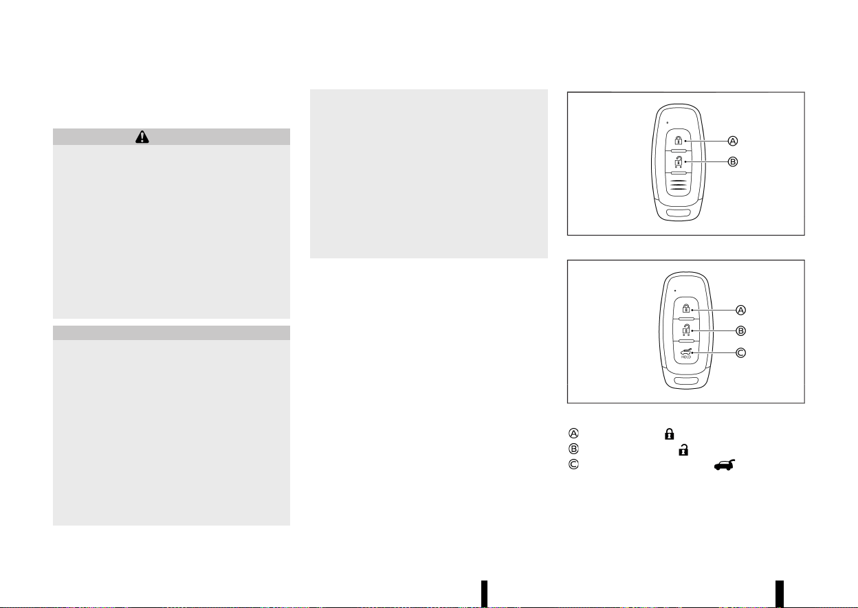
(158,1)
154 Pre-driving checks and adjustments
HOW TO USE REMOTE KEYLESS ENTRY
FUNCTION
MEVT33A1-CF76A4ED-43D7-44C7-A605-BA799B1A10EE
WARNING
* Radio waves could adversely affect electric
medical equipment. Those who use a
pacemaker should contact the electric
medical equipment manufacturer for the
possible influences before use.
* The Intelligent Key transmits radio waves
when the buttons are pushed. The radio
waves may affect aircraft navigation and
communication systems. Do not operate
the Intelligent Key while on an aeroplane.
Make sure the buttons are not operated
unintentionally when the unit is stored
during a flight.
CAUTION
* Do not allow the Intelligent Key, which
contains electrical components, to come
into contact with water or salt water. This
could affect the system function.
* Do not drop the Intelligent Key.
* Do not strike the Intelligent Key sharply
against another object.
* Do not change or modify the Intelligent
Key.
* Wetting may damage the Intelligent Key. If
the Intelligent Key gets wet, immediately
wipe until it is completely dry.
* If the outside temperature is below −10°C
(14°F) degrees, the battery of the Intelligent
Key may not function properly.
* Do not place the Intelligent Key for an
extended period in an area where tem-
peratures exceed 60°C (140°F).
* Do not attach the Intelligent Key with a key
holder that contains a magnet.
* Do not place the Intelligent Key near
equipment that produces a magnetic field,
such as a TV, audio equipment, personal
computers, mobile phone or wireless char-
ger.
The remote keyless entry function can operate all
door locks using the remote keyless entry function
of the Intelligent Key. The remote keyless entry
function can operate at a distance of approxi-
mately 1 m (3.3 ft) from the vehicle. (The operating
distance depends upon the conditions around the
vehicle.)
The remote keyless entry function will not operate:
* When the Intelligent Key is not within the
operational range.
* When the Intelligent Key battery is discharged.
The remote keyless entry function can also oper-
ate the vehicle alarm.
MWBD0020X
Type A
MWBD0021X
Type B
LOCK button
UNLOCK button
Power back door button
When you lock or unlock the doors or the back
door, the hazard indicator will flash as a confirma-
tion. For details, see “Hazard indicator operation”
(P.156).
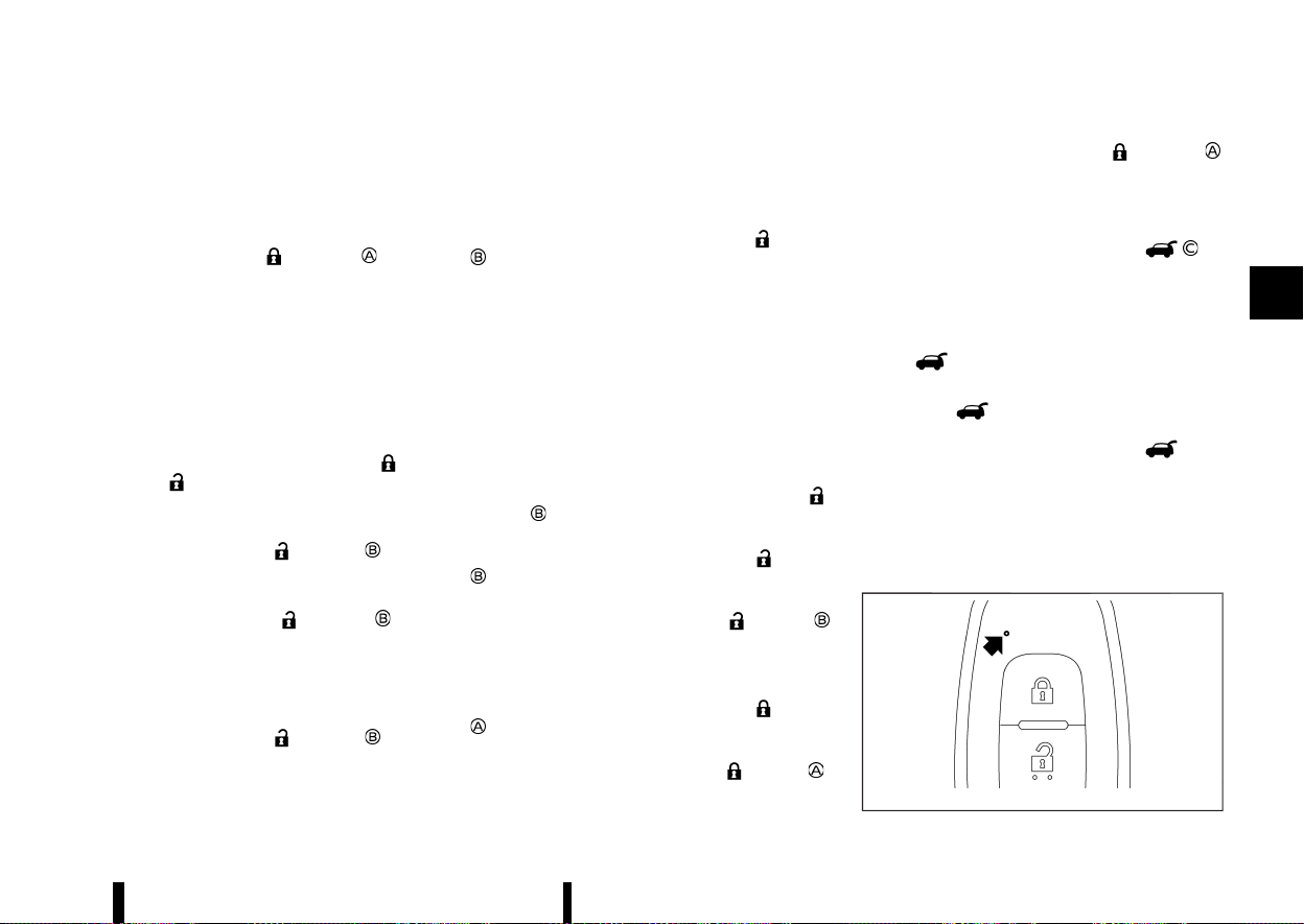
(159,1)
Locking doors
MEVT33A1-D5262080-ABD1-4D76-9C95-01FC9F73DFE8
1. Place the ignition switch in the “OFF” position.
2. Carry the Intelligent Key with you.*
3. Close all the doors.
4. Push the "LOCK"
button on the
Intelligent Key.
5. All the doors and the back door will lock.
*: Doors will lock with the Intelligent Key while
the ignition switch is in the ON position.
Operate the door handles to confirm that the
doors have been securely locked.
Unlocking doors
MEVT33A1-A93EF8B5-C1CC-498F-91E8-A405D427718F
To switch the door unlock mode from one to
another, push and hold the "LOCK"
and
"UNLOCK"
button on the Intelligent Key or
see “[Vehicle Settings]” (P.86).
Selective door unlock mode:
1. Push the “UNLOCK”
button on the
Intelligent Key.
2. The driver’s door will be unlocked.
3. Push the “UNLOCK”
button again
within 5 seconds.
4. All doors will be unlocked.
5. Operate the door handles to open the doors.
All door unlock mode:
1. Push the “UNLOCK”
button on the
Intelligent Key.
2. All doors will be unlocked.
3. Operate the door handle to open the door.
Automatic relock:
All doors will be locked automatically unless one of
the following operations is performed within 30
seconds after pushing the "UNLOCK"
button
while the doors are locked.
* Opening any door (including the back door).
* Pushing the ignition switch.
Opening or closing windows
MEVT33A1-684BC735-6E1F-4782-ACBB-1A986342127E
The windows can be opened or closed with the
Intelligent Key. This function will not operate while
the window timer is activated or the windows
need to be initialised.
See “Power windows” (P.133).
Opening:
To open the windows, push the “UNLOCK”
button on the Intelligent Key for about 3
seconds after the door is unlocked.
To stop opening, release the “UNLOCK”
button
.
If the window open operation is stopped on the
way while pushing the “UNLOCK”
button ,
release and push the button again until the
window opens completely.
Closing:
To close the windows, push the LOCK
button
on the Intelligent Key for about 3 seconds after
the door is locked.
To stop closing, release the LOCK
button .
If the window close operation is stopped on the
way while pushing the LOCK
button ,
release and push the button again until the
window closes completely.
Opening/closing back door (where fitted)
MEVT33A1-16A299E1-8EC4-481B-AD1E-70F185C2E825
1. Push the power back door button for
more than 1 second.
2. The back door will automatically open.
The outside chime sounds 3 times.
To close the back door, push the power back door
button
for more than 1 second.
The back door will automatically close.
If the button
is pushed while the back door is
being opened or closed, the back door will
immediately stop. Pushing the button
again
will reverse the direction of the back door. How-
ever, when the back door is near the fully open
position, it moves in the closing direction and
when the back door is near the fully close position,
it moves in the opening direction.
Intelligent Key button operation light
MEVT33A1-4F8C060A-30F0-42D7-895F-1F47A95892F9
MWBD0037X
Pre-driving checks and adjustments 155
(160,1)
156 Pre-driving checks and adjustments
The light blinks only when you push any button on
the Intelligent Key. The light illumination only
signifies that the Intelligent Key has transmitted a
signal. You may look and/or listen to verify that the
vehicle has performed the intended operation. If
the light does not blink, your battery may be too
weak to communicate to the vehicle. If this occurs,
the battery may need to be replaced.
For additional information regarding the replace-
ment of a battery, see “Intelligent Key battery”
(P.439).
HAZARD INDICATOR OPERATION
MEVT33A1-4226B99C-5BF8-41AF-A0AE-CDA694EB2A3C
When you lock or unlock the doors with the lock or
capacitive unlock sensors (where fitted), request
switch (where fitted) or the remote keyless entry
function, the hazard indicator will flash as a
confirmation.
The following descriptions show how the hazard
indicator will activate when locking or unlocking
the doors.
Operation DOOR LOCK
DOOR UNLOCK
Touching the lock or capacitive unlock
sensor (where fitted)
or pushing back door request switch
(where fitted)
HAZARD - once
HAZARD - twice
Pushing
or button HAZARD - once
HAZARD - twice

(161,1)
MEVT33A1-E521ED90-7BA2-4FC3-91C7-F35E3C88DAF5
Your vehicle is equipped with the following secur-
ity systems:
* Theft warning (where fitted)
* NISSAN Anti-theft System (NATS)*
(* immobilizer)
THEFT WARNING SYSTEM (where fitted)
MEVT33A1-FAE37A89-2583-4992-9463-291C502A9190
The theft warning system provides visual and
audio alarm signals if parts of the vehicle are
disturbed.
For models with ultrasonic sensor
MEVT33A1-203757E2-4EC2-4A81-9804-E82407C97F9E
How to activate system:
1. Close all windows and sunroof (where fitted).
2. Place the ignition switch in the “OFF” position.
3. Carry the Intelligent Key with you and get out
of the vehicle.
4. Make sure the bonnet and the back door are
closed. Close and lock all doors with the
Intelligent Key, the lock sensor (on the front
door handles) (where fitted) or the request
switch (where fitted).
If the bonnet is open, the buzzer will sound.
The buzzer will stop when the bonnet is
correctly closed.
The system will be activated in approximately
20 seconds.
Even when the driver and/or passengers are in
the vehicle, the system will activate with all
doors locked and the ignition switch off. Place
the ignition switch in the ON position to turn the
system off.
If the system malfunctions, the short beep
sounds 5 times when the system is activated.
Have the system checked by a NISSAN dealer or
qualified workshop.
Theft warning system operation:
The warning system will give the following alarm:
* The hazard indicator lights blink and the horn
sounds intermittently for approximately 30
seconds.
* The alarm automatically turns off after ap-
proximately 30 seconds. However, the alarm
reactivates if the vehicle is tampered with
again.
The alarm is activated when:
* operating the door or the back door without
using the Intelligent Key, the capacitive unlock
sensor (on the front door handles) (where
fitted) or the request switch (where fitted).
* opening the bonnet (where fitted).
* the volumetric sensing system (ultrasonic
sensors) is triggered (when it is activated).
* the power supply is disconnected.
How to stop alarm:
* The alarm will stop by unlocking a door with
the capacitive unlock sensor (where fitted), the
request switch (where fitted) or the “UNLOCK”
button on the Intelligent Key.
* The alarm will stop if the ignition switch is
placed in the ON position.
Operation of the ultrasonic sensor:
The ultrasonic sensors (volumetric sensing), detect
movement in the passenger’s compartment. When
the theft warning system is set to the armed
position, it will automatically switch on the ultra-
sonic sensor.
It is possible to exclude the ultrasonic (for example,
when transporting the vehicle on a ferry).
To exclude the ultrasonic:
1. Close all the windows.
2. Place the ignition switch in the “OFF” position.
3. Push the
button until [Settings]
appears in the vehicle information display
and then push the scroll dial. Use the scroll
dial to select [Vehicle Settings]. Then push the
scroll dial.
4. Select [Alarm System]. Then push the scroll
dial. The following options are available:
.
[Always ON]
When this item is selected, the ultrasonic
sensor will activate each time the alarm is
set.
.
[Ask on Exit]
When this item is selected, the system
provides the choice to disable the ultra-
sonic sensor after the ignition switch is
placed in the “OFF” position.
.
[Disable Once]
When this item is selected, the ultrasonic
sensor will be disabled until the next time
the theft warning system is disarmed.
Select [Disabled Once] or [Ask on Exit]. Then
push the scroll dial.
Pre-driving checks and adjustments 157
SECURITY SYSTEM
SECURITY SYSTEM

(162,1)
158 Pre-driving checks and adjustments
5. Close the doors, bonnet and back door. Lock
them using the Intelligent Key, the lock sensor
(where fitted) or the request switch (where
fitted).
The ultrasonic sensor is now excluded from the
theft warning system. All other functions of the
system remain activated until the theft warning
system is disarmed again.
For models without ultrasonic sensor
MEVT33A1-2B635DBD-84C7-400A-AD1D-C52D516EF8AA
How to activate system:
1. Close all windows and sunroof (where fitted).
The system can be armed even if the
windows are open.
2. Place the ignition switch in the “OFF” position.
3. Remove the Intelligent Key from the vehicle.
4. Close all doors, bonnet and back door. Lock all
doors. The doors can be locked with the
Intelligent Key, the lock sensor (on the front
door handles) (where fitted), request switch
(where fitted), power door lock switch or
mechanical key.
Even when the driver and/or passengers are in
the vehicle, the system will activate with all
doors, bonnet, and back door locked with the
ignition switch in the “OFF” position. When
placing the ignition switch in the ON position,
the system will be released.
Theft warning system operation:
The vehicle security system will give the following
alarm:
* The hazard indicator lights blink and the horn
sounds intermittently.
* The alarm automatically turns off after ap-
proximately 27 seconds. However, the alarm
reactivates if the vehicle is tampered with
again.
The alarm is activated by:
* Unlocking the door or opening the back door
without using the button on the Intelligent
Key, the capacitive unlock sensor (on the front
door handles) (where fitted), the request
switch (where fitted) or the mechanical key.
(Even if the door is opened by releasing the
door inside lock knob, the alarm will activate.)
* Opening the bonnet.
How to stop alarm:
* The alarm will stop by unlocking a door with
the capacitive unlock sensor (where fitted), the
request switch (where fitted) or the “UNLOCK”
button on the Intelligent Key.
* The alarm will stop if the ignition switch is
placed in the ON position.
NISSAN ANTI-THEFT SYSTEM (NATS)
MEVT33A1-82475EC2-840C-467B-A31D-97F570513B2F
The NATS (NISSAN Anti-Theft System) will not allow
the engine to start without the use of the
registered key.
If the engine does not start using the registered
Intelligent Key, it may be due to interference
caused by:
* Another Intelligent Key.
* Automated toll road device.
* Automated payment device.
* Other devices that transmit similar signals.
Start the engine using the following procedure:
1. Remove any items that may be causing the
interference away from the Intelligent Key.
2. Start the engine again.
If this procedure allows the engine to start, NISSAN
recommends placing the registered Intelligent Key
separate from other devices to avoid interference.
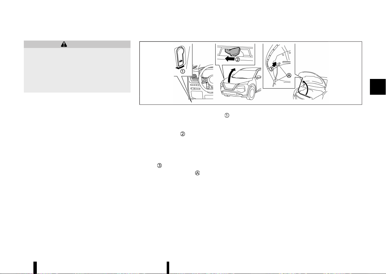
(163,1)
MEVT33A1-DDF67E0E-97E9-454E-A431-36E50A96E436
WARNING
* Make sure the bonnet is completely closed
and latched before driving. Failure to do so
could cause the bonnet to fly open and
result in an accident.
* Never open the bonnet if steam or smoke
is coming from the engine compartment
to avoid injury.
MWAD0150X
1. Pull the bonnet lock release handle located
below the driver’s side instrument panel; the
bonnet springs up slightly.
2. Push the lever
underneath the front of the
bonnet sideways as illustrated with your
fingertips.
3. Raise the bonnet.
4. Remove the support rod and insert it into the
slot
.
Hold the coated parts
when removing or
resetting the support rod. Avoid direct contact
with the metal parts, as they may be hot
immediately after the engine has been stopped.
When closing the bonnet:
1. While supporting the bonnet, return the sup-
port rod to its original position.
2. Slowly lower the bonnet to about 20 to 30 cm
(8 to 12 in) above the bonnet lock, then let it
drop.
3. Make sure it is securely latched.
Pre-driving checks and adjustments 159
BONNET
BONNET
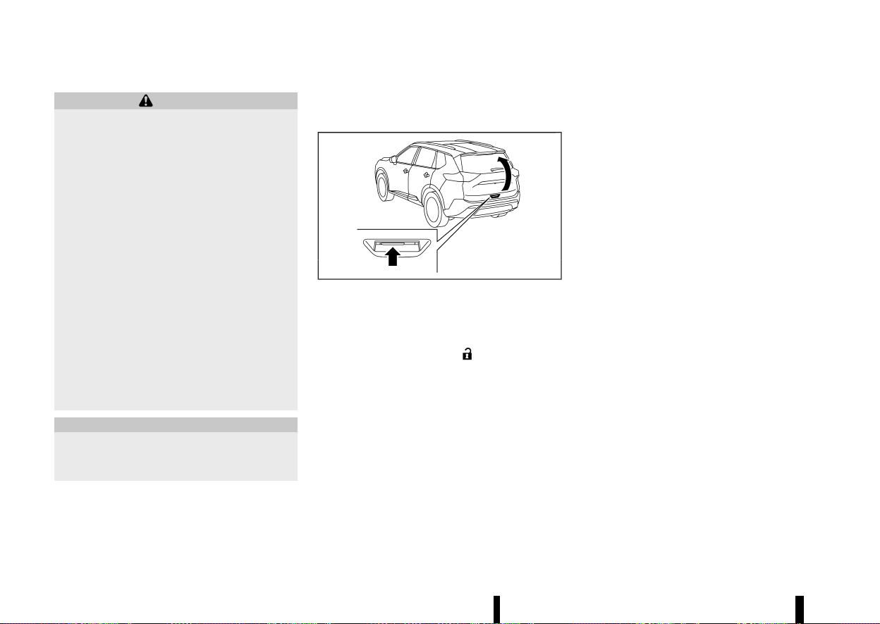
(164,1)
160 Pre-driving checks and adjustments
MEVT33A1-9CA202EA-33F9-40ED-9CE7-79784558EBE6
WARNING
* Always be sure the back door has been
closed securely to prevent it from opening
while driving.
* Do not drive with the back door open. This
could allow dangerous exhaust gases to
be drawn into the vehicle. For additional
information, refer to “Exhaust gas (carbon
monoxide)” (P.238).
* To help avoid risk of injury or death
through unintended operation of the ve-
hicle and or its systems, including entrap-
ment in windows or inadvertent door lock
activation, do not leave children, people
who require the assistance of others or
pets unattended in your vehicle. Addition-
ally, the temperature inside a closed vehi-
cle on a warm day can quickly become
high enough to cause a significant risk of
injury or death to people and pets.
* Always be sure that hands and feet are
clear of the door frame to avoid injury
while closing the back door.
CAUTION
Do not use accessory carriers that attach to
the back door. Doing so will cause damage to
the vehicle.
OPERATING MANUAL BACK DOOR
(where fitted)
MEVT33A1-C3186821-96BC-4777-9B19-B50C79CECD5E
MWAD0151X
To open the back door, unlock it. Pull up the back
door to open.
The back door can be unlocked by:
* pushing the UNLOCK
button on the
Intelligent Key.
* pushing the back door request switch (where
fitted).
* touching the capacitive unlock sensor (where
fitted).
To close the back door, pull down until it securely
locks.
OPERATING POWER BACK DOOR (where
fitted)
MEVT33A1-1D2742E0-29C9-4A49-A058-A3B906739A19
To operate the power back door, the vehicle must
be in the P (Park) position.
The power back door will not operate if the battery
voltage is low.
If the back door is open approximately 150 mm (5.9
in) or less from the fully closed position, power
back door cannot be performed by any switch
operations. To operate the power back door,
manually close the back door.
The power back door operation can be activated
or deactivated in the vehicle information display.
(See “[Vehicle Settings]” (P.86).)
NOTE:
* For models with motion-activated back
door: When washing, waxing or maintaining
your vehicle, placing or replacing the body
cover, or splashing water to the area around
the kick motion sensor, turn off the power
back door.
* If the power open or close operation is
performed consecutively, the safety mode
activates and the operation cannot be per-
formed for a certain period of time. In this
case, wait for a while and then perform the
operation.
BACK DOOR
BACK DOOR
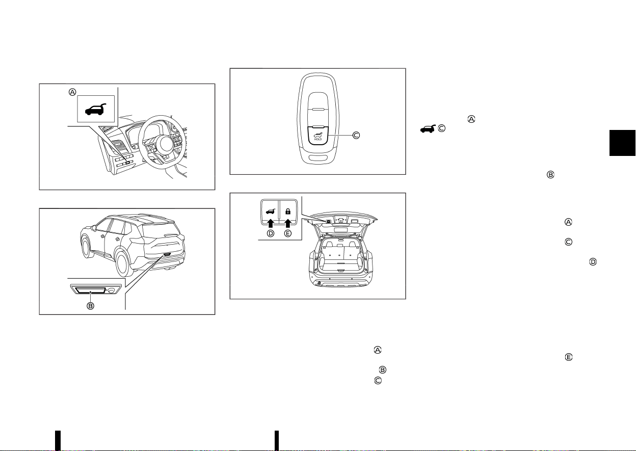
(165,1)
Power open (using switches)
MEVT33A1-94B10E98-9AF8-402B-9D59-B15A1E5F954A
MWAD0233X
Power back door switch — Instrument panel
MWAD0236X
Back door opener switch
MWBD0026X
Power back door button - Key (example)
MWAD0153X
Power back door close and lock switches — Back
door
When the back door is fully closed, the back door
will fully open automatically by:
* pushing the power back door switch
on the
instrument panel for more than 1 second
* pushing the back door opener switch
* pushing the power back door button on the
key for more than 1 second
The outside chime sounds when the back door
starts opening.
NOTE:
The back door can be opened by the power back
door switch
or the power back door button
even if the back door is locked. The back
door can be unlocked and opened indepen-
dently of the other doors, even when they are
locked. The back door must be unlocked (or the
Intelligent Key must be within range) to open
with the back door opener switch
.
Power close (using switches)
MEVT33A1-E6699078-A030-4219-9D44-E361789E00B1
When the back door is fully opened, the back door
will fully close automatically by:
* pushing the power back door switch
on the
instrument panel for more than 1 second
* pushing the power back door button
on the
key for more than 1 second
* pushing the power back door close switch
on the lower part of the back door
The outside chime sounds when the back door
starts closing.
Power close and lock
MEVT33A1-DE002D69-3EE4-4998-94E9-D8F7A6AFD5CA
When the back door is fully opened and the
Intelligent Key is carried with you near the back
door, all the doors and the back door will lock and
the back door will fully close automatically by
pushing the power back door lock switch
on the
lower part of the back door.
The outside chime sounds when the back door
starts closing.
Pre-driving checks and adjustments 161
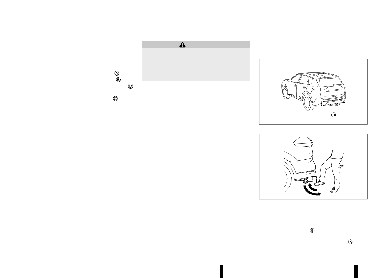
(166,1)
162 Pre-driving checks and adjustments
Stop and reverse function (where fitted)
MEVT33A1-32C0255D-5C8B-4CEB-8EBB-80B59DDCF3FC
The power back door will stop immediately if one
of the following actions is performed during power
open or close.
* pushing the power back door switch
* pushing the back door opener switch
* pushing the power back door close switch
on the lower part of the back door
* pushing the power back door button
on the
key
And then the power back door will move in the
reverse direction if one of the above actions is
performed again.
The outside chime sounds when the back door
starts to reverse.
Auto reverse function
MEVT33A1-C9AA93A1-CBF3-4EA4-AD9B-6CFC13236886
The auto-reverse function enables the back door
to automatically reverse when something is
caught in the back door as it is opening or closing.
When the control unit detects an obstacle, the
back door will reverse and stop.
If a second obstacle is detected, the back door
motion will stop.
A pinch sensor is mounted on each side of the
back door. If an obstacle is detected by the pinch
sensor during power close, the back door will
reverse and stop.
NOTE:
If the pinch sensor is damaged or removed, the
power close function will not operate.
WARNING
There is a small distance immediately before
the closed position that cannot be detected.
Make sure that all passengers keep their
hands, etc., clear from the back door opening
before closing the back door.
Manual mode
MEVT33A1-7EB39826-6304-4883-8641-FCB1271BF5C1
If power operation is not available, the back door
can be operated manually. Power operation may
not be available if the battery voltage is low or if
the back door is open approximately 150 mm (5.9
in) or less from the fully closed position. When the
power back door is turned off, the back door can
be opened manually by pushing the back door
opener switch. If the power back door opener
switch is pushed during power open or close, the
power operation will be cancelled and the back
door can be operated manually. This will allow
normal power operation functions to resume.
MOTION-ACTIVATED BACK DOOR
(where fitted)
MEVT33A1-87A9726B-668E-457D-9749-EC329ADB0E46
MWAD0154X
MJVP0487X
The back door can be operated using a quick
kicking motion under the centre of the rear
bumper.
The kick motion sensor
is located on the back of
the rear bumper. when you move your foot under
and then away from the operating range
similar

(167,1)
to a kicking motion, while carrying the Intelligent
Key with you, the back door will open or close
automatically.
Proper operation technique
* While at the rear of the vehicle, begin making a
quick forward kicking motion.
* Raise your foot straight under the centre of
the rear bumper then immediately return your
foot to the ground in a continuous motion.
* You do not need to hold your foot under the
bumper or move it side to side. Immediately
return your foot to the ground.
* The kicking motion should be straight, smooth
and consistent.
* After your kick motion is complete, step back
and allow the back door to open/close.
* Three beeps will sound and the back door will
begin moving within 2 seconds after the kick.
WARNING
Prevent unintentional back door opening/
closing. There may be conditions when open-
ing/closing the back door is not desired. Keep
the Intelligent Key out of range of the back
door, (2 m (7 ft) or more) or inside the vehicle,
when washing or working around the back of
the vehicle.
NOTE:
* The kick motion sensor may not function
under the following conditions:
— When operating near a location where
strong radio waves are transmitted, such
as a TV tower, power station or broad-
casting station.
— When the vehicle is parked near a parking
meter.
* The power back door may not operate when
your foot remains in the operating range
.
CAUTION
* When the Intelligent Key is carried with you
near the back door, even someone, who
does not carry the Intelligent Key, may be
able to open or close the back door with a
kick motion.
* Do not perform a kick motion near the
exhaust system components while they
are hot. You may severely burn yourself.
* Do not perform a kick motion on an
unstable place (for example, on a slope or
a muddy ground, etc.).
Power open or close function
MEVT33A1-94248880-4054-45A3-8FA5-C721B521EEE2
The back door will fully open automatically using
the kick motion sensor.
1. Carry the Intelligent Key.
2. Move your foot under and away from the rear
bumper similarly to a kicking motion within
the operation range of the kick motion sensor.
3. The back door will automatically open or close.
Stop and reverse function
MEVT33A1-765D1EB4-6DF0-44CA-A8A2-32368545D371
The power back door will stop immediately if a kick
motion is performed during power open or close.
The back door can be stopped even if you do not
carry the Intelligent Key.
And then the power back door will move in the
reverse direction if a kick motion is performed
again. The power back door can be reversed when
you carry the Intelligent Key.
GARAGE MODE SYSTEM (where fitted)
MEVT33A1-52632399-52A3-41DB-8244-C0725D0158B1
The back door can be set to open to a specific
height by performing the following:
1. Open the back door.
2. Pull the back door down to the desired
position and hold the back door (the back
door will have some resistance when being
manually adjusted).
3. While holding the back door in position, press
and hold the power back door close switch
located on the back door for approximately 3
seconds or until 2 beeps are heard.
The back door will open to the selected position
setting. To change the position of the back door,
repeat steps 1-3 for setting the position of the back
door.
CAUTION
Do not set the height of the back door below
approximately 1/3 of the way to the floor using
garage mode. Even if you set the height below
approximately 1/3 of the way to the floor, the
Pre-driving checks and adjustments 163
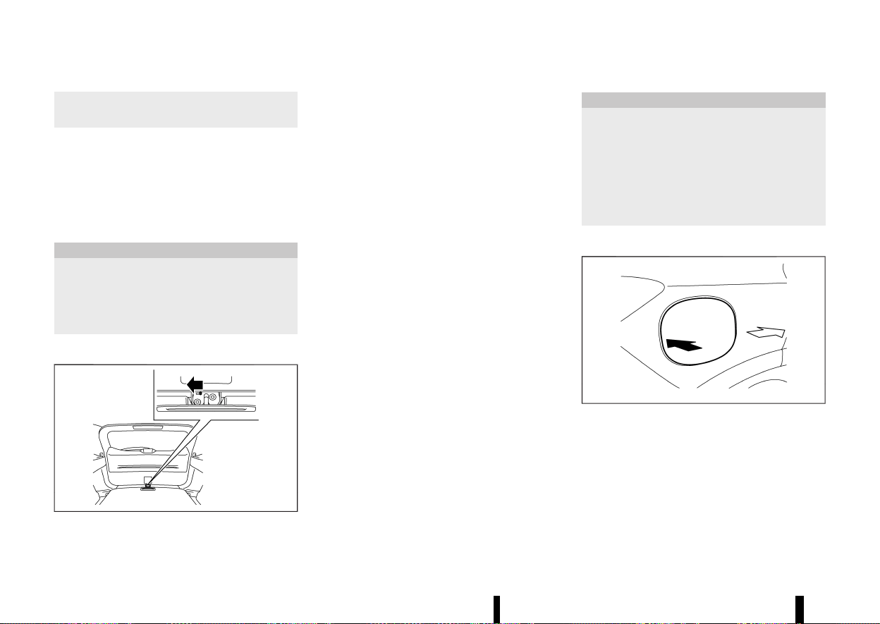
(168,1)
164 Pre-driving checks and adjustments
height will automatically be set to approxi-
mately 1/3 of the way to the floor.
AUTO CLOSURE (where fitted)
MEVT33A1-E67016E4-7E72-4C61-871D-F1C8E81D9324
When the back door reaches the secondary
position, the closure motor engages and pulls the
back door to its primary latch position.
Do not apply excessive force when the auto
closure is operating. Excessive force applied
may cause the mechanism to malfunction.
CAUTION
* The back door will automatically close
from the secondary position. To avoid
pinching, keep hands and fingers away
from back door opening.
* Do not let children operate the back door.
BACK DOOR RELEASE LEVER
MEVT33A1-84B20BF7-6050-413C-B943-F274AE14B550
MWAD0155X
If the back door cannot be opened due to a
discharged battery, follow these steps.
1. Fold the rear seats down. (See “Seats” (P.16).)
2. Insert a suitable tool in the access opening.
Move the release lever to the left. The back
door will be unlatched.
3. Push the back door up to open.
Contact a NISSAN dealer or qualified workshop as
soon as possible for repair.
MEVT33A1-00F653FB-C04F-403C-85F5-83A24D3090E8
CAUTION
* Avoid applying direct water pressure, such
as high-pressured sprayer, on or around
the fuel-filler lid.
* Be sure to close the fuel-filler lid before
using an automatic car wash or a high-
pressured car wash.
* Never use fuel additives. Additives may
cause damage to the engine (for Europe).
OPENING THE FUEL-FILLER LID
MEVT33A1-232776DC-41D5-442C-B49A-681435FB8699
MWAD0231X
To open the fuel-filler lid, push the middle left side
of the lid.
FUEL-FILLER LID
FUEL-FILLER LID
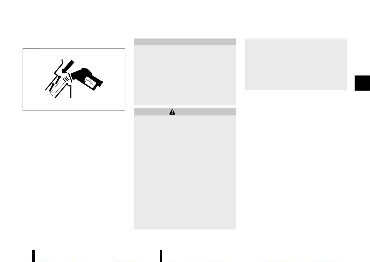
(169,1)
HOW TO REFUEL
MEVT33A1-D78C472D-DEB1-43D1-82E6-5180D4CDB920
MJVP0524X
The fuel tank is not equipped with a fuel-filler cap.
After opening the fuel-filler lid, insert the fuel pump
nozzle directly into the fuel-filler opening. When
the fuel pump nozzle is pulled out, the fuel-filler
opening will be sealed.
To refuel:
Be sure to insert the fuel pump nozzle into the
fuel-filler opening at one motion and as far as it will
go before fueling.
Never move the nozzle during refuelling.
Pull out the nozzle approximately 5 seconds after
the fuel pump nozzle shuts off automatically (initial
shut-off).
Close the fuel-filler lid after refuelling.
If you need to refuel from a portable fuel container,
use the funnel supplied with your vehicle. (See
“When refuelling from a portable fuel container”
(P.166).)
CAUTION
* Do not attempt to open the flaps on the
fuel-filler opening using any tool other
than the fuel pump nozzle.
* This fuel-filler opening is only conformable
to normal fuel pump nozzles at gas sta-
tions. Using a nozzle with a small diameter
may damage the opening and the fuel
system.
* If fuel is spilled on the vehicle body, flush it
away with water to avoid paint damage.
WARNING
* Petrol is extremely flammable and highly
explosive under certain conditions. You
could be burned or seriously injured if it
is misused or mishandled. Always stop
engine and do not smoke or allow open
flames or sparks near the vehicle when
refuelling.
* Do not attempt to top off the fuel tank
after the fuel pump nozzle shuts off auto-
matically. Continued refuelling may cause
fuel overflow, resulting in fuel spray and
possibly a fire.
* Never pour fuel into the throttle body to
attempt to start your vehicle.
* Do not fill a portable fuel container in the
vehicle. Static electricity can cause an
explosion of flammable liquid, vapour or
gas in any vehicle. To reduce the risk of
serious injury or death when filling porta-
ble fuel containers:
— Always place the container on the
ground when filling.
— Do not use electronic devices when
filling.
— Keep the pump nozzle in contact with
the container while you are filling it.
— Use only approved portable fuel con-
tainers for flammable liquid.
Pre-driving checks and adjustments 165
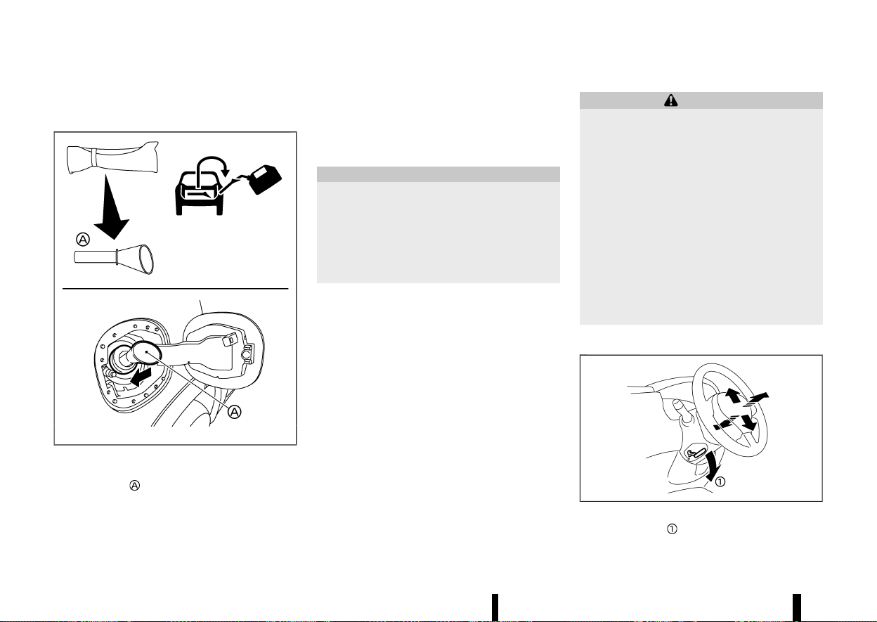
(170,1)
166 Pre-driving checks and adjustments
WHEN REFUELLING FROM A PORTABLE
FUEL CONTAINER
MEVT33A1-E9A389E1-7406-470E-87AB-94F4A5257AB9
MWAD0214X
If you need to refuel from a portable fuel container,
use the funnel
stored in the tool bag (located
under the luggage board).
Be sure to insert the funnel into the fuel-filler
opening slowly and fully. Insert the nozzle of the
portable fuel container into the opening along the
funnel and fill the fuel tank.
After refuelling, remove the funnel from the fuel-
filler opening. Wipe the funnel clean and return it to
the tool bag.
CAUTION
* Do not insert the nozzle of the portable
fuel container directly into the fuel-filler
opening. Doing so may damage the open-
ing and the fuel system.
* Use only the funnel provided with your
vehicle. Otherwise, the fuel-filler opening
and the fuel system may be damaged.
MEVT33A1-7AAC6169-F454-4DB3-8227-6004975E411D
WARNING
* Do not adjust the steering wheel while
driving. You could lose control of your
vehicle and cause an accident.
* Do not adjust the steering wheel any closer
to you than is necessary for proper steer-
ing operation and comfort. The driver’s air
bag inflates with great force. If you are
unrestrained, leaning forward, sitting side-
ways or out of position in any way, you are
at greater risk of injury or death in a crash.
You may also receive serious or fatal
injuries from the air bag if you are up
against it when it inflates. Always sit back
against the seatback and as far away as
practical from the steering wheel. Always
use the seat belts.
TILT AND TELESCOPIC OPERATION
MEVT33A1-98D4C859-8310-413D-B671-8D41BD53A06D
MWAD0127X
Pull the lock lever down and adjust the steering
wheel up, down, forward or rearward to the
STEERING WHEEL
STEERING WHEEL
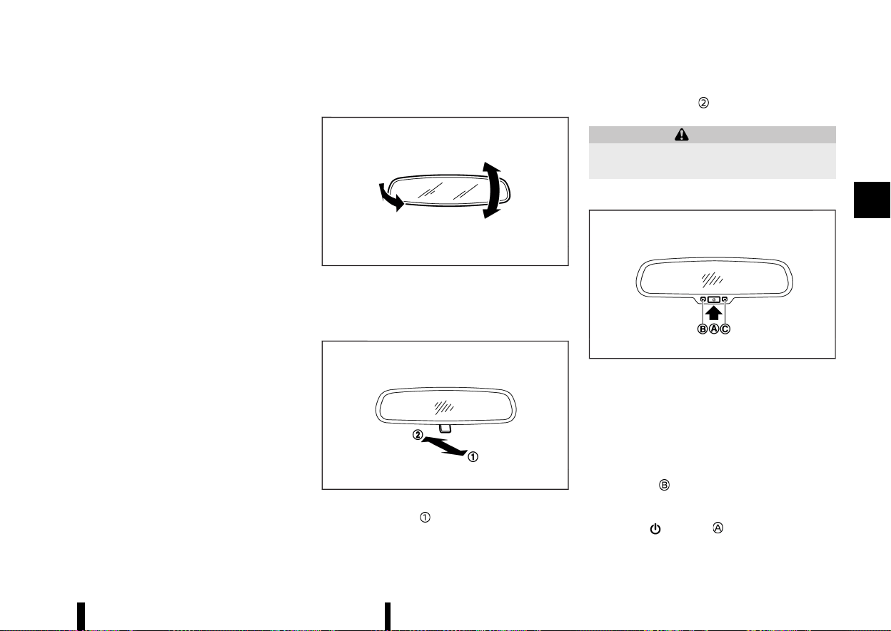
(171,1)
desired position. Push the lock lever up securely to
lock the steering wheel in place.
MEVT33A1-7EFE8433-9BF0-4D21-9989-FB2D38316637
INSIDE REARVIEW MIRROR
MEVT33A1-9C609EA8-A3B9-4975-983B-54EA13FA811E
MSPA2447
Adjust the angle of the inside rearview mirror to
the desired position.
Manual anti-glare type (where fitted)
MEVT33A1-DDCAE70E-4A99-41B9-9B31-42A97C1BBADF
MSPA2143
The night position will reduce glare from the
headlights of vehicles behind you at night.
Use the day position
when driving in daylight
hours.
WARNING
Use the night position only when necessary,
because it reduces rear view clarity.
Automatic anti-glare type (where fitted)
MEVT33A1-D65B8BA1-A543-4DF1-8D0E-D83CAFB8F8E5
MSPA2162
The inside rearview mirror is designed so that it
automatically changes reflection according to the
intensity of the headlights of the following vehicle.
The anti-glare system will be automatically turned
on when the ignition switch is placed in the ON
position.
When the anti-glare system is turned on, the
indicator light
will illuminate and excessive glare
from the headlights of the vehicle behind you will
be reduced.
Push the
switch to make the inside
rearview mirror operate normally. The indicator
Pre-driving checks and adjustments 167
MIRRORS
MIRRORS
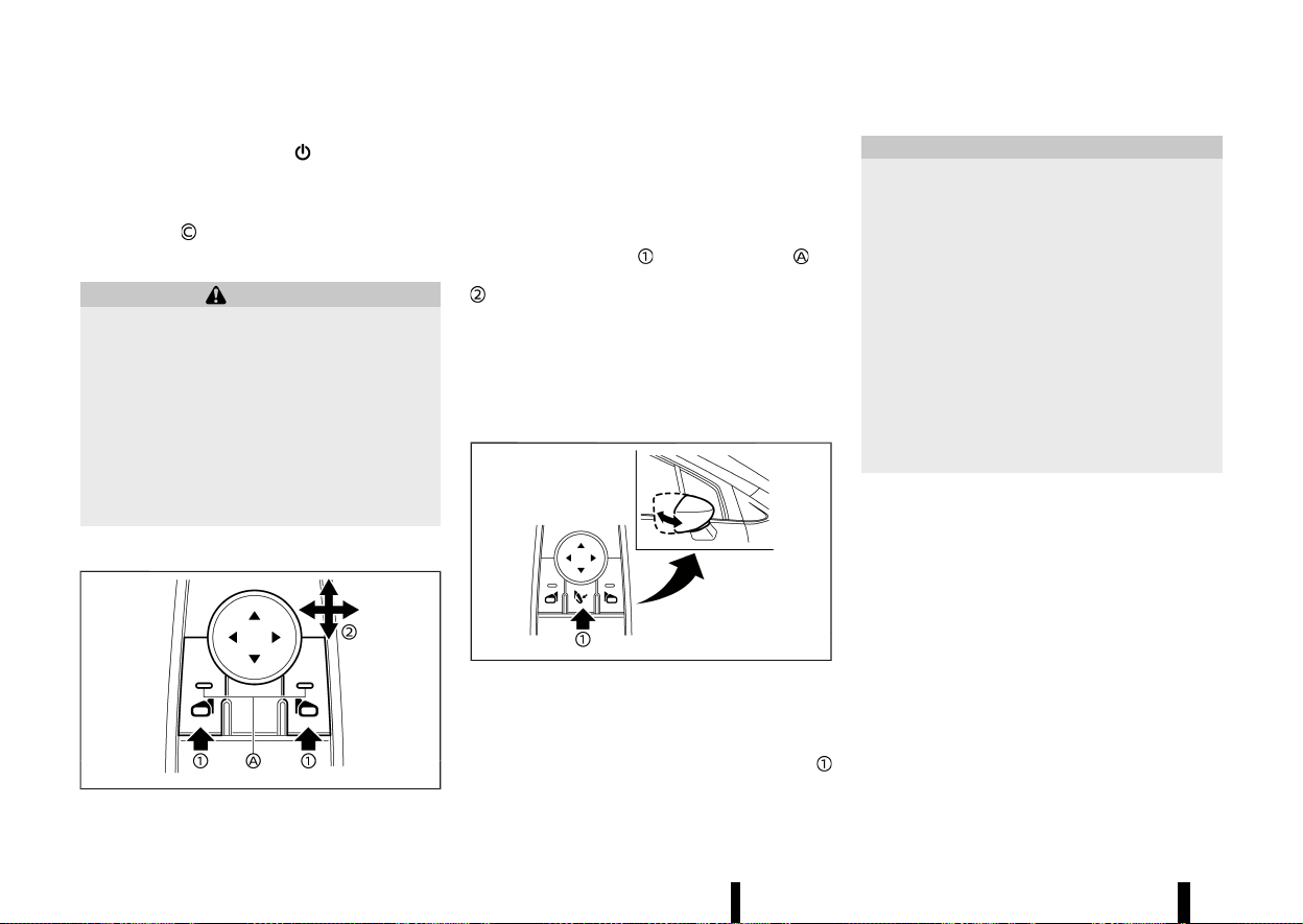
(172,1)
168 Pre-driving checks and adjustments
light will turn off. Push the switch again to
turn the system on.
Do not hang any objects on the mirror or apply
glass cleaner. Doing so will reduce the sensitivity
of the sensor
, resulting in improper operation.
OUTSIDE REARVIEW MIRRORS
MEVT33A1-510D14F7-96A8-42DE-A36F-11C39E241D3B
WARNING
* Never touch the outside rearview mirrors
while they are in motion. Doing so may
pinch your fingers or damage the mirror.
* Never drive the vehicle with the outside
rearview mirrors folded. This reduces rear
view visibility and may lead to an accident.
* Objects viewed in the outside mirror are
closer than they appear (where fitted).
* The picture dimensions and distance in the
outside mirrors are not real.
Adjusting
MEVT33A1-8B70B968-C9B3-4093-8096-7A9C567F354D
MWAD0229X
The outside rearview mirror control switch is
located on the driver’s armrest.
The outside rearview mirror will operate only when
the ignition switch is in the ON position.
Push either the right or left switch to select the
right or left side mirror
(the indicator light on
the selected mirror switch illuminates), then adjust
using the control switch.
Defogging
MEVT33A1-14D9F667-0B94-4F18-87C9-A3D0BA517EA3
The outside rearview mirrors will be heated when
the rear window defogger switch is operated. (See
“Defogger switch” (P.119).)
Folding
MEVT33A1-A82EEE6A-D258-422C-8E76-9A4E1A98209A
MWAD0308X
The outside rearview mirror remote control oper-
ates when the ignition switch is in the ON position.
The outside rearview mirrors automatically fold
when the outside rearview mirror folding switch
is pushed in. To unfold, push the switch again.
CAUTION
* Continuously performing the fold/unfold
operation of the outside rearview mirror
may cause the switch to stop the opera-
tion.
* Do not touch the mirrors while they are
moving. Your hand may be pinched, and
the mirror may malfunction.
* Do not drive with the mirrors stored. You
will be unable to see behind the vehicle.
* If the mirrors were folded or unfolded by
hand, there is a chance that the mirror will
move forward or backward during driving.
If the mirrors were folded or unfolded by
hand, be sure to adjust them again elec-
trically before driving.
Automatic fold:
The outside rearview mirrors automatically fold
when the doors are locked with the Intelligent Key,
the lock sensors (where fitted) or the request
switch (where fitted). The mirrors unfold when the
doors are unlocked with the Intelligent Key, the
capacitive unlock sensors (where fitted) or the
request switch (where fitted), or when the ignition
switch is placed in the ON position.
Reverse tilt-down feature (where fitted)
MEVT33A1-A4E4C8ED-7C99-4090-AE3A-FB1DE37D796D
When reversing the vehicle, the right or left outside
mirror will turn downward automatically to pro-
vide better rear visibility.
1. Place the ignition switch in the "ON" position.
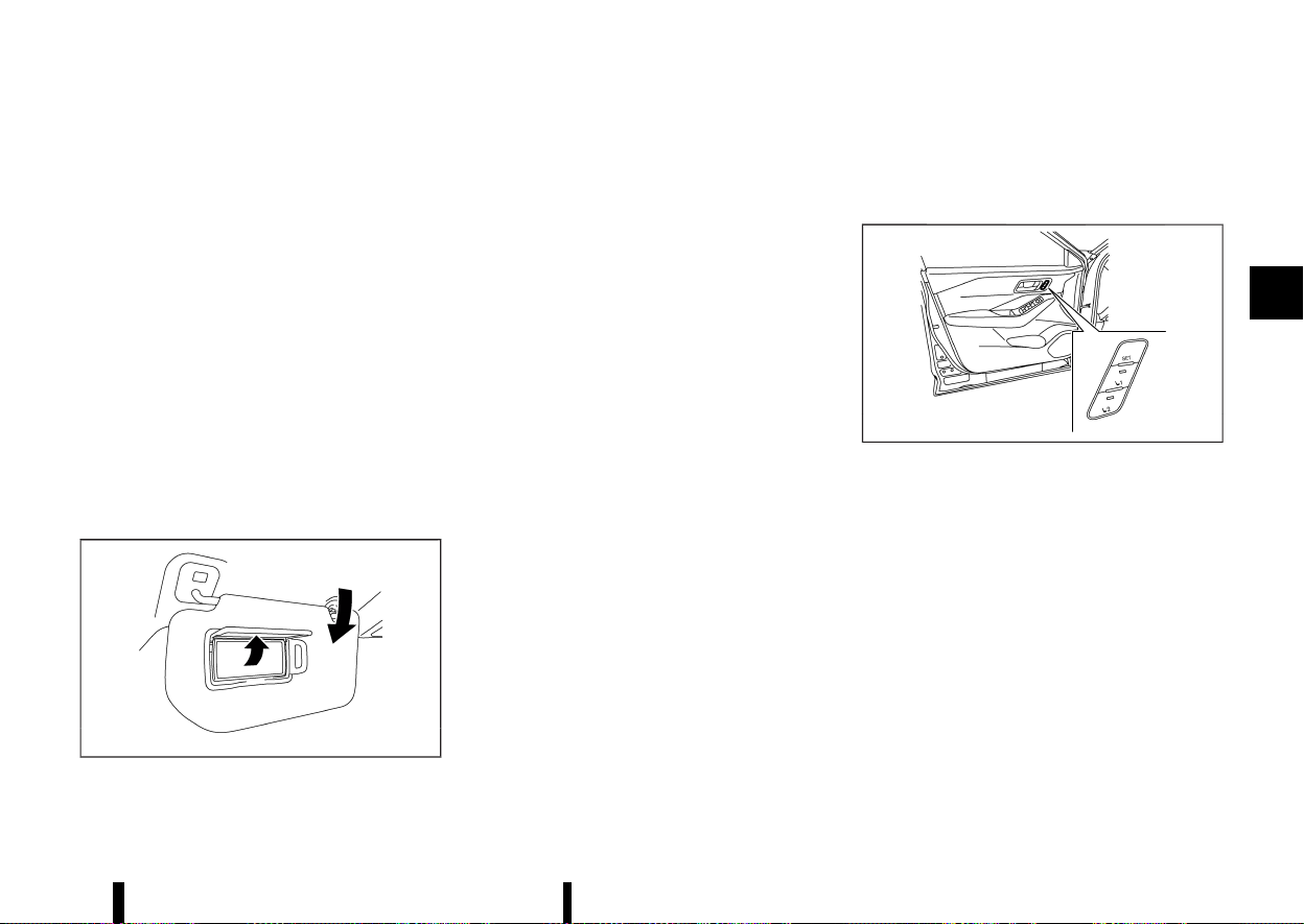
(173,1)
2. Move the shift lever to the "R" (Reverse)
position.
3. Choose the right or left outside mirror by
operating the outside mirror control switch.
4. The selected outside mirror surface moves
downward.
When one of the following conditions has oc-
curred, the outside mirror surface will return to its
original position.
* The shift lever is moved out of the "R"
(Reverse) position.
* The vehicle speed exceeds 8 km/h (5 MPH).
* The selected outside mirror is deselected
using the outside mirror control switch.
* The ignition switch is placed in the "OFF"
position.
* The engine is stopped.
VANITY MIRROR
MEVT33A1-21E8F75F-AC0C-4F4E-9E32-61A89D0A8B52
MWAD0238X
To use the vanity mirror, pull down the sun visor
and pull up the cover.
MEVT33A1-AAD2D952-EBAA-47C4-9350-802524DBC0CF
The automatic drive positioner system has the
following features:
* Memory storage function
* Entry/exit function
MWAD0228X
Automatic drive positioner switch (driver’s side
shown; passenger side similar)
MEMORY STORAGE FUNCTION
MEVT33A1-6CE8018B-A18D-44AB-AE48-5C55D7EDEB86
Two positions for the driver’s seat, front passen-
ger’s seat (where fitted), and outside mirrors
(where fitted) can be stored in the automatic drive
positioner switch. Follow these procedures to use
the memory system.
1. Adjust the driver’s seat and outside mirrors
(where fitted) to the desired positions by
manually operating each adjusting switch.
For additional information, refer to “Seats”
(P.16) and “Outside rearview mirrors” (P.168).
2. Push the <SET> switch and, within 5 seconds,
push the automatic drive positioner switch (1
or 2).
Pre-driving checks and adjustments 169
AUTOMATIC DRIVE POSITIONER
(where fitted)
AUTOMATIC DRIVE POSITIONER
(where fitted)

(174,1)
170 Pre-driving checks and adjustments
3. The indicator light for the pushed automatic
drive positioner switch will come on and stay
on for approximately 5 seconds.
4. The chime will sound if the memory has been
stored.
NOTE:
If a new memory position is stored in the same
automatic drive positioner switch, the previous
memory position will be overwritten by the new
stored position.
Confirming memory storage
MEVT33A1-A7FCB21D-8B1E-4CD3-A052-F0BAB238A23D
Push the <SET> switch. If a memory position has
not been stored in the switch (1 or 2) the indicator
light for the respective switch will come ON for
approximately 0.5 seconds. If a memory position
has been stored in the switch (1 or 2) then the
indicator light for the respective switch will stay
ON for approximately 5 seconds.
Recalling switch memory positions
MEVT33A1-C64C4511-C531-4150-97EB-8A18D53BA53C
To recall the manually stored positions, push the
automatic drive positioner switch (1 or 2). The
driver’s seat and the outside mirrors (where fitted)
will move to the positions stored in the automatic
drive positioner switch.
Linking log-in function to a stored memory
position (models with navigation system)
MEVT33A1-FB4B571E-A7C4-4D67-B2EC-E5A0D2DD0B9D
The log-in function can be linked to a stored
memory position with the following procedure.
1. Place the ignition switch in the "ON" position
while carrying the Intelligent Key that was
registered to the vehicle with a log-in function.
NOTE:
Make sure the Intelligent Key is far apart.
Otherwise, the vehicle may detect the wrong
Intelligent Key.
2. Adjust the position of the driver’s seat and
outside mirrors (where fitted). (See “Seats”
(P.16) and “Outside rearview mirrors” (P.168).)
3. Place the ignition switch in the "OFF" position.
The next time you log in (selecting the user on the
display) after placing the ignition switch in the
"ON" position while carrying the Intelligent Key, the
system will automatically adjust to the memorised
driving position. (See the separate NissanConnect
Owner’s Manual.)
Linking an Intelligent Key to a stored memory
position (models without navigation system)
MEVT33A1-900BC8A4-970E-48BF-BA75-AF919FCB6326
Each Intelligent Key can be linked to a stored
memory position (automatic drive positioner
switch 1 or 2) with the following procedure.
1. Follow steps 1-3 in the “Memory storage
function” (P.169) for storing the memory posi-
tion.
2. The indicator light for the pushed automatic
drive positioner switch will come on. While the
indicator light is on for 5 seconds, press the
button and the button on the
Intelligent Key in succession. The indicator
light of the linked automatic drive positioner
switch will blink. After the indicator light goes
off, the Intelligent Key is linked to that memory
setting.
Once it is linked, when ignition switch is placed in
the "OFF" position, pressing the
button on the
Intelligent Key will move the driver’s seat and
outside mirrors (where fitted) to the linked auto-
matic drive positioner switch position.
NOTE:
If a new memory position is stored in the linked
automatic drive positioner switch, then the
Intelligent Key will link the new position and
overwrites the previous position.
ENTRY/EXIT FUNCTION
MEVT33A1-0680D08F-6820-466E-96CB-5CB35BE09B7D
This system is designed so that the driver’s seat
will automatically move when the shift position is
in the "P" (Park) position. This allows the driver to
get into and out of the driver’s seat more easily.
The driver’s seat will slide backward:
* When the driver’s door is opened with the
ignition switch placed in the "OFF" position.
* When the ignition switch is changed from "ON"
to "OFF" with the driver’s door open.
The driver’s seat will return to the previous
position:
* When the ignition switch is placed in the "ON"
position while the shift position is in the "P"
(Park) position.
The entry/exit function can be cancelled through
[Vehicle Setting] in the vehicle information display
by performing the following:
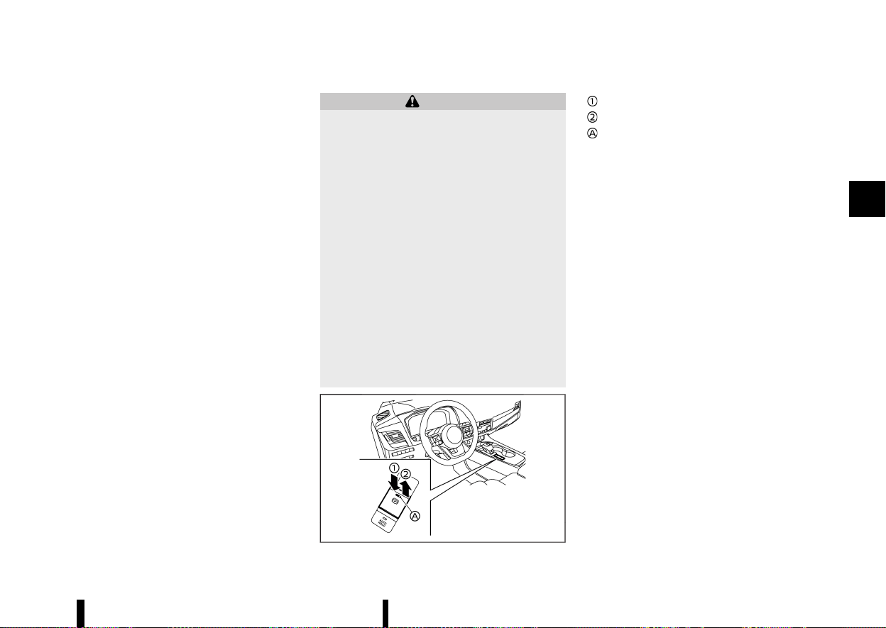
(175,1)
* Switch the [Exit Seat Slide] from ON to OFF. For
additional information, refer to “[Vehicle Set-
tings]” (P.86).
SYSTEM OPERATION
MEVT33A1-EA9D7073-2060-4129-A00E-F4552E6A97FE
The automatic drive positioner system will not
work or will stop operating under the following
conditions:
* When the vehicle is moving. (The driver’s seat
returning function can be operated if the
vehicle speed is below 3km/h (2 MPH).)
* When any of the automatic drive positioner
switches are pushed while the automatic drive
positioner system is operating.
* When the switch for the driver’s seat is pushed
while the automatic drive positioner system is
operating.
* When the seat has already been moved to the
memorised position.
* When no seat position is stored in the auto-
matic drive positioner switch.
* When the shift lever is moved from "P" (Park)
to any other position.
MEVT33A1-31EC2358-F7E9-4615-8367-3344BACF4D60
WARNING
* Never drive the vehicle with the parking
brake applied. The brake will overheat and
fail to operate and will lead to an accident.
* Never release the parking brake from out-
side the vehicle. If the vehicle moves, it will
be impossible to push the footbrake pedal
and will lead to an accident.
* Never use the shift lever in place of the
parking brake. When parking, be sure the
parking brake is fully applied.
* To help avoid risk of injury or death
through unintended operation of the ve-
hicle and/or its systems, do not leave
children, people who require the assis-
tance of others or pets unattended in your
vehicle. Additionally, the temperature in-
side a closed vehicle on a warm day can
quickly become high enough to cause a
significant risk of injury or death to people
and pets.
MWAD0357X
Release
Apply
Indicator light
The electronic parking brake can be applied or
released automatically or by operating the parking
brake switch.
AUTOMATIC OPERATION
MEVT33A1-BCEE29E8-63E0-4900-BB59-CE85565CAEB5
The electronic parking brake will apply automati-
cally under any of the following conditions while
the braking force is maintained by Automatic
brake hold function:
* When the ignition switch is placed in the “OFF”
position.
* When the shift position is placed in the P (Park)
position.
* When the driver’s door is opened.
* When the driver’s seat belt is unfastened.
* When the braking force is applied by Auto-
matic brake hold function for 3 minutes or
longer.
* When electronic parking brake is applied
manually.
* When a malfunction occurs in Automatic
brake hold function.
The electronic parking brake is automatically
released as soon as the vehicle starts while the
accelerator pedal is depressed under the following
conditions.
* While the engine is running.
* When the shift position is in the D (Drive) or R
(Reverse) position.
Pre-driving checks and adjustments 171
PARKING BRAKE
PARKING BRAKE

(176,1)
172 Pre-driving checks and adjustments
* When the driver’s door is closed.
The electronic parking brake is automatically
released within 5 seconds after the shift position
is placed in the D (Drive) or R (Reverse) position
even if the driver’s door is opened. Be sure to close
the door before starting the vehicle.
WARNING
* When Automatic brake hold function is
activated, the electronic parking brake will
not be automatically applied when the
engine is stopped without using the igni-
tion switch (for example, by engine stal-
ling).
Without the vehicle stationary, the electro-
nic parking brake will not be automatically
applied even if the engine is turned off
with the ignition switch.
* Before leaving the vehicle, place the shift
position in the P (Park) position and check
that the electronic parking brake warning
light is illuminated to confirm that the
electronic parking brake is applied. The
electronic parking brake warning light will
remain on for a period of time after the
driver’s door is locked.
CAUTION
When parking in an area where the outside
temperature is below 0°C (32°F), the electronic
parking brake, if applied, may freeze in place
and may be difficult to release.
For safe parking, it is recommended that you
place the shift position in the P (Park) position
and securely block the wheels.
NOTE:
* To keep the electronic parking brake re-
leased after the engine is turned off, place
the ignition switch in the “OFF” position,
depress the brake pedal and push down the
parking brake switch before opening the
driver’s door.
* If a malfunction occurs in the electronic
parking brake system (for example, due to
battery discharge), it is recommended to
contact a NISSAN dealer or qualified work-
shop.
* Under the following conditions, the electro-
nic parking brake will automatically be
applied and the braking force of Automatic
brake hold will be released.
— The braking force is applied by Automatic
brake hold function for 3 minutes or
longer.
— The vehicle is in the P (Park) position.
— Electronic parking brake is applied manu-
ally.
— The driver’s seat belt is unfastened.
— The driver’s door is opened.
— The ignition switch is placed in the “OFF”
position.
— A malfunction occurs in Automatic brake
hold function.
* Make sure that the electronic parking brake
system warning light is OFF before starting
the vehicle.
MANUAL OPERATION
MEVT33A1-9D1D08C0-C0ED-48FD-BDEB-71247921F43C
To apply: When the vehicle is stopped, pull the
parking brake switch
up. (The electronic parking
brake will apply even if the ignition switch is placed
in the “OFF” position.) The indicator light
on the
switch and the electronic parking brake warning
light
(red) will illuminate.
To release: With the ignition switch in the ON
position, depress the brake pedal and push the
parking brake switch down
. The indicator light
and the electronic parking brake warning light
(red) will turn off.
Before driving, check that the electronic parking
brake warning light (red) turns off. For additional
information, see “Warning lights, indicator lights
and audible reminders” (P.74).
NOTE:
* While the electronic parking brake is applied
or released, an operating sound is heard
from the lower side of the rear seat. This is
normal and does not indicate a malfunction.
* When the electronic parking brake is fre-
quently applied and released in a short
period of time, the electronic parking brake
system warning light may blink and the
electronic parking brake may not operate
in order to prevent the electronic parking
brake system from overheating. If this oc-
curs, operate the parking brake switch again
after waiting approximately 1 minute.
* If the electronic parking brake must be
applied while driving in an emergency, pull
up and hold the parking brake switch. When

(177,1)
you release the parking brake switch, the
electronic parking brake will be released.
* While pulling up the parking brake switch
during driving, the electronic parking brake
is applied and a chime sounds. The electro-
nic parking brake warning light (red) and the
indicator light on the parking brake switch
illuminate. This does not indicate a malfunc-
tion. The electronic parking brake warning
light (red) and the indicator light on the
parking brake switch will turn off when the
electronic parking brake is released.
* When pulling the parking brake switch up
with the ignition switch in the “OFF” position,
the indicator light on the parking brake
switch will continue to illuminate for a short
period of time.
When towing a trailer
MEVT33A1-7DED385B-2BCD-45C0-82FC-D263A5222BDA
Depending on the weight of the vehicle and trailer
and the steepness of the slope, there may be a
tendency for the vehicle to move backwards when
starting from a standstill. When this occurs, you
can use the parking brake switch in the same way
as a conventional lever type parking brake.
Before starting on sloping roads when towing a
trailer, be sure to read the following to prevent the
vehicle from moving backward unintentionally.
* Release the parking brake switch as soon as
the engine is delivering enough torque to the
wheels.
MEVT33A1-5B41481A-DB7B-485D-9A0D-C981078DE6F8
Automatic brake hold function maintains the
braking force without the driver having to depress
the brake pedal when the vehicle is stopped at a
traffic light or intersection. As soon as the driver
depresses the accelerator pedal again, Automatic
brake hold function is deactivated and the braking
force is released. The operating status of Auto-
matic brake hold can be displayed.
WARNING
* Automatic brake hold function is not de-
signed to hold the vehicle on a steep hill or
slippery road. Never use Automatic brake
hold function when the vehicle is stopped
on a steep hill or slippery road. Failure to
do so may cause the vehicle to move.
* Warnings may appear to request that the
driver retake control by depressing the
brake pedal.
* When Automatic brake hold function is
activated but fails to maintain the vehicle
at a standstill, depress the brake pedal to
stop the vehicle. If the vehicle unexpect-
edly moves due to outside conditions, the
chime may sound and warnings may
appear.
* Be sure to deactivate Automatic brake
hold function when using a drive-thru car
wash or towing your vehicle.
* Make sure the vehicle is in the P (Park)
position and apply the electronic parking
brake when parking your vehicle, riding on
or off the vehicle, or loading or unloading
luggage. Failure to do so could cause the
vehicle to move or roll away unexpectedly
and result in serious personal injury or
property damage.
* If any of the following conditions occur,
Automatic brake hold function may not
function. Have the system checked
promptly. It is recommended that you visit
a NISSAN dealer or qualified workshop for
this service.
— A warning message appears.
— The indicator light on Automatic brake
hold switch does not illuminate when
the switch is pushed.
Failure to operate the vehicle in accor-
dance with these conditions could cause
the vehicle to move or roll away unexpect-
edly and result in serious personal injury or
property damage.
* Automatic brake hold function will not be
activated if the slip indicator light, electro-
nic parking brake warning light, electronic
parking brake system warning light, or
master warning light illuminates and the
chassis control warning message appears.
* To maintain the braking force to keep the
vehicle to a standstill, a noise may be
heard. This is not a malfunction.
* Automatic brake hold function is operated
by applying sufficient braking force to hold
the vehicle in its place, so there are cases
when this hold function is maintained even
if the accelerator pedal is depressed. In
this situation, it is advised to depress the
Pre-driving checks and adjustments 173
AUTOMATIC BRAKE HOLD
AUTOMATIC BRAKE HOLD
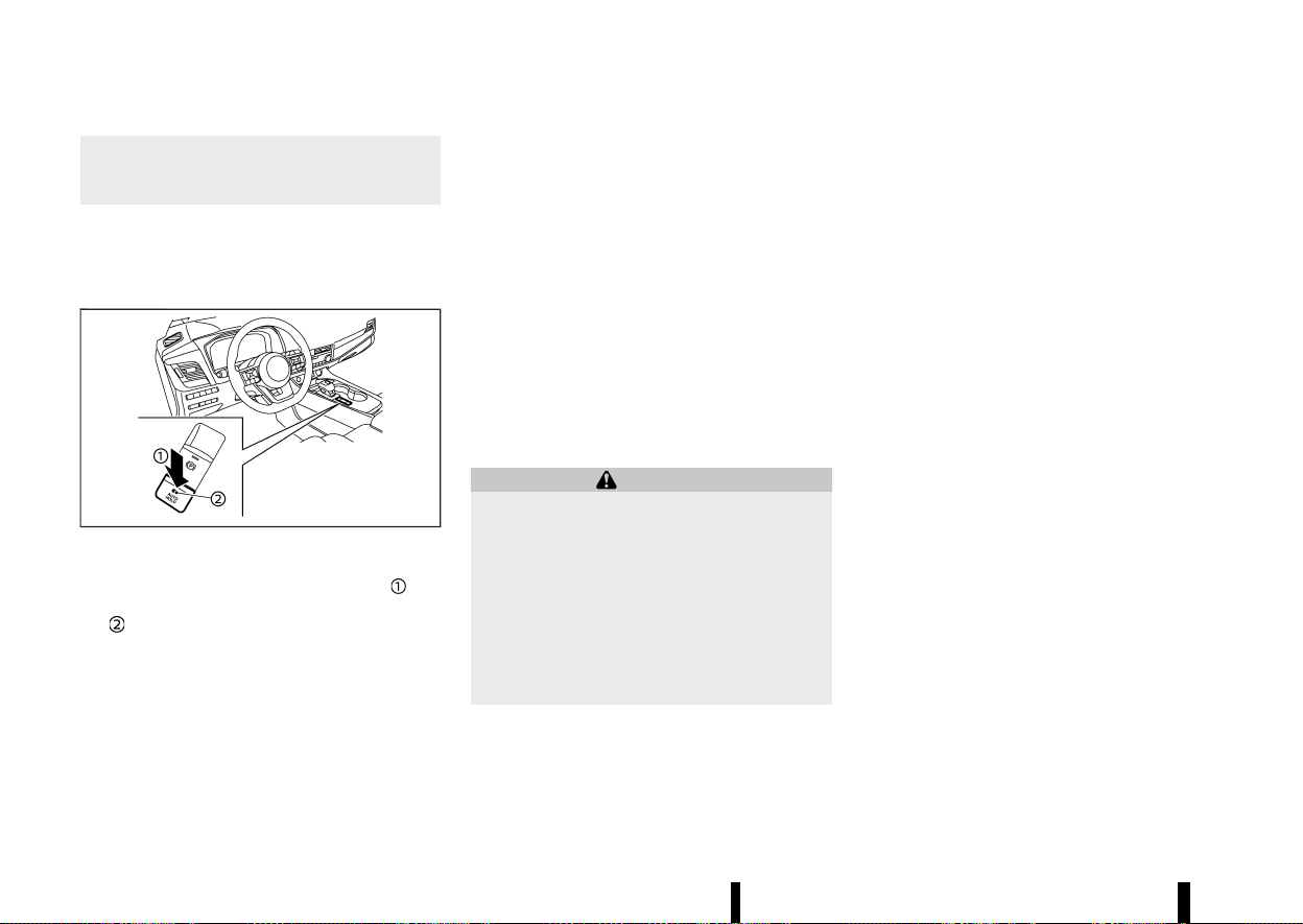
(178,1)
174 Pre-driving checks and adjustments
brake pedal first, then to turn off the
Automatic brake hold switch. This will
cancel the hold function.
HOW TO ACTIVATE/DEACTIVATE
AUTOMATIC BRAKE HOLD FUNCTION
MEVT33A1-98DE0533-F6F2-4287-B0EA-D377EA14525E
How to activate Automatic brake hold function
MEVT33A1-5375EA66-62BA-4E34-B343-14104AA944CC
MWAD0358X
1. With the ignition switch in the ON position,
push the automatic brake hold switch
. The
indicator light on Automatic brake hold switch
illuminates.
2. When Automatic brake hold function goes into
standby, Automatic brake hold indicator light
(white) illuminates.
To use Automatic brake hold function, the follow-
ing conditions need to be met.
* The driver’s seat belt is fastened.
* The electronic parking brake is released.
* The vehicle is not in the P (Park) position.
* The vehicle is not parked on a steep hill.
NOTE:
Automatic brake hold function retains the last
state until the driver changes the option even if
the ignition switch is turned off.
How to deactivate Automatic brake hold function
MEVT33A1-DF886425-9352-48BE-A1C5-CD462C296F29
While Automatic brake hold function is activated,
push Automatic brake hold switch to turn off
Automatic brake hold indicator light and deacti-
vate Automatic brake hold function. To deactivate
Automatic brake hold function while the braking
force has been maintained by Automatic brake
hold function, depress the brake pedal and push
Automatic brake hold switch.
WARNING
Make sure to firmly depress and hold the brake
pedal when turning off Automatic brake hold
function while the braking force is applied.
When Automatic brake hold function is deac-
tivated, the braking force will be released. This
could cause the vehicle to move or roll away
unexpectedly.
Failure to prevent the vehicle from rolling may
result in serious personal injury or property
damage.
HOW TO USE AUTOMATIC BRAKE HOLD
FUNCTION
MEVT33A1-FEECADFA-EE64-48EE-B82C-2D6C55F431DC
To maintain braking force automatically
MEVT33A1-8E9DC1C6-047A-4CEC-9E53-F1F55401C9B4
With Automatic brake hold function activated and
Automatic brake hold indicator light (white) illumi-
nated, depress the braking pedal to stop the
vehicle, and the indicator light (green) illuminates.
The braking force is automatically applied without
your foot depressed on the brake pedal. While the
braking force is maintained, Automatic brake hold
indicator light (green) illuminates.
Automatic brake hold indicator light (green) will
not illuminate if the brake pedal is not depressed
with sufficient force to hold the vehicle or is
released too quickly when the vehicle is stopped.
Confirm Automatic brake hold indicator light
(green) is illuminated before removing your foot
from the brake pedal.
To start the vehicle from a standstill
MEVT33A1-70CD7E5C-81E6-4285-9B51-30B8B6AC260E
With the vehicle not in the P (Park) or the N
(Neutral) position, depress the accelerator pedal
while the braking force is maintained. The braking
force will automatically be released to restart the
vehicle. Automatic brake hold indicator light
(white) illuminates and Automatic brake hold
returns to standby.
Parking
MEVT33A1-D77C0F0A-B129-43C4-8D4C-7B07FB9E2E11
When the vehicle is in the P (Park) position with the
braking force maintained by Automatic brake hold
function, the electronic parking brake will auto-
matically be applied and the braking force of

(179,1)
Automatic brake hold will be released. Automatic
brake hold indicator light turns off. When the
electronic parking brake is applied with the brak-
ing force maintained by Automatic brake hold
function, the braking force of Automatic brake
hold will be released. Automatic brake hold in-
dicator light turns off.
NOTE:
* Under the following conditions, the electro-
nic parking brake will automatically be
applied and the braking force of Automatic
brake hold will be released. Automatic brake
hold indicator light turns off.
— The braking force is applied by Automatic
brake hold function for 3 minutes or
longer.
— The vehicle is in the P (Park) position.
— Electronic parking brake is applied manu-
ally.
— The driver’s seat belt is unfastened.
— The driver’s door is opened.
— The ignition switch is placed in the “OFF”
position.
— A malfunction occurs in Automatic brake
hold function.
* When the vehicle stops, but the braking
force is not automatically applied, depress
the brake pedal firmly until Automatic brake
hold indicator light (green) illuminates.
* When the vehicle stops in a slope, depress
the brake pedal firmly until Automatic brake
hold indicator light (green) illuminates.
Pre-driving checks and adjustments 175

(180,1)
176 Pre-driving checks and adjustments
MEMO

(181,1)
4 Monitor, heater, air conditioner, audio and
phone systems
Apple CarPlay and Android Auto (where fitted) ................. 179
NissanConnect Owner’s Manual (where fitted) ................... 179
SAFETY INFORMATION ................................................................... 180
NAVIGATION (where fitted) ........................................................ 181
AUDIO OPERATION PRECAUTIONS ....................................... 182
HOW TO UPDATE MAP DATA (where fitted) ................. 182
UPDATING SYSTEM SOFTWARE (where fitted) ............ 182
REGULATORY INFORMATION .................................................... 182
TRADEMARKS ........................................................................................ 184
LICENSES .................................................................................................. 184
Safety precautions ..................................................................................... 185
Rear view monitor (where fitted) ................................................... 185
Rear view monitor system operation ............................... 186
How to read the displayed lines ........................................... 186
Difference between predictive and
actual distances ................................................................................. 186
How to park with predictive course lines ..................... 188
Rear view monitor settings ....................................................... 189
Rear view monitor system limitations ............................. 189
System maintenance ..................................................................... 190
Intelligent Around View Monitor (where fitted) .................. 191
Intelligent Around View Monitor
system operation .............................................................................. 192
Difference between predictive and
actual distances ................................................................................. 194
How to park with predictive course lines ....................... 196
How to switch the display ........................................................... 197
Adjusting the screen ........................................................................ 197
Intelligent Around View Monitor
system limitations .............................................................................. 198
System maintenance ....................................................................... 199
Moving Object Detection (MOD) (where fitted) ...................... 200
MOD system operation ................................................................... 201
Turning MOD on and off ............................................................... 202
MOD system limitations ................................................................. 202
System maintenance ....................................................................... 203
Vents ........................................................................................................................ 203
Centre vents ............................................................................................ 203
Side vents .................................................................................................. 203
Rear vents ................................................................................................. 204
Heater and air conditioner .................................................................... 204
Operating tips (for automatic air conditioner) ............ 204
Manual air conditioner and heater ....................................... 206
Automatic air conditioner (models without
rear control) ............................................................................................. 209
Automatic air conditioner (models with
rear control) ............................................................................................. 211
Servicing air conditioner ............................................................... 212
Audio system (where fitted) ................................................................. 213
Audio operation precautions ..................................................... 213

(182,1)
FM-AM radio with USB (Universal Serial Bus)
connection port .................................................................................. 218
USB (Universal Serial Bus) connection port ................. 224
Steering-wheel-mounted controls for audio .............. 225
USB device care .................................................................................. 225
Radio antenna ............................................................................................... 225
Car phone or CB radio
....
........................................................................ 226
Bluetooth® Hands-Free Phone System
(where fitted)
....
............................................................................................... 226
Regulatory information
....
............................................................ 227
Control buttons and microphone
....
................................... 227
Bluetooth® settings
....
..................................................................... 227
Using the system
....
.......................................................................... 229
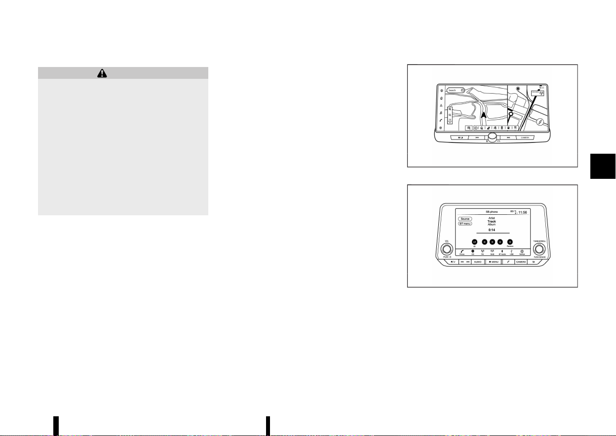
(183,1)
GUID-9764A25E-B549-431B-95DB-9981779011B8
WARNING
* Stop your vehicle in a safe location and
apply the parking brake before connecting
your mobile device to the vehicle or oper-
ating your connected mobile device for
setup.
* Laws in some jurisdictions may restrict the
use of some of the applications and
features, such as social networking and
texting. Check local regulations for any
requirements.
* If you are unable to devote full attention to
vehicle operation while using your mobile
device, pull off the road to a safe location
and stop your vehicle.
Apple CarPlay:
With Apple CarPlay, your in-vehicle system can be
used as a display and a controller for some of the
iPhone functions. Apple CarPlay features Siri which
enables operations via voice controls. Wireless
Apple CarPlay (where fitted) is also available for
certain iPhone models. Refer to the NissanConnect
Owner’s Manual and visit the Apple website for
information about the functions that are available
and other details.
NOTE:
To ensure efficient wireless charging (where
fitted) , do not use wireless Apple CarPlay and
wireless charging simultaneously for long peri-
ods. Use a USB connection in these circum-
stances.
Android Auto:
With Android Auto, your in-vehicle system can be
used as a display and a controller for some of your
Android phone functions. Android Auto supports
Talk to Google which enables operations via voice
controls. Refer to the NissanConnect Owner’s
Manual and visit the Android Auto website for
information about the functions that are available
and other details.
MEVT33A1-4DEABA82-7F30-4E18-A73C-377021F0EF62
MNAA2093
Type A
MNAA2011
Type B
For details, see the separately provided Nissan-
Connect Owner’s Manual.
* Online:
— TYPE A
Go to: https://uqr.to/16959
Or scan the QR code
Monitor, heater, air conditioner, audio and phone systems 179
Apple CarPlay AND Android
Auto (where fitted)
Apple CarPlay AND Android
Auto (where fitted)
NISSANCONNECT OWNER’S
MANUAL (where fitted)
NISSANCONNECT OWNER’S
MANUAL (where fitted)
(184,1)
180 Monitor, heater, air conditioner, audio and phone systems
WAE0858X
— TYPE B
Go to: https://uqr.to/1695g
Or scan the QR code
WAE0858X
* Printed version: Please contact your NISSAN
dealer or qualified workshop.
SAFETY INFORMATION
GUID-29474D0D-D22A-4B98-AFE3-4148EF853355
This system is primarily designed to help you
support pleasant driving as outlined in this man-
ual. However, you, the driver, must use the system
safely and properly. Information and the availabil-
ity of services may not always be up to date. The
system is not a substitute for safe, proper and legal
driving.
Before using the system, please read the following
safety information. Always use the system as
outlined in this manual.
WARNING
* To operate the system, first park the
vehicle in a safe location and set the
parking brake. Operating the system while
driving can distract the driver and may
result in a serious accident.
* Exercise extreme caution at all times so full
attention may be given to vehicle opera-
tion. If the system does not respond
immediately, please be patient and keep
your eyes on the road. Inattentive driving
may lead to a crash resulting in serious
injuries or death.
* Do not rely on route guidance (where
fitted) alone. Always be sure that all driving
manoeuvres are legal and safe in order to
avoid accidents.
* Do not disassemble or modify this system.
If you do, it may result in accidents, fire or
electrical shock.
* If you notice any foreign objects in the
system hardware, spill liquid on the sys-
tem or notice smoke or a smell coming
from it, stop using the system immediately
and it is recommended you contact a
NISSAN dealer or qualified workshop.
Ignoring such conditions may lead to
accidents, fire or electrical shock.
CAUTION
* Some jurisdictions may have laws limiting
the use of video screens while driving. Use
this system only where it is legal to do so.
* Extreme temperature conditions (below
−20°C (−4°F) and above 70°C (158°F) ) could
affect the performance of the system.
* The display screen may break if it is hit
with a hard or sharp object. If the display
screen breaks, do not touch it. Doing so
could result in an injury.
NOTE:
Do not keep the system running with the engine
stopped. Doing so may discharge the vehicle
battery (12V battery). When you use the system,
always keep the engine running.
Models with NissanConnect Services:
NissanConnect Services may not be available in
some regions. Completing the NissanConnect
Services registration is necessary to use Nissan-
Connect Services related functions.

(185,1)
Hands-free telephone control
GUID-9D380788-C282-48AF-8352-B9C64DDD05C6
WARNING
* Use a phone after stopping your vehicle in
a safe location. If you have to use a phone
while driving, exercise extreme caution at
all times so full attention may be given to
vehicle operation.
* If you find yourself unable to devote full
attention to vehicle operation while talking
on the phone, pull off the road to a safe
location and stop your vehicle before
doing so.
CAUTION
To avoid draining the vehicle battery (12V
battery), use a phone only after starting the
engine.
Hands-free text messaging assistant
GUID-9297D760-288A-44E6-8E3C-D7CC0BAEBEA6
WARNING
* Use the text messaging feature after
parking your vehicle in a safe location. If
you have to use the feature while driving,
exercise extreme caution at all times so full
attention may be given to vehicle opera-
tion.
* Laws in some jurisdictions may restrict the
use of “Text-to-Speech.” Check local reg-
ulations before using this feature.
* Laws in some jurisdictions may restrict the
use of some of the applications and
features, such as social networking and
texting. Check local regulations for any
requirements.
* If you are unable to devote full attention to
vehicle operation while using the text
messaging feature, pull off the road to a
safe location and stop your vehicle.
CAUTION
This feature is disabled if the connected device
does not support it. See the phone’s Owner’s
Manual for details and instructions.
Liquid crystal display
GUID-A70F8DBC-AB6A-4B71-B8CC-41217B1A2F1E
The display on this unit is a liquid crystal display
and should be handled with care.
WARNING
Never disassemble the display. Some parts
utilise extremely high voltage. Touching them
may result in serious personal injury.
Maintenance of display:
To clean the display screen, use a dry, soft cloth. If
additional cleaning is necessary, use a small
amount of neutral detergent with a soft cloth.
Never spray the screen with water or detergent.
Dampen the cloth first, then wipe the screen.
CAUTION
* To clean the display, never use a rough
cloth, alcohol, benzine, thinner or any kind
of solvent or paper towel with a chemical
cleaning agent. They will scratch or dete-
riorate the panel.
* Do not splash any liquid, such as water or
car fragrance, on the display. Contact with
liquid will cause the system to malfunction.
NAVIGATION (where fitted)
GUID-98D2D2EC-5D05-44A9-98AE-DB9B851F4455
The navigation system is primarily designed to
help you reach your destination. However, you, the
driver, must use the system safely and properly.
Information concerning road conditions, traffic
signs and the availability of services may not
always be up to date. The system is not a
substitute for safe, proper, and legal driving.
WARNING
* Do not rely on route guidance alone. Al-
ways be sure that all driving manoeuvres
are legal and safe in order to avoid
accidents.
* Always stop the vehicle in a safe location
before modifying the route conditions.
Modifying the route conditions while driv-
ing may cause an accident.
* The navigation system’s visual and voice
guidance is for reference purposes only.
The contents of the guidance may be
inappropriate depending on the situation.
* Follow all traffic regulations when driving
along the suggested route (e.g. one-way
traffic).
Monitor, heater, air conditioner, audio and phone systems 181
(186,1)
182 Monitor, heater, air conditioner, audio and phone systems
AUDIO OPERATION PRECAUTIONS
GUID-CE8784EF-F738-4DCC-8E6A-2CBC684238D1
CAUTION
* Operate the audio system only when the
vehicle engineis running. Operating the
audio system for extended periods of time
with the engine turned off can discharge
the vehicle battery (12V battery).
* Do not allow the system to get wet.
Excessive moisture such as spilled liquids
may cause the system to malfunction.
HOW TO UPDATE MAP DATA (where
fitted)
GUID-4DC99133-6619-4DC7-B180-9128AB3DEE29
WARNING
TO AVOID RISK OF DEATH OR SERIOUS PERSO-
NAL INJURY WHEN UPDATING THE MAP SOFT-
WARE:
If you choose to park the vehicle within range
of a Wi-Fi connection (where fitted) or a TCU
(Telematics Control Unit) (where fitted), park
the vehicle in a secure, safe, well-ventilated
location that is open to the air. During the
update process, if you choose to park your
vehicle, it should be kept in a well ventilated
area to avoid exposure to carbon monoxide.
Do not breathe exhaust gases; they contain
colourless and odourless carbon monoxide.
Carbon monoxide is dangerous. It can cause
unconsciousness or death.
UPDATING SYSTEM SOFTWARE (where
fitted)
GUID-22B4B274-1406-437D-B6DB-2549A5C2DFCE
WARNING
TO AVOID RISK OF DEATH OR SERIOUS PERSO-
NAL INJURY WHEN UPDATING THE SYSTEM
SOFTWARE:
If you choose to park the vehicle within range
of a Wi-Fi connection (where fitted), park the
vehicle in a secure, safe, well-ventilated loca-
tion that is open to the air. During the update
process, if you choose to park your vehicle, it
should be kept in a well ventilated area to
avoid exposure to carbon monoxide. Do not
breathe exhaust gases; they contain colourless
and odourless carbon monoxide. Carbon mon-
oxide is dangerous. It can cause unconscious-
ness or death.
How to update from the system menu
GUID-2008300B-C395-45EC-9DF5-FD42F1220332
WARNING
To operate the system for software update,
first park the vehicle in a safe location.
REGULATORY INFORMATION
GUID-A8834B74-590A-46BB-8CE2-813A76C350BA
Radio approval number and information
GUID-D3A68A10-C105-4066-B59E-7CE14882D7EE
For Europe:
Type A:
Hereby, Robert Bosch GmbH declares that the
radio equipment type AIVI2SBXM is in compliance
with Directive 2014/53/EU.
The full text of the EU declaration of conformity is
available at the following internet address:
https://eu-doc.bosch.com
MNSY0105
Hereby, Robert Bosch GmbH declares that the
radio equipment type AIVI2SBXM is in compliance
with of Radio Equipment Regulations 2017.
MWAJ0410X
Frequency Band
2400 MHz - 2480 MHz
5490 MHz - 5600 MHz
5650 MHz - 5710 MHz ≤ 100 mW
5735 MHz - 5835 MHz ≤ 25 mW
Radiated Power [EIRP]
Bluetooth < 10 mW
WLAN < 100 mW
Hints/Restrictions
Internal Antenna
Internal antenna not accessible by user. Any
change by the user will violate the legal approval
of this product.
Type B:
Hereby, Robert Bosch GmbH declares that the
(187,1)
radio equipment type AIVIP33A0 is in compliance
with Directive 2014/53/EU.
The full text of the EU declaration of conformity is
available at the following internet address:
https://eu-doc.bosch.com
MNSY0105
Hereby, Robert Bosch GmbH declares that the
radio equipment type AIVIP33A0 is in compliance
with of Radio Equipment Regulations 2017.
MWAJ0410X
Frequency Band
2400 MHz - 2480 MHz
Radiated Power [EIRP]
Bluetooth < 10 mW
WLAN < 100 mW
Hints/Restrictions
Internal Antenna
Internal antenna not accessible by user.Any
change by the user will violate the legal approval
of this product.
For Ukraine:
Type A:
MPHB0263XZ
PBH0015X
MNAVI0008
Type B:
MNAVI0007
PBH0015X
MNAVI0008
Monitor, heater, air conditioner, audio and phone systems 183

(188,1)
184 Monitor, heater, air conditioner, audio and phone systems
TRADEMARKS
GUID-F6151569-E340-4B7C-A3AB-0D87613AE5BD
MPBA0032X
M5GD0030X
Apple, iPhone, iPod, and iPod touch are trademarks
of Apple Inc., registered in the U.S. and other
countries. Apple CarPlay is a trademark of Apple
Inc. Use of the Apple CarPlay logo means that a
vehicle user interface meets Apple performance
standards. Apple is not responsible for the opera-
tion of this vehicle or its compliance with safety
and regulatory standards. Please note that the use
of this product with iPhone or iPod may affect
wireless performance.
M5GA0023X
Bluetooth® is a trademark owned by Bluetooth SIG,
Inc. and licensed to Robert Bosch GmbH.
M5GA0247X
Music recognition technology and related data are
provided by Gracenote®. Gracenote is the industry
standard in music recognition technology and
related content delivery. For more information,
visit www.gracenote.com. Music related data from
Gracenote, Inc., copyright © 2000 to present
Gracenote. Gracenote Software, copyright ©
2000 to present Gracenote.
One or more patents owned by Gracenote apply to
this product and service. See the Gracenote
website for a nonexhaustive list of applicable
Gracenote patents. Gracenote, the Gracenote logo
and logotype are either a registered trademark or
a trademark of Gracenote, Inc. in the United States
and/or other countries.
App Store
Apple and the Apple logo are trademarks of Apple
Inc., registered in the U.S. and other countries. App
Store is a service mark of Apple Inc.
Siri
Siri is a trademark of Apple Inc., registered in the
U.S. and other countries.
Google/Android/Google Play/Android Auto
Google, Android, Google Play, Android Auto, and
other marks are trademarks of Google LLC.
LICENSES
GUID-2553DC8F-2A05-4701-BA43-587D28B2FEDC
SOFTWARE LICENSES
GUID-465916F7-1802-4CEA-8AB7-C04167098799
Open Source Software Licences
http://oss.bosch-cm.com/nissan.html
Telematics Control unit (TCU) (where fitted)
GUID-E204BCA1-A3AA-40A3-AF44-ED2E49D56394
http://opensourceautomotive.com/IC/
tZ7T3eE6AiV4
or
https://www.oss-valeo.com/nissan/default. html
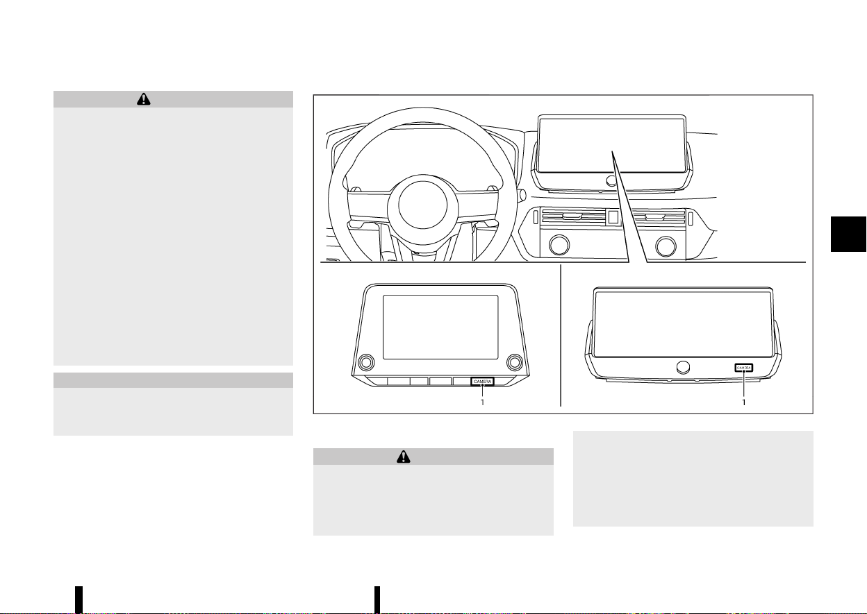
(189,1)
MEVT33A1-1F19A411-4DF6-4FA2-B2EA-F595247A81C7
WARNING
* Do not adjust the display controls, heater
and air conditioner controls or audio con-
trols while driving so that full attention
may be given to vehicle operation.
* If you noticed any foreign objects entering
the system hardware, spilled liquid on the
system, or noticed smoke or fumes coming
out from the system, or any other unusual
operation is observed, stop using the
system immediately and contact the near-
est NISSAN dealer or qualified workshop.
Ignoring such conditions may lead to an
accident, fire or electric shock.
* Do not disassemble or modify this system.
If you do, it may lead to an accident, fire, or
electric shock.
* Park the vehicle in a safe location and
apply the parking brake to view images on
the front centre display screen.
CAUTION
Do not use the system when the engine is not
running for extended periods of time to pre-
vent battery discharge.
MEVT33A1-E32CDD38-B834-4D2E-9F15-7E5C88FAB9C5
MWAE0877X
1. <CAMERA> button
WARNING
* Failure to follow the warnings and instruc-
tions for proper use of the rear view
monitor could result in serious injury or
death.
* The rear view monitor is a convenience
feature and is not a substitute for proper
reversing. Always turn and look out the
windows, and check mirrors to be sure that
it is safe to move before operating the
vehicle. Always reverse slowly.
* The system is designed as an aid to the
driver in showing large stationary objects
Monitor, heater, air conditioner, audio and phone systems 185
SAFETY PRECAUTIONS
SAFETY PRECAUTIONS
REAR VIEW MONITOR (where fitted)
REAR VIEW MONITOR (where fitted)
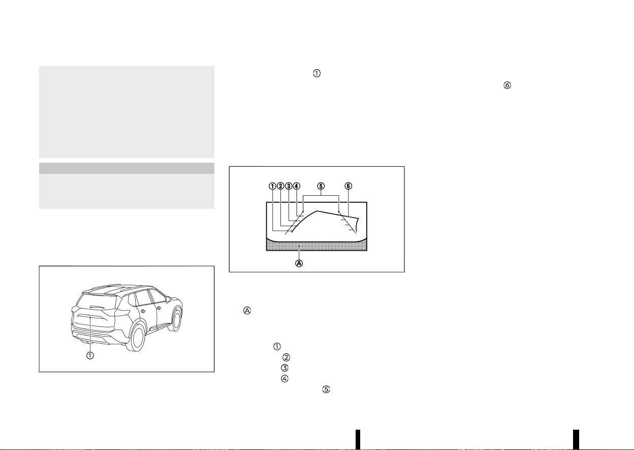
(190,1)
186 Monitor, heater, air conditioner, audio and phone systems
directly behind the vehicle, to help avoid
damaging the vehicle.
* The distance guide line and the vehicle
width line should be used as a reference
only when the vehicle is on a level paved
surface. The distance viewed on the moni-
tor is for reference only and may be
different than the actual distance between
the vehicle and displayed objects.
CAUTION
There is a transparent cover over the camera
lens. Do not scratch the cover when cleaning
dirt or snow from it.
The rear view monitor system automatically shows
a rear view of the vehicle when the shift lever is
placed in the "R" (Reverse) position.
The radio can still be heard while the rear view
monitor is active.
MWAE0335X
To display the rear view, the rear view monitor
system uses a camera
located just above the
vehicle’s number plate.
REAR VIEW MONITOR SYSTEM OPERA-
TION
MEVT33A1-6D91C4EA-6F91-4864-8872-367E41A22325
When the ignition switch is placed in the "ON"
position, move the shift lever to the "R" (Reverse)
position to operate the rear view monitor.
HOW TO READ THE DISPLAYED LINES
MEVT33A1-D20F3487-0821-4A93-857D-7074E42B5DCE
MSAA1896
Guiding lines which indicate the vehicle width and
distances to objects with reference to the bumper
line
are displayed on the monitor.
Distance guide lines:
Indicate distances from the vehicle body.
* Red line
: approximately 0.5 m (1.5 ft)
* Yellow line
: approximately 1 m (3 ft)
* Green line
: approximately 2 m (7 ft)
* Green line
: approximately 3 m (10 ft)
Vehicle width guide lines
:
Indicate the vehicle width when reversing.
Predictive course lines
:
Indicate the predictive course when reversing. The
predictive course lines will be displayed on the
monitor when the shift lever is in the "R" (Reverse)
position and if the steering wheel is turned. The
predictive course lines will move depending on
how much the steering wheel is turned and will
not be displayed while the steering wheel is in the
straight ahead position.
The vehicle width guide lines and the width of the
predictive course lines are wider than the actual
width and course.
DIFFERENCE BETWEEN PREDICTIVE AND
ACTUAL DISTANCES
MEVT33A1-B0CBD45C-C473-4E14-9E08-0ADAA810B264
The displayed guide lines and their locations on
the ground are for approximate reference only.
Objects on uphill or downhill surfaces or projecting
objects will be actually located at distances
different from those displayed in the monitor
relative to the guide lines (refer to illustrations).
When in doubt, turn around and view the objects
as you are reversing, or park and exit the vehicle to
view the positioning of objects behind the vehicle.
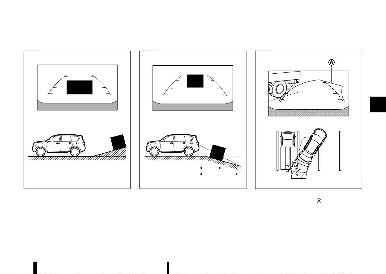
(191,1)
Reversing on a steep uphill
MEVT33A1-3783308A-CAFF-4760-876A-18418EFB37C2
MWAE0673X
When reversing the vehicle up a hill, the distance
guide lines and the vehicle width guide lines are
shown closer than the actual distance. Note that
any object on the hill is farther than it appears on
the monitor.
Reversing on a steep downhill
MEVT33A1-1D7099A3-99D9-4FDF-96DD-BAF43C75A3DD
MWAE0674X
When reversing the vehicle down a hill, the
distance guide lines and the vehicle width guide
lines are shown farther than the actual distance.
Note that any object on the hill is closer than it
appears on the monitor.
Reversing near a projecting object
MEVT33A1-67E6A09C-934D-48C8-8E38-8404AC78A624
MSAA1923
The predictive course lines do not touch the
object in the display. However, the vehicle may hit
the object if it projects over the actual reversing
course.
Monitor, heater, air conditioner, audio and phone systems 187
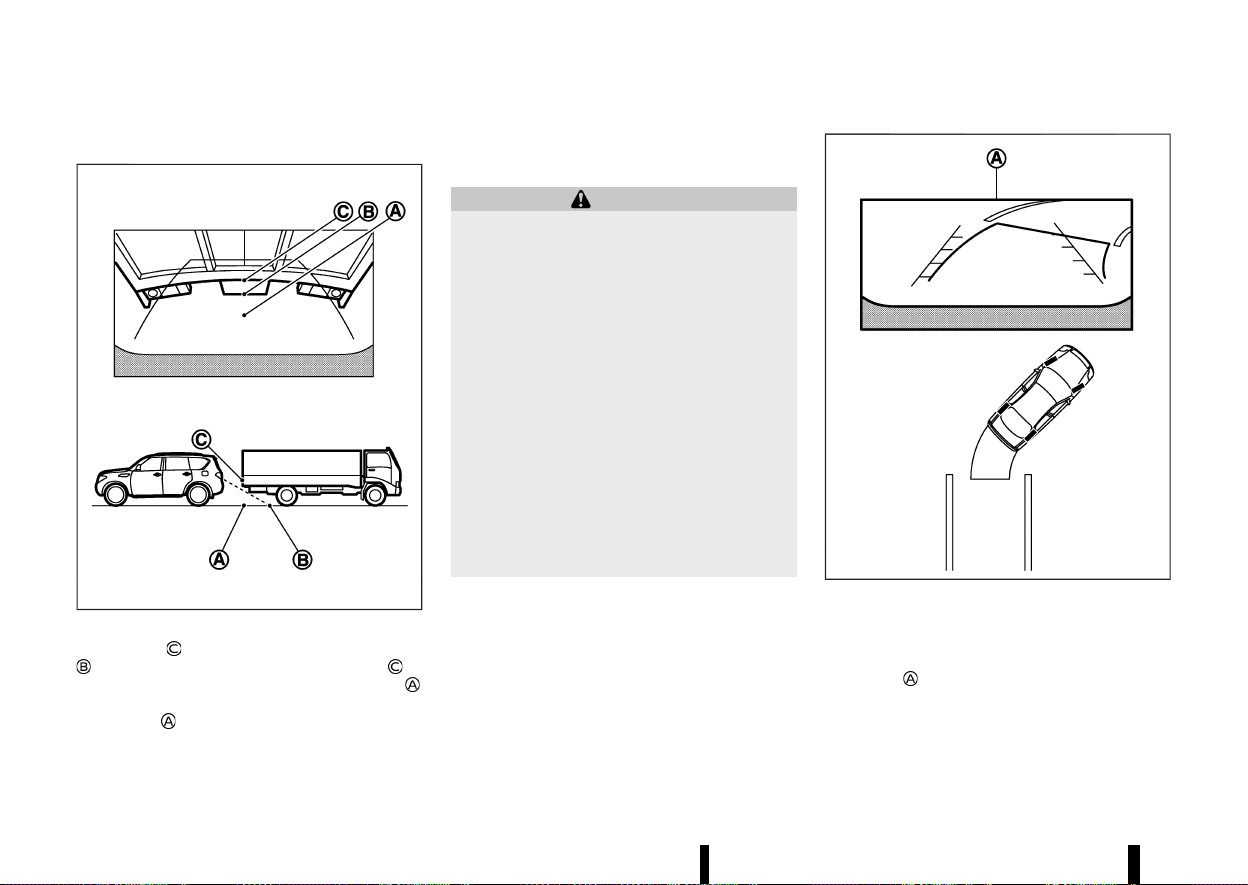
(192,1)
188 Monitor, heater, air conditioner, audio and phone systems
Reversing behind a projecting object
MEVT33A1-D4955A6B-8211-4D34-BCDC-F3F2AA07FD3E
MJVH1216X
The position is shown farther than the position
in the display. However, the position is
actually at the same distance as the position
.
The vehicle may hit the object when reversing to
the position
if the object projects over the actual
reversing course.
HOW TO PARK WITH PREDICTIVE
COURSE LINES
MEVT33A1-91FD33BD-6BB3-4461-8DFE-1B7B9DA28285
WARNING
* If the tyres are replaced with different
sized tyres, the predictive course lines
may be displayed incorrectly.
* On a snow-covered or slippery road, there
may be a difference between the predic-
tive course line and the actual course line.
* If the battery is disconnected or becomes
discharged, the predictive course lines
may be displayed incorrectly. If this occurs,
please perform the following procedures:
— Turn the steering wheel from lock to
lock while the engine is running.
— Drive the vehicle on a straight road for
more than 5 minutes.
* When the steering wheel is turned with the
ignition switch in the "ON" position, the
predictive course lines may be displayed
incorrectly.
MSAA1897
1. Visually check that the parking space is safe
before parking your vehicle.
2. The rear view of the vehicle is displayed on the
screen
when the shift lever is moved to the
"R" (Reverse) position.
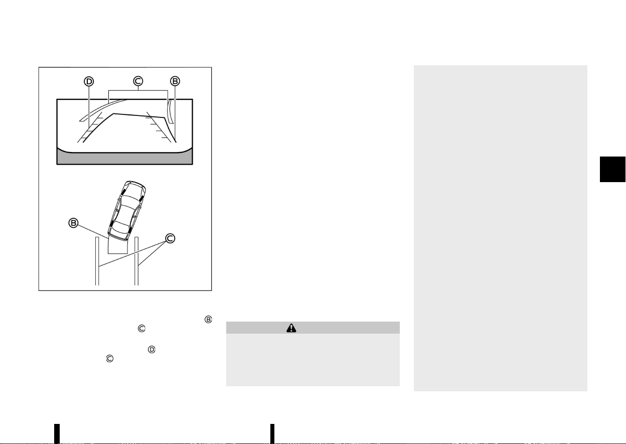
(193,1)
MWAE0465X
3. Slowly reverse the vehicle adjusting the steer-
ing wheel so that the predictive course lines
enter the parking space .
4. Manoeuvre the steering wheel to make the
vehicle width guide lines
parallel to the
parking space
while referring to the pre-
dictive course lines.
5. When the vehicle is parked in the space
completely, place the shift position in the "P"
(Park) position and apply the parking brake.
REAR VIEW MONITOR SETTINGS
MEVT33A1-54416AD3-192F-4BD6-9F2D-D870FB593E1B
To set up the rear view monitor, push the
<CAMERA> button while the shift lever is out of
the "R" (Reverse) position to display the Camera
Setting screen.
Available setting items:
* [Predictive course line]
Predictive course lines can be turned on/off.
* [Display setting]
The brightness, contrast, tint, colour and black
level can be adjusted.
NOTE:
Do not adjust any of the display settings of the
rear view monitor while the vehicle is moving.
Make sure the parking brake is firmly applied.
The predictive course lines can also be turned on
and off by pushing the <CAMERA> button while the
shift lever is in the "R" (Reverse) position.
REAR VIEW MONITOR SYSTEM LIMITA-
TIONS
MEVT33A1-EFFF2C63-07DF-4C45-BC34-87E0A099AC03
WARNING
Listed below are the system limitations for rear
view monitor. Failure to operate the vehicle in
accordance with these system limitations
could result in serious injury or death.
* The system cannot completely eliminate
blind spots and may not show every
object.
* Underneath the bumper and the corner
areas of the bumper cannot be viewed on
the rear view monitor because of its
monitoring range limitation. The system
will not show small objects below the
bumper, and may not show objects close
to the bumper or on the ground.
* Objects viewed in the rear view monitor
differ from actual distance because a
wide-angle lens is used.
* Objects in the rear view monitor will
appear visually opposite compared to
when viewed in the rear view and outside
rearview mirrors.
* Use the displayed lines as a reference. The
lines are highly affected by the number of
occupants, fuel level, vehicle position, road
conditions and road grade.
* Make sure that the back door is securely
closed when reversing.
* Do not put anything on the rear view
camera. The rear view camera is installed
above the number plate.
* When washing the vehicle with high-pres-
sure water, be sure not to spray it around
the camera. Otherwise, water may enter
the camera unit causing water condensa-
tion on the lens, a malfunction, fire or an
electric shock.
* Do not strike the camera. It is a precision
instrument. Otherwise, it may malfunction
Monitor, heater, air conditioner, audio and phone systems 189
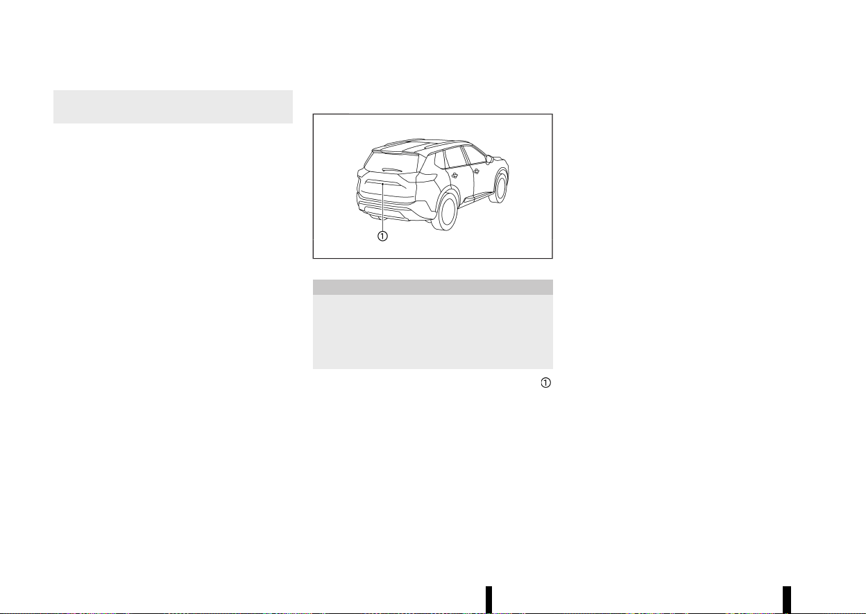
(194,1)
190 Monitor, heater, air conditioner, audio and phone systems
or cause damage resulting in a fire or an
electric shock.
The following are operating limitations and do not
represent a system malfunction:
* When the temperature is extremely high or
low, the screen may not clearly display objects.
* When strong light directly shines on the
camera, objects may not be displayed clearly.
* Vertical lines may be seen in objects on the
screen. This is due to strong reflected light
from the bumper.
* The screen may flicker under fluorescent light.
* The colours of objects on the rear view
monitor may differ somewhat from the actual
colour of objects.
* Objects on the monitor may not be clear in a
dark environment.
* There may be a delay when switching be-
tween views.
* If dirt, rain or snow accumulates on the
camera, the rear view monitor may not display
objects clearly. Clean the camera.
* Do not use wax on the camera lens. Wipe off
any wax with a clean cloth dampened with a
diluted mild cleaning agent, then wipe with a
dry cloth.
SYSTEM MAINTENANCE
MEVT33A1-A02CC587-5E86-43E2-BA3D-983BBBDAD052
MWAE0335X
CAUTION
* Do not use alcohol, benzine or thinner to
clean the camera. This will cause disco-
loration.
* Do not damage the camera as the monitor
screen may be adversely affected.
If dirt, rain or snow accumulates on the camera
,
rear view monitor may not display objects clearly.
Clean the camera by wiping it with a cloth
dampened with a diluted mild cleaning agent
and then wiping it with a dry cloth.
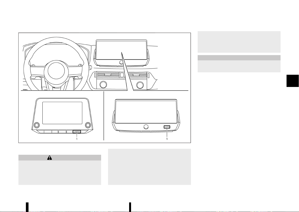
(195,1)
MEVT33A1-F8C01C15-8078-4B3F-B98A-3557D53F791C
MWAE0877X
1. <CAMERA> button
WARNING
* Failure to follow the warnings and instruc-
tions for the proper use of the Intelligent
Around View Monitor system could result
in serious injury or death.
* The Intelligent Around View Monitor is a
convenience feature and is not a substi-
tute for proper vehicle operation because
it has areas where objects cannot be
viewed. The four corners of the vehicle in
particular, are areas where objects do not
always appear in the bird’s-eye, front, or
rear views. Always check your surround-
ings to be sure that it is safe to move
before operating the vehicle. Always oper-
ate the vehicle slowly.
* The driver is always responsible for safety
during parking and other manoeuvres.
CAUTION
Do not scratch the lens when cleaning dirt or
snow from the front of the camera.
The Intelligent Around View Monitor system is
designed as an aid to the driver in situations such
as slot parking or parallel parking.
The monitor displays various views of the position
of the vehicle in a split screen format. Not all views
are available at all times.
Available views:
* Front view
A view of the front of the vehicle
* Rear view
A view of the rear of the vehicle
* Bird’s-eye view
The surrounding view of the vehicle from
above
* Front-side view
The view around and ahead of the front
passenger’s side wheel
* Front-wide view
A wider area view of the front view
* Rear-wide view
A wider area view of the rear view
Monitor, heater, air conditioner, audio and phone systems 191
INTELLIGENT AROUND VIEW
MONITOR (where fitted)
INTELLIGENT AROUND VIEW MONITOR (where fitted)
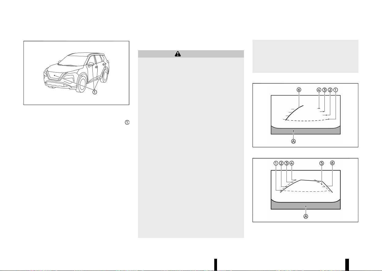
(196,1)
192 Monitor, heater, air conditioner, audio and phone systems
MWAE0360X
To display the multiple views, the Intelligent
Around View Monitor system uses cameras
located on the front grille, on the vehicle’s outside
rearview mirrors and one just above the vehicle’s
rear number plate.
INTELLIGENT AROUND VIEW MONITOR
SYSTEM OPERATION
MEVT33A1-36FA0286-A839-4423-9E7B-9BE407EEC3A8
When the ignition switch is placed in the "ON"
position, push the <CAMERA> button on the
instrument panel or move the shift lever to the
"R" (Reverse) position to operate the Intelligent
Around View Monitor.
The screen displayed on the Intelligent Around
View Monitor will automatically return to the
previous screen 3 minutes after the <CAMERA>
button has been pushed with the shift lever in a
position other than the "R" (Reverse) position.
Available views
MEVT33A1-7572CB5C-AACC-45EB-97C2-D9FFC5DFBA77
WARNING
* The distance guide lines and the vehicle
width guide lines should be used as a
reference only when the vehicle is on a
paved, level surface. The apparent dis-
tance viewed on the monitor may be
different than the actual distance between
the vehicle and displayed objects.
* Use the displayed lines and the bird’s-eye
view as a reference. The lines and the
bird’s-eye view are greatly affected by the
number of occupants, fuel level, vehicle
position, road condition and road grade.
* If the tyres are replaced with different
sized tyres, the predictive course lines
and the bird’s-eye view may be displayed
incorrectly.
* When driving the vehicle up a hill, objects
viewed in the monitor are farther than they
appear. When driving the vehicle down a
hill, objects viewed in the monitor are
closer than they appear.
* Objects in the rear view will appear visually
opposite compared to when viewed in the
rear view and outside rearview mirrors.
* Use the mirrors or actually look to properly
judge distances to other objects.
* The distance between objects viewed in
the rear view differs from actual distance
because a wide-angle lens is used.
* On a snow-covered or slippery road, there
may be a difference between the predic-
tive course line and the actual course line.
* The vehicle width and predictive course
lines are wider than the actual width and
course.
Front and rear view:
MWAE0538X
Front view
MWAE0883X
Rear view (example)
Guiding lines that indicate the approximate vehicle
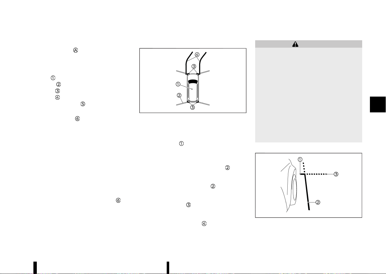
(197,1)
width and distances to objects with reference to
the vehicle body line
, are displayed on the
monitor.
Distance guide lines:
Indicate distances from the vehicle body.
* Red line
: approximately 0.5 m (1.5 ft)
* Yellow line
: approximately 1 m (3 ft)
* Green line
: approximately 2 m (7 ft)
* Green line
: approximately 3 m (10 ft)
Vehicle width guide lines
:
Indicate the vehicle width.
Predictive course lines
:
Indicate the predictive course when operating the
vehicle. The predictive course lines will move
depending on how much the steering wheel is
turned. The predictive course lines in the rear view
will not be displayed while the steering wheel is in
the straight ahead position.
The front view will not be displayed when the
vehicle speed is above 10 km/h (6 MPH).
NOTE:
When the monitor displays the front view and
the steering wheel turns about 90 degrees or
less from the straight ahead position, both the
right and left predictive course lines
are
displayed. When the steering wheel turns about
90 degrees or more, the predictive course line is
displayed only on the opposite side of the turn.
Bird’s-eye view:
MWAE0530X
The bird’s-eye view shows the overhead view of
the vehicle which helps confirm the vehicle posi-
tion and the predictive course to a parking space.
The vehicle icon
shows the position of the
vehicle. Note that the distance between objects
viewed in the bird’s-eye view differs from the
actual distance.
The areas between the camera views
(where
fitted) are indicated in black.
After the ignition switch is placed in the ON
position, the non-viewable area
(where fitted)
is highlighted in yellow for a few seconds after the
bird’s-eye view is displayed.
The amber markers
are displayed when the
parking sensor (sonar) is turned off or the parking
sensor (sonar) is not available at the corner.
The predictive course lines
indicate the pre-
dicted course when operating the vehicle.
WARNING
* Objects in the bird’s-eye view will appear
farther than the actual distance.
* Tall objects, such as a kerb or vehicle, may
be misaligned or not displayed at the seam
of the views.
* Objects that are above the camera cannot
be displayed.
* The view for the bird’s-eye view may be
misaligned when the camera position al-
ters.
* A line on the ground may be misaligned
and is not seen as being straight at the
seam of the views. The misalignment will
increase as the line proceeds away from
the vehicle.
Front-side view:
MWAE0501X
The screen layout in the illustration is for the Left-
Monitor, heater, air conditioner, audio and phone systems 193
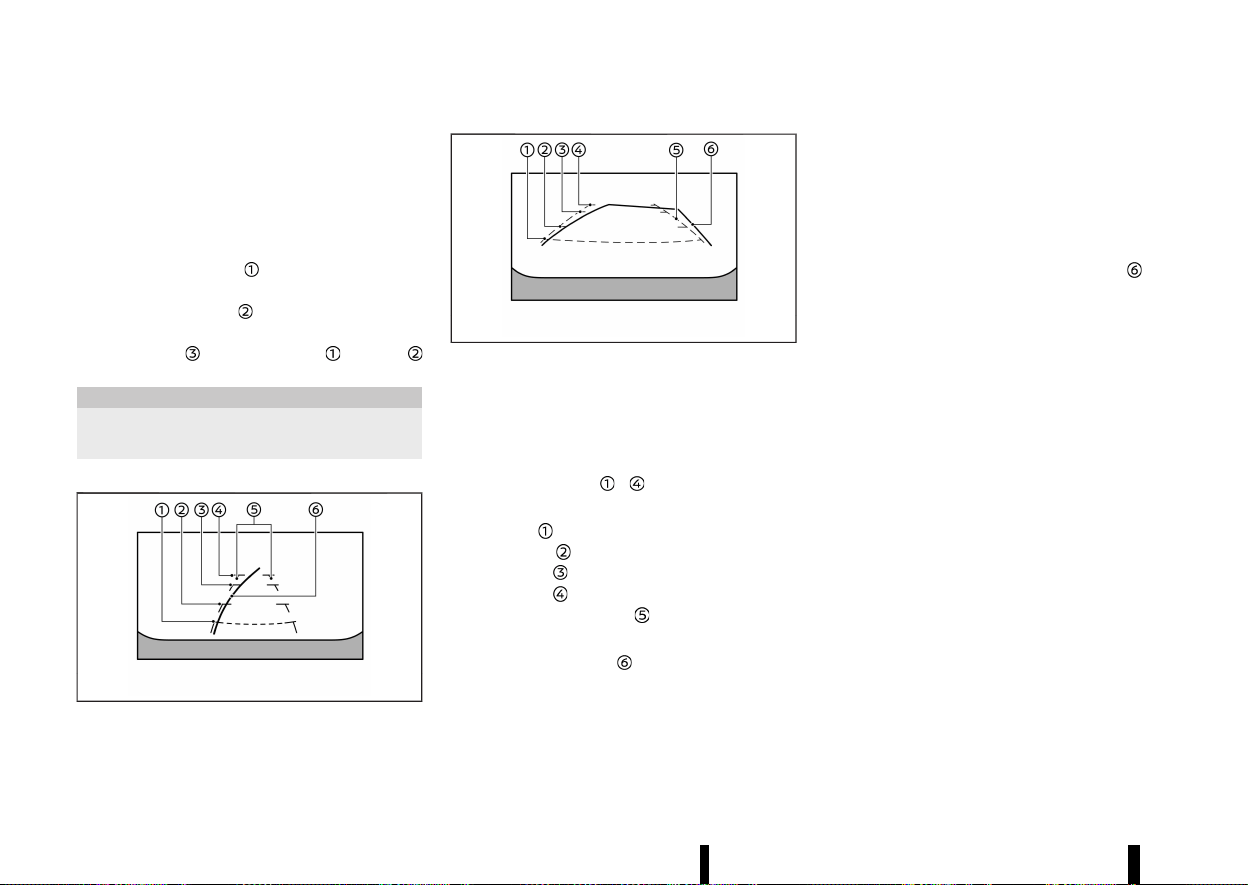
(198,1)
194 Monitor, heater, air conditioner, audio and phone systems
Hand Drive (LHD) model. For the Right-Hand Drive
(RHD) model, the screen layout will be opposite.
Guiding lines:
Guiding lines that indicate the approximate width
and the front end of the vehicle are displayed on
the monitor.
The front-of-vehicle line
shows the front part of
the vehicle.
The side-of-vehicle line
shows the vehicle width
including the outside rearview mirrors.
The extensions
of both the front and side
lines are shown with a green dotted line.
CAUTION
The turn signal light may look like the side-of-
vehicle line. This is not a malfunction.
Front-wide/rear-wide view:
MWAE0540X
Front-wide view
MWAE0885X
Rear-wide view
While the front view/rear view shows a normal
view on the split screens, the front-wide view/rear-
wide view shows a wider area on the entire screen
and allows checking of the blind corners on the
right and left sides.
Distance guide lines
- :
Indicate distances from the vehicle body.
* Red line
: approximately 0.5 m (1.5 ft)
* Yellow line
: approximately 1 m (3 ft)
* Green line
: approximately 2 m (7 ft)
* Green line
: approximately 3 m (10 ft)
Vehicle width guide lines
:
Indicate the approximate vehicle width.
Predictive course lines
:
Indicate the predictive course when operating the
vehicle. The predictive course lines will move
depending on how much the steering wheel is
turned. The predictive course lines in the rear-wide
view will not be displayed while the steering wheel
is in the straight ahead position.
The front-wide view will not be displayed when the
vehicle speed is above 10 km/h (6 MPH).
NOTE:
When the monitor displays the front-wide view
and the steering wheel turns about 90 degrees
or less from the straight ahead position, both
the right and left predictive course lines
are
displayed. When the steering wheel turns about
90 degrees or more, the predictive course line is
displayed only on the opposite side of the turn.
DIFFERENCE BETWEEN PREDICTIVE AND
ACTUAL DISTANCES
MEVT33A1-B6ACF5C4-134C-4B68-A0ED-CBDAFF972849
The displayed guide lines and their locations on
the ground are for approximate reference only.
Objects on uphill or downhill surfaces or projecting
objects will be actually located at distances
different from those displayed in the monitor
relative to the guide lines (refer to illustrations).
When in doubt, turn around and view the objects
as you are reversing, or park and exit the vehicle to
view the positioning of objects behind the vehicle.
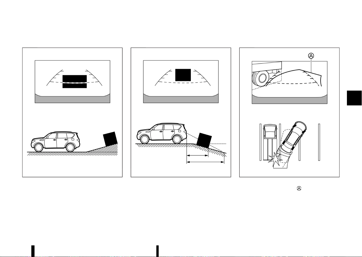
(199,1)
Reversing on a steep uphill
MEVT33A1-17FCDC12-83E2-468E-940E-597F3634AF48
MWAE0677X
When reversing the vehicle up a hill, the distance
guide lines and the vehicle width guide lines are
shown closer than the actual distance. Note that
any object on the hill is farther than it appears on
the monitor.
Reversing on a steep downhill
MEVT33A1-73B34D26-17C5-4A7F-9EFF-7D8619E78427
MWAE0678X
When reversing the vehicle down a hill, the
distance guide lines and the vehicle width guide
lines are shown farther than the actual distance.
Note that any object on the hill is closer than it
appears on the monitor.
Reversing near a projecting object
MEVT33A1-176E7FB2-9BF2-4A2B-BE18-B2CF54F579D1
MWAE0679X
The predictive course lines do not touch the
object in the display. However, the vehicle may hit
the object if it projects over the actual reversing
course.
Monitor, heater, air conditioner, audio and phone systems 195

(200,1)
196 Monitor, heater, air conditioner, audio and phone systems
Reversing behind a projecting object
MEVT33A1-DB1A3D70-210D-412E-9199-F5738F08FA04
MJVH1216X
The position is shown farther than the position
in the display. However, the position is
actually at the same distance as the position
.
The vehicle may hit the object when reversing to
the position
if the object projects over the actual
moving course.
HOW TO PARK WITH PREDICTIVE
COURSE LINES
MEVT33A1-A10621F6-2E6A-4A3D-AF6B-7DEE9A794969
WARNING
* If the tyres are replaced with different
sized tyres, the predictive course lines
may be displayed incorrectly.
* On a snow-covered or slippery road, there
may be a difference between the predic-
tive course line and the actual course line.
* If the battery is disconnected or becomes
discharged, the predictive course lines
may be displayed incorrectly. If this occurs,
please perform the following procedures:
— Turn the steering wheel from lock to
lock while the engine is running.
— Drive the vehicle on a straight road for
more than 5 minutes.
* When the steering wheel is turned with the
ignition switch in the "ON" position, the
predictive course lines may be displayed
incorrectly.
MWAE0680X
1. Visually check that the parking space is safe
before parking your vehicle.
2. The rear view of the vehicle is displayed on the
screen
when the shift lever is moved to the
"R" (Reverse) position.
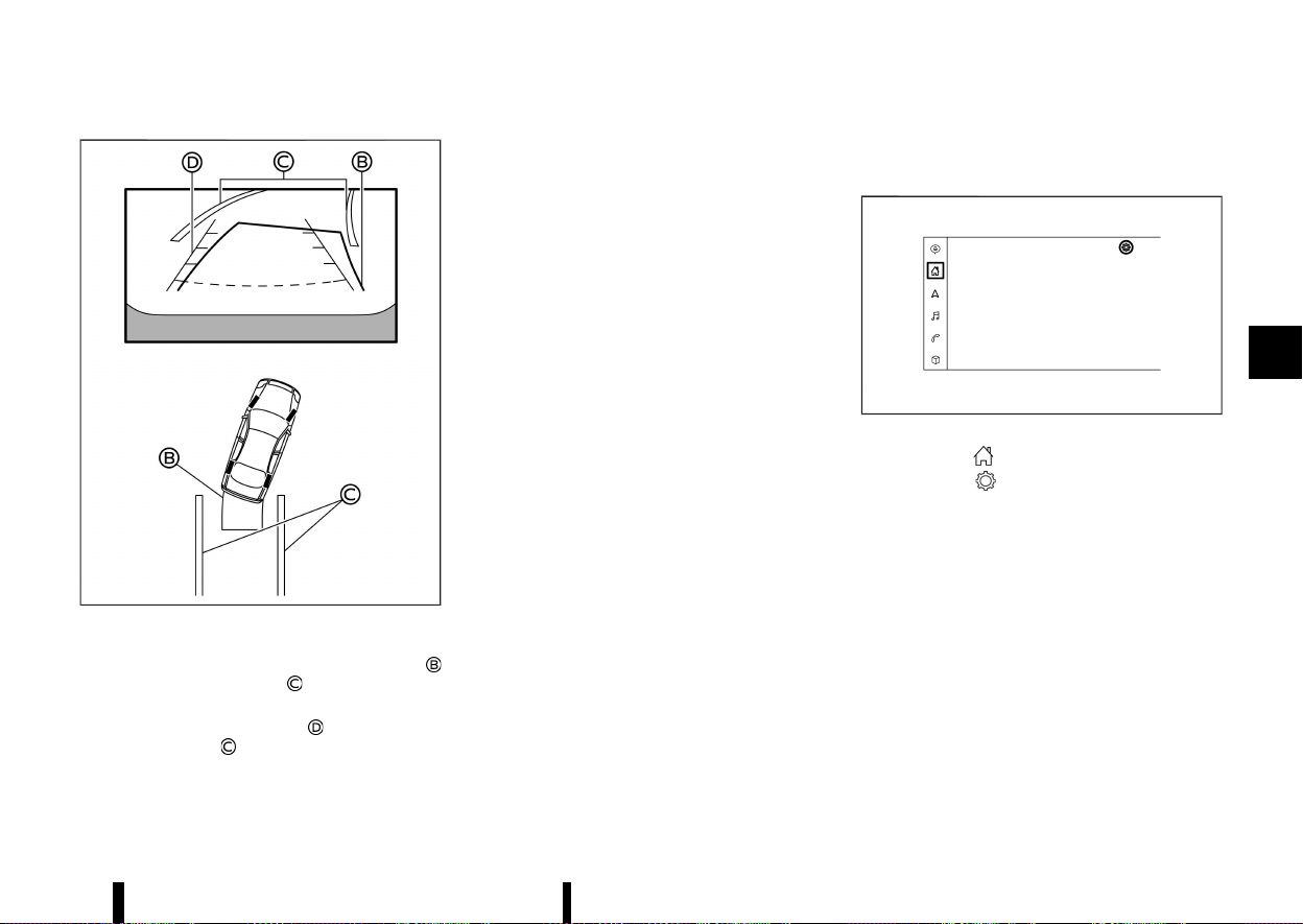
(201,1)
MWAE0681X
3. Slowly reverse the vehicle adjusting the steer-
ing wheel so that the predictive course lines
enter the parking space .
4. Manoeuvre the steering wheel to make the
vehicle width guide lines
parallel to the
parking space
while referring to the pre-
dictive course lines.
5. When the vehicle is parked in the space
completely, place the shift position in the "P"
(Park) position and apply the parking brake.
HOW TO SWITCH THE DISPLAY
MEVT33A1-2D567CEA-A96B-41B0-9F85-390BCA892902
With the ignition switch placed in the "ON" posi-
tion, push the <CAMERA> button or move the shift
lever to the "R" (Reverse) position to operate the
Intelligent Around View Monitor.
The Intelligent Around View Monitor displays
different split screen views depending on the
position of the shift lever. Push the <CAMERA>
button to switch between the available views.
If the shift lever is in the "R" (Reverse) position, the
available views are:
* Rear view/bird’s-eye view split screen
* Rear view/front-side view split screen
* Rear-wide view
If the shift lever is out of the "R" (Reverse) position,
the available views are:
* Front view/bird’s-eye view split screen
* Front view/front-side view split screen
* Front-wide view
The display will switch from the Intelligent Around
View Monitor screen when:
* The shift lever is in the "D" (Drive) position and
the vehicle speed increases above approxi-
mately 10 km/h (6 MPH).
* A different screen is selected.
ADJUSTING THE SCREEN
MEVT33A1-C45820B3-561B-48A2-8BF6-7333054DF40A
Type A:
MWAE0878X
1. Touch the “ ” key.
2. Touch the "
" key.
3. Touch the [Camera] key.
4. Touch the [Display Settings] key.
5. Touch the [+] or [-] key of the desired item on
the touch screen display. You can change the
brightness, contrast, tint, colour and black
level.
Monitor, heater, air conditioner, audio and phone systems 197
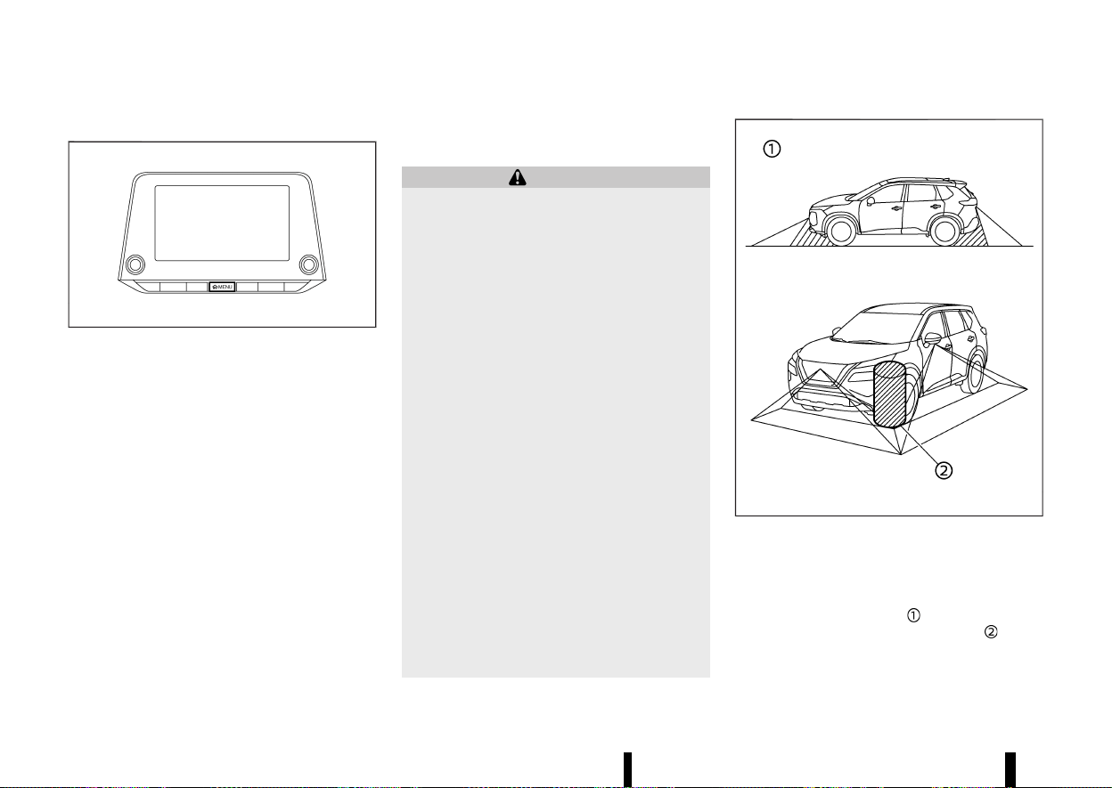
(202,1)
198 Monitor, heater, air conditioner, audio and phone systems
Type B:
MWAE0034X
1. Push the <MENU> button.
2. Touch the [Settings] key and then touch the
[Camera] key.
3. Touch the [Display Settings] key.
4. Touch the [Brightness], [Contrast], [Tint], [Col-
our], or [Black Level] key.
5. Adjust the item by touching the [+] or [–] key on
the touch screen display.
NOTE:
Do not adjust any of the Intelligent Around View
Monitor settings while the vehicle is moving.
Make sure the parking brake is firmly applied.
INTELLIGENT AROUND VIEW MONITOR
SYSTEM LIMITATIONS
MEVT33A1-EE79ACAF-7ADE-4229-B6D4-B6076A484785
WARNING
Listed below are the system limitations for
Intelligent Around View Monitor. Failure to
operate the vehicle in accordance with these
system limitations could result in serious injury
or death.
* Do not use the Intelligent Around View
Monitor with the outside rearview mirrors
in the stored position, and make sure that
the back door is securely closed when
operating the vehicle using the Intelligent
Around View Monitor.
* The apparent distance between objects
viewed on the Intelligent Around View
Monitor differs from the actual distance.
* The cameras are installed on the front
grille, the outside rearview mirrors and
above the rear number plate. Do not put
anything on the cameras.
* When washing the vehicle with high pres-
sure water, be sure not to spray it around
the cameras. Otherwise, water may enter
the camera unit causing water condensa-
tion on the lens, a malfunction, fire or an
electric shock.
* Do not strike the cameras. They are preci-
sion instruments. Doing so could cause a
malfunction or cause damage resulting in
a fire or an electric shock.
MWAE0345X
There are some areas where the system will not
show objects and the system does not warn of
moving objects. When in the front or the rear view
display, an object below the bumper or on the
ground may not be viewed
. When in the bird’s-
eye view, a tall object near the seam
of the
camera viewing areas will not appear in the
monitor.
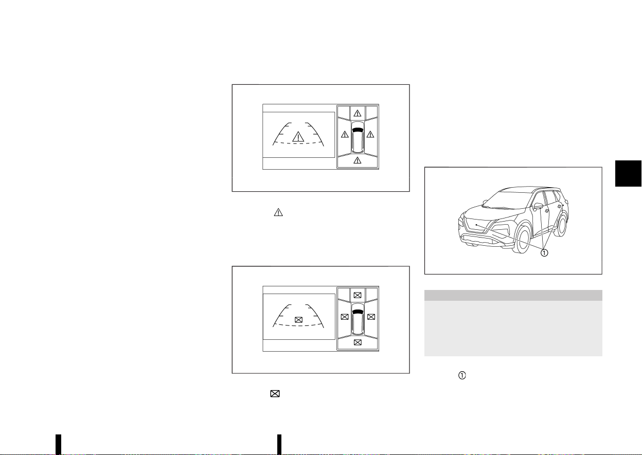
(203,1)
The following are operating limitations and do not
represent a system malfunction:
* There may be a delay when switching be-
tween views.
* When the temperature is extremely high or
low, the screen may not display objects clearly.
* When strong light directly shines on the
camera, objects may not be displayed clearly.
* The screen may flicker under fluorescent light.
* The colours of objects on the Intelligent
Around View Monitor may differ somewhat
from the actual colour of objects.
* Objects on the Intelligent Around View Monitor
may not be clear and the colour of the object
may differ in a dark environment.
* There may be differences in sharpness be-
tween each camera view of the bird’s-eye
view.
* Do not use wax on the camera lens. Wipe off
any wax with a clean cloth that has been
dampened with a diluted mild cleaning agent,
then wipe with a dry cloth.
System temporarily unavailable
MEVT33A1-C12157D5-4FE3-48BE-BF7F-1D7F042138EE
MWAE0473X
When the “ ” icon is displayed on the screen,
there will be abnormal conditions in the Intelligent
Around View Monitor. This will not hinder normal
driving operation but the system should be
inspected. It is recommended you visit a NISSAN
dealer or qualified workshop.
MWAE0474X
When the “ ” icon is displayed on the screen, the
camera image may be receiving temporary elec-
tronic disturbances from surrounding devices. This
will not hinder normal driving operation but the
system should be inspected. It is recommended
you visit a NISSAN dealer or qualified workshop.
The screen layout in the illustration is for the Left-
Hand Drive (LHD) model. For the Right-Hand Drive
(RHD) model, the screen layout will be opposite.
SYSTEM MAINTENANCE
MEVT33A1-2F1405BC-38E9-44B8-B2D2-800FC0E566C8
MWAE0360X
CAUTION
* Do not use alcohol, benzine or thinner to
clean the camera. This will cause disco-
loration.
* Do not damage the camera as the monitor
screen may be adversely affected.
If dirt, rain or snow accumulates on any of the
cameras
, the Intelligent Around View Monitor
may not display objects clearly. Clean the camera
by wiping with a cloth dampened with a diluted
Monitor, heater, air conditioner, audio and phone systems 199
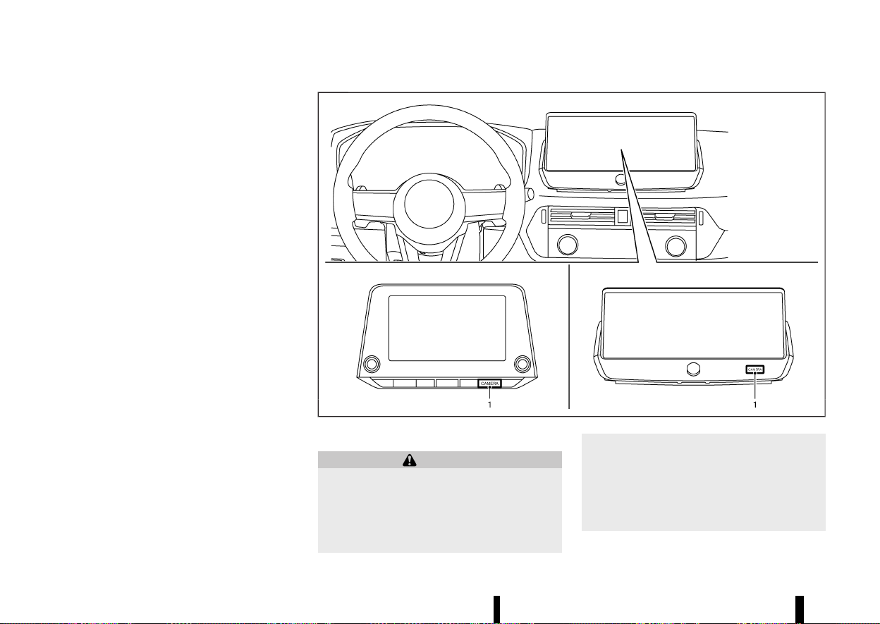
(204,1)
200 Monitor, heater, air conditioner, audio and phone systems
mild cleaning agent and then wiping with a dry
cloth.
MEVT33A1-9F3BEFA8-80BD-44D6-BA01-62BFBE01EEB2
MWAE0877X
1. <CAMERA> button
WARNING
* Failure to follow the warnings and instruc-
tions for proper use of the Moving Object
Detection system could result in serious
injury or death.
* The MOD system is not a substitute for
proper vehicle operation and is not de-
signed to prevent contact with objects
surrounding the vehicle. When manoeuvr-
ing, always use the outside rearview mirror
and rearview mirror and turn and check
the surroundings to ensure it is safe to
manoeuvre.
* The system is deactivated at speeds above
MOVING OBJECT DETECTION
(MOD) (where fitted)
MOVING OBJECT DETECTION (MOD) (where fitted)
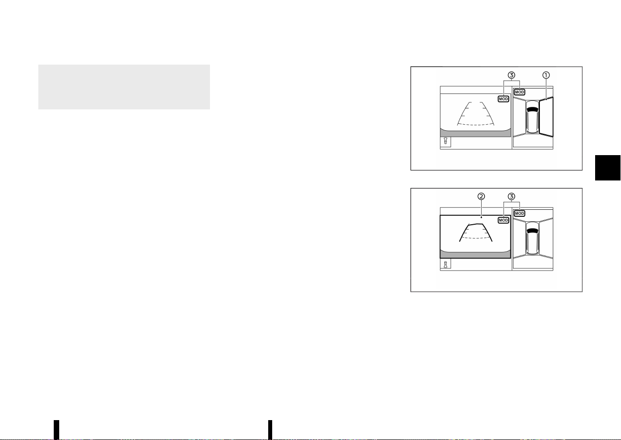
(205,1)
8 km/h (5 MPH). It is reactivated at lower
speeds.
* The MOD system is not designed to detect
the surrounding stationary objects.
The MOD system can inform the driver of moving
objects near the vehicle when driving out of
garages, manoeuvring in parking lots and in other
such instances.
The MOD system detects moving objects by using
image processing technology on the image shown
in the display.
MOD SYSTEM OPERATION
MEVT33A1-C973A40E-BB0D-4AE5-9A78-CA4400F7BAC8
The MOD system will turn on automatically under
the following conditions:
* When the shift lever is in the "R" (Reverse)
position.
* When the <CAMERA> button is pushed to
activate the Intelligent Around View Monitor
system on the display.
* When vehicle speed decreases below approxi-
mately 8 km/h (5 MPH).
The MOD system operates in the following condi-
tions when the camera view is displayed:
* When the shift lever is in the "P" (Park) or "N"
(Neutral) position and the vehicle is stopped,
the MOD system detects the moving objects in
the bird’s-eye view. The MOD system will not
operate if either door is opened. If outside
rearview mirrors are folded, MOD may not
operate properly.
* When the shift lever is in the "D" (Drive)
position, and the vehicle speed is below
approximately 8 km/h (5 MPH), the MOD
system detects moving objects in the front
view or front-wide view.
* When the shift lever is in the "R" (Reverse)
position and the vehicle speed is below
approximately 8 km/h (5 MPH), the MOD
system detects moving objects in the rear
view or rear-wide view. The MOD system will
not operate if the back door is open.
The MOD system does not detect moving objects
in the front-side view. The MOD icon is not
displayed on the screen when in this view.
When the MOD system detects a moving object
near the vehicle, the yellow frame will be displayed
on the view where the object is detected and a
chime will sound once. While the MOD system
continues to detect moving objects, the yellow
frame continues to be displayed.
NOTE:
While the RCTA chime (where fitted) is beeping,
the MOD system does not chime.
MWAE0548X
Front and bird’s-eye views
MWAE0683X
Rear and bird’s-eye views
Monitor, heater, air conditioner, audio and phone systems 201
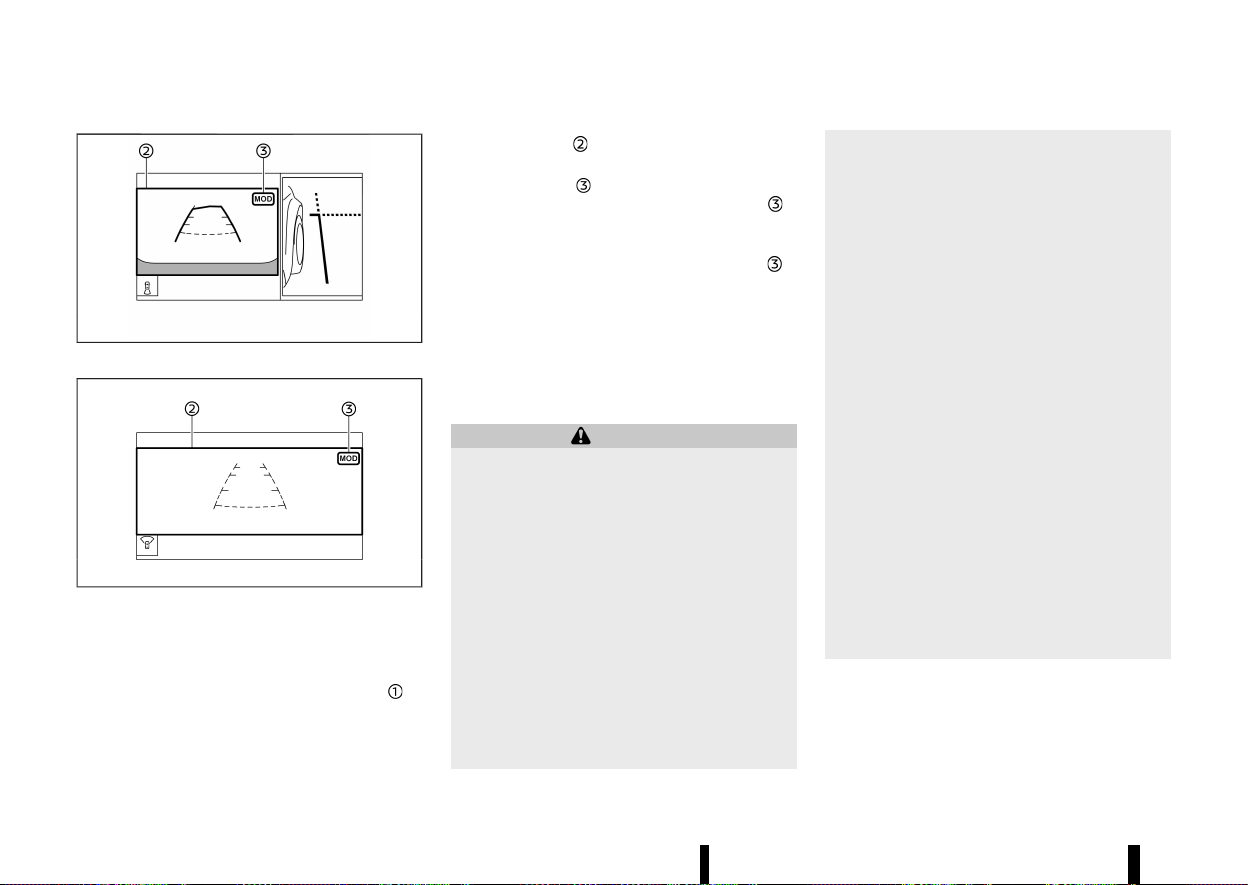
(206,1)
202 Monitor, heater, air conditioner, audio and phone systems
MWAE0684X
Rear and front-side views
MWAE0550X
Front-wide view / rear-wide view
The screen layout in the illustration is for the Left-
Hand Drive (LHD) model. For the Right-Hand Drive
(RHD) model, the screen layout will be opposite.
In the bird’s-eye view, the yellow frame
is
displayed on each camera image (front, rear, right,
left) depending on where moving objects are
detected.
The yellow frame
is displayed on the front view,
rear view, front-wide view and rear-wide view.
A green MOD icon
is displayed in the view where
the MOD system is operative. A grey MOD icon
is
displayed in the view where the MOD system is not
operative.
If the MOD system is turned off, the MOD icon
is
not displayed.
TURNING MOD ON AND OFF
MEVT33A1-C3E1369B-A619-4BCF-840A-8693E26EF043
The MOD system can be turned on and off using
the vehicle information display. (See “[Driver Assis-
tance]” (P.83).)
MOD SYSTEM LIMITATIONS
MEVT33A1-0AD4346F-D778-4F3B-A04D-B992B8290BC1
WARNING
Listed below are the system limitations for
MOD. Failure to operate the vehicle in accor-
dance with these system limitations could
result in serious injury or death.
* Do not use the MOD system when towing a
trailer. The system may not function prop-
erly.
* Excessive noise (for example, audio system
volume or open vehicle window) will inter-
fere with the chime sound, and it may not
be heard.
* The MOD system performance will be
limited according to environmental condi-
tions and surrounding objects such as:
— When there is low contrast between
background and the moving objects.
— When there is blinking source of light.
— When strong light such as another
vehicle’s headlight or sunlight is pre-
sent.
— When camera orientation is not in its
usual position, such as when the out-
side rearview mirror is folded.
— When there is dirt, water drops or
snow on the camera lens.
— When the position of the moving
objects in the display is not changed.
* The MOD system might detect flowing
water droplets on the camera lens, white
smoke from the muffler, moving shadows,
etc.
* The MOD system may not function prop-
erly depending on the speed, direction,
distance or shape of the moving objects.
* If your vehicle sustains damage to the
parts where the camera is installed, leav-
ing it misaligned or bent, the sensing zone
may be altered and the MOD system may
not detect objects properly.
* When the temperature is extremely high or
low, the screen may not display objects
clearly. This is not a malfunction.
NOTE:
The green MOD icon will change to orange if one
of the following has occurred.
* When the system is malfunctioning.

(207,1)
* When the component temperature reaches
a high level.
* When the rear view camera has detected a
blockage.
If the icon light continues to illuminate in
orange, have the MOD system checked. It is
recommended that you visit a NISSAN dealer or
qualified workshop for this service.
SYSTEM MAINTENANCE
MEVT33A1-6E3883AB-CE07-4F38-B1AA-CD2519C9F3D8
MWAE0360X
CAUTION
* Do not use alcohol, benzine or thinner to
clean the camera. This will cause disco-
loration.
* Do not damage the camera as the monitor
screen may be adversely affected.
If dirt, rain or snow accumulates on any of the
cameras
, the MOD system may not operate
properly. Clean the camera by wiping with a cloth
dampened with a diluted mild cleaning agent and
then wiping with a dry cloth.
MEVT33A1-61D1CD55-228C-4E52-9461-782B71C38C8B
CENTRE VENTS
MEVT33A1-64E14B11-BF5F-4D35-97C4-552604CBA3E1
MWAE0346X
Open/close the vents by moving the control to
either direction.
Adjust the air flow direction of the vents by moving
the centre knob (up/down, left/right) until the
desired position is achieved.
SIDE VENTS
MEVT33A1-032F27BA-821C-405D-8DDF-C8E8265CDAB1
MWAE0347X
Right side
Monitor, heater, air conditioner, audio and phone systems 203
VENTS
VENTS
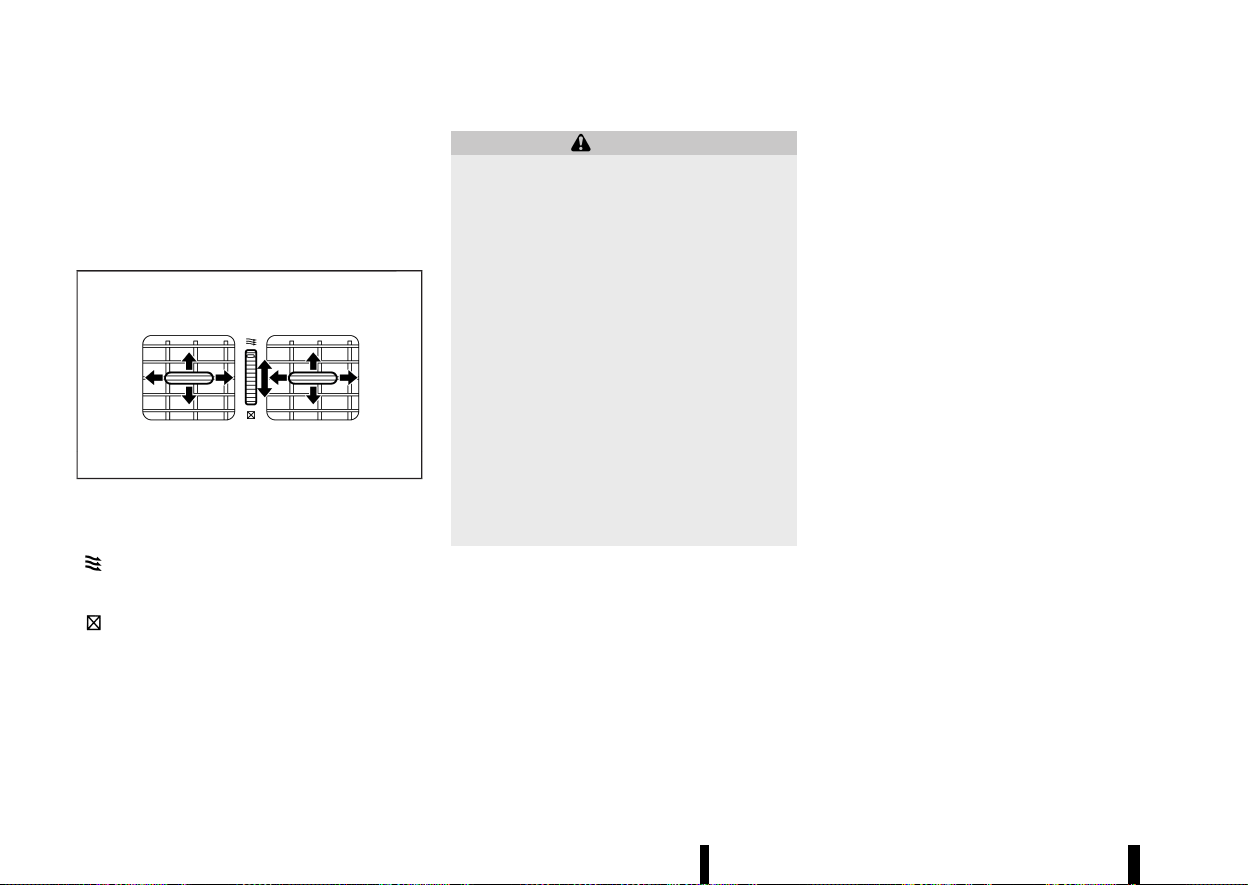
(208,1)
204 Monitor, heater, air conditioner, audio and phone systems
Open/close the vents by moving the control to
either direction.
Adjust the air flow direction of the vents by moving
the centre knob (up/down, left/right) until the
desired position is achieved.
REAR VENTS
MEVT33A1-BCE7AE15-E08B-4616-BA5C-286030C15215
MJVH0940X
Open/close the vents by moving the control to
either direction.
: This symbol indicates that the vents are
open. Moving the side control to this direc-
tion will open the vents.
: This symbol indicates that the vents are
closed. Moving the side control to this
direction will close the vents.
Adjust the air flow direction of the vents by moving
the centre knob (up/down, left/right) until the
desired position is achieved.
MEVT33A1-F6744F12-5D11-4E4D-82E1-CE3DF32B9B61
WARNING
* The heater and air conditioner operate
only when the engine is running.
* Never leave children or adults who would
normally require the support of others
alone in the vehicle. Pets should not be
left alone either. They could unknowingly
activate switches or controls and inadver-
tently become involved in a serious acci-
dent and injure themselves. On hot, sunny
days, temperatures in a closed vehicle
could quickly become high enough to
cause severe or possibly fatal injuries to
people or animals.
* Do not use the recirculation mode for long
periods as it may cause the interior air to
become stale and the windows to fog up.
* Do not adjust the heating and air condi-
tioning controls while driving so that full
attention may be given to vehicle opera-
tion.
The heater and air conditioner operate when the
engine is running. The air blower will operate even
if the engine is turned off and the ignition switch is
placed in the "ON" position.
NOTE:
* Odours from inside and outside the vehicle
can build up in the air conditioner unit.
Odour can enter the passenger compart-
ment through the vents.
* When parking, set the heater and air condi-
tioner controls to turn off air recirculation to
allow fresh air into the passenger compart-
ment. This should help reduce odours inside
the vehicle.
While the engine is stopped by the Stop/Start
System, activating the front defogger will cause
the engine to automatically restart.
While the engine is running, activating the front
defogger will prevent the Stop/Start System from
automatically stopping the engine.
When the engine is stopped by the Stop/Start
System, heater and air conditioner performance
may be reduced. To keep full heater and air
conditioner performance, restart the engine by
pushing the Stop/Start OFF switch. (See “Stop/
Start System” (P.255).)
OPERATING TIPS (for automatic air
conditioner)
MEVT33A1-0CAD1583-372A-44FE-BAC7-174E3DF52F96
When the engine coolant temperature and outside
air temperature are low, the air flow from the foot
outlets may be limited when in the automatic
mode. However, this is not a malfunction. After the
coolant temperature warms up, air flow from the
foot outlets will operate normally.
For rear temperature control (where fitted):
* The purpose of the rear temperature control is
to vary the temperature of the rear air flow.
* The amount of air flow to the rear vents is
primarily controlled by the front passenger’s
blower and mode settings.
* The amount of air flow to the rear vents is also
affected by the rear temperature setting.
Higher rear temperature settings have lower
HEATER AND AIR CONDITIONER
HEATER AND AIR CONDITIONER
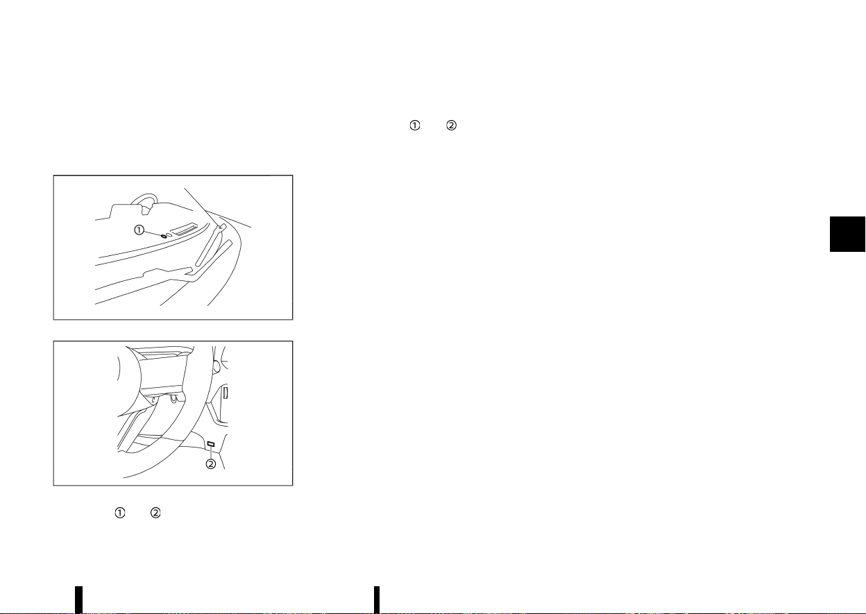
(209,1)
air flow amounts than cooler temperature
settings. This condition ensures better com-
fort to the head and face area, while primary
heating for the rear passenger seats is pro-
vided through the foot outlets.
Sensors:
MWAE0350X
MWAE0351X
The sensors and , located on the instrument
panel, help maintain a constant temperature. Do
not put anything on or around the sensors.
The layout in the illustration is for the Left-Hand
Drive (LHD) model. For the Right-Hand Drive (RHD)
model, the sensors
and are located on the
opposite side.
Monitor, heater, air conditioner, audio and phone systems 205
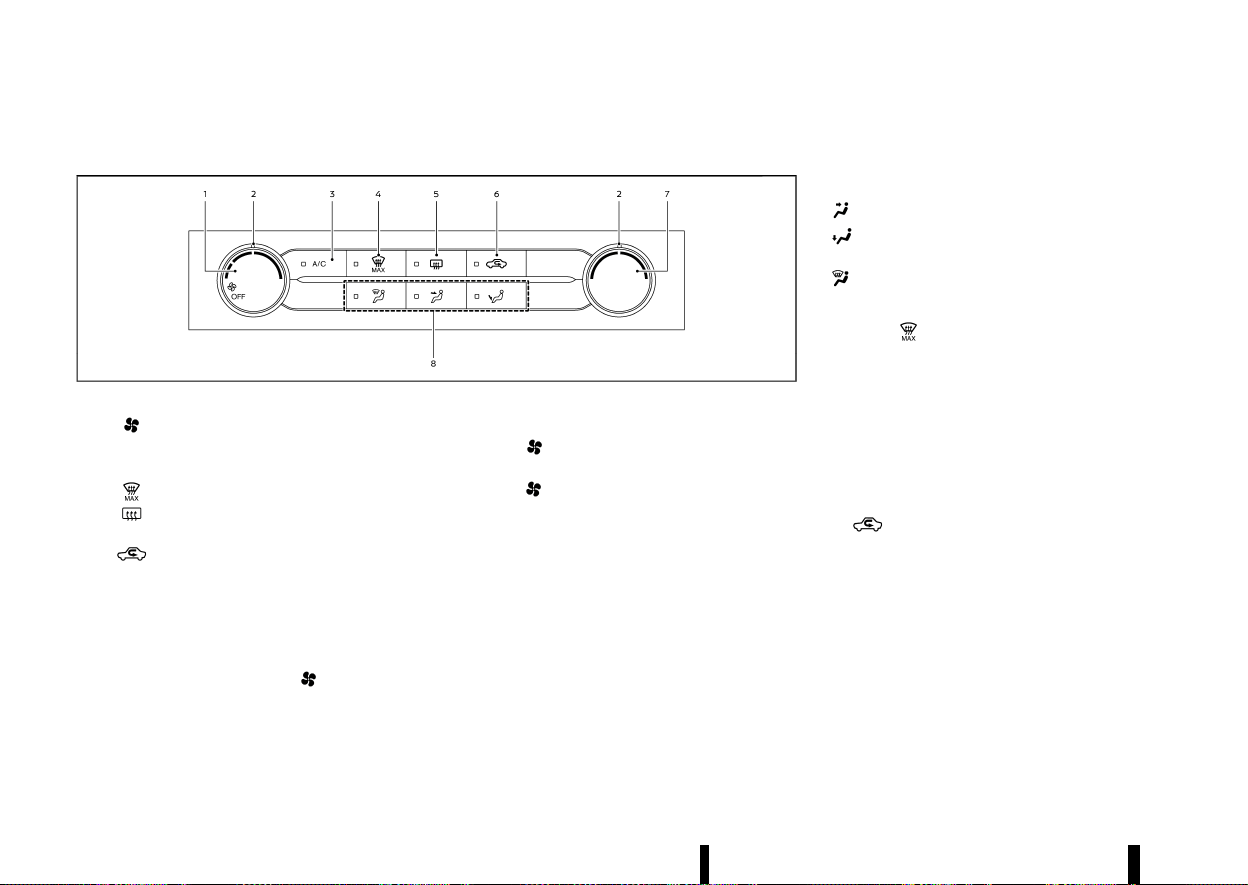
(210,1)
206 Monitor, heater, air conditioner, audio and phone systems
MANUAL AIR CONDITIONER AND HEATER
MEVT33A1-42035F3C-2FA7-4604-B8A7-E9D090BA78F0
MWAE0879X
Left-Hand Drive (LHD) models
1. (fan speed control) dial
2. Dial pointers
3. <A/C> (air conditioner) button
4.
(front defogger MAX) button
5.
(rear window defogger) button (See
“Defogger switch” (P.119).)
6.
(air recirculation) button
7. Temperature control dial
8. Air flow control buttons
Controls
MEVT33A1-CF0516C2-F8B2-4B6C-A329-1C093243CB8D
Turning system on/off:
To turn on the system, turn the
dial out of the
OFF position. Turn the dial anticlockwise to the
OFF position to turn off the system.
Fan speed control:
Turn the
dial clockwise to increase the fan
speed.
Turn the
dial anticlockwise to decrease the
fan speed.
The dial pointer indicates the fan speed level.
Temperature control:
Turn the temperature control dial to set the
desired temperature. Turn the dial between the
middle and the right position to select the hot
temperature. Turn the dial between the middle
and the left position to select the cool tempera-
ture. The dial pointer indicates the temperature
level.
Air flow control:
Push one of the air flow control buttons to select
the air flow outlets.
— Air flows mainly from centre and side vents.
— Air flows mainly from the foot outlet and
partly from the defogger.
— Air flows mainly from the defogger.
MAX defogging/defrosting:
Push the
button to turn on the MAX defog-
ging/defrosting mode and quickly defog/defrost
the windscreen. When this mode is turned on, the
A/C indicator light will turn on and the air
circulation will be fixed at the outside air circula-
tion mode. For the best performance, turn the
temperature control dial to the maximum hot
position and set the fan speed at its maximum.
Air intake control:
The air intake control mode will change each time
the
button is pushed.
* When the indicator light is turned on, the air
recirculates inside the vehicle.
* When the indicator light is turned off, the air
flow is drawn from outside the vehicle.
A/C (Air Conditioner) OPERATION:
Push the <A/C> button to turn on or off the air
conditioner. When the air conditioner is on, the A/C
indicator light on the button illuminates.
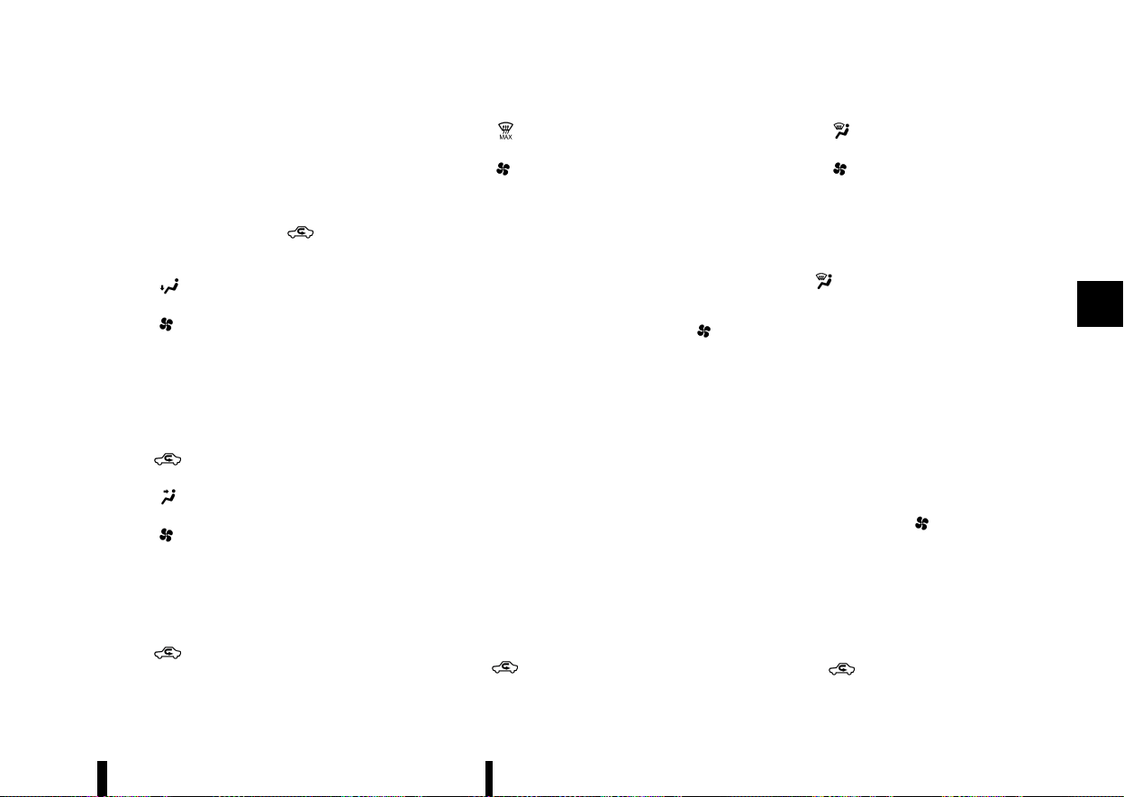
(211,1)
Heater operation
MEVT33A1-B0B550D2-480B-46C9-9AB9-84830EBC22E6
Heating:
This mode is used to direct heated air from the
foot outlets. Some air also flows from the defogger
outlets and the side vent outlets.
1. For normal heating, push the
button to
turn the indicator light off for selecting the
outside air circulation.
2. Push the
button. (The indicator light will
turn on.)
3. Turn the
dial to the desired position.
4. Turn the temperature control dial to the
desired position between the middle and the
hot (right) position.
Ventilation:
This mode directs outside air from the side and
centre vents.
1. Push the
button to turn the indicator off
for selecting the outside air recirculation.
2. Push the
button. (The indicator light will
turn on.)
3. Turn the
dial to the desired position.
4. Turn the temperature control dial to the
desired position.
Defrosting or defogging:
This mode directs the air to the defogger outlets to
defrost/defog the windows.
1. Push the
button to turn the indicator off
for selecting the outside air recirculation.
2. Push the
button. (The indicator light will
turn on.)
3. Turn the
dial to the desired position.
4. Turn the temperature control dial to the
desired position between the middle and the
hot (right) position.
5. Turn the side vents to the side windows to
defrost or defog for a clear view to the side
mirrors.
To remove frost from the windscreen quickly,
turn the temperature control dial to the
maximum hot (right) position and the
dial to the maximum position.
If it is difficult to defog the windscreen, push
the <A/C> button. (The indicator light will turn
on.)
When the front defogger mode is selected, the
air conditioner automatically turns on if the
outside temperature is more than slightly
above freezing. This dehumidifies the air which
helps defog the windscreen. The air recircula-
tion indicator light automatically turns off,
allowing outside air to be drawn into the
passenger compartment to further improve
the defogging performance. The recirculation
mode cannot be activated in the front defog-
ger mode.
Heating and defogging:
This mode heats the interior and defogs the
windows.
1. Push the
button to turn the indicator off
for selecting the outside air recirculation.
2. Push the
button. (The indicator light will
turn on.)
3. Turn the
dial to the desired position.
4. Turn the temperature control dial to the
maximum hot (right) position.
5. Turn the side vents to the side windows to
defrost or defog for a clear view to the side
mirrors.
When the
button is pushed, the air condi-
tioner automatically turns on if the outside tem-
perature is more than slightly above freezing. This
dehumidifies the air which helps defog the wind-
screen. The air recirculation indicator light auto-
matically turns off, allowing outside air to be drawn
into the passenger compartment to further im-
prove the defogging performance.
NOTE:
Clear snow and ice from the wiper blades and air
inlet in front of the windscreen. This improves
heater operation.
Air conditioner operation
MEVT33A1-B032F425-F65B-45E6-A592-97C63A9CA4F0
Start the engine, turn the dial to the desired
position, and push the <A/C> button to activate
the air conditioner. When the air conditioner is on,
cooling and dehumidifying functions are added to
the heater operation. The air conditioner cooling
function operates only when the engine is running.
Cooling:
This mode is used to cool and dehumidify the air.
1. Push the
button to turn the indicator off
for selecting the outside air recirculation.
Monitor, heater, air conditioner, audio and phone systems 207

(212,1)
208 Monitor, heater, air conditioner, audio and phone systems
2. Push the button. (The indicator light will
turn on.)
3. Turn the
dial to the desired position.
4. Push the <A/C> button. (The indicator light will
turn on.)
5. Turn the temperature control dial to the
desired position between the middle and the
cool (left) position.
Dehumidified heating:
This mode is used to heat and dehumidify the air.
1. Push the
button to turn the indicator off
for selecting the outside air recirculation.
2. Push the
button. (The indicator light will
turn on.)
3. Turn the
dial to the desired position.
4. Push the <A/C> button on. (The indicator light
will turn on.)
5. Turn the temperature control dial to the
desired position between the middle and the
hot (right) position.
Dehumidified defogging:
This mode is used to defog the windows and
dehumidify the air.
1. Push the
button to turn the indicator off
for selecting the outside air recirculation.
2. Push the
button. (The indicator light will
turn on.)
3. Turn the
dial to the desired position.
4. Push the <A/C> button. (The indicator light will
turn on.)
5. Turn the temperature control dial to the
desired position.
When the
mode is selected, the air condi-
tioner automatically turns on if the outside tem-
perature is more than slightly above freezing. This
dehumidifies the air which helps defog the wind-
screen. The air recirculation mode automatically
turns off, allowing outside air to be drawn into the
passenger compartment to further improve the
defogging performance.
NOTE:
* The air conditioner system should be oper-
ated for approximately 10 minutes at least
once a month. This helps prevent damage to
the air conditioner system due to the lack of
lubrication.
* A visible mist may be seen coming from the
vents in hot, humid conditions as the air is
cooled rapidly. This does not indicate a
malfunction.
* If the engine coolant temperature becomes
too high, the air recirculation mode will be
activated and the indicator light will turn on
automatically.
* If the engine coolant temperature gauge
indicates engine coolant temperature over
the normal range, turn the air conditioner
off. (See “If your vehicle overheats” (P.411).)
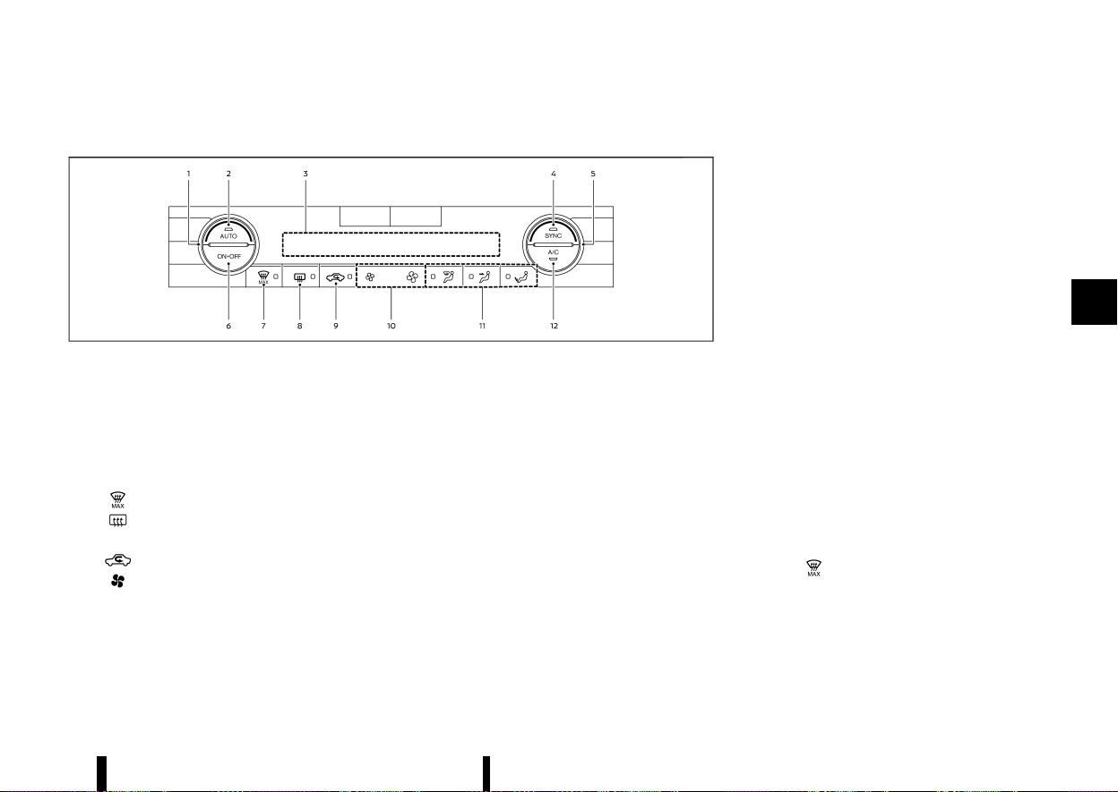
(213,1)
AUTOMATIC AIR CONDITIONER (models without rear control)
MEVT33A1-4575D365-E8AE-43CA-854C-1155F41013BA
MWAE0880X
Example (Left-Hand Drive (LHD) models)
1. Temperature control dial (driver’s side)
2. <AUTO> (automatic) button
3. Display screen
4. <SYNC> (synchronize) button
5. Temperature control dial (passenger’s side)
6. <ON·OFF> button
7.
(front defogger MAX) button
8.
(rear window defogger) button
(See “Defogger switch” (P.119).)
9.
(air recirculation) button
10.
(fan speed control) buttons
11. Air flow control buttons
12. <A/C> (air conditioner) button
The layout of the buttons may vary depending on
the models and specifications.
Automatic operation
MEVT33A1-2CF2387D-E185-41A8-9EAE-A4C940EF755A
Cooling and/or dehumidified heating (AUTO):
This mode may be used all year round as the
system automatically works to keep a constant
temperature. Air flow distribution and fan speed
are also controlled automatically.
1. Push the <AUTO> button on. (The indicator
light on the button will illuminate.)
2. Turn the temperature control dial on the
corresponding side to set the desired tem-
perature.
.
You can individually set temperatures for
the driver’s side and front passenger’s side
when the indicator light on the <SYNC>
button is not illuminated.
A visible mist may be seen coming from the vents
in hot, humid conditions as the air is cooled rapidly.
This does not indicate a malfunction.
Heating (A/C OFF):
The air conditioner does not activate in this mode.
Use this mode when you only need to heat.
1. Push the <AUTO> button on. (The indicator
light on the button will illuminate.)
2. Push the <A/C> button. (The indicator light will
turn off.)
3. Turn the temperature control dial on the
corresponding side to set the desired tem-
perature.
.
You can individually set temperatures for
the driver’s side and front passenger’s side
when the indicator light on the <SYNC>
button is not illuminated.
.
The temperature of the passenger com-
partment will be maintained automatically.
Air flow distribution and fan speed are also
controlled automatically.
NOTE:
* Do not set the temperature lower than the
outside air temperature or the system may
not work properly.
* Not recommended if windows fog up.
MAX defrosting/defogging:
Push the
button to turn on the MAX defog-
ging/defrosting mode and quickly defog/defrost
the windscreen. When this mode is turned on, the
fan will be at its maximum speed, the A/C indicator
light will turn on, and the air circulation will be fixed
at the outside air circulation mode.
Do not set the temperature too low when the front
defogger mode is on (the indicator light on the
Monitor, heater, air conditioner, audio and phone systems 209

(214,1)
210 Monitor, heater, air conditioner, audio and phone systems
button is illuminated), because doing so may
fog up the windscreen.
Manual operation
MEVT33A1-D56D6887-2B73-4DD1-A2AC-7ADADE6922DE
Fan speed control:
Push the
buttons to manually control the fan
speed.
Air intake control:
The air intake control mode will change each time
the
button is pushed.
* When the indicator light is turned on, the air
recirculates inside the vehicle.
* When the indicator light is turned off, the air
flow is drawn from outside the vehicle.
* To switch to automatic control mode, push
and hold the
button for about 2 seconds.
The indicator light will blink, and then the air
intake will be controlled automatically.
Air flow control:
Push one of the air flow control buttons to select
the air flow outlets.
— Air flows mainly from centre and side vents.
— Air flows mainly from the foot outlet and
partly from the defogger.
— Air flows mainly from the defogger.
Synchronize temperature settings:
Push the <SYNC> button to turn on the SYNC
mode. (The indicator light on the button will turn
on.)
When the SYNC mode is active, the driver’s side
temperature control dial will control the driver’s
and front passenger’s side temperatures.
To exit the SYNC mode, change the passenger’s
side temperature using the temperature control
dial on the front passenger’s side. (The indicator
light on the <SYNC> button will turn off.)
To turn the system off
MEVT33A1-23ABCF2A-3E43-4A69-800A-1941EB292CAE
Push the <ON·OFF> button.
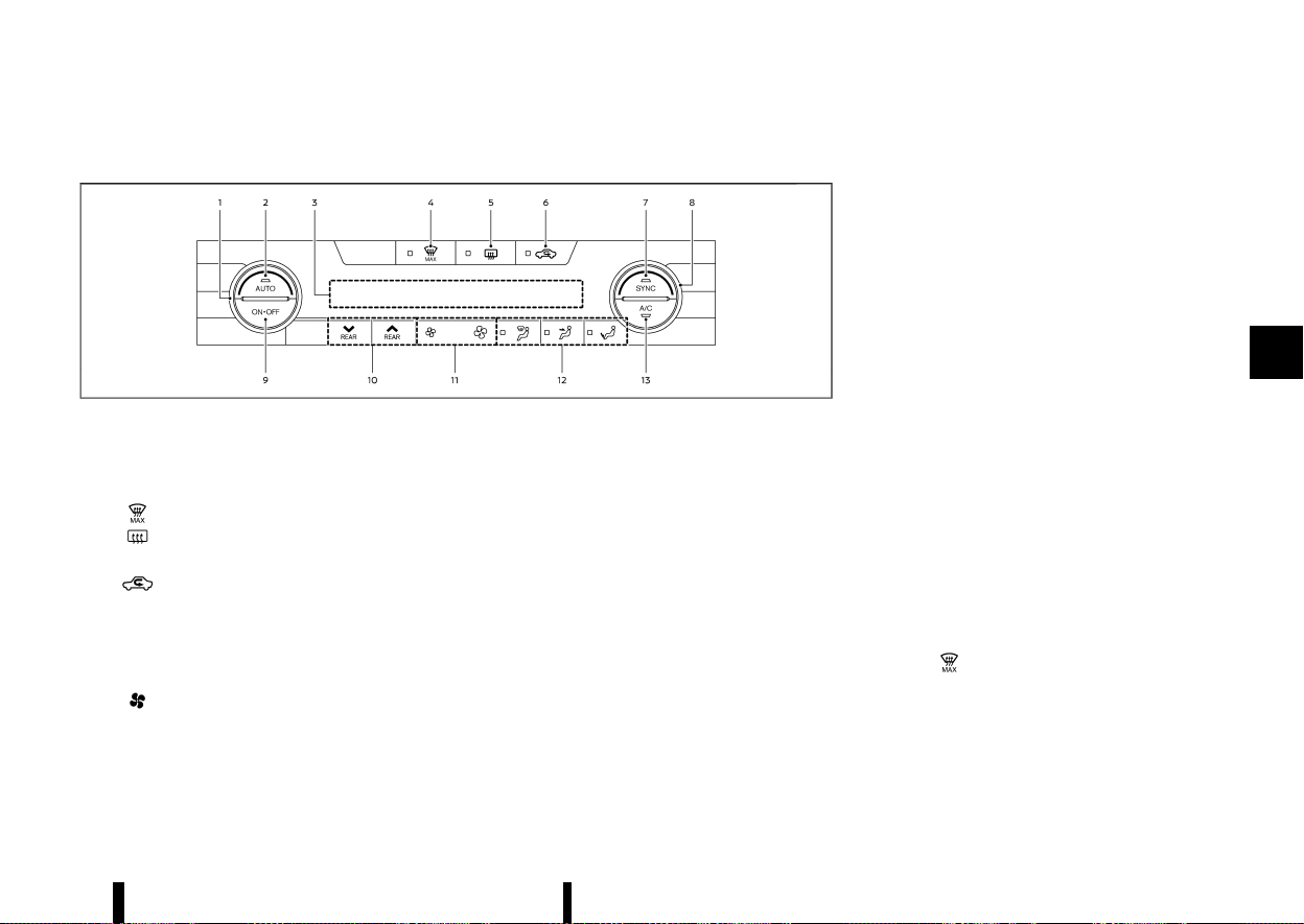
(215,1)
AUTOMATIC AIR CONDITIONER (models with rear control)
MEVT33A1-83951EF3-A62A-454E-99D8-41679FA07040
MWAE0881X
Example (Left-Hand Drive (LHD) models)
1. Temperature control dial (driver’s side)
2. <AUTO> (automatic) button
3. Display screen
4.
(front defogger MAX) button
5.
(rear window defogger) button
(See “Defogger switch” (P.119).)
6.
(air recirculation) button
7. <SYNC> (synchronize) button
8. Temperature control dial (passenger’s side)
9. <ON·OFF> button
10. Rear temperature control buttons
11.
(fan speed control) buttons
12. Air flow control buttons
13. <A/C> (air conditioner) button
The layout of the buttons may vary depending on
the models and specifications.
Automatic operation
MEVT33A1-7761981F-B0A3-4954-9903-B0ABCE9BC1AD
Cooling and/or dehumidified heating (AUTO):
This mode may be used all year round as the
system automatically works to keep a constant
temperature. Air flow distribution and fan speed
are also controlled automatically.
1. Push the <AUTO> button on. (The indicator
light on the button will illuminate.)
2. Turn the temperature control dial on the
corresponding side to set the desired tem-
perature.
.
You can individually set temperatures for
the driver’s side and front passenger’s side
when the indicator light on the <SYNC>
button is not illuminated.
A visible mist may be seen coming from the vents
in hot, humid conditions as the air is cooled rapidly.
This does not indicate a malfunction.
Heating (A/C OFF):
The air conditioner does not activate in this mode.
Use this mode when you only need to heat.
1. Push the <AUTO> button on. (The indicator
light on the button will illuminate.)
2. Push the <A/C> button. (The indicator light will
turn off.)
3. Turn the temperature control dial on the
corresponding side to set the desired tem-
perature.
.
You can individually set temperatures for
the driver’s side and front passenger’s side
when the indicator light on the <SYNC>
button is not illuminated.
.
The temperature of the passenger com-
partment will be maintained automatically.
Air flow distribution and fan speed are also
controlled automatically.
NOTE:
* Do not set the temperature lower than the
outside air temperature or the system may
not work properly.
* Not recommended if windows fog up.
MAX defrosting/defogging:
Push the
button to turn on the MAX defog-
ging/defrosting mode and quickly defog/defrost
the windscreen. When this mode is turned on, the
fan will be at its maximum speed, the A/C indicator
light will turn on, and the air circulation will be fixed
at the outside air circulation mode.
Do not set the temperature too low when the front
defogger mode is on (the indicator light on the
Monitor, heater, air conditioner, audio and phone systems 211
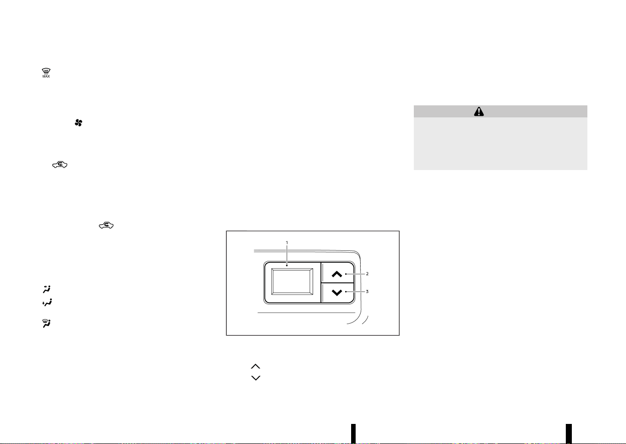
(216,1)
212 Monitor, heater, air conditioner, audio and phone systems
button is illuminated), because doing so may
fog up the windscreen.
Manual operation
MEVT33A1-80806BBA-5866-406A-A460-14FE05D20627
Fan speed control:
Push the
buttons to manually control the fan
speed.
Air intake control:
The air intake control mode will change each time
the
button is pushed.
* When the indicator light is turned on, the air
recirculates inside the vehicle.
* When the indicator light is turned off, the air
flow is drawn from outside the vehicle.
* To switch to automatic control mode, push
and hold the
button for about 2 seconds.
The indicator light will blink, and then the air
intake will be controlled automatically.
Air flow control:
Push one of the air flow control buttons to select
the air flow outlets.
— Air flows mainly from centre and side vents.
— Air flows mainly from the foot outlet and
partly from the defogger.
— Air flows mainly from the defogger.
Synchronize temperature settings:
Push the <SYNC> button to turn on the SYNC
mode. (The indicator light on the button will turn
on.)
When the SYNC mode is active, the driver’s side
temperature control dial will control the driver’s
side, front passenger’s side and rear temperatures.
When the passenger’s side temperature control
dial or the rear temperature control buttons are
operated, it will cancel the SYNC mode of the
individual zone. (The indicator light on the <SYNC>
button will remain on.)
Operating both the passenger’s side temperature
control dial and the rear temperature control
buttons will turn off the SYNC mode. (The indicator
light on the <SYNC> button will turn off.) (See “Rear
temperature control” (P.212).)
To turn the system off
MEVT33A1-591D2F7D-3999-4539-90B0-E2215229740F
Push the <ON·OFF> button.
Rear temperature control
MEVT33A1-05DC89E6-175A-417A-AE62-8933F4100F78
MJVH1847X
1. Rear temperature display
2. “
” Rear temperature increase button
3. “
” Rear temperature decrease button
You can adjust the temperature for rear seat
passengers using the buttons located on the back
side of the console box.
SERVICING AIR CONDITIONER
MEVT33A1-B5C6FE62-1A42-48C1-9AE1-B0167BBB8E1A
WARNING
The air conditioner system contains refriger-
ant under high pressure. To avoid personal
injury, any air conditioner service should be
done only by an experienced technician with
the proper equipment.
The air conditioner system in your vehicle is
charged with a refrigerant designed with the
environment in mind.
This refrigerant will not harm the earth’s ozone
layer. However, it may contribute in a small part to
global warming.
Special charging equipment and lubricant are
required when servicing your vehicle’s air condi-
tioner. Using improper refrigerants or lubricants
will cause severe damage to the air conditioner
system. (See “Air conditioner system refrigerant
and lubricant” (P.458).)
A NISSAN dealer or qualified workshop will be able
to service your environmentally friendly air condi-
tioner system.
Air conditioner filter
MEVT33A1-62F13102-7B44-4B25-9B28-B5CD74804A00
The air conditioner system is equipped with an air
conditioner filter. To make sure the air conditioner
heats, defogs, and ventilates efficiently, replace the
filter according to the specified maintenance
intervals listed in a separate maintenance booklet.
(217,1)
It is recommended to visit a NISSAN dealer or
qualified workshop to replace the filter.
The filter should be replaced if the air flow
decreases significantly or if windows fog up easily
when operating the heater or air conditioner.
MEVT33A1-CA50EA57-57F9-4E6D-B5A6-48F11C32DAC1
Models with NissanConnect System:
Refer to the separate NissanConnect Owner’s
Manual.
AUDIO OPERATION PRECAUTIONS
MEVT33A1-89F5A611-C620-4F3F-AB92-9617E7CA6A08
WARNING
Do not adjust the audio system while driving
so that full attention may be given to vehicle
operation.
The audio system operates when the ignition
switch is placed in the "ON" position. Do not use
for an extended period of time with the engine
stopped.
Radio
MEVT33A1-98C333D1-4C24-47A1-88D8-258779DD1AD3
* Radio reception is affected by station signal
strength, distance from radio transmitter,
buildings, bridges, mountains and other ex-
ternal influences. Intermittent changes in re-
ception quality normally are caused by these
external influences.
* Using a mobile phone in or near the vehicle
may influence radio reception quality.
* Some mobile phones or other devices may
cause interference or a buzzing noise to come
from the audio system speakers. Storing the
device in a different location may reduce or
eliminate the noise.
* Use the antenna for the best reception.
USB (Universal Serial Bus) CONNECTION PORT
MEVT33A1-D811F043-DEB5-444A-B4D0-2DBEBAF003F6
WARNING
Do not connect, disconnect or operate the USB
device while driving. Doing so can be a dis-
traction. If distracted you could lose control of
your vehicle and cause an accident or serious
injury.
CAUTION
* Do not force the USB device into the USB
connection port. Inserting the USB device
tilted or up-side-down into the USB con-
nection port may damage the USB con-
nection port. Make sure that the USB
device is connected correctly into the USB
connection port. (Some USB devices come
with a
mark as a guide. Make sure that
the mark is facing the correct direction
before inserting the device.)
* Do not grab the USB connection port cover
(where fitted) when pulling the USB device
out of the USB connection port. This could
damage the USB connection port and the
cover.
* Do not leave the USB cable in a place
where it can be pulled unintentionally.
Pulling the cable may damage the USB
connection port.
The vehicle is not equipped with a USB device. USB
devices should be purchased separately as neces-
sary.
Monitor, heater, air conditioner, audio and phone systems 213
AUDIO SYSTEM (where fitted)
AUDIO SYSTEM (where fitted)

(218,1)
214 Monitor, heater, air conditioner, audio and phone systems
This system cannot be used to format USB devices.
To format a USB device, use a personal computer.
In some states/area, the USB device for the front
seats plays only sound without images for reg-
ulatory reasons, even when the vehicle is parked.
This system supports various USB memory de-
vices, USB hard drives and iPod players. Some USB
devices may not be supported by this system.
* Partitioned USB devices may not be played
correctly.
* Some characters used in other languages
(Arabic, Japanese, etc.) are not displayed
properly on display. Using English language
characters with a USB device is recommended.
General notes for USB use:
Refer to your device manufacturer’s owner infor-
mation regarding the proper use and care of the
device.
Notes for iPod use:
“Made for iPod”, “Made for iPhone”, and “Made for
iPad” mean that an electronic accessory has been
designed to connect specifically to iPod, iPhone, or
iPad, respectively, and has been certified by the
developer to meet Apple performance standards.
Apple is not responsible for the operation of this
device or its compliance with safety and regulatory
standards.
Please note that the use of this accessory with
iPod, iPhone, or iPad may affect wireless perfor-
mance.
iPad, iPhone, iPod, iPod classic, iPod nano, iPod
shuffle, and iPod touch are trademarks of Apple
Inc., registered in the U.S. and other countries.
Lightning is a trademark of Apple Inc.
* NISSAN audio system supports only acces-
sories that Apple has certified and that come
with the “Made for iPod/iPhone/iPad” logo.
* Improperly plugging in the iPod may cause a
checkmark to be displayed on and off (flicker-
ing). Always make sure that the iPod is
connected properly.
* An iPod nano (1st Generation) may remain in
fast forward or rewind mode if it is connected
during a seek operation. In this case, please
manually reset the iPod.
* An iPod nano (2nd Generation) will continue to
fast-forward or rewind if it is disconnected
during a seek operation.
* An incorrect song title may appear when the
play mode is changed while using an iPod
nano (2nd Generation).
* Audiobooks may not play in the same order as
they appear on an iPod.
Bluetooth® AUDIO PLAYER
MEVT33A1-B208CDB8-250B-47F5-B6F9-ADCD583D86E7
* Wireless LAN (Wi-Fi) and the Bluetooth® func-
tions share the same frequency band (2.4 GHz).
Using the Bluetooth® and the wireless LAN
functions at the same time may slow down or
disconnect communication and cause unde-
sired noise. It is recommended that you turn
off the wireless LAN (Wi-Fi) when using the
Bluetooth® functions.
* Some Bluetooth® audio devices may not be
used with this system. For detailed informa-
tion about Bluetooth® audio devices that are
available for use with this system, contact a
NISSAN dealer or qualified workshop.
* Before using a Bluetooth® audio system, the
initial registration process for the audio device
is necessary.
* Operation of the Bluetooth® audio system
may vary depending on the audio device that
is connected. Confirm the operation proce-
dure before use.
* The playback of Bluetooth® audio will be
paused under the following conditions. The
playback will be resumed after the following
conditions are completed.
— while using a hands-free phone
— while checking a connection with a mobile
phone
* The in-vehicle antenna for Bluetooth® com-
munication is built in the system. Do not place
the Bluetooth® audio device in an area sur-
rounded by metal, far away from the system or
in a narrow space where the device closely
contacts the body or the seat. Otherwise,
sound degradation or connection interference
may occur.
* While a Bluetooth® audio device is connected
through the Bluetooth® wireless connection,
the battery power of the device may discharge
quicker than usual.
* This system is compatible with the Bluetooth®
AV profile (A2DP and AVRCP).
Bluetooth® is a trademark owned
by Bluetooth SIG, Inc. and licensed
to Visteon Corporation.
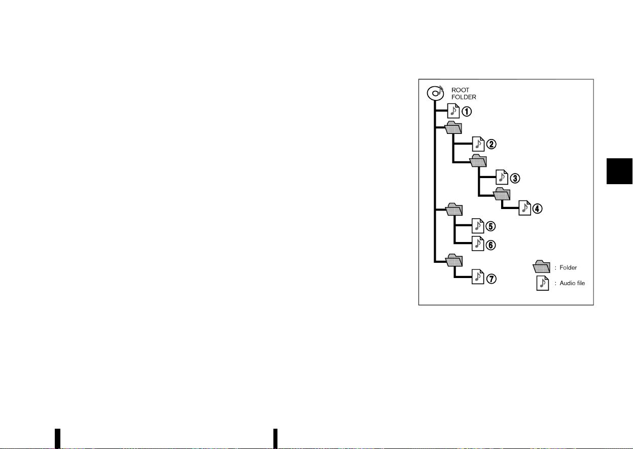
(219,1)
USB device with MP3/WMA/AAC
MEVT33A1-D8DC2645-EB1C-47B0-98FF-29DF02203ACE
Terms:
* MP3 — MP3 is short for Moving Pictures
Experts Group Audio Layer 3. MP3 is the most
well known compressed digital audio file
format. This format allows for near “CD quality”
sound, but at a fraction of the size of normal
audio files. MP3 conversion of an audio track
from CD can reduce the file size by approxi-
mately 10:1 ratio (Sampling: 44.1 kHz, Bit rate:
128 kbps) with virtually no perceptible loss in
quality. MP3 compression removes the redun-
dant and irrelevant parts of a sound signal
that the human ear doesn’t hear.
* WMA — Windows Media Audio (WMA) is a
compressed audio format created by Micro-
soft as an alternative to MP3. The WMA codec
offers greater file compression than the MP3
codec, enabling storage of more digital audio
tracks in the same amount of space when
compared to MP3s at the same level of quality.
This product is protected by certain intellec-
tual property rights of Microsoft Corporation
and third parties. Use or distribution of such
technology outside of this product is prohib-
ited without a licence from Microsoft or an
authorised Microsoft subsidiary and third par-
ties.
* AAC — Advanced Audio Coding (AAC) is a
compressed audio format. AAC offers greater
file compression than MP3 and enables music
file creation and storage at the same quality as
MP3.
* Bit rate — Bit rate denotes the number of bits
per second used by a digital music files. The
size and quality of a compressed digital audio
file is determined by the bit rate used when
encoding the file.
* Sampling frequency — Sampling frequency is
the rate at which the samples of a signal are
converted from analog to digital (A/D conver-
sion) per second.
* Multisession — Multisession is one of the
methods for writing data to media. Writing
data once to the media is called a single
session, and writing more than once is called a
multisession.
* ID3/WMA Tag — The ID3/WMA tag is the part of
the encoded MP3 or WMA file that contains
information about the digital music file such as
song title, artist, album title, encoding bit rate,
track time duration, etc. ID3 tag information is
displayed on the Album/Artist/Track title line
on the display.
* Windows® and Windows Media® are registered
trademarks and/or trademarks of Microsoft Cor-
poration in the United States of America and/or
other countries.
Playback order:
MSAA2494
Music playback order of the USB device with MP3/
WMA/AAC is as illustrated above.
* The folder names not containing MP3/WMA/
AAC files are not shown in the display.
* If there is a file in the top level of the device,
Root Folder is displayed.
Monitor, heater, air conditioner, audio and phone systems 215

(220,1)
216 Monitor, heater, air conditioner, audio and phone systems
* The playback order is the order in which the
files were written by the writing software, so
the files might not play in the desired order.
Specification chart:
Supported media
USB2.0
Supported file systems
ISO9660 LEVEL1, ISO9660 LEVEL2, Romeo, Joliet
* ISO9660 Level 3 (packet writing) is not supported.
* Files saved using the Live File System Component (on a Windows Vista-based computer)
are not supported.
Supported versions*1
MP3
Version
MPEG1, MPEG2
Sampling frequency
8 kHz - 48 kHz
Bit rate
32 kbps - 448 kbps, VBR*4
WMA*3
Version
WMA7, WMA8, WMA9, WMA9 Pro (except WMA9 Lossless, WMA9 Voice)
Sampling frequency
8 kHz - 48 kHz
Bit rate
5 kbps - 320 kbps, VBR*4
AAC
Version
MPEG4 – AAC
Sampling frequency
8 kHz - 48 kHz
Bit rate
32 kbps - 192 kbps, VBR*4
Tag information (Song title and Artist name)
ID3 tag VER1.0, VER1.1, VER2.2, VER2.3, VER2.4 (MP3 only)
WMA tag (WMA only)
Folder levels
Folder levels: 8, Folders: 2500 (including root folder), Files: 32000
Displayable character codes*2
01: ASCII, 02: ISO-8859-1, 03: UNICODE (UTF-16 BOM Big Endian), 04: UNICODE (UTF-16 Non-
BOM Big Endian), 05: UNICODE (UTF-8), 06: UNICODE (Non-UTF-16 BOM Little Endian)
*1 Files created with a combination of 48 kHz sampling frequency and 64 kbps bit rate cannot be played.
*2 Available codes depend on what kind of media, versions and information are going to be displayed.
*3 Protected WMA files (DRM) cannot be played.

(221,1)
*4 When VBR files are played, the playback time may not be displayed correctly. WMA7 and WMA8 are not applied to VBR.
Troubleshooting guide:
Symptom
Cause and Countermeasure
Cannot play
USB device was inserted incorrectly.
Check if there is condensation inside the player, and if there is, wait until the condensation is gone (about 1 hour) before using the
player.
If there is a mixture of music files and compressed audio files on a USB device, only the music files will be played.
Files with extensions other than “.MP3”, “.WMA”, “.M4A”, “.mp3”, “.wma” or “.m4a” cannot be played. In addition, the character codes and
number of characters for folder names and file names should be in compliance with the specifications.
Check if the USB device is protected by copyright.
It takes a relatively long time before
the music starts playing.
If there are many folder or file levels on the MP3/WMA/AAC files, some time may be required before the music starts playing.
If there are many folder or file levels on the USB device, some time may be required before the music starts playing.
Music cuts off or skips
The writing software and hardware combination might not match, or the writing speed, writing depth, writing width, etc., might not
match the specifications of the system. Try using the slowest writing speed.
Skipping with high bit rate files
Skipping may occur with large quantities of data, such as for high bit rate data.
Move immediately to the next song
when playing.
When a non-MP3/WMA/AAC file has been given an extension of “.MP3”, “.WMA”, “.M4A”, “.mp3”, “.wma” or “.m4a” when play is prohibited
by copyright protection, the player will skip to the next song.
The songs do not play back in the
desired order.
The playback order is the order in which the files were written by the writing software, so the files might not play in the desired order.
Random/Shuffle may be active on the audio system or on a USB device.
Monitor, heater, air conditioner, audio and phone systems 217
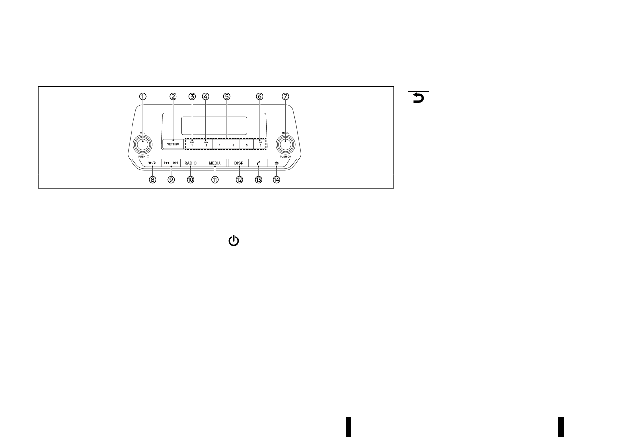
(222,1)
218 Monitor, heater, air conditioner, audio and phone systems
FM-AM RADIO WITH USB (Universal Serial Bus) CONNECTION PORT
MEVT33A1-CC10B709-D297-45B1-AE90-86306F820E64
MWAE0149X
1. Power/VOL (Volume) dial
2. <SETTING> button
3. <RPT> (Repeat) button
4. <MIX> button
5. Station memory buttons
6. <A-Z> button
7. OK/MENU dial
8. Day/Night button
9. Seek/Track button
10. <RADIO> button
11. <MEDIA> button
12. <DISP> (Display) button
13. Phone button
14. Back button
Audio main operation
MEVT33A1-B79BE1E2-5B79-4A26-97F0-D61DFAE46728
The audio system operates when the ignition
switch is placed in the ON or ACC position.
Power/VOL dial:
Power ON/OFF
To turn on the audio system, push the Power/VOL
dial.
The system will turn on in the mode, which was
used immediately before the system was turned
off.
To turn off the audio system, push the Power/VOL
dial.
Volume control
To control the volume, turn the Power/VOL dial.
Turn the Power/VOL dial clockwise to make the
sound louder.
Turn the Power/VOL dial anticlockwise to make
the sound quieter.
Back button:
Push to return to the previous screen.
<SETTING> button:
To configure [Audio], [Clock], [Radio] or [Language]
settings, perform the following procedure:
1. Push the <SETTING> button.
2. Turn the OK/MENU dial clockwise or antic-
lockwise. The display changes in the following
order:
[Audio] ⇔ [Clock] ⇔ [Radio] ⇔ [Language]
3. Push the OK/MENU dial to select the item.
After making the setting adjustments, push the
Back button repeatedly or push the <SETTING>
button.
Audio adjustments:
Push the <SETTING> button to display the setup
menu screen. Turn the OK/MENU dial to highlight
the [Audio] key and then push the OK/MENU dial.
The mode can be changed as follows by turning
the OK/MENU dial:
[Sound] ⇔ [Speed Vol.] ⇔ [Bass Boost] ⇔ [Audio
Reset]
Push the OK/MENU dial to select the highlighted
menu.
Turn the OK/MENU dial clockwise or anticlockwise
to adjust the following items and push the OK/
MENU dial to confirm.

(223,1)
Sound menu
Bass:
Use this control to enhance or attenuate bass
response sound.
Treble:
Use this control to enhance or attenuate the
treble.
Bal.:
Use this control to adjust the balance of the
volume between the left and right speakers.
Fade:
Use this control to adjust the balance of the
volume between the front and the rear speakers.
Speed Vol. menu
This mode controls the volume output from the
speakers automatically in relation to vehicle speed.
Adjusting the setting to OFF turns off the speed
volume feature.
Bass Boost menu
Turn on or off the Bass Boost feature which
emphasizes the lower audio frequencies.
Clock setting:
Push the <SETTING> button to display the setup
menu screen. Turn the OK/MENU dial to highlight
the [Clock] key and then push the OK/MENU dial.
Turn the OK/MENU dial, and the mode will change
as follows:
[Set Time] ⇔ [ON/OFF] ⇔ [Format]
Set Time
Select [Set Time] then adjust the clock as follows:
The hour display will start flashing. Turn the OK/
MENU dial to adjust the hour and push the OK/
MENU dial. The minute display will start flashing.
Turn the OK/MENU dial to adjust the minute and
push the OK/MENU dial to finish the clock adjust-
ment.
ON/OFF
The clock display setting can be turned on and off.
When the setting is turned on, the clock will be
displayed. (The clock will keep being displayed
even after the power of the audio unit is turned
off.) When the setting is turned off, the clock will
not be displayed.
Format
Switch the clock display between 24-hour clock
mode and 12-hour clock mode.
The clock may also be set in the vehicle informa-
tion display. See “[Clock]” (P.86).
Radio setting:
Push the <SETTING> button to display the setup
menu screen. Turn the OK/MENU dial to highlight
the [Radio] key and then push the OK/MENU dial.
Use the OK/MENU dial to select a mode.
[TA]
Use this control to switch Traffic Announcements
on or off when the unit starts.
Turn the OK/MENU dial clockwise or anticlockwise
to select then push the OK/MENU dial to confirm.
DAB Interrupt (where fitted)
Switch on or off specific listed Digital Interruptions.
When selected the Digital Audio Broadcasting
(DAB) radio stations will be interrupted if a specific
message is available.
Turn the OK/MENU dial clockwise or anticlockwise
to adjust then push the OK/MENU dial to select.
[Ref. DAB List] (where fitted)
Select this mode to manually update the DAB
station list.
Press the OK/MENU dial to start the search of the
stations. A confirmation message appears. In a
short period of time the stations are updated and
the last station (if possible) starts playing.
[Ref. FM list]
Select this mode to refresh the FM station list.
[EPG] (where fitted)
Electronic Programme Guide (EPG) for DAB is
designed to offer similar features for the user as
television EPG, but for radio and associated data
services, for example:
* display of schedules with programmes and
events
* searching through current and future pro-
grammes lists
Intellitext (where fitted)
Intellitext messages are a special format of DL
(Dynamic Label) messages that provide data like
sport or news.
Language setting:
Push the <SETTING> button to display the setup
menu screen. Turn the OK/MENU dial to highlight
the [Language] key and then push the OK/MENU
dial.
Monitor, heater, air conditioner, audio and phone systems 219

(224,1)
220 Monitor, heater, air conditioner, audio and phone systems
Select the appropriate language and push the OK/
MENU dial. Upon completion, the screen will
automatically adapt the language setting.
Day/Night button:
Push the Day/Night button to switch the display
brightness between the daytime and nighttime
modes.
The buttons on the audio unit will also illuminate in
the nighttime mode.
<MEDIA> button:
Push the <MEDIA> button to play a compatible
device when it is connected.
Each time the <MEDIA> button is pushed, the audio
source will change as follows:
[USB/iPod] ? [BT Audio] ? [USB/iPod]
The source that are not available will be skipped.
Phone button:
See “Bluetooth® Hands-Free Phone System (where
fitted)” (P.226).
Radio operation
MEVT33A1-282014B8-11B8-428F-8351-3C0C9EF3B0CC
The audio system operates when the ignition
switch is placed in the ON or ACC position.
Frequency range and step change:
To change the frequency range and step specifi-
cation of the radio, perform the following opera-
tions.
1. Turn on the audio system.
2. Push the <RADIO> button and select AM or FM
mode.
3. Push and hold the <SETTING> button for more
than 3 seconds.
4. After 3 seconds, keep holding the <SETTING>
button and turn the OK/MENU dial anticlock-
wise until you hear 3 clicks, clockwise until you
hear 3 clicks, and then anticlockwise until you
hear 3 clicks.
5. Turn the OK/MENU dial until [Region] is high-
lighted, and push the OK/MENU dial.
6. Select an appropriate region and push the OK/
MENU dial.
7. To apply the setting, turn off the audio system,
place the ignition switch in the “OFF” position.
Then, once open and close the driver’s door,
and keeping the door closed, wait for more
than 2 minutes. After that, open and close the
door, and place the ignition switch in the "ON"
position.
If the frequency range and step specification
cannot be changed, it is recommended to contact
a NISSAN dealer or qualified workshop.
<RADIO> button:
When the <RADIO> button is pushed while another
audio source is playing, the other audio source will
turn off and the radio will turn on.
To change the radio bands, push the <RADIO>
button until the desired band appears.
For models with DAB:
FM 1 ? FM 2 ? DAB1 ? DAB2 ? AM ? FM 1
For models without DAB:
FM 1 ? FM 2 ? AM ? FM 1
Pushing and holding the RADIO button will update
the station lists.
Seek/Track button:
Push the Seek/Track button briefly to manually
change the frequency.
To adjust the broadcasting station frequency
automatically, push and hold the Seek/Track
button. When the system detects a broadcasting
station, it will stop at the station.
FM mode:
Pushing the Seek/Track button starts the tuning
mode. A short push of the button will increase or
decrease the frequency a single step. Pushing the
button longer will activate the seek mode. The
radio tuner seeks from low to high or high to low
frequencies and stops at the next broadcasting
station. During seek mode, the audio output is
muted. If no broadcasting station can be found
within the complete band cycle, it will return to the
initial frequency.
DAB mode:
Push the Seek/Track button to select the next or
previous station. A long press triggers seek by
ensemble.
&
1
&
2
&
3
&
4
&
5
&
6
Station memory buttons:
During radio reception, pushing the station mem-

(225,1)
ory button for less than 2 seconds will select the
stored radio station.
For models with DAB
The audio system can store up to 12 FM station
frequencies (6 in each of FM 1 and FM 2), 6 AM
station frequencies and 12 DAB station frequencies
(6 in each of DAB 1 and DAB 2).
For models without DAB
The audio system can store up to 12 FM station
frequencies (6 in each of FM 1 and FM 2) and 6 AM
station frequencies.
To store the station frequency manually:
1. Tune to the desired broadcasting station
frequency.
2. Push and hold a station memory button
&
1
-
&
6
until a beep sounds.
3. The station memory number will be displayed,
indicating that the memory is stored properly.
4. Perform steps 1 - 3 for all other memory
buttons.
Radio Data System (RDS) OPERATION (where
fitted):
The RDS is a system through which encoded
digital information is transmitted by FM radio
stations in addition to the normal FM radio broad-
casting. The RDS provides information services
such as station name, traffic information, or news.
Digital Audio Broadcast (where fitted):
DAB (Digital Audio Broadcasting) is a standard for
digital radio broadcast.
Various information selected by the driver (Travel,
Warning, News, Weather, Sport, etc.) can be re-
ceived and will be provided to the driver.
Occasionally, in areas of poor DAB signal strength,
the full station name in the DAB List and DAB main
screen might be distorted. In this situation it may
still be possible to listen to the particular radio
station, at a reduced level of sound quality, but this
is not always possible.
NOTE:
* When in DAB mode, operation is similar to
FM mode but may slightly differ.
* In some countries or regions, some of these
services may not be available.
Alternative Frequency (AF) mode:
The AF mode operates in the FM (radio) mode.
* The AF mode operates in the FM (radio), and
will continue to operate in the background if
any media source is selected.
* The AF function compares signal strengths
and selects the station with the optimum
reception conditions for the currently tuned-
in station.
Programme Service (PS) FUNCTION (station
name display function):
* FM:
When an RDS station is tuned in with seek or
manual tuning, the RDS data is received and
the PS name is displayed.
* DAB:
When a station is tuned in with seek or manual
tuning, the data is received and the PS name is
displayed.
TA (Traffic announcement):
This function operates in FM/DAB (Radio) mode.
This function will still operate in the background if
any media source is selected.
Traffic announcement interrupt function:
When a traffic announcement is received, the
announcement is tuned in and the display shows
a notification message with the radio station
name. Once the traffic announcement has fin-
ished, the unit returns to the source that was
active before the traffic announcement started.
If the Back button is pushed during a traffic
announcement, the traffic announcement inter-
rupt mode is cancelled. The TA mode returns to
the standby mode and the audio unit returns to
the previous source.
USB (Universal Serial Bus) CONNECTION PORT
MEVT33A1-0C1B3131-4FFA-4E3A-96CD-7F1A7D929A9F
USB device main operation:
The USB connection port is located on the lower
part of the instrument panel. See “USB (Universal
Serial Bus) connection port” (P.224). Connect a USB
memory device into the USB connection port. The
USB memory device will be activated automati-
cally.
Refer to your device manufacturer’s owner infor-
mation regarding the proper use and care of the
device.
If the system has been turned off while the USB
memory device was playing, pushing the Power/
VOL dial will start the USB memory device.
Monitor, heater, air conditioner, audio and phone systems 221
(226,1)
222 Monitor, heater, air conditioner, audio and phone systems
<MEDIA> button:
To operate the USB memory device, push the
<MEDIA> button repeatedly until the USB mode is
selected.
List view:
While the track is being played, push the OK/MENU
dial to display the available tracks in a listed view
mode. To select a track from the list, turn the OK/
MENU dial and then push the OK/MENU dial.
Quick search:
In the list view mode, a quick search can be
performed to find a track from the list. Push the
<A-Z> button, turn the OK/MENU dial to the first
alphabetic letter of the song title and then push
the OK/MENU dial. When found, a list of the
available songs will be displayed. Select a preferred
track and push the OK/MENU dial to play the track.
Seek/Track button:
Push and hold the Seek/Track button to fast
forward or rewind through the track. When the
button is released, the track will play at normal
playing speed.
Track up/down:
Pushing the Seek/Track button once, the track will
skip forward to the next track or backward to the
beginning of the current track. Push the Seek/
Track button more than once to skip through the
tracks.
Folder browsing:
To select a preferred folder:
1. Push the OK/MENU dial and then push the
Back button to display a list of folders.
2. Turn the OK/MENU dial to highlight the pre-
ferred folder.
3. Push the OK/MENU dial to access the folder.
4. Push the OK/MENU dial again to start playing
the first track in the selected folder. To select
another track in the folder, turn the OK/MENU
dial until a preferred track is highlighted and
then push the OK/MENU dial.
If the currently selected folder contains sub folders,
push the OK/MENU dial and a new screen with a
list of sub folders will be displayed. Turn the OK/
MENU dial and then push the OK/MENU dial to
select a sub folder. Select the root folder item
when songs are recorded additionally in the root
folder.
To return to the previous folder screen, push the
Back button.
<RPT> button:
Push the <RPT> button and the current track will
be played continuously.
<MIX> button:
Push the <MIX> button and all the tracks in the
selected folder will be played in a random order.
<DISP> button:
While a track with recorded music information tags
(ID3-tags) is being played, the title of the played
track is displayed.
When the <DISP> button is pushed repeatedly,
further information about the track can be dis-
played along with the track title as follows:
[Track time] ? [Artist] ? [Album] ? [Track time]
Track details:
Pushing and holding the <DISP> button will turn
the display into a detailed overview. Push the Back
button to return to the display for the main display
mode.
iPod PLAYER OPERATION
MEVT33A1-B9210394-D769-4231-ACBF-E9158BD1B4C7
Connecting iPod:
The USB connection port is located on the lower
part of the instrument panel. See “USB (Universal
Serial Bus) connection port” (P.224).
When the iPod is connected to the vehicle, the iPod
music library can only be operated by the vehicle
audio controls.
If your iPod supports charging via a USB connec-
tion, its battery will be charged while connected to
the vehicle with the ignition switch in the ON
position.
Compatibility:
The system unit shall be compatible with all
devices (past and future) supporting Apple Acces-
sory Protocol on USB link.
It includes (and not limited to):
(227,1)
* iPod touch 5th (iOS 9.3.5)
* iPhone 7 Plus (iOS 10.1.1, 11.0.3, 11.1.2)
* iPhone 8 (iOS 11.2)
* iPhone 8 Plus (iOS 11.2.5)
* iPhone X (iOS 11.2, 12.0.1)
NOTE:
This audio system does not support iPad char-
ging.
<MEDIA> button:
To operate the iPod, push the <MEDIA> button
repeatedly until the USB/iPod mode is selected
and then push the OK/MENU dial.
List view:
While the track is being played, push the OK/MENU
dial to display the iPod menu.
iPod MAIN OPERATION:
Interface:
The interface for iPod operation shown on the
audio system display is similar to the iPod inter-
face. Use the OK/MENU dial to play a track on the
iPod.
The following items can be chosen from the menu
list screen.
* [Playlists]
* [Artists]
* [Albums]
* [Songs]
* [More...]
For further information about each item, see the
iPod owner’s manual.
Quick search:
In the list view mode, a quick search can be
performed to find a track from the list. Push the
<A-Z> button, turn the OK/MENU dial to the first
alphabetic letter of the song title and then push
the OK/MENU dial. When found, a list of the
available songs will be displayed. Select a preferred
track and push the OK/MENU dial to play the track.
Seek/Track button:
Push and hold the Seek/Track button to fast
forward or rewind through the track. When the
button is released, the track will play at normal
playing speed.
Track up/down:
Pushing the Seek/Track button once, the track will
skip forward to the next track or backward to the
beginning of the current track. Push the Seek/
Track button more than once to skip through the
tracks.
<RPT> button:
Push the <RPT> button and the current track/
folder will be played continuously.
<MIX> button:
Push the <MIX> button and all the tracks in the
selected playlist will be played in a random order.
<DISP> button:
While a track with recorded music information tags
(ID3-tags) is being played, the title of the played
track is displayed.
When the <DISP> button is pushed repeatedly,
further information about the track can be dis-
played along with the track title as follows:
[Track time] ? [Artist] ? [Album] ? [Track time]
Track details:
Pushing and holding the <DISP> button will turn
the display into a detailed overview. To return to
the main display, push the Back button.
Bluetooth® AUDIO PLAYER OPERATION
MEVT33A1-24EB5878-DD1E-4649-A1E0-2A268E8F1903
Regulatory information:
Bluetooth® is a trademark owned
by Bluetooth SIG, Inc. and li-
censed to Visteon Corporation.
NOTE:
The audio system only supports Bluetooth®
devices with AVRCP (Audio Video Remote Con-
trol Profile) version 1.3, or 1.0 or earlier.
Bluetooth® AUDIO PLAYER MAIN OPERATION:
To play Bluetooth® audio, the Bluetooth® audio
device needs to be paired to the in-vehicle system.
See “Setting items” (P.228).
<MEDIA> button:
To operate the Bluetooth® audio streaming, push
the <MEDIA> button repeatedly until [BT Audio] is
shown.
The type of display shown on the audio system
Monitor, heater, air conditioner, audio and phone systems 223
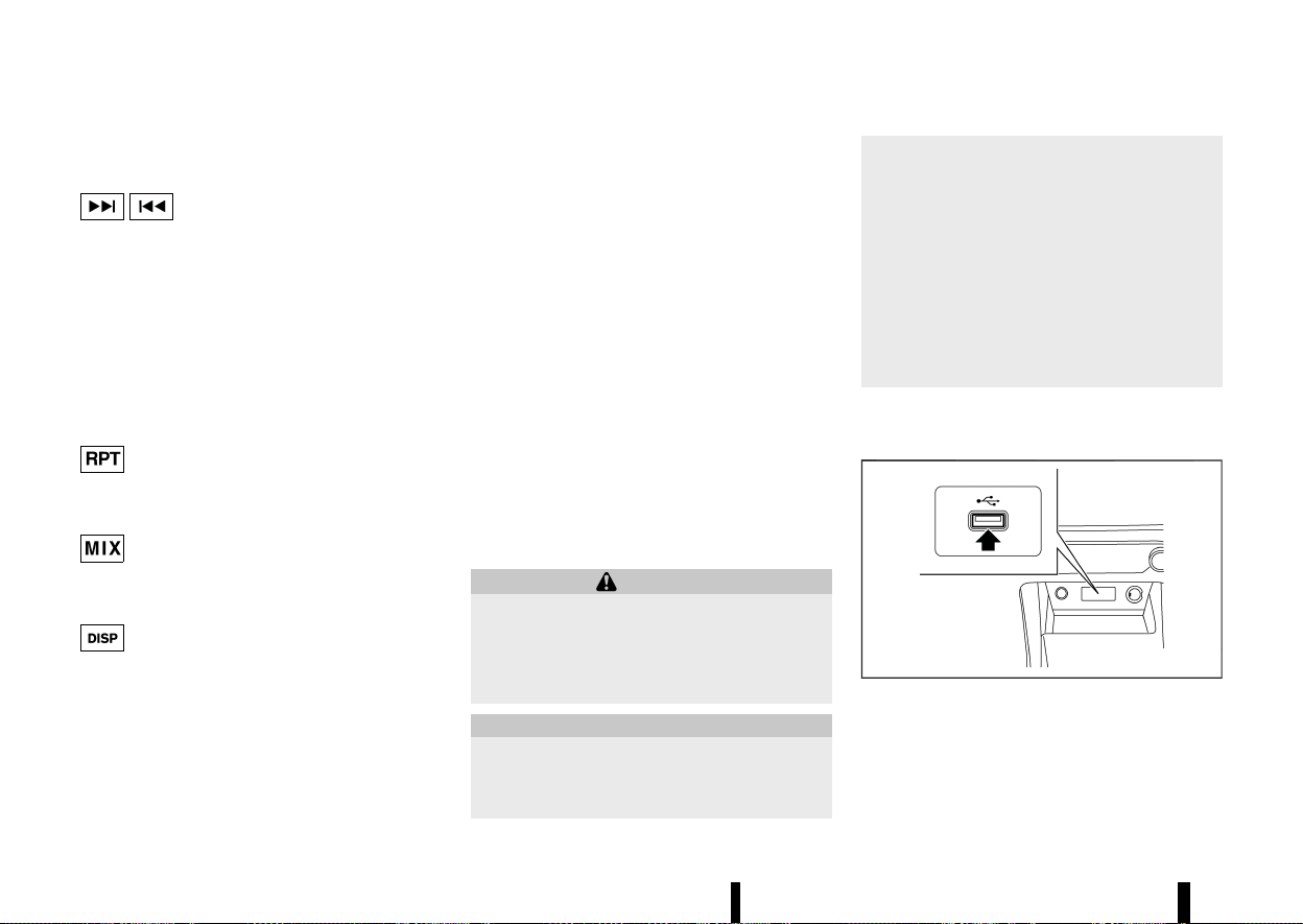
(228,1)
224 Monitor, heater, air conditioner, audio and phone systems
can vary depending on the Bluetooth® version of
the device.
Seek/Track button:
Push and hold the Seek/Track button to fast
forward or rewind through the track. When the
button is released, the track will play at normal
playing speed.
Track up/down:
Pushing the Seek/Track button once, the track will
skip forward to the next track or backward to the
beginning of the current track. Push the Seek/
Track button more than once to skip through the
tracks.
<RPT> button:
Push the <RPT> button and the current track/
folder will be played continuously.
<MIX> button:
Push the <MIX> button and all the tracks in the
selected playlist will be played in a random order.
<DISP> button:
While a track with recorded music information tags
(ID3-tags) is being played, the title of the played
track is displayed.
When the <DISP> button is pushed repeatedly,
further information about the track can be dis-
played along with the track title.
Track details:
Pushing and holding the <DISP> button will turn
the display into a detailed overview. To return to
the main display, push the Back button.
OK/MENU dial:
When the OK/MENU dial is pushed while operating
Bluetooth® audio, the following menus will be
available. (Available menus may vary depending
on the connected device.) Use the OK/MENU dial to
highlight and select a preferred menu.
[Playlists]
An interface similar to the one on the connected
iPod is displayed.
[Radio]
This menu is displayed only when iPhone is
connected. Radio stations downloaded to the
iPhone via music app are displayed.
USB (Universal Serial Bus) CONNECTION
PORT
MEVT33A1-DDE8EC51-917D-4AE6-9DE9-45D1D711E60E
WARNING
Do not connect, disconnect or operate the USB
device while driving. Doing so can be a dis-
traction. If distracted you could lose control of
your vehicle and cause an accident or serious
injury.
CAUTION
* Do not force the USB device into the USB
connection port. Inserting the USB device
tilted or up-side-down into the USB con-
nection port may damage the USB con-
nection port. Make sure that the USB
device is connected correctly into the USB
connection port.
* Do not grab the USB connection port cover
(where fitted) when pulling the USB device
out of the USB connection port. This could
damage the USB connection port and the
USB connection port cover (where fitted).
* Do not leave the USB cable in a place
where it can be pulled unintentionally.
Pulling the cable may damage the USB
connection port.
Refer to your device manufacturer’s owner infor-
mation regarding the proper use and care of the
device.
MWAE0882X
The USB connection port is located on the lower
part of the instrument panel. Insert USB devices or
iPod connectors into this port.
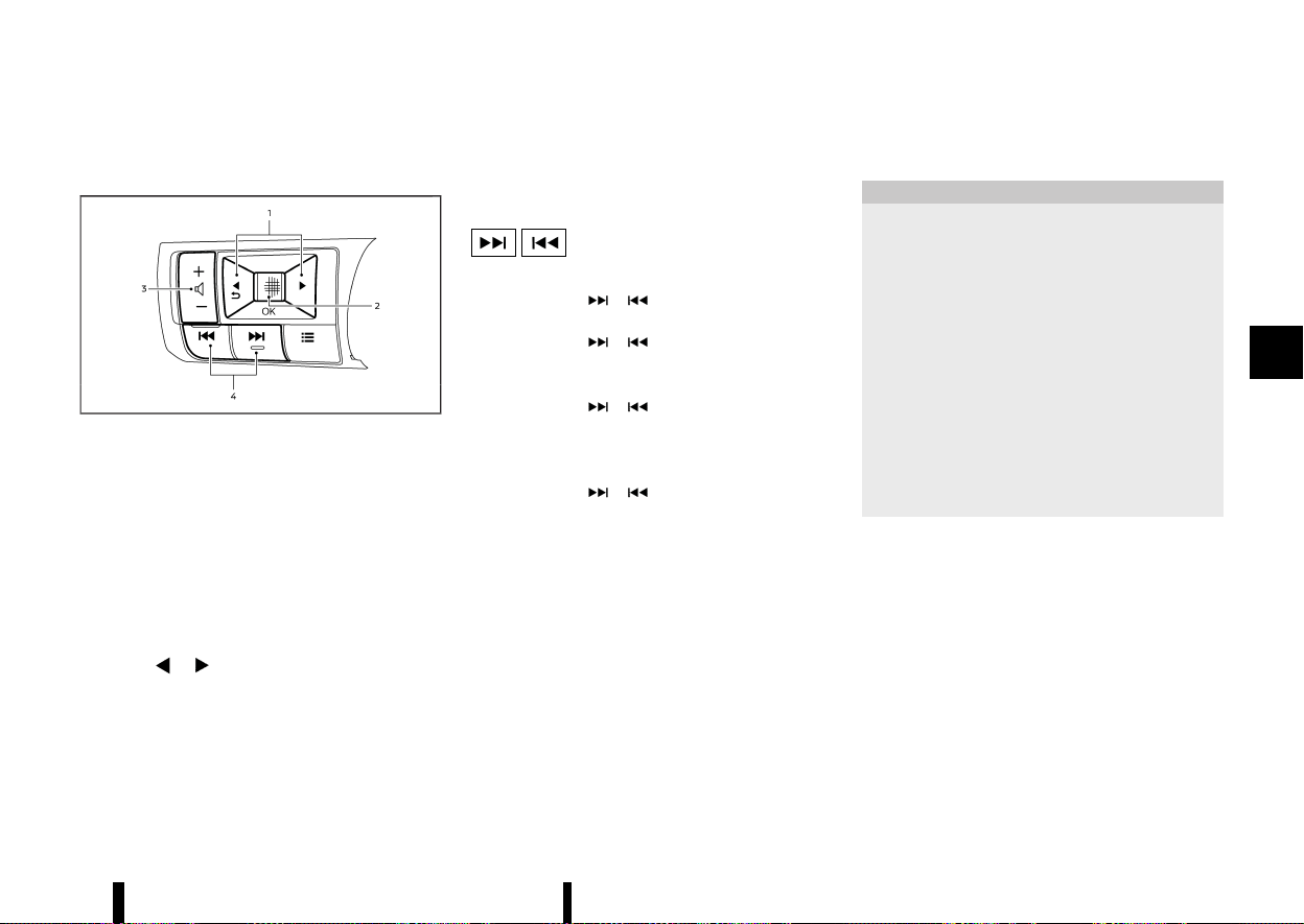
(229,1)
STEERING-WHEEL-MOUNTED CON-
TROLS FOR AUDIO
MEVT33A1-41981ECB-7687-4D9C-9B99-B9724805F703
MWAE0687X
1. Menu control buttons
2. Scroll dial
3. Volume control button
4. Seek/Track buttons
The audio system can be operated using the
controls on the steering wheel. Some functions
may not be available depending on the connected
audio device and other conditions.
Menu control buttons/scroll dial
MEVT33A1-6D6316DD-C24A-4A51-B017-90C42643B934
Push the / buttons and switch the vehicle
information display to the audio mode. Push the
scroll dial to display available audio source menus.
Scroll the scroll dial to highlight a preferred audio
source and then push it to select the audio source.
Volume control button
MEVT33A1-F025A515-EDBF-48B2-8296-768B2DCE9B92
Push the + or − side of the button to increase or
decrease the volume.
Seek/Track buttons
MEVT33A1-7DDD50A0-4BE6-4ED4-A229-4F3D7B6CA32A
* RADIO
— Pushing
/ shorter
Next or previous station
— Pushing
/ longer
Next or previous available preset station
* USB device, iPod or Bluetooth® audio
— Pushing
/ shorter
Next track or the beginning of the current
track (the previous track if the button is
pushed immediately after the current track
starts playing)
— Pushing
/ longer
Forward or rewind
USB DEVICE CARE
MEVT33A1-AF4F4D49-16AB-49DE-9190-60DC93958277
* Do not touch the terminal portion of the USB
device.
* Do not place heavy objects on the USB device.
* Do not store the USB device in highly humid
locations.
* Do not expose the USB device to direct sun-
light.
* Do not spill any liquids on the USB device.
Refer to the USB device Owner’s Manual for the
details.
MEVT33A1-E2DAEAFF-6B29-45EC-AEF9-457A39885BCD
The antenna is located on the rear part of the
vehicle roof.
CAUTION
* A build up of ice on the antenna can affect
radio performance. Remove the ice to
restore radio reception.
* When removing snow from the roof, do not
apply strong force to the antenna. That
may cause broken the antenna and roof
panel dent.
* When using a high pressure car wash, keep
the high pressure nozzle away from the
antenna. The seal may be deformed or
damaged.
* The radio performance may be affected if
cargo carried on the roof blocks the radio
signal. If possible, do not put cargo near
the antenna.
Monitor, heater, air conditioner, audio and phone systems 225
RADIO ANTENNA
RADIO ANTENNA

(230,1)
226 Monitor, heater, air conditioner, audio and phone systems
MEVT33A1-433608FE-D4D9-4693-ADC1-026C2CCCF895
When installing a car phone or a CB radio in your
vehicle, be sure to observe the following precau-
tions, otherwise the new equipment may adversely
affect the electronic control modules and electro-
nic control system harness.
WARNING
* A mobile phone should not be used for any
purpose while driving so full attention may
be given to vehicle operation. Some jur-
isdictions prohibit the use of mobile
phones while driving.
* If you must make a call while your vehicle
is in motion, the hands-free mobile phone
operational mode (where fitted) is highly
recommended. Exercise extreme caution
at all times so full attention may be given
to vehicle operation.
* If a conversation in a moving vehicle
requires you to take notes, pull off the
road to a safe location and stop your
vehicle before doing so.
CAUTION
* Keep the antenna as far away as possible
from the electronic control modules.
* Keep the antenna wire more than 20 cm (8
in) away from the electronic control sys-
tem harness. Do not route the antenna
wire next to any harness.
* Adjust the antenna standing-wave ratio as
recommended by the manufacturer.
* Connect the ground wire from the CB radio
chassis to the body.
* For details, it is recommended you visit a
NISSAN dealer or qualified workshop.
MEVT33A1-82D02A04-6737-45EF-9A7E-CD163F2E47BC
Models with NissanConnect System:
Refer to the separate NissanConnect Owner’s
Manual.
WARNING
* Use a phone after stopping your vehicle in
a safe location. If you have to use a phone
while driving, exercise extreme caution at
all times so full attention may be given to
vehicle operation.
* If you find yourself unable to devote full
attention to vehicle operation while using
the phone, pull off the road to a safe
location and stop your vehicle before
doing so.
CAUTION
To avoid draining the vehicle battery, use a
phone after starting the engine.
Bluetooth® is a wireless radio communication
standard. This system offers a hands-free facility
for your mobile phone to enhance driving comfort.
To use the Bluetooth® Hands-Free Phone System,
your mobile phone must first be setup. See
“Bluetooth® settings” (P.227). Once it has been
setup, the hands-free mode is automatically acti-
vated on the registered mobile phone (via
Bluetooth®) when it comes into range.
A notification message appears on the audio
display when the phone is connected, when an
incoming call is being received, as well as when a
call is initiated.
When a call is active, the audio system, micro-
CAR PHONE OR CB RADIO
CAR PHONE OR CB RADIO
Bluetooth® HANDS-FREE
PHONE SYSTEM (where fitted)
Bluetooth® HANDS-FREE
PHONE SYSTEM (where fitted)
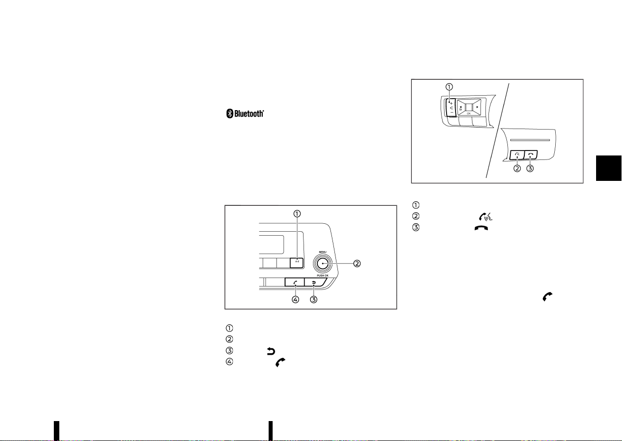
(231,1)
phone, and steering-wheel-mounted control but-
tons enable hands-free communication.
If the audio system is in use at the time, the radio,
iPod, USB audio or Bluetooth® audio will be muted
and will stay muted until the active call has ended.
The Bluetooth® system may not be able to
connect with your mobile phone for the following
reasons:
* The mobile phone is too far away from the
vehicle.
* The Bluetooth® mode on your mobile phone
has not been activated.
* Your mobile phone has not been paired with
the Bluetooth® system of the audio unit.
* The mobile phone does not support
Bluetooth® technology.
NOTE:
* For details, see your mobile phone’s Owner’s
Manual.
* For assistance with your mobile phone
integration, visit a NISSAN dealer or qualified
workshop.
REGULATORY INFORMATION
MEVT33A1-2F1BF736-F6CD-4742-9449-67C7809AB0C7
Bluetooth® TRADEMARK
MEVT33A1-BD45643D-ABF6-4AC6-8160-A47031380553
Bluetooth® is a trademark owned
by Bluetooth SIG, Inc. and li-
censed to Visteon Corporation.
NOTE:
The system only supports Bluetooth® devices
with AVRCP (Audio Video Remote Control Profile)
version 1.3, or 1.0 or earlier.
CONTROL BUTTONS AND MICROPHONE
MEVT33A1-DA00BA54-3259-4618-B350-04387445020F
Instrument panel:
MWAE0141X
<A-Z> button
OK/MENU dial
Back button
Phone button
Steering-wheel-mounted control:
MWAE0688X
Example
Volume control button
PHONE SEND button
PHONE END button
Microphone:
Microphone is located near the map light.
Bluetooth® SETTINGS
MEVT33A1-87C2CF01-CB9A-43E4-8FF3-7188D1D779DC
Pairing device
MEVT33A1-F5C68208-60A1-4F49-8CBE-3CFE32FD62A6
Enter the phone setup menu via the button
on the instrument panel, select the [Bluetooth] key,
and then check if the Bluetooth® is set to on. (Use
the OK/MENU dial to turn it on.)
To setup the Bluetooth® system to pair (connect or
register) your preferred mobile phone, follow the
following procedure.
1. To pair a device, use the [Scan devices] key or
the [Pair device] key on the display. See
“Setting items” (P.228).
Monitor, heater, air conditioner, audio and phone systems 227
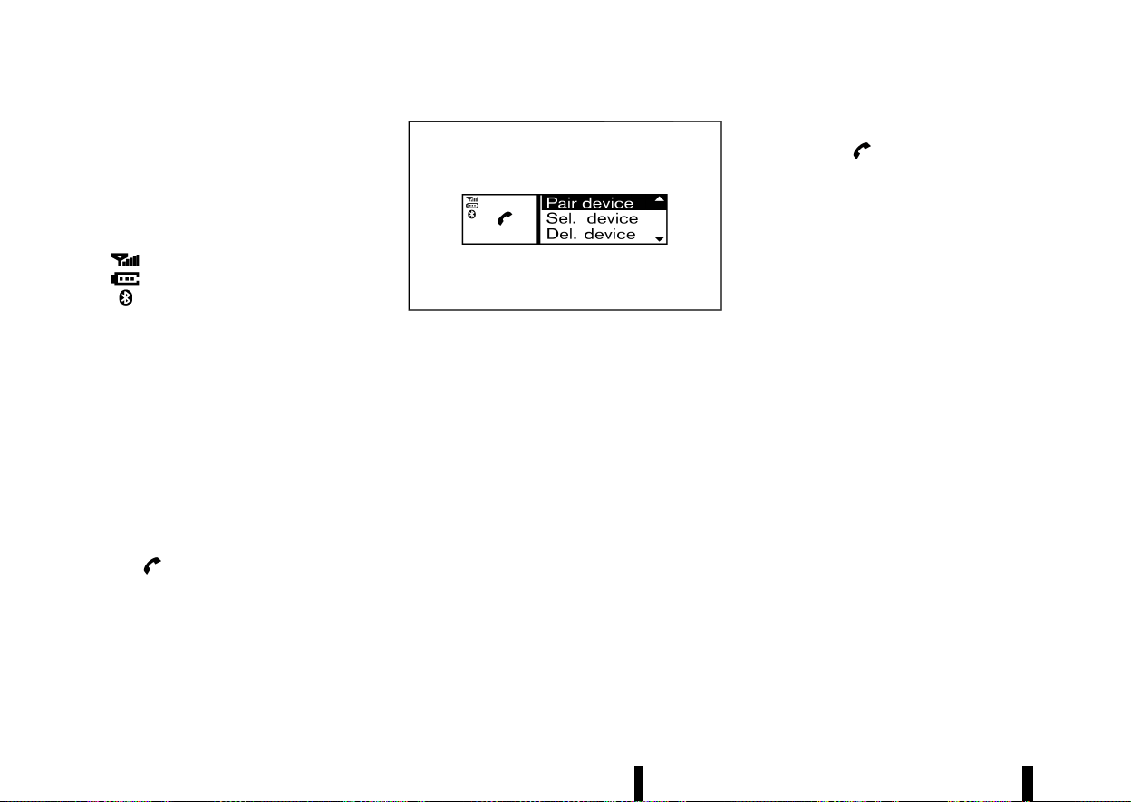
(232,1)
228 Monitor, heater, air conditioner, audio and phone systems
2. A notification message will be displayed when
the phone is successfully paired.
3. The display will return to the current audio
source status after the connection is com-
plete.
* While the Bluetooth® connection is active, the
following icons will appear on the display.
—
: Signal strength indicator
—
: Battery status indicator*
—
: Bluetooth® connection ON indicator
*: If low battery is indicated, the Bluetooth®
device must be recharged soon.
* Up to 5 different Bluetooth® devices can be
connected. However, only one device can be
used at a time. If 5 different Bluetooth®
registered devices are registered, a new device
can only replace one of the 5 existing paired
devices.
* The pairing procedure and operation may vary
according to device type and compatibility.
See the Bluetooth® device Owner’s Manual for
further details.
Setting items
MEVT33A1-CE1576C4-9064-4B98-9838-1C40360779B3
To set up the Bluetooth® system with a device,
push the
button on the instrument panel.
The phone menu will be displayed.
MJVH0847X
Available items:
* [Scan devices]
A list of detected Bluetooth® devices is dis-
played.
* [Pair device]
Bluetooth® devices can be paired with the
system. A maximum of 5 Bluetooth® devices
can be registered.
* [Sel. device]
Paired Bluetooth® devices are listed and can
be selected for connection.
* [Del. device]
A registered Bluetooth® device can be deleted.
* [Settings]
Phone setting menus are available. See “Gen-
eral settings” (P.232).
* [Bluetooth]
If this setting is turned off, the connection
between the Bluetooth® devices and the in-
vehicle Bluetooth® module will be cancelled.
[Scan devices]:
1. Push the
button on the instrument
panel. Select the [Scan devices] key. The audio
unit searches for the Bluetooth® devices and
shows all devices that were found.
Make sure your Bluetooth® device is available
at this time.
2. Select the device to be paired using the OK/
MENU dial.
3. The pairing procedure depends on the device
to be connected:
a. Device without PIN code:
The Bluetooth® connection will be automati-
cally connected without any further input.
b. Device with PIN code:
Two different ways of pairing are possible
depending on the device:
.
Type A:
The message [To Pair] and [Enter Pin 0000]
will be displayed.
Confirm the PIN code on the device. The
Bluetooth® connection will be made.
.
Type B:
The message [Pairing request] and [Confirm
password] together with a 6–digit code will
be displayed. The unique and identical code
should be displayed on the device. If the
code is identical confirm on the device.
The Bluetooth® connection will be made.
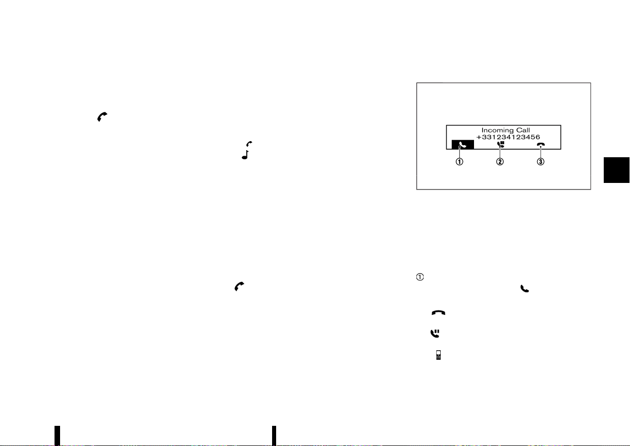
(233,1)
[Pair device]:
1. Turn on the Bluetooth® on the audio unit. See
“[Bluetooth]” (P.229).
2. Use the audio unit to pair:
Push the
button on the instrument
panel. Select the [Pair device] key.
The pairing procedure depends on the
Bluetooth® device to be connected:
a. Device without PIN code:
The Bluetooth® connection will be automati-
cally connected without any further input.
b. Device with PIN code:
Two different ways of pairing are possible
depending on the device. See “[Scan devices]”
(P.228).
3. Use the Bluetooth® audio/mobile phone de-
vice to pair:
a. Switch on the search mode for Bluetooth®
devices.
If the search mode finds the audio unit, it will
be shown on the device display.
b. Select the unit device shown as [My Car].
c. If required, enter the number code shown
on the relevant device with the device’s
own keypad, and push the confirmation
key on the Bluetooth® device.
The operation may vary depending on the
Bluetooth® devices.
Refer to the relevant Bluetooth® device Owner’s
Manual for further details.
[Sel. device]:
The paired device list shows which Bluetooth®
audio or mobile phone devices have been paired or
registered to the system. Select the appropriate
device to connect to the system.
The following symbols (where fitted) indicate the
capability of the registered device:
*
: Mobile phone integration
*
: Audio streaming (A2DP – Advanced Audio
Distribution Profile)
[Del. device]:
A registered device can be removed from
Bluetooth® system registration. Select a registered
device and push the OK/MENU dial to confirm the
deletion.
[Bluetooth]:
The Bluetooth® setting can be turned on and off,
using the OK/MENU dial.
USING THE SYSTEM
MEVT33A1-192EDD00-58E2-4D09-99A0-468F312E4B49
The hands-free mode can be operated using the
button on the instrument panel.
Receiving a call
MEVT33A1-D6C3BCEB-1FB7-45EA-B62A-B60B20748FE7
MJVH0857X
When receiving an incoming call, the display on the
audio unit will show the caller’s phone number (or
a notification message that the caller’s phone
number cannot be shown) and operation icons
as illustrated. To highlight different icons, turn the
OK/MENU dial. Push the OK/MENU dial to select
the highlighted icon.
Answering and operations during a call:
Answer the call by selecting “
”.
During the call, the following icons are available:
*
:
Select this item to end the call.
*
:
Select this item to put the call on hold.
*
:
Select this item to transfer the call from the
hands-free phone system to your mobile
phone.
Monitor, heater, air conditioner, audio and phone systems 229
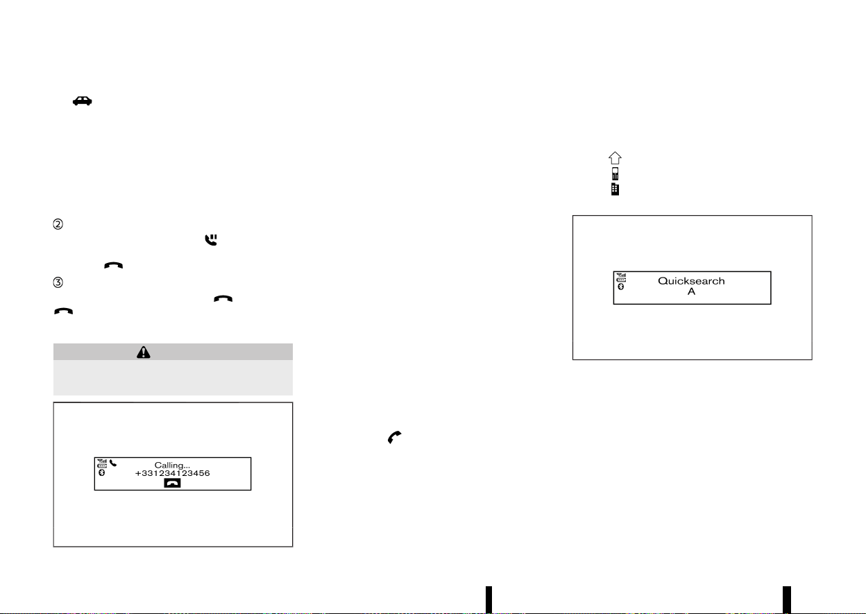
(234,1)
230 Monitor, heater, air conditioner, audio and phone systems
* :
Select this item to transfer the call back to the
hands-free phone system from the mobile
phone.
* #123:
Select this item to enter numbers during a call.
For example, use this function when directed
by an automated phone system to dial an
extension number.
Putting a call on hold:
To put a call on hold, select “
”. Push the OK/
MENU dial again to take the call. To reject the call,
select the
button on the steering wheel.
Rejecting a call:
To reject an incoming call, select “
” or push the
button on the steering wheel.
Initiating a call
MEVT33A1-8EFB9872-8733-448E-ADBF-7E9620350923
WARNING
Park the vehicle in a safe location, and apply
the parking brake before making a call.
MWAE0163X
A call can be initiated using one of the following
methods:
* Making a call from the phonebook
* Manually dialling a phone number
* Redialing
* Using call history
— [Outgoing]
— [Incoming]
— [Missed]
Making a call from the phonebook:
Once the Bluetooth® connection has been made
between the registered mobile phone and the
hands-free phone system, phonebook data will be
transferred automatically to the hands-free phone
system. The transfer may take a while before
completion.
NOTE:
Phonebook data will be erased when:
* Switching to another registered mobile
phone.
* Mobile phone is disconnected.
* The registered mobile phone is deleted from
the audio system.
1. Push the
button on instrument panel.
2. Turn the OK/MENU dial to highlight [Phone-
book] and push the OK/MENU dial.
3. Scroll down through the list, select the appro-
priate contact name (highlighted), and push
the OK/MENU dial.
4. The screen will show the number to be dialled.
Push the OK/MENU dial to dial the number.
If more than one number is registered, select
an appropriate icon.
.
: Home
.
: Mobile phone
.
: Office
Quick searching the phonebook
MJVH0858X
The quick search mode can be used as follows:
1. Push the <A-Z> button.
2. Turn the OK/MENU dial for the first alphabetic
or numerical letter of the contact name. Once
highlighted, push the OK/MENU dial to select
the letter.
3. The display will show the corresponding con-
tact name(s). Where necessary, use the OK/
MENU dial to scroll further for the appropriate
contact name to call.
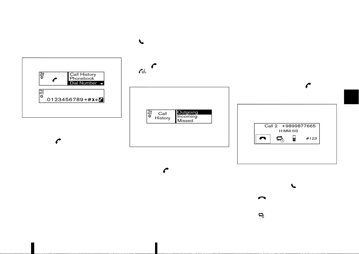
(235,1)
4. The screen will show the number to be dialled.
Push the OK/MENU dial to dial the number.
Manually dialling a phone number:
MWAE0158X
To dial a phone number manually, perform the
following operation:
1. Push the
button on the instrument
panel and turn the OK/MENU dial to highlight
[Dial Number].
2. Push the OK/MENU dial to select [Dial Number].
3. Turn the OK/MENU dial to scroll along and
highlight each number of the phone number.
Push the OK/MENU dial to select the high-
lighted number.
To delete the last number entered, scroll to the
“/” (Backspace symbol) and once highlighted,
push the OK/MENU dial. The last number will
be deleted. Pushing the OK/MENU dial repeat-
edly will delete each subsequent number.
4. After entering the last number, scroll to the
“
” symbol and push the OK/MENU dial to dial
the number.
Redialing:
To redial or call the last number dialled, push and
hold the
button on the instrument panel or
the
button on the steering wheel for more
than 2 seconds.
Using call history:
MWAE0159X
A number from the dialled, received, or missed call
lists can also be used to make a call.
1. Push the
button on the instrument
panel and select [Call History] on the display.
2. Turn the OK/MENU dial and scroll to an item,
and push the OK/MENU dial to select an item.
Available items
.
[Outgoing]
Use the dialled call mode to make a call
which is based on the list of outgoing
(dialled) calls.
.
[Incoming]
Use the received call mode to make a call
which is based on the list of received calls.
.
[Missed]
Use the missed call mode to make a call
which is based on the list of missed calls.
3. Scroll to the preferred phone number and
push the OK/MENU dial or
button on
the instrument panel.
Second incoming call
MEVT33A1-A85BA6A9-B48A-4691-AD40-8EADCF4707B8
MWAE0164X
Whenever there is a second incoming call, opera-
tion icons for the second incoming call are shown
in the display. By selecting “
”, the call is accepted
and the current call is put on hold.
Selecting “
” using the OK/MENU dial rejects the
second incoming call. When this is done during the
conversation, it ends the call.
Selecting “
” using the OK/MENU dial switches
Monitor, heater, air conditioner, audio and phone systems 231
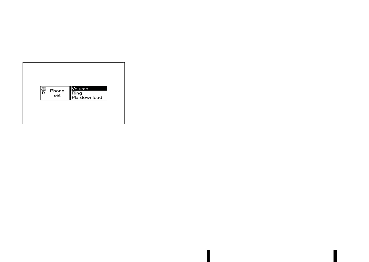
(236,1)
232 Monitor, heater, air conditioner, audio and phone systems
the call on line between the first and the second
call.
General settings
MEVT33A1-2779D031-08D0-4AD8-84E8-893BAB5A4DB0
MWAE0142X
Using the OK/MENU dial, select [Settings] from the
phone menu.
Volume settings and manually downloading the
phonebook can be done using this menu.
Menu operation:
Turn the OK/MENU dial to change the highlighted
item and to change the volume settings.
Push the OK/MENU dial to select the highlighted
item and to apply the setting.
Menu items:
* [Volume]
— [Ring]
Set the phone ringing volume.
— [Call]
Set the volume of the conversation during a
call.
* [Ring]
— [Vehicle]
Switch the ringtone to ring from the vehicle
or the mobile phone.
— [Phone]
Switch the phone ringing volume on or off.
* [PB download]
Download the phonebook of the mobile device
to the audio unit manually.

(237,1)
5 Starting and driving
Running-in schedule ................................................................................. 237
Before starting engine ............................................................................ 237
Precautions when starting and driving ..................................... 237
Exhaust gas (carbon monoxide) ........................................... 238
Three-way catalyst .......................................................................... 238
Petrol Particulate Filter (PPF) (where fitted) ................ 239
Turbocharger system .................................................................... 240
Tyre Pressure Monitoring System (TPMS) ..................... 240
On-pavement and off-road driving precautions ............... 242
Off-road recovery .............................................................................. 242
Driving safety precautions ......................................................... 243
Care when driving ...................................................................................... 244
Engine cold start period .............................................................. 244
Loading luggage ................................................................................ 244
Driving in wet conditions ............................................................ 244
Driving in winter conditions ..................................................... 244
Push-button ignition switch ............................................................... 245
Precautions on push-button ignition
switch operation ................................................................................ 245
Intelligent Key system ................................................................... 245
Operating range ................................................................................. 245
Push-button ignition switch positions ............................ 245
Emergency engine shut off ...................................................... 246
Intelligent Key battery discharge ......................................... 246
Starting the engine .................................................................................... 247
Drive Mode Selector .................................................................................... 248
SPORT mode ........................................................................................... 249
STANDARD mode ................................................................................. 249
ECO mode ................................................................................................. 249
Driving the vehicle ........................................................................................ 250
Continuously Variable Transmission (CVT) .................... 250
Stop/Start System ........................................................................................ 255
Retrograde movement control function .......................... 258
Stop/Start System display ........................................................... 258
Stop/Start OFF switch .................................................................... 260
Driver Assistance systems ...................................................................... 261
How to enable/disable the systems .................................... 265
Common troubleshooting guide ............................................ 267
Traffic Sign Recognition (TSR) ............................................................. 271
System operation ................................................................................ 271
How to enable/disable the TSR system ........................... 273
System temporarily unavailable .............................................. 273
System malfunction .......................................................................... 273
System maintenance ....................................................................... 273
Lane Departure Warning (LDW) (where fitted) ....................... 274
LDW system operation .................................................................... 274
How to enable/disable the LDW system .......................... 275
LDW system limitations .................................................................. 276
System temporarily unavailable .............................................. 276
System malfunction .......................................................................... 277

(238,1)
System maintenance ..................................................................... 277
Intelligent Lane Intervention (where fitted) ........................... 277
Intelligent Lane Intervention
system operation .............................................................................. 279
How to enable/disable the Intelligent Lane
Intervention system ........................................................................ 279
Intelligent Lane Intervention
system limitations ............................................................................ 280
System temporarily unavailable ............................................ 281
System malfunction ........................................................................ 282
System maintenance ..................................................................... 282
Emergency Lane Assist (ELA) system (where fitted) ......... 282
ELA system operation ................................................................... 283
How to enable/disable the ELA system .......................... 284
ELA system limitations .................................................................. 285
System temporarily unavailable ............................................ 287
System malfunction ........................................................................ 288
System maintenance ..................................................................... 288
Blind Spot Warning (BSW) (where fitted) .................................. 289
BSW system operation .................................................................. 290
How to enable/disable the BSW system ........................ 291
BSW system limitations ................................................................ 291
BSW driving situations .................................................................. 292
System temporarily unavailable ............................................ 293
System malfunction ........................................................................ 294
System maintenance ..................................................................... 294
Intelligent Blind Spot Intervention (where fitted) .............. 295
Intelligent Blind Spot Intervention
system operation .............................................................................. 297
How to enable/disable the Intelligent Blind Spot
Intervention system ........................................................................ 298
Intelligent Blind Spot Intervention
system limitations .............................................................................. 298
Intelligent Blind Spot Intervention
driving situations ................................................................................. 300
System temporarily unavailable .............................................. 303
System malfunction .......................................................................... 303
System maintenance ....................................................................... 303
Rear Cross Traffic Alert (RCTA) (where fitted) ........................ 304
RCTA system operation ................................................................. 305
How to enable/disable the RCTA system ....................... 306
RCTA system limitations ............................................................... 307
System temporarily unavailable .............................................. 308
System malfunction .......................................................................... 308
System maintenance ....................................................................... 308
Speed limiter (where fitted) ................................................................... 309
Speed limiter operations ............................................................... 309
Cruise control (where fitted) ................................................................ 311
Precautions on cruise control .................................................. 311
Cruise control operations ............................................................. 312
Intelligent Cruise Control (ICC) (where fitted) ......................... 313
How to select the cruise control mode ............................ 315
Vehicle-to-vehicle distance control mode ...................... 315
Conventional (fixed speed) cruise
control mode .......................................................................................... 326
ProPILOT Assist (where fitted) ............................................................ 329
ProPILOT Assist system operation ........................................ 330
ProPILOT Assist switches .............................................................. 332
ProPILOT Assist system display and indicators .......... 333
Turning the conventional (fixed speed) cruise control
mode ON .................................................................................................... 334
Operating ProPILOT Assist .......................................................... 335

(239,1)
How to enable/disable the Steering Assist .................. 338
How to cancel the ProPILOT Assist system ................. 339
Intelligent Cruise Control (ICC) ............................................... 339
Steering Assist ..................................................................................... 351
Conventional (fixed speed) cruise
control mode ........................................................................................ 356
Intelligent Emergency Braking with Pedestrian
Detection system ........................................................................................ 359
Intelligent Emergency Braking with Pedestrian
Detection system operation ..................................................... 360
Turning the Intelligent Emergency Braking with
Pedestrian Detection system ON/OFF ............................. 362
Intelligent Emergency Braking with Pedestrian
Detection system limitations ................................................... 363
System temporarily unavailable ............................................ 367
System malfunction ........................................................................ 368
System maintenance ..................................................................... 368
Intelligent Forward Collision Warning ......................................... 369
Intelligent Forward Collision Warning
system operation .............................................................................. 370
Turning the Intelligent Forward Collision Warning
system ON/OFF .................................................................................. 371
Intelligent Forward Collision Warning
system limitations ............................................................................ 372
System temporarily unavailable ............................................ 374
System malfunction ........................................................................ 374
System maintenance ..................................................................... 375
Intelligent Driver Alertness (where fitted) ................................ 375
Intelligent Driver Alertness system operation ............ 376
How to enable/disable the Intelligent Driver
Alertness system ............................................................................... 376
Intelligent Driver Alertness system limitations .......... 377
System malfunction .......................................................................... 377
Rear Automatic Braking (RAB) (where fitted) ......................... 377
RAB system operation .................................................................... 378
Turning the RAB system ON/OFF .......................................... 379
RAB system limitations ................................................................... 380
System malfunction .......................................................................... 381
System maintenance ....................................................................... 381
Fuel Efficient Driving Tips ....................................................................... 382
Increasing fuel economy and reducing Carbon
Dioxide emissions .......................................................................................... 383
Smart simple hybrid system ................................................................ 383
Regeneration .......................................................................................... 384
Torque assist function .................................................................... 384
Parking ................................................................................................................... 384
Trailer towing ................................................................................................... 386
Operating precautions .................................................................... 386
Tyre pressure .......................................................................................... 386
Safety chains .......................................................................................... 386
Trailer brakes .......................................................................................... 386
Trailer detection (where fitted) ................................................ 386
Trailer Sway Control ......................................................................... 387
Coupling device installation (for Europe) ......................... 388
Electric power steering ............................................................................. 389
Brake system .................................................................................................... 389
Braking precautions .......................................................................... 389
Brake assist .............................................................................................. 390
Anti-lock Braking System (ABS) ............................................... 390
Vehicle Dynamic Control (VDC)/Electronic Stability
Programme (ESP) system ....................................................................... 391
How to turn off the VDC/ESP system ................................ 392
Brake Force Distribution ................................................................ 392

(240,1)
Chassis control .............................................................................................. 393
Intelligent Trace Control ............................................................. 393
Intelligent Ride Control ................................................................. 394
Hill Start Assist system ........................................................................... 394
Parking sensor (sonar) system ......................................................... 395
System operation .............................................................................. 396
Turning on and off the parking sensor
(sonar) function .................................................................................. 397
Parking sensor (sonar) system limitations ................... 398
System temporarily unavailable ............................................ 399
System maintenance ..................................................................... 399
Cold weather driving
....
............................................................................ 400
Freeing a frozen door lock
....
.................................................... 400
Anti-freeze
....
.......................................................................................... 400
Battery
....
................................................................................................... 400
Draining of coolant water
....
...................................................... 400
Tyre equipment
....
.............................................................................. 400
Special winter equipment
....
...................................................... 400
Driving on snow or ice
....
.............................................................. 400
Active noise cancellation/Active
sound enhancement
....
............................................................................ 401
Active noise cancellation
....
........................................................ 402
Active sound enhancement
....
................................................. 402

(241,1)
MEVT33A1-EC2FD794-8914-4CC0-A38E-2BDC09CE9FF5
CAUTION
During the first 2,000 km (1,200 miles), follow
these recommendations to obtain maximum
engine performance and ensure the future
reliability and economy of your new vehicle.
Failure to follow these recommendations may
result in shortened engine life and reduced
engine performance.
* Avoid driving for long periods at constant
speed, either fast or slow. Do not run the
engine over 4,000 rpm.
* Do not accelerate at full throttle in any gear.
* Avoid quick starts.
* Avoid hard braking as much as possible.
* Do not tow a trailer for at least the first 800 km
(500 miles).
MEVT33A1-D2C912EA-DD64-408F-847E-861ADAEFE53E
WARNING
The driving characteristics of your vehicle will
change remarkably by any additional load and
its distribution, as well as by adding optional
equipment (roof racks, etc.). Your driving style
and speed must be adjusted according to the
circumstances. Especially when carrying heavy
loads, your speed must be reduced ade-
quately.
* Make sure the area around the vehicle is clear.
* Visually inspect tyres for their appearance and
condition. Measure and check the tyre pres-
sure for proper inflation.
* Check that all windows and lights are clean.
* Adjust the seat and head restraint positions.
* Adjust the inside and outside rearview mirror
positions.
* Fasten your seat belt and ask all passengers to
do the same.
* Check that all doors are closed.
* Check the operation of the warning lights
when the ignition switch is placed in the ON
position.
* Maintenance items in the “8. Maintenance and
do-it-yourself” section should be checked
periodically.
MEVT33A1-39D24DF9-F51E-4E79-ABE4-371E6635EA26
WARNING
* Do not leave children or adults who would
normally require the support of others
alone in your vehicle. Pets should not be
left alone either. They could accidentally
injure themselves or others through inad-
vertent operation of the vehicle. Also, on
hot, sunny days, temperatures in a closed
vehicle could quickly become high enough
to cause severe or possibly fatal injuries to
people or animals.
* Properly secure all cargo with ropes or
straps to help prevent it from sliding or
shifting. Do not place cargo higher than
the seatbacks. In a sudden stop or colli-
sion, unsecured cargo could cause perso-
nal injury.
NOTE:
During the first few months after purchasing a
new vehicle, if you smell strong odours of
Volatile Organic Compounds (VOCs) inside the
vehicle, ventilate the passenger compartment
thoroughly. Open all the windows before enter-
ing or while in the vehicle. In addition, when the
temperature in the passenger compartment
rises, or when the vehicle is parked in direct
sunlight for a period of time, turn off the air
recirculation mode of the air conditioner and/or
open the windows to allow sufficient fresh air
into the passenger compartment.
Starting and driving 237
RUNNING-IN SCHEDULE
RUNNING-IN SCHEDULE
BEFORE STARTING ENGINE
BEFORE STARTING ENGINE
PRECAUTIONS WHEN STARTING AND DRIVING
PRECAUTIONS WHEN STARTING AND DRIVING

(242,1)
238 Starting and driving
EXHAUST GAS (carbon monoxide)
MEVT33A1-78327FD6-CBB2-489F-9B79-07540BD8FF38
WARNING
* Do not breathe exhaust gas; it contains
colourless and odourless carbon monox-
ide. Carbon monoxide is dangerous. It can
cause unconsciousness or death.
* If you suspect that exhaust fumes are
entering the vehicle, drive with all windows
fully open, and have the vehicle inspected
immediately.
* Do not run the engine in closed spaces
such as a garage.
* Do not park the vehicle with the engine
running for an extended period of time.
* Keep the back door closed while driving,
otherwise exhaust gas could be drawn into
the passenger compartment. If you must
drive with the back door open, follow these
precautions:
— Open all the windows.
— Turn the air recirculation mode off and
set the fan speed control to the high-
est level to circulate the air.
* If a special body or other equipment is
added for recreational or other usage,
follow the manufacturer’s recommenda-
tion to prevent carbon monoxide entry
into the vehicle. (Some recreational vehicle
appliances such as stoves, refrigerators,
heaters, etc. may also generate carbon
monoxide.)
* If electrical wiring or other cable connec-
tions must pass to a trailer through the
seal on the back door or the body, follow
the manufacturer’s recommendation to
prevent carbon monoxide entry into the
vehicle.
* The exhaust system and body should be
inspected by a qualified mechanic when-
ever:
— Your vehicle is raised while being
serviced.
— You suspect that exhaust fumes are
entering into the passenger compart-
ment.
— You notice a change in the sound of
the exhaust system.
— You have had an accident involving
damage to the exhaust system, under-
body, or rear of the vehicle.
THREE-WAY CATALYST
MEVT33A1-7EE6B03F-AE0E-40F5-8BB5-AFD093FB5BD4
The three-way catalyst is an emission control
device installed in the exhaust system. Exhaust
gases in the three-way catalyst are burned at high
temperatures to help reduce pollutants.
WARNING
* The exhaust gas and the exhaust system
are very hot. Keep people, animals and
flammable materials away from the ex-
haust system components.
* Do not stop or park the vehicle over
flammable materials such as dry grass,
wastepaper or rags. They may ignite and
cause a fire.
CAUTION
* Do not use leaded petrol. Deposits from
leaded petrol will seriously reduce the
three-way catalyst’s ability to help reduce
exhaust pollutants.
* Keep your engine tuned up. Malfunctions
in the ignition, fuel injection, or electrical
systems can cause overrich fuel flow into
the three-way catalyst, causing it to over-
heat. Do not keep driving if the engine
misfires, or if noticeable loss of perfor-
mance or other unusual operating condi-
tions are detected. Have the vehicle
inspected. It is recommended you visit a
NISSAN dealer or qualified workshop for
this service.
* Avoid driving with an extremely low fuel
level. Running out of fuel could cause the
engine to misfire, damaging the three-way
catalyst.
* Do not race the engine while warming it
up.
* Do not push or tow your vehicle to start the
engine.
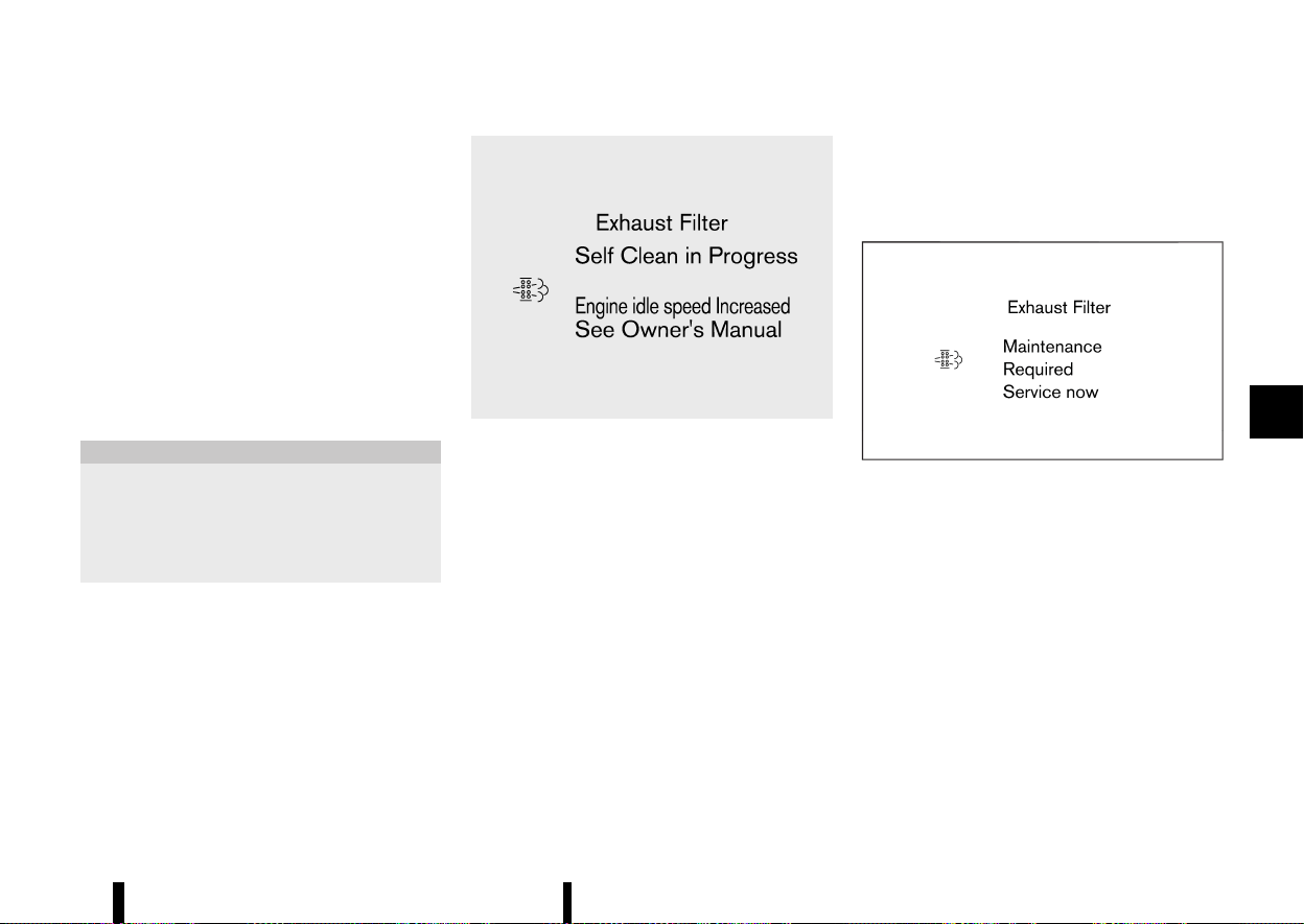
(243,1)
PETROL PARTICULATE FILTER (PPF)
(where fitted)
MEVT33A1-1450E74E-DFF0-4CD6-86BD-32502DDA9D6C
Your vehicle is equipped with a Petrol Particulate
Filter (PPF) as a part of the emission control
system.
The PPF filters carbon particles from the exhaust
gas, thus reducing the emission of soot to the
environment.
Under normal driving conditions, the accumulated
carbon particles in the PPF are burned-off reg-
ularly, thus emptying the filter from carbon parti-
cles. In this way, the PPF is “regenerated” and again
fully operational to filter the carbon particles from
the exhaust gas as intended.
CAUTION
* Under certain driving conditions, the PPF
may become saturated/clogged because
these driving conditions prevent auto-
matic regeneration of the filter. In this
case, a message appears in the vehicle
information display.
MWAF1289X
* When the [Exhaust Filter/Self Clean in Pro-
gress] message appears in the vehicle in-
formation display, provided that legal and
safety conditions allow, the vehicle should
be driven at a speed of over 60 km/h (37
MPH) until the message is no longer dis-
played.
* During the regeneration process, the engine
speed may increase and driveability may
change. You may also notice a change in the
sound of the exhaust system. However, this
is a normal behavior of the engine during
regeneration and does not indicate a mal-
function.
* When the [Exhaust Filter/Self Clean in Pro-
gress] message appears, Stop/Start system,
cruise control (where fitted), Intelligent
Cruise Control (where fitted) and ProPILOT
Assist (where fitted) system may be deacti-
vated.
If the vehicle continues to be driven with the
[Exhaust Filter/Self Clean in Progress] message
displayed, the GPF may become more saturated
and displayed message may change to [Exhaust
Filter/Maintenance Required Service now].
MWAF1290X
* When the [Exhaust Filter/Maintenance Re-
quired Service now] message appears in the
vehicle information display, always visit the
nearest NISSAN dealer or qualified workshop
as soon as possible. The Malfunction Indi-
cator Light (MIL) may also illuminate. Ex-
tended driving with the message displayed
and/or the MIL illuminated may lead to
damage to the exhaust filter system.
* When the [Exhaust Filter/Maintenance Re-
quired Service now] message appears in the
vehicle information display, cruise control
(where fitted), Intelligent Cruise Control
(where fitted) and ProPILOT Assist (where
fitted) system will be deactivated.
What you can do to prevent the GPF from
becoming saturated/clogged:
Starting and driving 239

(244,1)
240 Starting and driving
* Avoid repeated and frequent short journeys in
which the engine does not reach its normal
operating temperature.
* Regularly drive the vehicle at speeds over 60
km/h (37 MPH) for an extended period of time
(more than 30 minutes).
TURBOCHARGER SYSTEM
MEVT33A1-ED218B24-204B-4DA4-A93B-786F3ED16384
The turbocharger system uses engine oil for
lubrication and cooling of its rotating components.
The turbocharger turbine turns at extremely high
speeds and it can reach an extremely high
temperature. It is essential to maintain a clean
supply of oil flowing through the turbocharger
system. A sudden interruption of oil supply may
cause a malfunction in the turbocharger.
To ensure prolonged life and performance of the
turbocharger, it is essential to comply with the
following maintenance procedure.
CAUTION
* Change your engine oil according to the
recommended intervals shown in a sepa-
rate maintenance booklet.
* Use only the recommended engine oil. (See
“Recommended fluids/lubricants and ca-
pacities” (P.456).)
* If the engine has been operating at high
rpm for an extended period of time, let it
idle for a few minutes prior to turn off.
* Do not accelerate your engine to high rpm
immediately after starting it.
TYRE PRESSURE MONITORING SYSTEM
(TPMS)
MEVT33A1-70DEE521-236F-487A-BFBD-1A02741B58A6
Each tyre should be checked monthly when cold
and inflated to the inflation pressure recom-
mended by the vehicle manufacturer on the
vehicle placard or tyre inflation pressure label. (If
your vehicle has tyres of a different size than the
size indicated on the vehicle placard or tyre
inflation pressure label, you should determine the
proper tyre inflation pressure for those tyres.)
As an added safety feature, your vehicle has been
equipped with a Tyre Pressure Monitoring System
(TPMS) that illuminates a low tyre pressure telltale
when one or more of your tyres is significantly
under-inflated. Accordingly, when the low tyre
pressure telltale illuminates, you should stop and
check your tyres as soon as possible, and inflate
them to the proper pressure. Driving on a sig-
nificantly under-inflated tyre causes the tyre to
overheat and can lead to tyre failure. Under-
inflation also reduces fuel efficiency and tyre tread
life, and may affect the vehicle’s handling and
stopping ability.
Please note that the TPMS is not a substitute for
proper tyre maintenance, and it is the driver’s
responsibility to maintain correct tyre pressure,
even if under-inflation has not reached the level to
trigger illumination of the TPMS low tyre pressure
telltale.
Your vehicle has also been equipped with a TPMS
malfunction indicator to indicate when the system
is not operating properly. The TPMS malfunction
indicator is combined with the low tyre pressure
telltale. When the system detects a malfunction,
the telltale will flash for approximately one minute
and then remain continuously illuminated. This
sequence will continue upon subsequent vehicle
start-ups as long as the malfunction exists. When
the malfunction indicator is illuminated, the sys-
tem may not be able to detect or signal low tyre
pressure as intended. TPMS malfunctions may
occur for a variety of reasons, including the
installation of replacement or alternate tyres or
wheels on the vehicle that prevent the TPMS from
functioning properly. Always check the TPMS
malfunction telltale after replacing one or more
tyres or wheels on your vehicle to ensure that the
replacement or alternate tyres and wheels allow
the TPMS to continue to function properly.
Additional information
MEVT33A1-35DCC367-1FDE-400F-81C3-933ED5807016
* The TPMS will activate only when the vehicle is
driven at speeds above 25 km/h (16 MPH). Also,
this system may not detect a sudden drop in
tyre pressure (for example a flat tyre while
driving).
* The low tyre pressure warning light does not
automatically turn off when the tyre pressure
is adjusted. After the tyre is inflated to the
recommended pressure, reset the tyre pres-
sures registered in your vehicle and then drive
the vehicle at speeds above 25 km/h (16 MPH)
to activate the TPMS and turn off the low tyre
pressure warning light. Use a tyre pressure
gauge to check the tyre pressure.
* The [Low Tyre Pressure] warning appears in
the vehicle information display when the low
tyre pressure warning light is illuminated and
low tyre pressure is detected. The [Low Tyre

(245,1)
Pressure] warning turns off when the low tyre
pressure warning light turns off.
The [Low Tyre Pressure] warning does not
appear if the low tyre pressure warning light
illuminates to indicate a TPMS malfunction.
* Tyre pressure rises and falls depending on the
heat caused by the vehicle’s operation and the
outside temperature. Do not reduce the tyre
pressure after driving because the tyre pres-
sure rises after driving. Low outside tempera-
ture can lower the temperature of the air
inside the tyre which can cause a lower tyre
inflation pressure. This may cause the low tyre
pressure warning light to illuminate. If the
warning light illuminates in low ambient tem-
perature, check the tyre pressure for all four
tyres.
* Depending on a change in the outside tem-
perature, the low tyre pressure warning light
may illuminate even if the tyre pressure has
been adjusted properly. Adjust the tyre pres-
sure to the recommended COLD tyre pressure
again when the tyres are cold, and reset the
TPMS.
* You can also check the tyre pressure of all
tyres in the vehicle information display. (See
“Trip computer” (P.101).)
For additional information, see “Low tyre pressure
warning light” (P.77) and “Tyre Pressure Monitoring
System (TPMS)” (P.405).
WARNING
* If the low tyre pressure warning light
illuminates while driving, avoid sudden
steering manoeuvres or abrupt braking,
reduce vehicle speed, pull off the road to a
safe location and stop the vehicle as soon
as possible. Driving with under-inflated
tyres may permanently damage the tyres
and increase the likelihood of tyre failure.
Serious vehicle damage could occur and
may lead to an accident and could result in
serious personal injury. Check the tyre
pressure for all four tyres. Adjust the tyre
pressure to the recommended COLD tyre
pressure shown on the tyre placard to turn
the low tyre pressure warning light OFF. If
you have a flat tyre, repair it with an
emergency tyre puncture repair kit as soon
as possible. (See “Flat tyre” (P.405) for
repairing a flat tyre.)
* After adjusting the tyre pressure, be sure
to reset the TPMS. Otherwise, the TPMS will
not warn of low tyre pressure.
* Replacing tyres with those not originally
specified by NISSAN could affect the prop-
er operation of the TPMS.
* NISSAN recommends using only Genuine
NISSAN Emergency Tyre Sealant provided
with your vehicle. Other tyre sealants may
damage the valve stem seal which can
cause the tyre to lose air pressure. Visit a
NISSAN dealer or qualified workshop as
soon as possible after using tyre repair
sealant.
CAUTION
* The TPMS may not function properly when
the wheels are equipped with tyre chains
or the wheels are buried in snow.
* Do not place metalised film or any metal
parts (antenna, etc.) on the windows. This
may cause poor reception of the signals
from the tyre pressure sensors, and the
TPMS will not function properly.
Some devices and transmitters may temporarily
interfere with the operation of the TPMS and cause
the low tyre pressure warning light to illuminate.
Some examples are:
* Facilities or electric devices using similar radio
frequencies are near the vehicle.
* If a transmitter set to similar frequencies is
being used in or near the vehicle.
* If a computer (or similar equipment) or a DC/
AC converter is being used in or near the
vehicle.
Low tyre pressure warning light may illuminate in
the following cases.
* If the vehicle is equipped with a wheel and tyre
without TPMS.
* If the TPMS has been replaced and the ID has
not been registered.
* If the wheel is not originally specified by
NISSAN.
Starting and driving 241
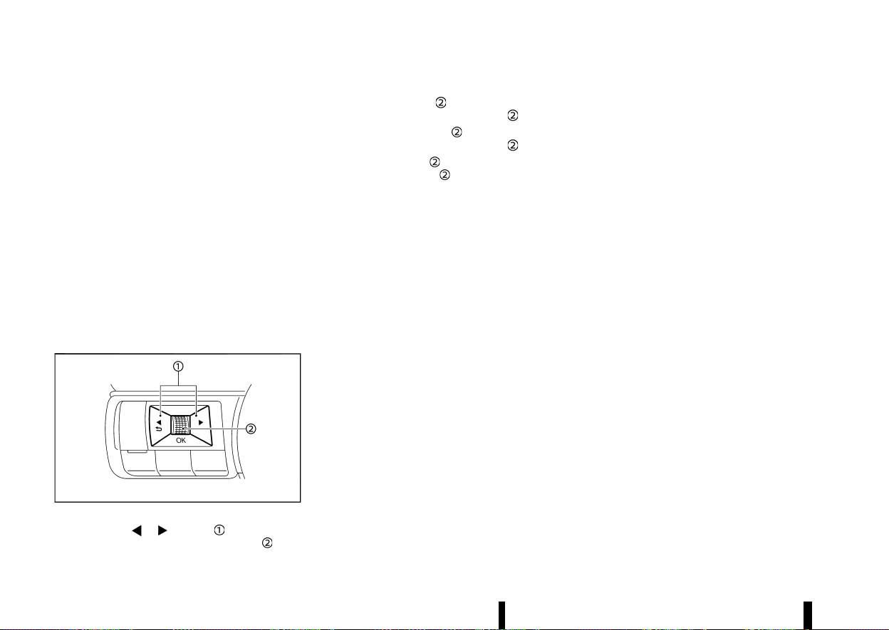
(246,1)
242 Starting and driving
TPMS resetting
MEVT33A1-97BF427F-D9B9-4C60-9001-C815F9FC9728
To keep the TPMS functioning properly, the reset
operation must be performed in the following
cases.
* when the tyre pressure is adjusted
* when a tyre or a wheel is replaced
* when the tyres are rotated
Perform the following procedures to reset the
TPMS.
1. Park the vehicle in a safe and level place.
2. Apply the parking brake and push the park
button to shift to the P (Park) position.
3. Adjust the tyre pressure on all four tyres to the
recommended COLD tyre pressure shown on
the tyre placard. Use a tyre pressure gauge to
check the tyre pressure.
4. Place the ignition switch in the ON position.
MWAF1161X
5. Press the button until [Settings]
appears and then push the scroll dial
.
6. Use the scroll dial
until [Tyre Pressures] is
selected, and press the scroll dial
.
7. Use the scroll dial
until [Calibrate] is
selected, and press the scroll dial
.
8. Use the scroll dial
until [Yes] is selected, and
press the scroll dial
to reset the TPMS.
9. After resetting the TPMS, drive the vehicle for
several minutes at speeds above 25 km/h (16
MPH).
If the low tyre pressure warning light illuminates
after the resetting operation, it may indicate that
the TPMS is not functioning properly. Have the
system checked by a NISSAN dealer or qualified
workshop.
For information regarding the low tyre pressure
warning light, see “Low tyre pressure warning light”
(P.77).
MEVT33A1-2C484A79-3F5C-4DFB-928B-EBA67B255769
Utility vehicles have a significantly higher roll-
over rate than other types of vehicles.
They have higher ground clearance than passen-
ger cars to make them capable of performing in a
variety of on-pavement and off-road applications.
This gives them a higher centre of gravity than
ordinary cars. An advantage of higher ground
clearance is a better view of the road, allowing
you to anticipate problems. However, they are not
designed for cornering at the same speeds as
conventional passenger cars any more than low-
slung sports cars are designed to perform satis-
factorily under off-road conditions. If at all possible,
avoid sharp turns or abrupt manoeuvres, particu-
larly at high speeds. As with other vehicles of this
type, failure to operate this vehicle correctly may
result in loss of control or vehicle rollover.
Be sure to read “Driving safety precautions” (P.243).
OFF-ROAD RECOVERY
MEVT33A1-0F533FD6-C994-442E-865A-E45B70DAFF19
If the right side or left side wheels leave the road
surface, maintain control of the vehicle by follow-
ing the procedure below. Please note that this
procedure is only a general guide. The vehicle must
be driven as appropriate based on the conditions
of the vehicle, road and traffic.
1. Remain calm and do not overreact.
2. Do not apply the brakes.
3. Maintain a firm grip on the steering wheel with
both hands and try to hold a straight course.
4. When appropriate, slowly release the accel-
erator pedal to gradually slow the vehicle.
ON-PAVEMENT AND OFF-ROAD
DRIVING PRECAUTIONS
ON-PAVEMENT AND OFF-ROAD
DRIVING PRECAUTIONS

(247,1)
5. If there is nothing in the way, steer the vehicle
to follow the road while the vehicle speed is
reduced. Do not attempt to drive the vehicle
back onto the road surface until vehicle speed
is reduced.
6. When it is safe to do so, gradually turn the
steering wheel until both tyres return to the
road surface. When all tyres are on the road
surface, steer the vehicle to stay in the
appropriate driving lane.
.
If you decide that it is not safe to return the
vehicle to the road surface based on
vehicle, road or traffic conditions, gradually
slow the vehicle to a stop in a safe place off
the road.
DRIVING SAFETY PRECAUTIONS
MEVT33A1-0BA35F18-2070-428E-9EBB-57A04344BFFA
Your vehicle is designed for both normal and off-
road use. However, avoid driving in deep water or
mud as your vehicle is mainly designed for leisure
use, unlike a conventional off-road vehicle.
Remember that Two-Wheel Drive (2WD) models are
less capable than Four-Wheel Drive (4WD) models
for rough road driving and extrication when stuck
in deep snow, mud, or the like.
Please observe the following precautions:
WARNING
* Drive carefully when off the road and avoid
dangerous areas. Every person who drives
or rides in this vehicle should be seated
with their seat belt fastened. This will keep
you and your passengers in position when
driving over rough terrain.
* Do not drive across steep slopes. Instead
drive either straight up or straight down
the slopes. Off-road vehicles can tip over
sideways much more easily than they can
forward or backward.
* Many hills are too steep for any vehicle. If
you drive up them, you may stall. If you
drive down them, you may not be able to
control your speed. If you drive across
them, you may roll over.
* Do not shift ranges while driving on down-
hill grades as this could cause loss of
control of the vehicle.
* Stay alert when driving to the top of a hill.
At the top there could be a drop-off or
other hazard that could cause an accident.
* If your engine stalls or you cannot make it
to the top of a steep hill, never attempt to
turn around. Your vehicle could tip or roll
over. Always back straight down in R
(Reverse) range. Never back down in N
(Neutral), using only the brake, as this
could cause loss of control.
* Heavy braking going down a hill could
cause your brakes to overheat and fade,
resulting in loss of control and an accident.
Apply brakes lightly and use a low range to
control your speed.
* Unsecured cargo can be thrown around
when driving over rough terrain. Properly
secure all cargo so it will not be thrown
forward and cause injury to you or your
passengers.
* To avoid raising the centre of gravity
excessively, do not exceed the rated capa-
city of the roof rack (where fitted) and
evenly distribute the load. Secure heavy
loads in the cargo area as far forward and
as low as possible. Do not equip the vehicle
with tyres larger than specified in this
manual. This could cause your vehicle to
roll over.
* Do not grip the inside or spokes of the
steering wheel when driving off-road. The
steering wheel could move suddenly and
injure your hands. Instead drive with your
fingers and thumbs on the outside of the
rim.
* Before operating the vehicle, ensure that
the driver and all passengers have their
seat belts fastened.
* Always drive with the floor mats in place as
the floor may became hot.
* Lower your speed when encountering
strong crosswinds. With a higher centre
of gravity, your vehicle is more affected by
strong side winds. Slower speeds ensure
better vehicle control.
* Accelerating quickly, sharp steering man-
oeuvres or sudden braking may cause loss
of control.
* If at all possible, avoid sharp turning
manoeuvres, particularly at high speeds.
Your vehicle has a higher centre of gravity
than a conventional passenger car. The
vehicle is not designed for cornering at the
same speeds as conventional passenger
Starting and driving 243

(248,1)
244 Starting and driving
cars. Failure to operate this vehicle cor-
rectly could result in loss of control and/or
a rollover accident.
* Always use tyres of the same type, size,
brand, construction (bias, bias-belted or
radial), and tread pattern on all four
wheels. Install traction devices on the front
wheels when driving on slippery roads and
drive carefully.
* Be sure to check the brakes immediately
after driving in mud or water. See “Brake
system” (P.389) for wet brakes.
* Avoid parking your vehicle on steep hills. If
you get out of the vehicle and it rolls
forward, backward or sideways, you could
be injured.
* Whenever you drive off-road through sand,
mud or water as deep as the wheel hub,
more frequent maintenance may be re-
quired. See the maintenance information
in a separate maintenance booklet.
MEVT33A1-739F4082-A6CE-4316-84FC-7CF93C2F633C
Driving your vehicle to fit the circumstances is
essential for your safety and comfort. As a driver,
you should be the one who knows best how to
drive in the given circumstances.
ENGINE COLD START PERIOD
MEVT33A1-848CF781-48D5-4B0A-AD4D-4DA14D731BC5
Due to the higher engine speeds, when the engine
is cold, extra caution must be exercised when
selecting a gear during the engine warm-up period
after starting the engine.
LOADING LUGGAGE
MEVT33A1-1953C03D-0D1C-4DF8-84BE-EF28D0F60295
Loads and their distribution and the attachment of
equipment (coupling devices, roof baggage car-
riers, etc.) will considerably change the driving
characteristics of the vehicle. Your driving style
and speed must be adjusted according to the
circumstances.
DRIVING IN WET CONDITIONS
MEVT33A1-53C3D09A-9861-45F8-BEE4-26891F61D166
* Avoid accelerating or stopping suddenly.
* Avoid sharp turning or lane changing sud-
denly.
* Avoid following too close to the vehicle in
front.
When water covers the road surface with water
puddles, small water streams, etc., reduce speed to
prevent hydroplaning which can cause skidding
and loss of control. Worn tyres will increase this
risk.
DRIVING IN WINTER CONDITIONS
MEVT33A1-98FC9208-C564-4CE2-8DCB-19A5562BFB36
* Drive cautiously.
* Avoid accelerating or stopping suddenly.
* Avoid sharp turning or lane changing sud-
denly.
* Avoid sudden steering.
* Avoid following too close to the vehicle in
front.
CARE WHEN DRIVING
CARE WHEN DRIVING
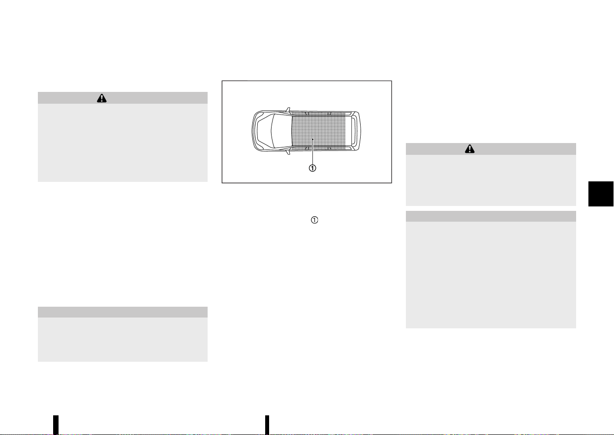
(249,1)
MEVT33A1-AA9BA26A-B49B-43B0-A908-8512620A8F65
PRECAUTIONS ON PUSH-BUTTON IGNI-
TION SWITCH OPERATION
MEVT33A1-FF362985-1347-4C4B-B581-FBC7F400D6E5
WARNING
Do not operate the push-button ignition
switch while driving the vehicle except in an
emergency. (The engine will stop when the
ignition switch is pushed 3 consecutive times
or the ignition switch is pushed and held for
more than 2 seconds.) If the engine stops while
the vehicle is being driven, this could lead to a
crash and serious injury.
Before operating the push-button ignition switch,
be sure to push the park button to shift to the P
(Park) position.
INTELLIGENT KEY SYSTEM
MEVT33A1-93950981-2EF8-4850-AF58-D196C60679FB
The Intelligent Key system can operate the ignition
switch without taking the key out from your
pocket or bag. The operating environment and/
or conditions may affect the Intelligent Key system
operation. Some indicators and warnings for
operation are displayed on the vehicle information
display. (See “Vehicle information display warnings
and indicators” (P.91).)
CAUTION
* Be sure to carry the Intelligent Key with
you when operating the vehicle.
* Never leave the Intelligent Key inside the
vehicle when you leave the vehicle.
OPERATING RANGE
MEVT33A1-92477EFA-07C9-4598-8D1A-D0B5C62E916C
MSSD0436
The Intelligent Key can only be used for starting
the engine when the Intelligent Key is within the
specified operating range
.
When the Intelligent Key battery is almost dis-
charged or strong radio waves are present near
the operating location, the Intelligent Key system’s
operating range becomes narrower and may not
function properly.
If the Intelligent Key is within the operating range,
it is possible for anyone, even someone who does
not carry the Intelligent Key, to push the ignition
switch to start the engine.
* The cargo room area is not included in the
operating range but the Intelligent Key may
function.
* If the Intelligent Key is placed on the instru-
ment panel, inside the glove box or door
pocket, the Intelligent Key may not function.
* If the Intelligent Key is placed near the door or
window outside the vehicle, the Intelligent Key
may function.
If the battery of the Intelligent Key is discharged,
see “Intelligent Key battery discharge” (P.246).
PUSH-BUTTON IGNITION SWITCH POSI-
TIONS
MEVT33A1-974D7B79-BED6-4F09-AB6E-A579BEDC09E3
WARNING
Never place the ignition switch in the “OFF”
position while driving. The steering wheel may
lock and cause the driver to lose control of the
vehicle, resulting in serious vehicle damage or
personal injury.
CAUTION
* Do not leave the vehicle for extended
periods of time when the ignition switch
is in the ON position and the engine is not
running. This can discharge the battery.
* Use electrical accessories with the engine
running to avoid discharging the vehicle
battery. If you must use accessories while
the engine is not running, do not use them
for extended periods of time and do not
use multiple electrical accessories at the
same time.
Starting and driving 245
PUSH-BUTTON IGNITION SWITCH
PUSH-BUTTON IGNITION SWITCH
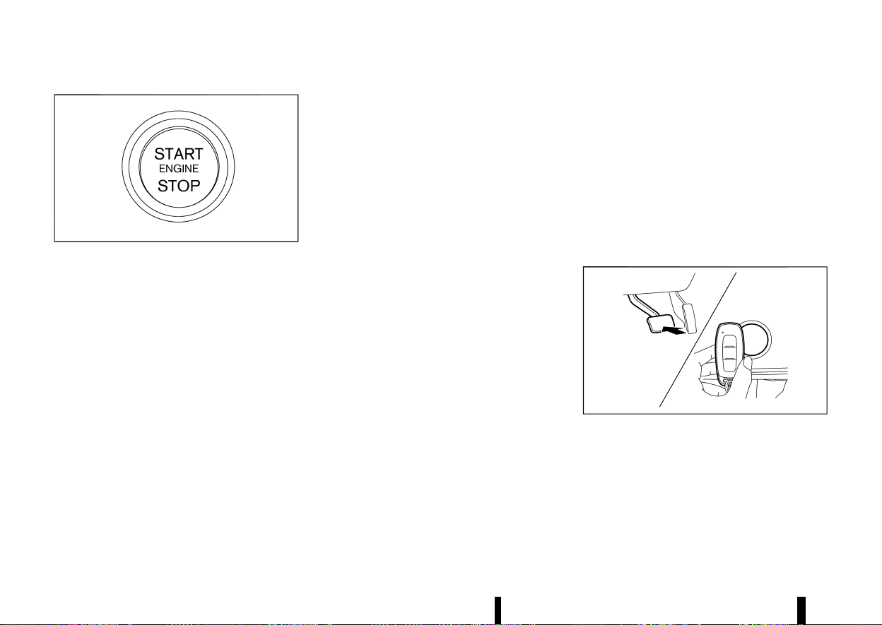
(250,1)
246 Starting and driving
MJVS1053X
When the ignition switch is pushed without
depressing the brake pedal, the ignition switch will
illuminate.
Push the ignition switch centre:
* once to change to ON.
* two times to change to “OFF”.
When the ignition switch cannot be placed in the
“OFF” position, proceed as follows:
1. Push the park button to shift to the P (Park)
position.
2. Push the ignition switch. The ignition switch
position will change to the ON position.
3. Push the ignition switch again to the “OFF”
position.
The shift position can be shifted from the P
(Park) position if the ignition switch is in the ON
position and the brake pedal is depressed.
ON (Normal operating position)
MEVT33A1-D9698FD3-051D-4467-807E-FFC14A493CA4
The ignition system and the electrical accessory
power activate at this position without the engine
turned on.
The ON position has a battery saver feature that
will place the ignition switch in the “OFF” position, if
the vehicle is not running, after some time under
the following conditions:
* ignition switch is in the ON position.
* the engine is stopped.
The battery saver feature will be cancelled if any of
the following occur:
* ignition switch is in the “OFF” position.
* the engine is running.
“OFF” position
MEVT33A1-A83721F2-C4C7-4D9A-826D-F29009E67A40
The engine is turned off in this position.
Auto ACC position
MEVT33A1-F5678EC4-E8AB-4C49-8E37-0CBBB1B55191
With the vehicle in the P (Park) position, the
Intelligent Key with you and the ignition placed
from ON to “OFF”, the radio can still be used for a
period of time, or until the driver’s door is opened.
After a period of time, functions such as radio,
navigation (where fitted), and Bluetooth Hands-
Free Phone System may be restarted by turning on
the audio system (see “Audio system (where fitted)”
(P.213) or the separate NissanConnect Owner’s
Manual), or by pushing the UNLOCK button on
the Intelligent Key for up to a total of 30 minutes.
EMERGENCY ENGINE SHUT OFF
MEVT33A1-CBB805D6-14E9-451C-B7A9-7F58A6DE7098
To shut off the engine in an emergency situation
while driving or when the Intelligent Key battery is
discharged, perform the following procedure:
* Rapidly push the push-button ignition switch 3
consecutive times in less than 1.5 seconds, or
* Push and hold the push-button ignition switch
for more than 2 seconds.
After engine shut-off, open the door to return to
the normal condition.
INTELLIGENT KEY BATTERY DISCHARGE
MEVT33A1-B0D1956A-5575-426F-A28A-6ED797C76123
MWAF1162X
If the battery of the Intelligent Key is discharged, or
environmental conditions interfere with the Intel-
ligent Key operation, start the engine according to
the following procedure:
1. Push the park button to shift to the P (Park)
position.
2. Firmly apply the footbrake.

(251,1)
3. Touch the ignition switch with the Intelligent
Key as illustrated. (A chime will sound.)
4. Push the ignition switch while depressing the
brake pedal within 10 seconds after the chime
sounds. The engine will start.
After step 3 is performed, when the ignition switch
is pushed without depressing the brake pedal, the
ignition switch position will change to ON.
NOTE:
* When the ignition switch is placed in the ON
position or the engine is started by the
above procedures, the [Key Battery Low]
warning appears (on the vehicle information
display) even if the Intelligent Key is inside
the vehicle. This is not a malfunction. To turn
off the warning, touch the ignition switch
with the Intelligent Key again.
* If the [Key Battery Low] warning appears,
replace the battery as soon as possible. (See
“Intelligent Key battery” (P.439).)
MEVT33A1-7408FE11-64BC-4759-BC8E-07366732C0C9
1. Apply the parking brake.
2. Confirm that the vehicle is in the P (Park)
position.
The Intelligent Key must be carried when
operating the ignition switch.
3. Push the ignition switch to the ON position.
Depress the brake pedal and push the ignition
switch to start the engine.
To start the engine immediately, push and
release the ignition switch while depressing
the brake pedal with the ignition switch in any
position.
.
If the engine is very hard to start in
extremely cold weather or when restarting,
depress the accelerator pedal a little (ap-
proximately 1/3 to the floor) and while
holding, crank the engine. Release the
accelerator pedal when the engine starts.
.
If the engine is very hard to start because it
is flooded, depress the accelerator pedal all
the way to the floor and hold it. Push the
ignition switch to the ON position to start
cranking the engine. After 5 or 6 seconds,
stop cranking by pushing the ignition
switch to “OFF”. After cranking the engine,
release the accelerator pedal. Crank the
engine with your foot off the accelerator
pedal by depressing the brake pedal and
pushing the push-button ignition switch to
start the engine. If the engine starts, but
fails to run, repeat the above procedure.
CAUTION
* As soon as the engine has started, release
the ignition switch immediately.
* Do not operate the starter for more than 15
seconds at a time. If the engine does not
start, push the ignition switch to the “OFF”
position and wait 10 seconds before crank-
ing the engine again. Otherwise, the star-
ter could be damaged.
* If it becomes necessary to start the engine
with a booster battery and jumper cables,
the instructions and cautions contained in
the “6. In case of emergency” section
should be carefully followed.
4. Warm-up
Allow the engine to idle for at least 30 seconds
after starting. Do not race the engine while
warming it up. Drive at moderate speed for a
short distance first, especially in cold weather.
In cold weather, keep the engine running for a
minimum of 2 - 3 minutes before shutting it
off. Starting and stopping the engine over a
short period of time may make the vehicle
more difficult to start.
When the engine is racing with no load and
cold, the engine speed is limited to about
3,000 rpm.
5. To stop the engine, push the park button to
shift to the P (Park) position, and push the
ignition switch to the “OFF” position.
Starting and driving 247
STARTING THE ENGINE
STARTING THE ENGINE
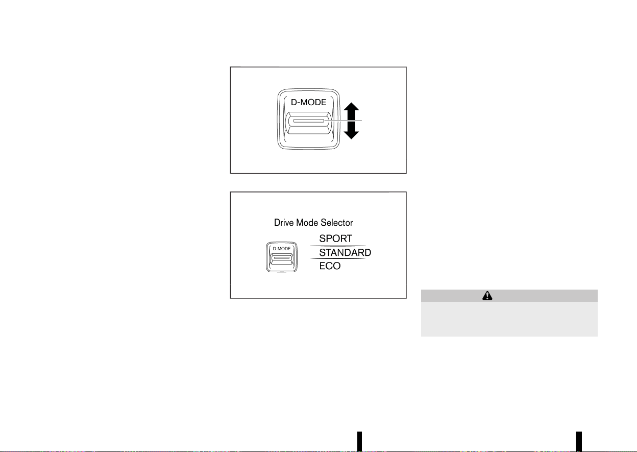
(252,1)
248 Starting and driving
NOTE:
Care should be taken to avoid situations that
can lead to potential battery discharge and
potential no-start conditions such as:
1. Installation or extended use of electronic
accessories that consume battery power
when the engine is not running (Phone
chargers, GPS, DVD players, etc.)
2. Vehicle is not driven regularly and/or only
driven short distances.
In these cases, the battery may need to be
charged to maintain battery health.
MEVT33A1-031CD07C-8FE5-4C2E-8674-E6F80C73C6D7
MWAF0514X
Drive Mode Selector
MWAF0540X
Vehicle information display
Multiple driving modes can be selected by using
the Drive Mode Selector ([SPORT], [STANDARD] and
[ECO]).
To change the mode, push the Drive Mode Selector
up or down.
NOTE:
When the Drive Mode Selector selects a mode,
the mode may not switch immediately. This is
not a malfunction.
The current mode is displayed in the vehicle
information display. The mode list will appear in
the vehicle information display and you can select
the mode.
NOTE:
The mode list will be turned off in approximately
5 seconds after the mode is selected.
You can also clear the message by pushing the
scroll dial on the steering wheel.
If the driving mode cannot be switched using the
Drive Mode Selector when the ignition switch is in
the ON position, have the system checked. It is
recommended you visit a NISSAN dealer or quali-
fied workshop for this service.
The [STANDARD] mode will be selected first each
time the ignition switch is placed in the "ON"
position.
WARNING
Do not stare at the Drive Mode Selector or the
display while driving so that full attention may
be given to vehicle operation.
DRIVE MODE SELECTOR
DRIVE MODE SELECTOR
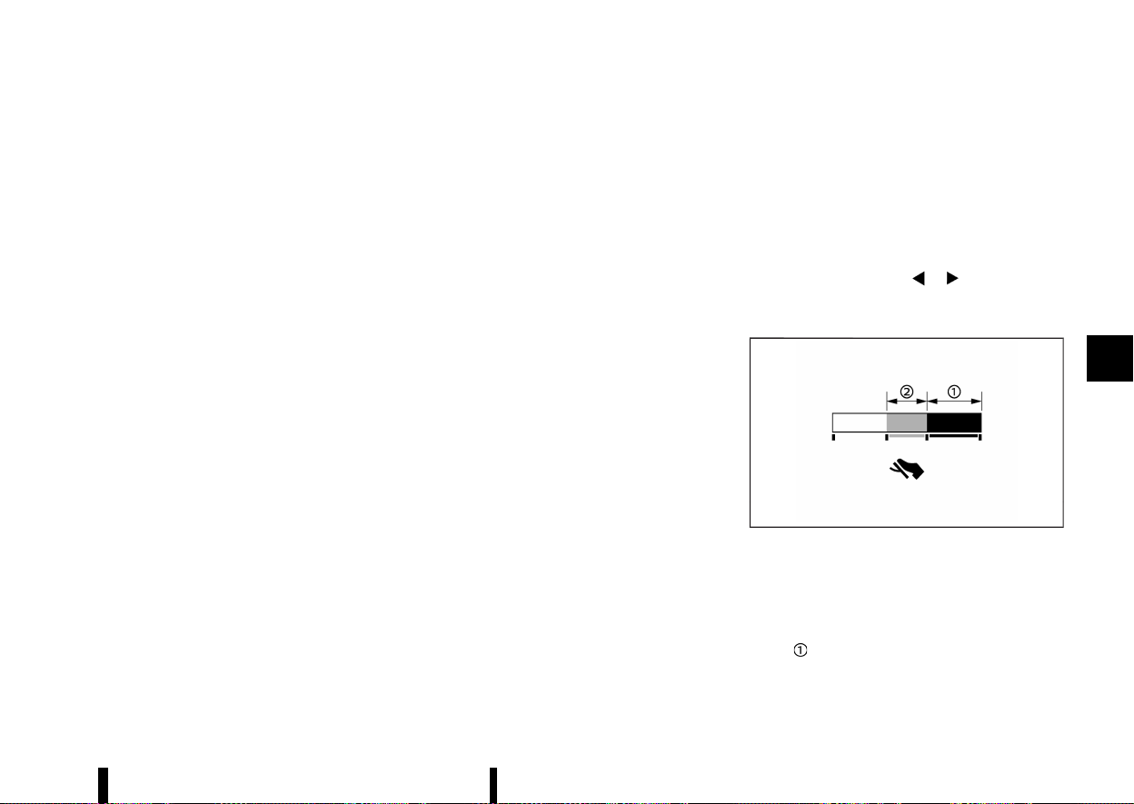
(253,1)
SPORT MODE
MEVT33A1-08F7C655-3046-4E78-B8DE-D752FD49E6D9
* Adjusts the engine and transmission points for
a higher response.
* The setting of the steering system is adjusted
to moderately increase steering wheel effort
for a sporty feel.
NOTE:
In the SPORT mode, fuel economy may be
reduced.
STANDARD MODE
MEVT33A1-35F0998C-B51C-4F54-8419-196C02025ABF
This is the standard mode that is most suitable for
normal driving.
ECO MODE
MEVT33A1-AEB3DD59-37A3-4144-905F-B5FD9A5F1CA7
Assists the driver’s ECO-driving. The engine and
transmission points are adjusted for improved fuel
economy, providing such driving features as
smooth starting or constant cruising.
NOTE:
* Selecting the [ECO] mode will not necessarily
improve fuel economy as many driving
factors influence its effectiveness.
* It is recommended to select other than [ECO]
mode when acceleration is required such as
when:
— driving with a heavy load of passengers or
cargo in the vehicle
— driving on a steep uphill slope
Operation
MEVT33A1-AF625E50-3A5E-4876-9B7A-C70C2EF7EBC9
Select the [ECO] mode using the Drive Mode
Selector. The ECO indicator illuminates.
ECO Drive Mode
MEVT33A1-F6C8E0D5-F9C2-4C04-81F8-3D250E769D26
When the ECO mode of the “ECO Cruise Control”,
“Stop/Start” and/or “ECO Climate Control” in addi-
tion to the conventional power train control is ON,
more actual fuel economy is achieved by placing
priority on fuel efficiency. It can be set when the
ECO mode is selected. To activate or deactivate
this function, see “[ECO Settings]” (P.85).
* [ECO Cruise Control] (where fitted)
When the setting is ON, the fuel efficiency while
cruising will be improved by lowering the
acceleration target from normal (setting OFF)
mode.
* [Stop/Start]
When the setting is ON, the Stop/Start time will
be extended more than normal mode when
using the air conditioner.
* [ECO Climate Control]
When the setting is ON, the fuel efficiency will
be improved by reducing the performance of
the air conditioning system.
NOTE:
When the vehicle speed is reduced (for example,
when the vehicle is driven on an uphill road from
a flat road), it will take more time to return to the
previously set speed than normal mode.
[Tyre ECO advice] (where fitted)
MEVT33A1-18255C65-641D-40D7-8C9F-AF5C0C342E7C
The [Tyre ECO advice] is a function to show an ECO
advice message in the vehicle information display
when low tyre pressure is detected. To activate or
deactivate this function, see “[ECO Settings]” (P.85).
When the setting is ON, the ECO Drive Report
display shows [ECO Advice Adjust Tyre Pressures].
You can switch the display to the Tyre Pressures
display by pushing the
button on the
steering wheel.
ECO Pedal Guide function
MEVT33A1-F686183F-9E35-408A-9B58-362E396FEA36
MWAF0126X
The ECO Pedal Guide display can be selected in the
vehicle information display in the ECO mode. (See
“5. ECO Pedal Guide” (P.103).) Use the ECO Pedal
Guide function for improving fuel economy.
When the ECO Pedal Guide bar is in the green
range
, it indicates that the vehicle is being
driven within range of the super economy drive.
When the ECO Pedal Guide bar is in the light green
Starting and driving 249

(254,1)
250 Starting and driving
range , it indicates that the vehicle is being
driven within range of the economy drive.
If the ECO Pedal Guide bar is out of the green
range (
and ), it indicates that the accelerator
pedal is depressed over the range of economy
drive.
The ECO Pedal Guide bar is not displayed when:
* The vehicle speed is less than approximately 4
km/h (2 MPH).
* The shift lever is in the P (Park), N (Neutral) or R
(Reverse) position.
MEVT33A1-0099E665-725B-489E-B596-F5A3F4CD54DB
CONTINUOUSLY VARIABLE TRANSMIS-
SION (CVT)
MEVT33A1-C699DF0B-987D-4AD2-879E-72829424A200
The CVT in your vehicle is electronically controlled
to produce maximum power and smooth opera-
tion.
The recommended operating procedures for this
transmission are shown on the following pages.
Follow these procedures for maximum vehicle
performance and driving enjoyment.
Engine power may be automatically reduced to
protect the CVT if the engine speed increases
quickly when driving on slippery roads or while
being tested on some dynamometers.
WARNING
* Do not depress the accelerator pedal while
shifting from P (Park) or N (Neutral) to R
(Reverse), D (Drive), or “M” (Manual shift
mode). Always depress the brake pedal
until shifting is completed. Failure to do so
could cause you to lose control and have
an accident.
* Cold engine idle speed is high, so use
caution when shifting into a forward or
reverse gear before the engine has
warmed up.
* Do not downshift abruptly on slippery
roads. This may cause a loss of control.
* Never shift to either the P (Park) or R
(Reverse) position while the vehicle is
moving forward and P (Park) or D (Drive)
position while the vehicle is reversing. This
could cause an accident or damage the
transmission.
* Except in an emergency, do not shift to the
N (Neutral) position while driving. Coasting
with the transmission in the N (Neutral)
position may cause serious damage to the
transmission.
CAUTION
* To avoid possible damage to your vehicle,
when stopping the vehicle on an uphill
grade, do not hold the vehicle by depres-
sing the accelerator pedal. The footbrake
should be used for this purpose.
* Do not hang items on the shift lever. This
may cause an accident due to a sudden
start.
Starting the vehicle
MEVT33A1-5D273D53-F49E-430A-9675-CA17371F1DFA
1. After starting the engine, fully depress the
footbrake pedal before attempting to place
the shift position out of the P (Park) position.
This CVT is designed so that the footbrake
pedal must be depressed before shifting
from P (Park) to any driving position while
the ignition switch is in the ON position. The
shift position cannot be placed out of the P
(Park) position and into any of the other
positions if the ignition switch is placed in
the “OFF” position.
2. Keep the footbrake pedal depressed and move
the shift lever into a driving position.
DRIVING THE VEHICLE
DRIVING THE VEHICLE
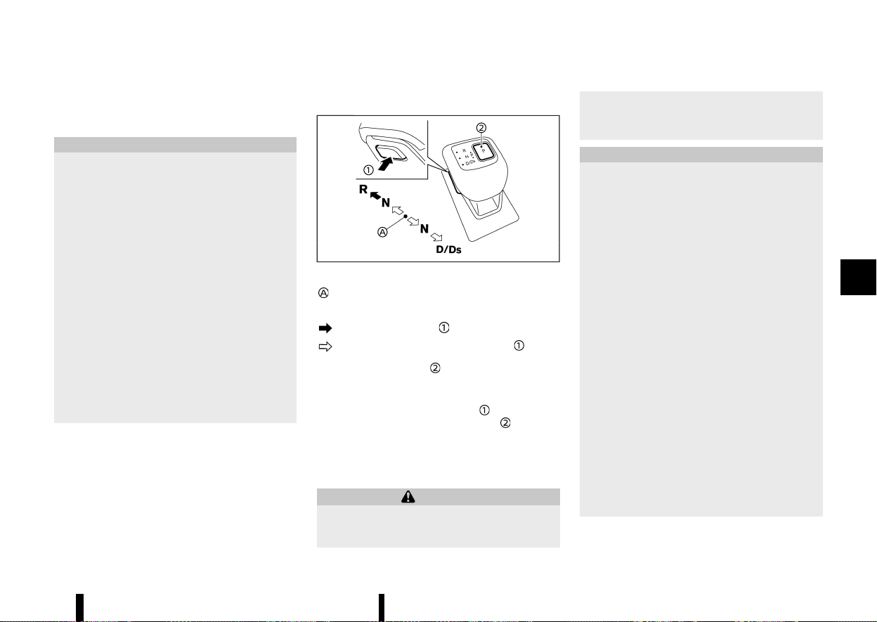
(255,1)
3. Release the parking brake, the footbrake
pedal, and then gradually start the vehicle in
motion.
CAUTION
* DEPRESS THE FOOTBRAKE PEDAL - Shifting
the shift lever to the D (Drive), “Ds” (Drive
Sport), R (Reverse) or the manual shift
mode without depressing the footbrake
pedal causes the vehicle to move slowly
when the engine is running. Make sure the
footbrake pedal is depressed fully and the
vehicle is stopped before shifting the shift
lever.
* MAKE SURE OF THE SHIFT LEVER POSITION
- Make sure the shift position is in the
desired position on the vehicle information
display. D (Drive), “Ds” (Drive Sport) and the
manual shift mode are used to move
forward and R (Reverse) to reverse.
* WARM UP THE ENGINE - Due to the higher
idle speeds when the engine is cold, extra
caution must be exercised when shifting
the shift lever into the driving position
immediately after starting the engine.
Shifting
MEVT33A1-8E33D228-CFD5-4E80-8A5F-A2EC598FE23A
MWAF0837X
Left-Hand Drive (LHD) model
Home position (central position)
To move the shift lever,
: Push the button to shift.
: Shift without pushing the button .
Push the park button to shift to the P (Park)
position.
After starting the engine, fully depress the brake
pedal, push the shift lever button
and move the
shift lever from the P (Park) position
to any of
the desired shift positions.
Confirm that the vehicle is in the desired shift
position by checking the shift indicator located on
the shift lever or on the vehicle information display.
WARNING
Apply the electronic parking brake if the shift
lever is in any position while the engine is not
running. Failure to do so could cause the
vehicle to move unexpectedly or roll away and
result in serious personal injury or property
damage.
CAUTION
* Use the P (Park), R (Reverse) or D (Drive)
position only when the vehicle is comple-
tely stopped.
* When switching to the desired shift posi-
tion by operating the shift lever, check that
the shift lever returns to the central posi-
tion by releasing your hand from the lever.
Holding the shift lever in a mid-way posi-
tion may also damage the shift control
system.
* Do not operate the shift lever while the
accelerator pedal is depressed. This may
cause a sudden start which could result in
an accident.
* The following operations are not allowed
because excessive force would be applied
to the transmission and this may result in
damage to the vehicle:
— Moving the shift lever to the R (Re-
verse) position when driving forward
— Moving the shift lever to the D (Drive)
position when reversing
If these operations are attempted, a chime
sounds and the vehicle shifts to the N
(Neutral) position.
Starting and driving 251

(256,1)
252 Starting and driving
P (Park):
CAUTION
* To prevent transmission damage, use the
P (Park) position only when the vehicle is
completely stopped.
* Do not slide the shift lever while pushing
the park button. This may damage the
shift control system.
Use this position when the vehicle is parked or
starting the engine. Always make sure that the
vehicle is completely stopped before pushing the
park button to engage the P (Park) position. For
maximum safety, the brake pedal must be de-
pressed before engaging the P (Park) position. Use
this position together with the electronic parking
brake. When parking on a hill, first depress the
brake pedal, apply the electronic parking brake
and then engage the P (Park) position. The parking
lock should not be used as a brake when parking.
In order to secure the vehicle, always apply the
electronic parking brake in addition to the parking
lock.
In the event of a malfunction of the vehicle’s
electronics, the transmission may lock in the P
(Park) position. Have the vehicle’s electronics
checked immediately. It is recommended that
you visit a NISSAN dealer or qualified workshop
for this service.
The P (Park) position is automatically engaged if:
* You switch off the ignition switch
* You unfasten the driver’s seat belt and open
the driver side door when the vehicle is
stationary or driving at very low speed and
the transmission is in the D (Drive) position, the
R (Reverse) position or the N position unless
the Neutral hold mode is engaged.
CAUTION
To avoid CVT malfunction, it is recommended
that you manually place the shift position in
the P (Park) position under the above condi-
tions.
R (Reverse):
CAUTION
To prevent transmission damage, use the R
(Reverse) position only when the vehicle is
completely stopped.
Use the R (Reverse) position to reverse. Make sure
the vehicle is completely stopped before selecting
the R (Reverse) position. The brake pedal must be
depressed and the shift lever button pushed to
move the shift lever from the home position to R
(Reverse). If the vehicle is placed in the R
(Reverse) position while the vehicle is moving
forward, the chime will sound and the vehicle
will switch into the N (Neutral) position.
N (Neutral):
Neither the forward nor reverse gear is engaged.
The engine can be started in this position. You may
shift to the N (Neutral) position and restart a stalled
engine while the vehicle is moving.
You can select this position by holding the shift
lever at this position for 0.5 seconds.
D (Drive):
Use this position for all normal forward driving. The
CVT changes gears automatically. All forward
gears are available. If the vehicle is placed in the
D (Drive) position while the vehicle is reversing,
the chime will sound and the vehicle will switch
into the N (Neutral) position.
Ds (Drive Sport):
When the shift lever is moved to the D (Drive)
position again with the vehicle in the D (Drive)
position while driving, the transmission enters the
Ds (Drive Sport) mode. Moving the shift lever to the
“Ds” (Drive Sport) mode allows you to enjoy “sporty”
driving shift operation on a winding road and feel
smooth acceleration or deceleration on a hilly road
by moving in a lower gear automatically. When
cancelling the Ds (Drive Sport) mode, move the
shift lever to the D (Drive) position again. The
transmission returns to the D (Drive) position.
NOTE:
* The Ds (Drive Sport) mode is not just for
sporty driving, it can also be used when
overtaking, for example.
* When driving conditions change, turn the Ds
(Drive Sport) mode off.
* The Ds (Drive Sport) mode reduces fuel
economy.
Neutral hold mode function
MEVT33A1-AD4A18B6-6471-4D3A-A323-DF242D375AD7
This function enables you to turn off the engine
with the vehicle in the N (Neutral) position. While
this function is activated, the vehicle can be moved
by pushing with hand even if the ignition switch is
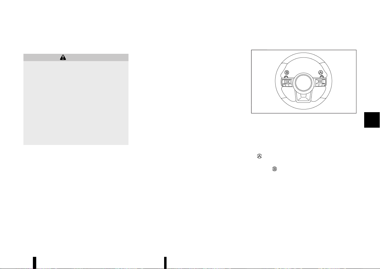
(257,1)
in the “OFF” position. When using this function,
release the electronic parking brake.
WARNING
* Use this function on a level surface only.
Failure to do so may cause the vehicle to
move accidentally and could result in a
collision or serious personal injury.
* When the ignition switch is placed in the
ON position after activating this function,
depress the brake pedal to stop the vehicle
because the shift lever is in the N (Neutral)
position.
* If this function is not activated regardless
of proper operation, transmission may
malfunction. It is recommended that you
visit a NISSAN dealer or qualified workshop
for this service.
To activate the Neutral hold mode, perform the
following operations.
1. Push the ignition switch to start the engine.
2. Release the electronic parking brake and
Automatic brake hold function.
3. Depress and hold the brake pedal. Slide the
shift lever to move the transmission out of the
"P" (Park) position.
4. Push the park button.
5. Slide the shift lever to the N (Neutral) position,
and hold it for approximately 0.5 seconds until
N appears in the vehicle information display
and then return the lever to the central
position.
6. Slide the shift lever to the N (Neutral) position
again, and hold it for approximately 0.5
seconds, until a message “Park Gear & Park
Brake not Applied” appears in the vehicle
information display. (See “62. Neutral Hold
Mode activated indicator (where fitted)”
(P.100).)
7. Place the ignition switch in the “OFF” position.
The engine will turn off with holding the N
(Neutral) position.
To exit the Neutral hold mode, place the vehicle in
other than N (Neutral) position.
NOTE:
* It is necessary to perform the steps 4
through 6 within approximately 5 seconds
and steps 5 and 6 within approximately 0.5
seconds to prevent incorrect operation.
* When the ignition switch is placed in the
“OFF” position while the shift lever is in the N
(Neutral) position, a message will appear in
the vehicle information display. (See “61.
Neutral Hold Mode guidance indicator
(where fitted)” (P.100).)
* If the Neutral hold mode is unavailable, a
message will appear in the vehicle informa-
tion display. (See “63. [Neutral Hold Mode
was not activated] indicator (where fitted)”
(P.100).) To activate the Neutral hold mode,
wait for a while without shifting operation
and then perform the operations again.
Manual shift mode
MEVT33A1-D712A263-68AD-455F-8166-C902EBCAB071
MWAF0417X
Paddle shifter
When using the paddle shifters while in the “Ds”
(Drive Sport) mode, the transmission enters the
manual shift mode. Shift range can be selected
manually using the paddle shifters.
When shifting up, pull the right-side paddle shifter
(+)
. The transmission shifts to the higher range.
When shifting down, pull the left-side paddle
shifter (−)
. The transmission shifts to the lower
range.
When cancelling the manual shift mode, move the
shift lever to the D (Drive) position again. The
transmission returns to the D (Drive) position. If
you want to return to the “Ds” (Drive sport) mode
manually, pull and hold the paddle shifter for about
1.5 seconds.
When you pull the paddle shifter while in the D
(Drive) position, the transmission will shift to the
upper or lower range temporarily. The transmis-
sion will automatically return to the D (Drive)
Starting and driving 253

(258,1)
254 Starting and driving
position after a short period of time. If you want to
return to the D (Drive) position manually, pull and
hold the paddle shifter for about 1.5 seconds.
In the manual shift mode, the shift range is
displayed in the vehicle information display.
Shift ranges up or down one by one as follows:
1
M
?
/
2
M
?
/
3
M
?
/
4
M
?
/
5
M
?
/
6
M
?
/
7
M
?
/
8
M
8
M
(8th):
Use this position for all normal forward driving at
highway speeds.
7
M
(7th), 6
M
(6th) and 5
M
(5th):
Use these positions when driving up long slopes, or
for engine braking when driving down long slopes.
4
M
(4th), 3
M
(3rd) and 2
M
(2nd):
Use these positions for hill climbing or engine
braking on downhill grades.
1
M
(1st):
Use this position when climbing steep hills slowly
or driving slowly through deep snow, or for
maximum engine braking on steep downhill
grades.
* Remember not to drive at high speeds for
extended periods of time in lower than 8th
gear. This reduces fuel economy.
* Pulling the same paddle shifter twice will shift
the ranges in succession. However, if this
motion is rapidly done, the second shifting
may not be completed properly.
* In the manual shift mode, the transmission
may not shift to the selected gear. This helps
maintain driving performance and reduces
the chance of vehicle damage or loss of
control.
* When this situation occurs, the Continuously
Variable Transmission (CVT) position indica-
tor will blink and the chime will sound.
* In the manual shift mode, the transmission
may shift up automatically to a higher range
than selected if the engine speed is too high.
When the vehicle speed decreases, the
transmission automatically shifts down and
shifts to 1st gear before the vehicle comes to
a stop.
* CVT operation is limited to automatic drive
mode when CVT fluid temperature is extre-
mely low even if manual shift mode is selected.
This is not a malfunction. When CVT fluid
warms up, manual shift mode can be selected.
* When the CVT fluid temperature is high, the
shift range may upshift in lower rpm than
usual. This is not a malfunction.
Gear Shift Indicator (where fitted)
MEVT33A1-B7A846C5-FB6E-4F69-B488-200CFE8552B4
MWAF1238X
Gear Shift Indicator appears in the transmission
position indicator when the driver should shift into
a higher gear as indicated by the up arrow.
The use of Gear Shift Indicator will help to reduce
fuel consumption.
When the up arrow appears, upshifting is recom-
mended.
Gear shift recommendation may not be available
depending on the conditions.
CAUTION
Gear Shift Indicator helps to reduce fuel con-
sumption. It does not recommend the appro-
priate gear shift for all driving situations. In a
certain situations, only the driver can select the
correct gear (for example, when overtaking,
driving up a steep gradient or towing a trailer).

(259,1)
Accelerator downshift - in D (Drive) POSITION -
MEVT33A1-BF3E06A6-2637-42C1-966D-5E30031CA744
For passing or climbing hills, depress the accel-
erator pedal to the floor. This shifts the transmis-
sion down into a lower gear, depending on the
vehicle speed.
High fluid temperature protection mode
MEVT33A1-CE869FBC-89CE-4D62-AEC8-660F5235AF18
This transmission has a high fluid temperature
protection mode. If the fluid temperature becomes
too high, (for example, when climbing steep grades
in high temperatures with heavy loads), engine
power and, under some conditions, vehicle speed
will be decreased automatically to reduce the
chance of transmission damage. Vehicle speed
can be controlled with the accelerator pedal, but
the engine and vehicle speed may be limited.
Fail-safe
MEVT33A1-EA910347-92E1-44D4-9256-120D487E42CA
When the fail-safe operation occurs, the Continu-
ously Variable Transmission will not be shifted into
the selected driving position.
If the vehicle is driven under extreme conditions,
such as excessive wheel spinning and subse-
quent hard braking, the fail-safe system may be
activated. The Malfunction Indicator Light (MIL)
may come on to indicate the fail-safe mode is
activated. For additional information, refer to
“Malfunction Indicator Light (MIL)” (P.79). This will
occur even if all electrical circuits are functioning
properly. In this case, place the ignition switch in
the “OFF” position and wait for 10 seconds. Then
place the ignition switch back in the ON position.
The vehicle should return to its normal operat-
ing condition. (The MIL may be illuminated even
when the vehicle has returned to its normal
operating condition.) If it does not return to its
normal operating condition, have the transmis-
sion checked and repaired, if necessary, by a
NISSAN dealer or qualified workshop.
WARNING
When the high fluid temperature protection
mode or fail-safe operation occurs, vehicle
speed may be gradually reduced. The reduced
speed may be lower than other traffic, which
could increase the chance of a collision. Be
especially careful when driving. If necessary,
pull to the side of the road at a safe place and
allow the transmission to return to normal
operation, or have it repaired if necessary.
MEVT33A1-F000F42D-C773-4581-BC6F-21A01803CB3F
The Stop/Start System is designed to prevent
unnecessary fuel consumption, exhaust emissions,
and noise during a journey.
There are two functions for the Stop/Start System,
the regular Stop/Start System and the Stop/Start
System before the vehicle halt.
* When you stop the vehicle with the brake
pedal depressed the engine is turned off
automatically. (Stop/Start System)
* When the vehicle slows to approximately 18
km/h (11 MPH) with the brake pedal depressed,
the engine is turned off automatically. (Stop/
Start System before the vehicle halt)
* When you release the brake pedal, the engine
is automatically turned on.
CAUTION
* The engine may restart automatically if
required by the Stop/Start System.
* Place the ignition switch in the “OFF”
position before opening the bonnet or
performing any maintenance. Failure to
do so may result in serious injuries due to
automatic engine restart.
* Always place the ignition switch in the
“OFF” position before leaving your vehicle,
as the system may have turned the engine
off, but the ignition will still be on and
automatic restart may occur.
Failure to do this may result in a flat
battery.
Starting and driving 255
STOP/START SYSTEM
STOP/START SYSTEM

(260,1)
256 Starting and driving
NOTE:
For model with Stop/Start System, use the
special battery that is enhanced in regard to
the charge-discharge capacity and life perfor-
mance. Avoid using a non-special battery for the
Stop/Start System, as this may cause early
deterioration of the battery or a malfunction of
the Stop/Start System. For the battery, it is
recommended to use Genuine NISSAN parts.
For more information, contact a NISSAN dealer
or qualified workshop.
NOTE:
The Stop/Start System or the Stop/Start System
before the vehicle halt will not activate under the
following conditions:
* when the engine is kept idling without any
driving after the engine is turned on.
* when the engine coolant temperature is low.
* when the battery capacity is low.
* when the battery temperature is low.
* when the vacuum in the brake servo de-
creases.
* when the engine bonnet is opened with the
engine running.
* when the engine is turned on with the
engine bonnet open.
* when the driver’s seat belt is not fastened.
* when the driver’s door is open.
* when the Stop/Start System indicator
blinks.
* when the fan speed control is in any position
other than “OFF” while the air flow control is
in the front defogger position.
* when the front defogger switch is on.
* when the temperature inside the vehicle is
too hot. (When the air conditioner is off, the
Stop/Start System will operate.)
* when the temperature inside the vehicle is
too low. (When the fan speed control is
“OFF”, the Stop/Start System will operate.)
* when the Stop/Start OFF switch is turned
on.
* when altitude is high.
* when the power consumption is large.
* when the accelerator pedal is depressed.
* when the shift lever is in the R (Reverse)
position.
* when the brake pedal is not firmly de-
pressed.
NOTE:
The Stop/Start System or the Stop/Start System
before the vehicle halt may not activate when
the Intelligent Key is not in the vehicle and
opening/closing any door.
NOTE:
The Stop/Start System will not activate under
the following conditions:
* when the vehicle is moved.
* when stopping the vehicle on steep sloping
roads.
NOTE:
The Stop/Start System before the vehicle halt
will not activate under the following conditions:
* when the vehicle speed is above 18 km/h (11
MPH).
* when the shift lever is placed in other than D
(Drive) position.
* when driving on other than flat roads.
* when the ProPILOT Assist system (where
fitted) is activated.
NOTE:
The engine will not restart even if the brake
pedal is released while the Stop/Start System is
activated under the following condition (the
engine may restart under other conditions):
* when the shift lever is in the P (Park)
position.
* when the shift lever is in the N (Neutral)
position and the parking brake is applied.
* when the engine bonnet is opened.
* when Automatic brake hold is activated.
* when the ProPILOT Assist system (where
fitted) is activated.
NOTE:
It may take some time until the Stop/Start
System or the Stop/Start System before the
vehicle halt activates under the following con-
ditions:
* when the battery is discharged.
* when the outside temperature is low or high.
* after the 12-volt battery (main) is replaced or
after the terminal of 12-volt battery (main) is
disconnected for extended period of time.

(261,1)
NOTE:
While the Stop/Start or the Stop/Start System
before the vehicle halt activates, the engine
restarts running automatically under at least
one of the following conditions:
* the driver’s seat belt is unfastened, or the
driver’s door is open.
* the battery voltage becomes low (due to
electrical load from other vehicle systems
like headlights, heaters, etc., or auxiliary
devices connected to the 12–volt socket
inside the vehicle).
* the vehicle speed is above about 2 km/h (1
MPH).
* when the front defogger is operated.
* when the temperature inside the vehicle is
too hot. (When the air conditioner is off, the
Stop/Start System will operate.)
* when the temperature inside the vehicle is
too low. (When the fan speed control is
“OFF”, the Stop/Start System will operate.)
* when the front defogger is turned on.
* when more than 3 minutes have elapsed
since engine was stopped.
* when the accelerator pedal is depressed.
* when the battery capacity is low.
* when the power consumption is high.
* when the Stop/Start OFF switch is turned
on.
* when the ProPILOT Assist system is set to
operate (the engine may not start depend-
ing on the amount of brake pedal depres-
sion) (where fitted).
* when the ProPILOT Assist system is acti-
vated and the driver operates the system to
start the vehicle (where fitted).
* when the ProPILOT Assist system is acti-
vated and the vehicle ahead is started
(where fitted).
* when the negative pressure of the brake
system is not sufficiently applied by depres-
sing the brake pedal several times.
NOTE:
While the Stop/Start or the Stop/Start System
before the vehicle halt activate, the engine may
restart when the Intelligent Key is not in the
vehicle and open/close any door.
NOTE:
The engine will restart while the Stop/Start
System activates under the following conditions:
* when the vehicle starts moving on the slope
as the braking force is released.
* when the shift lever is placed in the R
(Reverse) position.
* when the brake pedal is released with the
shift lever in “Ds” (Drive Sport), D (Drive) or N
(Neutral) position.
* when the shift lever is placed in “Ds” (Drive
Sport) or D (Drive) position from N (Neutral)
or P (Park) position.
* the brake pedal is released when the shift
lever is in the D (Drive) or N (Neutral) position
and the parking brake is not applied.
* the parking brake is released when the shift
lever is in the N (Neutral) position and the
brake pedal is not depressed.
* when the paddle shifter is operated with the
shift lever in D (Drive) or “Ds” (Drive Sport)
position.
NOTE:
The following condition will prevent the Stop/
Start System from automatically restarting the
engine. Starting the engine with the ignition
switch operation is then necessary:
* the bonnet is open.
NOTE:
The engine will restart while the Stop/Start
System before the vehicle halt activates under
the following conditions:
* when the vehicle speed becomes approxi-
mately 18 km/h (11 MPH).
* when the shift lever is placed in other than D
(Drive) position.
* when the bonnet opening is detected.
* when the paddle shifter is operated with the
shift lever in D (Drive) position.
NOTE:
If the Intelligent Emergency Braking with Pedes-
trian Detection system activates while the Stop/
Start System before the vehicle halt is activating,
the engine will not restart while travelling. The
engine will restart after the vehicle is stopped.
NOTE:
when the steering wheel is operated while the
Stop/Start system activates, the steering wheel
operation may become heavy. But this is not a
malfunction.
Starting and driving 257
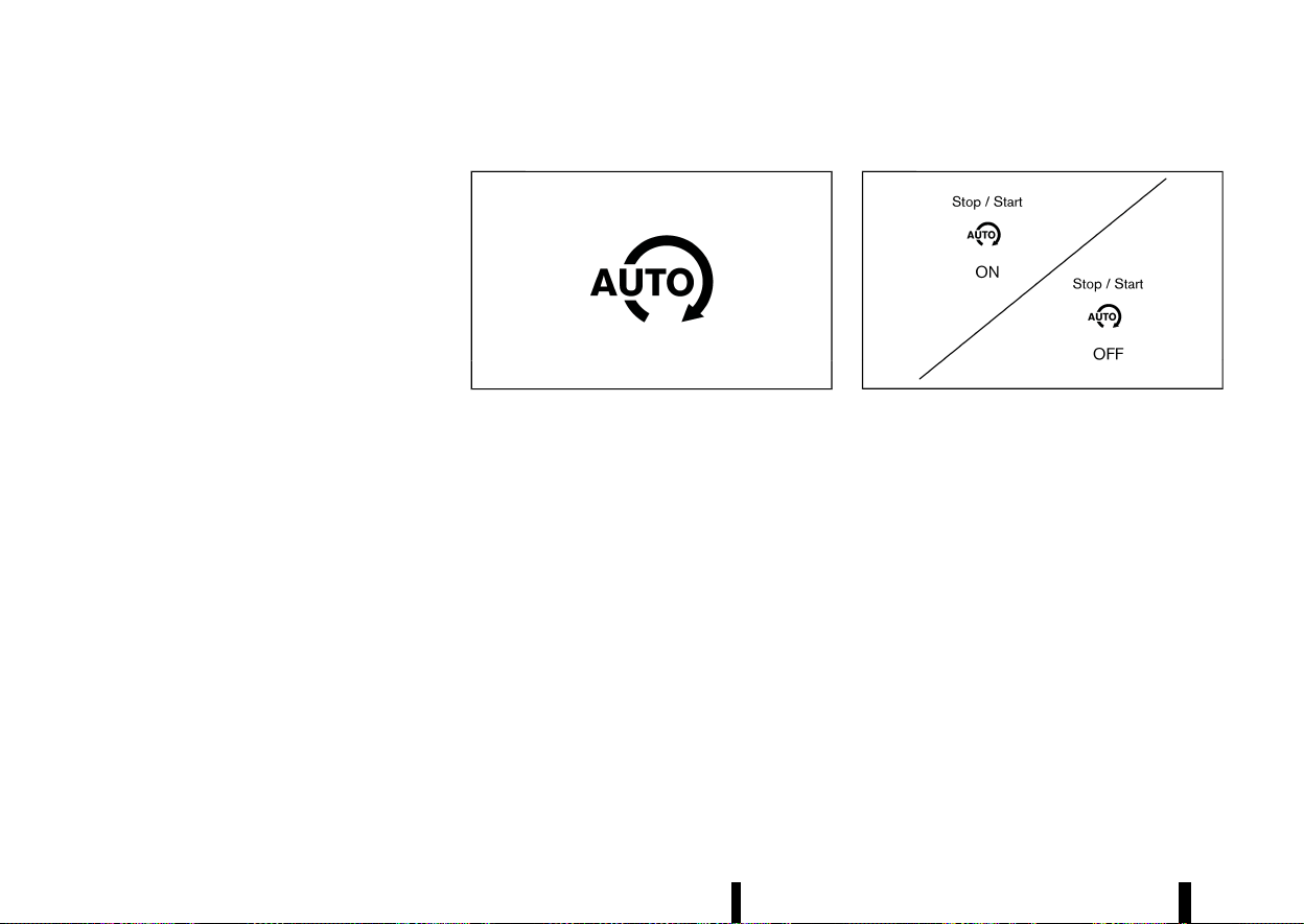
(262,1)
258 Starting and driving
Use this system while waiting at stoplight, etc.
When the vehicle is stopped for long periods of
time, turn off the engine.
When the engine is stopped by the Stop/Start
System, heating, cooling and dehumidifying func-
tions will be deactivated. To avoid the air con-
ditioning functions from being deactivated, turn
off the Stop/Start mode by pressing the Stop/
Start OFF switch.
RETROGRADE MOVEMENT CONTROL
FUNCTION
MEVT33A1-88AEEF99-7F6E-4513-9746-CFB664D6B47F
* The system is designed to reduce the retro-
grade movement that occurs while the driver’s
foot changes from depressing the brake pedal
to the accelerator pedal when moving the
vehicle while the Stop/Start System is active
on a hilly road.
* Since this equipment utilizes the brake control
by Vehicle Dynamic Control (VDC)/Electronic
Stability Programme (ESP) system, the system
does not activate when the slip indicator light
in the meter panel illuminates.
STOP/START SYSTEM DISPLAY
MEVT33A1-147C5E45-7C84-47AD-89C8-DC90D94B9B9D
The status of the Stop/Start System can be
checked in the vehicle information display.
Stop/Start System indicator
MEVT33A1-6F2A0245-982F-48BA-872B-DFEE1D2B383A
MWAF1243X
This indicator is displayed when the Stop/Start
System is activated.
The indicator blinks when the Stop/Start System is
malfunctioning.
NOTE:
When the indicator blinks, have the system
checked, and if necessary repaired, by a NISSAN
dealer or qualified workshop promptly.
Stop/Start System ON or OFF
MEVT33A1-6075F9B4-98AF-497C-964F-A744762092D7
MJVS0342X
Example
If the Stop/Start System is activated or deacti-
vated using the Stop/Start OFF switch, the mes-
sage is shown.
If the Stop/Start System is deactivated using the
Stop/Start OFF switch, the Stop/Start OFF icon
also appears in the vehicle information display
(where fitted).
CO
2
saved and engine stop time
MEVT33A1-21503FD9-CEB0-4145-B7B0-58003082734B
There are two CO2 counters, one lifetime and one
that can be reset.
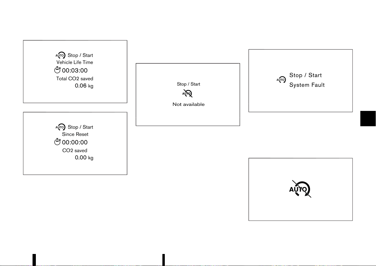
(263,1)
MWAF1163X
MWAF1252X
The CO
2
saved and engine stop time mode shows:
* The CO
2
saved shows the estimated quantity
of CO
2
exhaust emissions that were prevented
by the Stop/Start System every time the
engine is automatically stopped or since the
last reset, or in vehicle’s life time.
* The engine stop time shows the time that the
engine has been stopped by the Stop/Start
System since the last reset, or in vehicle’s life
time.
Auto start deactivation
MEVT33A1-5664D59B-FCAA-408B-AF7F-365FC5B34C9B
MJVS0344X
Example
If the engine stops when the Stop/Start System is
activated, and will not start automatically, the
message is shown.
System fault
MEVT33A1-DA6DAB5D-719C-46CE-A08D-A7E71FF53DF7
MWAF1168X
Example
This message is displayed when the Stop/Start
System is malfunctioning.
Have the system checked by a NISSAN dealer or
qualified workshop.
Stop/Start inhibition
MEVT33A1-E9FD3B9E-36D5-433D-9953-BF5F7F2E6669
MWAF0229X
This indicator is displayed when the vehicle is
Starting and driving 259
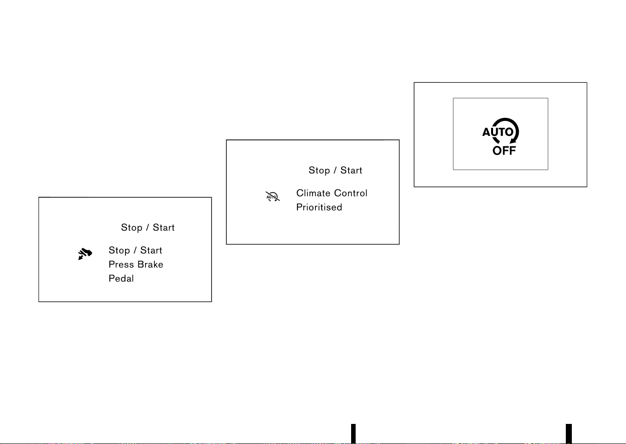
(264,1)
260 Starting and driving
stopped if the engine is prevented from automa-
tically stopping by the Stop/Start System under
the inhibition conditions. See “Stop/Start System”
(P.255).
This indicator is also displayed under the following
conditions:
* When the engine bonnet is opened while the
engine is kept idling.
* When the Stop/Start system is not activated
when the vehicle stops.
Stop/Start guidance display (further
depressing the brake pedal)
MEVT33A1-975A78DC-3954-43A1-B3E9-BCE1F0FEC84E
MWAF1169X
When the vehicle is stopped, the guidance is
displayed if the Stop/Start system is deactivated
due to not fully depressing the brake pedal.
If you wish to activate the Stop/Start system,
further depress the brake pedal. See “Stop/Start
System” (P.255).
The display disappears under the following condi-
tions.
* The Stop/Start system is activated.
* The vehicle starts running.
Stop/Start guidance display (placing
priority on the air conditioner)
MEVT33A1-06B5F1B9-7602-4DAA-AEFE-3C6943371AF0
MWAF1171X
When the vehicle is stopped, the guidance is
displayed if the Stop/Start system is deactivated
since the air conditioner (cooling, heating or
dehumidifying functions) is given priority.
The Stop/Start system is deactivated since the air
conditioner is given priority. See “Stop/Start Sys-
tem” (P.255).
The display disappears under the following condi-
tions.
* The Stop/Start system is activated.
* The vehicle starts running.
STOP/START OFF SWITCH
MEVT33A1-D7EC333B-F095-415B-BF0A-6C43A0396435
MWAF0040X
The system can be temporarily deactivated by
pressing the Stop/Start OFF switch. Pressing the
switch again or restarting the engine by using the
ignition switch will reactivate the Stop/Start Sys-
tem.
* When the Stop/Start System is deactivated
while the engine is running, the engine is
prevented from automatically stopping.
* When the Stop/Start System is deactivated
after the engine has been automatically
stopped by the Stop/Start System, the engine
will immediately restart if suitable conditions
are present. The engine will then be prevented
from automatically stopping during the same
journey.
NOTE:
The Stop/Start System ON or OFF message is
displayed for a few seconds in the vehicle
information display when the Stop/Start OFF

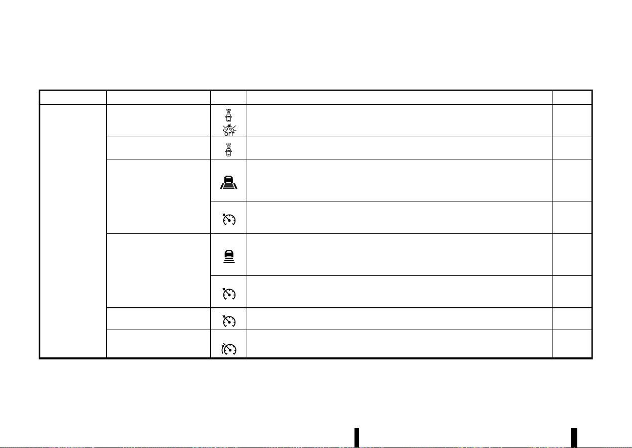
(266,1)
262 Starting and driving
Each Driver Assistance system is designed to help the driver in different ways as they drive. The following Driver Assistance systems (where fitted) are available on
this vehicle:
Category System Symbol System description (See the specified page for detailed information.)
Page
Forward Driving
Aids
Intelligent Emergency Braking
with Pedestrian Detection
Assists the driver with a warning and/or braking operation when there is a risk of a forward
collision with the vehicle ahead in the travelling lane, or with a pedestrian or a cyclist.
359
Intelligent Forward Collision
Warning
Helps alert the driver when there is a sudden braking of a second vehicle travelling in front of
the vehicle ahead in the same lane.
369
Intelligent Cruise Control (ICC)
(models with ProPILOT Assist
system)
Intelligent Cruise Control (ICC)
*
Helps the driver maintain a selected distance from the vehicle ahead and can reduce the
speed to match a slower vehicle ahead.
*
Decelerates the vehicle to a standstill when a vehicle ahead slows to a stop.
339
Conventional (fixed speed) cruise control mode
*
Allows the driver to drive the vehicle at a fixed speed without keeping his/her foot on the
accelerator pedal.
356
Intelligent Cruise Control (ICC)
(models without ProPILOT As-
sist system)
Intelligent Cruise Control (ICC)
*
Helps the driver maintain a selected distance from the vehicle ahead and can reduce the
speed to match a slower vehicle ahead.
*
Decelerates the vehicle to a standstill when a vehicle ahead slows to a stop.
313
Conventional (fixed speed) cruise control mode
*
Allows the driver to drive the vehicle at a fixed speed without keeping his/her foot on the
accelerator pedal.
326
Cruise control (models without
ProPILOT Assist system or ICC)
Allows the driver to drive the vehicle at a fixed speed without keeping his/her foot on the
accelerator pedal.
311
Speed limiter
Allow the driver to set the desired speed limit.
309
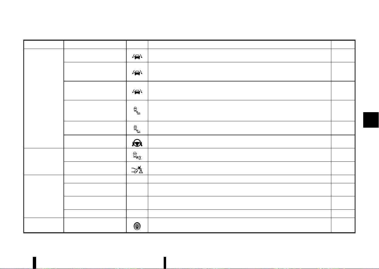
(267,1)
Category System Symbol System description (See the specified page for detailed information.)
Page
Side Driving Aids
(Lane and Blind
Spot)
Lane Departure Warning (LDW)
Warns the driver that the vehicle is about to cross a lane marker with an indicator and a
steering wheel vibration.
274
Intelligent Lane Intervention
*
Warns the driver that the vehicle is about to cross a lane marker with an indicator and a
steering wheel vibration.
*
Assists the driver to return the vehicle to the centre of the travelling lane.
277
Emergency Lane Assist (ELA)
*
Warns the driver when the vehicle approaches the road edge or solid white line with an
indicator and a steering wheel vibration.
*
Assist the driver to return the vehicle to the carriage way.
282
Blind Spot Warning (BSW)
Warns the driver of a vehicle in an adjacent lane when changing lanes with an indicator.
289
Intelligent Blind Spot Interven-
tion
*
Warns the driver of a vehicle in an adjacent lane when changing lanes.
*
Assists the driver to return the vehicle to the centre of the travelling lane.
295
Steering Assist
Assists the driver to help keep the vehicle within the centre of the travelling lane (this system is
integrated in the ProPILOT Assist system).
351
Rear Driving Aids
Rear Cross Traffic Alert (RCTA)
Assists the driver when reversingout from a parking space by detecting other vehicles
approaching from the right or left of the vehicle.
304
Rear Automatic Braking (RAB)
Assists the driver when the vehicle is reversing and approaching stationary objects directly
behind the vehicle by providing a warning and automatic braking if needed.
377
Parking Aids
Rear view monitor - Shows a rear view of the vehicle when the shift lever is placed in the R (Reverse) position.
185
Intelligent Around View Moni-
tor
-
Assists the driver in parking situations by showing various views of the position of the vehicle
in a split screen format.
191
Moving Object Detection
(MOD)
- Informs the driver of moving objects near the vehicle in parking situations.
200
Parking sensor (sonar) system - Informs the driver with a visual and audible alert of stationary obstacles near the bumpers.
395
ProPILOT Assist ProPILOT Assist
Consists of Intelligent Cruise Control (ICC) and Steering Assist.
329
Starting and driving 263
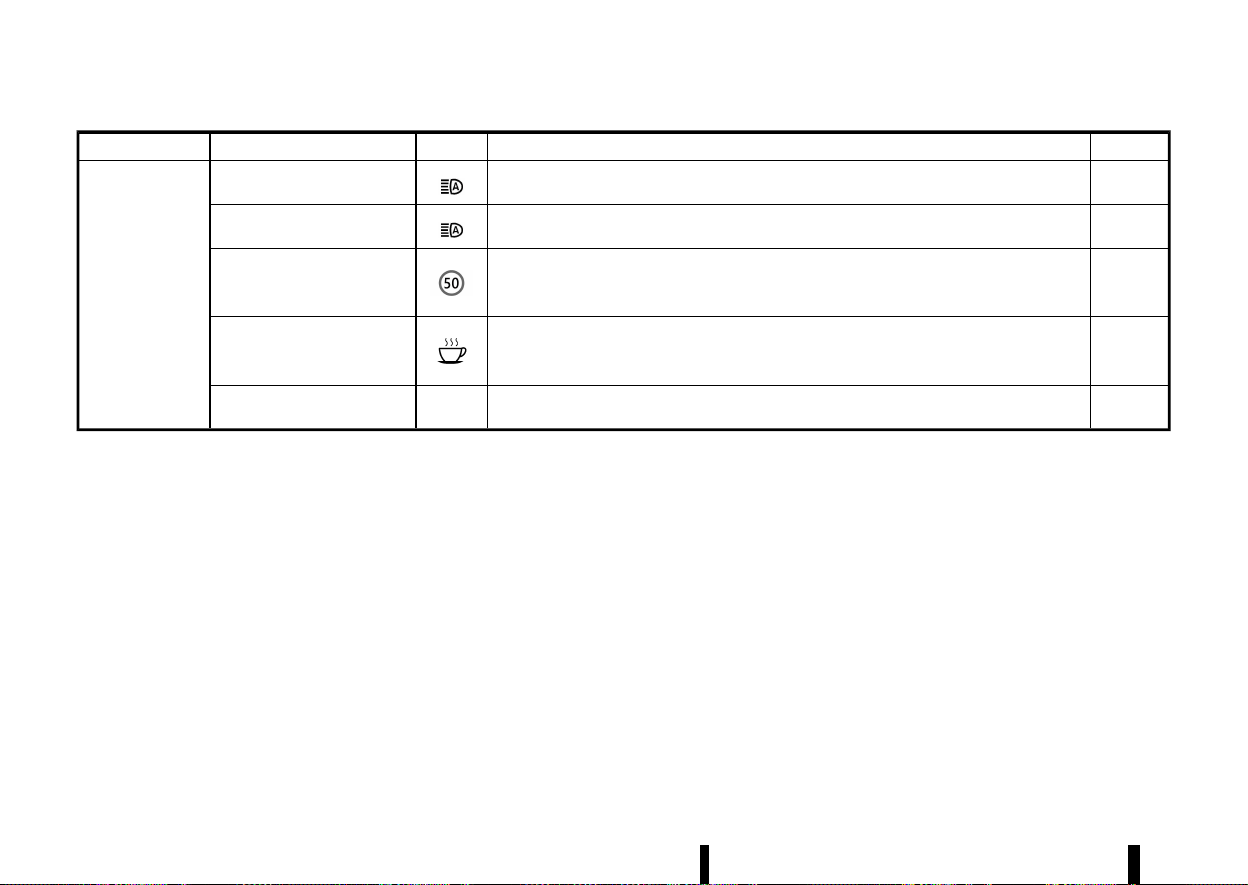
(268,1)
264 Starting and driving
Category System Symbol System description (See the specified page for detailed information.)
Page
Other Driving Aids
High beam assist
Switches the headlights to the low beam automatically when an oncoming vehicle or leading
vehicle appears in front of your vehicle.
109
Adaptive LED headlight
Changes the area illuminated by the headlights automatically when an oncoming vehicle or
leading vehicle appears in front of your vehicle.
110
Traffic Sign Recognition (TSR)
Provides the driver with information about the most recently detected speed limit.
271
Intelligent Driver Alertness
Helps alert the driver when a lack of attention or driving fatigue is detected.
375
Hill Start Assist -
Helps prevent the vehicle from rolling backwards in the time it takes the driver to release the
brake pedal and apply the accelerator when the vehicle is stopped on a hill.
394
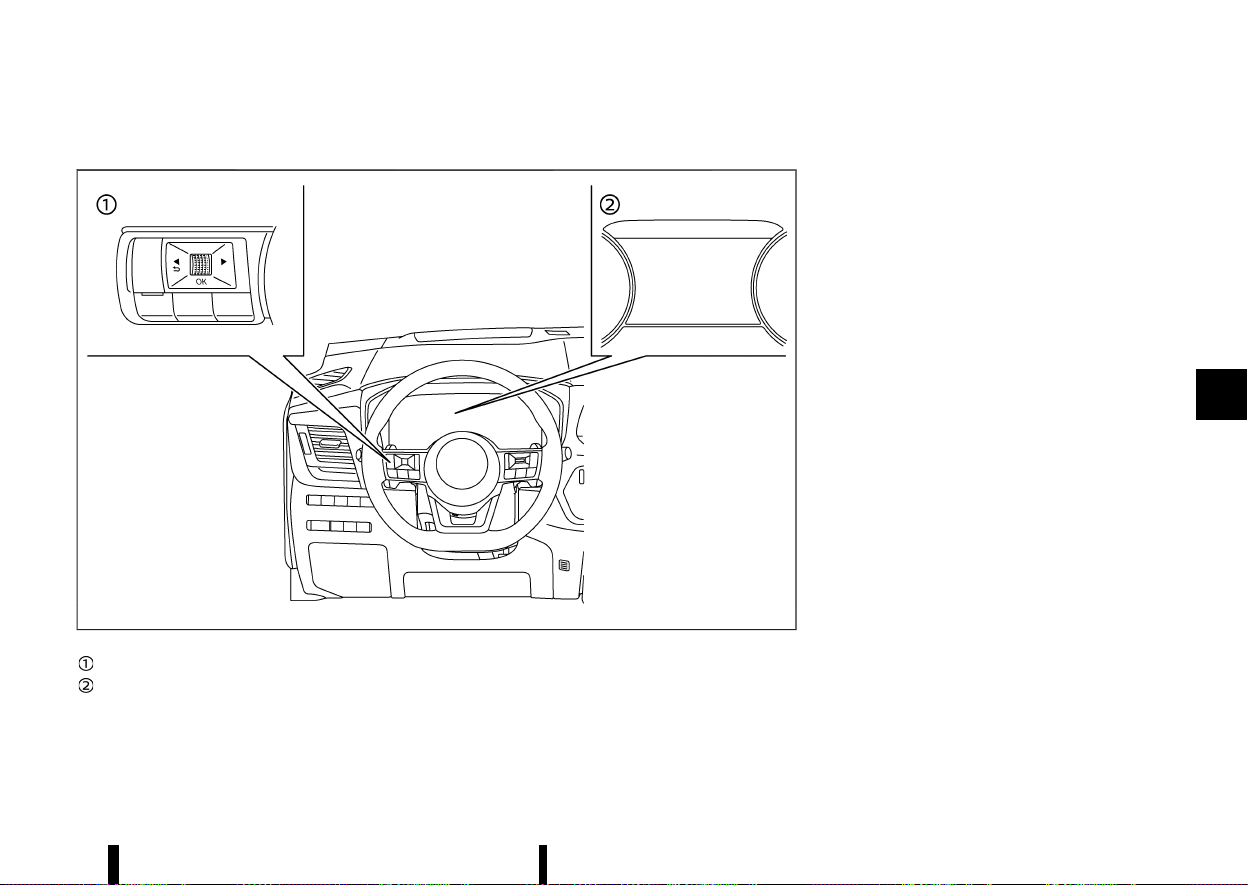
(269,1)
HOW TO ENABLE/DISABLE THE SYSTEMS
MEVT33A1-BE4C2AD1-73BF-4C82-89CB-42B01D28485A
MWAF0412X
Steering-wheel-mounted controls (left side)
Vehicle information display
The following systems (where fitted) can be
enabled or disabled using the settings menu in
the vehicle information display. Select each setting
item using the scroll dial on the steering-wheel-
mounted controls.
* Intelligent Emergency Braking with Pedestrian
Detection
* Intelligent Forward Collision Warning
* Lane Departure Warning (LDW)
* Intelligent Lane Intervention*
* Emergency Lane Assist (ELA) system
* Blind Spot Warning (BSW)
* Intelligent Blind Spot Intervention*
* Speed Limit Link
* CRUISE Navi Link
* Steering Assist
* Rear Cross Traffic Alert (RCTA)
* Rear Automatic Braking (RAB)
* Moving Object Detection (MOD)
* Parking sensor (sonar) system
* Traffic Sign Recognition (TSR)
* Intelligent Driver Alertness
*: To operate the Intelligent Lane Intervention and
Intelligent Blind Spot Intervention systems, you
need to push the ProPILOT Assist switch or the
dynamic driver assistance switch after enabling
each system in the settings menu.
Driver Assistance display
MEVT33A1-708E1D0D-89DE-4D7F-B0E5-83912A5C69D7
The Driver Assistance display appears in the
vehicle information display when selected using
the scroll dial, or for a short period of time when
the ProPILOT switch (where fitted) is pushed.
The status of the following systems (where fitted)
can be shown in each zone of the display.
Starting and driving 265
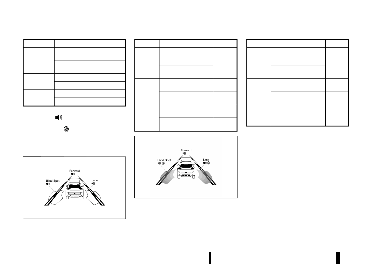
(270,1)
266 Starting and driving
Zone
Driving Aid
Forward
Intelligent Emergency Braking with
Pedestrian Detection
Intelligent Forward Collision Warn-
ing
Lane
Lane Departure Warning (LDW)
Intelligent Lane Intervention
Blind Spot
Blind Spot Warning (BSW)
Intelligent Blind Spot Intervention
* When any of the “Warning” systems are en-
abled, the “
” mark is shown in each zone.
* When any of the “Intervention” systems are
enabled, the “
” mark is shown in each
zone.
* When no system is enabled, “OFF” is shown in
each zone.
The display changes as the following examples:
MWAF0522X
Zone Driving Aid
Status
Forward
Intelligent Emergency
Braking with Pedestrian
Detection
Enabled
(outline)
Intelligent Forward Colli-
sion Warning
Lane
Lane Departure Warning
(LDW)
Enabled
(outline)
Intelligent Lane Interven-
tion
Disabled
Blind Spot
Blind Spot Warning (BSW)
Enabled
(outline)
Intelligent Blind Spot Inter-
vention
Disabled
MWAF1248X
Zone Driving Aid
Status
Forward
Intelligent Emergency
Braking with Pedestrian
Detection
Enabled
(outline)
Intelligent Forward Colli-
sion Warning
Lane
Lane Departure Warning
(LDW)
Enabled
Intelligent Lane Interven-
tion
Enabled
(shaded)
Blind Spot
Blind Spot Warning (BSW)
Enabled
Intelligent Blind Spot Inter-
vention
Enabled
(shaded)

(271,1)
COMMON TROUBLESHOOTING GUIDE
MEVT33A1-4A828657-24DF-40EA-873A-7D3F74310D76
Some of the Driver Assistance systems use the common parts (camera, radar, etc.) to function. When a pop-up warning message appears in the vehicle
information display, or the warning light flashes/illuminates, check the system condition. For details, see [System temporarily unavailable] and [System
malfunction] sections in this Owner’s Manual for each applicable system.
For camera and radar temporary blockage
Warning message/Warn-
ing light
Symptom Possible cause System affected
Action to take
[Unavailable
Camera Temperature
High]
High camera
temperature
Direct sunlight/High cabin
temperature
TSR, LDW, Intelligent
Lane Intervention, In-
telligent Blind Spot In-
tervention and
Steering Assist
When the interior temperature is reduced, the system resumes
automatically. (Push the ProPILOT Assist switch or the dynamic
driver assistance switch to turn back on the Intelligent Lane
Intervention and Intelligent Blind Spot Intervention systems.)
Flashing
Intelligent Emergency
Braking with Pedes-
trian Detection and
Intelligent Forward
Collision Warning
[Unavailable
Low Visibility]
or
Flashing
Poor camera
visibility
Direct sunlight
ELA, Steering Assist
and Intelligent Emer-
gency Braking with
Pedestrian Detection
When the condition no longer exists, the system resumes auto-
matically.
Camera
obstruction
Windscreen glass misted, fro-
zen or covered with dirt
Clean the windscreen glass of the camera area. Use the wipers and
the defogger to help clear the windscreen glass.
[Not Available
Visibility is impaired]
Poor visibility/
Undetectable
lane marker
Bad weather Steering Assist
When the condition no longer exists, push the ProPILOT Assist
switch to turn off the ProPILOT Assist system and push the switch
again to turn back on the system.
Starting and driving 267

(272,1)
268 Starting and driving
Warning message/Warn-
ing light
Symptom Possible cause System affected
Action to take
[Temporarily Disabled
Front Radar Blocked]
and
Flashing (only Intelli-
gent Emergency Braking)
Front radar ob-
struction
Inclement weather (rain, fog,
snow, etc.)
ELA, ICC, ProPILOT As-
sist, Intelligent Emer-
gency Braking with
Pedestrian Detection
and Intelligent For-
ward Collision Warn-
ing
When the condition no longer exists, the system resumes auto-
matically. (Push the ProPILOT Assist switch or Cruise ON/OFF
switch to turn back on the ICC system.)
Sensor covered with dirt or
obstructed
Clean the front radar sensor area on the front of the vehicle.
Roads with limited road struc-
tures or buildings
When the condition no longer exists, the system resumes auto-
matically. (Push the ProPILOT Assist switch or Cruise ON/OFF
switch to turn back on the ICC system.)
Flashing (only Intelli-
gent Emergency Braking)
Front radar in-
terruption
Interference from another ra-
dar source
ICC, ProPILOT Assist,
Intelligent Emergency
Braking with Pedes-
trian Detection and
Intelligent Forward
Collision Warning
When the condition no longer exists, the system resumes auto-
matically. (Push the ProPILOT Assist switch or Cruise ON/OFF
switch to turn back on the ICC system.)
[Not available
Side radar
obstructed]
Side radar ob-
struction
Radar blockage
ELA, BSW, Intelligent
Blind Spot Interven-
tion and RCTA
Clean the side rear radar area on the rear of the vehicle. When the
condition no longer exists, the system resumes automatically. (Push
the ProPILOT Assist switch or dynamic driver assistance switch to
turn back on the Intelligent Blind Spot Intervention.)
[Unavailable
Slippery Road]
Poor road con-
dition
Slippery road
Intelligent Lane Inter-
vention, Intelligent
Blind Spot Interven-
tion, ICC and ProPILOT
Assist
When the condition no longer exists, push the ProPILOT Assist
switch or the dynamic driver assistance switch or the Cruise ON/
OFF switch to turn back on each system.
[Not Available,
Parking Brake On]
System cancel
Electronic parking brake ap-
plication
ProPILOT Assist
When the condition no longer exists, push the ProPILOT Assist
switch to turn off the ICC system and push the switch again to turn
back on the ICC system.
[Press brake pedal]
No electronic
parking brake
application
Driver’s door open (vehicle
stopped)
ProPILOT Assist
Step on the brake pedal immediately.
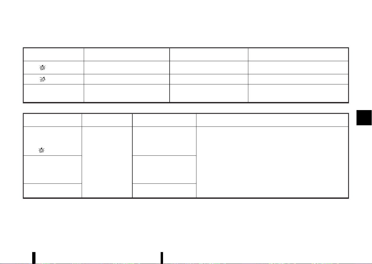
(273,1)
For system temporarily unavailable
Warning light/Warning mes-
sage
Possible cause System to check
Action to take
Illuminating
VDC/ESP turned off
Intelligent Emergency Braking with Pe-
destrian Detection
Turn on the VDC/ESP.
Illuminating
VDC/ESP turned off RAB
Turn on the VDC/ESP.
[Currently Not Available] VDC/ESP turned off
Intelligent Lane Intervention, Intelligent
Blind Spot Intervention, ICC and ProPI-
LOT Assist
Turn on the VDC/ESP.
For system malfunction
Warning light/Warning mes-
sage
Symptom System to check
Action to take
[System fault
See Owner’s Manual]
and
Illuminating
System malfunction
Intelligent Emergency Braking
with Pedestrian Detection and
Intelligent Forward Collision
Warning
Stop the vehicle in a safe location. Turn the engine off and restart the engine. If
the warning light/message continues to illuminate, have the system checked. It
is recommended that you visit a NISSAN dealer or qualified workshop for this
service.
[System fault
See Owner’s Manual]
TSR, RAB, LDW, Intelligent Lane
Intervention, ELA, BSW, Intelli-
gent Blind Spot Intervention,
RCTA, ICC, Steering Assist and
Intelligent Driver Alertness
[Parking Sensor system fault
See Owner’s Manual]
Parking sensor (sonar) system
Starting and driving 269
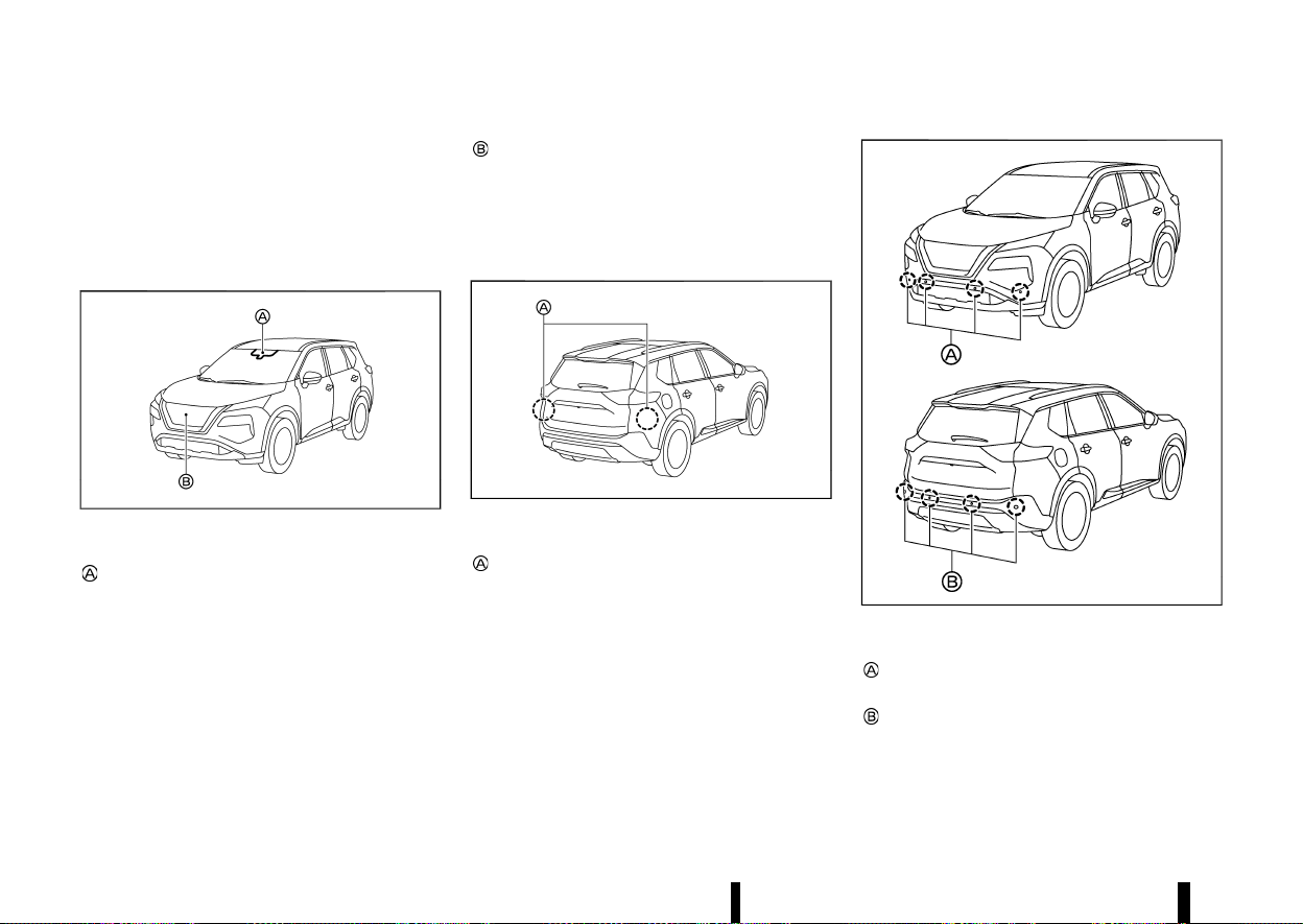
(274,1)
270 Starting and driving
Camera, radar and sonar locations
MEVT33A1-38474CE5-C43E-420C-9825-BBC143C229F9
The camera, radar and parking sensors that are
used by each Driver Assistance systems are
located on the front and rear of the vehicle. For
the maintenance of each component, see “System
maintenance” section in this Owner’s Manual for
each application system.
MWAF0644X
Vehicle front
Front camera unit
— Intelligent Emergency Braking with Pedes-
trian Detection
— Lane Departure Warning (LDW)
— Intelligent Lane Intervention
— Intelligent Blind Spot Intervention
— Steering Assist
— Emergency Lane Assist (ELA)
— High beam assist
— Adaptive LED headlight
— Traffic Sign Recognition (TSR)
Front radar sensor
— Intelligent Emergency Braking with Pedes-
trian Detection
— Intelligent Forward Collision Warning
— Intelligent Cruise Control (ICC)
— Emergency Lane Assist (ELA)
MWAF0414X
Vehicle rear
Side radar sensor
— Blind Spot Warning (BSW)
— Intelligent Blind Spot Intervention
— Rear Cross Traffic Alert (RCTA)
— Emergency Lane Assist (ELA)
MWAF0839X
Parking sensors
Front parking sensors (where fitted)
— Parking sensor (sonar) system
Rear parking sensors
— Rear Automatic Braking (RAB)
— Parking sensor (sonar) system
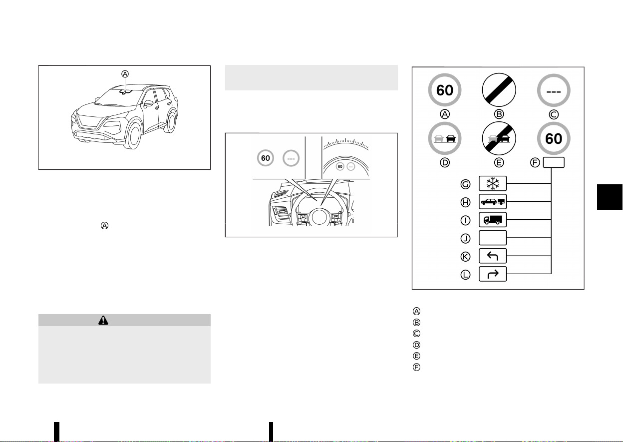
(275,1)
MEVT33A1-C31AE55D-A0B2-44AF-892B-5A8D348A5534
MWAC0523X
The Traffic Sign Recognition (TSR) system provides
the driver with information about the most re-
cently detected speed limit. The system captures
the road sign information with the multi-sensing
front camera unit
located on the windscreen in
front of the inside rearview mirror and displays the
detected signs in the vehicle information display.
For vehicles equipped with navigation system, the
speed limit displayed is based on a combination of
navigation system data and live camera recogni-
tion. TSR information is shown in the vehicle
information display and in the Head Up Display
(HUD) (where fitted). (See “[Head Up Display (HUD)]
(where fitted)” (P.105).)
WARNING
The TSR system is only intended to be a
support device to provide the driver with
information. It is not a replacement for the
driver’s attention to traffic conditions or re-
sponsibility to drive safely. It cannot prevent
accidents due to carelessness. It is the driver’s
responsibility to stay alert and drive safely at
all times.
SYSTEM OPERATION
MEVT33A1-DE7ADF81-0872-42F8-8611-5256949366F5
The TSR system displays the following types of
road sign:
MWAF1202X
Example
MWBF0173X
Available road signs
Latest detected speed limit
National speed limit
No speed limit information
No-overtaking zone
End of no-overtaking zone
Conditional speed limit, with the following
available conditions:
Starting and driving 271
TRAFFIC SIGN RECOGNITION (TSR)
TRAFFIC SIGN RECOGNITION (TSR)

(276,1)
272 Starting and driving
Snow
Towing
Goods vehicles
Generic
Left turn allowed
Right turn allowed
CAUTION
* The TSR system is intended as an aid to
careful driving. It is the driver’s responsi-
bility to stay alert, drive safely, and observe
all road regulations that currently apply,
including looking out for road signs.
* The TSR system may not function properly
under all conditions. Below are some ex-
amples:
— When rain, snow or dirt adheres to the
windscreen in front of the multi-sen-
sing front camera unit.
— When the headlights are not bright
due to dirt on the lens or if the aiming
is not adjusted properly.
— When strong light enters the camera
unit. (For example, the light directly
shines on the front of the vehicle at
sunrise or sunset.)
— When a sudden change in brightness
occurs. (For example, when the vehicle
enters or exits a tunnel or under a
bridge.)
— When there is poor visibility. (For
example, insufficient illumination of
the road, bad weather conditions in
rain, snow, fog or heavy spray.)
— When the traffic signs are damaged or
not standard. (For example, incorrect
size, height, direction or brightness,
broken or bent.)
— When the traffic signs are hard to
detect. (For example, they are covered
by dirt or snow, or insufficient light-
ing.)
— When the traffic signs are ambiguous.
(For example, traffic signs on con-
struction sites, in adjacent lanes or
exit lane.)
— When there is an object similar to
traffic signs. (For example, similar
signs, board or structure.)
— When passing traffic signs are outside
the camera’s field of vision. (For ex-
ample, after a sharp turn or located
too far away.)
— When electric traffic signs are hard to
detect. (For example, low contrast,
located too far away or 3 digits.)
— In areas not covered by the navigation
system (where fitted).
— If there are deviations in relation to the
navigation (where fitted), for example
due to changes in the road routing.
— When overtaking buses or trucks with
speed stickers.
— When the data from the navigation
system (where fitted) is not up-to-date
or is unavailable.
* The TSR system may display a traffic sign,
even though there is no traffic sign in front
of the vehicle. It may display a different
speed limit from that for a passenger
vehicle. (The maximum speed limit sign
may show a higher or lower number than
the actual maximum speed, for example,
when detecting a speed limit sign for
trucks, different speed limit with the time
of day or day of the week, or speed limit
sign using different units near a border,
when detecting an electric traffic sign with
or without speed limit indication, when
detecting an irrelevant speed limit passing
by a freeway exit or junction, etc.)
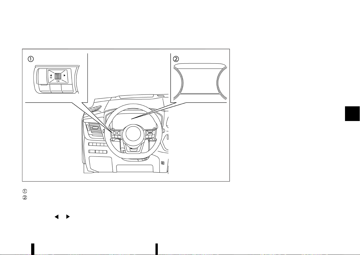
(277,1)
HOW TO ENABLE/DISABLE THE TSR SYSTEM
MEVT33A1-3777B924-8AD0-4710-B9F3-4B1241D07D55
MWAF0412X
Steering-wheel-mounted controls (left side)
Vehicle information display
Perform the following steps to enable or disable
the TSR system:
1. Push the
button until [Settings]
appears in the vehicle information display
and then push the scroll dial. Use the scroll
dial to select [Driver Assistance]. Then push the
scroll dial.
2. Select [Traffic Sign] and push the scroll dial to
turn the system on or off.
SYSTEM TEMPORARILY UNAVAILABLE
MEVT33A1-9058E119-446B-434E-BD99-CAD2DC59B851
If the vehicle is parked in direct sunlight under high
temperature conditions (over approximately 40°C
(104°F) and then started, the TSR system may be
deactivated automatically.
Action to take:
When the interior temperature is reduced, the TSR
system will resume operating automatically.
SYSTEM MALFUNCTION
MEVT33A1-C3713FD9-1E4C-4F45-B58F-2225F637F9A4
If the TSR system malfunctions it will be turned off
automatically and the [System fault See Owner’s
Manual] warning message will appear in the
vehicle information display.
Action to take
If the warning message appears, pull off the road
at a safe location and stop the vehicle. Turn the
engine off and restart the engine. If the warning
message continues to appear, have the system
checked by a NISSAN dealer or qualified workshop.
SYSTEM MAINTENANCE
MEVT33A1-CC87EEFA-83F5-4624-98B4-21BE451F25DF
The TSR system uses the same multi-sensing front
camera unit that is used by the Lane Departure
Warning (LDW) system, located in front of the
inside rearview mirror. For maintenance of the
camera, see “System maintenance” (P.277).
Starting and driving 273
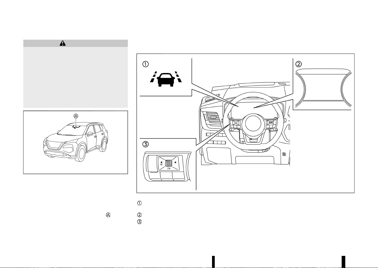
(278,1)
274 Starting and driving
MEVT33A1-F1C5BE72-5071-47A9-9477-0560B1FE4104
WARNING
Failure to follow the warnings and instructions
for proper use of the LDW system could result
in serious injury or death.
* This system is only a warning device to
inform the driver of a potential unintended
lane departure. It will not steer the vehicle
or prevent loss of control. It is the driver’s
responsibility to stay alert, drive safely,
keep the vehicle in the travelling lane,
and be in control of the vehicle at all times.
MWAC0523X
The LDW system will operate when the vehicle is
driven at speeds of approximately 60 km/h (37
MPH) and above, and the lane markings are clearly
visible on the road.
The LDW system monitors the lane markers on the
travelling lane using the camera unit
located
above the inside rearview mirror.
The LDW system warns the driver that the vehicle
is beginning to leave the driving lane with an
indicator and a steering wheel vibration. (See “LDW
system operation” (P.274).)
MWAF0411X
LDW indicator (on the vehicle information
display)
Vehicle information display
Steering-wheel-mounted controls (left side)
LDW SYSTEM OPERATION
MEVT33A1-F46828E8-1A68-4EAF-AE01-2B1A3300C39D
The LDW system provides a lane departure warn-
ing function when the vehicle is driven at speeds of
approximately 60 km/h (37 MPH) and above and
the lane markings are clear. When the vehicle
approaches either the left or the right side of the
LANE DEPARTURE WARNING
(LDW) (where fitted)
LANE DEPARTURE WARNING
(LDW) (where fitted)
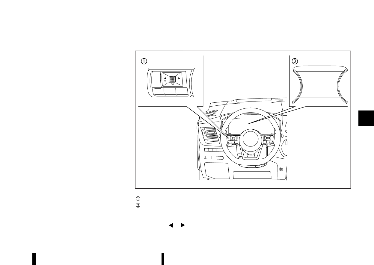
(279,1)
travelling lane, the steering wheel will vibrate and
the LDW indicator on the vehicle information
display will blink to alert the driver.
The warning function will stop when the vehicle
returns inside of the lane markers.
The strength of the steering wheel vibration can
be changed in the settings menu of the vehicle
information display. (See “[Driver Assistance]”
(P.83).)
HOW TO ENABLE/DISABLE THE LDW SYSTEM
MEVT33A1-91834683-7C72-4825-BFD6-7CE9FFF91369
MWAF0412X
Steering-wheel-mounted controls (left side)
Vehicle information display
Perform the following steps to enable or disable
the LDW system.
1. Push the
button until [Settings]
appears in the vehicle information display
and then push the scroll dial. Use the scroll
dial to select [Driver Assistance]. Then push the
scroll dial.
2. Select [Lane] and push the scroll dial.
3. Select [Warning] and push the scroll dial.
Starting and driving 275

(280,1)
276 Starting and driving
NOTE:
If you disable the LDW system, the system will
remain disabled the next time you start the
engine.
LDW SYSTEM LIMITATIONS
MEVT33A1-86446026-AA69-4CD4-9090-98FD0C3E91C2
WARNING
Listed below are the system limitations for the
LDW system. Failure to follow the warnings and
instructions for proper use of the LDW system
could result in serious injury or death.
* The system will not operate at speeds
below approximately 60 km/h (37 MPH)
or if it cannot detect lane markers.
* Do not use the LDW system under the
following conditions as it may not function
properly:
— During bad weather (rain, fog, snow,
etc.).
— When driving on slippery roads, such
as on ice or snow.
— When driving on winding or uneven
roads.
— When there is a lane closure due to
road repairs.
— When driving in a makeshift or tem-
porary lane.
— When driving on roads where the lane
width is too narrow.
— When driving without normal tyre
conditions (for example, tyre wear,
low tyre pressure, tyre chains, non-
standard wheels).
— When the vehicle is equipped with
non-original brake parts or suspen-
sion parts.
— When towing a trailer or other vehicle.
* The system may not function properly
under the following conditions:
— On roads where there are multiple
parallel lane markers; lane markers
that are faded or not painted clearly;
yellow painted lane markers; non-
standard lane markers; or lane mar-
kers covered with water, dirt, snow,
etc.
— On roads where discontinued lane
markers are still detectable.
— On roads where there are sharp
curves.
— On roads where there are sharply
contrasting objects, such as shadows,
snow, water, wheel ruts, seams or lines
remaining after road repairs. (The LDW
system could detect these items as
lane markers.)
— On roads where the travelling lane
merges or separates.
— When the vehicle’s travelling direction
does not align with the lane marker.
— When travelling close to the vehicle in
front of you, which obstructs the lane
camera unit detection range.
— When rain, snow, dirt or object adheres
to the windscreen in front of the lane
camera unit.
— When the headlights are not bright
due to dirt on the lens or if the aiming
is not adjusted properly.
— When strong light enters the lane
camera unit. (For example, the light
directly shines on the front of the
vehicle at sunrise or sunset.)
— When a sudden change in brightness
occurs. (For example, when the vehicle
enters or exits a tunnel or under a
bridge.)
SYSTEM TEMPORARILY UNAVAILABLE
MEVT33A1-340896DE-B513-4899-9380-373C7E0C9B1B
Condition A:
If the vehicle is parked in direct sunlight under high
temperature conditions (over approximately 40°C
(104°F)) and then started, the LDW system may be
deactivated automatically and the following mes-
sage will appear in the vehicle information display.
* [Unavailable Camera Temperature High]
When the interior temperature is reduced, the LDW
system will resume operating automatically.
Condition B:
The warning function of the LDW system is not
designed to work under the following conditions:
* When you operate the lane change signal and
change travelling lanes in the direction of the
signal. (The LDW system will become operable

(281,1)
again approximately 2 seconds after the lane
change signal is turned off.)
* When the vehicle speed lowers to less than
approximately 60 km/h (37 MPH).
Action to take:
After the above conditions have finished and the
necessary operating conditions are satisfied, the
LDW system will resume.
SYSTEM MALFUNCTION
MEVT33A1-A96652FC-A027-4283-A00B-7A1F20645CF4
If the LDW system malfunctions, it will cancel
automatically and [System fault See Owner’s
Manual] warning message will appear in the
vehicle information display. If the warning mes-
sage appears, pull off the road to a safe location
and stop the vehicle. Place the ignition switch in
the “OFF” position and restart the engine. If the
warning message continues to appear, have the
system checked. It is recommended that you visit a
NISSAN dealer or qualified workshop for this
service.
SYSTEM MAINTENANCE
MEVT33A1-69E222DB-DF19-43C2-B843-822D55DC25F5
MWAC0523X
The lane camera unit for the LDW system is
located above the inside rearview mirror.
To keep the proper operation of the LDW system
and prevent a system malfunction, be sure to
observe the following:
* Always keep the windscreen clean.
* Do not attach a sticker (including transparent
material) or install an accessory near the
camera unit.
* Do not place reflective materials, such as white
paper or a mirror, on the instrument panel.
The reflection of sunlight may adversely affect
the camera unit’s capability of detecting the
lane markers.
* Do not strike or damage the areas around the
camera unit. Do not touch the camera lens or
remove the screw located on the camera unit.
If the camera unit is damaged due to an
accident, it is recommended that you visit a
NISSAN dealer or qualified workshop.
MEVT33A1-E98FFDFE-96B4-4FBE-A42A-1BDB73E1E3D4
WARNING
Failure to follow the warnings and instructions
for proper use of the Intelligent Lane Interven-
tion system could result in serious injury or
death.
* The Intelligent Lane Intervention system
will not steer the vehicle or prevent loss of
control. It is the driver’s responsibility to
stay alert, drive safely, keep the vehicle in
the travelling lane, and be in control of the
vehicle at all times.
* The Intelligent Lane Intervention system is
primarily intended for use on well-devel-
oped freeways or highways. It may not
detect the lane markers in certain road,
weather, or driving conditions.
MWAC0523X
The Intelligent Lane Intervention system must be
turned on with the ProPILOT Assist switch (where
fitted) or the dynamic driver assistance switch
Starting and driving 277
INTELLIGENT LANE INTERVEN-
TION (where fitted)
INTELLIGENT LANE INTERVEN-
TION (where fitted)
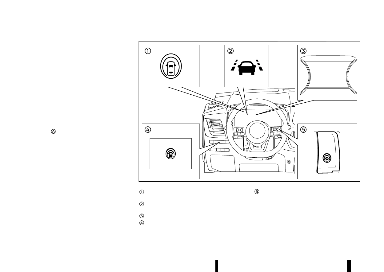
(282,1)
278 Starting and driving
(where fitted) on the steering wheel, every time the
ignition is placed in the ON position.
The Intelligent Lane Intervention system will oper-
ate when the vehicle is driven at speeds of
approximately 60 km/h (37 MPH) and above, and
only when the lane markings are clearly visible on
the road. The Intelligent Lane Intervention system
warns the driver when the vehicle has left the
centre of the travelling lane with an indicator and
steering wheel vibration. The system helps assist
the driver to return the vehicle to the centre of the
travelling lane by applying the brakes to the left or
right wheels individually (for a short period of time).
The Intelligent Lane Intervention system monitors
the lane markers on the travelling lane using the
camera unit
located above the inside rearview
mirror.
MWAF1199X
Intelligent Lane Intervention ON indicator (on
the vehicle information display)
Intelligent Lane Intervention indicator (on
the vehicle information display)
Vehicle information display
Dynamic driver assistance switch (models
without ProPILOT Assist system)
ProPILOT Assist switch (models with ProPI-
LOT Assist system)
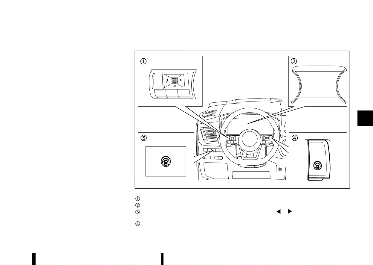
(283,1)
INTELLIGENT LANE INTERVENTION SYS-
TEM OPERATION
MEVT33A1-7943DDF1-EA65-46F3-B4CA-4FB4928D4325
The Intelligent Lane Intervention system operates
above approximately 60 km/h (37 MPH) and when
the lane markings are clear. When the vehicle
approaches either the left or the right side of the
travelling lane, steering wheel will vibrate and the
Intelligent Lane Intervention indicator (yellow) on
the vehicle information display will blink to alert
the driver. Then, the Intelligent Lane Intervention
system will automatically apply the brakes for a
short period of time to help assist the driver to
return the vehicle to the centre of the travelling
lane.
To turn on the Intelligent Lane Intervention
system, push the ProPILOT Assist switch on the
steering wheel (where fitted) or the dynamic driver
assistance switch on the driver’s side instrument
panel (where fitted) after starting the engine. The
Intelligent Lane Intervention ON indicator on the
vehicle information display will illuminate. Push the
ProPILOT Assist switch (where fitted) or the
dynamic driver assistance switch (where fitted)
again to turn off the Intelligent Lane Intervention
system. The Intelligent Lane Intervention ON
indicator will turn off.
The strength of the steering wheel vibration can
be changed in the settings menu of the vehicle
information display. (See “[Driver Assistance]”
(P.83).)
HOW TO ENABLE/DISABLE THE INTELLIGENT LANE INTERVENTION SYSTEM
MEVT33A1-F785D289-303F-4F8F-A710-4615BB3FDC9A
MWAF1200X
Steering-wheel-mounted control (left side)
Vehicle information display
Dynamic driver assistance switch (models
without ProPILOT Assist system)
ProPILOT Assist switch (models with ProPI-
LOT Assist system)
Perform the following steps to enable or disable
the Intelligent Lane Intervention system.
1. Push the
button until [Settings] ap-
pears in the vehicle information display and
then push the scroll dial. Use the scroll dial to
select [Driver Assistance]. Then push the scroll
dial.
Starting and driving 279

(284,1)
280 Starting and driving
2. Select [Lane] and push the scroll dial.
3. Select [Intervention] and push the scroll dial.
4. Push the ProPILOT Assist switch (where fitted)
or the dynamic driver assistance switch
(where fitted) to turn the system on or off.
NOTE:
* Turning on the ProPILOT Assist system
(where fitted) will turn on the Intelligent
Lane Intervention system and Intelligent
Blind Spot Intervention system (where
fitted) at the same time. If the Intelligent
Lane Intervention system is disabled in the
settings menu, the Intelligent Lane Interven-
tion will automatically be turned on when
the Steering Assist system is active. (See
“ProPILOT Assist (where fitted)” (P.329).)
* For model with ProPILOT Assist system:
When the Intelligent Lane Intervention sys-
tem is enabled in the settings menu, the
Intelligent Lane Intervention system can be
turned on or off by pushing the speed limiter
MAIN switch
(where fitted).
INTELLIGENT LANE INTERVENTION SYS-
TEM LIMITATIONS
MEVT33A1-E4DC4C45-05C8-4605-9BFA-FA8900BE9CF9
WARNING
Listed below are the system limitations for the
Intelligent Lane Intervention system. Failure to
follow the warnings and instructions for prop-
er use of the Intelligent Lane Intervention
system could result in serious injury or death.
* The Intelligent Lane Intervention system
may activate if you change lanes without
first activating your turn signal or, for
example, if a construction zone directs
traffic to cross an existing lane marker. If
this occurs you may need to apply correc-
tive steering to complete your lane
change.
* Because the Intelligent Lane Intervention
may not activate under the road, weather,
and lane marker conditions described in
this section, it may not activate every time
your vehicle begins to leave its lane and
you will need to apply corrective steering.
* The Intelligent Lane Intervention system
will not operate at speeds below approxi-
mately 60 km/h (37 MPH) or if it cannot
detect lane markers.
* When the Intelligent Lane Intervention
system is operating, avoid excessive or
sudden steering manoeuvres. Otherwise,
you could lose control of the vehicle.
* Do not use the Intelligent Lane Interven-
tion system under the following conditions
as it may not function properly:
— During bad weather (rain, fog, snow,
etc.).
— When driving on slippery roads, such
as on ice or snow.
— When driving on winding or uneven
roads.
— When there is a lane closure due to
road repairs.
— When driving in a makeshift or tem-
porary lane.
— When driving on roads where the lane
width is too narrow.
— When driving without normal tyre
conditions (for example, tyre wear,
low tyre pressure, tyre chains, non-
standard wheels).
— When the vehicle is equipped with
non-original brake parts or suspen-
sion parts.
— When towing a trailer or other vehicle.
— On roads where there are multiple
parallel lane markers; lane markers
that are faded or not painted clearly;
yellow painted lane markers; non-
standard lane markers; or lane mar-
kers covered with water, dirt, snow,
etc.
— On roads where discontinued lane
markers are still detectable.
— On roads where there are sharp
curves.
— On roads where there are sharply
contrasting objects, such as shadows,
snow, water, wheel ruts, seams or lines
remaining after road repairs. (The In-
telligent Lane Intervention system
could detect these items as lane mar-
kers.)
— On roads where the travelling lane
merges or separates.
— When the vehicle’s travelling direction
does not align with the lane marker.

(285,1)
— When travelling close to the vehicle in
front of you, which obstructs the lane
camera unit detection range.
— When rain, snow or dirt adheres to the
windscreen in front of the lane camera
unit.
— When the headlights are not bright
due to dirt on the lens or if the aiming
is not adjusted properly.
— When strong light enters the lane
camera unit. (For example, the light
directly shines on the front of the
vehicle at sunrise or sunset.)
— When a sudden change in brightness
occurs. (For example, when the vehicle
enters or exits a tunnel or under a
bridge.)
While the Intelligent Lane Intervention system is
operating, you may hear a sound of brake opera-
tion. This is normal and indicates that the Intelli-
gent Lane Intervention system is operating
properly.
SYSTEM TEMPORARILY UNAVAILABLE
MEVT33A1-784B5E76-960C-4FD7-A89B-588AE7CFDB88
Condition A:
The warning and assist functions of the Intelligent
Lane Intervention system are not designed to work
under the following conditions:
* When you operate the lane change signal and
change the travelling lanes in the direction of
the signal. (The Intelligent Lane Intervention
system will be deactivated for approximately 2
seconds after the lane change signal is turned
off.)
* When the vehicle speed lowers to less than
approximately 60 km/h (37 MPH).
Action to take:
After the above conditions have finished and the
necessary operating conditions are satisfied, the
warning and assist functions will resume.
Condition B:
The assist function of the Intelligent Lane Inter-
vention system is not designed to work under the
following conditions (warning is still functional):
* When the brake pedal is depressed.
* When the steering wheel is turned as far as
necessary for the vehicle to change lanes.
* When the vehicle is accelerated during the
Intelligent Lane Intervention system operation.
* When the hazard warning flashers are oper-
ated.
* When driving on a curve at high speed.
Action to take:
After the above conditions have finished and the
necessary operating conditions are satisfied, the
Intelligent Lane Intervention system application of
the brakes will resume.
Condition C:
If the following message appears in the vehicle
information display, a chime will sound and the
Intelligent Lane Intervention system will be turned
off automatically.
* [Unavailable Slippery Road]:
— When the VDC/ESP (except Traction Control
System (TCS) function) system or ABS
operates.
* [Currently Not Available]:
— When the VDC/ESP system is turned off.
Action to take:
When the above conditions no longer exist, turn off
the Intelligent Lane Intervention system. Push the
ProPILOT Assist switch (where fitted) or the
dynamic driver assistance switch (where fitted)
again to turn the Intelligent Lane Intervention
system back on.
Temporary disabled status at high temperature:
If the vehicle is parked in direct sunlight under high
temperature conditions (over approximately 40°C
(104°F)) and then the Intelligent Lane Intervention
system is turned on, the Intelligent Lane Interven-
tion system may be deactivated automatically, a
chime sounds and the following message will
appear on the vehicle information display:
* [Unavailable Camera Temperature High]
When the interior temperature is reduced, turn off
the Intelligent Lane Intervention system. Push the
ProPILOT Assist switch (where fitted) or the
dynamic driver assistance switch (where fitted)
again to turn the system back on.
Starting and driving 281
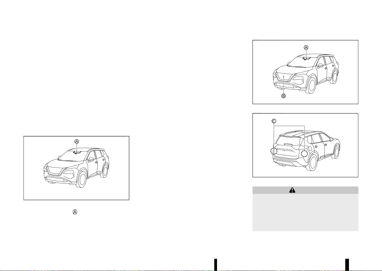
(286,1)
282 Starting and driving
SYSTEM MALFUNCTION
MEVT33A1-10570137-18EF-4700-A5A2-E522862D3216
If the Intelligent Lane Intervention system mal-
functions, it will cancel automatically. The Intelli-
gent Lane Intervention indicator (yellow) will
illuminates a chime will sound and the [System
fault See Owner’s Manual] warning message will
appear in the vehicle information display.
If the warning message appears, pull off the road
to a safe location. Turn the engine off and restart
the engine. If the warning message continues to
appear, have the Intelligent Lane Intervention
system checked. It is recommended that you visit
a NISSAN dealer or qualified workshop for this
service.
SYSTEM MAINTENANCE
MEVT33A1-B0E9F158-6B8C-4F76-9B9D-2994FA0A494A
MWAC0523X
The lane camera unit for the Intelligent Lane
Intervention system is located above the inside
rearview mirror. To keep the proper operation of
the Intelligent Lane Intervention system and pre-
vent a system malfunction, be sure to observe the
following:
* Always keep the windscreen clean.
* Do not attach a sticker (including transparent
material) or install an accessory near the
camera unit.
* Do not place reflective materials, such as white
paper or a mirror, on the instrument panel.
The reflection of sunlight may adversely affect
the camera unit’s capability of detecting the
lane markers.
* Do not strike or damage the areas around the
camera unit. Do not touch the camera lens or
remove the screw located on the camera unit.
If the camera unit is damaged due to an
accident, it is recommended that you visit a
NISSAN dealer or qualified workshop.
MEVT33A1-AC6C75D8-6D78-42A6-9627-6C40B6609A5D
MWAF0644X
MWAF1172X
WARNING
Failure to follow the warnings and instructions
for proper use of the ELA system could result in
serious injury or death.
* The ELA system will not steer the vehicle or
prevent loss of control. It is the driver’s
responsibility to stay alert, drive safely,
EMERGENCY LANE ASSIST (ELA)
SYSTEM (where fitted)
EMERGENCY LANE ASSIST (ELA)
SYSTEM (where fitted)
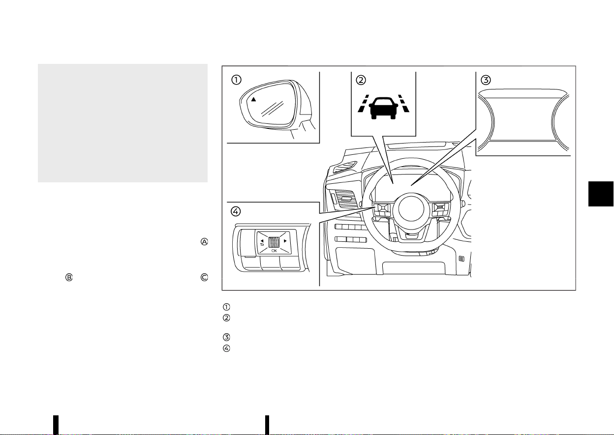
(287,1)
keep the vehicle in the travelling lane, and
be in control of the vehicle at all times.
* The ELA system is intended to work on all
roads with well defined markings or road
edges, but it may not detect the road edge
or lane markers in certain road, weather or
driving conditions.
* There is a limitation to the detection
capability of the radars and camera. Not
every moving object or vehicle will be
detected. Always rely on your own opera-
tion to avoid accidents.
The ELA system will be automatically turned on
each time the engine is restarted.
The sensitivity of the ELA system, can be adjusted
and this setting is kept until changed again by the
driver.
The ELA uses a multi-sensing front camera
located above the inside mirror to monitors the
lane markers on the travelling lane and to detect
other vehicles. The ELA system also uses radar
sensors
located at the front of the vehicle and
located near the rear bumpers to detect other
vehicles.
MWAF1173X
Side indicator light
ELA indicator (on the vehicle information
display)
Vehicle information display
Steering-wheel-mounted controls (left side)
ELA SYSTEM OPERATION
MEVT33A1-ABCAE77F-11BB-4EB1-983F-72A4D3DB4A01
The ELA system will operate when the vehicle is
driven at speeds of approximately 60 km/h (37
MPH) and above, and only when the lane markings
or road edge are clearly visible on the road.
The ELA system warns the driver when the vehicle
approaches the road edge or solid white line with
an indicator on the vehicle information display and
Starting and driving 283
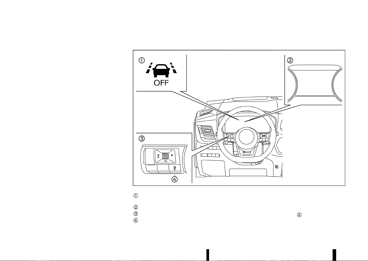
(288,1)
284 Starting and driving
steering wheel vibration. The system helps assist
the driver to return the vehicle to the carriage way
by applying the brakes to the left or right wheels
individually (for a short period of time) in the
following circumstances:
* The vehicle is approaching the edge of the
road, towards grass or gravel or a kerb, for
example.
* The vehicle is approaching a solid line on a
single lane marking.
* Oncoming vehicles in adjacent lanes.
* Overtaking vehicles in adjacent lanes. The side
indicator light will also flash.
* Intelligent Lane intervention can be turned on
to provide assistance in lanes on motorway/
dual carriage ways.
The strength of the steering wheel vibration can
be changed in the settings menu of the vehicle
information display. (See “[Driver Assistance]”
(P.83).)
HOW TO ENABLE/DISABLE THE ELA SYSTEM
MEVT33A1-150C194B-3128-42F0-AF80-6568A49E7134
MWAF1174X
ELA system OFF indicator (on the vehicle
information display)
Vehicle information display
Steering-wheel-mounted controls (left side)
Shortcut button
Perform either of the following steps to enable or
disable the ELA system.
Shortcut Menu
1. Push short cut button
on steering switch to
display [Shortcut Menu].

(289,1)
2. Select [Emergency Lane] and push the scroll
dial to turn the system on or off.
Settings
1. Push the
button until [Settings]
appears in the vehicle information display
and then push the scroll dial. Use the scroll
dial to select [Driver Assistance]. Then push the
scroll dial.
2. Select [Lane] and push the scroll dial.
3. Select [Emergency Lane] and push the scroll
dial to turn the system on or off.
When the ELA system is turned off, the ELA system
OFF indicator appears.
For details, see “Vehicle information display” (P.81).
NOTE:
* The ELA system will be automatically turned
on each time the engine is restarted.
* The Intelligent Lane Intervention is an addi-
tional aid that can be turned on in addition
to ELA system if required. For details, see
“Intelligent Lane Intervention (where fitted)”
(P.277).
Setting lane sensitivity
MEVT33A1-1777D738-200C-48F0-B645-E76FF5FF11E5
You can set lane sensitivity using the [Settings]
menu in the vehicle information display.
1. Push the
button until [Settings]
appears in the vehicle information display
and then push the scroll dial. Use the scroll
dial to select [Driver Assistance]. Then push the
scroll dial.
2. Select [Lane] and push the scroll dial.
3. Select [Lane Sensitivity].
.
[Strong]
.
[Normal]
.
[Mild]
NOTE:
The sensitivity setting will be retained even if the
engine is restarted. This setting is also applied to
the Lane Departure Warning (LDW) and Intelli-
gent Lane Intervention systems.
Even if the ELA system is disabled in the
[Settings] menu, the ELA system will automati-
cally be turned on when the Intelligent Lane
Intervention system is active.
ELA SYSTEM LIMITATIONS
MEVT33A1-E738F4DB-4FCF-4E49-BACD-CBE087194FE9
WARNING
Listed below are the system limitations for the
ELA system. Failure to operate the vehicle in
accordance with these system limitations
could result in serious injury or death.
* The ELA system may activate if you cross a
solid lane marker without first activating
your turn signal or, for example, if a
construction zone directs traffic to cross
an existing lane marker. If this occurs you
may need to apply corrective steering to
complete your lane change.
* Because the ELA may not activate under
the road, weather and lane marker condi-
tions described in this section, it may not
activate every time your vehicle begins to
leave the travelling lane and you will need
to apply corrective steering.
* The ELA system will not operate at speeds
below approximately 60 km/h (37 MPH) or
if it cannot detect lane markers.
* When the ELA system detects oncoming
vehicles in adjacent lanes, the ELA system
will not operate at speeds above approxi-
mately 120 km/h (74 MPH).
* DO NOT use the ELA system under the
following conditions, there could be ser-
ious affect on vehicle safety with risk of an
accident and injury or death.
— When driving without normal tyre
conditions (for example, tyre wear,
low tyre pressure, tyre chains, non-
standard wheels). See “Tyres and
Wheels” (P.448).
— When the vehicle is equipped with
non-original brake parts or suspen-
sion parts.
— When towing a trailer or another ve-
hicle.
* The ELA system may not function properly
in the following conditions
— During bad weather (rain, fog, snow,
etc.).
— When driving on slippery roads, such
as on ice or snow.
— When driving on winding or uneven
roads.
Starting and driving 285

(290,1)
286 Starting and driving
— When there is a lane closure due to
road repairs.
— When driving in a makeshift or tem-
porary lane.
— When driving on roads where the lane
width is too narrow.
— On roads where there are multiple
parallel lane markers; lane markers
that are faded or not painted clearly;
yellow painted lane markers; non-
standard lane markers; or lane mar-
kers covered with water, dirt, snow,
etc.
— On roads where the edge of the road is
not clearly visible.
— On roads where discontinued lane
markers are still detectable.
— On roads where there are sharp
curves.
— On roads where there are sharply
contrasting objects, such as shadows,
snow, water, wheel ruts, seams or lines
remaining after road repairs. (The ELA
system could detect these items as
lane markers.)
— On roads where the travelling lane
merges or separates.
— When the vehicle’s travelling direction
does not align with the lane marker.
— When travelling close to the vehicle in
front of you, which obstructs the lane
camera unit detection range.
— When rain, snow, dirt or object adheres
to the windscreen in front of the lane
camera unit.
— When the headlights are not bright
due to dirt on the lens or if the aiming
is not adjusted properly.
— When strong light enters the lane
camera unit. (For example, the light
directly shines on the front of the
vehicle at sunrise or sunset.)
— When a sudden change in brightness
occurs. (For example,when the vehicle
enters or exits a tunnel or under a
bridge.)
Listed below are the system limitations for the
overtaking detection feature of the ELA sys-
tem. Failure to operate the vehicle in accor-
dance with these system limitations could
result in serious injury or death.
* The ELA system cannot detect all over-
taking vehicles under all conditions.
* The radar sensors may not be able to
detect and activate ELA when certain
objects are present such as:
— Pedestrians, bicycles, animals.
— Vehicles such as motorcycles, low
height vehicles, or vehicles with high
ground clearance.
— Vehicles remaining in the detection
zone when you accelerate from a stop.
— A vehicle merging into an adjacent
lane at a speed approximately the
same as your vehicle.
— A vehicle approaching rapidly from
behind.
— A vehicle which your vehicle overtakes
rapidly.
— A vehicle that passes through the
detection zone quickly.
* The radar sensor’s detection zone is de-
signed based on a standard lane width.
When driving in a wider lane, the radar
sensors may not detect vehicles in an
adjacent lane. When driving in a narrow
lane, the radar sensors may detect vehicles
driving two lanes away.
* The radar sensors are designed to ignore
most stationary objects, however objects
such as guardrails, walls, foliage and
parked vehicles may occasionally be de-
tected. This is a normal operation condi-
tion.
* The following conditions may reduce the
ability of the radar to detect other vehicles:
— Severe weather
— Road spray
— Ice/frost/dirt build-up on the vehicle
* Do not attach stickers (including transpar-
ent material), install accessories or apply
additional paint near the radar sensors.
These conditions may reduce the ability of
the radar to detect other vehicles.
Listed below are the system limitations for the

(291,1)
Oncoming detection feature of the ELA system.
Failure to operate the vehicle in accordance
with these system limitations could result in
serious injury or death.
* The ELA system cannot detect all oncom-
ing vehicles under all conditions.
* The following are not detected as oncom-
ing vehicles:
— Pedestrians, bicycles, animals.
— Vehicles such as motorcycles, low
height vehicles, or vehicles with high
ground clearance.
— Parked Vehicles or Low speed Vehicles.
— Oncoming Vehicles on same lane.
* The ELA system may not function properly
or detect an oncoming vehicle in the
following conditions:
— In poor visibility conditions (such as
rain, snow, fog, dust storms, sand
storms, smoke and road spray from
other vehicles).
— If dirt, ice, snow, fog or other material
is covering the radar sensor area or
camera area of the windscreen.
— If strong light (for example, sunlight or
high beams) enters the front camera
or a sudden change in brightness
occurs (for example, entering a tunnel
or driving in lightning).
— In dark or dimly lit conditions, such as
at night or in tunnels, including cases
where your vehicle’s headlights are off
or dim, or the tail lights of the vehicle
ahead are off.
— When the direction of the camera is
misaligned.
— When driving on a steep downhill
slope, on roads with sharp curves,
and/or bumpy or dirt roads.
— If there is interference from other
radar sources.
— When your vehicle’s position or move-
ment is changed quickly or signifi-
cantly (for example, lane change,
turning vehicle, abrupt steering, sud-
den acceleration or deceleration).
— If the vehicle ahead has a unique or
unusual shape, extremely low or high
clearance heights, or unusual cargo
loading or is narrow (for example, a
motorcycle).
NOTE:
While the ELA system is operating, you may hear
a sound of brake operation. This is normal and
indicates that the ELA system is operating
properly.
SYSTEM TEMPORARILY UNAVAILABLE
MEVT33A1-35283744-A10A-4783-9912-826567EACFD9
Condition A:
The warning and assist functions of the ELA
system are not designed to work under the
following conditions:
* When you operate the lane change signal and
change the travelling lanes in the direction of
the signal. (The ELA system will be deactivated
for approximately 2 seconds after the lane
change signal is turned off). This does not
apply if an overtaking vehicle is detected.
* When the vehicle speed lowers to less than
approximately 60 km/h (37 MPH).
* When an oncoming vehicle is detected and the
vehicle speed is over approximately 120 km/h
(74 MPH).
After the above conditions have finished and the
necessary operating conditions are satisfied, the
warning and assist functions will resume.
Condition B:
The assist function of the ELA system is not
designed to work under the following conditions
(warning is still functional):
* When the brake pedal is depressed.
* When the steering wheel is turned as far as
necessary for the vehicle to change lanes.
* When the vehicle is accelerated during the ELA
system operation.
* When the Intelligent Cruise Control (ICC) ap-
proach warning occurs (where fitted).
* When the hazard warning flashers are oper-
ated.
* When driving on a curve at high speed.
After the above conditions have finished and the
necessary operating conditions are satisfied, the
ELA system application of the brakes will resume.
Condition C:
Starting and driving 287
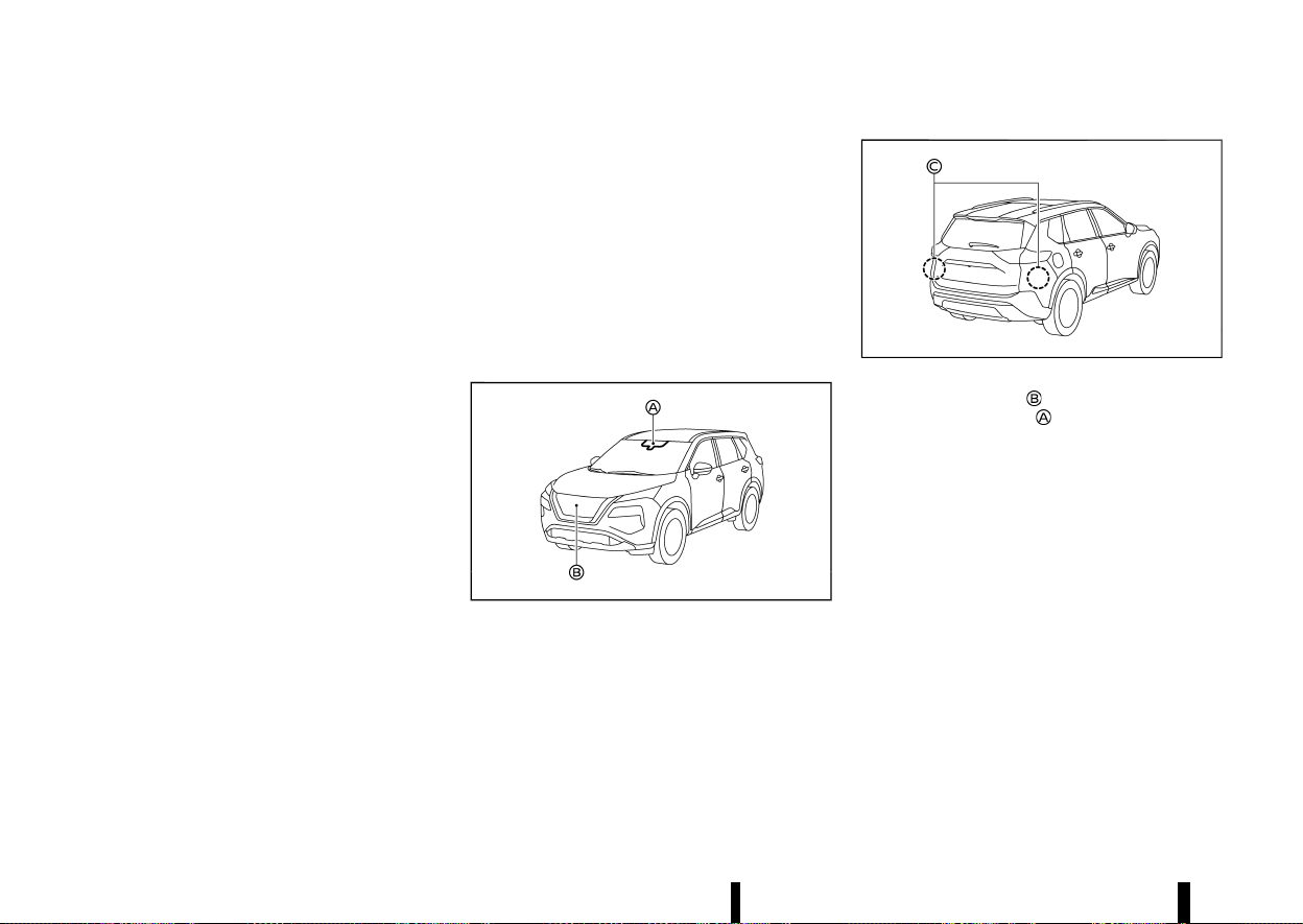
(292,1)
288 Starting and driving
If the VDC/ESP system is turned OFF, the ELA
system OFF indicator appears and the ELA system
will be turned off automatically.
When the VDC/ESP system turns ON again and the
necessary operating conditions are satisfied, the
ELA system application of the brakes will resume.
Condition D:
If one of the following messages appears in the
vehicle information display and the ELA indicator
blinks in the vehicle information display, the ELA
system will be turned off automatically:
* [Not available Side radar obstructed]: When the
rear radar is blocked. Always keep the area
near the radar sensors clean.
* [Temporarily Disabled Front Radar Blocked]:
When the front radar is blocked. Always keep
the area near the radar sensors clean.
* [Unavailable Low Visibility]: When the front
camera is blocked. Always keep the area near
the front camera clean.
* If the vehicle is parked in direct sunlight under
high temperature conditions (over approxi-
mately 40°C (104°F)) and then the ELA system
is turned on, the ELA system may be deacti-
vated automatically and the ELA indicator
blinks.
SYSTEM MALFUNCTION
MEVT33A1-F0D30AE2-5AC0-4EB6-9EBC-51801A8E226D
When the ELA system malfunctions, it will cancel
automatically. The ELA indicator (yellow) will ap-
pear, a chime will sound and the [System Fault See
Owner’s Manual] message will appear in the
vehicle information display. If the warning mes-
sage appears pull off the road in a safe location,
turn off and restart the engine. If the message
continues to appear, have the ELA system checked
by a NISSAN dealer or qualified workshop.
SYSTEM MAINTENANCE
MEVT33A1-AC2C4364-40A8-473B-B1A8-2332561A61A5
MWAF0644X
MWAF1172X
The front radar sensor is located on the front of
the vehicle. The camera
is located on the upper
side of the windscreen. To keep the ELA system
operating properly, be sure to observe the follow-
ing:
* Always keep the sensor area on the front of
the vehicle and windscreen clean.
* Do not strike or damage the areas around the
sensors (bumper, windscreen).
* Do not cover or attach stickers or similar
objects on the front of the vehicle near the
sensor area. This could cause failure or mal-
function.
* Do not attach metallic objects near the radar
sensor area (brush guard, etc.). This could
cause failure or malfunction.
* Do not place reflective materials, such as white
paper or a mirror, on the instrument panel.
The reflection of sunlight may adversely affect
the camera unit’s detection capability.
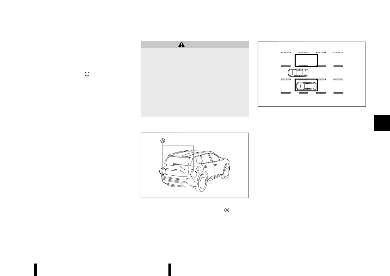
(293,1)
* Do not alter, remove or paint the front of the
vehicle near the sensor area. Before customis-
ing or restoring the sensor area, it is recom-
mended that you visit a NISSAN dealer or
qualified workshop.
The two rear radar sensors
for the ELA system
are located near the rear bumper. Always keep the
area near the radar sensors clean.
The radar sensors may be blocked by temporary
ambient conditions such as splashing water, mist
or fog. The blocked condition may also be caused
by objects such as ice, frost or dirt obstructing the
radar sensors.
Check for and remove objects obstructing the area
around the radar sensors.
Do not attach stickers (including transparent
material), install accessories or apply additional
paint near the radar sensors.
Do not strike or damage the area around the radar
sensors.
It is recommended you visit a NISSAN dealer or
qualified workshop if the area around the radar
sensors is damaged due to a collision.
MEVT33A1-7B5227BA-C06F-4E32-BCB6-05C9409131DC
WARNING
Failure to follow the warnings and instructions
for proper use of the BSW system could result
in serious injury or death.
* The BSW system is not a replacement for
proper driving procedure and is not de-
signed to prevent contact with vehicles or
objects. When changing lanes, always use
the side and rear mirrors and turn and look
in the direction your vehicle will move to
ensure it is safe to change lanes. Never rely
solely on the BSW system.
The BSW system helps alert the driver of other
vehicles in adjacent lanes when changing lanes.
MWAF0414X
The BSW system uses radar sensors installed
near the rear bumper to detect other vehicles in an
adjacent lane.
MSSD1030
Detection zone
The radar sensors can detect vehicles on either
side of your vehicle within the detection zone
shown as illustrated. This detection zone starts
from the outside rearview mirror of your vehicle
and extends approximately 3.0 m (10 ft) behind the
rear bumper, and approximately 3.0 m (10 ft)
sideways.
Starting and driving 289
BLIND SPOT WARNING (BSW) (where fitted)
BLIND SPOT WARNING (BSW) (where fitted)
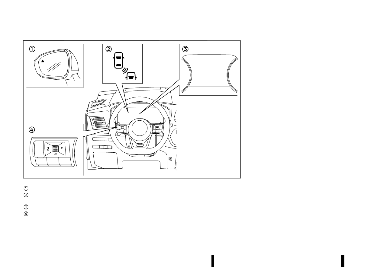
(294,1)
290 Starting and driving
MWAF0413X
Side indicator light
BSW indicator (on the vehicle information
display)
Vehicle information display
Steering-wheel-mounted controls (left side)
BSW SYSTEM OPERATION
MEVT33A1-0D8B8B8E-5970-42BA-AFAF-C53118AD6798
The BSW system operates above approximately 32
km/h (20 MPH).
If the radar sensors detect a vehicle in the
detection zone, the side indicator light illuminates.
If the turn signal is then activated, the system
chimes (twice) and the side indicator light and BSW
indicator flash. The side indicator light and BSW
indicator continue to flash until the detected
vehicle leaves the detection zone.
The side indicator light illuminates for a few
seconds when the ignition switch is placed in the
ON position.
The brightness of the side indicator light is
adjusted automatically depending on the bright-
ness of the ambient light.
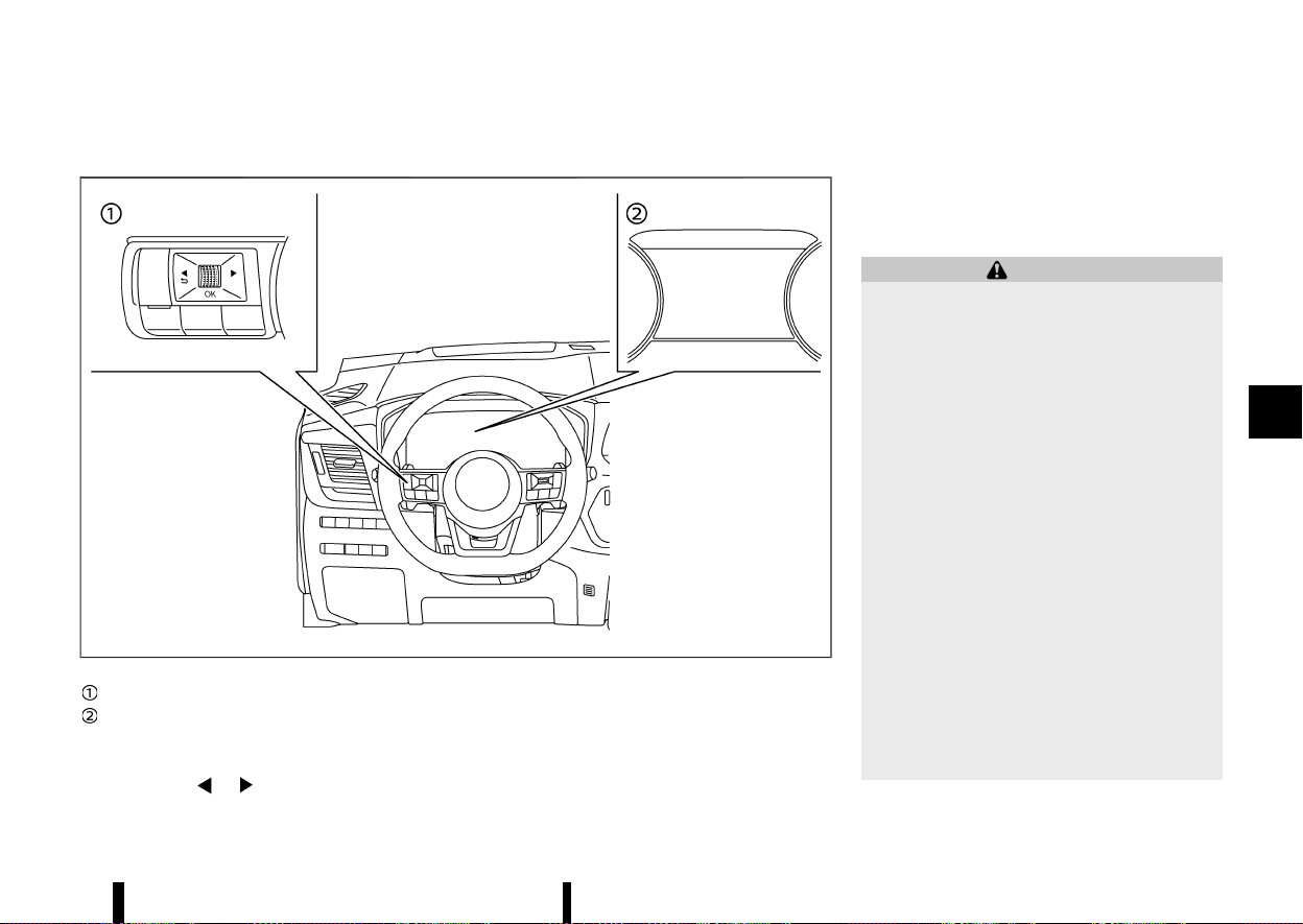
(295,1)
HOW TO ENABLE/DISABLE THE BSW SYSTEM
MEVT33A1-55487D1B-D8B7-4E42-B76F-42B9A63601B1
MWAF0412X
Steering-wheel-mounted controls (left side)
Vehicle information display
Perform the following steps to enable or disable
the BSW system.
1. Push the
button until [Settings]
appears in the vehicle information display
and then push the scroll dial. Use the scroll
dial to select [Driver Assistance]. Then push the
scroll dial.
2. Select [Blind Spot] and push the scroll dial.
3. Select [Warning] and push the scroll dial.
NOTE:
The system will retain current settings in the
vehicle information display even if the engine is
restarted.
BSW SYSTEM LIMITATIONS
MEVT33A1-5165A6ED-1AD0-460A-B0FC-34DE83FF8C9B
WARNING
Listed below are the system limitations for the
BSW system. Failure to operate the vehicle in
accordance with these system limitations
could result in serious injury or death.
* The BSW system cannot detect all vehicles
under all conditions.
* The radar sensors may not be able to
detect and activate BSW when certain
objects are present such as:
— Pedestrians, bicycles, animals.
— Vehicles such as motorcycles, low
height vehicles, or high ground clear-
ance vehicles.
— Oncoming vehicles.
— Vehicles remaining in the detection
zone when you accelerate from a stop.
— A vehicle merging into an adjacent
lane at a speed approximately the
same as your vehicle.
— A vehicle approaching rapidly from
behind.
— A vehicle which your vehicle overtakes
rapidly.
Starting and driving 291
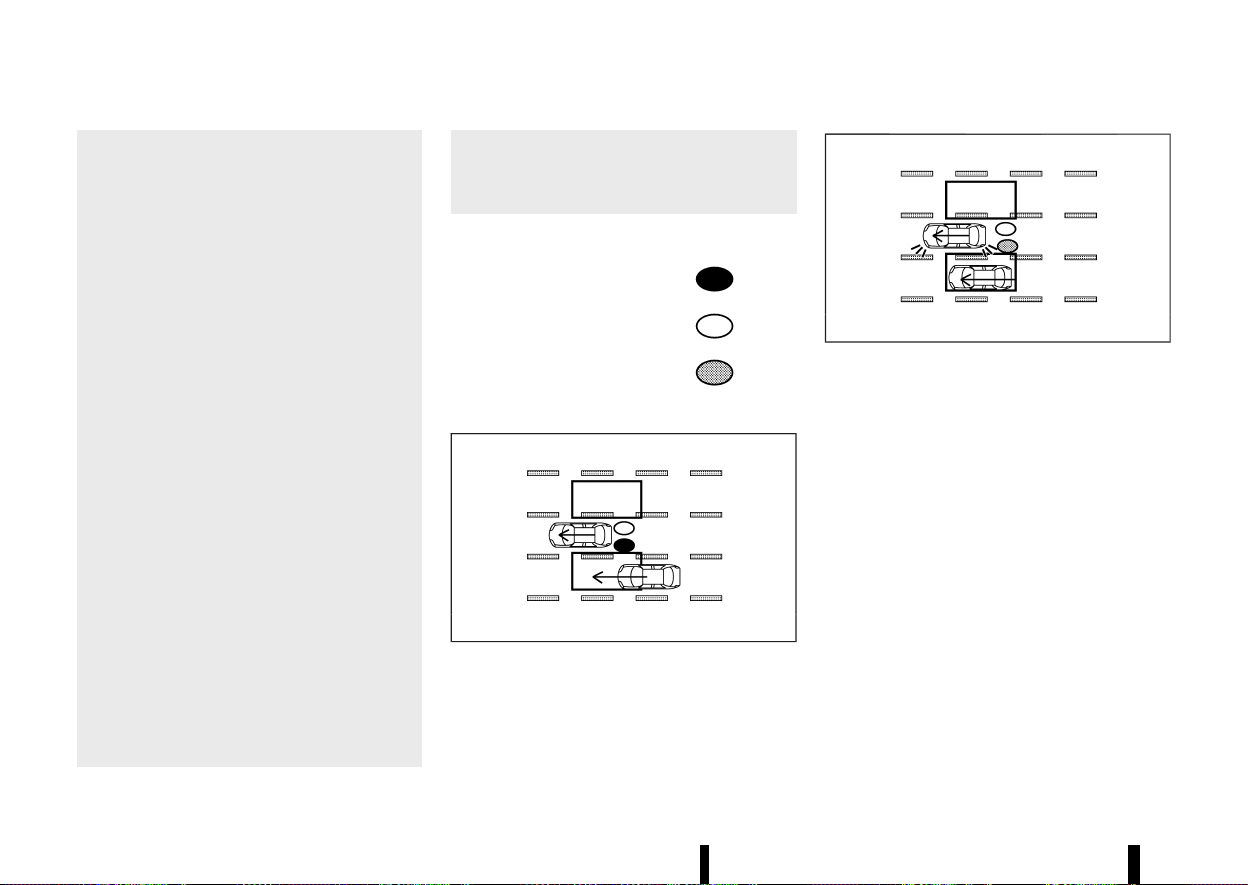
(296,1)
292 Starting and driving
— A vehicle that passes through the
detection zone quickly.
— When overtaking several vehicles in a
row, the vehicles after the first vehicle
may not be detected if they are travel-
ling close together.
* The radar sensor’s detection zone is de-
signed based on a standard lane width.
When driving in a wider lane, the radar
sensors may not detect vehicles in an
adjacent lane. When driving in a narrow
lane, the radar sensors may detect vehicles
driving two lanes away.
* The radar sensors are designed to ignore
most stationary objects, however objects
such as guardrails, walls, foliage and
parked vehicles may occasionally be de-
tected. This is a normal operation condi-
tion.
* The following conditions may reduce the
ability of the radar to detect other vehicles:
— Severe weather
— Road spray
— Ice/frost/dirt build-up on the vehicle
* Do not attach stickers (including transpar-
ent material), install accessories or apply
additional paint near the radar sensors.
These conditions may reduce the ability of
the radar to detect other vehicles.
* Do not use the BSW system when towing a
trailer or other vehicle. The system may
not function properly.
* Excessive noise (for example, audio system
volume, open vehicle window) will interfere
with the chime sound, and it may not be
heard.
BSW DRIVING SITUATIONS
MEVT33A1-6271EF97-8A54-4790-BB31-31DB9928FFF9
Indicator on
Indicator off
Indicator flashing
Another vehicle approaching from behind
MEVT33A1-E3566D25-0BAA-400E-A4BF-D6DD5477F8EC
MJVS0737X
Illustration 1 – Approaching from behind
Illustration 1: The side indicator light illuminates if a
vehicle enters the detection zone from behind in
an adjacent lane.
MJVS0738X
Illustration 2 – Approaching from behind
Illustration 2: If the driver activates the turn signal
while another vehicle is in the detection zone, then
the system chimes (twice) and the side indicator
light and BSW indicator flash.
NOTE:
The radar sensors may not detect vehicles which
are approaching rapidly from behind.
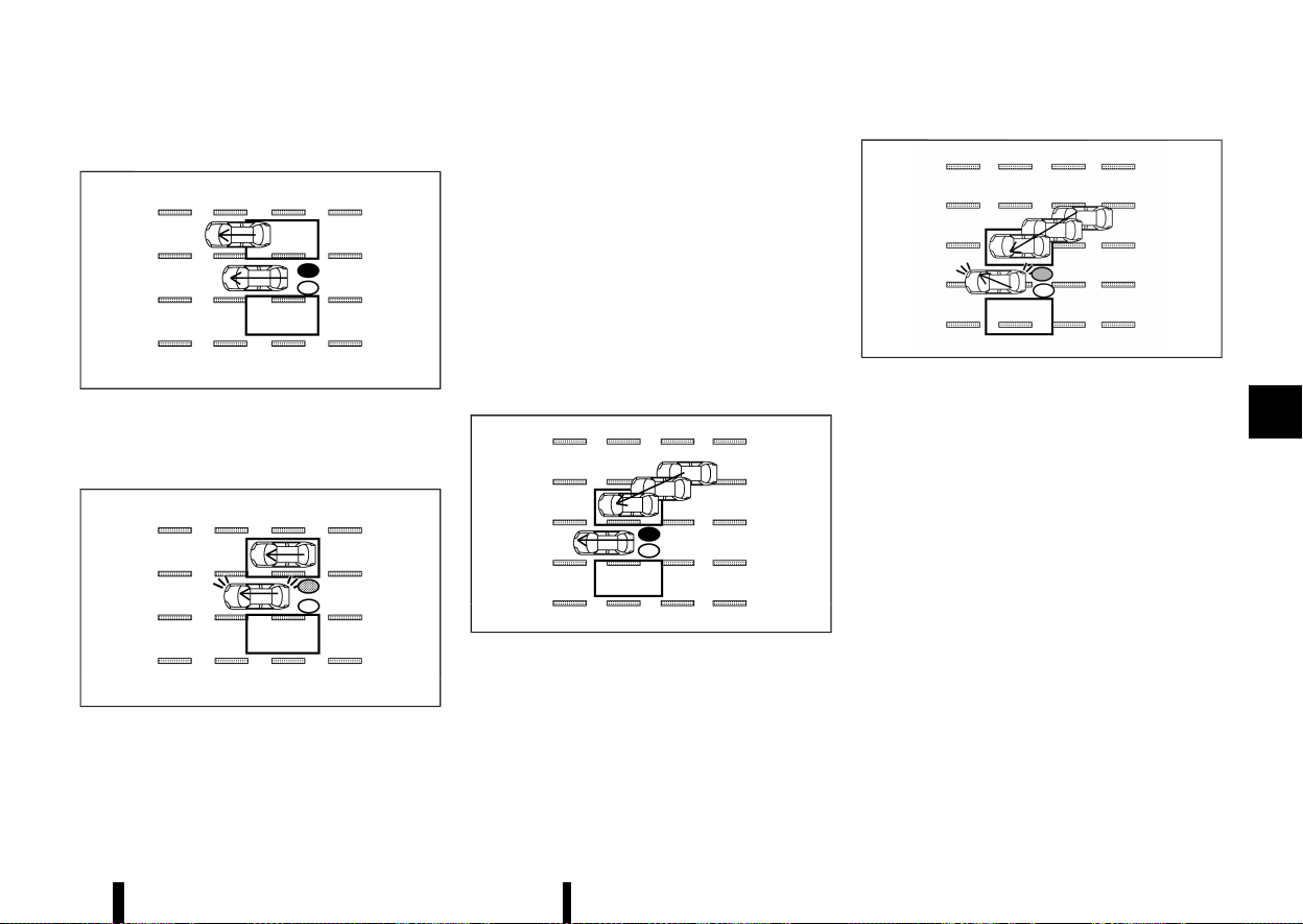
(297,1)
Overtaking another vehicle
MEVT33A1-4FD23A11-BF26-4AEB-8893-6D35AFFFE066
MJVS0739X
Illustration 3 – Overtaking another vehicle
Illustration 3: The side indicator light illuminates if
you overtake a vehicle and that vehicle stays in the
detection zone for approximately 2 seconds.
MJVS0740X
Illustration 4 – Overtaking another vehicle
Illustration 4: If the driver activates the turn signal
while another vehicle is in the detection zone, then
the system chimes (twice) and the side indicator
light and BSW indicator flash.
NOTE:
* When overtaking several vehicles in a row,
the vehicles after the first vehicle may not be
detected if they are travelling close to-
gether.
* The radar sensors may not detect slower
moving vehicles if they are passed quickly.
* If the driver activates the turn signal before
a vehicle enters the detection zone, the side
indicator light and BSW indicator will flash
but no chime will sound when the other
vehicle is detected.
Entering from the side
MEVT33A1-17655A1C-15C3-419C-AC35-34185D610911
MJVS0741X
Illustration 5 – Entering from the side
Illustration 5: The side indicator light illuminates if a
vehicle enters the detection zone from either side.
MWAF0555X
Illustration 6 – Entering from the side
Illustration 6: If the driver activates the turn signal
while another vehicle is in the detection zone, then
the system chimes (twice) and the side indicator
light and BSW indicator flash.
NOTE:
* The radar sensors may not detect a vehicle
which is travelling at about the same speed
as your vehicle when it enters the detection
zone.
SYSTEM TEMPORARILY UNAVAILABLE
MEVT33A1-55061AE4-D96B-4916-A984-5C6E7F266237
When radar blockage is detected, the BSW system
will be turned off automatically and the [Not
available Side radar obstructed] warning message
will appear in the vehicle information display.
The system is not available until the conditions no
longer exist.
The radar sensors may be blocked by temporary
ambient conditions such as splashing water, mist
or fog. The blocked condition may also be caused
Starting and driving 293
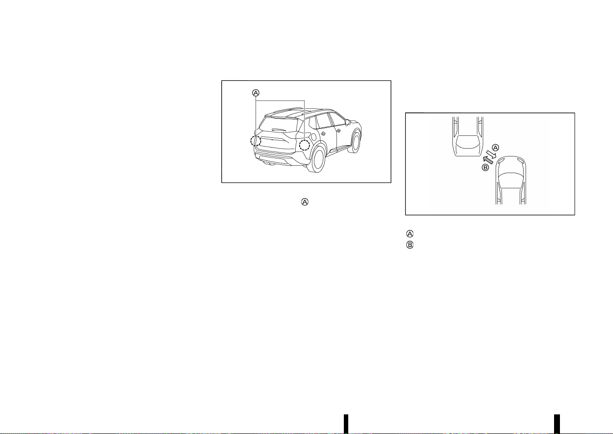
(298,1)
294 Starting and driving
by objects such as ice, frost or dirt obstructing the
radar sensors.
NOTE:
If the BSW system stops working, the Intelligent
Blind Spot Intervention (where fitted) and the
Rear Cross Traffic Alert (RCTA) system will also
stop working.
Action to take:
When the above conditions no longer exist, the
system will resume automatically.
SYSTEM MALFUNCTION
MEVT33A1-C18DA6A0-8908-429E-8D06-A908AABB4E6A
When the BSW system malfunctions, it will be
turned off automatically and the [System fault
See Owner’s Manual] warning message will appear
in the vehicle information display.
NOTE:
If the BSW system stops working, the Intelligent
Blind Spot Intervention (where fitted) and the
Rear Cross Traffic Alert (RCTA) system will also
stop working.
Action to take:
Stop the vehicle in a safe location, turn the engine
off and restart the engine. If the message con-
tinues to appear, have the BSW system checked. It
is recommended that you visit a NISSAN dealer or
qualified workshop for this service.
SYSTEM MAINTENANCE
MEVT33A1-88773295-5D23-4061-B514-F4F4D43D5869
MWAF0414X
The two radar sensors for the BSW system are
located near the rear bumper. Always keep the
area near the radar sensors clean.
The radar sensors may be blocked by temporary
ambient conditions such as splashing water, mist
or fog.
The blocked condition may also be caused by
objects such as ice, frost or dirt obstructing the
radar sensors.
Check for and remove objects obstructing the area
around the radar sensors.
Do not attach stickers (including transparent
material), install accessories or apply additional
paint near the radar sensors.
Do not strike or damage the area around the radar
sensors.
See a NISSAN dealer or qualified workshop or other
authorised repair shop if the area around the radar
sensors is damaged due to a collision.
Precautions on repairing the bumper
MEVT33A1-D69E46B2-3158-4366-8E2D-5EF12A8E7DDB
When repairing the bumper, take cautious because
the radar sensors are installed on the bumper.
Mechanism of the radar sensor:
MWBF0182X
Radar signal
Reflected signal
The radar sensor detects objects by emitting a
radar signal and then measuring its reflection.
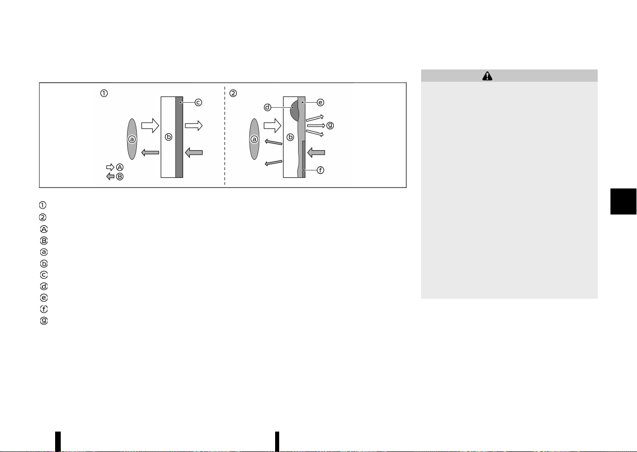
(299,1)
Repairing the bumper:
MWBF0183X
Normal condition (before the repair)
Poor condition (after the improper repair)
Radar signal
Reflected signal
Radar sensor
Vehicle bumper
Film layer
Putty
Touch-up layer
Repaint
Radar signal diffusion
If an improper repair is performed on the bumper
(for example, application of putty made from
different materials, repaint, etc.), the radar signal
could be weaken or prevented from functioning
properly. This may cause the radar sensor not to
detect objects correctly.
MEVT33A1-62DEE98D-667D-48CE-8A09-FA7D60BF5E72
WARNING
Failure to follow the warnings and instructions
for proper use of the Intelligent Blind Spot
Intervention system could result in serious
injury or death.
* The Intelligent Blind Spot Intervention
system is not a replacement for proper
driving procedures and is not designed to
prevent contact with vehicles or objects.
When changing lanes, always use the side
and rear mirrors and turn and look in the
direction your vehicle will move to ensure
it is safe to change lanes. Never rely solely
on the Intelligent Blind Spot Intervention
system.
* There is a limitation to the detection
capability of the radar. Not every moving
object or vehicle will be detected. Using the
Intelligent Blind Spot Intervention system
under some road, ground, lane marker,
traffic or weather conditions could lead to
improper system operation. Always rely on
your own operation to avoid accidents.
The Intelligent Blind Spot Intervention system
helps alert the driver of other vehicles in adjacent
lanes when changing lanes, and helps assist the
driver to return the vehicle to the centre of the
travelling lane.
Starting and driving 295
INTELLIGENT BLIND SPOT IN-
TERVENTION (where fitted)
INTELLIGENT BLIND SPOT IN-
TERVENTION (where fitted)
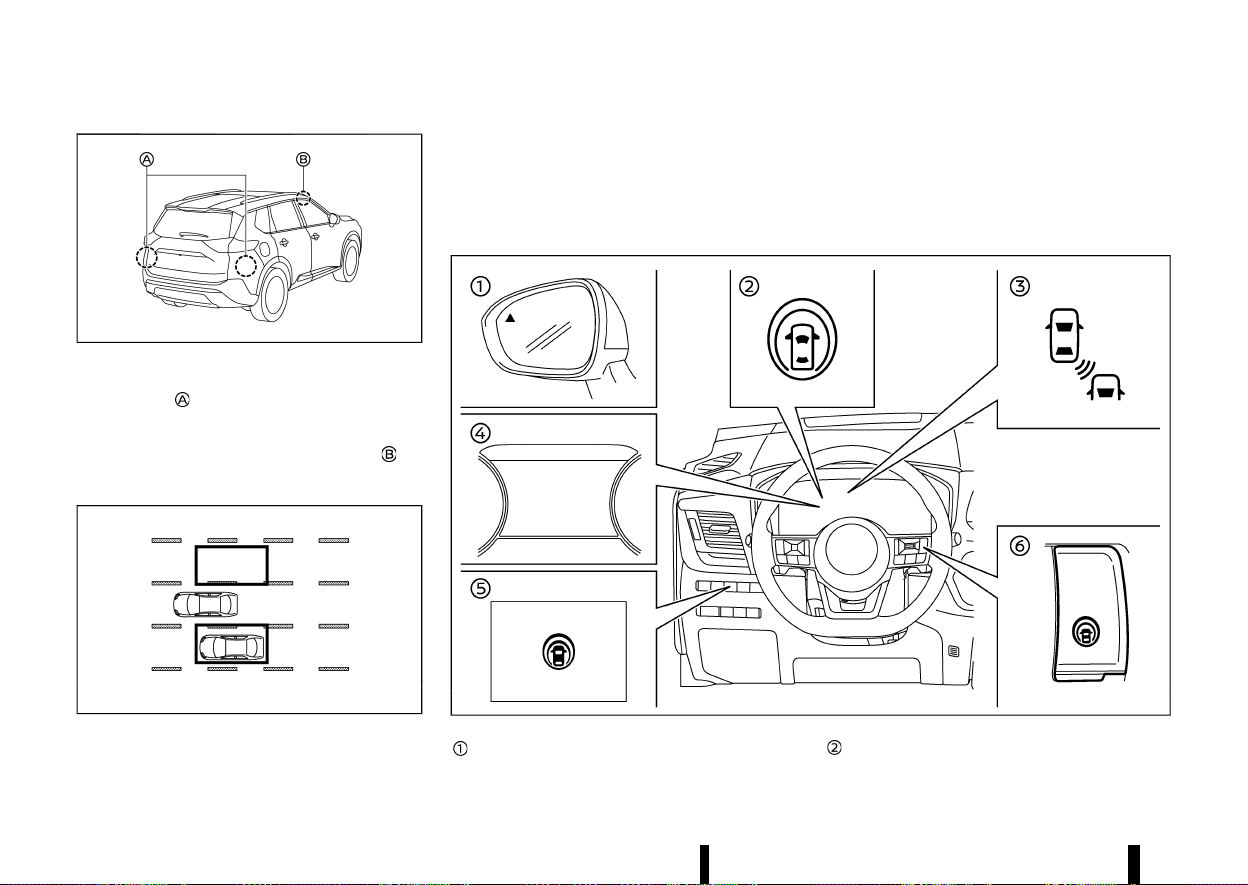
(300,1)
296 Starting and driving
MWAF0633X
The Intelligent Blind Spot Intervention system uses
radar sensors
installed near the rear bumper to
detect other vehicles in an adjacent lane. In
addition to the radar sensors, the Intelligent Blind
Spot Intervention system uses a camera
in-
stalled behind the windscreen to monitor the lane
markers of your travelling lane.
MSSD1030
Detection zone
The radar sensors can detect vehicles on either
side of your vehicle within the detection zone
shown as illustrated.
This detection zone starts from the outside mirror
of your vehicle and extends approximately 3.0 m
(10 ft) behind the rear bumper, and approximately
3.0 m (10 ft) sideways.
MWAF1176X
Side indicator light
Intelligent Blind Spot Intervention ON indica-
tor (on the vehicle information display)

(301,1)
Intelligent Blind Spot Intervention indicator
(on the vehicle information display)
Vehicle information display
Dynamic driver assistance switch (models
without ProPILOT Assist system)
ProPILOT Assist switch (models with ProPI-
LOT Assist system)
INTELLIGENT BLIND SPOT INTERVEN-
TION SYSTEM OPERATION
MEVT33A1-AFA6F3FD-D004-445D-8211-CC0913C5754E
The Intelligent Blind Spot Intervention system
operates above approximately 60 km/h (37 MPH).
If the radar sensors detect a vehicle in the
detection zone, the side indicator light illuminates.
If the turn signal is then activated, the system
chimes (twice) and the side indicator light and
Intelligent Blind Spot Intervention indicator flash.
The side indicator light and Intelligent Blind Spot
Intervention indicator continue to flash until the
detected vehicle leaves the detection zone.
If the Intelligent Blind Spot Intervention system is
ON and your vehicle approaches a lane marker
while another vehicle is in the detection zone, the
system chimes (three times) and the side indicator
light and Intelligent Blind Spot Intervention indi-
cator flash. The Intelligent Blind Spot Intervention
system activates by applying the brakes on one
side of the vehicle for a short period of time to help
return the vehicle back to the centre of the driving
lane. The Intelligent Blind Spot Intervention system
operates regardless of turn signal usage.
To turn on the Intelligent Blind Spot Intervention
system, push the ProPILOT Assist switch on the
steering wheel (where fitted) or the dynamic driver
assistance switch on the driver’s side instrument
panel (where fitted) after starting the engine. The
Intelligent Blind Spot Intervention ON indicator on
the vehicle information display will illuminate. Push
the ProPILOT Assist switch (where fitted) or the
dynamic driver assistance switch (where fitted)
again to turn off the Intelligent Blind Spot Inter-
vention system.
NOTE:
* Intelligent Blind Spot Intervention warning
and system application will only be acti-
vated if the side indicator light is already
illuminated when your vehicle approaches a
lane marker. If another vehicle comes into
the detection zone after your vehicle has
crossed a lane marker, no Intelligent Blind
Spot Intervention warning or system appli-
cation will be activated. (For additional
information, see “Intelligent Blind Spot In-
tervention driving situations” (P.300).)
* The Intelligent Blind Spot Intervention sys-
tem is typically activated earlier than the
Intelligent Lane Intervention system when
your vehicle is approaching a lane marker.
Starting and driving 297
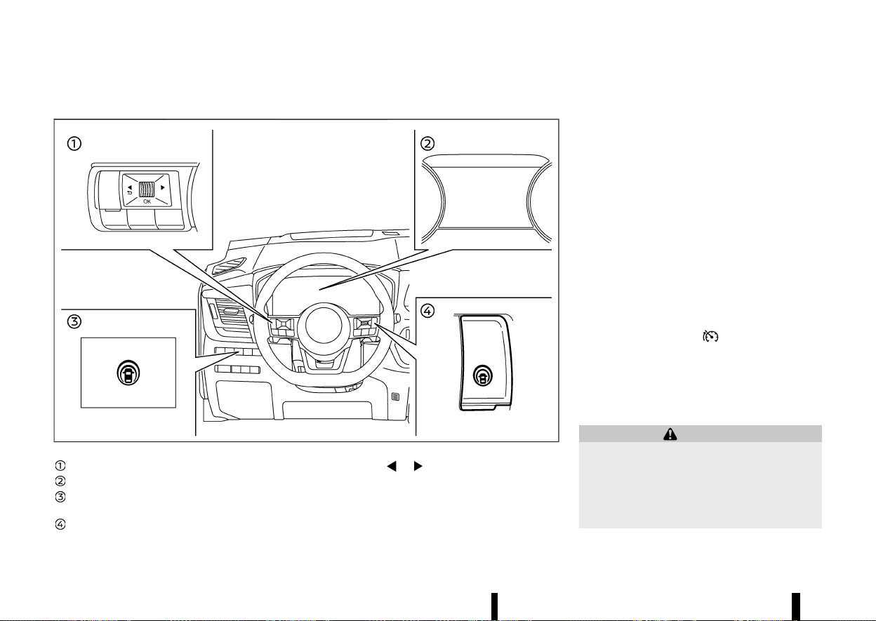
(302,1)
298 Starting and driving
HOW TO ENABLE/DISABLE THE INTELLIGENT BLIND SPOT INTERVENTION SYSTEM
MEVT33A1-6943C389-7440-4386-9D46-CC63460BE44A
MWAF1177X
Steering-wheel-mounted control (left side)
Vehicle information display
Dynamic driver assistance switch (models
without ProPILOT Assist system)
ProPILOT Assist switch (models with ProPI-
LOT Assist system)
1. Push the
button until [Settings] ap-
pears in the vehicle information display and
then push the scroll dial. Use the scroll dial to
select [Driver Assistance]. Then push the scroll
dial.
2. Select [Blind Spot] and push the scroll dial.
3. Select [Intervention] and push the scroll dial.
4. Push the ProPILOT Assist switch (where fitted)
or the dynamic driver assistance switch
(where fitted) to turn the system on or off.
NOTE:
* Turning on the ProPILOT Assist system
(where fitted) will turn on the Intelligent
Blind Spot Intervention and Intelligent Lane
Intervention systems at the same time. For
additional information, see “Intelligent Lane
Intervention (where fitted)” (P.277).
* For model with ProPILOT Assist system:
When the Intelligent Blind Spot Intervention
system is enabled in the settings menu, the
Intelligent Blind Spot Intervention system
can be turned on or off by pushing the speed
limiter MAIN switch
(where fitted).
* Turning the BSW system off will deactivate
the Intelligent Blind Spot Intervention sys-
tem at the same time.
INTELLIGENT BLIND SPOT INTERVEN-
TION SYSTEM LIMITATIONS
MEVT33A1-768C7C37-A993-4205-9B13-6EF54DB3DAF9
WARNING
Listed below are the system limitations for the
Intelligent Blind Spot Intervention system.
Failure to operate the vehicle in accordance
with these system limitations could result in
serious injury or death.
* The Intelligent Blind Spot Intervention

(303,1)
system cannot detect all vehicles under all
conditions.
* The radar sensors may not be able to
detect and activate the Intelligent Blind
Spot Intervention when certain objects are
present such as:
— Pedestrians, bicycles, animals.
— Vehicles such as motorcycles, low
height vehicles, or high ground clear-
ance vehicles.
— Vehicles remaining in the detection
zone when you accelerate from a stop.
— Oncoming vehicles.
— A vehicle merging into an adjacent
lane at a speed approximately the
same as your vehicle.
— A vehicle approaching rapidly from
behind.
— A vehicle which your vehicle overtakes
rapidly.
— A vehicle that passes through the
detection zone quickly.
* The radar sensor’s detection zone is de-
signed based on a standard lane width.
When driving in a wider lane, the radar
sensors may not detect vehicles in an
adjacent lane. When driving in a narrow
lane, the radar sensors may detect vehicles
driving two lanes away.
* The radar sensors are designed to ignore
most stationary objects, however objects
such as guardrails, walls, foliage and
parked vehicles may occasionally be de-
tected. This is a normal operation condi-
tion.
* The following conditions may reduce the
ability of the radar to detect other vehicles:
— Severe weather
— Road spray
— Ice/frost/dirt build-up on the vehicle
* Do not attach stickers (including transpar-
ent material), install accessories or apply
additional paint near the radar sensors.
These conditions may reduce the ability of
the radar to detect other vehicles.
* The camera may not detect lane markers
in the following situations and the Intelli-
gent Blind Spot Intervention system may
not operate properly.
— On roads where there are multiple
parallel lane markers; lane markers
that are faded or not painted clearly;
yellow painted lane markers; nonstan-
dard lane markers; lane markers cov-
ered with water, dirt, snow, etc.
— On roads where discontinued lane
markers are still detectable.
— On roads where there are sharp
curves.
— On roads where there are sharply
contrasting objects, such as shadows,
snow, water, wheel ruts, seams or lines
remaining after road repairs.
— On roads where the travelling lane
merges or separates.
— When the vehicle’s travelling direction
does not align with the lane markers.
— When travelling close to the vehicle in
front of you, which obstructs the lane
camera unit detection range.
— When rain, snow or dirt adheres to the
windscreen in front of a lane camera
unit.
— When the headlights are not bright
due to dirt on the lens or if aiming is
not adjusted properly.
— When strong light enters a lane cam-
era unit. (For example: light directly
shines on the front of the vehicle at
sunrise or sunset.)
— When a sudden change in brightness
occurs. (For example: when the vehicle
enters or exits a tunnel or under a
bridge.)
* Do not use the Intelligent Blind Spot Inter-
vention system under the following condi-
tions because the system may not function
properly.
— During bad weather. (For example:
rain, fog, snow, etc.)
— When driving on slippery roads, such
as on ice or snow, etc.
— When driving on winding or uneven
roads.
Starting and driving 299
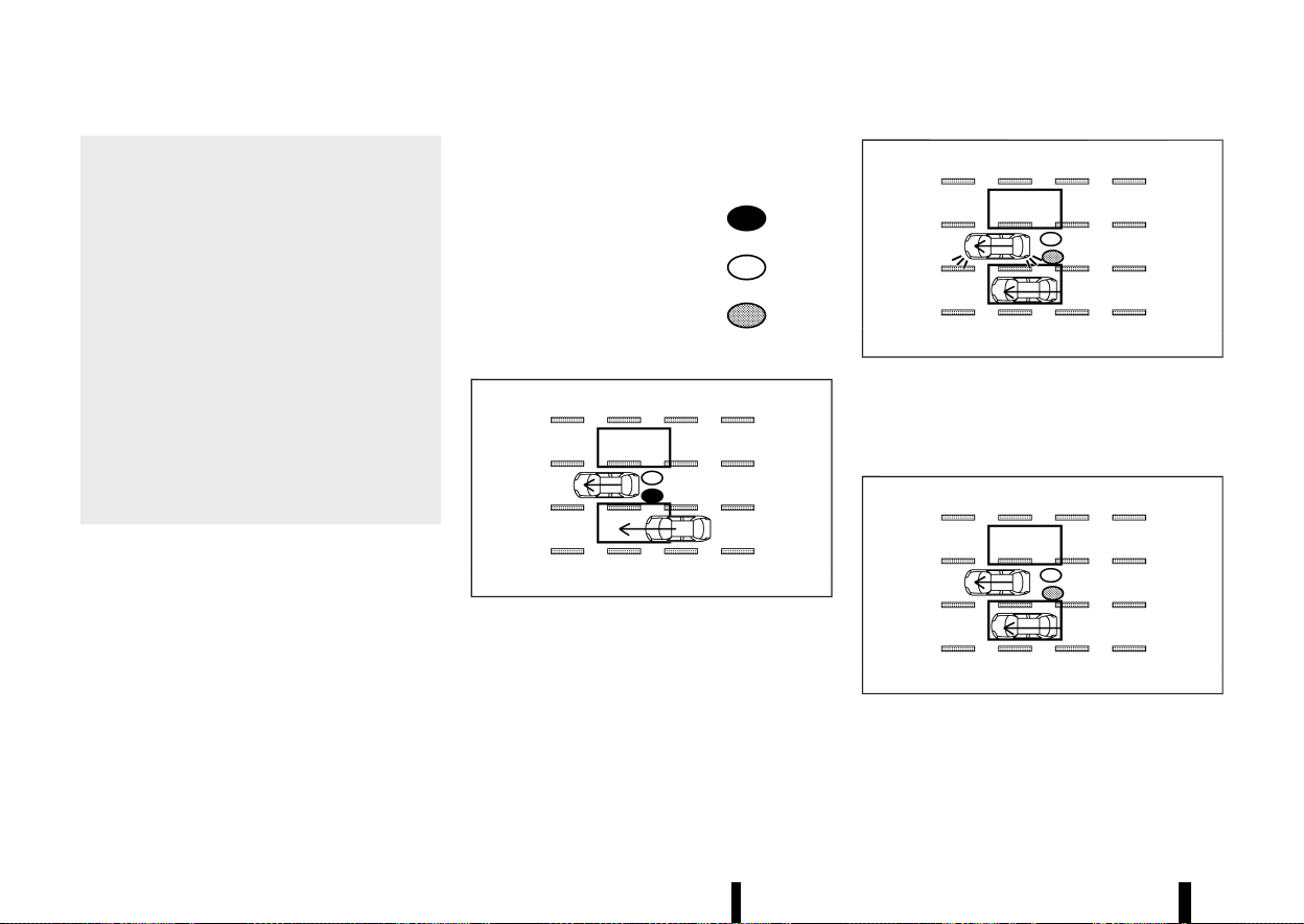
(304,1)
300 Starting and driving
— When there is a lane closure due to
road repairs.
— When driving in a makeshift or tem-
porary lane.
— When driving on roads where the lane
width is too narrow.
— When driving with a tyre that is not
within normal tyre conditions (for ex-
ample, tyre wear, low tyre pressure,
tyre chains, non-standard wheels).
— When the vehicle is equipped with
non-original brake parts or suspen-
sion parts.
— When towing a trailer or other vehicle.
* Excessive noise (for example, audio system
volume, open vehicle window) will interfere
with the chime sound, and it may not be
heard.
INTELLIGENT BLIND SPOT INTERVEN-
TION DRIVING SITUATIONS
MEVT33A1-F2F9AB47-9574-4FB0-9080-13F711855C65
Indicator on
Indicator off
Indicator flashing
Another vehicle approaching from behind
MEVT33A1-9AAA85B2-77C3-4FC4-B0B2-E7D88FA81EA5
MJVS0737X
Illustration 1 – Approaching from behind
Illustration 1: The side indicator light illuminates if a
vehicle enters the detection zone from behind in
an adjacent lane.
MJVS0738X
Illustration 2 – Approaching from behind
Illustration 2: If the driver activates the turn signal
then the system chimes a sound (twice) and the
side indicator light and Intelligent Blind Spot
Intervention indicator flash.
MJVS0760X
Illustration 3 - Approaching from behind
Illustration 3: If the Intelligent Blind Spot Interven-
tion system is on and your vehicle approaches a
lane marker while another vehicle is in the detec-
tion zone, the system chimes (three times) and the
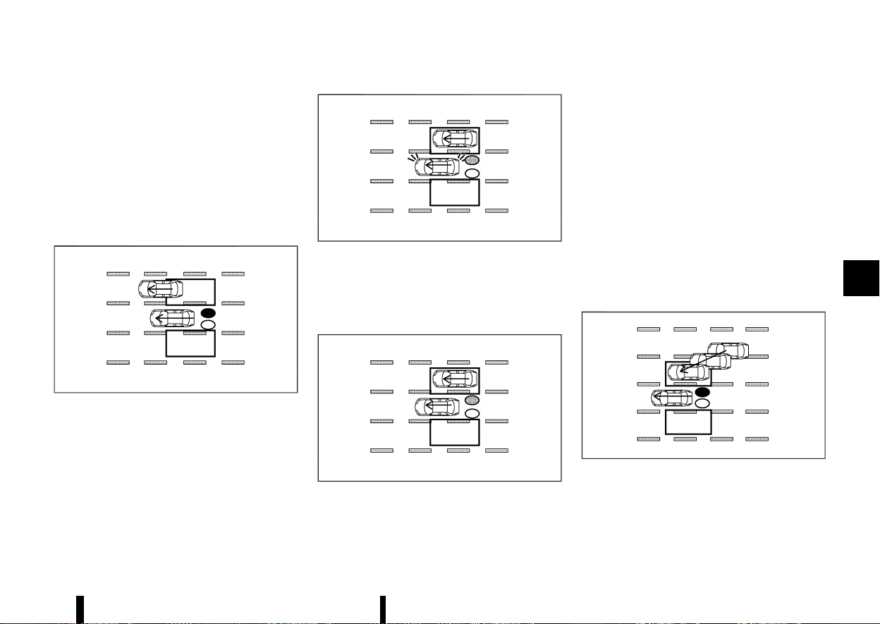
(305,1)
side indicator light and Intelligent Blind Spot
Intervention indicator flash. The Intelligent Blind
Spot Intervention system activates by applying the
brakes on one side of the vehicle for a short period
of time to help return the vehicle back to the
centre of the driving lane.
NOTE:
The radar sensors may not detect vehicles which
are approaching rapidly from behind.
Overtaking another vehicle
MEVT33A1-33E692F3-285E-4FAF-A1B1-8BAD421093F1
MJVS0739X
Illustration 4 - Overtaking another vehicle
Illustration 4: The side indicator light illuminates if
you overtake a vehicle and that vehicle stays in the
detection zone for approximately 3 seconds.
MJVS0740X
Illustration 5 - Overtaking another vehicle
Illustration 5: If the driver activates the turn signal
while another vehicle is in the detection zone, then
the system chimes (twice) and the side indicator
light and Intelligent Blind Spot Intervention indi-
cator flash.
MJVS0761X
Illustration 6 - Overtaking another vehicle
Illustration 6: If the Intelligent Blind Spot Interven-
tion system is on and your vehicle approaches a
lane marker while another vehicle is in the detec-
tion zone, the system chimes (three times) and the
side indicator light and Intelligent Blind Spot
Intervention indicator flash. The Intelligent Blind
Spot Intervention system activates to by applying
the brakes on one side of the vehicle for a short
period of time to help return the vehicle back to
the centre of the driving lane.
NOTE:
* When overtaking several vehicles in a row,
the vehicles after the first vehicle may not be
detected if they are travelling close to-
gether.
* The radar sensors may not detect slower
moving vehicles if they are passed quickly.
Entering from the side
MEVT33A1-1C822A1D-100F-44CC-89B6-4C39016F2213
MJVS0741X
Illustration 7 - Entering from the side
Illustration 7: The side indicator light illuminates if a
vehicle enters the detection zone from either side.
Starting and driving 301
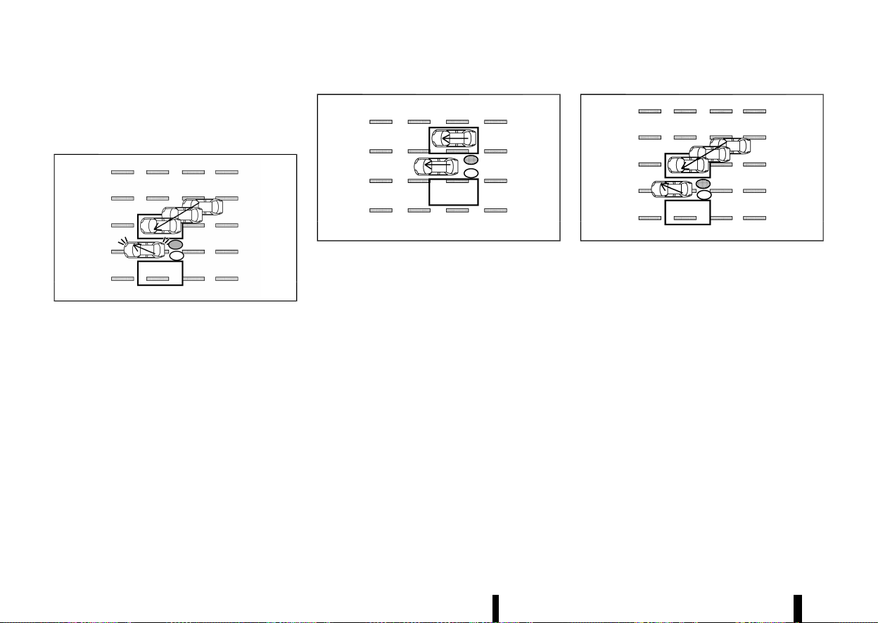
(306,1)
302 Starting and driving
NOTE:
The radar sensors may not detect a vehicle
which is travelling at about the same speed as
your vehicle when it enters the detection zone.
MWAF0555X
Illustration 8 - Entering from the side
Illustration 8: If the driver activates the turn signal
while another vehicle is in the detection zone, then
the side indicator light and Intelligent Blind Spot
Intervention indicator flash and a chime will sound
twice.
NOTE:
If the driver activates the turn signal before a
vehicle enters the detection zone, the side
indicator light and Intelligent Blind Spot Inter-
vention indicator will flash but no chime will
sound when another vehicle is detected.
MJVS0761X
Illustration 9 - Entering from the side
Illustration 9: If the Intelligent Blind Spot Interven-
tion system is on and your vehicle approaches the
lane marker while another vehicle is in the detec-
tion zone, the system chimes (three times) and the
side indicator light and Intelligent Blind Spot
Intervention indicator flash. The Intelligent Blind
Spot Intervention system activates by applying the
brakes on one side of the vehicle for a short period
of time to help return the vehicle back to the
centre of the driving lane.
MJVS0742X
Illustration 10 - Entering from the side
Illustration 10: The Intelligent Blind Spot Interven-
tion system will not operate if your vehicle is on a
lane marker when another vehicle enters the
detection zone. In this case only the BSW system
operates.
NOTE:
* The radar sensors may not detect a vehicle
which is travelling at about the same speed
as your vehicle when it enters the detection
zone.
* The Intelligent Blind Spot Intervention will
not operate or will stop operating and only a
warning chime will sound under the follow-
ing conditions.
— When the brake pedal is depressed.
— When the vehicle is accelerated during the
Intelligent Blind Spot Intervention system
operation
— When steering quickly
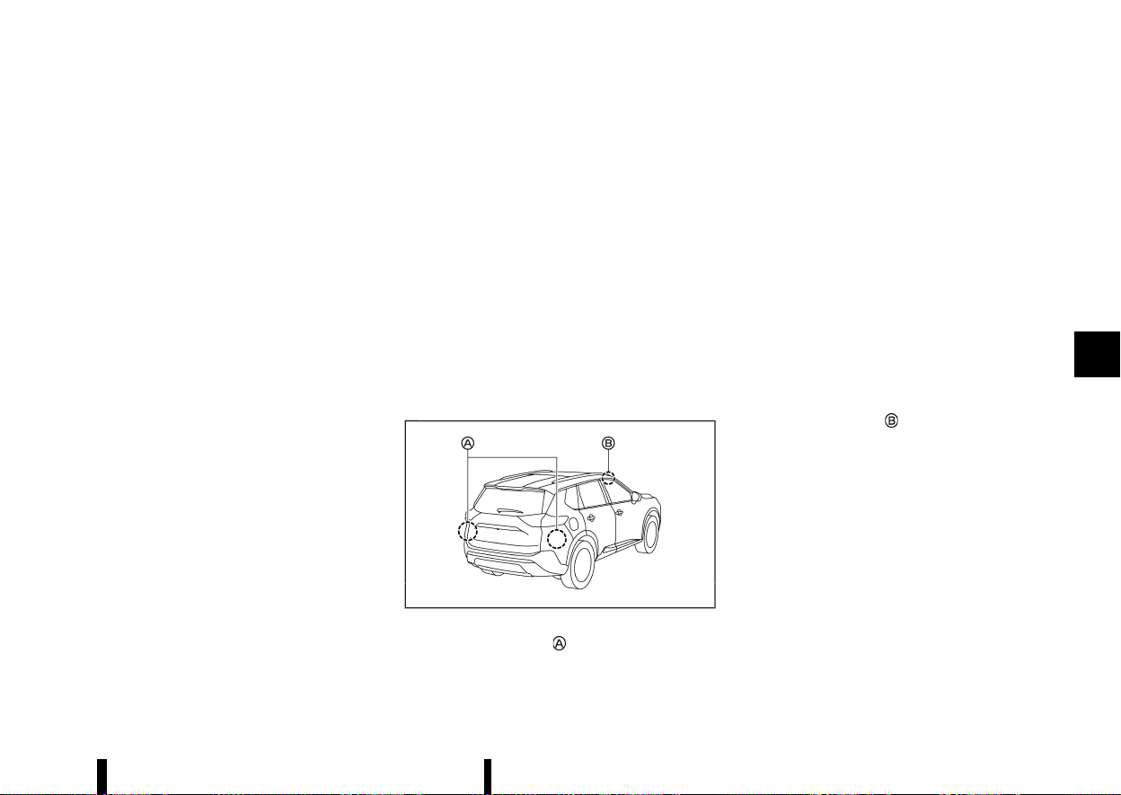
(307,1)
— When the ICC, Intelligent Forward Collision
Warning or Intelligent Emergency Braking
with Pedestrian Detection warnings
sound.
— When the hazard warning flashers are
operated.
— When driving on a curve at a high speed.
— When the BSW system is turned off.
SYSTEM TEMPORARILY UNAVAILABLE
MEVT33A1-37E58EF6-4253-4547-9045-60DB4ADC93AD
When any of the following messages appear on
the vehicle information display, a chime will sound
and the Intelligent Blind Spot Intervention system
will be turned off automatically.
* [Unavailable Slippery Road]:
When the VDC/ESP system (except traction
control system function) or ABS operates.
* [Currently Not Available]:
— When the VDC/ESP system is turned off.
* [Unavailable Camera Temperature High]:
If the vehicle is parked in direct sunlight under
high temperature conditions (over approxi-
mately 40°C (104°F)).
* [Not available Side radar obstructed]:
When side radar blockage is detected.
Turn off the Intelligent Blind Spot Intervention
system and turn it on again when the above
conditions no longer exist.
SYSTEM MALFUNCTION
MEVT33A1-DA0F4C9F-4080-49DE-B2F0-D757283877F5
When the Intelligent Blind Spot Intervention sys-
tem malfunctions, it will be turned off automati-
cally, the Intelligent Blind Spot Intervention
indicator illuminates and a chime will sound, and
the [System fault See Owner’s Manual] warning
message will appear in the vehicle information
display.
Action to take:
Stop the vehicle in a safe location and push the
park button to engage the "P" (Park) position. Turn
the engine off and restart the engine. If the
warning message continues to appear, It is re-
commended you visit a NISSAN dealer or qualified
workshop for this service.
SYSTEM MAINTENANCE
MEVT33A1-46E5EBC8-44FD-4514-B075-C66A9E0E8A6F
MWAF0633X
The two radar sensors for the Intelligent Blind
Spot Intervention system are located near the rear
bumper. Always keep the area near the radar
sensors clean.
The radar sensors may be blocked by temporary
ambient conditions such as splashing water, mist
or fog.
The blocked condition may also be caused by
objects such as ice, frost or dirt obstructing the
radar sensors.
Check for and remove objects obstructing the area
around the radar sensors.
Do not attach stickers (including transparent
material), install accessories or apply additional
paint near the radar sensors.
Do not strike or damage the area around the radar
sensors.
It is recommended you visit a NISSAN dealer or
qualified workshop if the area around the radar
sensors is damaged due to a collision.
The lane camera unit
for the Intelligent Blind
Spot Intervention system is located above the
inside mirror. To keep the proper operation of the
Intelligent Blind Spot Intervention and prevent a
system malfunction, be sure to observe the
following:
* Always keep the windscreen clean.
* Do not attach a sticker (including transparent
material) or install an accessory near the
camera unit.
* Do not place reflective materials, such as white
paper or a mirror, on the instrument panel.
The reflection of sunlight may adversely affect
the camera unit’s capability of detecting the
lane markers.
Starting and driving 303

(308,1)
304 Starting and driving
* Do not strike or damage the areas around the
camera unit. Do not touch the camera lens or
remove the screw located on the camera unit.
It is recommended you contact a NISSAN
dealer or qualified workshop if the camera
unit is damaged due to an accident.
Precautions on repairing the bumper
MEVT33A1-A1DCAEDD-E2A0-42CE-876E-DB2768A3875B
When repairing the bumper, take cautious because
the radar sensors are installed on the bumper. For
more details, see “Precautions on repairing the
bumper” (P.294).
MEVT33A1-212332F5-370C-44DF-B5A2-9C89439133B0
WARNING
Failure to follow the warnings and instructions
for proper use of the RCTA system could result
in serious injury or death.
* The RCTA system is not a replacement for
proper driving procedures and is not de-
signed to prevent contact with vehicles or
objects. When reversingout of a parking
space, always use the side and rear mirrors
and turn and look in the direction your
vehicle will move. Never rely solely on the
RCTA system.
The RCTA system will assist you when reversing-
out from a parking space. When the vehicle is in
reverse, the system is designed to detect other
vehicles approaching from the right or left of the
vehicle. If the system detects cross traffic, it will
alert you.
REAR CROSS TRAFFIC ALERT
(RCTA) (where fitted)
REAR CROSS TRAFFIC ALERT
(RCTA) (where fitted)
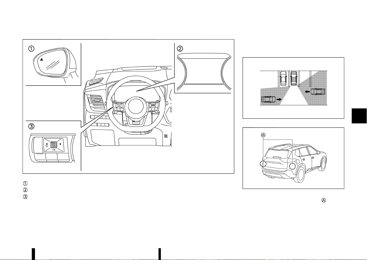
(309,1)
MWAF0416X
Side indicator light
Vehicle information display
Steering-wheel-mounted controls (left side)
RCTA SYSTEM OPERATION
MEVT33A1-5E3DBCD2-534F-4094-A7FF-3E1513EFB182
The RCTA system can help alert the driver of an
approaching vehicle when the driver is reversing-
out of a parking space.
When the shift position is in R (Reverse) and the
vehicle speed is less than approximately 8 km/h (5
MPH), the RCTA system is operational.
If the radar detects an approaching vehicle from
either side, the system chimes (once) and the side
indicator light flashes on the side the vehicle is
approaching from.
MJVS0173X
MWAF0414X
The RCTA system uses radar sensors installed
on both sides near the rear bumper to detect an
approaching vehicle.
The radar sensors can detect an approaching
vehicle from up to approximately 20 m (66 ft) away.
Starting and driving 305
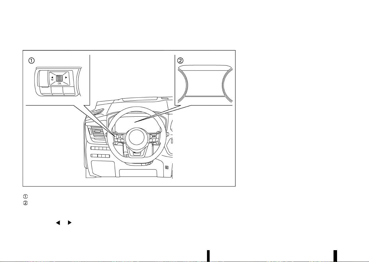
(310,1)
306 Starting and driving
HOW TO ENABLE/DISABLE THE RCTA SYSTEM
MEVT33A1-1A458B05-9324-4A27-8593-FB5F7795B76F
MWAF0412X
Steering-wheel-mounted controls (left side)
Vehicle information display
Perform the following steps to enable or disable
the RCTA system.
1. Push the
button until [Settings]
appears in the vehicle information display
and then push the scroll dial. Use the scroll
dial to select [Driver Assistance]. Then push the
scroll dial.
2. Select [Rear Cross Traffic Alert] and push the
scroll dial to turn the system on or off.
NOTE:
The system setting will be retained even if the
engine is restarted.
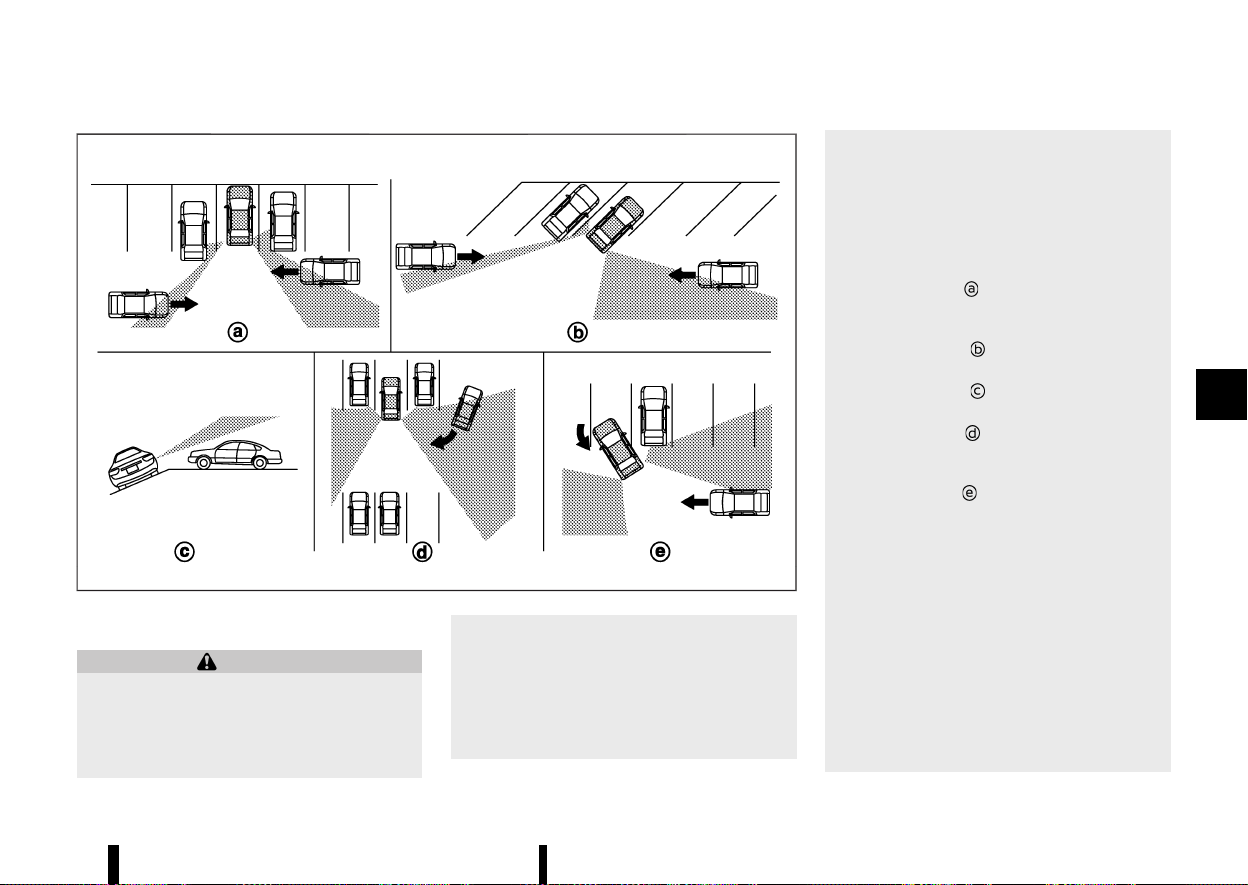
(311,1)
MJVS0479X
RCTA SYSTEM LIMITATIONS
MEVT33A1-AE9890E0-04F7-4C4C-A626-8DD36B90F3CF
WARNING
Listed below are the system limitations for the
RCTA system. Failure to operate the vehicle in
accordance with these system limitations
could result in serious injury or death.
* Always check surroundings and turn to
check what is behind you before reversing.
The radar sensors detect approaching
(moving) vehicles. The radar sensors can-
not detect every object such as:
— Pedestrians, bicycles, motorcycles, an-
imals or child-operated toy vehicles
— A vehicle that is passing at speeds
greater than approximately 30 km/h
(19 MPH)
— A vehicle that is passing at speeds
lower than approximately 8 km/h (5
MPH)
* The radar sensors may not detect ap-
proaching vehicles in certain situations:
— Illustration
: When a vehicle parked
next to you obstructs the beam of the
radar sensor.
— Illustration
: When the vehicle is
parked in an angled parking space.
— Illustration
: When the vehicle is
parked on inclined ground.
— Illustration
: When an approaching
vehicle turns into your vehicle’s park-
ing lot aisle.
— Illustration
: When the angle formed
by your vehicle and approaching ve-
hicle is small
* The following conditions may reduce the
ability of the radar to detect other vehicles:
— Severe weather
— Road spray
— Ice/frost/dirt build-up on the vehicle
* Do not attach stickers (including transpar-
ent material), install accessories or apply
additional paint near the radar sensors.
These conditions may reduce the ability of
the radar to detect other vehicles
* When towing a trailer or other vehicle, turn
Starting and driving 307
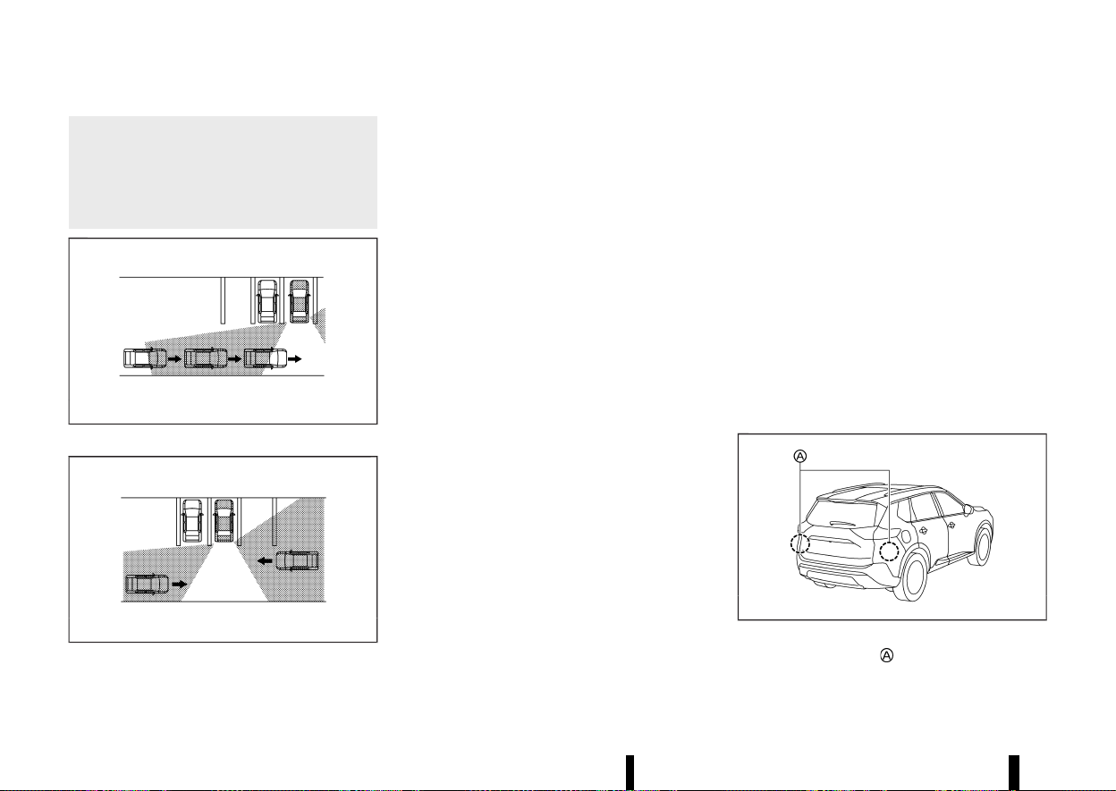
(312,1)
308 Starting and driving
the RCTA system off to prevent the occur-
rence of an unexpected accident resulting
from sudden system operation.
* Excessive noise (e.g. audio system volume,
open vehicle window) will interfere with
the chime sound, and it may not be heard.
MJVS0172X
Illustration 1
MJVS0173X
Illustration 2
NOTE:
In the case of several vehicles approaching in a
row (Illustration 1) or in the opposite direction
(Illustration 2), a chime may not be sounded by
the RCTA system after the first vehicle passes
the sensors.
SYSTEM TEMPORARILY UNAVAILABLE
MEVT33A1-09B800FF-C822-42DE-BF7C-41CED2459499
When radar blockage is detected, the system will
be deactivated automatically. The [Not available
Side radar obstructed] warning message will
appear in the vehicle information display.
The systems are not available until the conditions
no longer exist.
The radar sensors may be blocked by temporary
ambient conditions such as splashing water, mist
or fog.
The blocked condition may also be caused by
objects such as ice, frost or dirt obstructing the
radar sensors.
NOTE:
If the BSW system stops working, the RCTA and
the Intelligent Blind Spot Intervention (where
fitted) systems will also stop working.
Action to take:
When the above conditions no longer exist, the
system will resume automatically.
SYSTEM MALFUNCTION
MEVT33A1-1268FF40-FFAA-4D31-919A-B6261E4E3E5A
When the RCTA system malfunctions, it will turn off
automatically. The [System fault See Owner’s
Manual] warning message will appear in the
vehicle information display.
NOTE:
If the BSW system stops working, the RCTA and
the Intelligent Blind Spot Intervention (where
fitted) systems will also stop working.
Action to take:
Stop the vehicle in a safe location, turn the engine
off and restart the engine. If the message con-
tinues to appear, have the system checked. It is
recommended that you visit a NISSAN dealer or
qualified workshop for this service.
SYSTEM MAINTENANCE
MEVT33A1-27B6E548-16CE-4293-96C2-975F659E4855
MWAF0414X
The two radar sensors for the RCTA system are
located near the rear bumper. Always keep the
area near the radar sensors clean.
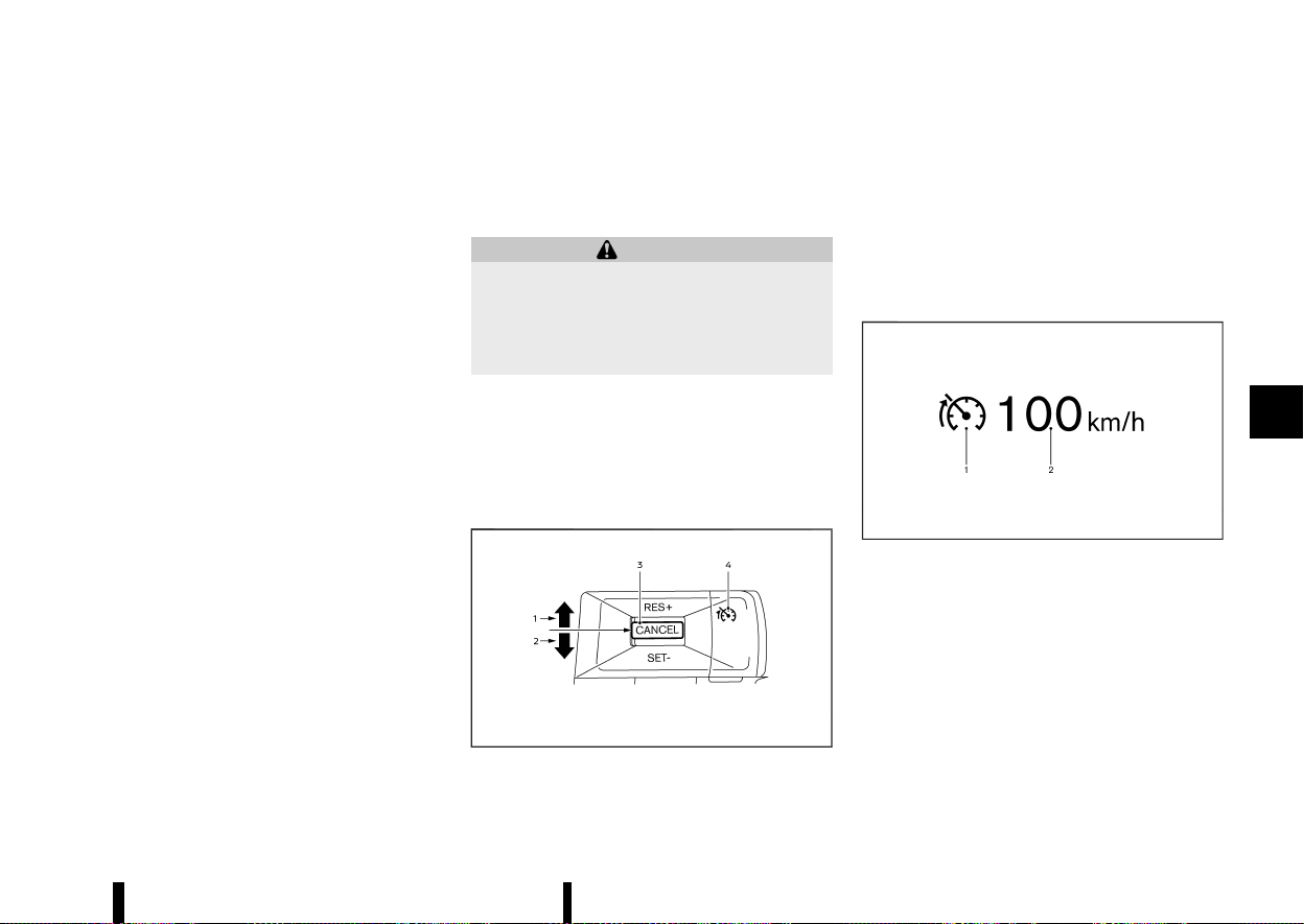
(313,1)
The radar sensors may be blocked by temporary
ambient conditions such as splashing water, mist
or fog.
The blocked condition may also be caused by
objects such as ice, frost or dirt obstructing the
radar sensors.
Check for and remove objects obstructing the area
around the radar sensors.
Do not attach stickers (including transparent
material), install accessories or apply additional
paint near the radar sensors.
Do not strike or damage the area around the radar
sensors. It is recommended that you visit a NISSAN
dealer or qualified workshop if the area around the
radar sensors is damaged due to a collision.
Precautions on repairing the bumper
MEVT33A1-953DA44C-2DBE-45FC-9637-093705C40D8D
When repairing the bumper, take cautious because
the radar sensors are installed on the bumper. For
more details, see “Precautions on repairing the
bumper” (P.294).
MEVT33A1-131C307F-FF63-48FD-A763-1DAB78A699E4
The speed limiter allows you to set the desired
vehicle speed limit. While the speed limiter is
activated, the driver can perform normal braking
and acceleration, but the vehicle will not exceed
the set speed.
WARNING
* Always observe posted speed limits. Do
not set the speed over them.
* Always confirm the setting status of the
speed limiter on the vehicle information
display.
When the speed limiter is on, the cruise control
(where fitted) system cannot be operated.
SPEED LIMITER OPERATIONS
MEVT33A1-07A8ACF4-40B8-4068-BBE9-52A63E3A6097
The speed limiter can be set at a speed between
the following speeds.
* 30 to 200 km/h (20 to 125 MPH)
MWAF1178X
The speed limiter set switches are located on the
steering wheel.
1. <RES+> switch
2. <SET-> switch
3. <CANCEL> switch
4. Speed limiter MAIN switch (When this switch
is pushed, the speed limiter enters the
standby mode. If the cruise control (where
fitted) or ICC system (where fitted) is on, the
system will turn off and the speed limiter
enters the standby mode.)
MJVS0284X
The speed limiter operating condition is shown on
the vehicle information display.
1. Speed limiter indicator
2. Set speed indicator
The speed unit can be converted between [km/h]
and [MPH]. (See “[Unit/Language]” (P.89).)
When the vehicle speed exceeds the set speed
limit, the set speed indicator blinks and the
accelerator pedal operation will not work until
the vehicle speed slows down to the set speed
limit.
Starting and driving 309
SPEED LIMITER (where fitted)
SPEED LIMITER (where fitted)

(314,1)
310 Starting and driving
The speed limiter will not automatically reduce
the vehicle speed to the set speed limit.
Turning on speed limiter
MEVT33A1-3E25176E-2C5D-4968-9FA9-A7202535E449
Push the speed limiter MAIN switch. The speed
limiter and the set speed indicators illuminate on
the vehicle information display ([LIMIT ON Press
SET- to Activate] message appears on the display).
Setting speed limit
MEVT33A1-C1EBF3B3-A2CA-4B94-9EC6-E17983D81793
1. Push the <SET−> switch.
.
When the vehicle is stopped, the speed will
be set at 30 km/h or 20 MPH.
.
While driving, the speed limit will be set at
the current speed.
NOTE:
If you push the <RES+> switch and release
it when there is no vehicle set speed, the
vehicle will behave the same way as when
the <SET-> switch is pushed.
2. When the speed limit is set, the speed limiter
indicator and the set speed indicator illumi-
nate on the vehicle information display ([+/-
Change Set Speed] message appears on the
display).
Changing set speed limit:
Use either of the following operations to change
the speed limit.
* Push and hold the <RES+> or <SET-> switch.
The set speed will increase or decrease by
approximately 5 km/h or 5 MPH.
* Push, then quickly release the <RES+> or <SET-
> switch. Each time you do this, the set speed
will increase or decrease by approximately 1
km/h or 1 MPH.
The new set speed limit value will be displayed in
the vehicle information display.
When the actual vehicle speed exceeds the set
speed, an audible warning will be heard a short
time after the set speed is exceeded if driver
intervention is not detected.
Cancelling speed limit
MEVT33A1-1F1749FC-9566-4392-B9FB-7061B9E9A809
To cancel the speed limiter, push the <CANCEL>
switch. The speed limiter indicator and the set
speed indicator on the vehicle information display
will turn off ([Standby Press RES+ to Resume]
message appears on the display).
It is also possible to override the speed limiter by
fully depressing the accelerator pedal beyond the
resistance point.
WARNING
* The vehicle may accelerate when the
speed limiter cancels.
* When additional floor mats are used, be
sure that they are correctly secured and
that they cannot interfere with the accel-
erator pedal. Mats not adapted to the
vehicle may prevent proper operation of
the speed limiter.
Fully depress the accelerator pedal beyond the
resistance point. The speed limiter will be sus-
pended to allow driving above the set speed. The
set speed indicator will flash. The speed limiter will
automatically resume when the vehicle speed
drops below the set speed limit.
Resuming a previous set speed
MEVT33A1-2485CD01-45D2-481B-87F8-D6DFE56F3F88
If a set speed limit has been cancelled, the set
speed will be stored in the speed limiter memory.
This speed limit can be reactivated by pressing the
<RES+> switch upwards ([Resumed] message ap-
pears on the display).
If the current vehicle speed is higher than the
previous set speed, the accelerator pedal will not
work and the set speed indicator will flash until the
vehicle speed drops below the set speed limit.
When the actual vehicle speed exceeds the set
speed, an audible warning will be heard a short
time after the set speed is exceeded and driver
intervention is not detected.
Turning the speed limiter off
MEVT33A1-8236A3C3-3CD8-4EB8-9297-E8B96AC84599
The speed limiter system will be turned off when
one of the following operations is performed:
* Push the speed limiter MAIN switch. The speed
limiter indicator and the set speed indicator on
the vehicle information display will be turned
off.
* Push the Cruise ON/OFF switch. The speed
limiter information on the vehicle information
will be replaced with the cruise control in-
formation. For details see “Cruise control
(where fitted)” (P.311).
* When the vehicle is stopped and the ignition
switch is placed in the “OFF” position.
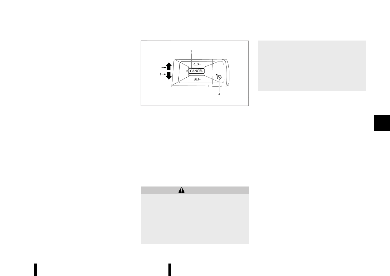
(315,1)
Turning off the speed limiter will erase the set
speed limit memory.
Speed limiter malfunction
MEVT33A1-49B58CA9-70C1-48B6-A0D6-502DA241DC7A
If the speed limiter malfunctions, the speed limiter
on the vehicle information display will flash ([LIMIT
Not Available] message appears on the display).
Turn the speed limiter MAIN switch off and have
the system checked by a certified NISSAN dealer or
qualified workshop.
MEVT33A1-3CB05FA0-A686-48B9-AC8C-D8BD471B4E3D
MWAF0421X
1. <RES+> switch
2. <SET-> switch
3. <CANCEL> switch
4. Cruise ON/OFF switch
For models with the ProPILOT Assist system, see
“Conventional (fixed speed) cruise control mode”
(P.356).
For models with the Intelligent Cruise Control (ICC)
system (without ProPILOT Assist system), see
“Conventional (fixed speed) cruise control mode”
(P.326).
WARNING
* Always observe the posted speed limits
and do not set the speed over them.
* Do not use the cruise control when driving
under the following conditions. Doing so
could cause a loss of vehicle control and
result in an accident.
— When it is not possible to keep the
vehicle at a constant speed
— When driving in heavy traffic
— When driving in traffic that varies
speed
— When driving in windy areas
— When driving on winding or hilly roads
— When driving on slippery (rain, snow,
ice, etc.) roads
PRECAUTIONS ON CRUISE CONTROL
MEVT33A1-C1B3FBF6-66A0-4E6D-A05B-28AC5FADAA48
* If the cruise control system malfunctions, it will
cancel automatically. The cruise indicator in
the vehicle information display will then blink
to warn the driver.
* If the cruise indicator blinks and [Not Available
Cruise System Fault] message appears in the
display, turn the Cruise ON/OFF switch off and
have the system checked. It is recommended
that you visit a NISSAN dealer or qualified
workshop for this service.
* The cruise indicator may blink when the Cruise
ON/OFF switch is turned ON while pushing up
the <RES+>, pushing down the <SET->, or
pushing the <CANCEL> switch. To properly
set the cruise control system, perform the
following procedures.
Starting and driving 311
CRUISE CONTROL (where fitted)
CRUISE CONTROL (where fitted)

(316,1)
312 Starting and driving
CRUISE CONTROL OPERATIONS
MEVT33A1-F2559FA0-5502-40A0-AC47-17C1EEC38DDF
The cruise control allows driving at speeds above
30 km/h (20 MPH) without keeping your foot on
the accelerator pedal.
The cruise control will automatically be cancelled if
the vehicle slows down more than approximately
13 km/h (8 MPH) below the vehicle set speed. ([Not
Available Speed Too High/Low] message appears
in the display.)
Moving the shift lever to the N (Neutral) position
will cancel the cruise control.
Turning on cruise control
MEVT33A1-2303B217-4FD0-413F-9ACF-24035E3291A0
Push the Cruise ON/OFF switch. The cruise in-
dicator and [CRUISE ON Press SET- to Activate]
message in the vehicle information display will
appear.
Setting cruising speed
MEVT33A1-A7FAD722-AEBE-46FA-9992-CC007883E58A
1. Accelerate to the desired speed.
2. Push the <SET-> switch down or <RES+>
switch up and release it.
3. Take your foot off the accelerator pedal.
The vehicle will maintain the set speed. ([+ /-
Change Set Speed] message appears in the dis-
play.)
NOTE:
If pushed the <RES+> switch and released it
when there is no vehicle set speed, the set speed
is set to the current vehicle speed.
Passing another vehicle:
Depress the accelerator pedal to accelerate. After
releasing the accelerator pedal, the vehicle will
return to the previously set speed.
The vehicle may not maintain the set speed when
going up or down steep hills. In such cases, drive
without the cruise control.
Resetting to slower speed:
Use any one of the following methods to reset to a
slower speed.
* Lightly tap the footbrake pedal. When the
vehicle reaches the desired speed, push down
and release the <SET-> switch.
* Push down and hold the <SET-> switch. This
will reduce the vehicle speed by about 5km/h
or 5 MPH. When the vehicle reaches the
desired speed, release the <SET-> switch.
* Quickly push down and release the <SET->
switch. This will reduce the vehicle speed by
about 1 km/h or 1 MPH.
Resetting to faster speed:
Use any one of the following methods to reset to a
faster speed.
* Depress the accelerator pedal. When the
vehicle reaches the desired speed, push down
and release the <SET-> switch.
* Push up and hold the <RES+> switch. This will
increase the vehicle speed by about 5 km/h or
5 MPH. When the vehicle reaches the desired
speed, release the <RES+> switch.
* Quickly push up and release the <RES+>
switch. This will increase the vehicle speed by
about 1 km/h or 1 MPH.
Resuming at preset speed:
Push up and release the <RES+> switch.
The vehicle will resume the last set cruising speed
when the vehicle speed is over 30 km/h (20 MPH).
([Resumed] message appears in the display.)
Cancelling cruising speed
MEVT33A1-88B40337-C20C-48AF-BB19-137F7A6ECAF7
Use any one of the following methods to cancel
the vehicle set speed. ([Standby Press RES+ to
Resume] message appears in the display.)
* Push the <CANCEL> switch.
* Tap the footbrake pedal.
* Push the Cruise ON/OFF switch. The cruise
indicator will turn off.

(317,1)
MEVT33A1-1652888D-9B7D-476C-BF9F-DCBE2B282328
For models with the ProPILOT Assist system, see
“Intelligent Cruise Control (ICC)” (P.339).
WARNING
Failure to follow the warnings and instructions
for proper use of the ICC system could result in
serious injury or death.
* ICC is not a collision avoidance or warning
device. It is intended for highway use only
and it is not intended for congested areas
or city driving. Failure to apply the brakes
could result in an accident.
* The ICC system is only an aid to assist the
driver and is not a collision warning or
avoidance device. It is the driver’s respon-
sibility to stay alert, drive safely, and be in
control of the vehicle at all times.
* Always observe posted speed limits and do
not set the speed over them.
* Always drive carefully and attentively
when using either cruise control mode.
Read and understand the Owner’s Manual
thoroughly before using the cruise control.
To avoid serious injury or death, do not rely
on the system to prevent accidents or to
control the vehicle’s speed in emergency
situations. Do not use cruise control except
in appropriate road and traffic conditions.
* In the conventional (fixed speed) cruise
control mode, a warning chime will not
sound to warn you if you are too close to
the vehicle ahead. Pay special attention to
the distance between your vehicle and the
vehicle ahead of you or a collision could
occur.
The ICC system will maintain a constant set speed
or keep a set distance from the vehicle in front of
you up to the set speed.
The vehicle travels at a set speed when the road
ahead is clear.
The ICC system can be set to one of two cruise
control modes.
* Vehicle-to-vehicle distance control mode:
For maintaining a selected distance between
your vehicle and the vehicle in front of you up
to the preset speed.
* Conventional (fixed speed) cruise control
mode:
For cruising at a preset speed.
The ICC system cannot be operated when the
speed limiter is on. (See “Speed limiter (where
fitted)” (P.309).)
Starting and driving 313
INTELLIGENT CRUISE CONTROL
(ICC) (where fitted)
INTELLIGENT CRUISE CONTROL
(ICC) (where fitted)
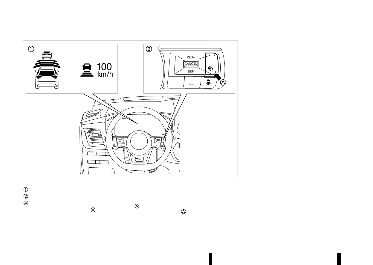
(318,1)
314 Starting and driving
MWAF1179X
Example
Displays and indicators
ICC switches
Cruise ON/OFF switch
Push the Cruise ON/OFF switch
to choose the
cruise control mode between the vehicle-to-vehi-
cle distance control mode and the conventional
(fixed speed) cruise control mode.
Once a control mode is activated, it cannot be
changed to the other cruise control mode. To
change the mode, push the Cruise ON/OFF switch
once to turn the system off. Then push the
Cruise ON/OFF switch
again to turn the system
back on and select the desired cruise control
mode.
Always confirm the setting in the ICC system
display.
For the vehicle-to-vehicle distance control mode,
see “Vehicle-to-vehicle distance control mode”
(P.315).
For the conventional (fixed speed) cruise control
mode, see “Conventional (fixed speed) cruise con-
trol mode” (P.326).
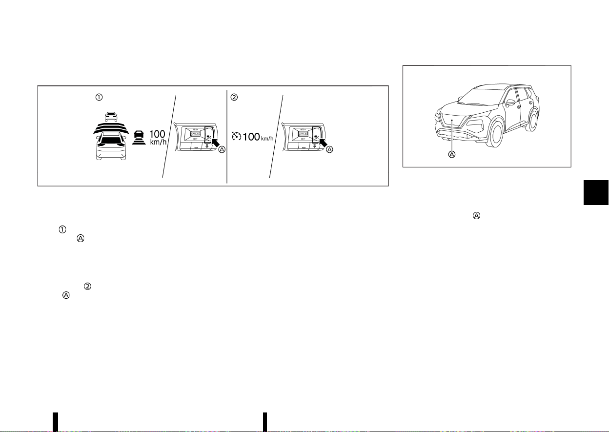
(319,1)
HOW TO SELECT THE CRUISE CONTROL MODE
MEVT33A1-97B82C3A-7850-4CF1-A046-B3ADC1CC80D8
MWAF1180X
Example
Selecting the vehicle-to-vehicle distance control mode
MEVT33A1-A5616025-1FCA-42AE-85F5-090609976C80
To choose the vehicle-to-vehicle distance control
mode
, quickly push and release the Cruise ON/
OFF switch
.
Selecting the conventional (fixed
speed) CRUISE CONTROL MODE
MEVT33A1-9D971814-D7DF-40D4-8E51-6128A42348CB
To choose the conventional (fixed speed) cruise
control mode
, push and hold the Cruise ON/OFF
switch
for longer than approximately 1.5 sec-
onds. See “Conventional (fixed speed) cruise con-
trol mode” (P.326).
VEHICLE-TO-VEHICLE DISTANCE CON-
TROL MODE
MEVT33A1-5AD2A826-7CD1-4419-862A-54DAB1FCCA29
In the vehicle-to-vehicle distance control mode,
the ICC system automatically maintains a selected
distance from the vehicle travelling in front of you
according to that vehicle’s speed (up to the set
speed), or at the set speed when the road ahead is
clear.
MWAF0646X
The system is intended to enhance the operation
of the vehicle when following a vehicle travelling in
the same lane and direction.
If the radar sensor
detects a slower moving
vehicle ahead, the system will reduce the vehicle
speed so that your vehicle follows the vehicle in
front at the selected distance.
The system automatically controls the throttle and
applies the brakes (up to approximately 40% of
vehicle braking power) if necessary.
Vehicle-to-vehicle distance control mode operation
MEVT33A1-3193CD19-44D5-48A5-A5A0-52A085441568
The vehicle-to-vehicle distance control mode is
designed to maintain a selected distance and
reduce the speed to match the slower vehicle
ahead; the system will decelerate the vehicle as
necessary. However, the ICC system can only apply
up to approximately 40% of the vehicle’s total
braking power. This system should only be used
when traffic conditions allow vehicle speeds to
remain fairly constant or when vehicle speeds
change gradually. If a vehicle moves into the
Starting and driving 315
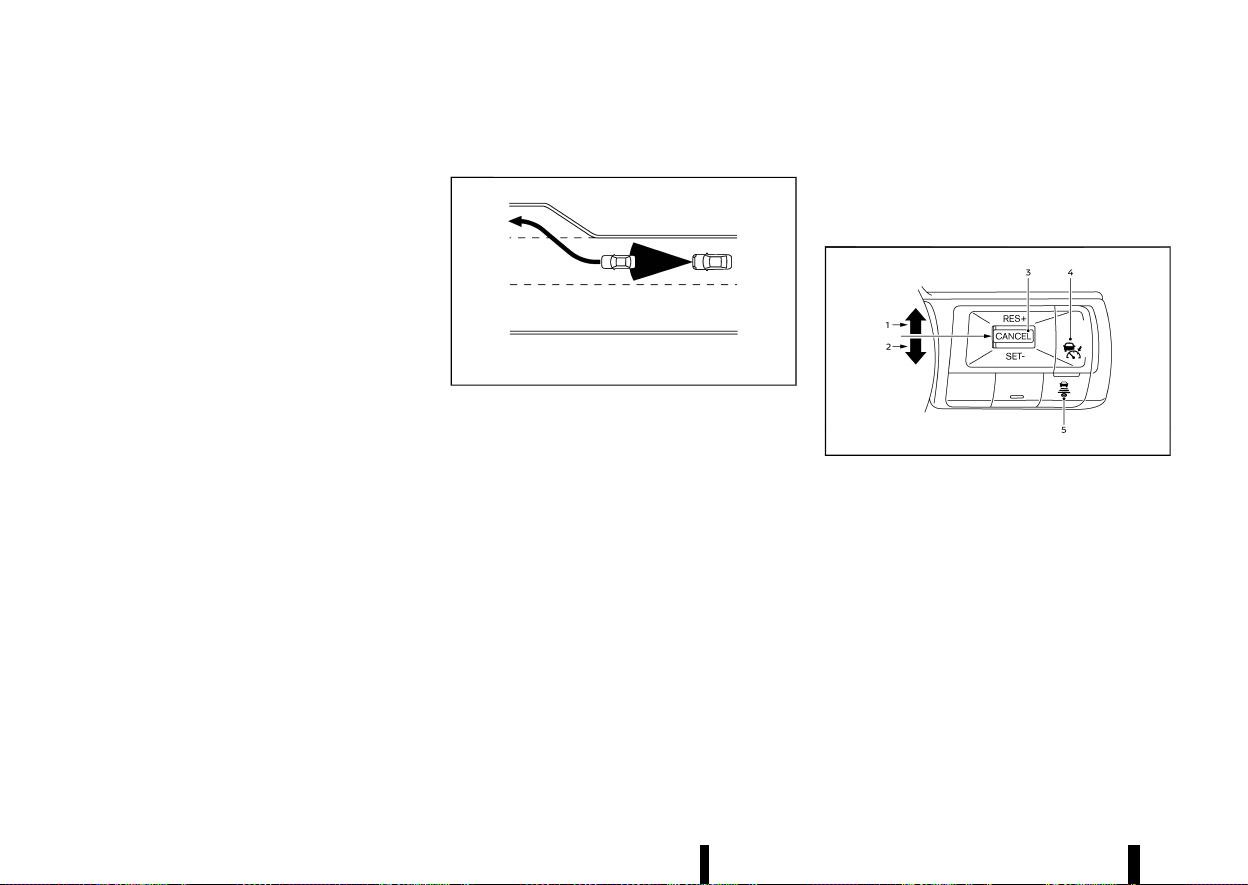
(320,1)
316 Starting and driving
travelling lane ahead or if a vehicle travelling ahead
rapidly decelerates, the distance between vehicles
may become closer because the ICC system
cannot decelerate the vehicle quickly enough. If
this occurs, the ICC system will sound a warning
chime and blink the system display to notify the
driver to take necessary action.
The system will cancel and a warning chime will
sound if the speed is below approximately 25 km/h
(15 MPH) and a vehicle is not detected ahead.
The following items are controlled in the vehicle-
to-vehicle distance control mode:
* When there are no vehicles travelling ahead,
the vehicle-to-vehicle distance control mode
maintains the speed set by the driver. The set
speed range is the following speed.
— 30 and 180 km/h (20 and 112 MPH)
* When there is a vehicle travelling ahead, the
vehicle-to-vehicle distance control mode ad-
justs the speed to maintain the distance,
selected by driver, from the vehicle ahead.
The adjusting speed range is between ap-
proximately 30 km/h (20 MPH) and up to the
set speed.
* When the vehicle travelling ahead has moved
out from its lane of travel, the vehicle-to-
vehicle distance control mode accelerates
and maintains vehicle speed up to the set
speed.
The ICC system does not control vehicle speed or
warn you when you approach stationary and slow
moving vehicles. You must pay attention to vehicle
operation to maintain proper distance from vehi-
cles ahead when approaching toll gates or traffic
congestion.
MSSD0254
When driving on the freeway at a set speed and
approaching a slower travelling vehicle ahead, the
ICC system will adjust the speed to maintain the
distance, selected by the driver, from the vehicle
ahead. If the vehicle ahead changes lanes or exits
the freeway, the ICC system will accelerate and
maintain the speed up to the set speed. Pay
attention to the driving operation to maintain
control of the vehicle as it accelerates to the set
speed.
The vehicle may not maintain the set speed on
winding or hilly roads. If this occurs, you will have
to manually control the vehicle speed.
Normally when controlling the distance to a
vehicle ahead, this system automatically acceler-
ates or decelerates your vehicle according to the
speed of the vehicle ahead. Depress the accel-
erator to properly accelerate your vehicle when
acceleration is required for a lane change. Depress
the brake pedal when deceleration is required to
maintain a safe distance to the vehicle ahead due
to its sudden braking or if a vehicle cuts in. Always
stay alert when using the ICC system.
Vehicle-to-vehicle distance control mode switches
MEVT33A1-7A2E11BF-D743-46FC-8A90-75A74B2EE68F
MWAF1181X
The system is operated by a Cruise ON/OFF switch
and four control switches, all mounted on the
steering wheel.
1. <RES+> switch:
Resumes set speed or increases speed incre-
mentally.
2. <SET-> switch:
Sets desired cruise speed, reduces speed
incrementally.
3. <CANCEL> switch:
Deactivates the system without erasing the
set speed.
4. Cruise ON/OFF switch:
Master switch to activate the system
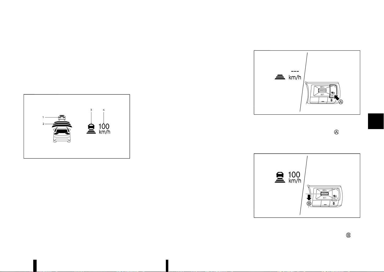
(321,1)
5. DISTANCE switch:
Changes the vehicle’s following distance:
.
[Far]
.
[Middle]
.
[Short]
Vehicle-to-vehicle distance control
mode display and indicators
MEVT33A1-AAB412E0-888E-4B31-BBEF-A89270610BC1
MWAF1182X
Example
The display is located on the left side of the
speedometer.
1. Vehicle ahead detection indicator:
Indicates whether it detects a vehicle in front
of you (only when ICC is active).
2. Set distance indicator:
Displays the selected distance between vehi-
cles set with the DISTANCE switch.
3. This indicator indicates the ICC system status
using colour.
.
ICC system ON indicator (grey):
ICC standby.
.
ICC system ON indicator (green):
Indicates that the ICC system is ON and
active.
Indicates that the cruising speed is set.
— Green vehicle icon displayed: Vehicle
detected ahead.
— No vehicle icon shown: No vehicle de-
tected ahead. (Your vehicle maintains
the driver-selected set speed.)
.
ICC system warning (yellow):
Indicates that there is a malfunction in the
ICC system.
4. Set vehicle speed indicator:
Indicates the set vehicle speed.
.
Green: ICC active
.
Grey: ICC standby
(The speed unit can be converted between
"km/h" and "MPH". See “[Unit/Language]”
(P.89).)
Operating vehicle-to-vehicle distance control mode
MEVT33A1-C2FAA690-C86C-4BFD-9CF8-F92CB3A1F3CF
MWAF1183X
To turn on the cruise control, quickly push and
release the Cruise ON/OFF switch
. The ICC
system ON indicator (grey), set distance indicator
and set vehicle speed indicator come on and in a
standby state for setting.
MWAF1184X
To set cruising speed, accelerate your vehicle to
the desired speed, push the <SET-> switch
and
Starting and driving 317
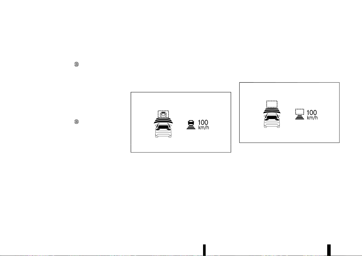
(322,1)
318 Starting and driving
release it. (The ICC system ON indicator (green), set
distance indicator and set vehicle speed indicator
come on.) Take your foot off the accelerator pedal.
Your vehicle will maintain the set speed.
When the <SET-> switch
is pushed under the
following conditions, the system cannot be set and
the set vehicle speed indicator will blink for
approximately 2 seconds:
* When travelling below 30 km/h (20 MPH) and
the vehicle ahead is not detected
* When the shift lever is not in the D (Drive)
position
* When the parking brake is applied
* When the brakes are operated by the driver
When the <SET-> switch
is pushed under the
following conditions, the system cannot be set and
a message will pop up.
* When the VDC/ESP system is off. (To use the
ICC system, turn on the VDC/ESP system. Push
the Cruise ON/OFF switch to turn off the ICC
system and reset the ICC system by pushing
the Cruise ON/OFF switch again.)
For additional information about the VDC/ESP
system, see “Vehicle Dynamic Control (VDC)/
Electronic Stability Programme (ESP) system”
(P.391).
* When VDC/ESP (including the traction control
system) is operating.
* When a wheel is slipping. (To use the ICC
system, make sure the wheels are no longer
slipping.)
* When the front radar is impaired due to dirt or
an other obstruction blocking the radar sen-
sor.
The driver sets the desired vehicle speed based on
the road conditions. The ICC system maintains the
set vehicle speed, similar to standard cruise
control, as long as no vehicle is detected in the
lane ahead.
The ICC system displays the set speed.
Vehicle detected ahead:
MWAF1185X
Example
When a vehicle is detected in the lane ahead, the
ICC system decelerates the vehicle by controlling
the throttle and applying the brakes to match the
speed of a slower vehicle ahead. The system then
controls the vehicle speed based on the speed of
the vehicle ahead to maintain the driver selected
distance.
NOTE:
* The stoplights of the vehicle come on when
braking is performed by the ICC system.
* When the brake operates, a noise may be
heard. This is not a malfunction.
When a vehicle ahead is detected, the vehicle
ahead detection indicator comes on. The ICC
system will also display the set speed and selected
distance.
Vehicle ahead not detected:
MWAF1186X
Example
When a vehicle is no longer detected ahead, the
ICC system gradually accelerates your vehicle to
resume the previously set vehicle speed. The ICC
system then maintains the set speed.
When a vehicle is no longer detected the vehicle
ahead detection indicator turns off.
If a vehicle ahead appears during acceleration to
the set vehicle speed or any time the ICC system is
in operation, the system controls the distance to
that vehicle.
When a vehicle is no longer detected under
approximately 25 km/h (15 MPH), the system will
be cancelled.
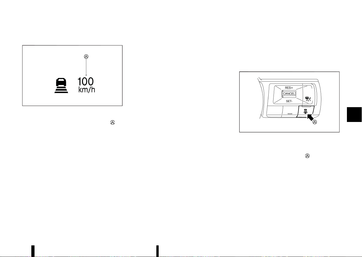
(323,1)
When passing another vehicle:
MWBF0178X
The driver can override ICC by depressing the
accelerator pedal. The set speed indicator
will
flash when the vehicle speed exceeds the set
speed. The vehicle detect indicator will turn off
when the area ahead of the vehicle is open. When
the pedal is released, the vehicle will return to the
previously set speed.
Even though your vehicle speed is set in the ICC
system, you can depress the accelerator pedal
when it is necessary to accelerate your vehicle
rapidly.
How to switch the ICC system off
MEVT33A1-48552384-F829-407C-8B86-31A4047F91D6
Switch off the ICC system completely by turning
the Cruise ON/OFF switch off. The ICC indicators
will go out.
How to change the set vehicle speed
MEVT33A1-81DFB76B-3B1A-4BEA-A894-1153CBB8D90D
To cancel the preset speed, use any of these
methods:
* Push the <CANCEL> switch. The set vehicle
speed indicator and the cruise indicator will
turn grey.
* Tap the brake pedal. The set vehicle speed
indicator and the cruise indicator will turn
grey.
* Turn the Cruise ON/OFF switch off. The ICC
indicators will go out.
To reset at a faster cruising speed, use one of the
following methods:
* Depress the accelerator pedal. When the
vehicle attains the desired speed, push and
release the <SET-> switch.
* Push and hold the <RES+> switch. The set
vehicle speed will increase in increments of 10
km/h or 5 MPH.
* Push, then quickly release the <RES+> switch.
Each time you do this, the set speed will
increase by approximately 1 km/h (1 MPH).
To reset at a slower cruising speed, use one of
the following methods:
* Lightly tap the brake pedal. When the vehicle
attains the desired speed, push the <SET->
switch and release it.
* Push and hold the <SET-> switch. The set
vehicle speed will decrease in increments of 10
km/h or 5 MPH.
* Push, then quickly release the <SET-> switch.
Each time you do this, the set speed will
decrease by approximately 1 km/h (1 MPH).
To resume the preset speed, push and release
the <RES+> switch. The vehicle will resume the last
set cruising speed when the vehicle speed is over
30km/h (20 MPH).
How to change the set distance to the vehicle ahead
MEVT33A1-17DBF70F-4DF6-4B13-8C83-32389A15AA53
MWAF1188X
The distance to the vehicle ahead can be selected
at the time of the ICC standby or the ICC is active.
Each time the DISTANCE switch
is pushed, the
set distance will change to long, middle, short and
back to long again in that sequence.
Starting and driving 319
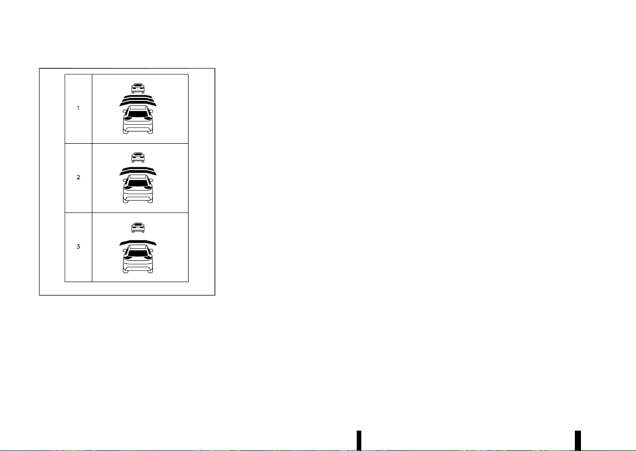
(324,1)
320 Starting and driving
MWAF1189X
Example
Distance — approximate distance at 100 km/h
(60 MPH)
1. Long – 60 m (200 ft)
2. Middle – 45 m (150 ft)
3. Short – 30 m (100 ft)
* The distance to the vehicle ahead will change
according to the vehicle speed. The higher the
vehicle speed, the longer the distance.
* The distance setting will remain at the current
setting even if the engine is restarted.
Approach warning
MEVT33A1-1718DFFB-6831-4611-AAF7-669DEE6BC500
If your vehicle comes closer to the vehicle ahead
due to rapid deceleration of that vehicle or if
another vehicle cuts in, the system warns the
driver with the chime and ICC system display.
Decelerate by depressing the brake pedal to
maintain a safe vehicle distance if:
* The chime sounds.
* The vehicle ahead detection indicator blinks.
The warning chime may not sound in some cases
when there is a short distance between vehicles.
Some examples are:
* When the vehicles are travelling at the same
speed and the distance between vehicles is
not changing.
* When the vehicle ahead is travelling faster and
the distance between vehicles is increasing.
* When a vehicle cuts in near your vehicle.
The warning chime will not sound when:
* Your vehicle approaches other vehicles that
are parked or moving slowly.
* The accelerator pedal is depressed, overriding
the system.
NOTE:
The approach warning chime may sound and
the system display may blink when the radar
sensor detects objects on the side of the vehicle
or on the side of the road. This may cause the
ICC system to decelerate or accelerate the
vehicle. The radar sensor may detect these
objects when the vehicle is driven on winding
roads, narrow roads, hilly roads or when enter-
ing or exiting a curve. In these cases you will
have to manually control the proper distance
ahead of your vehicle.
Also, the sensor sensitivity can be affected by
vehicle operation (steering manoeuvre or driving
position in the lane) or traffic or vehicle condition
(for example, if a vehicle is being driven with some
damage).
Acceleration when passing (where fitted)
MEVT33A1-9AEF4AE9-AB4A-42D2-98B7-C5A49FF622EA
Passing on the left-hand side (for countries
where traffic travels on the right-hand side of
the road):
When the ICC system is engaged above 70 km/h
(45 MPH) and following a slower vehicle (below ICC
set speed), and the turn signal is activated to the
left, the ICC system will automatically start to
accelerate the vehicle to help initiate passing on
the left and will begin to reduce the distance to
vehicle directly ahead. Only the left side turn signal
operates this feature. As the driver steers the
vehicle and moves into the passing lane, if no
vehicle is detected ahead the ICC system will
continue to accelerate to the ICC system set
speed. If another vehicle is detected ahead, then
the vehicle will accelerate up to the following
speed of that vehicle. If the vehicle is not steered
into the left lane to pass, the acceleration will stop
after a short time and regain the set following
distance. Acceleration can be stopped at any point
by depressing the brake pedal or the <CANCEL>
switch on the steering wheel.

(325,1)
Passing on the right-hand side (for countries
where traffic travels on the left-hand side of the
road):
When the ICC system is engaged above 70 km/h
(45 MPH) and following a slower vehicle (below ICC
set speed), and the turn signal is activated to the
right, the ICC system will automatically start to
accelerate the vehicle to help initiate passing on
the right and will begin to reduce the distance to
vehicle directly ahead. Only the right side turn
signal operates this feature. As the driver steers
the vehicle and moves into the passing lane, if no
vehicle is detected ahead the ICC system will
continue to accelerate to the ICC system set
speed. If another vehicle is detected ahead, then
the vehicle will accelerate up to the following
speed of that vehicle. If the vehicle is not steered
into the right lane to pass, the acceleration will
stop after a short time and regain the set following
distance. Acceleration can be stopped at any point
by depressing the brake pedal or the <CANCEL>
switch on the steering wheel.
WARNING
In order to reduce the risk of a collision that
may result in serious injury or death, please be
aware of the following:
* This function is only activated with the left
or right turn signal and will briefly accel-
erate the vehicle even if a lane change is
not initiated. This can include non-passing
situations such as left or right side exits.
* Ensure that when passing another vehicle,
the adjacent lane is clear before initiating
the pass. Sudden changes in traffic may
occur while passing. Always manually
steer or brake as needed. Never solely rely
on the system.
Speed Limit Link (where fitted)
MEVT33A1-33164B6E-6A3D-43E7-8F6A-A71BDAA28049
WARNING
Listed below are the system limitations for the
Speed Limit Link. Failure to operate the vehicle
in accordance with these system limitations
could result in serious injury or death:
* It is the driver’s responsibility to select the
proper speed, follow all traffic regulations
and observe other road users.
* The Speed Limit Link may not operate
properly and the actual speed limit may
not be applied to the vehicle set speed in
all conditions. The driver must manually
control the vehicle speed.
Below are some examples:
— When the Traffic Sign Recognition
(TSR) system is not functioning prop-
erly or turned off. (See “Traffic Sign
Recognition (TSR)” (P.271).)
— When driving in an area with nearby
parallel roads (for example, freeway
with a parallel service drive).
— When driving in an area where each
lane has a different speed limit sign.
— When driving on a road under con-
struction or in a construction zone.
— When end of the speed limit sign is
indicated.
* When the speed unit selected in the vehicle
information display is different to the unit
of the speed limit sign.
When the ICC system is active and it detects a
change of the speed limit, the new speed limit is
indicated and it can be applied to the vehicle set
speed manually.
The Speed Limit Link operates:
* When the detected speed limit is 30 km/h (20
MPH) and above.
* The [Speed Limit Link] is enabled in the
settings menu of the vehicle information dis-
play.
NOTE:
* In the following situations, the Speed Limit
Link will not operate:
— When an increase in the posted speed
limit is detected, but the vehicle set speed
is already faster than the new speed limit.
— When a decrease in the posted speed limit
is detected, but the vehicle set speed is
already lower than the new speed limit.
Starting and driving 321
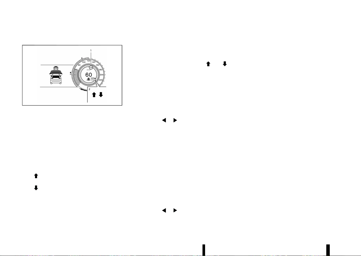
(326,1)
322 Starting and driving
System display and indicators:
MWAF1253X
Example
1. Detected speed limit indicator
Displays the currently detected speed limit. For
additional information, see “Traffic Sign Re-
cognition (TSR)” (P.271).
Applied speed limit indicator (green frame)
Indicates the detected speed limit can be
applied to the vehicle set speed.
2. Speed Limit Link indicator
Indicates the system operation.
“
” : Manual mode is activated and a new
speed limit (faster speed value) is indicated.
“
” : Manual mode is activated and a new
speed limit (lower speed value) is indicated.
Operating the system:
When the system detects a different speed limit,
the new speed value is indicated. The vehicle set
speed can be changed to the indicated speed limit
manually.
* To accept the newly indicated speed limit,
operate the <RES+> switch (in case of speed
limit up) or <SET-> switch (in case of speed
limit down).
* The Speed Limit Link indicator (
or )
will turn off after approximately 15 seconds if
the <RES+> or <SET-> switch is not operated.
(The Speed Limit Link indicator can be turned
off immediately by operating the opposite
switch from the direction indicated by the
Speed Limit Link indicator.)
The system will not activate if a speed limit change
is not detected.
How to activate or deactivate the system:
1. Push the
button on the steering
wheel until [Settings] appears in the vehicle
information display, and push the scroll dial.
2. Use the scroll dial to select [Driver Assistance].
Then push the scroll dial.
3. Select [Speed Limit Link] and push the scroll
dial to turn the system on or off.
NOTE:
The system will retain current settings in the
vehicle information display even if the engine is
restarted.
Selecting Speed Link Offset:
It is possible to set whether the speed limit should
be accepted exactly, or with a tolerance of –10
km/h (-5 MPH) to +10 km/h (+5 MPH).
1. Push the
button on the steering
wheel until [Settings] appears in the vehicle
information display, and push the scroll dial.
2. Use the scroll dial to select [Driver Assistance].
Then push the scroll dial.
3. Select [Speed Link Offset] and push the scroll
dial to select tolerance value. (Select “OFF” to
turn off the function.)
NOTE:
The function will retain current settings in the
vehicle information display even if the engine is
restarted.
Automatic cancellation
MEVT33A1-92601FE1-E941-4DF2-B81B-45FAACC54216
A chime sounds under the following conditions
and the control is automatically cancelled.
* When the vehicle ahead is not detected and
your vehicle is travelling below the speed of 25
km/h (15 MPH)
* When the system judges the vehicle is at
standstill
* When the shift lever is not in the D (Drive)
position
* When the parking brake is applied
* When the VDC/ESP system is turned off
* When VDC/ESP (including the traction control
system) operates
* When distance measurement becomes im-
paired due to adhesion of dirt or obstruction
to the sensor
* When a wheel slips
* When the radar signal is temporarily inter-
rupted
* On repeated uphill and downhill roads

(327,1)
Vehicle-to-vehicle distance control mode limitations
MEVT33A1-A46C10C4-5F29-44AC-9BE3-504021ED551E
WARNING
Listed below are the system limitations for the
ICC system. Failure to operate the vehicle in
accordance with these system limitations
could result in serious injury or death.
* The system is primarily intended for use on
straight, dry, open roads with light traffic.
It is not advisable to use the system in city
traffic or congested areas.
* This system will not adapt automatically to
road conditions. This system should be
used in evenly flowing traffic. Do not use
the system on roads with sharp curves,
steep uphill and downhill, or on icy roads,
in heavy rain or in fog.
* As there is a performance limit to the
distance control function, never rely solely
on the ICC system. This system does not
correct careless, inattentive or absent-
minded driving, or overcome poor visibility
in rain, fog, or other bad weather. Decele-
rate the vehicle speed by depressing the
brake pedal, depending on the distance to
the vehicle ahead and the surrounding
circumstances in order to maintain a safe
distance between vehicles.
* Always pay attention to the operation of
the vehicle and be ready to manually
control the proper following distance. The
vehicle-to-vehicle distance control mode
of the ICC system may not be able to
maintain the selected distance between
vehicles (following distance) or selected
vehicle speed under some circumstances.
* The system may not detect the vehicle in
front of you in certain road or weather
conditions. To avoid accidents, never use
the ICC system under the following condi-
tions:
— On roads where the traffic is heavy or
there are sharp curves
— On slippery road surfaces such as on
ice or snow, etc.
— During bad weather (rain, fog, snow,
etc.)
— When rain, snow or dirt adhere to the
system sensor
— On steep downhill roads (the vehicle
may go beyond the set vehicle speed
and frequent braking may result in
overheating the brakes)
— On repeated uphill and downhill roads
— When traffic conditions make it diffi-
cult to keep a proper distance be-
tween vehicles because of frequent
acceleration or deceleration
— Interference by other radar sources
* In some road or traffic conditions, a vehicle
or object can unexpectedly come into the
sensor detection zone and cause auto-
matic braking. You may need to control the
distance from other vehicles using the
accelerator pedal. Always stay alert and
avoid using the ICC system when it is not
recommended in this section.
* Do not use the ICC system if you are towing
a trailer or other vehicle. The system may
not detect a vehicle ahead.
The radar sensor will not detect the following
objects:
* Stationary and slow moving vehicles
* Pedestrians or objects in the roadway
* Oncoming vehicles in the same lane
* Motorcycles travelling offset in the travel lane
The sensor generally detects the signals returned
from the vehicle ahead. Therefore, if the sensor
cannot detect the reflection from the vehicle
ahead, the ICC system may not maintain the
selected distance.
The following are some conditions in which the
sensor cannot detect the signals:
* When the snow or road spray from travelling
vehicles reduces the sensor’s visibility
* When excessively heavy baggage is loaded in
the rear seat or the luggage compartment of
your vehicle
* When your vehicle is towing a trailer, etc.
The ICC system is designed to automatically check
the sensor’s operation within the limitation of the
system. When the sensor is covered with dirt or is
obstructed, the system will automatically be can-
celled. If the sensor is covered with ice, a trans-
parent or translucent vinyl bag, etc., the ICC
system may not detect them. In these instances,
the vehicle-to-vehicle distance control mode may
Starting and driving 323
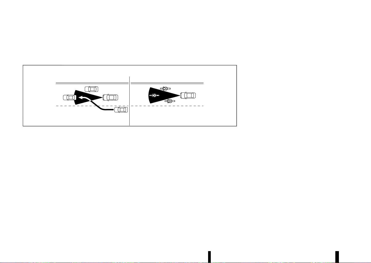
(328,1)
324 Starting and driving
not cancel and may not be able to maintain the
selected following distance from the vehicle
ahead. Be sure to check and clean the sensor
regularly.
MSSD0252
The detection zone of the radar sensor is limited. A
vehicle ahead must be in the detection zone for
the vehicle-to-vehicle distance detection mode to
maintain the selected distance from the vehicle
ahead.
A vehicle ahead may move outside of the detec-
tion zone due to its position within the same lane
of travel. Motorcycles may not be detected in the
same lane ahead if they are travelling offset from
the centerline of the lane. A vehicle that is entering
the lane ahead may not be detected until the
vehicle has completely moved into the lane. If this
occurs, the ICC system may warn you by blinking
the system indicator and sounding the chime.
The driver may have to manually control the
proper distance away from vehicle travelling
ahead.
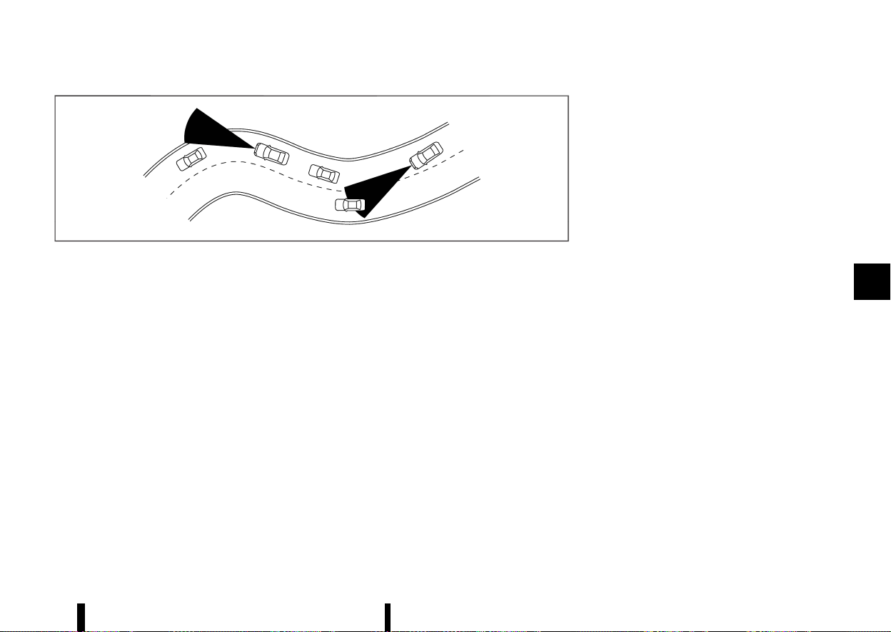
(329,1)
MSSD0253
When driving on some roads, such as winding, hilly,
curved, narrow roads, or roads which are under
construction, the radar sensor may detect vehicles
in a different lane, or may temporarily not detect a
vehicle travelling ahead. This may cause the ICC
system to decelerate or accelerate the vehicle.
The detection of vehicles may also be affected by
vehicle operation (steering manoeuvre or travel-
ling position in the lane, etc.) or vehicle condition. If
this occurs, the ICC system may warn you by
blinking the system indicator and sounding the
chime unexpectedly. You will have to manually
control the proper distance away from the
vehicle travelling ahead.
System temporarily unavailable
MEVT33A1-85942FC1-E434-4949-86A0-E9E0A1A9A03F
The following are conditions in which the ICC
system may be temporarily unavailable. In these
instances, the ICC system may not cancel and may
not be able to maintain the selected following
distance from the vehicle ahead.
Condition A:
Under the following conditions, the ICC system is
automatically cancelled. A chime will sound and
the system will not be able to be set:
* When the VDC/ESP is turned off
* When the VDC/ESP (including the traction
control system) operates
* When a vehicle ahead is not detected and your
vehicle is travelling below the speed of 25
km/h (15 MPH)
* When the system judges the vehicle is at a
standstill
* When the shift lever is not in the D (Drive)
position
* When the parking brake is applied
* When a tyre slips
* When the radar signal is temporarily inter-
rupted
* When any door is open
* On repeated uphill and downhill roads
Action to take:
When the conditions listed above are no longer
present, turn the ICC system back on to use the
system.
Condition B:
The chime will sound and the [Temporarily Dis-
abled Front Radar Blocked] warning message will
appear in the vehicle information display.
* When the radar sensor area is covered with
dirt or is obstructed, or the front radar is
impaired due to dirt or another obstruction
blocking the radar sensor, making it impossi-
ble to detect a vehicle ahead, the ICC system is
automatically cancelled.
Action to take:
If the warning message appears, stop the vehicle
in a safe place, push the park button to engage the
P (Park) position, and turn the engine off. When the
radar signal is temporarily interrupted, clean the
sensor area and restart the engine. If the [Tem-
porarily Disabled Front Radar Blocked] warning
message continues to be displayed, have the ICC
system checked by a NISSAN dealer or qualified
workshop.
* When driving on roads with limited road
structures or buildings (for example, long
bridges, deserts, snow fields, driving next to
long walls), the system may display the [Tem-
porarily Disabled Front Radar Blocked] warn-
ing message in the vehicle information display.
Action to take:
When the conditions listed above are no longer
Starting and driving 325
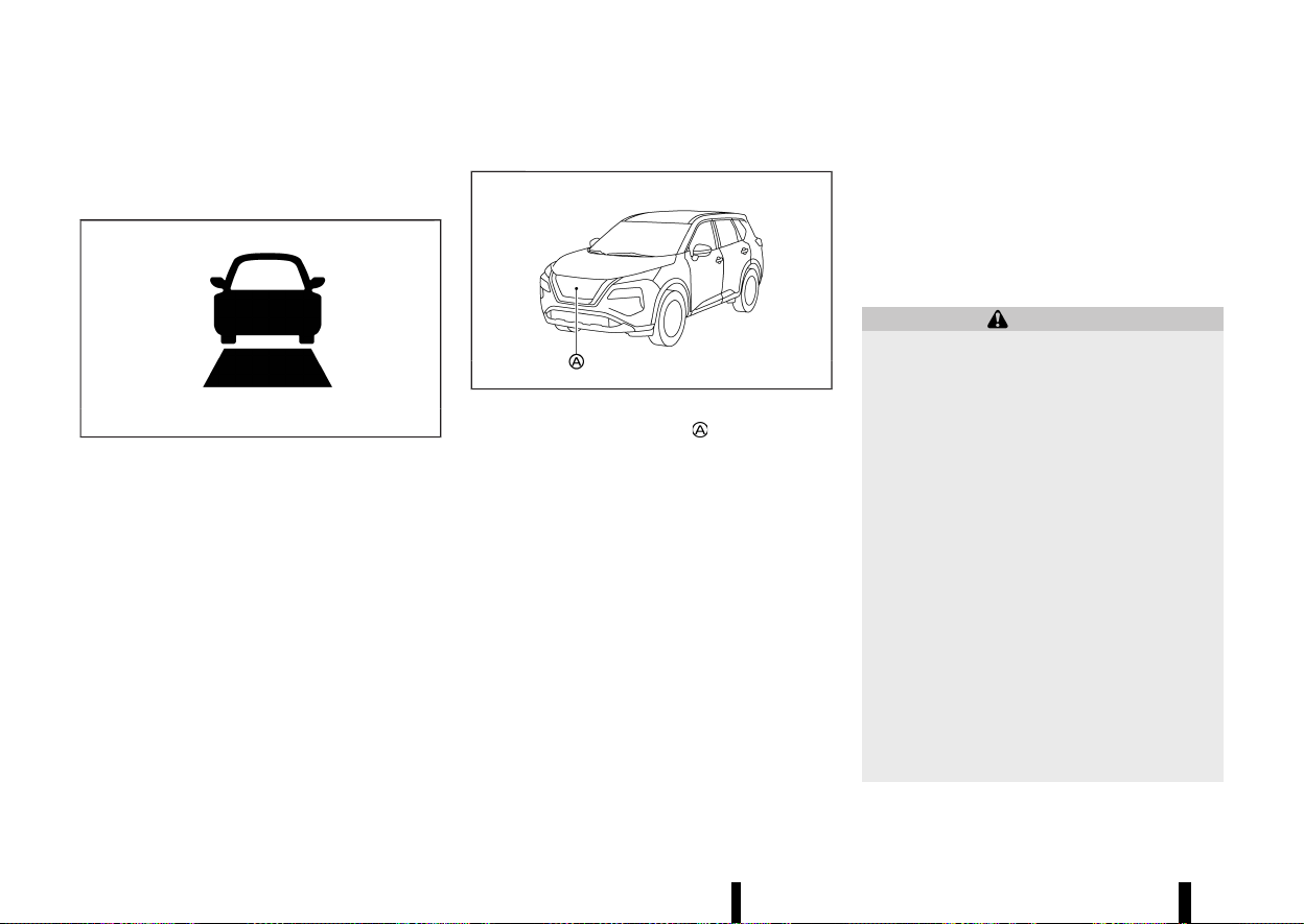
(330,1)
326 Starting and driving
present, turn the ICC system back on to use the
system.
System malfunction
MEVT33A1-D14DF48B-35B7-48BB-8788-E20978E07CE4
MJVS0968X
When the ICC system is not operating properly, the
chime sounds and the ICC system warning (yellow)
and the [System fault See Owner’s Manual] warn-
ing message will appear.
Action to take:
If the warning appears, push the park button to
shift to the P (Park) position, turn the engine off,
restart the engine, resume driving, and set the ICC
system again.
If it is not possible to set the system or the
warning stays on, it may indicate that the ICC
system is malfunctioning. Although the vehicle
is still driveable under normal conditions, have
the vehicle checked. See a NISSAN dealer or
qualified workshop for this service.
System maintenance
MEVT33A1-9522FD09-B2CC-4161-A587-97B806688345
MWAF0646X
The sensor for the ICC system is located on the
front of the vehicle.
To keep the ICC system operating properly, be sure
to observe the following:
* Always keep the sensor area clean.
* Do not strike or damage the areas around the
sensor.
* Do not cover or attach stickers or similar
objects near the sensor area. This could cause
failure or malfunction.
* Do not attach metallic objects near the sensor
area (brush guard, etc.). This could cause
failure or malfunction.
* Do not alter, remove or paint the front bumper.
Contact a NISSAN dealer or qualified workshop
before customising or restoring the front
bumper.
For the radio approval numbers and information,
see “Radio approval number and information”
(P.465).
CONVENTIONAL (fixed speed) CRUISE
CONTROL MODE
MEVT33A1-38B68700-2835-4BF5-809B-BFF0355304F5
This mode allows driving at a speed between 30 to
180 km/h (20 to 112 MPH) without keeping your
foot on the accelerator pedal.
WARNING
* In the conventional (fixed speed) cruise
control mode, a warning chime does not
sound to warn you if you are too close to
the vehicle ahead, as neither the presence
of the vehicle ahead nor the vehicle-to-
vehicle distance is detected.
* Pay special attention to the distance be-
tween your vehicle and the vehicle ahead
of you or a collision could occur.
* Always confirm the setting in the ICC
system display.
* Do not use the conventional (fixed speed)
cruise control mode when driving under
the following conditions:
— When it is not possible to keep the
vehicle at a set speed
— In heavy traffic or in traffic that varies
in speed
— On winding or hilly roads
— On slippery roads (rain, snow, ice, etc.)
— In very windy areas
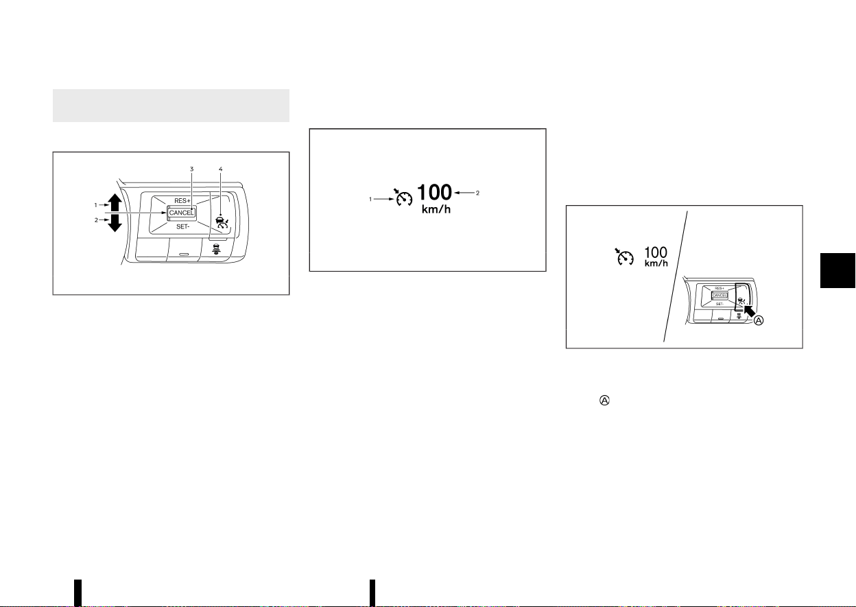
(331,1)
* Doing so could cause a loss of vehicle
control and result in an accident.
Conventional (fixed speed) CRUISE CONTROL SWITCHES
MEVT33A1-F564AAF8-8DCA-4EAB-9171-A05BDB7FF67B
MWAF1203X
1. <RES+> switch:
Resumes vehicle set speed or increases speed
incrementally
2. <SET-> switch:
Sets desired cruise speed or reduces speed
incrementally
3. <CANCEL> switch:
Deactivates the system without erasing the
vehicle set speed
4. Cruise ON/OFF switch:
Main switch to activate or deactivate the
system
Conventional (fixed speed) CRUISE CON-
TROL MODE DISPLAY AND INDICATORS
MEVT33A1-AEE0E379-8844-4C57-9B3E-5E7627AEE38F
MJVS0317X
The display is located in the vehicle information
display.
1. Cruise indicator:
This indicator indicates the condition of the
conventional (fixed speed) cruise control mode
of the ICC system depending on a colour.
.
Cruise control ON indicator (grey): Indicates
that the Cruise ON/OFF switch is on
.
Cruise control SET indicator (green): Indi-
cates that the cruising speed is set
.
Cruise control warning (yellow): Indicates
that there is a malfunction in the conven-
tional (fixed speed) cruise control mode of
the ICC system
2. Vehicle set speed indicator:
This indicator indicates the vehicle set speed.
.
Green: Cruise control active
.
Grey: Cruise control standby
(The speed unit can be converted between
“km/h” and "MPH". See “[Unit/Language]”
(P.89).)
Operating conventional (fixed speed)
CRUISE CONTROL MODE
MEVT33A1-C00C3601-DEA9-4DF5-9339-95E1BDCA4CA7
MWAF1204X
To turn on the conventional (fixed speed) cruise
control mode, push and hold the Cruise ON/OFF
switch
for longer than about 1.5 seconds.
When pushing the Cruise ON/OFF switch on, the
conventional (fixed speed) cruise control mode
display and indicators are displayed in the vehicle
information display. After you hold the Cruise ON/
OFF switch on for longer than about 1.5 seconds,
the ICC system display turns off. The cruise
indicator appears. You can now set your desired
cruising speed. Pushing the Cruise ON/OFF switch
again will turn the system completely off. When the
Starting and driving 327
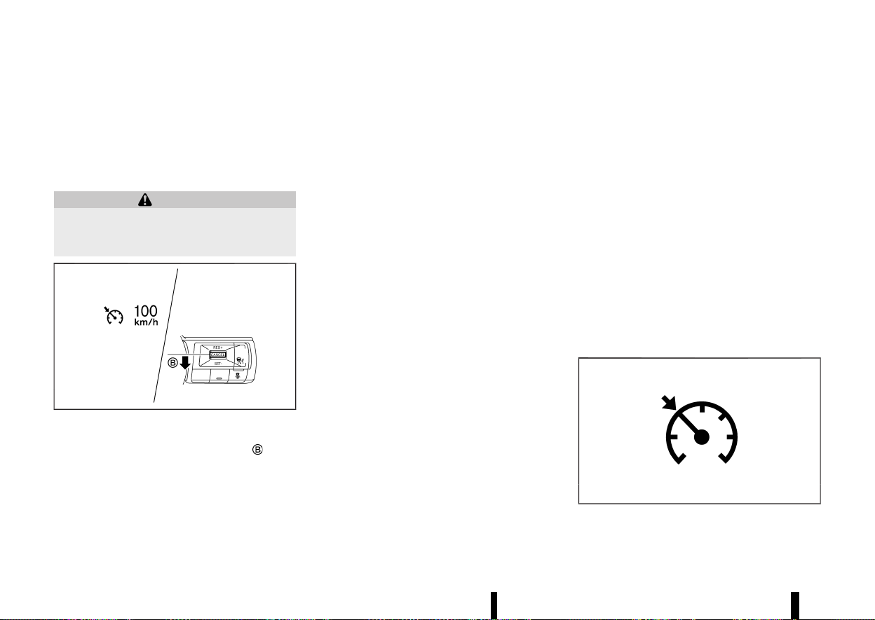
(332,1)
328 Starting and driving
ignition switch is placed in the “OFF” position, the
system is also automatically turned off.
To use the ICC system again, quickly push and
release the Cruise ON/OFF switch (vehicle-to-
vehicle distance control mode) or push and hold
it (conventional cruise control mode) again to turn
it on.
WARNING
To avoid accidentally engaging cruise control,
make sure to turn the Cruise ON/OFF switch off
when not using the ICC system.
MWAF1205X
To set cruising speed, accelerate your vehicle to
the desired speed, push down the <SET->
switch
and release it. (The colour of the cruise indicator
changes to green and vehicle set speed indicator
comes on.) Take your foot off the accelerator
pedal. Your vehicle will maintain the set speed.
* To pass another vehicle, depress the accel-
erator pedal. When you release the pedal, the
vehicle will return to the previously set speed.
* The vehicle may not maintain the set speed
when going up or down steep hills. If this
happens, manually maintain vehicle speed.
To cancel the preset vehicle speed, use any of the
following methods:
* Push the <CANCEL> switch. The vehicle set
speed indicator and the cruise indicator will
turn grey.
* Tap the brake pedal. The vehicle set speed
indicator and the cruise indicator will turn
grey.
* Turn the Cruise ON/OFF switch off. Both the
cruise indicator and vehicle set speed indica-
tor will turn off.
To reset at a faster cruising speed, use one of the
following three methods:
* Depress the accelerator pedal. When the
vehicle attains the desired speed, push down
and release the <SET-> switch.
* Push up and hold the <RES+> switch. When the
vehicle attains the desired speed, release the
switch.
* Push up, then quickly release the <RES+>
switch. Each time you do this, the vehicle set
speed will increase by about 1 km/h (1 MPH).
To reset at a slower cruising speed, use one of the
following three methods:
* Lightly tap the brake pedal. When the vehicle
attains the desired speed, push down the
<SET-> switch and release it.
* Push down and hold the <SET-> switch.
Release the switch when the vehicle slows
down to the desired speed.
* Push down, then quickly release the <SET->
switch. Each time you do this, the vehicle set
speed will decrease by about 1 km/h (1 MPH).
To resume the preset vehicle speed, push up and
release the <RES+> switch. The vehicle will resume
the last set cruising speed when the vehicle speed
is over 30 km/h (20 MPH).
System temporarily unavailable
MEVT33A1-5B2B525E-C698-43A3-BE9C-01230B5A3711
A chime sounds under the following conditions
and the control is automatically cancelled.
* When the shift lever is not in the D (Drive)
position
* When the parking brake is applied
* When the VDC/ESP system (including the
traction control system) operates
* When the VDC/ESP system is turned off
* When a wheel slips
Warning
MJVS1003X
When the system is not operating properly, the

(333,1)
chime sounds and the colour of the cruise
indicator will change to yellow.
Action to take:
If the colour of the cruise indicator changes to
yellow, park the vehicle in a safe place. Turn the
engine off, restart the engine, resume driving and
then perform the setting again.
If it is not possible to set or the indicator stays
on, it may indicate that the system is malfunc-
tioning. Although the vehicle is still driveable
under normal conditions, have the system
checked. It is recommended you visit a NISSAN
dealer or qualified workshop for this service.
MEVT33A1-D0EE6AF6-52E3-4B00-ABAC-0191D4A752CC
WARNING
Failure to follow the warnings and instructions
for proper use of the ProPILOT Assist system
could result in serious injury or death.
* ProPILOT Assist is not a self-driving sys-
tem. Within the limits of its capabilities, as
described in this manual, it helps the driver
with certain driving activities.
* The ProPILOT Assist system is not a repla-
cement for proper driving procedures and
is not designed to correct careless, inat-
tentive or absent-minded driving. ProPI-
LOT Assist will not always steer the vehicle
to keep it in the lane. The ProPILOT Assist
system is not designed to prevent loss of
control. It is the driver’s responsibility to
stay alert, drive safely, keep the vehicle in
the travelling lane, and be in control of the
vehicle at all times.
* There are limitations to the ProPILOT
Assist system capability. The ProPILOT
Assist system does not function in all
driving, traffic, weather, and road condi-
tions. It is the driver’s responsibility to stay
alert, drive safely, keep the vehicle in the
travelling lane, and be in control of the
vehicle at all times.
* The ProPILOT Assist system is only an aid
to assist the driver and is not a collision
warning or avoidance device.
* The ProPILOT Assist system is for use on
highways with opposing traffic separated
by a barrier only, and is not intended for
city driving. Failure to apply the brakes or
steer the vehicle when necessary may
result in a serious accident.
* Always observe posted speed limits and do
not set the speed over them.
* Never take your hands off the steering
wheel when driving. Always keep your
hands on the steering wheel and drive
your vehicle safely.
* Never unfasten your safety belt when
using ProPILOT Assist. Doing so automati-
cally cancels the ProPILOT Assist system.
* The ProPILOT Assist system does not react
when approaching stationary or slow mov-
ing vehicles.
* Always drive carefully and attentively
when using the ProPILOT Assist system.
Read and understand the Owner’s Manual
thoroughly before using the ProPILOT As-
sist system. To avoid serious injury or
death, do not rely on the system to prevent
accidents or to control the vehicle’s speed
in emergency situations. Do not use the
ProPILOT Assist system except in appro-
priate road and traffic conditions.
Starting and driving 329
PROPILOT ASSIST (where fitted)
PROPILOT ASSIST (where fitted)
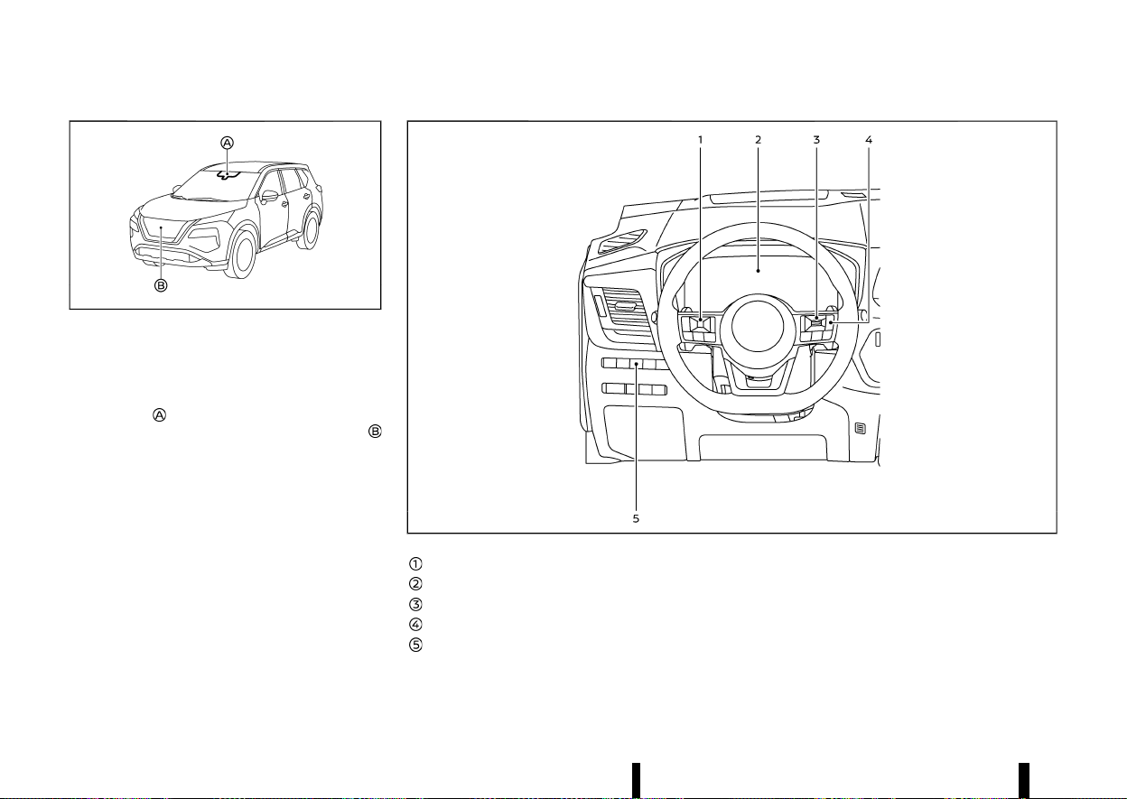
(334,1)
330 Starting and driving
MWAF0644X
The ProPILOT Assist system is intended to en-
hance the operation of the vehicle when following
a vehicle travelling in the same lane and direction.
The ProPILOT Assist system uses a multi-sensing
front camera
installed behind the windscreen to
monitor the lane markers and a radar sensor
located on the front of the vehicle to measure the
distance to the vehicle ahead in the same lane. If
the system detects a slower moving vehicle ahead,
the system will reduce the vehicle speed so that
your vehicle follows the vehicle in front at the
selected distance. The system will also help keep
the vehicle centered in the travelling lane when
clear lane markings are detected.
NOTE:
It is important to ensure the front camera and
radar sensors are clear at all times. (See “ICC
sensor maintenance” (P.351) and “Steering Assist
maintenance” (P.356) for more details.)
MWAF0557X
Steering-wheel-mounted control (left)
Vehicle information display
Steering-wheel-mounted control (right)
ProPILOT Assist switch
Steering Assist switch
PROPILOT ASSIST SYSTEM OPERATION
MEVT33A1-F2D7746A-1B14-4D83-AF41-9BEB5EB544EB
The ProPILOT Assist system has the following two
functions:
1. Intelligent Cruise Control (ICC)
MEVT33A1-4AE536C9-D3DA-4310-AF97-2C293D4005CF
The ICC system can be set to one of two cruise
control modes:

(335,1)
* Conventional (fixed speed) cruise control
mode:
For cruising at a preset vehicle speed
For additional information, see “Turning the con-
ventional (fixed speed) cruise control mode ON”
(P.334).
NOTE:
Steering Assist is not available in the conven-
tional (fixed speed) cruise control mode.
* Vehicle-to-vehicle distance control mode:
The ICC system maintains a selected distance
from the vehicle in front of you within the
speed range of 0 km/h (0 MPH) up to the
vehicle set speed. The vehicle set speed can be
selected by the driver above approximately 30
km/h (20 MPH). When the vehicle ahead slows
to a stop, your vehicle gradually decelerates to
a standstill. When the vehicle is stopped, the
ICC system maintains braking force to keep
your vehicle stationary.
* When your vehicle is stopped for less than
approximately 3 seconds and the vehicle
ahead begins to move, your vehicle will start
moving again automatically. If your vehicle is
stationary for more than approximately 3
minutes, the ICC system will be switched off
and the electronic parking brake will be
applied.
* When the vehicle ahead begins to move
forward, push up the <RES+> switch on the
steering wheel or lightly depress the accel-
erator pedal to release the brake. The ICC
system will restart to maintain a selected
distance from the vehicle in front of you.
* Always check surroundings before restarting
the vehicle.
* When stationary and no vehicle is detected
ahead, the ICC system will not function. The
accelerator pedal should be used to control
the vehicle speed.
NOTE:
Even if the Intelligent Emergency Braking
setting is turned off by the driver using the
[Settings] menu in the vehicle information dis-
play, Intelligent Emergency Braking will be
automatically turned on when ICC is used.
2. Steering Assist
MEVT33A1-1DA108D7-F64C-4012-9215-337BCD65A695
The Steering Assist function controls the steering
system to help keep your vehicle within the
travelling lane.
When there is no vehicle ahead, Steering Assist is
not available at speeds under 60 km/h (37 MPH).
Starting and driving 331
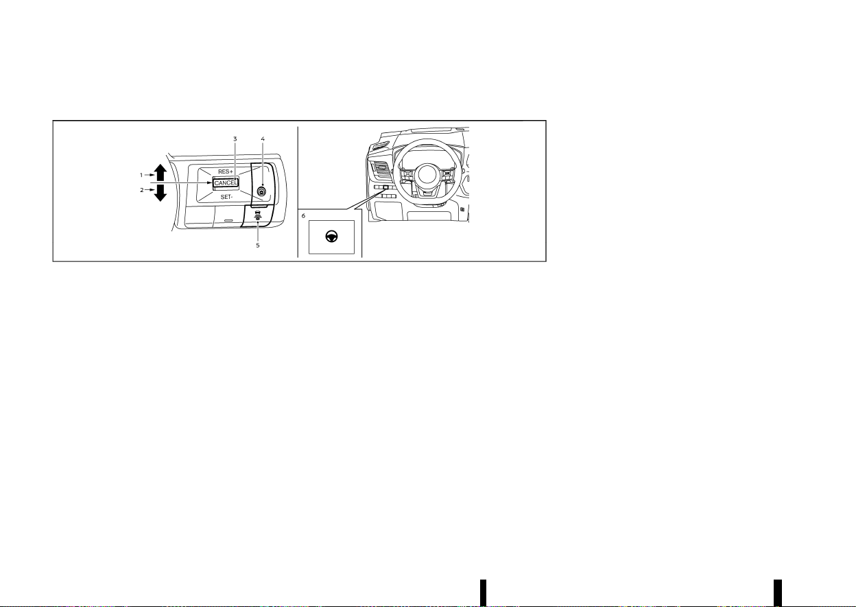
(336,1)
332 Starting and driving
PROPILOT ASSIST SWITCHES
MEVT33A1-E745EA52-7201-4F16-83B5-BAB0DFEE2CAC
MWAF0422X
1. <RES+> switch:
Resumes vehicle set speed or increases speed
incrementally
2. <SET-> switch:
Sets desired cruise speed or reduces speed
incrementally
3. <CANCEL> switch:
Deactivates the ProPILOT Assist system with-
out erasing the set speed
4. ProPILOT Assist switch:
Turns the ProPILOT Assist system on or off
5. DISTANCE switch:
.
[Far]
.
[Middle]
.
[Short]
6. Steering Assist switch:
Turns the Steering Assist function on or off
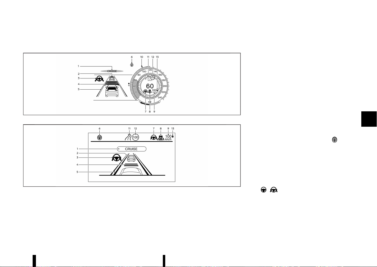
(337,1)
PROPILOT ASSIST SYSTEM DISPLAY AND INDICATORS
MEVT33A1-F06E4F2F-FE49-438F-B3E5-1CA14DC2A0B8
MWAF1170X
Models with full-screen display
MWAF1175X
Models with analog meter and colour display
1. ProPILOT Assist activation
Displays once the ProPILOT Assist system is
activated
2. Vehicle ahead detection indicator
Displays whether the system detects a vehicle
in front of you (only when ICC is active)
3. Steering Assist indicator
Indicates the status of the Steering Assist
function by the colour of the indicator
.
Steering Assist indicator (grey): Steering
Assist standby
.
Steering Assist indicator (green): Steering
Assist active
4. Set distance indicator
Displays the selected distance
5. Lane marker indicator
Indicates whether the system detects lane
markers
.
No lane markers displayed: Steering Assist is
turned off
.
Lane marker indicator (grey): No lane mar-
kers detected
.
Lane marker indicator (green): Lane mar-
kers detected, Steering Assist is active
.
Lane marker indicator (yellow): Lane depar-
ture is detected
6. ProPILOT Assist status indicator (
)
Indicates the status of the ProPILOT Assist
system by the colour of the indicator
.
ProPILOT Assist status indicator (white):
ProPILOT Assist is on but in standby
.
ProPILOT Assist status indicator (blue): Pro-
PILOT Assist active
7. Steering Assist status indicator/warning
(
, )
Displays the status of the Steering Assist by
the colour of the indicator/warning
.
No Steering Assist status indicator dis-
played: Steering Assist is turned off
.
Steering Assist status indicator (grey):
Steering Assist standby
Starting and driving 333
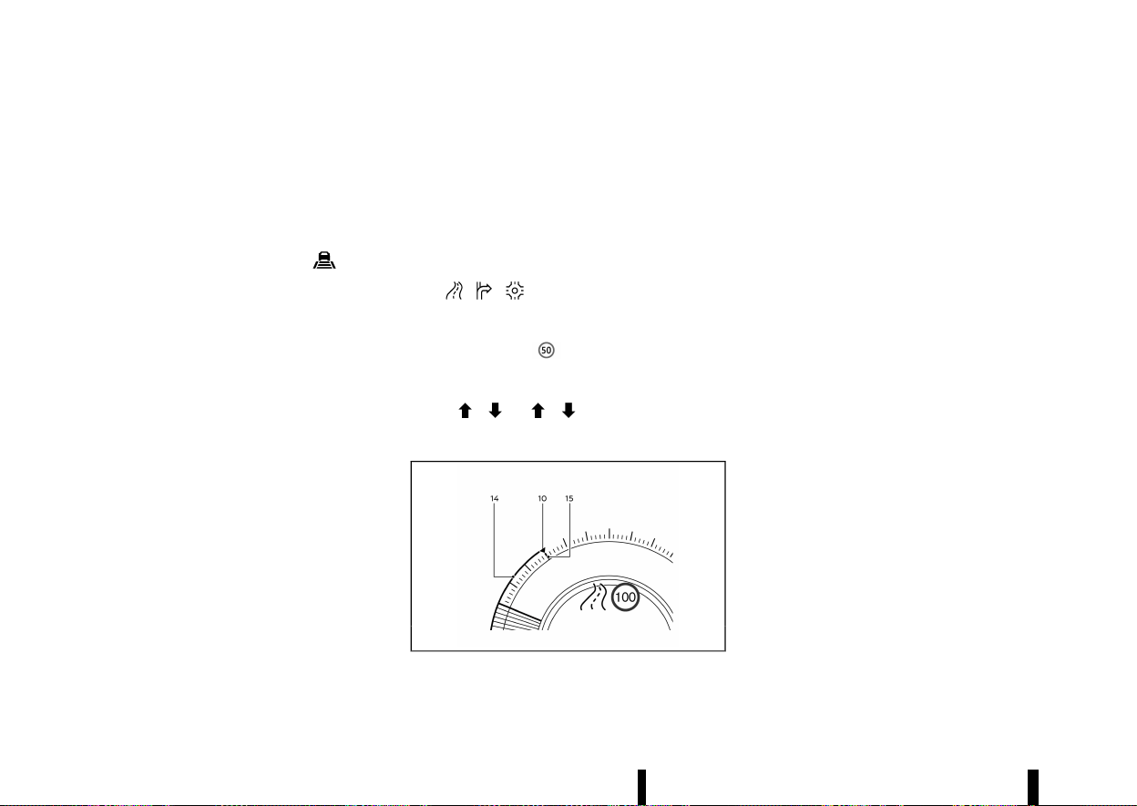
(338,1)
334 Starting and driving
.
Steering Assist status indicator (green):
Steering Assist active
.
Steering Assist status indicator (yellow):
Steering Assist malfunction
.
Steering Assist status indicator (red): Hands
off detected
8. Speed control status indicator/set distance
indicator/lane marker indicator (
)
Displays the status of speed control by the
colour of the indicator, and displays the
selected distance by the number of horizontal
bars shown
.
Speed control status indicator (white): ICC
standby
.
Speed control status indicator (green): ICC
(distance control mode) is active
— Green vehicle icon displayed: Vehicle
detected ahead
— No vehicle icon shown: No vehicle de-
tected ahead (Your vehicle maintains
the driver-selected set speed.)
.
Speed control status indicator (yellow): In-
dicates an ICC malfunction
For the lane marker indicator, see “Steering
Assist display and indicators” (P.352).
9. Vehicle set speed indicator
Indicates the vehicle set speed
.
Green: ICC active
.
Grey: ICC standby
(The speed unit can be converted between
[km/h] and [MPH]. See “[Unit/Language]”
(P.89).)
10. Target speed indicator (where fitted)
Indicates the target vehicle speed
.
White triangle: Cruise control or speed
limiter (where fitted) target speed
.
Green triangle: ICC target speed
11. Road information indicator (where fitted)
(
, , )
Indicates the detected road information
12. Detected road sign (speed limit) indicator
(where fitted) (
)
Indicates the currently detected speed limit
13. Speed Limit Link indicator (where fitted)
(A,
, / , )
Indicates the Speed Limit Link activation mode
or system operation
MWAF1247X
14. Green line (where fitted)
Indicates a gap between the current speed
and the ICC target speed
15. Red line (where fitted)
Indicates the Traffic Sign Recognition (TSR)
speed limit marker
NOTE:
* Some of the items listed above are only
available in classic view (models with full-
screen display), shown in the illustration
above. (See “Changing the meter screen
view (models with full-screen display)”
(P.69).)
* When the ProPILOT Assist system is acti-
vated, the display will automatically be
switched to the ProPILOT Assist system
display. To disable this function, turn [AUTO
Cruise Display] off under [Display Settings]
of the settings menu.
The ProPILOT Assist display is also shown in the
Head Up Display (HUD) (where fitted). (See “[Head
Up Display (HUD)] (where fitted)” (P.105).)
TURNING THE CONVENTIONAL (fixed
speed) CRUISE CONTROL MODE ON
MEVT33A1-C086B46A-991B-4F15-AF11-314FCEBBE829
NOTE:
ProPILOT Assist provides no approach warnings,
automatic braking, or Steering Assist in the
conventional (fixed speed) cruise control mode.
To choose the conventional (fixed speed) cruise
control mode, push and hold the ProPILOT Assist
switch for longer than approximately 1.5 seconds.
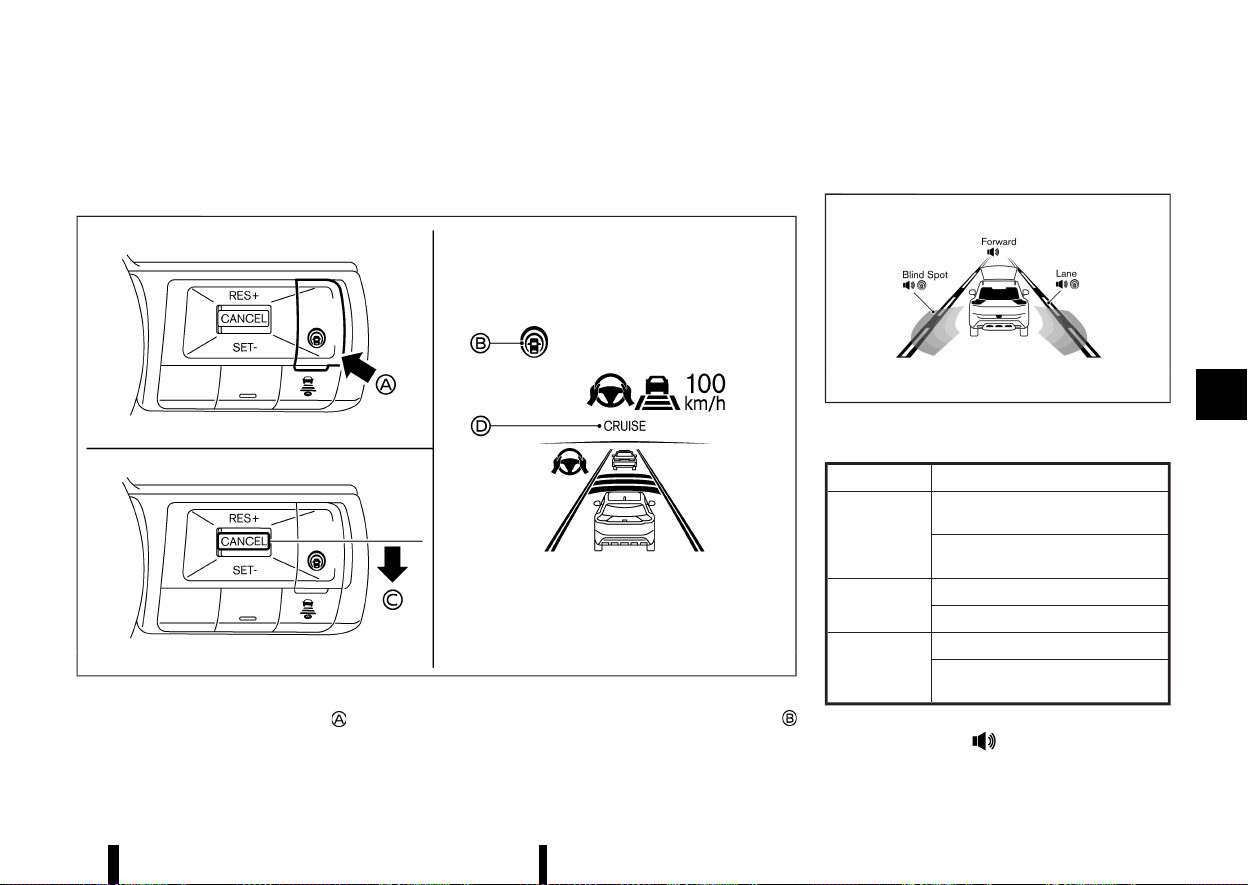
(339,1)
For additional information, see “Conventional (fixed
speed) cruise control mode” (P.356).
OPERATING PROPILOT ASSIST
MEVT33A1-EDDA12BB-8CB2-4CC2-A232-C5C5C371723C
MWAF0843X
Example
1. Push the ProPILOT Assist switch . This turns
on the ProPILOT Assist system.
.
The ProPILOT Assist status indicator
illuminates in white.
.
A screen is displayed for a period of time
that indicates the status of the Driving Aid
functions.
MWAF1248X
Example (all enabled)
When the Driving Aids are enabled:
Zone
Driving Aid
Forward
Intelligent Emergency Braking with
Pedestrian Detection
Intelligent Forward Collision Warn-
ing
Lane
Lane Departure Warning (LDW)
Intelligent Lane Intervention
Blind Spot
Blind Spot Warning (BSW)
Intelligent Blind Spot Intervention
(where fitted)
.
When any of the ‘Warning’ systems are
enabled, the “
” mark is shown in each
zone.
Starting and driving 335
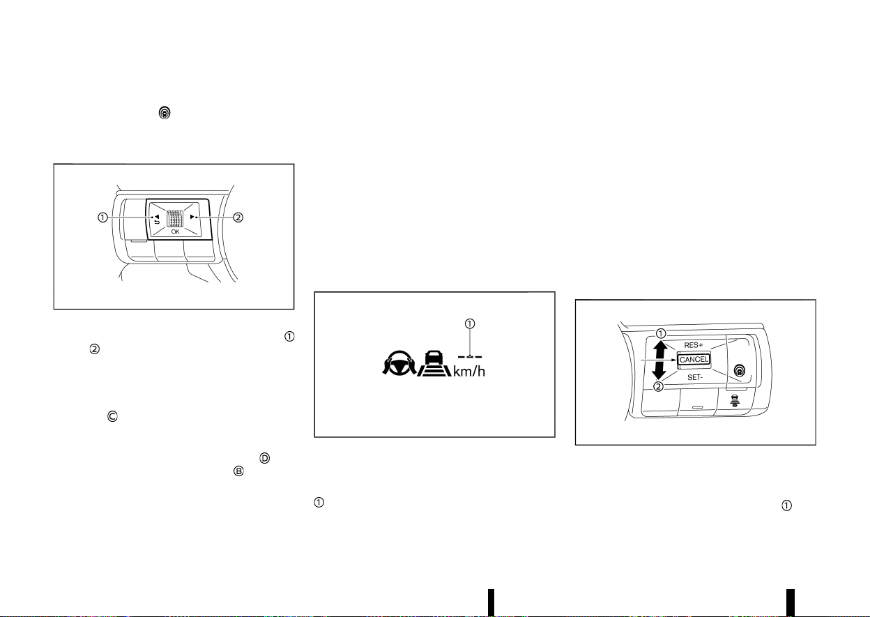
(340,1)
336 Starting and driving
.
When any of the “Intervention” systems are
enabled, the “
” mark is shown in each
zone.
.
When no system is enabled, “OFF” is shown
in each zone.
MWAF0560X
To change the status of the Driving Aids, use
or to navigate the settings screen. For
additional information, see “How to use the
vehicle information display” (P.82).
2. Accelerate or decelerate your vehicle to the
desired speed and push down the <SET->
switch
.
The ProPILOT Assist system begins to auto-
matically maintain the vehicle set speed. The
ProPILOT Assist activation indicator
and
ProPILOT Assist status indicator
illuminate
in blue. When a vehicle ahead is detected and
travelling at a speed of 30 km/h (20 MPH) or
below and the <SET-> switch is pushed down,
the vehicle set speed is 30 km/h (20 MPH).
NOTE:
When the Intelligent Lane Intervention system
and Intelligent Blind Spot Intervention system
(where fitted) are enabled in the settings menu
of the vehicle information display, turning the
ProPILOT Assist system on will turn on these
systems at the same time. If the Intelligent Lane
Intervention system is disabled In the settings
menu, the Intelligent Lane Intervention system
will automatically be turned on when the Steer-
ing Assist system is active. For additional in-
formation, see “Intelligent Lane Intervention
(where fitted)” (P.277), “Intelligent Lane Interven-
tion” (P.353) and “Intelligent Blind Spot Interven-
tion (where fitted)” (P.295).
MWAF0844X
When the <SET-> switch is pushed down under the
following conditions, the ProPILOT Assist system
cannot be set and the vehicle set speed indicator
blinks for approximately 2 seconds:
* When travelling below 30 km/h (20 MPH) and a
vehicle ahead is not detected
* When the shift lever is moved out of the D
(Drive) position or into the manual shift mode
* When the parking brake is applied
* When the brakes are operated by the driver
* When the VDC/ESP system is off. For additional
information, see “Vehicle Dynamic Control
(VDC)/Electronic Stability Programme (ESP)
system” (P.391).
* When the VDC/ESP system (including the
traction control system) is activated
* When a wheel is slipping
* When any door is open
* When the driver’s seat belt is not fastened
How to change the vehicle set speed
MEVT33A1-ADF4F2BB-464E-4AA1-B832-ED61422A00C2
MWAF0561X
The vehicle set speed can be adjusted.
To change to a faster cruising speed:
* Push up and hold the <RES+> switch
. The
vehicle set speed increases in increments of 10
km/h or 5 MPH.
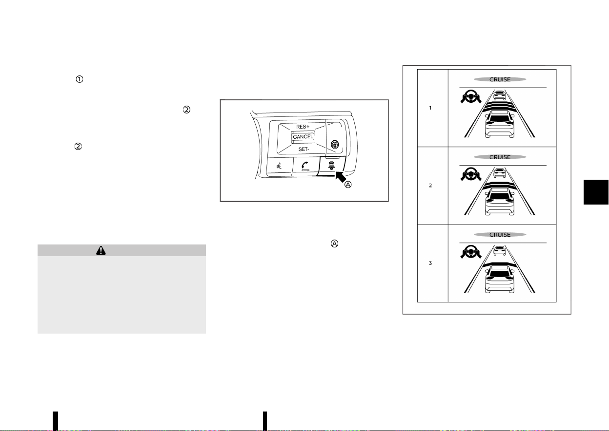
(341,1)
* Push up, then quickly release the <RES+>
switch
. Each time you do this, the vehicle
set speed increases by 1 km/h (1 MPH).
To change to a slower cruising speed:
* Push down and hold the <SET-> switch
. The
vehicle set speed decreases in increments of
10 km/h or 5 MPH.
* Push down, then quickly release the <SET->
switch
. Each time you do this, the vehicle set
speed decreases by 1 km/h (1 MPH).
How to momentarily accelerate or decelerate
MEVT33A1-FB44C9A1-CA1B-406C-865A-89F2EDD739C4
* Depress the accelerator pedal when accelera-
tion is required. Release the accelerator pedal
to resume the previously set vehicle speed.
* Depress the brake pedal when deceleration is
required. Control by the ProPILOT Assist sys-
tem is cancelled. Push up the <RES+> switch to
resume the previously set vehicle speed.
WARNING
When the accelerator pedal is depressed and
you are approaching the vehicle ahead, the ICC
system will neither control the brake nor warn
the driver with the chime and display. The
driver must manually control the vehicle speed
to maintain a safe distance to the vehicle
ahead. Failure to do so could result in severe
personal injury or death.
NOTE:
When you accelerate by depressing the accel-
erator pedal or decelerate by pushing down the
<SET-> switch and the vehicle travels faster than
the speed set by the driver, the vehicle set speed
indicator will blink.
How to change the set distance to the vehicle ahead
MEVT33A1-4BF598EE-06EE-4494-916D-FE82903C53F4
MWAF0424X
Example
The distance to the vehicle ahead can be selected
at the time of the ICC standby or the ICC is active.
Each time the DISTANCE switch
is pushed, the
set distance will change to “long”, “middle”, “short”
and back to “long” again in that sequence.
MWAF0645X
Example
Distance — approximate distance at 100 km/h
(60 MPH)
1. Long – 60 m (200 ft)
Starting and driving 337
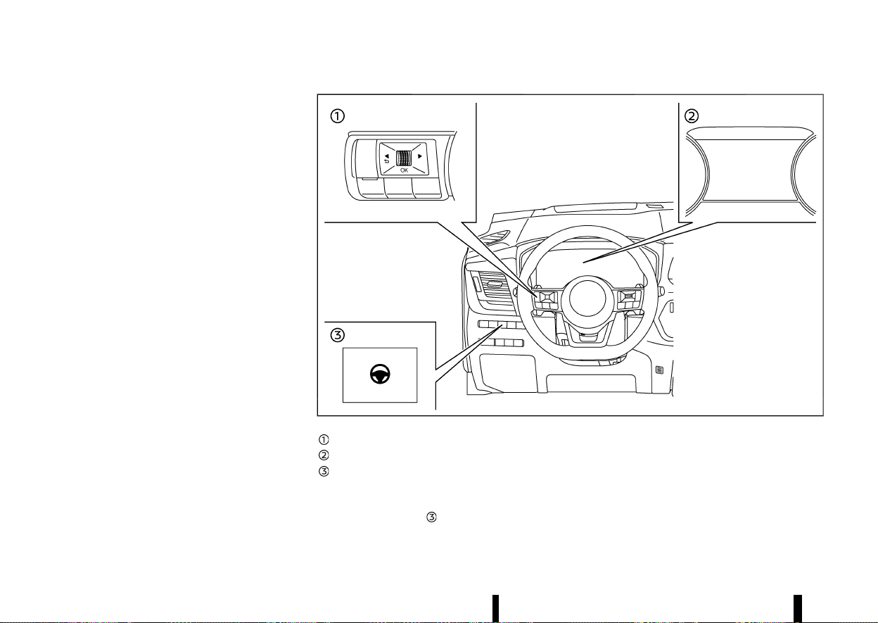
(342,1)
338 Starting and driving
2. Middle – 45 m (150 ft)
3. Short – 30 m (90 ft)
* The actual distance to the vehicle ahead
adjusts automatically according to the vehicle
speed. The higher the vehicle speed, the longer
the distance.
* The distance setting will remain at the current
setting even if the engine is restarted.
HOW TO ENABLE/DISABLE THE STEER-
ING ASSIST
MEVT33A1-26CF5DEC-8F62-4D9D-AE33-D29CC2EB19B8
Use the following methods to enable or disable the
Steering Assist.
MWAF0425X
Steering-wheel-mounted control (left)
Vehicle information display
Steering Assist switch
Steering Assist switch:
To turn the Steering Assist on or off, push the
Steering Assist switch
on the instrument panel.
NOTE:
* When the Steering Assist switch is used to
turn the system on or off, the system
remembers the setting even if the ignition
switch is cycled. The switch must be pushed
again to change the setting to on or off.
* The Steering Assist switch changes the
status of the [Steering Assist] selection

(343,1)
made in the [Settings] screen in the vehicle
information display.
Setting in the vehicle information display:
1. Push the
button on the steering
wheel
until [Settings] appears in the vehicle
information display
and then push the scroll
dial.
2. Use the scroll dial to select [Driver Assistance].
Then push the scroll dial.
3. Select [Steering Assist] and push the scroll dial
to turn the Steering Assist on or off.
NOTE:
* When the ProPILOT Assist screen is dis-
played on the vehicle information display,
push the scroll dial on the steering wheel to
call up the [Driver Assistance] setting dis-
play.
* When enabling/disabling the system
through the vehicle information display,
the system retains the current settings even
if the engine is restarted.
HOW TO CANCEL THE PROPILOT ASSIST
SYSTEM
MEVT33A1-5B367FD4-1289-4AE6-ACE5-9B8B750ED3F2
To cancel the ProPILOT Assist system, use one of
the following methods:
* Push the <CANCEL> switch.
* Tap the brake pedal (except at a standstill).
* Push the ProPILOT Assist switch to turn the
system off. The ProPILOT Assist status indica-
tor will turn off.
When the ProPILOT Assist system is cancelled
while the vehicle is stopped, the electronic parking
brake is automatically activated.
WARNING
To prevent the vehicle from moving or rolling
unexpectedly, which could result in serious
personal injury or property damage, before
exiting the vehicle make sure to push the
ProPILOT Assist switch to turn the system off,
push the park button to shift to the P (Park)
position, and turn the engine off.
INTELLIGENT CRUISE CONTROL (ICC)
MEVT33A1-FDF49E0A-D045-482C-9257-E9ED40B77913
* The Intelligent Cruise Control (ICC) is a part of
the ProPILOT Assist system. To choose the ICC
system without the Steering Assist, activate
the ProPILOT Assist and then turn off the
Steering Assist with the switch or in the
settings menu. For additional information,
see “Operating ProPILOT Assist” (P.335) and
“How to enable/disable the Steering Assist”
(P.338).
* To choose the conventional (fixed speed)
cruise control mode, push and hold the
ProPILOT Assist switch for longer than ap-
proximately 1.5 seconds. For additional infor-
mation, see “Conventional (fixed speed) cruise
control mode” (P.356).
WARNING
Failure to follow the warnings and instructions
for proper use of the ICC system could result in
serious injury or death.
* The ICC system is only an aid to assist the
driver and is not a collision warning or
avoidance device. It is recommended for
highway use only and it is not intended for
congested areas or city driving. It is the
driver’s responsibility to stay alert, drive
safely, and be in control of the vehicle at all
times.
* There are limitations to the ICC system
capability. The ICC system does not func-
tion in all driving, traffic, weather, and road
conditions. It is the driver’s responsibility
to stay alert, drive safely, keep the vehicle
in the travelling lane, and be in control of
the vehicle at all times.
* Always observe posted speed limits and do
not set the speed over them.
* The ICC system does not react to station-
ary or slow moving vehicles.
* Always drive carefully and attentively
when using the ICC system. Read and
understand the Owner’s Manual thor-
oughly before using the ICC system. To
avoid serious injury or death, do not rely on
the system to prevent accidents or to
control the vehicle’s speed in emergency
situations. Do not use the ICC system
except in appropriate road and traffic
conditions.
ICC system operation
MEVT33A1-03C3CF7D-C564-4F68-AC8D-95C5A712D760
The ICC system is designed to maintain a selected
distance from the vehicle in front of you and can
reduce the speed to match a slower vehicle ahead.
Starting and driving 339
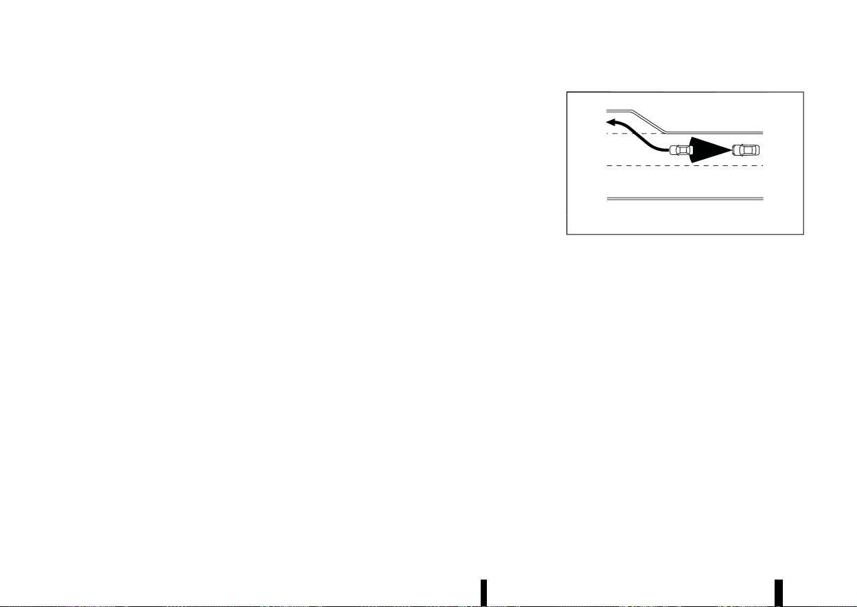
(344,1)
340 Starting and driving
The system decelerates the vehicle as necessary
and if the vehicle ahead comes to a stop, the
vehicle decelerates to a standstill. However, the ICC
system can only apply up to approximately 40% of
the vehicle’s total braking power.
This system should only be used when traffic
conditions allow vehicle speeds to remain fairly
constant or when vehicle speeds change gradu-
ally. If a vehicle moves into the travelling lane
ahead or if a vehicle travelling ahead rapidly
decelerates, the distance between vehicles may
become closer because the ICC system cannot
decelerate the vehicle quickly enough. If this
occurs, the ICC system sounds a warning chime
and blinks the system display to notify the driver to
take necessary action.
The ICC system cancels and a warning chime
sounds if the speed is below approximately 25
km/h (15 MPH) and a vehicle is not detected ahead.
The ICC system cancels and a warning chime
sounds if your vehicle is at a standstill for more
than approximately 3 seconds and a vehicle is not
detected ahead.
The ICC system operates as follows:
* When there are no vehicles travelling ahead,
the ICC system maintains the speed set by the
driver. The vehicle set speed range is above
approximately 30 km/h (20 MPH).
* When there is a vehicle travelling ahead, the
ICC system adjusts the speed to maintain the
distance, selected by the driver, from the
vehicle ahead. If the vehicle ahead comes to
a stop, the vehicle decelerates to a standstill.
Once your vehicle stops, the ICC system keeps
the vehicle stopped.
* When your vehicle is at a standstill for more
than 3 seconds and the vehicle ahead begins
to accelerate, push up the <RES+> switch or
lightly depress the accelerator pedal. The ICC
system starts to follow the vehicle ahead. If
your vehicle is stationary for more than
approximately 3 minutes, the ICC system will
be switched off and the electronic parking
brake will be applied.
* When the vehicle travelling ahead moves to a
different travelling lane, while the vehicle
speed is above 30 km/h (20 MPH), the ICC
system accelerates and maintains vehicle
speed up to the set speed.
* When the vehicle travelling ahead moves to a
different travelling lane, while the vehicle
speed is below 30 km/h (20 MPH), the ICC
system cancels and a warning chime sounds.
The ICC system does not control vehicle speed or
warn you when you approach stationary and slow
moving vehicles. You must pay attention to vehicle
operation to maintain proper distance from vehi-
cles ahead when approaching toll gates or traffic
congestion.
MSSD0254
When driving on the highway at a vehicle set speed
and approaching a slower travelling vehicle ahead,
the ICC system adjusts the speed to maintain the
distance, selected by the driver, from the vehicle
ahead. If the vehicle ahead changes lanes or exits
the highway, the ICC system accelerates and
maintains the vehicle set speed. Pay attention to
the driving operation to maintain control of the
vehicle as it accelerates to the set speed.
The vehicle may not maintain the set speed on
winding or hilly roads. If this occurs, you will have
to manually control the vehicle speed.
Normally when controlling the distance to a
vehicle ahead, the system automatically acceler-
ates or decelerates your vehicle according to the
speed of the vehicle ahead.
Depress the accelerator to properly accelerate
your vehicle when acceleration is required for a
lane change. Depress the brake pedal when
deceleration is required to maintain a safe dis-
tance to the vehicle ahead due to sudden braking
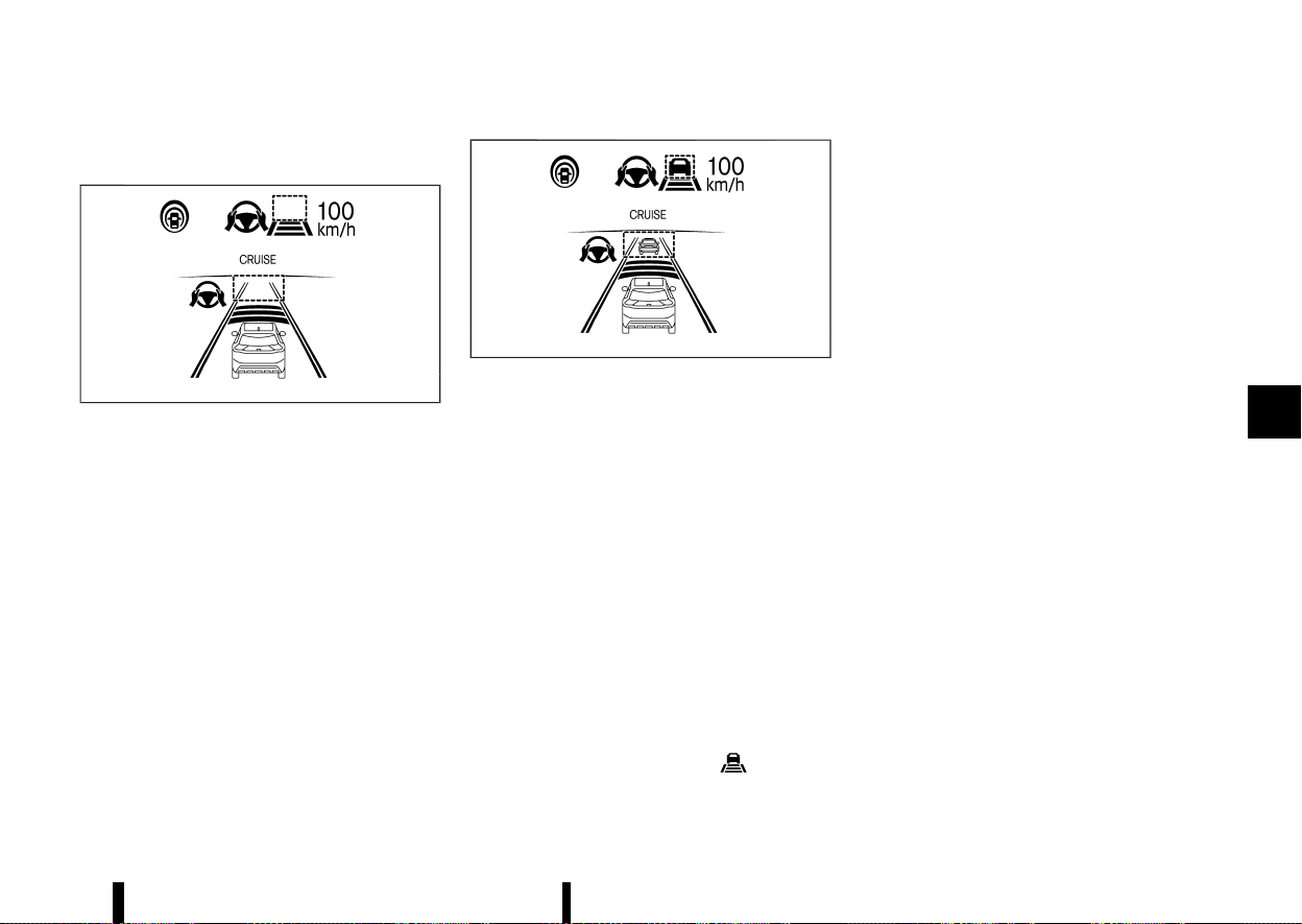
(345,1)
or if a vehicle cuts in. Always stay alert when using
the ICC system.
MWAF0845X
System set display — no vehicle detected ahead*
No vehicle detected ahead:
The driver sets the desired vehicle speed based on
the road conditions. The ICC system maintains the
vehicle set speed, similar to standard cruise
control, as long as no vehicle is detected in the
lane ahead. The ICC system displays the vehicle set
speed.
*: The design of the set display may differ depend-
ing on the model.
MWAF0846X
System set display — vehicle ahead*
Vehicle detected ahead:
When a vehicle is detected in the lane ahead, the
ICC system decelerates the vehicle by controlling
the throttle and applying the brakes to match the
speed of a slower vehicle ahead. The ICC system
then adjusts the vehicle speed based on the speed
of the vehicle ahead to maintain the driver
selected distance.
NOTE:
* The brake lights of the vehicle come on
when braking is performed by the ICC
system.
* When the brake is applied by the system, a
noise may be heard. This is not a malfunc-
tion.
When the ICC system detects a vehicle ahead, the
vehicle ahead detection indicator is displayed and
the speed control status indicator
illuminates
in green.
*: The design of the set display may differ depend-
ing on the model.
Vehicle ahead stops:
When a vehicle ahead is detected and it gradually
decelerates to stop, your vehicle decelerates to a
standstill. When your vehicle is at a standstill, the
[(RES+) Press to Restart] message is displayed on
the vehicle information display.
NOTE:
When your vehicle stops for less than 3 seconds,
your vehicle will automatically follow the vehicle
ahead as it accelerates from a stop. If your
vehicle is stationary for more than approxi-
mately 3 minutes, the ICC system will be
switched off and the electronic parking brake
will be applied.
Vehicle ahead accelerates:
* When your vehicle is at a standstill and the
vehicle ahead begins to accelerate, push up
the <RES+> switch or lightly depress the
accelerator pedal. The ICC system starts to
follow the vehicle ahead.
* Always check surroundings before restarting
the vehicle.
Vehicle ahead not detected:
When a vehicle is no longer detected ahead, the
ICC system gradually accelerates your vehicle to
resume the previously vehicle set speed. The ICC
system then maintains the vehicle set speed.
When a vehicle is no longer detected, the vehicle
ahead detection indicator and speed control
Starting and driving 341
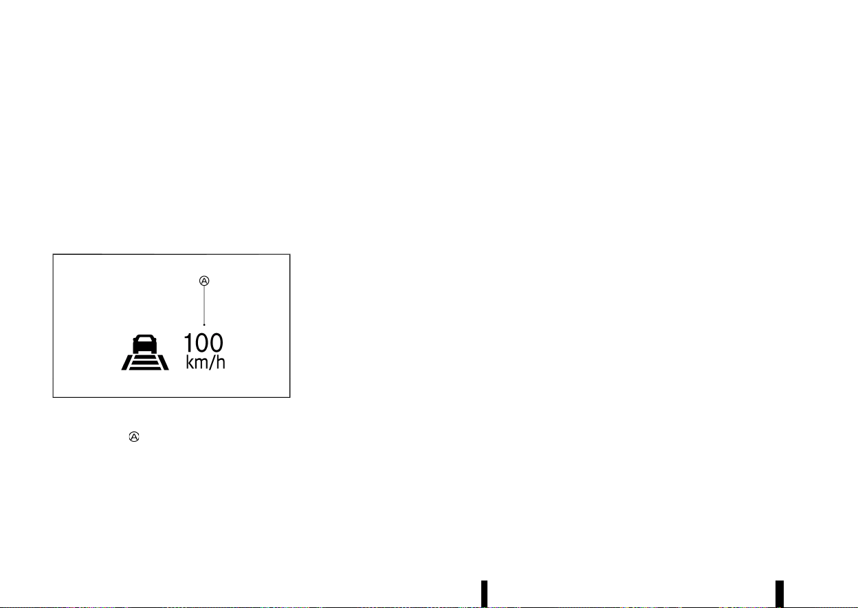
(346,1)
342 Starting and driving
status indicator (maintain speed control mode)
turn off.
The ICC system gradually accelerates to the
vehicle set speed, but you can depress the accel-
erator pedal to quickly accelerate. When a vehicle
is no longer detected and your vehicle is travelling
under approximately 25 km/h (15 MPH), the ICC
system automatically cancels.
The ICC system cancels and a chime sounds if your
vehicle is at a standstill for more than approxi-
mately 3 seconds and a vehicle is not detected
ahead.
MWAF0847X
When passing another vehicle, the vehicle set
speed indicator
flashes when the vehicle speed
exceeds the set speed. The vehicle ahead detec-
tion indicator turns off when the area ahead of the
vehicle is open. When the pedal is released, the
vehicle returns to the previously set speed. Even
though your vehicle speed is set in the ICC system,
you can depress the accelerator pedal when it is
necessary to accelerate your vehicle rapidly.
Approach warning
MEVT33A1-0C918255-CF2D-4A25-BAA9-F864DFAEDCEE
If your vehicle comes closer to the vehicle ahead
due to rapid deceleration of that vehicle or if
another vehicle cuts in, the system warns the
driver with the chime and ICC system display.
Decelerate by depressing the brake pedal to
maintain a safe vehicle distance if:
* The chime sounds.
* The vehicle ahead detection indicator blinks.
* You judge it necessary to maintain a safe
distance.
The warning chime may not sound in some cases
when there is a short distance between vehicles.
Some examples are:
* When the vehicles are travelling at the same
speed and the distance between vehicles is
not changing.
* When the vehicle ahead is travelling faster and
the distance between vehicles is increasing.
* When a vehicle cuts in near your vehicle.
The warning chime will not sound when:
* Your vehicle approaches other vehicles that
are parked or moving slowly.
* The accelerator pedal is depressed, overriding
the system.
NOTE:
The approach warning chime may sound and
the system display may flash when the radar
sensor detects objects on the side of the vehicle
or on the side of the road. This may cause the
ICC system to decelerate or accelerate the
vehicle. The radar sensor may detect these
objects when the vehicle is driven on winding,
narrow, or hilly roads or when the vehicle is
entering or exiting a curve. In these cases, you
will have to manually control the proper dis-
tance ahead of your vehicle.
Also, the sensor sensitivity can be affected by
vehicle operation (steering manoeuvre or driv-
ing position in the lane) or traffic or vehicle
conditions (for example, if a vehicle is being
driven with some damage).
Acceleration when passing (where fitted)
MEVT33A1-0508E008-E730-4916-AC39-9A366BE948DB
Passing on the left-hand side (for countries
where traffic travels on the right-hand side of
the road):
When the ICC system is engaged above 70 km/h
(44 MPH) and following a slower vehicle (below the
ICC set speed), and the turn signal is activated to
the left, the ICC system will automatically start to
accelerate the vehicle to help initiate passing on
the left and will begin to reduce the distance to
vehicle directly ahead. Only the left side turn signal
operates this feature. As the driver steers the
vehicle and moves into the passing lane, if no
vehicle is detected ahead the ICC system will
continue to accelerate to the vehicle set speed. If
another vehicle is detected ahead, then the vehicle
will accelerate up to the following speed of that
vehicle. If the vehicle is not steered into the left
lane to pass, the acceleration will stop after a short
time and regain the set following distance. Accel-
eration can be stopped at any point by depressing
the brake pedal or the <CANCEL> switch on the
steering wheel.

(347,1)
Passing on the right-hand side (for countries
where traffic travels on the left-hand side of the
road):
When the ICC system is engaged above 70 km/h
(44 MPH) and following a slower vehicle (below the
ICC set speed), and the turn signal is activated to
the right, the ICC system will automatically start to
accelerate the vehicle to help initiate passing on
the right and will begin to reduce the distance to
vehicle directly ahead. Only the right side turn
signal operates this feature. As the driver steers
the vehicle and moves into the passing lane, if no
vehicle is detected ahead the ICC system will
continue to accelerate to the vehicle set speed. If
another vehicle is detected ahead, then the vehicle
will accelerate up to the following speed of that
vehicle. If the vehicle is not steered into the right
lane to pass, the acceleration will stop after a short
time and regain the set following distance. Accel-
eration can be stopped at any point by depressing
the brake pedal or the <CANCEL> switch on the
steering wheel.
WARNING
In order to reduce the risk of a collision that
may result in serious injury or death, please be
aware of the following:
* This function is only activated with the left
or right turn signal and will briefly accel-
erate the vehicle even if a lane change is
not initiated. This can include non-passing
situations such as left or right side exits.
* Ensure that when passing another vehicle,
the adjacent lane is clear before initiating
the pass. Sudden changes in traffic may
occur while passing. Always manually
steer or brake as needed. Never solely rely
on the system.
Speed Limit Link (where fitted)
MEVT33A1-BD0AC12D-AA5C-4DE0-863F-EDC8D36CED9E
WARNING
Listed below are the system limitations for the
Speed Limit Link. Failure to operate the vehicle
in accordance with these system limitations
could result in serious injury or death:
* It is the driver’s responsibility to select the
proper speed, follow all traffic regulations
and observe other road users.
* The Speed Limit Link may not operate
properly and the actual speed limit may
not be applied to the vehicle set speed in
all conditions. The driver must manually
control the vehicle speed.
Below are some examples:
— When the Traffic Sign Recognition
(TSR) system is not functioning prop-
erly or turned off. (See “Traffic Sign
Recognition (TSR)” (P.271).)
— When driving in an area with nearby
parallel roads (for example, freeway
with a parallel service drive).
— When driving in an area where each
lane has a different speed limit sign.
— When driving on a road under con-
struction or in a construction zone.
— When end of the speed limit sign is
indicated.
* When the speed unit selected in the vehicle
information display is different to the unit
of the speed limit sign.
When the ICC system is active and it detects a
change of the speed limit, the new speed limit is
indicated and it can be applied to the vehicle set
speed manually.
The Speed Limit Link operates:
* When the detected speed limit is 30 km/h (20
MPH) and above.
* The [Speed Limit Link] is enabled in the
settings menu of the vehicle information dis-
play.
NOTE:
* In the following situations, the Speed Limit
Link will not operate:
— When an increase in the posted speed
limit is detected, but the vehicle set speed
is already faster than the new speed limit.
— When a decrease in the posted speed limit
is detected, but the vehicle set speed is
already lower than the new speed limit.
Starting and driving 343

(348,1)
344 Starting and driving
System display and indicators:
MWAF1192X
Example
1. Detected speed limit indicator
Displays the currently detected speed limit. For
additional information, see “Traffic Sign Re-
cognition (TSR)” (P.271).
Applied speed limit indicator (green frame)
Indicates the detected speed limit can be
applied to the vehicle set speed.
2. Speed Limit Link indicator
Indicates the system operation.
“
” : Manual mode is activated and a new
speed limit (faster speed value) is indicated.
“
” : Manual mode is activated and a new
speed limit (lower speed value) is indicated.
Operating the system:
When the system detects a different speed limit,
the new speed value is indicated. The vehicle set
speed can be changed to the indicated speed limit
manually.
* To accept the newly indicated speed limit,
operate the <RES+> switch (in case of speed
limit up) or <SET-> switch (in case of speed
limit down).
* The Speed Limit Link indicator (
or )
will turn off after approximately 15 seconds if
the <RES+> or <SET-> switch is not operated.
(The Speed Limit Link indicator can be turned
off immediately by operating the opposite
switch from the direction indicated by the
Speed Limit Link indicator.)
The system will not activate if a speed limit change
is not detected.
How to activate or deactivate the system:
1. Push the
button on the steering
wheel until [Settings] appears in the vehicle
information display, and push the scroll dial.
2. Use the scroll dial to select [Driver Assistance].
Then push the scroll dial.
3. Select [Speed Limit Link] and push the scroll
dial to turn the system on or off.
NOTE:
The system will retain current settings in the
vehicle information display even if the engine is
restarted.
Selecting Speed Link Offset:
It is possible to set whether the speed limit should
be accepted exactly, or with a tolerance of –10
km/h (-5 MPH) to +10 km/h (+5 MPH).
1. Push the
button on the steering
wheel until [Settings] appears in the vehicle
information display, and push the scroll dial.
2. Use the scroll dial to select [Driver Assistance].
Then push the scroll dial.
3. Select [Speed Link Offset] and push the scroll
dial to select tolerance value. (Select [OFF] to
turn off the function.)
NOTE:
The function will retain current settings in the
vehicle information display even if the engine is
restarted.
Speed Limit Link - a feature of ProPILOT
Assist with Navi-link (where fitted)
MEVT33A1-577E6A91-C43C-498D-A98B-E19B7D169040
WARNING
Listed below are the system limitations for the
Speed Limit Link. Failure to operate the vehicle
in accordance with these system limitations
could result in serious injury or death:
* It is the driver’s responsibility to select the
proper speed, follow all traffic regulations
and observe other road users.
* The Speed Limit Link may not operate
properly and the actual speed limit may
not be applied to the vehicle set speed in
all conditions. The driver must manually
control the vehicle speed.
Below are some examples:
— When the Traffic Sign Recognition
(TSR) system is not functioning prop-
erly or turned off. (See “Traffic Sign
Recognition (TSR)” (P.271).)
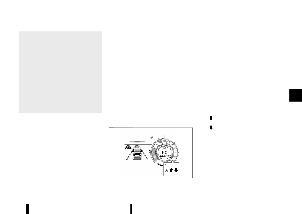
(349,1)
— When driving in countries or areas not
covered by the navigation system.
— When crossing national boundaries.
— When driving on the exit of the limited
access freeway as identified in the
navigation map data.
— When driving in an area with nearby
parallel roads (for example, freeway
with a parallel service drive).
— When driving in an area where each
lane has a different speed limit sign.
— When driving on a road under con-
struction or in a construction zone.
— When the data from the navigation
system is not up-to-date or is unavail-
able.
When the ProPILOT Assist with Navi-link is active
and it detects a change of the speed limit, the new
speed limit is indicated and it can be applied to the
vehicle set speed automatically or manually.
The Speed Limit Link operates:
* When the detected speed limit is 30 km/h (20
MPH) and above.
* The [Speed Limit Link] is enabled in the
settings menu of the vehicle information dis-
play.
NOTE:
* While the accelerator pedal is operated with
AUTO mode selected, the Speed Limit Link
will function (automatically adjust the vehi-
cle set speed) only when the detected speed
limit is faster than the vehicle set speed.
* In the following situations, the Speed Limit
Link will not operate:
— When an increase in the posted speed
limit is detected, but the vehicle set speed
is already faster than the new speed limit.
— When a decrease in the posted speed limit
is detected, but the vehicle set speed is
already lower than the new speed limit.
For Germany (No Limit speed setting):
When you turn on the engine and subsequently
enter a freeway with no speed limit, the system
initially regulates the speed to 130 km/h (81 MPH).
After this, the last speed stored by the driver on a
freeway with no speed limit is applied.
NOTE:
This feature only works in Germany.
System display and indicators:
MWAF1249X
Example
1. Detected speed limit indicator
Left side:
Displays detected impending or anticipated
speed limit. This speed limit will only be
indicated when a new speed limit (lower speed
value) is detected in Manual mode.
Right side:
Displays the currently detected speed limit. For
additional information, see “Traffic Sign Re-
cognition (TSR)” (P.271).
Applied speed limit indicator (green frame)
Indicates the detected speed limit can be
applied to the vehicle set speed.
2. Speed Limit Link indicator
Indicates the system activation mode or
system operation.
“
” : Manual mode is activated and a new
speed limit (faster speed value) is indicated.
“
” : Manual mode is activated and a new
speed limit (lower speed value) is indicated.
“A” : Auto mode is activated.
Operating the system:
When the system detects a different speed limit,
the new speed value is indicated. The vehicle set
speed can be changed to the indicated speed limit
automatically or manually.
When Manual mode is selected on settings
menu (factory default setting):
* To accept the newly indicated speed limit,
operate the <RES+> switch (in case of speed
Starting and driving 345

(350,1)
346 Starting and driving
limit up) or <SET-> switch (in case of speed
limit down).
* The Speed Limit Link indicator (
or )
will turn off after approximately 15 seconds if
the <RES+> or <SET-> switch is not operated.
(The Speed Limit Link indicator can be turned
off immediately by operating the opposite
switch from the direction indicated by the
Speed Limit Link indicator.)
The system will not activate if a speed limit change
is not detected.
When Auto mode is selected on the settings
menu:
* The indicated speed limit is applied to the
vehicle set speed automatically when on a
limited access freeway as identified in the
navigation map data. Also, if the ProPILOT
Assist with Navi-link system is ON, but not set
(active), and a new speed limit is detected, the
vehicle set speed is automatically updated.
* The Auto mode may not be available in some
regions or on roads other than limited access
freeways. In this case, the system operates as
the Manual mode.
How to activate or deactivate the system:
1. Push the
button on the steering
wheel until [Settings] appears in the vehicle
information display, and push the scroll dial.
2. Use the scroll dial to select [Driver Assistance].
Then push the scroll dial.
3. Select [Speed Limit Link], and push the scroll
dial to select [Auto] or [Prompt] to enable (not
activate) the system.
To deactivate the system, select [OFF].
NOTE:
The system will retain current settings in the
vehicle information display even if the engine is
restarted.
Selecting Speed Link Offset:
It is possible to set whether the speed limit should
be accepted exactly, or with a tolerance of –10
km/h (-5 MPH) to +10 km/h (+5 MPH).
1. Push the
button on the steering
wheel until [Settings] appears in the vehicle
information display, and push the scroll dial.
2. Use the scroll dial to select [Driver Assistance].
Then push the scroll dial.
3. Select [Speed Link Offset] and push the scroll
dial to select tolerance value. (Select [OFF] to
turn off the function.)
NOTE:
The function will retain current settings in the
vehicle information display even if the engine is
restarted.
CRUISE Navi Link - a feature of ProPI-
LOT Assist with Navi-link (where fitted)
MEVT33A1-FBC7130F-72CF-4FD7-957E-AAA5C43C74B2
WARNING
Listed below are the system limitations for the
CRUISE Navi Link. Failure to operate the vehicle
in accordance with these system limitations
could result in serious injury or death:
* There are limitations to the CRUISE Navi
Link system capability. The system does
not function in all driving, traffic, weather
and road conditions. It is the driver’s
responsibility to stay alert, drive safely,
and be in control of the vehicle at all times.
* The CRUISE Navi Link system does not
brake the vehicle to a stop. Whenever
necessary, the driver must apply appro-
priate braking.
* It is the driver’s responsibility to select the
proper speed, follow all traffic regulations
and observe other road users.
* The availability of the CRUISE Navi Link
system is country-dependent. In some
countries, for example, Iceland, Malta, Cy-
prus, this function is not available. The
map data quality does not satisfy the
system requirements. If the system de-
tects that the vehicle is located in these
countries on the basis of GPS information,
the system prohibits activation of the
CRUISE Navi Link function.
* The CRUISE Navi Link may not operate
properly in some road and traffic condi-
tions, the system may unexpectedly
change the speed. The driver must manu-
ally control the vehicle speed.
Below are some examples:
— When driving in countries or areas not
covered by the navigation system.
— When the data from the navigation
system is not up-to-date or is unavail-
able.
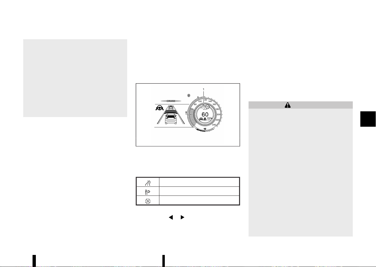
(351,1)
— When not driving along the route
suggested by the navigation system.
— When the navigation system is recal-
culating the route.
— When driving in countries or areas not
covered by the navigation system.
— When driving on a road under con-
struction or newly constructed road.
— When driving near a road split or
junction.
— When driving in bad weather or poor
road conditions.
When the ProPILOT Assist with Navi-link is active
on a limited access freeway (as identified in the
navigation map data), the CRUISE Navi Link uses
road information provided by the navigation
system and can adjust the vehicle speed depend-
ing on curves, junctions and exits.
The CRUISE Navi Link uses road information
provided by the navigation system and can adjust
the vehicle speed depending on roundabouts (as
identified in the navigation map data).
The system may not always reduce speed for all
curves, junctions, roundabouts or exits and the
driver may need to apply additional braking at any
time.
When the vehicle is through the curve, roundabout
or junction, the vehicle will accelerate again to the
set speed. When exiting the limited access freeway,
the driver will need to apply braking at the end of
the exit.
NOTE:
* The system does not operate when the
accelerator pedal is depressed.
* The system may not operate depending on
the set distance to the vehicle ahead and
vehicles detected ahead.
System display and indicators:
MWAF1250X
Example
1. Road information indicator
Appears when the system adjusts the speed
depending on turns or exits.
Curves and junctions
Exits
Roundabouts
How to activate or deactivate the system:
1. Push the
button on the steering
wheel until [Settings] appears in the vehicle
information display, and push the scroll dial.
2. Use the scroll dial to select [Driver Assistance].
Then push the scroll dial.
3. Select [CRUISE Navi Link] and push the scroll
dial to turn the system on or off.
NOTE:
The system will retain current settings in the
vehicle information display even if the engine is
restarted.
ICC system limitations
MEVT33A1-F6F6C837-85BC-494B-8B8B-A721BAC341D1
WARNING
Listed below are the system limitations for the
ICC system. Failure to operate the vehicle in
accordance with these system limitations
could result in serious injury or death:
* The ICC system is primarily intended for
use on straight, dry, open roads with light
traffic. It is not advisable to use the ICC
system in city traffic or congested areas.
* The ICC system will not adapt automati-
cally to road conditions. This system
should be used in evenly flowing traffic.
Do not use the system on roads with sharp
curves or on icy roads, in heavy rain or in
fog.
* As there is a performance limit to the
distance control function, never rely solely
on the ICC system. This system does not
correct careless, inattentive or absent-
minded driving or overcome poor visibility
in rain, fog, or other bad weather. Decele-
rate the vehicle speed by depressing the
brake pedal, depending on the distance to
Starting and driving 347

(352,1)
348 Starting and driving
the vehicle ahead and the surrounding
circumstances in order to maintain a safe
distance between vehicles.
* When the ICC system automatically brings
the vehicle to a stop, your vehicle can
automatically accelerate if the vehicle is
stopped for less than approximately 3
seconds. Be prepared to stop your vehicle
if necessary.
* Always check surroundings before restart-
ing the vehicle.
* Always pay attention to the operation of
the vehicle and be ready to manually
control the proper following distance. The
ICC system may not be able to maintain
the selected distance between vehicles
(following distance) or selected vehicle
speed under some circumstances.
* The ICC system does not detect the follow-
ing objects:
— Stationary or slow moving vehicles
(when your vehicle is approaching
them)
— Pedestrians or objects in the roadway
— Oncoming vehicles in the same lane
— Motorcycles travelling offset in the
travel lane
* The ICC system may not detect a vehicle
ahead in certain road, weather or driving
conditions. To avoid accidents, never use
the ICC system under the following condi-
tions:
— On roads with heavy, high-speed traf-
fic or sharp curves
— On slippery road surfaces such as on
ice or snow, etc.
— On a bumpy road surface, such as an
uneven dirt road
— On steep downhill roads (the vehicle
may go beyond the vehicle set speed
and frequent braking may result in
overheating the brakes)
— On repeated uphill and downhill roads
— During bad weather (rain, fog, snow,
etc.)
— When the sensor detection is reduced
(conditions such as rain, snow, fog,
dust storms, sandstorms, and road
spray from other vehicles)
— When dirt, ice, snow or other material
adhere to the radar sensor area
— When traffic conditions make it diffi-
cult to keep a proper distance be-
tween vehicles because of frequent
acceleration or deceleration
— When a complicated-shaped vehicle
such as a car carrier trailer or flatbed
truck/trailer is near the vehicle ahead
— When there is interference by other
radar sources
— When excessively heavy baggage is
loaded in the rear seat or cargo area
of your vehicle
* Do not use the ICC system if you are towing
a trailer or other vehicle. The system may
not detect a vehicle ahead.
* In some road or traffic conditions, a vehicle
or object can unexpectedly come into the
sensor detection zone and cause auto-
matic braking. Always stay alert and avoid
using the ICC system where not recom-
mended in this warning section.
* The ICC system also uses a multi-sensing
front camera. The following are some
conditions in which the camera may not
properly detect a vehicle and detection of
a vehicle ahead may be delayed:
— Poor visibility (conditions such as rain,
snow, fog, dust storms, sandstorms,
and road spray from other vehicles)
— The camera area of the windscreen is
fogged up or covered with dirt, water
drops, ice, snow, etc.
— Strong light (for example, sunlight or
high beams from oncoming vehicles)
enters the front camera
— A sudden change in brightness occurs
(for example, when the vehicle enters
or exits a tunnel or shaded area or
lightning flashes)
The ICC system is designed to automatically check
the radar sensor’s operation within the limitations
of the system
The detection zone of the radar sensor is limited. A
vehicle ahead must be in the detection zone for
the ICC system to maintain the selected distance
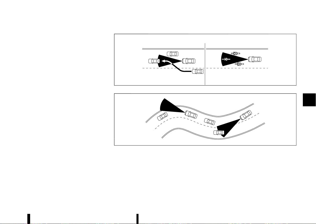
(353,1)
from the vehicle ahead. A vehicle ahead may move
outside of the detection zone due to its position
within the same lane of travel. Motorcycles may
not be detected in the same lane ahead if they are
travelling offset from the centre line of the lane. A
vehicle that is entering the lane ahead may not be
detected until the vehicle has completely moved
into the lane.
If this occurs, the ICC system may warn you by
blinking the system indicator and sounding the
chime. The driver may have to manually control
the proper distance away from the vehicle travel-
ling ahead.
MSSD0252
MSSD0253
When driving on some roads, such as winding, hilly,
curved, narrow roads, or roads which are under
construction, the radar sensor may detect vehicles
in a different lane, or may temporarily not detect a
vehicle travelling ahead. This may cause the ICC
system to decelerate or accelerate the vehicle.
The detection of vehicles may also be affected by
vehicle operation (steering manoeuvre or travel-
ling position in the lane, etc.) or vehicle condition.
If this occurs, the ICC system may warn you by
blinking the system indicator and sounding the
chime unexpectedly. You will have to manually
control the proper distance away from the vehicle
travelling ahead.
Starting and driving 349

(354,1)
350 Starting and driving
ICC system temporarily unavailable
MEVT33A1-CD429AA3-3205-42E9-B530-3144974721CA
The following are conditions in which the ICC
system may be temporarily unavailable. In these
instances, the ICC system may not cancel and may
not be able to maintain the selected following
distance from the vehicle ahead.
Condition A:
Under the following conditions, the ICC system is
automatically cancelled. A chime will sound and
the system will not be able to be set:
* Any door is open.
* The driver’s seat belt is unfastened.
* The vehicle ahead is not detected and your
vehicle is travelling below the speed of 25
km/h (15 MPH). The ICC system cancels and a
warning chime sounds if your vehicle is at a
standstill for more than approximately 3
seconds and a vehicle is not detected ahead.
* Your vehicle has been stopped by the ICC
system for approximately 3 minutes or longer.
* The shift lever is moved out of the D (Drive)
position or into the manual shift mode.
* The electronic parking brake is applied.
* The VDC/ESP system is turned off.
* The Intelligent Emergency Braking applies
harder braking
* VDC/ESP (including the traction control sys-
tem) operates.
* A wheel slips.
* When the front radar is impaired due to dirt or
an other obstruction blocking the radar sen-
sor.
* When the radar signal is temporarily inter-
rupted.
Action to take:
When the conditions listed above are no longer
present, turn the system off using the ProPILOT
Assist switch. Turn the ProPILOT Assist system
back on to use the system.
NOTE:
When the ICC system is cancelled under any of
the following conditions at a standstill, the
electronic parking brake is automatically acti-
vated:
* Any door is open.
* The driver’s seat belt is unfastened.
* Your vehicle has been stopped by the ICC
system for approximately 3 minutes or
longer.
* The shift lever is moved out of the D (Drive)
position or into the manual shift mode.
* The VDC/ESP system is turned off.
* When the front radar is impaired due to dirt
or an other obstruction blocking the radar
sensor.
* When the radar signal is temporarily inter-
rupted.
Condition B:
When there is inclement weather (rain, fog, snow,
etc.) blocking the front radar sensor, the ICC
system will automatically be cancelled, the chime
will sound and the [Temporarily Disabled Front
Radar Blocked] warning message will appear in the
vehicle information display.
Action to take:
When the above condition is no longer present, the
warning message will no longer be available in the
vehicle information display and the system will
operate normally. If the warning message con-
tinues to appear, have the system checked. It is
recommended that you visit a NISSAN dealer or
qualified workshop for this service.
Condition C:
When the radar sensor on the front of the vehicle is
covered with dirt or is obstructed, the ICC system
will automatically be cancelled.
The chime will sound and the [Temporarily Dis-
abled Front Radar Blocked] warning message will
appear in the vehicle information display.
Action to take:
If the warning message appears, stop the vehicle
in a safe place, push the park button to engage the
P (Park) position, and turn the engine off. When the
radar signal is temporarily interrupted, clean the
sensor area and restart the engine. If the warning
message continues to appear, have the system
checked. It is recommended that you visit a
NISSAN dealer or qualified workshop for this
service.
Condition D:
When driving on roads with limited road structures
or buildings (for example, long bridges, deserts,
snow fields, driving next to long walls), the system
may display the [Temporarily Disabled Front Radar
Blocked] message.
Action to take:

(355,1)
When the above driving conditions no longer exist,
turn the system back on.
ICC system malfunction
MEVT33A1-CDB0C15F-B608-4BFC-9CB9-107B835DC9B8
If the ICC system malfunctions, it will be turned off
automatically, a chime will sound, the [System fault
See Owner’s Manual] warning message will appear
and the speed control status warning (yellow) will
illuminate.
Action to take:
If the warning illuminates, stop the vehicle in a safe
place. Turn the engine off, restart the engine and
set the ICC system again. If it is not possible to set
the ICC system or the warning stays on, it may be a
malfunction. Although the normal driving can be
continued, the ICC system should be inspected. It
is recommended that you visit a NISSAN dealer or
qualified workshop for this service.
NOTE:
If the ICC system is temporarily unavailable, the
conventional cruise control mode may still be
used. For additional information, see “Conven-
tional (fixed speed) cruise control mode” (P.356).
ICC sensor maintenance
MEVT33A1-09879176-877E-4878-A9CB-5470EC006207
The radar sensor is located on the front of the
vehicle.
To keep the ICC system operating properly, be sure
to observe the following:
* Always keep the sensor area clean.
* Do not strike or damage the areas around the
sensor.
* Do not attach a sticker (including transparent
material) or install an accessory near the
sensor. This could cause failure or malfunction.
* Do not attach metallic objects near the sensor
area (brush guard, etc.). This could cause
failure or malfunction.
* Do not alter, remove, or paint the front
bumper.
Before customising or restoring the front bumper,
it is recommended that you visit a NISSAN dealer
or qualified workshop.
For the radio approval numbers and information,
see “Radio approval number and information”
(P.465).
The camera sensor is located above the inside
rearview mirror.
To keep the proper operation of the systems and
prevent a system malfunction, be sure to observe
the following:
* Always keep the windscreen clean.
* Do not attach a sticker (including transparent
material) or install an accessory near the
camera unit.
* Do not place reflective materials, such as white
paper or a mirror, on the instrument panel.
The reflection of sunlight may adversely affect
the camera unit’s capability of detecting the
lane markers.
* Do not strike or damage the areas around the
camera unit. Do not touch the camera lens or
remove the screw located on the camera unit.
If the camera unit is damaged due to an accident,
it is recommended that you visit a NISSAN dealer
or qualified workshop.
For additional information, see “Common trouble-
shooting guide” (P.267).
STEERING ASSIST
MEVT33A1-1C86E792-3941-4F8D-9B83-22BA4986E349
WARNING
Failure to follow the warnings and instructions
for proper use of the Steering Assist could
result in serious injury or death.
* The Steering Assist is not a replacement
for proper driving procedures and is not
designed to correct careless, inattentive or
absent-minded driving. The Steering Assist
will not always steer the vehicle to keep it
in the lane. It is not designed to prevent
loss of control. It is the driver’s responsi-
bility to stay alert, drive safely, keep the
vehicle in the travelling lane, and be in
control of the vehicle at all times.
* As there is a performance limit to the
Steering Assist’s capability, never rely so-
lely on the system. The Steering Assist
does not function in all driving, traffic,
weather, and road conditions. Always drive
safely, pay attention to the operation of
the vehicle, and manually control your
vehicle appropriately.
* The Steering Assist is intended for use on
well-developed motorways or highways
with gentle (moderate) curves, where traf-
fic travelling in opposing directions is
separated with a barrier. To avoid risk of
Starting and driving 351
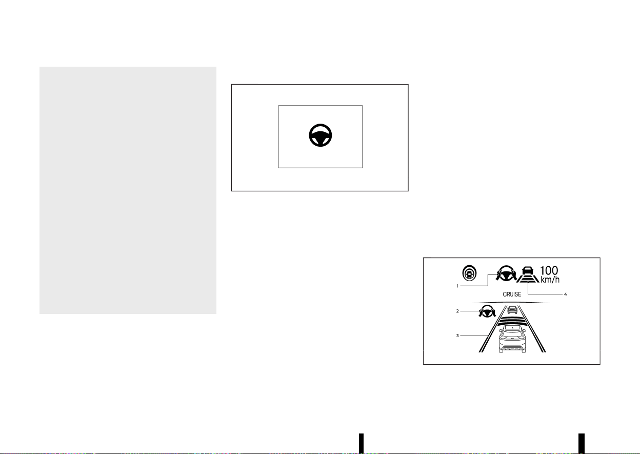
(356,1)
352 Starting and driving
an accident, do not use this system on
local or non-highway or non-urban ex-
pressway roads.
* The Steering Assist only steers the vehicle
to maintain its position in the centre of a
lane. The vehicle will not steer to avoid
objects in the road in front of the vehicle or
to avoid a vehicle moving into your lane.
* It is the driver’s responsibility to stay alert,
drive safely, keep the vehicle in the travel-
ling lane, and be in control of the vehicle at
all times. Never take your hands off the
steering wheel when driving. Always keep
your hands on the steering wheel and
drive your vehicle safely.
* Always drive carefully and attentively
when using the Steering Assist. Read and
understand the Owner’s Manual thor-
oughly before using the Steering Assist.
To avoid serious injury or death, do not rely
on the system to prevent accidents or to
control the vehicle’s speed in emergency
situations. Do not use the Steering Assist
except in appropriate road and traffic
conditions.
Steering Assist switch
MEVT33A1-4AD0F4B3-5DCF-4677-8D02-BBB42E6F27AE
MWAF0222X
The Steering Assist switch is used to temporarily
turn on and off the Steering Assist system.
You can also use the [Driver Assistance] menu in
the vehicle information display to turn on and off
the Steering Assist system. (See “How to enable/
disable the Steering Assist” (P.338).)
The Steering Assist system controls the steering
system to help keep your vehicle near the centre of
the lane when driving. (See “ProPILOT Assist (where
fitted)” (P.329).)
Steering Assist operation
MEVT33A1-A80E7170-B008-492C-A245-6CE5597AD035
Steering Assist helps the driver keep the vehicle
near the centre of the lane when both right and
left lane markers are detected. Steering Assist only
operates when combined with the Intelligent
Cruise Control (ICC) system. For additional infor-
mation, see “Intelligent Cruise Control (ICC)” (P.339).
The Steering Assist can be activated when the
following conditions are met:
* The ICC system is activated.
* Lane markers on both sides are clearly de-
tected.
* Your vehicle is travelling at speed over 60
km/h (37 MPH), or a vehicle is detected in front
of you when travelling under 60 km/h (37
MPH).
* The driver grips the steering wheel.
* The vehicle is driven at the centre of the lane.
* The turn signals are not operated.
* The windscreen wiper is not operated in the
high speed position (the Steering Assist func-
tion is disabled after the wiper operates for
approximately 10 seconds in the high speed
position).
To enable or disable the Steering Assist, see “How
to enable/disable the Steering Assist” (P.338).
Steering Assist display and indicators
MEVT33A1-C9DAD00E-F677-40A5-9DE1-89E7536C94CE
MWAF0848X
Example
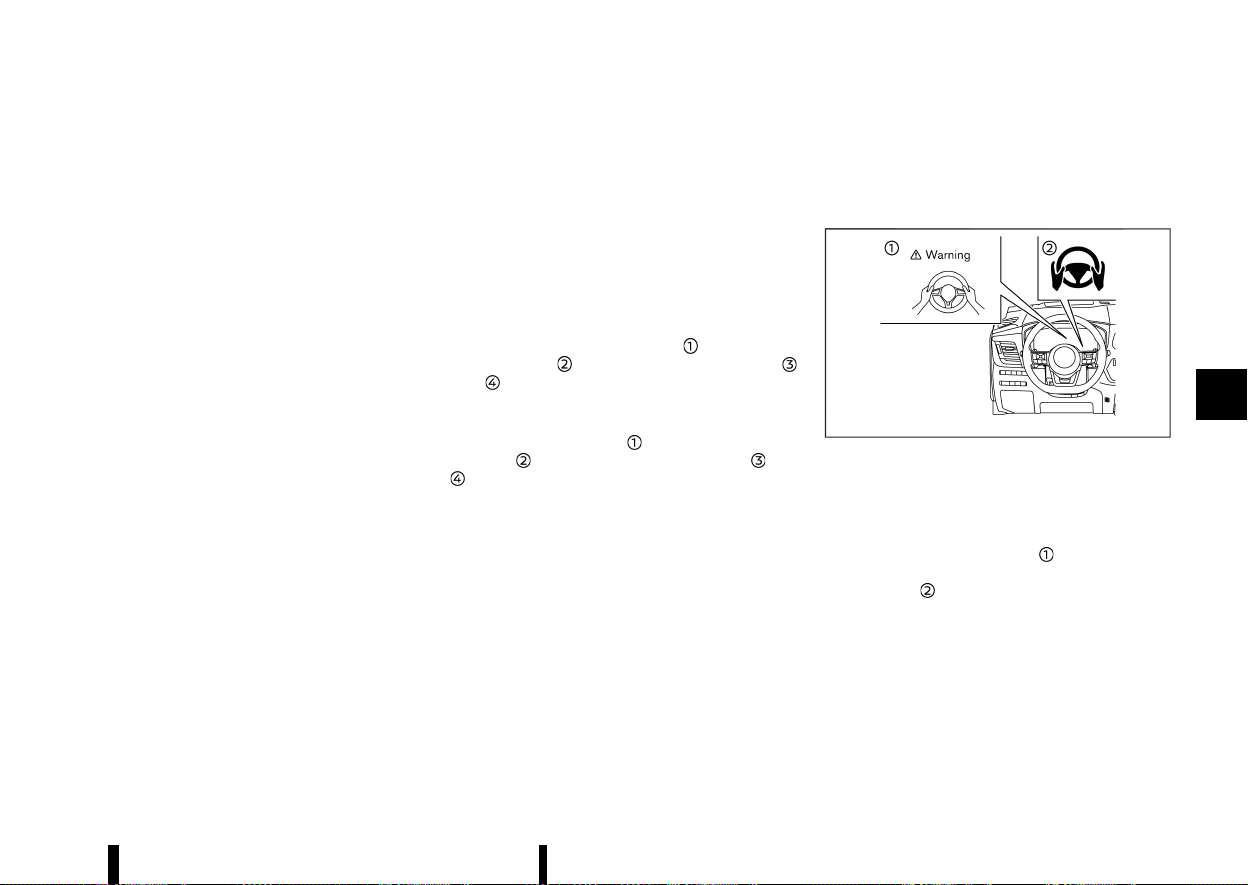
(357,1)
1. Steering Assist status indicator/warning
Displays the status of the Steering Assist by
the colour of the indicator/warning
.
Steering Assist status indicator (grey):
Steering Assist standby
.
Steering Assist status indicator (green):
Steering Assist active
.
Steering Assist status indicator (yellow):
Steering Assist malfunction
.
Steering Assist status indicator (red): Hands
off detected
2. Steering Assist indicator
Indicates the status of the Steering Assist by
the colour of the indicator
.
Steering Assist indicator (grey): Steering
Assist standby
.
Steering Assist indicator (green): Steering
Assist active
3. Lane marker indicator
Indicates whether the system detects the lane
marker
.
Lane marker indicator (grey): Lane markers
not detected
.
Lane marker indicator (green): Lane mar-
kers detected
.
Lane marker indicator (yellow): Lane depar-
ture is detected
4. Lane marker indicator/speed control status
indicator/set distance indicator
Displays the status of the Steering Assist by
the colour of the lane marker indicator.
Lane marker indicator (no lane): Steering
Assist is turned off
.
Lane marker indicator (grey): Steering Assist
standby
.
Lane marker indicator (green): Steering
Assist active
For the speed control status indicator and set
distance indicator, see “ProPILOT Assist system
display and indicators” (P.333).
When the Steering Assist is in operation, the
Steering Assist status indicator
, the Steering
Assist indicator
, and the lane marker indicator
and on the vehicle information display turn
green.
When the Steering Assist deactivates, the Steering
Assist status indicator
, the Steering Assist
indicator
, and the lane marker indicator and
on the vehicle information display turn grey and
a chime sounds twice.
Intelligent Lane Intervention
MEVT33A1-621FF46A-62C5-452B-B650-1BF95D8AA1C7
With the Steering Assist active, when a curve or
strong cross wind exceeds the capabilities of the
system and your vehicle approaches either the left
or the right side of the travelling lane, the
Intelligent Lane Intervention system will flash the
Intelligent Lane Intervention indicator on the
vehicle information display and provide steering
wheel vibration to alert the driver. The warning
chime will also sound. Then, the Intelligent Lane
Intervention system automatically applies the
brakes for a short period of time to help assist
the driver to return the vehicle to the centre of the
travelling lane. This action is in addition to any
Steering Assist actions and the warnings cannot
be turned off. For more information, see “Intelligent
Lane Intervention (where fitted)” (P.277).
Hands on detection
MEVT33A1-5C0FE079-91E2-49B9-8569-76DBB79DD03A
MWAF0639X
When the Steering Assist is activated, it monitors
the driver’s steering wheel operation.
If the steering wheel is not operated or the driver
takes his/her hands off the steering wheel for a
period of time, the warning
appears in the
vehicle information display and the hands OFF
warning light
illuminates.
If the driver does not operate the steering wheel
after the warning has been displayed and the
warning light illuminated, an audible alert sounds
and both the warning and the warning light flash.
If the driver still does not operate the steering
wheel, the system applies a momentary brake
application to request the driver to take control of
the vehicle again.
If the driver still does not respond, the system
Starting and driving 353

(358,1)
354 Starting and driving
turns on the hazard flasher and slows the vehicle
to a complete stop.
The driver can cancel the deceleration at any time
by steering, braking, accelerating, or operating the
ProPILOT Assist switch.
WARNING
Steering Assist is not a system for a hands-free
driving. Always keep your hands on the steer-
ing wheel and drive your vehicle safely. Failure
to do so could cause a collision resulting in
serious personal injury or death.
NOTE:
The sensors may not detect the driver’s hand(s)
on the steering wheel in the following situations
and a sequence of warnings may occur:
* Driving with gloves.
* Protective covers on the steering wheel.
* Gripping the part of the steering wheel
without sensors, including leather joints
and spokes.
Steering Assist limitations
MEVT33A1-6974F9AD-D966-4459-9D25-C3FF3DDBB5E7
WARNING
* In the following situations, the camera
may not detect lane markers correctly or
may detect lane markers incorrectly and
the Steering Assist may not operate prop-
erly:
— When driving on roads where there are
multiple parallel lane markers, lane
markers that are faded or not painted
clearly, non-standard lane markers, or
lane markers covered with water, dirt,
snow, etc.
— When driving on roads with discontin-
ued lane markers
— When driving on roads with a widening
or narrowing lane width
— When driving on roads where there are
multiple lanes or unclear lane markers
due to road construction
— When driving on roads where there are
sharply contrasting objects, such as
shadows, snow, water, wheel ruts,
seams, or lines remaining after road
repairs (the Steering Assist could de-
tect these items as lane markers)
— When driving on roads where the
travelling lane merges or separates
* Do not use the Steering Assist under the
following conditions because the system
may not properly detect lane markers.
Doing so could cause a loss of vehicle
control and result in an accident.
— During bad weather (rain, fog, snow,
dust, etc.)
— When rain, snow, sand, etc., is thrown
up by the wheels of other vehicles
— When dirt, oil, ice, snow, water, or
another object adheres to the camera
unit
— When the lens of the camera unit is
foggy
— When strong light (for example, sun-
light or high beams from oncoming
vehicles) shines on the camera
— When the headlights are not bright
due to dirt on the lens or the head-
lights are off in tunnels or darkness
— When a sudden change in brightness
occurs (for example, when the vehicle
enters or exits a tunnel or is under a
bridge)
— When driving on roads where the
travelling lane merges or separates
or where there are temporary lane
markers because of road construction
— When there is a lane closure due to
road repairs
— When driving on a bumpy road sur-
face, such as an uneven dirt road
— When driving on sharp curves or wind-
ing roads
— When driving on repeated uphill and
downhill roads
* Do not use the Steering Assist under the
following conditions because the system
will not operate properly:
— When driving with a tyre that is not
within normal tyre conditions (for ex-
ample, tyre wear, abnormal tyre pres-
sure, installation of a spare tyre, tyre
chains, non-standard wheels)
— When the vehicle is equipped with

(359,1)
non-original brake or suspension
parts
— When an object such as a sticker or
cargo obstructs the camera
— When excessively heavy baggage is
loaded in the rear seat or luggage
area of your vehicle
— When the vehicle load capacity is
exceeded
— When towing a trailer or other vehicle
* Excessive noise will interfere with the
warning chime sound, and the beep may
not be heard.
* For the ProPILOT Assist system to operate
properly, the windscreen in front of the
camera must be clean. Replace worn wiper
blades. The correct size wiper blades must
be used to help make sure the windscreen
is kept clean. Only use Genuine NISSAN
wiper blades, or equivalent wiper blades,
that are specifically designed for use on
your vehicle model and model year. It is
recommended that you visit your NISSAN
dealer or qualified workshop for the cor-
rect parts for your vehicle.
Steering Assist temporary standby
MEVT33A1-A0B5902B-4E22-4C64-820A-03C875E1DD8D
Automatic standby due to driving operation:
When the driver activates the turn signal, the
Steering Assist is temporarily placed in a standby
mode. (The Steering Assist restarts automatically
when the operating conditions are met again.)
Automatic standby:
In the following cases, a double chime sounds and
the Steering Assist is placed in a temporary
standby mode. (The Steering Assist restarts auto-
matically when the operating conditions are met
again.)
* When the current travelling lane is too narrow
to operate
* When a corner is too tight and the vehicle
cannot stay in the travelling lane
* When lane markers on both sides are no
longer detected
* When a vehicle ahead is no longer detected
under approximately 60 km/h (37 MPH)
* When strong light enters the camera unit (For
example, the light directly shines on the front
of the vehicle at sunrise or sunset)
* When the temperature of the camera is too
high
NOTE:
For vehicles equipped with ProPILOT Assist with
Navi-link on a limited access freeway as identi-
fied in the navigation map data, the Steering
Assist may continue to operate with visible lane
markers on both sides even when the vehicle
speed is below approximately 60 km/h (37 MPH)
and a vehicle is not detected ahead.
Steering Assist cancel
MEVT33A1-EC41E86E-9C3D-429E-85BD-57D343148AB3
Under the following conditions, the Steering Assist
cancels, the chime sounds twice, the warning
message appears, and the Steering Assist status
indicator and the Steering Assist indicator turn off:
* When unusual lane markers appear in the
travelling lane or when the lane marker cannot
be correctly detected for some time due to
certain conditions (for example, a snow rut, the
reflection of light on a rainy day, the presence
of several unclear lane markers)
* When the windscreen wiper operates in the
high speed operation (the Steering Assist is
disabled when the wiper operates for more
than approximately 10 seconds)
Action to take:
When the conditions listed above are no longer
present, turn Steering Assist on again using the
Steering Assist switch.
Steering Assist malfunction
MEVT33A1-769AA251-9B35-476F-A2BE-DCE8AD01E049
When the system malfunctions, it turns off auto-
matically. The Steering Assist status warning
(yellow) illuminates and the [System fault See
Owner’s Manual] warning message will appear in
the vehicle information display. A chime may
sound depending on the situation.
Action to take:
Stop the vehicle in a safe location, push the park
button to shift to the P (Park) position, turn the
engine off, restart the engine, resume driving, and
set the ICC system again. If the warning (yellow)
continues to illuminate, the Steering Assist is
malfunctioning. Although the vehicle is still driva-
ble under normal conditions, have the system
checked. It is recommended that you visit a
NISSAN dealer or qualified workshop for this
service.
Starting and driving 355
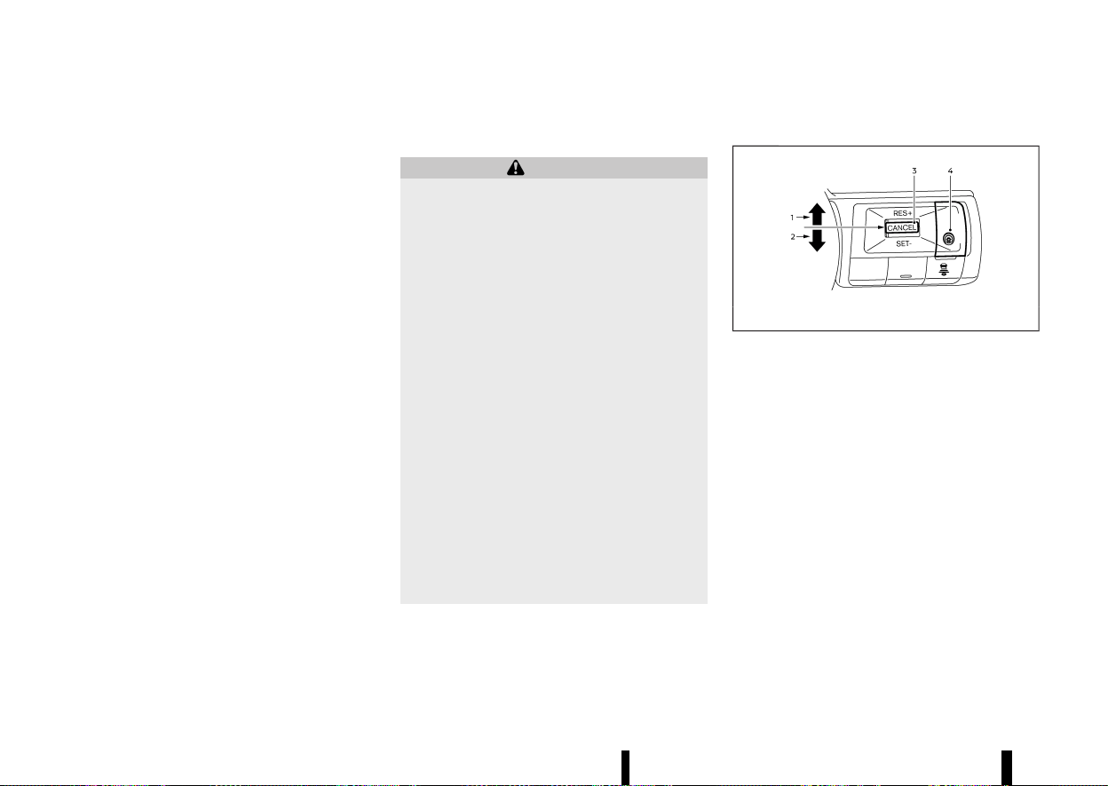
(360,1)
356 Starting and driving
Steering Assist maintenance
MEVT33A1-4B7F0042-7515-411D-8C38-DFD18C553FC7
The camera is located above the inside rearview
mirror.
To keep the proper operation of the system and
prevent a system malfunction, be sure to observe
the following:
* Always keep the windscreen clean.
* Do not attach a sticker (including transparent
material) or install an accessory near the
camera unit.
* Do not place reflective materials, such as white
paper or a mirror, on the instrument panel.
The reflection of sunlight may adversely affect
the camera unit’s capability of detecting the
lane markers.
* Do not strike or damage the areas around the
camera unit. Do not touch the camera lens or
remove the screw located on the camera unit.
If the camera unit is damaged due to an accident,
it is recommended that you visit a NISSAN dealer
or qualified workshop.
For additional information, see “Common trouble-
shooting guide” (P.267).
CONVENTIONAL (fixed speed) CRUISE
CONTROL MODE
MEVT33A1-1D9973D7-B158-4072-A66E-C61A9EE60E82
NOTE:
ProPILOT Assist provides no approach warnings,
automatic braking, or Steering Assist in the
conventional (fixed speed) cruise control mode.
This mode allows driving at a speed above
approximately 30 km/h (20 MPH) without keeping
your foot on the accelerator pedal.
WARNING
* In the conventional (fixed speed) cruise
control mode, a warning chime does not
sound to warn you if you are too close to
the vehicle ahead, as neither the presence
of the vehicle ahead nor the vehicle-to-
vehicle distance is detected.
* Pay special attention to the distance be-
tween your vehicle and the vehicle ahead
of you or a collision could occur.
* Always confirm the setting in the ICC
system display.
* Do not use the conventional (fixed speed)
cruise control mode when driving under
the following conditions:
— When it is not possible to keep the
vehicle at a set speed
— In heavy traffic or in traffic that varies
in speed
— On winding or hilly roads
— On slippery roads (rain, snow, ice, etc.)
— In very windy areas
* Doing so could cause a loss of vehicle
control and result in an accident.
Conventional (fixed speed) CRUISE CONTROL SWITCHES
MEVT33A1-8EEDA6C7-A3FC-4A32-BF0E-6E102CD1369B
MWAF0426X
1. <RES+> switch:
Resumes vehicle set speed or increases speed
incrementally
2. <SET-> switch:
Sets desired cruise speed or reduces speed
incrementally
3. <CANCEL> switch:
Deactivates the system without erasing the
vehicle set speed
4. ProPILOT Assist switch:
Turns the system on or off
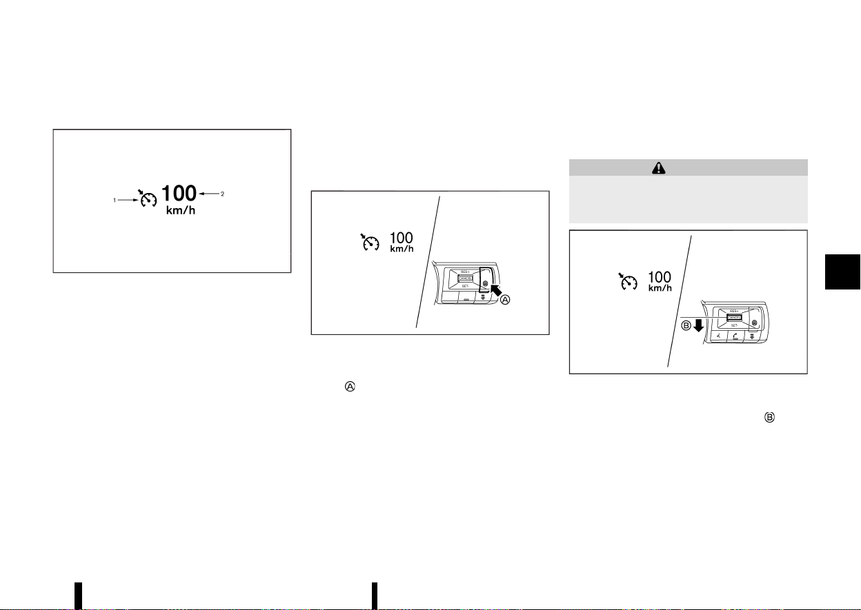
(361,1)
Conventional (fixed speed) CRUISE CON-
TROL MODE DISPLAY AND INDICATORS
MEVT33A1-F16D53E5-F62B-4EB2-99EC-9ADFD4D7CD3D
MJVS0317X
The display is located in the vehicle information
display.
1. Cruise indicator:
This indicator indicates the condition of the
ICC system depending on a colour.
.
Cruise control ON indicator (grey): Indicates
that the ProPILOT Assist switch is on
.
Cruise control SET indicator (green): Indi-
cates that the cruising speed is set
.
Cruise control warning (yellow): Indicates
that there is a malfunction in the ICC
system
2. Vehicle set speed indicator:
This indicator indicates the vehicle set speed.
.
Green: Cruise control active
.
Grey: Cruise control standby
(The speed unit can be converted between
“km/h” and “MPH”. See “[Unit/Language]”
(P.89).)
Operating conventional (fixed speed)
CRUISE CONTROL MODE
MEVT33A1-B7958E27-93F8-4BA7-8A04-45E37B56801D
MWAF0850X
To turn on the conventional (fixed speed) cruise
control mode, push and hold the ProPILOT Assist
switch
for longer than about 1.5 seconds.
When pushing the ProPILOT Assist switch on, the
conventional (fixed speed) cruise control mode
display and indicators are displayed in the vehicle
information display. After you hold the ProPILOT
Assist switch on for longer than about 1.5 seconds,
the ICC system display turns off. The cruise
indicator appears. You can now set your desired
cruising speed. Pushing the ProPILOT Assist switch
again will turn the system completely off. When the
ignition switch is placed in the “OFF” position, the
system is also automatically turned off.
To use the ICC system again, quickly push and
release the ProPILOT Assist switch (vehicle-to-
vehicle distance control mode) or push and hold
it (conventional cruise control mode) again to turn
it on.
WARNING
To avoid accidentally engaging cruise control,
make sure to turn the ProPILOT Assist switch
off when not using the ICC system.
MWAF0851X
Example
To set cruising speed, accelerate your vehicle to
the desired speed, push down the <SET->
switch
and release it. (The colour of the cruise indicator
changes to green and vehicle set speed indicator
comes on.) Take your foot off the accelerator
pedal. Your vehicle will maintain the set speed.
* To pass another vehicle, depress the accel-
erator pedal. When you release the pedal, the
vehicle will return to the previously set speed.
Starting and driving 357
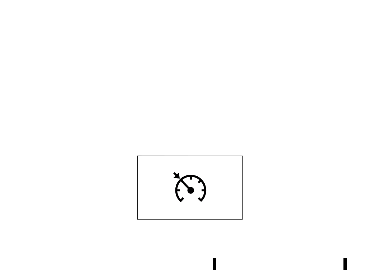
(362,1)
358 Starting and driving
* The vehicle may not maintain the set speed
when going up or down steep hills. If this
happens, manually maintain vehicle speed.
To cancel the preset vehicle speed, use any of the
following methods:
* Push the <CANCEL> switch. The vehicle set
speed indicator and the cruise indicator will
turn grey.
* Tap the brake pedal. The vehicle set speed
indicator and the cruise indicator will turn
grey.
* Turn the ProPILOT Assist switch off. Both the
cruise indicator and vehicle set speed indica-
tor will turn off.
To reset at a faster cruising speed, use one of the
following three methods:
* Depress the accelerator pedal. When the
vehicle attains the desired speed, push down
and release the <SET-> switch.
* Push up and hold the <RES+> switch. When the
vehicle attains the desired speed, release the
switch.
* Push up, then quickly release the <RES+>
switch. Each time you do this, the vehicle set
speed will increase by about 1 km/h (1 MPH).
To reset at a slower cruising speed, use one of the
following three methods:
* Lightly tap the brake pedal. When the vehicle
attains the desired speed, push down the
<SET-> switch and release it.
* Push down and hold the <SET-> switch.
Release the switch when the vehicle slows
down to the desired speed.
* Push down, then quickly release the <SET->
switch. Each time you do this, the vehicle set
speed will decrease by about 1 km/h (1 MPH).
To resume the preset vehicle speed, push up and
release the <RES+> switch. The vehicle will resume
the last set cruising speed when the vehicle speed
is over 30 km/h (20 MPH).
System temporarily unavailable
MEVT33A1-C5F10C8A-93CE-4C17-9713-155C2857853B
A chime sounds under the following conditions
and the control is automatically cancelled.
* When the shift lever is not in the D (Drive)
position
* When the parking brake is applied
* When the VDC/ESP system (including the
traction control system) operates
* When the VDC/ESP system is turned off
* When a wheel slips
Warning
MJVS1003X
When the system is not operating properly, the
chime sounds and the colour of the cruise
indicator will change to yellow.
Action to take:
If the colour of the cruise indicator changes to
yellow (cruise control warning), park the vehicle in
a safe place. Turn the engine off, restart the
engine, resume driving and then perform the
setting again.
If it is not possible to set or the indicator stays
on, it may indicate that the system is malfunc-
tioning. Although the vehicle is still driveable
under normal conditions, have the vehicle
checked. It is recommended you visit a NISSAN
dealer or qualified workshop for this service.
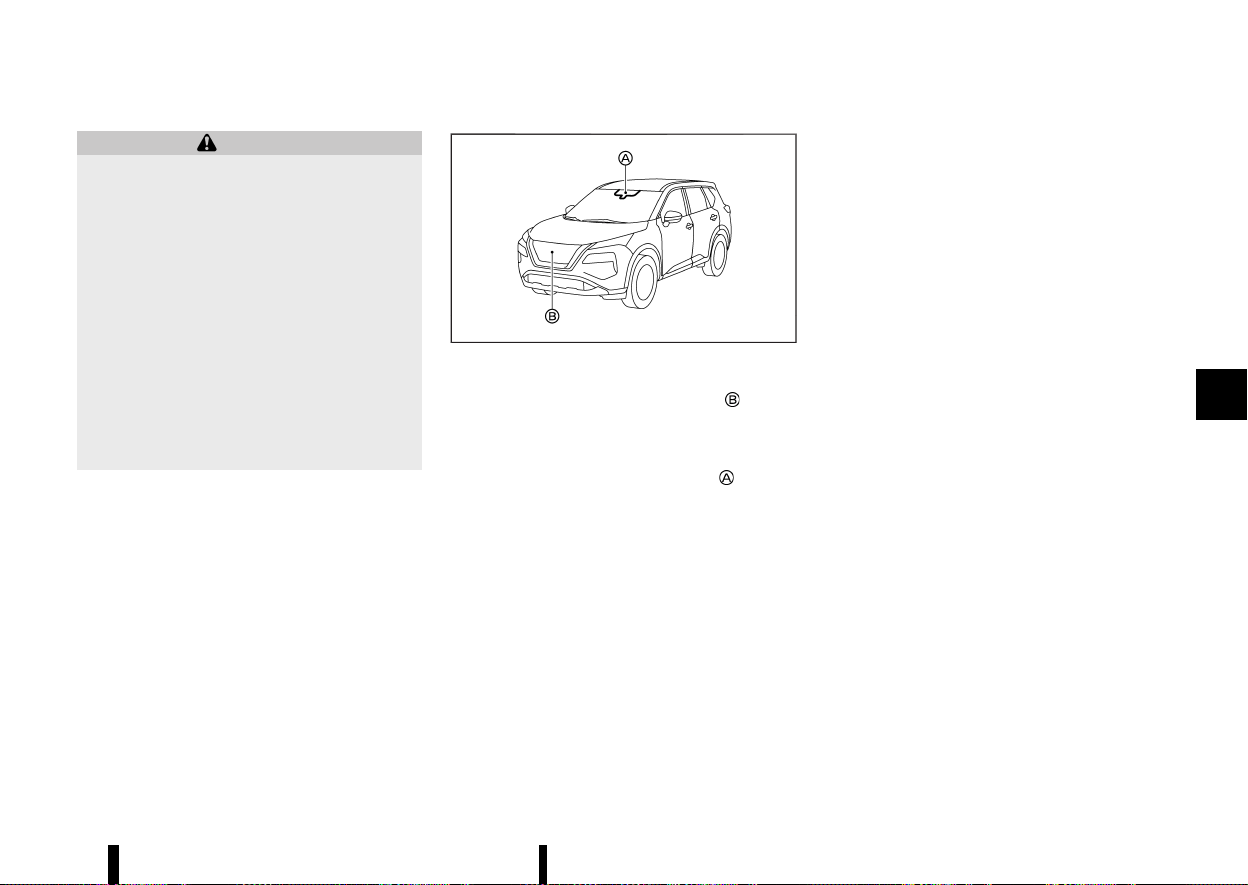
(363,1)
MEVT33A1-1E697A6A-7B87-4B8D-B8B3-D4416CD669CD
WARNING
Failure to follow the warnings and instructions
for proper use of the Intelligent Emergency
Braking with Pedestrian Detection system
could result in serious injury or death.
* The Intelligent Emergency Braking with
Pedestrian Detection system is a supple-
mental aid to the driver. It is not a
replacement for the driver’s attention to
traffic conditions or responsibility to drive
safely. It cannot prevent accidents due to
carelessness or dangerous driving tech-
niques.
* The Intelligent Emergency Braking with
Pedestrian Detection system does not
function in all driving, traffic, weather and
road conditions.
The Intelligent Emergency Braking with Pedestrian
Detection system can assist the driver when there
is a risk of a forward collision with
* a vehicle ahead in the travelling lane
* a pedestrian ahead in the travelling lane
* a cyclist ahead in the travelling lane (where
fitted)
Junction assist (where fitted) can assist the driver
when there is a risk of a forward collision
* When you turn right or left and cross the path
of an oncoming vehicle.
* When you turn right or left, a pedestrian is
detected in the forward direction and is
expected to enter your vehicle’s path.
MWAF0644X
The Intelligent Emergency Braking with Pedestrian
Detection system uses a radar sensor
located
on the front of the vehicle to measure the distance
to the vehicle ahead in the same lane.
For pedestrians and cyclists, the Intelligent Emer-
gency Braking system uses a camera
installed
behind the windscreen in addition to the radar
sensor.
Starting and driving 359
INTELLIGENT EMERGENCY BRAKING
WITH PEDESTRIAN DETECTION SYSTEM
INTELLIGENT EMERGENCY BRAKING
WITH PEDESTRIAN DETECTION SYSTEM
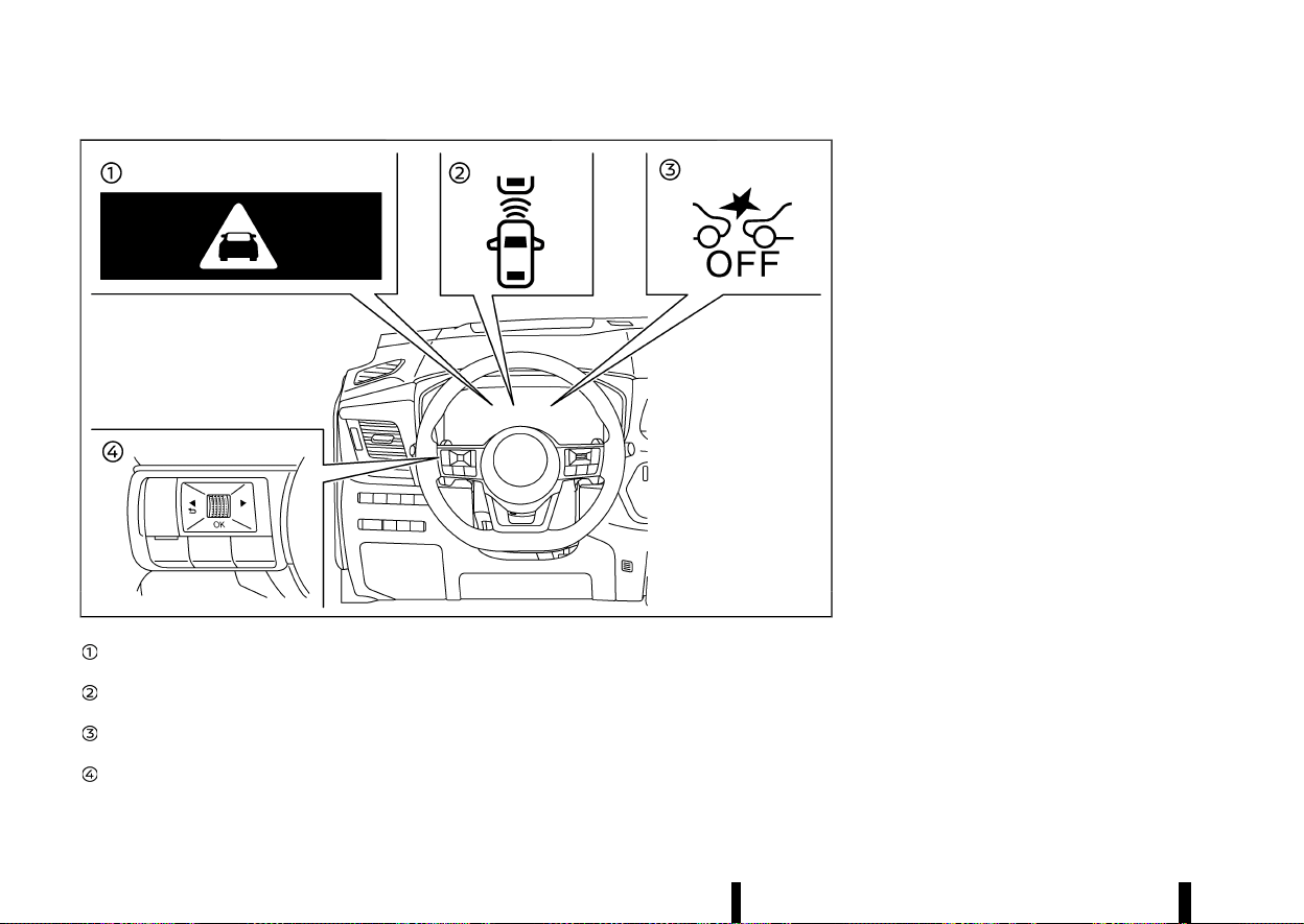
(364,1)
360 Starting and driving
MWAF0429X
Intelligent Emergency Braking emergency
warning indicator
Vehicle ahead detection indicator (on the
vehicle information display)
Intelligent Emergency Braking system OFF
warning light (on the meter panel)
Steering-wheel-mounted controls (left side)
INTELLIGENT EMERGENCY BRAKING
WITH PEDESTRIAN DETECTION SYSTEM
OPERATION
MEVT33A1-14634759-5958-4676-8862-1779DFEC01DC
If a risk of a forward collision is detected, the
Intelligent Emergency Braking with Pedestrian
Detection system will firstly provide the warning
to the driver by flashing the vehicle ahead detec-
tion indicator (yellow) in the vehicle information
display and providing an audible alert, and causing
the brake system to pulse (quickly partially apply).
In addition, the system applies partial braking.
If the driver applies the brakes quickly and force-
fully , but the system detects that there is still the
possibility of a forward collision, the system will
automatically increase the braking force.
If the driver does not take action, the Intelligent
Emergency Braking with Pedestrian Detection
system issues the second visual warning (flashing
red and white) and audible warning. Then the
system applies partial braking when the condition
to do so is satisfied.
If the risk of a collision becomes imminent, the
Intelligent Emergency Braking with Pedestrian
Detection system applies harder braking automa-
tically.
The Intelligent Emergency Braking with Pedestrian
Detection system will function when your vehicle is
driven at speeds above approximately 5 km/h (3
MPH).
For the pedestrian and cyclists detection function
(where fitted), the Intelligent Emergency Braking
with Pedestrian Detection system operates at
speeds between 10 - 80 km/h (6 - 50 MPH).
Junction assist (where fitted) operates at your
vehicle speeds between 10 - 25 km/h (6 – 16 MPH).
When turning left or right, the turn signal must be
activated to ensure that oncoming vehicles can be
detected by junction assist.
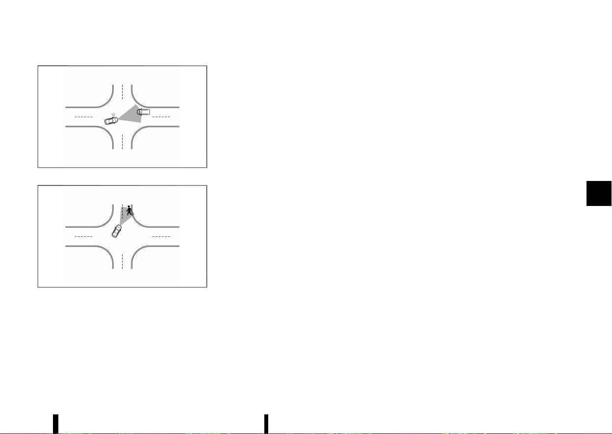
(365,1)
MWAF1019X
Junction assist for oncoming vehicle
MWAF1020X
Junction assist for pedestrian
NOTE:
* The vehicle’s brake lights come on when
braking is performed by the Intelligent
Emergency Braking with Pedestrian Detec-
tion system.
* When the Intelligent Emergency Braking
with Pedestrian Detection system detects
an obstacle in the path of the vehicle and
displays the Intelligent Emergency Braking
warning, a noise may be heard from the
engine compartment as the vehicle primes
the brakes to improve response time.
Depending on vehicle speed and distance to the
vehicle, pedestrian or cyclists ahead, as well as
driving and roadway conditions, the system may
help the driver avoid a forward collision or may
help mitigate the consequences of a collision
should one be unavoidable.
If the driver is handling the steering wheel, accel-
erating or braking, the Intelligent Emergency
Braking with Pedestrian Detection system will
function later or will not function.
The automatic braking will cease under the
following conditions:
* When the steering wheel is turned as far as
necessary to avoid a collision.
* When the accelerator pedal is depressed.
* When there is no longer a vehicle, pedestrian
detected ahead.
If the Intelligent Emergency Braking with Pedes-
trian Detection system has stopped the vehicle,
the vehicle will remain at a standstill for approxi-
mately 2 seconds before the brakes are released.
When the brake pedal is depressed while the brake
is applied by the system, you may feel the pedal
effort is changed and may hear a sound and
vibration noise. This is normal and does not
indicate a malfunction. In addition, the braking
force can be increased by adding the pedal effort.
Starting and driving 361
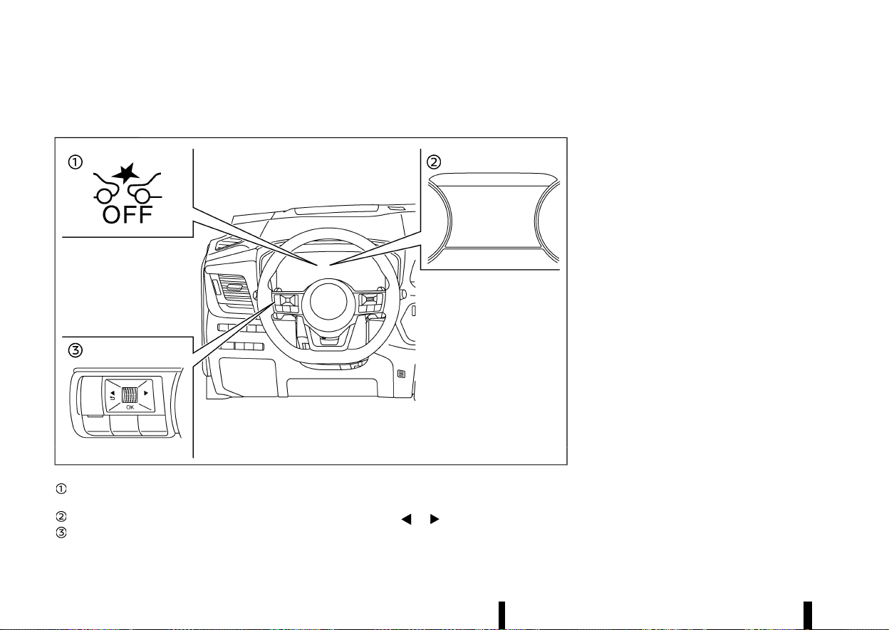
(366,1)
362 Starting and driving
TURNING THE INTELLIGENT EMERGENCY BRAKING WITH PEDESTRIAN DETECTION
SYSTEM ON/OFF
MEVT33A1-E1073118-7F8E-4B45-8302-E7059CCE1F9F
MWAF0430X
Intelligent Emergency Braking system OFF
warning light (on the meter panel)
Vehicle information display
Steering-wheel-mounted controls (left side)
Perform the following steps to turn the Intelligent
Emergency Braking with Pedestrian Detection
system on or off.
1. Push the
button until [Settings]
appears in the vehicle information display
and then push the scroll dial. Use the scroll
dial to select [Driver Assistance]. Then push the
scroll dial.
2. Type A:
Select [Emergency Brake] and push the scroll
dial. Then select [Front] and push the scroll dial
to turn the system on or off.
Type B:
Select [Emergency Brake] and push the scroll
dial to turn the system on or off.
When the Intelligent Emergency Braking with
Pedestrian Detection system is turned off, the
Intelligent Emergency Braking system OFF warn-
ing light illuminates.
NOTE:
* Disabling the Vehicle Dynamic Control (VDC)/
Electronic Stability Programme (ESP) system
causes the Intelligent Emergency Braking
with Pedestrian Detection system to be-
come unavailable regardless of settings
selected in the vehicle information display.
* The Intelligent Emergency Braking with
Pedestrian Detection system will be auto-
matically turned ON when the engine is
restarted.
* The Intelligent Forward Collision Warning
system is integrated into the Intelligent
Emergency Braking system. There is not a
separate selection for the Intelligent For-
ward Collision Warning system. When the
Intelligent Emergency Braking with Pedes-
trian Detection system is turned off, the
Intelligent Forward Collision Warning system
is also turned off.
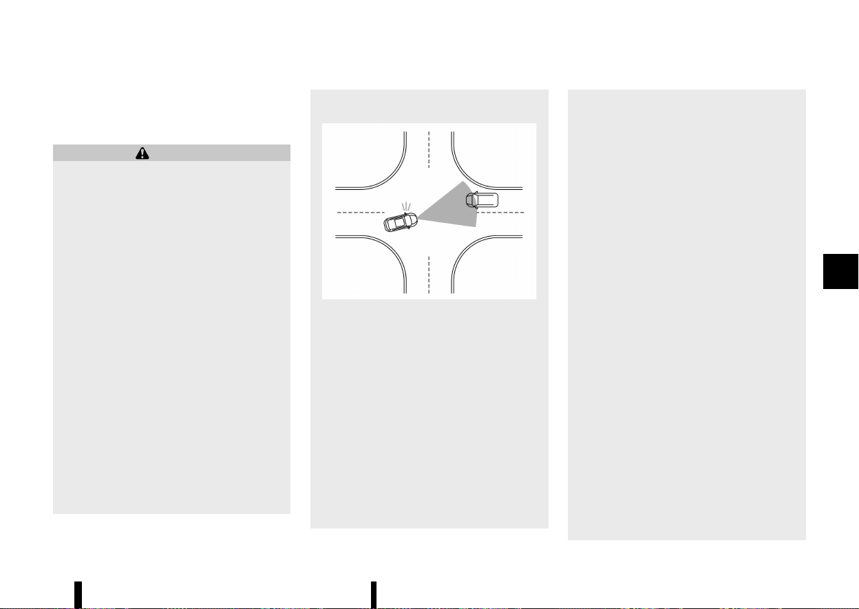
(367,1)
INTELLIGENT EMERGENCY BRAKING
WITH PEDESTRIAN DETECTION SYSTEM
LIMITATIONS
MEVT33A1-D3D63CC2-D735-4134-ACD0-5A1C3F3BEC19
WARNING
Listed below are the system limitations for the
Intelligent Emergency Braking with Pedestrian
Detection system. Failure to operate the vehi-
cle in accordance with these system limita-
tions could result in serious injury or death.
* The Intelligent Emergency Braking with
Pedestrian Detection system cannot de-
tect all vehicles, pedestrians or cyclists
under all conditions.
* The Intelligent Emergency Braking with
Pedestrian Detection system does not
detect the following objects:
— Small pedestrians (including small
children) and animals.
— Pedestrians in wheelchairs or using
mobile transport such as scooters,
child-operated toys, or skateboards.
— Pedestrians who are seated or other-
wise not in a full upright standing or
walking position.
— Crossing vehicles.
— Obstacles on the roadside.
— Parked vehicles.
* Junction Assist (where fitted) does not
detect the following:
— Oncoming vehicle in front of your
vehicle.
MWAF1021X
* The Intelligent Emergency Braking with
Pedestrian Detection system has some
performance limitations.
— If a stationary vehicle is in the vehicle’s
path, the Intelligent Emergency Brak-
ing with Pedestrian Detection system
will not function when the vehicle is
driven at speeds over approximately
100 km/h (62 MPH).
* The Intelligent Emergency Braking with
Pedestrian Detection system may not
function for pedestrians and cyclists (mod-
els with cyclist detection) in darkness or in
tunnels, even if there is street lighting in
the area.
* The Intelligent Emergency Braking with
Pedestrian Detection system may not
function if the vehicle ahead is narrow (for
example, a motorcycle).
* The Intelligent Emergency Braking with
Pedestrian Detection system may not
function if the speed difference between
the two vehicles is too small.
* The Intelligent Emergency Braking with
Pedestrian Detection system may not ap-
ply braking when the vehicle speed is high
in the operation range.
* For pedestrians, the Intelligent Emergency
Braking with Pedestrian Detection system
may not issue the first warning.
* The Intelligent Emergency Braking with
Pedestrian Detection system may not
function properly or detect a vehicle, pe-
destrian or cyclist (models with cyclist
detection) ahead in the following condi-
tions:
— In dark or dimly lit conditions, such as
at night or in tunnels, including cases
where your vehicle’s headlights are off
or dim, or the tail lights of the vehicle
ahead are off.
— When the direction of the camera is
misaligned.
— Poor visibility (conditions such as rain,
snow, fog, dust storms, sandstorms,
and road spray from other vehicles).
— Driving on a steep downhill slope or
roads with sharp curves.
— Driving on a bumpy road surface, such
as an uneven dirt road.
Starting and driving 363
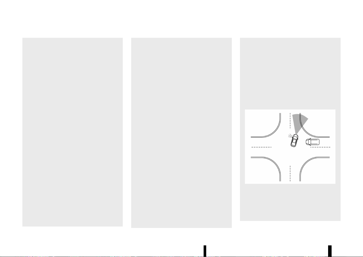
(368,1)
364 Starting and driving
— If dirt, ice, snow or other material is
covering the radar sensor area.
— Interference by other radar sources.
— The camera area of windscreen is
fogged up, or covered with dirt, water
drops, ice, snow, etc.
— Strong light (for example, sunlight or
high beams from oncoming vehicles)
enters the front camera. Strong light
causes the area around the pedestrian
or cyclist to be cast in a shadow,
making it difficult to see.
— A sudden change in brightness occurs.
(For example, when the vehicle enters
or exits a tunnel or a shaded area or
lightning flashes.)
— The poor contrast of a person to the
background, such as having clothing
colour or pattern which is similar to
the background.
— The pedestrian’s profile is partially
obscured or unidentifiable; for exam-
ple, due to transporting luggage,
pushing a stroller, wearing bulky or
very loose-fitting clothing or acces-
sories, or being in a unique posture
(such as raising hands).
— When your vehicle’s position or move-
ment is changed quickly or signifi-
cantly (for example, lane change,
turning vehicle, abrupt steering, sud-
den acceleration or deceleration).
— When your vehicle or the vehicle,
pedestrian or cyclist ahead moves
quickly or significantly such that the
system cannot detect and react in
time (for example, pedestrian moving
quickly toward the vehicle at close
range, vehicle cutting in, changing
lanes, making a turn, steering
abruptly, sudden acceleration or de-
celeration).
— When the vehicle, pedestrian or cyclist
is offset from the vehicle’s forward
path.
— If the speed difference between the
two vehicles is small.
— For approximately 15 seconds after
starting the engine.
— If the vehicle ahead or oncoming
vehicle has a unique or unusual shape,
extremely low or high clearance
heights, or unusual cargo loading or
is narrow (for example, a motorcycle).
— When the vehicle, pedestrian or cyclist
is located near a traffic sign, a reflec-
tive area (for example, water on road),
or is in a shadow.
— When multiple pedestrians or cyclists
are grouped together.
— When the view of the pedestrian or
cyclist is obscured by a vehicle or
other object.
— While towing a trailer or other vehicle.
* Junction Assist (where fitted) may not
operate properly or detect a oncoming
vehicle or pedestrian in the following con-
ditions:
— When driving in a traffic lane sepa-
rated by more than 2 lanes from
oncoming vehicles while making a
right/left turn.
— When not heading directly towards an
oncoming vehicle during a right/left
turn.
— When crossing an oncoming vehicle
lane and an oncoming vehicle ap-
proaches.
MWAF1024X
— When turning sharply or on a very wide
curve.
— When the centre line is not recognised
by the system.
— When there are a number of oncoming
vehicles following each other in a row.
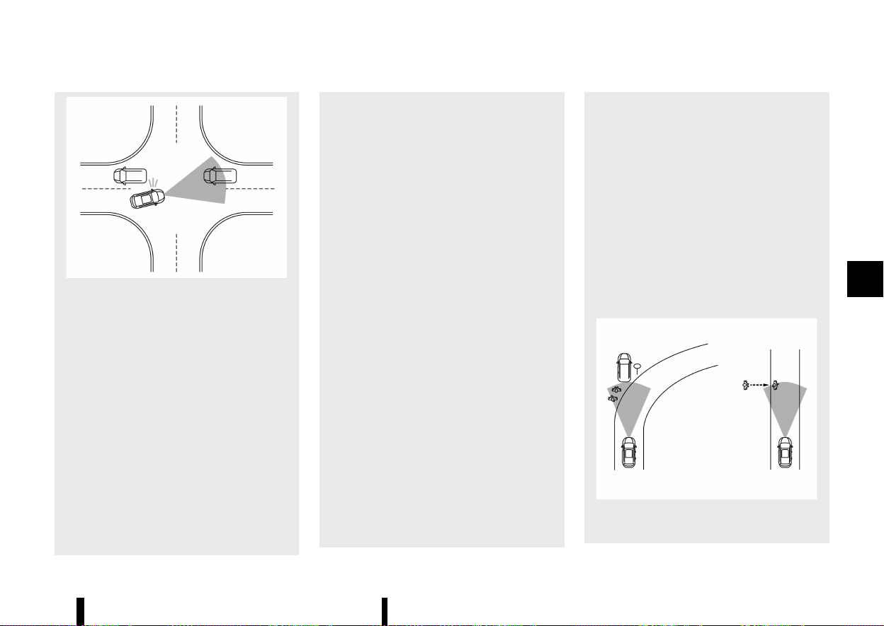
(369,1)
MWAF1025X
— When the lane is wider or narrower
than normal.
— When the centre line is located close to
a road marker.
* The system performance may degrade in
the following conditions:
— The vehicle is driven on a slippery
road.
— The vehicle is driven on a slope.
— Excessively heavy baggage is loaded
in the rear seat or the cargo area of
your vehicle.
— When the Stop/Start system is active.
* The system is designed to automatically
check the sensor (radar and camera)’s
functionality, within certain limitations.
The system may not detect blockage of
sensor areas covered by ice, snow or
stickers, for example. In these cases, the
system may not be able to warn the driver
properly. Be sure that you check, clean and
clear sensor areas regularly.
* In some road and traffic conditions, the
Intelligent Emergency Braking with Pedes-
trian Detection system may unexpectedly
apply partial braking. When acceleration is
necessary, depress the accelerator pedal
to override the system.
* Excessive noise will interfere with the
warning chime sound, and the chime may
not be heard.
* Braking distances increase on slippery
surfaces.
* The Intelligent Emergency Braking with
Pedestrian Detection system may operate
when the following are similar to the out-
lines of pedestrians or cyclists (models
with cyclist detection), or if they are the
same size and position as a vehicle’s and
motorcycle’s tail lights.
— Paint, a shadow or a pattern on the
road, roadside or wall (including faded
and unusual road markings).
— A shape formed by road structures
ahead (such as tunnels, viaducts, traf-
fic sign, reflectors installed on the side
of vehicles, reflection sheets, and
guardrails), road side objects (trees,
buildings) and light sources.
— A shape formed by road side objects,
such as trees, lighting, shadows, or
buildings.
* The Intelligent Emergency Braking with
Pedestrian Detection system may keep
operating when the vehicle ahead is turn-
ing right or left.
* The Intelligent Emergency Braking with
Pedestrian Detection system may operate
when your vehicle is approaching and
passing a vehicle ahead.
* Depending on the road shape (curved road,
entrance and exit of the curve, winding
road, lane regulation, under construction,
etc.), the function may operate temporarily
for the oncoming vehicle in front of your
vehicle.
* The Intelligent Emergency Braking with
Pedestrian Detection system may react to:
MWAF1026X
— Objects on the roadside (traffic sign,
guardrail, pedestrian or cyclist, vehicle,
etc.).
Starting and driving 365

(370,1)
366 Starting and driving
— Objects above road (low bridge, traffic
sign, etc.).
— Objects on the road surface (railroad
track, grate, steel plate, etc.).
— Objects in the parking garage (beam,
etc.).
— Pedestrians, cyclists or motorcycles
approaching the travelling lane.
— Pedestrians and cyclists when driving
down narrow alleys, for example.
— Pedestrians and cyclists who tem-
porarily move into or approach the
driving lane to avoid obstacles at the
side of the road.
— Objects on the road such as trees.
— Vehicles, pedestrians, cyclists, motor-
cycles or objects in adjacent lane or
close to the vehicle.
— Oncoming pedestrians or cyclists.
* Junction Assist (where fitted) may react to
the following while making a right/left
turn:
— When an oncoming vehicle or a cross-
ing pedestrian has already exited the
path of your vehicle.
— If you are closely in front of an oncom-
ing vehicle or a crossing pedestrian.
— When an oncoming vehicle or a cross-
ing pedestrian stops before entering
the path of your vehicle.
— When an oncoming vehicle turns right
or left in front of your vehicle.
* Junction Assist (where fitted) may also
react to the following:
— When oncoming vehicle movement
cannot be predicted due to sudden
left/right turns or deceleration of the
oncoming vehicles.
* Braking distances increase on slippery
surfaces.
* Excessive noise will interfere with the
warning chime and the chime may not be
heard.

(371,1)
MSSD0253
When driving on some roads, such as winding, hilly,
curved, narrow roads, or roads which are under
construction or on a slope, the sensor may detect
vehicles in a different lane, or may temporarily not
detect a vehicle travelling ahead. This may cause
the system to work inappropriately.
The detection of vehicles may also be affected by
vehicle operation (steering manoeuvre or travel-
ling position in the lane, etc.) or vehicle condition. If
this occurs, the system may warn you by
blinking the system indicator and sounding the
chime unexpectedly. You will have to manually
control the proper distance to the vehicle
travelling ahead.
SYSTEM TEMPORARILY UNAVAILABLE
MEVT33A1-6DEACBF5-FBF9-460C-8966-2BA4DBBE62B2
Condition A
MEVT33A1-74213B11-0446-4041-9078-7D719817D93C
In the following conditions, the Intelligent Emer-
gency Braking system OFF warning light blinks and
the system will be turned off automatically.
* The camera area of the windscreen is misted
or frozen.
* The camera area of the windscreen is con-
tinuously covered with dirt, etc.
Action to take:
Check that the windscreen is clean and free from
ice/mist in front of the camera. If necessary,
operate the Max defogging/defrosting function
or heated windscreen (where fitted) to clear. This
may take several minutes.
When the above condition no longer exists, the
Intelligent Emergency Braking with Pedestrian
Detection system will resume automatically.
Condition B
MEVT33A1-6A7423C6-B979-49A4-95CF-059AA9FEF668
In the following conditions, the Intelligent Emer-
gency Braking system OFF warning light will blink,
with no accompanying message in the vehicle
information display.
* Strong light is shining onto the front of the
vehicle.
* The cabin temperature is over approximately
40 °C (104 °F) in direct sunlight.
* The radar sensor can receive interference
from other radar sources and excessive reflec-
tion from other vehicles (for example, when
travelling past vehicles in a traffic jam).
* The camera unit detects that it is not correctly
aligned.
Action to take:
None. When the above condition no longer exists,
the Intelligent Emergency Braking with Pedestrian
Detection system will resume automatically.
NOTE:
If the inside of the windscreen in front of the
camera is misted or frozen, it will take a period
of time to for it to clear after the air conditioner
turns on. If dirt appears in this area, it is
recommended you visit a NISSAN dealer or
qualified workshop.
Condition C
MEVT33A1-DF6072C9-6D96-4927-B803-9E324390D570
In the following condition, the Intelligent Emer-
gency Braking system OFF warning light will
illuminate and the [Temporarily Disabled Front
Radar Blocked] warning message will appear in
the vehicle information display.
* The sensor area on the front of the vehicle is
covered with dirt or is obstructed
Action to take:
If the warning light illuminates, stop the vehicle in a
safe place and turn the engine off. Check if the
sensor area at the front of the vehicle, and remove
the blocking material. Restart the engine. If the
Starting and driving 367
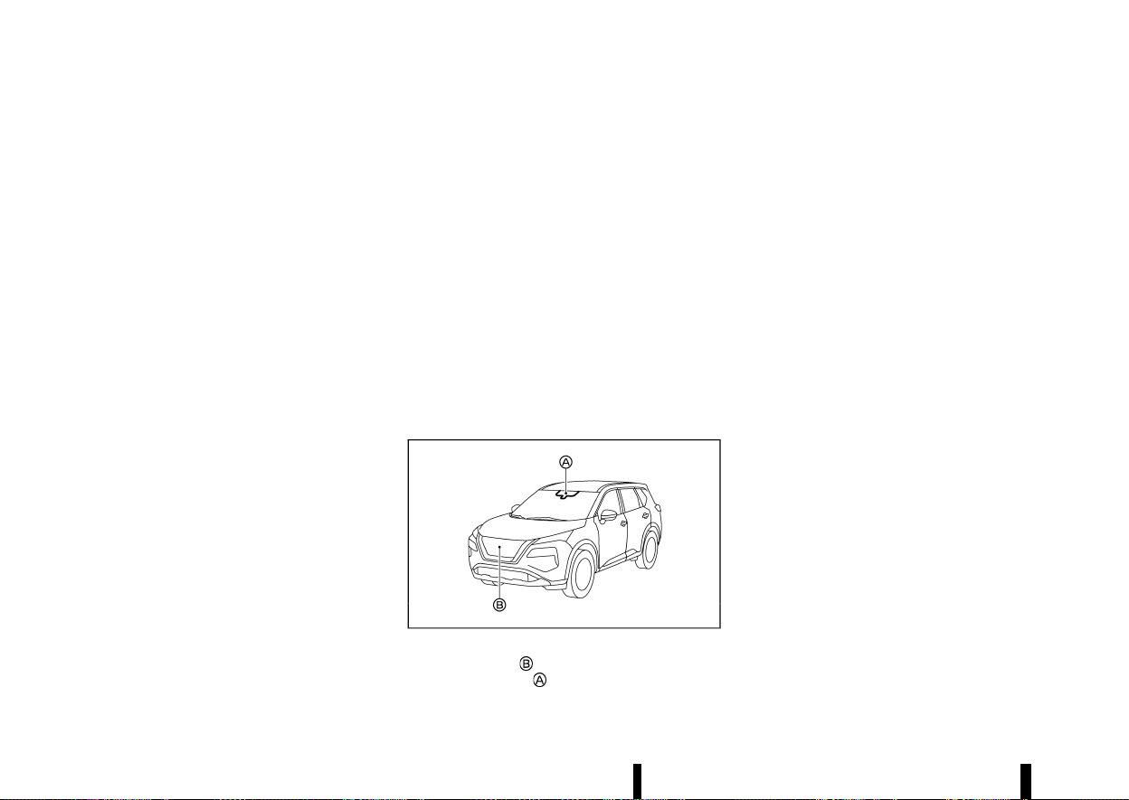
(372,1)
368 Starting and driving
warning light continues to illuminate after driving
for a few minutes, have the Intelligent Emergency
Braking with Pedestrian Detection system
checked. It is recommended you visit a NISSAN
dealer or qualified workshop for this service.
Condition D
MEVT33A1-9B00E14D-7311-4FFC-93B0-0C318233F914
In the following condition, the Intelligent Emer-
gency Braking system OFF warning light will
illuminate and the [Temporarily Disabled Front
Radar Blocked] warning message will appear in
the vehicle information display.
* When driving on roads with limited road
structures or buildings (for example, long
bridges, deserts, snow fields, driving next to
long walls).
Action to take:
When the above conditions no longer exist, the
Intelligent Emergency Braking with Pedestrian
Detection system will resume automatically.
Condition E
MEVT33A1-0DC812AF-A7FD-4373-88DD-7100D42B0525
When the Vehicle Dynamic Control (VDC)/Electro-
nic Stability Programme (ESP) system is turned
OFF, the Intelligent Emergency Braking system
braking will not operate. In this case only the visible
and audible warning operates. The Intelligent
Emergency Braking system OFF warning light will
illuminate.
Action to take
When the VDC/ESP system is ON, the Intelligent
Emergency Braking with Pedestrian Detection
system will resume automatically.
SYSTEM MALFUNCTION
MEVT33A1-47FE30D4-2477-4074-88FC-E8F10D7D4BA5
If the Intelligent Emergency Braking with Pedes-
trian Detection system malfunctions, it will be
turned off automatically, a chime will sound, the
Intelligent Emergency Braking system OFF warn-
ing light (yellow) will illuminate and the [System
fault See Owner’s Manual] warning message will
appear in the vehicle information display.
Action to take:
If the warning light (yellow) comes on, stop the
vehicle in a safe location. Turn the engine off and
restart the engine. If the warning light continues to
illuminate, have the Intelligent Emergency Braking
with Pedestrian Detection system checked. It is
recommended that you visit a NISSAN dealer or
qualified workshop for this service.
SYSTEM MAINTENANCE
MEVT33A1-8CA11B9B-B1C6-4337-B8E4-D8AD5460BC38
MWAF0644X
The radar sensor is located on the front of the
vehicle. The camera
is located on the upper side
of the windscreen.
To keep the Intelligent Emergency Braking with
Pedestrian Detection system operating properly,
be sure to observe the following:
* Always keep the sensor area on the front of
the vehicle and windscreen clean.
* Do not strike or damage the areas around the
sensors (ex. bumper, windscreen).
* Do not cover or attach stickers or similar
objects on the front of the vehicle near the
sensor area. This could cause failure or mal-
function.
* Do not attach metallic objects near the radar
sensor area (brush guard, etc.). This could
cause failure or malfunction.
* Do not place reflective materials, such as white
paper or a mirror, on the instrument panel.
The reflection of sunlight may adversely affect
the camera unit’s detection capability.
* Do not alter, remove or paint the front of the
vehicle near the sensor area. Before customis-
ing or restoring the sensor area, it is recom-
mended that you visit a NISSAN dealer or
qualified workshop.
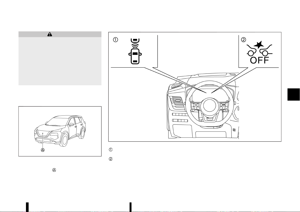
(373,1)
MEVT33A1-DD09929F-5EE9-4DE3-8ADD-A90FC8F483A1
WARNING
Failure to follow the warnings and instructions
for proper use of the Intelligent Forward
Collision Warning system could result in ser-
ious injury or death.
* The Intelligent Forward Collision Warning
system helps warn the driver before a
collision but will not avoid a collision. It is
the driver’s responsibility to stay alert,
drive safely and be in control of the vehicle
at all times.
The Intelligent Forward Collision Warning system
can help alert the driver when there is a sudden
braking of a second vehicle travelling in front of
the vehicle ahead in the same lane.
MWAF0646X
The Intelligent Forward Collision Warning system
uses a radar sensor
located on the front of the
vehicle to measure the distance to a second
vehicle ahead in the same lane.
MWAF0432X
Vehicle ahead detection indicator (on the
vehicle information display)
Intelligent Emergency Braking system OFF
warning light (on the meter panel)
Starting and driving 369
INTELLIGENT FORWARD COLLISION WARNING
INTELLIGENT FORWARD COLLISION WARNING
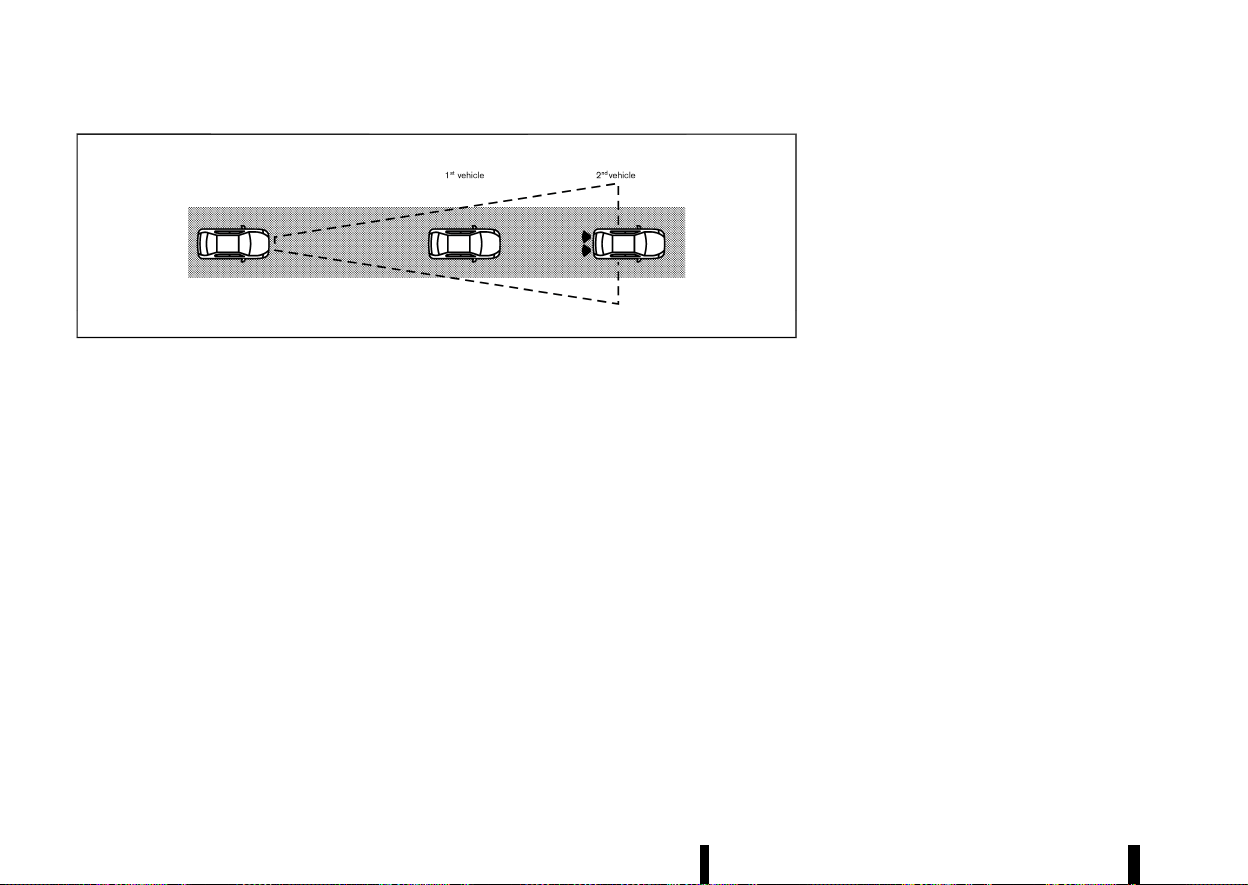
(374,1)
370 Starting and driving
MJVS0294X
INTELLIGENT FORWARD COLLISION
WARNING SYSTEM OPERATION
MEVT33A1-57AB9B2D-DD18-4FE3-84DE-E2CD45ED8B35
The Intelligent Forward Collision Warning system
operates at speeds above approximately 5 km/h (3
MPH).
If there is a potential risk of a forward collision, the
Intelligent Forward Collision Warning system will
warn the driver by blinking the vehicle ahead
detection indicator, and sounding an audible alert.
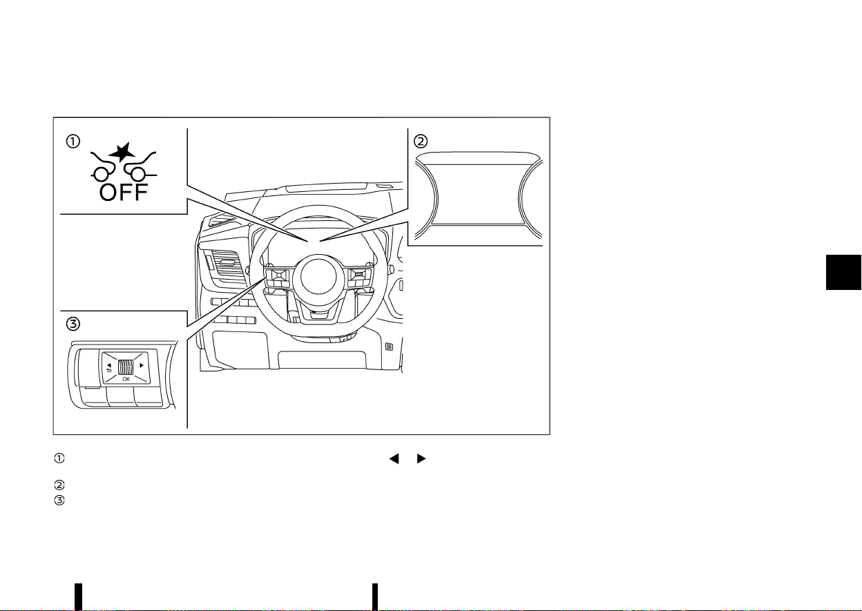
(375,1)
TURNING THE INTELLIGENT FORWARD COLLISION WARNING SYSTEM ON/OFF
MEVT33A1-F0C84970-5CA4-439E-A63F-8F9090E635CD
MWAF0430X
Intelligent Emergency Braking system OFF
warning light (on the meter panel)
Vehicle information display
Steering-wheel-mounted controls (left side)
Perform the following steps to turn the Intelligent
Forward Collision Warning system on or off.
1. Push the
button until [Settings]
appears in the vehicle information display
and then push the scroll dial. Use the scroll
dial to select [Driver Assistance]. Then push the
scroll dial.
2. Type A:
Select [Emergency Brake] and push the scroll
dial. Then select [Front] and push the scroll dial
to turn the system on or off.
Type B:
Select [Emergency Brake] and push the scroll
dial to turn the system on or off.
When the Intelligent Forward Collision Warning
system is turned off, the Intelligent Emergency
Braking system OFF warning light (yellow) illumi-
nates.
NOTE:
* The Intelligent Forward Collision Warning
system will be automatically turned on
when the engine is restarted.
* The Intelligent Forward Collision Warning
system is integrated into the Intelligent
Emergency Braking system. There is not a
separate selection for the Intelligent For-
ward Collision Warning system. When the
Intelligent Emergency Braking system is
turned off, the Intelligent Forward Collision
Warning system is also turned off.
Starting and driving 371

(376,1)
372 Starting and driving
INTELLIGENT FORWARD COLLISION
WARNING SYSTEM LIMITATIONS
MEVT33A1-63341D8F-7FC5-4938-8058-11084466DEC5
MJVS0295X
Illustration A
MJVS0296X
Illustration B
MJVS0297X
Illustration C
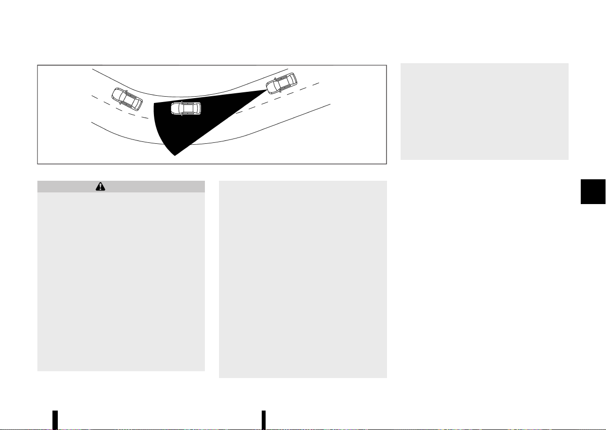
(377,1)
MJVS0298X
Illustration D
WARNING
Listed below are the system limitations for the
Intelligent Forward Collision Warning system.
Failure to operate the vehicle in accordance
with these system limitations could result in
serious injury or death.
* The Intelligent Forward Collision Warning
system cannot detect all vehicles under all
conditions.
* The radar sensor does not detect the
following objects:
— Pedestrians, animals or obstacles in
the roadway
— Oncoming vehicles
— Crossing vehicles
* (Illustration A) The Intelligent Forward Col-
lision Warning system does not function
when a vehicle ahead is a narrow vehicle,
such as a motorcycle.
* The radar sensor may not detect a vehicle
ahead in the following conditions:
— Snow or heavy rain
— Dirt, ice, snow or other material cover-
ing the radar sensor
— Interference by other radar sources
— Snow or road spray from travelling
vehicles.
— Driving in a tunnel
— Towing a trailer
* (Illustration B) When the vehicle ahead is
being towed.
* (Illustration C) When the distance to the
vehicle ahead is too close, the beam of the
radar sensor is obstructed.
* (Illustration D) When driving on a steep
downhill slope or roads with sharp curves.
* The system is designed to automatically
check the sensor’s functionality, within
certain limitations. The system may not
detect some forms of obstruction of the
sensor area such as ice, snow, stickers, for
example. In these cases, the system may
not be able to warn the driver properly. Be
sure that you check, clean and clear the
sensor area regularly.
* Excessive noise will interfere with the
warning chime sound, and the chime may
not be heard.
Starting and driving 373
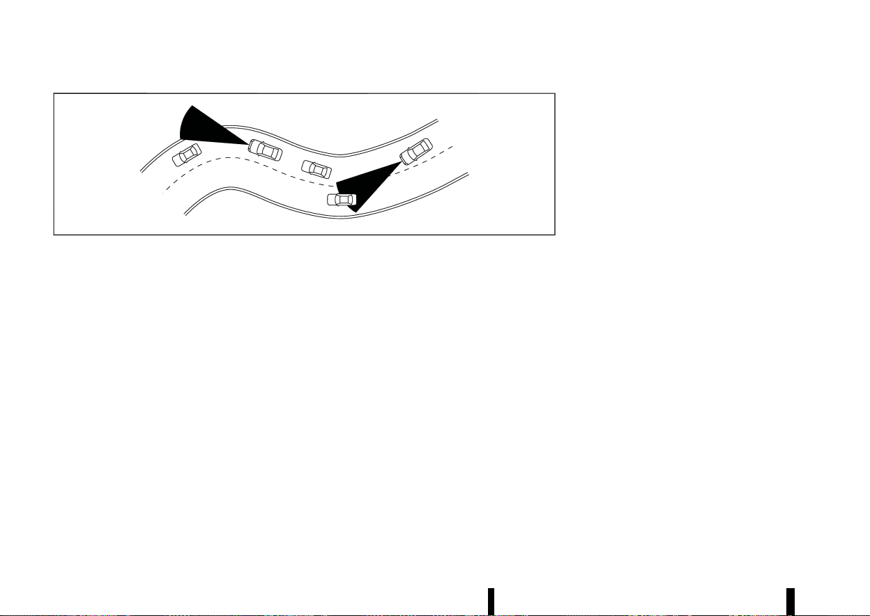
(378,1)
374 Starting and driving
MSSD0253
When driving on some roads, such as winding, hilly,
curved, narrow roads, or roads which are under
construction, the radar sensor may detect vehicles
in a different lane, or may temporarily not detect a
vehicle travelling ahead. This may cause the
Intelligent Forward Collision Warning system to
work inappropriately.
The detection of vehicles may also be affected by
vehicle operation (steering manoeuvre or travel-
ling position in the lane, etc.) or vehicle condition. If
this occurs, the system may warn you by
blinking the vehicle ahead detection indicator
and sounding the chime unexpectedly. You will
have to manually control the proper distance
away from the vehicle travelling ahead.
SYSTEM TEMPORARILY UNAVAILABLE
MEVT33A1-61FC37A3-8655-448B-9D12-5CDC96B32874
Condition A
MEVT33A1-F5FFA79B-EA98-41B1-9FF5-1044BE196F95
When the radar sensor picks up interference from
another radar source, making it impossible to
detect a vehicle ahead, the Intelligent Forward
Collision Warning system is automatically turned
off. The Intelligent Emergency Braking system OFF
warning light (yellow) will flash.
Action to take:
When the above conditions no longer exist, the
Intelligent Forward Collision Warning system will
resume automatically.
Condition B
MEVT33A1-D5336B1E-8EA8-4DFB-B46F-4C73988D0BDE
Under the following conditions, making it impos-
sible to detect a vehicle ahead, the Intelligent
Forward Collision Warning system is automatically
turned off.
The Intelligent Emergency Braking system OFF
warning light (yellow) will flash and the [Tempora-
rily Disabled Front Radar Blocked] warning mes-
sage will appear in the vehicle information display.
* When the sensor area of the front of the
vehicle is covered with dirt or is obstructed
Action to take:
If the warning light (yellow) flashes, stop the
vehicle in a safe place, push the park button to
engage the P (Park) position and turn the engine
off. Clean the radar cover on the front of the
vehicle with a soft cloth, and restart the engine. If
the warning light continues to illuminate, have the
Intelligent Forward Collision Warning system
checked. It is recommended you visit a NISSAN
dealer or qualified workshop for this service.
* When driving on roads with limited road
structures or buildings (for example, long
bridges, deserts, snow fields, driving next to
long walls)
Action to take:
When the above conditions no longer exist, the
Intelligent Forward Collision Warning system will
resume automatically.
SYSTEM MALFUNCTION
MEVT33A1-83445603-B261-4EF2-8FD3-2C68A869F5C2
If the Intelligent Forward Collision Warning system
malfunctions, it will be turned off automatically, a
chime will sound, the Intelligent Emergency Brak-
ing system OFF warning light (yellow) will illumi-
nate and the [System fault See Owner’s Manual]
warning message will appear in the vehicle in-
formation display.
Action to take:
If the warning light (yellow) illuminates, stop the
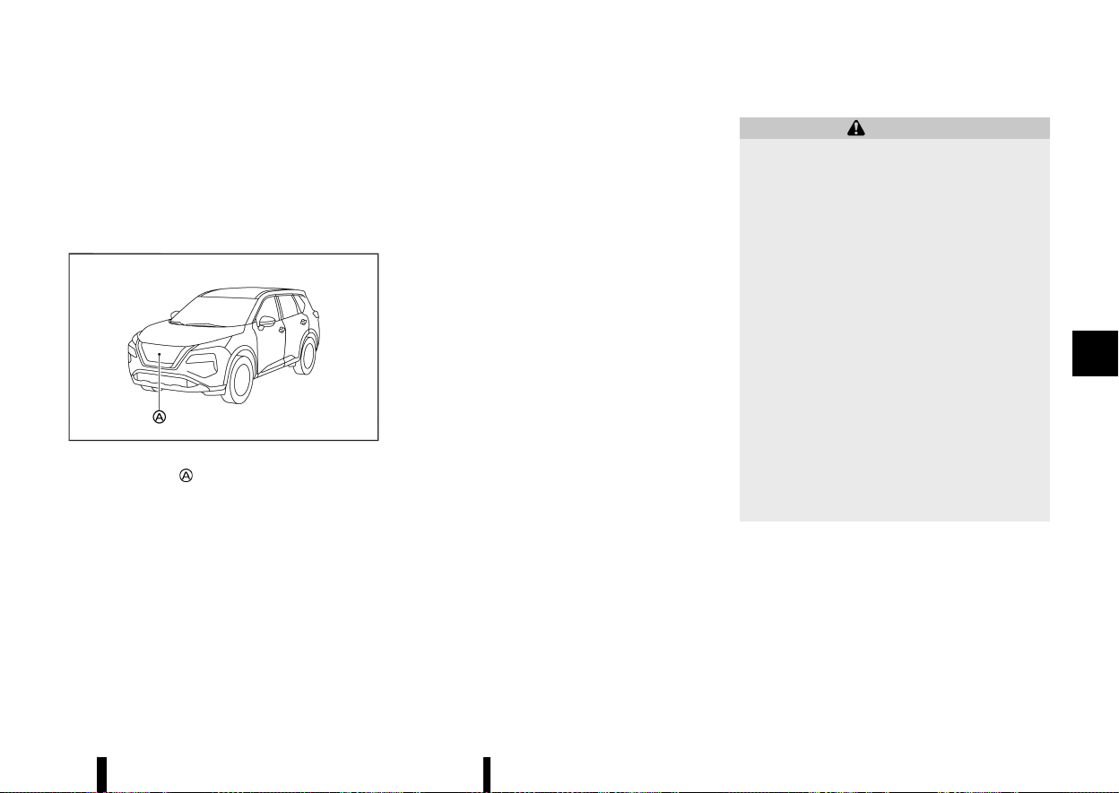
(379,1)
vehicle in a safe location. Turn the engine off and
restart the engine. If the warning light continues to
illuminate, have the Intelligent Forward Collision
Warning system checked. It is recommended you
visit a NISSAN dealer or qualified workshop for this
service.
SYSTEM MAINTENANCE
MEVT33A1-5A01E11F-872F-4B77-90FC-06587FED5B93
MWAF0646X
The radar sensor is located on the front of the
vehicle.
To keep the system operating properly, be sure to
observe the following:
* Always keep the sensor area on the front of
the vehicle clean.
* Do not strike or damage the areas around the
sensor.
* Do not cover or attach stickers or similar
objects on the front bumper near the sensor
area. This could cause failure or malfunction.
* Do not attach metallic objects near the sensor
area (brush guard, etc.). This could cause
failure or malfunction.
* Do not alter, remove or paint the front bumper.
It is recommended you contact a NISSAN
dealer or qualified workshop before customis-
ing or restoring the front bumper.
MEVT33A1-BFEA0EB0-AB09-4243-873F-201CAF92D7FF
WARNING
Failure to follow the warnings and instructions
for proper use of the Intelligent Driver Alert-
ness system could result in serious injury or
death.
* The Intelligent Driver Alertness system is
only a warning to inform the driver of a
potential lack of driver attention or drow-
siness. It will not steer the vehicle or
prevent loss of control.
* The Intelligent Driver Alertness system
does not detect and provide an alert of
the driver’s lack of attention or fatigue in
every situation.
* It is the driver’s responsibility to:
— Stay alert.
— Drive safely.
— Keep the vehicle in the travelling lane.
— Be in control of the vehicle at all times.
— Avoid driving when tired.
— Avoid distractions (texting, etc).
The Intelligent Driver Alertness system helps alert
the driver if the system detects a lack of attention
or driving fatigue.
The system monitors driving style and steering
behavior over a period of time, and it detects
changes from the normal pattern. If the system
detects that driver attention is decreasing over a
period of time, the system uses audible and visual
warnings to suggest that the driver take a break.
Starting and driving 375
INTELLIGENT DRIVER ALERT-
NESS (where fitted)
INTELLIGENT DRIVER ALERT-
NESS (where fitted)
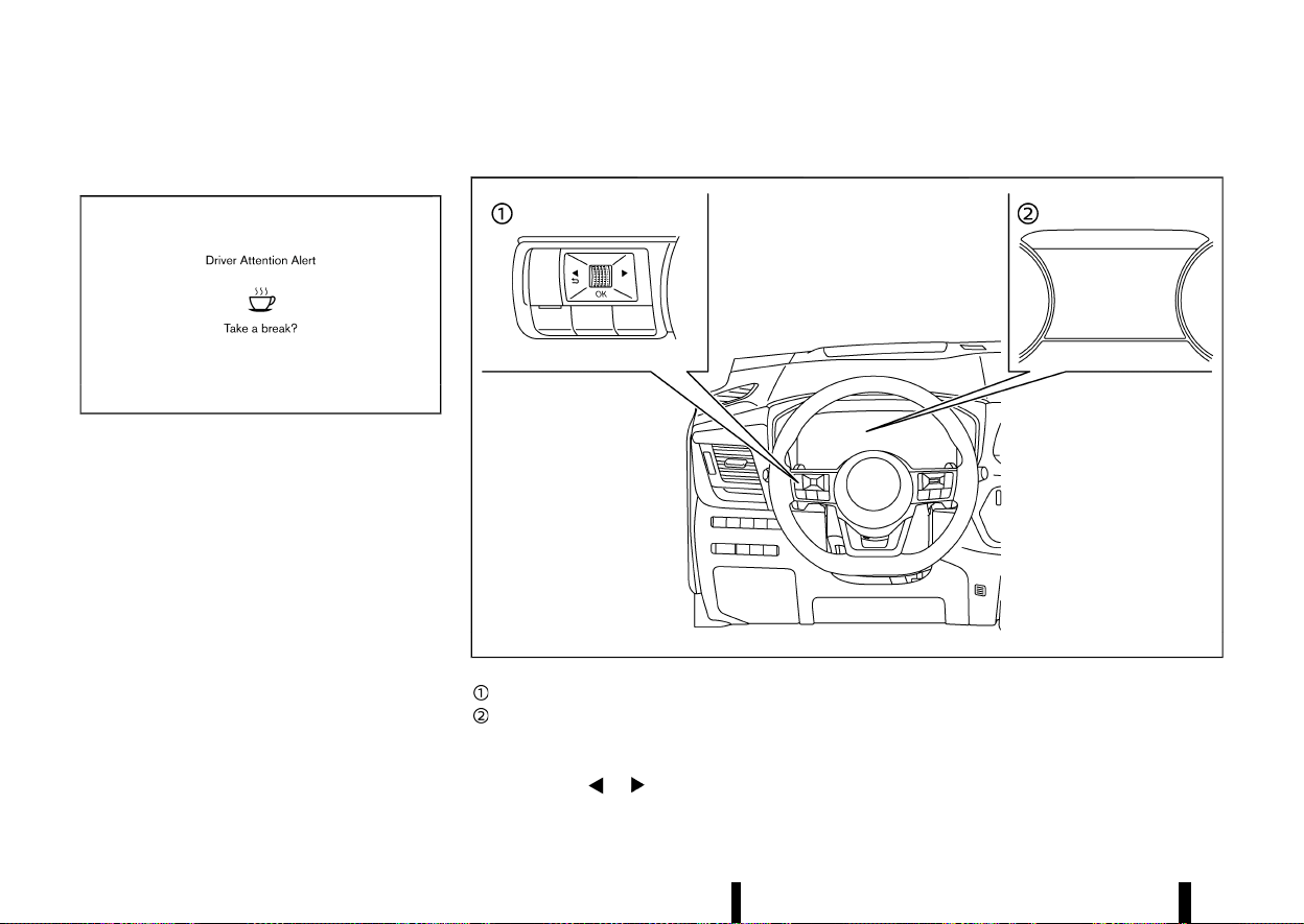
(380,1)
376 Starting and driving
INTELLIGENT DRIVER ALERTNESS SYS-
TEM OPERATION
MEVT33A1-931E82BB-FFAD-4D5E-89EA-1DFF02614387
MWBF0197X
Example
If the system detects driver fatigue or that driver
attention is decreasing, the message [Take a
break?] appears in the vehicle information display
and a chime sounds when the vehicle is driven at
speeds above 60 km/h (37 MPH).
The system continuously monitors driver attention
and can provide multiple warnings per trip.
The system resets and starts reassessing driving
style and steering behavior when the ignition
switch is cycled from the ON to the “OFF” position
and back to the ON position.
The system will not operate when Steering Assist
system (where fitted) is activated.
HOW TO ENABLE/DISABLE THE INTELLIGENT DRIVER ALERTNESS SYSTEM
MEVT33A1-0DE95B38-2BAF-4AEB-8F65-367687292CFE
MWAF0412X
Steering-wheel-mounted control (left side)
Vehicle information display
Perform the following steps to enable or disable
the Intelligent Driver Alertness system.
1. Push the
button until [Settings]
appears in the vehicle information display
and push the scroll dial. Use the scroll dial to
select [Driver Assistance]. Then push the scroll
dial.
2. Select [Driver Attention Alert] and push the
scroll dial.
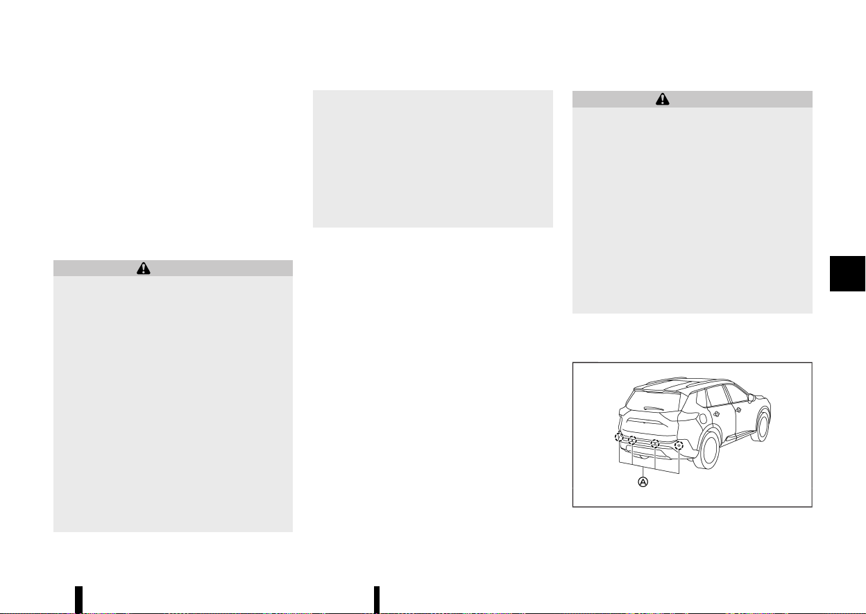
(381,1)
NOTE:
* The Intelligent Driver Alertness system will
automatically be turned on when the engine
is restarted.
* As long as Steering Assist (where fitted) is
activated, the Intelligent Driver Alertness
system will be deactivated.
Turning off Steering Assist reactivates the
Intelligent Driver Alertness system.
INTELLIGENT DRIVER ALERTNESS SYS-
TEM LIMITATIONS
MEVT33A1-7A0691C3-42E1-4EF8-8197-E99891D5DE73
WARNING
Listed below are the system limitations for the
Intelligent Driver Alertness system. Failure to
operate the vehicle in accordance with these
system limitations could result in serious injury
or death.
* The Intelligent Driver Alertness system
may not operate properly and may not
provide an alert in the following condi-
tions:
— Poor road conditions such as an un-
even road surface or pot holes.
— Strong side wind.
— If you have adopted a sporty driving
style with higher cornering speeds or
higher rates of acceleration.
— Frequent lane changes or changes to
vehicle speed.
* The Intelligent Driver Alertness system will
not provide an alert in the following con-
ditions:
— Vehicle speeds lower than 60 km/h (37
MPH).
— Short lapses of attention.
— Instantaneous distractions such as
dropping an object.
— While Steering Assist (where fitted) is
activated.
SYSTEM MALFUNCTION
MEVT33A1-1D602EA0-8CB1-4666-9A7D-899E38AFE46E
If the Intelligent Driver Alertness system malfunc-
tions, the [System fault See Owner’s Manual]
warning message will appear in the vehicle in-
formation display and the function will be stopped
automatically.
Action to take
Stop the vehicle in a safe location, place the vehicle
in P (Park) position, turn the engine off and restart
the engine. If the warning message continues to
appear, have the system checked. It is recom-
mended that you visit a NISSAN dealer or qualified
workshop for this service.
MEVT33A1-4B06256F-10A1-4028-AC43-45DD942E6220
WARNING
Failure to follow the warnings and instructions
for proper use of the RAB system could result
in serious injury or death.
* The RAB system is a supplemental aid to
the driver. It is not a replacement for
proper driving procedures. Always use the
side and rear mirrors and turn and look in
the direction you will move before and
while reversing. Never rely solely on the
RAB system. It is the driver’s responsibility
to stay alert, drive safely, and be in control
of the vehicle at all times.
* There is a limitation to the RAB system
capability. The RAB system is not effective
in all situations.
The RAB system can assist the driver when the
vehicle is reversing and approaching objects
directly behind the vehicle.
MWAF0647X
The RAB system detects obstacles behind the
Starting and driving 377
REAR AUTOMATIC BRAKING
(RAB) (where fitted)
REAR AUTOMATIC BRAKING
(RAB) (where fitted)
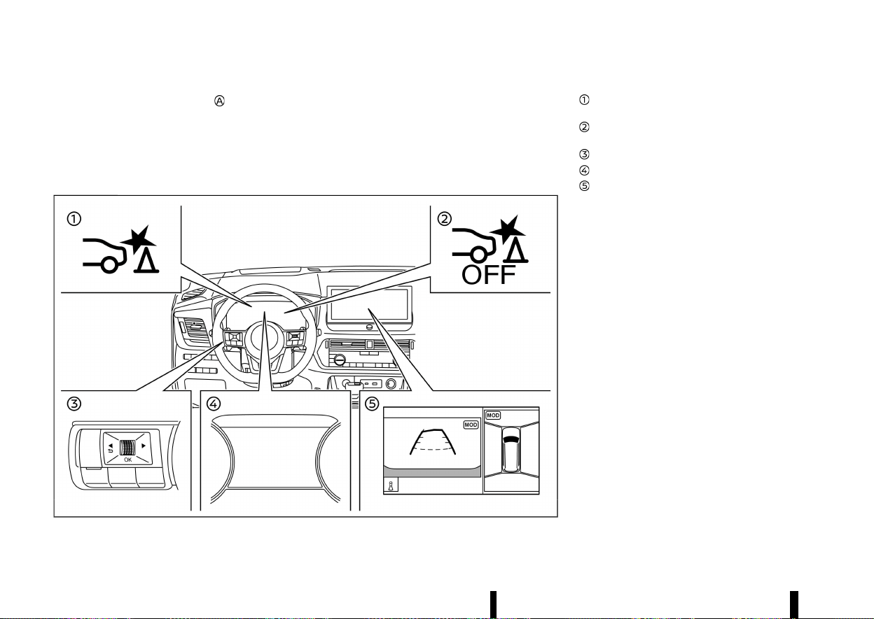
(382,1)
378 Starting and driving
vehicle using the parking sensors located on the
rear bumper.
NOTE:
You can temporarily cancel the sensor function
and the RAB system in the vehicle. For additional
information, see “Parking sensor (sonar) sys-
tem” (P.395).
MWAF1190X
Example
RAB system warning indicator (on the vehicle
information display)
RAB system OFF warning light (on the meter
panel)
Steering-wheel-mounted controls (left side)
Vehicle information display
Centre display (where fitted)
RAB SYSTEM OPERATION
MEVT33A1-E614DFD4-C945-4011-BE61-3A684EBB5084
When the shift lever is in the R (Reverse) position
and the vehicle speed is between approximately 3
km/h (2 MPH) and 15 km/h (9 MPH), the RAB system
operates.
If a risk of a collision with an obstacle is detected
when your vehicle is reversing, the RAB system
warning indicator will flash in the vehicle informa-
tion display, a red frame will appear in the centre
display (models with the Intelligent Around View
Monitor system), and the system will chime three
times. The system will then automatically apply the
brakes. After the automatic brake application, the
driver must depress the brake pedal to maintain
brake pressure.
NOTE:
* The brake lights of the vehicle come on
when braking is performed by the RAB
system.
* When the brakes operate, a noise may be
heard. This is not a malfunction.
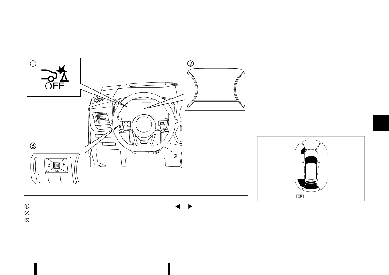
(383,1)
TURNING THE RAB SYSTEM ON/OFF
MEVT33A1-ABEF4B71-A6B6-4275-9D74-56C9FB7044AA
MWAF0436X
RAB system OFF warning light
Vehicle information display
Steering-wheel-mounted control (left side)
Perform the following steps to turn the RAB
system ON or OFF.
1. Push the
button until [Settings]
appears in the vehicle information display
and then push the scroll dial. Use the scroll
dial to select [Driver Assistance]. Then push the
scroll dial.
2. Select [Emergency Brake] and push the scroll
dial.
3. Select [Rear] and use the scroll dial to turn the
system on or off.
When the RAB system is turned off, the RAB system
OFF warning light illuminates when the shift lever
is in the "R" (Reverse) position.
The RAB system OFF warning light will also
illuminate when the shift lever is in the R (Reverse)
position and the RAB system is ON if the parking
sensors (sonar) have been temporarily disabled
using the [Parking Aids] setting.
NOTE:
* The RAB system will be automatically turned
on when the engine is restarted.
MWAF1166X
Example
* When the shift lever is in the "R" (Reverse)
position and the Parking Aids screen is
displayed in the vehicle information display,
the parking sensor (sonar) system can be
Starting and driving 379

(384,1)
380 Starting and driving
disabled temporarily by pushing the scroll
dial on the steering wheel.
RAB SYSTEM LIMITATIONS
MEVT33A1-254A760A-4C53-4BA7-A065-6C981DEAF20B
WARNING
Listed below are the system limitations for the
RAB system. Failure to follow the warnings and
instructions for proper use of the RAB system
could result in serious injury or death.
* When the vehicle approaches an obstacle
while the accelerator or brake pedal is
depressed, the function may not operate
or the start of the operation may be
delayed. The RAB system may not operate
or may not perform sufficiently due to
vehicle conditions, driving conditions, the
traffic environment, the weather, road sur-
face conditions, etc. Do not wait for the
system to operate. Operate the brake
pedal by yourself as soon as necessary.
* If it is necessary to override RAB operation,
strongly press the accelerator pedal.
* Always check your surroundings and turn
to check what is behind you before and
while reversing. The RAB system detects
stationary objects behind the vehicle. The
RAB system does not detect the following
objects:
— Moving objects
— Low objects
— Narrow objects
— Wedge-shaped objects
— Complex-shaped objects
— Multiple object in close
— Objects close to the bumper (less than
approximately 1 ft [30 cm])
— Objects that suddenly appear
— Thin objects such as rope, wire, chain,
etc.
* The RAB system may not operate for
pedestrians or animals.
* The RAB system may not operate for the
following obstacles:
— Obstacles located high off the ground
— Obstacles in a position offset from
your vehicle
— Obstacles, such as spongy materials or
snow, that have soft outer surfaces
and can easily absorb a sound wave
* The RAB system may not operate in the
following conditions:
— There is rain, snow, ice, dirt, etc.,
attached to the parking sensors.
— A loud sound is heard in the area
around the vehicle.
— The surface of the obstacle is diagonal
to the rear of the vehicle.
— The parking sensors or the area
around them are extremely hot or
cold.
* The RAB system may unintentionally oper-
ate in the following conditions:
— There is overgrown grass in the area
around the vehicle.
— There is a structure (e.g., a wall, toll
gate equipment, a narrow tunnel, a
parking lot gate) near the side of the
vehicle.
— There are bumps, protrusions, or man-
hole covers on the road surface.
— The vehicle is driving through a draped
flag or a curtain.
— The vehicle is driving on a steep hill.
— There is an accumulation of snow or
ice behind the vehicle.
— An ultrasonic wave source, such as
another vehicle’s parking sensor, is
near the vehicle.
* Once the automatic brake control oper-
ates, it does not operate again if the
vehicle approaches the same obstacle.
* The automatic brake control can only
operate for a short period of time. There-
fore, the driver must depress the brake
pedal.
* In the following situations, the RAB system
may not operate properly or may not
function sufficiently:
— The vehicle is driven in bad weather
(rain, fog, snow, etc.).
— The vehicle is driven on a steep hill.
— The vehicle’s posture is changed (e.g.,
when driving over a bump).
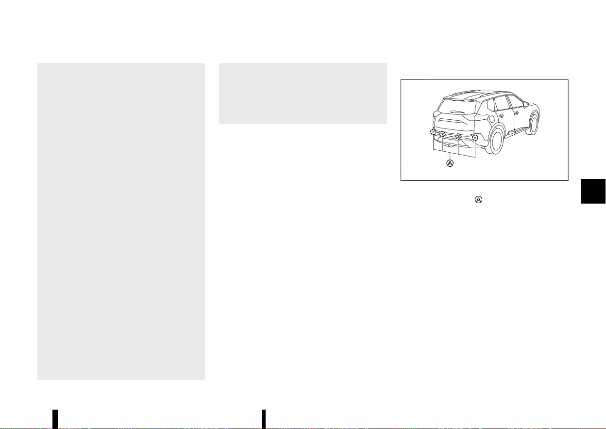
(385,1)
— The vehicle is driven on a slippery
road.
— The vehicle is turned sharply by turn-
ing the steering wheel fully.
— Snow chains are used.
— Wheels or tyres other than NISSAN
recommended are used.
— The brakes are cold at low ambient
temperatures or immediately after
driving has started.
— The braking force becomes poor due
to wet brakes after driving through a
puddle or washing the vehicle.
* Turn the RAB system off in the following
conditions to prevent the occurrence of an
unexpected accident resulting from sud-
den system operation:
— The vehicle is towed.
— The vehicle is carried on a flatbed
truck.
— The vehicle is on the chassis dynam-
ometer.
— The vehicle drives on an uneven road
surface.
— Suspension parts other than those
designated as genuine parts are used.
(If the vehicle height or the vehicle
body inclination is changed, the sys-
tem may not detect an obstacle cor-
rectly.)
* When towing a trailer or other vehicle, turn
the RAB system off to prevent the occur-
rence of an unexpected accident resulting
from sudden system operation. (See “RAB
system operation” (P.378).)
* Excessive noise (e.g., audio system volume,
an open vehicle window) will interfere with
the chime sound, and it may not be heard.
SYSTEM MALFUNCTION
MEVT33A1-809BBB5C-3EA3-446D-AB34-2BFBA1C6AFD0
If the RAB system malfunctions, it will be turned off
automatically, the RAB system OFF warning light
will illuminate, and the [System fault See Owner’s
Manual] warning message will appear in the
vehicle information display.
Action to take
MEVT33A1-B0BD1DEB-CF24-4E80-9BBA-4C4205FD9991
If the warning light illuminates, park the vehicle in a
safe location, turn the engine off, and restart the
engine. If the warning light continues to illuminate,
have the RAB system checked. It is recommended
that you visit a NISSAN dealer or qualified work-
shop for this service.
NOTE:
If the RAB system cannot be operated tempora-
rily, the RAB system OFF warning light blinks.
SYSTEM MAINTENANCE
MEVT33A1-BDC55E6C-3CBD-40ED-A047-DA168ABFA3A8
MWAF0647X
The parking sensors are located on the rear
bumper. Observe the following items to ensure
proper operation of the system:
* Always keep the sensors clean.
* If the sensors are dirty, wipe them off with a
soft cloth while being careful to not damage
them.
* The sensors may be blocked by temporary
ambient conditions such as splashing water,
mist or fog. The blocked condition may also be
caused by objects such as ice, frost or dirt
obstructing the sensors. Check for and re-
move objects obstructing the area around the
sensors.
* Do not subject the area around the sensors to
strong impact. Also, do not remove or disas-
semble the sensors. If the sensors and periph-
eral areas are deformed in an accident, etc.,
have the sensors checked. It is recommended
Starting and driving 381

(386,1)
382 Starting and driving
that you visit a NISSAN dealer or qualified
workshop for this service.
* Do not attach stickers (including transparent
material), install accessories or apply addi-
tional paint on the sensors and their surround-
ing areas. This may cause a malfunction or
improper operation.
* When washing the vehicle using a high-
pressure washer, do not apply direct washer
pressure on the sensors. This may cause a
malfunction of the sensors.
MEVT33A1-7C03A534-EF0E-40B7-84F0-13B8CB4EE473
Follow these easy-to-use Fuel Efficient Driving Tips
to help you achieve the most fuel economy from
your vehicle.
1. Use smooth accelerator and brake pedal
application.
.
Avoid rapid starts and stops.
.
Use smooth, gentle accelerator and brake
application whenever possible.
.
Maintain constant speed while commuting
and coast whenever possible.
2. Maintain constant speed.
.
Look ahead to try and anticipate and
minimise stops.
.
Synchronizing your speed with traffic lights
allows you to reduce your number of stops.
.
Maintaining a steady speed can minimise
red light stops and improve fuel efficiency.
3. Use air conditioning (A/C) at higher vehicle
speeds.
.
Below 64 km/h (40 MPH), it is more efficient
to open windows to cool the vehicle due to
reduced engine load.
.
Above 64 km/h (40 MPH), it is more efficient
to use A/C to cool the vehicle due to
increased aerodynamic drag.
.
Recirculating the cool air in the cabin when
the A/C is on reduces cooling load.
4. Drive at economical speeds and distances.
.
Observing the speed limit and not exceed-
ing 97 km/h (60 MPH) (where legally
allowed) can improve fuel efficiency due to
reduced aerodynamic drag.
.
Maintaining a safe following distance be-
hind other vehicles reduces unnecessary
braking.
.
Safely monitoring traffic to anticipate
changes in speed permits reduced braking
and smooth acceleration changes.
.
Select a gear range suitable to road condi-
tions.
5. Use cruise control.
.
Using cruise control during highway driving
helps maintain a steady speed.
.
Cruise control is particularly effective in
providing fuel savings when driving on flat
terrains.
6. Plan for the shortest route.
.
Utilise a map or navigation system (where
fitted) to determine the best route to save
time.
7. Avoid idling.
.
Shutting off your engine when safe for
stops exceeding 30-60 seconds saves fuel
and reduces emissions.
8. Buy an automated pass for toll roads.
.
Automated passes permit drivers to use
special lanes to maintain cruising speed
through the toll and avoid stopping and
starting.
9. Winter warm up.
.
Limit idling time to minimise impact to fuel
economy.
FUEL EFFICIENT DRIVING TIPS
FUEL EFFICIENT DRIVING TIPS

(387,1)
.
Vehicles typically need no more than 30
seconds of idling at start-up to effectively
circulate the engine oil before driving.
.
Your vehicle will reach its ideal operating
temperature more quickly while driving
versus idling.
10. Keeping your vehicle cool.
.
Park your vehicle in a covered parking area
or in the shade whenever possible.
.
When entering a hot vehicle, opening the
windows will help to reduce the inside
temperature faster, resulting in reduced
demand on your A/C system.
MEVT33A1-A7F7F37C-BB96-45E4-9A88-BFC0667354EF
* Keep your engine tuned up.
* Follow the recommended scheduled mainte-
nance.
* Keep the tyres inflated to the correct pressure.
Low tyre pressure increases tyre wear and
lowers fuel economy.
* Keep the wheels in correct alignment. Impro-
per alignment increases tyre wear and lowers
fuel economy.
* Use the recommended viscosity engine oil.
(See “Recommended fluids/lubricants and ca-
pacities” (P.456).)
MEVT33A1-81465BDD-5FC1-47C7-B978-1AA057225439
The Smart simple hybrid system helps to enhance
the fuel economy by controlling the Stop/Start
System, the torque assist function, and battery
charging by the electric motor (regeneration).
The vehicle has two batteries, a main battery (12-
volt) and an auxiliary battery (Lithium-ion), that is
specially designed for the Smart simple hybrid
system. (See “Battery” (P.437) for additional infor-
mation.)
CAUTION
Do not drive the vehicle with any of battery
terminal is disconnected. Doing so may lead to
the system malfunction and may cause an
accident.
NOTE:
* Use the special 12-volt battery (main bat-
tery) that is enhanced in regard to the
charge-discharge capacity and life perfor-
mance. Avoid using a non-special battery, as
this may cause early deterioration of the
battery or a malfunction of the Stop/Start
system and the torque assist function.
* For the 12-volt battery (main battery), it is
recommended to use Genuine NISSAN parts.
For more information, contact a NISSAN
dealer or qualified workshop.
* For the auxiliary battery (Lithium-ion), it is
recommended to use Genuine NISSAN parts.
For more information, contact a NISSAN
dealer or qualified workshop.
Starting and driving 383
INCREASING FUEL ECONOMY AND RE-
DUCING CARBON DIOXIDE EMISSIONS
INCREASING FUEL ECONOMY AND RE-
DUCING CARBON DIOXIDE EMISSIONS
SMART SIMPLE HYBRID SYSTEM
SMART SIMPLE HYBRID SYSTEM

(388,1)
384 Starting and driving
REGENERATION
MEVT33A1-D019FA96-A1DA-4F42-945D-1A552AC9264C
* When the vehicle is coasting (accelerator pedal
is released) or decelerating (brake pedal is
depressed) and the certain conditions are met,
the batteries can be charged by the electric
motor.
* Regenerated energy (electric power), stored in
the high-efficiency Lithium ion (Li-ion) battery
(auxiliary battery), is used for driving.
TORQUE ASSIST FUNCTION
MEVT33A1-8525C3E7-67D3-4630-9ED3-E1209C8AAB3E
* With the batteries sufficiently charged, when
restarting the vehicle from the Stop/Start
condition, the electric motor will assist the
acceleration torque for up to approximately 20
seconds.
* When the vehicle is accelerating, running the
electric motor (torque assist) will help to
reduce fuel consumption.
* The electric motor is run by regenerated
energy that was charged while decelerating.
NOTE:
The torque assist function will not activate
under the following conditions. (There may be
some situations other than those listed below
when the torque assist function will not acti-
vate.)
* Starting or accelerating abruptly.
* The brake pedal is depressed.
* The accelerator pedal is released.
* The Anti-lock Braking System (ABS) and/or
the Vehicle Dynamic Control (VDC)/Electro-
nic Stability Programme (ESP) system is in
operation.
* The batteries are not sufficiently charged.
* The outside temperature is low and the
battery function needs to be protected.
WARNING
Do not drive the vehicle with the battery
terminal disconnected. Each vehicle system
may cause malfunction resulting in an acci-
dent unexpectedly.
MEVT33A1-E736AF38-DC1B-4F99-A928-0D36F3CB2A37
WARNING
* Do not stop or park the vehicle over
flammable materials such as dry grass,
waste paper or rags. They may ignite and
cause a fire.
* Never leave the engine running while the
vehicle is unattended.
* When parking for an extended period of
time with Stop/Start System activated, the
engine will restart automatically. Never
leave the vehicle with the ignition switch
in the ON position.
* Do not leave children unattended inside
the vehicle. They could unknowingly acti-
vate switches or controls. Unattended
children could become involved in serious
accidents.
* To help avoid risk of injury or death
through unintended operation of the ve-
hicle and/or its systems, do not leave
children, people who require the assis-
tance of others or pets unattended in your
vehicle. Additionally, the temperature in-
side a closed vehicle on a warm day can
quickly become high enough to cause a
significant risk of injury or death to people
and pets.
* Safe parking procedures require that both
the parking brake be applied and the
transmission placed into P (Park). Failure
to do so could cause the vehicle to move
unexpectedly or roll away and result in an
accident.
PARKING
PARKING
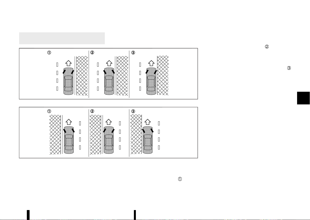
(389,1)
* Make sure the shift lever cannot be moved
without depressing the footbrake pedal.
MSSD0488
Left-Hand Drive (LHD) model
MSSD0489
Right-Hand Drive (RHD) model
1. Apply the parking brake.
2. Push the park button to shift to the P (Park)
position.
3. To help prevent the vehicle from rolling into
the street when parked on a sloping drive way,
it is a good practice to turn the wheels as
illustrated.
.
HEADED DOWNHILL WITH KERB:
Turn the wheels into the kerb and move the
vehicle forward until the kerb side wheel
gently touches the kerb.
.
HEADED UPHILL WITH KERB:
Turn the wheels away from the kerb and
move the vehicle back until the kerb side
wheel gently touches the kerb.
.
HEADED UPHILL OR DOWNHILL, NO KERB:
Turn the wheels toward the side of the road
so the vehicle will move away from the
centre of the road if it moves.
4. Place the ignition switch in the “OFF” position.
NOTE:
Use Stop/Start System when the vehicle is
stopped for a period of time, for example wait-
ing at stoplights. Stop the engine with the
ignition switch when parking, etc. for an ex-
tended period of time.
Starting and driving 385

(390,1)
386 Starting and driving
MEVT33A1-FEF1D02A-4FB7-4410-9B68-92088F358F69
Your new vehicle was designed to be used
primarily to carry passengers and luggage.
Towing a trailer will place additional loads on your
vehicle’s engine, drive train, steering, braking and
other systems. The towing of a trailer will exagge-
rate other conditions such as sway caused by
crosswinds, rough road surfaces or passing trucks.
Your driving style and speed must be adjusted
according to the circumstances. Before towing a
trailer, see a NISSAN dealer or qualified workshop
for an explanation about the proper use of towing
equipment.
OPERATING PRECAUTIONS
MEVT33A1-EE71CAB7-BDC7-4D35-A9E3-63CEE0ED51AA
* Avoid towing a trailer during the running-in
period.
* Before driving, make sure that the lighting
system of the trailer works properly.
* Observe the legal maximum speeds for trailer
operation.
Do not exceed 100 km/h (62 MPH) (for Europe).
* Avoid abrupt starts, accelerations and stops.
* Avoid sharp turns and lane changes.
* Always drive your vehicle at a moderate speed.
* Do not use the following systems (where
fitted) while towing a trailer:
— Lane Departure Warning (LDW) system
— Intelligent Lane Intervention system
— Emergency Lane Assist (ELA) system
— Blind Spot Warning (BSW) system
— Intelligent Blind Spot Intervention system
— Rear Cross Traffic Alert (RCTA) system
— Intelligent Cruise Control (ICC) system
— ProPILOT Assist system
— Intelligent Emergency Braking with Pedes-
trian Detection system
— Intelligent Forward Collision Warning sys-
tem
— Rear Automatic Braking (RAB) system
* Follow the trailer manufacturer’s instructions.
* Choose proper coupling devices (trailer hitch,
safety chain, roof carrier, etc.) for your vehicle
and trailer. These devices are available from a
NISSAN dealer or qualified workshop where
you can also obtain more detailed information
about trailer towing.
* Never allow the total trailer load (trailer weight
plus its cargo weight) to exceed the maximum
set for the vehicle and the coupling device. See
a NISSAN dealer or qualified workshop for
more information.
* The trailer must be loaded so that heavy
goods are placed over the axle. The maximum
allowable vertical load on the trailer hitch must
not be exceeded.
* Have your vehicle serviced more often than at
the intervals specified in a separate mainte-
nance booklet.
* Trailer towing requires more energy than
under normal circumstances because of a
considerable increase in traction power and
resistance.
TYRE PRESSURE
MEVT33A1-D69EC290-2CD3-4B3C-8D1C-8AA773558403
When towing a trailer, inflate the vehicle tyres to
the maximum recommended COLD tyre pressure
(for full loading) indicated on the tyre placard.
SAFETY CHAINS
MEVT33A1-24653995-85E8-4E6B-ABCC-79A2D0BBA8EB
Always use a suitable chain between the vehicle
and trailer. The chain should be crossed and
should be attached to the hitch, not to the vehicle
bumper or axle. Be sure to leave enough slack in
the chain to permit turning corners.
TRAILER BRAKES
MEVT33A1-D6D7E671-6E79-4031-90C0-14661F7E5198
Ensure that trailer brakes are installed as required
by local regulations. Also check that all other trailer
equipment conforms to local regulations.
Always block the wheels on both the vehicle and
trailer when parking. Apply the hand brake on the
trailer where fitted. Parking on a steep slope is not
recommended.
If parking on a steep slope is unavoidable, place
the shift lever in the P (Park) position, and turn the
front wheels towards the kerb.
TRAILER DETECTION (where fitted)
MEVT33A1-8158F223-B4C5-4D90-9512-6C5F427A674D
When towing a trailer with a genuine NISSAN tow
bar electrical kit and the turn signal switch is used,
the electrical system of the vehicle will detect the
additional electrical load of the trailer lighting. As a
result, the direction indicator tone will be different.
TRAILER TOWING
TRAILER TOWING

(391,1)
TRAILER SWAY CONTROL
MEVT33A1-281AF3D9-9BC9-4801-8A3E-108801664988
To minimise trailer sway, your vehicle may apply
braking to individual wheels based on input from
your vehicle sensors and vehicle speed. Trailer
Sway Control is a function of the Vehicle Dynamic
Control (VDC)/Electronic Stability Programme
(ESP) system and is active when the VDC/ESP
function is enabled.
CAUTION
If the VDC/ESP system is turned OFF, the
Trailer Sway Control is also disabled.
When Trailer Sway Control is in operation, the slip
indicator light blinks. When vehicle control is
regained, slip indicator light will turn OFF.
For additional information about the VDC/ESP
system, see “Vehicle Dynamic Control (VDC)/Elec-
tronic Stability Programme (ESP) system” (P.391).
If Trailer Sway Control activates
MEVT33A1-73C803DD-C2CC-4B01-A81F-0325EEAA8806
1. Take your foot off the accelerator pedal to
allow the vehicle to coast and steer as straight
ahead as the road conditions allow. This
combination will help stabilise the vehicle.
CAUTION
Do not try to correct trailer sway by
steering or applying the brakes.
2. When the trailer sway stops, gently apply the
brakes and pull to the side of the road in a safe
area.
3. Try to rearrange the trailer load so it is
balanced.
NOTE:
Trailer Sway Control cannot reduce trailer sway
in all situations.
Starting and driving 387
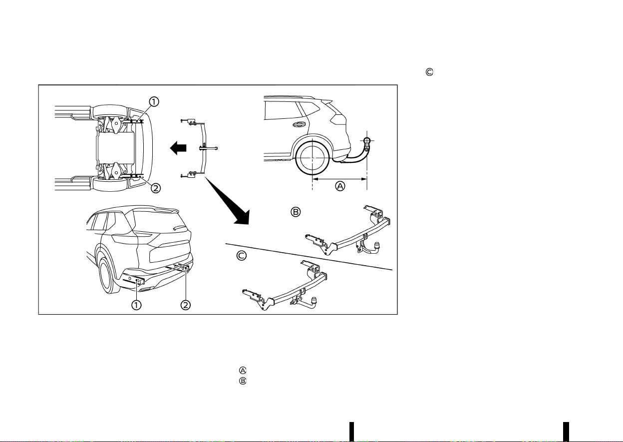
(392,1)
388 Starting and driving
COUPLING DEVICE INSTALLATION (for Europe)
MEVT33A1-F83F1A72-2B12-4D77-91D5-9CEE857AFA8E
MWAF1191X
NISSAN recommends that the coupling device for
trailer towing be installed under the following
conditions:
* Maximum permissible vertical load on the
coupling device: 981 N (100 kg, 221 lb)
* The coupling device, mounting points and
installation parts on your vehicle: as shown
as an example in the illustration.
* Rear overhang of coupling device:
1,120 mm (44.1 in)
Fixed tow bar
Detachable tow bar
Follow all of the coupling device manufacturer’s
instructions for installation and use.
(393,1)
MEVT33A1-FCEF4119-86A5-4E02-81F1-220A1BD67BD0
WARNING
* If the engine is not running or is turned off
while driving, the power assist for the
steering will not work. Steering will be
harder to operate.
* When the electric power steering warning
light illuminates with the engine running,
the power assist for the steering will cease
operation. You will still have control of the
vehicle but the steering will be harder to
operate.
The electric power steering is designed to provide
power assist while driving to operate the steering
wheel with light force.
When SPORT mode is selected, the steering wheel
effort is moderately increased for a sporty feel.
(See “SPORT mode” (P.249).)
When the steering wheel is operated repeatedly or
continuously while parking or driving at a very low
speed, the power assist for the steering wheel will
be reduced. This is to prevent overheating of the
electric power steering and protect it from getting
damaged. While the power assist is reduced,
steering wheel operation will become heavy. If
the steering wheel operation is still performed, the
electric power steering may stop and the electric
power steering warning light
will illuminate. In
a safe location, stop the engine and place the
ignition switch in the “OFF” position. When the
temperature of the electric power steering goes
down, the power assist level will return to normal.
Avoid repeating such steering wheel operations
that could cause the electric power steering to
overheat.
You may hear a noise when the steering wheel is
operated quickly. However, this is not a malfunc-
tion.
If the electric power steering warning light illumi-
nates while the engine is running, it may indicate
the electric power steering is not functioning
properly and may need servicing. Have the electric
power steering checked. It is recommended that
you visit a NISSAN dealer or qualified workshop for
this service. (See “Electric power steering warning
light” (P.76).)
When the electric power steering warning light
illuminates with the engine running, the power
assist for the steering will cease operation. You will
still have control of the vehicle. However, greater
steering effort is needed, especially in sharp turns
and at low speeds.
MEVT33A1-C85EA487-970D-4143-8E32-0A76E249C62B
BRAKING PRECAUTIONS
MEVT33A1-E193E720-D853-4379-82DC-E8EA84DDFD5B
The brake system has two separate hydraulic
circuits. If one circuit malfunctions, you will still
have braking at two wheels.
Vacuum assisted brakes
MEVT33A1-0E23F656-D41A-488F-8147-9851A53DE80D
The brake booster aids braking by using engine
vacuum. If the engine stops, you can stop the
vehicle by depressing the brake pedal. However,
greater foot pressure on the brake pedal will be
required to stop the vehicle and the stopping
distance will be longer.
Using the brakes
MEVT33A1-68FFF67F-04F0-402E-BB4B-882B90506CCB
Avoid resting your foot on the brake pedal while
driving. This will cause overheating of the brakes,
wearing out the brake pads faster and reduce gas
mileage.
To help reduce brake wear and to prevent the
brakes from overheating, reduce speed and down-
shift to a lower gear before going down a slope or
long grade. Overheated brakes may reduce brak-
ing performance and could result in loss of vehicle
control.
WARNING
* While driving on a slippery surface, be
careful when braking, accelerating or
downshifting. Abrupt braking or accelerat-
ing could cause the wheels to skid and
result in an accident.
* If the engine is not running or is turned off
while driving, the power assist for the
Starting and driving 389
ELECTRIC POWER STEERING
ELECTRIC POWER STEERING
BRAKE SYSTEM
BRAKE SYSTEM

(394,1)
390 Starting and driving
brakes will not work. Braking will be hard-
er.
Wet brakes
MEVT33A1-853A77D3-7334-4546-A056-4F62470691EB
When the vehicle is washed or driven through
water, the brakes may get wet. As a result, your
braking distance will be longer and the vehicle may
pull to one side during braking.
To dry brakes, drive the vehicle at a safe speed
while lightly tapping the brake pedal to heat-up
the brakes. Do this until the brakes return to
normal. Avoid driving the vehicle at high speeds
until the brakes function correctly.
Parking brake running-in
MEVT33A1-3CACC1C2-C000-436E-B53F-77E9E90BA938
Break in the parking brake pads whenever the
stopping effect of the parking brake is weakened
or whenever the parking brake pads and/or
callipers/rotors are replaced, in order to assure
the best braking performance.
This procedure is described in the vehicle service
manual. It is recommended you visit a NISSAN
dealer or qualified workshop for this service.
BRAKE ASSIST
MEVT33A1-4F7C10AE-4D30-42D8-A185-FF61F97693EE
When the force applied to the brake pedal exceeds
a certain level, the Brake Assist is activated
generating greater braking force than a conven-
tional brake booster even with light pedal force.
WARNING
The Brake Assist is only an aid to assist braking
operation and is not a collision warning or
avoidance device. It is the driver’s responsi-
bility to stay alert, drive safely and be in control
of the vehicle at all times.
ANTI-LOCK BRAKING SYSTEM (ABS)
MEVT33A1-AD934732-3AE5-459A-B8C3-7A014C0C24D9
WARNING
* The Anti-lock Braking System (ABS) is a
sophisticated device, but it cannot prevent
accidents resulting from careless or dan-
gerous driving techniques. It can help
maintain vehicle control during braking
on slippery surfaces. Remember that stop-
ping distances on slippery surfaces will be
longer than on normal surfaces even with
ABS. Stopping distances may also be long-
er on rough, gravel or snow covered roads,
or if you are using tyre chains. Always
maintain a safe distance from the vehicle
in front of you. Ultimately, the driver is
responsible for safety.
* Tyre type and condition may also affect
braking effectiveness.
— When replacing tyres, install the spe-
cified size of tyres on all four wheels.
— For detailed information, see “Tyres
and Wheels” (P.448).
The Anti-lock Braking System (ABS) controls the
brakes so the wheels do not lock during hard
braking or when braking on slippery surfaces. The
system detects the rotation speed at each wheel
and varies the brake fluid pressure to prevent each
wheel from locking and sliding. By preventing each
wheel from locking, the system helps the driver
maintain steering control and helps to minimise
swerving and spinning on slippery surfaces.
Using the system
MEVT33A1-597530BD-6BA0-4B9D-B015-6FBB8D66C7EE
Depress the brake pedal and hold it down. Depress
the brake pedal with firm steady pressure, but do
not pump the brakes. The ABS will operate to
prevent the wheels from locking up. Steer the
vehicle to avoid obstacles.
WARNING
Do not pump the brake pedal. Doing so may
result in increased stopping distances.
Self-test feature
MEVT33A1-A2B20D88-3F8D-458B-A01C-ABFC4E8BBA39
The ABS includes electronic sensors, electric
pumps, hydraulic solenoids and a computer. The
computer has a built-in diagnostic feature that
tests the system each time you start the engine
and move the vehicle at a low speed in forward or
reverse. When the self-test occurs, you may hear a
“clunk” noise and/or feel a pulsation in the brake
pedal. This is normal and does not indicate a
malfunction. If the computer senses a malfunction,
it switches the ABS off and illuminates the ABS
warning light on the instrument panel. The brake
system then operates normally, but without anti-
lock assistance.
If the ABS warning light illuminates during the self-
test or while driving, have the vehicle checked. It is
recommended you visit a NISSAN dealer or quali-
fied workshop for this service.

(395,1)
Normal operation
MEVT33A1-9CBA1EE9-2858-46A7-AF1C-F9A91252FE68
The ABS operates at speeds above 5 to 10 km/h (3
to 6 MPH). The speed varies according to road
conditions.
When the ABS senses that one or more wheels are
close to locking up, the actuator rapidly applies
and releases hydraulic pressure. This action is
similar to pumping the brakes very quickly. You
may feel a pulsation in the brake pedal and hear a
noise from under the bonnet or feel a vibration
from the actuator when it is operating. This is
normal and indicates that the ABS is operating
properly. However, the pulsation may indicate that
road conditions are hazardous and extra care is
required while driving.
MEVT33A1-860FE458-6080-435C-ADFF-7F016BF62430
Except for Europe: Vehicle Dynamic Control
(VDC) system
For Europe: Electronic Stability Programme
(ESP) system
The Vehicle Dynamic Control (VDC)/Electronic
Stability Programme (ESP) system uses various
sensors to monitor driver inputs and vehicle
motion. Under certain driving conditions, the
VDC/ESP system helps to perform the following
functions.
* Controls brake pressure to reduce wheel slip
on one slipping drive wheel so power is
transferred to a non slipping drive wheel on
the same axle.
* Controls brake pressure and engine output to
reduce drive wheel slip based on vehicle speed
(traction control function).
* Controls brake pressure at individual wheels
and engine output to help the driver maintain
control of the vehicle in the following condi-
tions:
— understeer (vehicle tends to not follow the
steered path despite increased steering
input)
— oversteer (vehicle tends to spin due to
certain road or driving conditions).
The VDC/ESP system can help the driver to
maintain control of the vehicle, but it cannot
prevent loss of vehicle control in all driving
situations.
When the VDC/ESP system operates, the slip
indicator light
in the instrument panel flashes
so note the following:
* The road may be slippery or the system may
determine some action is required to help
keep the vehicle on the steered path.
* You may feel a pulsation in the brake pedal
and hear a noise or vibration from under the
bonnet. This is normal and indicates that the
VDC/ESP system is working properly.
* Adjust your speed and driving to the road
conditions.
If a malfunction occurs in the system, the slip
indicator light
illuminates in the instrument
panel. The VDC/ESP system automatically turns
off.
The vehicle information display is used to turn off
the VDC/ESP system. The VDC/ESP off indicator
illuminates to indicate the VDC/ESP system is
off. When the VDC/ESP system is turned off, the
VDC/ESP system still operates to prevent one drive
wheel from slipping by transferring power to a non
slipping drive wheel. The slip indicator light
flashes if this occurs. All other VDC/ESP functions
are off, and the slip indicator light
will not
flash. The VDC/ESP system is automatically reset
to on when the ignition switch is placed in the off
position then back to the on position.
See “Slip indicator light” (P.80) and “Vehicle Dy-
namic Control (VDC) off indicator light (except for
Europe)/Electronic Stability Programme (ESP) off
indicator light (for Europe)” (P.80).
The computer has a built-in diagnostic feature
that tests the system each time you start the
engine and move the vehicle forward or in reverse
at a slow speed. When the self-test occurs, you
may hear a “clunk” noise and/or feel a pulsation in
Starting and driving 391
VEHICLE DYNAMIC CONTROL
(VDC)/ELECTRONIC STABILITY
PROGRAMME (ESP) SYSTEM
VEHICLE DYNAMIC CONTROL
(VDC)/ELECTRONIC STABILITY
PROGRAMME (ESP) SYSTEM
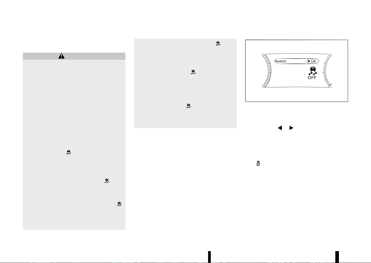
(396,1)
392 Starting and driving
the brake pedal. This is normal and is not an
indication of a malfunction.
WARNING
* The VDC/ESP system is designed to help
improve driving stability but does not
prevent accidents due to abrupt steering
operation at high speeds or by careless or
dangerous driving techniques. Reduce ve-
hicle speed and be especially careful when
driving and cornering on slippery surfaces
and always drive carefully.
* Do not modify the vehicle’s suspension. If
suspension parts such as shock absorbers,
struts, springs, stabiliser bars, bushings
and wheels are not NISSAN recommended
for your vehicle or are extremely deterio-
rated, the VDC/ESP system may not oper-
ate properly. This could adversely affect
vehicle handling performance, and the slip
indicator light
may illuminate.
* If brake related parts such as brake pads,
rotors and callipers are not NISSAN recom-
mended or are extremely deteriorated, the
VDC/ESP system may not operate properly
and the slip indicator light
may
illuminate.
* If engine control related parts are not
NISSAN recommended or are extremely
deteriorated, the slip indicator light
may illuminate.
* When driving on extremely inclined sur-
faces such as higher banked corners, the
VDC/ESP system may not operate properly
and the slip indicator light
may
illuminate. Do not drive on these types of
roads.
* When driving on an unstable surface such
as a turntable, ferry, elevator or ramp, the
slip indicator light
may illuminate.
This is not a malfunction. Restart the
engine after driving onto a stable surface.
* If wheels or tyres other than the NISSAN
recommended ones are used, the VDC/ESP
system may not operate properly and the
slip indicator light
may illuminate.
* The VDC/ESP system is not a substitute for
winter tyres or tyre chains on a snow
covered road.
HOW TO TURN OFF THE VDC/ESP
SYSTEM
MEVT33A1-CA4CB537-526B-4212-B68C-EEDD4B78F02A
The vehicle should be driven with the Vehicle
Dynamic Control (VDC)/Electronic Stability Pro-
gramme (ESP) system ON for most driving condi-
tions.
When the vehicle is stuck in mud or snow, the VDC/
ESP system reduces the engine output to reduce
wheel spin. The engine speed will be reduced even
if the accelerator is depressed to the floor. If
maximum engine power is needed to free a stuck
vehicle, turn the VDC/ESP system off.
MWAF0521X
Example
To turn off the VDC/ESP system, perform the
following steps in the vehicle information display.
1. Push the
button on the steering
wheel until [Settings] appears and then push
the job dial.
2. Use the scroll dial to select [VDC Setting]/[ESP
Setting] and then push it.
3. Select [System] and push the scroll dial. The
indicator light will illuminate.
Turn [VDC Setting]/[ESP Setting] back on in the
vehicle information display or restart the engine to
turn on the VDC/ESP system.
BRAKE FORCE DISTRIBUTION
MEVT33A1-DBCE7A81-6654-4F90-BC21-4931E718C6E6
During braking while driving through turns, the
system optimizes the distribution of force to each
of the four wheels depending on the radius of the
turn.
(397,1)
WARNING
* The VDC/ESP system is designed to help
the driver maintain stability but does not
prevent accidents due to abrupt steering
operation at high speeds or by careless or
dangerous driving techniques. Reduce ve-
hicle speed and be especially careful when
driving and cornering on slippery surfaces
and always drive carefully.
* Do not modify the vehicle’s suspension. If
suspension parts such as shock absorbers,
struts, springs, stabiliser bars, bushings
and wheels are not NISSAN recommended
for your vehicle or are extremely deterio-
rated, the VDC/ESP system may not oper-
ate properly. This could adversely affect
vehicle handling performance, and the
indicator light may flash or both the
and indicator lights may illumi-
nate.
* If brake related parts such as brake pads,
rotors and callipers are not NISSAN recom-
mended or are extremely deteriorated, the
VDC/ESP system may not operate properly
and both the
and indicator lights
may illuminate.
* If engine control related parts are not
NISSAN recommended or are extremely
deteriorated, both the
and in-
dicator lights may illuminate.
* When driving on extremely inclined sur-
faces such as higher banked corners, the
VDC/ESP system may not operate properly
and the
indicator light may flash or
both the
and indicator lights may
illuminate. Do not drive on these types of
roads.
* When driving on an unstable surface such
as a turntable, ferry, elevator or ramp, the
indicator light may flash or both the
and indicator lights may illumi-
nate. This is not a malfunction. Restart the
engine after driving onto a stable surface.
* If wheels or tyres other than the NISSAN
recommended ones are used, the VDC/ESP
system may not operate properly and the
indicator light may flash or both the
and indicator lights may illumi-
nate.
* The VDC/ESP system is not a substitute for
winter tyres or tyre chains on a snow
covered road.
MEVT33A1-751DFC83-9657-4E14-9890-5EA39413B84F
The chassis control is an electric control module
that includes the following functions:
* Intelligent Trace Control
* Intelligent Ride Control
INTELLIGENT TRACE CONTROL
MEVT33A1-9EA7EC27-8882-4CD9-A3A6-AFBE8477F7F7
This system senses driving based on the driver’s
steering and acceleration/braking patterns, and
controls brake pressure at individual wheels to aid
tracing at corners and help smooth vehicle re-
sponse.
When the VDC/ESP system is turned off, the
Intelligent Trace Control is also turned off. Amount
of brake control is changed depending on the
mode selected by the Drive Mode Selector.
When the Intelligent Trace Control is not function-
ing properly, the master warning light illuminates,
and the warning message [Chassis control system
fault] will also appear in the vehicle information
display.
If the chassis control warning message appears in
the vehicle information display, it may indicate that
the Intelligent Trace Control is not functioning
properly. Have the system checked as soon as
possible. It is recommended that you visit a NISSAN
dealer or qualified workshop for this service. (See
“Vehicle information display warnings and indica-
tors” (P.91).)
WARNING
The Intelligent Trace Control may not be
effective depending on the driving condition.
Always drive carefully and attentively.
Starting and driving 393
CHASSIS CONTROL
CHASSIS CONTROL

(398,1)
394 Starting and driving
When the Intelligent Trace Control is operating,
you may feel a pulsation in the brake pedal, sense
slight deceleration, or hear a noise. This is normal
and indicates that the Intelligent Trace Control is
operating properly. You may also feel deceleration
when the Intelligent Trace Control is operating.
However, this is not a malfunction.
INTELLIGENT RIDE CONTROL
MEVT33A1-3DF77A8B-4611-40F5-ACFB-9E761902C94C
This system senses upper body motion and
controls four wheel brake pressure. This will
enhance ride comfort in an effort to restrain
uncomfortable upper body movement when pas-
sing over undulated road surfaces. When the VDC/
ESP system is turned off, the Intelligent Ride
Control is also turned off.
If the chassis control warning message appears in
the vehicle information display, it may indicate that
the Intelligent Ride Control is not functioning
properly. Have the system checked as soon as
possible. It is recommended that you visit a NISSAN
dealer or qualified workshop for this service.
WARNING
The Intelligent Ride Control may not be effec-
tive depending on driving condition. Always
drive carefully and attentively.
When the Intelligent Ride Control is operating, you
may feel a pulsation in the brake pedal, sense
slight deceleration, or hear a noise. This is normal
and indicates that the Intelligent Ride Control is
operating properly. You may also feel deceleration
when the Intelligent Ride Control is operating.
However, this is not a malfunction.
MEVT33A1-3B8894E5-12A8-4EF1-835B-916E9DCE3071
WARNING
* Never rely solely on the hill start assist
system to prevent the vehicle from moving
backward on a hill. Always drive carefully
and attentively. Depress the brake pedal
when the vehicle is stopped on a steep hill.
Be especially careful when stopped on a
hill on frozen or muddy roads. Failure to
prevent the vehicle from rolling backwards
may result in a loss of control of the vehicle
and possible serious injury or death.
* The hill start assist system is not designed
to hold the vehicle at a standstill on a hill.
Depress the brake pedal when the vehicle
is stopped on a steep hill. Failure to do so
may cause the vehicle to roll backwards
and may result in a collision or serious
personal injury.
* The hill start assist system may not pre-
vent the vehicle from rolling backwards on
a hill under all load or road conditions.
Always be prepared to depress the brake
pedal to prevent the vehicle from rolling
backwards. Failure to do so may result in a
collision or serious personal injury.
The hill start assist system automatically keeps the
brakes applied to help prevent the vehicle from
rolling backwards in the time it takes the driver to
release the brake pedal and apply the accelerator
when the vehicle is stopped on a hill.
The hill start assist system will operate automati-
cally under the following conditions:
* The transmission is shifted to a forward or
reverse gear.
* The vehicle is stopped completely on a hill by
applying the brake.
The maximum holding time is 2 seconds. After 2
seconds the vehicle will begin to roll back and the
hill start assist system will stop operating com-
pletely.
The hill start assist system will not operate when
the transmission is shifted to the N (Neutral) or P
(Park) position or on a flat and level road.
When the slip indicator light illuminates in the
meter, the hill start assist system will not operate.
(See “Slip indicator light” (P.80).)
HILL START ASSIST SYSTEM
HILL START ASSIST SYSTEM
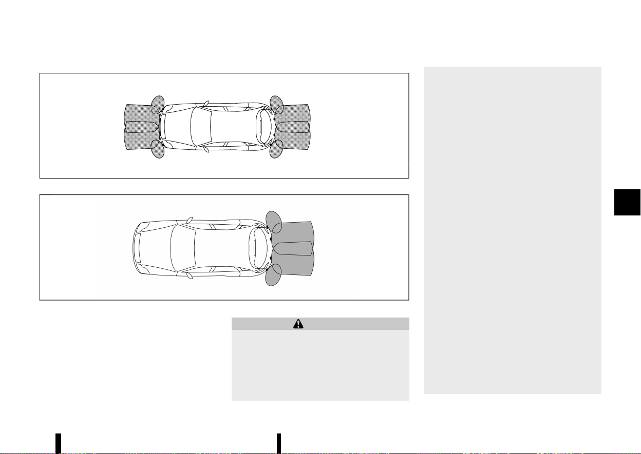
(399,1)
MEVT33A1-DD76DA45-7226-4443-A6F9-A878B9EBCE79
MSSD0622
Type A
MWAF1088X
Type B
The parking sensor (sonar) system sounds a tone
to inform the driver of obstacles near the bumper.
When the parking sensor (sonar) system is turned
on, the parking sensor (sonar) view will automati-
cally appear in the vehicle information display.
WARNING
* The parking sensor (sonar) system is a
convenience but it is not a substitute for
proper parking.
* The driver is always responsible for safety
during parking and other manoeuvres.
Always look around and check that it is
safe to do so before parking.
* If there is any doubt the surroundings in
the path of the parking area and/or the
parking area itself are not free from
obstacles, immediately stop the vehicle
and check the surroundings.
* Read and understand the limitations of the
parking sensor (sonar) system as con-
tained in this section. The colours of the
parking sensor indicator and the distance
guide lines in the front (where fitted)/rear
view indicate different distances to the
object.
* Inclement weather or ultrasonic sources
such as an automatic car wash, a truck’s
compressed-air brakes or a pneumatic drill
may affect the function of the system; this
may include reduced performance or a
false activation.
* The parking sensor (sonar) system is de-
signed as an aid to the driver in detecting
large stationary objects to help avoid
damaging the vehicle.
* The parking sensor (sonar) system is not
designed to prevent contact with small or
moving objects. Always move slowly. The
system will not detect small objects below
the bumper, and may not detect objects
close to the bumper or on the ground.
* The parking sensor (sonar) system may
not detect the following objects: fluffy
objects such as snow, cloth, cotton, glass-
wool, etc.; thin objects such as rope, wire
and chain, etc.; or wedge-shaped objects.
Starting and driving 395
PARKING SENSOR (sonar) SYSTEM
PARKING SENSOR (sonar) SYSTEM
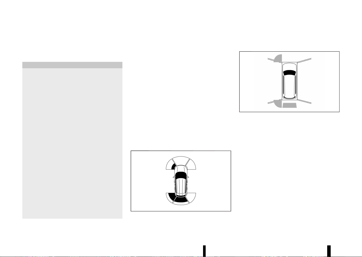
(400,1)
396 Starting and driving
If your vehicle sustains damage to the bumper
fascia, leaving it misaligned or bent, the sensing
zone may be altered causing inaccurate measure-
ment of obstacles or false alarms.
CAUTION
* Excessive noise (such as audio system
volume or an open vehicle window) will
interfere with the tone and it may not be
heard.
* The front (where fitted) and rear parking
sensors (sonar) detect the distance be-
tween the vehicle and the obstacle by
detecting the sound wave reflected from
the surface of the obstacle. When there is a
sound such as horn, or an ultrasonic
source (such as sonar of other vehicles)
around the vehicle, the sensor (sonar) may
not detect objects properly.
* In some conditions (for example, after a
car wash or a rain) water can accumulate
around the parking sensors (sonar), and
this may reduce performance of the sys-
tem or cause a false activation. This water
will drain away automatically while driving,
bringing the system performance back to
normal.
* Keep the parking sensors (located on the
bumper fascia) free from snow, ice and
large accumulations of dirt. Do not clean
the sonar with sharp objects. If the sensors
are covered, the accuracy of the parking
sensor (sonar) function will be diminished.
SYSTEM OPERATION
MEVT33A1-713D648A-4F26-4D0B-95E9-384520DF4D64
The system informs with a visual and audible alert
of:
* front obstacles when the shift lever is in the
"D" (Drive) position (where fitted)
* front (where fitted) and rear obstacles when
the shift lever is in the "R" (Reverse) position.
The system is deactivated at speeds above 10
km/h (6 MPH). It is reactivated at lower speeds.
The tone will stop when the obstacle get away
from the vehicle.
When the object is detected, the indicator (green)
appears and blinks and the tone sounds intermit-
tently. When the vehicle moves closer to the object,
the colour of the indicator turns yellow and the
rate of the blinking increases. When the vehicle is
very close to the object, the indicator stops
blinking and turns red, and the tone sounds
continuously.
MWAF0833X
Example
When the vehicle moves closer to an obstacle, the
parking sensor indicator (detected area) appears
in the vehicle information display.
MWAF0834X
Example
The parking sensor indicator also appears on the
camera view of the centre display (where fitted).
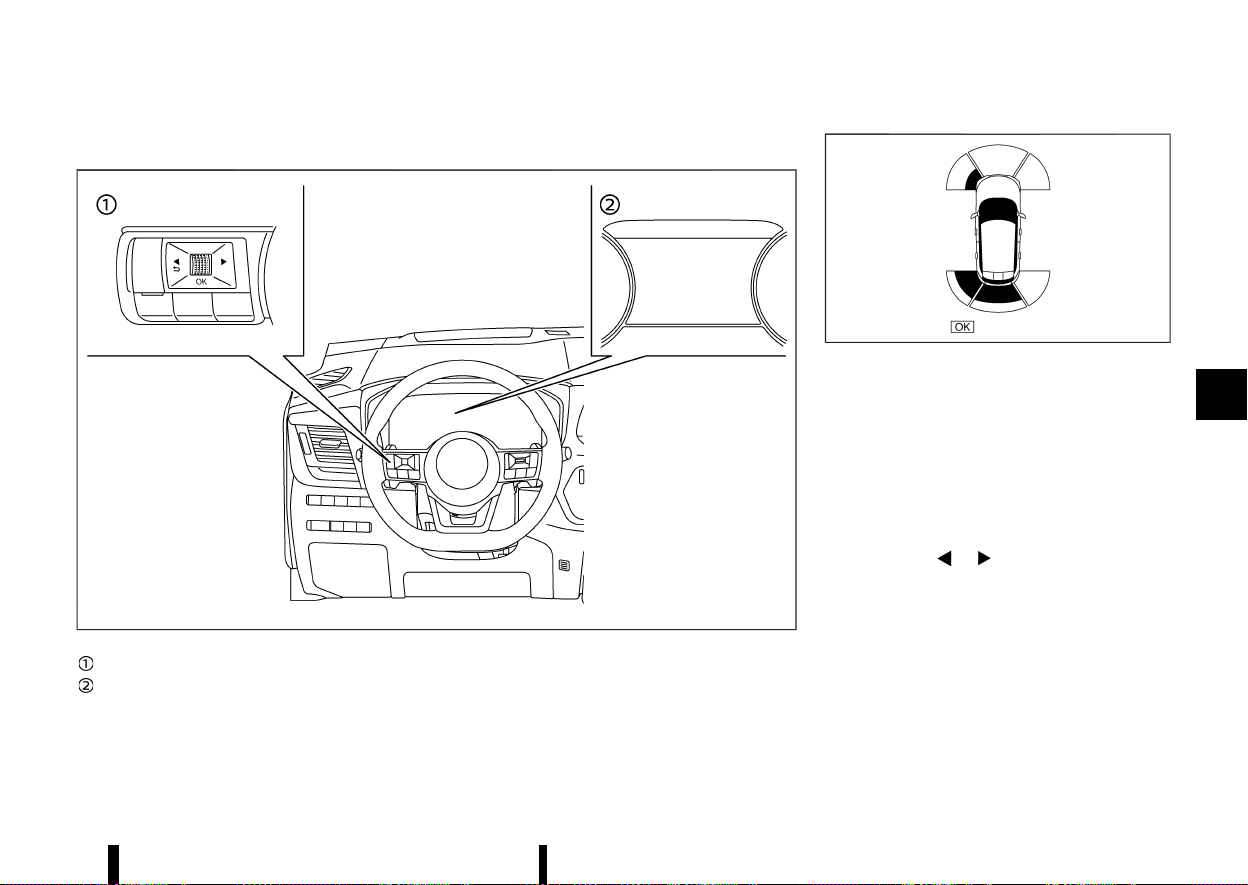
(401,1)
TURNING ON AND OFF THE PARKING SENSOR (sonar) FUNCTION
MEVT33A1-65DDA412-58D0-4E47-9467-8869A1CCBA36
MWAF0412X
Steering-wheel-mounted control (left side)
Vehicle information display
The system is automatically activated when the
ignition switch is in the ON position and the shift
lever is in the D (Drive) (models with front sensors)
or R (Reverse) position.
MWAF1166X
Example
NOTE:
When the shift lever is in the R (Reverse) position
and the Parking Aids screen is displayed in the
vehicle information display, the parking sensor
(sonar) system can be disabled temporarily by
pushing the scroll dial on the steering wheel.
Perform the following steps to set up the parking
sensor (sonar) system function.
1. Push the
button until [Settings]
appears in the vehicle information display
and then push the scroll dial. Use the scroll
dial to select [Driver Assistance]. Then push the
scroll dial.
2. Select [Parking Aids] and push the scroll dial.
3. Use the scroll dial to navigate in the menu and
select or change an item:
.
[Moving Object] (where fitted)
— Turns ON/OFF the Moving Object Detec-
Starting and driving 397

(402,1)
398 Starting and driving
tion (MOD) (See “Moving Object Detection
(MOD) (where fitted)” (P.200).)
.
[Display]
— Shows the parking sensor display in the
vehicle information display when the park-
ing sensor (sonar) system activates
.
[Front] (where fitted)
— Turns ON/OFF the front sensors
.
[Rear]
— Turns ON/OFF the rear sensors
.
[Distance]
— Changes the sensor’s detection distance
to [Far], [Medium] or [Near]
.
[Volume]
— Changes the volume of the tone sound to
[High], [Medium] or [Low]
PARKING SENSOR (sonar) SYSTEM LIM-
ITATIONS
MEVT33A1-68E70BBB-F371-4458-8A43-4E617AA49AA3
WARNING
Listed below are the system limitations for the
parking sensor (sonar) system. Failure to
operate the vehicle in accordance with these
system limitations could result in serious injury
or death.
* Read and understand the limitations of the
parking sensor (sonar) system as con-
tained in this section. Inclement weather
may affect the function of the sonar
system; this may include reduced perfor-
mance or a false activation.
* The parking sensor (sonar) system is
deactivated at speeds above 10 km/h (6
MPH). It is reactivated at lower speeds.
* Inclement weather or ultrasonic sources
such as an automatic car wash, a truck’s
compressed-air brakes or a pneumatic drill
may affect the function of the parking
sensor (sonar) system; this may include
reduced performance or a false activation.
* The parking sensor (sonar) system is not
designed to prevent contact with small or
moving objects. Always move slowly. The
system will not detect small objects below
the bumper or on the ground.
* The parking sensor (sonar) system may
not detect the following objects: fluffy
objects such as snow, cloth, cotton, glass-
wool, etc.; thin objects such as rope, wire
and chain, etc.; or wedge-shaped objects;
complex-shaped objects or multiple ob-
jects in close.
* The parking sensor (sonar) system may
not detect objects at speed above 5 km/h
(3 MPH) and may not detect certain angu-
lar or moving objects.
* The parking sensor (sonar) system may
not detect the following objects:
— Pedestrians who approach the vehicle
from the side
— Objects placed next to the vehicle
* The parking sensor (sonar) system may
not operate in the following conditions:
— When rain, snow, ice, dirt, etc. adheres
to the parking sensor.
— When a loud sound is heard in the area
around the vehicle.
— When the surface of the obstacle is
diagonal to the front or rear of the
vehicle.
— When a parking sensor or the area
around the sensor is extremely hot or
cold.
* The parking sensor (sonar) system may
unintentionally operate in the following
conditions:
— When there is overgrown grass in the
area around the vehicle.
— When there is a structure (for example,
a wall, a toll gate equipment, a narrow
tunnel or a parking lot gate) near the
side of the vehicle.
— When there are bumps, protrusions or
manhole covers on the road surface.
— When the vehicle drives through a
draped flag or a curtain.
— When there is an accumulation of
snow or ice behind the vehicle.
— When driving on a steep hill.
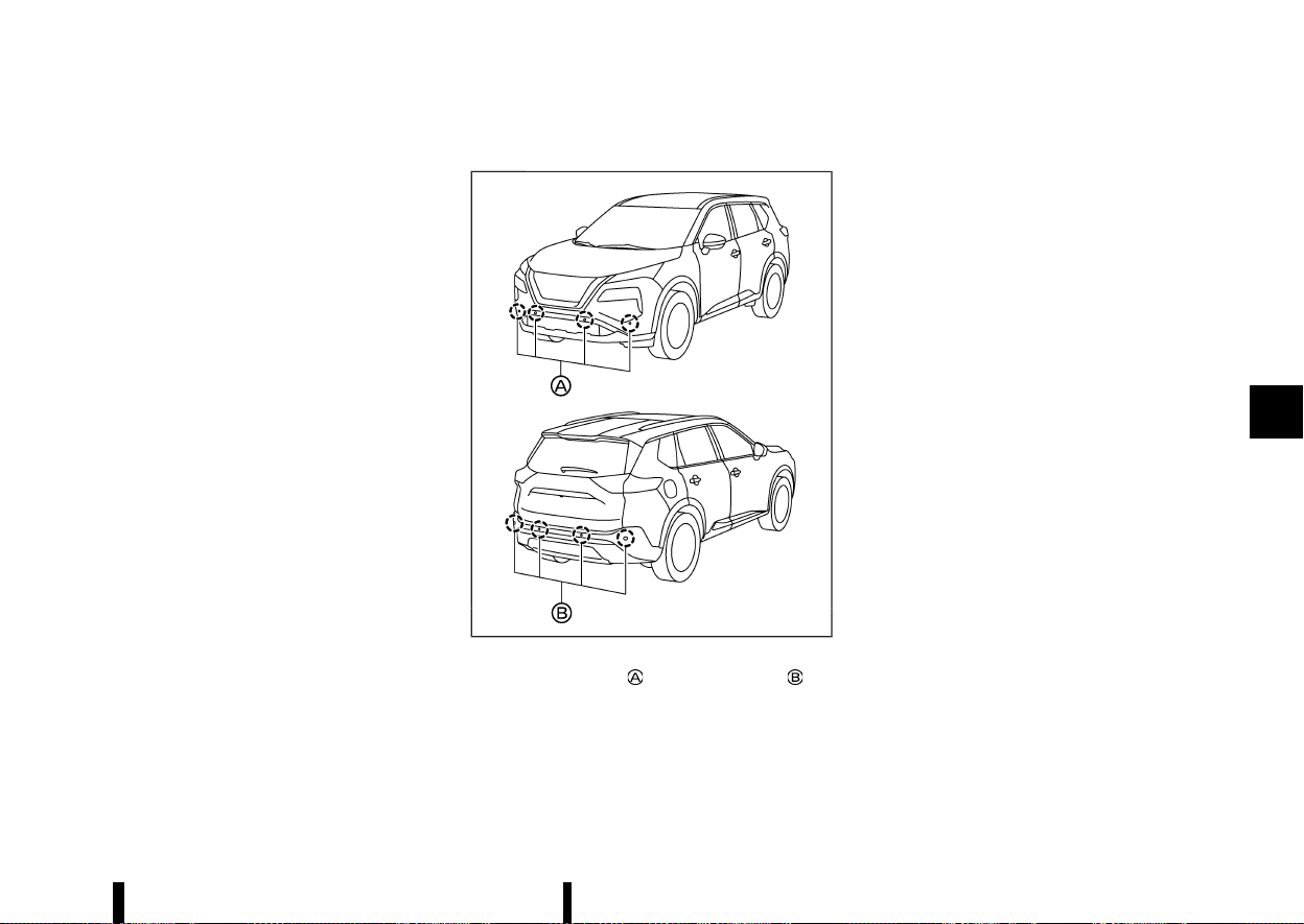
(403,1)
SYSTEM TEMPORARILY UNAVAILABLE
MEVT33A1-2E273B46-5824-487B-8A38-776BB695B2FF
When parking sensor blockage is detected, the
system will be deactivated automatically.
The system is not available until the conditions no
longer exist.
The parking sensors may be blocked by temporary
ambient conditions such as splashing water, mist
or fog. The blocked condition may also be caused
by objects such as ice, frost or dirt obstructing the
parking sensors.
Action to take:
When the above conditions no longer exist, the
system will resume automatically.
SYSTEM MAINTENANCE
MEVT33A1-825FBF93-5FBC-4227-86C3-72D377EF1692
MWAF0839X
The parking sensors (where fitted) and are
located on the bumpers.
* Always keep the area near the sensors clean.
* If the sensors are dirty, wipe them off with a
soft cloth while being careful to not damage
them.
* The sensors may be blocked by temporary
ambient conditions such as splashing water,
mist or fog. The blocked condition may also be
caused by objects such as ice, frost or dirt
obstructing the sensors. Check for and re-
move objects obstructing the area around the
sensors.
* Do not subject the area around the sensors to
strong impact. Also, do not remove or disas-
semble the sensors. If the sensors and periph-
eral areas are deformed in an accident, etc.,
have the sensors checked. It is recommended
that you visit a NISSAN dealer or qualified
workshop for this service.
* Do not attach stickers (including transparent
material), install accessories or apply addi-
tional paint on the sensors and their surround-
ing areas. This may cause a malfunction or
improper operation.
* When washing the vehicle using a high-
pressure washer, do not apply direct washer
pressure on the sensors. This may cause a
malfunction of the sensors.
Starting and driving 399

(404,1)
400 Starting and driving
MEVT33A1-5460FB5E-5751-4144-BEDA-9C44CC26E1E8
FREEING A FROZEN DOOR LOCK
MEVT33A1-C74B4044-96AE-491C-BC91-45A9ECC9A5E7
To prevent a door lock from freezing, apply deicer
through the key hole. If the lock becomes frozen,
heat the key before inserting it into the key hole, or
use the Intelligent Key system.
ANTI-FREEZE
MEVT33A1-90BFB791-C394-4902-BD39-3C2F7195DC93
In the winter when it is anticipated that the outside
temperature will drop below 0°C (32°F), check the
anti-freeze to assure proper winter protection. For
additional information, see “Engine cooling system”
(P.428) or “Intercooler cooling system” (P.429).
BATTERY
MEVT33A1-EB5AE933-122D-4608-B599-298971BE31E0
If the battery is not fully charged during extremely
cold weather conditions, the battery fluid may
freeze and damage the battery. To maintain
maximum efficiency, the battery should be
checked regularly. For additional information, see
“Battery” (P.437).
DRAINING OF COOLANT WATER
MEVT33A1-A4BF66A7-0598-4C4A-8F3F-1B3EE14A1F6A
If the vehicle is to be left outside without anti-
freeze, drain the cooling system, including the
engine block. Refill before operating the vehicle.
For details, see “Engine cooling system” (P.428).
TYRE EQUIPMENT
MEVT33A1-9C8439E1-BA84-485E-ACF6-DFC2574800D6
1. If you have snow tyres installed on the front/
rear wheels of your vehicle, they should be of
the same size, loading range, construction and
type (bias, bias-belted or radial) as the rear/
front tyres.
2. If the vehicle is to be operated in severe winter
conditions, snow tyres should be installed on
all four wheels.
3. For additional traction on icy roads, studded
tyres may be used. However, some countries,
provinces and states prohibit their use. Check
local, state and provincial laws before instal-
ling studded tyres.
Skid and traction capabilities of studded
snow tyres, on wet or dry surfaces, may be
poorer than that of non-studded snow tyres.
4. Snow chains may be used if desired. Make sure
they are the proper size for the tyres on your
vehicle and are installed according to the
chain manufacturer’s instructions. Use chain
tensioners when recommended by the tyre
chain manufacturer to ensure a tight fit. Loose
end links of the tyre chains must be secured or
removed to prevent the possibility of whipping
action damage to the fenders or underbody. In
addition, drive at a reduced speed, otherwise,
your vehicle may be damaged and/or vehicle
handling and performance may be adversely
affected.
SPECIAL WINTER EQUIPMENT
MEVT33A1-3491A18F-97B7-48DE-9D77-0C0C0BB3803C
It is recommended that the following items be
carried in the vehicle during winter:
* A scraper and stiff-bristled brush to remove
ice and snow from the windows and wiper
blades.
* A sturdy, flat board to be placed under the jack
to give it firm support.
* A shovel to dig the vehicle out of snow-drifts.
* Extra window washer fluid to refill the reser-
voir tank.
DRIVING ON SNOW OR ICE
MEVT33A1-28640823-2F38-49A8-9D56-4832A7583977
WARNING
* Wet ice (32°F, 0°C and freezing rain), very
cold snow or ice can be slick and very hard
to drive on. The vehicle will have much less
traction or “grip” under these conditions.
Try to avoid driving on wet ice until the
road is salted or sanded.
* Whatever the condition, drive with caution.
Accelerate and slow down with care. If
accelerating or downshifting too fast, the
drive wheels will lose even more traction.
* Allow more stopping distance under these
conditions. Braking should be started
sooner than on dry pavement.
* Allow greater following distances on slip-
pery roads.
* Watch for slippery spots (glare ice). These
may appear on an otherwise clear road in
shaded areas. If a patch of ice is seen
COLD WEATHER DRIVING
COLD WEATHER DRIVING
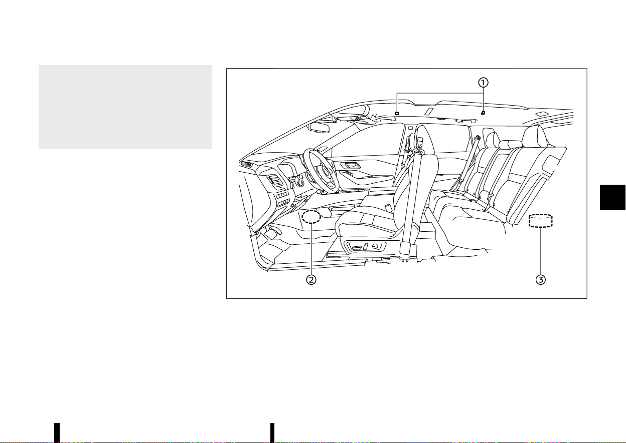
(405,1)
ahead, brake before reaching it. Try not to
brake while on the ice, and avoid any
sudden steering manoeuvres.
* Do not use cruise control on slippery roads.
* Snow can trap dangerous exhaust gases
under your vehicle. Keep snow clear of the
exhaust pipe and from around your vehi-
cle.
MEVT33A1-6DC162F3-C505-4BAE-91C8-4ECE3048609E
MWAF0784X
Example
NOTE:
To operate the active noise cancellation and
active sound enhancement system properly:
* Do not cover the speakers or woofer.
* Do not cover the microphones.
* Do not change or modify speakers including
the woofer and any audio related parts such
as the amplifier.
* Do not make any modification including sound
deadening or modifications around the micro-
phones, speakers or woofer.
Starting and driving 401
ACTIVE NOISE CANCELLATION/
ACTIVE SOUND ENHANCEMENT
ACTIVE NOISE CANCELLATION/ACTIVE SOUND ENHANCEMENT

(406,1)
402 Starting and driving
ACTIVE NOISE CANCELLATION
MEVT33A1-9C85BCAE-EFE5-48CD-8C8D-EEA3CA6520C0
The active noise cancellation uses microphones
located inside the vehicle to detect engine boom-
ing noises. The system then automatically pro-
duces a muted engine booming noise through the
speakers
and woofer to reduce engine
booming noise.
If the microphones
or the area around it is
tapped, abnormal noise may be output from the
speaker.
ACTIVE SOUND ENHANCEMENT
MEVT33A1-D580A998-6DE1-4001-A99A-ABD7957BE4F9
The active sound enhancement generates sounds
according to engine speed and driving modes
through the speakers
and woofer to enhance
the quality of the engine sound.

(407,1)
6 In case of emergency
Hazard warning flasher switch ........................................................ 404
Emergency Stop Signal .......................................................................... 404
Emergency engine shut off ................................................................. 405
Flat tyre ............................................................................................................... 405
Tyre Pressure Monitoring System (TPMS) ..................... 405
Repairing flat tyre ............................................................................. 405
Jump starting
....
............................................................................................. 409
Push starting
....
............................................................................................... 411
If your vehicle overheats
....
................................................................... 411
Towing your vehicle
....
.............................................................................. 412
Towing recommended by NISSAN
....
.................................. 413
(408,1)
404 In case of emergency
MEVT33A1-F8C8FFF6-A599-4B3B-A1E6-F9439E4BD2DC
MSIC2574
The hazard indicator flasher switch operates
regardless of the ignition switch position except
when the battery is discharged.
The hazard indicator flasher is used to warn other
drivers when you have to stop or park under
emergency conditions.
When the hazard indicator flasher switch is
pushed, all turn signal lights will flash. To turn off
the hazard indicator flasher, push the hazard
indicator flasher switch again.
When an impact that could activate the supple-
mental air bags is detected, the hazard warning
flasher lights blink automatically.
WARNING
Do not turn the hazard warning flasher switch
to off until you can make sure that it is safe to
do so. Also, the hazard flasher warning may
not blink automatically depending on the force
of impact.
If the hazard warning flasher switch is pushed, the
hazard warning flashers will turn off.
MEVT33A1-767CAB03-A2F1-4C04-AC7E-66064BCCA4BE
The Emergency Stop Signal will blink the brake
lights and high-mounted brake light to prevent the
rear-end collision, when a sudden braking opera-
tion is detected.
The Emergency Stop Signal operates in the
following conditions:
* When the vehicle speed is above 60 km/h (37
MPH)
* When the system detects a sudden braking
while the footbrake is applied
The Emergency Stop Signal will not operate in the
following conditions:
* When the hazard indicator flasher operates
* When the system does not detect a sudden
braking
HAZARD WARNING FLASHER SWITCH
HAZARD WARNING FLASHER SWITCH
EMERGENCY STOP SIGNAL
EMERGENCY STOP SIGNAL

(409,1)
MEVT33A1-7C6757DA-C9FC-43FC-9E43-9CB1131A89D7
To shut off the engine in an emergency situation
while driving, perform the following procedure:
* Rapidly push the push-button ignition switch 3
consecutive times in less than 1.5 seconds, or
* Push and hold the push-button ignition switch
for more than 2 seconds.
MEVT33A1-5D64AB92-19AE-4EBB-85E2-0500CB2054C5
TYRE PRESSURE MONITORING SYSTEM
(TPMS)
MEVT33A1-D5EFDF05-2AE3-40F2-80D4-FC9B73F45065
This vehicle is equipped with the Tyre Pressure
Monitoring System (TPMS). It monitors tyre pres-
sure of all tyres. When the low tyre pressure
warning light is lit, and the [Low Tyre Pressure]
warning message is displayed in the vehicle
information display, one or more of your tyres is
significantly under-inflated. If the vehicle is being
driven with low tyre pressure, the TPMS will
activate and warn you of it by the low tyre
pressure warning light. This system will activate
only when the vehicle is driven at speeds above 25
km/h (16 MPH). For more details, see “Warning
lights, indicator lights and audible reminders” (P.74)
and “Tyre Pressure Monitoring System (TPMS)”
(P.240).
WARNING
* If the low tyre pressure warning light
illuminates while driving, avoid sudden
steering manoeuvres or abrupt braking,
reduce vehicle speed, pull off the road to a
safe location and stop the vehicle as soon
as possible. Driving with under-inflated
tyres may permanently damage the tyres
and increase the likelihood of tyre failure.
Serious vehicle damage could occur and
may lead to an accident and could result in
serious personal injury. Check the tyre
pressure for all four tyres. Adjust the tyre
pressure to the recommended COLD tyre
pressure shown on the tyre placard to turn
the low tyre pressure warning light OFF. If
the light still illuminates while driving after
adjusting the tyre pressure, a tyre may be
flat. If you have a flat tyre, repair it with an
emergency tyre puncture repair kit as soon
as possible.
* Replacing tyres with those not originally
specified by NISSAN could affect the prop-
er operation of the TPMS.
* NISSAN recommends using only Genuine
NISSAN Emergency Tyre Sealant provided
with your vehicle. Other tyre sealants may
damage the valve stem seal which can
cause the tyre to lose air pressure. Visit a
NISSAN dealer or qualified workshop as
soon as possible after using tyre repair
sealant.
REPAIRING FLAT TYRE
MEVT33A1-0EFD9885-7F53-4D60-A5D6-B72B83F6D394
The emergency tyre puncture repair kit is supplied
with the vehicle instead of a spare tyre. This repair
kit must be used for temporarily fixing a minor tyre
puncture. After using the repair kit, see a NISSAN
dealer or qualified workshop as soon as possible
for tyre inspection and repair/replacement.
CAUTION
* NISSAN recommends using only Genuine
NISSAN Emergency Tyre Sealant provided
with your vehicle. Other tyre sealants may
damage the valve stem seal which can
cause the tyre to lose air pressure.
* Do not use the emergency tyre puncture
repair kit provided with your vehicle on
other vehicles.
* Do not use the emergency tyre puncture
In case of emergency 405
EMERGENCY ENGINE SHUT OFF
EMERGENCY ENGINE SHUT OFF
FLAT TYRE
FLAT TYRE
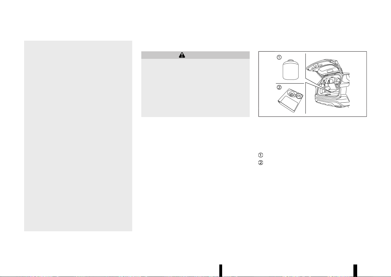
(410,1)
406 In case of emergency
repair kit for a purpose other than to
inflate and check the tyre pressure for
the vehicle.
* Use the emergency tyre puncture repair kit
only on DC12V.
* Keep water and dust off the emergency
tyre puncture repair kit.
* Do not disassemble or modify the emer-
gency tyre puncture repair kit.
* Do not galvanise the emergency tyre
puncture repair kit.
* Do not use the emergency tyre puncture
repair kit under the following conditions.
Contact a NISSAN dealer or qualified work-
shop or professional road assistance.
— when the sealant has passed its expira-
tion date (shown on the label attached to
the bottle)
— when the cut or the puncture is approxi-
mately 6 mm (0.25 in) or longer
— when the side of the tyre is damaged
— when the vehicle has been driven with a
considerable loss of air from the tyre
— when the tyre is completely displaced
inside or outside the rim
— when the tyre rim is damaged
— when two or more tyres are flat
Stopping vehicle
MEVT33A1-373EA566-1B6F-498D-9FE6-B2F0FD090F8B
WARNING
* Make sure the parking brake is securely
applied and the vehicle is placed into the P
(Park) position.
* Never repair tyres when the vehicle is on a
slope, ice or slippery area. This is hazar-
dous.
* Never repair tyres when the oncoming
traffic is close to your vehicle. Call for
professional road assistance.
1. Safely move the vehicle off the road away from
traffic.
2. Turn on the hazard indicator flasher lights.
3. Park on a level surface.
4. Apply the parking brake.
5. Push the park button to shift to the P (Park)
position.
6. Place the ignition switch in the “OFF” position.
7. Open the bonnet and set up the warning
triangle (where fitted):
.
To warn other traffic.
.
To signal professional road assistance per-
sonnel that you need assistance.
8. Have all passengers get out from the vehicle
and stand in a safe place, away from other
traffic and clear of the vehicle.
Getting emergency tyre puncture repair kit
MEVT33A1-8240377E-0C5C-4B51-9A82-BF5E7E84FBB0
MWAG0176X
Example
Take out the emergency tyre puncture repair kit
from the storage area under the luggage floor
board. The repair kit consists of the following
items:
Tyre sealant bottle
Air compressor*
*: The compressor shape may differ depending on
the models.
Before using emergency tyre puncture repair kit
MEVT33A1-B0794B66-8DBA-4843-8D2A-AC4C648813E3
* If any foreign object (for example, a screw or
nail) is embedded in the tyre, do not remove it.
* Check the expiration date of the sealant
(shown on the label attached to the bottle).
Never use a sealant whose expiration date has
passed.
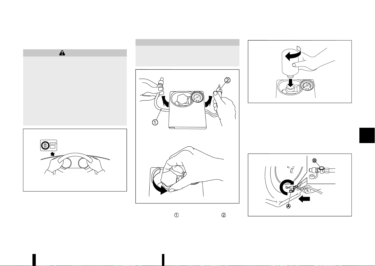
(411,1)
Repairing tyre
MEVT33A1-113CE38E-9DBB-47E6-AED6-B20991EAF4F2
WARNING
Observe the following precautions when using
the emergency tyre puncture repair kit.
* Swallowing the compound is dangerous.
Immediately drink as much water as pos-
sible and seek prompt medical assistance.
* Rinse well with lots of water if the com-
pound comes into contact with skin or
eyes. If irritation persists, seek prompt
medical attention.
* Keep the repair compound out of the reach
of children.
MJVE0014X
1. Take out the speed restriction sticker from the
air compressor*, then put it in a location where
the driver can see it while driving.
*: The compressor shape may differ depending
on the models.
CAUTION
Do not put the speed restriction label on the
steering wheel pad, the speedometer or the
warning light locations.
MWAG0161X
2. Take the hose and the power plug out of
the air compressor. Remove the cap of the
bottle holder from the air compressor.
MWAG0162X
3. Remove the cap of the tyre sealant bottle, and
screw the bottle clockwise onto the bottle
holder. (Leave the bottle seal intact. Screwing
the bottle onto the bottle holder will pierce the
seal of the bottle.)
4. Remove the cap of the tyre valve on the flat
tyre.
MSCE0870
In case of emergency 407
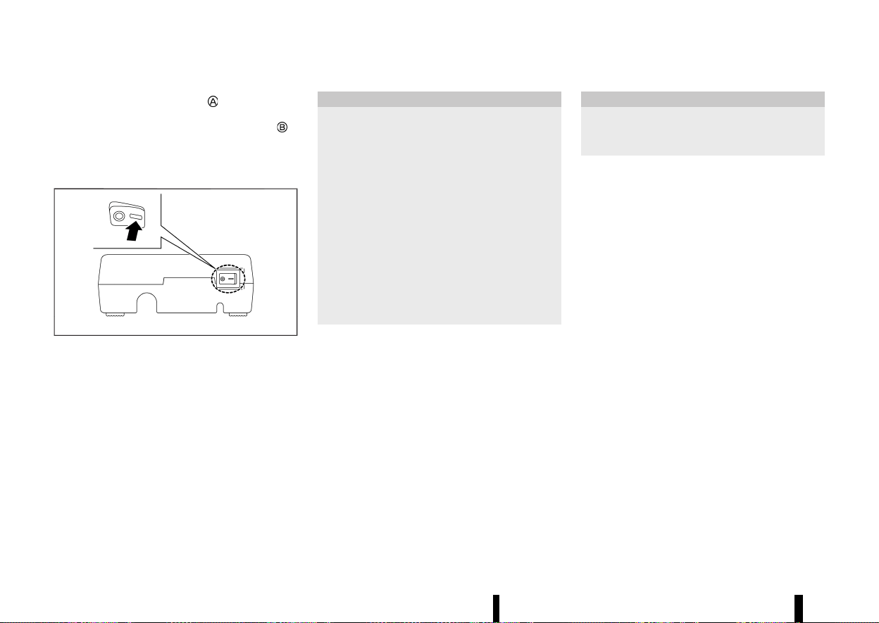
(412,1)
408 In case of emergency
5. Remove the protective cap of the hose and
screw the hose securely onto the tyre valve.
Make sure that the pressure release valve
is
securely tightened. Make sure that the air
compressor switch is in the OFF (*) position,
and then insert its power plug into the power
outlet in the vehicle.
MWAG0163X
6. Place the ignition switch in the ON position.
Then turn the compressor switch to the ON (−)
position and inflate the tyre up to the pressure
that is specified on the tyre placard affixed to
the driver’s side centre pillar if possible, or to
the minimum of 180 kPa (26 psi). Turn the air
compressor off briefly in order to check the
tyre pressure with the pressure gauge.
If the tyre is inflated to higher than the
specified pressure, adjust the tyre pressure
by releasing air with the pressure release
valve. The cold tyre pressures are shown on
the tyre placard affixed to the driver’s side
centre pillar.
CAUTION
* An incomplete connection between the
hose and tyre valve causes air leakage or
sealant scatter.
* Do not stand directly beside the damaged
tyre while it is being inflated because of
the risk of the rupture. If there are any
cracks or bumps, turn the compressor off
immediately.
* There is a possibility that the pressure
reaches 600 kPa (87 psi) while the tyre is
being inflated, but it is normal condition.
Usually the pressure will drop in about 30
seconds.
* Do not operate the compressor for more
than 10 minutes.
If the tyre pressure does not increase to 180
kPa (26 psi) within 10 minutes, the tyre may
be seriously damaged and the tyre cannot be
repaired with this tyre puncture repair kit.
Contact a NISSAN dealer or qualified work-
shop.
7. When the tyre pressure is reaching the speci-
fied pressure or is at the minimum of 180 kPa
(26 psi), turn the air compressor off. Remove
the power plug from the power outlet and
quickly remove the hose from the tyre valve.
Attach the protective cap and valve cap.
CAUTION
Leave the tyre sealant bottle on the bottle
holder in order to prevent sealant from spilling
out.
8. Immediately drive the vehicle for 10 minutes or
3 km (2 miles) at a speed of 80 km/h (50 MPH)
or less.
9. After driving, make sure that the air compres-
sor switch is in the OFF (*) position, then
screw the hose securely onto the tyre valve.
Check the tyre pressure with the pressure
gauge.
If the tyre pressure drops under 130 kPa (19 psi):
The tyre cannot be repaired with this tyre
puncture repair kit. Contact a NISSAN dealer or
qualified workshop.
If the tyre pressure is 130 kPa (19 psi) OR MORE
BUT LESS THAN THE SPECIFIED PRESSURE:
Turn the compressor switch to the ON ( — )
position and inflate the tyre up to the specified
pressure. Then repeat the steps from 8.
If the pressure drops again, the tyre cannot be
repaired with this tyre puncture repair kit.
Contact a NISSAN dealer or qualified workshop.
When the tyre pressure is the specified pressure:
The temporary repair is completed.
See a NISSAN dealer or qualified workshop for tyre
repair/replacement as soon as possible.

(413,1)
CAUTION
Do not reuse the tyre sealant bottle or the
hose.
For a new tyre sealant bottle and hose, see a
NISSAN dealer or qualified workshop.
After repairing tyre
MEVT33A1-D4ED23E6-2F64-4F5F-AAB0-17E92D4105BE
See a NISSAN dealer or qualified workshop for tyre
repair/replacement as soon as possible.
MEVT33A1-EFD5543C-B96C-4978-B4C8-DDC9E8689D5B
To start your engine with a booster battery, the
instructions and precautions below must be fol-
lowed.
WARNING
* If done incorrectly, jump starting can lead
to a battery explosion, resulting in severe
injury or death. It could also damage your
vehicle.
* Explosive hydrogen gas is always present
in the vicinity of the battery. Keep all
sparks and flames away from the battery.
* Do not allow battery fluid to come into
contact with eyes, skin, clothing or painted
surfaces. Battery fluid is a corrosive sul-
phuric acid solution which can cause
severe burns. If the fluid should come into
contact with anything, immediately flush
the contacted area with water.
* Keep the battery out of the reach of
children.
* The booster battery must be rated at 12
volts. Use of an improperly rated battery
can damage your vehicle.
* Whenever working on or near a battery,
always wear suitable eye protectors (for
example, goggles or industrial safety spec-
tacles) and remove rings, metal bands, or
any other jewellery. Do not lean over the
battery when jump starting.
* Do not attempt to jump start a frozen
battery. It could explode and cause serious
injury.
* Your vehicle has an automatic engine
cooling fan. It could come on at any time.
Keep hands and other objects away from
it.
This vehicle has 2 batteries, a 12-volt battery (main)
and a Lithium ion (Li-ion) battery (auxiliary). The
engine cannot be started if the main battery is
discharged. Apply the following procedure to the
main battery to jump start the engine.
When connecting the jumper cables, it is required
to use the booster vehicle equipped with the 12-
volt battery. If the cables are connected to the
battery at the rate of more than 12 volts, the
vehicle may be damaged when the cables are
connected incorrectly.
In case of emergency 409
JUMP STARTING
JUMP STARTING

(414,1)
410 In case of emergency
MWAG0123X
WARNING
Always follow the instructions below. Failure to
do so could result in damage to the charging
system and cause personal injury.
1. If the booster battery is in another vehicle
,
position the two vehicles (
and ) to bring
their batteries into close proximity to each
other.
Do not allow the two vehicles to touch.
2. Apply the parking brake.
3. Push the park button to engage the P (Park)
position.
4. Switch off all unnecessary electrical systems
(headlights, heater, air conditioner, etc.).
5. Connect jumper cables in the sequence as
illustrated (
? ? ? ).
CAUTION
* Always connect positive (+) to positive (+)
and negative (−) to body ground (for
example, as illustrated), not to the battery.
* Make sure the jumper cables do not touch
moving parts in the engine compartment
and that the cable clamps do not contact
any other metal.
6. Start the engine of the booster vehicle
and
let it run for a few minutes.
7. Keep the engine speed of the booster vehicle
at about 2,000 rpm, and start the engine of
the vehicle
being jump started.
CAUTION
Do not keep the starter motor engaged for
more than 10 seconds. If the engine does not
start right away, place the ignition switch in
the “OFF” position and wait 10 seconds before
trying again.
8. After starting your engine, carefully disconnect
the negative cable and then the positive cable
(
? ? ? ).
NOTE:
Use the special 12-volt battery (main battery)
that is enhanced in regard to the charge-
discharge capacity and life performance. Avoid

(415,1)
using a non-special battery for this vehicle as
this may cause early deterioration of the battery
or a malfunction of the Stop/Start and the Smart
simple hybrid systems. For the battery, it is
recommended to use Genuine NISSAN parts. For
more information, contact a NISSAN dealer or
qualified workshop.
MEVT33A1-A764C60A-F34B-45BD-8A21-83DCBF259F31
Do not attempt to start the engine by pushing.
CAUTION
* Continuously Variable Transmission (CVT)
models cannot be push-started or tow-
started. Attempting to do so may cause
transmission damage.
* Three-way catalyst equipped models
should not be started by pushing since
the three way catalyst may be damaged.
* Never try to start the vehicle by towing it;
when the engine starts, the forward surge
could cause the vehicle to collide with the
tow vehicle.
MEVT33A1-706E277F-8F75-437A-8E9B-3AA46086CF31
WARNING
* Never continue driving if your vehicle over-
heats. Doing so could cause a vehicle fire.
* Never open the bonnet if steam is coming
out.
* Never remove the radiator or coolant
reservoir cap while the engine is hot. If
the radiator or coolant reservoir cap is
removed when the engine is hot, pres-
surised hot water will spurt out and possi-
bly cause burning, scalding or serious
injury.
* If steam or coolant is coming from the
engine, stand clear of the vehicle to pre-
vent getting burned.
* The engine cooling fan will start at anytime
when the coolant temperature exceeds
preset degrees.
* Be careful not to allow your hands, hair,
jewellery or clothing to come into contact
with, or to get caught in the cooling fan or
drive belts.
If your vehicle is overheating (indicated by an
extremely high temperature gauge reading), or if
you feel a lack of engine power, detect abnormal
noise, etc., take the following steps:
1. Move the vehicle safely off the road and apply
the parking brake.
2. Push the park button to shift to the P (Park)
position.
Do not stop the engine.
In case of emergency 411
PUSH STARTING
PUSH STARTING
IF YOUR VEHICLE OVERHEATS
IF YOUR VEHICLE OVERHEATS

(416,1)
412 In case of emergency
3. Turn off the air conditioner. Open all the
windows, move the heater or air conditioner
temperature control to maximum hot and fan
control to high speed.
4. Get out of the vehicle. Look and listen for
steam or coolant escaping from the radiator
or coolant reservoir before opening the bon-
net. (If steam or coolant is escaping, turn off
the engine.) Do not open the bonnet further
until no steam or coolant can be seen.
5. Open the engine bonnet.
WARNING
If steam or water is coming from the engine,
stand clear to prevent getting burned.
6. Visually check the drive belt for damage or
looseness. Also check if the cooling fan is
running. The radiator hoses and radiator
should not leak water. If coolant is leaking or
the cooling fan does not run, stop the engine.
WARNING
Be careful not to allow your hands, hair,
jewellery or clothing to come into contact with,
or get caught in, engine belts or the engine
cooling fan. The engine cooling fan can start at
any time.
7. After the engine cools down, check the cool-
ant level in the reservoir with the engine
running. Add coolant to the reservoir if neces-
sary. Have your vehicle repaired by a NISSAN
dealer or qualified workshop.
MEVT33A1-9C3082E6-7E05-4D3B-99BC-7AC9A9D1154A
When towing your vehicle, local regulations for
towing must be followed. Incorrect towing equip-
ment could damage your vehicle. To assure proper
towing and to prevent accidental damage to your
vehicle, NISSAN recommends that you have pro-
fessional road assistance personnel tow your
vehicle. It is advisable to have the professional
road assistant carefully read the following precau-
tions.
WARNING
* Never ride in a vehicle that is being towed.
* Never get under your vehicle after it has
been lifted by a tow truck.
CAUTION
* When towing, make sure that the trans-
mission, axles, steering system and power-
train are in working condition. If any of
these conditions apply, dollies or a flatbed
tow truck must be used.
* Always attach safety chains before towing.
NOTE:
If the battery is completely drained, the trans-
mission will not manually shift to other posi-
tions. For shifting to other positions, charge the
battery or supply power following the jump
starting procedure. Push the park button to
shift to the P (Park) position before shifting to
other positions.
TOWING YOUR VEHICLE
TOWING YOUR VEHICLE
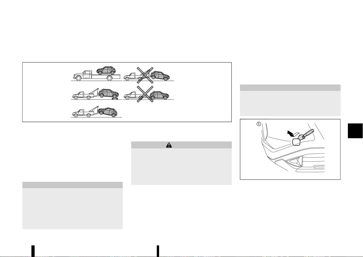
(417,1)
TOWING RECOMMENDED BY NISSAN
MEVT33A1-09B962BF-4170-4F2F-83C9-E1E70F0C2C59
Two-Wheel Drive (2WD) MODELS
MEVT33A1-52826B00-51B3-4A50-B898-5192FE87088D
MSCE0950
NISSAN recommends that your vehicle be towed
with the driving (front) wheels off the ground or
place the vehicle on a flat bed truck as illustrated.
NOTE:
If the electronic parking brake is released, the
rear wheels can be grounded while towing. If the
electronic parking brake is not released, towing
dollies should be used. For additional informa-
tion, refer to “Parking brake” (P.171).
CAUTION
Never tow CVT models with the front wheels on
the ground or four wheels on the ground
(forward or backward), as this may cause
serious and expensive damage to the trans-
mission. If it is necessary to tow the vehicle
with the rear wheels raised, always use towing
dollies under the front wheels.
Freeing trapped vehicle
MEVT33A1-A7A2EF29-B6E7-4DCA-B2BF-83D68E207523
WARNING
* Never allow anyone to stand near the
towing line during the pulling operation.
* Never spin the tyres at high speed. This
could cause them to explode and result in
serious injury. Parts of the vehicle could
also overheat and be damaged.
In the event that your vehicle’s tyres become
trapped in sand, snow, or mud, and the vehicle is
unable to free itself without being pulled, use the
recovery hook.
* Use the recovery hook only. Do not attach the
pulling device to any other part of the vehicle
body. Otherwise, the vehicle body may be
damaged.
* Use the recovery hook to free a vehicle only.
* The recovery hook is under tremendous stress
when used to free a trapped vehicle. Always
pull the pulling device straight out from the
vehicle. Never pull on the recovery hook at an
angle.
CAUTION
There are two hooks in the storage area. Use
the longer hook for front, and shorter hook for
rear. If the different hook is used, the vehicle
and the hook may be damaged.
MWAG0129X
Front
In case of emergency 413
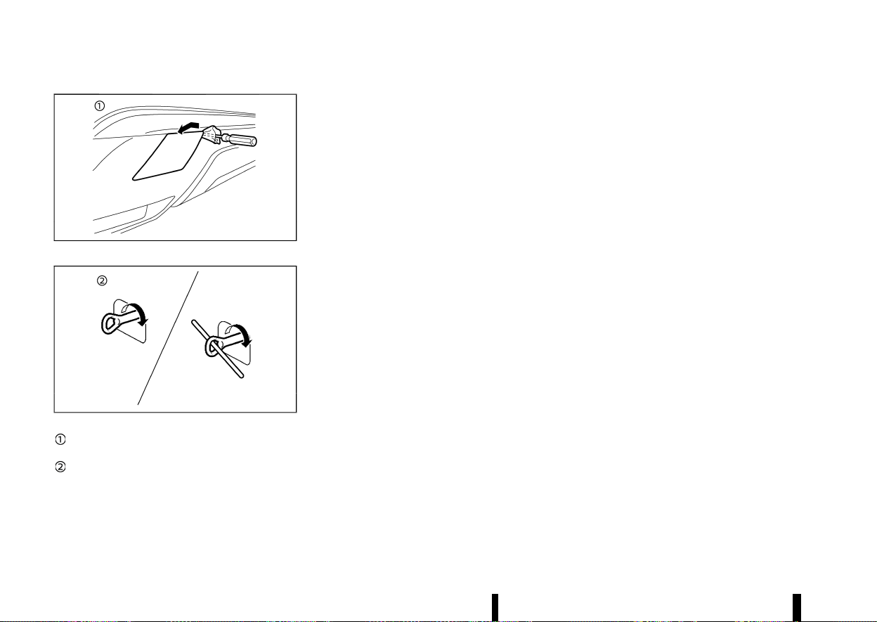
(418,1)
414 In case of emergency
MWAG0177X
Rear
MWBG0033X
Remove the hook cover from the bumper
with a suitable tool.
Securely install the recovery hook as illu-
strated. (The hook is stored in the storage
area under the luggage board.)
Make sure that the recovery hook is properly
secured in its storage area after use.

(419,1)
7 Appearance and care
Cleaning exterior ......................................................................................... 416
Washing ..................................................................................................... 416
Removing spots .................................................................................. 416
Waxing ........................................................................................................ 416
Glass ............................................................................................................ 417
Underbody .............................................................................................. 417
Wheels ........................................................................................................ 417
Aluminium alloy wheels ............................................................... 417
Chrome parts ....................................................................................... 417
Cleaning interior ........................................................................................... 417
Air fresheners ....................................................................................... 418
Floor mats
....
........................................................................................... 418
Glass
....
........................................................................................................ 418
Seat belts
....
............................................................................................. 418
Corrosion protection
....
............................................................................ 419
Most common factors contributing to
vehicle corrosion
....
........................................................................... 419
Environmental factors influence rate
of corrosion
....
....................................................................................... 419
To protect your vehicle from corrosion
....
..................... 419

(420,1)
416 Appearance and care
MEVT33A1-6E457B81-64FD-45D4-AABB-D085CE756A65
In order to maintain the appearance of your
vehicle, it is important to take proper care of it.
Whenever possible, park your vehicle inside a
garage or in a covered area to minimise the
chances of damaging the paint surface of your
vehicle.
When it is necessary to park outside, park in a
shady area or protect the vehicle with a body
cover. Be careful not to scratch the paint surface
when putting on or removing the body cover.
WASHING
MEVT33A1-A37F2FA5-EE98-459F-B15C-59568EB0BE6E
In the following instances, wash your vehicle as
soon as possible to protect the paint surface:
* After a rainfall, which may cause the paint
surface damage from acid rain.
* After driving on coastal roads, which may
cause rusting from the sea breeze.
* When contaminants such as soot, bird drop-
pings, tree sap, metal particles or bugs get on
the paint surface.
* When dust or mud builds up on the paint
surface.
1. Wash the vehicle surface with a wet sponge
and plenty of water.
2. Clean the vehicle surface gently and thor-
oughly using a mild soap, a special vehicle
soap or a general purpose dishwashing liquid
mixed with clean, lukewarm (never hot) water.
CAUTION
* Do not wash the vehicle with strong
household soap, strong chemical deter-
gents, petrol or solvents.
* Do not wash the vehicle in direct sunlight
or while the vehicle body is hot, as the
paint surface may become water-spotted.
* Avoid using tight-napped or rough cloths,
such as washing mitts. Care must be taken
when removing caked-on dirt or other
foreign substances so the paint surface is
not scratched or damaged.
* Do not wash the engine compartment.
Doing so may cause a failure in engine
starting or a malfunction. If water is
sprinkled to the electrical parts, it may
result in a short circuit and could cause a
fire.
3. Rinse the vehicle thoroughly with plenty of
clean water.
4. Use a dampened chamois to dry the paint
surface and avoid leaving water spots.
When washing the vehicle, take care of the
following:
* Inside flanges, joints and folds on the doors,
hatches and bonnet are particularly vulner-
able to the effects of road salt. Therefore,
these areas must be cleaned regularly.
* Be sure that the drain holes in the lower edge
of the doors are not clogged.
* Spray water to the underbody and in the
wheel wells to loosen the dirt and/or wash
away road salt.
REMOVING SPOTS
MEVT33A1-38082774-5DB0-4367-A59E-9B1E301989DB
Remove tar and oil spots, industrial dust, insects,
and tree sap as quickly as possible from the paint
surface to avoid lasting damage or staining.
Special cleaning products are available at a NISSAN
dealer or qualified workshop or any automotive
accessory store.
WAXING
MEVT33A1-8475D1EA-C7C2-4187-9B29-68D75E443CF2
Regular waxing protects the paint surface and
helps maintain a new vehicle appearance.
After waxing, polishing is recommended to remove
built-up residue and to avoid a weathered appear-
ance.
A NISSAN dealer or qualified workshop can assist
you in choosing the appropriate waxing products.
CAUTION
* Wash your vehicle thoroughly and com-
pletely before applying wax to the paint
surface.
* Always follow the manufacturer’s instruc-
tions supplied with the wax.
* Do not use a wax containing any abrasives,
cutting compounds or cleaners that may
damage the vehicle finish.
Machine compounding or aggressive polishing on
a base coat/clear coat paint finish may dull the
finish or leave swirl marks.
CLEANING EXTERIOR
CLEANING EXTERIOR

(421,1)
GLASS
MEVT33A1-A5BB1415-C2AF-4945-AD84-E53DD87C2807
Use glass cleaner to remove smoke and dust film
from the glass surfaces. It is normal for glass to
become coated with a film after the vehicle is
parked in the hot sun. Glass cleaner and a soft
cloth will easily remove this film.
UNDERBODY
MEVT33A1-85F11A62-81BC-4A90-8F5E-E26104177B9F
In areas where road salt is used in the winter, it is
necessary to clean the vehicle’s underbody reg-
ularly in order to prevent dirt and salt from building
up and causing the acceleration of corrosion on
the underbody and suspension.
Before the winter and again in the spring, the
underseal must be checked and, if necessary, re-
treated.
WHEELS
MEVT33A1-47721BC4-4E82-4C10-9EF9-8999944FF913
* Wash the wheels when washing the vehicle to
maintain their appearance.
* Clean the inner side of the wheels when the
wheel is changed or the underside of the
vehicle is washed.
* Do not use abrasive cleaners when washing
the wheels.
* Inspect wheel rims regularly for dents or
corrosion. This may cause loss of pressure or
damage the tyre bead.
* NISSAN recommends that the road wheels be
waxed to protect against road salt in areas
where it is used during winter.
ALUMINIUM ALLOY WHEELS
MEVT33A1-57FE2E28-91F0-4A3F-B0B0-34395A817574
Wash the wheels regularly with a sponge dam-
pened in a mild soap solution, especially during
winter in areas where road salt is used. The salt
residue from road salt could discolor the wheels if
it is not washed off regularly.
CAUTION
Follow the directions below to avoid staining
or discoloring the wheels:
* Do not use a cleaner that uses strong acid
or alkali contents to clean the wheels.
* Do not apply wheel cleaners to the wheels
when they are hot. The wheel temperature
should be the same as ambient tempera-
ture.
* Rinse the wheel to completely remove the
cleaner within 15 minutes after the cleaner
is applied.
CHROME PARTS
MEVT33A1-174885A1-F19D-42A3-8822-22357FD4D865
Clean all chrome parts regularly with a nonabra-
sive chrome polish to maintain the finish.
MEVT33A1-2D22F4A7-9931-41A5-87D2-F42BD2240FAC
Occasionally remove loose dust from the interior
trim, plastic parts and seats using a vacuum
cleaner or soft bristled brush. Wipe the vinyl and
leather surfaces with a clean, soft cloth dampened
in mild soap solution, then wipe clean with a dry,
soft cloth.
Regular care and cleaning is required in order to
maintain the appearance of the leather.
Before using any fabric protector, read the man-
ufacturer’s recommendations. Some fabric protec-
tors contain chemicals that may stain or bleach
the seat material.
Use a soft cloth dampened only with water to
clean the meter and gauge lens covers.
WARNING
Do not use water or acidic cleaners (hot steam
cleaners) on the seat. This can damage the
seat or occupant classification sensors. This
can also affect the operation of the air bag
system and result in serious personal injury.
CAUTION
* Never use benzine, thinner or any similar
material.
* Small dirt particles can be abrasive and
damaging to leather surfaces and should
be removed promptly. Do not use saddle
soap, car waxes, polishes, oils, cleaning
fluids, solvents, detergents or ammonia-
based cleaners as they damage the leather
natural finish.
* Never use fabric protectors unless recom-
mended by the manufacturer.
Appearance and care 417
CLEANING INTERIOR
CLEANING INTERIOR
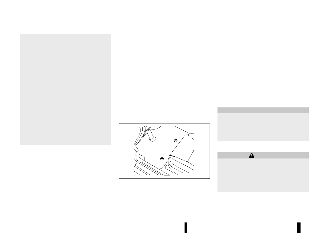
(422,1)
418 Appearance and care
* Do not use glass or plastic cleaner on
meter or gauge lens covers. It may da-
mage the lens covers.
* Do not spill on or make contact with
interior surfaces while handling air fresh-
eners, aroma agents, cosmetics, sunsc-
reen, etc. They may cause permanent
discoloration, stain, crack, paint peeling,
etc. depending on the ingredients. If they
contact the interior surface, wipe them off
immediately using a soft cloth.
* Do not use the chlorine-based cleaning
liquid such as chlorine dioxide and hypo-
chlorous acid, which may cause the paint
peeling, corrosion, etc. If it is unavoidable
to clean or sterilize interior surfaces, use
less than 75% ethanol. Wipe the interior
parts with a dry cloth dampened with
ethanol. Wipe off ethanol completely. If
you leave it uncleaned, it may cause paint
peeling, discoloration, etc. Since ethanol is
flammable, be careful of fire.
AIR FRESHENERS
MEVT33A1-9EFF2C9A-CA9A-4251-8C7E-A9FF7C4B01E6
Most air fresheners use a solvent that could affect
the vehicle interior. If you use an air freshener, take
the following precautions:
* Hanging-type air fresheners can cause perma-
nent discoloration when they contact vehicle
interior surfaces. Place the air freshener in a
location that allows it to hang free and not
contact an interior surface.
* Liquid-type air fresheners typically clip on the
vents. These products can cause immediate
damage and discoloration when spilled on
interior surfaces.
Carefully read and follow the manufacturer’s
instructions before using air fresheners.
FLOOR MATS
MEVT33A1-84C6015E-6639-4203-BFF2-648747F1FE09
The use of genuine NISSAN floor mats (where
fitted) can extend the life of your vehicle carpet
and make it easier to clean the interior. Regardless
of what mats are used, be sure they are fitted for
your vehicle and are properly positioned in the foot
well to prevent interference with pedal operation.
Mats should be maintained with regular cleaning
and replaced if they become excessively worn.
Floor mat positioning aid
MEVT33A1-87FB63F5-179C-4735-AEC6-1917CEBBBE9F
MJVA0032X
This vehicle includes front floor mat brackets to
act as a floor mat positioning aid. NISSAN floor
mats have been specially designed for your vehicle
model.
Position the mat by placing the floor mat bracket
hook(s) through the floor mat grommet hole while
centering the mat in the foot area.
Push the grommet hole into the hook firmly and
secure it.
Periodically check that the mats are properly
positioned.
GLASS
MEVT33A1-A3E90D55-D0E3-4B01-AD63-D8AB3B816EAB
Use glass cleaner to remove smoke and dust film
from the glass surfaces. It is normal for glass to
become coated with a film after the vehicle is
parked in the hot sun. Glass cleaner and a soft
cloth will easily remove this film.
CAUTION
When cleaning the inside of the windows, do
not use sharp-edged tools, abrasive cleaners
or chlorine-based disinfectant cleaners. They
could damage the electrical conductors, such
as rear window defogger elements.
SEAT BELTS
MEVT33A1-15200638-B998-4F4F-8ACA-5B39676730CB
WARNING
* Do not allow wet seat belts to roll up in the
retractor.
* Never use bleach, dye or chemical solvents
to clean the seat belts, since these materi-
als may severely weaken the seat belt
webbing.
The seat belts can be cleaned by wiping them with
a sponge dampened in a mild soap solution.

(423,1)
Allow the belts to dry completely in the shade
before using them. (See “Seat belts” (P.28).)
MEVT33A1-BEBBED6E-CE33-49CE-B7CC-720832C408D5
MOST COMMON FACTORS CONTRI-
BUTING TO VEHICLE CORROSION
MEVT33A1-852EEE37-40BE-4E3C-A40C-A0C64AA7839E
* The accumulation of moisture-retaining dirt
and debris in body panel sections, cavities, and
other areas.
* Damage to the paint surface and other
protective coatings caused by gravel and
stone chips or minor traffic accidents.
ENVIRONMENTAL FACTORS INFLUENCE
RATE OF CORROSION
MEVT33A1-250B605B-1880-437B-AEBC-04744C309F31
Moisture
MEVT33A1-6FF97E98-825F-4BE6-B17D-1B0BE8F632ED
The accumulation of sand, dirt and water on the
inside floor of the vehicle can accelerate corrosion.
Wet floor carpet/floor mats will not dry completely
inside the vehicle. They should be removed and
completely dried to avoid floor panel corrosion.
Relative humidity
MEVT33A1-FD078763-A1E0-4C87-B305-9F19F8BA52AF
Corrosion will be accelerated in areas of high
relative humidity.
Temperature
MEVT33A1-399FD53D-CC7C-4FFE-BE14-D64B208AED09
High temperatures accelerate the rate of corrosion
to those parts which are not well ventilated.
Corrosion will also be accelerated in areas where
the temperatures stay above freezing.
Air pollution
MEVT33A1-F028D9FF-CEF1-45B5-9DF3-D3A98DB3430C
Industrial pollution, the presence of salt in the air in
coastal areas, or heavy road salt use accelerates
the corrosion process. Road salt also accelerates
the disintegration of paint surfaces.
TO PROTECT YOUR VEHICLE FROM
CORROSION
MEVT33A1-55F475F4-B036-49DD-A3EE-452807980348
* Wash and wax your vehicle often to keep the
vehicle clean.
* Always check for minor damage to the paint
surface and if any exists, repair it as soon as
possible.
* Keep the drain holes in the lower edge of the
doors open to avoid water accumulation.
* Check the vehicle underbody for accumulation
of sand, dirt or salt. If present, wash with water
as soon as possible.
CAUTION
* Never remove dirt, sand or other debris
from the passenger compartment by
washing it out with a hose. Remove dirt
with a vacuum cleaner or broom.
* Never allow water or other liquids to come
in contact with electronic components in-
side the vehicle as this may damage them.
Chemicals used for road surface deicing are
extremely corrosive. They accelerate corrosion
and deterioration of underbody components such
as the exhaust system, fuel and brake lines, brake
cables, floor pan and fenders.
In the winter, the underbody must be cleaned
periodically.
For additional protection against rust and corro-
Appearance and care 419
CORROSION PROTECTION
CORROSION PROTECTION

(424,1)
420 Appearance and care
sion, which may be required in some areas, consult
a NISSAN dealer or qualified workshop.

(425,1)
8 Maintenance and do-it-yourself
Maintenance requirements ................................................................. 423
General maintenance .................................................................... 423
Scheduled maintenance .............................................................. 423
Where to go for service ................................................................ 423
General maintenance ............................................................................... 423
Explanation of general maintenance items ................ 423
Maintenance precautions ........................................................... 425
Engine compartment check locations ....................................... 427
KR15DDT engine model .............................................................. 427
Engine cooling system ............................................................................ 428
Checking engine coolant level ............................................... 428
Changing engine coolant ........................................................... 428
Intercooler cooling system .................................................................. 429
Checking intercooler coolant level ..................................... 429
Changing intercooler coolant ................................................. 429
Engine oil ........................................................................................................... 430
Checking engine oil level ............................................................ 430
Changing engine oil and filter ................................................ 430
Drive belt ............................................................................................................ 432
Spark plugs ...................................................................................................... 432
Replacing spark plugs ................................................................... 432
Brakes ................................................................................................................... 433
Checking parking brake .............................................................. 433
Checking footbrake ......................................................................... 433
Brake fluid ......................................................................................................... 434
Continuously Variable Transmission (CVT) fluid .................. 434
Air cleaner ........................................................................................................... 435
Wiper blades ...................................................................................................... 436
Windscreen wiper blades .............................................................. 436
Rear window wiper blade ............................................................. 436
Window washer fluid .................................................................................. 437
Battery .................................................................................................................... 437
Vehicle battery ...................................................................................... 437
Jump starting ......................................................................................... 439
Intelligent Key battery ..................................................................... 439
Variable voltage control system ....................................................... 441
Fuses ....................................................................................................................... 441
Engine compartment ....................................................................... 441
Passenger compartment .............................................................. 442
Lights ....................................................................................................................... 444
Headlights ................................................................................................. 445
Exterior and interior lights ........................................................... 445
Legal requirement to adjust headlight beam .............. 446
Tyres and Wheels .......................................................................................... 448
Tyre Pressure Monitoring System (TPMS) ....................... 448
Tyre inflation pressure .................................................................... 448
Types of tyres ........................................................................................ 448
Tyre chains ............................................................................................... 448
Tyre rotation ........................................................................................... 449
Tyre wear and damage .................................................................. 449

(426,1)
Tyre age .................................................................................................... 449
Changing tyres and wheels ...................................................... 450
Wheel balance ...................................................................................... 450
Jacking up vehicle and replacing tyres ........................... 450
Emergency tyre puncture repair kit ................................... 454

(427,1)
MEVT33A1-9EAAEAA8-B9FF-43F0-B734-1F3E7455FBA3
Some day-to-day and regular maintenance is
essential to maintain your vehicle’s good mechan-
ical condition, as well as its emission and engine
performance.
It is the owner’s responsibility to make sure that
the specified maintenance, as well as general
maintenance, is performed.
As the vehicle owner, you are the only one who can
ensure that your vehicle receives the proper
maintenance care.
GENERAL MAINTENANCE
MEVT33A1-22087F62-9BC1-4275-A9CB-0338A544F03C
General maintenance includes those items which
should be checked during normal day-to-day
operation of the vehicle. They are essential if your
vehicle is to continue to operate properly. It is your
responsibility to perform these procedures regu-
larly as prescribed.
Performing general maintenance checks requires
minimal mechanical skill and only a few general
automotive tools.
These checks and inspections can be done by
yourself, a qualified technician, or if you prefer, a
NISSAN dealer or qualified workshop.
SCHEDULED MAINTENANCE
MEVT33A1-8A162E15-5EB2-433C-9690-A04546DA7FA7
For your convenience, the required scheduled
maintenance items are described and listed in a
separate Warranty Information and Maintenance
booklet. You must refer to that booklet to ensure
that necessary maintenance is performed on your
vehicle at regular intervals.
WHERE TO GO FOR SERVICE
MEVT33A1-32EEF5C1-A651-4CFC-9C30-766439E7165B
If maintenance service is required or your vehicle
appears to malfunction, have the systems checked
and tuned by an authorised NISSAN dealer or
qualified workshop.
MEVT33A1-E1B974F6-A798-4E72-A757-F4227DF6BE63
During normal day-to-day operation of the vehicle,
general maintenance should be performed reg-
ularly as prescribed in this section. If you detect
any unusual sounds, vibrations or smells, be sure
to check for the cause or have a NISSAN dealer or
qualified workshop do it promptly. In addition, you
should notify a NISSAN dealer or qualified work-
shop if you think that repairs are required.
When performing any checks or maintenance
work, closely observe “Maintenance precautions”
(P.425).
EXPLANATION OF GENERAL MAINTE-
NANCE ITEMS
MEVT33A1-38A73EF7-C62D-43AD-907D-1B06EE378284
Additional information on the following items
with “*” is found later in this section.
Outside vehicle
MEVT33A1-D2827708-CBC9-4B31-8189-D82FCEBAAC71
The maintenance items listed here should be
performed from time to time, unless otherwise
specified.
Doors and bonnet:
Check that all doors and the bonnet operate
smoothly as well as the back door, boot lid and
hatch. Also make sure that all latches lock securely.
Lubricate if necessary. Make sure that the second-
ary latch keeps the bonnet from opening when the
primary latch is released. When driving in areas
using road salt or other corrosive materials, check
lubrication frequently.
Lights*:
Clean the headlights on a regular basis. Make sure
that the headlights, brake lights, tail lights, turn
signal lights, and other lights are all operating
Maintenance and do-it-yourself 423
MAINTENANCE REQUIREMENTS
MAINTENANCE REQUIREMENTS
GENERAL MAINTENANCE
GENERAL MAINTENANCE

(428,1)
424 Maintenance and do-it-yourself
properly and installed securely. Also check the aim
of the headlights.
Tyres*:
Check the pressure with a gauge often and always
prior to long distance trips. Adjust the pressure in
all tyres, including the spare, to the pressure
specified.
Check carefully for damage, cuts or excessive
wear.
Tyre rotation*:
In the case that Two-Wheel Drive (2WD) and front
and rear tyres are same size; tyres should be
rotated every 10,000 km (6,000 miles). Tyres
marked with directional indicators can only be
rotated between front and rear. Make sure that the
directional indicators point in the direction of
wheel rotation after the tyre rotation is completed.
In the case that Four-Wheel Drive and All Wheel
Drive (4WD/AWD) and front and rear tyres are same
size; tyres should be rotated every 5,000 km (3,000
miles). Tyres marked with directional indicators
can only be rotated between front and rear. Make
sure that the directional indicators point in the
direction of wheel rotation after the tyre rotation is
completed.
In the case that front tyres are different size from
rear tyres; tyres cannot be rotated.
The timing for tyre rotation may vary according to
your driving habits and the road surface condi-
tions.
Tyre Pressure Monitoring System (TPMS)
TRANSMITTER COMPONENTS (where fitted):
Replace the TPMS transmitter grommet seal, valve
core and cap when the tyres are replaced due to
wear or age.
Wheel alignment and balance:
If the vehicle should pull to either side while driving
on a straight and level road, or if you detect
uneven or abnormal tyre wear, there may be a
need for wheel alignment. If the steering wheel or
seat vibrates at normal highway speeds, wheel
balancing may be needed.
Windscreen:
Clean the windscreen on a regular basis. Check the
windscreen at least every six months for cracks or
other damage. Repair as necessary.
Wiper blades*:
Check for cracks or wear if not functioning
correctly. Replace as necessary.
Inside vehicle
MEVT33A1-343F2042-6B39-43F7-A3F2-D8D231F12980
The maintenance items listed here should be
checked on a regular basis, such as when perform-
ing periodic maintenance, cleaning the vehicle, etc.
Accelerator pedal:
Check the pedal for smooth operation and make
sure that the pedal does not catch or require
uneven effort. Keep the floor mats away from the
pedal.
Brake pedal*:
Check the pedal for smooth operation and make
sure that it is the proper distance from the floor
mat when depressed fully. Check the brake
booster function. Be sure to keep the floor mats
away from the pedal.
Parking brake*:
Check the parking brake operation regularly.
Check that the lever (where fitted) or the pedal
(where fitted) has the proper travel. Also make sure
that the vehicle is held securely on a fairly steep hill
when only the parking brake is applied.
Seat belts:
Check that all parts of the seat belt system (for
example, buckles, anchors, adjusters and retrac-
tors) operate properly and smoothly, and are
installed securely. Check the belt webbing for cuts,
fraying, wear or damage.
Steering wheel:
Check for changes in the steering condition, such
as excessive play, hard steering or strange noises.
Warning lights and chimes:
Make sure that all warning lights and chimes are
operating properly.
Windscreen defogger:
Check that the air comes out of the defogger
outlets properly and in good quantity when
operating the heater or air conditioner.
Windscreen wiper and washer*:
Check that the wipers and washer operate prop-
erly and that the wipers do not streak.

(429,1)
Under bonnet and vehicle
MEVT33A1-CC87863B-900A-488B-AF3F-BEB8D589FAEA
The maintenance items listed here should be
checked periodically (for example, each time you
check the engine oil or refuel).
Battery (except for maintenance free batteries)*:
Check the fluid level in each cell. It should be
between the UPPER and LOWER lines. Vehicles
operated in high temperatures or under severe
conditions require frequent checks of the battery
fluid level.
Brake (and clutch) FLUID LEVEL(s)*:
For Manual Transmission (MT) model; make sure
that the brake and clutch fluid levels are between
the MAX and MIN lines on the reservoirs.
Except for Manual Transmission (MT) model; make
sure that the brake fluid level is between the MAX
and MIN lines on the reservoir.
Engine coolant level*:
Check the coolant level when the engine is cold.
Make sure that the coolant level is between the
MAX and MIN lines on the reservoir.
Intercooler coolant level*:
Check the coolant level when the engine is cold.
Make sure that the coolant level is between the
MAX and MIN lines on the reservoir.
Engine drive belt(s)*:
Make sure that drive belt(s) is not frayed, worn,
cracked or oily.
Engine oil level*:
Check the level after parking the vehicle (on a level
ground) and turning off the engine.
Fluid leaks:
Check under the vehicle for fuel, oil, water or other
fluid leaks after the vehicle has been parked for a
while. Water dripping from the air conditioner after
use is normal. If you should notice any leaks or if
fuel fumes are evident, check for cause and have it
corrected immediately.
Window washer fluid*:
Check that there is adequate fluid in the reservoir.
MAINTENANCE PRECAUTIONS
MEVT33A1-5DF30ED3-11F3-4E7A-8844-31D0A6DFC586
When performing any inspection or maintenance
work on your vehicle, always take care to prevent
serious accidental injury to yourself or damage to
the vehicle. The following are general precautions
which should be closely observed.
WARNING
* Park the vehicle on a level surface, apply
the parking brake securely and block the
wheels to prevent the vehicle from moving.
Push the park button to shift to the P
(Park) position.
* Be sure the ignition switch is in the “OFF”
position when performing any parts repla-
cement or repairs.
* If you must work with the engine running,
keep your hands, clothing, hair and tools
away from moving fans, belts and any
other moving parts.
* It is advisable to secure or remove any
loose clothing and remove any jewellery,
such as rings, watches, etc. before working
on your vehicle.
* Always wear eye protection whenever you
work on your vehicle.
* If you must run the engine in an enclosed
space such as a garage, be sure there is
proper ventilation for exhaust gases to
escape.
* Never get under the vehicle while it is
supported only by a jack. If it is necessary
to work under the vehicle, support it with
safety stands.
* Keep smoking materials, flame and sparks
away from fuel and the battery.
* On petrol engine models with the Multiport
Fuel Injection (MFI) system, the fuel filter
and fuel lines should be serviced by a
NISSAN dealer or qualified workshop be-
cause the fuel lines are under high pres-
sure even when the engine is turned off.
* Your vehicle is equipped with an automatic
engine cooling fan. It may come on at any
time without warning, even if the ignition
switch is in the “OFF” position and the
engine is not running. To avoid injury,
always disconnect the negative battery
cable before working near the fan.
CAUTION
* Do not work under the bonnet while the
engine is hot. Turn the engine off and wait
until it cools down.
* Avoid direct contact with used engine oil
and coolant. Improperly disposed engine
oil, and engine coolant and/or other vehi-
Maintenance and do-it-yourself 425

(430,1)
426 Maintenance and do-it-yourself
cle fluids can damage the environment.
Always conform to local regulations for
disposal of vehicle fluid.
* Never leave the engine or the CVT related
component harnesses disconnected while
the ignition switch is in the ON position.
* Never connect or disconnect the battery or
any transistorised component while the
ignition switch is in the ON position.
This “8. Maintenance and do-it-yourself” section
gives instructions regarding only those items
which are relatively easy for an owner to perform.
You should be aware that incomplete or improper
servicing may result in operating difficulties or
excessive emissions, and could affect your war-
ranty coverage. If in doubt about any servicing,
have it done by a NISSAN dealer or qualified
workshop.
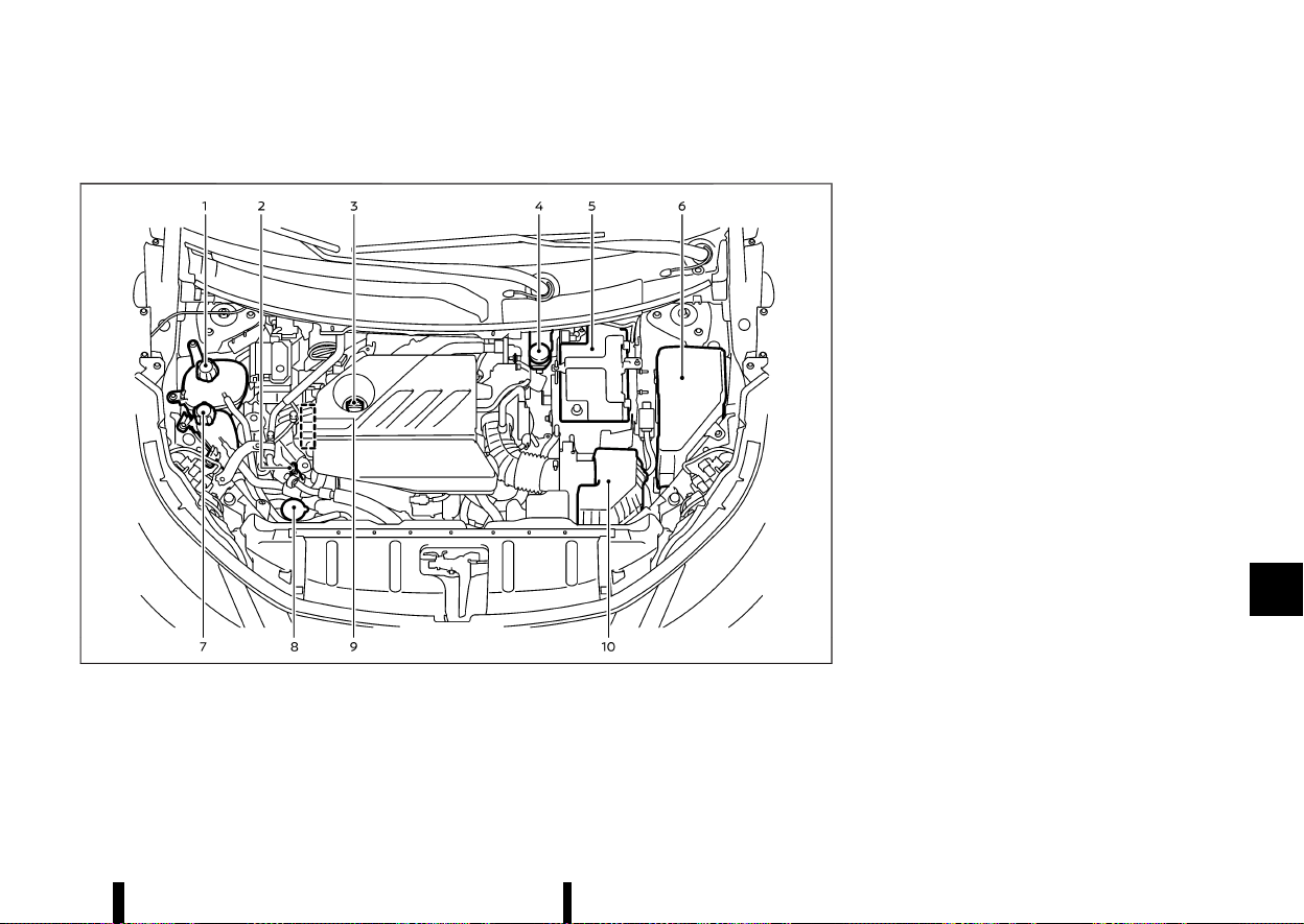
(431,1)
MEVT33A1-52D20AC3-A347-47EB-8DEB-EF2418D9025E
KR15DDT ENGINE MODEL
MEVT33A1-D4E56D47-3D72-4158-9C59-CAB9C37245E7
MWAA0443X
1. Engine coolant reservoir
2. Engine oil dipstick
3. Engine oil filler cap
4. Brake fluid reservoir*
5. Battery
6. Fuse/fusible link box
7. Intercooler coolant reservoir
8. Window washer fluid reservoir
9. Drive belt
10. Air cleaner
*: The layout illustrated is for the Left-Hand Drive
(LHD) models. On the Right-Hand Drive (RHD)
models, the brake fluid reservoir is located on the
opposite side.
Maintenance and do-it-yourself 427
ENGINE COMPARTMENT CHECK LOCATIONS
ENGINE COMPARTMENT CHECK LOCATIONS
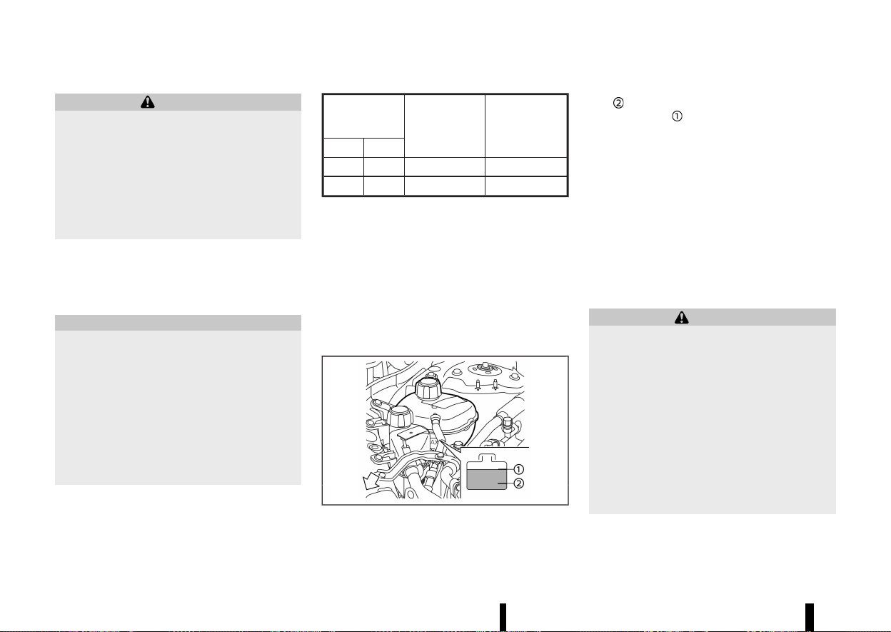
(432,1)
428 Maintenance and do-it-yourself
MEVT33A1-82EDD85D-A53D-435A-8656-F2DC3F710526
WARNING
* Never remove the radiator or the engine
coolant reservoir cap when the engine is
hot. Serious burns could be caused by
high-pressure fluid escaping from the
radiator. Wait until the engine and radiator
cool down.
* Engine coolant is poisonous and should be
stored carefully in marked containers out
of the reach of children.
The engine cooling system is filled at the factory
with a high-quality, year-round, anti-freeze coolant
solution. The anti-freeze solution contains rust and
corrosion inhibitors, therefore additional cooling
system additives are not necessary.
CAUTION
* Never use any cooling system additives
such as radiator sealer. Additives may clog
the cooling system and cause damage to
the engine, transmission and/or cooling
system.
* When adding or replacing coolant, be sure
to use only Genuine NISSAN Engine Coolant
or equivalent in its quality with the proper
mixture ratio. Examples of the mixture
ratio of coolant and water are shown in
the following table:
Outside tem-
perature down
to
Engine coolant
(concentrated)
Demineralised
or distilled
water
°C
°F
−15 5 30%
70%
−35 −30 50%
50%
Use Genuine NISSAN Engine Coolant or equivalent
in its quality. Genuine NISSAN Engine Coolant is a
pre-mixed (mixture ratio 50%) type coolant.
The use of other types of coolant solutions may
damage the engine cooling system.
The radiator is equipped with a pressure cap. To
prevent engine damage, use only a Genuine
NISSAN radiator cap or its equivalent when repla-
cement is required.
CHECKING ENGINE COOLANT LEVEL
MEVT33A1-612F80D4-E26B-4B93-AC08-C2B3435F2A37
MWAI0274X
Check the coolant level in the reservoir when the
engine is cold. If the coolant level is below the MIN
level
, open the reservoir cap and add coolant up
to the MAX level
.
Tighten the cap securely after adding engine
coolant.
If the cooling system frequently requires cool-
ant, have it checked. It is recommended you visit
a NISSAN dealer or qualified workshop for this
service.
CHANGING ENGINE COOLANT
MEVT33A1-14046F06-B9D2-494E-86AE-EBEDB6F75409
A NISSAN dealer or qualified workshop can change
the engine coolant. The service procedure can be
found in the NISSAN Service Manual.
Improper servicing can result in reduced heater
performance and engine overheating.
WARNING
* To avoid being scalded, never change the
coolant when the engine is hot.
* Never remove the radiator or coolant
reservoir cap when the engine is hot.
Serious burns could be caused by high
pressure fluid escaping from the coolant
reservoir.
* Avoid direct skin contact with used cool-
ant. If skin contact is made, wash thor-
oughly with soap or hand cleaner as soon
as possible.
* Keep coolant out of the reach of children
and pets.
Engine coolant must be disposed of properly.
Check your local regulations.
ENGINE COOLING SYSTEM
ENGINE COOLING SYSTEM
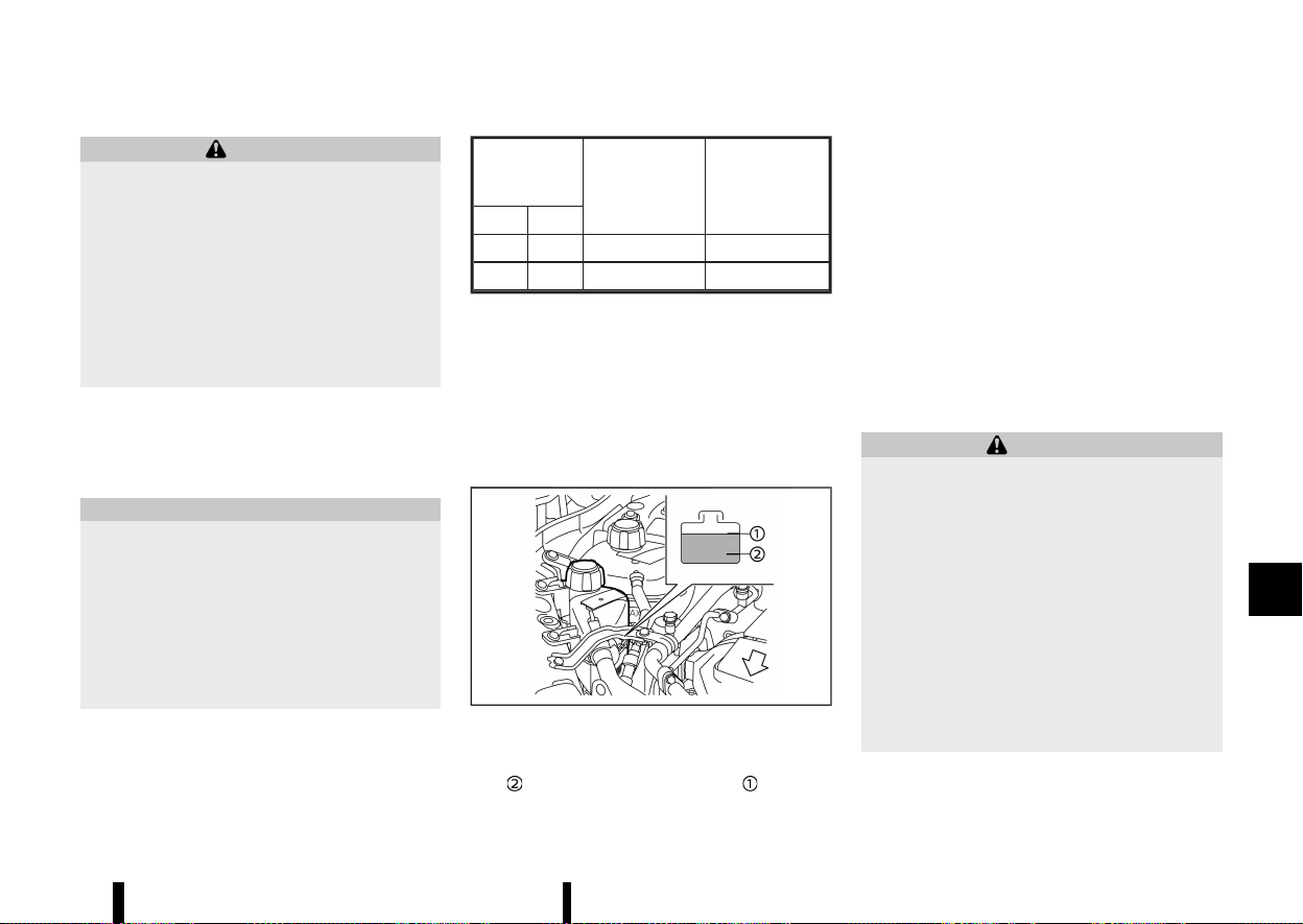
(433,1)
MEVT33A1-C83D91F5-77B4-4E82-88E7-E3F50D38635D
WARNING
* Never remove the radiator or coolant
reservoir cap when the engine is hot. Wait
until the engine cools down. Serious burns
could be caused by high pressure fluid
escaping from the radiator or coolant
reservoir.
* The coolant reservoir is equipped with a
pressure type coolant reservoir cap. To
prevent engine and intercooler damage,
use only a genuine NISSAN coolant reser-
voir cap.
The intercooler cooling system is filled at the
factory with a high-quality, year-round, anti-freeze
coolant solution. The anti-freeze solution contains
rust and corrosion inhibitors, therefore additional
cooling system additives are not necessary.
CAUTION
* Never use any additives in the coolant such
as radiator sealer in the cooling system.
This may cause damage to the intercooler.
* When adding or replacing coolant, be sure
to use only Genuine NISSAN Engine Coolant
or equivalent in its quality with the proper
mixture ratio. Examples of the mixture
ratio of coolant and water are shown in
the following tables:
Outside
temperature
down to
Coolant
(concentrated)
Demineralised or
distilled water
°C
°F
−15 5 30%
70%
−35 −30 50%
50%
The use of other types of coolant solutions may
damage the intercooler cooling system.
The intercooler reservoir is equipped with a
pressure cap. To prevent engine damage, use only
a Genuine NISSAN intercooler reservoir cap or its
equivalent when replacement is required.
CHECKING INTERCOOLER COOLANT
LEVEL
MEVT33A1-86DAC853-DAC3-4394-9644-33587E7A92E9
MWAI0261X
Check the coolant level in the reservoir when the
engine is cold. If the coolant level is below the MIN
level
, add coolant to the MAX level .
Tighten the cap securely after adding intercooler
coolant.
If the intercooler cooling system frequently
requires coolant, have it checked. It is recom-
mended you visit a NISSAN dealer or qualified
workshop for this service.
CHANGING INTERCOOLER COOLANT
MEVT33A1-C93C8B2B-B040-47BE-8825-6A6A60C8FD43
Intercooler coolant is maintenance-free.
If replacement is required, it is recommended you
visit a NISSAN dealer or qualified workshop for this
service.
Improper servicing can result in intercooler
overheating.
WARNING
* To avoid the danger of being scalded,
never change the coolant when the engine
is hot.
* Never remove the radiator or coolant
reservoir cap when the engine is hot.
Serious burns could be caused by high
pressure fluid escaping from the radiator
or coolant reservoir.
* Avoid direct skin contact with used cool-
ant. If skin contact is made, wash thor-
oughly with soap or hand cleaner as soon
as possible.
* Keep coolant out of the reach of children
and pets.
Intercooler coolant must be disposed of properly.
Check your local regulations.
Maintenance and do-it-yourself 429
INTERCOOLER COOLING SYSTEM
INTERCOOLER COOLING SYSTEM
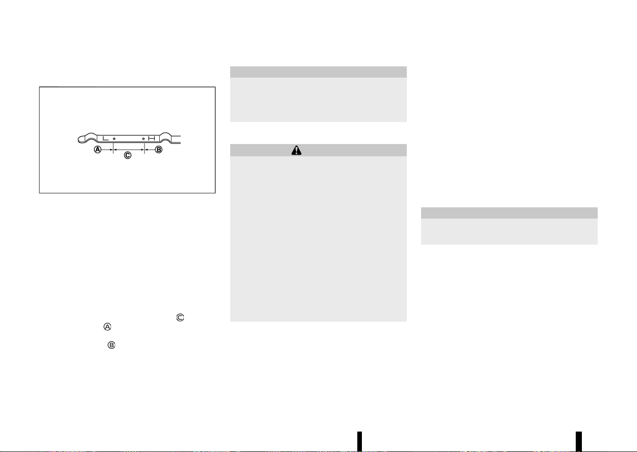
(434,1)
430 Maintenance and do-it-yourself
MEVT33A1-F50C9ACC-24A4-47A7-B339-C4E866AF09E4
CHECKING ENGINE OIL LEVEL
MEVT33A1-C7FE066F-37F5-4EF6-866F-743A4D5CA8D6
MSDI1993
1. Park the vehicle on a level surface and apply
the parking brake.
2. Run the engine until it reaches operating
temperature.
3. Turn off the engine. Wait more than 10
minutes for the oil to drain back into the oil
pan.
4. Remove the dipstick and wipe it clean. Reinsert
it all the way.
5. Remove the dipstick again and check the oil
level. It should be within the range
. If the oil
level is below
, remove the oil filler cap and
pour recommended oil through the opening.
Do not overfill
.
6. Recheck oil level with the dipstick.
It is normal to add some oil between oil main-
tenance intervals or during the running-in per-
iod, depending on the severity of operating
conditions.
CAUTION
Oil level should be checked regularly. Operat-
ing the engine with an insufficient amount of
oil can damage the engine, and such damage
is not covered by the warranty.
CHANGING ENGINE OIL AND FILTER
MEVT33A1-1429280C-2164-4979-AB59-A82BBA48D3F2
WARNING
* Used oil must be disposed of properly.
Never pour or dump oil into the ground,
canals, rivers, etc. It should be disposed of
at proper waste facilities. NISSAN recom-
mends having your oil changed by a
NISSAN dealer or qualified workshop.
* Be careful not to burn yourself, as the
engine oil may be hot.
* Prolonged and repeated contact with used
engine oil may cause skin cancer.
* Avoid direct skin contact with used oil. If
contacted, wash thoroughly with soap or
hand cleaner and plenty of water as soon
as possible.
* Store used engine oil in marked containers
out of the reach of children.
Vehicle set-up
MEVT33A1-D33812FA-0489-4509-B0E6-6388A81BEBEA
1. Park the vehicle on a level surface and apply
the parking brake.
2. Run the engine until it reaches the operating
temperature.
3. Turn the engine off and wait more than 10
minutes.
4. Raise and support the vehicle using a suitable
floor jack and safety jack stands.
.
Place the safety jack stands under the
vehicle jack-up points.
.
A suitable adapter should be attached to
the jack stand saddle.
5. Remove the engine undercover.
.
Remove clips at the around of the under-
cover.
.
Then remove the other bolts that hold the
undercover in place.
CAUTION
Make sure the correct lifting and support
points are used to avoid vehicle damage.
ENGINE OIL
ENGINE OIL
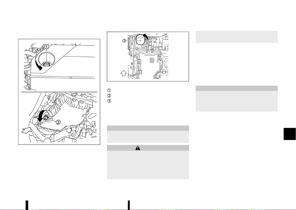
(435,1)
Engine oil and filter
MEVT33A1-0E3F5EC9-066C-4F79-BDC5-1BCF07F45F7E
MWAI0292X
MWAI0263X
Oil filler cap
Oil drain plug
Oil filter
1. Place a large drain pan under the drain plug.
2. Remove the oil filler cap.
3. Remove the drain plug with a wrench and
completely drain the oil.
CAUTION
Be careful not to burn yourself, as the engine
oil is hot.
WARNING
* Prolonged and repeated contact with used
engine oil may cause skin cancer.
* Try to avoid direct skin contact with used
oil. If skin contact is made, wash thor-
oughly with soap or hand cleaner as soon
as possible.
* Keep used engine oil out of reach of
children.
.
Waste oil must be disposed of properly.
.
Check your local regulations.
(Perform steps 4 to 7 only when the engine oil
filter change is needed.)
4. Loosen the oil filter with an oil filter wrench.
Remove the oil filter by turning it by hand.
5. Wipe the engine oil filter mounting surface
with a clean rag.
CAUTION
Be sure to remove any old gasket material
remaining on the mounting surface of the
engine. Failure to do so could lead to engine
damage.
6. Coat the gasket on the new filter with clean
engine oil.
7. Screw in the oil filter clockwise until a slight
resistance is felt, then tighten additionally
more than 2/3 turn.
Oil filter tightening torque:
15.0 to 21.0 N·m
(1.5 to 2.1 kg-m, 11 to 15 ft-lb)
8. Clean and re-install the drain plug with a new
washer. Securely tighten the drain plug with a
wrench.
Drain plug tightening torque:
30.0 to 37.0 N·m
(3.1 to 3.8 kg-m, 22 to 27 ft-lb)
Maintenance and do-it-yourself 431
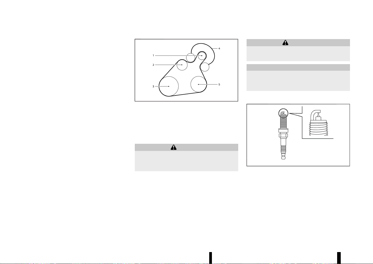
(436,1)
432 Maintenance and do-it-yourself
Do not use excessive force.
9. Refill the engine with the recommended oil
through the oil filler opening, and install the oil
filler cap securely.
See “Recommended fluids/lubricants and ca-
pacities” (P.456) for drain and refill capacity.
The drain and refill capacity depends on the oil
temperature and drain time. Use these speci-
fications for reference only. Always use the
dipstick to determine the proper amount of oil
in the engine.
10. Start the engine and check for leakage around
the drain plug and the oil filter. Correct as
required.
11. Turn the engine off and wait more than 10
minutes. Check the oil level with the dipstick.
Add engine oil if necessary.
After the operation
MEVT33A1-02E3EFF4-6A0C-4167-AC8B-E5E800B03EDA
1. Reinstall undercover in reverse order of re-
moval.
2. Lower the vehicle carefully to the ground.
3. Reset the Oil Control System and oil and filter
maintenance reminder. (See “[Maintenance]”
(P.88).)
MEVT33A1-1AF74337-E578-4C98-A7ED-F2206E4170AC
MWAI0293X
1. Starter generator
2. Water pump
3. Crankshaft pulley
4. Drive belt auto-tensioner
5. Air conditioner compressor
WARNING
Be sure the ignition switch is in the “OFF”
position before servicing drive belts. The en-
gine could rotate unexpectedly.
1. Visually inspect the belt for signs of unusual
wear, cuts or fraying. If the belt is in poor
condition, have it replaced. It is recommended
that you visit a NISSAN dealer or qualified
workshop for this service.
2. Have the belt condition checked regularly.
MEVT33A1-AAF18895-92AC-4601-BD68-201C81BA060E
WARNING
Be sure the engine and ignition switch are off
and that the parking brake is applied.
CAUTION
Be sure to use the correct socket to remove the
spark plugs. An incorrect socket can damage
the spark plugs.
REPLACING SPARK PLUGS
MEVT33A1-C62B4C9C-0259-481F-A5AB-DFBBB3D10B69
MSDI2670
If replacement is required, it is recommended you
visit a NISSAN dealer or qualified workshop for this
service.
Iridium platinum-tipped spark plugs
MEVT33A1-E12E20CD-D386-439E-A361-43DA33D9C4A6
It is not necessary to replace the iridium platinum-
tipped spark plugs as frequently as the conven-
tional type spark plugs since they will last much
longer. Follow the maintenance schedule shown in
a separate maintenance booklet. Do not reuse the
DRIVE BELT
DRIVE BELT
SPARK PLUGS
SPARK PLUGS
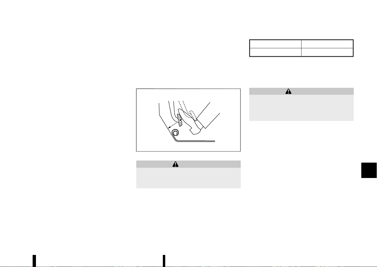
(437,1)
iridium platinum-tipped spark plugs by cleaning or
regapping.
Always replace spark plugs with recommended
or equivalent ones.
MEVT33A1-2B31454F-BCAF-420F-B285-264881F399AA
CHECKING PARKING BRAKE
MEVT33A1-60A0F4F8-0626-4AA0-9BB6-72E11A06C6FF
Periodically check the holding ability of the parking
brake by parking on a steep hill and restraining the
vehicle by using only the parking brake. If it does
not hold satisfactorily, see a NISSAN dealer or
qualified workshop.
CHECKING FOOTBRAKE
MEVT33A1-31B30D0A-96B6-4CD5-9E50-FF14DDD047A0
MDI1020MM
WARNING
See a NISSAN dealer or qualified workshop for
a brake system check if the brake pedal height
does not return to normal.
With the engine running, check the distance
between the upper surface of the pedal and the
metal floor. If it is out the range listed, see a NISSAN
dealer or qualified workshop.
Depressing force
490 N (50 kg, 110 lb)
LHD model
RHD model
75 mm (3.0 in) or more
90 mm (3.5 in) or more
Self-adjusting brakes
MEVT33A1-28B8AA7E-6AD4-49DC-A969-9DE078A1FF1E
Your vehicle is equipped with self-adjusting brakes.
The disc-type brakes self-adjust every time the
brake pedal is applied.
WARNING
Have your brake system checked if the brake
pedal height does not return to normal. It is
recommended you visit a NISSAN dealer or
qualified workshop for this service.
Brake pad wear warning
MEVT33A1-55019B81-BB33-4B67-AE42-95680A304881
The disc brake pads have audible wear warnings.
When a brake pad requires replacement, it will
make a high pitched scraping sound when the
vehicle is in motion. This scraping sound will first
occur only when the brake pedal is depressed.
After more wear of the brake pad, the sound will
always be heard even if the brake pedal is not
depressed. Have the brakes checked as soon as
possible if the wear warning sound is heard.
Under some driving or climate conditions, occa-
sional brake squeaks, squeals or other noises may
be heard. Occasional brake noise during light to
moderate stops is normal and does not affect the
function or performance of the brake system.
Proper brake inspection intervals should be fol-
lowed. For additional information, see a separate
maintenance booklet.
Maintenance and do-it-yourself 433
BRAKES
BRAKES
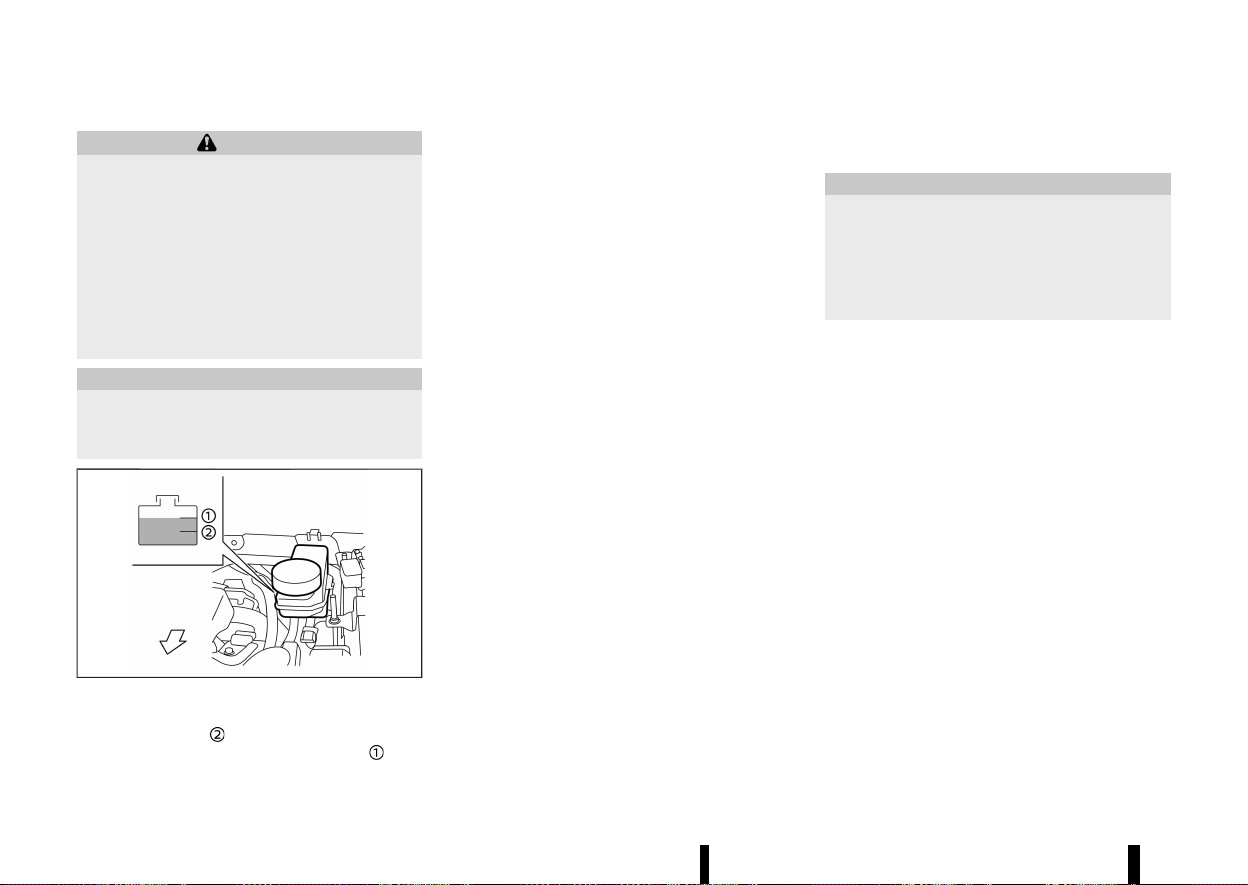
(438,1)
434 Maintenance and do-it-yourself
MEVT33A1-87A23E55-51A4-4EED-AB77-41D829C099F9
WARNING
* Use only new fluid from a sealed container.
Old, inferior, or contaminated fluid may
damage the brake system. The use of
improper fluids can damage the brake
system and affect the vehicle’s stopping
ability.
* Clean the filler cap before removing.
* Brake fluid is poisonous and should be
stored carefully in marked containers out
of the reach of children.
CAUTION
Do not spill the fluid on painted surfaces. This
will damage the paint. If fluid is spilled, wash it
off with plenty of water immediately.
MWAI0186X
Check the fluid level in the reservoir. If the fluid is
below the MIN line
, the brake warning light will
illuminate. Add fluid up to the MAX line
. (See
“Recommended fluids/lubricants and capacities”
(P.456) for recommended types of fluid.)
If the fluid must be added frequently, the system
should be thoroughly checked by a NISSAN dealer
or qualified workshop.
Replace the brake fluid according to the main-
tenance log shown in a separate maintenance
booklet.
MEVT33A1-493B42A6-9A7A-45D2-8DCD-565E3D1E9BF5
Contact a NISSAN dealer or qualified workshop if
checking or replacement is required.
CAUTION
* Use only Genuine NISSAN CVT Fluid NS-3.
Do not mix with other fluids.
* Using transmission fluid other than Genu-
ine NISSAN CVT Fluid NS-3 may damage
the CVT, which is not covered by the
warranty.
BRAKE FLUID
BRAKE FLUID
CONTINUOUSLY VARIABLE
TRANSMISSION (CVT) FLUID
CONTINUOUSLY VARIABLE
TRANSMISSION (CVT) FLUID
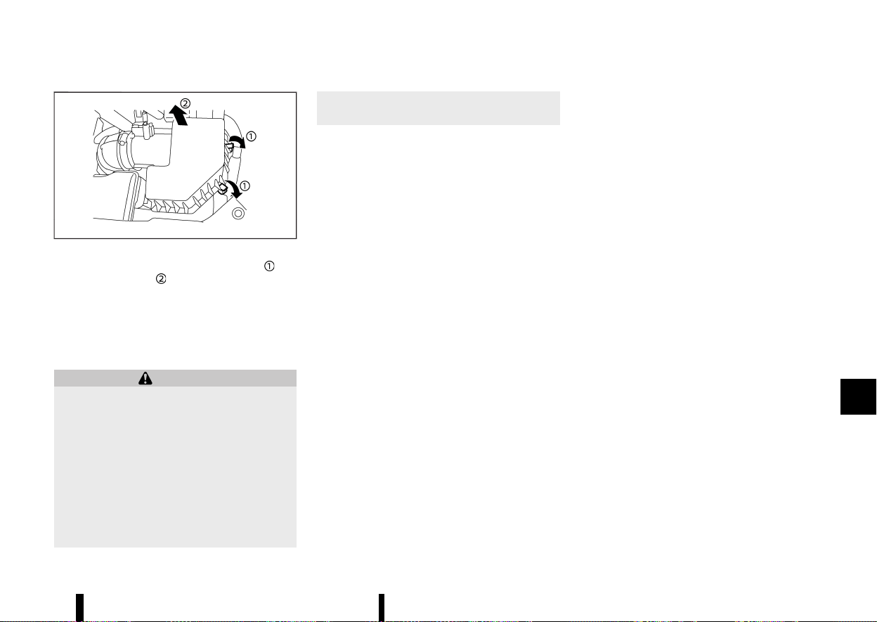
(439,1)
MEVT33A1-A7EFD3D5-8983-4D24-A2FC-51D31347536E
MWAI0160X
To remove the filter, release the lock pins and
pull the unit upward
.
The dry paper type filter element may be cleaned
and reused. Replace the filter according to the
maintenance schedule shown in a separate main-
tenance booklet. When replacing the filter, wipe
the inside of the air cleaner housing and the cover
with a damp cloth.
WARNING
* Operating the engine with the air cleaner
filter off can cause you or others to be
burned. The air cleaner filter not only
cleans the intake air, it also stops flame if
the engine backfires. If the air cleaner filter
is not installed and the engine backfires,
you could be burned. Never drive with the
air cleaner filter off. Be cautious working
on the engine when the air cleaner filter is
off.
* Never pour fuel into the throttle body or
attempt to start the engine with the air
cleaner removed. Doing so could result in
serious injury.
Maintenance and do-it-yourself 435
AIR CLEANER
AIR CLEANER
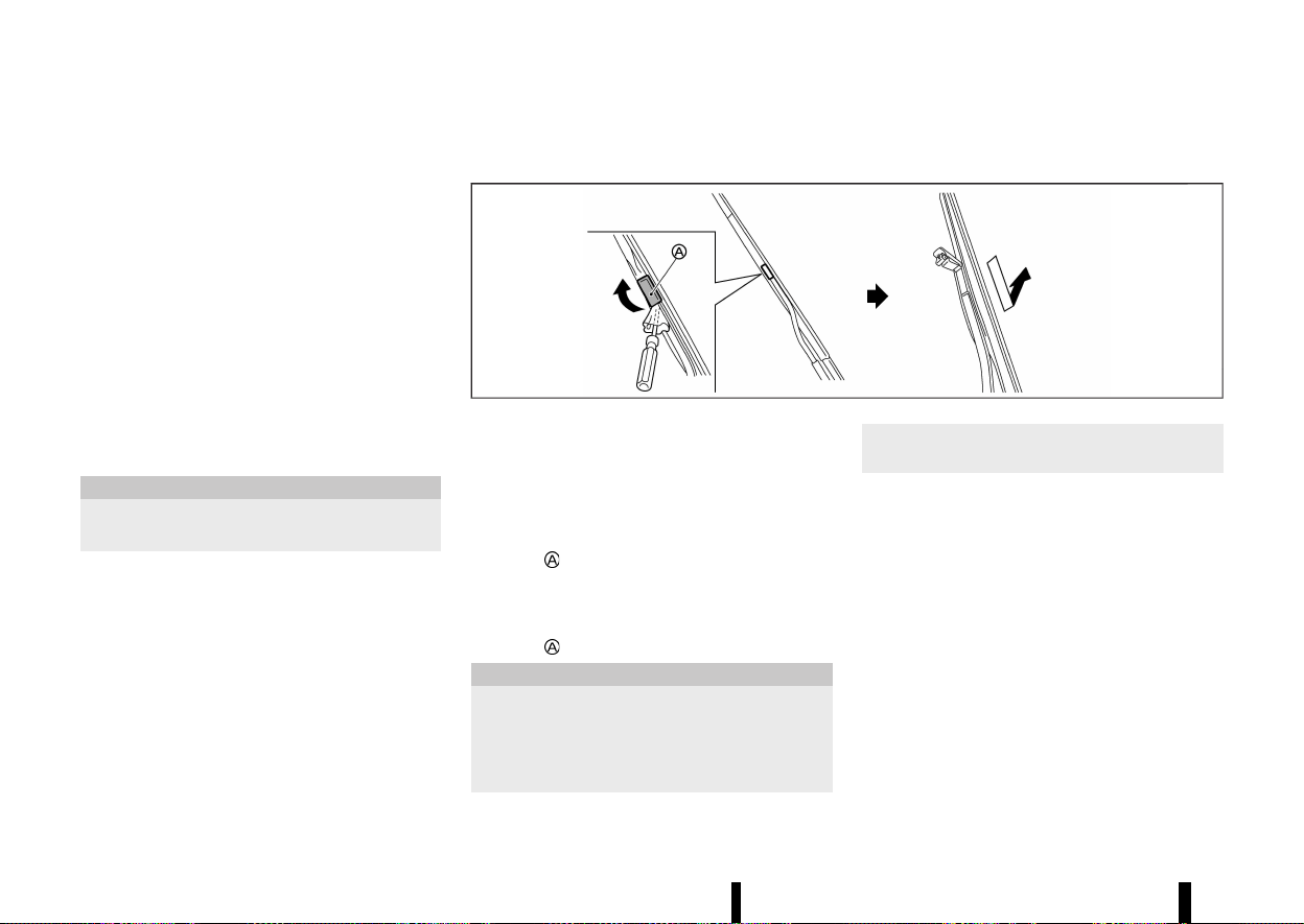
(440,1)
436 Maintenance and do-it-yourself
MEVT33A1-5D3853F1-457C-43BF-BB0B-081E44A4FA78
WINDSCREEN WIPER BLADES
MEVT33A1-9EDC6DE3-BF19-4583-99BA-EB1D41228F66
Cleaning
MEVT33A1-49071CBE-D68E-45DF-B0FB-4E24EC69E48E
If your windscreen is not clear after using the
windscreen washer or if a wiper blade chatters
when running, wax or other material may be on
the blade or windscreen.
Clean the outside of the windscreen with a washer
solution or a mild detergent. Your windscreen is
clean if beads do not form when rinsing with clear
water.
Clean each blade by wiping it with a cloth soaked
in a washer solution or a mild detergent. Then
rinse the blade with clear water. If your windscreen
is still not clear after cleaning the blades and using
the wiper, replace the blades.
CAUTION
Worn windscreen wiper blades can damage
the windscreen and impair driver vision.
When a washer nozzle is clogged:
It is recommended you see a NISSAN dealer or
qualified workshop if a washer nozzle is clogged or
any malfunction occurs. Do not attempt to clean
the nozzle using a needle or a pin. Doing so may
damage the nozzle.
Replacing
MEVT33A1-3AFC67FF-FD24-43FF-A0BD-093F6A3B2436
MWAI0163X
Replace the wiper blades if they are worn.
1. Lift the wiper arm away from the windscreen.
When lifting the wiper arm, lift the driver’s
side first, then the passenger’s side. Other-
wise, the wiper blades may be scratched and
may cause damage.
2. Open
, using a suitable tool, and then move
the wiper blade down as shown to remove.
3. Insert the new wiper blade onto the wiper arm
until a click sounds.
4. Close
.
CAUTION
* After wiper blade replacement, return the
wiper arm to its original position; other-
wise it may be damaged when the bonnet
is opened.
* Make sure the wiper blades contact the
glass; otherwise the arm may be damaged
from wind pressure.
REAR WINDOW WIPER BLADE
MEVT33A1-4FE910FB-E99A-42DF-B107-5DBED177B1BD
It is recommended you contact a NISSAN dealer or
qualified workshop if checking or replacement is
required.
WIPER BLADES
WIPER BLADES
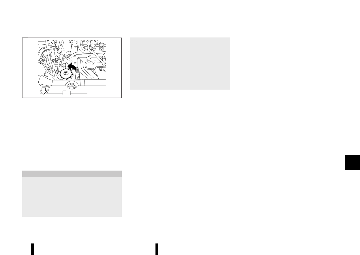
(441,1)
MEVT33A1-5D2D6CB1-F8DE-4118-AB39-2159D4185FFF
MWAI0267X
Check the fluid level in the window washer
reservoir. If the fluid level is low, add window
washer fluid.
Add a washer solvent to the washer for better
cleaning. In the winter season, add a windscreen
washer antifreeze. Follow the manufacturer’s in-
structions for the mixture ratio.
Fill the window washer fluid reservoir periodically.
Refill the reservoir more frequently when driving
conditions require an increased amount of win-
dow washer fluid.
CAUTION
* Do not substitute engine anti-freeze cool-
ant for window washer solution. This may
result in damage to the paint.
* Do not fill the window washer reservoir
tank with washer fluid concentrates at full
strength. Some methyl alcohol based
washer fluid concentrates may perma-
nently stain the grille if spilled while filling
the window washer reservoir tank.
* Pre-mix washer fluid concentrates with
water to the manufacturer’s recom-
mended levels before pouring the fluid
into the window washer reservoir tank.
Do not use the window washer reservoir
tank to mix the washer fluid concentrate
and water.
MEVT33A1-B29BEC73-37B3-4C87-9A9D-EA809C865599
VEHICLE BATTERY
MEVT33A1-F08426CA-9ABA-4800-BE91-9B580428D6D3
Maintenance and do-it-yourself 437
WINDOW WASHER FLUID
WINDOW WASHER FLUID
BATTERY
BATTERY
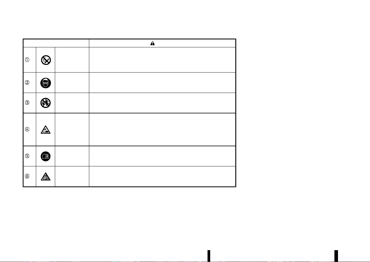
(442,1)
438 Maintenance and do-it-yourself
Caution symbols for battery
WARNING
No smoking
No exposed
flames
No sparks
Never smoke around the battery. Never expose the battery to open flames
or electrical sparks.
Shield eyes
Handle the battery cautiously. Always wear eye protection glasses to protect
against explosion or battery acid.
Keep away from
children
Never allow children to handle the battery. Keep the battery out of reach of
children.
Battery acid
Do not allow battery fluid to contact your skin, eyes, fabrics, or painted
surfaces. After handling the battery or battery cap, immediately wash your
hands thoroughly. If the battery fluid gets into your eyes, or onto your skin or
clothing, flush with water immediately for at least 15 minutes and seek
medical attention. Battery fluid is acid. If the battery fluid gets into your eyes
or onto your skin, it could cause eyesight loss or burns.
Note operating
instructions
Before handling the battery, read this instruction carefully to ensure correct
and safe handling.
Explosive gas
Hydrogen gas, generated by battery fluid, is explosive.
Main battery (12-volt battery)
MEVT33A1-04A7302E-A469-4DAE-834B-6691460E97F9
See “Engine compartment check locations” (P.427)
for the battery location.
* If the battery is labeled “do not open” it is
maintenance free and battery fluid should not
be checked. It is recommended that you visit a
NISSAN dealer or qualified workshop or a
qualified specialist workshop to confirm the
battery’s performance.
* Keep the battery surface clean and dry. Clean
the battery with a solution of baking soda and
water.
* Make certain the terminal connections are
clean and securely tightened.
* If the vehicle is not to be used for 30 days or
longer, disconnect the negative 7 battery
terminal cable to prevent discharging it.
NOTE:
Care should be taken to avoid situations that
can lead to potential battery discharge and
potential no-start conditions such as:
1. Installation or extended use of electronic
accessories that consume battery power
when the engine is not running (Phone
chargers, GPS, DVD players, etc.).
2. Vehicle is not driven regularly and/or only
driven short distances.
In these cases, the battery may need to be
charged to maintain battery health.
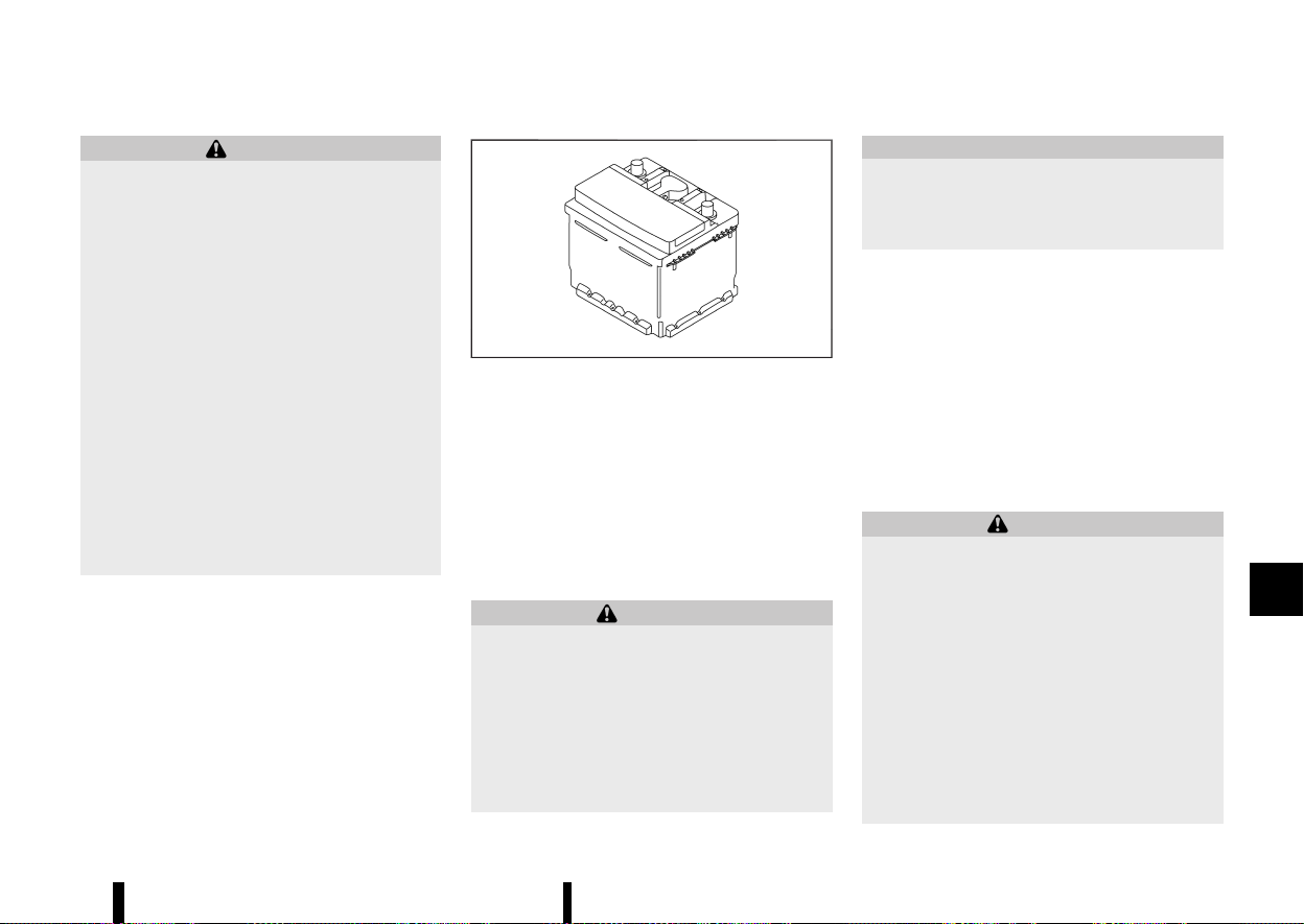
(443,1)
WARNING
* Do not expose the battery to flames or
electrical sparks. Hydrogen gas generated
by the battery is explosive. Do not allow
battery fluid to contact your skin, eyes,
fabrics or painted surfaces. After touching
a battery or battery cap, do not touch or
rub your eyes. Thoroughly wash your
hands. If the acid contacts your eyes, skin
or clothing, immediately flush with water
for at least 15 minutes and seek medical
attention.
* When working on or near a battery, always
wear suitable eye protection and remove
all jewellery.
* Battery posts, terminals and related ac-
cessories contain lead and lead com-
pounds. Wash hands after handling.
* Keep the battery out of the reach of
children.
* Do not tip the battery.
MWAI0200X
Example
NOTE:
Do not try to open the top of the battery.
This battery is not equipped with removable vent
caps.
Auxiliary battery (Lithium ion battery)
MEVT33A1-525B4C9E-D315-4F88-BAE7-D9451853136C
The Lithium ion (Li-ion) battery is located under the
front passenger’s seat.
Precautions on the Li-ion battery:
WARNING
* Do not let the Li-ion battery get wet.
* Do not remove or disassemble the Li-ion
battery.
* Do not subject the Li-ion battery to impact.
* Do not remove the Li-ion battery terminal
or connect any electrical equipment to the
terminal.
* Do not put fire close to the Li-ion battery.
CAUTION
Do not place any heavy objects under the front
seat or stomp the floor around there, as the Li-
ion battery is located under the front passen-
ger’s seat.
When starting or stopping the engine, sound may
be heard from under the front passenger’s seat.
This is an operating sound of the Li-ion battery
and does not indicate a malfunction.
JUMP STARTING
MEVT33A1-C37C3C0F-280C-4F1D-904A-46ACD5752008
If jump starting is necessary, see “Jump starting”
(P.409). If the engine does not start by jump
starting, the battery may have to be replaced. It
is recommended you visit a NISSAN dealer or
qualified workshop for this service.
INTELLIGENT KEY BATTERY
MEVT33A1-E03C12AE-5204-44DA-8C92-75FB6768F780
WARNING
Do not ingest the battery, Chemical Burn
Hazard
This product contains a coin/button cell bat-
tery. If the coin/button cell battery is swal-
lowed, it can cause severe internal burns in just
2 hours and can lead to death.
Keep new and used batteries away from
children. If the battery compartment does not
close securely, stop using the product and
keep it away from children.
If you think batteries might have been swal-
lowed or placed inside any part of the body,
seek immediate medical attention.
Maintenance and do-it-yourself 439
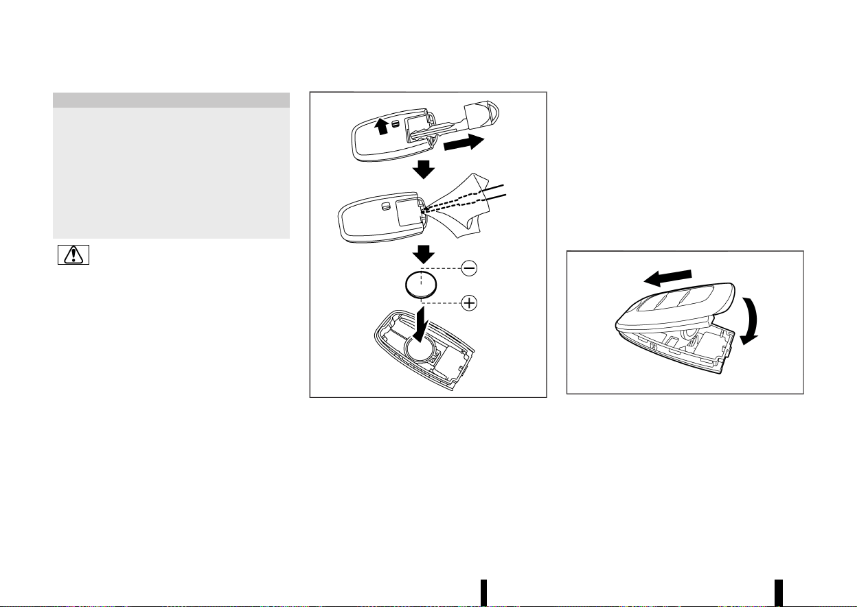
(444,1)
440 Maintenance and do-it-yourself
CAUTION
* Danger of explosion if battery is incorrectly
replaced. Replace only with the same or
equivalent type.
* Do not exposed to excessive heat such as
sunshine, fire or the like.
* Do not give mechanically crushing or cut-
ting of a battery.
* Do not subjected to extremely low air
pressure at high altitude.
This symbol is intended to alert the user to
the presence of important operating and
maintenance (servicing) instructions in the
literature accompanying the appliance.
MWBI0014X
Replace the battery in the Intelligent Key as
follows:
1. Remove the mechanical key from the Intelli-
gent Key.
2. Insert a small screwdriver into the slit of the
corner and twist it to separate the upper part
from the lower part. Use a cloth to protect the
casing.
3. Replace the battery with a new one.
Recommended battery:
CR2032 or equivalent
.
Do not touch the internal circuit and electric
terminals as doing so could cause a mal-
function.
.
Hold the battery by the edges. Holding the
battery across the contact points will ser-
iously deplete the storage capacity.
.
Make sure that the + side faces the bottom
of the case.
MWBI0015X
4. Align the tips of the upper and lower parts, and
then push them together until it is securely
closed.
5. Operate the buttons to check its operation.
If you need any assistance for replacement, it is
recommended you visit a NISSAN dealer or quali-
fied workshop for this service.
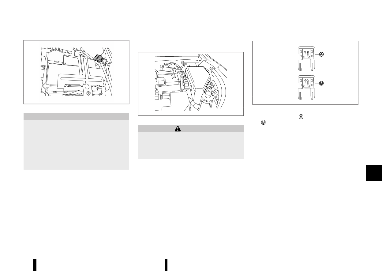
(445,1)
MEVT33A1-0A40E5F3-EC90-4F03-B955-4274A23D7967
MWAI0223X
CAUTION
* Do not ground accessories directly to the
battery terminal. Doing so will bypass the
variable voltage control system and the
vehicle battery may not charge comple-
tely.
* Use electrical accessories with the engine
running to avoid discharging the vehicle
battery.
The variable voltage control system measures the
amount of electrical discharge from the battery
and controls voltage generated by the generator.
MEVT33A1-6A89546B-C41A-40D8-9756-83B8312ACE54
ENGINE COMPARTMENT
MEVT33A1-7E1E202F-F646-45EA-96AE-D77C542478CE
MWAI0124X
WARNING
Never use a fuse of a higher or lower amperage
rating than that specified on the fuse box
cover. This could damage the electrical system
or electronic control units or cause a fire.
If any electrical equipment does not operate, check
for an open fuse.
1. Be sure the ignition switch is turned off and
the headlights are off.
2. Open the engine bonnet.
3. Remove the fuse/fusible link box cover by
using a suitable tool and pushing the tab.
4. Locate the fuse that needs to be replaced.
5. Remove the fuse using the fuse puller located
in the passenger compartment fuse box.
MSDI1753
6. If the fuse is open , replace it with a new fuse
.
7. If a new fuse also opens, have the electrical
system checked and repaired. It is recom-
mended you visit a NISSAN dealer or qualified
workshop for this service.
Fusible links
MEVT33A1-0B3A4B09-B2AB-4E3F-A956-B422F7712949
If any electrical equipment does not operate and
the fuses are in good condition, check the fusible
links. If any of these fusible links are melted,
replace only with genuine NISSAN parts.
For checking and replacing the fusible links, it is
recommended you visit a NISSAN dealer or quali-
fied workshop.
Maintenance and do-it-yourself 441
VARIABLE VOLTAGE CONTROL SYSTEM
VARIABLE VOLTAGE CONTROL SYSTEM
FUSES
FUSES
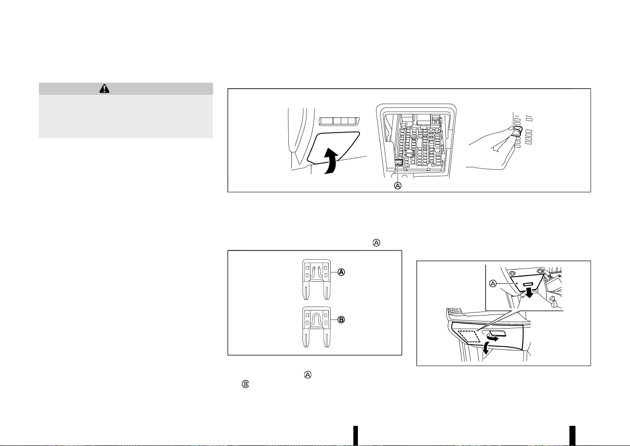
(446,1)
442 Maintenance and do-it-yourself
PASSENGER COMPARTMENT
MEVT33A1-1A5CCAAE-C01A-4D2F-AF88-DD9437C6D5CF
WARNING
Never use a fuse of a higher or lower amperage
rating than that specified on the fuse box
cover. This could damage the electrical system
or electronic control units or cause a fire.
If any electrical equipment does not operate, check
for an open fuse.
Left-Hand Drive (LHD) MODEL
MEVT33A1-3983D826-7000-45BE-9F71-6A4547203BBB
MWAI0205X
1. Be sure the ignition switch is turned off and
the headlights are off.
2. Remove the fuse box cover.
3. Remove the fuse with the fuse puller
.
MSDI1753
4. If the fuse is open , replace it with a new fuse
.
5. If a new fuse also opens, have the electrical
system checked and repaired. It is recom-
mended you visit a NISSAN dealer or qualified
workshop for this service.
Right-Hand Drive (RHD) MODEL
MEVT33A1-4B266A8A-BCC6-43D1-9C9B-9864F96CA766
MWAI0362X
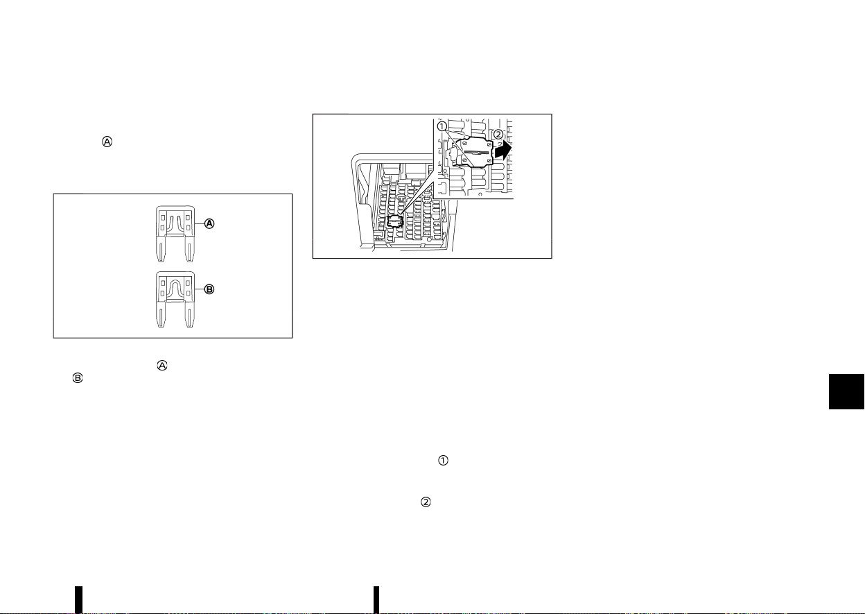
(447,1)
1. Be sure the ignition switch is turned off and
the headlights are off.
2. Open the glove box and remove the fuse box
cover
inside the glove box.
3. Remove the fuse with the fuse puller. (The fuse
puller is located as shown in the illustration for
LHD models.)
MSDI1753
4. If the fuse is open , replace it with a new fuse
.
5. If a new fuse also opens, have the electrical
system checked and repaired. It is recom-
mended you visit a NISSAN dealer or qualified
workshop for this service.
Extended storage switch (where fitted)
MEVT33A1-C466938A-8C78-4487-B709-66DC15F83749
MWAI0271X
The extended storage switch is used when ship-
ping the vehicle. It is located in the fuse panel. If
any electrical equipment does not operate, ensure
the extended storage switch is pushed fully in
place.
To inspect the extended storage switch, ensure
the ignition switch and headlights are off.
How to remove the extended storage switch:
1. To remove the extended storage switch, be
sure the ignition switch is in the “OFF” position.
2. Be sure the headlights are off.
3. Remove the fuse box cover.
4. Pinch the locking tabs
on top and bottom of
the extended storage switch.
5. Pull the extended storage switch straight out
from the fuse box
.
Maintenance and do-it-yourself 443
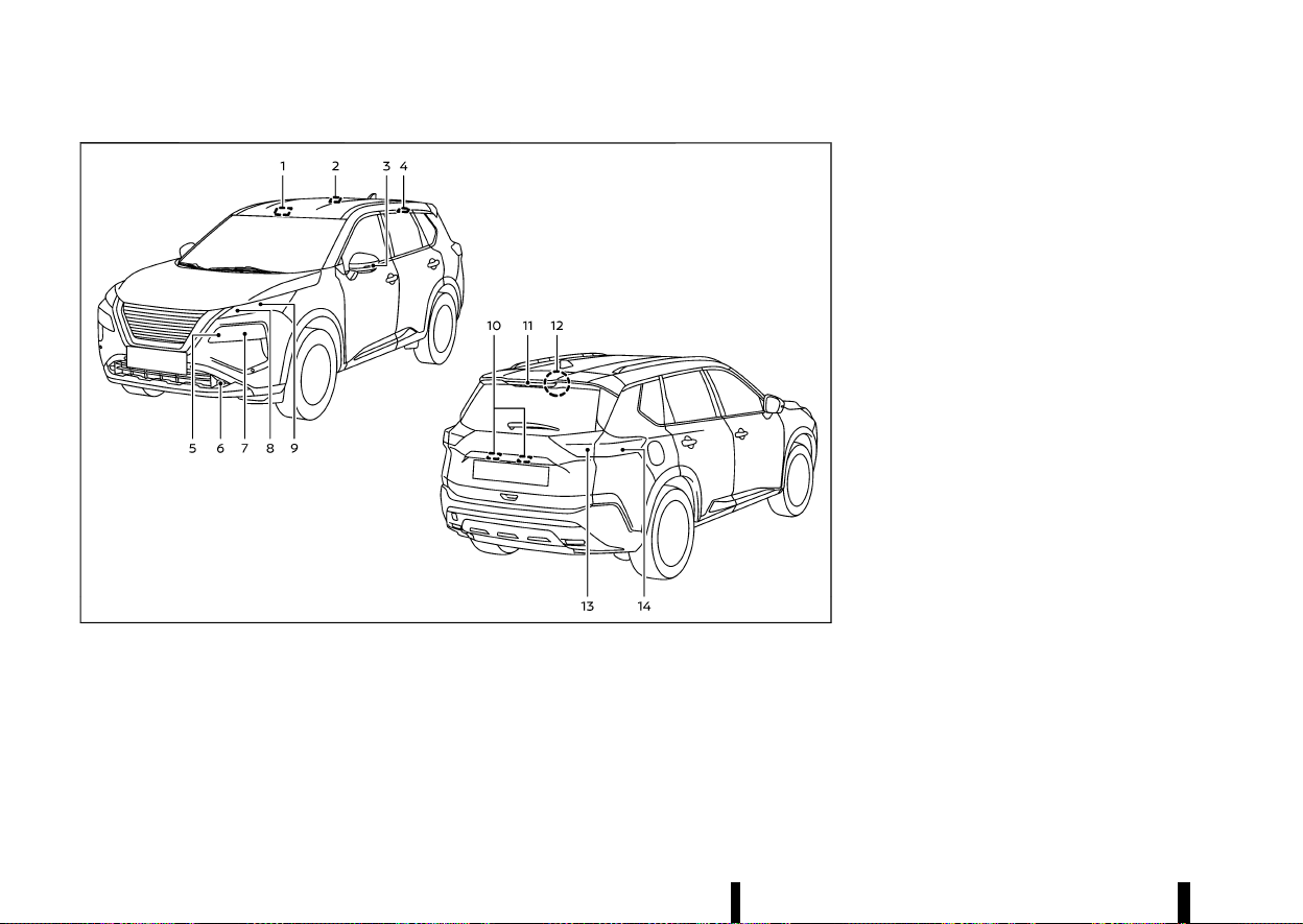
(448,1)
444 Maintenance and do-it-yourself
MEVT33A1-23FC80BC-9A5D-4CDF-AF41-4375212E36BD
MWAI0349X
1. Front map light
2. Room light (where fitted)
3. Side turn signal light
4. Rear personal light (where fitted)
5. Headlight (high-beam)
6. Front fog light (where fitted)
7. Headlight (low-beam)
8. Front clearance light/Daytime running light/
Front turn signal light (LED type)
9. Front turn signal light (Bulb type)
10. Number plate light
11. High-mounted brake light
12. Cargo light
13. Reversing light/Tail light/Rear fog light*
14. Rear turn signal light/Brake light/Tail light
*: Driver’s side only
LIGHTS
LIGHTS
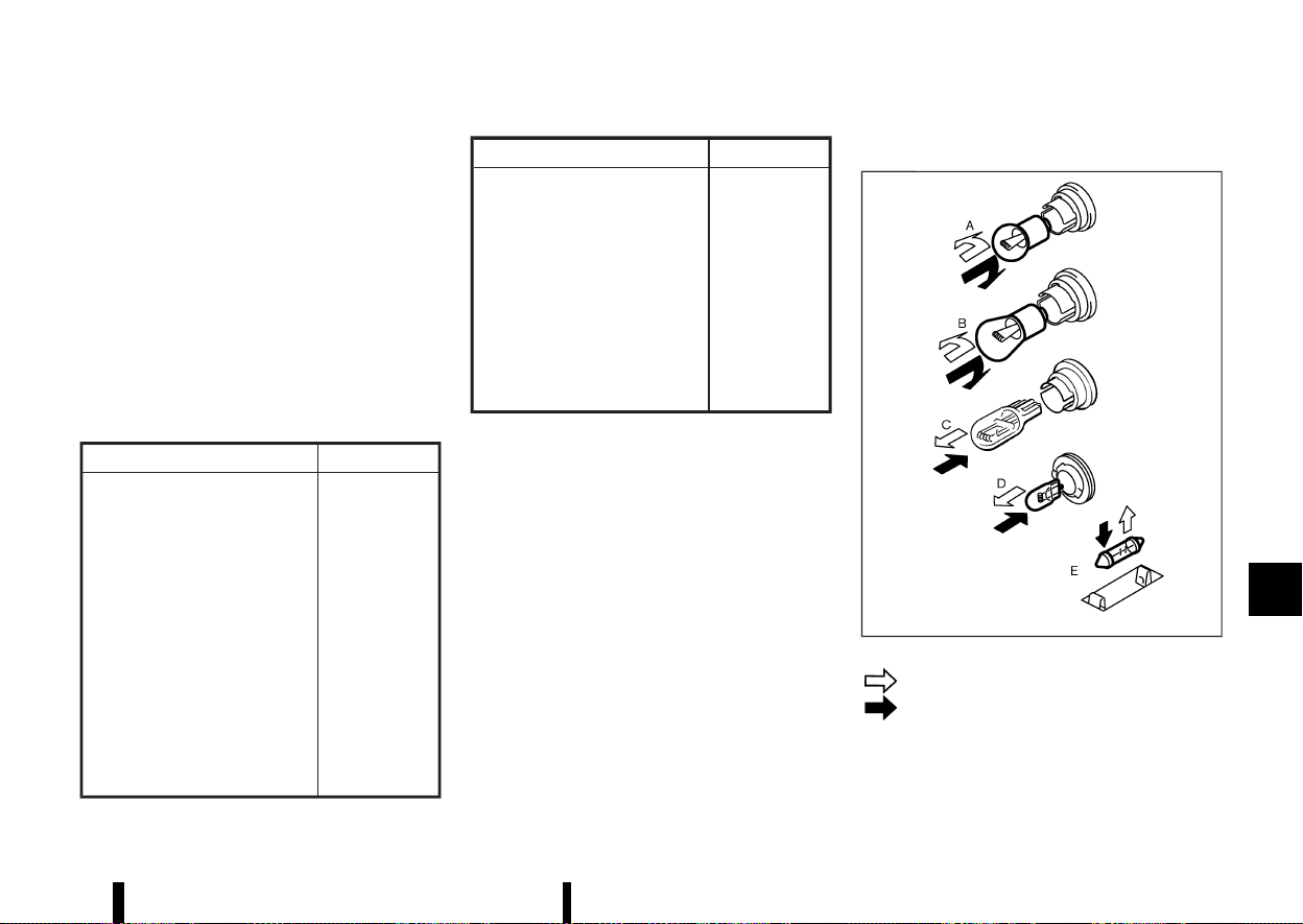
(449,1)
HEADLIGHTS
MEVT33A1-2315F15B-21C2-48E3-B4D6-114A3540E8D5
Fog may temporarily form inside the lens of the
exterior lights in the rain or in a car wash. A
temperature difference between the inside and
the outside of the lens causes the fog. This is not a
malfunction. If large drops of water collect inside
the lens, it is recommended you visit a NISSAN
dealer or qualified workshop for servicing.
Replacing
MEVT33A1-E802D82D-AE31-4C67-BD7D-36FB0F025F80
If LED headlight replacement is required, it is
recommended that you visit a NISSAN dealer or
qualified workshop for this service.
EXTERIOR AND INTERIOR LIGHTS
MEVT33A1-61BBD601-FAE2-461C-81CD-A4009E8538F6
Item Wattage (W)
Headlight high/low beams* LED
Front turn signal light* 21 or LED
Front clearance light* LED
Front fog light (where fitted)* LED
Side turn signal light* LED
Daytime running light* LED
Rear combination light*
Turn signal light 21
Brake light LED
Tail light LED
Reversing light 16
Rear fog light* LED
Item Wattage (W)
Number plate light* 5 (assembly)
Map light* 16
Rear personal light (where fitted)* 10
High-mounted brake light* LED
Room light (where fitted)* 16
Cargo light 5
Console light* 1.4 or LED
Lower centre light* 1.4 or LED
Glove box light* 1.4
*: It is recommended you visit a NISSAN dealer
or qualified workshop for replacement.
Replacement procedures
MEVT33A1-FD1940F8-D0CC-49B0-9D9B-69150AD59693
MSDI2306
: REMOVE
: INSTALL
All other lights are either type A, B, C, D or E. When
replacing a bulb, first remove the lens and/or
cover.
Maintenance and do-it-yourself 445
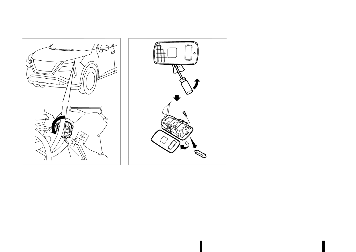
(450,1)
446 Maintenance and do-it-yourself
MWAI0381X
Front turn signal light (bulb type)
MWAI0202X
Cargo light
LEGAL REQUIREMENT TO ADJUST
HEADLIGHT BEAM
MEVT33A1-0314034C-446F-44EF-8587-0452C8EBB4A0
When the vehicle is driven in a country where the
driving lane is different to your home country, affix
an opaque sticker on the headlight.
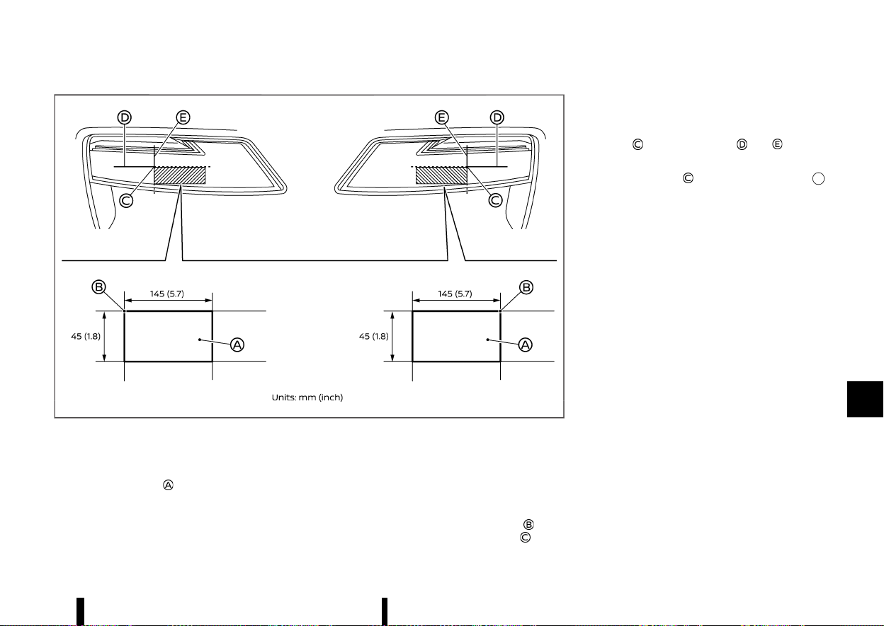
(451,1)
MWAI0345X
1. Place the ignition switch in the “OFF” position
and wait until the headlights cool down.
2. Prepare the stickers referring to the figure.
Make the stickers
that will be affixed to the
surface of the right side headlight and the left
side headlight.
NOTE:
.
Use an opaque material that prevents the
light from passing through it.
.
Note that other transparent materials do
not work effectively.
3. Affix the sticker by aligning the corner
of the
sticker with the position of the mark
that is
located on the surface of the headlight seen
from front.
Affix the sticker as illustrated by aligning the
mark
with dividing lines and .
NOTE:
Align the mark
with the centre mark
of the LED headlight.
Maintenance and do-it-yourself 447

(452,1)
448 Maintenance and do-it-yourself
MEVT33A1-F6BA5101-9D22-47BE-BE64-1C192428380D
If you have a flat tyre, see “Flat tyre” (P.405).
TYRE PRESSURE MONITORING SYSTEM
(TPMS)
MEVT33A1-D6EF18B1-2442-473D-A573-60D459B74FC7
The Tyre Pressure Monitoring System (TPMS)
monitors tyre pressure of all tyres. When the low
tyre pressure warning light is lit, one or more of
your tyres is significantly under-inflated.
The TPMS will activate only when the vehicle is
driven at speeds above 25 km/h (16 MPH). Also, this
system may not detect a sudden drop in tyre
pressure (for example a flat tyre while driving).
For more details, see “Low tyre pressure warning
light” (P.77), “Tyre Pressure Monitoring System
(TPMS)” (P.240) and “Tyre Pressure Monitoring
System (TPMS)” (P.405).
TYRE INFLATION PRESSURE
MEVT33A1-C57645B5-E413-4FCA-B110-F118428A3D6F
Periodically check the pressure of the tyres. An
incorrect tyre pressure may adversely affect tyre
life and vehicle handling. The tyre pressure should
be checked when tyres are COLD. Tyres are
considered COLD after the vehicle has been
parked for 3 or more hours, or driven less than
1.6 km (1 mile). COLD tyre pressures are shown on
the tyre placard.
Insufficient pressure can lead to an overheating of
the tyre and subsequent internal damage. At high
speeds, this could result in tread separation and
even bursting of the tyre.
TYPES OF TYRES
MEVT33A1-48074B24-5C3D-40BE-B898-94DBD0DB3114
CAUTION
When changing or replacing tyres, be sure all
four tyres are of the same type (that is,
summer, all season or snow) and construction.
A NISSAN dealer or qualified workshop may be
able to help you with information about tyre
type, size, speed rating and availability.
Replacement tyres may have a lower speed rating
than the factory equipped tyres, and they may not
match the potential maximum vehicle speed.
Never exceed the maximum speed rating of the
tyre.
All season tyres
MEVT33A1-C0D0571C-9967-4160-8D37-5FFAFDF5B227
NISSAN specifies all season tyres on some models
to provide good performance all year, including
snowy and icy road conditions. All season tyres are
identified by ALL SEASON and/or M&S on the tyre
sidewall. Snow tyres have better snow traction
than all season tyres and may be more appro-
priate in some areas.
Summer tyres
MEVT33A1-4E97CEC8-5073-48C3-B622-D6D0D72C8239
NISSAN specifies summer tyres on some models to
provide superior performance on dry roads. Sum-
mer tyre performance is substantially reduced in
snow and ice. Summer tyres do not have the tyre
traction rating M&S on the tyre sidewall.
If you plan to operate your vehicle in snowy or icy
conditions, NISSAN recommends the use of snow
or all season tyres on all four wheels.
Snow tyres
MEVT33A1-68F6B024-EDDD-469B-AD5B-EDF6F10A829E
If snow tyres are needed, it is necessary to select
tyres equivalent in size and load rating to the
original equipment tyres. If you do not, it can
adversely affect the safety and handling of your
vehicle.
Generally, snow tyres have lower speed ratings
than factory equipped tyres and may not match
the potential maximum vehicle speed. Never
exceed the maximum speed rating of the tyre. If
you install snow tyres, they must be the same size,
brand, construction and tread pattern on all four
wheels.
For additional traction on icy roads, studded tyres
may be used. However, some states and provinces
prohibit their use. Check local, state and provincial
laws before installing studded tyres. Skid and
traction capabilities of studded snow tyres on
wet or dry surfaces may be poorer than that of
non-studded snow tyres.
TYRE CHAINS
MEVT33A1-74141916-7668-4C78-8B9E-6B18B49D3DE7
CAUTION
* Tyre chains/cables should not be installed
on 255/45 R20 tyres. Doing so will cause
damage to the vehicle.
* If you plan to use tyre chains/cables, you
should install 235/60 R18 or 235/55 R19
tyres on your vehicle.
Use of tyre chains may be prohibited according to
location. Check the local laws before installing tyre
chains. When installing tyre chains, make sure they
TYRES AND WHEELS
TYRES AND WHEELS
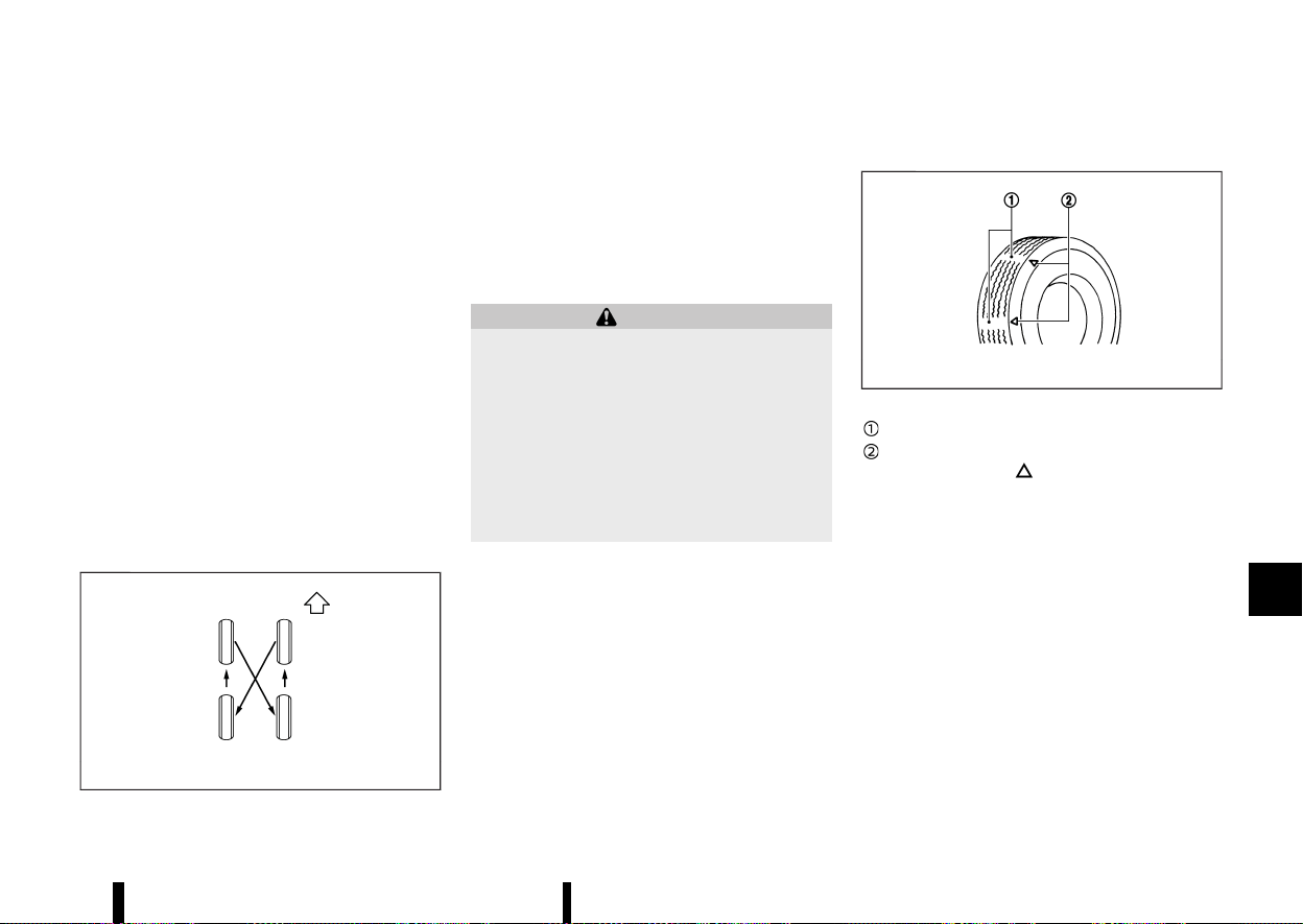
(453,1)
are the proper size for the tyres on your vehicle
and are installed according to the chain manufac-
turer’s suggestions. The minimum clearances are
determined using the factory equipped tyre size.
Other types may damage your vehicle. Use chain
tensioners when recommended by the tyre chain
manufacturer to ensure a tight fit. Loose end links
of the tyre chain must be secured or removed to
prevent the possibility of whipping action damage
to the fenders or underbody. If possible, avoid fully
loading your vehicle when using tyre chains. In
addition, drive at a reduced speed. Otherwise, your
vehicle may be damaged and/or vehicle handling
and performance may be adversely affected.
Tyre chains must be installed only on the front
wheels and not on the rear wheels.
Do not use tyre chains on dry roads. Driving with
tyre chains in such conditions can cause damage
to the various mechanisms of the vehicle due to
some overstress.
TYRE ROTATION
MEVT33A1-F5986E33-082B-45E2-BD27-0D11FB4C108F
MJVM0287X
NISSAN recommends that tyres be rotated every
10,000 km (6,000 miles). However, the timing for
tyre rotation may vary according to your driving
habits and the road surface conditions. (See
“Jacking up vehicle and replacing tyres” (P.450)
for the tyre replacement.)
As soon as possible, tighten the wheel nuts to
the specified torque with a torque wrench.
WARNING
* After rotating the tyres, adjust the tyre
pressure.
* Retighten the wheel nuts when the vehicle
has been driven for 1,000 km (600 miles)
(also in cases of a flat tyre, etc.).
* Incorrect tyre selection, fitting, care, or
maintenance can affect vehicle safety with
risk of accident and injury. If in doubt,
consult a NISSAN dealer or qualified work-
shop or the tyre manufacturer.
After the tyres are rotated, the TPMS must be reset.
(See “Tyre Pressure Monitoring System (TPMS)”
(P.240) for details about the resetting procedure.)
TYRE WEAR AND DAMAGE
MEVT33A1-31749D32-974E-4A82-89B7-A06D0BF3E07F
MSDI1663
Wear indicator
Wear indicator location marks. The locations
are shown by “
”, “TWI”, etc. depending on
tyre types.
Tyres should be periodically inspected for wear,
cracking, bulging or objects caught in the tread. If
excessive wear, cracks, bulging or deep cuts are
found, the tyre should be replaced immediately.
The original tyres have a built-in tread wear
indicator. When the wear indicator is visible, the
tyre should be replaced.
TYRE AGE
MEVT33A1-87474BCE-AB9F-411F-AB9B-F1AA39ED4BC0
Never use a tyre over six years old, regardless of
whether it has been used or not.
Tyres degrade with age as well as with the vehicle
usage. Have your tyres checked and balanced
often by a repair shop or, if you prefer, a NISSAN
dealer or qualified workshop.
Maintenance and do-it-yourself 449

(454,1)
450 Maintenance and do-it-yourself
CHANGING TYRES AND WHEELS
MEVT33A1-41BC763C-419B-45A4-AD0E-D41987D9B9CC
WARNING
Do not install a deformed wheel or tyre even if
it has been repaired. Such wheels or tyres
could have structural damage and could fail
without warning.
When replacing a tyre, use the same size, speed
rating and load carrying capacity as originally
equipped. (See “Tyres and Wheels” (P.448) for
recommended types and sizes of tyres and
wheels.) The use of tyres other than those
recommended or the mixed use of tyres of
different brands, construction (bias, bias-belted,
or radial), or tread patterns can adversely affect
the ride, braking, handling, ground clearance,
body-to-tyre clearance, snow chain clearance,
Tyre Pressure Monitoring System (TPMS), speed-
ometer calibration, headlight aim and bumper
height. Some of these effects may lead to acci-
dents and could result in serious personal injury.
If the wheels are changed for any reason, always
replace with wheels which have the same offset
dimension. Wheels of a different offset could cause
early tyre wear, possibly degraded vehicle handling
characteristics and/or interference with the brake
discs/drums. Such interference can lead to de-
creased braking efficiency and/or early brake pad/
shoe wear.
Confirm the following for the TPMS.
WARNING
* If your vehicle was originally equipped with
4 tyres that were the same size and you
are only replacing 2 of the 4 tyres, install
the new tyres on the rear axle. Placing new
tyres on the front axle may cause loss of
vehicle control in some driving conditions
and cause an accident and personal injury.
* After a tyre or a wheel is replaced, the
TPMS must be reset. (See “Tyre Pressure
Monitoring System (TPMS)” (P.240) for de-
tails about the resetting procedure.)
* Replacing tyres with those not originally
specified by NISSAN could affect the prop-
er operation of the TPMS.
* The TPMS sensor may be damaged if it is
not handled correctly. Be careful when
handling the TPMS sensor.
* When replacing the TPMS sensor, the ID
registration may be required. Contact a
NISSAN dealer or qualified workshop for ID
registration.
* Do not use a valve stem cap that is not
specified by NISSAN. The valve stem cap
may become stuck.
* Be sure that the valve stem caps are
correctly fitted. Otherwise the valve may
be clogged up with dirt and cause a
malfunction or loss of pressure.
* Do not install a damaged or deformed
wheel or tyre even if it has been repaired.
Such wheels or tyres could have structural
damage and could fail without warning.
* The use of retread tyre is not recom-
mended.
WHEEL BALANCE
MEVT33A1-89DC94BE-30B6-4D4F-83D4-7CDA2484D5D9
Unbalanced wheels may affect vehicle handling
and tyre life. Even with regular use, wheels can get
out of balance. Therefore, they should be balanced
as required.
JACKING UP VEHICLE AND REPLACING
TYRES
MEVT33A1-081295B6-3027-4861-9BF7-9260D4AC0D65
This section provides the information about the
vehicle jack-up procedures and the tyre replace-
ment.
You can temporarily fix a minor tyre puncture
using the emergency tyre puncture repair kit. (See
“Repairing flat tyre” (P.405).)
WARNING
* Be sure to apply the parking brake firmly.
* Be sure to press the park button to engage
the P (Park) position.
* Never change tyres when the vehicle is on
a slope, ice or slippery area. This is hazar-
dous.
* Never change tyres when the oncoming
traffic is close to your vehicle. Call for
professional road assistance.
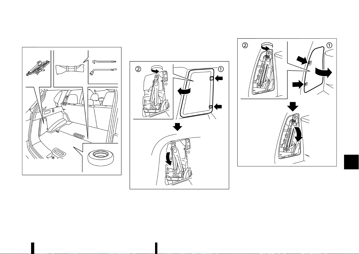
(455,1)
Preparing tools
MEVT33A1-12081696-3800-4A96-B921-65EAEC6B42F1
MWAI0347X
Model with adjustable luggage floor
Open the back door. Raise the luggage floor board.
Remove the jacking tools.
The jack, jack rod and wheel nut wrench are not
equipped as standard with this vehicle. Contact
a NISSAN dealer or qualified workshop about
acquiring the tools.
MWAG0064X
Two row model
MWAI0348X
Three row model
To remove the jack:
1. Remove the storage door by pressing the two
release tabs simultaneously.
2. Turn the jack lever in a counter-clockwise
direction, and then remove the jack slowly.
When storing the jack, set the jack slowly back,
then turn the jack lever in a clockwise direction
until the jack is fixed.
Maintenance and do-it-yourself 451
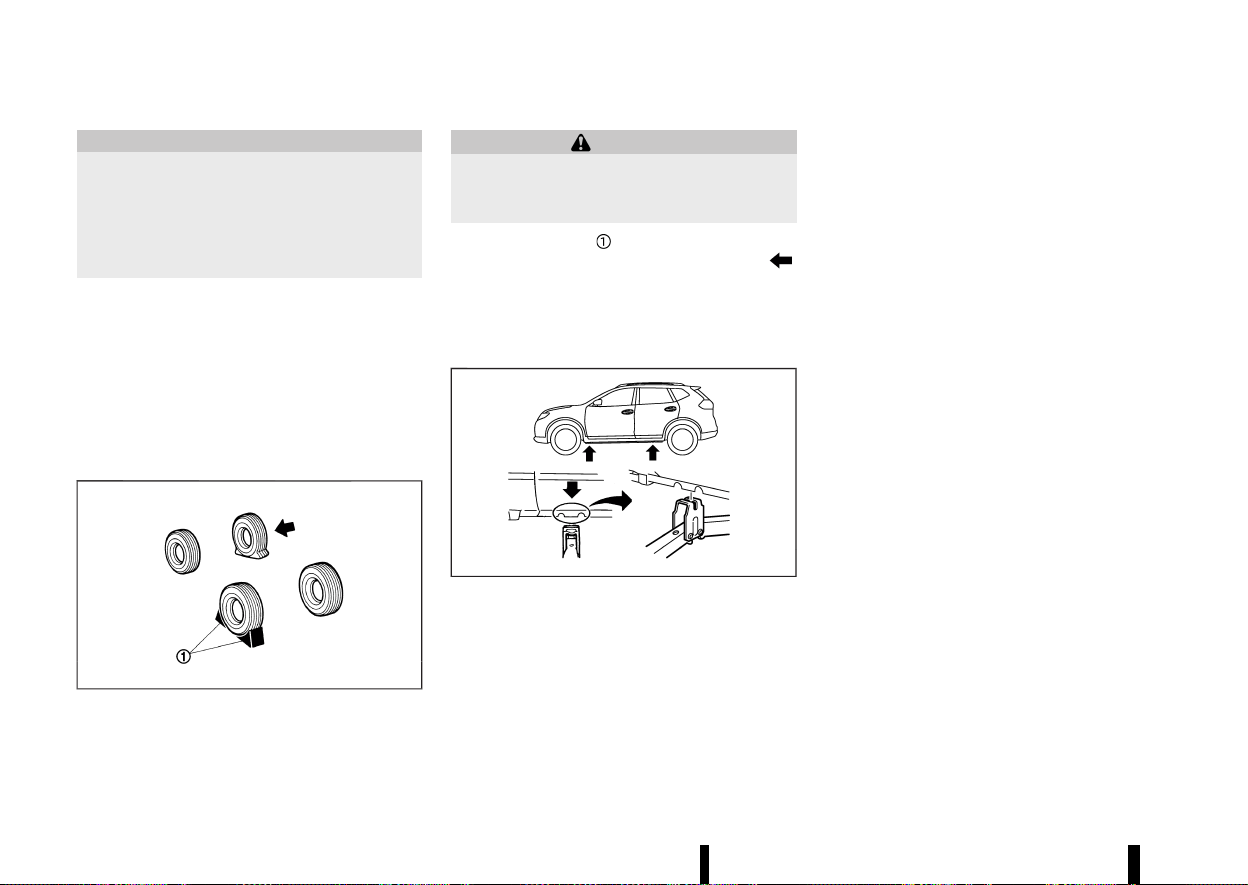
(456,1)
452 Maintenance and do-it-yourself
CAUTION
* Do not touch floor metal directly. Doing so
could result in any burns.
* When removing the jack, be careful that
your hands do not hit against the vehicle.
Otherwise, this could result in personal
injury.
NOTE:
* When storing the jack, do not overtighten
the jack lever using a screw driver. Doing so
could cause deformation of the installation
area for the jack.
* Do not allow the jack to contact the interior
parts. Doing so could cause damage to the
vehicle.
Blocking wheels
MEVT33A1-DD9C8115-ABFC-4D1E-83CA-B42FA1804F6F
MMCE0001A
WARNING
Be sure to block the appropriate wheel to
prevent the vehicle from moving, which may
cause personal injury.
Place suitable blocks
at both the front and back
of the wheel diagonally opposite the flat tyre
to prevent the vehicle from moving when it is
jacked up.
Removing tyre
MEVT33A1-802D21F0-175D-45CE-9BE1-17380BB6606C
Jacking up vehicle:
MJVE0165X
jack-up points
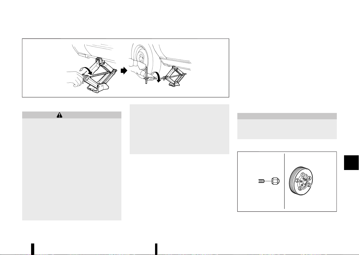
(457,1)
MSCE0504
WARNING
* Be sure to read and follow the instructions
in this section.
* DO NOT GET UNDER A VEHICLE THAT IS
SUPPORTED BY A JACK.
* Never use a jack which was not provided
with your vehicle.
* The jack, which is provided with your
vehicle, is designed only to lift your vehicle
during a tyre change. Do not use the jack
provided with your vehicle on other vehi-
cles.
* Never jack up the vehicle at a location
other than the jack-up point that is speci-
fied.
* Never lift the vehicle more than necessary.
* Never use blocks on or under the jack.
* Never start the vehicle while the vehicle is
on the jack. The vehicle may move sud-
denly, and this may cause an accident.
* Never allow passengers to remain in the
vehicle while the tyre is off the ground.
* Be sure to read the caution label attached
to the jack body before using.
* When jacking up the vehicle, be sure to
apply the parking brake.
1. Place the jack directly under the jack-up point
as illustrated so that the top of the jack
contacts the vehicle at the jack-up point.
The jack should be placed on firm level
ground.
2. Align the jack head between the two notches
located at the jack-up point of either the front
or the rear section.
3. Fit the groove of the jack head between the
notches as shown.
4. Loosen each wheel nut, anticlockwise, one or
two turns with the wheel nut wrench.
Do not remove the wheel nuts until the tyre
is off the ground.
5. Carefully raise the vehicle until the clearance
between the tyre and ground is achieved.
6. To lift the vehicle, securely hold the jack lever
and rod with both hands and turn the jack
lever.
Removing tyre:
1. Remove the wheel nuts.
2. Remove the damaged tyre.
CAUTION
The tyre is heavy. Be sure that your feet are
clear from the tyre and use gloves as neces-
sary to avoid injury.
Installing tyre
MEVT33A1-42955B61-7830-4F30-BFFB-499EBF253CFB
MSCE0933
Maintenance and do-it-yourself 453

(458,1)
454 Maintenance and do-it-yourself
WARNING
* Never use wheel nuts which are not pro-
vided with your vehicle. Incorrect wheel
nuts or improperly tightened wheel nuts
may cause the wheel to become loose or
come off. This could cause an accident.
* Never use oil or grease on the wheel studs
or nuts. This may cause the wheel nuts to
become loose.
1. Clean any mud or dirt from the surface
between the wheel and hub.
2. Carefully put the tyre on and tighten the wheel
nuts with your fingers. Check that all the wheel
nuts contact the wheel surface horizontally.
3. Tighten the wheel nuts alternately and evenly,
more than 2 times in the sequence illustrated
(
- ), with the wheel nut wrench, until they
are tight.
4. Lower the vehicle slowly until the tyre touches
the ground.
5. Tighten the wheel nuts securely, with the
wheel nut wrench, in the sequence illustrated.
6. Lower the vehicle completely.
Tighten the wheel nuts to the specified torque
with a torque wrench as soon as possible.
Wheel nut tightening torque:
108 Nm (11 kg-m, 80 ft-lb)
The wheel nuts must be kept tightened to
specification at all times. It is recommended
that the wheel nuts be tightened to specification
at each lubrication interval.
* After adjusting the tyre pressure, the TPMS
must be reset. (See “Tyre Pressure Monitoring
System (TPMS)” (P.240) for details about the
resetting procedure.)
* After adjusting tyre pressure to the COLD tyre
pressure, the display of the tyre pressures may
show higher pressure than the COLD tyre
pressure after the vehicle has been driven
more than 1.6 km (1 mile). This is because the
tyre pressurises as tyre temperature rises. This
does not indicate a system malfunction.
Stowing damaged tyre and tools
MEVT33A1-AFB1BD8D-1F70-4624-8F89-C7C114341985
WARNING
Be sure that the tyre, jack and tools used are
properly stored after use. Such items can
become dangerous projectiles in an accident
or sudden stop.
1. Securely store the damaged tyre, jack and
tools used in the storage area.
2. Replace the luggage floor board.
3. Close the back door.
EMERGENCY TYRE PUNCTURE REPAIR
KIT
MEVT33A1-B0897C4F-E50A-461B-B6FE-491E323B2C92
The emergency tyre puncture repair kit is supplied
to the vehicle instead of a spare tyre. The kit must
be used for temporarily fixing a minor tyre
puncture. After using the repair kit, see a NISSAN
dealer or qualified workshop as soon as possible
for tyre inspection and repair/replacement.
See “Flat tyre” (P.405) for more details.

(459,1)
9 Technical information
Recommended fluids/lubricants and capacities ............... 456
Fuel information ................................................................................. 458
Recommended SAE viscosity number ............................. 458
Air conditioner system refrigerant
and lubricant ........................................................................................ 458
Engine ................................................................................................................... 460
Tyres and wheels ........................................................................................ 461
Dimensions ....................................................................................................... 461
When travelling or registering in another country .......... 462
Vehicle identification ................................................................................ 462
Vehicle identification label ......................................................... 462
Vehicle Identification Number (VIN) .................................... 462
Engine serial number
....
................................................................. 462
Tyre placard
....
....................................................................................... 462
Air conditioner specification label
....
................................... 463
Installation of an RF-transmitter
....
................................................ 463
Additional data recording (on vehicles equipped with
optional ProPILOT Assist)
....
.................................................................. 463
Radio approval number and information
....
............................ 465
For Europe
....
.......................................................................................... 465
For Morocco
....
...................................................................................... 468
For Ukraine
....
......................................................................................... 469
For the United Kingdom
....
.......................................................... 470
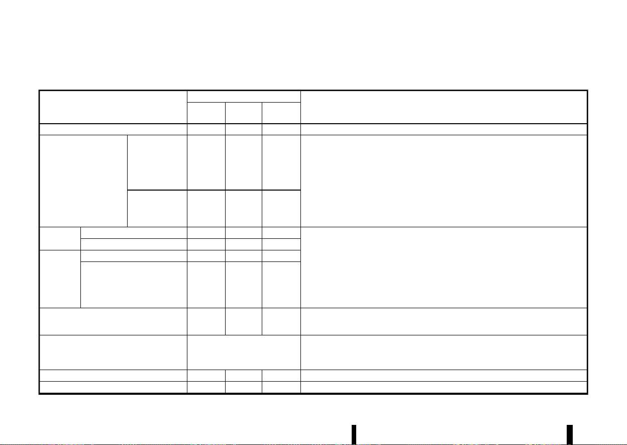
(460,1)
456 Technical information
MEVT33A1-D9645BC2-ADAD-47D0-AF0B-FB1E7AD887A1
The following are approximate capacities. The actual refill quantities may be slightly different. When refilling, follow the procedures instructed in the “8.
Maintenance and do-it-yourself” section to determine the proper refill capacity.
Fluid type
Capacity (approximate)
Recommended Fluids/Lubricants
Metric
Measure
US
Measure
Imperial
Measure
Fuel
55 L 14–1/2 gal 12–1/8 gal
· See “Fuel information” (P.458).
Engine oil
*1
With oil filter
4.7 L 5 qt 4-1/8 qt
· Genuine “NISSAN Motor Oil 0W-20 SP” is recommended.
· If "Nissan Motor Oil 0W-20 SP" is not available, "Nissan Motor Oil 0W-20 SN" is also
recommended.
· If the above motor oil is not available, use "NISSAN Motor Oil" or equivalent that matches the
following grade and viscosity.
· Oil grade:
– API: SN or SP, ILSAC GF-5 or GF-6
· SAE Viscosity: See “Recommended SAE viscosity number” (P.458).
Drain and refill
*1
: For additional informa-
tion, see “Changing engine
oil and filter” (P.430).
Without oil filter
4.6 L 4-7/8 qt 4 qt
Engine cool-
ant
With reservoir
8.5 L 9 qt 7–1/2 qt
For Europe
· Genuine NISSAN Engine Coolant or equivalent in its quality
*2
Except for Europe
· Genuine NISSAN Engine Coolant (blue) or equivalent
*2
*2
: Use Genuine NISSAN Engine Coolant or equivalent in its quality, in order to avoid possible
aluminium corrosion within the engine cooling system caused by the use of non-genuine
engine coolant.
Note that any repairs for the incidents within the engine cooling system while using non-
genuine engine coolant may not be covered by the warranty even if such incidents occurred
during the warranty period.
Reservoir
0.8 L 7/8 qt
3/4 qt
Intercooler
coolant
With reservoir
3.0 L 3–1/8 qt
2–5/8 qt
Reservoir
0.5 L 1/2 qt
1/2 qt
Continuously Variable Transmission (CVT) fluid
— — —
· Genuine NISSAN CVT Fluid NS-3
· Use only Genuine NISSAN CVT Fluid NS-3. Using transmission fluid other than Genuine NISSAN
CVT Fluid NS-3 may damage the CVT, which is not covered by the warranty.
Brake fluid
Refill to the proper fluid level accord-
ing to the instructions in the “8.
Maintenance and do-it-yourself” sec-
tion.
· Genuine NISSAN Brake Fluid or equivalent DOT3 or DOT4
· Never mix different types of fluids (DOT3 and DOT4).
Multi-purpose grease
— — —
· NLGI No. 2 (Lithium soap base)
Air conditioner system refrigerant
— — —
· HFO-1234yf (R-1234yf)
RECOMMENDED FLUIDS/LUBRI-
CANTS AND CAPACITIES
RECOMMENDED FLUIDS/LUBRICANTS AND CAPACITIES
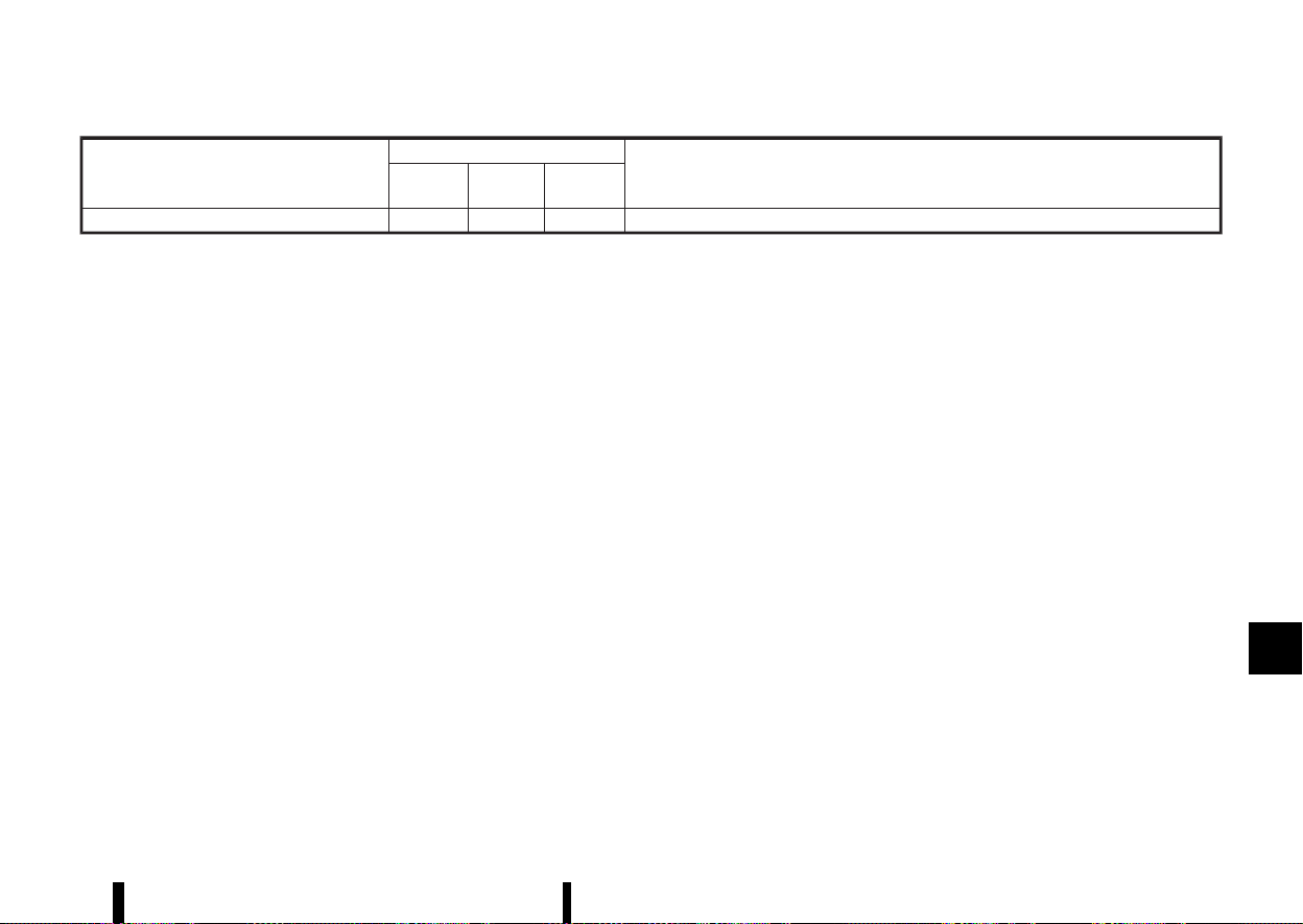
(461,1)
Fluid type
Capacity (approximate)
Recommended Fluids/Lubricants
Metric
Measure
US
Measure
Imperial
Measure
Air conditioner system lubricants
— — —
· AC system oil VC100yf or equivalent
Technical information 457
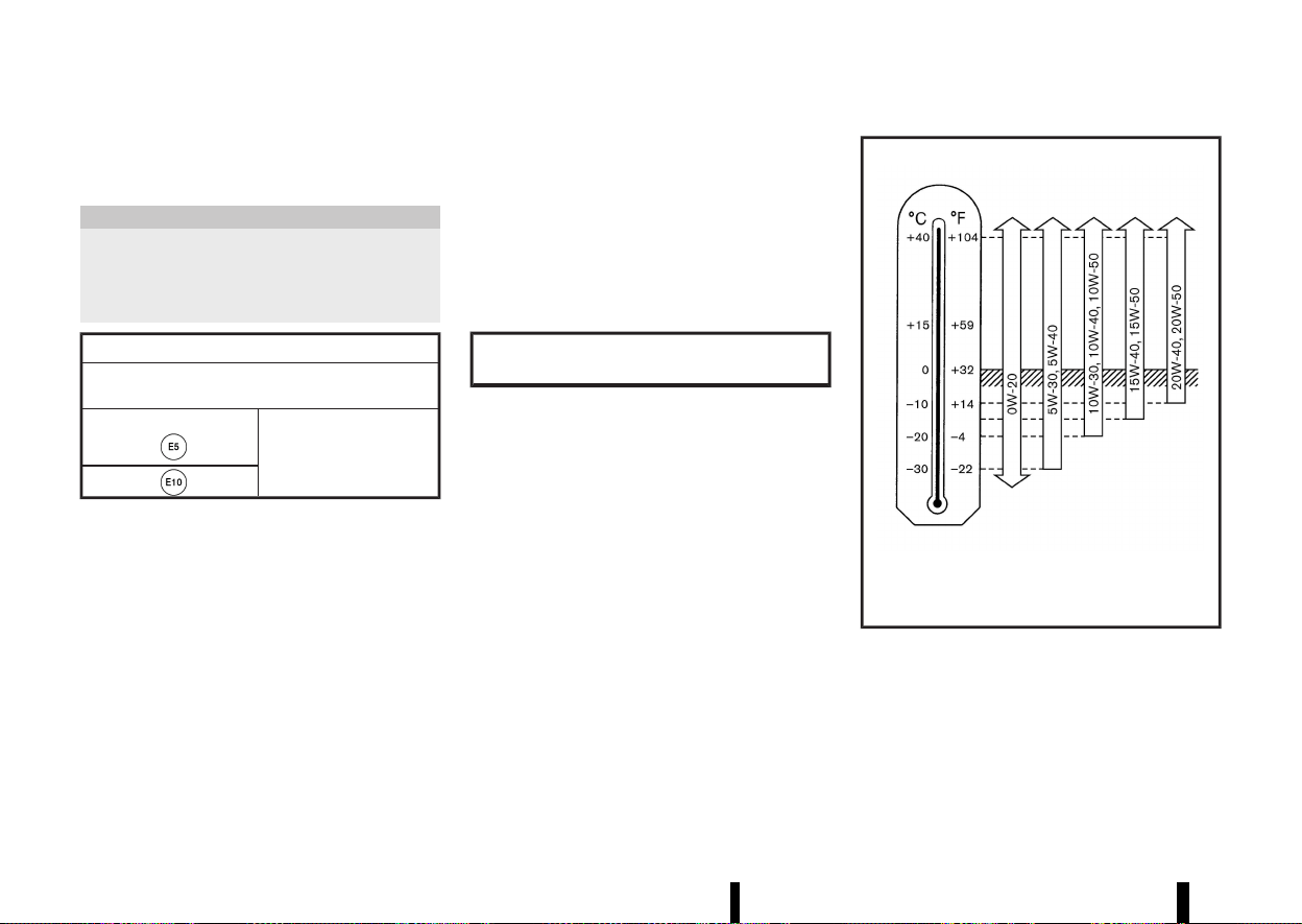
(462,1)
458 Technical information
FUEL INFORMATION
MEVT33A1-2E3748A0-F569-443A-AE2B-2AE00543793D
Petrol engine
MEVT33A1-9B5A83E0-BBB3-461C-A0A5-7F959D57907F
CAUTION
* Do not use leaded petrol. Using leaded
petrol will damage the three-way catalyst.
* Never use fuel additives. Additives may
cause damage to the engine.
Compatible fuels for petrol engines (for Europe)
The petrol engines are compatible with current and
future European standards for bio-fuel.
Petrol conforming to
EN228 and mixed with a
bio-fuel conforming to
EN15376.
Use UNLEADED PREMIUM petrol with an octane
rating of at least 95 (RON).
If unleaded premium petrol is not used, UNLEADED
REGULAR petrol with an octane rating of at least 91
(RON) may be used at slightly reduced perfor-
mance. However, for maximum vehicle perfor-
mance and the best driveability, the use of
unleaded premium petrol is recommended.
RECOMMENDED SAE VISCOSITY NUM-
BER
MEVT33A1-B568291B-A6B6-4A88-A2FD-1DD8110EC5AD
Petrol engine oil
MEVT33A1-01BB96E1-AB70-4BD8-B49C-D9123355C3B1
0W-20 is preferable.
If 0W-20 is not available, select the viscosity, from
the chart below, that is suitable for the outside
temperature range.
Outside Temperature Range
Anticipated Before Next Oil Change
PETROL ENGINE OIL
MNTI311
AIR CONDITIONER SYSTEM REFRIGER-
ANT AND LUBRICANT
MEVT33A1-B34FA0EF-3042-4280-ADDF-5F05487BB3B9
The air conditioner system of your vehicle must be
charged with the refrigerant HFO-1234yf (R-1234yf)
and the lubricant AC system oil VC100yf or
equivalent. Use of any other refrigerants or lubri-
cants will cause severe damage, and you may need

(463,1)
to replace your vehicle’s entire air conditioner
system.
The release of refrigerants into the atmosphere is
prohibited in many countries and regions. The
refrigerant in your vehicle will not harm the Earth’s
ozone layer. However, it may contribute in a small
part to the global warming effect. NISSAN recom-
mends that the refrigerant be appropriately re-
covered and recycled. Contact a NISSAN dealer or
qualified workshop when servicing the air condi-
tioner system.
Technical information 459

(464,1)
460 Technical information
MEVT33A1-F2408CB9-71B9-4DD3-B815-969B445213AD
Engine model
KR15DDT
Type
Petrol, 4-cycle, DOHC
Cylinder arrangement
3-cylinder, in-line
Bore × Stroke
when compression ratio = 8 mm (in)
84.0 × 90.1 (3.307 × 3.547)
when compression ratio = 14 mm (in)
84.0 × 88.9 (3.307 × 3.500)
Displacement
when compression ratio = 8 cm
3
(cu in)
1,497 (91.4)
when compression ratio = 14 cm
3
(cu in)
1,477 (90.1)
Idle speed rpm
800±50
Ignition timing (B.T.D.C.) degree at idle
- 6° to 9°
Spark plugs
Type Standard
ILMAR8G8GS
Gap mm (in)
0.8 (0.031)
Camshaft operation
Timing chain
ENGINE
ENGINE

(465,1)
MEVT33A1-78C4B2D5-FD92-48BA-A160-7F4269BEFC7B
Standard
Spare
Tyre size
235/60 R18
- (*)235/55 R19
255/45 R20
Size
Offset mm (in)
Road wheel Aluminium
18 × 7.5J
40 (1.57)
19 × 7.5J
40 (1.57)
20 × 8J
45 (1.77)
Spare - (*) - (*)
- (*)
*: The emergency tyre puncture repair kit is
supplied.
MEVT33A1-AD9E6292-C28E-4F5A-ADB0-5FD3EBDA5728
Unit: mm (in)
Overall length 4,680 (184.3)
Overall width 1,840 (72.4)
Overall height 1,725 (67.9)
Front tread 1,585 (62.4)*1
1,575 (62.0)*2
Rear tread 1,590 (62.6)*1
1,580 (62.2)*2
Wheelbase 2,705 (106.5)
*1: Except for 20-inch wheel model
*2: For 20-inch wheel model
Technical information 461
TYRES AND WHEELS
TYRES AND WHEELS
DIMENSIONS
DIMENSIONS
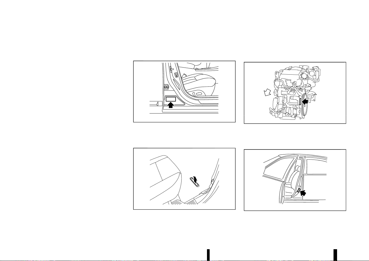
(466,1)
462 Technical information
MEVT33A1-E2898BB8-45F8-4579-80B8-57AD4758A332
When planning to travel in another country or
region, find out whether the fuel required for your
vehicle is available in that country or region. Using
a low octane rated fuel may cause engine damage.
Therefore, be sure that the required fuel is avail-
able wherever you go. For additional information
regarding recommended fuel, see earlier in this
section.
When transferring the registration of your vehi-
cle to another country, state, province or district,
contact the appropriate authorities to find out that
the vehicle complies with the local legal require-
ments. In some cases, a vehicle cannot meet the
legal requirements, and it may be necessary to
modify the vehicle to meet local laws and regula-
tions. In addition, there may be possibilities that a
vehicle cannot be adapted in certain areas.
The laws and regulations for motor vehicle emis-
sion control and safety standards vary according
to the country, state, province or district; therefore,
the vehicle specification may differ.
When any vehicles are to be taken into another
country, state, province or district, its modifica-
tion, transportation, registration, and any other
expenses which may result, are the responsi-
bility of the user. NISSAN is not responsible for
any inconveniences that may result.
MEVT33A1-388A0CF7-B0D9-4D6A-9F3A-183A6D5F9FB8
It is prohibited to cover, paint, weld, cut, drill, alter
or remove Vehicle Identification Number (VIN).
VEHICLE IDENTIFICATION LABEL
MEVT33A1-EFD45008-3882-4907-8050-F13128806C6A
MJVT0186X
The vehicle identification plate is affixed as shown.
VEHICLE IDENTIFICATION NUMBER (VIN)
MEVT33A1-9A22E6CA-C8D1-44C0-B821-A0AFEFF95529
MWAJ0405X
The vehicle identification number is located as
shown.
The surface is painted after stamping for rust
prevention.
ENGINE SERIAL NUMBER
MEVT33A1-751ACEEC-F138-40DF-8410-28E34BAFEFF3
MWAJ0221X
The engine serial numbers are located as shown.
TYRE PLACARD
MEVT33A1-8D4492E2-6D53-44C9-B315-EEA58BB066D8
MSTI0494
The cold tyre pressures are shown on the tyre
placard affixed to the driver’s side centre pillar.
WHEN TRAVELLING OR REGIS-
TERING IN ANOTHER COUNTRY
WHEN TRAVELLING OR REGIS-
TERING IN ANOTHER COUNTRY
VEHICLE IDENTIFICATION
VEHICLE IDENTIFICATION
(467,1)
AIR CONDITIONER SPECIFICATION LA-
BEL
MEVT33A1-2C4F9D07-6274-4D82-AD0C-E4E9C9FDBA6E
MWAJ0153X
The air conditioner specification label is attached
to the underside of the bonnet as shown.
MEVT33A1-81D0E033-48B7-4315-BFFE-D7085F76E610
For countries conforming to UN regulation No.10
or equivalent:
The installation of an RF transmitter in your vehicle
could affect electric equipment systems. Be sure to
check with your NISSAN dealer or qualified work-
shop for precautionary measures or special in-
structions regarding installation. Upon request,
your NISSAN dealer or qualified workshop will
provide the detailed information (frequency band,
power, antenna position, installation guide, etc.)
regarding installation.
MEVT33A1-1932AB47-6C81-4494-92AB-4E83633AC85E
If your vehicle is equipped with the optional
ProPILOT Assist, it will also be equipped with
supplemental data recording function intended
to assist in understanding how ProPILOT Assist
performs in certain non-trivial crash or near-crash
scenarios. Specifically, supplemental recording is
designed to capture the following:
* Driver operational status of the accelerator,
brakes, steering, etc.
* Detection status of a vehicle ahead and lane
markers
* Vehicle information including distance to ve-
hicle ahead and lateral position
* Information on the operation of the ProPILOT
Assist and other crash avoidance features
* ProPILOT Assist malfunction diagnosis infor-
mation
* External images from the multi-sensing front
camera (Available only when the SRS air bag or
Intelligent Emergency Braking system is acti-
vated)
The ProPILOT Assist does not record conversa-
tions, sounds or images of the inside of the vehicle.
To read this supplemental data, special equipment
is required and access to the vehicle or the
recording unit is needed. This supplemental data
will only be accessed with the consent of the
vehicle owner or lessee or as otherwise required or
permitted by law. If downloaded, NISSAN and third
parties entrusted by NISSAN may use the data
recorded for the purpose of improving NISSAN’s
vehicle safety performance.
NISSAN and third parties entrusted by NISSAN will
Technical information 463
INSTALLATION OF AN RF-TRANSMITTER
INSTALLATION OF AN RF-TRANSMITTER
ADDITIONAL DATA RECORDING (on vehicles
equipped with optional ProPILOT Assist)
ADDITIONAL DATA RECORDING (on vehicles
equipped with optional ProPILOT Assist)

(468,1)
464 Technical information
not disclose/provide the recorded data to a third
party except:
* With the consent of the vehicle owner or with
the consent of the lessee
* In response to an official request from law
enforcement, court order, governmental
agency, or other legally enforceable request
* For research purposes after the data is
modified such that it is no longer tied to a
specific vehicle or vehicle owner (anonymized)

(469,1)
MEVT33A1-AFCFF5C2-90DD-463B-8A68-E8ADAE3128BD
FOR EUROPE
MEVT33A1-4F2F5F2E-C304-483E-9DFD-AABFB43CD2CD
Radio frequency approval
GUID-51F2E66C-687D-41B1-9F2C-1B2FEF4430BD
All radio frequency products fitted to the vehicle range during production conform to the requirements of the Radio Equipment Directive (RED) 2014/53/EU.
The countries covered by this directive, or those which accept it, are: Albania, Austria, Belgium, Bosnia & Herzegovina, Bulgaria, Croatia, Cyprus, Czech Republic,
Denmark, Estonia, Finland, France, French Guiana, Georgia, Germany, Greece, Guadeloupe, Hungary, Iceland, Ireland, Italy, Kosovo, Latvia, Liechtenstein, Lithuania,
Luxembourg, Macedonia, Malta, Martinique, Mayotte, Monaco, Montenegro, Netherlands, Norway, Poland, Portugal, Reunion, Romania, Saint Pierre & Miquelon, San
Marino, Slovakia, Slovenia, Spain, Sweden, Switzerland, Turkey, Tuvalu, United Kingdom.
VEHICLE RADIO FUNCTIONS
Frequency Range Technology
Power/Magnetic Field
125 kHz (119 – 135 kHz) Remote Keyless Entry Transponder Ring
≤ 42 dBμA/m at 10m
433 MHz (433.05 – 434.79 MHz) Tyre Pressure Monitoring
≤ 10 mW e.r.p.
433.92 MHz (433.05 – 434.79 MHz) Remote Keyless Entry
≤ 10 mW e.r.p.
20 kHz (9 – 90 kHz) Keyless Go system
≤ 72 dBμA/m at 10m
2.4 GHz (2400 – 2483.5 MHz) Bluetooth
®
, Wi-Fi
≤ 100 mW e.i.r.p.
824 – 894 MHz GSM 850 (2G)
≤ 39 dBm e.i.r.p.
880 – 960 MHz GSM 900 (2G)
≤ 39 dBm e.i.r.p.
1710 – 1880 MHz GSM 1800 (2G)
≤ 36 dBm e.i.r.p.
1850 – 1890 MHz GSM 1900 (2G)
≤ 33 dBm e.i.r.p.
1922 – 2168 MHz W-CDMA Band I (3G)
≤ 24 dBm e.i.r.p.
24.05 – 24.25 GHz 24 GHz ISM Radar
≤ 100 mW e.i.r.p.
24.25 – 26.65 GHz 24 GHz UWB Radar
≤ -41,3 dBm/MHz e.i.r.p. mean
≤ 0 dBm/50 MHz e.i.r.p. peak
76 – 77 GHz 77 GHz Radar
≤ 55 dBm e.i.r.p.
Technical information 465
RADIO APPROVAL NUMBER
AND INFORMATION
RADIO APPROVAL NUMBER AND INFORMATION

(470,1)
466 Technical information
Tyre Pressure Monitoring System (TPMS) TRANSMITTER
MEVT33A1-939F60BA-5423-41DA-A9BB-A1BBFF000B5B
Hereby, Continental declares that the radio equip-
ment type TIS-09DL is in compliance with Directive
2014/53/EU.
The full text of the EU declaration of conformity is
available at the following internet address:
https://continental-homologation.com/en-gl/
Nissan
* Manufacturer name, Address
Continental Automotive GmbH
Siemensstrasse 12, D-93055 Regensburg, Ger-
many
* Importer name, Address
NISSAN AUTOMOTIVE EUROPE S.A.S.
8 Rue Jean Pierre Timbaud, 78180 Montigny-le-
Bretonneux FRANCE
* Frequency band: 433.92 MHz
* Maximum transmitter power: -17 dBm
Front radar sensor (where fitted)
MEVT33A1-CCA848C0-50B2-4B7A-9BDD-D9B73E548158
Simplified EU declaration of conformity Hereby, Robert Bosch GmbH declares that the radio
equipment type FR5CPEC is in compliance with
Directive 2014/53/EU. The full text of the EU
declaration of conformity is available at the follow-
ing internet address:
http://eu-doc.bosch.com
MNSY0105
(471,1)
Side radar sensor (where fitted)
MEVT33A1-56522929-CB8C-4C97-82FA-071CC688C583
Simplified EU declaration
of conformity
Hereby, APTIV, 42367
Wuppertal declares
that the radio equip-
ment type RN5TR is in
compliance with the
essential requirements
and other relevant pro-
visions of Directive
2014/53/EU (RED).
The original declaration
of conformity can be
accessed at the follow-
ing internet address:
www.aptiv.com/auto-
motive-homologation
Frequency band(s) in
which the radio equip-
ment operates:
76-77 GHz
Maximum radio-fre-
quency power trans-
mitted in the frequency
band(s) in which the
radio equipment oper-
ates:
30 dBm (1 W)
MNSY0105
Intelligent Key
MEVT33A1-25272E47-ACDE-4A06-A66E-61944162C5E3
Hereby, Continental declares that the radio equip-
ment type TXPZ1 is in compliance with Directive
2014/53/EU & UKCA requirement. The full text of
the EU & UKCA declaration of conformity is
available at the following internet address:
https://continental-homologation.com/en-gl/
Nissan
Intended use: Remote key fob
Manufacturer:
Continental Automotive GmbH
Siemensstrasse 12
93055 Regensburg
Germany
Frequency band: 433.92 MHz
Maximum transmitter power: -12 dBm
MWAJ0410X
Hands-Free Module (where fitted)
MEVT33A1-25C7EDD4-EF5A-4708-981A-4CBA302411DF
Hereby, Continental declares that the radio equip-
ment type HFM401 is in compliance with Directive
2014/53/EU & UKCA requirement. The full text of
the EU & UKCA declaration of conformity is
available at the following internet address:
https://continental-homologation.com/en-gl/
Nissan
Manufacturer:
Continental Automotive GmbH
Siemensstrasse 12
93055 Regensburg
Germany
* Operating frequency band: 433.92 MHz.
BCM (Body Control Module)
MEVT33A1-F87303C3-3B99-4C36-91C5-2D9D2EF8BAF5
Hereby, Continental declares that the radio equip-
ment type 40406557 is in compliance with Direc-
tive 2014/53/EU & UKCA requirement. The full text
of the EU & UKCA declaration of conformity is
available at the following internet address:
https://continental-homologation.com/en-gl/
Nissan
Manufacturer:
Continental Automotive GmbH
Siemensstrasse 12
93055 Regensburg
Germany
Technical information 467
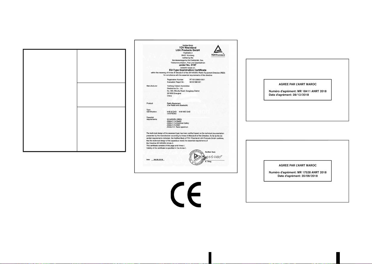
(472,1)
468 Technical information
Audio system (where fitted)
MEVT33A1-4457B5EA-5A08-4C60-B1D2-E98C30E9CC50
Simplified EU declaration
of conformity
Hereby Visteon Auto-
motive Electronics Co.,
Ltd. declares that this
system is in compliance
with Directive 2014/53/
EU.
Frequency band(s) in
which the radio equip-
ment operates:
2400–2483.5 MHz
Maximum radio-fre-
quency power trans-
mitted in the frequency
band(s) in which the
radio equipment oper-
ates:
Bluetooth <10 mW
(EIRP)
Hereby Visteon Automotive Electronics Co., Ltd.
declares that this system is in compliance with
Directive 2014/53/EU.
* Importer name, address:
NISSAN AUTOMOTIVE EUROPE S.A.S.
8 Rue Jean Pierre Timbaud, 78180 Montigny-le-
Bretonneux FRANCE
* Operating frequency range:
2400–2483.5 MHz
* Maximum power: <10 mW e.i.r.p.
MWAJ0411X
MNSY0105
FOR MOROCCO
MEVT33A1-E57E6760-5995-41C4-B861-C63622B6DF8D
Tyre Pressure Monitoring System (TPMS) TRANSMITTER
MEVT33A1-ED687EAC-9B98-4C6E-B70A-2228B2F51513
MWAJ0402X
Front radar sensor (where fitted)
MEVT33A1-9FB3042E-8E07-49E4-9ACB-10C11B87BE72
MWAJ0412X
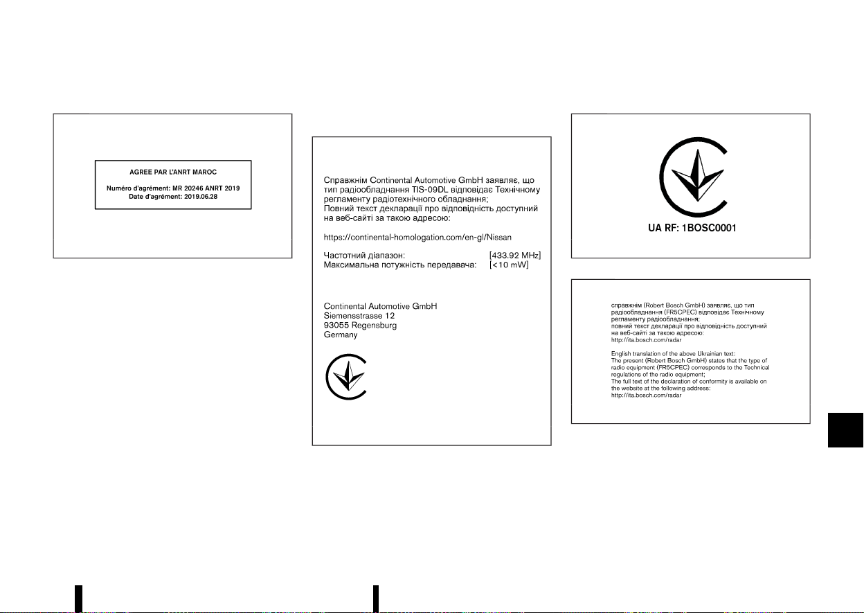
(473,1)
Side radar sensor (where fitted)
MEVT33A1-0AA0BE0B-ED59-485C-A5CB-781F6EB6671A
MWAJ0413X
FOR UKRAINE
MEVT33A1-C8437E64-1368-455B-921F-AE956D9415FC
Tyre Pressure Monitoring System (TPMS) TRANSMITTER
MEVT33A1-B6875E7D-B919-464B-86A5-6188AA00DB47
MWAJ0445X
Front radar sensor (where fitted)
MEVT33A1-EC7C933F-2AA2-4250-BA88-926CE73D71D1
MWAJ0414X
MWAJ0415X
Technical information 469
(474,1)
470 Technical information
Side radar sensor (where fitted)
MEVT33A1-5CC4D7B1-071F-4FCF-97B3-468AF5F6C4BC
MWAJ0416X
MWAJ0417X
Audio system (where fitted)
MEVT33A1-CCA8AD34-D9D0-48C2-8F7E-4F28265456E2
MJVT0276X
FOR THE UNITED KINGDOM
MEVT33A1-344DA077-64B9-46E0-9533-2B71EF7D3191
MWAJ0410X

(475,1)
Description Supplier Supplier Address
UKCA
Certificate #
Link to Certificate Importer
Importer Ad-
dress
Intelligent Key
Model TXPZ1
Continental Auto-
motive GmbH
Siemensstrasse 12, D-93055
Regensburg, Germany
Refer to Link
https://continental-homologation.
com/en-gl/Nissan
Nissan Mo-
tors Great
Britain
(NMGB)
Rivers Office
Park Denham
Way Rickmans-
worth WD3 9YS
Hand Free Module
Model HFM401
Continental Auto-
motive GmbH
Siemensstrasse 12, D-93055
Regensburg, Germany
Refer to Link
https://continental-homologation.
com/en-gl/Nissan
Telematics Control
Unit (TCU) Model A-
IVCEU- 01
VALEO Telematik
und Akustik GmbH
Max-Planck-Strasse 28-32,
61381 Friedrichsdorf/Ts
Germany
Refer to Link
https://www.valeo.com/declaration-
of-conformity
Body Control Mod-
ule (BCM) Model
40406557
Continental Auto-
motive GmbH
Siemensstrasse 12, D-93055
Regensburg, Germany
Refer to Link
https://continental-homologation.
com/en-gl/Nissan
Tire Pressure Mon-
itoring System
(TPMS) sensor Mod-
el TIS- 09DL
Continental Auto-
motive GmbH
Siemensstrasse 12, D-93055
Regensburg, Germany
Refer to Link
https://continental-homologation.
com/en-gl/Nissan
Front radar sensor
Model FR5CPEC
Robert Bosch
GmbH
P0 Box 1661
71226, Leonberg
Refer to Link
https://ita.bosch.com
Side radar sensor
Model RN5TR
Aptiv Services
Deutschland
GmbH
Am Technologiepark 1
D–42119 Wuppertal
Germany
Refer to Link
https://www.aptiv.com/en/automo-
tive- homologation
AIVI Model AIVI-
P33A0
Robert Bosch
GmbH
Postfach 31132
Hildesheim
Germany
Refer to Link
https://doc-ita.bosch.com/search.
html?r=GB&p=0&q=AIVIP33A0
AIVI Model AI-
VI2SBXM
Robert Bosch
GmbH
Postfach 31132
Hildesheim
Germany
Refer to Link
https://gb-doc.bosch.com
Technical information 471
(476,1)
472 Technical information
Description Supplier Supplier Address
UKCA
Certificate #
DECLARATION OF CONFORMITY Importer
Importer Ad-
dress
Audio system
Yanfeng Visteon
Automotive Elec-
tronics Co., Ltd.
No.300,Minolta Road, Songjiang
District, shanghai 201600, P.R.
China.
TUVS19- UK/17
SEP 2021/Rev A
Certification ID:TUVS19-UK/17 SEP
2021/Rev A
Nissan Motors
Great Britain
(NMGB)
Rivers Office
Park Denham
Way Rick-
mansworth
WD3 9YS
Satisfies all the technical regulations
applicable to the product within the
scope of UK Radio Equipment Regula-
tions (SI 2017/1206); UK Electrical
Equipment (Safety) Regulations (SI
2016/1101); and UK Electromagnetic
Compatibility Regulations (SI
2016/1091) and declare that the same
application has not been lodged with
any other UK Approved Body.
Bluetooth frequency band(s) in which
the radio equipment operates: 2402-
2480 MHz
Maximum radio-frequency power
transmitted in the frequency band(s) in
which the radio equipment operates:
Bluetooth < 5.86 dBm(EIRP)

(477,1)
10 Index
A
ABS (Anti-lock Braking System) .................................... 390
Active noise cancellation ................................................... 402
Active sound enhancement ............................................ 402
Adaptive LED headlight ....................................................... 110
Adjustable luggage floor .................................................... 130
Air bag system
- Air bag warning labels .................................................... 50
- Air bag warning light ....................................................... 51
- Supplemental curtain side-impact air
bag system ...................................................................... 47, 58
- Supplemental front central side-impact air
bag system ...................................................................... 47, 57
- Supplemental front-impact air
bag system ...................................................................... 47, 53
- Supplemental side-impact air
bag system ...................................................................... 47, 57
Air bag warning light ............................................................... 78
Air cleaner housing filter .................................................... 435
Air conditioner
- Air conditioner operation .......................................... 204
- Air conditioner service ................................................. 212
- Air conditioner specification label ...................... 463
- Air conditioning system refrigerant and
lubricant recommendations .................................... 212
Alert
- Rear Door Alert .................................................................. 121
Anti-lock Braking System (ABS) .................................... 390
Anti-lock Braking System (ABS)
warning light ................................................................................... 75
Appearance care
- Exterior appearance care .......................................... 416
- Interior appearance care ........................................... 417
Armrest ................................................................................................ 24
Audible reminders ....................................................................... 81
Audio control steering switch ........................................ 225
Audio operation precautions .......................................... 213
Audio settings ............................................................................. 218
Audio system ............................................................................... 213
AUTO mode ................................................................................... 249
Automatic air conditioner and heater ........ 209, 211
Automatic brake hold ........................................................... 173
Automatic drive positioner ............................................... 169
Automatic sunroof and sunshade ............................. 135
Average fuel consumption ............................................... 103
Average speed ............................................................................ 103
B
Back door ....................................................................................... 160
- Auto closure ......................................................................... 164
- Back door release lever .............................................. 164
- Operating manual back door ................................. 160
- Operating power back door ................................... 160
Battery ................................................................................. 425, 437
- Battery replacement, Intelligent Key ................ 439
- Battery saver system .................................................... 110
- Variable voltage control system .......................... 441
Before starting engine ......................................................... 237
Blind Spot Warning (BSW) .................................................. 289
Blocking wheels ......................................................................... 452
Bluetooth® Hands-Free Phone System .................. 226
Bonnet release ........................................................................... 159
Brake
- Anti-lock Braking System (ABS) ............................ 390
- Brake fluid .............................................................................. 434
- Brake system ....................................................................... 389
- Electronic parking brake system
warning light ........................................................................... 76
- Parking brake ...................................................................... 171
- Warning light ........................................................................... 75
Brightness control
- Instrument panel ................................................................. 71
Bulb check/instrument panel ........................................... 75
Bulb replacement ........................................................ 423, 444
C
Car phone or CB radio ......................................................... 226
Card holder ................................................................................... 129
Care when driving ................................................................... 244
Cargo light ..................................................................................... 139
Catalytic converter, Three way catalyst ................ 238
Changing intercooler coolant ........................................ 429
Changing tyres and wheels ............................................. 450
Charger
- USB (Universal Serial Bus)
charging connector ....................................................... 122
- Wireless charger ................................................................ 123
Chassis control ........................................................................... 393
Checking intercooler coolant level ............................ 429
Checking parking brake ...................................................... 433
Child restraints .............................................................................. 33
Child safety ....................................................................................... 30

(478,1)
Child safety rear door lock ............................................... 146
Chimes
- Seat belt warning light and chime ....................... 78
Chimes, Audible reminders .................................................. 81
Circuit breaker, Fusible link .............................................. 441
Cleaning exterior and interior ........................... 416, 417
Clock ................................................................................................... 105
Coat hook ....................................................................................... 129
Cold weather driving ............................................................. 400
Console box .................................................................................. 128
Continuously Variable Transmission (CVT)
position indicator ........................................................................ 72
Continuously Variable Transmission fluid ............ 434
Conventional (fixed speed) cruise control mode
(with ProPILOT Assist) ........................................................... 356
Conventional (fixed speed) cruise control mode
(without ProPILOT Assist) .................................................. 326
Coolant
- Changing engine coolant .......................................... 428
- Checking engine coolant level .............................. 428
Corrosion protection ............................................................. 419
Coupling device installation ............................................ 388
Cover, Tonneau cover .......................................................... 129
Cruise control
- Conventional (fixed speed) cruise
control mode .......................................................... 326, 356
- Cruise control (with ProPILOT Assist) (See Con-
ventional (fixed speed) cruise
control mode) ..................................................................... 356
- Cruise control (without
ProPILOT Assist) ................................................................ 311
- Cruise control (without ProPILOT Assist) (See
Conventional (fixed speed) cruise
control mode) ..................................................................... 326
- Intelligent Cruise Control (ICC) ................. 313, 339
CRUISE Navi Link (ProPILOT Assist
with Navi-link) .............................................................................. 346
Cup holders ................................................................................... 127
CVT, Driving with CVT (Continuously
Variable Transmission) ......................................................... 250
D
Daytime Running Lights (DRL) system .................... 112
Defogger switch ........................................................................ 119
Dimensions .................................................................................... 461
Display
- Head Up Display (HUD) ................................................. 105
- Vehicle information display ........................................ 81
Drive belt ......................................................................................... 432
Drive Computer ......................................................................... 103
Drive Mode Selector ............................................................... 248
Driver Assistance systems ................................................ 261
- Common troubleshooting guide ......................... 267
Driving
- Care when driving ........................................................... 244
- Cold weather driving ..................................................... 400
- Drive Mode Selector ....................................................... 248
- Driving in wet conditions ........................................... 244
- Driving in winter conditions .................................... 244
- Driving with CVT (Continuously
Variable Transmission) ................................................ 250
- On-pavement and off-road driving ................... 242
- Precautions when starting and driving ......... 237
- Safety precautions .......................................................... 243
E
ECO mode ...................................................................................... 249
ECO mode system
- ECO Drive Report ................................................................ 72
Economy, Fuel ............................................................................. 383
Elapsed time ................................................................................. 103
Electric power steering ........................................................ 389
Electric power steering warning light ........................ 76
Electric shift control system warning light ............ 76
Electronic Stability Programme
(ESP) system ................................................................................. 391
Emergency Lane Assist (ELA) system ...................... 282
Emergency services call eCall/SOS system ........ 124
Emergency Stop Signal ....................................................... 404
Emergency tyre puncture repair kit ............. 405, 454
Engine
- Changing engine coolant .......................................... 428
- Changing engine oil and filter ............................... 430
- Checking engine coolant level .............................. 428
- Checking engine oil level ........................................... 430
- Coolant temperature gauge ...................................... 70
- Emergency engine shut off ........................ 246, 405
- Engine compartment check locations ............ 427
- Engine cooling system ................................................. 428
- Engine oil ................................................................................ 430
- Engine serial number .................................................... 462
- Engine specifications .................................................... 460
- Engine start operation indicator ............................ 93
- If your vehicle overheats ............................................ 411
- Running-in schedule ...................................................... 237
- Starting the engine ........................................................ 247
Engine cold start period ..................................................... 244
Exhaust filter, Petrol Particulate Filter (GPF) ........ 239
Exhaust gas (carbon monoxide) .................................. 238
Explanation of general maintenance items ........ 423
474 Index

(479,1)
F
Filter
- Air cleaner housing filter ............................................ 435
- Changing engine oil and filter ............................... 430
Flashers (See hazard warning
flasher switch) ............................................................................. 404
Flat tyre ............................................................................................ 405
Floor mat cleaning .................................................................. 418
Fluid
- Brake fluid .............................................................................. 434
- Continuously Variable Transmission
(CVT) fluid ............................................................................... 434
- Engine coolant ................................................................... 428
- Engine oil ................................................................................ 430
- Intercooler coolant ......................................................... 429
- Window washer fluid ........................................ 425, 437
FM-AM radio with USB (Universal Serial Bus)
connection port ......................................................................... 218
Fog light switch ......................................................................... 115
Forward Driving Aids ............................................................. 261
Frequency approval numbers ........................................ 465
Front seat, Front seat adjustment ................................ 16
Front-impact air bag system ............................................. 53
Fuel
- Fuel economy ..................................................................... 383
- Fuel information ................................................................ 458
- Fuel octane rating ........................................................... 458
- Fuel-filler lid ........................................................................... 164
- Gauge ........................................................................................... 71
Fuel Efficient Driving Tips .................................................. 382
Fuses .................................................................................................. 441
Fusible links ................................................................................... 441
G
Garage mode system ........................................................... 163
Gauge ................................................................................................... 67
- Engine coolant temperature gauge .................... 70
- Fuel gauge ................................................................................ 71
- Odometer .................................................................................. 69
- Speedometer .......................................................................... 69
- Tachometer ............................................................................. 70
Gear Shift Indicator ................................................................. 254
General maintenance ........................................................... 423
Glove box ........................................................................................ 128
H
Hands-free phone .................................................................... 226
Hazard indicator and outside chime ........................ 156
Hazard warning flasher switch ..................................... 404
Head restraints .............................................................................. 25
Head Up Display (HUD) ......................................................... 105
Headlight aiming control ................................................... 112
Headlights
- Bulb replacement ............................................................. 445
- Headlight switch ............................................................... 108
Heated seats .......................................................................... 19, 22
Heated steering wheel switch ....................................... 120
Heated windscreen ................................................................. 119
Heater
- Automatic air conditioner
and heater ................................................................ 209, 211
- Heater and air conditioner operation ............. 204
- Manual air conditioner and heater .................... 206
High beam assist ...................................................................... 109
Hill start assist system ......................................................... 394
Hook
- Coat hook .............................................................................. 129
- Luggage hook ..................................................................... 130
Horn .................................................................................................... 120
I
Ignition switch ............................................................................ 245
Ignition switch positions .................................................... 245
Immobilizer system ................................................................ 158
Indicator
- Lights ............................................................................................ 79
- Vehicle information display ........................................ 81
Inside rearview mirror .......................................................... 167
Installing tyre ............................................................................... 453
Instrument brightness control ......................................... 71
Instrument panel ......................................................................... 65
Intelligent Around View Monitor .................................. 191
Intelligent Blind Spot Intervention .............................. 295
Intelligent Cruise Control (ICC) ......................... 313, 339
Intelligent Driver Alertness ................................................ 375
Intelligent Emergency Braking with Pedestrian
Detection system ..................................................................... 359
Intelligent Emergency Braking with Pedestrian
Detection system OFF warning light ........................... 77
Intelligent Forward Collision Warning ...................... 369
Intelligent Key button operation light ..................... 155
Intelligent Key system .......................................................... 146
- Key operating range ...................................................... 148
- Remote keyless operation ........................................ 154
Intelligent Lane Intervention ........................................... 277
Intelligent Ride Control ........................................................ 394
Intelligent Trace Control ..................................................... 393
Intercooler cooling system ............................................... 429
Interior light replacement ................................................. 445
Interior light switch ................................................................ 138
Interior lights ................................................................................ 138
ISOFIX child restraint system ............................................. 39
Index 475

(480,1)
J
Jacking up vehicle ................................................................... 450
Jump starting .............................................................................. 409
K
Key
- Ignition switch positions ............................................ 245
Keyless entry
- With Intelligent Key system (See Intelligent
Key system) ........................................................................... 154
Keys ..................................................................................................... 142
- For Intelligent Key system ........................................ 146
KR15DDT engine model ..................................................... 427
L
Labels
- Air conditioner specification label ...................... 463
- Engine serial number .................................................... 462
- Tyre placard ......................................................................... 462
- Vehicle identification label ........................................ 462
- Vehicle identification number (VIN) ................... 462
Lane Departure Warning (LDW) ..................................... 274
Legal requirement to adjust
headlight beam .......................................................................... 446
Light
- Bulb replacement ................................................ 423, 444
- Cargo light ............................................................................. 139
- Fog light switch ................................................................. 115
- Headlight switch ............................................................... 108
- Headlights bulb replacement ................................. 445
- Indicator lights ...................................................................... 79
- Interior lights ....................................................................... 138
- Map lights ............................................................................... 138
- Rear personal lights ....................................................... 138
- Replacement ........................................................................ 423
- Room lights ........................................................................... 138
- Warning lights, indicator lights and
audible reminders ............................................................... 75
Lights, Exterior and interior
light replacement ..................................................................... 445
Lock
- Door locks .............................................................................. 143
- Power door lock ................................................................ 143
Low tyre pressure warning (Tyre
Pressure Low) ................................................................................. 94
Low tyre pressure warning light .................................... 77
Low tyre pressure warning system (See Tyre
Pressure Monitoring System (TPMS)) ....................... 240
Lower console tray ................................................................. 128
Luggage
- Adjustable luggage floor ............................................ 130
Luggage hooks .......................................................................... 130
M
Maintenance
- Battery ......................................................................... 425, 437
- General maintenance ................................................... 423
- Maintenance precautions .......................................... 425
- Maintenance requirements ...................................... 423
- Seat belt maintenance ................................................... 32
Malfunction indicator light (MIL) ..................................... 79
Manual air conditioner and heater ............................ 206
Map lights ....................................................................................... 138
Master warning light ................................................................ 78
Mechanical key (Intelligent Key system) ................ 143
Meters and gauges .................................................................... 67
- Instrument brightness control ................................. 71
Mirror
- Inside rearview mirror .................................................. 167
- Outside rearview mirrors ........................................... 168
- Vanity mirror ........................................................................ 169
Moving Object Detection (MOD) ................................... 200
N
NATS (NISSAN Anti-Theft System) ............................... 158
Neutral hold mode .................................................................. 252
New vehicle running-in ........................................................ 237
NissanConnect Owner’s Manual .................................. 179
O
Odometer .......................................................................................... 69
Off-road recovery ..................................................................... 242
Oil
- Changing engine oil and filter ............................... 430
- Checking engine oil level ........................................... 430
- Engine oil ................................................................................ 430
Operating precautions ......................................................... 386
Outside air temperature ..................................................... 105
Outside rearview mirrors ................................................... 168
Overheat, If your vehicle overheats ........................... 411
P
Parking .............................................................................................. 384
- Brake running-in ............................................................... 390
- Parking brake ...................................................................... 171
Parking Aids .................................................................................. 261
Parking brake
- Electronic parking brake warning light ............. 76
Petrol Particulate Filter (GPF) .......................................... 239
Power
- Electric power steering ............................................... 389
- Power door lock ................................................................ 143
476 Index

(481,1)
- Power outlet ......................................................................... 122
- Power windows ................................................................. 133
Pre-tensioner seat belt system ............................... 50, 58
Precautions
- Audio operation ................................................................. 213
- Braking precautions ...................................................... 389
- Driving safety ....................................................................... 243
- Maintenance ........................................................................ 425
- On-pavement and off-road driving ................... 242
- Precautions on Supplemental
Restraint System ................................................................. 47
- Seat belt usage ..................................................................... 28
- When starting and driving ........................................ 237
Preparing tools ........................................................................... 451
ProPILOT Assist .......................................................................... 329
ProPILOT Assist with Navi-link
- CRUISE Navi Link ............................................................... 346
- Speed Limit Link ................................................................ 344
Push starting ............................................................................... 411
Push-button ignition switch ............................................ 245
R
RAB system ................................................................................... 377
Rear Automatic Braking (RAB) ....................................... 377
Rear Automatic Braking (RAB) system OFF
warning light ................................................................................... 78
Rear Cross Traffic Alert (RCTA) ...................................... 304
Rear Door Alert .......................................................................... 121
Rear door lock, Child safety rear door lock ........ 146
Rear Driving Aids ...................................................................... 261
Rear personal lights ............................................................... 138
Rear sunshade ............................................................................ 137
Rear view monitor ................................................................... 185
Rear window wiper and washer switch ................ 118
Recommended Fluids/lubricants
and capacities ............................................................................. 456
Recommended SAE viscosity number .................... 458
Remote keyless entry function, For Intelligent
Key system .................................................................................... 154
Removing tyre ............................................................................ 452
Repairing flat tyre .................................................................... 405
Replacing tyres ........................................................................... 450
Roof rack ......................................................................................... 132
Room lights ................................................................................... 138
Running-in schedule .............................................................. 237
S
Safety chains ............................................................................... 386
Safety, Child seat belts ........................................................... 30
Scheduled maintenance ..................................................... 423
Seat adjustment, Front seats ............................................ 16
Seat belt(s)
- Child safety .............................................................................. 30
- Injured persons ..................................................................... 30
- Pre-tensioner seat belt system ...................... 50, 58
- Precautions on seat belt usage .............................. 28
- Pregnant women ................................................................ 30
- Seat belt cleaning ............................................................ 418
- Seat belt hooks ..................................................................... 32
- Seat belt maintenance ................................................... 32
- Seat belt warning light and chime ....................... 78
- Seat belts ................................................................................... 28
- Shoulder belt height adjustment ........................... 31
Seat(s)
- Automatic drive positioner ....................................... 169
- Heated seats .................................................................. 19, 22
- Seats .............................................................................................. 16
Second row seats ....................................................................... 20
Security system (NATS (NISSAN Anti-Theft System)),
Engine start .................................................................................. 158
Security system, Theft warning system ................. 157
Servicing air conditioner .................................................... 212
Shifting
- CVT (Continuously
Variable Transmission) ................................................ 250
Shoulder belt height adjustment, For
front seats ......................................................................................... 31
Side Driving Aids ....................................................................... 261
Smart simple hybrid
- Regeneration ....................................................................... 384
- Torque assist function ................................................. 384
Smart simple hybrid system ........................................... 383
Soft bottle holders .................................................................. 127
Sonar
- Parking sensor (sonar) system .............................. 395
- Rear Automatic Braking (RAB) ............................... 377
SOS button (See Emergency services call
eCall/SOS system) ................................................................... 124
Spark plugs ................................................................................... 432
Speed and Average speed ................................................ 103
Speed Limit Link
- Models with ProPILOT Assist system
(with Navi-link) .................................................................... 344
- Models with ProPILOT system
(without Navi-link) ............................................................ 343
- Models without ProPILOT system ...................... 321
Speed limiter ................................................................................ 309
Speedometer .................................................................................. 69
SPORT mode ................................................................................ 249
STANDARD mode ...................................................................... 249
Starting
- Jump starting ...................................................................... 409
- Precautions when starting and driving ......... 237
- Push starting ....................................................................... 411
- Starting the engine ........................................................ 247
Index 477

(482,1)
Steering
- Audio control steering switch ............................... 225
- Electric power steering ............................................... 389
- Steering wheel .................................................................... 166
Steering Assist ............................................................................ 351
Steering Assist switch .......................................................... 352
Steering wheel ............................................................................ 166
Stop/Start System ................................................................... 255
Stop/Start System before the vehicle halt .......... 255
Stopping vehicle ........................................................................ 406
Storage ............................................................................................. 127
Stowing damaged tyre and tools ............................... 454
Sun visors ....................................................................................... 137
Sunglasses holder .................................................................... 128
Sunroof ............................................................................................. 135
Sunshade (rear) ......................................................................... 137
Super lock system ................................................................... 143
Supplemental air bag system
- Supplemental curtain side-impact air
bag system ............................................................................... 58
- Supplemental side-impact air
bag system ............................................................................... 57
Supplemental curtain side-impact air
bag system .............................................................................. 47, 58
Supplemental front central side-impact air
bag system .............................................................................. 47, 57
Supplemental front-impact air
bag system .............................................................................. 47, 53
Supplemental Restraint System (SRS) ........................ 47
Supplemental Restraint System (SRS) air bag
warning light ................................................................................... 78
Supplemental side-impact air
bag system .............................................................................. 47, 57
Switch
- Audio control steering switch ............................... 225
- Automatic drive positioner switch ..................... 169
- Defogger switch ................................................................ 119
- Drive Mode Selector ....................................................... 248
- Emergency services call
eCall/SOS system ............................................................. 124
- Fog light switch ................................................................. 115
- Hazard warning flasher switch ............................. 404
- Headlight switch ............................................................... 108
- Power door lock switch .............................................. 145
- Steering Assist switch .................................................. 352
- Turn signal switch ........................................................... 115
- Wiper and washer switch .......................................... 116
T
Tachometer ..................................................................................... 70
Temperature gauge, Engine coolant
temperature gauge ................................................................... 70
Theft (NATS (NISSAN Anti-Theft System)),
Engine start .................................................................................. 158
Third row seats ............................................................................. 23
Three-way catalyst ................................................................. 238
Tonneau cover ........................................................................... 129
Towing
- Tow truck towing ............................................................ 412
TPMS resetting ........................................................................... 242
TPMS, Tyre pressure monitoring system .............. 240
TPMS, Tyre pressure warning system ..................... 405
Traffic Sign Recognition (TSR) ....................................... 271
Trailer brakes ............................................................................... 386
Trailer detection ........................................................................ 386
Trailer towing .............................................................................. 386
Transmission
- Driving with CVT (Continuously
Variable Transmission) ................................................ 250
Transmitter, With Intelligent Key system (See
Intelligent Key system) ......................................................... 154
Trip computer ............................................................................. 101
Trip odometer ............................................................................. 103
Troubleshooting guide
- Driver Assistance systems ........................................ 267
Turbocharger system ........................................................... 240
Turn signal switch ................................................................... 115
Tyre
- Emergency tyre puncture repair kit ................. 405
- Installing tyre ....................................................................... 453
- Preparing tools ................................................................... 451
- Removing tyre .................................................................... 452
- Repairing flat tyre ............................................................ 405
- Stowing damaged tyre and tools ....................... 454
Tyre pressure, Low tyre pressure
warning light ................................................................................... 77
Tyres
- Flat tyre .................................................................................... 405
- Low tyre pressure warning system ................... 240
- Types of tyres ..................................................................... 448
- Tyre age ................................................................................... 449
- Tyre chains ............................................................................ 448
- Tyre equipment ................................................................. 400
- Tyre inflation pressure ................................................. 448
- Tyre placard ......................................................................... 462
- Tyre pressure ...................................................................... 386
- Tyre pressure monitoring
system (TPMS) ....................................................... 240, 405
- Tyre rotation ........................................................................ 449
- Tyre wear and damage ............................................... 449
- Tyres and Wheels ................................................ 448, 461
Tyres and Wheels ..................................................................... 448
478 Index

(483,1)
U
Underbody cleaning ............................................................... 417
Unlocking with inside handle ......................................... 144
USB (Universal Serial Bus)
charging connector ................................................................ 122
USB (Universal Serial Bus) connection port ........ 224
V
Vanity mirror ................................................................................ 169
Vanity mirror lights ................................................................. 139
Variable Compression Turbo ............................................. 72
Variable voltage control system .................................. 441
Vehicle
- Dimensions ............................................................................ 461
- Identification number (VIN) ...................................... 462
- Security system ................................................................. 157
- Vehicle Dynamic Control (VDC) system ......... 391
Vehicle information display ................................................. 81
- Settings ....................................................................................... 83
- Vehicle information display warnings
and indicators ........................................................................ 91
Vents .................................................................................................. 203
W
Warning
- Blind Spot Warning (BSW) .......................................... 289
- Driver Assistance systems
troubleshooting guide ................................................. 267
- Hazard warning flasher switch ............................. 404
- Intelligent Forward Collision Warning .............. 369
- Lane Departure Warning (LDW) ............................. 274
- Lights ............................................................................................ 75
- Low tyre pressure warning ......................................... 94
- Rear Door Alert .................................................................. 121
- Tyre pressure monitoring
system (TPMS) ....................................................... 240, 405
- Vehicle information display ........................................ 81
- Warning lights, indicator lights and
audible reminders ............................................................... 74
Warning light
- Air bag warning light ....................................................... 78
- Anti-lock Braking System (ABS)
warning light ........................................................................... 75
- Brake warning light ........................................................... 75
- Electric power steering warning light ................ 76
- Electric shift control system
warning light ........................................................................... 76
- Electronic parking brake system
warning light ........................................................................... 76
- Low tyre pressure warning light ............................ 77
- Seat belt warning light and chime ....................... 78
Washer switch
- Rear window wiper and
washer operation ............................................................. 118
- Wiper and washer switch .......................................... 116
Washing ............................................................................................ 416
Waxing ............................................................................................... 416
Wheel balance ............................................................................. 450
Wheels and tyres
- Care of wheels ................................................................... 417
- Cleaning aluminium alloy wheels ....................... 417
- Tyres and wheels ............................................................. 461
Where to go for service ....................................................... 423
Window washer fluid ................................................ 425, 437
Window(s)
- Cleaning ...................................................................... 417, 418
- Power windows ................................................................. 133
Wiper
- Rear window wiper blade ......................................... 436
- Wiper and washer switch .......................................... 116
- Wiper blades ......................................................................... 436
Wiper and washer switch .................................................. 116
Wireless charger ........................................................................ 123
Index 479

(489,1)
11 Gas station information
MEVT33A1-65089696-9315-4E34-8D54-D9EB5966EB4C
FUEL INFORMATION:
MEVT33A1-2C01D4FF-9843-4D63-B45E-70CFE4EEB783
Petrol engine (model with three-way catalyst)
MEVT33A1-B090365B-DEC9-4237-AA5C-4F097E884481
CAUTION
Do not use leaded petrol. Using leaded petrol
will damage the three-way catalyst.
Compatible fuels for petrol engines (for Europe)
The petrol engines are compatible with current and
future European standards for bio-fuel.
Petrol conforming to
EN228 and mixed with a
bio-fuel conforming to
EN15376.
Use UNLEADED PREMIUM petrol with an octane
rating of at least 95 (RON).
If unleaded premium petrol is not used, UNLEADED
REGULAR petrol with an octane rating of at least 91
(RON) may be used at slightly reduced perfor-
mance. However, for maximum vehicle perfor-
mance and the best driveability, the use of
unleaded premium petrol is recommended.
RECOMMENDED ENGINE OIL
MEVT33A1-F5A9AF76-18BF-48BC-877D-8F48F0AA5F27
See “Recommended fluids/lubricants and capaci-
ties” (P.456).
TYRE COLD PRESSURE
MEVT33A1-02F03445-CAD7-4CC4-A25E-15D4C27C5795
See the tyre placard affixed to the driver’s side
centre pillar.
MEVT33A1-C9524505-68F3-45D5-BFA7-19C7BE997F9C
* In case of emergency ... 403
(Flat tyre, engine will not start, overheating,
towing)
* How to start the engine ... 233
* How to read the meters and gauges ... 61
* Maintenance and do-it-yourself ... 421
* Technical information ... 455
PETROL STATION INFORMATION
PETROL STATION INFORMATION
QUICK REFERENCE
QUICK REFERENCE