Loading ...
Loading ...
Loading ...
www.welbilt.com 800-225-9916 29
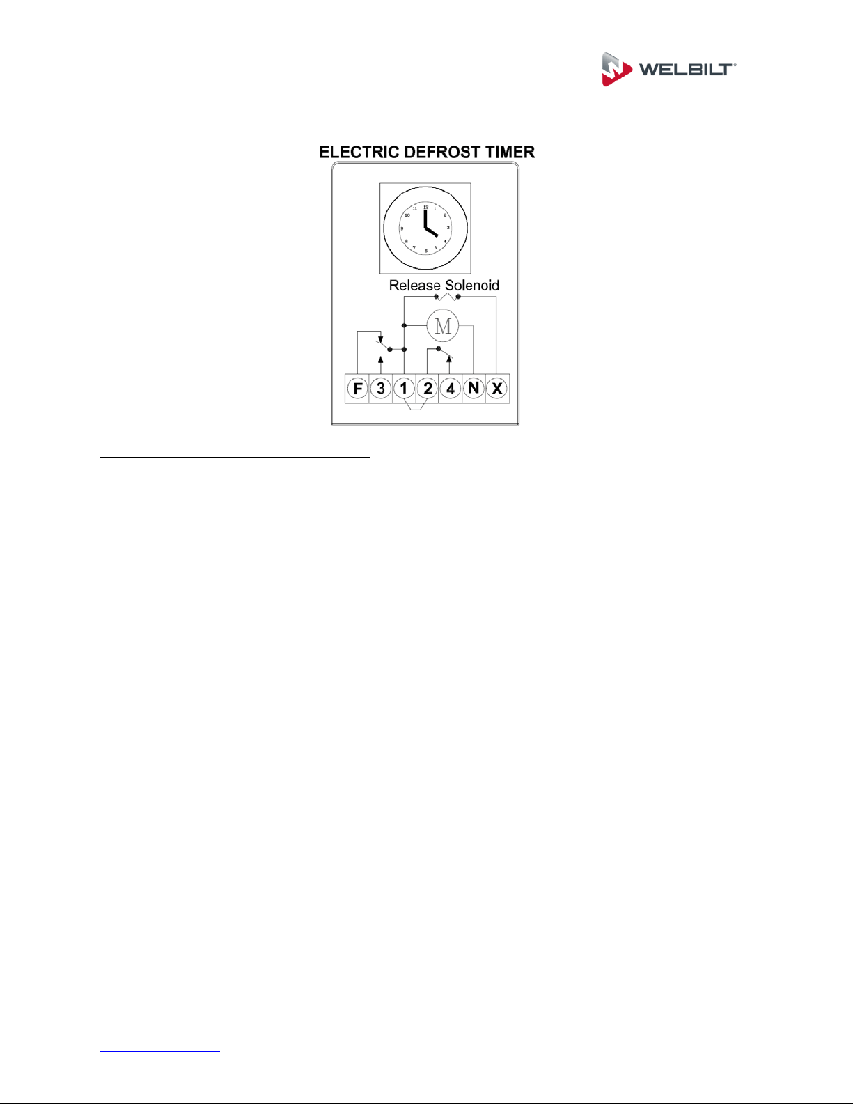
Electric Defrost Timer:
Electric Defrost Time Clock Instructions:
Instructions for setting the timer is located on the inside cover of the time clock. The defrost
timer clock must be set to the correct time at initial start-up and after any power interruptions.
Set the clock by rotating the clock face until the correct time is at the arrow on the face of the
timer.
The switch is programmed by pushing the captive trippers to the inner ring for the entire
period the load is to be turned “ON”. When a tripper is pushed to the outside, the switch is in the
“DEFROST” position. Each defrost tripper represents 15 minutes of defrost time. The timer is
factory set for four defrost cycles daily: 4:00AM, 10:00AM, 4:00PM, and 10:00PM. Each defrost
cycle is programmed for 45 minutes duration. The defrost times may be changed to initiate at
periods of low activity (trippers pushed out will close contacts to terminals 1 & 3).
Note: If the defrost termination thermostat fails to close, the fail safe setting on the timer
will terminate the defrost cycle. The timer starts the defrost cycle automatically at the
predetermined times. A setting of two to four defrost cycles per day is typical. For
heavier frost loads, additional cycles may be required.
When the defrost cycle begins:
1. Switch 2 to 4 opens in the time clock, breaking the circuit to the room thermostat, liquid line
solenoid, and evaporator fan motors. This allows the compressor to pump down and shut
off. Simultaneously, switch 1 to 3 closes in the timer, energizing the defrost heaters.
2. The heaters increase the coil temperatures above 32°F, melting the frost off the coil.
3. When the coil warms to approximately 55°F, the defrost termination thermostat closes and
energizes the switching solenoid in the timer. At this time, switch 1 to 3 in the timer opens,
terminating the defrost heaters. Simultaneously, switch 2 to 4 closes in the time clock,
energizing the temperature control circuit.
4. Suction pressure rises, the low pressure control closes, and the compressor starts.
5. The fan relay closes when the coil temperature reaches approximately 30°F. This energizes
the fan motors.
6. The system operates in the refrigeration cycle until another defrost cycle is initiated by the
timer.
Loading ...
Loading ...
Loading ...