
MODEL: V404-T, V484-T, V554-T
Large Format Display
User’s Manual
MultiSync V404-T
MultiSync V484-T
MultiSync V554-T
Please find your model name in the label on the rear side of the monitor.

Index
DECLARATION OF CONFORMITY....................................................................................................................... English-1
Important Information ............................................................................................................................................. English-2
WARNING ............................................................................................................................................... English-2
CAUTION ................................................................................................................................................ English-2
Safety Precautions, Maintenance & Recommended Use ...................................................................................... English-3
Safety Precautions and Maintenance ...................................................................................................... English-3
Recommended Use ................................................................................................................................. English-3
Ergonomics .............................................................................................................................................. English-3
Cleaning the LCD Panel .......................................................................................................................... English-4
Cleaning the Cabinet ............................................................................................................................... English-4
Installation .............................................................................................................................................................. English-5
Attaching Mounting Accessories .............................................................................................................. English-7
Parts Name and Functions .................................................................................................................................... English-9
Control Panel ........................................................................................................................................... English-9
Terminal Panel ......................................................................................................................................... English-10
Wireless Remote Control ......................................................................................................................... English-12
Operating Range for the Remote Control ................................................................................................ English-13
Setup ...................................................................................................................................................................... English-14
Connections ........................................................................................................................................................... English-16
Wiring Diagram ........................................................................................................................................ English-16
Connecting a Personal Computer ........................................................................................................... English-17
Connecting a Player or Computer with HDMI .......................................................................................... English-17
Connecting a Computer with DisplayPort ................................................................................................ English-17
Connecting a USB device ........................................................................................................................ English-18
For using Touch Panel ............................................................................................................................. English-18
Basic Operation ..................................................................................................................................................... English-19
Power ON and OFF Modes ..................................................................................................................... English-19
Power Indicator ........................................................................................................................................ English-20
Using Power Management ...................................................................................................................... English-20
Aspect ...................................................................................................................................................... English-20
Media Player ............................................................................................................................................ English-21
Displayable/playable files ........................................................................................................................ English-21
File display screen ................................................................................................................................... English-23
Slideshow display .................................................................................................................................... English-24
Media Player settings .............................................................................................................................. English-24
NETWORK & OTHER SETTINGS .......................................................................................................... English-25
Using SHARED SD card SETTINGS ...................................................................................................... English-26
Using CONTENTS COPY ....................................................................................................................... English-27
Using Emergency contents ...................................................................................................................... English-27
Information OSD ...................................................................................................................................... English-27
Picture Mode ........................................................................................................................................... English-28
OSD (On-Screen-Display) Controls ....................................................................................................................... English-31
INPUT ...................................................................................................................................................... English-32
PICTURE ................................................................................................................................................. English-32
AUDIO ..................................................................................................................................................... English-34
SCHEDULE ............................................................................................................................................. English-35
MULTI INPUT .......................................................................................................................................... English-36
OSD ......................................................................................................................................................... English-38
MULTI DISPLAY ...................................................................................................................................... English-38
DISPLAY PROTECTION ......................................................................................................................... English-40
CONTROL ............................................................................................................................................... English-40
OPTION ................................................................................................................................................... English-43
SYSTEM .................................................................................................................................................. English-44
COMPUTE MODULE .............................................................................................................................. English-44
Remote Control Functions ...................................................................................................................................... English-46
Multiple Monitors Connection ................................................................................................................................. English-47
Controlling the LCD monitor via RS-232C Remote Control ................................................................................... English-48
Controlling the LCD monitor via LAN Control .......................................................................................................... English-50
Connecting to a Network ......................................................................................................................... English-50
Network Setting by Using an HTTP Browser ........................................................................................... English-50
POINT ZOOM ........................................................................................................................................................ English-58
PROOF OF PLAY .................................................................................................................................................. English-59
INTELLIGENT WIRELESS DATA .......................................................................................................................... English-60
PIP (Picture in Picture) matrix ................................................................................................................................ English-60
Video out ................................................................................................................................................................ English-61
Features ................................................................................................................................................................. English-62
Troubleshooting ..................................................................................................................................................... English-63
Specifications - V404-T .......................................................................................................................................... English-65
Specifications - V484-T .......................................................................................................................................... English-66
Specifications - V554-T .......................................................................................................................................... English-67
Manufacturer’s Recycling and Energy Information ................................................................................................ English-68
[Notice] About the MPEG-4 AVC, MPEG-4 Visual license included in this product ............................................... English-70
English-1
English
DECLARATION OF CONFORMITY
This device complies with Part 15 of FCC Rules. Operation is subject to the following two conditions. (1) This device may not cause
harmful interference, and (2) this device must accept any interference received, including interference that may cause undesired
operation.
U.S. Responsible Party: NEC Display Solutions of America, Inc.
Address: 500 Park Boulevard, Suite 1100
Itasca, Illinois 60143
Tel. No.: (630) 467-3000
Type of Product: Display Monitor
Equipment Classification: Class B Peripheral
Model: MultiSync V404-T (V404-T)
MultiSync V484-T (V484-T)
MultiSync V554-T (V554-T)
We hereby declare that the equipment specied above
conforms to the technical standards as specied in the FCC Rules.
Cable information
CAUTION: Use the provided specified cables with this color monitor so as not to interfere with radio and television reception.
For mini D-Sub 15-pin, DVI, and USB please use a shielded signal cable with ferrite core.
For HDMI, DisplayPort, D-Sub 9-pin and AUDIO, please use a shielded signal cable. Use of other cables and adapters
may cause interference with radio and television reception.
FCC Information
WARNING: The Federal Communications Commission does not allow any modifications or changes to the unit EXCEPT those
specified by NEC Display Solutions of America, Inc. in this manual. Failure to comply with this government regulation could void your
right to operate this equipment.
1. Please use the supplied power cord or equivalent to ensure FCC compliance.
2. This equipment has been tested and found to comply with the limits for a Class B digital device, pursuant to part 15 of the FCC Rules.
These limits are designed to provide reasonable protection against harmful interference in a residential installation. This equipment
generates, uses and can radiate radio frequency energy, and, if not installed and used in accordance with the instructions, may
cause harmful interference to radio communications. However, there is no guarantee that interference will not occur in a particular
installation. If this equipment does cause harmful interference to radio or television reception, which can be determined by turning the
equipment off and on, the user is encouraged to try to correct the interference by one or more of the following measures:
•Reorientorrelocatethereceivingantenna.
•Increasetheseparationbetweentheequipmentandreceiver.
•Connecttheequipmentintoanoutletonacircuitdifferentfromthattowhichthereceiverisconnected.
•Consultthedealeroranexperiencedradio/TVtechnicianforhelp.
If necessary, the user should contact the dealer or an experienced radio/television technician for additional suggestions.
The user may find the following booklet, prepared by the Federal Communications Commission, helpful: “How to Identify and
Resolve Radio-TV Interference Problems.” This booklet is available from the U.S. Government Printing Office, Washington, D.C.,
20402, Stock No. 004-000-00345-4.
Windows is a registered trademark of Microsoft Corporation.
NEC is a registered trademark of NEC Corporation.
MultiSync is a trademark or registered trademark of NEC Display Solutions, Ltd. in Japan and other countries.
DisplayPort and DisplayPort Compliance Logo are trademarks owned by Video Electronics Standards
Association in the United States and other countries.
All other brands and product names are trademarks or registered trademarks of their respective owners.
The terms HDMI and HDMI High-Definition Multimedia Interface, and the HDMI Logo are trademarks
or registered trademarks of HDMI Licensing Administrator, Inc. in the United States and other countries.
Trademark PJLink is a trademark applied for trademark rights in Japan, the United States of America and
other countries and areas.
microSD and microSD SDHC logos are trademarks of SD-3C, LLC.
CRESTRON and CRESTRON ROOMVIEW are trademarks or registered trademarks of
Crestron Electronics, Inc. in the United States and other countries.
Raspberry Pi is a trademark of the Raspberry Pi Foundation.
GPL/LGPL Software Licenses
The product includes software licensed under GNU General Public License (GPL), GNU Lesser General Public License (LGPL),
and others.
For more information on each software, see “readme.pdf” inside the “about GPL&LGPL” folder on the supplied CD-ROM.
Adobe and the Adobe logo are either registered trademarks or trademarks of Adobe Systems Incorporated in the United States and/or
other countries.
English-2
Important Information
WARNING
TO PREVENT FIRE OR SHOCK HAZARDS, DO NOT EXPOSE THIS UNIT TO RAIN OR MOISTURE. ALSO, DO NOT
USE THIS UNIT’S POLARIZED PLUG WITH AN EXTENSION CORD RECEPTACLE OR OTHER OUTLETS UNLESS THE
PRONGS CAN BE FULLY INSERTED.
REFRAIN FROM OPENING THE CABINET AS THERE ARE HIGH VOLTAGE COMPONENTS INSIDE. REFER SERVICING
TO QUALIFIED SERVICE PERSONNEL.
CAUTION
TO REDUCE THE RISK OF ELECTRIC SHOCK, MAKE SURE POWER CORD IS UNPLUGGED FROM WALL SOCKET. TO
FULLY DISENGAGE THE POWER TO THE UNIT, PLEASE DISCONNECT THE POWER CORD FROM THE AC OUTLET.
DO NOT REMOVE COVER (OR BACK). NO USER SERVICEABLE PARTS INSIDE. REFER SERVICING TO QUALIFIED
SERVICE PERSONNEL.
This symbol warns user that uninsulated voltage within the unit may have sufficient magnitude to cause electric
shock. Therefore, it is dangerous to make any kind of contact with any part inside this unit.
This symbol alerts the user that important literature concerning the operation and maintenance of this unit has been
included. Therefore, it should be read carefully in order to avoid any problems.
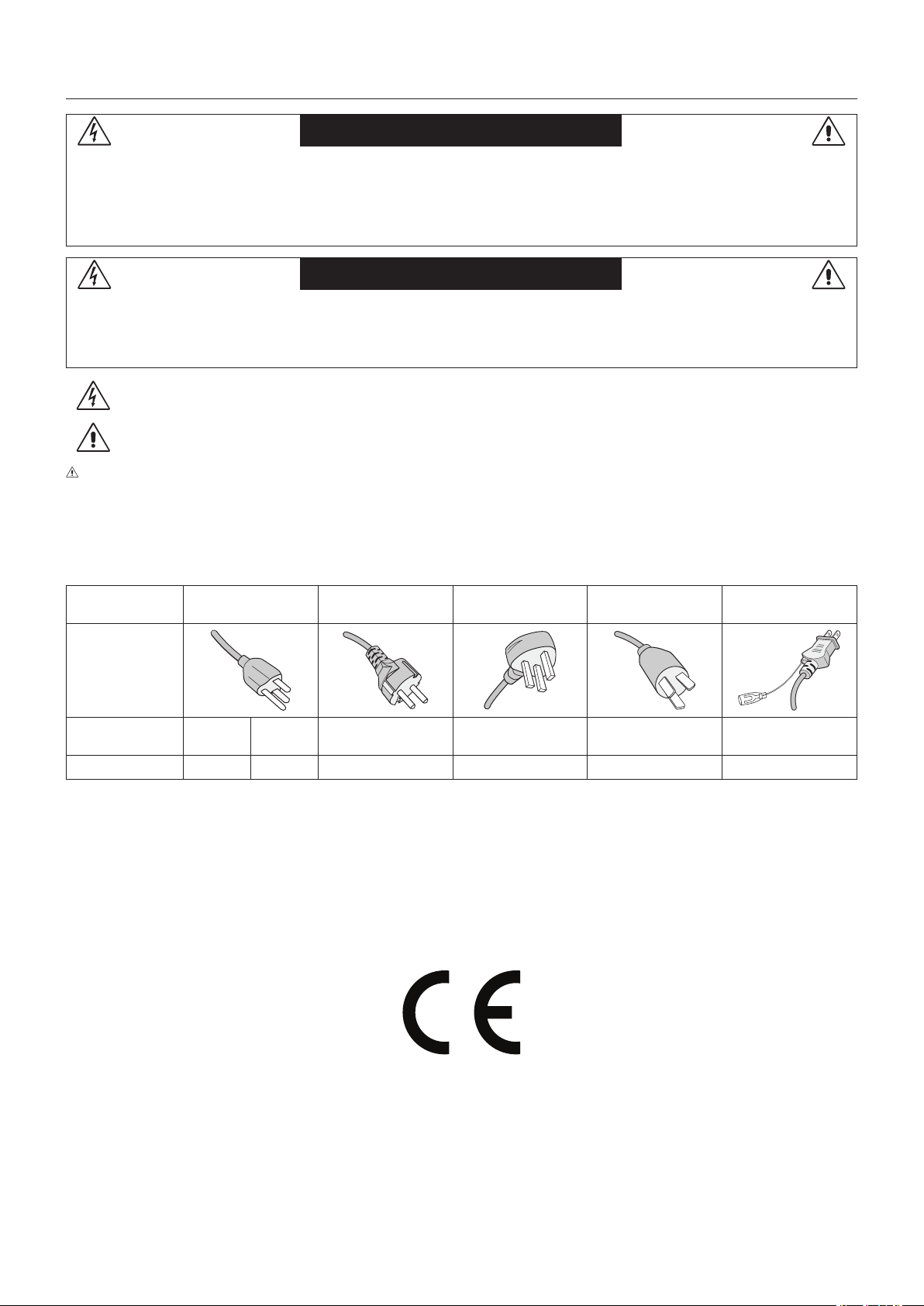
CAUTION: Please use the power cord provided with this display in accordance with the table below. If a power cord is
not supplied with this equipment, please contact NEC. For all other cases, please use the power cord with the plug style that
matches the power socket where the monitor is located. The compatible power cord corresponds to the AC voltage of the power
outlet and has been approved by, and complies with, the safety standards in the country of purchase.
This equipment is designed to be used in the condition of the power cord connected to earth. If the power cord is not connected
to the earth, it may cause electric shock. Please make sure the power cord is earthed properly.
Plug Type North America
European
Continental
U.K. Chinese Japanese
Plug Shape
Region
U.S.A./
Canada
Taiwan
EU U.K. China Japan
Voltage
120*
110
230 230 220 100
* When operating this monitor with its AC 125-240V power supply, use a power supply cord that matches the power supply
voltage of the AC power outlet being used.
NOTE: This product can only be serviced in the country where it was purchased.
Use the power cord which has BSMI mark at both ends when you use this monitor in Taiwan.
•TheintendedprimaryuseofthisproductisasanInformationTechnicalEquipmentinanofceordomesticenvironment.
•Theproductisintendedtobeconnectedtoacomputerandisnotintendedforthedisplayoftelevisionbroadcastsignals.

English-3
English
Safety Precautions and Maintenance
FOR OPTIMUM PERFORMANCE, PLEASE NOTE THE
FOLLOWING WHEN SETTING UP AND USING
THE MULTI-FUNCTION MONITOR:
•DO NOT OPEN THE MONITOR. There are no user
serviceable parts inside and opening or removing covers
may expose you to dangerous shock hazards or other
risks. Refer all servicing to qualified service personnel.
•Donotbend,crimporotherwisedamagethepowercord.
•Donotplaceanyheavyobjectsonthepowercord.
Damage to the cord may cause shock or fire.
•Thepowersupplycordyouusemusthavebeen
approved by and comply with the safety standards of your
country. (e.g. Type H05VV-F 3G 0.75 mm
2
should be used
in Europe).
•IntheUKuseaBS-approvedpowercordwithamolded
plug having a black (5 A) fuse installed for use with this
monitor.
•Thepowercableconnectoristheprimarymeansof
detaching the system from the power supply. The monitor
should be installed close to a power outlet, which is easily
accessible.
•Donotspillanyliquidsintothecabinetoruseyour
monitor near water.
•Donotinsertobjectsofanykindintothecabinetslots,
as they may touch dangerous voltage points, which can
be harmful or fatal, or may cause electric shock, fire or
equipment failure.
•Donotplacethisproductonaslopingorunstablecart,
stand or table, as the monitor may fall, causing serious
damage to the monitor.
•Donotmountthisproductupsidedownforanextended
period of time as it may cause permanent damage to the
screen.
•Donotusethemonitoroutdoors.
•Ifglassisbroken,handlewithcare.
•Temperature controlled fans are implemented in this
monitor. For reliable performance and long useful life of
this product, it is mandatory to not cover any vents on the
monitor.
•Ifmonitororglassisbroken,donotcomeincontactwith
the liquid crystal and handle with care.
•Allowadequateventilationaroundthemonitor,sothat
heat can properly dissipate.
•Donotblockventilatedopeningsorplacethemonitor
near a radiator or other heat sources.
•Donotputanythingontopofthemonitor.
•Handlewithcarewhentransporting.Savepackagingfor
transporting.
•Ifusingthecoolingfancontinuously,itisrecommendedto
wipe holes clean a minimum of once a month.
•To ensure the monitor’s reliability, please clean the holes
at the rear side of the cabinet at least once a year to
remove dirt and dust.
•WhenusingaLANcable,donotconnecttoaperipheral
device with wiring that might have excessive voltage.
•Donotusethemonitorinhightemperature,humid,dusty,
or oily areas.
•Donotusemonitorunderrapidtemperatureandhumidity
change condition and avoid cold air from air-conditioning
outlet directly, as it may shorten the lifetime of the monitor
or cause condensation. If condensation of water has
happened, let the monitor stand unplugged until the
condensation has disappeared.
•Thetouchpanelglassisnotsafetyglassandisnot
laminated. As with other glass, the touch panel glass may
break into sharp pieces if misused, dropped, or otherwise
subjected to a substantial shock. If touch panel glass
happens to break, please use care to avoid injury.
•DONOTtapthemonitorwithhardorpointedobject,such
as a pen, or pencil.
Connecting to a TV*
•Cabledistributionsystemshouldbegrounded(earthed)
in accordance with ANSI/NFPA 70, the National Electrical
Code (NEC), in particular Section 820.93, Grounding of
Outer Conductive Shield of a Coaxial Cable.
•Thescreenofthecoaxialcableisintendedtobe
connected to earth in the building installation.
Under the following conditions immediately disconnect your
monitor from the wall outlet and refer servicing to qualified
service personnel:
•Ifthepowersupplycordorplugisdamaged.
•Ifliquidhasspilled,orobjectshavefallenintothemonitor.
•Ifthemonitorhasbeenexposedtorainorwater.
•Ifthemonitorhasbeendroppedorthecabinethasbeen
damaged.
•Ifyounoticeanystructuraldamagesuchascracksor
unnatural wobbling.
•Ifthemonitordoesnotoperatenormallybyfollowing
operating instructions.
Recommended Use
Ergonomics
To realize the maximum ergonomic benefits, we recommend
the following:
•Forthemonitor’soptimumperformance,allow20minutes
for warming up. Avoid reproduction of still patterns on
the monitor for long periods of time to avoid image
persistence (after image effects).
•Restyoureyesperiodicallybyfocusingonanobjectat
least 5 feet away. Blink often.
•Positionthemonitorata90°angletowindowsandother
light sources to minimize glare and reflections.
•Adjustthemonitor’sbrightness,contrastandsharpness
controls to enhance readability.
•Getregulareyecheckups.
•UsethepresetSizeandPositioncontrolswithstandard
signals.
•UsethepresetColorSetting.
•Usenon-interlacedsignals.
•Donotuseprimarycolorblueonadarkbackground,as
it is difficult to see and may produce eye fatigue due to
insufficient contrast.
•Suitable for entertainment purposes at controlled
luminous environments, to avoid disturbing reflections
from the screen.
Safety Precautions, Maintenance & Recommended Use
* The product you purchased may not have this feature.

English-4
Cleaning the LCD Panel
•WhentheLCDpanelisdusty,pleasegentlywipewitha
soft cloth.
•CleantheLCDmonitorsurfacewithalint-free,non-
abrasive cloth. Avoid using any cleaning solution or glass
cleaner!
•PleasedonotrubtheLCDpanelwithhardmaterial.
•PleasedonotapplypressuretotheLCDpanelsurface.
•PleasedonotuseOAcleanerasitwillcause
deterioration or discoloration on the LCD panel surface.
Cleaning the Cabinet
•Unplugthepowersupply
•Gentlywipethecabinetwithasoftcloth
•Tocleanthecabinet,dampentheclothwithaneutral
detergent and water, wipe the cabinet and follow with a
dry cloth.
NOTE: DO NOT clean with benzene thinner, alkaline
detergent, alcoholic system detergent, glass
cleaner, wax, polish cleaner, soap powder, or
insecticide. Rubber or vinyl should not be in
contact with the cabinet for an extended period
of time. These types of fluids and materials can
cause the paint to deteriorate, crack or peel.
English-5
English
For box contents, please refer to the printed contents sheet
provided in the box.
This device cannot be used or installed without the Tabletop
Stand or other mounting accessory for support. For proper
installation it is strongly recommended to use a trained,
NEC authorized service person. Failure to follow NEC
standard mounting procedures could result in damage to the
equipment or injury to the user or installer. Product warranty
does not cover damage caused by improper installation.
Failure to follow these recommendations could result in
voiding the warranty.
Mounting
CAUTION
DO NOT mount the monitor yourself. Please ask your
supplier. For proper installation it is strongly recommended to
use a trained, qualified technician. Please inspect the location
where the unit is to be mounted. Mounting on wall or ceiling
is the customer’s responsibility. Not all walls or ceilings are
capable of supporting the weight of the unit. Product warranty
does not cover damage caused by improper installation, re-
modeling, or natural disasters. Failure to comply with these
recommendations could result in voiding the warranty.
DO NOT block ventilated openings with mounting
accessories or other accessories.
For NEC Qualified Personnel:
To ensure safe installation, use two or more brackets to
mount the unit. Mount the unit to at least two points on the
installation location.
Please note the following when mounting
on wall or ceiling
CAUTION
•Whenusingmountingaccessoriesotherthanthosethat
are NEC approved, they must comply with the VESA-
compatible (FDMlv1) mounting method.
•NECrecommendsmountinginterfacesthatcomplywith
UL1678 standard in North America.
•NECstronglyrecommends
using size M6 screws
(10-12 mm + thickness
of bracket and washers in
length). If using screws
longer than 10-12 mm,
check the depth of the hole.
(Recommended Fasten
Force:470-635N•cm).Bracket
hole should be under 8.5 mm.
•Priortomounting,inspecttheinstallationlocationto
ensure that it is strong enough to support the weight of
the unit so that the unit will be safe from harm.
•For detailed information, refer to the instructions included
with the mounting equipment.
Make sure that there is no gap between the monitor and the
bracket.
When used in a video wall configuration for a longer
time, slight expansion of the monitors may happen due to
temperature changes. Due to this it is recommended that
over one millimeter gap is kept between adjacent monitor
edges.
CAUTION:•Wheninstalling,donotapplypressureto
the screen or excessive force to any part of
the monitor by pushing or leaning on it.
This may cause the monitor to become
distorted or damaged.
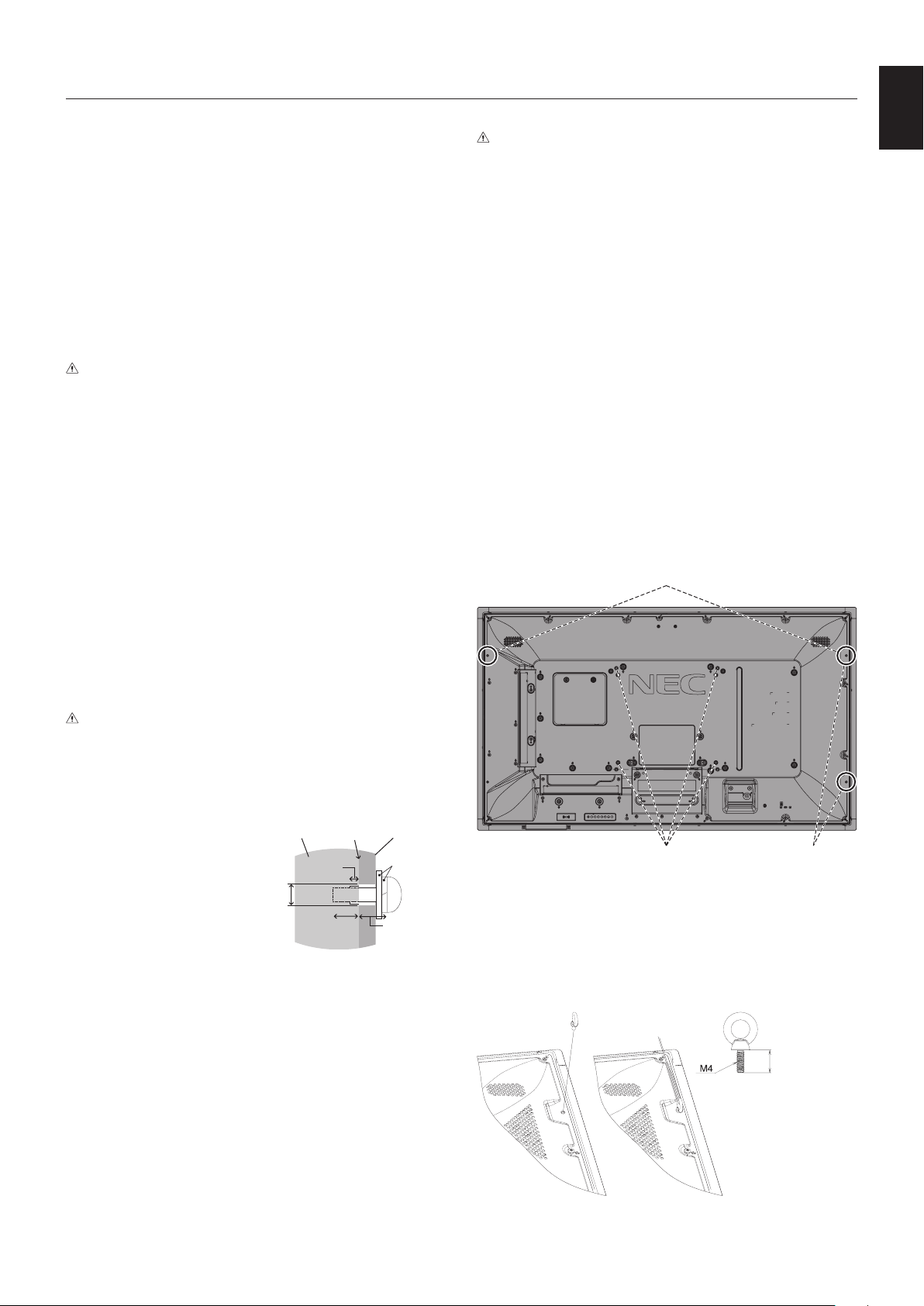
•To prevent the LCD monitor from falling
off from the wall or ceiling, NEC strongly
recommends using a wire.
•Please install LCD monitor in a spot of the
wall or ceiling strong enough to support the
monitor.
•Prepare the LCD monitor using mounting
accessories such as hook, eyebolt or
mounting parts and then secure the LCD
monitor with a wire. The installed wire must
not be tight.
•Donotattempttohangthemonitorusing
an installation safety wire. The monitor
must be properly installed on a VESA
compatible mount.
•Please make sure the mounting
accessories are strong enough to support
the LCD monitor before mounting it.
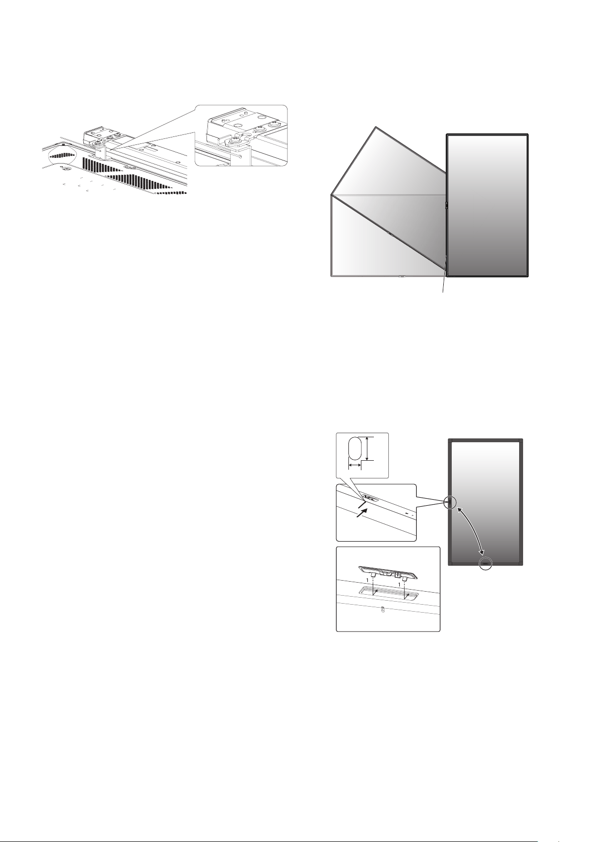
Please use the two optional speaker mounting holes.
(RecommendedFastenForce:139-189N•cm).
Landscape installation for safety wire
Portrait installation for
safety position
VESA Mounting Interface (M6)
Installing a wire to a monitor with no speakers installed
Please use eyebolts to install a wire to the monitor.
To prevent the LCD monitor from falling off from the wall or
ceiling, NEC strongly recommends using a wire.
Please install LCD monitor in a spot of the wall or ceiling
strong enough to support the monitor.
Less than 12 mm
Installation
Screw
Unit
10-12 mm
Thickness
of bracket
and washers
under
8.5 mm
No gap
Washers
Mounting
Bracket
No thread
4 mm
English-6
Installing a wire to a monitor with installed speakers
(Landscape position only)
Please use speaker mounting parts to install a wire to the
monitor.
Optional speaker is installed on the rear of the LCD monitor:
Mounting location
•Theceilingandwallmustbestrongenoughtosupportthe
monitor and mounting accessories.
•DONOTinstallinlocationswhereadoororgatecanhit
the unit.
•DONOTinstallinareaswheretheunitwillbesubjected
to strong vibrations and dust.
•DO NOT install the monitor next to a location where the
main power supply is fed into the building.
•DO NOT install the monitor in a location where people
can easily grab and hang onto the unit or the mounting
equipment.
•Allow for adequate ventilation or provide air conditioning
around the monitor, so that heat can properly dissipate
away from the monitor and from the mounting equipment.
Mounting on ceilings
•Ensurethattheceilingissturdyenoughtosupportthe
weight of the unit and the mounting equipment over time,
against earthquakes, unexpected vibrations, and other
external forces.
•Besuretheunitismountedtoasolidstructurewithin
the ceiling, such as a support beam. Secure the monitor
using bolts, spring lock washers, washer and nut.
•DONOTmounttoareasthathavenosupportinginternal
structure. DO NOT use wood screws or anchor screws for
mounting. DO NOT mount the unit to ceiling or to hanging
fixtures.
Maintenance
•Periodicallycheckforloosescrews,gaps,distortions,
or other problems that may occur with the mounting
equipment. If a problem is detected, please refer to
qualified personnel for service.
•Regularlycheckthemountinglocationforsignsof
damage or weakness that may occur over time.
Orientation
•Whenusingthemonitorintheportraitposition,itshould
be rotated clockwise so that the left side is moved to
the top, right side is moved to the bottom. This will allow
for proper ventilation and will extend the lifetime of the
monitor. Improper ventilation may shorten the lifetime of
the monitor.
LED Indicator
Changing NEC logo ornament position
When using the monitor in the portrait position, the NEC logo
ornament position can be changed.
Removing the logo ornament: Insert a thin stick (less than
3 mm diameter) into the hole in the bottom of logo ornament
and remove the logo ornament by pushing up it from the
bottom.
Attaching the logo ornament: Hook the part (1) of logo
ornament into the bezel and press in.
2 mm
3.6 mm
English-7
English
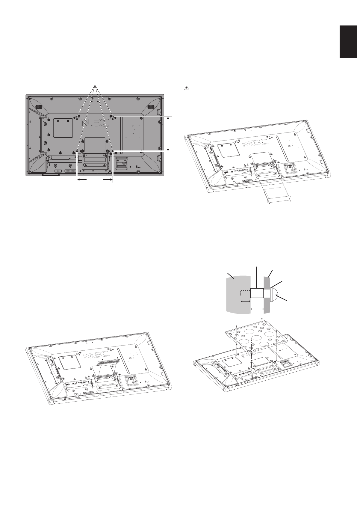
Attaching Mounting Accessories
The monitor is designed for use with the VESA mounting
system.
1. Attach Mounting Accessories
Be careful to avoid tipping the monitor when attaching
accessories.
VESA Mounting Interface (M6)
300 mm
300 mm
Mounting accessories can be attached with the monitor in
the face down position. To avoid scratching the LCD panel,
always place a soft cloth, such as a blanket that is larger
than the monitor’s screen area, on the table before laying the
monitor face down. Make sure there is nothing on the table
that can damage the monitor.
When using mounting accessories other than NEC compliant
and approved, they must comply with the VESA Flat Display
Mounting Interface Standard (FDMI).
NOTE: Prior to installation, be sure to place the monitor
on a flat area with adequate space.
2. Using an Option Board
1. Turn off the main power switch.
2. Place the monitor face down on the soft cloth.
NOTE: Be sure to place the monitor on a flat and adequate
space.
3. Remove the attached slot cover by unscrewing the
installed screws (Figure 1).
Figure 1
4. Insert the option board into the monitor and fix it with the
removed screws (Figure 2).
NOTE: Please contact your supplier for available option
boards.
Do not apply excessive force to manipulate the
option board before fixing it with screws.
Make sure that the board is inserted into the slot in
the correct orientation.
CAUTION: Ensure the option board is attached by the
removed screws. As falling the option board
may expose you to danger.
(RecommendedFastenForce:139-189N•cm).
Figure 2
3. Using Wall Mount Adapter
If the mounting accessory interferes with ventilation hole, use
the included wall mount adaptors (Dia. 14 mm) and screws.
If the adaptor screws are too long, include a washer to
reduce the depth. Washer not included.
Wall mount
adapter screw
Washer
Mounting bracket
Unit
Wall mount adapter (Dia. 14 mm)
10-12 mm
18 mm
Pictured mounting solutions may not be available in some
countries.
English-8
4. Installing and removing the optional
table top stand
CAUTION: Installing and removing the stand must be
done by two or more people.
For installation follow the instructions included with the
stand or mounting equipment. Use only those devices
recommended by the manufacturer.
NOTE: ONLY use screws which are supplied with the
optional table top stand.
When installing the LCD monitor stand, handle the unit with
care to avoid pinching your fingers.
NOTE: Use the ST-401. Please refer to the ST-401
user’s manual for more detail.
NOTE: DO NOT use the monitor on the floor with the table
top stand. Please use this monitor on a table or
with a mounting accessory for support.
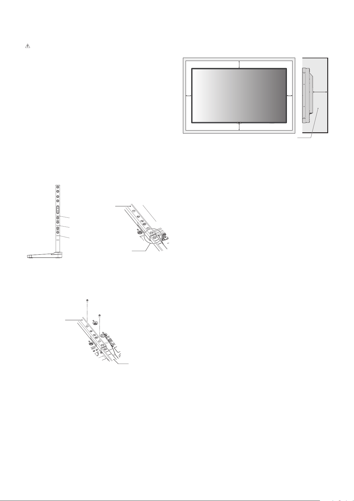
Height adjustment
1. The lines on the stand pole are indicators of the height
adjustment (Figure 3). Please adjust the pipe to the lines.
Figure 3
V554-T
V484-T
V404-T
Pipe
Adjust the pipe to a line.
2. Please install the stand pole and the pipe with included
screws. Please screw the two screw holes at the pipe
(Figure 4).
Pipe
Figure 4
Stand pole
NOTE: Installing the monitor at the wrong height can
cause tipping.
Please install your monitor at proper height.
When the monitor is moved after the stands are attached, do
not drag the monitor with the stands in contact with the floor.
It may cause damage to the touch panel function.
5. Ventilation Requirements
When mounting in an enclosed space or recessed area,
leave adequate room between the monitor and the enclosure
to allow heat to disperse, as shown below.
100 mm
100 mm
30 mm
100 mm
100 mm
Must be under 35 Degree Celsius.
Allow adequate ventilation or provide air conditioning around
the monitor, so that heat can properly dissipate away from
the unit and the mounting equipment; especially when you
use monitors in a multiple screen configuration.
NOTE: The sound quality of the internal speakers will be
different depending on the acoustics of the room.
English-9
English
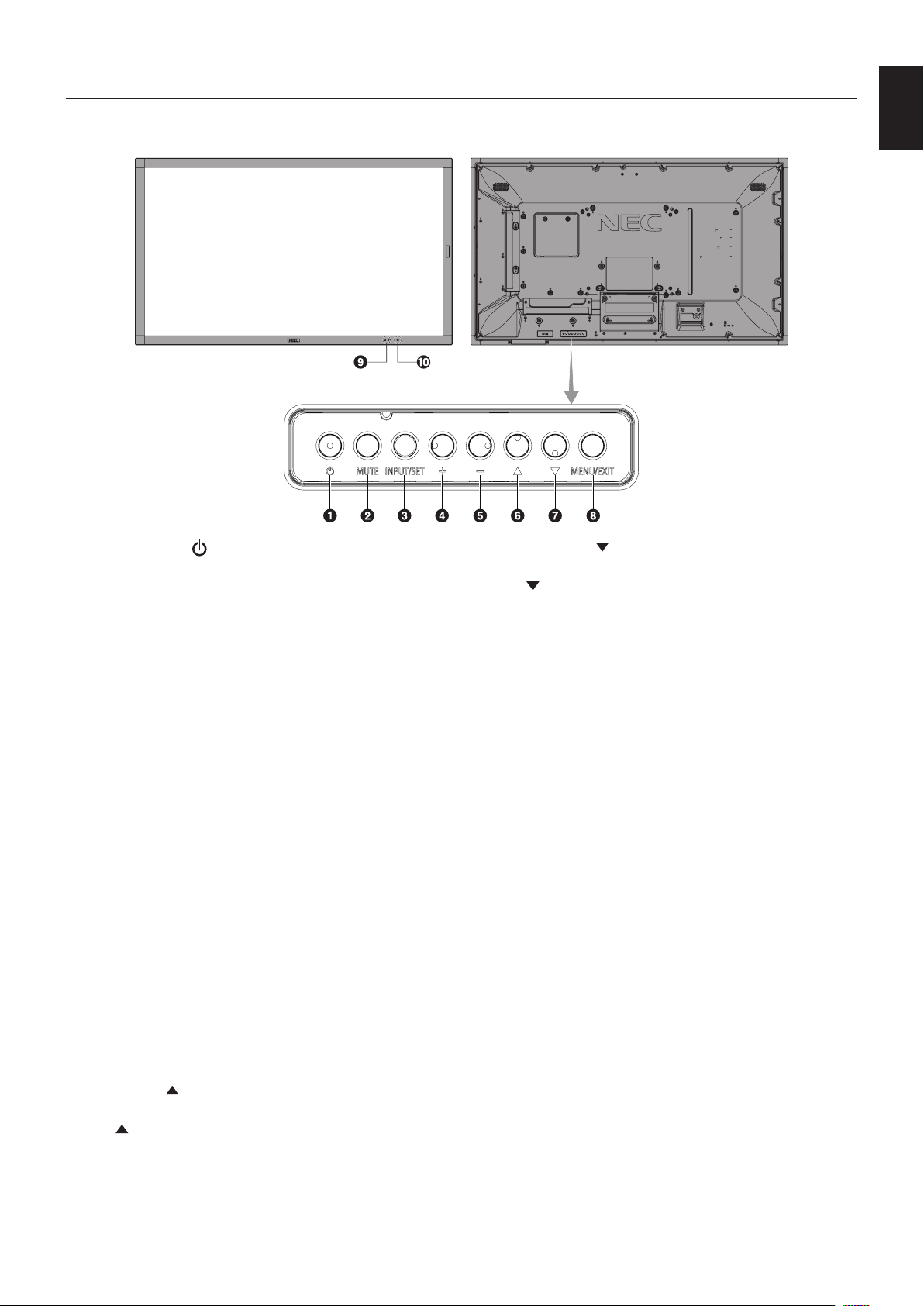
Parts Name and Functions
Control Panel
A Power Button ( )
Switches the power on/standby. See also page 19.
B Mute Button (MUTE)
Switches the audio mute on/off.
C Input/Output Button (INPUT/SET)
INPUT: Toggle switches between below inputs.
[DVI], [HDMI1], [HDMI2], [DisplayPort1], [DisplayPort2],
[VGA (YPbPr/RGB)], [VIDEO], [MP], [OPTION*],
[C MODULE]*
1
. These are available inputs only, shown as
their factory preset name.
SET: When OSD (On Screen Display) is shown, this button
acts as a “set button” when you make a selection.
*: This function depends on which option board you are using.
*
1
: This input is available when the optional Raspberry Pi
Compute Module Interface Board and Raspberry Pi Compute
Module are installed.
D Plus Button (+)
Increases the audio output level when the OSD menu is
turned off.
Acts as (+) button to increase the adjustment within OSD
menu.
E Minus Button (-)
Decreases the audio output level when the OSD menu is
turned off.
Acts as (-) button to decrease the adjustment within OSD
menu.
F Up Button ( )
Activates the OSD menu when the OSD menu is turned off.
Acts as
button to move the highlighted area up to select
adjustment items within the OSD menu.
G Down Button ( )
Activates the OSD menu when the OSD menu is turned off.
Acts as
button to move the highlighted area down to select
adjustment items within the OSD menu.
H Menu/Exit Button (MENU/EXIT)
Activates the OSD menu when the OSD menu is turned off.
Acts as a back button within the OSD to move to the previous
OSD menu.
Acts as an EXIT button to close the OSD when on the main
menu.
I Remote Control Sensor and Power Indicator
Receives the signal from the remote control (when using the
wireless remote control). See also page 13.
Glows blue when the LCD monitor is in active mode*.
Green and Amber blink alternately when the “SCHEDULE
SETTINGS” function is enabled*
1
.
When a component failure is detected within the monitor, the
indicator will blink red or blink a combination of red and blue.
* If “OFF” is selected in the “POWER INDICATOR”
(see page 42), the LED will not glow when the LCD monitor is in
active mode.
*
1
If “OFF” is selected in the “SCHEDULE INDICATOR”
(see page 42), the LED will not blink.
NOTE: Please refer to the POWER INDICATOR (see
page 42
).
J Room Light Sensing Sensor
Detects the level of ambient light, allowing the monitor
to make automatic adjustments to the backlight setting,
resulting in a more comfortable viewing experience. Do not
cover this sensor. See page 42.
English-10
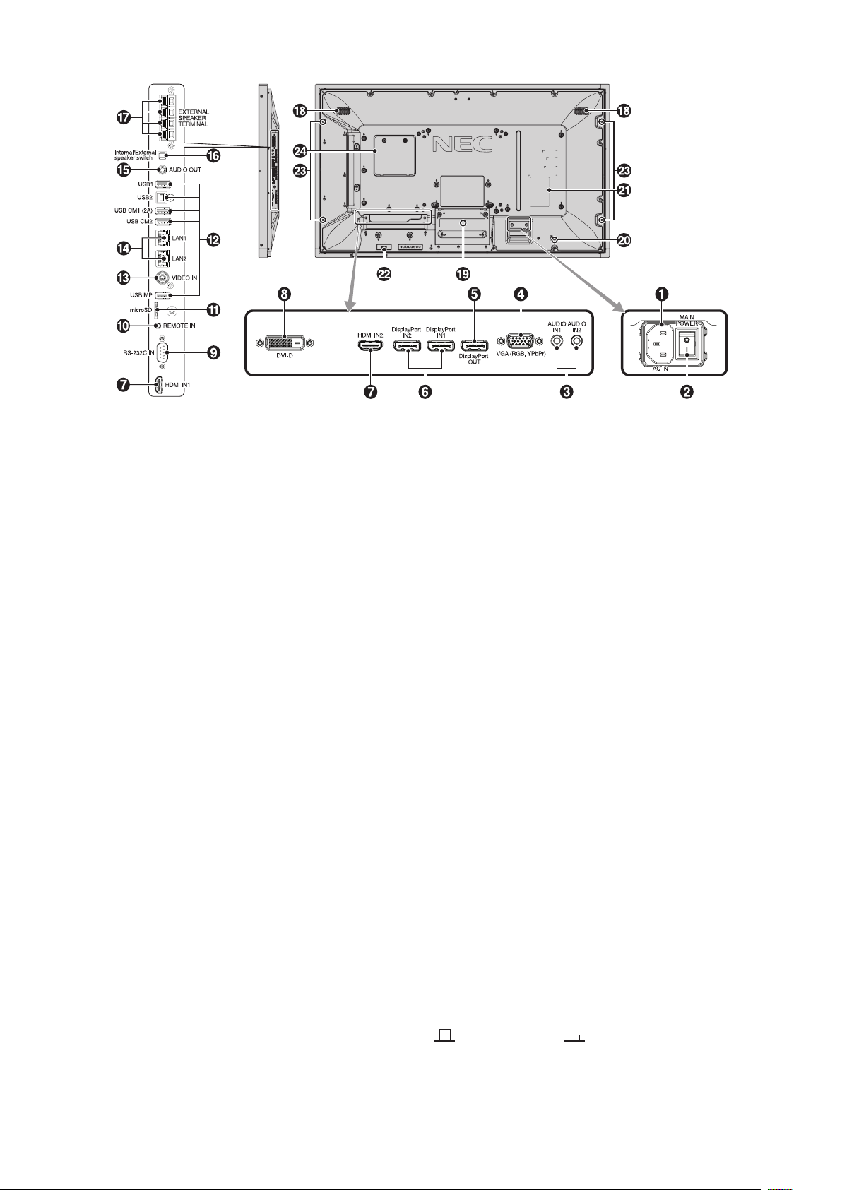
Terminal Panel
USB Upstream
A AC IN Connector
Connects with the supplied power cord.
B Main Power Switch
On/Off switch to turn main power ON/OFF.
C Audio IN1/IN2
Audio signal input from external equipment such as a
computer or player.
D VGA IN (Mini D-Sub 15-pin)
Analog RGB signals input from a personal computer or from
other RGB equipment. This input can be used with an RGB
or YPbPr source. Please select signal type in TERMINAL
SETTINGS. See page 37.
NOTE: When you use this connector for YPbPr, please use a
suitable signal cable. If you have any questions, please ask
your supplier.
E DisplayPort OUT
To output DisplayPort signals.
Outputs DisplayPort1 signal.
F DisplayPort IN1/IN2
DisplayPort signals input.
G HDMI IN1/IN2
Digital HDMI signals input.
H DVI IN (DVI-D)
To input digital RGB signals from a computer or HDTV device
having a digital RGB output.
* This connector does not support analog input.
I RS-232C IN (D-Sub 9 pin)
Connect RS-232C input from external equipment such as a
computer in order to control RS-232C functions.
J Remote IN
Use the optional sensor unit by connecting it to your monitor.
NOTE: Do not use this connector unless specified.
K microSD Card Slot
Insert a microSD memory card. To use the Media player,
please connect a microSD memory card to this port
(See page 22).
To install the microSD card slot cover, please refer to
“Installing microSD card slot cover” (See page 22).
L USB Port
USB1: Downstream port (USB Type-A).
To connect USB devices.
USB2: Upstream port (USB Type-B).
To connect external equipment such as a
computer. To use the touch panel function and
to control the monitor from connected external
equipment, please use this port.
USB CM1 (2A): Power supply port.
USB CM2*: Service port. Please do not connect devices.
* USB functionality is available when the optional Raspberry
Pi Compute Module Interface Board and Raspberry Pi
Compute Module are installed.
USB MP: USB storage device port. This port is for future
software upgrades.
To use the Media player, please connect USB
storage device to this port (See page 18).
MP is an abbreviation of Media Player.
M VIDEO IN (RCA)
Composite video signal input.
N LAN Port 1/2 (RJ-45)
LAN connection. See page 47 and page 50.
NOTE: Please give priority for use to LAN1.
O Audio OUT
Audio signal output from the AUDIO IN1/IN2, DisplayPort and
HDMI to an external device (stereo receiver, amplifier, etc.).
NOTE: This connector is not a Headphone terminal.
P Internal/External Speaker Switch
: Internal speaker : External speaker.
NOTE: Please turn off the monitor’s main power when you
use the Internal/External speaker switch.

English-11
English
Q External Speaker Terminal
To output the audio signal.
Red terminal is plus (+).
Black terminal is minus (-).
NOTE: This speaker terminal is for 15 W + 15 W (8 ohm)
speaker.
R Internal Speaker
S Option Board Slot
Slot 2 type accessory is available. Please contact your
supplier for detailed information.
NOTE: Please contact your supplier for available option board.
T Security Slot
Security and theft protection lock compatible with
Kensington security cables/equipment.
For products, visit Kensington’s website.
Rating Label
Intelligent Wireless Data Sensor
Sensor for wireless communication of monitor for information
and settings.
Option Speaker Mounting Hole
NOTE: Please contact your supplier for available optional
speaker.
Raspberry Pi Compute Module Slot
Slot for installing a Raspberry Pi Compute Module Interface
Board and Raspberry Pi Compute Module. Please refer to
https://www.nec-display.com/dl/en/manual/raspberrypi/
for more information.
CAUTION: Installation must be performed by a qualified
technician. Do not attempt to install a
Compute Module Interface Board and
Raspberry Pi Compute Module by yourself.
English-12
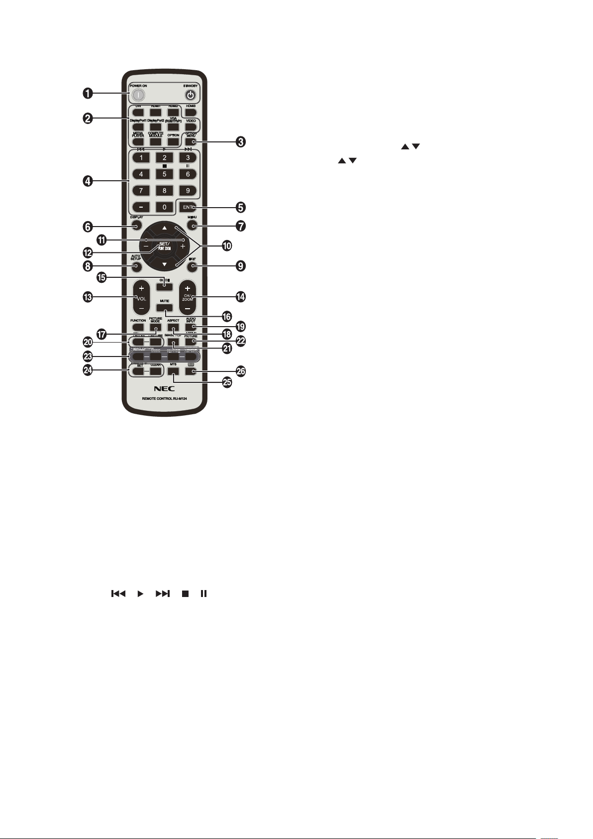
Wireless Remote Control
A POWER ON/STANDBY Button
Switches the power on/standby.
B INPUT Button
Selects the input signal.
Input signal for the MEDIA PLAYER is shown as MP.
C OPTION MENU Button
D KEYPAD
Press the buttons to set and change passwords, change
channel and set REMOTE ID.
Below buttons are used for CEC (Consumer Electronics
Control) (See page 43) and the Media Player function
(See page 21): 1 , 2 , 3 , 5 , 6 .
E ENT Button*
1
Confirm the AUTO PLAY FOLDER in MediaPlayer.
F DISPLAY Button
Turns on/off the information OSD. See page 27.
If you lock remote control buttons using the IR LOCK
SETTINGS function, you can unlock the buttons by holding
down this DISPLAY button for more than 5 seconds.
G MENU Button
Turns on/off the menu mode.
H AUTO SET UP Button
Enters auto setup menu. See page 33.
I EXIT Button
Returns to the previous menu within the OSD menu.
J UP/DOWN Button (
/ )
Acts as button to move the highlighted area up or down
to select adjustment items within the OSD menu.
Small screen which adjusted PIP (picture in picture) mode
moves up or down.
K MINUS/PLUS (-/+) Button
Increases or decreases the adjustment level within the OSD
menu settings.
Small screen which adjusted “PIP” mode moves left or right
and increases or decreases the size.
L SET/POINT ZOOM Button
SET: When OSD is shown, this button acts as “set button”
when you make a selection.
POINT ZOOM: When OSD is not shown, this button acts as
“point zoom button”.
M VOLUME UP/DOWN Button (VOL +/-)
Increases or decreases the audio output level.
N CH/ZOOM UP/DOWN Button (CH/ZOOM +/-)*
1
Increases or decreases the POINT ZOOM level.
Please refer to POINT ZOOM (See page 58).
O GUIDE Button*
1
P MUTE Button
Turns on/off the mute function.
Q PICTURE MODE Button
Selects the picture mode, [HIGHBRIGHT], [STANDARD],
[sRGB], [CINEMA], [CUSTOM1], [CUSTOM2],
[SVE-(1-5) SETTINGS]. See page 30.
HIGHBRIGHT: For moving images such as DVD.
STANDARD: For images.
sRGB: For text based images.
CINEMA: For movies.
CUSTOM1 and CUSTOM2: Custom setting.
SVE-(1-5) SETTINGS: For images and movies.
R ASPECT Button
Selects the picture aspect, [FULL], [WIDE]*, [DYNAMIC]*,
[1:1], [ZOOM] and [NORMAL]. See page 20.
* HDMI1, HDMI2, VGA (YPbPr) inputs only.
S AUDIO INPUT Button
Selects the audio input source [IN1], [IN2], [HDMI1],
[HDMI2], [DisplayPort1], [DisplayPort2], [OPTION]*
1
, [MP],
[C MODULE]*
2
.
*1: This button’s action depends on which option board you are using.
*2: This input is available when the optional Raspberry Pi Compute Module
Interface Board and Raspberry Pi Compute Module are installed.
English-13
English
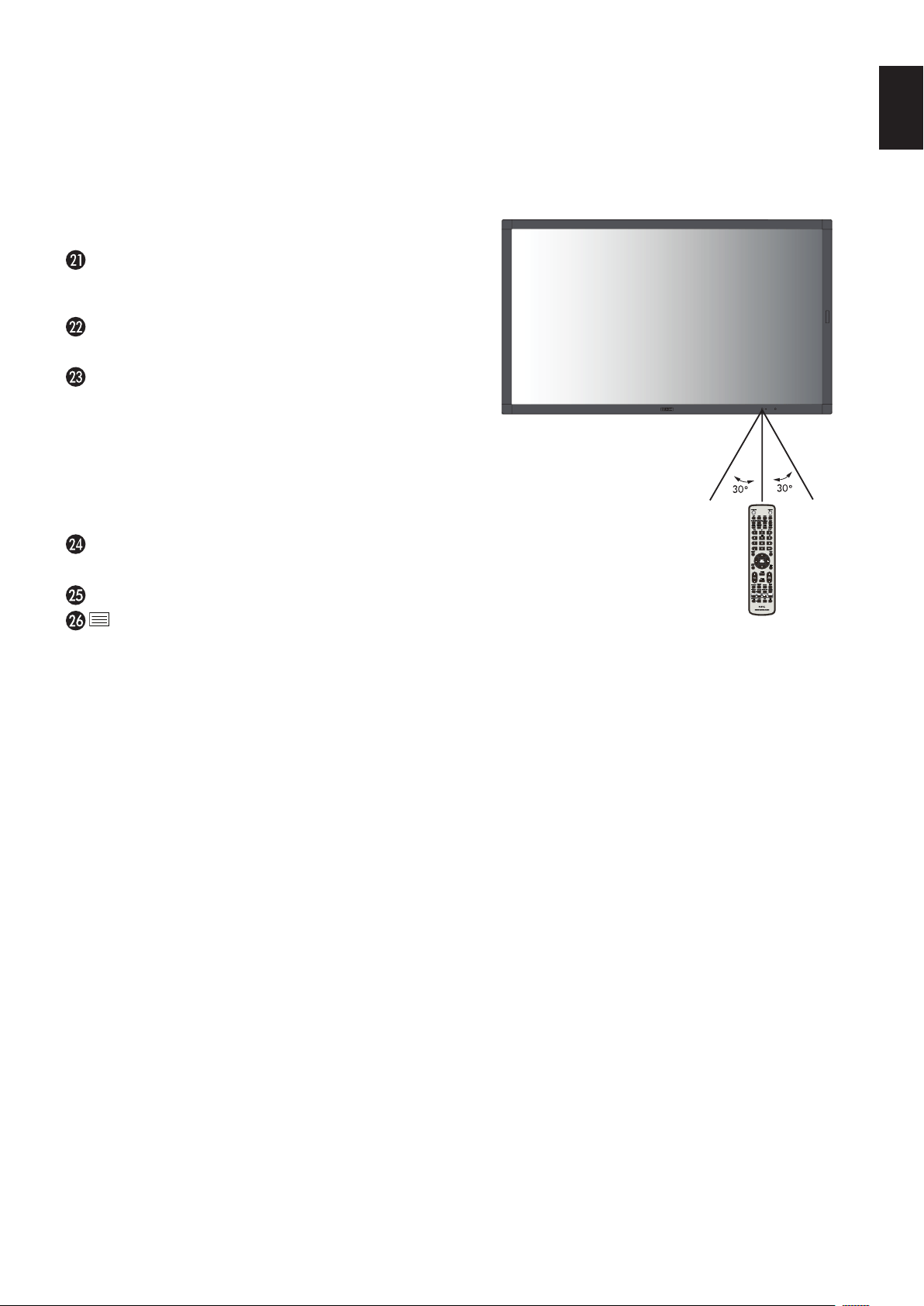
Operating Range for the Remote
Control
Point the top of the remote control toward the LCD monitor’s
remote control sensor during button operation.
Use the remote control within a distance of about 7 m (23 ft.)
from the remote control sensor, or at a horizontal and vertical
angleofwithin30°andwithinadistanceofabout3.5m(10ft.).
T STILL Button
ON/OFF Button: Activates/deactivates still picture mode.
CAPTURE Button: Captures still picture.
NOTE: This function deactivates when selecting MULTI
PICTURE MODE, TEXT TICKER, SCREEN SAVER, POINT
ZOOM, IMAGE FLIP except for NONE, SUPER in INPUT
CHANGE, TILE MATRIX.
CLOSED CAPTION is not available when STILL is active.
If input signal is OPTION, this button’s actions depend on
which option board you are using.
IMAGE FLIP Button
Toggleswitchesbetween[HFLIP],[VFLIP],[180°ROTATE]
and [NONE]. See page 34.
ACTIVE PICTURE Button
Selects active picture.
MULTI PICTURE Button
ON/OFF Button: Toggle switches between ON and OFF.
MODE Button: Selects a mode from PIP (picture in picture)
or PBP (picture by picture).
CHANGE Button: Swaps images between two pictures.
PICTURE ASPECT Button: Selects active picture frame
aspect.
NOTE: Enable to change each multi picture size by pressing
SET/POINT ZOOM button during multi picture mode.
REMOTE ID Button
Activates the REMOTE ID function. See page 46.See page 46.
MTS Button*
1
Button*
1
Activates closed captioning.
NOTE: VIDEO input only.
*1: This button’s action depends on which option board you are using.
Refer to the option board’s user’s manual for further information.
NOTE: The buttons with no explanation do not function.
Caution: Important, the remote control
system may not function
when direct sunlight or
strong illumination strikes
the remote control
sensor, or when there is
an object in the path.
Handling the remote control
•Donotexposetostrongshock.
•Donotallowwaterorotherliquidto
splash on the remote control. If the
remote control gets wet, wipe it dry immediately.
•Avoidexposuretoheatandsteam.
•Excepttoinstallthebatteries,donotopentheremote
control.
English-14
1. Determine the installation location
CAUTION
•InstallingyourLCDmonitormustbedonebyaqualied
technician. Contact your supplier for more information.
•MOVINGORINSTALLINGTHELCDMONITORMUST
BE DONE BY TWO OR MORE PEOPLE. Failure to follow
this caution may result in injury if the LCD monitor falls.
•Donotmountoroperatethemonitorupsidedown.
NOTE: This LCD monitor has internal temperature
sensors and cooling fans, including a fan for the
option board.
If the LCD monitor becomes too hot, the cooling
fans will turn on automatically.
The option board’s fan is active although the
temperature is lower than normal operating
temperature for cooling the option board. If the
LCD monitor becomes overheated while the
cooling fan is running, a “Caution” warning will
appear. If the “Caution” warning appears, stop
using the unit and allow it to cool. Using the
cooling fans will reduce the likelihood of early unit
failure and may help reduce image degradation
and “Image Persistance”.
CAUTION: If the LCD monitor is used in an enclosed
area or if the LCD panel is covered with
a protective screen, please check the
inside temperature of the monitor by using
the “HEAT STATUS” control in the OSD
(see page 40). If the temperature is higher ature is higher
than the normal operating temperature,
please turn the cooling fan to ON within
the FAN CONTROL menu within the OSD
(see page 40).
IMPORTANT: To avoid scratching the LCD panel, always
place a soft cloth, such as a blanket that is
larger than the monitor’s screen area, on the
table before laying the monitor face down.
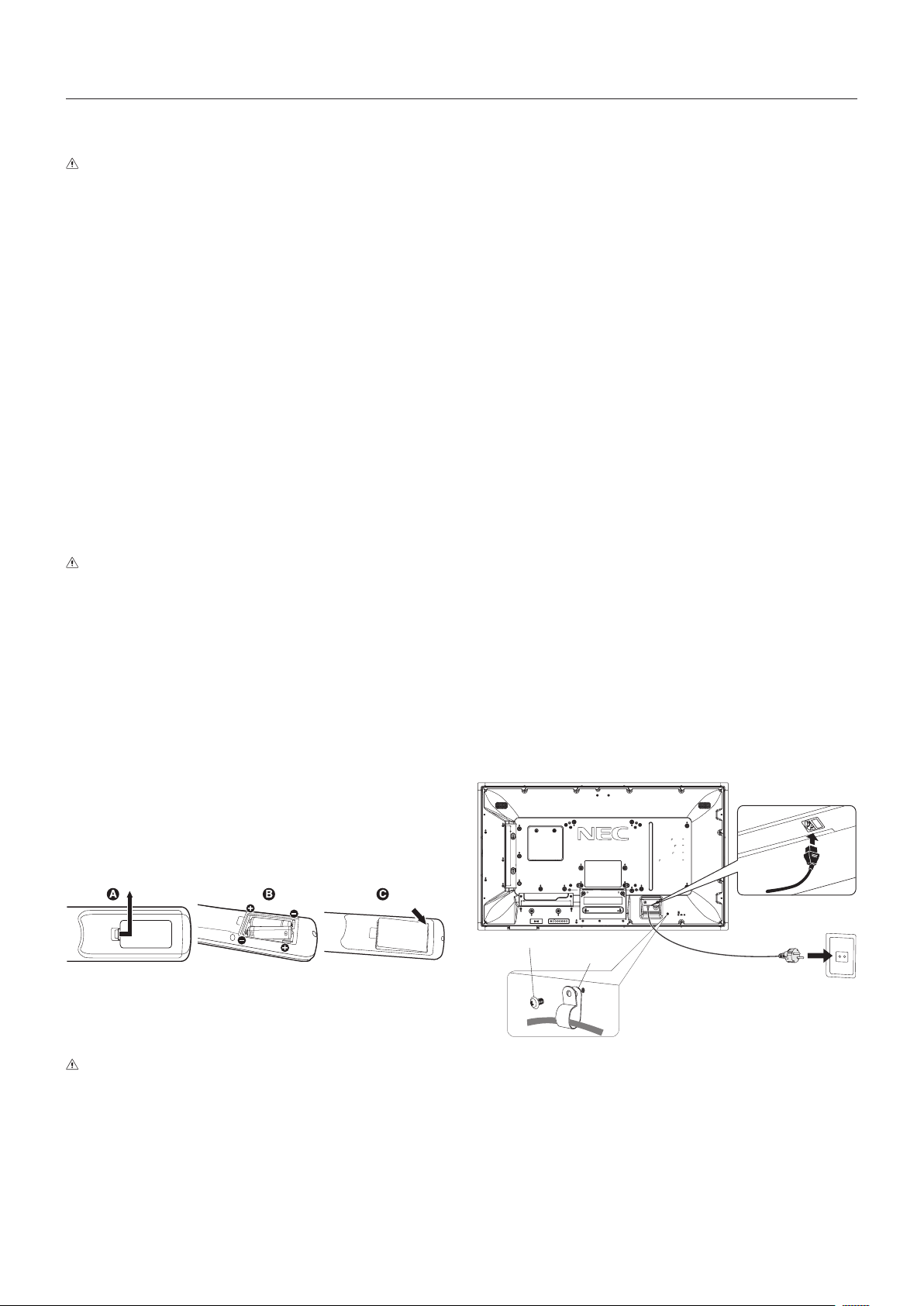
2. Install the remote control batteries
The remote control is powered by two 1.5V AAA batteries.
To install or replace batteries:
A. Press and slide to open the cover.
B. Align the batteries according to the (+) and (–) indications
inside the case.
C. Replace the cover.
CAUTION: Incorrect usage of batteries can result in
leaks or bursting.
NEC recommends the following battery use:
•Place“AAA”sizebatteriesmatchingthe(+)and(-)signs
on each battery to the (+) and (-) signs of the battery
compartment.
•Donotmixbatterybrands.
•Donotcombinenewandoldbatteries.Thiscanshorten
battery life or cause liquid leakage of batteries.
•Removedeadbatteriesimmediatelytopreventbattery
acid from leaking into the battery compartment.
•Donottouchexposedbatteryacid,itmayinjureyourskin.
NOTE: If you do not intend to use the Remote Control for
a long period of time, remove the batteries.
3. Connect external equipment
(See page 16, page 17 and page 18)
•Toprotecttheexternalequipment,turnoffthemainpower
before making connections.
•Refertothe user’s manual of your equipment for further
information.
NOTE: Do not connect/disconnect cables when turning
on the monitor or other external equipment, as this
may result in a loss of the monitor image.
4. Connect the supplied power cord
•Theequipmentshouldbeinstalledclosetoaneasily
accessible power outlet.
•FastenthepowercordtotheLCDmonitorbyattaching
the screw and clamp. (Recommended Fasten Force:
139 -189N•cm).
•Fullyinserttheprongsintothepoweroutletsocket.
A loose connection may cause image degradation.
NOTE: Please refer to the “Important Information” section
of this user’s manual for proper selection of an AC
power cord.
Screw
Clamp
Setup

English-15
English
5. Cable information
CAUTION: Use the provided specified cables with this
color monitor so as not to interfere with radio
and television reception.
For mini D-Sub 15-pin, DVI, and USB please
use a shielded signal cable with ferrite core.
For HDMI, DisplayPort, D-Sub 9-pin and
AUDIO, please use a shielded signal cable.
Use of other cables and adapters may
cause interference with radio and television
reception.
6. Switch on the power of all the attached
external equipment
When connected with a computer, switch on the power of the
monitor first.
7. Operate the attached external equipment
Show the signal on the screen from the desired input source.
8. Adjust the sound
Make volume adjustments when required.
9. Adjust the screen
(See page 33 and page 34)
Make adjustments to the image position, if necessary.
10. Adjust the image
(See page 32 and page 33)
Make adjustments such as backlight or contrast when
required.
11. Recommended Adjustments
To reduce the risk of the “Image Persistence”, please adjust
the following items based on the application being used:
“SCREEN SAVER”, “SIDE BORDER COLOR” (See page 40),
“DATE & TIME” (See page 36), “SCHEDULE SETTINGS”
(See page 35).
It is recommended that the “FAN CONTROL” setting
(See page 40) be checked ON also.
English-16
Connections
NOTE: Do not connect or disconnect cables when turning on the monitor’s main power or other external equipment’s power,
as this may result in a loss of the monitor image.
NOTE: Use an audio cable without a built-in resistor. Using an audio cable with a built-in resistor turns down the sound.
Before making connections:
* First turn off the power of all the attached equipment and make connections.
* Refer to the user’s manual included with each separate piece of equipment.
* We strongly recommend connecting or disconnecting a USB storage device or a microSD memory card to the monitor when
the monitor’s main power is off.
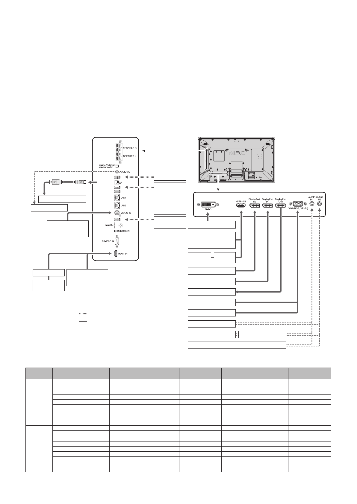
Wiring Diagram
USB1
USB2
USB CM1 (2A)
USB CM2
USB MP
VCR Player or
DVD Player (Video)
Stereo Amplifier
USB port
(Type-A)
USB devices
such as
USB camera or
USB memory
Devices that
require power
supply:
Ex:
MultiPresenter
Stick
USB storage
device
USB port
(Type-B)
USB cable
Computer (USB)*
1,
*
2
AV Amplifier
DVD Player
(HDMI)
DVD Player or
Computer
Computer (Digital)
DVD Player (HDMI) or
Computer (HDMI)
DVD Player
(HDMI)
AV
Amplifier
Computer (DisplayPort)
Computer (DisplayPort)
Second monitor*
Computer (Analog)
Computer
DVD Player (component)
DVD Player Stereo Amplifier
VCR player or DVD player
Dotted lines = other signal
Solid lines = video signal
Dashed lines = audio signal
*: Multiple monitors that are daisy-chained have a limit to the connectable monitors.
*
1
: The device connected to USB2 can control the device connected to USB1.
*
2
: The device connected to USB2 allows the touch panel function to work.
Connected
equipment
Connecting terminal
Setting in
TERMINAL SETTINGS
Input signal name Connecting audio terminal
Input button in
remote control
AV
DVI (DVI-D) DVI MODE: DVI-HD DVI IN1/IN2 DVI
HDMI IN1 VIDEO LEVEL: RAW/EXPAND*
3
HDMI1 HDMI1 HDMI1
HDMI IN2 VIDEO LEVEL: RAW/EXPAND*
3
HDMI2 HDMI2 HDMI2
DisplayPort IN1 VIDEO LEVEL: RAW/EXPAND*
3
DisplayPort 1 DisplayPort 1 DisplayPort 1
DisplayPort IN2 VIDEO LEVEL: RAW/EXPAND*
3
DisplayPort 2 DisplayPort 2 DisplayPort 2
VGA (RGB, YPbPr) VGA MODE: RGB VGA (RGB) IN1/IN2 VGA (RGB/YPbPr)
VGA (RGB, YPbPr) VGA MODE: YPbPr VGA (YPbPr) IN1/IN2 VGA (RGB/YPbPr)
VIDEO IN — VIDEO IN1/IN2 VIDEO
Option board slot (SLOT2) VIDEO LEVEL: RAW/EXPAND*
3
OPTION OPTION (ANALOG/DIGITAL)*
3
OPTION
PC
DVI (DVI-D) DVI MODE: DVI-PC/DVI-HD DVI IN1/IN2 DVI
HDMI IN1 VIDEO LEVEL: RAW/EXPAND*
3
HDMI1 HDMI1 HDMI1
HDMI IN2 VIDEO LEVEL: RAW/EXPAND*
3
HDMI2 HDMI2 HDMI2
DisplayPort IN1 VIDEO LEVEL: RAW/EXPAND*
3
DisplayPort 1 DisplayPort 1 DisplayPort 1
DisplayPort IN2 VIDEO LEVEL: RAW/EXPAND*
3
DisplayPort 2 DisplayPort 2 DisplayPort 2
VGA (RGB, YPbPr) VGA MODE: RGB VGA (RGB) IN1/IN2 VGA (RGB/YPbPr)
VGA (RGB, YPbPr) VGA MODE: YPbPr VGA (YPbPr) IN1/IN2 VGA (RGB/YPbPr)
VIDEO IN — VIDEO IN1/IN2 VIDEO
Option board slot (SLOT2) VIDEO LEVEL: RAW/EXPAND*
3
OPTION OPTION (ANALOG/DIGITAL)*
3
OPTION
*
3
: Please set appropriate setting for input signal.
English-17
English
Connecting a Personal Computer
Connecting your computer to your LCD monitor will enable you to reproduce your computer’s video signal output.
Some display cards may not be able to support the required resolution for proper image reproduction.
Your LCD monitor shows proper image by adjusting the factory preset timing signal automatically.
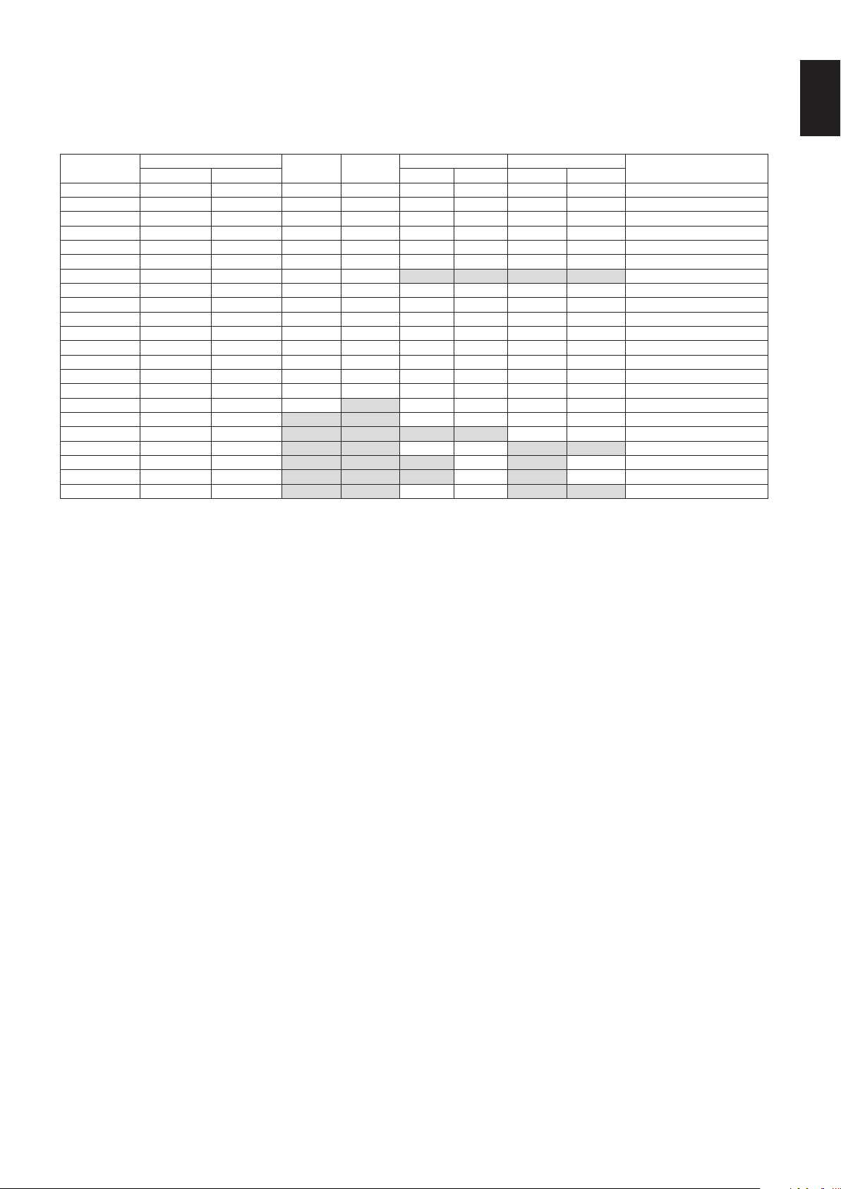
<Typical factory preset signal timing>
Resolution
Scanning frequency
VGA DVI
HDMI DisplayPort
Remarks
Horizontal Vertical MODE1 MODE2 1.1a 1.2
640 x 480 31.5 kHz 60 Hz Yes Yes Yes Yes Yes Yes
800 x 600 37.9 kHz 60 Hz Yes Yes Yes Yes Yes Yes
1024 x 768 48.4 kHz 60 Hz Yes Yes Yes Yes Yes Yes
1280 x 720 45.0 kHz 60 Hz Yes Yes Yes Yes Yes Yes
1280 x 768 47.8 kHz 60 Hz Yes Yes Yes Yes Yes Yes
1280 x 800 49.7 kHz 60 Hz Yes Yes Yes Yes Yes Yes
1280 x 960 60.0 kHz 60 Hz Yes Yes No No No No
1280 x 1024 64 kHz 60 Hz Yes Yes Yes Yes Yes Yes
1360 x 768 47.7 kHz 60 Hz Yes Yes Yes Yes Yes Yes
1366 x 768 47.7 kHz 60 Hz Yes Yes Yes Yes Yes Yes
1400 x 1050 65.3 kHz 60 Hz Yes Yes Yes Yes Yes Yes
1440 x 900 55.9 kHz 60 Hz Yes Yes Yes Yes Yes Yes
1600 x 1200 75.0 kHz 60 Hz Yes Yes Yes Yes Yes Yes Compressed image
1680 x 1050 65.3 kHz 60 Hz Yes Yes Yes Yes Yes Yes
1920 x 1080 67.5 kHz 60 Hz Yes Yes Yes Yes Yes Yes Recommended resolution
1920 x 1200 74.6 kHz 60 Hz Yes No Yes Yes Yes Yes Compressed image
1920 x 2160 133.3 kHz 60 Hz No No Yes Yes Yes Yes Compressed image
3840 x 2160 65.7 kHz 30 Hz No No No No Yes Yes Compressed image
3840 x 2160 67.5 kHz 30 Hz No No Yes Yes No No Compressed image
3840 x 2160 133.3 kHz 60 Hz No No No Yes No Yes* Compressed image
3840 x 2160 135.0 kHz 60 Hz No No No Yes No Yes* Compressed image
4096 x 2160 54.0 kHz 24 Hz No No Yes Yes No No Compressed image
*: Only HBR2 is set.
•InputTMDSsignalsconformingtoDVIstandards.
•Tomaintainthe image reproduction quality, use a cable that conforms to DVI standards.
Connecting a Player or Computer with HDMI
•PleaseuseaHDMIcablewiththeHDMIlogo.
•Itmaytakeamomentforthesignaltoappear.
•Somedisplaycardsordriversmaynotdisplayanimagecorrectly.
•WhenyouuseacomputerwithHDMI,pleasesetOVERSCANto“AUTO”or“OFF”(seepage34).
•Please check display card when image is compressed with 1920 x 1080.
•To output HDMI audio, set [HDMI1] or [HDMI2] at AUDIO INPUT in the OSD or choose [HDMI1] or [HDMI2] by the remote
control AUDIO INPUT button.
•If the input resolution is 3840 x 2160 (60 Hz), please set MODE2 at HDMI in TERMINAL SETTINGS (See page 37).
•If the monitor’s main power is turned on after a connected computer is turned on, sometimes images are not displayed.
In this case, please turn off the computer then turn it on again.
Connecting a Computer with DisplayPort
•PleaseuseaDisplayPortcablewiththeDisplayPortcompliancelogo.
•To use the DisplayPort out connector, please refer to Video out (See page 61).
•Itmaytakeamomentforthesignaltoappear.
•WhenconnectingaDisplayPortcabletoacomponentwithasignalconversionadapter,animagemaynotappear.
•SelectDisplayPortcablesfeaturealockingfunction.Whenremovingthiscable,holddownthetopbuttontoreleasethelock.
•To output DisplayPort audio, set [DisplayPort1] or [DisplayPort2] at AUDIO INPUT in the OSD or choose [DisplayPort1] or
[DisplayPort2] by the remote control AUDIO INPUT button.
•To display individual images at each connected monitors with the DisplayPort out connector, please set DisplayPort1.2 and
MST at DisplayPort in the TERMINAL SETTINGS (See page 37).
•If the monitor’s main power is turned on after a connected computer is turned on, sometimes images are not displayed.
In this case, please turn off the computer then turn it on again.
English-18
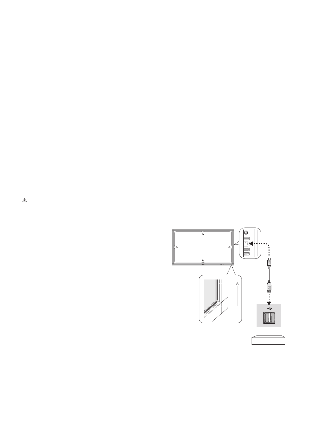
B Type
A Type
Computer
Figure 1
A: Sensor
Connecting a USB device
USB1: USB downstream port (Type-A).
Connect a USB compatible flash memory or keyboard to Down Stream Port.
USB2: USB upstream port (Type-B).
Connect to a USB compatible computer with a USB cable.
A USB compatible computer connected to USB2 can control the devices connected to USB1.
The device connected to USB2 allows the touch panel function to work.
USB CM1 (2A): Power supply port.
Please refer to the specifications page for power supply information (see page 65, page 66 and page 67).
USB CM2: Service port.
Please do not connect devices.
USB MP: USB downstream port (Type-A).
To use the Media Player function, please use this port.
•Pleasemakesuretheconnectorshapeandorientationis correctly aligned when connecting the USB device or cable.
•DependingontheuseofcomputerBIOS,OSordevice,theUSBfunctionmaynotbeworking.Inthiscase,pleasecheck
user’s manual of your computer or device, or contact your supplier for detailed information.
•BeforeturningoffthemainpowerswitchofthemonitororshuttingdownWindows
®
, please turn off the USB function and
remove the USB cable from the monitor. You may lose data when the computer crashes.
•ItmaytakeafewsecondsuntilthemonitorrecognizestheUSBinput.DonotdisconnecttheUSBcableordisconnect and
reconnect the USB cable before the monitor recognizes the input.
•You can set power supply for USB CM1 (2A) at USB POWER in the OSD menu (see page 43).
•When you use the USB CM1 (2A) port for power supply, please use a USB cable that supports 2A.
•Please refer to the USB in the OSD menu (See page 43) for the USB setting.
NOTE: USB CM1 (2A) and USB CM2 are not corresponding port.
Please refer to the connection (See page 16) to connect USB devices to the monitor.
CAUTION: Do not bind the USB cable. It may trap heat and start a fire.
For using Touch Panel
1. Turn off the monitor.
2. Install the equipment.*
1
- Using slot 2 type PC:
Connect the slot 2 type PC into the option board slot.
NOTE: Please refer to the slot 2 type PC’s manual for
connection.
NOTE: When you set option board accessory other than
slot 2 type PC, touch function may not work.
- Using external computer:
Connect the B type connector to the USB upstream port on the
left back side of the monitor and the A type connector to the
downstream port on the external computer (Figure 1).
3. Turn on the monitor.
*1: Please contact your NEC customer support for more detailed information.
Please contact your NEC customer support for the setting of the touch panel
function in multiple screens.
Monitor Setting
Select the input signal.
- Using slot 2 type PC: Select [OPTION]
- Using external computer: Select the input signal which is
supplied by the computer connected to USB connector.
NOTE: Please refer to “The touch panel does not respond” in
“Troubleshooting” when the touch panel function does not work.
English-19
English
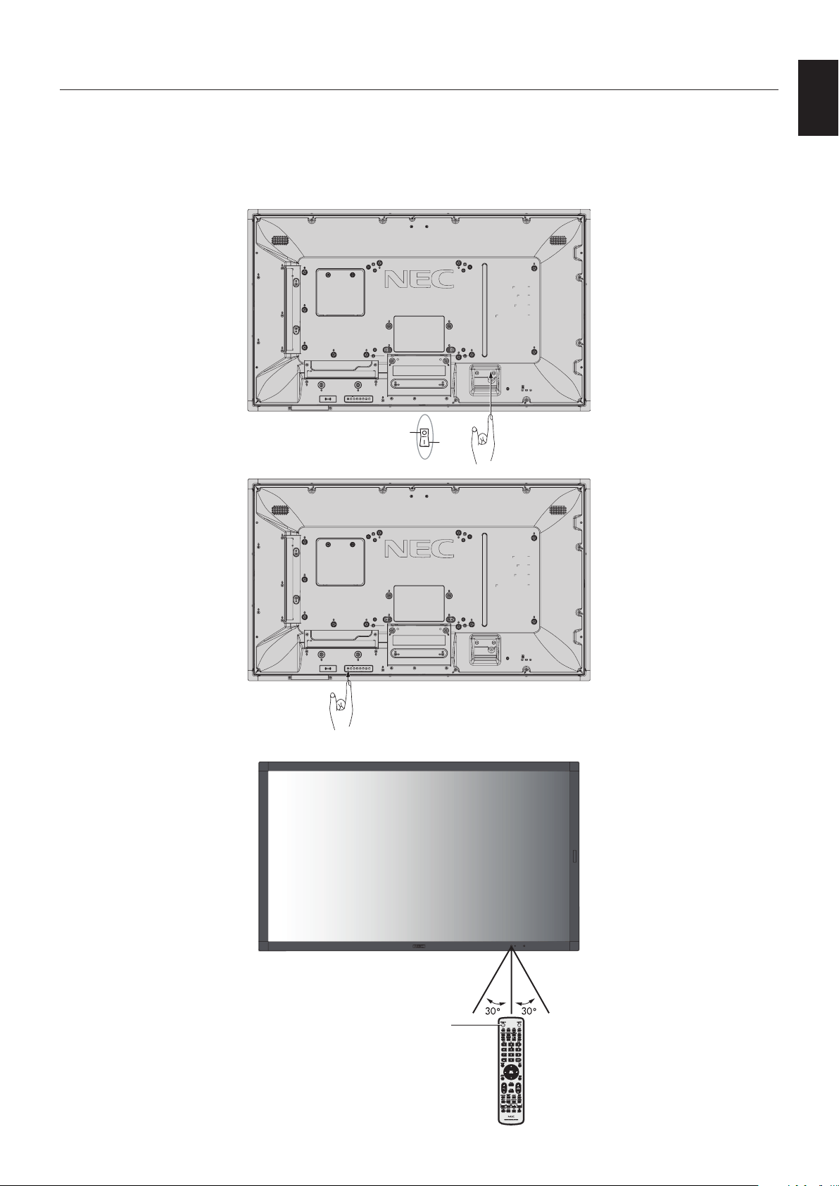
Basic Operation
Power ON and OFF Modes
The LCD monitor power indicator will turn blue while powered on.
NOTE: The Main Power switch must be in the ON position in order to power up the monitor using the remote control or the
Power button.
Main Power Switch
OFF
ON
Power Button
Using the remote control
POWER ON button
English-20
Aspect
For MP, VIDEO
FULL
ZOOM NORMAL
For DVI, DisplayPort1, DisplayPort2, VGA (RGB), OPTION*
1
FULL
1:1 ZOOM NORMAL
For VGA (YPbPr), HDMI1, HDMI2
FULL WIDE DYNAMIC 1:1 ZOOM NORMAL
*1: This function depends on which option board you are using.
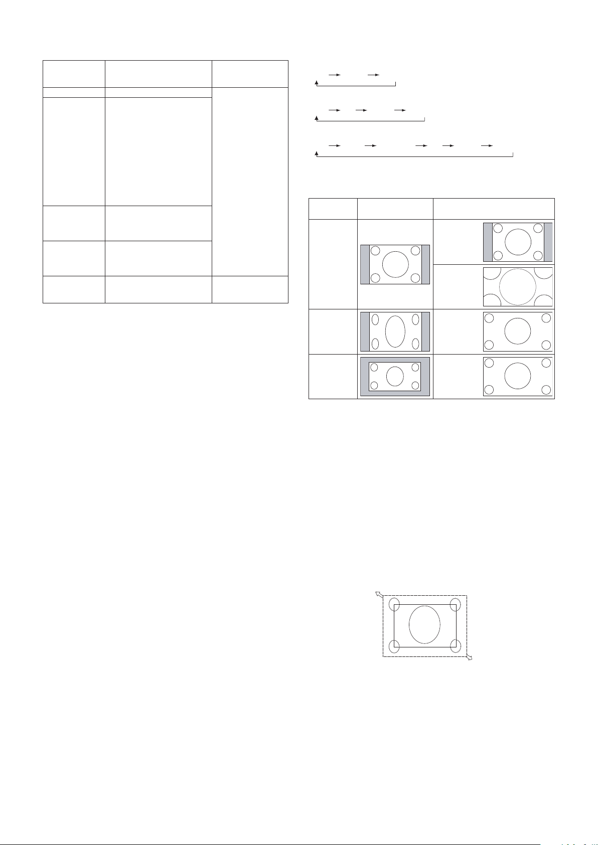
Aspect ratio
of image
Unchanged view*
3
Recommended selection
for picture aspect*
3
4:3
NORMAL
DYNAMIC
Squeeze
FULL
Letterbox
WIDE
*
3
Grey areas indicate unused portions of the screen.
NORMAL: Reproduces the aspect ratio that is sent from the
source.
FULL: Fills the entire screen.
WIDE: Expands a 16:9 letter box signal to fill the entire
screen.
DYNAMIC: Expands a 4:3 pictures to fill the entire screen
with non-linearity. Some of the outside image area will be cut
off due to expansion.
1:1: Shows the image in a 1 by 1 pixel format.
ZOOM
The image can be expanded beyond the active screen area.
The image which is outside of the active screen area is not
shown.
ZOOM
ZOOM
Power Indicator
LED indicator
status and
lighting pattern
Condition Recovery
Glowing blue Normal
1. Turn on the monitor
by the remote
control or the
monitor button.
2. Send an AV signal
input to the monitor.
Blinking green*
1
Meeting one of the conditions
below when the monitor has
been past a certain amount of
time with no signal input which
you set.
•Themonitorisusinganoption
board.
•INPUT DETECT is set to a
setting except for NONE.
•USB POWER is set to ON.
•DisplayPort in the TERMINAL
SETTINGS is set to MST.
Glowing amber The monitor has been past a
certain amount of time with
[network signal input] and [no
AV signal input which you set].
Blinking amber No AV signal input has been
detected by the monitor during
the period of time you set.
(no network signal input)
Glowing red Turn off the monitor by the
remote control or the monitor
button.
Turn on the monitor by
the remote control or
the monitor button.
*1: Time setting for AUTO POWER SAVE is available at POWER SAVE
(See page 40).
NOTE: If the indicator is blinking red in a combination
of long and short, a certain failure might have
occurred, please contact your supplier.
Using Power Management
This LCD monitor follows the VESA approved DPM (Display
Power Management) function.
The power management function is an energy saving
function that automatically reduces the power consumption
of the monitor when the keyboard or the mouse has not been
used for a fixed period.
This allows your LCD monitor to enter a Power Management
mode if the monitor’s POWER SAVE function is set to
ENABLE, and a certain amount of time has passed since the
monitor recognized “no signal input”. It will increase the life
and decrease the power consumption of the monitor.
NOTE: Depending on the computer and display card
used, this function may not operate.
After the video signal was lost, the monitor
automatically goes into OFF at a preset time
period.
English-21
English
Media Player
Plays saved data, such as still and motion images, BGM (Background Music), on a USB storage device or microSD memory
card connected to the monitor.
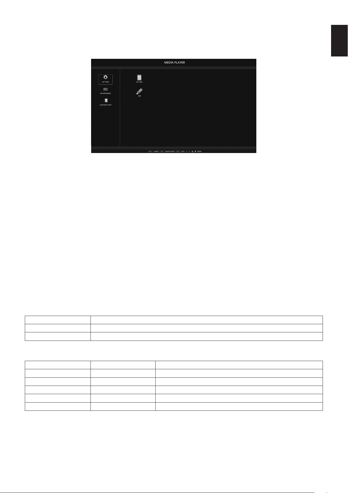
Top screen of the viewer
• Select [SETTINGS] to change the media player settings.
• While “AUTO PLAY” has been set to SLIDESHOW in SETTINGS, the monitor starts performing “AUTO PLAY” by the
operation below:
- When connecting a USB storage device to the USB MP (Terminal Panel page 10), with the monitor already powered ON
and the Media Player top screen displayed.
- When the input signal is changed to MP, with a USB storage device already connected to the USB (2A) port of the monitor.
For starting “AUTO PLAY”, the system will automatically search the folder which is set in the AUTO PLAY settings FOLDER
field, in the USB storage device and then display found still images or movies. The images and movies will be displayed in the
“Sorted” order.
NOTE: Only 1 USB storage device can be recognized by the viewer.
A window will appear when you press the control panel buttons while the Media Player is active. You can select to control either
the OSD menu or the Media Player from the window that opens.
If Media Player contents are played while TILE MATRIX is active, the image play timing might have a gap within monitors.
If a monitor is used in portrait position, please set OSD ROTATION to PORTRAIT. Image orientation is changed according to
what you set at OSD ROTATION.
When OSD ROTATION is set to PORTRAIT, please use the motion image, which is rotated anticlockwise by 90°.
Displayable/playable files
Still
Supported formats
File extension Supported
.jpg, .jpeg, .jpe Baseline, Progressive, RGB, CMYK
.png
Interlace, α channel
Motion image
Supported formats
File extension Video codec Audio codec
.mpg, .mpeg MPEG1, MPEG2 MPEG Audio Layer3 (Abbreviation: MP3) AAC-LC (Abbreviation: AAC), LPCM
.wmv H.264, WMV MP3, WMV Standard, WMA 9/10 Professional
.mp4 H.264 MP3, AAC
.mov H.264 MP3, AAC
.flv, .f4v H.264 MP3, AAC
English-22
BGM
Supported formats
File extension Audio codec
.wav LPCM
.mp3 MP3
Information
Item Conditions
Resolution JPEG 5000x5000
PNG 4000x4000
MPEG1 480@30fps
MPEG2 MP@ML, MP@HL, 1080p@30fps / 1080i@60fps
H.264 High profile Lv.4.2, 1080p@30fps / 1080i@60fps
WMV Advanced@L3, Simple&Main
Video bit date - Up to 15Mbps
Audio sampling rate - Up to 48KHz
Audio bit rate MP2 Up to 384Kbps
MP3 Up to 320Kbps
AAC Up to 1440Kbps
NOTE: Depending on the file, it may not play even when it satisfies all above mentioned conditions.
Depending on network environments, the type of USB storage device, and file bitrate, it may not play still image files.
You cannot play DRM (Digital Right Management) files.
The maximum resolution for a motion image is 1920 (Horizontal) x 1080 (Vertical).
Compatible microSD memory card
Format a microSD memory card in the FAT32 format or FAT16 format.
Refer to the computer’s instruction user’s manual or Help file on how to format a microSD memory card.
Information
Up to 32GB microSDHC is supported.
NOTE: It is not guaranteed to work with all microSD memory card sold commercially.
microSD with CPRM is not supported.
microSD UHS-1 or UHS-2 are not supported.
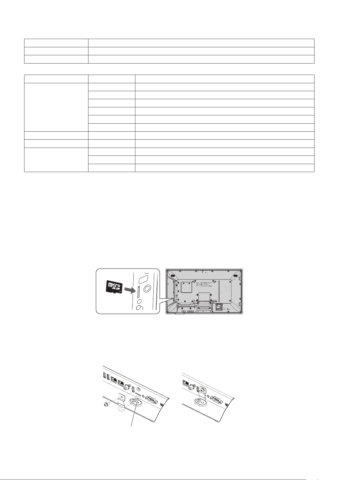
• When inserting a microSD memory card, please make sure of the microSD memory card direction then insert it correctly.
• When ejecting a microSD memory card from the microSD card slot, press the center of the microSD memory card then take
it out.
Installing microSD card slot cover
To secure your microSD memory card, we recommend you install the microSD card slot cover.
Please insert the edge of the microSD card cover to the hole. (Recommended Fasten Force: 139 - 189N•cm).
microSD card cover is set.Hole
English-23
English
Compatible USB memory
Format a USB memory in the FAT32 format or FAT16 format for using it in the Media Player. Refer to the computer’s instruction
user’s manual or Help file on how to format a USB memory.
Please use a USB memory with this monitor in accordance with the drawing below.
If the physical size of the USB device is larger than the supported sizes listed below, please use a USB extension cable.
Under 34 mm
Under 29 mm
USB memory
Extension cable
NOTE: Check the format if this device cannot recognize the connected USB memory.
It is not guaranteed to work with all USB memories sold commercially.
Please connect the USB memory to USB MP (See page 18).
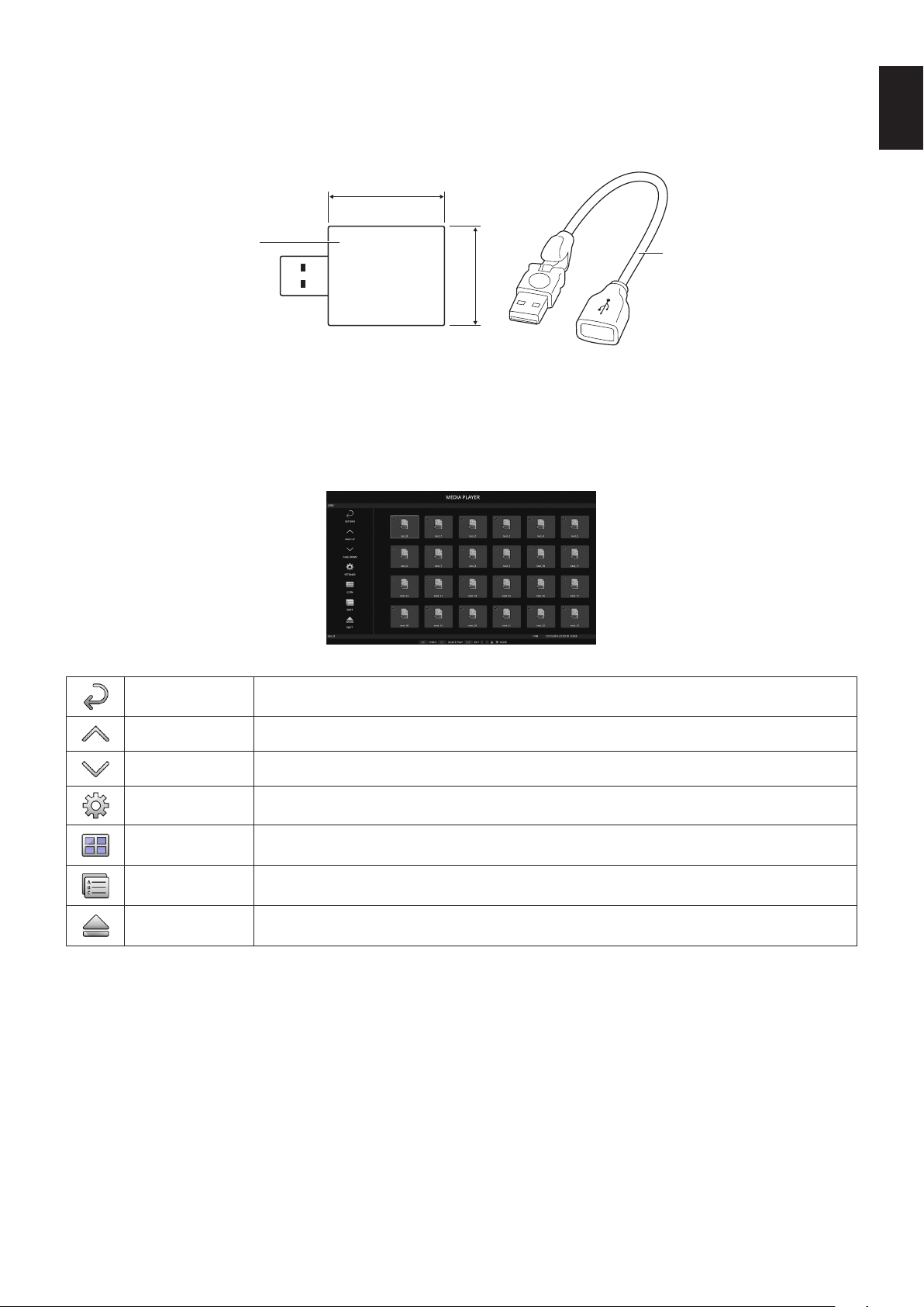
File display screen
The files can be displayed using either icons or thumbnails in the Media Player.
Icon display
RETURN Goes back one subsequent level higher.
PAGE UP Displays a list of the previous files.
PAGE DOWN Displays a list of the next files.
SETTINGS Displays the setting screen.
THUMBNAILS/ICON Switches between thumbnail display and icon display.
SORT Changes the order to display files by name (filename), type (file extension), date (date of creation), or size
(file capacity). The default sorting order is by “Name”.
EJECT Disconnects from the USB storage device or the microSD memory card inserted to the monitor. Please
select EJECT when file list is displayed.
NOTE: The maximum number of files that can be displayed in a folder including folder icons is 300.
A folder hierarchy is shown up to level 16.
The icon of a file whose type cannot be determined is indicated by a “?”.
Depending on the file, thumbnail cannot be displayed.
English-24
Slideshow display
• Select a folder that contains images or movies.
• A slideshow can be displayed using “MANUAL” in which the images are switched by operating a button on the remote
control, or “AUTO” in which the images are switched automatically at a set interval (PLAY MODE is “AUTO”).
• The default factory setting is “MANUAL”. To perform “AUTO”, set the “PLAY MODE” to “AUTO”.
• The images will be displayed in the order selected under “Sort” on the file display screen.
• When still images in high resolutions are displayed as the Slideshow, it may go back to the file display screen.
Media Player settings
Select the
icon in the file list screen or top screen of the Media Player to display the configuration screen of the Media Player.
The following settings can be configured on the configuration screen.
SLIDESHOW
Menu Function
SCREEN SIZE Selects ACTUAL SIZE or BEST FIT.
PLAY MODE Selects AUTO or MANUAL.
INTERVAL Sets interval time.
REPEAT Check the check box to repeat slideshow.
AUDIO FILE Selects an audio file.
BGM Check the check box to enable BGM.
PLAY END SCREEN Selects a setting for when the slideshow finishes.
BLACK SCREEN: When the slideshow finishes, a black screen is displayed.
FILE LIST: When the slideshow finishes, it goes back to the file list screen.
SAVE LAST SCREEN: When the slideshow finishes, the last slideshow image is kept on the screen.
AUTO PLAY
Automatically displays selected folder when the input signal is changed to MP, while “AUTO PLAY” has been set to
SLIDESHOW.
Menu Function
AUTO PLAY OFF: Automatic play mode is off.
SLIDESHOW: Automatically plays a selected file.
FOLDER Select a file by SET/POINT ZOOM button and confirm by ENT button.
PRESET CONTENTS
Plays selected folder when the monitor has no signal input.
Menu Function
ENABLE Check the check box to enable preset contents.
FOLDER Select a file by SET/POINT ZOOM button and confirm by ENT button.
Please press OK to activate above settings.
If OK is not pressed, settings that you set are not activated.
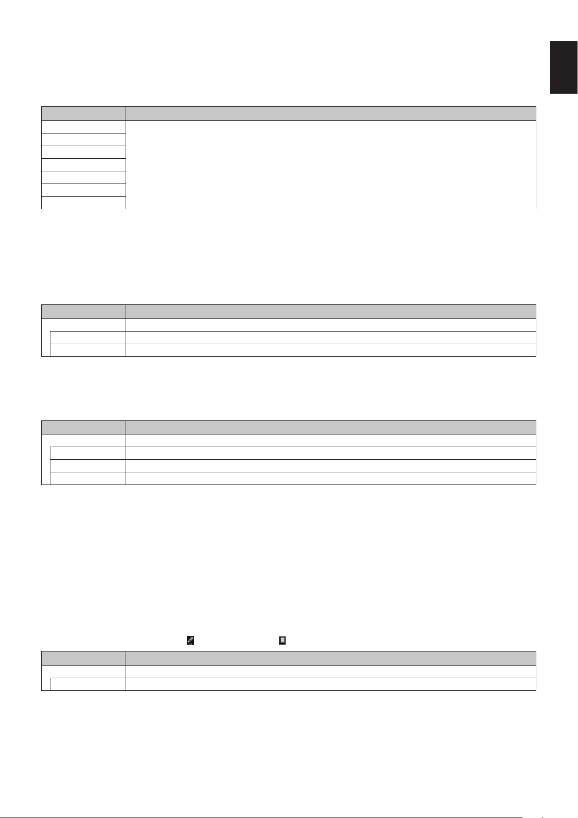
English-25
English
NETWORK & OTHER SETTINGS
Below are the options for the Network settings and Shared Folder settings for the Media Player.
To select the settings, press the remote control SET/POINT ZOOM button on the NETWORK & OTHER SETTINGS.
NETWORK SETTINGS for MEDIA PLAYER
Menu Function
IP SETTING Set these settings.
IP ADDRESS
SUBNET MASK
DEFAULT GATEWAY
DNS
DNS PRIMARY
DNS SECONDARY
NETWORK INFORMATION for the Media Player displays what you set in the NETWORK SETTINGS for the Media Player.
SHARED FOLDER
There are two settings for configuring the SHARED FOLDER.
Press the remote control SET/ZOOM button to open the shared settings options.
• SHARED SD CARD SETTINGS
Folders saved in a computer on the network can be copied to the connected microSD memory card using a web browser on
the connected computer.
Menu Function
ENABLE Check the checkbox to enable SHARED SD CARD SETTINGS.
USER NAME USER NAME is displayed. It is the same name as the monitor name and it is not changeable.
PASSWORD Set password.
Please press OK to activate settings in the SHARED SD CARD SETTINGS.
If OK is not pressed, settings that you set are not activated.
• SHARED FOLDER SETTINGS.
Folders saved in a computer on the network can be copied to the connected microSD memory card by controlling the
monitor.
Menu Function
ENABLE Check the checkbox to enable SHARED FOLDER SETTINGS.
SHARED FOLDER Set the IP address of the network shared folder location that contains the files for copying to the microSD card.
USER NAME Set USER NAME which is used when connecting the monitor to the shared folder.
PASSWORD Set password.
Please press OK to activate settings in the SHARED FOLDER SETTINGS.
If OK is not pressed, settings that you set are not activated.
1 to 4 shared folders can be set.
When the connection to the shared folder fails, an error message is displayed and an “x” is displayed in the folder icon.
Carry out the following checks in this case.
- Is the name of the destination folder correct?
- Is the destination folder set for sharing?
- Have access rights been set in the destination folder?
- Are there any displayable files saved in the destination folder?
SHIFT NO SIGNAL
This setting is for a situation when the monitor detects no signal input. If ENEBLE is ticked, the monitor goes to no signal status.
The monitor detects no signal when the monitor is in the following conditions:
- After contents or images are played.
- While the monitor is displaying USB
window or SD CARD window.
Menu Function
ENABLE Check the checkbox to enable SHIFT NO SIGNAL.
INTERVAL Set the time when the monitor goes into no signal after displayed detected items.
Please press OK to activate settings in the SHIFT NO SIGNAL.
If OK is not pressed, settings that you set are not activated.
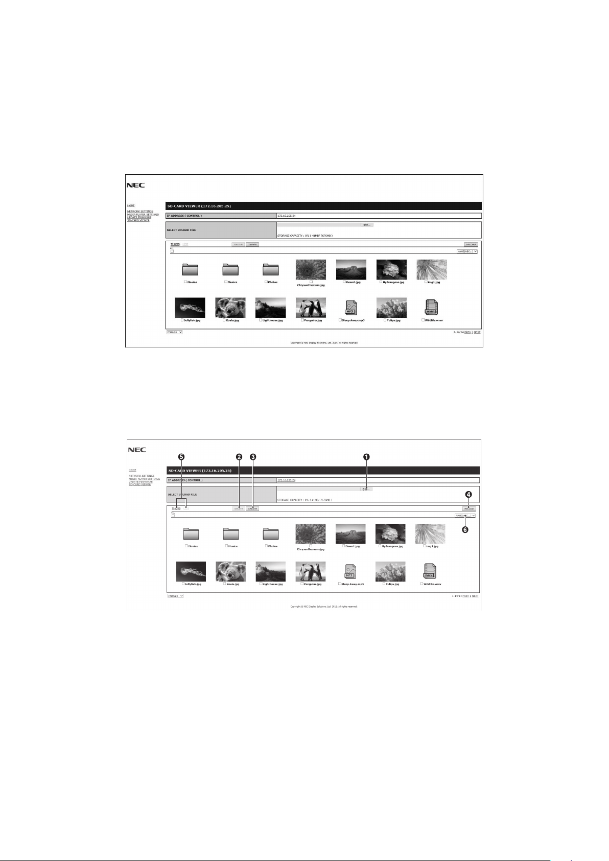
English-26
Using SHARED SD card SETTINGS
You can copy data to the microSD memory card, such as motion or still images, from a computer connected to the same
network as the monitor.
Please set the NETWORK SETTINGS for the Media Player (See page 25) first to copy data.
NOTE: When the monitor is copying a folder, the LED indicator blinks in red.
When the monitor is in this condition, do not eject a microSD memory card from the monitor and do not turn off the
monitor’s main power. Ejecting the microSD card or turning off the monitor while copying files may corrupt the data.
If you press the STANDBY button on the remote control or the POWER button on the monitor while the LED indicator
is blinking in red, the monitor goes into standby after completing the folder copy.
Files which you can copy are still, motion image and BGM only.
Setting procedure
1. Open the Monitor LAN control of the network connected monitor then select SD-CARD VIEWER.
2. Select SEARCH to display the IP ADDRESS of the currently connected monitor and all compatible monitors on the same
network.
3. Select the IP ADDRESS of the currently connected monitor.
4. Enable upload, delete and sort files that are saved in the microSD memory card connected to the monitor.
Function
1. SELECT UPLOAD.
Press SELECT then choose the files to be copied to the microSD memory card.
File upload window appears and shows the selected files.
Once OK is selected, file uploading starts.
NOTE: Please check the microSD memory card storage capacity before copying files.
STORAGE CAPACITY shows the connected microSD memory card capacity.
2. DELETE.
Select files or folders.
DELETE FOLDERS/FILES window appears.
Once OK is selected, the selected files or folders are deleted.
3. CREATE.
A new folder is created in the microSD memory card connected to the monitor.
Insert folder name and select OK. A maximum of 255 alphanumeric characters is allowed.
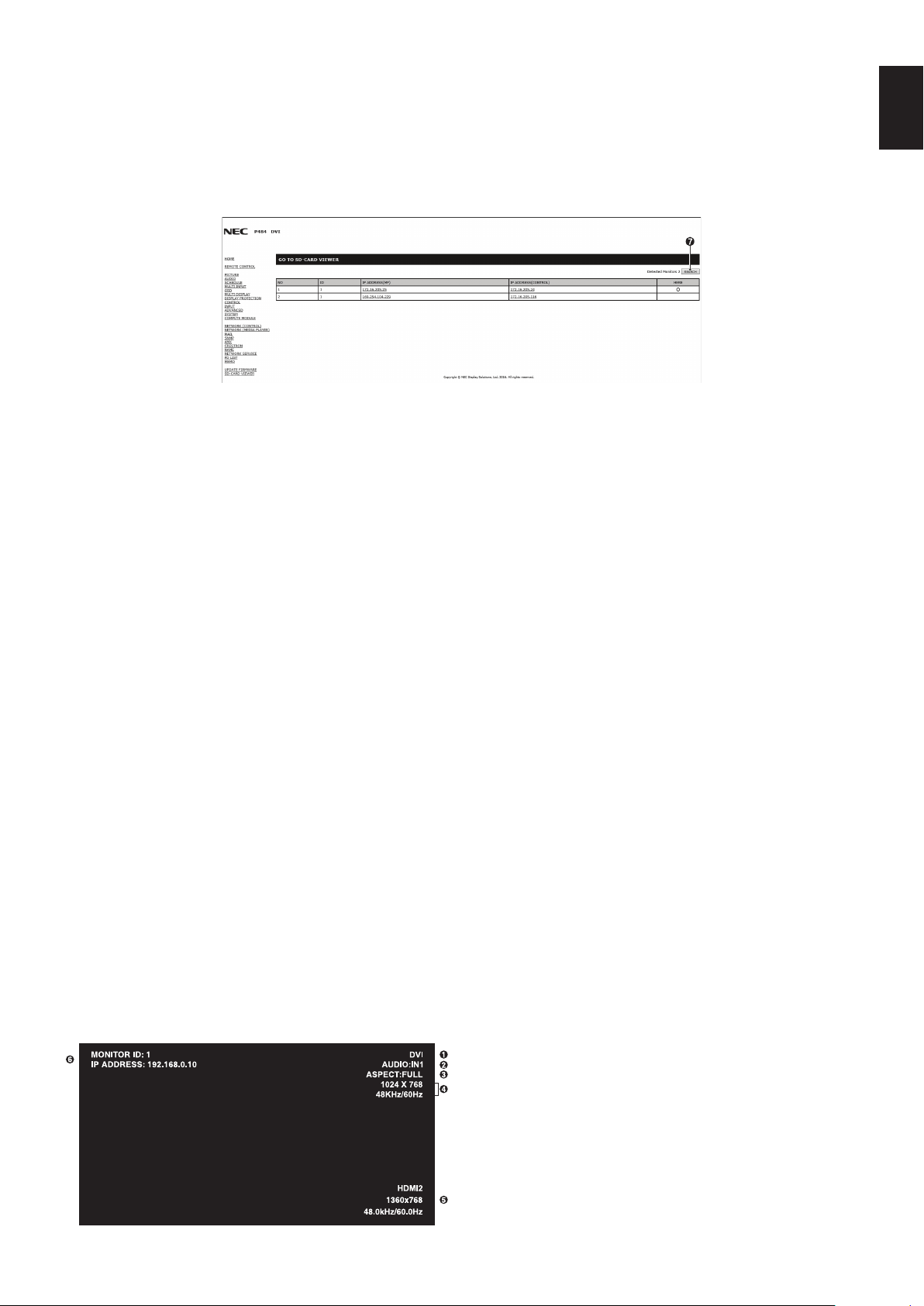
English-27
English
4. RELOAD.
Updates microSD memory card data.
5. THUMB/LIST.
The files can be displayed using either icons or thumbnails.
Displays description of the file or folder if you select thumb name or file name.
6. SORT.
Select sort type. The folders saved in the microSD are sorted based on what you selected in sort type.
7. Connect to the other monitor’s SD-CARD VIEWER then open them.
By running the SEARCH, as described on the previous page, this window shows all compatible monitors on the same
network as the current monitor.
To open the other monitor’s web page in a new tab, right-click on its IP address. To open the other monitor’s web page in
a new window, left-click on its IP address
Using CONTENTS COPY
You can copy all data saved in a USB storage device or saved in a shared folder, which is set in the connected computer or a
server, to a microSD memory card.
For copying shared folder data, please set SHARED FOLDER SETTINGS (See page 25) first.
1. Select CONTENTS COPY at the top screen of the Media Player.
2. Select a USB storage device or a folder.
3. Select OK to start copying. All data saved in the folder or device is copied to the microSD memory card and the original data
saved in the microSD memory card is deleted.
NOTE: “Out of disk space” is displayed if the microSD memory card storage capacity is not enough to copy selected folders.
When contents copy has occurred, previous data that was saved in the microSD memory card is deleted.
Only devices connected to the monitor are shown.
When the monitor is copying a folder, the LED indicator blinks in red.
When the monitor is in this condition, do not eject the microSD memory card from the monitor and do not turn off the
monitor’s main power. Ejecting the microSD card or turning off the monitor while copying files may corrupt the data.
If you press the STANDBY button on the remote control or the POWER button on the monitor while the LED indicator
is blinking in red, the monitor goes to standby after completing the folder copy.
Using Emergency contents
In case of emergency, by sending a command to the monitor from a computer which is connected to the monitor, the emergency
contents folder will be played. Please create an EMERGENCY CONTENTS folder as a route folder in a microSD memory card
which is connected to the monitor.
Instructions for the EMERGENCY CONTENTS can be found on the CD included with the monitor. The file is called
“External_control.pdf”.
Information OSD
The Information OSD provides information such as: Input Source, Picture Size, etc.
Press the DISPLAY button on the remote to bring up the Information OSD.
H
A
Input name
B
Audio input name
C
Picture aspect
D
Input Signal Information
E
Multi picture information
F
Communication Info
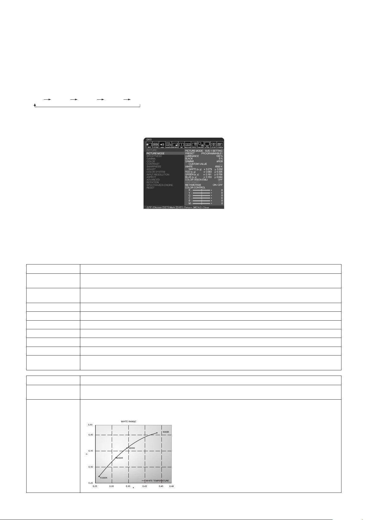
English-28
Picture Mode
Depending on the setting of SPECTRAVIEW ENGINE in the OSD PICTURE (see page 34), the selection choices for the Picture
Mode are different.
SPECTRAVIEW ENGINE is set to “ON”:
Select from five different picture modes, either via the OSD menu item PICTURE MODE, or using the PICTURE MODE button
on the wireless remote control.
Select the Picture Mode with the wireless remote control
By pressing the Picture Mode button, the picture mode changes.
SVE-1
SVE-2 SVE-3 SVE-4 SVE-5
Select or change the Picture Mode in the OSD menu item PICTURE MODE
Select a setting from SVE-1 SETTING to SVE-5 SETTING at PICTURE MODE.
Select a preset item at PRESET.
Choose the Picture Mode that is most suitable for the type of content that is shown.
•Several modes are selectable (sRGB, Adobe
®
RGB SIM., eciRGB_v2 SIM., DCI SIM., REC-Bt709, HIGH BRIGHT, FULL,
DICOM SIM, PROGRAMMABLE).
•EachPICTUREMODEincludesLUMINANCE,WHITE,GAMMA,BLACK,RED,GREEN,BLUE,COLORVISIONEMU,
UNIFORMITY and METAMERISM settings.
PRESET Types
PRESET PURPOSE
sRGB
The standard color space used for the Internet, Windows
®
operating systems and digital cameras.
Recommended setting for general color management.
Adobe
®
RGB SIM.
Provides a standard color space used in high-end graphics applications such as professional digital still cameras and
imaging.
eciRGB_v2 SIM.
Provides a color space profile recommended by ECI (The European Color Initiative).
DCI SIM.
Color setting for digital cinema.
REC-Bt709
Color setting for High-definition television.
HIGH BRIGHT
Highest brightness setting.
FULL
Native LCD panel color gamut. Suitable for use with color managed applications.
DICOM SIM.
Setting that conforms to the DICOM standard for the Grayscale Standard Display Function.
PROGRAMMABLE
For the Hardware Calibration by NEC Display Solutions GammaCompMD QA software (some OSD settings are
disabled).
MODE PURPOSE
LUMINANCE Adjusts the overall image and screen background brightness.
Press “LEFT” or “RIGHT” to adjust.
WHITE Adjusts the white color by temperature or x, y setting. A lower color temperature will result in a reddish screen and a
higher color temperature in a bluish screen. A larger x value will result in a reddish screen, a larger y value changes
the screen to greenish, and smaller x,y values will change the screen to bluish white.
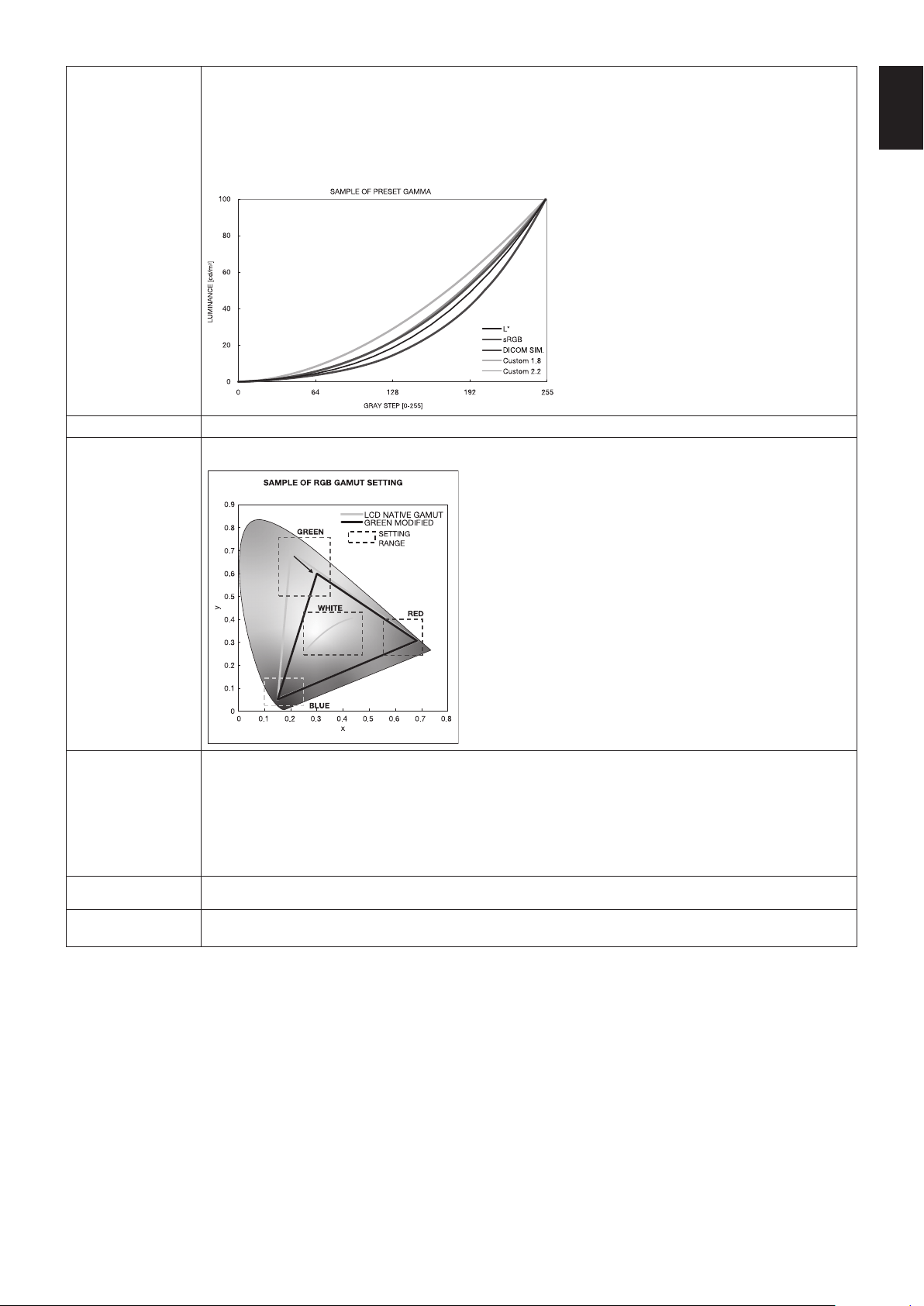
English-29
English
GAMMA Allows you to manually select the brightness level of grayscale. There are five selections: sRGB, L STAR,
DICOM SIM. and CST. We recommend to show grayscale image data on screen.
sRGB: GAMMA setting for sRGB.
L STAR: GAMMA setting for the CIELAB color space Lab.
DICOM SIM.: DICOM GSDF (Grayscale Standard Display Function) is typically used for medical imaging.
CST: CUSTOM VALUE can be adjusted when CST is selected as the GAMMA SELECTION setting.
CUSTOM VALUE: The gamma value is selected from the range from 0.5 to 4.0 in 0.1 steps.
BLACK Adjusts the black luminance.
RED
GREEN
BLUE
Adjusts the color gamut.
COLOR VISION EMU Previews various typical human vision deficiencies and is useful for evaluating how people who have such
deficiencies will perceive colors. This preview is available in four modes: Types P (Protanopia), D (Deuteranopia) and
T (Tritanopia) emulate color vision dichromacy, and Grayscale can be used for evaluating contrast legibility.
NOTE: Depending on the vision of the user, including those with color vision deficiency, there will be a variation in
how the screen's color is seen and experienced.
A simulation is used to illustrate the view of those with a color vision deficiency. It is not their actual view. The
simulation is a reproduction of those with a strong color vision mode of type P, type D or type T. People with a slight
color vision deficiency will experience little to no difference compared to those with normal color vision.
UNIFORMITY
(Not available)
METAMERISM Compensates the visual color difference with other monitors.
If you prefer to get the color reproduction to be closer to the Picture Mode setting, set this function to OFF.
NOTE: - When the selected PICTURE MODE is different from your computer’s ICC color profile, you may experience
inaccurate color reproduction.
- MultiProfiler software, developed by NEC Display Solutions, is highly recommended to provide extended color
management features such as ICC profile Emulation and Printer Emulation. The latest MultiProfiler software is
available on the NEC Display Solutions website.

English-30
SPECTRAVIEW ENGINE is set to “OFF”:
Select from five different picture modes, either via the OSD menu item PICTURE MODE, or using the PICTURE MODE button
on the wireless remote control.
For DVI, DisplayPort1, DisplayPort2, OPTION*, VGA (RGB), HDMI1, HDMI2, C MODULE*
2
STANDARD
sRGB CINEMA CUSTOM1 CUSTOM2 HIGHBRIGHT
*: This function depends on which option board you are using.
*
2
: This input is available when the optional Raspberry Pi Compute Module Interface Board and Raspberry Pi Compute Module are installed.
For VGA (YPbYr), VIDEO, MP
STANDARD CINEMA CUSTOM1 CUSTOM2 HIGHBRIGHT
PRESET types
PRESET PURPOSE
HIGH BRIGHT
Highest brightness setting.
STANDARD
Standard setting.
sRGB
The standard color space used for the Internet, Windows
®
operating systems and digital cameras. Recommended
setting for general color management.
CINEMA
A setting that boosts dark tones; best suited for movies.
CUSTOM
Custom setting.
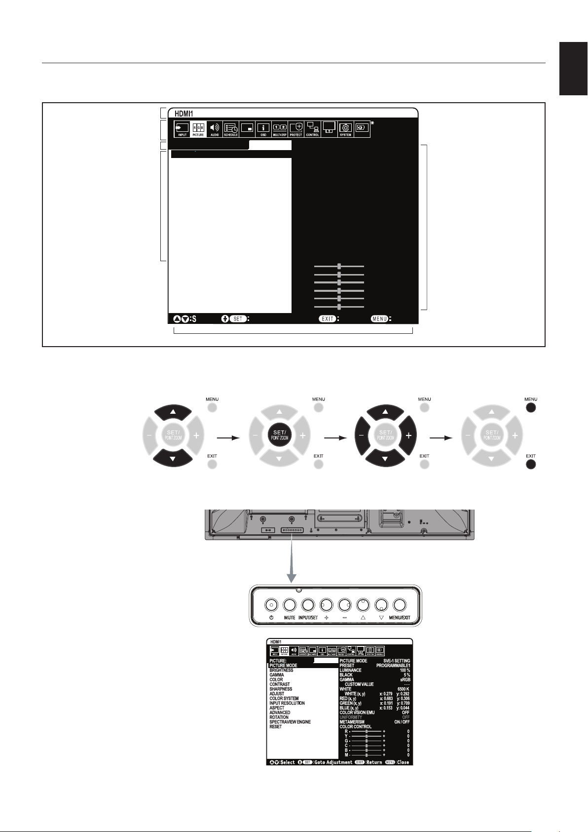
English-31
English
OSD (On-Screen-Display) Controls
NOTE: Some functions may not be available depending on the model or optional equipment.
PICTURE:
PICTURE MODE
BRIGHTNESS
GAMMA
COLOR
CONTRAST
SHARPNESS
ADJUST
COLOR SYSTEM
INPUT RESOLUTION
ASPECT
ADVANCED
ROTATION
SPECTRAVIEW ENGINE
RESET
PICTURE MODE SVE-1 SETTING
PRESET PROGRAMMABLE1
LUMINANCE 100 %
BLACK 5 %
GAMMA sRGB
CUSTOM VALUE - - -
WHITE 6500 K
WHITE (x, y) x: 0.279 y: 0.292
RED (x, y) x: 0.683 y: 0.306
GREEN (x, y) x: 0.191 y: 0.709
BLUE (x, y) x: 0.153 y: 0.044
COLOR VISION EMU OFF
UNIFORMITY OFF
METAMERISM ON / OFF
COLOR CONTROL
R - + 0
Y - + 0
G - + 0
C - + 0
B - + 0
M - + 0
Goto Adjustment
Select
Return Close
C MODULE
*
MULTI-INPUT OPTION
Input source
Main Menu Icons
Main Menu Item
Sub Menu
Key Guide
Adjustment Settings
*: This menu is only available
when the optional Raspberry
Pi Compute Module Interface
Board and Raspberry Pi
Compute Module are installed.
Remote Control
Press UP or DOWN
to navigate to a
sub-menu.
Press SET/POINT
ZOOM to select an
option.
Press UP or DOWN,
PLUS or MINUS to select
the function or setting to
be adjusted.
Press MENU or EXIT.
Press UP or DOWN to
navigate to a sub-menu.
Press INPUT to
select an option.
Press UP or DOWN, PLUS
or MINUS button to select.
Press EXIT
Control Panel
OSD screen
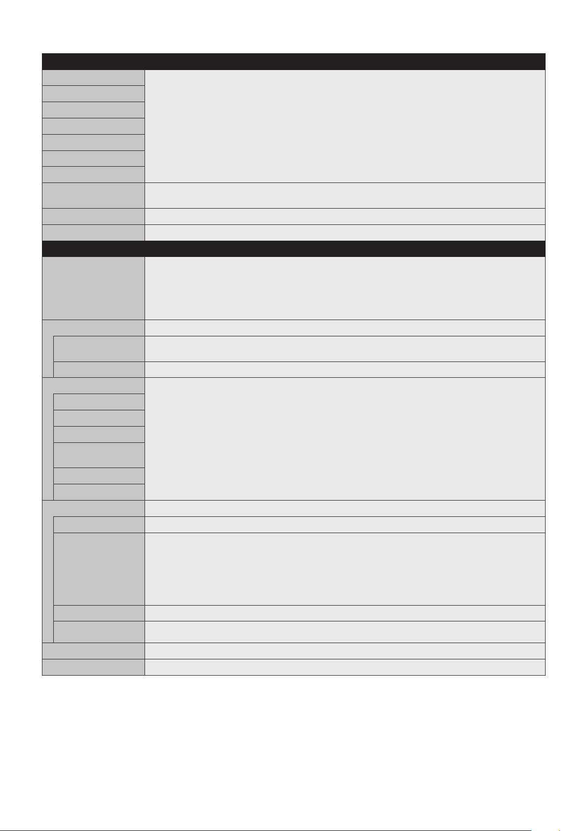
English-32
Setting
INPUT
DVI Select input signal.
HDMI1
HDMI2
DisplayPort1
DisplayPort2
VGA (RGB/YPbPr)
VIDEO
MP Displays images or movies saved in microSD memory card or USB storage device. Please refer to the Media
Player setting (See page 21).
COMPUTE MODULE*
5
Select input signal.
OPTION*
3
Select input signal.
PICTURE
PICTURE MODE Select picture mode:
SpectraView Engine = OFF: [HIGHBRIGHT], [STANDARD], [sRGB], [CINEMA], [CUSTOM1], [CUSTOM2].
SpectraView Engine = ON: [SVE-1 SETTINGS], [SVE-2 SETTINGS], [SVE-3 SETTINGS], [SVE-4 SETTINGS] or
[SVE-5 SETTINGS]. See page 28.
NOTE: If WHITE is set to NATIVE when the SPECTRAVIEW is ON, WHITE is not functioning.
To be able to set the CUSTOM VALUE, please set CST at GAMMA.
BRIGHTNESS*
1
BACKLIGHT Adjusts the overall image and background brightness. Press + or - to adjust.
NOTE: When MODE1 or MODE2 is selected in ROOM LIGHT SENSING, this function cannot be changed.
BRIGHTNESS*
2
Adjusts the image brightness in relationship to the background. Press + or - to adjust.
GAMMA*
1,
*
2
Select a monitor gamma correction for best picture quality. Selection depends on the desired usage.
NATIVE Gamma correction is handled by the LCD panel.
2.2 Typical monitor gamma for use with a computer.
2.4 Good for video (DVD, etc.)
S GAMMA Special gamma for certain types of movies. Raises the dark parts and lowers the light parts of the image
(S-Curve).
DICOM SIM. DICOM GSDF curve simulated for LCD type.
PROGRAMMABLE1, 2, 3
A programmable gamma curve can be loaded using optional NEC software.
COLOR*
2
COLOR Adjusts the color depth of the screen. Press + or - to adjust.
COLOR
TEMPERATURE*
1
Adjusts the color temperature of the entire screen. A low color temperature will result in a reddish screen. A high
color temperature will make the screen bluish. If TEMPERATURE needs further adjustment, the individual R/G/B/
levels of the white point can be adjusted. To adjust the R/G/B levels, set CUSTOM as COLOR TEMP selection.
NOTE: Predefined 6500k is set as picture mode, a color temperature of 6500k is predefined so it cannot be
changed.
When PROGRAMMABLE1, PROGRAMMABLE2 or PROGRAMMABLE3 is selected in GAMMA CORRECTION,
this function cannot be changed.
COLOR CONTROL Adjusts the hue of the Red, Yellow, Green, Cyan, Blue and Magenta.
HUE*
4
MP, VIDEO inputs only
Adjusts the hue of the screen. Press + or - to adjust.
CONTRAST*
1,
*
2
Adjusts the image brightness in relationship to the input signal. Press + or - to adjust.
SHARPNESS*
1
Adjusts the crispness of the image. Press + or - to adjust.
*1: If SPECTRAVIEW ENGINE is ON, this function is grayed out.
*2: This function is not available when sRGB is selected at PICTURE MODE.
*3: When you select OPTION for signal input, this function depends on which option board you are using.
*4: This function is not available for still image by MP input.
*5: This function is only available when Raspberry Pi Compute Module Interface Board and Raspberry Pi Compute Module are installed.
English-33
English
ADJUST
AUTO SETUP
VGA (RGB) input only
Automatically adjusts Screen Size, H position, V position, Clock, Phase and White Level.
AUTO ADJUST
VGA (RGB) input only
H Position, V Position and Phase are adjusted automatically when new timing is detected.
H POSITION
VGA (RGB), VGA (YPbPr) inputs only
Controls the horizontal position of the image within the Display area of the LCD.
Press + to move right. Press - to move left.
V POSITION
VGA (RGB), VGA (YPbPr) inputs only
Controls the vertical position of the image within the Display area of the LCD.
Press + to move up. Press - to move down.
CLOCK
VGA (RGB) input only
Press + to expand the width of the image on the right of the screen.
Press - to narrow the width of the image on the left.
PHASE
VGA (RGB), VGA (YPbPr) inputs only
Adjusts the visual “noise” on the image.
H RESOLUTION*
1
VGA (RGB) input only
Adjusts the horizontal size of the image.
V RESOLUTION*
1
VGA (RGB) input only
Adjusts the vertical size of the image.
COLOR SYSTEM
VIDEO input only
The selected Color System depends on the video format of the input signal.
AUTO
NTSC Automatically chooses Color System setting based on input signal.
PAL
SECAM
4.43 NTSC
PAL-60
INPUT RESOLUTION
VGA (RGB) input only
If there is a problem with signal detection, this function forces the monitor to display the signal at the desired
resolution. After selection, execute “AUTO SETUP” if required.
If no problem is detected, the only available option will be “AUTO”.
ASPECT Select the aspect ratio of the screen image.
NOTE: When the ASPECT is set to DYNAMIC, the image will be changed to FULL image before IMAGE FLIP,
and then start IMAGE FLIP.
When the ASPECT is DYNAMIC or ZOOM, the image will be changed to FULL image before TILE MATRIX, then
start to TILE MATRIX. After TILE MATRIX, the ASPECT will be returned to be previous ASPECT or set ASPECT
during TILE MATRIX.
If you change H POSITION and V POSITION settings with a reduced image, the image would not be changed.
If SCREEN SAVER is set, the ASPECT setting automatically changes to FULL from what you set. Once SCREEN
SAVER is off the ASPECT setting will go back to the setting that you originally set.
This function is not available when MOTION in SCREEN SAVER is active.
When the ASPECT is set to DYNAMIC or ZOOM while TILE MATRIX is set to active, after releasing
TILE MATRIX, DYNAMIC or ZOOM will be active.
POINT ZOOM function has limitations, please refer to POINT ZOOM (See page 58).
Zoom is also not available for an image with input resolution a 3840 x 2160 (60 Hz).
NORMAL Shows the aspect ratio as it is sent from the source.
FULL Fills the entire screen.
WIDE Expands a 16:9 letterbox signal to fill the entire screen.
DYNAMIC Expands 4:3 pictures to fill the entire screen with non-linearity image. Part of the outside image area will be cut
off due to expansion.
1:1 Shows the image in a 1 by 1 Pixel format. (If the input resolution is higher than the recommended resolution,
the image will be scaled down to fit the screen).
ZOOM Expands/reduces the image.
NOTE: The areas of the expanded image that are outside of the active screen area are not shown. The reduced
image may have some image degradation.
ZOOM Maintains the aspect ratio while zooming.
HZOOM Horizontal zoom value.
VZOOM Vertical zoom value.
H POS Horizontal position.
V POS Vertical position.
*1: After setting this item individually, we recommend to run AUTO SETUP.
English-34
ADVANCED
OVER SCAN
HDMI1, HDMI2, VGA (YPbPr), VIDEO, MP,
OPTION*
1
inputs only
Some video formats may require different scanning modes in order to best display the image.
ON Image size is larger than what can be displayed. The image edge will appear cropped.
Approximately 95% of the image will be shown on the screen.
OFF Image size stays within the display area. The whole image is displayed on the screen.
NOTE: When you use a computer with HDMI out, please set “OFF”.
AUTO Image size is set automatically.
NOTE: This function is not available if input signal is VGA (YPbPr), VIDEO or MP.
DEINTERLACE Selects the IP (Interlace to Progressive) conversion function.
NOTE: IMAGE FLIP is not available. When SUPER is selected in INPUT CHANGE and displayed, this function
cannot be changed.
ON Converts interlaced signals to progressive. This is the default setting.
OFF Disables IP conversion. This setting is best suited for motion pictures, but increases the risk of image retention.
NOISE REDUCTION
VIDEO input only
Adjusts the amount of noise reduction. Press + or - to adjust.
TELECINE
HDMI1, HDMI2, VIDEO, VGA (YPbPr),
MP inputs only
Automatically senses the sources frame rate for optimal picture quality.
NOTE: Set DEINTERLACE ON if TELECINE is AUTO.
ADAPTIVE
CONTRAST*
2
HDMI1, HDMI2, VIDEO, VGA (YPbPr),
MP inputs only
Sets the level of adjustment for dynamic contrast.
If HIGH is set, the image is displayed clearly but it makes brightness unstable due to the wide gap of contrast
variation.
ROTATION Shows the inverse image right-left, up-down or rotation.
Press + or - to select.
NOTE: This function is not available when MOTION in SCREEN SAVER is “ON”.
IMAGE FLIP NOTE: When the ASPECT is set to DYNAMIC, the image will be changed to FULL image before ROTATE starts,
then ROTATE will start to work.
When selecting IMAGE FLIP (except for NONE), the following functions are disabled: MULTI PICTURE MODE,
TEXT TICKER, STILL, POINT ZOOM and TILE MATRIX.
When the input signal is interlaced, the image may be disturbed.
NONE
Normal mode.
H FLIP
The image inverts right-left.
V FLIP
The image inverts up-down.
180°ROTATE
The image rotates 180 degrees.
OSD FLIP Determines the OSD display direction.
If “ON” is selected, the OSD will be inverted depending on the image status.
SPECTRAVIEW ENGINE Select “ON” to activate SPECTRAVIEW ENGINE (see page 28).
RESET Resets all “PICTURE” settings back to factory settings except for SPECTRAVIEW ENGINE and PICTURE
MODE.
AUDIO
VOLUME Increase or decrease output volume level.
BALANCE
BALANCE Select STEREO or MONO for the audio output.
If you select STEREO, adjust the L/R volume balance.
Press the + button to move the stereo sound image to right.
Press the - button to move the stereo sound image to left.
NOTE: BALANCE is not available if MONO is set at STEREO/MONO.
SURROUND Artificial surround sound.
NOTE: LINE OUT is disabled when this function is set to “ON”.
*1: This function depends on which option board you are using.
*2: If SPECTRAVIEW ENGINE is ON, this function is grayed out.
English-35
English
EQUALIZER
TREBLE Accentuate or reduce the high frequency range of audio signals.
Press the + button to increase TREBLE.
Press the - button to decrease TREBLE.
BASS Accentuate or reduce the low frequency sound.
Press the + button to increase BASS.
Press the - button to decrease BASS.
AUDIO INPUT Selects the audio input source: [DVI], [HDMI1], [HDMI2], [DisplayPort1], [DisplayPort2], [IN1], [IN2], [VIDEO],
[MP], [OPTION]*
1
.
MULTI PICTURE AUDIO Selects audio source.
NOTE: This function depends on MULTI PICTURE setting.
LINE OUT Selecting VARIABLE enables control of the line out level with the VOLUME button.
AUDIO DELAY
AUDIO DELAY Activate a delay time to output the audio signal. The DELAY TIME can be set between 0 and 100 milliseconds.
Set to ON to activate this function.
DELAY TIME
RESET Resets all AUDIO options back to factory settings, except for VOLUME.
SCHEDULE
SCHEDULE SETTINGS Creates a working schedule for the monitor.
Press the , +, - buttons to navigate and change the schedule settings. Press the SET/ZOOM on the remote
or Input change buttons on the monitor to select settings.
NOTE: Please set DAY & TIME before configuring the SCHEDULE SETTINGS.
When the SCHEDULE SETTINGS window is closed, any schedules that you set are saved.
If schedules are set for the same time, higher SETTINGS numbers are given the priority.
If OFF TIMER is ON, SCHEDULE SETTINGS is not available.
When you select an invalid input signal or picture mode, it will display in red. While the SCHEDULE SETTINGS
window is open, schedules are not operated. Also, see page 45.
SETTINGS Set ON to activate the schedule. Maximum 30 schedules are set.
POWER Setting for the monitor power. Please set ON or OFF for each schedule.
TIME Set the schedule operation time. If there is no specific time for the schedule set [--].
INPUT Set the input signal for the schedule. To keep the input signal that is active when the schedule starts set [--].
When you set INPUT, please select ON at POWER.
PIC. MODE Set the picture mode for the schedule. To keep the picture mode that is active when the schedule starts set [--].
When you set PIC. MODE, please select ON at POWER.
Select one item from below (only one item is available).
DATE Select this setting if the schedule is for one day schedule or irregular schedules.
EVERY DAY Select this setting if the schedule is repeating every day.
EVERY WEEK Select this setting if the schedule is repeating every week.
WEEKDAY Select this setting if the schedule is on a weekday.
This item is set by the WEEKEND and the HOLIDAY settings. A day, which is not selected at WEEKEND and
HOLIDAY settings is set as a weekday.
WEEKEND Select this setting if the schedule is on a weekend.
Schedule operates on the date that is set at WEEKEND SETTINGS.
HOLIDAY Schedule operates on the date that is set at HOLIDAY SETTINGS.
SCHEDULE LIST List of working schedules. Displays up to 30 schedules.
HOLIDAY SETTINGS
No. Creates holiday schedule for the monitor.
YEAR
MONTH
DAY
WEEK
Set YEAR and MONTH.
Select DAY or WEEK.
DAY: Set a day.
WEEK: Set a week and the day of the week.
If you set [--] at MONTH or YEAR, every month or year of the day you select is set as a holiday.
END DAY Set the end of holiday date. If you schedule beyond a year, please separate the schedule per year.
NOTE: If DAY is not set, END DAY is not available. If your holiday setting includes [--] for year or month, END
DAY is not available.
SET/DELETE Sets or deletes a schedule.
WEEKEND SETTING
WEEKEND Set the day of the week.
*1: This function depends on which option board you are using.
English-36
DATE & TIME Sets the date, time, and daylight savings region. Date & time must be set in order for the “SCHEDULE” function
to operate.
NOTE: If the monitor’s main power has been turned off for two weeks, the DATE & TIME setting goes back to the
default setting and the clock function stops working.
YEAR Sets the year for the real-time clock.
MONTH Sets the month for the real-time clock.
DAY Sets the day for the real-time clock.
TIME Sets the time for the real-time clock.
CURRENT DATE TIME Shows the current date and time.
DAYLIGHT SAVING Sets daylight savings on or off.
NOTE: Please set the TIME & DATE setting first if you change the DAYLIGHT SAVING setting.
DAYLIGHT SAVING If ON is selected, please set daylight savings settings below.
BEGIN MONTH Set daylight savings beginning date.
END MONTH Set daylight savings ending date.
TIME DIFFERENCE Set the time difference.
OFF TIMER Set the monitor to power off after a preset time period. A time period between 1 to 24 hours may be set.
NOTE: SCHEDULE is not available if OFF TIMER is ON.
RESET Resets the following settings within the SCHEDULE menu back to factory setting: DATE & TIME and DAYLIGHT
SAVING.
MULTI INPUT
KEEP MULTI PICTURE
MODE*
1
Allows the monitor to remain in MULTI PICTURE and TEXT TICKER mode after powering off.
When Power is returned, MULTI PICTURE and TEXT TICKER appear without having to enter the OSD.
MULTI PICTURE
MODE*
1,
*
3
MULTI PICTURE When “OFF” is selected, one picture is displayed.
When “ON” is selected, several pictures are displayed. Select PIP or PBP.
NOTE: When “ON” is selected, TEXT TICKER, CLOSED CAPTION, TILEM ATRIX, MOTION in SCREEN
SAVER, IMAGE FLIP, except for NONE, INPUT SUPER in INPUT CHANGE is released.
ACTIVE PICTURE*
1,
*
2
ACTIVE When MULTI PICTURE is “OFF”, [PICTURE 1] is the Active Picture. When MULTI PICTURE is “ON”, sets Active
Picture.
NOTE: This function depends on MULTI PICTURE setting.
ACTIVE FRAME The active picture is shown within a red frame.
INPUT SELECT*
1,
*
2,
*
3
Selects the Multi Picture input. Press the + button or - button to select the input.
NOTE: This function is not available when MULTI PICTURE is “OFF”.
When changing input signal for the active picture, after selecting an input press SET.
PICTURE1
PICTURE2
PICTURE SIZE*
1,
*
2,
*
4
Sets the Active Picture size.
Press the SET/POINT ZOOM button to adjust the picture size. Press + or CH+ to expand. Press - or CH- to
reduce.
PICTURE POSITION*
1,
*
2,
*
4
Sets the Active Picture location.
Pressing the + button moves the Active Picture to the right, and pressing the - button moves it to the left.
Pressing the
button moves the Active Picture up, and pressing the button moves it down.
PICTURE ASPECT*
1,
*
2,
*
4
Selects the Active Picture frame aspect.
To change aspect ratio of the screen image, see page 20.
TEXT TICKER*
1,
*
3
NOTE: When TEXT TICKER is set, MULTI PICTURE MODE and STILL are not available.
TEXT TICKER is released if following menu is activated: MULTI PICTURE MODE, TILE MATRIX, SCREEN
SAVER, IMAGE FLIP, SUPER in INPUT CHANGE, CLOSED CAPTION.
When this function is active, POINT ZOOM and STILL are not available.
MODE Enables Text Ticker and allows you to set Horizontal or Vertical direction.
POSITION Selects the location of the Text Ticker on the screen.
SIZE Determines the size of the Text Ticker in relationship to the overall screen size.
DETECT Enables auto-detection of the Text Ticker.
INPUT SELECT Set input signal for PICTURE1, PICTURE2.
*1: This function is released when selecting SUPER in INPUT CHANGE, MOTION in SCREEN SAVER, TILE MATRIX and IMAGE FLIP except for NONE.
*2: When TEXT TICKER is active or multi picture is OFF, this function is not available.
*3: When you select OPTION for multi picture input, this function depends on which option board you are using.
*4: This function is not available if PIP is set at MULTI PICTURE MODE and then PICTURE1 is set at ACTIVE PICTURE.
English-37
English
INPUT DETECT Selects the method of input detection the monitor uses when more than one signal source is connected.
NOTE: When SUPER is selected within INPUT CHANGE, this function cannot be changed.
INPUT DETECT is released if HUMAN SENSOR is activated while INPUT DETECT is active.
NONE The Monitor will not search for signals at the other video input ports.
FIRST DETECT*
1,
*
2
When the current video input signal is not present, the monitor searches for a video signal from another video
input port. If a video signal is present in the other input, the monitor switches from the current video source to this
active video source automatically.
The monitor will not look for any other video signals while the current video source is present.
LAST DETECT*
1,
*
2
When the monitor is reproducing a signal from the current video source and a new second video source is supplied
to the monitor, the monitor will automatically switch to the new video source. When the current video input signal is
not present anymore, the monitor searches for a video signal from any other video input. If a video signal is present
in the other input, the monitor switches from the current video source to this active video source automatically.
CUSTOM DETECT*
1
Sets the priority of input signals. e.g. In the priorities, a signal input set to PRIORITY 1 has the highest priority.
When CUSTOM DETECT is selected, the monitor searches on preset inputs only.
NOTE: Priority of an option input signal is only available in PRIORITY3, except for a slot 2 type PC option.
If you set DisplayPort1 to Priority 1 or 2 or 3, you cannot set OPTION (slot 2 type PC option (DP)) to any priority
settings. If you set OPTION (slot 2 type PC option (DP)) to Priority 1 or 2 or 3, you cannot set DisplayPort1 to any
priority settings.
INPUT CHANGE Sets input change speed. If “QUICK” is set, speed of changing input gets faster but this setting occurs image
noise while switching signals.
The selection SUPER enables high-speed switching between two preset signals.
NOTE: It depends on the option board you use, SUPER is not available.
When “SUPER” is active, MULTI PICTURE MODE, TEXT TICKER, STILL, POINT ZOOM are not available.
TERMINAL SETTINGS
DVI MODE Selects the kind of DVI-D equipment, which is connected to the DVI input.
Select “DVI-HD” when a DVD player or computer equipment is connected which requires HDCP authentication.
Select “DVI-PC” when computer equipment is connected which does not requires HDCP authentication.
VGA MODE Selects RGB or YPbPr for VGA input.
SYNC TYPE Selects a type of sync signal of VGA (RGB).
AUTO: Automatically identifies received sync signal type.
H/V SYNC: If the input signal is H/V SYNC then displayed image is unstable with AUTO setting, please set H/V
SYNC.
SOG: If the input signal is SOG then displayed image is unstable with AUTO setting, please set SOG.
NOTE: If VGA MODE is set to YPbPr, you cannot set SYNC TYPE.
DisplayPort Selects the DisplayPort mode [1.1a] or [1.2].
DisplayPort 1.1a is selected, SST is set automatically.
DisplayPort 1.2 is selected, set SST or MST.
DisplayPort 1.2 should be selected when using Multi-Stream Transport. Multi-Stream Transport requires the
corresponding display card. Contact your supplier for limitations of this function.
NOTE: MST is not available with DisplayPort2 signal input.
BIT RATE DisplayPort 1.1a is selected at DisplayPort, HBR is set automatically.
DisplayPort1.2 and SST are selected at DisplayPort, set HBR or HBR2.
DisplayPort1.2 and MST are selected at DisplayPort, HBR2 is set automatically.
EQUALIZER Compensates for the image degradation caused by using a long cable or devices. A higher number produces
high compensation.
SLOT2 Compensates for the image degradation from the slot 2 type option DisplayPort signal.
DisplayPort1 Compensates for the image degradation from DisplayPort1 signal.
HDMI Selects MODE1 or MODE2.
MODE1: Max resolution is 3840 x 2160 (30 Hz)
MODE2: Max resolution is 3840 x 2160 (60 Hz)
VIDEO LEVEL AUTO: Automatically sets input signals by adjusting connected equipment.
RAW: For computer settings. Show all input signals of 0-255 gray levels.
EXPAND: For audio-visual equipment settings. Expands the input signals from 16-235 gray levels to 0-255 gray
levels.
NOTE: This function is available only in HDMI or DisplayPort or OPTION and is selected at INPUT SIGNAL.
RESET Resets MULTI INPUT options back to factory settings, except for INPUT DETECT (priority of input signals only),
INPUT CHANGE (INPUT1 and INPUT2), INPUT SELECT, PICTURE ASPECT and BIT RATE.
*1: When you select OPTION for multi picture input, this function depends on which option board you are using.
*2: Except for MP.
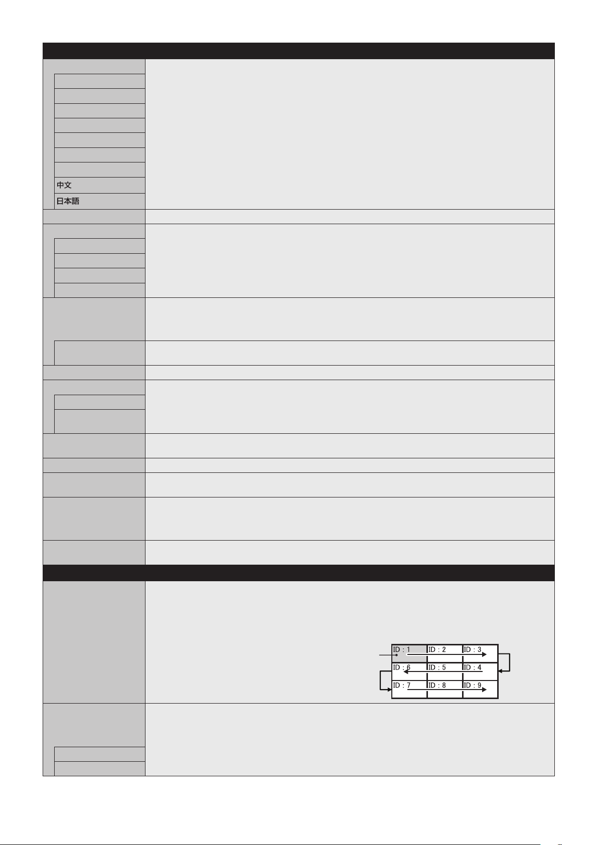
English-38
OSD
LANGUAGE Select the language used by the OSD.
ENGLISH
DEUTSCH
FRANÇAIS
ITALIANO
ESPAÑOL
SVENSKA
РУССКИЙ
OSD TIME Turns off the OSD after a period of inactivity. The preset choices are 10-240 seconds.
OSD POSITION Determines the location where the OSD appears on the screen.
UP
DOWN
RIGHT
LEFT
INFORMATION OSD Selects whether the Information OSD is displayed or not. The Information OSD will appear when the input signal
or input source changes. The Information OSD will also give a warning when no signal is detected or the signal is
out of range.
An interval between 3 to 10 seconds is selectable for the Information OSD to appear.
COMMUNICATION
INFO.
The MONITOR ID and IP ADDRESS will appear when the remote control Display button is pressed.
OSD TRANSPARENCY Selects the transparency of the OSD.
OSD ROTATION Determines the OSD orientation between landscape and portrait.
LANDSCAPE Shows the OSD in landscape orientation.
PORTRAIT Shows the OSD in portrait orientation.
NOTE: If PORTRAIT is set, CLOSED CAPTION is not available.
KEY GUIDE Key guide is shown when the OSD menu is displayed.
NOTE: This function is not available when OSD FLIP is “ON”.
MEMO Defines a title and a message via HTTP server. See page 55.
INPUT NAME You can create a name for the INPUT currently being used.
Max: 14 characters, including Space, A-Z, 0-9, and some symbols.
CLOSED CAPTION
VIDEO input only
Activates closed captioning.
NOTE: This function is released if the following function is activated: MULTI PICTURE MODE, TEXT TICKER,
PORTRAIT in OSD ROTATION, TILE MATRIX, SCREEN SAVER, STILL, POINT ZOOM, SUPER in INPUT
CHANGE.
RESET Resets the following settings within the OSD menu back to factory setting:
OSD TIME, OSD POSITION, INFORMATION OSD, OSD TRANSPARENCY, CLOSED CAPTION.
MULTI DISPLAY
AUTO TILE MATRIX
SETUP
TILE MATRIX allows one image to be displayed over multiple screens (up to 100) through a distribution amplifier.
Allows auto setting of TILE MATRIX by inputting the number of monitors arranged horizontally and vertically on
the primary monitor. Following settings are set automatically: MONITOR ID, TILE MATRIX, TILE MATRIX MEM,
Input Signal, VIDEO OUT SETTING, DisplayPort in TERMINAL SETTINGS.
NOTE: AUTO ID will be automatically executed. When you use this function, it is recommended that monitors be
chained by DisplayPort cable. This function is released if MOTION in SCREEN SAVER is activated.
Example of installation via LAN:
H MONITORS 3
V MONITORS 3
Primary monitor
SETTING COPY In a daisy chain scenario, select the OSD menu categories that you want to copy over to the other monitors.
NOTE: When you use this function, monitors should be daisy chained by LAN cables. This function will be reset
to default when power is off. This function has a limit in the number of connected monitors, depending on type
and quality of the LAN cable you use.
COPY START Select “YES” and press the SET button to start copying.
ALL INPUT All input terminals settings are copied when you select this item. Default is off.
English-39
English
TILE MATRIX Allows one image to be expanded and displayed over multiple screens (up to 100) through a distribution
amplifier.
NOTE: Low resolution is not suitable for tiling to a large number of monitors. You can operate without a
distribution amplifier at a lower number of screens.
This function is released when selecting SCREEN SAVER or IMAGE FLIP except for NONE.
Dynamic or Zoom will not work when Tile Matrix is activated.
When “DYNAMIC” or “ZOOM” is selected in ASPECT while executing TILE MATRIX, the setting will be applied
after completing the TILE MATRIX.
When TILE MATRIX is active the following functions are not available: MULTI PICTURE MODE, TEXT
TICKER, CLOSED CAPTION, STILL, POINT ZOOM. Please refer to the POINT ZOOM function for more detail
(see page 58).
If Media Player contents are played while TILE MATRIX is active, the image play timing might have a gap within
monitors.
This function is not available when SCREEN SAVER is active.
When HDMI of the TERMINAL SETTINGS is set to MODE2, TILE MATRIX is not available.
H MONITORS Number of monitors arranged horizontally.
V MONITORS Number of monitors arranged vertically.
POSITION Select which section of the tiled image to be displayed on the monitor.
TILE COMP Turns the TILE COMP feature on. If YES is set to the TILE COMP, you can adjust a displayed image size and
position by pressing the + button or the - button on the remote control.
ENABLE Enables the Tile Matrix settings.
TILE MATRIX MEM When “INPUT” is selected, the TILE MATRIX setting is applied to each signal input.
COMMON All settings in the TILE MATRIX are saved for all signal inputs.
INPUT All settings in the TILE MATRIX are saved for the selected signal input.
ID CONTROL Sets the monitor ID number from 1-100 and group ID from A-J. DETECTED MONITORS shows the number of all
monitors are included in the daisy chain of connected LAN cables.
NOTE: Do not turn off the monitors’ main power switch or put it into standby while AUTO ID/IP SETTING or
AUTO ID/IP RESET is activating.
The Group ID is made of multiple selections. Also see page 46.
AUTO ID/IP SETTING When “SET” is selected, AUTO ID/IP SETTING window is shown.
Do not connect network devices between the monitors connected with LAN.
SETTING ITEM Select an item from [MONITOR ID], [IP ADDRESS] and [ID and IP].
MONITOR ID When “YES” is set, monitor ID numbers are set automatically to the all monitors.
IP ADDRESS Set the first octet to the third octet at “BASE ADDRESS”.
The fourth octet is automatically set from “1” and counting up till the number of monitors connected with LAN.
“BASE ADDRESS” is shown when “IP ADDRESS” or “ID and IP” is selected at SETTING ITEM.
ID and IP Set “MONITOR ID” and “IP ADDRESS”.
BASE NUMBER Set base number within 100 for the master monitor.
The other monitors who follow in the chain with LAN will be given individual a monitor ID automatically. The
monitor ID given to the each monitor is counting up based on base number of the master monitor. Please set
base number by considering all monitor ID that given to the monitors following LAN also set within 100.
BASE ADDRESS When “YES” is set, monitor IP ADDRESS is set automatically to all monitors.
ID/IP SETTING
START
When “YES” is set, all the settings in the AUTO ID/IP SETTING are activated.
DETECTED
MONITORS
This item is shown after “SETTING ITEM” is selected and “ID/IP ADDRESS START” is set to “YES”.
If the shown number and actual monitor number, which MONITOR ID is given, are different, select “RETRY” to
recount monitors.
If the shown number is correct, set “CONTINUE”.
AUTO ID/IP RESET When “RESET” is selected, AUTO ID/IP RESET window is shown.
RESET ITEM Select a setting from [MONITOR ID], [IP ADDRESS], and [ID and IP].
When the number of monitors connected with LAN was changed, please select the same item that you selected
at “SETTING ITEM” in the AUTO ID/IP SETTING and then run the “AUTO ID/IP RESET”.
ID/IP RESET START When “YES” is set, the setting of selected item at RESET ITEM returns to default setting.
When the setting returns to default setting, “FINISH!!” is displayed.
NOTE: After “ID/IP RESET START” is activated, “MONITOR ID” and “IP ADDRESS” settings will be individual
settings even though monitors are connected with LAN.
DETECTED
MONITORS
Displays number of the detected monitors.
COMMAND
TRANSFER
When “ON” is set, a command is sent to the all monitors connected with LAN cables.
RESET Resets all settings within the MULTI DISPLAY menu back to factory setting.
English-40
DISPLAY PROTECTION
POWER SAVE Set ENABLE or DISABLE. If you set it to ENABLE, set how long the monitor waits to go into power save mode
after signal is lost. For more details, please check the Power Indicator (See page 42).
NOTE: The display card might not stop sending the digital data even though the image might have disappeared.
If this occurs the monitor will not switch into power management mode. POWER SAVE is disabled when AUTO
OFF or CUSTOM is selected in HUMAN SENSING*
3
.
AUTO POWER SAVE
TIME SETTING
Set the time when the monitor goes into auto power save mode after signal is lost.
POWER SAVE MESSAGE When the monitor goes into power save mode, a message is displayed when ON is selected.
FAN CONTROL Cooling fans will reduce the internal temperature of the monitor to protect from overheating.
If AUTO is selected, you can adjust the start temperature of the cooling fans and the fan speed.
HEAT STATUS Shows the actual status of the fans, backlight and temperature sensors.
SCREEN SAVER Use the SCREEN SAVER function to reduce the risk of Image Persistence.
NOTE: When the screen saver is activated, the image will be changed to FULL image. After the screen saver
stops, the image will be reproduced again with the current ASPECT setting.
The screen saver cannot be selected for 3840 x 2160 at 60 Hz signal input.
When the SCREEN SAVER is set to active, MULTI PICTURE MODE, STILL, IMAGE FLIP (except for NONE) or
TEXT TICKER, POINT ZOOM, TILE MATRIX, CLOSED CAPTION are not available.
GAMMA*
1
The monitor gamma is changed and fixed when “ON” is selected.
BACKLIGHT*
1
The brightness of the backlight is decreased when “ON” is selected.
NOTE: Do not select this function when ROOM LIGHT SENSING is set to MODE1 or MODE2.
MOTION*
2
The screen image is slightly expanded and moves in 4 directions (UP, DOWN, RIGHT, LEFT) at user determined
intervals. You can set interval time and zoom ratio.
SIDE BORDER COLOR Adjusts the color of the side borders when a 4:3 image is reproduced.
By pressing the + button on the remote control, the side borders will become brighter.
By pressing the - button, the side borders will become darker.
Background color of the Media Player window is also changed.
POWER ON DELAY Adjusts the delay time between being in “standby” mode and entering “power on” mode.
DELAY TIME “POWER ON DELAY” can be set between 0 and 50 seconds.
LINK TO ID When “ON” is selected, the delay time is linked with the Monitor ID. It takes more time when there are a large
number of IDs.
ALERT MAIL Set ON to activate alert mail. See page 53.
INTELLI. WIRELESS DATA Select “ON” to activate INTELLIGENT WIRELESS DATA function (see page 60). A password is required when
using the function.
RESET Resets all settings within the DISPLAY PROTECTION menu back to factory setting except for POWER ON
DELAY and INTELLI. WIRELESS DATA.
CONTROL
NETWORK INFORMATION
Shows the current network settings.
LAN NOTE: When changing any LAN settings, you need to wait several seconds until modified LAN settings are
applied.
IP SETTING Enabling this option automatically assigns an IP address to the monitor from your DHCP server.
Disabling this option allows you to enter a fixed IP address and subnet mask data obtained from your network
administrator.
NOTE: Consult your network administrator for the IP address when AUTO is selected for [IP SETTING].
IP ADDRESS Set your IP address for the monitor connected to the network when MANUAL is selected for [IP SETTING].
SUBNET MASK Set your subnet mask data for the monitor connected to the network when MANUAL is selected for
[IP SETTING].
DEFAULT GATEWAY Set your default gateway for the monitor connected to the network when MANUAL is selected for [IP SETTING].
NOTE: Enter [0.0.0.0] to delete the setting.
DNS Set the IP addresses of DNS servers.
AUTO: The DNS server, which is connected with the monitor, will automatically assign its IP address.
MANUAL: Manually enter the IP address of the DNS server which is connected with the monitor.
DNS PRIMARY Enter the primary DNS server settings of the network connected with the monitor.
NOTE: Enter [0.0.0.0] to delete the setting.
DNS SECONDARY Enter the secondary DNS server settings of the network connected with the monitor.
NOTE: Enter [0.0.0.0] to delete the setting.
*1: If SPECTRAVIEW ENGINE is ON, this function is grayed out.
*2: When you select OPTION for signal input, this function depends on which option board you are using.
*3: The function is available only when connecting the optional control unit.
English-41
English
CHANGE PASSWORD Allows the security password to be changed.
The factory preset password is 0000.
SECURITY
PASSWORD Input a security password.
SECURE MODE
OFF The security password is not required when the monitor power is on.
START-UP LOCK The security password is required when the monitor power is on.
CONTROL LOCK The security password is required when a remote control button or a control button on the monitor is pressed.
BOTH LOCK The security password is required when either the monitor is powered on, or a remote control button or a control
button on the monitor is pressed.
IR LOCK SETTINGS
Prevents the monitor from being controlled by the wireless remote control.
When ACTIVATE is selected, all settings are activated.
NOTE: IR LOCK SETTINGS is a function intended only for the wireless remote control buttons. This function
does not lock out access to the buttons on the monitor. To return to normal operation, press the “DISPLAY” button
on the remote control and hold it down for more than 5 seconds.
MODE SELECT
Selects the mode UNLOCK, ALL LOCK or CUSTOM LOCK.
UNLOCK
All buttons on the remote control are available for normal operation.
ALL LOCK
Locks all remote control buttons.
CUSTOM LOCK
Selects which buttons to be locked from POWER, VOLUME, and INPUT button.
Except for CUSTOM LOCK settings, other buttons on the remote control are locked.
POWER: When LOCK is selected, the POWER button is locked.
VOLUME: When UNLOCK is selected, set the minimum and maximum volume between VOL.0 to VOL.100.
VOLUME (+) button and VOLUME (-) buttons are only available from the minimum volume to the
maximum volume you set.
When LOCK is selected, VOLUME (+) button and VOLUME (-) buttons are locked.
INPUT: When UNLOCK is selected, choose up to three buttons from DVI, HDMI1, HDMI2, DisplayPort1,
DisplayPort2, VGA (RGB/YPbPr), VIDEO, MEDIA PLAYER, OPTION which you prefer to be
unlocked.
The unselected buttons are locked. When LOCK is selected, all INPUT buttons are locked.
CHANNEL: To lock channel buttons on the remote control, select it to LOCK then press ACTIVE, channel
CH/ZOOM (+) button and (-) button are locked.
KEY LOCK SETTINGS
Prevents the monitor from being controlled by buttons on the monitor.
When ACTIVATE is selected, all of the settings are activated.
NOTE: KEY LOCK SETTINGS is a function intended only for the buttons of the monitor. This function does not
lock out access to all buttons on the remote control. To activate the control key lock function, press the UP button
(
) and the DOWN button ( ) and hold down simultaneously for more than 3 seconds. To resume user mode,
press the UP button ( ) and the DOWN button ( ) and hold simultaneously for more than 3 seconds.
MODE SELECT
Selects the mode UNLOCK, ALL LOCK or CUSTOM LOCK.
UNLOCK
All buttons are available for normal operations.
ALL LOCK
Locks all remote control buttons.
CUSTOM LOCK
Selects which buttons to be locked from POWER, VOLUME, and INPUT button.
Except for CUSTOM LOCK settings, other buttons on the remote control are locked.
POWER: When LOCK is selected, the POWER button is locked.
VOLUME: When UNLOCK is selected, set the minimum and maximum volume between VOL.0 to VOL.100.
The PLUS button (+) and the MINUS button (-) are only available from the minimum volume to the
maximum volume you set.
When LOCK is selected, the PLUS button (+) and the MINUS button (-) are locked.
INPUT: When UNLOCK is selected, the INPUT/SET button is unlocked.
CHANNEL: To lock channel buttons on the remote control, select it to LOCK then press ACTIVE,
the UP button (
) and the DOWN button ( ) are locked.
DDC/CI
DisplayPort2, DVI, VGA (RGB) Inputs only
ENABLE/DISABLE: Turns ON or OFF the two-way communication and control of the monitor.
PING Confirm successful connection with the network by communicating with a preset IP address.
IP ADDRESS Sets an IP ADDRESS for sending PING.
EXECUTE Checks a reply can be sent to the monitor or not from the IP ADDRESS by sending PING.
IP ADDRESS RESET Resets IP ADDRESS SETTINGS back to factory settings.
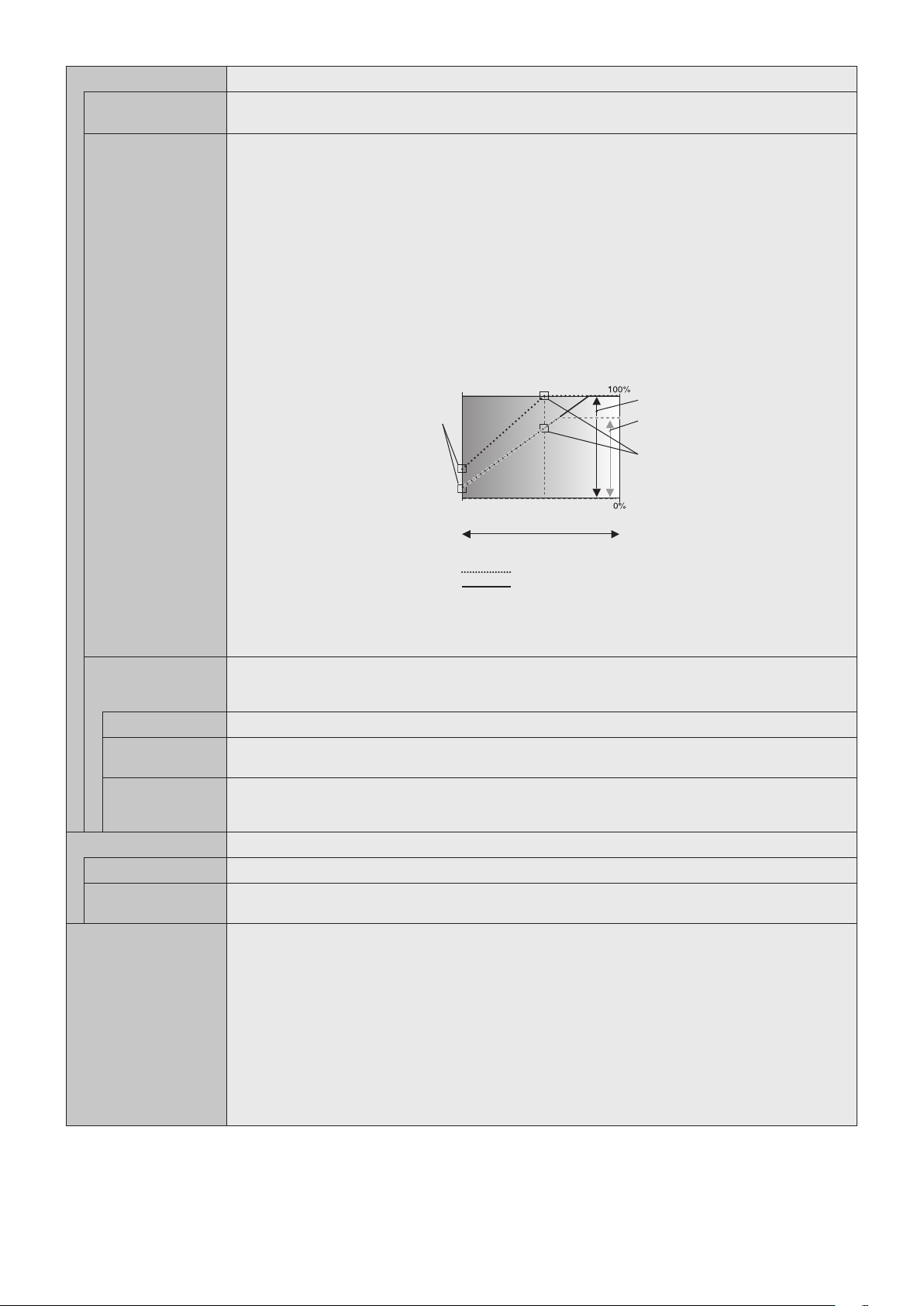
English-42
AUTO DIMMING*
1
Adjusts the backlight of the LCD automatically depending on the amount of ambient light.
AUTO BRIGHTNESS
DVI, DisplayPort1, DisplayPort2,
VGA (RGB), MP, OPTION*
3
inputs only
Adjusts the brightness level according to the input signal.
NOTE: Do not select this function when ROOM LIGHT SENSING is MODE1 or MODE2.
ROOM LIGHT
SENSING
The backlight of the LCD screen can be set to increase or decrease depending on the amount of ambient light
within the room. If the room is bright, the monitor becomes correspondingly bright. If the room is dim, then the
monitor will dim accordingly. The purpose of this function is to make the viewing experience more comfortable to
the eye in a variety of lighting conditions.
NOTE: When ROOM LIGHT SENSING is set, BACKLIGHT, AUTO BRIGHTNESS and BACKLIGHT in SCREEN
SAVER functions are disabled.
Do not cover the room light sensing sensor when you use MODE1 or MODE2.
AMBIENT parameter setting
ROOM LIGHT SENSING in OSD, select MODE1 or MODE2 and set MAX LIMIT, IN BRIGHT and IN DARK in
each mode.
MAX LIMIT: This is the max level of backlight, which you set.
IN BRIGHT: This is the backlight level that the monitor will go up to when the ambient light level is highest.
IN DARK: This is the level of backlight that the monitor will go down to when the ambient light level is low.
When the ROOM LIGHT SENSING is enabled the Backlight level of the screen changes automatically according
to the lighting conditions of the room (see figure below).
BACKLIGHT level set for
the monitor to use when
ambient lighting level is
low.
BACKLIGHT level set
for the monitor to use
when ambient lighting
level is high.
BACKLIGHT range
dark bright
room bright condition
Screen Backlight value by MODE2
IN DARK IN BRIGHT
Screen Backlight value by MODE1
Factory Setting
BACKLIGHT range when
set to MAX LIMIT.
MAX LIMIT: BACKLIGHT level is limited to your set level.
IN DARK: BACKLIGHT level set for the monitor to use when ambient lighting level is low.
IN BRIGHT: BACKLIGHT level set for the monitor to use when ambient lighting level is high.
HUMAN SENSING*
2
HUMAN SENSING has three settings.
NOTE: POWER SAVE is disabled when AUTO OFF or CUSTOM is selected in HUMAN SENSING.
HUMAN SENSING is released if INPUT DETECT is set while HUMAN SENSING is active.
DISABLE No human sensing.
AUTO OFF At the preset time, when no person is detected, BACKLIGHT and VOLUME automatically go into OFF. When a
person comes near the monitor again, the monitor will automatically return to normal mode.
CUSTOM BACKLIGHT and VOLUME automatically shift to the set value when detecting no person. When a person comes
near the monitor again, the monitor automatically returns to normal mode and reproduces the input signal
selected in INPUT SELECT.
POWER INDICATOR
POWER INDICATOR Turns the LED on or off. If OFF is selected, the LED will not glow when the LCD monitor is in active mode.
SCHEDULE
INDICATOR
Turns the LED on or off depending on a schedule activity which is set at “SCHEDULE SETTINGS”. If OFF is
selected, the LED will not glow even if a schedule is in active mode.
NETWORK FUNCTIONS Individually enable or disable the networking component for these monitor functions:
DISPLAY: Enables or disables the network function for controlling the monitor remotely.
When disabled, these functions do not work: External Control, Mail, Daisy chain functions, HTTP server, SNMP,
Crestron, AMX, PJLink.
NOTE: If you disable DISPLAY, monitor control in a daisy chain configuration is not available. Please be aware of
the impact in multi-monitor installations before disabling it.
COMPUTE MODULE: Enables or disables the network function for the Compute Module Interface Board only.
MEDIA PLAYER: Enables or disables the network function for the Media Player only.
When disabled, these functions do not work: SHARED FOLDER SETTINGS and SHARED SD CARD
SETTINGS.
Under APPLY, Highlight YES then press SET to save your selection. If you do not press SET when YES is
highlighted, your selections are not saved.
NOTE: To apply a firmware version update over the network, DISPLAY and MEDIA PLAYER must be enabled.
*1: If SPECTRAVIEW ENGINE is ON, this function is grayed out.
*2: The function is available only when connecting the optional sensor unit.
*3: When you select OPTION for signal input, this function depends on which option board you are using.
English-43
English
USB
TOUCH POWER Select “ON” to activate the touch panel function.
NOTE: Please refer to “The touch panel does not respond” in “Troubleshooting” when the touch panel function
does not work.
Select the input signal as follows:
Using slot 2 type PC: Select [OPTION].
Using external computer: Select the input signal which is supplied by the PC connected to USB connector.
EXTERNAL CONTROL When ON is set, the monitor is controlled by a device installed particular software which is connected to USB2.
PC SOURCE Select a control device which controls the monitor or touch panel function or USB device connected to USB1.
If a control device is specific, select EXTERNAL PC or OPTION.
OPTION is only available when slot 2 type PC option is connected to the monitor.
USB POWER Selects a power relation of USB CM1 (2A).
Set ON to supply the power to the USB CM1 (2A).
NOTE: Power consumption depends on which USB devices are connected to the monitor.
CEC This function enables you to control the HDMI CEC compliant device connected via HDMI connector.
CEC is an abbreviation of Consumer Electronics Control.
CEC When ON is set, please set items below.
NOTE: If ON is selected, the below functions are activated. Depending on the connected device, the device may
not work properly.
When the connected HDMI CEC device receives a play command, the monitor synchronously turns on then
changes the input signal to HDMI. If the monitor has been turned on, when a connected HDMI CEC device
receives a play command, input signal is switched to HDMI.
The connected HDMI CEC devices are controlled by the wireless remote control supplied with the monitor.
AUTO TURN OFF When the monitor goes to standby via remote control or the power button on the monitor, a connected HDMI
CEC device go to standby synchronously.
NOTE: If the connected HDMI CEC device is recording, the device does not go into standby.
AUDIO RECEIVER Activates HDMI CEC audio amplifier. If YES is set, outputs the sounds of the connected HDMI CEC device from
the connected HDMI CEC audio amplifier. If NO is set, the internal speaker or the HDMI CEC audio amplifier
connected to the monitor is set to mute.
NOTE: When an HDMI CEC audio amplifier is connected, set to YES.
Please set to NO if there is no connected HDMI CEC audio device to the monitor.
SEARCH DEVICE Searches the HDMI CEC device connected to the monitor. When search is successful, the connected HDMI CEC
device’s type and registered device name are shown. When search has been completed or failed, the SEARCH
DEVICE is set to NO automatically. To retry the SEARCH DEVICE, set it to YES again. After detecting HDMI
CEC devices, you can switch the device input by selecting the device.
RESET Resets all the settings within the CONTROL menu back to factory setting except for LAN, CHANGE
PASSWORD, SECURITY and PING.
OPTION
OPTION POWER Allows the monitor to supply power to an Option board slot during power save mode or standby mode.
AUTO: Power supply depends on whether or not an option board is connected.
ON: Supply power to the connected option continues during power save mode or standby mode.
OFF: Supply power to the connected option stops during power save mode or standby mode.
NOTE: To activate Power management function with no signal input from the inserted slot 2 type option, please
set OPTION POWER to AUTO or ON.
AUDIO*
1
Selects the sound input signal according to the slot2 type option specifications. To activate DIGITAL, select
OPTION for input signal and OPTION for AUDIO INPUT.
NOTE: DIGITAL is activated only when OPTION is selected for input signal and OPTION for AUDIO INPUT.
INTERNAL PC*
1
The function is available for a slot 2 type PC.
OFF WARNING
(Not adjustable)
AUTO OFF Monitor power is automatically OFF when the internal PC is OFF or the monitor is in power save mode.
NOTE: If you select OFF, the monitor power is not automatically ON when the internal PC is ON.
START UP PC When ON is selected, the internal PC will start.
FORCE QUIT When ON is selected, a forced shutdown of the internal PC will be carried out.
Please use this function only when the operating system cannot be shut down manually.
SLOT2 CH SETTING Selects signal type according to the slot 2 type option specifications.
AUTO Sets the signal type automatically.
1CH Fills the screen entirely with the signal which is selected in SLOT2 CH SELECT.
2CH The DisplayPort signal is displayed on the left half of the screen, the TMDS signal is displayed on the right
half. If the internal PC does not support either one of the signal types, the existing signal will automatically be
displayed on the full screen.
*1: This function depends on which option board you are using. When changing the setting, turn the monitor’s main power switch off and on again.
English-44
SLOT2 CH SELECT This function is available only when SLOT2 CH SETTING is 1CH.
DisplayPort Shows the DisplayPort signal from a slot 2 type PC option on the full screen.
TMDS Shows the TMDS signal from a slot 2 type PC option on the full screen.
RESET Resets the AUDIO setting back to the factory setting within the OPTION menu.
SYSTEM
MONITOR INFORMATION Shows the model name, serial number and firmware version of your monitor.
CARBON SAVINGS: Display the estimated carbon saving information in kg-CO2. The carbon footprint factor in
the carbon saving calculation is based on the OECD (2008 Edition).
CARBON USAGE: Display the estimated carbon usage information in kg-CO2. This is the arithmetic estimation,
not actual measurement value. This estimation is based without any options.
FIRMWARE Displays firmware version that is installed to the monitor.
MAC ADDRESS Displays the MAC ADDRESS.
FACTORY RESET All items are returned to factory shipment state.
NOTE: You can reset all items in all daisy chained monitors. Please be careful to avoid resetting all items
inadvertently.
COMPUTE MODULE
COMPUTE MODULE When a Raspberry Pi Compute Module Interface Board and Raspberry Pi Compute Module are installed,
additional OSD menu items will be available for configuring the related settings. Please do not change settings in
COMPUTE MODULE yourself.
POWER
POWER SUPPLY Controls power to the Compute Module.
AUTO POWER ON When set to Enable, power to the Compute Module will be turned on automatically when the display power is
turned on.
SERVICE MENU
SETTING LOCK Locks all settings under COMPUTE MODULE.
USB BOOT MODE When set to Enable, the Compute Module will appear as a USB device to a PC connected to the USB2 input on
the display and can be programmed with an Operating System. When set to Disable, the Compute Module will
boot normally.
IR SIGNAL Enables or disables the forwarding of IR remote control signals.
MONITOR CONTROL Enables or disables the internal serial connection between the display and Compute Module.
SHUTDOWN SIGNAL Enables or disables the use of GPIO 23 to signal that power to the compute module will be shutting down.
POWER SUPPLY
OFF DELAY
This sets the time delay after the Shutdown Signal is set until the power to the Compute Module is turned off.
Configure this to allow adequate time for any software to shutdown safely.
WDT Enables or Disables the display's built in Watchdog Timer function for the Compute Module.
START UP TIME This sets the time delay for when the display should start receiving WDT reset commands.
PERIOD TIME This sets the maximum amount of time within which the display must receive WDT reset commands from the
Compute Module.
CHANGE PASSWORD
Default values can be provided on request.
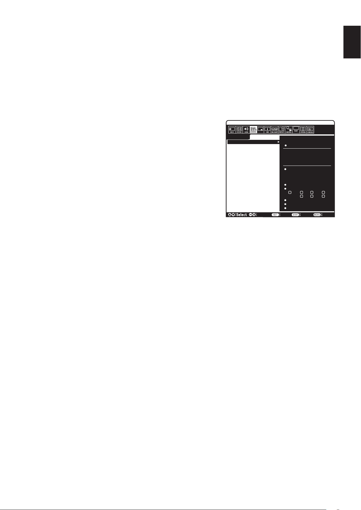
English-45
English
NOTE 1: CREATING A SCHEDULE
The schedule function allows the monitor to be set to power on or set it to be on standby at different times. Up to seven different schedules
can be programmed.
To program the schedule:
1. Enter the SCHEDULE menu. Highlight SCHEDULE SETTINGS using the up and down buttons. Press the SET/POINT ZOOM or the + button
to enter the Settings menu. Highlight the desired schedule number and press SET/POINT ZOOM. The box next to the number will turn yellow.
The schedule can now be programmed.
2. Use the down button to highlight the POWER. Use the + and - buttons to set ON. To set power off schedule, set OFF.
3. Use the down button to highlight the TIME. Use the + and - buttons to set the time.
4. Use the up and down arrows to highlight INPUT. Use the + and - buttons to choose the input source. Use the up and down arrows to highlight
PIC. MODE. Use the + and - buttons to choose the picture mode.
5. Use the down button to select DATE, EVERY DAY, EVERY WEEK, WEEKDAY,
WEEKEND or HOLIDAY. Push the SET/POINT ZOOM button on a menu which is
suitable for the schedule. If the schedule is to be run on specific day, choose DATE
and press the SET/POINT ZOOM button. If the schedule is to be run every day, choose
EVERY DAY and press the SET/POINT ZOOM button. The circle next to EVERY DAY
will turn yellow. If a weekly schedule is desired, choose the days of the week using the up
and down buttons and pressing SET/POINT ZOOM to select. Then highlight the EVERY
WEEK option and press SET/POINT ZOOM. Please set WEEKDAY, WEEKEND, or
HOLIDAY in the same manner.
For the WEEKDAY, WEEKEND, and HOLIDAY settings are available under the
SCHEDULE setting (See page 35).
6. After a schedule is programmed, the remaining schedules can then be set. Press MENU
to leave the OSD or press EXIT to go back to the previous menu.
NOTE: If schedules are overlapping, the schedule with the highest number will have
priority over the schedule with the lowest number. For example, schedule #7 will have
priority over schedule #1.
If a selected input or picture mode is not available now, the disabled input or picture mode is shown in red.
NOTE 2: IMAGE PERSISTENCE
Please be aware that LCD Technology may experience a phenomenon known as Image Persistence. Image Persistence occurs when a
residual or “ghost” image of a previous image remains visible on the screen. Unlike CRT monitors, LCD monitors’ image persistence is not
permanent, but a still image being displayed for a long period of time should be avoided.
To alleviate image persistence, turn off the monitor’s main power or set it to standby for as long as the previous image was displayed. For
example, if an image was on the monitor for one hour and a residual image remains, the monitor’s main power should be turned off or set it to
standby for one hour to erase the image.
As with all personal display devices, NEC DISPLAY SOLUTIONS recommends displaying moving images and using a moving screen saver at
regular intervals whenever the screen is idle, or turn off the monitor’s main power or set it to standby when not in use.
Please set “SCREEN SAVER”, “DATE &TIME” and “SCHEDULE SETTINGS” functions to further reduce the risk of Image persistence.
For long life use as a Public Display
Image Sticking of LCD Panel
When an LCD panel is operated continuously for long hours, a trace of electric charge remains near the electrode inside the LCD and a
residual or “ghost” image of the previous image may be observed. (Image Persistence)
Image Persistence is not permanent, but when a fixed image is displayed for long period, ionic impurities inside the LCD are accumulated
along the displayed image and may be permanent. (Image Sticking)
Recommendations
To prevent Image Sticking, and for longer life usage of the monitor, the following is recommended.
•Fixedimageshouldnotbereproduced for long period. Change still images after short intervals.
•Whennotinuse,pleaseturnoffthemonitorviaremotecontrol,orusethe Power Management function of the PC, or use the built-in Schedule
Functions.
•Lower environmental temperatures prolong the lifespan of the monitor.
When a protective surface (glass, acrylic) is installed over the monitor’s screen surface, the monitor’s screen surface is located in an
enclosure, or if the monitors are stacked, utilize the temperature sensors inside the monitor.
To reduce the internal temperature, use the Cooling Fans, Screen Saver, the Power Management function of the PC and Low Brightness.
•Pleaseuse“ScreenSaverMode”ofmonitor.
SCHEDULE:
POWER: ON
TIME: 04 : 03
DVI
INPUT:
PIC. MODE: STANDARD
DVI1
(MON) OCT.26.2015 12:37
SETTINGS:
SCHEDULE SETTINGS
SCHEDULE LIST
HOLIDAY SETTINGS
WEEKEND SETTINGS
DATE & TIME
DAYLIGHT SAVINGS
OFF TIMER
RESET
MONTH:
DAY:
1
Choose Mark
Return Close
DATE
YEAR:
JAN
01
2016
MON TUE WED THU
SAT SUNFRI
EVERY DAY
EVERY WEEK
HOLIDAY
WEEKDAY
WEEKEND
MULTI-INPUT OPTION
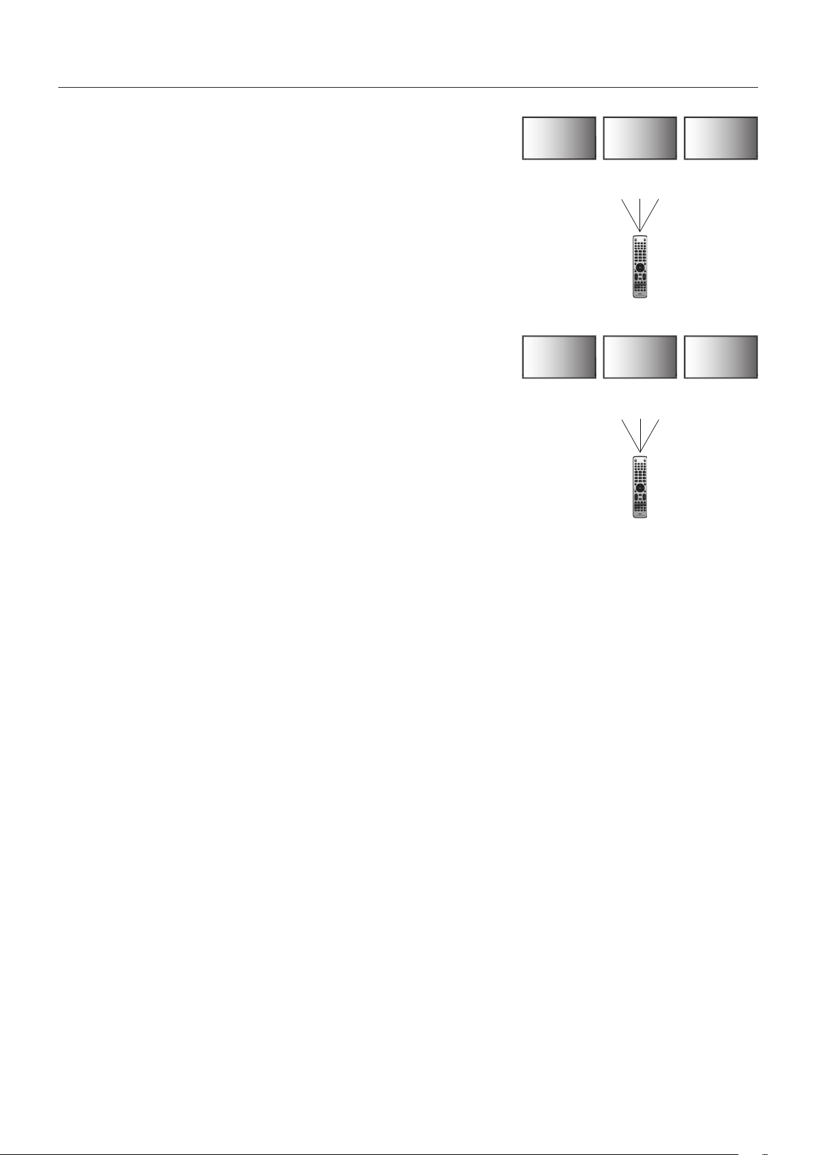
English-46
REMOTE CONTROL ID FUNCTION
REMOTE CONTROL ID
The remote control can be used to control up to 100 individual MultiSync monitors using
what is called the REMOTE CONTROL ID mode. The REMOTE CONTROL ID mode
works in conjunction with the Monitor ID, allowing control of up to 100 individual MultiSync
monitors. For example, if there are many monitors being used in the same area, a remote
control in normal mode would send signals to every monitor at the same time (see
Figure 1). Using the remote in REMOTE CONTROL ID mode will only operate one specific
monitor within the group (see Figure 2).
TO SET REMOTE CONTROL ID
While holding down the REMOTE ID SET button on the remote control, use the KEYPAD to
input the Monitor ID (1-100) of the monitor to be controlled via remote. The remote can then
be used to operate the monitor having that specific Monitor ID number.
When 0 is selected or when the remote control is in normal mode, all monitors will be
operated.
TO SET/RESET REMOTE CONTROL MODE
ID Mode - To enter ID Mode press the REMOTE ID SET button and hold down for
2 seconds.
Normal Mode - To return to Normal Mode press the REMOTE ID CLEAR button and hold
down for 2 seconds.
In order for this feature to work properly, the monitor must be assigned a unique Monitor ID
number. The Monitor ID number can be assigned under the MULTI DISPLAY menu in the
OSD (See page 39).
Point the remote control towards the remote sensor of the desired monitor and press the
REMOTE ID SET button. The MONITOR ID number is shown on the screen when your
remote control is in ID mode.
Use the remote to control all monitors in range
1. On the remote control, press and hold down the REMOTE ID SET button while using the keypad to input the REMOTE CONTROL ID
number “0”.
2. All monitors within range of the remote control will now respond to keypad press.
NOTE: When the REMOTE ID is set to “0”, pressing REMOTE ID SET will make all monitors, within range of the remote signal,
display their Monitor ID on screen. This way you can easily see what the monitor ID is if you want to control a single monitor,
as described below.
Use the remote control to operate a monitor that has a specific MONITOR ID number assigned to it.
1. Set the MONITOR ID number for the monitor (See page 39). The MONITOR ID number can range from 1-100.
This MONITOR ID number allows the remote control to operate this specific monitor without affecting other monitors.
2. On the remote control, press and hold down the REMOTE ID SET button while using the keypad to input the REMOTE CONTROL ID number
(1-100). The REMOTE ID NUMBER should match the MONITOR ID number of the monitor to be controlled.
3. Point the remote control towards the remote sensor of the desired monitor and press the REMOTE ID SET button.
The MONITOR ID number is shown in red on the monitor.
If the REMOTE CONTROL ID is “0”, then all monitors in range will show their respective MONITOR ID number in red.
If the MONITOR ID number is shown in white on the monitor, the MONITOR ID number and the REMOTE CONTROL ID are not the same.
NOTE: The GROUP ID cannot be specified via the remote control.
Remote Control Functions
Monitor ID:1 Monitor ID:2 Monitor ID:3
Monitor ID:1 Monitor ID:2 Monitor ID:3
Remote does
not work
Remote does
not work
Remote works
Remote works Remote works Remote works
Figure 1
Remote in
Normal mode or
the REMOTE ID
is set to 0
Figure 2
Remote set up
to use REMOTE
ID:3
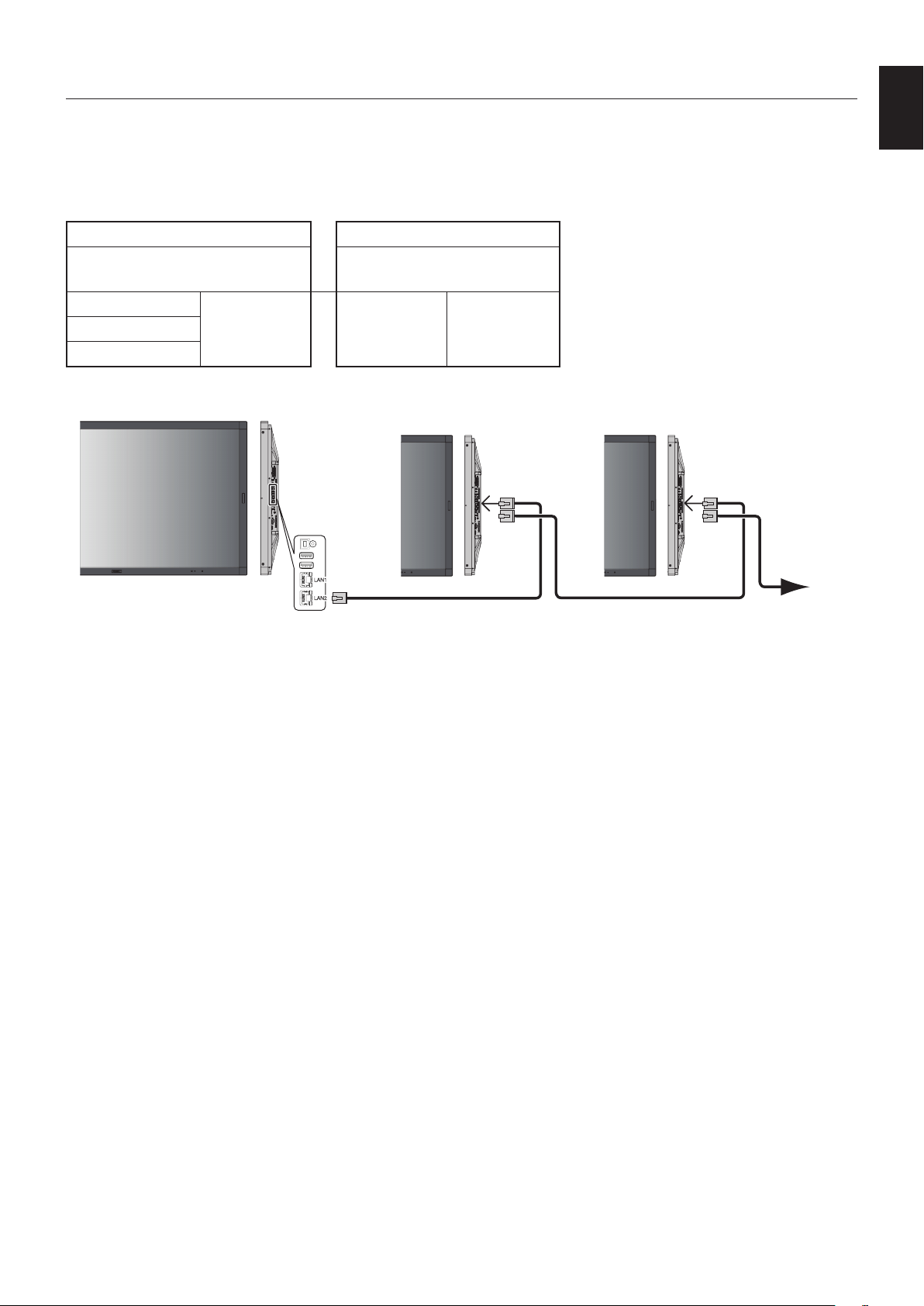
English-47
English
You can control multiple monitors by using RS-232C, REMOTE IN or LAN daisy-chain connection.
NOTE: Multiple monitors that are daisy-chained have a limit to the connectable monitors.
Please execute AUTO ID (see page 39) before manually specifying the ID number or control by the specified
ID number.
Main Monitor Sub Monitors
Connector Connector
IN OUT IN OUT
RS-232C
LAN2 LAN1 LAN2REMOTE IN
LAN1
Connection
LAN Cable LAN Cable
LAN1
LAN2
LAN1
LAN2
Next monitor
Multiple Monitors Connection
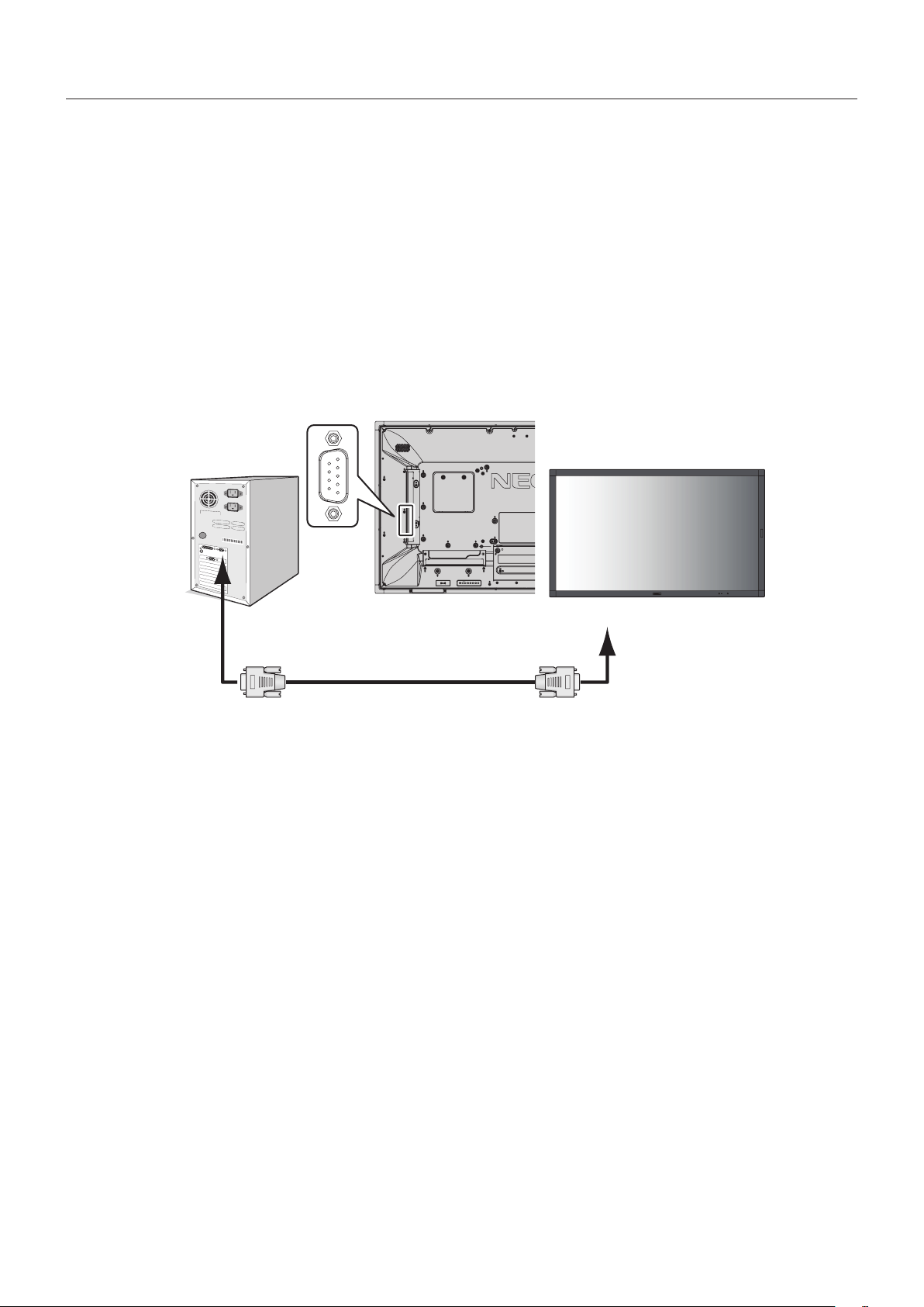
English-48
This LCD monitor can be controlled by connecting a personal computer with an RS-232C (reverse type) terminal.
Functions that can be controlled by a personal computer are:
•PowerONorstandby.
•Switchingbetweeninputsignals.
•SoundMuteONorOFF.
Connection
LCD Monitor + computer.
•Please turn off the monitor’s main power when connecting a computer to the monitor.
•Please turn on the connecting computer first then turn on the monitor’s main power.
If you turn on the computer and monitor in reverse order, the com port may not work.
•When controlling the monitor connected with an RS-232C cable, please refer to the Control command diagram (See page 56)
or see the “External_Control.pdf” file on the CD-ROM supplied with the monitor.
RS-232C Cable
Computer
RS-232C
NOTE: If your computer is equipped only with a 25-pin serial port connector, a 25-pin serial port adapter is required. Contact
your supplier for details.
For the pin assignment, please see “2) RS-232C input/output” on page 49.
To control a monitor, please use the control command. Instructions for the control command can be found on the CD included
with the monitor. The file is called “External_control.pdf”.
Controlling the LCD monitor via RS-232C Remote Control
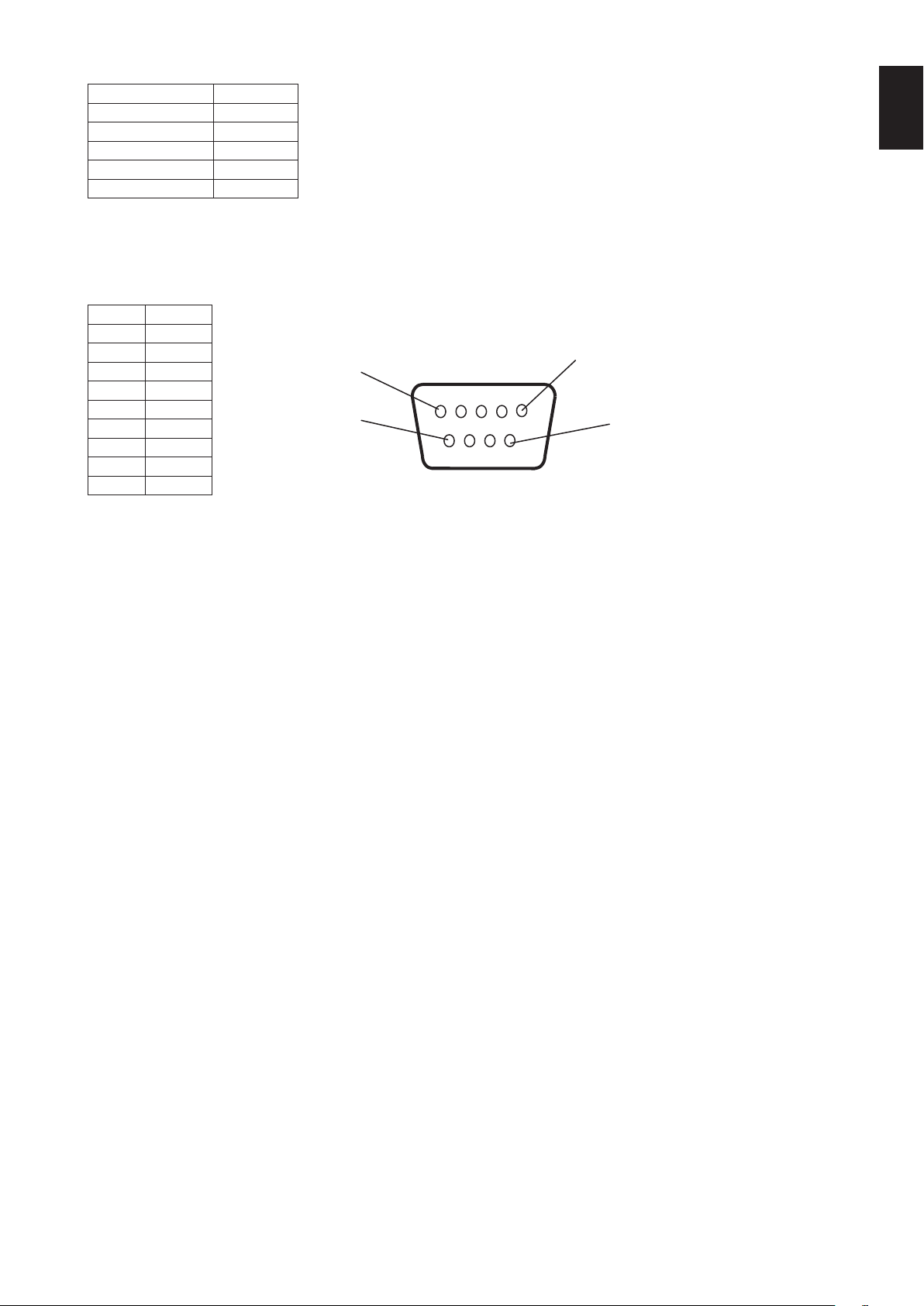
English-49
English
1) Interface
PROTOCOL RS-232C
BAUD RATE 9600 [bps]
DATA LENGTH 8 [bits]
PARITY NONE
STOP BIT 1 [bit]
FLOW CONTROL NONE
This LCD monitor uses RXD, TXD and GND lines for RS-232C control.
The reverse type cable (null modem cable) (not included) should be used for RS-232C control.
2) PIN ASSIGNMENT
RS-232C input/output
1
6
5
9
D-SUB 9P (Monitor side)
Pin No Name
1 NC
2 RXD
3 TXD
4 NC
5 GND
6 NC
7 NC
8 NC
9 NC
This LCD monitor uses RXD, TXD and GND lines for RS-232C control.
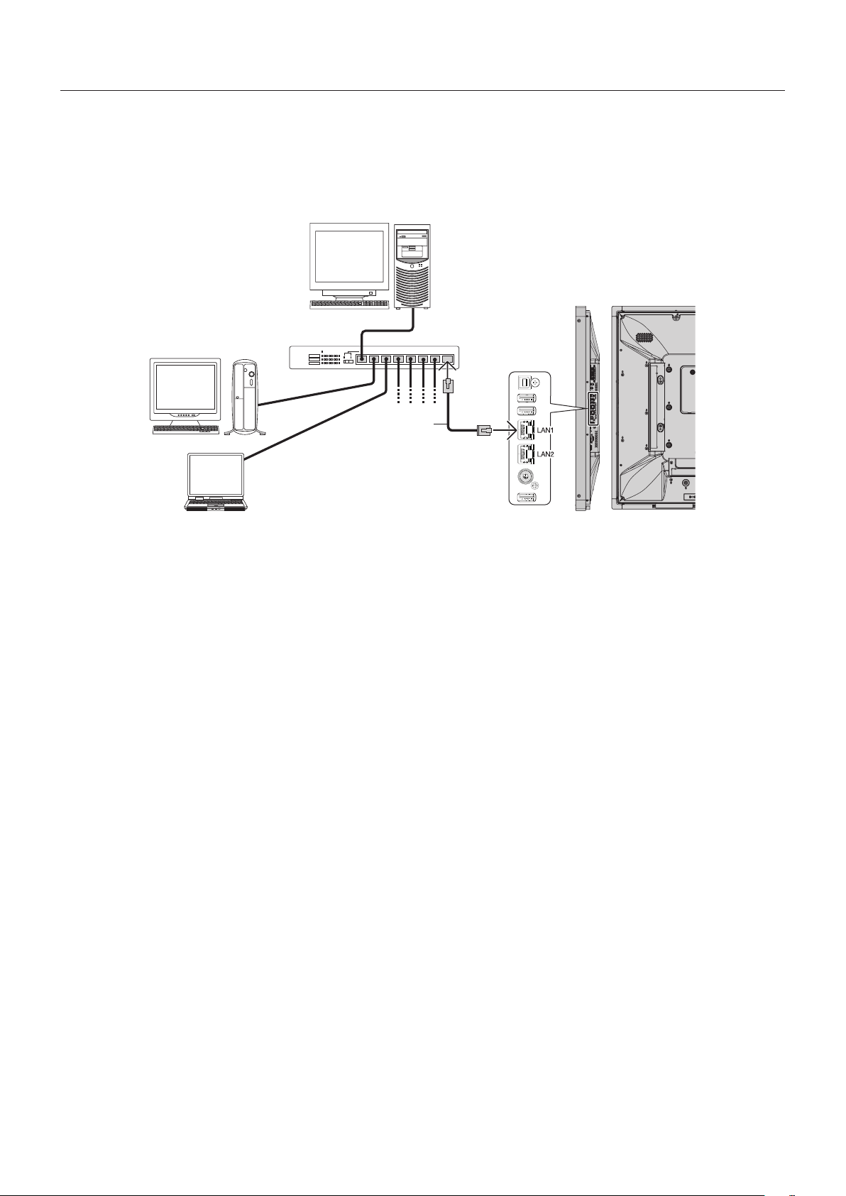
English-50
Connecting to a Network
Using a LAN cable allows you to specify the Network Settings and the Alert Mail Settings by using an HTTP server function.
To use a LAN connection, you are required to assign an IP address.
Example of LAN connection:
Server
Hub
NOTE: Use a category 5 or higher LAN cable.
LAN cable
(not supplied)
Network Setting by Using an HTTP Browser
Overview
Connecting the monitor to a network allows for monitor control from a computer via the network.
The IP address and subnet mask of the monitor can be set on the Network Setting screen of the web browser by using an HTTP
server. Please be sure to use “Microsoft Internet Explorer 10” or a higher version for the web browser.
(This device uses “JavaScript” and “Cookies” and the browser should be set to accept these functions. The setting method will
vary depending on the version of the browser. Please refer to the help files and the other information provided in your software.)
Access is gained to the HTTP server function by starting the Web browser on the computer via the network connected to the
monitor and entering the following URL as described below:
Network Setting
http://<the Monitor’s IP address>/index.html
HINT: The default IP address is assigned automatically to the monitor.
The exclusive application can be downloaded from our website.
NOTE: If the MONITOR NETWORK SETTINGS screen does not appear in the web browser, press the Ctrl+F5 keys to
refresh your web browser (or clear the cache).
If the monitor appears to be slow in response to commands or clicks on buttons in the browser, or the general speed
of operation is unacceptable, this may be due to network traffic or the settings on your network. Should this happen,
consult your network administrator.
The monitor may not respond if the buttons shown on the browser are repeatedly pressed in rapid intervals. Should
this happen, wait a moment and repeat. If you still can’t get a response, turn the monitor off and then back on.
To control a monitor please use the control command. See “Control command diagram” (page 56).
Controlling the LCD monitor via LAN Control

English-51
English
Preparation Before Use
Connect the monitor to the network, using a commercially available LAN cable, before attempting to use browser operations.
Operation with a browser that uses a proxy server may not be possible depending on the type of proxy server and the setting
method. Although the type of proxy server will be a factor, it is possible that items that have been set will not be shown,
depending on the effectiveness of the cache, and the contents set from the browser may not be reflected in operation. It is
recommended that a proxy server is not used unless the network environment requires it.
Handling of the Address for Operation via a Browser
A host name can be used in the following cases (corresponding to the IP address of the monitor):
The host name must be registered in the domain name server (DNS) by the network administrator. You can then access the
network settings of the monitor via this registered host name by using a compatible browser.
If the host name has been configured in the “HOSTS” file of the computer being used, you can then access the network settings
of the monitor via this host name by using a compatible browser.
Example 1: When the host name of the monitor has been set to “pd.nec.co.jp”, access is gained to the network setting by
specifying http://pd.nec.co.jp/index.html for the address or the entry column of the URL.
Example 2: When the IP address of the monitor is “192.168.73.1”, access is gained to the mail alert settings by specifying
http://192.168.73.1/index.html for the address or the entry column of the URL.
Operation
Access the following address to show HOME.
http://<the Monitor’s IP address>/index.html
Click each link on the left column below HOME.
REMOTE CONTROL
Enable an operation to control the monitor equivalent to the keys on the remote control.
OSD menu
Enable the operation to set the following OSD menu:
INPUT, PICTURE, AUDIO, SCHEDULE, MULTI INPUT, OSD, MULTI DISPLAY, DISPLAY PROTECTION, CONTROL, OPTION,
SYSTEM.
NOTE: Function of buttons which are shown on setting pages.
[APPLY]: Save your settings.
[CANCEL]: Return to the previous settings. NOTE: CANCEL is disabled after clicking APPLY.
[RELOAD]: Reload the settings.
[RESET]: Resets to the initial setting.
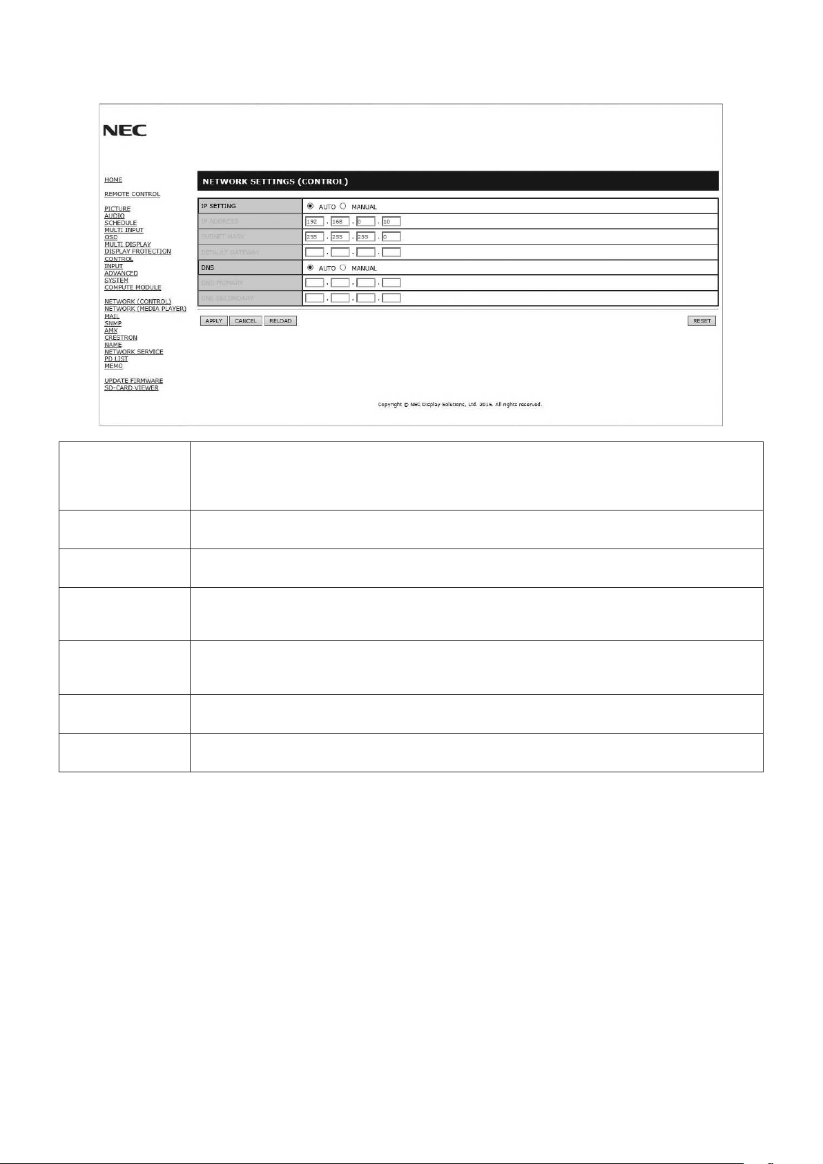
English-52
Network Setting
Click on “NETWORK” on the left column below HOME.
IP SETTING Select an option for setting the IP ADDRESS.
AUTO: Automatically assign an IP address.
MANUAL: Manually set an IP address for the monitor connected to the network.
NOTE: Consult your network administrator if you have any trouble.
IP ADDRESS Set your IP address for the monitor connected to the network when [MANUAL] is selected for
[IP SETTING].
SUBNET MASK Set your subnet mask data for the monitor connected to the network when [MANUAL] is selected for
[IP SETTING].
DEFAULT GATEWAY Set your default gateway for the monitor connected to the network when [MANUAL] is selected for
[IP SETTING].
NOTE: Set as [0.0.0.0] to delete the setting.
DNS Set for IP ADDRESS setting of DNS server.
AUTO: The DNS server connected to the monitor will automatically assign its IP address.
MANUAL: Manually enter the IP address of the DNS server that is connected with the monitor.
PRIMARY DNS Enter the primary DNS server settings of the network connected with the monitor.
NOTE: Enter [0.0.0.0] to delete the setting.
SECONDARY DNS Enter the secondary DNS server settings of the network connected with the monitor.
NOTE: Enter [0.0.0.0] to delete the setting.
NOTE: The following settings will be set back to the factory settings when IP ADDRESS RESET is selected at CONTROL of
the OSD:
[IP SETTING]: AUTO, [IP ADDRESS]: 192.168.0.10, [SUBNET MASK]: 255.255.255.0, [DNS]: AUTO [DEFAULT
GATEWAY], [PRIMARY DNS] and [SECONDARY DNS] are blank.
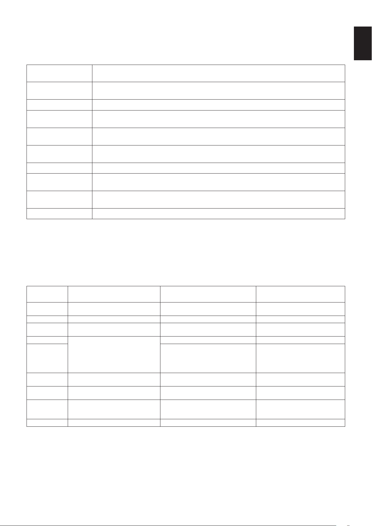
English-53
English
Mail Setting
Click on “MAIL” on the left column below HOME.
This option notifies your computer about an error message via e-mail when using wired LAN. An error message will be sent
when an error occurs in the monitor.
ALERT MAIL Selecting [ENABLE] will turn on the Alert Mail feature.
Selecting [DISABLE] will turn off the Alert Mail feature.
STATUS MESSAGE Selecting [ENABLE] will turn on the STATUS MESSAGE feature.
Selecting [DISABLE] will turn off the STATUS MESSAGE feature.
SENDER’S ADDRESS Type in the sender’s address. Up to 60 alphanumeric and symbols characters can be used.
SMTP SERVER Type in the SMTP server name to be connected with the monitor.
Up to 60 alphanumeric characters can be used.
RECIPIENT’S
ADDRESS 1 TO 3
Type in your recipient’s address. Up to 60 alphanumeric and symbols characters can be used.
AUTHENTICATION
METHOD
This selects the authentication method of the email transmission.
POP3 SERVER This specifies the address of the POP3 server that is used in the authentication of the email.
USER NAME This sets the user name for logging into the authentication server when authentication is required
for the email transmission. Up to 60 alphanumeric characters can be used.
PASSWORD This sets the password for logging into the authentication server when authentication is required for
the email transmission. Up to 60 alphanumeric characters can be used.
TEST MAIL Click on this button to send a test email to check if your settings are correct.
NOTE: •Ifyouexecuteatest,youmaynotreceiveanAlertemail.
Should this happen, check whether the network settings are correct.
•Ifyouenteredanincorrectaddressinatest,youmaynotreceiveanAlertemail.
Should this happen, check that the Recipient’s Address is correct.
HINT: For the control command diagram, please see the file “External_Control.pdf” on the CD-ROM supplied with this
monitor.
Alert error message list
Error number
* ErrorCode
Alert mail Message Explanation Measure
70h ~ 7Fh
The monitor’s power supply is not
functioning normally.
Standby power abnormal Please contact your supplier.
80h ~ Fh The cooling fan has stopped. Cooling fan abnormal Please contact your supplier.
90h ~ 9Fh
The monitor’s backlight unit is not
functioning normally.
Backlight abnormal Please contact your supplier.
A0h ~ AFh The monitor is overheated. Temperature abnormal Please contact your supplier.
A2h
A Sensor reached the temperature limit
which was specified in the OSD.
*Condition: DISPLAY PROTECTION-FAN
CONTROL-COOLING FAN = AUTO
Reconfirm the settings in the OSD
(DISPLAY PROTECTION-FAN
CONTROL) or please contact your
supplier.
B0h ~ BFh
The monitor does not receive an input
signal.
No signal Please check “No picture” in
“Troubleshooting”.
D0h
The remaining capacity of the error log
decreased.
The Proof of Play log memory size is
1 more hour.
Please get a log by using PD external
command. See page 55.
D1h
The battery for clocks is empty. The battery is empty. Please connect the monitor to the
power then recharge the battery.
Please set (DATE & TIME) in OSD.
E0h ~ EFh A system error occurred in the monitor. System error. Please contact your supplier.
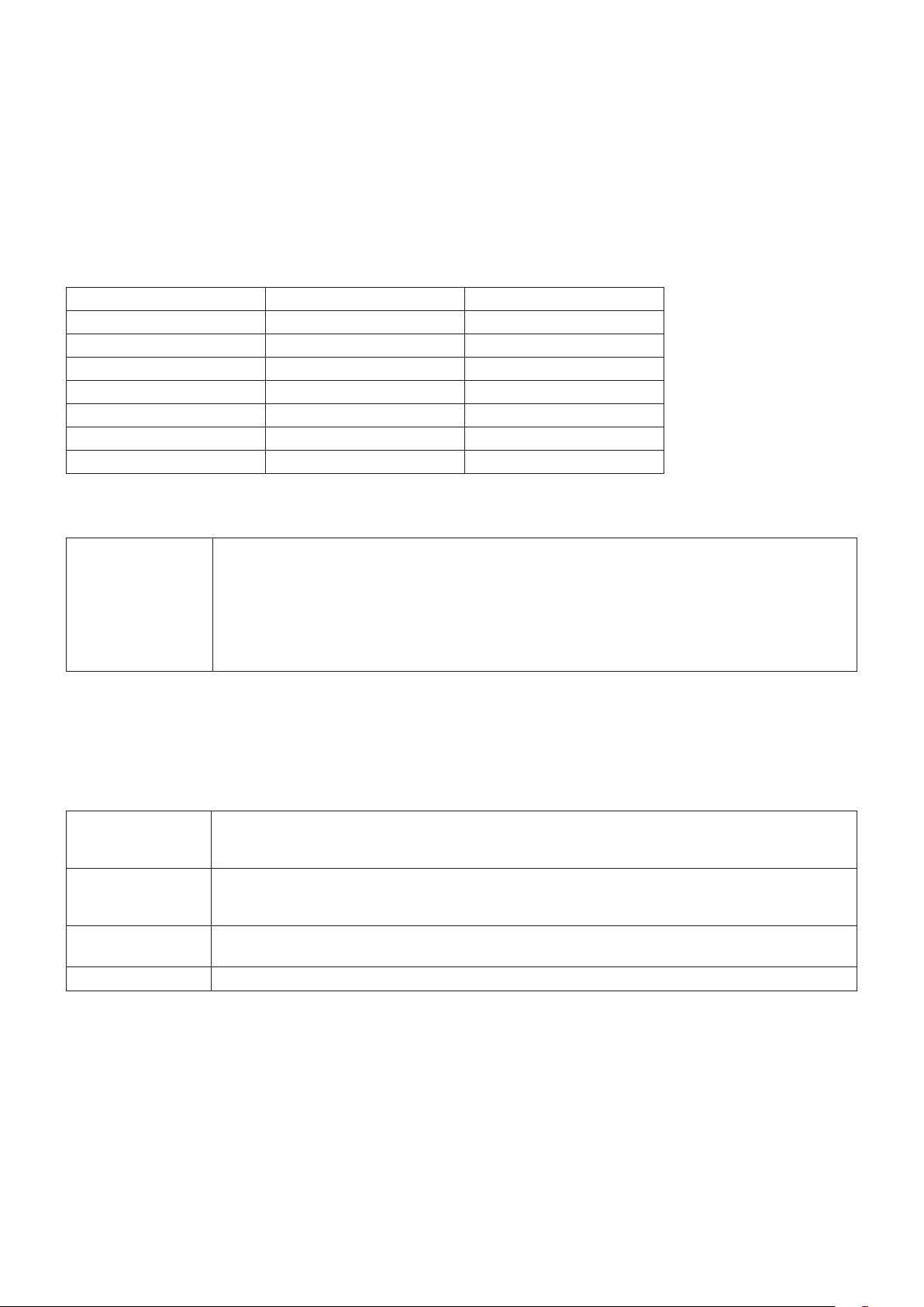
English-54
SNMP Settings
Click on “SNMP” on the left column below HOME.
The SNMP protocol is used to get status information and to control a monitor directly via the network.
Version:
SNMP v1 Authenticated plaintext by community name, does not return a confirmation message of the trap.
SNMP v2c Authenticated plaintext by community name, returns a confirmation message of the trap.
Community name:
The default setting of community name is “public”. It is read only. You can set community names for up to 3 settings.
Trap:
Sending error message to a specified address when an error occurs in the monitor.
Check Box Explanation Error code
Temperature Temperature abnormal 0xA0, 0xA1, 0xA2
Fan Cooling fan abnormal 0x80, 0x81
Power Power abnormal 0x70, 0x71, 0x72, 0x78
Inverter/Backlight Inverter or backlight abnormal 0x90, 0x91
No Signal No signal 0xB0
PROOF OF PLAY Lower the log storage 0xD0
System Error System error 0xE0
AMX Settings
Click on “AMX” on the left column below HOME.
AMX BEACON To turn on or off for the detection from AMX Device Discovery when connecting to a network
supported by an AMX’s NetLinx control system.
HINT:
When using a device that supports AMX Device Discovery, all AMX NetLinx control systems will
recognize the device and download the appropriate Device Discovery Module from an AMX server.
Selecting [ENABLE] AMX Device Discovery will detect the device.
Selecting [DISABLE] AMX Device Discovery will not detect the device.
CRESTRON Settings
Click on “CRESTRON” on the left column below HOME.
CRESTRON ROOMVIEW compatibility
The monitor supports CRESTRON ROOMVIEW, allowing multiple devices connected in the network to be managed and
controlled from a computer or a controller.
For further information, visit http://www.crestron.com
ROOMVIEW ROOMVIEW for managing from the computer.
ON: Enables ROOMVIEW.
OFF: Disables ROOMVIEW.
CRESTRON
CONTROL
CRESTRON CONTROL for managing from the controller.
ON: Enables CRESTRON CONTROL.
OFF: Disables CRESTRON CONTROL.
CONTROLLER IP
ADDRESS
Sets the IP address of the CRESTRON SERVER.
IP ID Sets your CRESTRON SERVER IP ID.
HINT: The CRESTRON settings are required only for use with CRESTRON ROOMVIEW.
For further information, visit http://www.crestron.com
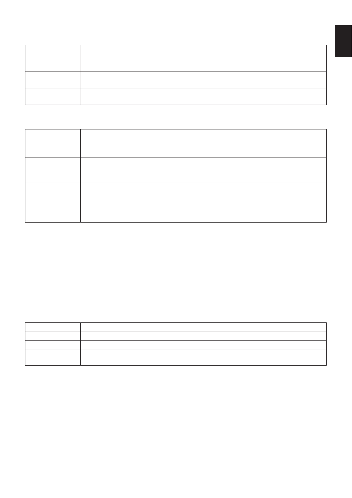
English-55
English
Name Settings
Click on “NAME” on the left column below HOME.
MONITOR NAME Defines a monitor name. The name must be max. 16 characters long. The default is the model name.
HOST NAME
(CONTROL)
Type in the hostname of the monitor which is connected to the network.
Up to 15 alphanumeric characters can be used.
HOST NAME (MP) Type in the hostname of the network to be used in the Media Player connected to the monitor.
Up to 15 alphanumeric characters can be used.
DOMAIN NAME Type in the domain name of the network which is connected with the monitor.
Up to 60 alphanumeric characters can be used.
Network SERVICE Settings
Click on “NETWORK SERVICE” on the left column below HOME.
PJLink CLASS Set a class for PJLink*.
NOTE: PJLink is a network interface standard that JBMIA established.
http://pjlink.jbmia.or.jp/index.html
This monitor is available for class1 and class2 command.
NOTIFY FUNCTION
ENABLE
Enable or disable a notification of the monitor network condition. This function is only for class2.
NOTIFY ADDRESS Set an IP ADDRESS to which the monitor network status will be sent. This function is only for class2.
PJLink PASSWORD Set a password for PJLink*. The password must be max. 32 characters long. Do not forget your
password. If you forget your password, consult your supplier.
HTTP PASSWORD Set a password for the HTTP server. The password must be max. 10 characters long.
HTTP PASSWORD
ENABLE
An HTTP PASSWORD is required when logging into the HTTP server.
Set the monitor name as the USER NAME when entering the password.
*What is PJLink?
PJLink is a standardization of protocol used for controlling devices of different manufacturers. This standard protocol was
established by Japan Business Machine and Information System Industries Association (JBMIA) in 2005.
The device supports all commands of PJLink.
PD LIST Information
Click on “PD LIST” on the left column below HOME.
Shows a list of monitor IDs and IP addresses of multiple monitors which are daisy-chained.
NOTE: Only the master monitor can show the list.
MEMO Settings
Click on “MEMO” on the left column below HOME.
Set a title and message.
TITLE The title must be max. 24 characters long.
MESSAGE A message must be max. 240 characters long.
MEMO PASSWORD The default is “0000”.
MEMO PASSWORD
ENABLE
A MEMO PASSWORD is required when selecting MEMO PASSWORD ENABLE.
SD-CARD VIEWER setting
Click “SD-CARD VIEWER” on the left side of HOME.
Please refer to Using SHARED SD card SETTINGS (See page 26).
External Control
Connecting external device
There are two ways to connect an external device to the monitor.
•RS-232C terminal.
Connecting an external device to the RS-232C terminal of the monitor with a RS-232C cable.
•LAN port.
Connecting an external device to the LAN port of the monitor with a LAN cable.
For further information regarding the type of LAN cable to use, please consult your network administrator.
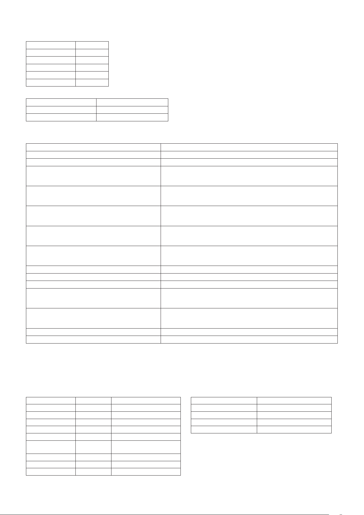
English-56
Connecting interface
RS-232C Interface
PROTOCOL RS-232C
BAUD RATE 9600 [bps]
DATA LENGTH 8 [bits]
PARITY NONE
STOP BIT 1 [bit]
FLOW CONTROL NONE
LAN interface
PROTOCOL TCP
PORT NUMBER 7142
COMMUNICATION SPEED AUTO setting (10/100Mbps)
Control command diagram
For other commands, please see “External_Control.pdf” file on the CD-ROM supplied with the monitor.
Function (Monitor ID = 1) Code Data
Power ON 01 30 41 30 41 30 43 02 43 32 30 33 44 36 30 30 30 31 03 73 0d
Power OFF 01 30 41 30 41 30 43 02 43 32 30 33 44 36 30 30 30 34 03 76 0d
Input Source Select DisplayPort1
01 30 41 30 45 30 41 02 30 30 36 30 30 30 30 46 03 04 0d
or
01 30 41 30 45 30 41 02 31 31 30 36 30 30 30 46 03 04 0d
Input Source Select DisplayPort2
01 30 41 30 45 30 41 02 30 30 36 30 30 30 31 30 03 73 0d
or
01 30 41 30 45 30 41 02 31 31 30 36 30 30 31 30 03 73 0d
Input Source Select DVI
01 30 41 30 45 30 41 02 30 30 36 30 30 30 30 33 03 71 0d
or
01 30 41 30 45 30 41 02 31 31 30 36 30 30 30 33 03 71 0d
Input Source Select HDMI1
01 30 41 30 45 30 41 02 30 30 36 30 30 30 31 31 03 72 0d
or
01 30 41 30 45 30 41 02 31 31 30 36 30 30 31 31 03 72 0d
Input Source Select HDMI2
01 30 41 30 45 30 41 02 30 30 36 30 30 30 31 32 03 71 0d
or
01 30 41 30 45 30 41 02 31 31 30 36 30 30 31 32 03 71 0d
Input Source Select VGA (RGB) 01 30 41 30 45 30 41 02 30 30 36 30 30 30 30 31 03 73 0d
Input Source Select VGA (YPbPr) 01 30 41 30 45 30 41 02 30 30 36 30 30 30 30 43 03 01 0d
Input Source Select VIDEO 01 30 41 30 45 30 41 02 30 30 36 30 30 30 30 35 03 77 0d
Input Source Select MP
01 30 41 30 45 30 41 02 30 30 36 30 30 30 38 37 03 7D 0d
or
01 30 41 30 45 30 41 02 31 31 30 36 30 30 38 37 03 7D 0d
Input Source Select OPTION
01 30 41 30 45 30 41 02 30 30 36 30 30 30 30 44 03 06 0d
or
01 30 41 30 45 30 41 02 31 31 30 36 30 30 30 44 03 06 0d
Sound Mute ON 01 30 41 30 45 30 41 02 30 30 38 44 30 30 30 31 03 09 0d
Sound Mute OFF 01 30 41 30 45 30 41 02 30 30 38 44 30 30 30 32 03 0a 0d
ASCII Control command
This monitor supports control command, which is listed in the “External_Control.pdf” file on the CD-ROM supplied with the
monitor, but also supports common ASCII control command, which is used for controlling the NEC monitor or projector from a
connected PC. For further information please visit our website.
Parameter
Input command Status command
Input signal name Response Parameter Response Error status
DVI dvi dvi or dvi1 error:temp Temperature abnormal
HDMI1 hdmi1 hdmi1 or hdmi error:fan Cooling fan abnormal
HDMI2 hdmi2 hdmi2 error:light Inverter or backlight abnormal
DisplayPort1 DisplayPort1 DisplayPort1 or DisplayPort error:system System error
DisplayPort2 DisplayPort2 DisplayPort2
VGA vga vga, vga1, computer,
computer1, rgb or rgb1
VIDEO video video or video1
MP mp mp
OPTION option option
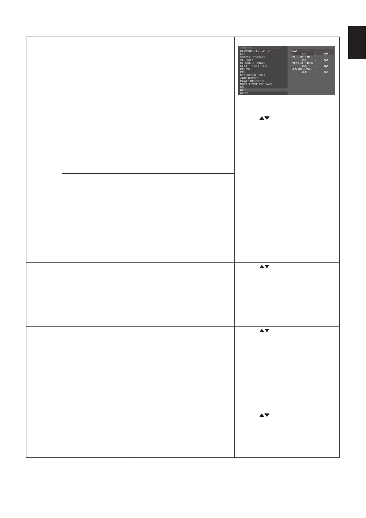
English-57
English
Supporting HDMI CEC command
OSD menu
HDMI CEC command name Explanation
Setting
CEC
(Consumer
Electronics
Control)
One Touch Play If HDMI CEC supporting devices are
turned on, the monitor connected to the
devices by HDMI cable is also turned
on automatically. After that, the input
switches to HDMI from an input, which
you selected.
If the monitor is turned on when HDMI
CEC devices are turned on, it changes
the input from the original one to HDMI.
To set CEC menus please follow the steps
below.
By using buttons select CONTROL >
CEC then press SET/POINT ZOOM button
on the CEC.
By using + - buttons select ON then press
SET/POINT ZOOM button on the ON.
Remote Control Pass
Through
The monitor’s wireless remote control
button operation is functioning to HDMI
CEC supporting devices.
For example, if turning on the monitor
by wireless remote control and pressing
the play button, HDMI CEC supporting
devices will also be turned on and play.
Power Status Connected HDMI CEC supporting
devices obtains the monitor’s power
status, such as the monitor is in standby
mode or on.
System Information This function obtains the information of a
connected HDMI CEC supported device
(CEC version, Physical Address). In
addition, this function copes with “Change
Language function”.
If the language for the monitor is
changed, the language for a connected
HDMI CEC supported device is changed
to the same language, which is selected
for the monitor.
For the “Change Language function”, it is
necessary that the connected HDMI CEC
supported device be able to cope with
multi-language.
AUTO
TURN OFF
System Standby If the monitor is set to standby using the
wireless remote control supplied with the
monitor, HDMI CEC supported devices
also go into standby at the same time.
If the monitor goes into standby while
an HDMI CEC supported device is
recording, the device is kept on. Please
refer to the user’s manual supplied with
the HDMI CEC supported device for
further information.
By using
buttons select AUTO TURN
OFF then press SET/POINT ZOOM.
By using + - buttons select YES then press
SET/POINT ZOOM button on the YES.
AUDIO
RECEIVER
System Audio Control The function sends digital audio signal
through the HDMI cable. Please set an
HDMI CEC audio amplifier between the
monitor and an HDMI CEC supported
device with an HDMI cable.
The Volume button on the wireless
remote control supplied with the
monitor is also controlling the volume
of the connected HDMI CEC audio
amplifier.
While this function is active, the internal
speaker or external speaker connected to
the monitor is set to MUTE automatically.
By using buttons select AUDIO
RECIEVER then press SET/POINT
ZOOM.
By using + - buttons select YES then press
SET/POINT ZOOM button on the YES.
SEARCH
DEVICE
Device OSD Name Transfer This function obtains the connected
HDMI CEC supported device’s name.
By using
buttons select SEARCH
DEVICE then press SET/POINT ZOOM.
By using + - buttons select YES then press
SET/POINT ZOOM button on the YES.
Routing Control By selecting a device name, the HDMI
CEC supported device input switches to
the input you selected. After selecting the
device, wireless remote control operation
is functioning for the selected device.
This CEC function is supporting Feature Abort. We recommend that connecting this monitor to a device supporting HDMI CEC.
Please refer to Connections (See page 16) for HDMI CEC devices connection.

English-58
Using the “SET/POINT ZOOM” button on the remote control enlarges part of the screen image.
Press the CH+/- button to zoom in or out. The image can be expanded up to 10 times.
1 Press the [SET/POINT ZOOM] button on the remote control. The icon looks like a magnifier.
2 Move the magnifier icon with the [ ] [ ] [+] [-] buttons.
3 Press the [CH+] to zoom in. Press [CH-] to zoom out.
4 Press the [SET/POINT ZOOM] to let the icon disappear.
5 Press the [EXIT] to return to the normal image size.
6 Press the [MENU] to open the OSD menu.
NOTE: •Whenusing this function, the image may look distorted.
•Thisfunctionis not available when set to IMAGE FLIP (except for NONE), MULTI PICTURE MODE, SCREEN
SAVER, SUPER in INPUT CHANGE, CLOSED CAPTION, TILE MATRIX and TEXT TICKER.
•WhenDYNAMIC or ZOOM is selected in ASPECT, the image will change to FULL. Then start with POINT ZOOM.
After exiting POINT ZOOM, ASPECT will return to the previous ASPECT settings. When ASPECT is changed
during the POINT ZOOM operation, DYNAMIC and ZOOM will be set to FULL image.
•Themagniericondoesnotmovetoanoimagearea.
•POINTZOOMreturnstothenormalimagesizeafterchangingtheinputsignalorwhenthemonitorispoweredoff.
•POINTZOOMwill become inactive when changing the ASPECT setting during the POINT ZOOM operation.
•When the POINT ZOOM is active, the STILL function is not available.
•POINTZOOMisnotavailablewitha3840x2160(60Hz)signal.
POINT ZOOM

English-59
English
PROOF OF PLAY
This function allows to send messages for the current status of the monitor by self-diagnosis.
Check item Message
①
INPUT DVI, DisplayPort1, DisplayPort2, HDMI1, HDMI2, OPTION*, MP, VGA (RGB/YPbPr), VIDEO
②
Resolution ex. (H)1920, (V)1080 , (H)1360, (V)768 or No signal or Invalid signal
③
AUDIO INPUT IN1, IN2, DisplayPort1, DisplayPort2, HDMI1, HDMI2, OPTION*, MP
④
Audio signal Audio in or No Audio in or N/A (IN1, IN2, OPTION (analog)*)
⑤
Picture Image Normal Picture or No Picture
⑥
AUDIO OUT Normal Audio or No Audio
⑦
TIME (year)/(month)/(day)/(hour)/(minutes)/(second)
h
EXPANSION DATA
00h: Normal Proof of Play event
01h: Proof of Play event is “last power on time”
10h: MEDIA PLAYER is stop
11h: MEDIA PLAYER is start
12h: MEDIA PLAYER is pause
13h: MEDIA PLAYER error occur
20h: Contents Copy from USB
21h: Contents Copy form network folder
30h: Contents Copy Success
31h: Contents Copy Error (No media)
32h: Contents Copy Error (Connect error)
33h: Contents Copy Error (Out of disk space)
34h: Contents Copy Error (Read/Write error)
40h: Human detected (Human sensor Status)
41h: Human detect cleared (Human Sensor Status)
*: This function depends on which option board you are using.
Example:
①
HDMI1
②
1920 x 1080
③
HDMI1
④
IN1
⑤
Normal Picture
⑥
Normal Audio
⑦
2014/1/1/0h/0m/0s
h
10h: MEDIA PLAYER is stop
NOTE: For the Proof of Play function, please see the “External_Control.pdf” on the CD-ROM supplied with this monitor.
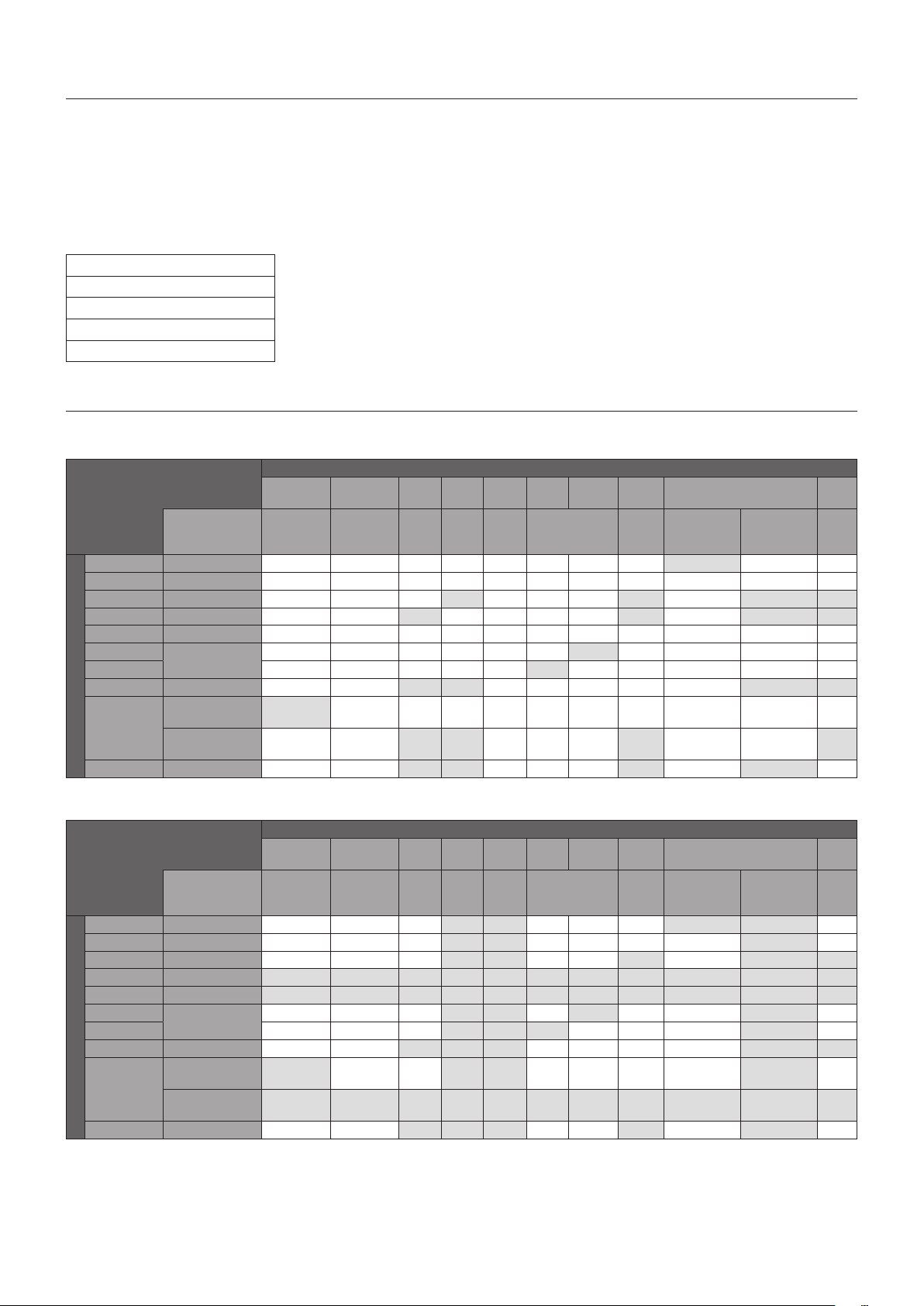
English-60
This function allows to get the monitor status via wireless communication, even while the monitor’s main power is off or is not
yet installed.
Even some OSD items may be set by using this feature.
NOTE: Sensor position: See page 9 and page 10.
Please contact your supplier for detailed information.
Complied with ISO 15693.
Function name
Setting Copy
Setting read and write function
Display information
Security Setting
PIP (Picture in Picture) matrix
a DisplayPort = 1.1a/HDMI = MODE1
Sub picture
DisplayPort1 DisplayPort2 DVI HDMI1 HDMI2
VGA
(RGB)
VGA
(YPbPr)
Video OPTION MP
Connector
DisplayPort
IN1
DisplayPort
IN2
DVI-D
HDMI
IN1
HDMI
IN2
VGA (RGB,
YPbPr)
VIDEO
IN
Option board
slot (SLOT2
(DP))
Option board
slot (SLOT2
(HDMI))
-
Main picture
DisplayPort1 DisplayPort IN1 Yes Yes Yes Yes Yes Yes Yes Yes No Yes Yes
DisplayPort2 DisplayPort IN2 Yes Yes Yes Yes Yes Yes Yes Yes Yes Yes Yes
DVI DVI-D Yes Yes Yes No Yes Yes Yes No Yes No No
HDMI1 HDMI IN1 Yes Yes No Yes Yes Yes Yes No Yes No No
HDMI2 HDMI IN2 Yes Yes Yes Yes Yes Yes Yes Yes Yes Yes Yes
VGA (RGB)
VGA (RGB,
YPbPr)
Yes Yes Yes Yes Yes Yes No Yes Yes Yes Yes
VGA (YPbPr) Yes Yes Yes Yes Yes No Yes Yes Yes Yes Yes
VIDEO VIDEO IN Yes Yes No No Yes Yes Yes Yes Yes No No
OPTION
Option board slot
(SLOT2 (DP))
No Yes Yes Yes Yes Yes Yes Yes Yes Yes Yes
Option board slot
(SLOT2 (HDMI))
Yes Yes No No Yes Yes Yes No Yes Yes No
MP - Yes Yes No No Yes Yes Yes No Yes No Yes
b DisplayPort = 1.1a/HDMI = MODE2
Sub picture
DisplayPort1 DisplayPort2 DVI HDMI1 HDMI2
VGA
(RGB)
VGA
(YPbPr)
Video OPTION MP
Connector
DisplayPort
IN1
DisplayPort
IN2
DVI-D
HDMI
IN1
HDMI
IN2
VGA (RGB,
YPbPr)
VIDEO
IN
Option board
slot (SLOT2
(DP))
Option board
slot (SLOT2
(HDMI))
-
Main picture
DisplayPort1 DisplayPort IN1 Yes Yes Yes No No Yes Yes Yes No No Yes
DisplayPort2 DisplayPort IN2 Yes Yes Yes No No Yes Yes Yes Yes No Yes
DVI DVI-D Yes Yes Yes No No Yes Yes No Yes No No
HDMI1 HDMI IN1 No No No No No No No No No No No
HDMI2 HDMI IN2 No No No No No No No No No No No
VGA (RGB)
VGA (RGB,
YPbPr)
Yes Yes Yes No No Yes No Yes Yes No Yes
VGA (YPbPr) Yes Yes Yes No No No Yes Yes Yes No Yes
VIDEO VIDEO IN Yes Yes No No No Yes Yes Yes Yes No No
OPTION
Option board slot
(SLOT2 (DP))
No Yes Yes No No Yes Yes Yes Yes No Yes
Option board slot
(SLOT2 (HDMI))
No No No No No No No No No No No
MP - Yes Yes No No No Yes Yes No Yes No Yes
INTELLIGENT WIRELESS DATA
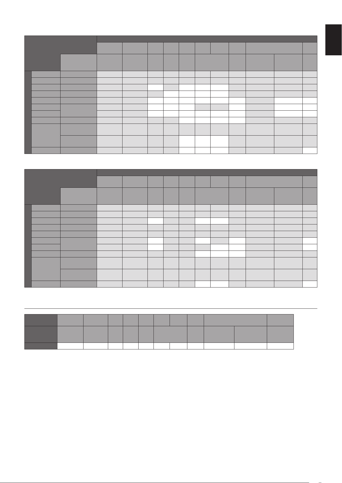
English-61
English
c DisplayPort = 1.2/HDMI = MODE1
Sub picture
DisplayPort1 DisplayPort2 DVI HDMI1 HDMI2
VGA
(RGB)
VGA
(YPbPr)
Video OPTION MP
Connector
DisplayPort
IN1
DisplayPort
IN2
DVI-D
HDMI
IN1
HDMI
IN2
VGA (RGB,
YPbPr)
VIDEO
IN
Option board
slot (SLOT2
(DP))
Option board
slot (SLOT2
(HDMI))
-
Main picture
DisplayPort1 DisplayPort IN1 No No No No No No No No No No No
DisplayPort2 DisplayPort IN2 No No No No No No No No No No No
DVI DVI-D No No Yes No Yes Yes Yes No No No No
HDMI1 HDMI IN1 No No No Yes Yes Yes Yes No No No No
HDMI2 HDMI IN2 No No Yes Yes Yes Yes Yes Yes No Yes Yes
VGA (RGB)
VGA (RGB,
YPbPr)
No No Yes Yes Yes No No Yes No Yes Yes
VGA (YPbPr) No No Yes Yes Yes Yes Yes Yes No Yes Yes
VIDEO VIDEO IN No No No No Yes Yes Yes Yes No No No
OPTION
Option board slot
(SLOT2 (DP))
No No No No No No No No No No No
Option board slot
(SLOT2 (HDMI))
No No No No Yes Yes Yes No No No No
MP - No No No No Yes Yes Yes No No No Yes
d DisplayPort = 1.2/HDMI = MODE2
Sub picture
DisplayPort1 DisplayPort2 DVI HDMI1 HDMI2
VGA
(RGB)
VGA
(YPbPr)
Video OPTION MP
Connector
DisplayPort
IN1
DisplayPort
IN2
DVI-D
HDMI
IN1
HDMI
IN2
VGA (RGB,
YPbPr)
VIDEO
IN
Option board
slot (SLOT2
(DP))
Option board
slot (SLOT2
(HDMI))
-
Main picture
DisplayPort1 DisplayPort IN1 No No No No No No No No No No No
DisplayPort2 DisplayPort IN2 No No No No No No No No No No No
DVI DVI-D No No Yes No No Yes Yes No No No No
HDMI1 HDMI IN1 No No No No No No No No No No No
HDMI2 HDMI IN2 No No No No No No No No No No No
VGA (RGB)
VGA (RGB,
YPbPr)
No No Yes No No Yes No Yes No No Yes
VGA (YPbPr) No No Yes No No No Yes Yes No No Yes
VIDEO VIDEO IN No No No No No Yes Yes Yes No No No
OPTION
Option board slot
(SLOT2 (DP))
No No No No No No No No No No No
Option board slot
(SLOT2 (HDMI))
No No No No No No No No No No No
MP - No No No No No Yes Yes No No No Yes
Video out
Main picture
DisplayPort1 DisplayPort2 DVI HDMI1 HDMI2
VGA
(RGB)
VGA
(YPbPr)
Video OPTION MP
Connector
DisplayPort
IN1
DisplayPort
IN2
DVI-D
HDMI
IN1
HDMI
IN2
VGA (RGB,
YPbPr)
VIDEO
IN
Option board
slot (SLOT2
(DP))
Option board
slot (SLOT2
(HDMI))
-
DisplayPort Yes No No No No No No No Yes No No
When the monitor output a signal from the DisplayPort out, Please select input signal DisplayPort1 or OPTION.
This monitor’s signal output function is supporting contents which is protected by HDCP. In this case, up to 3 monitors are connectable.
When using an option, Please set SLOT2 CH SETTING to 1CH then set SLOT2 CH SELECT to DisplayPort (See page 44).
NOTE: To output a signal from the DisplayPort out, some Slot2 type options are only available which have DisplayPort signal out.

English-62
Reduced Footprint: Provides the ideal solution for environments with superior image quality.
SPECTRAVIEW ENGINE: This system is designed for improvement the visual quality of the monitor.
Each monitor is calibrated at the factory. By making automatic adjustments during operation of the monitor hardware in real
time, optimal settings are configured without any user interaction.
Natural Color Matrix: Combines Six-axis color control and the sRGB standard. Six-axis color control permits color adjustments
via six axes (R, G, B, C, M and Y) rather than through the three axes (R, G and B) previously available. The sRGB standard
provides the monitor with a uniform color profile. This ensures that the colors displayed on the monitor are exactly the same as
on the color printout (with sRGB supporting operating system and sRGB printer). This allows you to adjust the colors on your
screen and customise the color accuracy of your monitor to a variety of standards.
sRGB Color Control: A color management standard which allows for color matching on computer monitors and other
peripherals. The sRGB standard, which is based on a calibrated color space, allows for optimal color representation and
backward compatibility with other common color standards.
OSD (On-Screen-Display) Controls: Allows you to quickly and easily adjust all elements of your screen image via easy to use
on-screen menus.
Plug and Play: The Microsoft
®
solution with the Windows
®
operating system facilitates setup and installation by allowing
the monitor to send its capabilities (such as screen size and resolutions supported) directly to your computer, automatically
optimizing display performance.
IPM (Intelligent Power Manager) System: Provides innovative power-saving methods that allow the monitor to shift to a
lower power consumption level when on but not in use, saving two-thirds of your monitor energy costs, reducing emissions and
lowering the air conditioning costs of the workplace.
FullScan Capability: Allows you to use the entire screen area in most resolutions, significantly expanding image size.
VESA Standard (FDMIv1) Mounting Interface: Allows you to mount the monitor to any VESA standard (FDMIv1) third party
mounting arm or bracket. NEC recommends using mounting equipment which complies with TÜV-GS (Germany) and/or UL1678
standard (North America).
DVI-D: The digital-only subset of the DVI standard ratified by the Digital Display Working Group (DDWG) for digital connections
between computers and monitors. As a digital-only connector, analog support is not provided with a DVI-D connector. As a DVI-
based digital only connection, only a simple adapter is necessary for compatibility between DVI-D and other DVI-based digital
connectors such as DFP and P&D. The DVI interface of this monitor supports HDCP.
ZOOM: Expands/reduces the image size in horizontal and vertical direction.
Self-diagnosis: If an internal error should occur, a failure state will be indicated.
USB hub: Allows the connection of digital cameras, scanners, keyboards and more.
HDCP (High-bandwidth Digital Content Protection): HDCP is a system for preventing illegal copying of video data sent over
a digital signal. If you are unable to view material via the digital input, this does not necessarily mean that the monitor is not
functioning properly. With the implementation of HDCP, there may be cases in which certain content is protected by HDCP and
might not be displayed due to the decision/intention of the HDCP community (Digital Content Protection, LLC).
Option board slot: You can use an option board. Please contact your supplier for detailed information.
DICOM Sim.: A DICOM gamma curve emulation which is stored inside the monitor as fixed Look Up Table values. When
selecting DICOM Sim., these values are loaded into the active Look Up Table of the monitor to create a DICOM like gamma
correction curve. Suitable for DICOM image viewing in clinical review. Must not be used for DICOM image viewing in
diagnostics.
TILE MATRIX, TILE COMP: Shows one image over multiple screens with accuracy while compensating for bezel width.
Features

English-63
English
No picture
•Thesignalcableshouldbecompletelyconnectedtothe
display card/computer.
•Thedisplaycardshouldbecompletelyseatedinitsslot.
•CheckthemainPowerSwitch,itshouldbeintheON
position.
•Power Switches for the monitor and computer should be
in the ON position.
•Makesurethatasupportedresolutionhasbeenselected
on the display card or system being used. If in doubt,
please refer to the user’s manual of the display card or
system to change the resolution.
•Checkthemonitorandyourdisplaycardwithrespectto
compatibility and recommended signal timings.
•Checkthesignalcableconnectorforbentorpushed-in
pins.
•Themonitorautomaticallygoesintostandby at the preset
time period after the video signal was lost. Press the
power on button on the remote control or press the power
button on the monitor.
•ChecktheDVIMODEsettingswhenaDVDplayeror
computer equipment is connected to the DVI input.
•If you unplug the signal cable when starting the computer,
images may not be displayed. Turn off the monitor and
the computer and then connect the signal cable and turn
on the computer and the monitor.
•Check the OPTION POWER setting when you use option
board accessories.
Snowy Picture, Black Screen in DVI input
•ChecktheDVIMODEsettingwhenaDVDplayeror
computer equipment is connected to the DVI input.
Power Button does not respond
•UnplugthepowercordofthemonitorfromtheACoutlet
to turn off and reset the monitor.
•CheckthemainPowerSwitchonthemonitor.
Image persistence
•PleasebeawarethatLCDTechnologymayexperience
a phenomenon known as Image Persistence. Image
Persistence occurs when a residual or “ghost” image of
a previous image remains visible on the screen. Unlike
CRT monitors, the image persistence of LCD monitors is
not permanent, but single still image being displayed for a
long period of time should be avoided. To alleviate image
persistence, put the monitor into standby via remote
control or turn the monitor’s main power off for as long
as the previous image was displayed. For example, if an
image was on the monitor for one hour and a residual
image remains, the monitor should be in standby or main
power off for one hour to erase the image.
NOTE: As with all personal display devices, NEC
DISPLAY SOLUTIONS recommends displaying
moving images, using a moving screen saver, or
changing still images at regular intervals whenever
the screen is idle, or turning it into standby or main
power off of the monitor when not in use.
The image is blinking
•If you use a signal repeater or distributor or a long
cable, this may cause image roughness or blink for a
moment. In this case please connect the cable to the
monitor directly without using a repeater or a distributor,
or replace the cable with a higher quality cable. Using
a twisted pair extender may cause image roughness
depending on the environment where the monitor is in or
the cable you are using. For further information please
ask your supplier.
•Some HDMI cables may not show a correct image.
If input resolution is 1920 x 2160, 3840 x 2160 or
4096 x 2160, please use a HDMI cable which is approved
to support 4K resolution.
The image is unstable, unfocused or swimming is
apparent
•Thesignalcableshouldbecompletelyattachedtothe
computer.
•UsetheOSDImageAdjustcontrolstofocusand
adjust the display by increasing or decreasing the fine
adjustment.
When the display mode is changed, the OSD Image
Adjust settings may need to be re-adjusted.
•Checkthemonitorandyourdisplaycardwithrespectto
compatibility and recommended signal timings.
•Iftextlooksgarbled,changethevideomodetonon-
interlaced and use a 60 Hz refresh rate.
•Theimagemaybedistortedwhenturningthepoweronor
changing the settings.
The image of component signal is greenish
•ChecktoseeiftheVGA (YPbPr) input connector is
selected.
LED on the monitor is not lit (no blue or red color can be
seen)
•ThemainPowerSwitchshouldbeintheONpositionand
the power cord should be connected.
•Makecertainthecomputerisnotinapower-savingmode
(touch the keyboard or move the mouse).
•Check in the OSD that the power indicator option is set to
ON.
LED colors, except for blue, are blinking or glowing
•A certain failure might have occurred, please contact your
supplier.
•If the monitor is powered off by the internal temperature
being higher than the normal operating temperature,
the LED will blink green or amber or red for six times.
Power on the monitor again after confirming the internal
temperature has been reduced to normal operation
temperature.
•The monitor could be in standby.
Press the power on button on the remote control or press
the power button on the monitor.
The image is not properly reproduced
•UsetheOSDImageAdjustcontrolstoincreaseor
decrease the coarse adjustment.
•Makesurethatasupportedresolutionhasbeenselected
on the display card or system being used.
If in doubt, please refer to the user’s manual of the display
card or system to change the resolution.
Troubleshooting

English-64
Either light vertical or horizontal stripes may appear, depending on the specific image pattern. This is not a product fault or degradation.
Selected resolution is not displayed properly
•UseOSDDisplayModetoenterInformationmenuand
confirm that the appropriate resolution has been selected.
If not, select corresponding option.
No Sound
•Checktoseeiftheaudiocableisproperlyconnected.
•ChecktoseeifMUTE is activated. Use the remote control
to enable or disable the Mute function.
•ChecktoseeifVOLUME is set to a minimum.
•Checktoseeifthecomputersupportsanaudiosignal
through DisplayPort.
If unsure, contact your supplier.
•WhenLINEOUTisnotfunctioning,checktoseeif
SURROUND is ON.
•ChecktheInternal/Externalspeakerswitch.
•If HDMI CEC audio device is not connected, please set
“AUDIO RECEIVER” to OFF.
The Remote Control is not functioning
•Check the batteries status of the Remote Control.
•Checkifthebatteriesareinsertedcorrectly.
•CheckiftheRemoteControlispointingatthe remote
control sensor of the monitor.
•Check the status of IR LOCK SETTINGS.
•Theremotecontrolsystemmaynotfunctionwhendirect
sunlight or strong illumination strikes the remote control
sensor of the monitor, or when there is an object in the
path.
•Usersmayexperienceinconsistentremotecontrol
operation if the bottom of the display is within 10 cm from
a structural surface.
The SCHEDULE/OFF TIMER function is not working
properly
•The“SCHEDULE”functionwillbedisabledwhenthe
“OFF TIMER” is set.
•Ifthe“OFFTIMER”functionisenabledandthepowerto
the LCD monitor is turned off when the power supply is
interrupted unexpectedly, then the “OFF TIMER” will be
reset.
Snowy Picture, Poor Sound in TV
•Checkantenna/cableconnection.Usenewcableif
necessary.
The USB Hub does not operate
•ChecktomakesurethattheUSBcableisproperly
connected. Refer to your USB device user’s manual.
•CheckiftheUSBupstreamportonthemonitoris
connected to the USB downstream port on the computer.
Please make sure the computer is ON or USB POWER is
ON.
• Disconnect one upstream USB cable when using
2 upstream connections.
Interference in TV
•Checkcomponentsforshielding,moveawayfrom
monitor if necessary.
USB or RS-232C or LAN control is not available
•CheckRS-232C (reverse type) or the LAN cable.
A category 5 or higher LAN cable is required for
connection.
•Check USB cable connected to USB2 port.
Check the EXTERNAL CONTROL is set to ENABLE then
PC SOURCE is set to EXTERNAL PC.
The monitor goes into standby automatically
•Please check “OFF TIMER” setting.
•Set the “CEC” function to OFF.
Media player function does not recognize the USB
storage device
•Please check a USB storage device is connected to the
USB MP.
• Check the format if this device cannot recognize the
connected USB memory.
• The touch panel function does not support the media
player function. Please use the remote control to set the
media player while the touch panel function is working.
MicroSD card does not work
•Check to make sure the microSD card is properly
connected.
•Check the microSD memory card format.
The touch panel does not respond
•Make sure that PIP (picture in picture), PBP (picture by
picture), TILE MATRIX, ROTATE and ZOOM are not
selected.
•Checktheinputsignalsetting.
•The touch panel function does not support the media
player function. Please use the remote control to set the
media player while the touch panel function is working.
•Make sure that TOUCH POWER setting in USB in
CONTROL is “ON”.
•Check the PC SOURCE setting in USB in CONTROL.
Using slot 2 type PC:
Make sure that PC SOURCE is AUTO or OPTION,
and the input signal is set to OPTION.
Make sure the slot 2 type PC is connected properly.
Using external computer:
Make sure that PC SOURCE is AUTO or EXTERNAL
PC, and the input signal is set to which supplied by the
connected computer.
Make sure the USB cable is connected properly.
•The touch panel function may not work depending on
the specification of an external computer and connecting
method.
•If the TOUCH POWER setting in USB in CONTROL is set
to “ON”, change it to “OFF” and back to “ON” again after a
moment.
•When using touch function at the display edge, there may
be a slight gap between touch position on the screen and
where you touched.
It is the specification and not a failure of product.
The response of the touch screen is not correct
•Avoiddirectsunlightorstronglightonthescreen.
•IftherearesomeobstaclesneartheTOUCHscreen,it
may malfunction.
•Sensorbarmodulemaybedustyordirty(seepage18,
Figure 1), wipe gently with a soft cloth.
The computer’s power management does not work
•Itisrecommendedtochoose“S1”atthe“Power
Management” item in the BIOS (abbreviation of Basic
Input / Output System) computer’s setup screen.
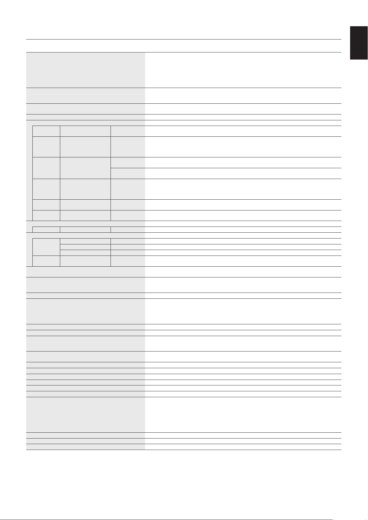
English-65
English
Specifications - V404-T
Product Specifications
LCD Module
Pixel Pitch:
Resolution:
Color:
Brightness:
Contrast Ratio:
Viewing Angle:
40"/101.61 cm diagonal
0.461 mm
1920 x 1080
Over 1073 million colors (depending on display card used)
440 cd/m
2
(Max.)@25°C
4000:1
89°(typ)@CR>10
Frequency Horizontal:
Vertical:
15.625/15.734 kHz, 31.5 kHz - 91.1 kHz
50.0 - 85.0 Hz (Analog Input)
24.0 - 85.0 Hz (Digital Input)
Pixel Clock Analog: 13.5 MHz, 25.0 MHz - 195.0 MHz
Digital: 25.0 MHz - 165.0 MHz (DVI), 25.0 MHz - 600.0 MHz (HDMI/DisplayPort)
Viewable Size 885.6 x 498.15 mm
Input Signal
DVI DVI-D 24pin Digital RGB DVI (HDCP1.4)
VGA60, SVGA60, XGA60, WXGA60, SXGA60, UXGA60*
1
, 1920X1080 (60Hz), 1080p, 1080i
DisplayPort DisplayPort Connector Digital RGB DisplayPort V1.2 (HDCP1.3)
VGA60, SVGA60, XGA60, WXGA60, SXGA60, UXGA60*
1
, WUXGA60*
1
, 1920x1080 (60 Hz),
1080p, 1080i, 720p@50Hz/60Hz, 576p@50Hz, 480p@60Hz, 3840x2160 (24Hz/30Hz/60Hz
(DisplayPort1.2))*
1,
*
4
VGA
(RGB)*
4
15pin Mini D-sub Analog RGB 0.7 Vp-p/75 ohm
VGA60, SVGA60, XGA60, WXGA60, SXGA60, UXGA60*
1
, WUXGA60*
1
, 1920X1080 (60Hz)
Sync Separate: TTL level (Pos./Neg.)
Composite sync on Green Video: 0.3 Vp-p Neg.
HDMI HDMI Connector Digital YUV
Digital RGB
HDMI (HDCP1.4/2.2)
VGA60, SVGA60, XGA60, WXGA60, SXGA60, UXGA60*
1
, WUXGA60*
1
, 1920x1080 (60 Hz),
1080p, 1080i, 720p@50Hz/60Hz, 576p@50Hz, 480p@60Hz, 576i@50Hz, 480i@60Hz,
3840x2160 (30Hz/24Hz/25Hz/60Hz (MODE2))*
1,
*
4
, 4096x2160 (24Hz)*
1,
*
4
VGA
(YPbPr)*
4
15pin Mini D-sub Component Y: 1.0 Vp-p/75ohm, Cb/Cr (Pb/Pr): 0.7 Vp-p/75 ohm
HDTV/DVD: 1080p, 1080i, 720p@50Hz/60Hz, 576p@50Hz, 480p@60Hz, 576i@50Hz, 480i@60Hz
VIDEO*
4
RCA port Composite 1.0 Vp-p/75 ohm
NTSC/PAL/SECAM/4.43NTSC/PAL60
Output Signal
DisplayPort DisplayPort Connector Digital RGB DisplayPort V1.2 (HDCP1.3)
AUDIO
AUDIO
Input
Stereo Mini Jack Analog Audio Stereo L/R 0.5 Vrms
HDMI Connector Digital Audio PCM 32, 44.1, 48 KHz (16/20/24bit)
DisplayPort Connector Digital Audio PCM 32, 44.1, 48 KHz (16/20/24bit)
AUDIO
Output
Stereo Mini Jack Analog Audio Stereo L/R 0.5 Vrms
Speaker Output External Speaker Jack 15 W + 15 W (8 ohm)
Internal Speaker 10 W + 10 W (Stereo)
Control RS-232C In:
LAN:
Remote IN:
9 Pin D-sub
RJ-45 10 BASE-T/100 BASE-TX x 2
Stereo Mini Jack 3.5 mm Ø
SD card Hub Port: microSD card. Up to 32GB microSDHC is supported.
USB Hub USB1:
USB2:
USB CM1 (2A):
USB CM2:
USB MP:
USB 2.0 Downstream port
USB 2.0 Upstream port
Power supply port, 5V/2A (max.)
USB service port for maintenance
Media Player/Firmware update port
Power Supply 2.7 - 1.1 A @ 100-240V AC, 50/60Hz
Power Consumption Normal operation: Approx. 75 W
Operational Environment Temperature*
2
:
Humidity:
Altitude:
0-35°C/32-95°F
20 - 80% (without condensation)
0 - 3000 m (Brightness may decrease with altitude)
Storage Environment Temperature:
Humidity:
-20-60°C/-4-140°F
10-90%(withoutcondensation)/90%-3.5%x(Temp-40°C)regardingover40°C
Dimension*
5
954.4 (W) x 567.0 (H) x 77.7 (D) mm/37.6 (W) x 22.3 (H) x 3.1 (D) inches
Weight 22.7 kg (50.0 lbs)
Detection method IR scanning method
Operating system Windows 7, Windows 8, Windows 8.1, Windows 10
Multi-touch More than 2 touches with Windows 7 (limited accuracy) or later version
PC connector USB V2.0
Protective glass Material:
Thickness:
Surface treatment:
Transparency:
Reflection rate:
Surface hardness:
Impact resistance*
6
:
Full-tempered glass
4.0 mm
Anti-glare coating (Front side)
More than 88%
≤ 6.5%
6 H
130 cm
VESA compatible mounting interface 300 mm x 300 mm (M6, 4 Holes)
Power Management VESA DPM
Power supply for Slot 2 type OPTION 16V/3.6 A
NOTE: Technical specifications are subject to change without notice.
*
1
: Compressed image.
*
2
: When you use option board accessories, please contact your supplier for detailed information.
*
3
: Reproduced text may look blurred.
*
4
: Common terminal.
*
5
: Measurements are of the monitor only and do not include removable parts that protrude.
*
6
: The distance of a steel ball (weight: 500 g) in one free fall without breaking.
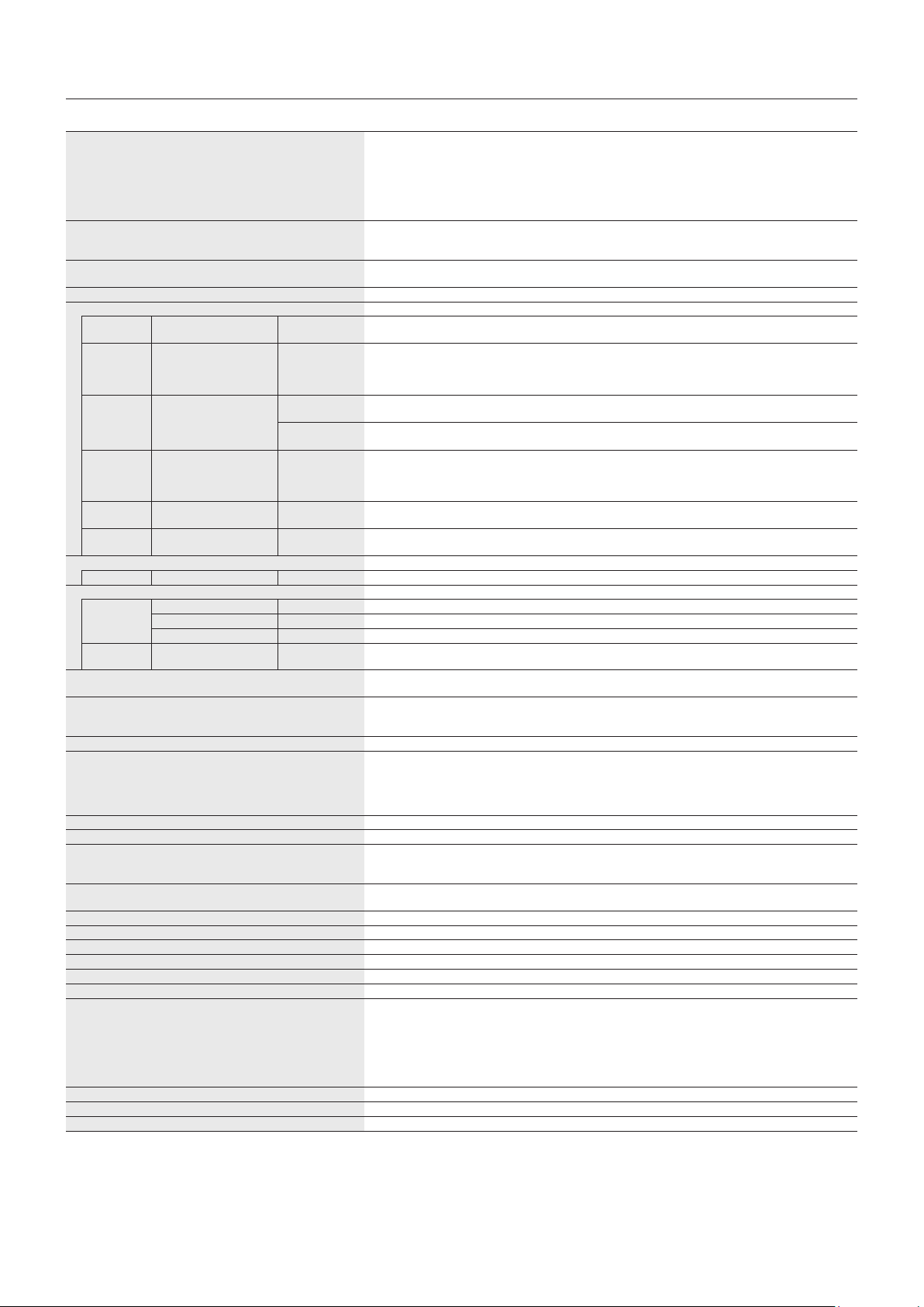
English-66
Specifications - V484-T
Product Specifications
LCD Module
Pixel Pitch:
Resolution:
Color:
Brightness:
Contrast Ratio:
Viewing Angle:
48"/120.94 cm diagonal
0.549 mm
1920 x 1080
Over 1073 million colors (depending on display card used)
440 cd/m
2
(Max.)@25°C
4000:1
89°(typ)@CR>10
Frequency Horizontal:
Vertical:
15.625/15.734 kHz, 31.5 kHz - 91.1 kHz
50.0 - 85.0 Hz (Analog Input)
24.0 - 85.0 Hz (Digital Input)
Pixel Clock Analog: 13.5 MHz, 25.0 MHz - 195.0 MHz
Digital: 25.0 MHz - 165.0 MHz (DVI), 25.0 MHz - 600.0 MHz (HDMI/DisplayPort)
Viewable Size 1054.08 x 592.92 mm
Input Signal
DVI DVI-D 24pin Digital RGB DVI (HDCP1.4)
VGA60, SVGA60, XGA60, WXGA60, SXGA60, UXGA60*
1
, 1920X1080 (60Hz), 1080p, 1080i
DisplayPort DisplayPort Connector Digital RGB DisplayPort V1.2 (HDCP1.3)
VGA60, SVGA60, XGA60, WXGA60, SXGA60, UXGA60*
1
, WUXGA60*
1
, 1920x1080 (60 Hz),
1080p, 1080i, 720p@50Hz/60Hz, 576p@50Hz, 480p@60Hz, 3840x2160 (24Hz/30Hz/60Hz
(DisplayPort1.2))*
1,
*
4
VGA
(RGB)*
4
15pin Mini D-sub Analog RGB 0.7 Vp-p/75 ohm
VGA60, SVGA60, XGA60, WXGA60, SXGA60, UXGA60*
1
, WUXGA60*
1
, 1920X1080 (60Hz)
Sync Separate: TTL level (Pos./Neg.)
Composite sync on Green Video: 0.3 Vp-p Neg.
HDMI HDMI Connector Digital YUV
Digital RGB
HDMI (HDCP1.4/2.2)
VGA60, SVGA60, XGA60, WXGA60, SXGA60, UXGA60*
1
, WUXGA60*
1
, 1920x1080 (60 Hz),
1080p, 1080i, 720p@50Hz/60Hz, 576p@50Hz, 480p@60Hz, 576i@50Hz, 480i@60Hz,
3840x2160 (30Hz/24Hz/25Hz/60Hz (MODE2))*
1,
*
4
, 4096x2160 (24Hz)*
1,
*
4
VGA
(YPbPr)*
4
15pin Mini D-sub Component Y: 1.0 Vp-p/75ohm, Cb/Cr (Pb/Pr): 0.7 Vp-p/75 ohm
HDTV/DVD: 1080p, 1080i, 720p@50Hz/60Hz, 576p@50Hz, 480p@60Hz, 576i@50Hz, 480i@60Hz
VIDEO*
4
RCA port Composite 1.0 Vp-p/75 ohm
NTSC/PAL/SECAM/4.43NTSC/PAL60
Output Signal
DisplayPort DisplayPort Connector Digital RGB DisplayPort V1.2 (HDCP1.3)
AUDIO
AUDIO
Input
Stereo Mini Jack Analog Audio Stereo L/R 0.5 Vrms
HDMI Connector Digital Audio PCM 32, 44.1, 48 KHz (16/20/24bit)
DisplayPort Connector Digital Audio PCM 32, 44.1, 48 KHz (16/20/24bit)
AUDIO
Output
Stereo Mini Jack Analog Audio Stereo L/R 0.5 Vrms
Speaker Output External Speaker Jack 15 W + 15 W (8 ohm)
Internal Speaker 10 W + 10 W (Stereo)
Control RS-232C In:
LAN:
Remote IN:
9 Pin D-sub
RJ-45 10 BASE-T/100 BASE-TX x 2
Stereo Mini Jack 3.5 mm Ø
SD card Hub Port: microSD card. Up to 32GB microSDHC is supported.
USB Hub USB1:
USB2:
USB CM1 (2A):
USB CM2:
USB MP:
USB 2.0 Downstream port
USB 2.0 Upstream port
Power supply port, 5V/2A (max.)
USB service port for maintenance
Media Player/Firmware update port
Power Supply 2.7 - 1.1 A @ 100-240V AC, 50/60Hz
Power Consumption Normal operation: Approx. 85 W
Operational Environment Temperature*
2
:
Humidity:
Altitude:
0-35°C/32-95°F
20 - 80% (without condensation)
0 - 3000 m (Brightness may decrease with altitude)
Storage Environment Temperature:
Humidity:
-20-60°C/-4-140°F
10-90%(withoutcondensation)/90%-3.5%x(Temp-40°C)regardingover40°C
Dimension*
5
1122.9 (W) x 661.7 (H) x 77.7 (D) mm/44.2 (W) x 26.1 (H) x 3.1 (D) inches
Weight 28.5 kg (62.8 lbs)
Detection method IR scanning method
Operating system Windows 7, Windows 8, Windows 8.1, Windows 10
Multi-touch More than 2 touches with Windows 7 (limited accuracy) or later version
PC connector USB V2.0
Protective glass Material:
Thickness:
Surface treatment:
Transparency:
Reflection rate:
Surface hardness:
Impact resistance*
6
:
Full-tempered glass
4.0 mm
Anti-glare coating (Front side)
More than 88%
≤ 6.5%
6 H
130 cm
VESA compatible mounting interface 300 mm x 300 mm (M6, 4 Holes)
Power Management VESA DPM
Power supply for Slot 2 type OPTION 16V/3.6 A
NOTE: Technical specifications are subject to change without notice.
*
1
: Compressed image.
*
2
: When you use option board accessories, please contact your supplier for detailed information.
*
3
: Reproduced text may look blurred.
*
4
: Common terminal.
*
5
: Measurements are of the monitor only and do not include removable parts that protrude.
*
6
: The distance of a steel ball (weight: 500 g) in one free fall without breaking.

English-67
English
Specifications - V554-T
Product Specifications
LCD Module
Pixel Pitch:
Resolution:
Color:
Brightness:
Contrast Ratio:
Viewing Angle:
55"/138.78 cm diagonal
0.630 mm
1920 x 1080
Over 1073 million colors (depending on display card used)
440 cd/m
2
(Max.)@25°C
1200:1
89°(typ)@CR>10
Frequency Horizontal:
Vertical:
15.625/15.734 kHz, 31.5 kHz - 91.1 kHz
50.0 - 85.0 Hz (Analog Input)
24.0 - 85.0 Hz (Digital Input)
Pixel Clock Analog: 13.5 MHz, 25.0 MHz - 195.0 MHz
Digital: 25.0 MHz - 165.0 MHz (DVI), 25.0 MHz - 600.0 MHz (HDMI/DisplayPort)
Viewable Size 1209.6 x 680.4 mm
Input Signal
DVI DVI-D 24pin Digital RGB DVI (HDCP1.4)
VGA60, SVGA60, XGA60, WXGA60, SXGA60, UXGA60*
1
, 1920X1080 (60Hz), 1080p, 1080i
DisplayPort DisplayPort Connector Digital RGB DisplayPort V1.2 (HDCP1.3)
VGA60, SVGA60, XGA60, WXGA60, SXGA60, UXGA60*
1
, WUXGA60*
1
, 1920x1080 (60 Hz),
1080p, 1080i, 720p@50Hz/60Hz, 576p@50Hz, 480p@60Hz, 3840x2160 (24Hz/30Hz/60Hz
(DisplayPort1.2))*
1,
*
4
VGA
(RGB)*
4
15pin Mini D-sub Analog RGB 0.7 Vp-p/75 ohm
VGA60, SVGA60, XGA60, WXGA60, SXGA60, UXGA60*
1
, WUXGA60*
1
, 1920X1080 (60Hz)
Sync Separate: TTL level (Pos./Neg.)
Composite sync on Green Video: 0.3 Vp-p Neg.
HDMI HDMI Connector Digital YUV
Digital RGB
HDMI (HDCP1.4/2.2)
VGA60, SVGA60, XGA60, WXGA60, SXGA60, UXGA60*
1
, WUXGA60*
1
, 1920x1080 (60 Hz),
1080p, 1080i, 720p@50Hz/60Hz, 576p@50Hz, 480p@60Hz, 576i@50Hz, 480i@60Hz,
3840x2160 (30Hz/24Hz/25Hz/60Hz (MODE2))*
1,
*
4
, 4096x2160 (24Hz)*
1,
*
4
VGA
(YPbPr)*
4
15pin Mini D-sub Component Y: 1.0 Vp-p/75ohm, Cb/Cr (Pb/Pr): 0.7 Vp-p/75 ohm
HDTV/DVD: 1080p, 1080i, 720p@50Hz/60Hz, 576p@50Hz, 480p@60Hz, 576i@50Hz, 480i@60Hz
VIDEO*
4
RCA port Composite 1.0 Vp-p/75 ohm
NTSC/PAL/SECAM/4.43NTSC/PAL60
Output Signal
DisplayPort DisplayPort Connector Digital RGB DisplayPort V1.2 (HDCP1.3)
AUDIO
AUDIO
Input
Stereo Mini Jack Analog Audio Stereo L/R 0.5 Vrms
HDMI Connector Digital Audio PCM 32, 44.1, 48 KHz (16/20/24bit)
DisplayPort Connector Digital Audio PCM 32, 44.1, 48 KHz (16/20/24bit)
AUDIO
Output
Stereo Mini Jack Analog Audio Stereo L/R 0.5 Vrms
Speaker Output External Speaker Jack 15 W + 15 W (8 ohm)
Internal Speaker 10 W + 10 W (Stereo)
Control RS-232C In:
LAN:
Remote IN:
9 Pin D-sub
RJ-45 10 BASE-T/100 BASE-TX x 2
Stereo Mini Jack 3.5 mm Ø
SD card Hub Port: microSD card. Up to 32GB microSDHC is supported.
USB Hub USB1:
USB2:
USB CM1 (2A):
USB CM2:
USB MP:
USB 2.0 Downstream port
USB 2.0 Upstream port
Power supply port, 5V/2A (max.)
USB service port for maintenance
Media Player/Firmware update port
Power Supply 3.3 - 1.4 A @ 100-240V AC, 50/60Hz
Power Consumption Normal operation: Approx. 110 W
Operational Environment Temperature*
2
:
Humidity:
Altitude:
0-35°C/32-95°F
20 - 80% (without condensation)
0 - 3000 m (Brightness may decrease with altitude)
Storage Environment Temperature:
Humidity:
-20-60°C/-4-140°F
10-90%(withoutcondensation)/90%-3.5%x(Temp-40°C)regardingover40°C
Dimension*
5
1278.6 (W) x 749.4 (H) x 85.9 (D) mm/50.3 (W) x 29.5 (H) x 3.4 (D) inches
Weight 39.0 kg (86.0 lbs)
Detection method IR scanning method
Operating system Windows 7, Windows 8, Windows 8.1, Windows 10
Multi-touch More than 2 touches with Windows 7 (limited accuracy) or later version
PC connector USB V2.0
Protective glass Material:
Thickness:
Surface treatment:
Transparency:
Reflection rate:
Surface hardness:
Impact resistance*
6
:
Full-tempered glass
4.0 mm
Anti-glare coating (Front side)
More than 88%
≤ 6.5%
6 H
130 cm
VESA compatible mounting interface 300 mm x 300 mm (M6, 4 Holes)
Power Management VESA DPM
Power supply for Slot 2 type OPTION 16V/3.6 A
NOTE: Technical specifications are subject to change without notice.
*
1
: Compressed image.
*
2
: When you use option board accessories, please contact your supplier for detailed information.
*
3
: Reproduced text may look blurred.
*
4
: Common terminal.
*
5
: Measurements are of the monitor only and do not include removable parts that protrude.
*
6
: The distance of a steel ball (weight: 500 g) in one free fall without breaking.

English-68
NEC DISPLAY SOLUTIONS is strongly committed to environmental protection and sees recycling as one of the company’s top
priorities in trying to minimize the burden placed on the environment. We are engaged in developing environmentally-friendly
products, and always strive to help define and comply with the latest independent standards from agencies such as ISO
(International Organisation for Standardization) and TCO (Swedish Trades Union).
Disposing of your old NEC product
The aim of recycling is to gain an environmental benefit by means of re-use, upgrading, reconditioning or reclamation of
material. Dedicated recycling sites ensure that environmentally harmful components are properly handled and securely
disposed. To ensure the best recycling of our products, NEC DISPLAY SOLUTIONS offers a variety of recycling procedures
and gives advice on how to handle the product in an environmentally sensitive way, once it has reached the end of its life.
All required information concerning the disposal of the product and country-specific information on recycling facilities can be
found on our following websites:
https://www.nec-display-solutions.com/p/greenvision/en/greenvision.xhtml (in Europe),
https://www.nec-display.com (in Japan) or
http://www.necdisplay.com (in USA).
Energy Saving
This monitor features an advanced energy saving capability. When a Display Power Management signal is sent to the monitor,
the Energy Saving mode is activated. The monitor enters a single Energy Saving mode.
For additional information visit:
http://www.necdisplay.com/ (in USA)
http://www.nec-display-solutions.com/ (in Europe)
https://www.nec-display.com/global/index.html (Global)
For ErP requirement/For ErP (Network standby) requirement:
Except for the conditions below: The monitor is using an option board.
INPUT DETECT is set to a setting except for NONE.
USB POWER is set to ON.
DisplayPort in the TERMINAL SETTINGS is set to MST.
Power consumption (Glowing amber): 2.0 W or less (with 1 port connection)/3.0 W or less (with all ports connection).
Time for power management function: 10 sec. (Default setting)
Power consumption (Blinking amber): 0.5 W or less.
Time for power management function: 3 min. (Default setting)
(Except for a condition that the monitor has plural signal inputs.)
Manufacturer’s Recycling and Energy Information
English-69
English
WEEE Mark (European Directive 2012/19/EU and amendments)
Disposing of your used product: In the European Union
EU-wide legislation as implemented in each Member State requires that used electrical and electronic products
carrying the mark (left) must be disposed of separately from normal household waste. This includes monitors
and electrical accessories, such as signal cables or power cords. When you dispose of such products, please
follow the guidance of your local a uthority or ask the shop where you purchased the product, or if applicable,
follow applicable legislation or agreement you may have. The mark on electrical and electronic products may
only apply to the current European Union Member States.
Outside the European Union
If you wish to dispose of used electrical and electronic products outside the European Union, please contact your local authority
and ask for the correct method of disposal.
For EU: The crossed-out wheeled bin implies that used batteries should not be put to the general household
waste! There is a separate collection system for used batteries, to allow proper treatment and recycling in
accordance with legislation.
According to EU directive 2006/66/EC and amendments, the battery can’t be disposed improperly. The battery shall be
separated to collect by local service.

English-70
1. MPEG-4 AVC
THIS PRODUCT IS LICENSED UNDER THE AVC PATENT PORTFOLIO LICENSE FOR THE PERSONAL USE OF
A CONSUMER OR OTHER USES IN WHICH IT DOES NOT RECEIVE REMUNERATION TO (i) ENCODE VIDEO IN
COMPLIANCE WITH THE AVC STANDARD (“AVC VIDEO”) AND/OR (ii) DECODE AVC VIDEO THAT WAS ENCODED BY
A CONSUMER ENGAGED IN A PERSONAL ACTIVITY AND/OR WAS OBTAINED FROM A VIDEO PROVIDER LICENSED
TO PROVIDE AVC VIDEO. NO LICENSE IS GRANTED OR SHALL BE IMPLIED FOR ANY OTHER USE. ADDITIONAL
INFORMATION MAY BE OBTAINED FROM MPEG LA, L.L.C. SEE HTTP://WWW.MPEGLA.COM
2. MPEG-4 Visual
THIS PRODUCT IS LICENSED UNDER THE MPEG-4 VISUAL PATENT PORTFOLIO LICENSE FOR THE PERSONAL AND
NON-COMMERCIAL USE OF A CONSUMER FOR (i) ENCODING VIDEO IN COMPLIANCE WITH THE MPEG-4 VISUAL
STANDARD (“MPEG-4 VIDEO”) AND/OR (ii) DECODING MPEG-4 VIDEO THAT WAS ENCODED BY A CONSUMER
ENGAGED IN A PERSONAL AND NONCOMMERCIAL ACTIVITY AND/OR WAS OBTAINED FROM A VIDEO PROVIDER
LICENSED BY MPEG LA TO PROVIDE MPEG-4 VIDEO. NO LICENSE IS GRANTED OR SHALL BE IMPLIED FOR
ANY OTHER USE. ADDITIONAL INFORMATION INCLUDING THAT RELATING TO PROMOTIONAL, INTERNAL AND
COMMERCIAL USES AND LICENSING MAY BE OBTAINED FROM MPEG LA, LLC. SEE HTTP://WWW.MPEGLA.COM.
[Notice] About the MPEG-4 AVC,
MPEG-4 Visual license included in this product