Loading ...
Loading ...
Loading ...
31-5000553 Rev. 1 19
ENGLISH
Wire Connections (cont.)
• Outdoor units are of parallel connection via three lines with polarity.
• The main unit, central control and all indoor units are of parallel connection via two lines without polarity.
• There are three ways of connecting the line control and indoor units:
A. One wired controller to control multiple units, i.e. 2-9 indoor units, as shown in the figure at the top of page 18, (1-3
indoor units). The indoor unit 3 is the wire controlled main unit and others are the wired controlled sub units. The wired
controller and the main unit (directly connected to the indoor unit of wired controller) are connected via three wires
with polarity. Other indoor units and the main unit are connected via three lines with polarity. SW01 on the main unit of
wired control is set to 0 while SW01 on other sub units of wired control are set to 1, 2 and so on in turn. (Please refer to
the code setting A at page 14)
B. One wired controller controls one indoor unit, as shown in the figure at the bottom of page 18 (indoor unit 4-8). The
indoor units and the wired controller are connected via three lines with polarity.
C. Two wired controllers control one indoor unit, as shown in the figure (page 18) (indoor unit 9). Either of the wired
controllers can be set to be the main wired controller while the other is set to be the auxiliary wired controller. The main
wired controller and indoor units, and the main and auxiliary line controls are connected via three lines with polarity.
Note: For DC motor/low ESP duct type, the PCB comes with the terminal blocks. Please be sure to pay attention to do
the wiring according to the labels. The power lines and signal lines go through the metal wire hole separately with the
protective sleeve of the connecting line.
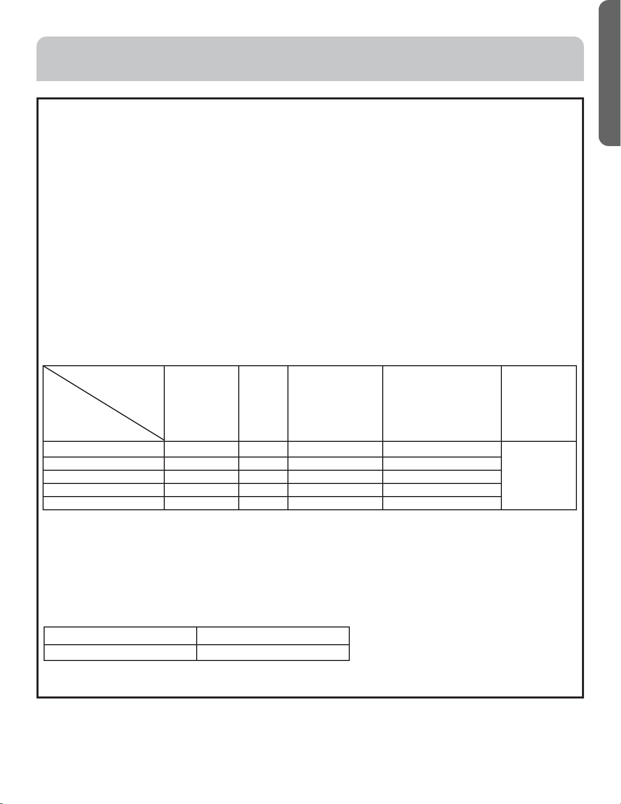
Wire gauge size and breaker size for total indoor amp draw.
Current NEC guidelines and local codes will trump this chart.
• The electrical power line and signal lines must be tightened.
• Every indoor unit must have a ground connection.
• The power wire should be size up if it exceeds the permissible length.
• Shielding of the wire of all the indoor and outdoor units should be connected and grounded at one point in the outdoor
unit. The far end of the shielding wire should be wrapped back and taped.
• Signal lines should not exceed 3280ft (1000m).
Wired Controller ABC Chart
• The shielding layer of the controller wire must be grounded at the equipment end, and taped back at the terminal end.
• The total length of the controller wire shall not be more than 820ft (250m).
Items Cross Section
(mm²)
Length
(mm)
Rated Current of
Overflow Breaker
(A)
Rated Current of
Residual Circuit
Breaker(A)
GroundFault
Interrupter (mA)
Response Time (S)
Cross
Sectional Area
of Signal Line
< 6 2.5 20 6 6 A, 30 mA, 0.1S or below
2 core X0.75-
2.0mm2
6 and < 10
2.5 20 10 10 A, 30 mA, 0.1S or below
10 and < 16
4 25 16 16 A, 30 mA, 0.1S or below
16 and < 25
6 30 25 25 A, 30 mA, 0.1S or below
25 and < 35
10 50 32 32 A, 30 mA, 0.1S or below
Total Current
of Indoor
Units (A)
Length ofControllerWire ft(m)
Wiring Dimensions AWG (mm²)
820 (250)
18 (0.75) x 3 core shielding line
ELECTRICAL WIRING
Loading ...
Loading ...
Loading ...