Loading ...
Loading ...
Loading ...
en Installation and connection
10
Converting the cooktop from Nat. Gas to
Universal LPG
All work involved in installation, setting and adaptation
to a different gas type must be carried out by
authorised personnel from our Service Centre and must
comply with current regulations and the conditions laid
down by the local gas company.
Before conversion the cooktop must be disconnected
from the electricity and gas valves must be turned to the
OFF position.
Important: After finishing, stick the sticker, indicating
the new gas type, close to the specifications plate.
Replacing the injectors
Request change-over injectors from our customer
service deparment (refer injector chart below for sizes).
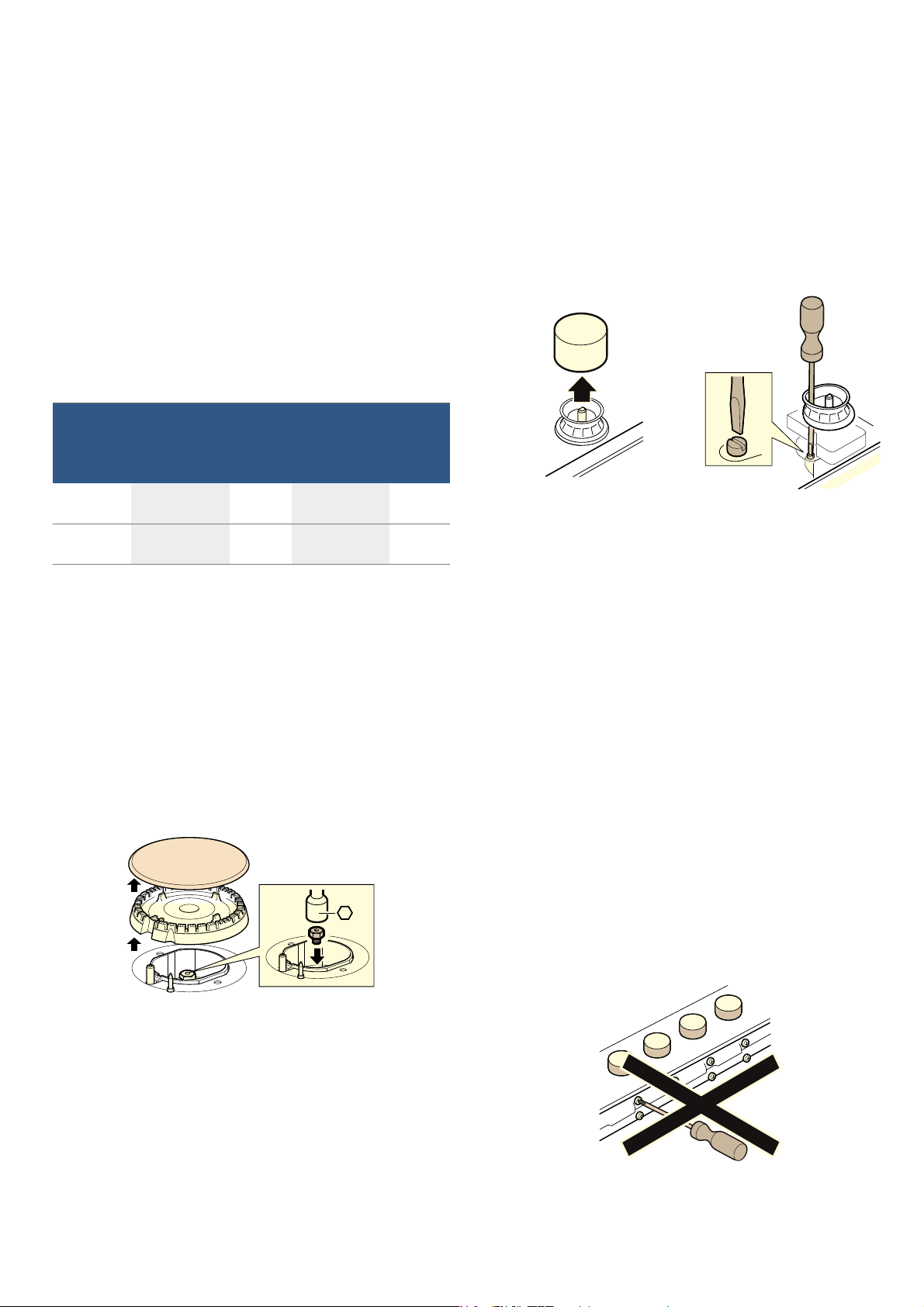
1. Remove all pan supports, burner caps and
distributors.
2. To replace the injectors, use the key that is available
from our technical service with code 340847 (for
double-flame burners 340808). See table. It is
important to make sure that the injector does not
become detached during removal or fastening. They
must be properly tightened to ensure that there are
no leaks.
With these burners, there is no need to adjust the
primary air.
3. Fasten the distributors and burner caps to the
corresponding burners. In addition to this, put the
pan supports in place on the corresponding burners.
Adjusting the gas valves
1. Turn the control knobs to the lowest setting.
2. Remove the control knobs from the gas valves. A
flexible rubber sealing ring will be visible. Push down
with the tip of a screwdriver on the gas valve's
setting screw.
Never remove the sealing ring. Sealing rings
prevent liquids and dirt from finding their way into
the appliance and impairing its ability to function
properly.
3. Adjust the minimum ring setting by turning the by-
pass screw using a flat head screwdriver.
To adjust the minimum flame for N.G. replace the
control knob onto the spindle, light the gas and turn
the control knob to the small flame position. Screw
the adjustment screw anti-clockwise to estabilish a
minimum stable flame position. The flame should
remain alight and not burn back to the injector
when the valve is turned quickly from ‘Full On’ to
the “Minimum flame” position and back a few
times. To adjust the minimum flame position for
ULPG the screw must be fully tightened down
clockwise.
If the by-pass screw cannot be accessed, disassemble
the grease drip tray, which is fixed to the rest of the hob
using a clip and screw mounting system. The following
steps must be taken to remove it:
1. Remove all pan supports, burner caps, diffusers and
control knobs.
2. Loosen the screws on the burners.
3. To assemble the grease splash tray again, proceed
in the reverse order to removal.
It is important that all the seals are refitted to form a
seal.
Never remove the gas tap axle. In the event of damage,
the gas valve must be completely replaced.
Natural Gas Universal LPG
Hourly Gas
Consumption
(MJ)
Injector
mark
Hourly Gas
Consumption
(MJ)
Injector
mark
Economy
burner
3.80 90 3.50 50
High- out-
put burner
11.25 155 10.00 85
Loading ...
Loading ...
Loading ...