Loading ...
GENERAL INFORMATION
This appliance shall only be used in an above ground
open-air situation with natural ventilation, without
stagnant areas, where gas leakage and products of
combustion are rapidly dispersed by wind and natural
convection.
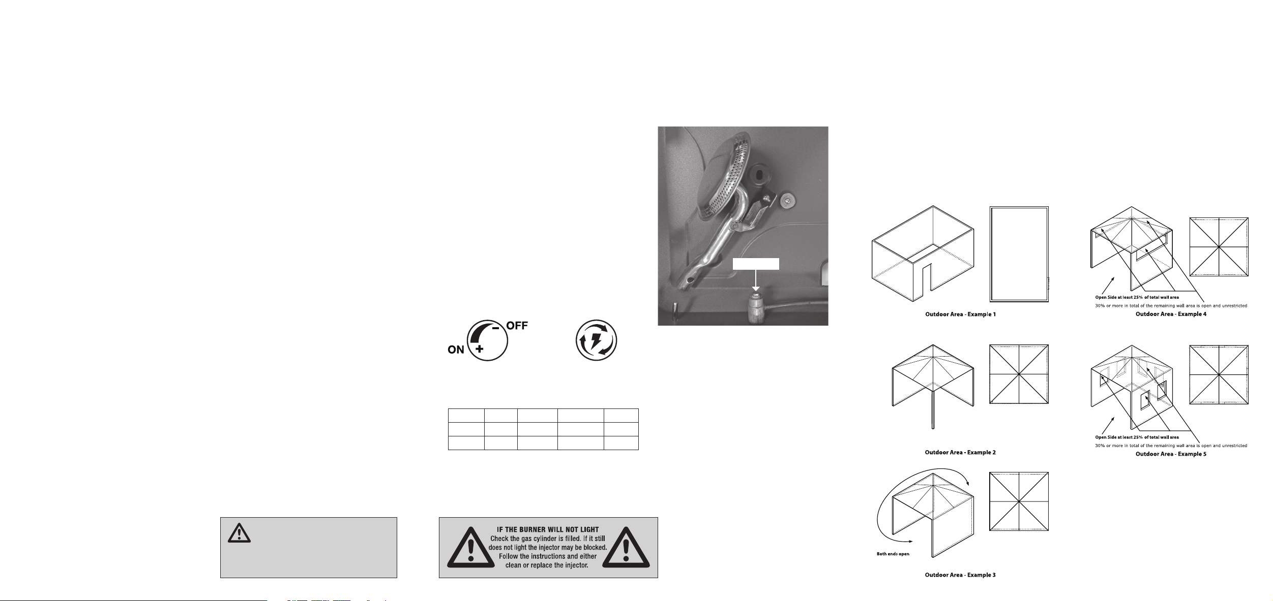
Any enclosure in which the appliance is used shall
comply with the following:
An enclosure with walls on all sides, but at least one
permanent opening at ground level and no overhead
cover (see Example 1).
Within a partial enclosure that includes an overhead cover
and no more than two walls (see Example 2 & 3).
Within a partial enclosure that includes an overhead
cover and more than two walls, the following will
apply:
at least 25% of the total wall area is completely open,
and at least 30% of the remaining wall area is open and
unrestricted (see Example 4 & 5).
In the case of balconies, at least 20% of the total wall
area shall be and remain open and unrestricted.
DIAGRAMMATIC REPRESENTATIONS OF OUTDOOR AREAS
The following figures are diagrammatic representations of outdoor areas. Rectangular areas have been used in these
figures – the same principles apply to any other shaped area.
INSTRUCTIONS
Read these instructions for use carefully. Familiarise
yourself with the appliance before connecting it to its gas
container. Keep these instructions for future reference.
1. Remove appliance from carton and remove any
transit protection material.
2. Open the lid to the vertical position, fold out the
windshield and engage the clips with the slots in the
side of the body.
3. Lift the front edge of the wire trivet to remove the
hose from its storage position and replace the
trivet. Check the “O” rings for any damage before
connecting hose. Connect the hose to the appliance
by pushing the hose fitting into the inlet connector,
then tightening the knurled nut until hand tight and
firm.
4. Check that the control valves for the burners are
turned OFF (clockwise for off).
5. Connect the hose to the cylinder and use a spanner
to tighten firmly.
6. Ensure the chrome wire lid latches or feet are in
position to maintain clearance between the appliance
and the support surface and for good airflow and
correct operation.
This appliance should only be operated on a hard,
flat, level surface.
a. The appliance area must be kept clear and
free of combustible materials, gasoline and other
flammable vapours and liquids.
b. Gas orifices and burner must be kept clear of dirt
and cobwebs. Flow of combustion and
ventilation air through the perforated portions of
the appliance must not be obstructed.
c. Any cleaning agent used on the appliance should
be of a non-combustible and non-corrosive
nature.
7. Proper clearance from combustible materials must
be maintained at all times. The minimum clearances
are as follows:
Minimum Clearance from Combustibles:
Rear 600mm Side 600mm Top 600mm
Combustible materials are considered to be wood,
compressed paper, plant fibres, plastic, plexiglas or
other materials capable of being ignited and burned.
Such materials shall be considered combustible even
though flame proofed, fire-retardant treated or plastered.
Additional clearance may be required for glass, painted
surfaces and other materials which may be damaged by
radiant or convection heat.
LIGHTING & BURNER ADJUSTMENT
1. Open the cylinder control valve about one full turn
ensuring that all the control knobs on the stove are
turned OFF at this point. DO NOT ATTEMPT TO
LIGHT THE STOVE!
2. To check for leaks on all connections use a solution
of soapy water (dish washing liquid and water is
fine). Brush it on or use a spray bottle. Ensure the
connections have a good coating.
3. If the connection is leaking, bubbles will start to grow
in the soapy solution. If this happens shut off the gas
supply at the cylinder.
4. Tighten the connections using a spanner then repeat
steps 1-2. The connection is gas tight when no
bubbles grow around the gas connection.
5. Each burner can be operated independently by
turning the control valve on (rotating the knob anti-
clockwise about one turn) and rotating the igniter
knob clockwise or applying a lighted match to the
burner. The flame can be regulated by opening or
closing the valve.
6. If the burner fails to ignite after several attempts,
turn the control knob to OFF and wait a few minutes
before attempting re-ignition.
7. Turn the control knob anti-clockwise to increase the
flame, or clock-wise to decrease the flame.
8. IMPORTANT: When turning the stove off at
completion of use, the gas supply should be first
turned off at the cylinder, and all gas in the hose
burnt away before closing the valves on the stove.
Leaving the gas in the hose can cause injector
blockage. Note: If re-ignition if necessary while the
stove is still hot, you must wait for a minimum of 5
minutes before commencing to re-ignite (this allows
accumulated gas fumes to clear).
REGULAR MAINTENANCE
Clean the body of your appliance using a cotton cloth
soaked in soapy hot water. Never use abrasive or
flammable cleaning products. Use a soft brush to clean
the burner.
STORAGE
When the appliance is not used it must be
stored in a suitable area to protect it from any risk of
deterioration. Keep it in a well ventilated area and out of
reach of children.
HANDY HINTS
a. The hose connections, cylinder valve outlet
connection and appliance inlet connection should
be kept clean. If grit or dirt is present when the
connections are made, the rubber seals at each end
of the hose may be damaged.
b. To clear blocked injector wash in petrol or use
compressed air to blow out obstruction. Do not use
wires or prickers. If washing is unsuccessful, fit new
injector.
c. Check for gas leaks with SOAPY WATER. DO NOT
USE A FLAME.
d. Ensure that the area in which the appliance is to be
used is well ventilated and DO NOT use as a space
heater in tent, caravan, etc.
e. Ensure the appliance is completely extinguished
before disconnecting from the cylinder.
f. DO NOT place the appliance closer than 60cm from
ceiling or flammable material.
g. Avoid moving the appliance during use as this can
cause large flames.
h. Allow the appliance to cool down after use before
touching the burners, trivet, windshields or folding up
for transportation.
WARNING
Be very careful when turning the burner down.
Visually check to ensure the flame does not go out.
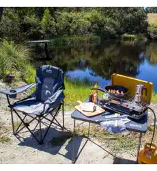
INJECTOR REPLACEMENT
If the burner will not light the injector may be blocked.
1. Undo and remove the burner screw on the
underside of the body.
2. With a small shifter remove the injector from the gas
valve and either clean or replace it (refer to Handy
Hints).
3. Re-attach the burner.
SAFE APPLIANCE LOCATIONS
GAS CONSUMPTION
Burners g/h MJ/h BTU Injector
x 2
390 g/h 19.6 MJ/h 18,956 BTU 0.20mm
x 1
105 g/h 5.5 MJ/h 5,000 BTU 0.20mm
KNOB MARKINGS
INJECTOR
IGNITER MARKINGS