Loading ...
Loading ...
Loading ...
10
OPERATING PROCEDURES & MAINTENANCE
UNPACKING YOUR ICE MAKER
1. Remove the exterior and interior packaging. Check if all the accessories, including instruction
manual, ic e scoop, white water inlet pipe, 4 ways to 2 ways water quick connector and the wat er
draining pipe, etc., are inside or not. If any parts are missing, please contact our customer service.
2. Remove the tapes for fixing the door and inner c abinet, ice scoop, etc.. Roughly clean the inner
cabinet & ice scoop with wet clothe.
3. Put the ice maker on
a level & flat flo or, without direct sunlight and other sources of heat (i.e.: stove,
furnace, radiator). Maker sure that there is at least 20cm gap between the air outlet and the
obstacles, and at least 5 cm between Left/Right side and the wall.
4. Allow 4 hours for the refrigerant fluid to settle before plugging the ice maker in if the unit maybe fall
upside down during shipping or transport ation.
5. The appliance must be positioned so that the plug is accessible.
WARNING: connect to the potable wat er supplying only. Only use drinking water.
INSTALLATION LOCATION REQUIREMENT
a) This unit is not for outdoor use. Keep the proper room temperature and inlet water
temperature accord ing to above specification table. Otherwise it will affect the ice making performance.
b) This unit should not be located near any heat resource.
c) The unit should be located on a firm & level foundation at normal counter top height.
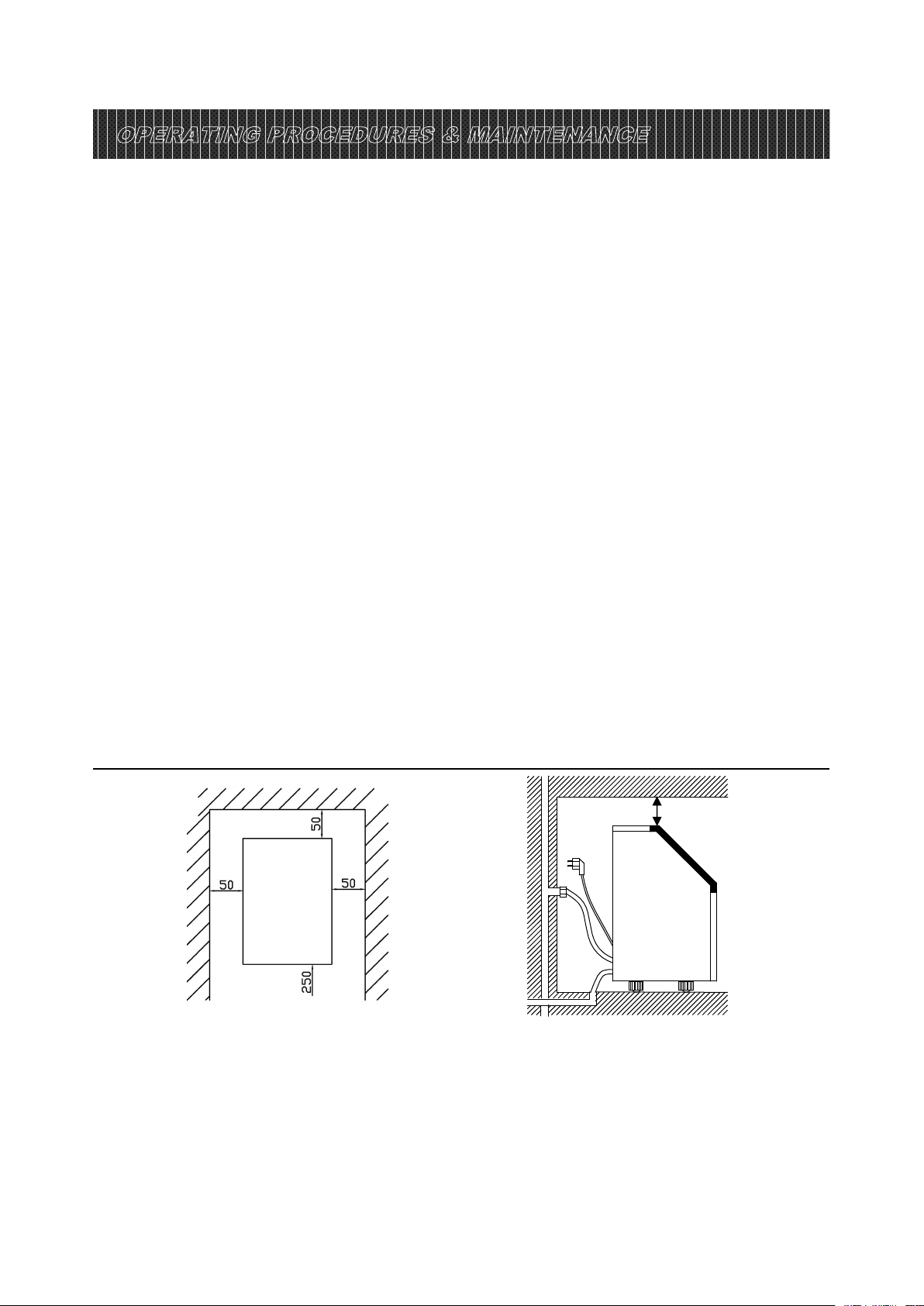
d) There must be at least 5CM clearance a
t rear side for connection and 25 CM clearance in
front to open the door and keep good air circulati on.
e) Do not put anything on the top of the ice maker.
To ensure proper ventilation f or your ice maker, the front of the unit must be c ompletely unobstructed
(at least 20CM free space). Allow at least 50 mm clearance at rear, and 50 mm at top and sides for
proper air circulation. The installation should allow the ic e maker to be pulled forward for servicing if
necessary.
When installing the ice maker under a counte r, follow the recommended spacing dimensions shown
above. Plac e electrical and water supplies and drain f ixtures in t
he recommended locations as shown.
Side view (mm)
(mm)
40
40
Installation clearance
top view (1:10) (mm)
Loading ...
Loading ...
Loading ...