WATER FILTRATION
SYSTEM
49-50326 10-16 GEA
SAFETY INFORMATION .........3
SYSTEM OVERVIEW .............4
INSTALLATION INSTRUCTIONS
Cold Water Connection .................4
Control Valve Installation ...............6
Mounting the System ...................8
Filter Change Light ....................9
Filter Replacement .....................9
Flush Procedure .......................9
TROUBLESHOOTING TIPS ......10
WARRANTY ......................12
CONSUMER SUPPORT ..........14
GXK285JBL System is certified
by IAPMO R&T against NSF/ANSI
Standards 42, 53, and 401 for the
reduction of claims specified on
the performance data sheet and at
iapmort.org.
GE is a trademark of the General Electric Company. Manufactured under trademark license.
ENGLISH/ESPAÑOL
OWNER’S MANUAL
& INSTALLATION
INSTRUCTIONS
GXK285JBL
PLATINUM SEAL
WATER QUALITY
I
A
P
M
O
R
E
S
E
A
R
C
H
A
N
D
T
E
S
T
I
N
G
™

2 49-50326
THANK YOU FOR MAKING GE APPLIANCES A PART OF YOUR HOME.
Whether you grew up with GE Appliances, or this is your first, we’re happy to have you in the family.
We take pride in the craftsmanship, innovation and design that goes into every GE Appliances
product, and we think you will too.
49-50326 3
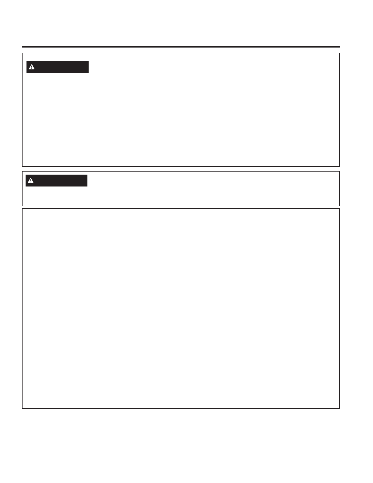
SAVE THESE INSTRUCTIONS
IMPORTANT SAFETY INFORMATION
READ ALL INSTRUCTIONS BEFORE USING
SAFETY INFORMATION
IMPORTANT SAFETY INSTRUCTIONS
To reduce the risk of fire, explosion, electric shock, or injury when
using your system follow these basic safety precautions:
To reduce the risk of injury when using your system follow these basic safety precautions
.
To reduce the risk associated with choking, do not
allow children under 3 years of age to have access
to small parts during the installation of this product.
To reduce the risk associated with the ingestion
of contaminants, do not use with water that is
microbiologically unsafe or of unknown quality
without adequate disinfection before or after the
system.
To reduce the risk associated with hazardous
voltage due to an installer drilling through existing
electric wiring or water pipes in the area of
installation, do not install near electric wiring or
piping which may be in path of a drilling tool when
selecting the position to mount the system bracket.
If this device is not maintained and operated as
specified in the owner’s manual, there is a risk of
exposure to contaminants. For more information,
visit the manufacturer’s internet website at www.
geappliances.com or the California State Water
Resources Control Boards’ internet website at www.
waterboards.ca.gov.
NOTICE:
Read and follow Use Instructions before installation
and use of this system.
Installation and use MUST comply with all state and
local plumbing codes.
Do not use on a hot water supply (100°F max.).
Install on a cold water line only.
Protect from freezing, remove filter cartridge when
temperatures are expected to drop below 35° F
(1.7° C).
Do not install if water pressure exceeds 125psi (8.8
Kg/cm
2
). If your water pressure exceeds 80 psi (5.6
Kg/cm
2
), you must install a pressure limiting valve.
Contact a plumbing professional if you are uncertain
how to check your water pressure.
Do not install systems in areas where ambient
temperatures may go above 110° F (43.3° C).
The disposable filter cartridge should be replaced
every 6 months, at the rated capacity or sooner if a
noticeable reduction in flow rate occurs.
Where a back flow prevention device is installed on a
water system, a device for controlling pressure due to
thermal expansion must be installed.
Do not install where water hammer conditions may
occur. If water hammer conditions exist you must
install a water hammer arrester. Contact a plumbing
professional if you are uncertain how to check for this
condition.
Ensure all tubing and fittings are secure and free of
leaks.
On plastic fittings, never use pipe sealant or pipe
dope. Use PTFE thread tape only as pipe dope may
deteriorate the plastic.
Do not use a torch or other high temperature sources
near system, cartridges, plastic fittings or plastic
plumbing.
Do not install in direct sunlight or outdoors.
Do not install near water pipes which will be in path
of a drilling tool when selecting the position to mount
the bracket.
Mount system in such a position as to prevent it
from being struck by other items used in the area of
installation.
Ensure that the location and fasteners will support
the weight of the system when installed and full of
water.
CAUTION
WARNING
To reduce the risk of physical injury, depressurize system as shown in manual prior to cartridge removal.
4 49-50326
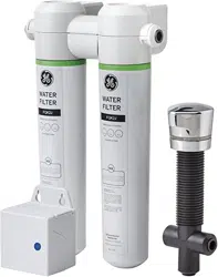
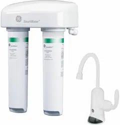
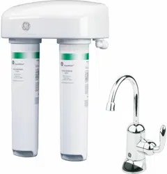
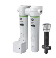
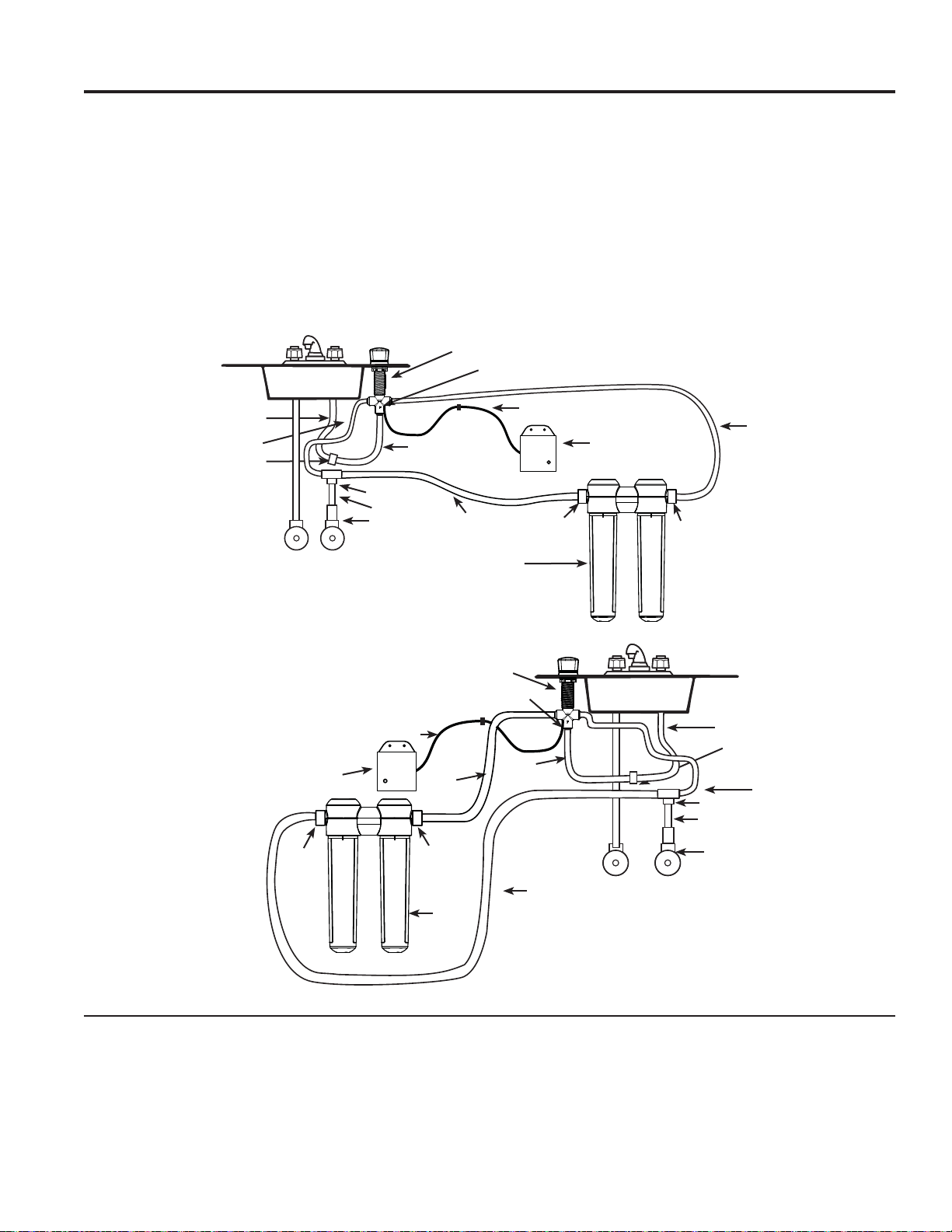
How it works
SYSTEM OVERVIEW: How it works
This system allows you to choose between filtered
and unfiltered water from your existing kitchen
faucet. The system consists of a control valve, timer,
and filters. The existing water line is split into two lines.
One line passes through the filtration system to the
control valve. The other line connects directly to the
control valve.
When the control valve is pointing away from your
kitchen faucet, normal unfiltered water is dispensed.
When the control valve is pointing toward your kitchen
faucet, filtered water is dispensed.
You will notice a slightly slower flow of water when
filtered water is being dispensed.
The base of the control valve will flash red when its time
to change filters and batteries. When it double flashes,
6 months have passed and its time to replace the filters.
When it flashes a single fading flash, 1 year has passed
and it is time to replace the filters and the timer batteries.
Specification Guidelines
Many bad tastes and/or odors are reduced in water
using activated carbon filter canisters. They are most
often used to reduce chlorine taste and odor. They can
also reduce other undesirable elements from drinking
water supplies.
NOTE: Small amounts of hydrogen sulfide (noticeable
as “rotten egg” odor) may be reduced by taste and
odor filters for a short time, but the carbon media is
quickly exhausted. Other water conditioning equipment
is usually required for the continuous treatment of
hydrogen sulfide.
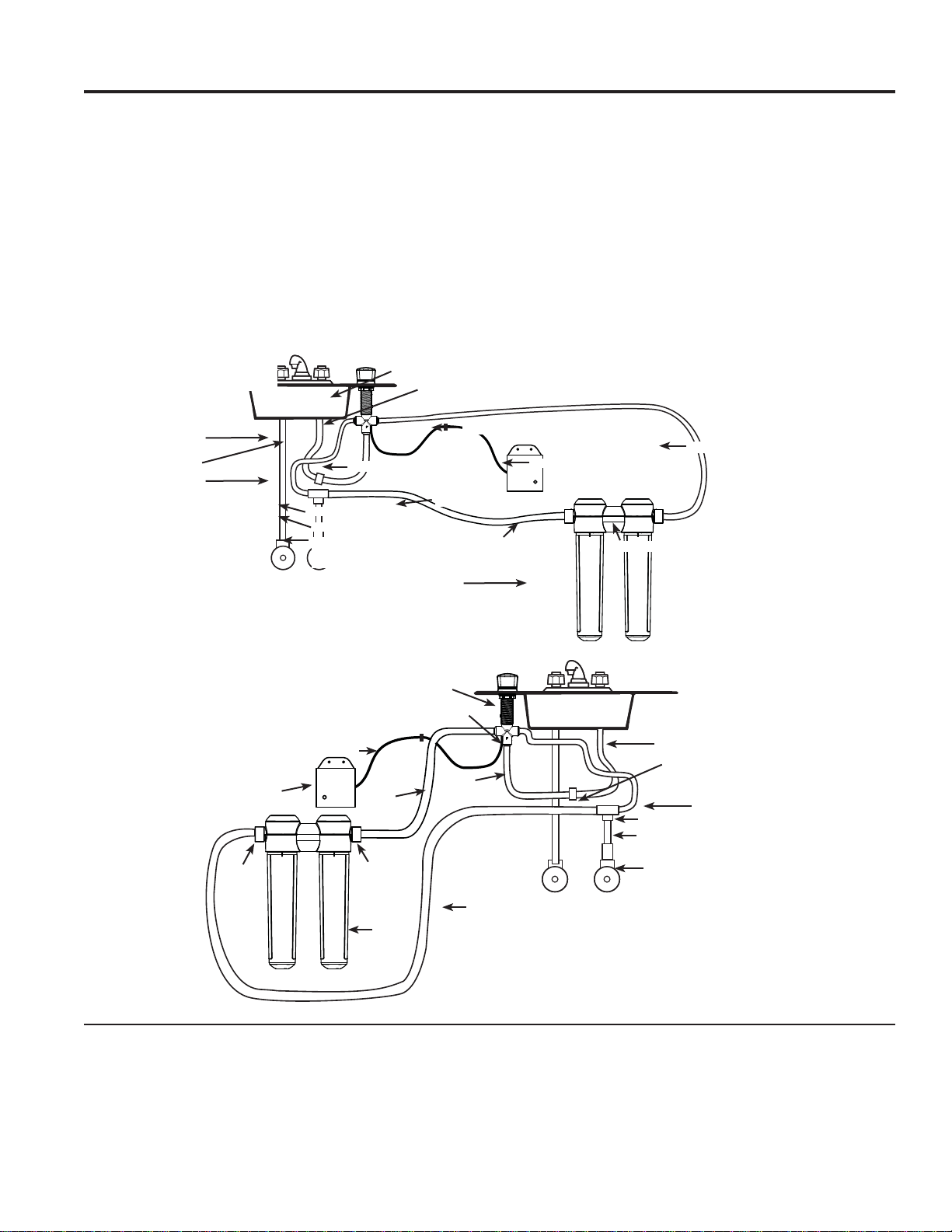
T-Fitting
Angle Stop
Valve Adapter
Filter System
Timer
Wire
Cold Water
Line Adapter
Existing Faucet
Cold Water line
3’ Yellow Tube
Yellow Tube
3’ Orange Tube
4’ Yellow Tube
4’ Blue Tube
NOTE: Make sure “F” faces toward you during installation
Control Valve
NOTE: Make sure “F” faces toward you during installation
Wire
Timer
3’ Yellow Tube
Yellow Tube
4’ Yellow Tube
Filter
System
Cold Water
Line Adapter
Existing Faucet Cold
Water line
T-Fitting
Angle Stop
Valve Adapter
3’ Orange
Tube
Outlet
Inlet
Outlet
Inlet
4’ Blue
Tube
Right Hand Installation:
Left Hand Installation:
49-50326 5
INSTALLATION INSTRUCTIONS
Installation
Kitchen Faucet Filtration System
Instructions
GXK285JBL
WARNING
—
Read “Important Safety
Information” on page 2 before beginning
installation.
TOOLS AND MATERIALS
REQUIRED FOR INSTALLATION
• Phillips screwdriver
• Two (2) adjustable wrenches
• Electric drill and drill bit to drill 1.25” hole (type as
required) if mounting hole is needed for control valve
• Tape measure
•
If your main water line is a rigid pipe, you will require
a compression fitting and possibly other plumbing
hardware to complete the installation (sold separately).
NOTICE —
To avoid damaging the sink or counter
top, consult a qualified plumber or installer for drilling
procedures. Special drill bits may be needed for granite,
stone, porcelain or stainless steel.
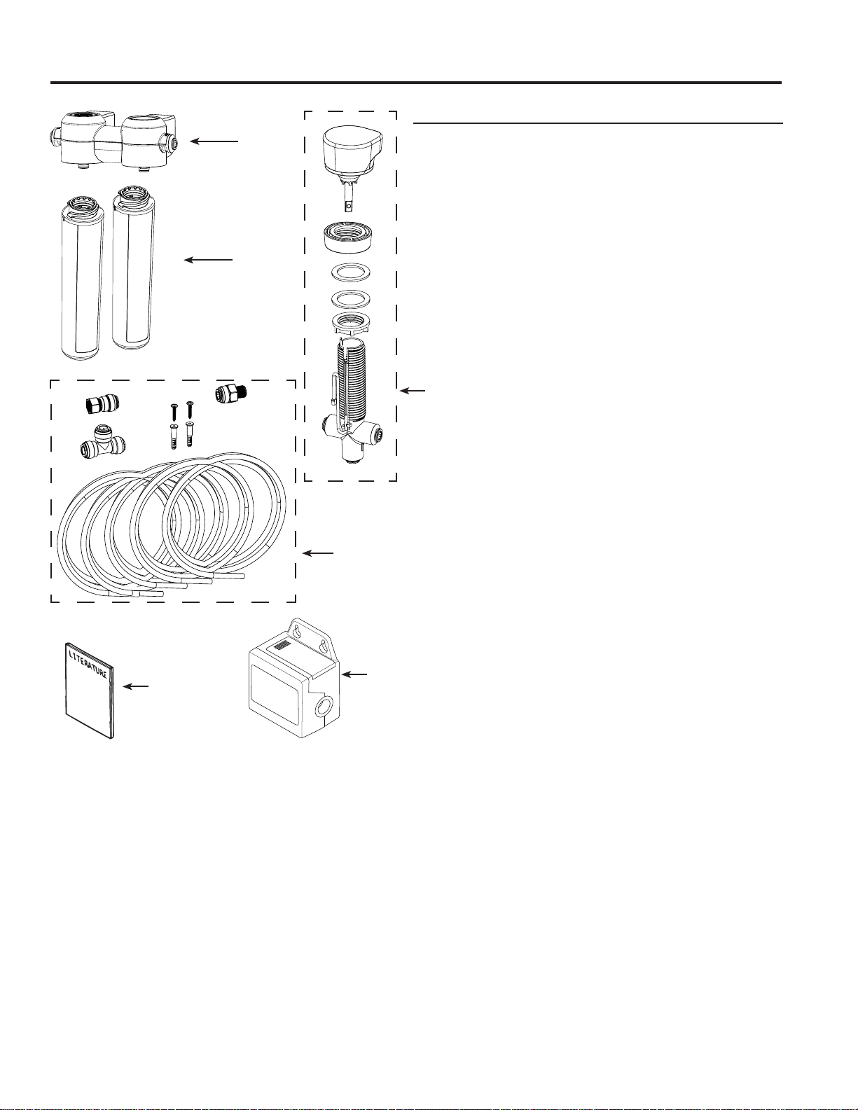
CONTENTS INCLUDED
WITH THE PRODUCT
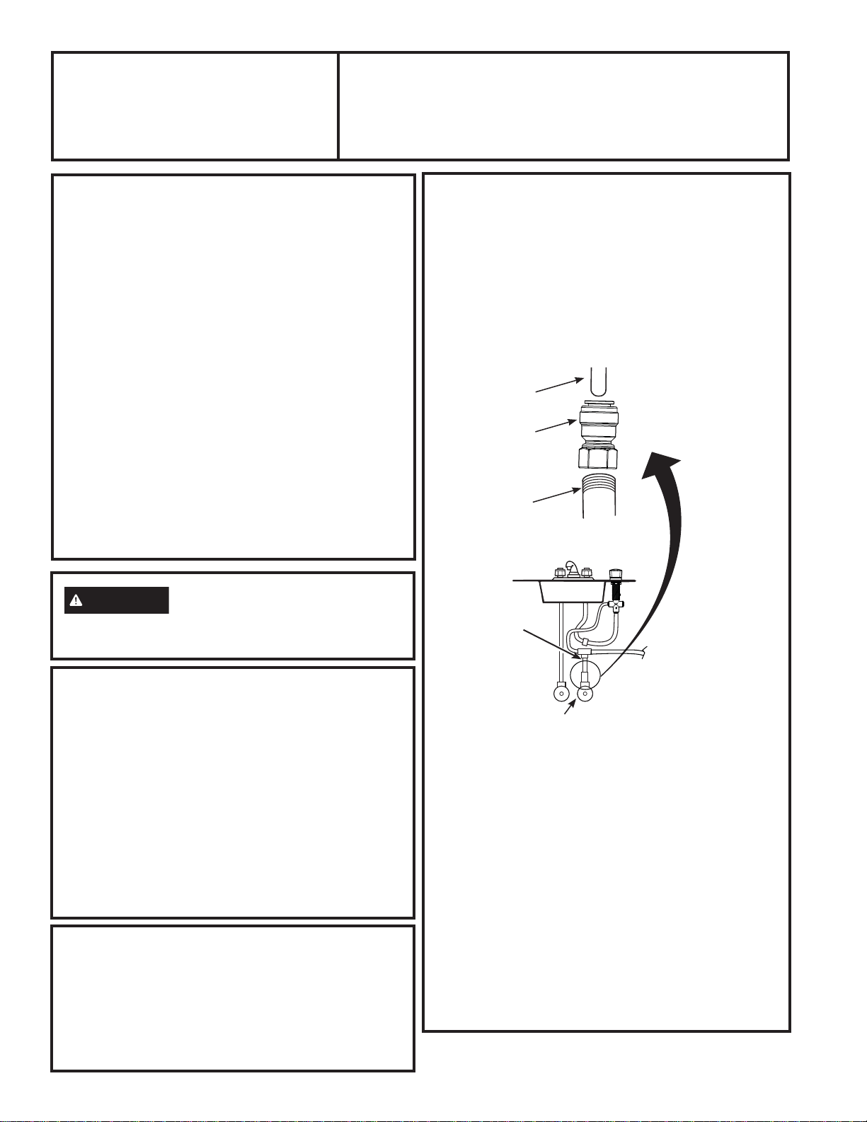
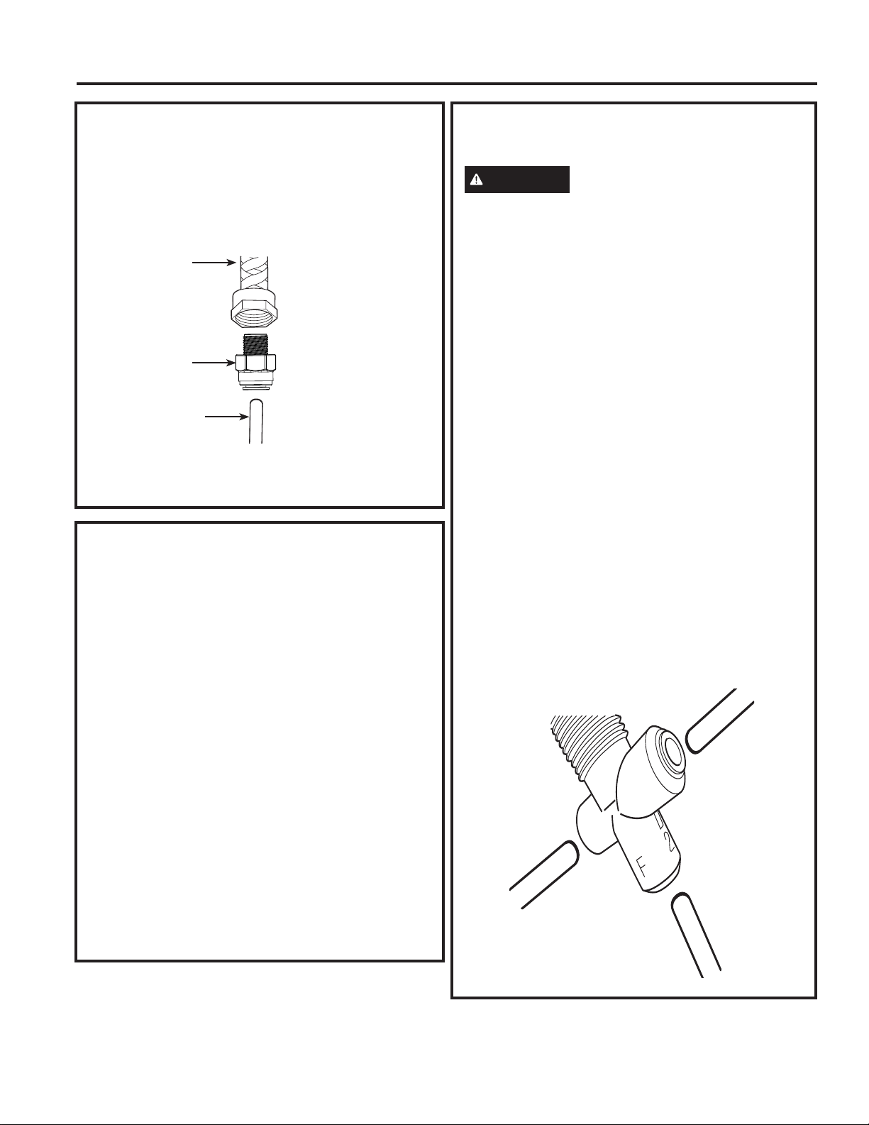
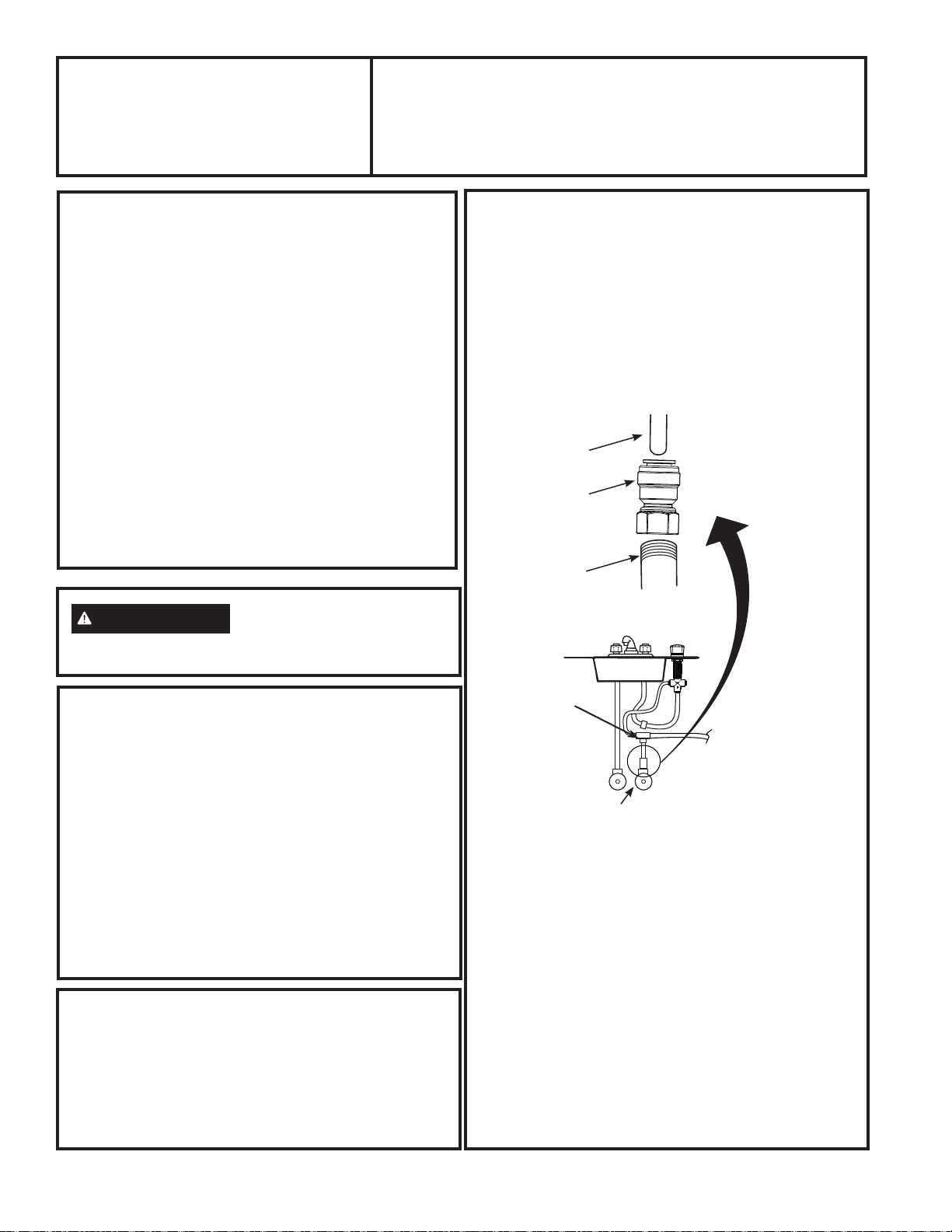
COLD WATER CONNECTION
A typical connection using the included water supply
fitting is shown in the illustration below.
1. Close the water shut-off valve that is immediately
in front of the supply tube and open the faucets to
drain water from the sink cold water pipe.
2. Remove line that connects the cold water from faucet
line to the supply valve. Some water may spill out.
3. Hand tighten the angle stop valve adapter onto
the cold water valve. NOTE: A minimum of
approximately 8 threads is required on valve
stem. Finish tightening 1/2 turn with adjustable
wrench. Be careful not to overtighten or cross-thread
as damage to threads can occur.
Some valve threads may be exposed when adapter is
fully seated.
4. Insert one foot long yellow tube fully into angle stop
valve adapter. Pull firmly on tube to make sure it is
secure.
5. Insert one foot long yellow tube into bottom of T-fitting
(see Figure 1). Insert 3 foot long yellow tube into one
side of T-fitting. Insert 4 foot long yellow tube into
other side of T-fitting. Pull firmly on tubes to make
sure they are secure.
1 foot Yellow
3/8” Tube
Cold Water Shutoff
Fig. 1
Angle Stop
Valve Adapter
Existing Cold
Water Valve
(Approximately 8
threads minimum)
T-Fitting
BEFORE YOU BEGIN
Read these instructions completely and
carefully.
•
IMPORTANT – Save these
instructions for local inspector’s use.
•
IMPORTANT – Check with your
local public works department for plumbing
codes. You must follow their guides as you
install the Water Filtration system.
• Note to Installer – Be sure to leave these
instructions with the Consumer.
• Note to Consumer – Keep these
instructions for future reference.
• Skill level – Installation of this appliance requires
basic mechanical and electrical skills.
• Completion time – 60-90 minutes
• Proper installation is the responsibility of the
installer.
• Product failure due to improper installation is not
covered under the Warranty.
• Water filter system
assembly, including
mounting screws
• Water line adapters
and tubing
• Control Valve with LED
Lights
• Decorative Knob and Nut
• Timer Box
• Batteries
6 49-50326
Installation Instructions
INSTALLATION INSTRUCTIONS
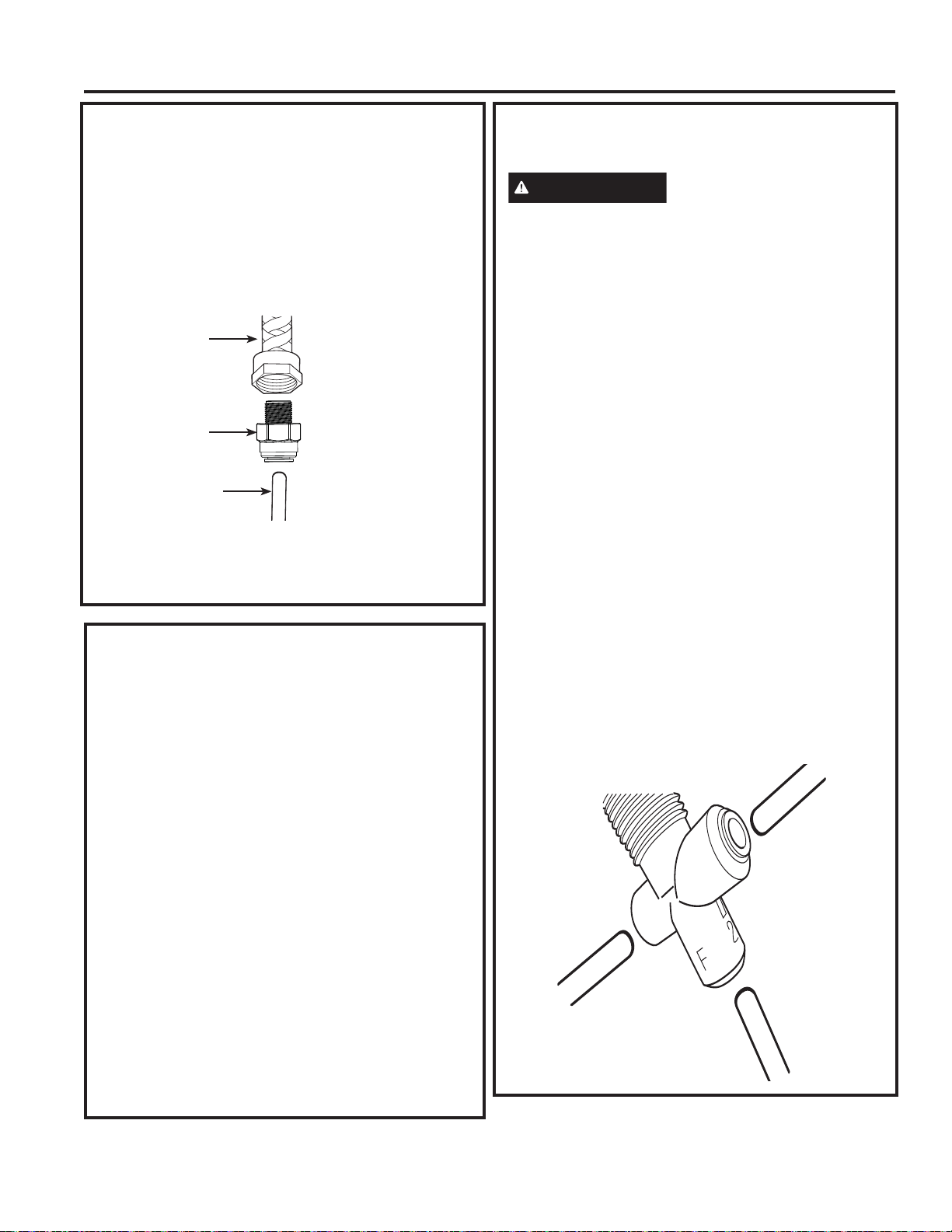
COLD WATER CONNECTION (cont.)
6. Hand tighten the cold water line adapter into the cold
water line from the faucet.
Finish tightening with two adjustable wrenches. Be
careful not to overtighten or cross thread as damage
to threads can occur. Some threads may be exposed
when adapter is fully seated.
7. Insert 3 foot orange tubing fully into cold water line
adapter. Pull firmly on tube to make sure it is secure.
INSTALL THE CONTROL VALVE
(cont.)
CAUTION
When drilling in Stainless Steel,
edges may be sharp and could damage wire. Be
careful to not cut yourself or damage the wire.
2. To have filtered water dispensed from kitchen
faucet when control valve is pointed toward faucet
connect tubes as follows:
NOTE: Refer to diagram on page 3 for tube
routing.
IF CONTROL VALVE IS ON RIGHT SIDE OF
FAUCET:
- Connect 4 foot long blue tube to port number “2”.
- Connect 3 foot long yellow tube from T-fitting to
port number “1”.
- Connect 3 foot long orange tube to port “F”
(bottom port)
Pull firmly on all tubes to make sure they are
secure.
IF CONTROL VALVE IS ON LEFT SIDE OF
FAUCET:
- Connect 4 foot long blue tube to port number “1”.
- Connect 3 foot long yellow tube from T-fitting to
port number “2”.
- Connect 3 foot long orange tube to port “F”
(bottom port)
Pull firmly on all tubes to make sure they are
secure.
Existing Cold
Water Line
from Kitchen
Faucet
Fig. 2
Cold Water
Line Adapter
3 foot Orange
Tubing
INSTALL THE CONTROL VALVE
Be sure there is room underneath and above the sink
to make the needed connections. Before starting,
make sure there is sufficient room for the valve base.
Select one of the following places to install the valve
(1.25” diameter hole required):
A. In an existing sink spray attachment or soap
dispenser hole.
B. In a hole to be drilled in the sink top.
C. In a hole to be drilled in the counter top, next to the
sink.
NOTES:
• Be sure the valve base will fit flat against the
surface at the selected location.
Installation Steps (refer to illustration below for
clarification)
1. ,IGULOOLQJLVQHHGHGPDNHDƎGLDPHWHUKROH
Be sure to use the proper procedure for drilling
granite, stone, porcelain or stainless steel.
Special drill bits may be needed. Consult a
qualified plumber for the proper procedure.
Blue or Yellow
Tube (see above)
Blue or Yellow
Tube (see above)
Orange Tube
49-50326 7
Installation Instructions
INSTALLATION INSTRUCTIONS
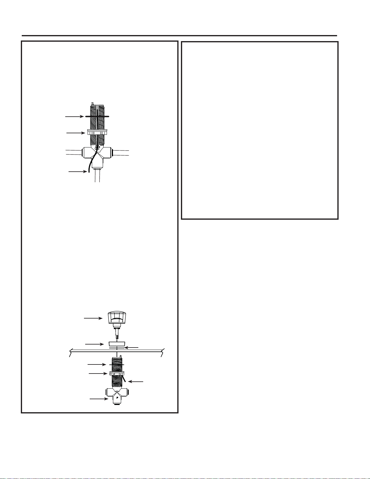
INSTALL THE CONTROL VALVE
(cont.)
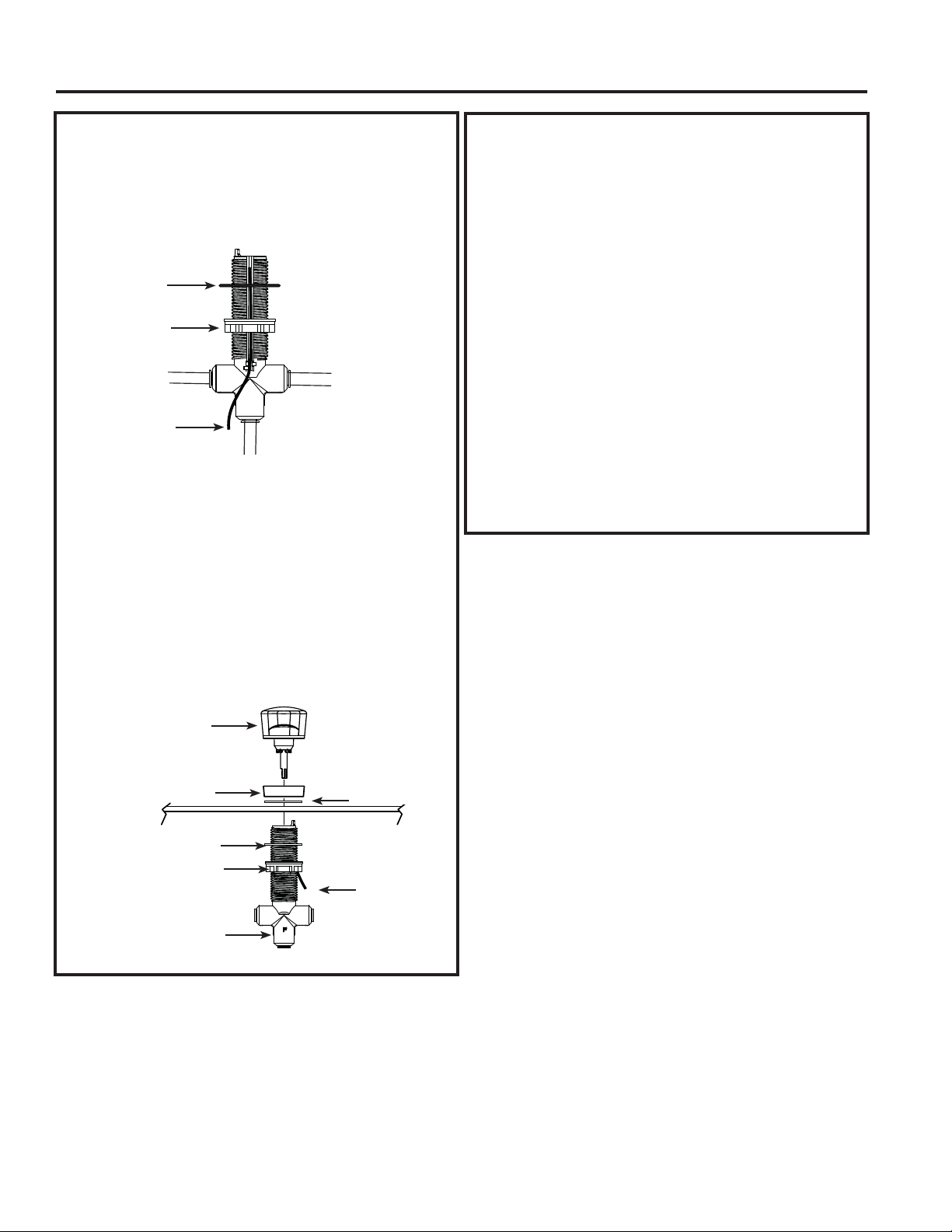
3. With wire routed under rubber gasket and locking
nut (as shown below) thread nut at least 3/4 toward
bottom.
4. With “F” port label facing toward you (wire groove
facing back of cabinet) insert control valve up
through hole in sink/counter top.
5. Install 2nd rubber gasket on the control valve.
Insert decorative nut on top of control valve turning
fully until it stops, approximately two turns of nut.
Do not overtighten.
6. Turn locking nut clockwise to tighten until it is firmly
secure against underside of sink/counter top. Do
not allow control valve body to rotate, “F” port label
should face toward you after locking nut is tight.
Rubber Gasket
Locking Nut
Wire
INSTALL THE CONTROL VALVE
(cont.)
7. Insert control knob into valve body.
NOTE: Knob only inserts in one position,
rotate slowly until you feel it drop slightly into
place. Then push down firmly to snap in place.
8. Check knob rotation. Knob should rotate 180
degrees and point towards you as it rotates left/
right. If point of knob rotates towards wall, then
unit is installed backwards. Please review step 2.
9. Connect wire to timer box.
10. Find suitable location for timer box and battery
access. Mount timer box to side of wall or cabinet
with two screws (and drywall anchor) provided.
NOTE: Be careful not to pinch or screw
through the wire.
11.Install two AA, 1.5 volt, batteries into timer box.
Control Knob
Decorative Nut
Wire
Rubber Gasket
Locking Nut
NOTE:
“F” facing toward you.
Rubber Gasket
8 49-50326
Installation Instructions
INSTALLATION INSTRUCTIONS
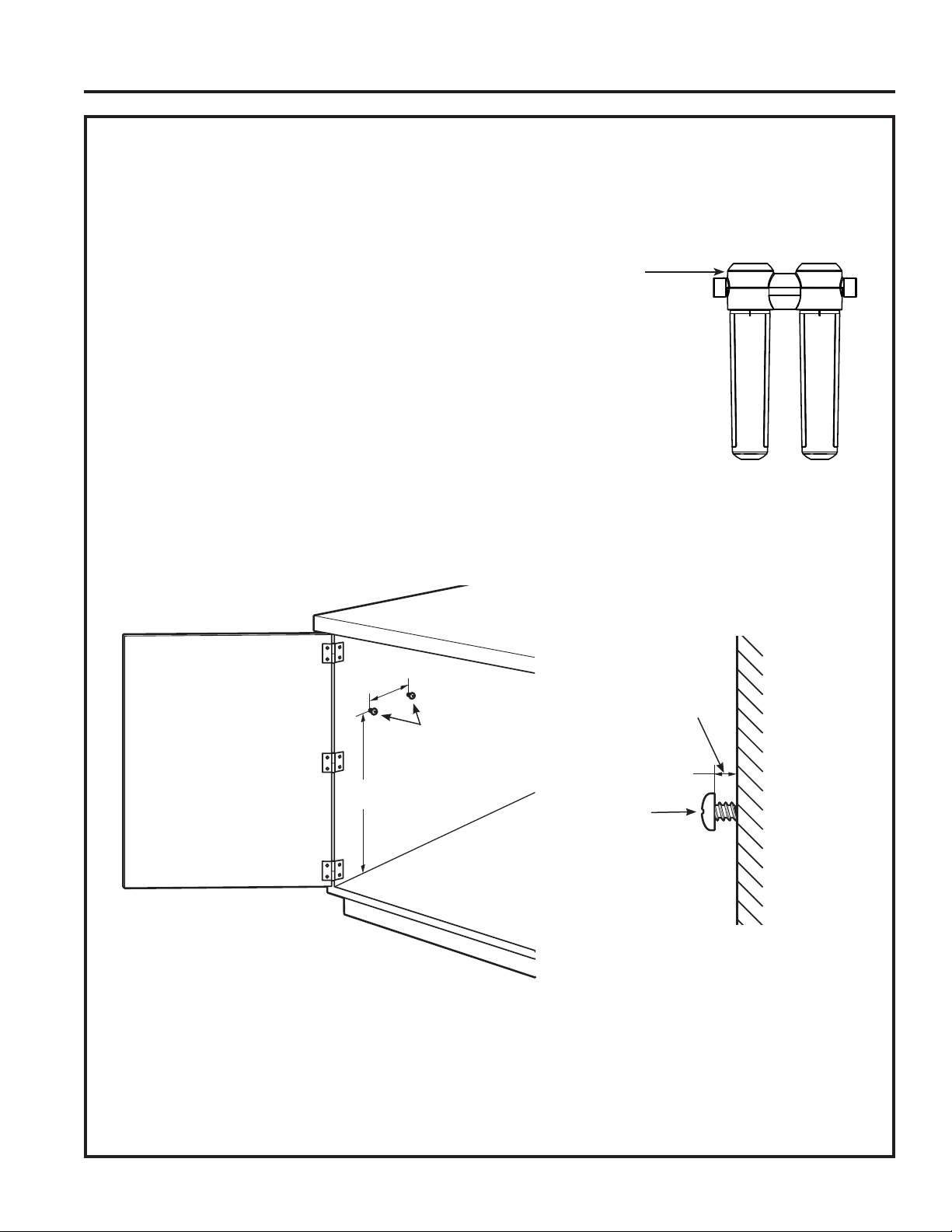
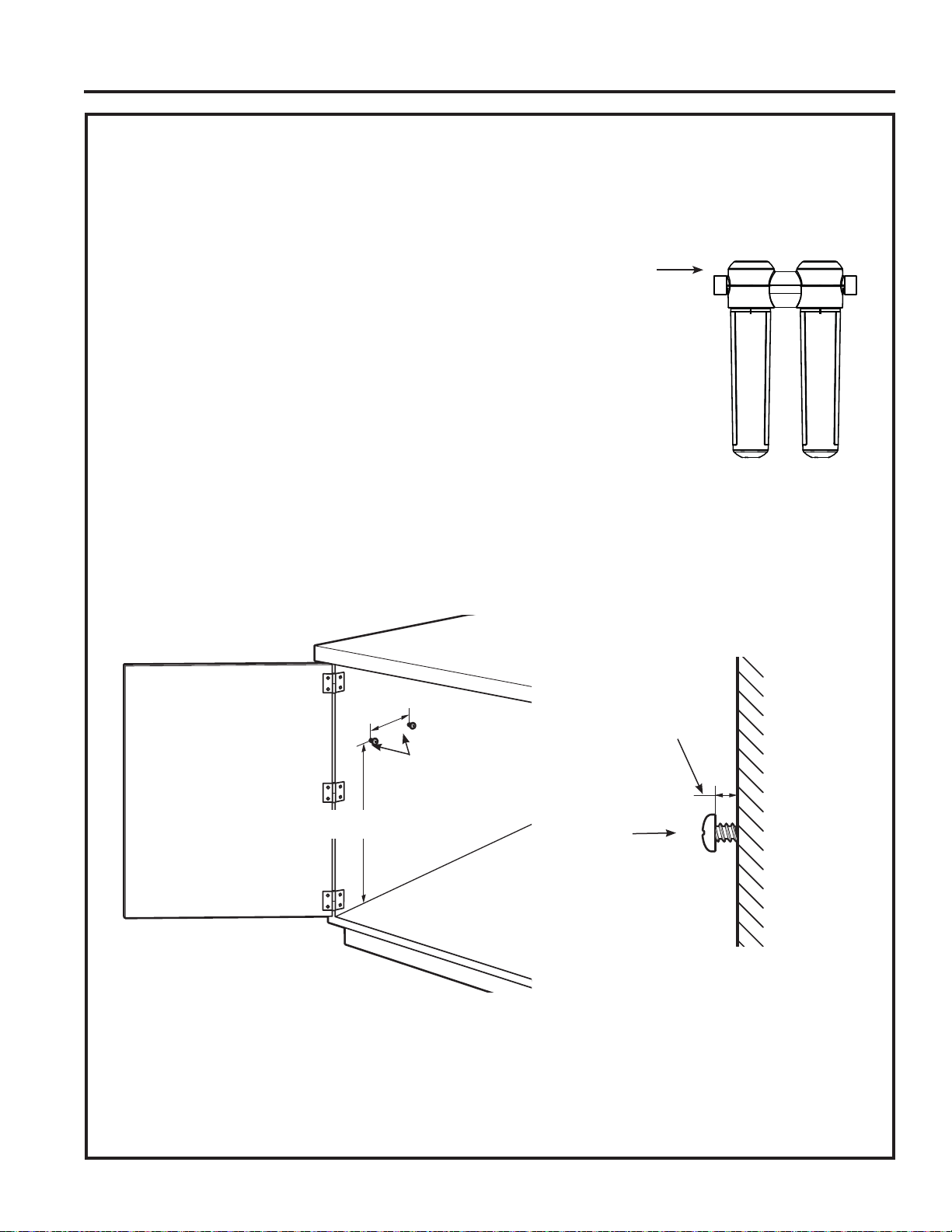
MOUNTING SYSTEM INSTALLATION
Pick a location under the sink to mount the system. Location should be easily accessible, with 4” of clearance
between the bottom of the filter canisters and the floor or bottom of the cabinet; any less will result in difficulty
of removing filter canisters (see Fig. 5). Allow enough space on either side of the system for the tubing
connections. System should be mounted at least 7” from front of cabinet to allow proper routing of tubing.
SCREW INSTALLATION
1. Remove the top cover of system.
2. Screws should be placed a minimum of 15 inches above the
bottom of the cabinet or floor where the system is to be mounted
(Fig. 5).
NOTE: Any distance lower may result in filter canisters
interfering with the floor when removed.
3. Use the system as a template to mark screw hole locations where
the screws are to be installed. Install screws into the wall, leaving
3/16 inch clearance between the head of the screw and wall (drill
pilot holes if needed) (Fig. 6). Use anchors if mounting to drywall.
Anchors require a 1/4” hole.
4. Hang system on screws and tighten until system is held firmly.
5. Install top cover onto system.
6. Install 4 foot long yellow tube into inlet (left side) of system (inlet and outlet are labeled on top of the system).
7. Install 4 foot long blue tube into outlet (right side) of system. Pull firmly on tubes to make sure they are
secure.
8. Remove shrink wrap from filters and install in system by turning approximately 1/3 turn until locked into place.
Filter will raise up as it is turned. Filter label will be centered and facing forward when fully installed.
NOTE: System may exhibit low flow or no flow at all if the filter is not fully installed.
9. Turn on water supply valve and check for leaks.
10. Perform Flush Procedure as described on page 9, steps 3-7.
15 inches
Screws
Screw
3/16 inch
Fig. 6
Fig. 5
Wall
System
Top Cover
49-50326 9
Installation Instructions
INSTALLATION INSTRUCTIONS
FILTER CHANGE LIGHT
The clear ring at the bottom of the control knob will
flash red to indicate it is time to change the filter and
the battery.
The ring will double flash at six months to indicate it is
time to replace the filter.
The ring will have a single fading flash at one year
to indicate it is time to replace the filters and the
batteries.
INSTALLING OR REPLACING THE
FILTER CANISTERS
TO PROPERLY MAINTAIN SYSTEM AND
REDUCE THE RISK OF PROPERTY DAMAGE
DUE TO WATER LEAKAGE, CHANGING
FILTER AS REQUIRED.
If installing the system for the first time skip to step 3.
1. Remove the filter canisters from the manifold by
rotating the canisters to the left about 1/3 turn.
NOTE: A small amount of water from the tubing
between the filter and the faucet may come out. A
small towel should be able to catch it.
2. Remove shrink wrap on the new replacement
filter canisters. Install the new canisters into the
manifold by turning to the right about 1/3 turn until
the filter stops. The filter will rise up as it is turned.
FLUSH PROCEDURE
3. Turn on cold side of kitchen faucet. Turn control
valve so it is pointing towards kitchen faucet (water
will flow slower when passing through filters).
NOTE: System may make noise during this
procedure.
4. Check for water leaks around the system.
5. Allow the system to run for 11 gallons (or 10
minutes) to flush out any harmless carbon fines
that may be present.
6. Turn off faucet and check around system for leaks.
7. Reset timer by holding reset button on timer box
for 5 seconds. Ring in base of control valve will
light for 5 seconds. If single fading flash was
occurring, replace batteries before resetting the
timer.
Replacement Filter Canisters/
Estimated Replacement Costs
FQK2J—Replacement filter canister $45–55
For replacement parts, call toll-free 877.959.8688
(U.S.) or 800.661.1616 (Canada–English).
EMERGENCY REPLACEMENT
PROCEDURE
Whenever water of unknown quality is passed
through the GE Water Filtration system, the filter
canisters should be discarded and the filtration
system flushed.
WARNING
To reduce risk of ingestion
of contaminants, do not use with water that is
microbiologically unsafe or of unknown quality without
adequate disinfection before or after the system.
Circumstances that may require replacing the
filters are:
• Boil water advisory
• Flooding of the GE Water Filtration system
• Long-term non-use
The procedure for flushing the GE Water Filtration
system is:
1. See Replacing the Filter Canisters section and
follow steps 1–7.

10 49-50326
Troubleshooting Tips... Before you call for service
TROUBLESHOOTING TIPS
Save time and money! Review the charts on the following pages first and you may not need to call for service.
Problem Possible Causes What To Do
Water contains tiny black particles New filter canisters contain
activated carbon.
• Turn on the filtered water faucet and allow to run for 11
gallons (or 10 minutes) to flush out any harmless carbon fines
that may be present.
Water has air bubbles and is
cloudy
Air in system after
installation.
• Will go away after water runs for a while.
Indicator light on the control valve
is flashing
Six months usage has
occurred. This is the
maximum life of the filter
canisters.
• If double flash, replace filters.
• If single fading flash, replace filters and batteries.
Indicator light on the control valve
is not blinking
Normal operation. • Does not blink until 6 months of operation has passed.
• Normally the light is not on. The light blinks every 20 seconds
to indicate a filter change is needed. This occurs about every
6 months.
Battery may need to be
replaced.
•
Replace battery and press reset button for 5 seconds.
Indicator will light to indicate proper installation and operation.
Timer is reset for 6 months.
Indicator light on the control valve
is not working
when new battery is
installed
Battery may have been
installed incorrectly or wire
not connected.
• Observe battery orientation markings on the holder.
• Ensure wire is connected from control valve to timer box.
•
Press reset button for 5 seconds to reset timer, indicator will
light and timer is reset for 6 months..
Chlorine taste and odor in the
product water
The filter canisters are no
longer reducing chlorine
taste and odor from the
water supply.
•
Replace the filter canisters.
Water dispenses
very slowly
The filters have been
installed for too long.
• A six-month change-out period is recommended. Replace
both filter canisters.
The filter canisters have
become clogged.
• High sediment levels can cause premature clogging.
Replace both filter canisters.
Filter not installed fully •
Ensure filter is fully installed, label should be centered and
facing forward.
Fittings are leaking Tubing may not be installed
properly.
• Fully follow the installation instructions and be sure the tubing
is free of nicks, burrs, etc., and is installed to the proper depth.
No water dispensing
from system
Filter canisters not fully
installed.
• Fully follow the filter replacement instructions.
If you are still having trouble, please call us at 800.626.2005 in the USA or 877.994.5366 in Canada.
49-50326 11
Parts List
PARTS LIST
004
005
001
002
999
003
Ref. No. Part No. Part Description
001 WS22X21084 Install Kit 1
002 WS15X21085 Timer 1
003 WS10X21083 Control Valve Assembly (Chrome) 1
004 WS19X21082 Filtration Manifold 1
005 FQK2J Filter Set 1
999 49-50306 Owner’s Manual 1
To obtain replacement parts, call toll-free 877.959.8688 (U.S.),
800.661.1616 (Canada–English).
12 49-50326
WARRANTY
GE Appliances Water Filtration Warranty
LIMITED ONE-YEAR WARRANTY
• What does this warranty cover?
— Any defect in materials or workmanship in the
manufactured product.
• What does this warranty not cover?
— Filter canisters and batteries after 30 days from
date of purchase.
— Service trips to your home to teach you how to use
the product.
— Improper installation, delivery or maintenance.
— Failure of the product if it is abused, misused,
altered, used commercially or used for other than
the intended purpose.
— Use of this product where water is microbiologically
unsafe or of unknown quality, without adequate
disinfection before or after the system.
— Damage to the product caused by accident, fire,
floods or acts of God.
— Incidental or consequential damage caused
by possible defects with this appliance, its
installation or repair.
• For how long after the original purchase?
— One (1) year.
• How do I make a warranty claim?
— Return to the retailer from which it was purchased,
along with a copy of the “Proof of Purchase.” A
new or reconditioned unit will be provided. This
warranty excludes the cost of shipping or service
calls to your home.
This warranty is extended to the original purchaser
and any succeeding owner for products purchased
for home or office use within the USA. In Alaska, the
warranty excludes the cost of shipping or service to
your home or office.
Some states do not allow the exclusion or limitation
of incidental or consequential damages. This
warranty gives you specific legal rights, and you
may also have other rights, which vary from state
to state. To know what your legal rights are, consult
your local or state consumer affairs office or your
state’s Attorney General.
Contact GE Appliances at www.GEAppliances.com/
ge/service-and-support/contact.htm, or call toll-free
at 800.626.2005.
EXCLUSION OF IMPLIED WARRANTIES—Your
sole and exclusive remedy is product exchange
as provided in this Limited Warranty. Any implied
warranties, including the implied warranties of
merchantability or fitness for a particular purpose,
are limited to one year or the shortest period
allowed by law.
For Purchases Made In Iowa: This form must be signed and dated by the buyer and seller prior to the consummation
of this sale.
This form should be retained on file by the seller for a minimum of two years.
Seller:
Name
Address
City State Zip
Signature Date
Buyer:
Name
Address
City State Zip
Signature Date

49-50326 13
NOTES
Notes

14 49-50326
Printed in Taiwan
Consumer Support
CONSUMER SUPPORT
GE Appliances Website
Have a question or need assistance with your appliance? Try the GE Appliances Website 24 hours a day, any day
of the year! You can also shop for more great GE Appliances products and take advantage of all our on-line support
services designed for your convenience. In the US: GEAppliances.com
Parts and Accessories
Individuals qualified to service their own appliances can have parts or accessories sent directly to their homes
(VISA, MasterCard and Discover cards are accepted). Order on-line today 24 hours every day.
In the US: GEApplianceparts.com or by phone at 877.959.8688 during normal business hours.
Instructions contained in this manual cover procedures to be performed by any user. Other servicing
generally should be referred to qualified service personnel. Caution must be exercised, since improper
servicing may cause unsafe operation.
Contact Us
If you are not satisfied with the service you receive from GE Appliances, contact us on our Website with all the
details including your phone number, or write to:
In the US: General Manager, Customer Relations | GE Appliances, Appliance Park | Louisville, KY 40225
GEAppliances.com/ge/service-and-support/contact.htm
ESPAÑOL
MANUAL DEL
PROPIETARIO E
INSTALACIÓN
49-50318 10-16 GEA
INFORMACIÓN
DE SEGURIDAD .............. 2
GENERALIDADES
DEL SISTEMA ................ 3
INSTRUCCIONES
DE INSTALACIÓN ............ 5
Suministro del agua .................4
Instale la válvula de control .......... 5
Instalación del sistema de montaje .... 7
Cambio del filtro de luz .............. 8
Reposición del filtro ................. 8
Procedimiento para lavar ............ 8
CONSEJOS PARA LA SOLUCIÓN
DE PROBLEMAS .............9
SOPORTE AL
CONSUMIDOR ...............12
GE es una marca registrada de General Electric Company. Fabricado bajo licencia de marca.
SISTEMA DE FILTRADO
DE AGUA
El Sistema GXK285JBL está
certificado por IAPMO R&T contra
los Estándares 42,53, y 401 de NSF/
ANSI para la reducción de reclamos
especificados en la ficha técnica de
rendimiento y en aipmort.org.
GXK285JBL
PLATINUM SEAL
WATER QUALITY
I
A
P
M
O
R
E
S
E
A
R
C
H
A
N
D
T
E
S
T
I
N
G
™

2 49-50326
GRACIAS POR HACER QUE LOS ELECTRODOMÉSTICOS
GE SEAN PARTE DE SU HOGAR.
Ya sea que haya crecido usando Electrodomésticos GE, o que ésta es su primera vez,
nos complace tenerlo en la familia.
Sentimos orgullo por el nivel de arte, innovación y diseño de cada uno de los Electrodomésticos GE,
y creemos que usted también.
49-50326 3
INFORMACIÓN DE SEGURIDAD
INFORMACIÓN IMPORTANTE DE SEGURIDAD
LEA TODAS LAS INSTRUCCIONES ANTES DE USAR
INSTRUCCIONES IMPORTANTES DE SEGURIDAD
A fin de reducir el riesgo de incendio, explosión, descargas eléctricas
o lesiones al usar su refrigerador, siga estas precauciones básicas de
seguridad:
A fin de reducir el riesgo de lesiones al usar el refrigerador, siga estas
precauciones básicas.
A fin de reducir el riesgo asociado con descargas, no
permita que los niños menores de tres años tengan acceso
a las partes pequeñas durante la instalación de este
producto.
A fin de reducir el riesgo asociado con la ingestión de
contaminantes, no use con agua que no sea segura a
nivel microbacteriológico o de calidad desconocida, sin una
desinfección adecuada, antes o después, del sistema.
A fin de reducir el riesgo asociado con el peligro de voltaje
debido a una perforación durante una instalación a través
de un cableado eléctrico existente o tubería de agua en
el área de la instalación, no instale cerca de cableados
eléctricos ni tuberías que se puedan interponer con una
herramienta de perforación al seleccionar la posición para
montar el soporte del sistema..
Si este dispositivo no es mantenido y operado de acuerdo
con lo especificado en el manual del propietario, existe
el riesgo de exposición a contaminantes. Para más
información, visite el sitio Web del fabricante en www.
geappliances.com o el sitio Web de California State
Water Resources Control Board (Junta de Control de los
Recursos del Agua del Estado
de California) en www.
waterboards.ca.gov.
ADVERTIR:
Lea y siga las Instrucciones de Uso antes de la instalación
y uso de este sistema.
La instalación y uso DEBERÁN cumplir con todos los
códigos de plomería estatales y locales.
No use en un suministro de agua caliente (máximo de
100°F). Instale en un suministro de agua fría únicamente.
No instale en líneas de suministro de agua caliente. La
temperatura máxima de funcionamiento del agua para este
sistema de filtro es de 100°F (37.8°C).
No se deberá instalar si la presión del agua supera los
125psi (8.8 Kg/cm
2
). Si la presión del agua es superior
a los 80 psi (5.6 Kg/cm
2
), deberá instalar una válvula
limitadora de presión. Si no está seguro sobre cómo
controlar la presión del agua, comuníquese con un plomero
profesional.
No instale sistemas en áreas donde la temperatura
ambiente pueda ser superior a 110° F (43.3° C).
El cartucho del filtro descartable debería ser reemplazado
cada 6 meses, una vez agotada la capacidad indicada o
antes si se produce una reducción notoria en el caudal.
Cuando haya instalado un dispositivo anti retorno en el
sistema de agua, se deberá instalar un dispositivo para
controlar la presión debido a la expansión termal.
No instale cuando se puedan producir condiciones de
golpe de ariete. Si existen condiciones de golpe de
ariete, deberá instalar un suspensor de golpes de ariete.
Si no está seguro sobre cómo controlar esta condición,
comuníquese con un plomero profesional.
Esegúrese de que toda la tubería y los accesorios estén
seguros y libres de pérdidas.
Sobre los accesorios de plástico, nunca use sellador para
tuberías ni pegamento para tuberías. Use sólo cinta para
roscas PTFE, ya que el pegamento para tuberías podría
deteriorar el plástico.
No use una antorcha u otras fuentes de alta temperatura
cerca del sistema, del cartucho, de los accesorios de
plástico o tuberías de plástico.
No instale en contacto directo con la luz del sol ni en áreas
exteriores..
No instale cerca de tuberías de agua que puedan
interponerse en el camino de una herramienta para
perforar, al seleccionar la posición para montar el soporte.
Monte el sistema en una posición donde se pueda evitar
que quede atascado por otros artículos usados en el área
de la instalación.
Asegúrese de que la ubicación y los sujetadores puedan
resistir el peso del sistema cuando esté instalado y lleno
de agua
LEA Y GUARDE ESTAS INSTRUCCIONES
PRECAUCIÓN
A fin de reducir el riesgo de lesión física, despresurice el sistema como se muestra en el manual antes de retirar un
cartucho.
ADVERTENCIA
4 49-50326
Cómo funciona.
VISIÓN GENERAL DEL SISTEMA: Cómo funciona.
Este sistema le permite elegir entre agua filtrada y no
filtrada del grifo actual de su cocina. El sistema consta de
una válvula de control, un temporizador y filtros. La tubería
de agua existente está dividida en dos tuberías. Una pasa a
través del sistema de filtrado hasta la válvula de control. La
otra tubería se conecta directamente a la válvula de control.
Cuando la válvula de control está apuntando hacia fuera del
grifo de su cocina, se dispensa agua normal no filtrada.
Cuando la válvula de control está apuntando hacia el grifo de
su cocina, se dispensa agua filtrada.
Observará un flujo de agua levemente inferior cuando se esté
dispensando agua filtrada.
La base de la válvula de control titilará en rojo cuando sea
el momento de cambiar los filtros y baterías. Cuando la luz
que titila es doble, significa que pasaron 6 meses y que es
necesario reemplazar los filtros. Cuando titila sólo una vez y la
luz se desvanece, significa que pasó 1 año y que es necesario
reemplazar los filtros y las baterías del temporizador.
Pautas de las especificaciones
Se pueden reducir muchos malos olores y/o sabores del
agua usando cartuchos de carbono para el filtro. Se usan
principalmente para reducir el olor y sabor a cloro. También
pueden reducir otros elementos no deseados del suministro
de agua.
NOTA: Se pueden reducir por poco tiempo pequeñas
cantidades de sulfuro de hidrógeno como el olor a “huevo
podrido” usando filtros de olor y sabor, pero el medio de
carbono se agota rápidamente. Por lo general, se requieren
otros equipos acondicionadores de agua para el tratamiento
continuo del sulfuro de hidrógeno.
Conector T
Adaptador
para Válvula
de Detención
en Ángulo
Sistema
de Filtrado
Temporizador
Válvula de Control
Adaptador de la
Tubería de Agua Fría
Tubería de Agua
Fría del Grifo Actual
Tubería Amarilla de 3’
Tubería Amarilla
Tubería
Anaranjada de 3’
Tubería
Amarilla de 4’
Tubería Azul de 4’
NOTA: Asegúrese de que “F” mire hacia usted durante la instalación.
Válvula de Control
NOTA: Asegúrese de que “F” mire hacia usted durante la instalación.
Cable
Temporizador
Tubería Amarilla de 3’
Tubería Amarilla
Tubería
Amarilla
de 4’
Sistema
de
Filtrado
Tubería Azul de 4’
Adaptador de la
Tubería de Agua Fría
Tubería de Agua Fría
del Grifo Actual
Conector T
Adaptador para
Válvula de
Detención en Ángulo
Tubería
Anaranjada
de 3’
Cable
Outlet
Inlet
Outlet
Inlet
Instalación del Lado Derecho:
Instalación del Lado Izquierdo::
49-50326 5
INSTRUCCIONES DE INSTALACIÓN
Instrucciones
Sistema de Filtrado del Grifo de la Cocina
de instalación
GXK285JBL
ACCESORIO PARA EL
SUMINISTRO DE AGUA FRÍA
En la ilustración que aparece a continuación
se muestra una conexión típica usando el accesorio para el
suministro de agua incluido.
1. Cierre la válvula de agua que se encuentra
inmediatamente en frente del tubo de suministro y
abra los grifos para dejar correr el agua de
la tubería de agua fría del lavaplatos.
2.
Retire la entrada que conecta el agua fría desde la
tubería de agua a la válvula de suministro. Es posible
que se derrame un poco de agua.
3. Ajuste manualmente el adaptador de la válvula de
detención en ángulo sobre la válvula de agua fría.
NOTA: Se requiere un mínimo de 8 roscas en el
vástago de la válvula. Termine de ajustar dando ½
giro con una llave de ajuste. Asegúrese de no forzar ni
presionar por demás a fin de evitar dañar la rosca.
Es posible que las roscas de algunas válvulas queden
expuestas cuando el adaptador esté completamente
colocado.
4. Inserte la tubería amarilla de un pie completamente en
el adaptador de la válvula de detención. Empuje hacia
usted de manera firme para controlar que esté segura.
5. Inserte la tubería amarilla de un pie de longitud en la
parte inferior del conector T (vea la Figura 1). Inserte
una tubería amarilla de 3 pies de longitud sobre un lado
de la tubería T. Inserte una tubería amarilla de 4 pies de
longitud sobre el otro lado de la tubería T. Empuje las
tuberías hacia usted de manera firme para controlar que
estén seguras.
Tubería de 3/8”
Amarilla de 1 Pie
Cierre de Agua Fría
Fig. 1
Adaptador para
Válvula de
Detención en Ángulo
Válvula de Agua
Fría Existente
(mínimo de 8
roscas en el
vástago de la
válvula)
ADVERTENCIA
—
Leer “ Información importante
de seguridad “ en la página 2 antes de comenzar la
instalación
HERRAMIENTAS Y MATERIALES
NECESARIOS PARA LA INSTALACIÓN
• Destornillador de estrella
• Dos (2) llaves ajustables
• Taladro eléctrico y broca para el taladro para perforar
XQRULILFLRGHƎGHOWLSRQHFHVDULRSDUDHOJULIRVL
necesario
• Cinta métrica
• Si su línea de agua principal es de tubería rígida, usted
necesitará un accesorio de compresión y posiblemente
alguna otra herramienta de plomería para completar la
instalación (se vende por separado).
Notice — Para evitar daños al lavaplatos o mostrador,
consulte con un plomero o instalador calificado para
los procedimientos de perforación. Podrían necesitarse
brocas especiales para
granito,
piedra, porcelana o acero
inoxidable.
CONTENIDO INCLUIDO CON
EL PRODUCTO
ANTES DE INICIAR
Lea estas instrucciones completa y
cuidadosamente.
•
IMPORTANTE – Guarde estas
instrucciones para uso del inspector local.
•
IMPORTANTE – Consulte con su
departamento local de obras públicas para los códigos
de plomería. Usted debe seguir estas pautas a medida
que instala el sistema de filtración de agua.
• Nota al instalador – Asegúrese de dejar estas
instrucciones con el consumidor.
• Nota al consumidor – Conserve estas
instrucciones para referencia futura.
• Nivel de destreza – La instalación de este aparato
requiere de destrezas mecánicas básicas.
• Tiempo de ejecución – 60-90 minutos
• La instalación apropiada es la responsabilidad del
instalador.
• La falla del producto debido a una instalación
inadecuada no está cubierta por la garantía.
•
Ensambladura del sistema
de filtración de agua,
incluyendo los tornillos de
instalación
•
Adaptadores y tuberías del
suministro de agua
• Válvula de Control con
Luces LED
• Perilla y Tuerca Decorativa
• Caja del Temporizador
• Baterías
Tubería T
6 49-50326
Instrucciones de instalación
INSTRUCCIONES DE INSTALACIÓN
ACCESORIO PARA EL
SUMINISTRO DE AGUA FRÍA
(continúa)
6.
Ajuste de forma manual el adaptador de la tubería de
agua fría en la tubería de agua fría desde el grifo.
Termine de colocar con dos llaves de ajuste. Asegúrese
de no forzar ni presionar por demás a fin de evitar
dañar la rosca. Es posible que las roscas de algunas
válvulas queden expuestas cuando el adaptador esté
completamente colocado.
7. Inserte la tubería anaranjada de 3 pies completamente
en el adaptador de la tubería de agua fría. Empuje hacia
usted de manera firme para controlar que esté segura.
INSTALE LA VÁLVULA DE CONTROL
(continúa)
PRECAUCIÓN
Al perforar sobre acero
inoxidable, es posible que los extremos sean filosos y esto
podría dañar el cable. Sea cuidadoso a fin de no sufrir un
corte ni dañar el cable.
2. A fin de contar con agua filtrada que sea dispensada
desde el grifo de la cocina cuando la válvula de
control apunte hacia el grifo, conecte las tuberías de la
siguiente manera:
NOTA: Para conocer el recorrido del tubo, consulte
el diagrama de la página 3.
SI LA VÁLVULA DE CONTROL SE ENCUENTRA DEL
LADO DERECHO DEL GRIFO:
- Conecte la tubería azul de 4 pies de longitud en el
puerto número “2”.
- Conecte la tubería amarilla de 3 pies de longitud desde
el conector T al puerto número “1”.
- Conecte la tubería anaranjada de 3 pies de longitud al
puerto “F” (puerto inferior).
Empuje todas las tuberías hacia usted de manera firme
para controlar que estén seguras.
SI LA VÁLVULA DE CONTROL SE ENCUENTRA DEL
LADO IZQUIERDO DEL GRIFO:
- Conecte la tubería azul de 4 pies de longitud en el
puerto número “1”.
- Conecte la tubería amarilla de 3 pies de longitud desde
el conector T al puerto número “2”.
- Conecte la tubería anaranjada de 3 pies de longitud al
puerto “F” (puerto inferior).
Empuje todas las tuberías hacia usted de manera firme
para controlar que estén seguras.
Tubería de
Agua Fría
Actual desde
el Grifo de la
Cocina
Fig. 2
Adaptador de la
Tubería de Agua
Fría
Tubería Anaranjada
de 3 pies
INSTALE LA VÁLVULA DE
CONTROL
Asegúrese de que haya lugar debajo y arriba del lavabo
a fin de realizar las conexiones necesarias. Antes de
comenzar, asegúrese de que haya suficiente espacio para
la base de la válvula. Seleccione uno de los siguientes
lugares para instalar la válvula (se requiere un agujero de
un diámetro de 1.25”):
A. En un orificio accesorio rociador existente en el lavaplatos
u orificio de dispensador de jabón.
B. En un orificio a perforar en la parte superior del lavaplatos.
C. En un orificio a perforar en el mostrador, al lado
del lavaplatos.
NOTAS:
•
Asegúrese de que la base de la válvula se ajuste
de forma plana contra la superficie en la ubicación
seleccionada.
Pasos para la instalación (ver ilustración de abajo para
mayor clarificación)
1. Si es necesario perforar, haga un orificio de
ƎGe diámetro. Cerciórese de utilizar el
procedimiento correcto para perforar porcelana
o acero inoxidable. Podría necesitar brocas
adicionales. Consulte a un plomero calificado para el
procedimiento correcto.
Tubería Azul o
Amarilla
(ver más arriba)
Tubería Azul o
Amarilla
(ver más arriba)
Tubería
Anaranjada
49-50326 7
Instrucciones de instalación
INSTRUCCIONES DE INSTALACIÓN
INSTALE LA VÁLVULA DE CONTROL
(continúa)
3. Con el cable conducido debajo de la junta de goma y la
tuerca de bloqueo (como se muestra a continuación),
enrosque la tuerca por lo menos ¾ hacia abajo.
4. Con el puerto “F” hacia usted (con la ranura por donde
pasa el cable hacia la parte trasera del gabinete), inserte
la válvula de control hacia arriba a través del agujero del
lavabo/ mesada.
5. Instale la 2da junta de goma en la válvula de control.
Inserte la tuerca decorativa sobre la válvula de control
girando completamente la misma hasta que se detenga,
aproximadamente dos giros de tuerca. No ajuste en
exceso.
6. Ajuste la tuerca de bloqueo en dirección de las agujas
del reloj a fin de ajustar la misma hasta que quede
ajustada de manera firme contra el lado inferior del
lavabo/ mesada. No permita que el cuerpo de la válvula
de control gire; la etiqueta del puerto “F” debe mirar
hacia usted luego de haber ajustado la tuerca de
bloqueo.
Junta de Goma
Tuerca de Bloqueo
Cable
Perilla de Control
Tuerca Decorativa
Cable
Junta de Goma
Anillo de Bloqueo
NOTA:
“F” mira hacia usted.
INSTALE LA VÁLVULA DE CONTROL
(continúa)
7. Inserte la perilla de control en el cuerpo de la válvula.
NOTA: La perilla sólo se inserta en una posición;
gire lentamente hasta que sienta que está levemente
colocada en su posición. Luego empuje hacia abajo
de manera firma para ajustarla en su posición.
8. Controle la rotación de la perilla. La perilla debe rotar
180 grados y apuntar hacia usted a medida que rota
hacia la izquierda/ derecha. Si la punta de la perilla rota
hacia la pared, entonces la unidad está instalada hacia
atrás. Vuelva a consultar el paso 2.
9. Conecte el cable a la caja del temporizador.
10. Busque una ubicación conveniente para tener acceso a
la caja del temporizador y la batería. Monte la caja del
temporizador en el costado de la pared o del gabinete
con los dos tornillos (y el taco de anclaje) provistos.
NOTA: Tenga cuidado de no pellizcar ni atornillar a
través del cable.
11. Instale dos baterías AA, 1.5 voltios en la caja del
temporizador.
Junta de
Goma
8 49-50326
Instrucciones de instalación
INSTRUCCIONES DE INSTALACIÓN
INSTALACIÓN DEL SISTEMA DE MONTAJE
Elija una ubicación debajo del lavabo para montar el sistema. La ubicación debe ser de fácil acceso, con un espacio de
4” entre la parte inferior de los cartuchos de los filtros y el piso o la parte inferior del gabinete; menos espacio dificultará
el retiro de los cartuchos de los filtros (vea la Fig. 5). Deje suficiente espacio sobre cualquiera de los lados del sistema
de conexión de las tuberías. El sistema debe ser montado por lo menos a 7” desde el frente del gabinete, a fin de
permitir que la tubería sea conducida de forma apropiada.
INSTALACIÓN DE LOS TORNILLOS
1. Retire la tapa superior del sistema.
2. Los tornillos deben ser colocados a por lo menos 15 pulgadas sobre
la parte inferior del gabinete o del piso donde el sistema será montado
(Fig. 5).
NOTA: Cualquier distancia inferior podrá hacer que los cartuchos de los
filtros interfieran con el piso cuando sean retirados.
3. Use el sistema como plantilla para marcar las ubicaciones de los
agujeros donde los tornillos serán instalados.
Instale los tornillos en la pared, dejando un espacio de 3/16 pulgadas
entre la cabeza del tornillo y la pared (perfore agujeros piloto si es
necesario) (Fig. 6). Use anclajes si se montarán en un taco. Los
anclajes requieren un agujero de ¼”.
4. Sostenga el sistema sobre tornillos y ajuste hasta que el sistema quede firme.
5. Instale la tapa superior sobre el sistema.
6. Instale una tubería amarilla de 4 pies de longitud hasta la entrada (la entrada y salida están etiquetadas en la parte
superior del sistema).
7. Instale una tubería azul de 4 pies de longitud (lado derecho) del sistema. Empuje las tuberías hacia usted de manera
firme para controlar que estén seguras.
8. Retire el film transparente de los filtros e instale los mismos en el sistema dando aproximadamente 1/3 de giro hasta
que se bloquee en su posición. El filtro se elevará al ser girado. La etiqueta del filtro estará centrada y enfrentada hacia
delante una vez completa la instalación.
NOTA: Es posible que el sistema cuente con un flujo bajo o que no tenga flujo en absoluto si el filtro no está
completamente instalado.
9. Active la válvula de suministro de agua y controle que no haya pérdidas.
10.
Realice el Proceso de Descarga como se describe en la página 9, pasos 3 a 7.
15
pulgadas
tornillos
tornillo
3/16
pulgadas
Fig. 6
Fig. 5
pared
Tapa Superior
del Sistema
49-50326 9
Instrucciones de instalación
INSTRUCCIONES DE INSTALACIÓN
CAMBIO DEL FILTRO DE LUZ
El anillo de limpieza en la parte inferior de la perilla de control titilará
para indicar que es hora de cambiar el filtro y la batería.
El anillo titilará de forma doble a los seis meses para indicar que es
hora de reemplazar el filtro.
El anillo titilará una vez de manera tenue al año para indicar que es
hora de reemplazar los filtros y las baterías.
INSTALACIÓN O REEMPLAZO DE
LOS CARTUCHOS DEL FILTRO
PARA UN MANTENIMIENTO ADECUADO DEL
SISTEMA Y PARA REDUCIR EL RIESGO DE
DAÑOS SOBRE LA PROPIEDAD DEBIDO A
PÉRDIDAS DE AGUA, CAMBIE EL FILTRO
SEGÚN SEA REQUERIDO.
Si va a instalar el sistema por primera vez, vaya al paso 3.
1. Retire los cartuchos de los filtros del recolector girando los
cartuchos hacia la izquierda 1/3 de giro. (Fig. 11). NOTA:
Podría salir una pequeña cantidad de agua de la tubería
entre el filtro y el grifo, la cual se puede absorber con una
toalla pequeña.
2.
Retire el aluminio de la parte superior de los cartuchos de
repuestos. Instale los nuevos cartuchos en el recolector
girándolos hacia la derecha alrededor de 1/3 de giro hasta
que las marcas de alineación queden en línea y el filtro pare.
El filtro podría levantarse a medida que se gira.
PROCEDIMIENTO PARA LAVAR
3. Active el lado frío del grifo de la cocina. Gire la válvula de
control de modo que apunte hacia el grifo de la cocina (el
flujo de agua será menor al pasar a través de los filtros).
NOTA: Es posible que el sistema haga ruido durante este
procedimiento.
4. Busque fugas de agua alrededor del sistema.
5. Una vez que el agua empiece a fluir del grifo, deje que el
sistema opere por 11 galones (o 10 minutos) para expulsar
cualquier traza de carbono que pueda estar presente.
6. Cierre el grifo y revise alrededor del sistema en busca de
fugas.
7.
Reinicie el temporizador sosteniendo el botón de reinicio
de la caja del temporizador durante 5 segundos. El anillo
en la base de la válvula de control se iluminará durante
5 segundos. Si la luz está titilando una sola vez de
manera tenue, reemplace las baterías antes de reiniciar el
temporizador.
Repuestos de los cartuchos de los filtros/
Costos estimados de reposición
FQK2J—Repuesto del cartucho del filtro $45-55
Para repuestos, llame gratis al 800.626.2002 (EE.UU.).
PROCEDIMIENTO DE REEMPLAZO
DE EMERGENCIA
Cada vez que agua de calidad desconocida es
pasada a través del sistema de filtración de agua GE, los
cartuchos de los filtros deberían ser deshechados y el sistema
de filtración lavado.
ADVERTENCIA
Para reducir el riesgo de ingestión
de contaminantes, no lo utilice con agua no segura desde el
punto de vista microbiológico o de calidad desconocida sin una
adecuada desinfección antes o después de la instalación. Los
sistemas certificados para reducción de quistes pueden usarse
con agua desinfectada que puede contener quistes filtrables.
Las circunstancias que pueden requerir el reemplazo de
los filtros son:
• Advertencia de que hay que hervir el agua
• Inundación del sistema de filtración de agua GE
• Largo tiempo sin ser usado
El procedimiento para lavar el sistema de filtración de
agua GE es:
1. Vea la sección Cómo reemplazar los cartuchos de los filtros
y siga los pasos 1–7.

10 49-50326
Consejos para la Solución de Problemas... Antes de solicitar el servicio técnico
CONSEJOS PARA LA SOLUCIÓN DE PROBLEMAS
Problema Posibles causas Qué hacer
El agua contiene
pequeñas partículas
negras
Los nuevos cartuchos de los filtros
contienen carbono activado
• Active el grifo de agua filtrada y deje que corran 11 galones
(o 10 minutos) para eliminar cualquier polvo fino inofensivo
que pueda estar presente.
El agua tiene burbujas de
aire y está turbia
Hay aire en el sistema después de
la instalación.
• Desaparecerá después de que el agua corra por un tiempo.
La luz indicadora de la
válvula de control está
titilando
Han transcurrido seis meses de
uso. Esta es la vida máxima de los
cartuchos de los filtros.
• Si titila dos veces, reemplace los filtros.
• Si titila una vez de forma tenue, reemplace los filtros y las
baterías.
La luz indicadora de la
válvula de control no
está titilando
Esto es normal. • No parpadea hasta que 6 meses de operación han
transcurrido.
• Normalmente la luz no está encendida. La luz se enciende
cada 20 segundos para indicar que es necesario cambiar el
filtro. Esto ocurre cada seis meses.
Es posible que la batería necesite
reemplazo.
•
Reemplace la batería y presione el botón de reinicio durante
5 segundos. El indicador se iluminará a fin de indicar una
instalación y funcionamiento adecuados. El temporizador fue
reiniciado por 6 meses.
La luz indicadora de la
válvula de control no
está funcionando cuando
una nueva batería fue
instalada
Es posible que la batería haya sido
instalada de forma incorrecta o que
el cable no esté conectado.
• Observe las marcas de orientación de la batería en el
suspensor.‘
• Asegúrese de que el cable esté conectado desde la válvula
de control hasta la caja del temporizador.
•
Presione el botón de reinicio durante 5 segundos para
reiniciar el temporizador; el indicador se iluminará y el
temporizador será reiniciado por 6 meses.
Olor y sabor a cloro en el
agua producida
El cartucho del filtro ya no está
reduciendo el sabor y olor a cloro
del suministro de agua.
•
Reemplace los cartuchos de los filtros.
El agua se dispensa
muy
lentamente
El filtro ha estado instalado por
mucho tiempo.
• Se recomienda un periodo de cambio de seis meses.
Reemplace los cartuchos de los filtros.
Los cartuchos de los filtros están
obstruidos.
• Altos niveles de sedimento pueden causar una obstrucción
prematura. Reemplace los cartuchos de los filtros.
Filtro no se instala totalmente
• Asegúrese de que el filtro esté completamente instalado; la
etiqueta debe quedar centrada y enfrentada hacia delante.
Los accesorios Es posible que la tubería • Siga las instrucciones de instalación en su totalidad y
asegúrese tienen fugas no esté instalada correctamente.
que la tubería no posea rasguños, rebabas, etc. y que esté
instalada a una profundidad adecuada.
No sale agua
del sistema
Los cartuchos de los filtros no
están instalados completamentes.
• Siga completamente las instrucciones para reemplazo.
Solucionar problemas
¡Ahorre tiempo y dinero! Revise la siguiente tabla primero y tal vez no necesitará de solicitar un servicio.
Para más información sobre el funcionamiento, visite www.GEAppliances.com o comuníquese al
800.626.2005 en EE.UU. o al 877.994.5366 en Canadá.

49-50326 11
Lista de partes
LISTA DE PARTES.
004
005
001
002
999
003
Ref. No. Part No. Part Description
001 WS22X21084 Instale el Juego 1
002 WS15X21085 Temporizador 1
003 WS10X21083 Conjunto de válvula de control 1
004 WS19X21082 Colector de Filtración 1
005 FQK2J Conjunto de Filtros 1
999 49-50318 Manual del Propietario 1
Para obtener piezas de recambio o las herramientas opcionales,
llámenos gratuitamente al 877.959.8688 (U.S.), a
800.661.1616 (Canadá-Inglés).
12 49-50326
GARANTÍA
Garantía del Sistema de Filtrado de Agua de GE Appliances
GARANTÍA LIMITADA POR UN AÑO
• ¿Qué cubre esta garantía?
— Cualquier defecto de fábrica en los materiales o la
manufactura del producto.
• ¿Qué no cubre esta garantía?
— Cartuchos de los filtros y las baterías después de treinta
días a partir de la fecha de la compra.
— Viajes a su casa para enseñarle cómo usar el producto.
— Instalación o entrega inapropiada, o mantenimiento
impropio.
— Falla del producto debido a abuso, mal uso, alteración,
uso comercial o uso diferente al propósito deseado con
este producto.
— Uso de este producto donde el agua está
microbiológicamente insegura o de calidad desconocida,
sin la adecuada desinfección, antes y después de ser
procesada por el sistema.
— Daños causados al producto debido a accidentes,
incendio, inundaciones o actos
de la naturaleza.
— Daños secundarios o por consecuencia causados
por posibles defectos en el producto, su instalación
o reparación.
• ¿Por cuánto tiempo después de la compra?
— Un año.
• ¿Cómo hago la reclamación de la garantía?
— Devuélvala al minorista a quien le compró el producto
con una copia de “Proof of Purchase”(prueba de
compra). Se le proporcionará una unidad nueva o
reacondicionada. Esta garantía excluye los costos de
envío o llamadas de servicio a domicilio.
Esta garantía se extiende al comprador original y
cualquier comprador posterior de productos comprados
para uso residencial o en la oficina dentro de Estados
Unidos. En Alaska, la garantía excluye el costo de envío o
las visitas de servicio a su casa u oficina.
Algunos estados no permiten la exclusión o las
limitaciones de daños incidentales o consecuenciales.
Esta garantía da derechos legales específicos, y usted
podría tener otros derechos que variarán de estado a
estado. Para saber cuáles son sus derechos legales,
consulte a la oficina de asuntos del consumidor local o la
oficina del Attorney General en su localidad.
Póngase en contacto GE Appliances por
www.GEAppliances.com/ge/service-and-support/contact.
htm, o llame sin cargo al 800.626.2005.
EXCLUSIÓN DE GARANTÍAS IMPLÍCITAS—Su único
y exclusivo derecho es el cambio del producto, tal y
como se indica en esta Garantía limitada. Cualquier
garantía implícita, incluyendo las garantías implícitas de
comerciabilidad o adecuación para un fin determinado,
están limitadas a un año o el período de tiempo más breve
permitido por la ley.
Para Adquisiciones Realizadas en Iowa: Este formulario debe poseer la firma y fecha del comprador y del vendedor
antes de la consumación de esta venta.
Este formulario debe ser conservado por el vendedor en un archivo durante un mínimo de dos años.
Vendedor:
Nombre
Domicilio
Ciudad Estado Código
Postal
Firma Firma
Comprador:
Nombre
Domicilio
Ciudad Estado Código
Postal
Firma Firma

49-50326 13
NOTAS
Notas

14 49-50326
Impreso en Taiwán
Soporte para el Consumidor
SOPORTE PARA EL CONSUMIDOR
Sitio Web de GE Appliances
¿Desea realizar una consulta o necesita ayuda con su electrodoméstico? ¡Intente a través del Sitio Web de GE Appliances las
24 horas del día, cualquier día del año! Usted también puede comprar más electrodomésticos maravillosos de GE Appliances y
aprovechar todos nuestros servicios de soporte a través de Internet, diseñados para su conveniencia.
En EE.UU.: GEAppliances.com
Piezas y Accesorios
Aquellos individuos calificados para realizar el servicio técnico de sus propios electrodomésticos podrán solicitar el envío de
piezas o accesorios directamente a sus hogares (se aceptan las tarjetas VISA, MasterCard y Discover). Ordene hoy a través de
Internet durante las 24 horas, todos los días. En EE.UU.: GEApplianceparts.com o de forma telefónica al 877.959.8688 durante
el horario de atención comercial.
Las instrucciones que figuran en este manual cubren los procedimientos que serán realizados por cualquier usuario.
Otros servicios técnicos generalmente deben ser derivados a personal calificado del servicio. Se deberá tener cuidado,
ya que una reparación indebida podrá hacer que el funcionamiento no sea seguro.
Contáctenos
Si no se encuentra satisfecho con el servicio que recibió de GE Appliances, comuníquese con nosotros a través de nuestro sitio
Web con todos los detalles, incluyendo su número telefónico, o escriba a:
En EE.UU.: General Manager, Customer Relations | GE Appliances, Appliance Park | Louisville, KY 40225
GEAppliances.com/ge/service-and-support/contact.htm