Loading ...
Loading ...
Loading ...
Electrical Requirements
Electrical Shock Hazard
Disconnect power before
servicing.
Replace all parts and panels
before operating.
Failure to do so can result in
death or electrical shock.
Fire Hazard
Use proper size solid copper
Wl re.
Use a UL approved strain relief.
Connect ground wire to green
ground screw.
Failure to do so can result in
death, fire, or electrical shock.
If you lack the necessary skills required to properly install
the electrical wiring to this water heater, do not proceed
but have a qualified electrician perform the installation.
When making the electrical connections, always make
sure:
• The electrical supply has the proper overload fuse
or breaker protection.
• Wire sizes and connections comply with all
applicable codes.
• Wiring enclosed in approved conduit (if required
by local codes).
• The water heater and electrical supply are properly
grounded.
Figures 3, 4, and 5 are provided as reference drawings
for the 120/240v 2-wire models only. Always reference
the wiring diagram located on the water heater for the
correct electrical connections.
When installing the electrical wiring to the water heater:
1. Be sure tank is completely filled with water before
making any electrical connections. (See Figure 2)
2. Shut-off the power to the unit.
3. Loosen the screw holding the junction box cover
to the top of the water heater. Set the cover aside.
4. Connect the electrical supply to the water heater
in accordance with local utility requirements and
codes. A standard 1/2 inch opening has been made
in the junction box for conduit connections.
5. Ground the water heater by connecting a grounding
wire from the electrical service ground terminal to
the green grounding screw in the junction box of
the water heater.
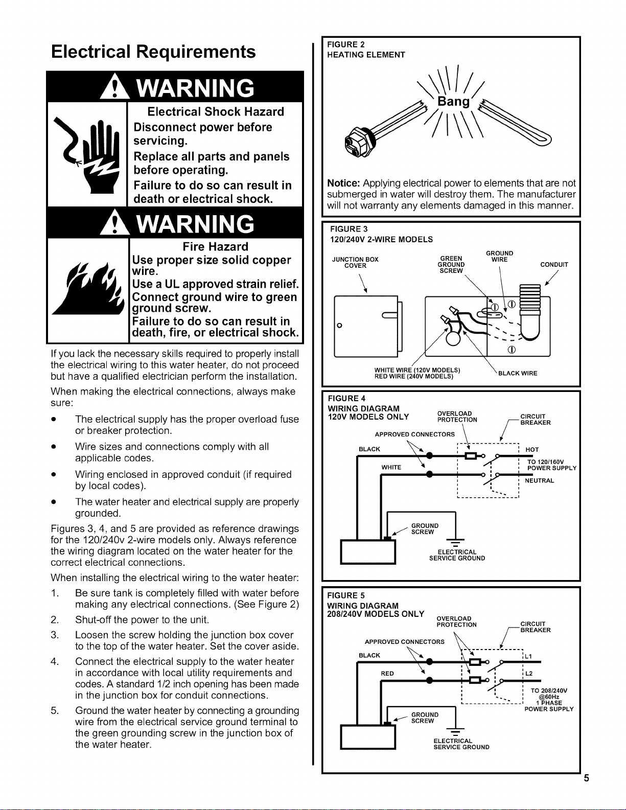
FIGURE 2
HEATING ELEMENT
\
/
Notice: Applying electrical power to elements that are not
submerged in water will destroy them. The manufacturer
will not warranty any elements damaged in this manner.
FIGURE 3
120/240V 2-WIRE MODELS
JUNCTION BOX
COVER
\
Iol
GREEN
GROUND
SCREW
WHITE WIRE (120V MODELS)
RED WIRE (240V MODELS)
GROUND
WIRE
BLACK WIRE
CONDUIT
FIGURE 4
WIRING DIAGRAM
OVERLOAD CIRCUIT
120V MODELS ONLY PROTECTION
• /-- BREAKER
APPROVED CONNECTORS .__. /
BLACK _ _--_ ..... ] HOT
X.- ' _Yl_',' To_120/160v
WHITE -I ', ' ' POWER SUPPLY
[
A
ILz
i
i
i
GROUND --LSCREW
I NEUTRAL
i i
i
._.
ELECTRICAL
SERVICE GROUND
FIGURE 5
WIRING DIAGRAM
208/240V MODELS ONLY
OVERLOAD
PROTECTION CIRCUIT
APPROVED CONNECTORS _%. S BREAKER
BLACK_. ,_-_'--........'=L,
I RED\ i_ ',_ =L2
a -_ : "'1 o ',e '.
II .....
2;i2 ;;LY
L 1 -
ELECTRICAL
SERVICE GROUND
Loading ...
Loading ...
Loading ...