Operator's ManuaJ
®
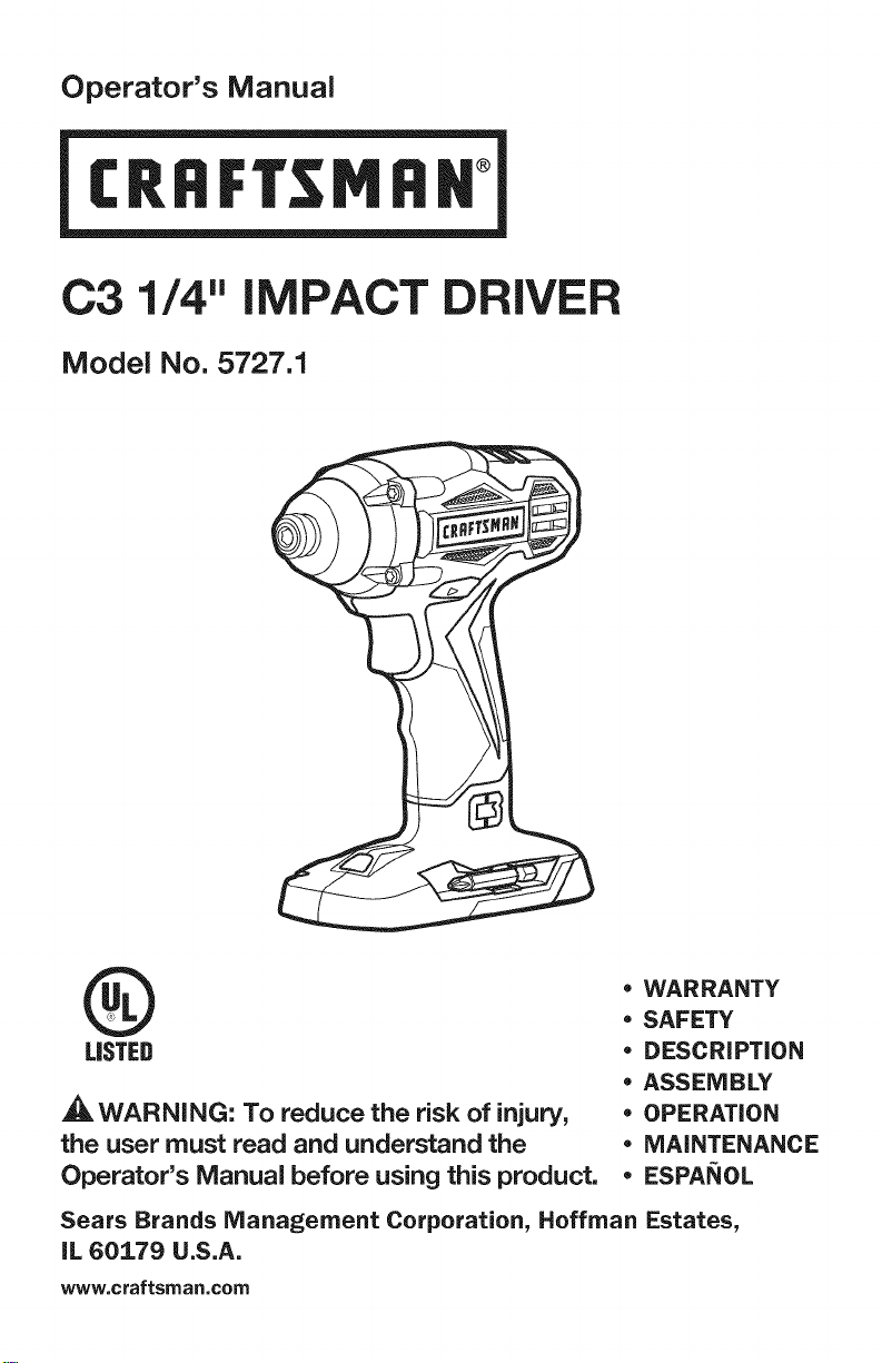
C3 1/4" iMPACT DRIVER
Model No. 5727.1
®
LISTED
_WARNING: To reduce the risk of injury,
the user must read and understand the
Operator's Manual before using this product.
* WARRANTY
* SAFETY
* DESCRiPTiON
* ASSEMBLY
* OPERATION
* MAINTENANCE
* ESPANOL
Sears Brands Management Corporation, Hoffman Estates,
IL 60179 U.S.A.
www, craftsman,com
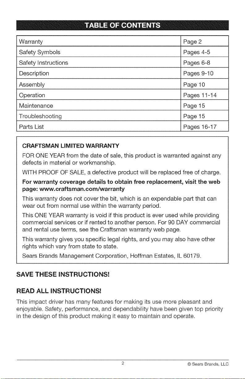
Warranty Page 2
Safety Symbols Pages 4-5
Safety Instructions Pages 6-8
Description Pages 9-10
Assembly Page 10
Operation Pages 11-14
Maintenance Page 15
Troubleshooting Page 15
Parts List Pages 16-17
CRAFTSMAN LiMiTED WARRANTY
FOR ONE YEAR from the date of sale, this product is warranted against any
defects in material or workmanship.
WITH PROOF OF SALE, a defective product will be replaced free of charge.
For warranty coverage details to obtain free replacement, visit the web
page: www.craftsman.com/warranty
This warranty does not cover the bit, which is an expendable part that can
wear out from normal use within the warranty period.
This ONE YEAR warranty is void if this product is ever used while providing
commercial services or if rented to another person. For 90 DAY commercial
and rental use terms, see the Craftsman warranty web page.
This warranty gives you specific legal rights, and you may also have other
rights which vary from state to state.
Sears Brands Management Corporation, Hoffman Estates, IL 60179.
SAVE THESE INSTRUCTIONS!
READ ALL INSTRUCTIONS!
This impact driver has many features for making its use more pleasant and
enjoyable. Safety, performance, and dependability have been given top priority
in the design of this product making it easy to maintain and operate.
2 © Sears Brands, LLC
,_, DANGER: People with electronic devices, such as pacemakers, should
consult their physician(s) before using this product. Operation of electrical
equipment in close proximity to a heart pacemaker could cause interference or
failure of the pacemaker.
_,WARNING: Some dust created by power sanding, sawing, grinding, drilling
and other construction activities contains chemicals known to the state of
California to cause cancer, birth defects or other reproductive harm. Some
examples of these chemicals are:
• Lead from lead-based paints
Crystalline silica from bricks and cement and other masonry products, and
Arsenic and chromium from chemically-treated lumber.
Your risk from these exposures varies, depending on how often you do this type
of work. To reduce your exposure to these chemicah work in a well ventilated
area, and work with approved safety equipment, such as those dust masks that
are specially designed to filter out microscopic particles.
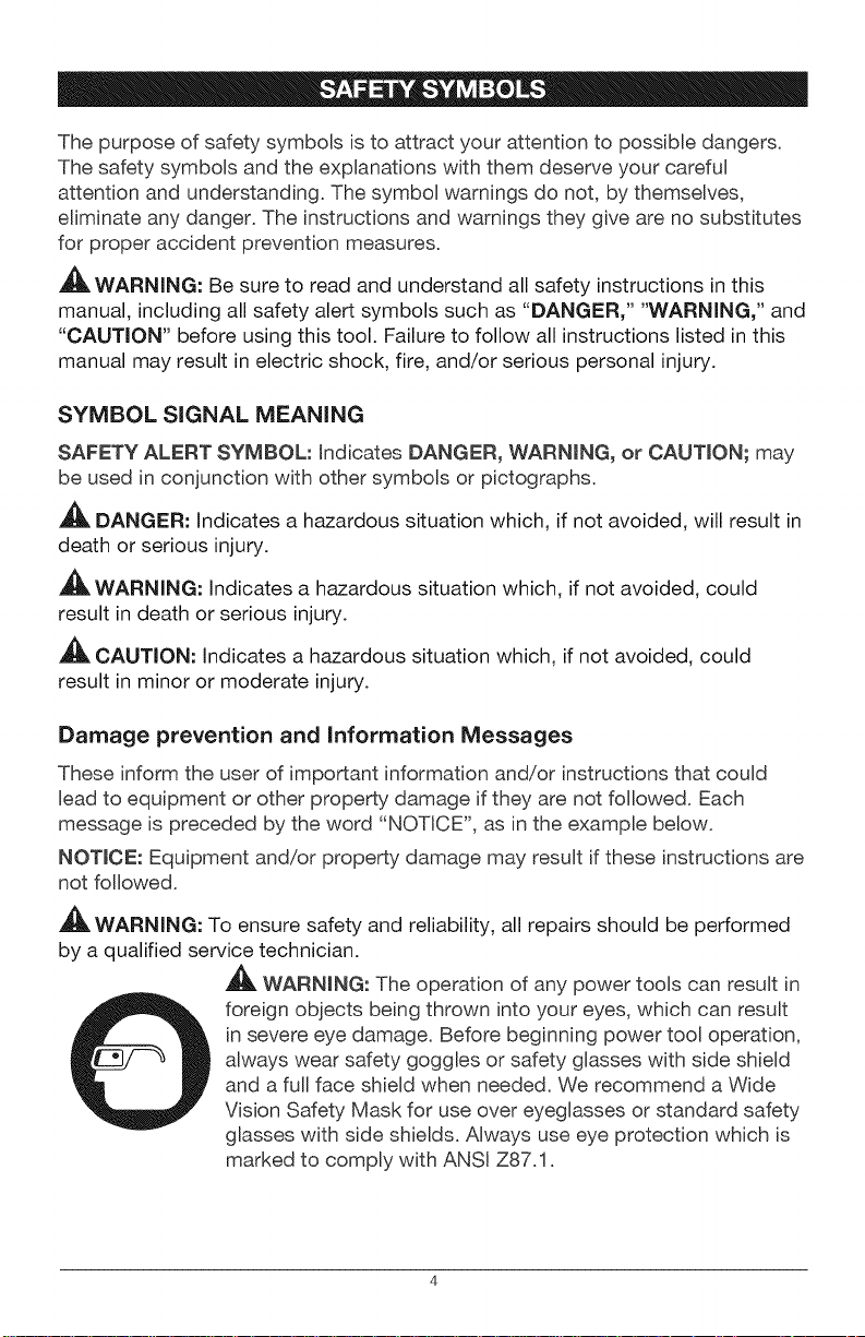
Thepurposeofsafetysymbolsistoattractyourattentiontopossibledangers.
Thesafetysymbolsandtheexplanationswiththemdeserveyourcareful
attentionandunderstanding.Thesymbolwarningsdonot,bythemselves,
eliminateanydanger.Theinstructionsandwarningstheygivearenosubstitutes
forproperaccidentpreventionmeasures.
,_, WARNING: Be sure to read and understand all safety instructions in this
manual, including all safety alert symbols such as "DANGER," "WARNING," and
"CAUTION" before using this tool. Failure to follow all instructions listed in this
manual may result in electric shock, fire, and/or serious personal injury.
SYMBOL SIGNAL MEANING
SAFETY ALERT SYMBOL: indicates DANGER, WARNING, or CAUTION; may
be used in conjunction with other symbols or pictographs.
DANGER: Indicates a hazardous situation which, if not avoided, will result in
death or serious injury.
,_, WARNING: Indicates a hazardous situation which, if not avoided, could
result in death or serious injury.
_, CAUTION: Indicates a hazardous situation which, if not avoided, could
result in minor or moderate injury.
Damage prevention and Information Messages
These inform the user of important information and/or instructions that could
Beadto equipment or other property damage if they are not followed. Each
message is preceded by the word "NOTICE", as in the example below.
NOTICE: Equipment and/or property damage may result if these instructions are
not followed.
_WARNING: To ensure safety and reliability, all repairs should be performed
by a qualified service technician.
WARNING: The operation of any power tools can result in
foreign objects being thrown into your eyes, which can result
in severe eye damage. Before beginning power tool operation,
always wear safety goggles or safety glasses with side shield
and a full face shield when needed. We recommend a Wide
Vision Safety Mask for use over eyeglasses or standard safety
glasses with side shields. Always use eye protection which is
marked to comply with ANSI Z87.1.
SAVE THESE iNSTRUCTiONS
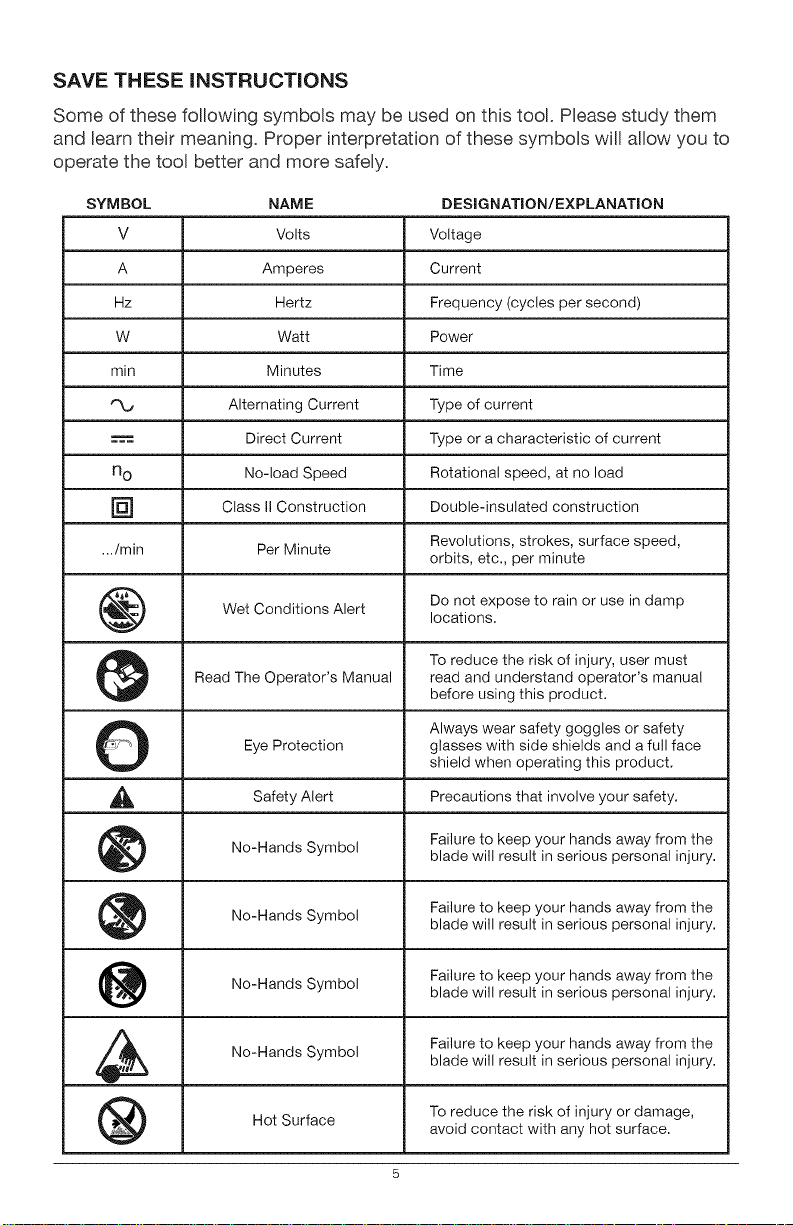
Some of these following symbols may be used on this tool. Please study them
and Beam their meaning. Proper interpretation of these symbols will allow you to
operate the tool better and more safely.
SYMBOL NAME DESIGNATION/EXPLANATION
V Volts Voltage
A Amperes Current
Hz Hertz Frequency (cycles per second)
W Watt Power
min Minutes Time
Alternating Current Type of current
Direct Current Type or a characteristic of current
n O No-load Speed Rotational speed, at no load
[] Class II Construction Double-insulated construction
.../min Per Minute Revolutions, strokes, surface speed,
orbits, etc., per minute
Wet Conditions Alert Do not expose to rain or use in damp
locations.
To reduce the risk of injury, user must
Read The Operator's Manual read and understand operator's manual
before using this product.
O Always wear safety goggles or safety
Eye Protection glasses with side shields and a fulI face
shield when operating this product.
Alert Precautions that involve
Safety your safety.
No=Hands Symbol Failure to keep your hands away from theblade will result in serious personal injury.
No=Hands Failure to keep your hands away from the
Symbol
blade will result in serious personal injury.
No-Hands Failure to keep your hands away from the
Symbol
blade will result in serious personal injury.
No-Hands Symbol Failure to keep your hands away from the
blade will result in serious personal injury.
Hot Surface To reduce the risk of injury or damage,
avoid contact with any hot surface.
5
GENERAL POWER TOOL SAFETY WARNINGS
,_ WARNING: Read aft safety warnings and instructions. Failure to follow the
warnings and instructions may result in electric shock, fire and/or serious injury.
Save all warnings and instructions for future reference.
The term "power tool" in the warnings refers to your mains=operated (corded)
power tool or battery=operated (cordless) power tool.
WORK AREA SAFETY
• Keep work area clean and well lit. Cluttered or dark areas invite accidents.
• Do not operate power tools in explosive atmospheres, such as in the
presence of flammable liquids, gases or dust. Power tools create sparks
which may ignite the dust or fumes.
= Keep children and bystanders away while operating a power tool.
Distractions can cause you to lose control.
ELECTRICAL SAFETY
• Power tool plugs must match the outlet. Never modify the plug in any
way. Do not use any adaptor plugs with earthed (grounded) power tools.
Unmodified plugs and matching outlets will reduce risk of electric shock
• Avoid body contact with earthed or grounded surfaces such as pipes,
radiators, ranges and refrigerators. There is an increased risk of electric
shock if your body is earthed or grounded.
• Do not expose power tools to rain or wet conditions. Water entering a
power tool will increase the risk of electric shock.
• Do not abuse the cord. Never use the cord for carrying, pulling or
unplugging the power tool. Keep cord away from heat, oil, sharp edges or
moving parts. Damaged or entangled cords increase the risk of electric shock.
• When operating a power tool outdoors, use an extension cord suitable
for outdoor use. Use of a cord suitable for outdoor use reduces the risk of
electric shock.
if operating a power tool in a damp location is unavoidable, use a
ground fault circuit interrupter (GFCl} protected supply. Use of a GFCI
reduces the risk of electric shock.
PERSONAL SAFETY
• Stay alert, watch what you are doing and use common sense when
operating a power tool. Do not use tool while tired or under the
influence of drugs, alcohol, or medication. A moment of inattention while
operating power tools may result in serious personal injury.
• Use personal protective equipment. Always wear eye protection. Protective
equipment such as dust mask, non-skid safety shoes, hard hat, or hearing
protection used for appropriate conditions will reduce personal injuries.
• Prevent unintentional starting. Ensure the switch is in the off-position
before connecting to power source and/or battery pack, picking up or
carrying the tool. Carrying power tools with your finger on the switch or
energizing in power tools that have the switch on invites accidents.
• Remove any adjusting key or wrench before turning the power tool
on. A wrench or a key left attached to a rotating part of the power tool may
result in personal injury.
• Do not overreach. Keep proper footing and balance at all times. This
enables better control of the power tool in unexpected situations.
• Dress properly. Do not wear loose clothing or jewelry. Keep your hair,
clothing and gloves away from moving parts. Loose clothes, jewelry or
long hair can be caught in moving parts.
• If devices are provided for the connection of dust extraction and
collection facilities, ensure these are connected and properly used. Use
of these devices can reduce dust-related hazards.
POWER TOOL USE AND CARE
• Do not force the power tool. Use the correct power tool for your
application. The correct power tool will do the job better and more safely at
the rate for which it was designed.
• Do not use the power tool if the switch does not turn it on and off. Any
power tool that cannot be controlled with the switch is dangerous and must
be repaired.
• Disconnect the plug from the power source andlor the battery pack
from the power tool before making any adjustments, changing
accessories, or storing power tools. Such preventive safety measures
reduce the risk of starting the power tool accidentally.
• Store idle power tools out of the reach of children and do not allow
persons unfamiliar with the power tool or these instructions to operate
the power tool. Power tools are dangerous in the hands of untrained users.
• Maintain power tools. Check for misalignment or binding of moving
parts, breakage of parts and any other condition that may affect the
power tool's operation, if damaged, have the power tool repaired
before use. Many accidents are caused by poorly maintained power tools.
Keepcuttingtoolssharpandclean.Properlymaintainedcuttingtoolswith
sharpcuttingedgesarelesslikelytobindandareeasiertocontrol.
Usethepower tool, accessories, too[ bits, etc. in accordance with
these instructions, taking into account the working conditions and the
work to be performed. Use of the power tool for operations different from
those intended could result in a hazardous situation.
BATTERY TOOL USE AND CARE
• Recharge only with the charger specified by the manufacturer. A
charger that is suitable for one type of battery pack may create a risk of fire
when used with another battery pack.
• Use power tools only with specifically designated battery packs. Use of
any other battery packs may create a risk of injury and fire.
= When battery pack is not in use, keep it away from other metal objects,
like paper clips, coins, keys, nails, screws or other small metal objects
that can make a connection from one terminal to another. Shorting the
battery terminals together may cause burns or a fire.
= Under abusive conditions, liquid may be ejected from the battery;
avoid contact. If contact accidentally occurs, flush with water. If liquid
contacts eyes, additionally seek medical help. Liquid ejected from the
battery may cause irritation or burns.
SERVICE
Have your power too[ serviced by a qualified repair person using only
identical replacement parts. This will ensure that the safety of the power
tool is maintained.
Follow instructions in the Maintenance section of this manual. Use of
unauthorized parts or failure to follow Maintenance instructions may create
a risk of shock or injury.
SPECiFiC SAFETY RULES FOR iMPACT DRIVER
Hold power tools by their insulated gripping surfaces when performing
an operation where the cutting tool may contact hidden wiring. If a
cutting accessory contacts a "live" wire, it may make exposed metal parts
of the power tool "live" and could give the operator an electric shock.
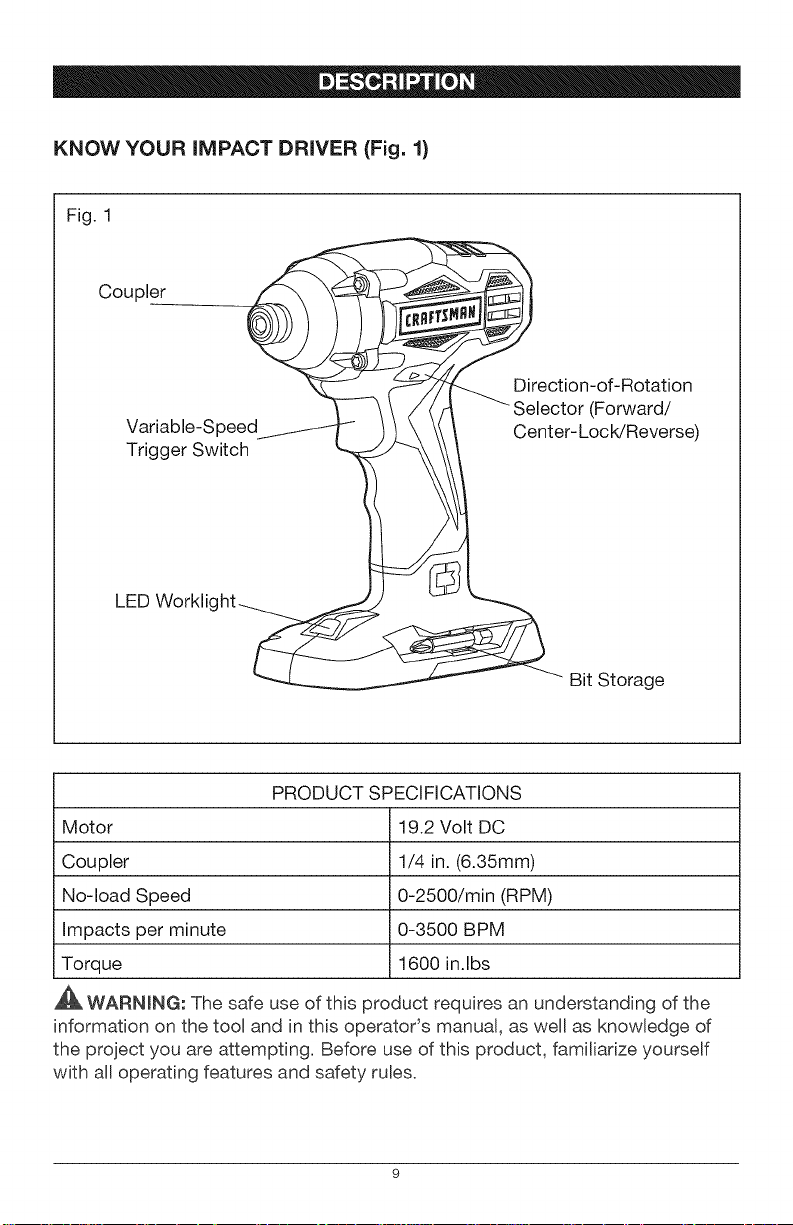
KNOW YOUR iMPACT DRIVER (Fig. 1)
Fig. 1
Coupler
Variable-Speed
Trigger Switch
Direction-of-Rotation
(Forward/
Center-LocWReverse)
LED Worklight-__
Bit Storage
PRODUCT SPECIFICATIONS
Motor 19.2 Volt DC
Coupler 1/4 in. (6.35mm)
No-load Speed 0-2500/min (RPM)
Impacts per minute 0-3500 BPM
Torque 1600 in.lbs
WARNING: The safe use of this product requires an understanding of the
information on the tool and in this operatoCs manual, as well as knowledge of
the project you are attempting. Before use of this product, familiarize yourself
with all operating features and safety rules.
VARIABLE SPEED
The variable=speed trigger switch delivers higher speed with increased trigger
pressure and Bowerspeed with decreased trigger pressure.
FORWARD/CENTER=LOCK/REVERSE SELECTOR
The impact driver has a direction=of=rotation selector located above the trigger
switch for changing the direction of bit rotation. Setting the trigger switch in the
OFF (centerqock) position helps reduce the possibility of accidental starting
when not in use.
LED WORKLIGHT
The LED worklight, located on the base of the impact driver, illuminates
when the trigger switch is depressed. This feature provides extra Bight for
increased visibility.
,&
_A, WARNING: If any parts are broken or missing, do not attempt to attach the
battery pack or operate the impact driver until the broken or missing parts are
replaced. Failure to do so could result in possible serious injury.
_, WARNING: Do not attempt to modify this impact driver or create
accessories not recommended for use with this impact driver. Any such
alteration or modification is misuse and could result in a hazardous condition
leading to possible serious injury.
_, WARNING: To prevent accidental starting that could cause serious personal
injury, always remove the battery pack from the impact driver when changing bits.
UNPACKING
This product has been shipped completely assembled.
• Carefully remove the tool and any accessories from the carton. Make sure
that all items listed in the packing list are included.
Inspect the tool carefully to make sure that no breakage or damage
occurred during shipping.
Do not discard the packing material until you have carefully inspected and
satisfactorily operated the tool.
If any parts are damaged or missing, please return the tool to the place
of purchase.
PACKING LIST
Impact driver, bit (installed on the impact driver) and operator's manual
10
This product will accept Craftsman C3 19.2V lithium-ion battery packs. For
complete charging instructions, refer to the Operator's Manual for the battery
packs and chargers.
_, WARNING: To prevent accidental starting that could cause serious personal
injury, always remove the battery pack from the tool when assembling parts,
making adjustments, installing or removing bit, cleaning, or when it is not in use.
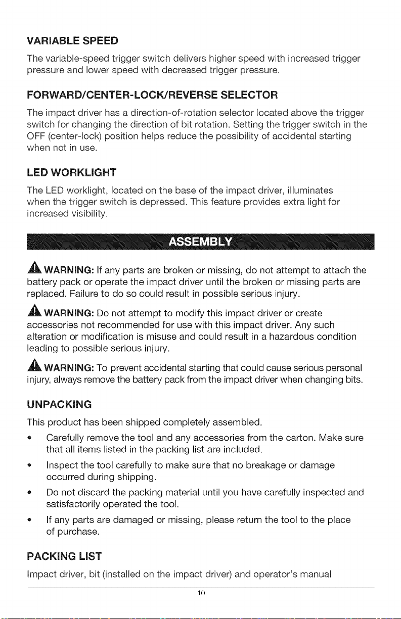
TO ATTACH BATTERY
PACK (Fig, 2)
1. Lock the trigger switch on the
impact driver by placing the
direction-of-rotation (forward/
center-lock/reverse) selector
in the center position.
2. Align the raised rib on the
battery pack with the groove
inside the impact driver, and
then insert the battery pack
into the tool.
Fig. 2
Latch
Battery-
Release
Button
NOTICE: Make sure that the latch on the battery pack snaps into place and
the battery pack is secured to the tool before beginning operation. Improper
assembly of the battery pack can cause damage to internal components.
TO DETACH BATTERY PACK (Fig. 2)
1. Lock the trigger switch on the impact driver by placing the direction-of-
rotation (forward/center-locWreverse) selector in the center position.
2. Depress both battery-release buttons, located on the sides of the battery
pack, to release the battery pack.
3. Pull the battery pack out and remove it from the tool.
,_. WARNING: Battery tools are always in operating condition. Therefore, the
direction-of-rotation selector should always be locked when the tool is not in use
or when carrying the tool at your side.
11
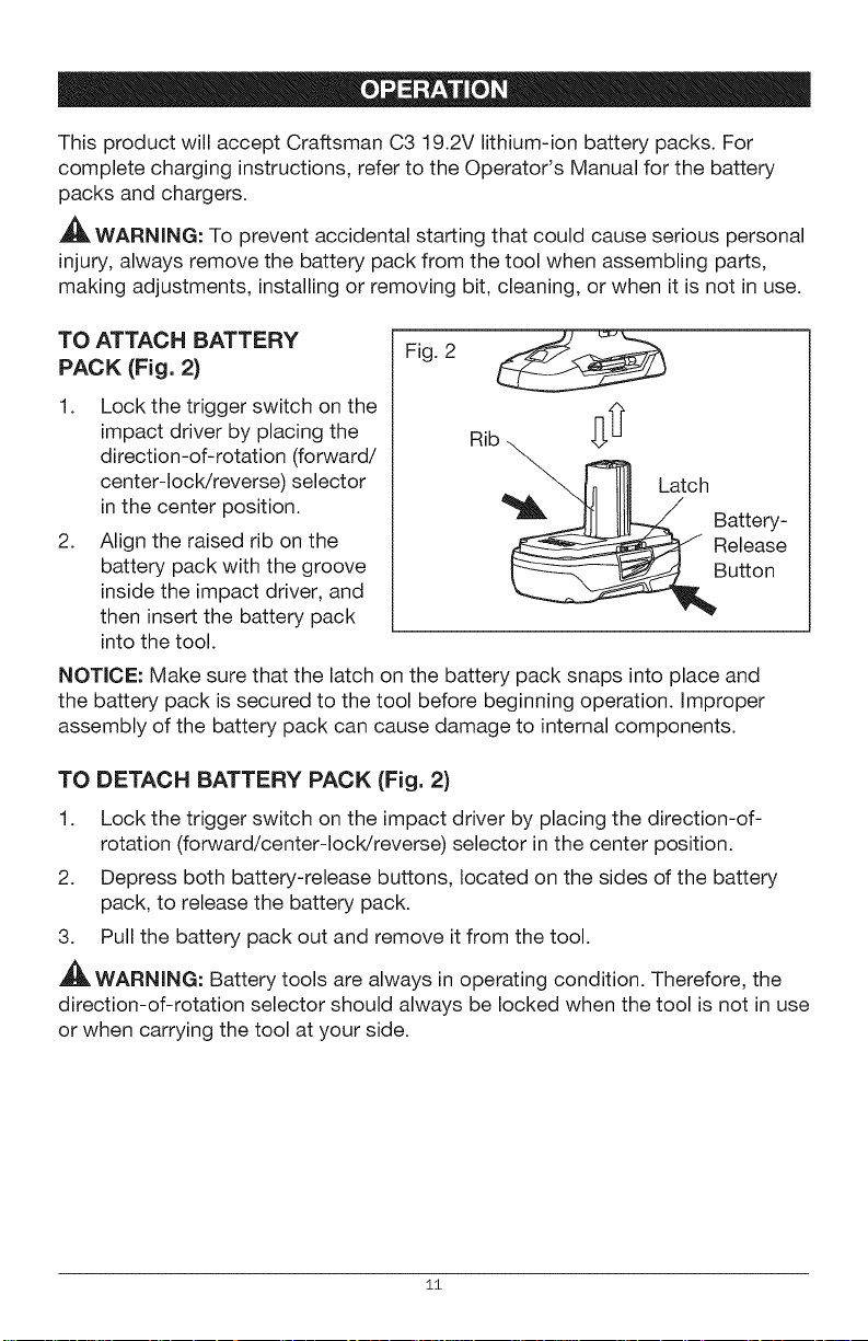
TRIGGER SWITCH (Fig. 3)
To turn the impact driver ON,
depress the trigger switch.
To turn it OFF, release the
trigger switch.
VARIABLE SPEED (Fig. 3)
The variable-speed trigger
switch delivers higher speed
with increased trigger pressure
and lower speed with decreased
trigger pressure.
DIRECTION=OF-
ROTATION SELECTOR
(FORWARD/CENTER- LOCK/
REVERSE) (Fig. 4}
The direction of bit rotation is
reversible and is controlled by
a selector located above the
trigger switch.
With the impact driver held in
normal operating position, as
shown in Fig. 4:
1.
Fig. 3
Variable-Speed l -T- 1
Trigger Switch r I I
I
Fig. 4
• % I
] I _ Direction-of-
Rotation Selector
Position the direction-of-rotation selector to the left of the tool for
forward rotation.
2. Position the direction-of-rotation selector to the right of the tool for reverse.
3. Setting the switch in the OFF (center-lock) position helps reduce the
possibility of accidental starting when not in use.
NOTICE: To prevent gear damage, always allow the impact driver to come to a
complete stop before changing the direction of rotation.
NOTICE: The impact driver will not run unless the direction-of-rotation selector
is engaged fully to the left or right.
ELECTRIC BRAKE
To stop the impact driver, release the trigger switch and allow the tool to come
to a complete stop. The electric brake quickly stops the coupler from rotating.
This feature engages automatically when you release the trigger switch.
12
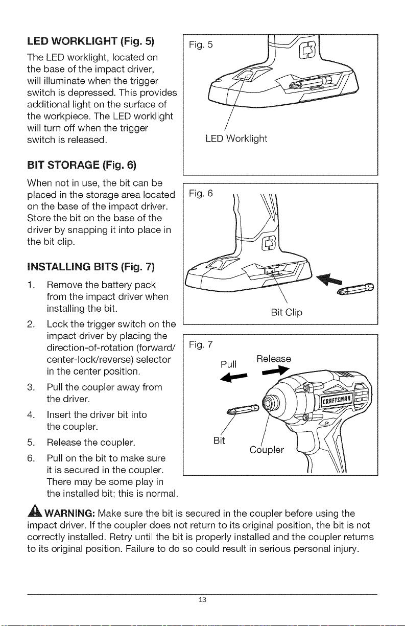
LED WORKLIGHT (Fig. 5)
The LED worklight, located on
the base of the impact driver,
will illuminate when the trigger
switch is depressed. This provides
additional light on the surface of
the workpiece. The LED worklight
will turn off when the trigger
switch is released.
BIT STORAGE (Fig. 6)
When not in use, the bit can be
placed in the storage area located
on the base of the impact driver.
Store the bit on the base of the
driver by snapping it into place in
the bit clip.
INSTALLING BITS (Fig. 7)
1. Remove the battery pack
from the impact driver when
installing the bit.
2. Lock the trigger switch on the
impact driver by placing the
direction-of-rotation (forward/
center-lock/reverse) selector
in the center position.
3. Pull the coupler away from
the driver.
4. Insert the driver bit into
the coupler.
5. Release the coupler.
6. Pull on the bit to make sure
it is secured in the coupler.
There may be some play in
the installed bit; this is normal.
Fig.
LED Worklight
Fig. 6 ____
Bit Clip
Fig. 7
Release
Pull
i
,_ WARNING: Make sure the bit is secured in the coupler before using the
impact driver. If the coupler does not return to its original position, the bit is not
correctly installed. Retry until the bit is properly installed and the coupler returns
to its original position. Failure to do so could result in serious personal injury.
13
REMOVING BITS (Fig. 7)
1. Remove the battery pack from the impact driver when removing the bit.
2. Lock the trigger switch on the impact driver by placing the direction-of-
rotation (forward/center-locWreverse) selector in the center position.
3. Pull the coupler away from the driver.
4. Remove the driver bit from the coupler..
WARNING: Use protective gloves when removing the bit from the tool, or
first allow the bit to cool down. The bit may be hot after prolonged use.
_, CAUTION: The impact driver is not designed to be used as a drill.
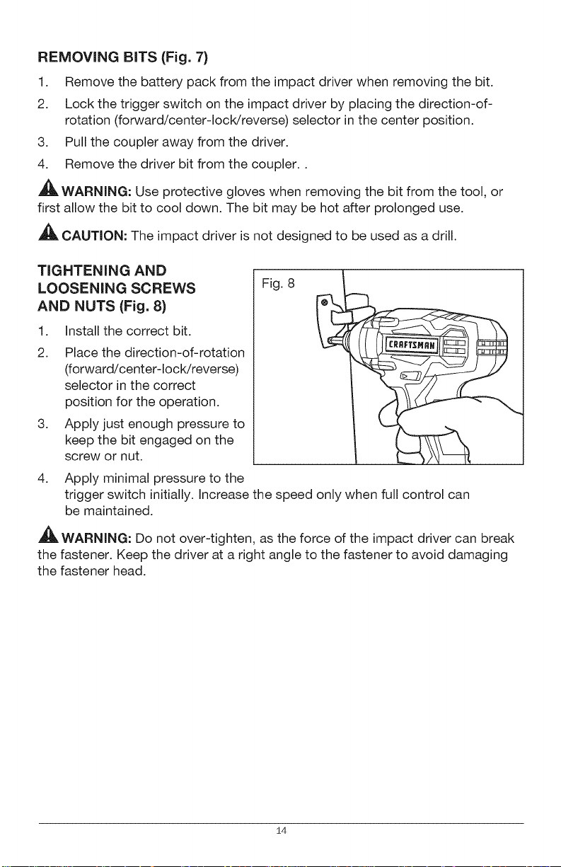
TIGHTENING AND
LOOSENING SCREWS
AND NUTS (Fig. 8)
1. Install the correct bit.
2. Place the direction-of-rotation
(forward/center-lock/reverse)
selector in the correct
position for the operation.
3. Apply just enough pressure to
keep the bit engaged on the
screw or nut.
Fig. 8
4. Apply minimal pressure to the
trigger switch initially. Increase the speed only when full control can
be maintained.
,_ WARNING: Do not over-tighten, as the force of the impact driver can break
the fastener. Keep the driver at a right angle to the fastener to avoid damaging
the fastener head.
14
A
,_L WARNING: To avoid serious personal injury, always remove the battery
pack from the tool when cleaning or performing any maintenance.
,_ WARNING: Always wear safety goggles or safety glasses with side shields
when using compressed air to clean the tool. If the operation is dusty, also wear
a dust mask.
GENERAL MAINTENANCE
Avoid using solvents when cleaning plastic parts. Most plastics are susceptible
to damage from various types of commercial solvents and may be damaged by
their use. Use clean clothes to remove dirt, dust, oil, grease, etc.
_1_ WARNING: Do not at any time let brake fluids, gasoline, petroleum-based
products, penetrating oils, etc. come in contact with plastic parts. Chemicals
can damage, weaken or destroy plastic which may result in serious
personal injury.
,_ WARNING: When servicing, use only identical craftsman replacement parts.
Use of any other parts may create a hazard or cause product damage. To
ensure safety and reliability, all repairs should be performed by a qualified
service technician.
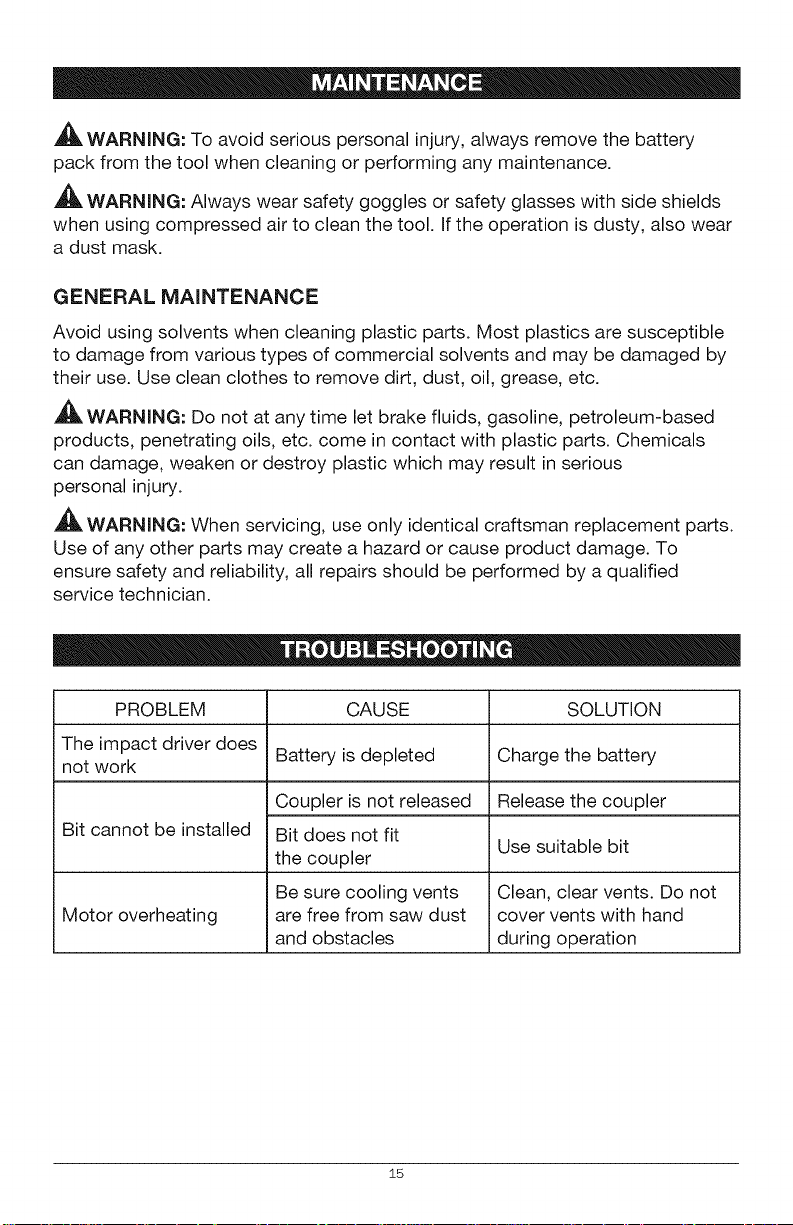
PROBLEM CAUSE
The impact driver does Battery is depleted
not work
Bit cannot be installed
Motor overheating
Coupler is not released
Bit does not fit
the coupler
Be sure cooling vents
are free from saw dust
and obstacles
SOLUTION
Charge the battery
Release the coupler
Use suitable bit
Clean, clear vents. Do not
cover vents with hand
during operation
15
L
Y
8
@
/
/
\
, .. -.
, ---Cb.
/
[ ,'
i/
>

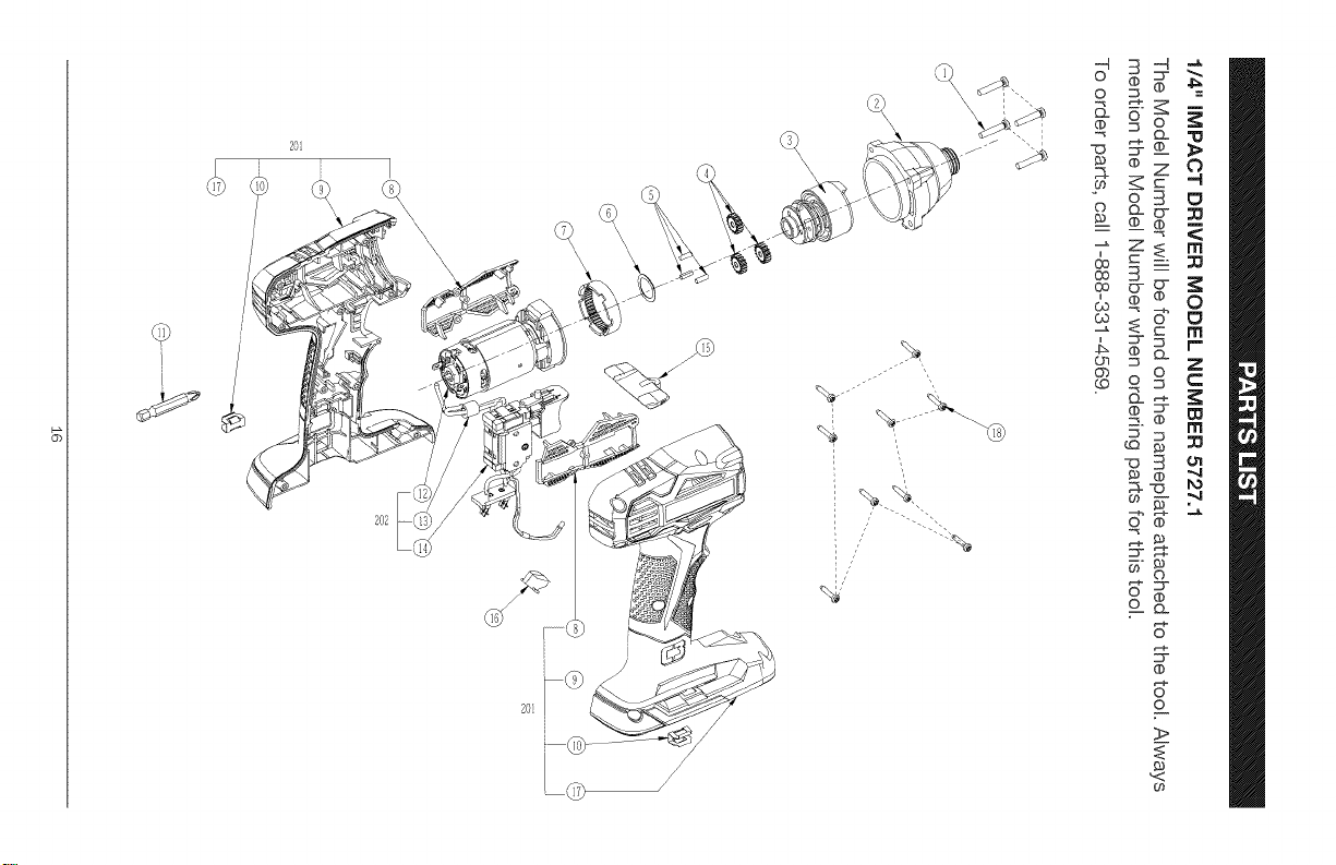
1/4" mMPACT DRmVER MODEL NUMBER 5727.1
The Model Number will be found on the nameplate of the tool Always mention
the Model Number when ordering parts for this tool
To order parts, call 1-888-331-4569°
5610248000 Tapping Screw
]2 2823871000 Front Gear Housing Assembly 1
] 3 2823683000 Impact Block Assembly 1
]4 3520745000 Planet Gear 3
5 3550147000 Needle Pin 3
6 5650223000 Washer 1
7 3520744000 Ring Gear 1
201 2823983000 L R Housing Set 1
8 3127553000 Support 2
]9 3321803000 Left Housing 1
10 3703673000 Bits Holder 2
11 3810017000 Screw Bit 1
202 2823984000 Control Assembly 1
12 2790376000 Motor and Gear Case Assembly 1
13 3680140000 Magnet Ring 1
14 2823966000 Contact Receptacle Assembly 1
15 3126501000 F/R Button 1
16 3126500000 LED Cover 1
17 3321802000 Right Housing 1
18 5610241000 Screw 9
17

18
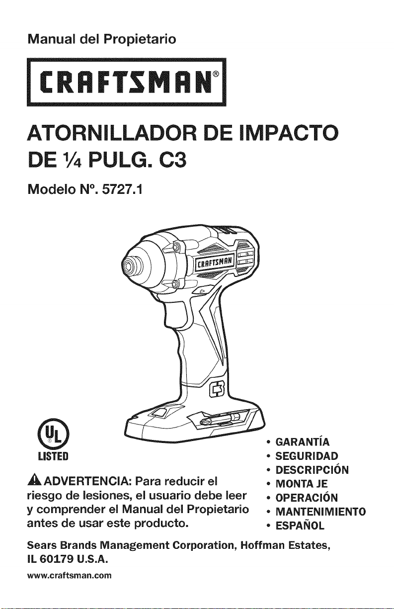
Manual del Propietario
®
ATORNILLADOR DE IMPACTO
DE % PULG. C3
Modelo N°. 5727.1
®
LISTED
,_ ADVERTENCIA: Para reducir el
riesgo de lesiones, el usuario debe leer
y comprender el Manual del Propietario
antes de usar este producto.
,, GARANTJA
• SEGURIDAD
. DESCRIPCi6N
• MONTA JE
• OPERACION
• MANTENIMIENTO
• ESPANOL
Sears Brands Management Corporation, Hoffman Estates,
IL 60179 U.S.A.
www, craftsman,com
Garantia P&gina 20
Simbolos de Seguridad Paginas 22-23
Instrucciones de Seguridad Paginas 24-26
Descripcion Paginas 28-29
Montaje Paginas 29-30
Operacion Paginas 30-34
Mantenimiento Pagina 34
ldentificaci6n y Soluci6n de Problemas Pagina 34
GARANTiA LIMiTADA DE CRAFTSMAN
DURANTE UN ANO desde la fecha de vender, este producto cuenta con
garantia contra cualquier clase de defectos de material o de mano de obra.
MEDIANTE UNA PRUEBA DE VENDER, el producto defectuoso se
reemplazar& sin costo alguno.
Si desea obtener detalles sobre la cobertura de garantia para obtener un
reemplazo sin costo, visite la p&gina web: www.craftsman.com/warranty
Esta garantia no cubre la broca, porque es una pieza prescindible que
pueden desgastarse debido al uso normal dentro del periodo de garantia.
La presente garantia de UN ANO quedar& anulada si este producto se usa
para brindar servicios comerciales o si se alquila a terceros. Para consultar
los terminos de uso comercial y de alquiler de 90 DiAS, visite la pagina web
sobre garantia de Craftsman.
Esta garantia le otorga derechos legales especificos y usted puede contar
con otros derechos, que pueden variar de estado a estado.
Sears Brands Management Corporation, Hoffman Estates, IL 60179.
iGUARDE ESTAS INSTRUCCIONES!
iLEA TODAS LAS INSTRUCCIONES!
Este atornfllador de impacto inal&mbdco cuenta con varias caracteristicas
para hacer su uso mas agradable y placentero. Durante el dise_o de esta
herramienta, la seguddad, el rendimiento y Baconfiabflidad han sido las
pnoddades pdncipales, adem&s de Basencfllez de mantenimiento y de
operaci6n.
20 © Sears Brands, LLC
_, PELIGRO: La gente con los accesorios electr6nicos, como los
estimuladores cardiacos, deben consultar sus m6dicos antes de usar esto
producto. La operaci6n de los equipos el6ctricos cerca de un estimulador
cardiaco puede causar la interferencia o la averia del estimulador cardiaco.
,_ ADVERTENClA: Unos polvos creado por lijadoras mec&nicas, las sierras
mec&nicas, las amoladoras electricas, los taladros y otras actividades de la
construcci6n contienen los elementos quimicos que son conocidos para el
estado de California de causar el cancer, los defectos de nacimientos o otros
daSos reproductores. Unos ejemplos de estos elementos quimicos estan:
• Plomo de la pintura con base de plomo
El silice cristalino de los ladrillos y cemento y otras productas de la
alba_ileria, y
• El arsenic y el cromo de la madera tratada quimicamente
Su riesgo de 6stas exposici6nes varia, dependiente con qu6 frecuencia haga
esto typo de trabajo. Para reducer su exposici6n a estos elementos quimicos:
trabaje en un lugar bien ventilada, y trabaje con el equipo de seguridad, como
las m&scaras antipolvo que han diseSado especfficamente para filtrar las
particulas microsc6picas.
2±
El objeto de los simbolos de seguridad es atraer su atenci6n sobre posibles peligros.
Los simbolos de seguridad y las explicaciones junto a elias ameritan su
cuidadosa atenci6n y comprensi6n. Los simbolos de advertencia no eliminan
los peligros por si solos. Las instrucciones y advertencias que ofrecen no
reemplazan las medidas adecuadas de prevencion de accidentes.
,_ ADVERTENCIA: AsegOrese de leer y comprender todas las instrucciones de
seguridad de este manual, incluyendo todos los simbolos de alerta de seguridad,
tales como "PELIGRO", "ADVERTENClA" y "PRECAUClON" antes de utilizar esta
perforadora/atornilladora. No seguir todas las instrucciones listadas a continuacion
puede generar una descarga electrica, un incendio y/o graves lesiones corporales.
SIGNIFICADO DE LOS SiMBOLOS
,_ PELIGRO: Indica una situacion peligrosa que, si no se evita, puede provocar
la muerte o una lesion grave. Esta palabra debe limitarse a las stiuaciones
mAs extremas.
_1_ ADVERTENClA: Indica una situacion peligrosa que, si no se evita, puede
provocar la muerte o una lesion grave.
_, PRECAUClON: Indica una situacion peligrosa que, si no se evita, puede
provocar una lesion menor o moderada.
Mensajes de informaci6n y de prevenci6n de da5os
Estos informan al usuario sobre informaciones y/o instrucciones importantes que
podrian provocar da_os al equipamiento o a la propiedad si no se siguen. Cada
mensaje estA precedido por la palabra "AVISO", como en el ejemplo siguiente:
AVlSO: Pueden provocarse daSos al equipamiento y/o a la propiedad si no se
cumplen estas instrucciones.
_IL ADVERTENClA: Para garantizar la seguridad y la confiabilidad, todas las
reparaciones deben set efectuadas pot un tecnico calificado.
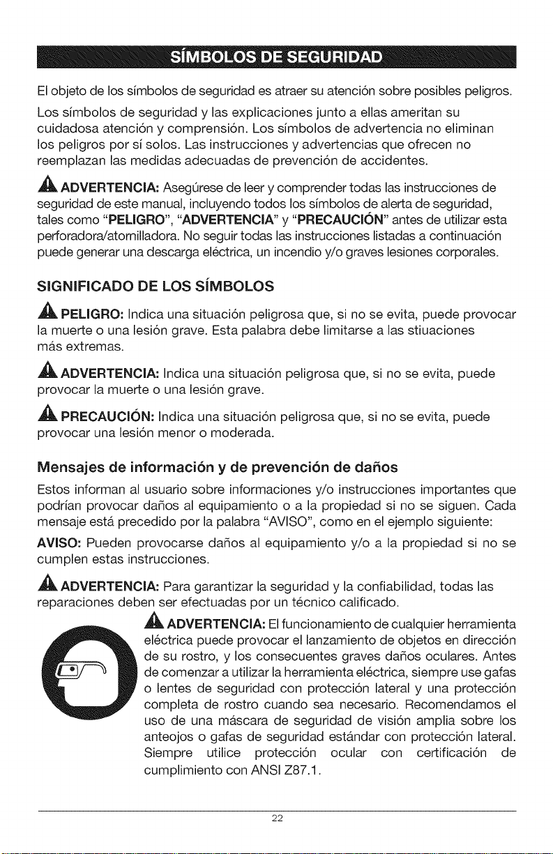
,_ ADVERTENClA: El funcionamiento de cualquier herramienta
electrica puede provocar el lanzamiento de objetos en direccion
de su rostro, y los consecuentes graves daSos oculares. Antes
de comenzar a utilizar la herramienta electrica, siempre use gafas
o lentes de seguridad con proteccion lateral y una proteccion
completa de rostro cuando sea necesario. Recomendamos el
uso de una mascara de seguridad de vision amplia sobre los
anteojos o gafas de seguridad estandar con proteccion lateral.
Siempre utilice proteccion ocular con certificacion de
cumplimiento con ANSI Z87.1.
22
GUARDE ESTAS INSTRUCCIONES
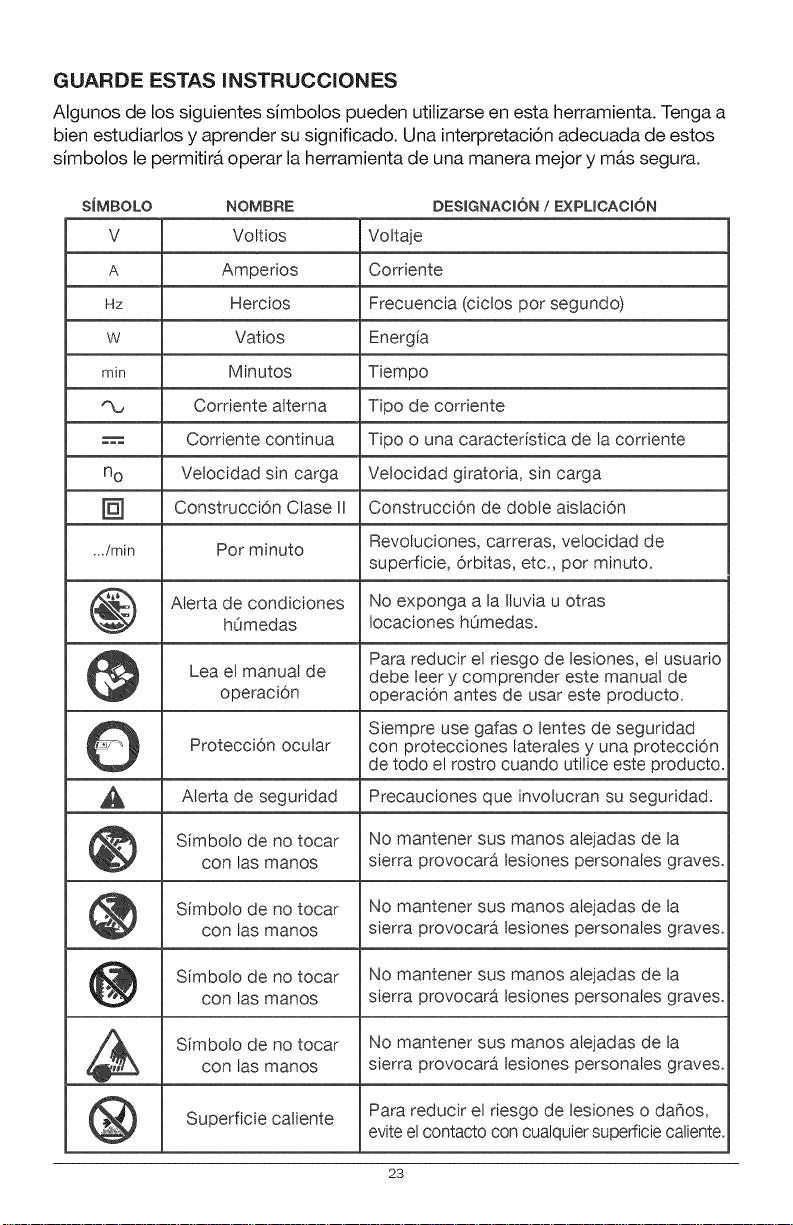
Algunos de los siguientes simbolos pueden utilizarse en esta herramienta. Tenga a
bien estudiarlos y aprender su significado. Una interpretacion adecuada de estos
simbolos le permitira operar la herramienta de una manera mejor y mas segura.
SiMBOLO NOMBRE DESIGNACION/ EXPLICACION
V Voltios Voltaje
A Ampedos Cordente
Hz Hercios Frecuencia (ciclos pot segundo)
w Vatios Energia
min Minutos Tiempo
Cordente alterna Tipo de cordente
H.,-= Cordente continua Tipo o una caracteristica de la cordente
no Velocidad sin carga Velocidad giratoda, sin carga
Construcci6n Clase II Construcci6n de doble aislaci6n
...imin Pot minuto Revoluciones, carreras, velocidad de
superficie, orbitas, etc., pot minuto.
Alerta de condiciones No exponga a la Iluvia u otras
hOmedas Iocaciones hOmedas.
Para reducir el riesgo de lesiones, el usuario
Lea el manual de debe leer y comprender este manual de
operaci6n operaci6n antes de usar este producto.
Siempre use gafas o lentes de seguridad
Protecci6n ocular con protecciones laterales y una protecci6n
de todo e! rostro cuando utilice este producto.
Alerta de seguridad Precauciones que involucran su seguridad.
Simbolo de no tocar No mantener sus manos alejadas de la
con las manos sierra provocara lesiones personales graves.
Simbolo de no tocar No mantener sus manos alejadas de la
con las manos sierra provocara lesiones personales graves.
Simbolo de no tocar No mantener sus manos alejadas de la
con las manos sierra provocara lesiones personales graves.
Simbolo de no tocar No mantener sus manos alejadas de la
con las manos sierra provocara lesiones personales graves.
Superficie caliente Para reducir el riesgo de lesiones o dafios,
evite elcontacto con cualquier superficie caliente.
23
ADVERTENCIAS GENERALES DE SEGURIDAD DE LAS
HERRAMIENTAS EL|=CTRICAS
,_, ADVERTENCIA: Lea y comprenda todas las instrucciones. No seguir todas
las instrucciones listadas a continuacion puede generar una descarga electrica, un
incendio y/o graves lesiones corporales. El t@mino "herramienta electrica" de todas
las advertencias listadas a continuacion hacen referencia a herramientas electricas
con cable o herramientas electricas operadas a bateria (inalambricas).
CONSERVE TODAS LAS ADVERTENCIAS E INSTRUCCIONES PARA
REFERENCIA FUTURA
SEGURIDAD EN EL AREA DE TRABAJO
= Mantenga el Area de trabajo limpia y bien iluminada. Las Areas
desordenadas u oscuras son propicias para los accidentes.
= No utilice herramientas el6ctricas en atm6sferas explosivas, come en
la presencia de liquidos inflamables, gases o polvillo. Las herramientas
electricas crean chispas, que pueden encender el polvillo o el humo.
= Mantenga a los niSos y a los transeQntes alejados mientras maneja esta
herramienta el6ctrica. Las distracciones pueden provocar la p@dida de control.
SEGURIDAD EL|=CTRICA
= Evite el contacto corporal con superficies con conexi6n a tierra, tales
come caSerias, radiadores, cocinas y refrigeradores. Existe un riesgo
mayor de descarga electrica si su cuerpo tiene conexi6n a tierra.
= Los enchufes de las herramientas el6ctricas deben pealer insertarse en
los tomacorrientes. Nunca modifique el enchufe de ninguna manera.
No utilice enchufes adaptadores con herramientas el6ctricas con
conexi6n a tierra. No modificar los enchufes y contar con el tomacorriente
adecuado reduciran el riesgo de una descarga electrica.
= No exponga las herramientas el_ctricas a la lluvia o a condiciones de
humedad. El agua que ingresa a la herramienta electrica incrementara el
riesgo de una descarga electrica.
= No maltrate el cable. Nunca utilice el cable para trasladar o
desenchufar la herramienta el_ctrica ni tire del mismo. Mantenga
el cable alejado del calor, aceite, extremes afilados o piezas en
movimiento. Los cables daSados o enredados incrementan el riesgo de
una descarga electrica.
24
= Cuando utiiice una herramienta el_ctrica ai aire libre, use un cable de
extensi6n especial para use al exterior. El uso de un cable adecuado
para el aire libre reduce el riesgo de una descarga electrica.
= Si no puede evitar el uso de una herramienta el_ctrica en un lugar
h_medo, utilice un suministro de energia protegido pot un interruptor
de circuito con descarga a tierra (GFCI, pot sus sigias en ingles). El uso
de un GFCI reduce el riesgo de una descarga electrica.
SEGURIDAD PERSONAL
• Mant_ngase alerta, preste atenci6n a Io que hace y tenga sentido
com_n cuando utilice una herramienta el_ctrica. No utilice una
herramienta el_ctrica si est_ cansado o bajo la influencia de drogas,
alcohol o alguna medicaci6n. Un momento de distracci6n mientras utiliza
herramientas electricas puede provocar lesiones personales graves.
= Utilice equipamiento de protecci6n personal. Siempre use protecci6n
ocular. El equipamiento de seguridad como las m&scaras antipolvillo,
zapatos antideslizantes, cascos o protecci6n auditiva utilizados para
condiciones apropiadas reducir&n las lesiones personales.
= Evite el encendido involuntario. Verifique que el interruptor se
encuentre en la posici6n OFF (apagado) antes de conectar a la fuente
de energia y/o a la bateria, levantar la herramienta o trasladarla.
Llevar herramientas electricas con el dedo sobre el interruptor o enchufar
herramientas que tienen el interruptor en la posici6n "ON" (encendido) es
una invitaci6n a sufrir un accidente.
• Quite las Ilaves ajustables antes de encender la herramienta el_ctrica.
Una Ilave de tuercas que se deja conectada a una pieza giratoria de la
herramienta puede provocar lesiones personales.
= No se estire de m&s. Mantenga una postura equilibrada y segura en
todo momento. Esto permite un mejor control de la herramienta electrica
en situaciones inesperadas.
= Vistase adecuadamente. No use vestimenta suelta o joyas. Mantenga su
cabello, ropa y guantes alejados de las piezas en movimiento. La ropa
suelta, joyas o cabello largo pueden engancharse en las piezas en movimiento.
= Si los dispositivos pueden conectarse a instalaciones de e×tracci6n
y recolecci6n de polvillo, aseg_rese de que se encuentren bien
conectados y se usen adecuadamente. El uso de estos dispositivos
puede reducir los riesgos relacionados con el polvillo.
25
USO Y CUIDADO DE LA HERRAMIENTA ELi_CTRICA
= No fuerce la herramienta el_ctrica. Use ia herramienta el_ctrica correcta
para su aplicaci6n. La herramienta electrica correcta har& mejor el trabajo y de
manera mAs segura cuando se usa en la clasificacion para la cual fue diseSada.
• No use la herramienta el_ctrica si el interruptor no puede encenderla
(ON) o apagarla (OFF}. Cualquier herramienta que no puede controlarse
mediante el interruptor es peligrosa y debe repararse.
• Desconecte el enchufe de la fuente de energia y/o el paquete de
baterias desde la herramienta el_ctrica antes de realizar ajustes,
cambiar accesorios o almacenar herramientas el_ctricas. Dichas
medidas de seguridad preventivas reducen el riesgo de encender la
herramienta electrica de manera accidental.
Guarde las herramientas ei_ctricas fuera del aicance de los niSos y no
permita que personas que no saben usar la herramienta el_ctrica o que
no conocen las instrucciones la operen. Las herramientas electricas son
peligrosas en manos de usuarios faltos de capacitacion.
Realice mantenimiento de las herramientas ei_ctricas. Controle que las
piezas en movimiento no est_n real alineadas y que no se traben, la rotura
de piezas y cualquier otra condici6n que pueda afectar el funcionamiento
de la herramienta el_ctrica. Si est& daSada, haga reparar la herramienta
antes de usarla. Muchos accidentes son provocados pot herramientas que no
han recibido el mantenimiento adecuado.
Mantenga las herramientas de corte afiladas y limpias. Las herramientas
de corte bien mantenidas con extremos de corte afilados tienen menos
probabilidades de trabarse y son m&s f&ciles de controlar.
Utilice la herramienta el_ctrica, accesorios, hojas de corte, etc. de
acuerdo con estas instrucciones y del mode concebido para este tipo
particular de herramienta el_ctrica, teniendo en cuenta las condiciones
de trabajo y el trabajo a realizar. El uso de la herramienta electrica para
operaciones diferentes de las previstas puede generar una situacion peligrosa.
USO Y CUll)ADO DE LA HERRAMIENTA A BATER|A
Recargue la herramienta s61o con el cargador especificado per el
fabricante. Un cargador adecuado para un tipo de paquete de baterias
puede crear un riesgo de incendio cuando se utiliza un paquete diferente.
* Utilice herramientas el_ctricas s61o con los paquetes de baterias
designados especfficamente. El uso de otra clase de paquetes de baterias
puede generar un riesgo de lesiones o incendio.
= Cuando el paquete de baterias no se encuentra en use, mant_ngalo
alejado de otros objetos met_licos, come ganchitos para papel,
monedas, llaves, clavos, tornillos u otros objetos pequeSos de metal que
pueden hacer una cone×i6n de una terminal a otra. Si las terminales de la
bateria hacen un corto, pueden provocarse quemaduras o un incendio.
26
Si se la somete a malas condiciones, puede salir Ifquido de la baterfa;
evite el contacto. Si ocurre un contacto accidental, enjuague con agua.
Si el liquido ingresa a sus ojos, busque ayuda m_dica. El liquido que sale
de la baterfa puede provocar iPdtaci6n o quemaduras.
SERVICIO
Solicite a personal de reparaci6n calificado que realice el
mantenimiento y arreglos utiiizando s61o las piezas de repuesto
id_nticas. Esto asegurar& el mantenimiento de la seguridad de la
herramienta electrica.
Siga las instrucciones de la Secci6n de Mantenirniento de este
manual. El use de piezas no autorizadas o no seguiP las instmcciones de
Mantenimiento pueden crear un desgo de descarga electrica o lesiones.
NORMAS ESPEC|FICAS DE SEGURIDAD PARA LA ATORNILLADOR
DE IMPACTO
Sostenga las herrarnientas el_ctricas de sus superficies de agarre
aisiadas cuando realice una operaci6n en la que la herramienta de
corte pueda hacer contacto con cableado oculto o con su propio cable.
El contacto con un cable "cargado" provocar& que las piezas expuestas de
piezas de metal tambien se "carguen" y ejerzan una descarga electrica en
el operador.
27
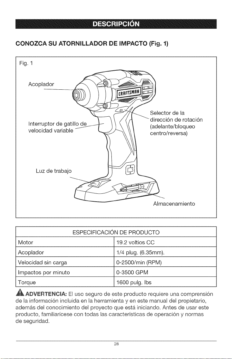
CONOZCA SU ATORNILLADOR DE IMPACTO (Fig. 1)
Fig. 1
Acoplador
Interruptor de gatillo d
velocidad variable
Luz de trabajo
de la
de rotacion
(adelante/bloqueo
centro/reversa)
Almacenamiento
ESPECIFICACION DE PRODUCTO
Motor 19.2 voltios CC
Acoplador 1/4 plug. (6.35mm).
Velocidad sin carga 0-2500/min (RPM)
Impactos por minuto 0-3500 GPM
Torque 1600 pulg. Ibs
A_. ADVERTENCmA: El uso seguro de este producto requiere una comprensi6n
de la informaci6n incluida en la herramienta yen este manual del propietario,
adem&s del conocimiento del proyecto que esta iniciandoo Antes de usar este
producto, familiar[cese con todas las caracteristicas de operaci6n y normas
de seguridad.
28
VELOCIDAD VARIABLE
El gatillo de velocidad vadable ofrece una velocidad mayor con una presi6n
de gatillo mayor y una velocidad menor cuando se presiona el gatillo con
menos fuerza.
ADELANTE/REVERSNCENTRO BLOQUEO
La atornillador de impacto cuenta con un selector de direcci6n de rotaci6n
ubicado sobre el interruptor de gatillo que se utiliza para cambiar la direcci6n de
rotaci6n de la broca. Colocar el interruptor de gatillo en Baposici6n OFF (centro
bloqueo) ayuda a reducir la posibilidad de un arranque accidental cuando no se
encuentra en uso.
LUZ DETRABAJO LED
La luz de trabajo LED, ubicada en el base de Baatornillador de impacto, se
ilumina cuando se presiona el interruptor de gatillo. Esta caracteristica ofrece luz
extra para Iograr una visibilidad mayor.
,_ ADVERTENCIA: Si falta alguna pieza o si alguna pieza esta rota, no trate de
enchufar el cable de energia u operar la perforadora/atornilladora hasta que se
reemplacen las piezas faltantes o rotas. No hacerlo puede provocar una lesion
personal grave.
_, ADVERTENCIA: No trate de modificar esta perforadora/atomilladora o
crear accesorios no recomendados para usar con esta herramienta. Cualquier
alteracion o modificacion constituye un uso indebido y podria provocar una
condicion peligrosa y posibles lesiones graves.
ADVERTENCIA: Para prevenir un arranque accidental que podria provocar
lesiones personales graves, siempre desconecte el paquete de bater[as de la
perforadora./atornilladora cuando cambie las brocas.
DESEMPAQUE
Este producto se ha enviado completamente montado.
• Con cuidado, quite la herramienta y los accesorios de la caja. AsegOrese de
que todos los elementos listados en el paquete esten incluidos.
Inspeccione la herramienta con detenimiento para constatar que no hayan
ocurrido roturas o da_os durante el envio.
No descarte el material de empaque hasta que haya inspeccionado la
herramienta con cuidado y la haya utilizado satisfactoriamente.
Si falta alguna pieza o alguna pieza se encuentra rota, devuelva la
herramienta al lugar de compra.
29
LISTA DE EMPAQUE
Atornillador de impacto, broca (instalada del atornillador de impacto) y manual
del propietario
Este producto acepta paquetes de baterias de ion de litio Craftsman C3 de
19.2V. Para las instrucciones de carga completas, consulte los Manuales del
Operador correspondientes a los paquetes de baterias y cargadores.
A_. ADVERTENCIA: Para evitar un arranque accidental que podr[a provocar
lesiones personales graves, siempre desconecte el paquete de bater[as de
la herramienta cuando coloque piezas, realice ajustes, instale o quite brocas,
efectOe la limpieza o cuando no Io este utflizando.
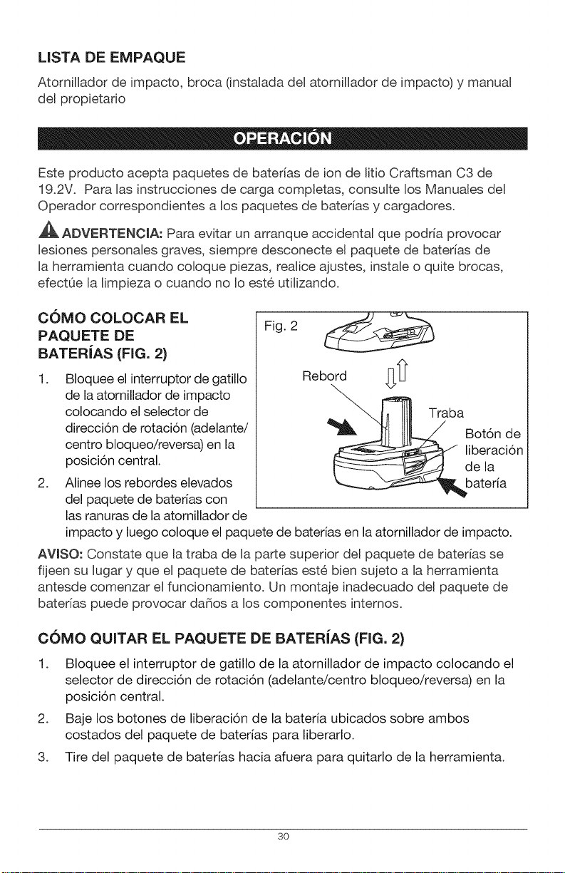
COMO COLOCAR EL
PAQUETE DE
BATER|AS (FIG. 2)
1.
2.
Bloquee el interruptor de gatillo
de la atornillador de impacto
colocando el selector de
direccion de rotacion (adelante/
centro bloqueo/reversa) en la
posicion central.
Alinee los rebordes elevados
del paquete de baterias con
las ranuras de la atornillador de
Fig. 2
Rebord
Traba
impacto y luego coloque el paquete de baterias en la atornillador de impacto.
AVlSO: Constate que la traba de la parte superior del paquete de bater[as se
fijeen su lugar y que el paquete de bater[as este bien sujeto a la herramienta
antesde comenzar el funcionamiento. Un montaje inadecuado del paquete de
batedas puede provocar da_os a los componentes internos.
COMO QUITAR EL PAQUETE DE BATER|AS (FIG. 2)
1. Bloquee el interruptor de gatillo de la atornillador de impacto colocando el
selector de direccion de rotacion (adelante/centro bloqueo/reversa) en la
posicion central.
2. Baje los botones de liberacion de la bateria ubicados sobre ambos
costados del paquete de baterias para liberarlo.
3. Tire del paquete de baterias hacia afuera para quitarlo de la herramienta.
3O
A
A_. ADVERTENCIA: Las herramientas a bater[a siempre se encuentran en
condiciones operativas. Por Io tanto, el selector de direcci6n de rotaci6n
siempre debe estar bloqueado cuando Baherramienta no este en uso o cuando
la Ileve a su lado.
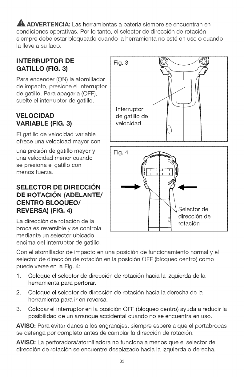
INTERRUPTOR DE
GATILLO (FIG. 3)
Para encender (ON) la atornillador
de impacto, presione el interruptor
de gatillo. Para apagarla (OFF),
suelte el interruptor de gatillo.
VELOCIDAD
VARIABLE (FIG. 3}
El gatillo de velocidad variable
ofrece una velocidad mayor con
Fig. 3
Interruptor
de gatillo de
velocidad
una presi6n de gatillo mayor y
una velocidad menor cuando
se presiona el gatillo con
menos fuerza.
SELECTOR DE DIRECCION
DE ROTACION (ADELANTE/
CENTRO BLOQUEO/
REVERSA} (FIG. 4}
La direcci6n de rotaci6n de Ba
broca es reversible y se controla
mediante un selector ubicado
encima del interruptor de gatillo.
Fig. 4
Selector de
0 direccion de
rotacion
Con el atornillador de impacto en una posici6n de funcionamiento normal y el
selector de direcci6n de rotaci6n en la posici6n OFF (bloqueo centro) como
puede verse en la Fig. 4:
1. Coloque el selector de direccion de rotacion hacia la izquierda de la
herramienta para perforar.
2. Coloque el selector de direccion de rotacion hacia la derecha de la
herramienta para ir en reversa.
3. Colocar el interruptor en la posicion OFF (bloqueo centro) ayuda a reducir la
posibilidad de un arranque accidental cuando no se encuentra en uso.
AVISO: Para evitar da_os a los engranajes, siempre espere a que el portabrocas
se detenga pot completo antes de cambiar la direcci6n de rotaci6n.
AVlSO: La perforadora!atomilladora no funciona a menos que el selector de
direcci6n de rotaci6n se encuentre desplazado hacia la izquierda o derecha.
3i
FRENO EUeCTRICO
Para detener Baperforadora!atornilbdora, libere el interruptor de gatillo y permita
que el portabrocas se detenga per complete. El freno electrico r&pidamente
detiene la rotaci6n del portabrocas. Esta funci6n se activa autom&ticamente
cuando se Bibera el interrupter de gatillo.
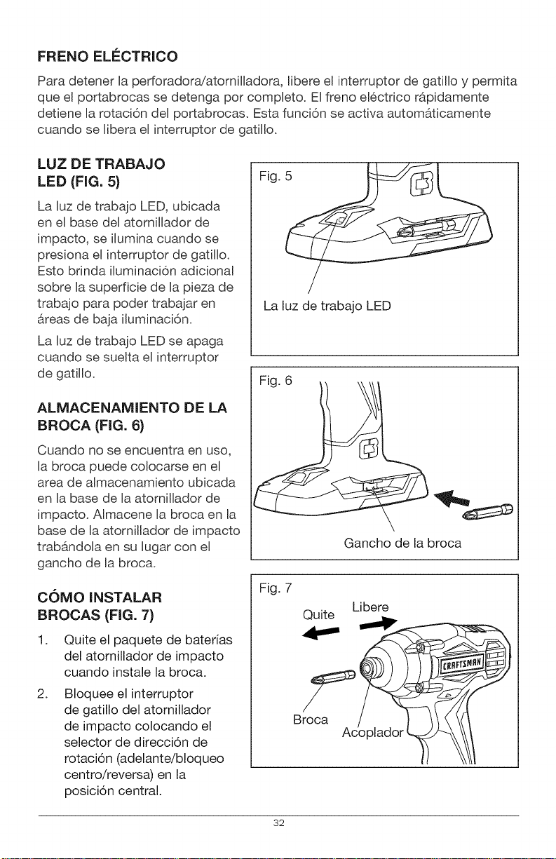
LUZ DE TRABAJO
LEE) (FIG, 5}
La Buzde trabajo LED, ubicada
en el base del atornillador de
impacto, se ilumina cuando se
presiona el interrupter de gatillo.
Esto brinda iluminaci6n adicional
sobre la superficie de la pieza de
trabajo para poder trabajar en
&reas de baja iluminaci6n.
La luz de trabajo LED se apaga
cuando se suelta el interrupter
de gatillo.
ALMACENAMIENTO DE LA
BROCA (FIG. 6}
Cuando no se encuentra en use,
la broca puede colocarse en el
area de almacenamiento ubicada
en la base de la atornilbdor de
impacto. Almacene la broca en la
base de la atornillador de impacto
trab&ndola en su lugar con el
gancho de la broca.
COMO iNSTALAR
BROCAS (FIG. 7)
1. Quite el paquete de baterias
del atornillador de impacto
cuando instale la broca.
2.
Bloquee el interruptor
de gatillo del atornillador
de impacto colocando el
selector de direccion de
rotacion (adelante/bloqueo
centro/reversa) en la
posicion central.
Fig.
La luz de trabajo LED
Fig 6 ___
Gancho de la broca
Fig. 7
Libere
Br_cQuite __I_
32
3. Quite el acoplador del atornillador.
4. Introduzca la broca del atornillador dentro del acoplador.
5. Libere el acoplador.
6. Tire de la broca para asegurar que se halle firme en el acoplador. Puede
haber algo de juego en la broca instalada; esto es normal.
,_, ADVERTENClA: AsegOrese de que la broca este firme en el acoplador antes
de utilizar el atornillador de impacto. Si el acoplador no vuelve a su posici6n
original, la broca no est& bien instalada. Vuelva a intentar hasta que la broca
quede bien instalada y el acoplador retorne a su posicion original. No hacerlo
puede provocar una lesion personal grave.
COMO QUITAR LAS BROCAS (FIG. 7)
1. Quite el paquete de baterias del atornillador de impacto cuando instale
la broca.
2. Bloquee el interruptor de gatillo del atornillador de impacto colocando el
selector de direccion de rotacion (adelante/bloqueo centro/reversa) en la
posicion central.
3. Quite el acoplador del atornillador.
4. Retire la broca.
_, ADVERTENCIA: Utilice guantes protectores cuando quite la broca de la
herramienta, o antes deje que la broca se enfrie. La broca puede estar caliente
despues de un uso prolongado.
PRECAUCION: El atornillador de impacto no est& dise_ado para utilizarse
como un taladro.
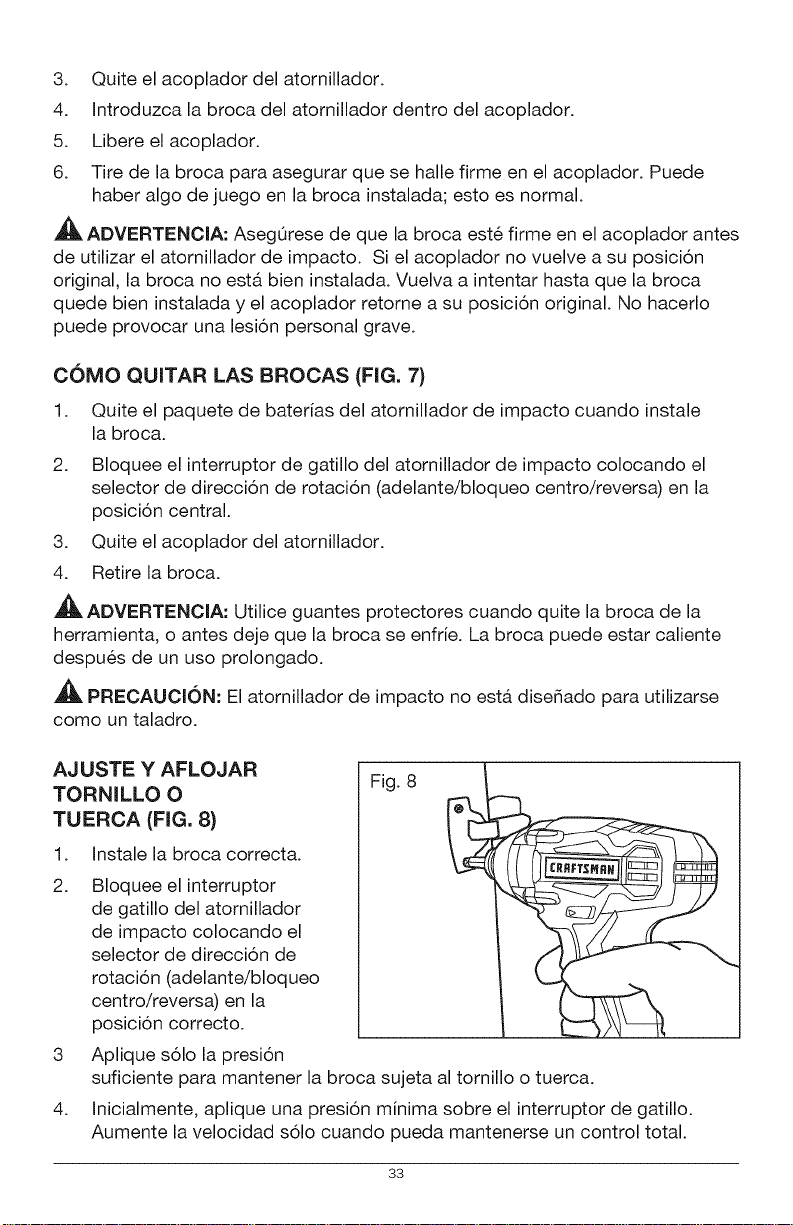
AJUSTE Y AFLOJAR
TORNILLO O
TUERCA (FIG. 8}
1.
2.
3
4.
Instale la broca correcta.
Bloquee el interruptor
de gatillo del atornillador
de impacto colocando el
selector de direccion de
rotacion (adelante/bloqueo
centro/reversa) en la
posicion correcto.
Aplique solo la presion
Fig. 8
suficiente para mantener la broca sujeta al tornillo o tuerca.
Inicialmente, aplique una presion minima sobre el interruptor de gatillo.
Aumente la velocidad solo cuando pueda mantenerse un control total.
33
_IL ADVERTENClA: No ajuste de mAs, ya que la fuerza del atornillador de
impacto puede romper la sujecion. Mantenga el atornillador de impacto en
Angulo recto respecto de la sujecion para no daSar la cabeza de la misma.
_1_ ADVERTENClA: Para evitar una lesi6n personal grave, siempre quite el
paquete de baterias de la herramienta cuando la limpie o realice alguna clase
de mantenimiento.
ADVERTENClA: Siempre utilice gafas de seguridad con protecciones
laterales cuando utilice aire comprimido para limpiar la herramienta. Si durante
la operaci6n se genera mucho polvillo, tambien use una mascara antipolvillo.
MANTENIMIENTO GENERAL
Evite usar solventes cuando limpie piezas pl&sticas. La mayor[a de los pl&sticos
son susceptibles a da_os pot parte de varios tipos de solventes comerciales y
pueden da_arse pot su uso. Utilice pa_os para quitar suciedad, polvillo, aceite,
grasa, etc.
,_IL ADVERTENCIA: No permita bajo ninguna circunstancia que liquido de
frenos, gasolina, productos a base de petr61eo, aceites penetrantes, etc. entren
en contacto con las piezas pl&sticas. Los quimicos pueden da_ar, debilitar o
destruir el plastico, Io que puede provocar una lesion personal grave.
ADVERTENCIA: Cuando realice un mantenimiento, solo utilice piezas de
repuesto identicas. El uso de otras piezas puede generar un riesgo o provocar
da_os al producto. Para garantizar la seguridad y la confiabilidad, todas las
reparaciones deben ser efectuadas por un tecnico calificado.
PROBLEMA CAUSA SOLUCION
El atornillador no
La bateria esta gastada Cargue la bateria
funciona
La broca no puede
instalarse
La manga no se ha
liberado
Libere la manga
La broca no entra en
la manga
AsegOrese de que las
ventilaciones esten
libres de polvillo
y obstaculos
Utilice una adaptador
adecuado
Limpie las ventilaciones.
Sobrecalentamiento No las cubra con las
del motor manos durante el
funcionamiento
34


® Registered Trademark / TMTrademark of KCD IP, LLC in the United States, or Sears Brands, LLC in other countries
® Marca Registrada / TMMarca de FAbdca de KCD IP, LLC en Estados Unidos, o Sears Brands, LLC in otros paises

