FOR INSTALLER ONLY
THIS RANGE IS FOR RESIDENTIAL USE ONLY
INSTALLATION AND SERVICE MUST BE PERFORMED
BY A QUALIFIED INSTALLER.
WARNING:
This appliance has to be installed by a qualified installer.
Improper installation, adjustment, alteration, services, or maintenance can cause
injury or property damage. Consult a qualified installer, service agent, or the gas
supplier.
Never Operate the Top Surface Cooking Section of this Appliance Unattended
•Failure to follow this warning statement could result in fire, explosion, or burn
hazard that could cause property damage, personal injury, or death.
•If a fire should occur, keep away from the appliance and immediately call your fire
department.
DO NOT ATTEMPT TO EXTINGUISH AN OIL/GREASE FIRE WITH WATER.
WARNING: If the information in this manual is not followed exactly, a fire or
explosion may result causing property damage, personal injury or death.
Do not store or use gasoline or other flammable vapors and liquids in the vicinity of this or
any other appliance.
WHAT TO DO IF YOU SMELL GAS
- Do not light any appliance.
- Do not touch any electrical switch.
- Do not use any phone in your building.
- Immediately call your gas supplier from a neighbour’s phone. Follow the gas supplier’s
instructions.
If you cannot reach your gas suppliers , call the fire department.
Installation and service must be performed by a qualified installer service agency or the gas
supplier.
Nuova Lofra S.r.l. reserves the right to modify data and characteristics at any time for technical production needs.
2
WARNING:
- This range can tip. Injury to person could result.
- Install anti-tip device shipped with range.
- See installation Instructions.
IMPORTANT: SAVE FOR LOCAL ELECTRICAL INSPECTOR’S USE.
READ AND SAVE THERE INSTRUCTIONS FOR FUTURE REFERENCE.
OBSERVE ALL GOVERNING CODES AND ORDINANCES.
WARNING:
A child or adult can tip the range and be killed.
Installing the anti-tip device to the structure and/or the appliance.
Engage the range to the anti-tip device by using the four supplied
screws.
Re-engaged the anti-tip device if the range is moved.
See installation instructions for details.
Failure to do so can result in death or serious burns to children or
adults.
3
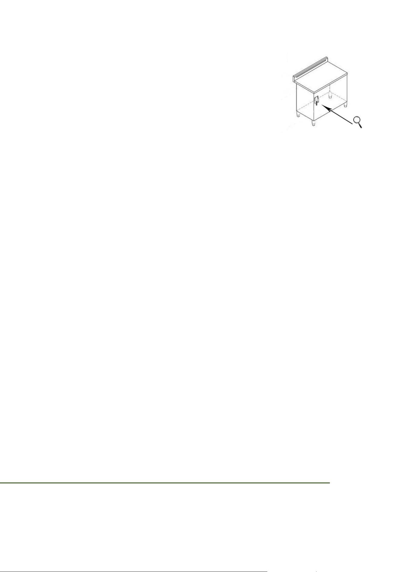
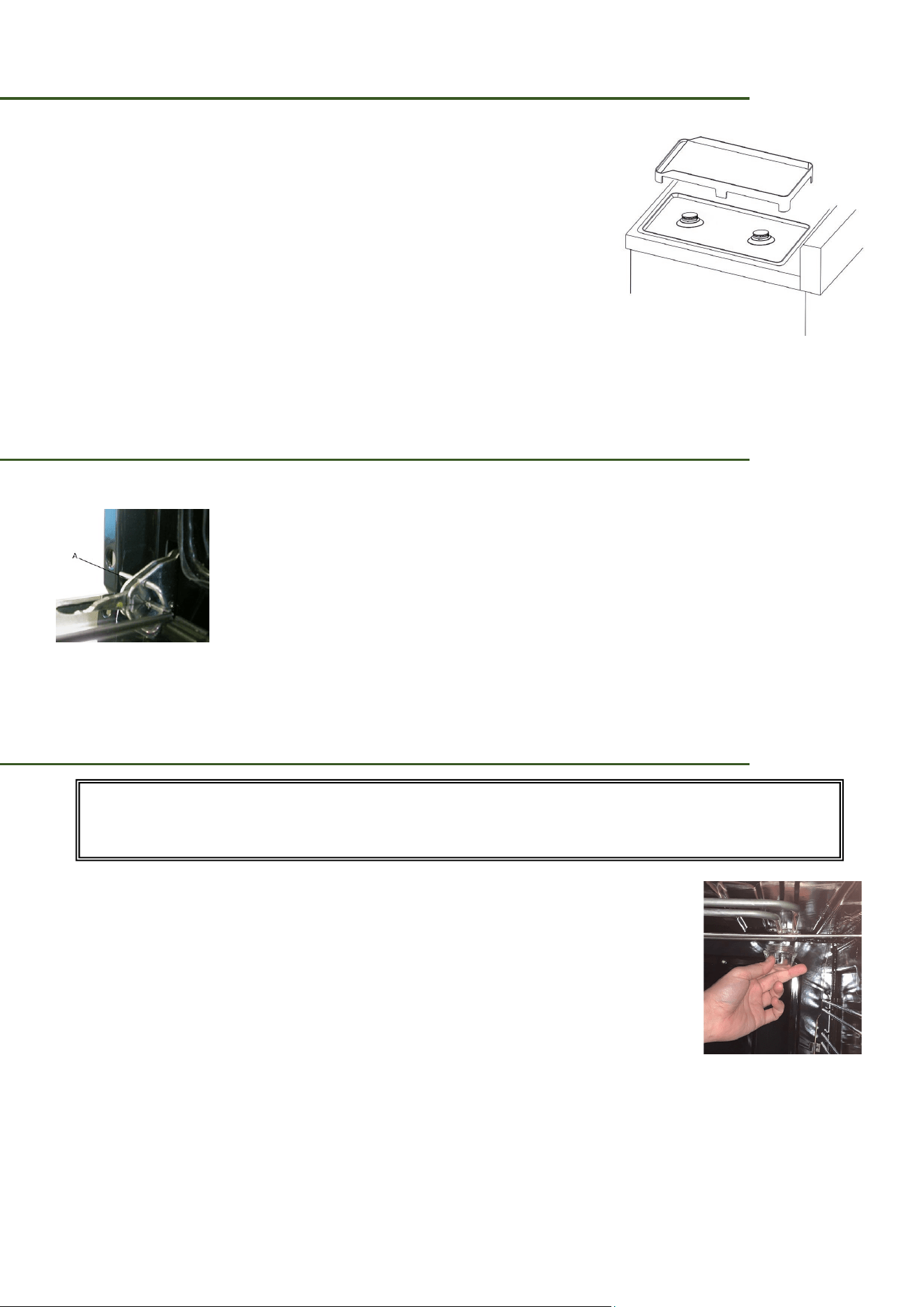
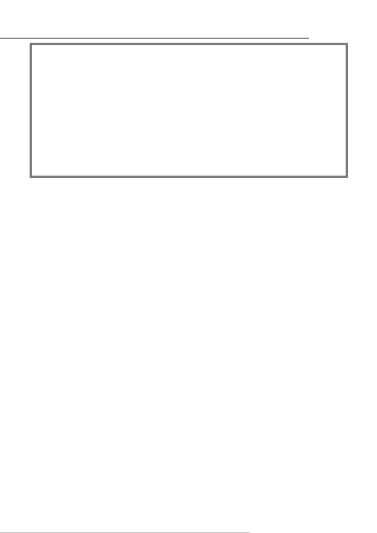
CHECKING THE ANTI TIP DEVICE
To check the installation of the anti-tipping safety system, we
recommend that you view the installation of the bracket under
the kitchen (in the visible part between the feet, see illustration).
IMPORTANT - PLEASE READ AND FOLLOW
Before beginning, please read these instructions completely and carefully.
Do not remove permanently affixed labels, warnings, or plates from the product. This
may void the warranty
Please observe all local and national codes and ordinances.
Please ensure that this product is properly grounded.
The installer should leave these instructions with the consumer who should retain for
local inspector’s use and for future reference.
For an installation at altitudes above 2000 ft (610 mt) contact the Service Centre.
IMPORTANT INSTRUCTION
• To check the installation of the anti-tipping safety system, we recommend that you view
the installation of the bracket under the kitchen (in the visible part between the feet,
see illustration).
• Installation must conform with local codes or in the absence of codes, the National Fuel
Gas Code ANSIZ223.1/NFPA 54- Iatest edition. Electrical installation must be in
accordance with the National Electrical Code, ANSI/NFPA70 - latest edition and/or local
codes.
IN CANADA:
The installation must conform with local codes or, in the absence of local codes, with
the Natural Gas Propane Installation Code, CSA B149.1.
GENERAL INFORMATION
1. Installation must conform with local codes or, in the absence of local codes, with the
National Fuel Gas Code, ANSI Z223.1-Latest Edition.
4
2. Installation in manufactured (mobile) home: installation must conform with the
Manufactured Home Construction and Safety Standard, Title 24 CFR, Part 3280 [formerly
the Federal Standard for Mobile Home Construction and Safety, Title 24, HUD (Part 280)]
or, when such standard is not applicable, the Standard for Manufactured Home
Installations, ANSI/NCSBCS A225.1, or with local codes where applicable.
3. Installation in Recreational Park Trailers: installation must conform with state or other
codes or, in the absence of such codes, to the Standard for Recreational Park Trailers,
ANSI A119.5.
The pressure stated shall be at least 1 in wc (249 Pa) above the manufacturer’s specified
manifold pressure.
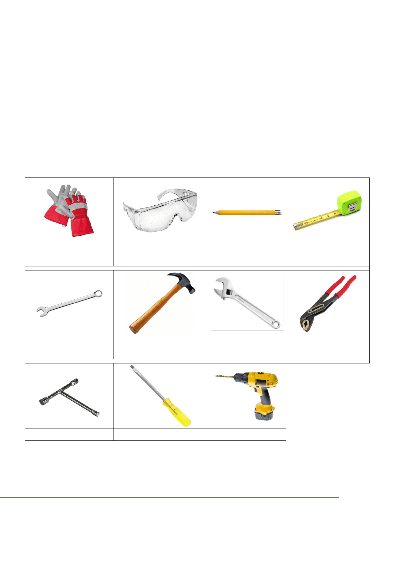
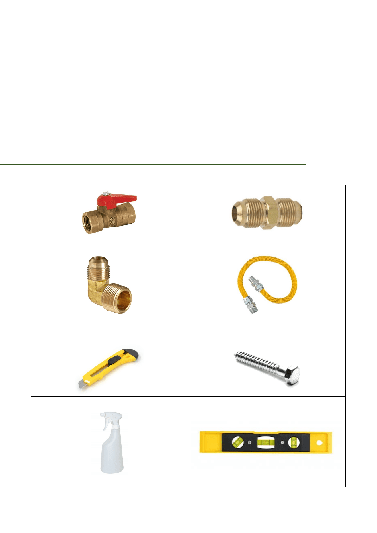
TOOLS NEEDED FOR INSTALLATION (not supplied with the appliance)
Suitable protective
gloves
Protective glasses Pencil Tape measure
2 - Wrench Hammer
Adjustable
wrench
Adjustable pliers
T – handle wrench Screwdriver Drill
IMPORTANT NOTES TO THE INSTALLER
1. Read all instructions contained in these installation instructions before installing range.
5
2. Remove all packing material from the oven and the drawer compartments before
connecting the gas and electrical supply to the range.
3. Observe all governing codes and ordinances.
4. Be sure to leave these instructions with the consumer.
5. Installation of this appliance requires basic mechanical skills.
6. Proper installation is the responsibility of the installer.
7. Product failure due to improper installation is not covered under the Warranty.
To promote safety and minimize problems, read this manual thoroughly before starting the
installation. Leave this manual with the user.
Write the appliance’s model/serial numbers in this manual for service/maintenance
reference.
The user have to keep this manual for personal reference and for that of inspectors, service
personnel, etc.
The appliance should not be installed with a ventilation system that blows air downward
toward the appliance. This type of ventilation system may cause ignition and combustion
problems with the gas cooking appliance resulting in personal injury or unintended
operation.
An air curtain or other overhead range hood, which operates by blowing a downward airflow
onto a range, shall not be used in conjunction with a range.
CAUTION:
Cold temperature can damage the electronic control.
When using the appliance for the first time, or when the
appliance has not been used for an extended period, be
certain the unit has been in temperatures above 32°F
(0°C) for at least 3 hours before turning on the power to
the appliance.
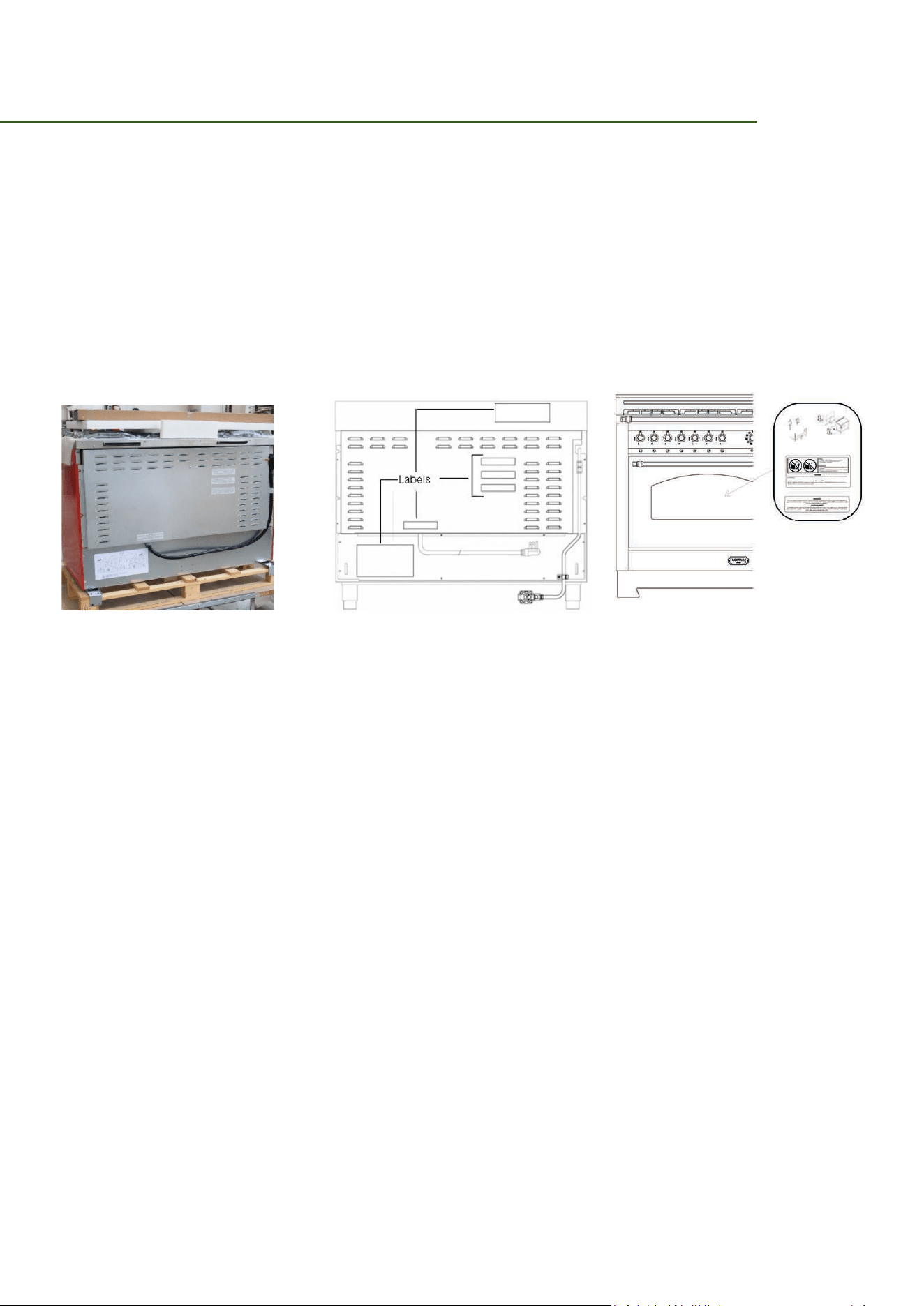
CUSTOMER SERVICE INFORMATION
The serial number can be found on the inner side of door trim.
IMPORTANT SAFETY INSTRUCTIONS
• Make sure the wall coverings around the range can withstand the heat generated by
the range.
Before installing the range in an area covered with linoleum or any other synthetic
floor covering, make sure the floor covering can withstand heat at least 90°F above
room temperature without shrinking warping or discolouring. Do not install the range

6
over carpeting unless you place an insulating pad or sheet of ¼ (0,6 cm) thick plywood
between the range and carpeting.
• Do not obstruct the flow of combustion air at the oven vent nor around the base or
beneath the lower front panel of the range. Avoid touching the vent openings or
nearby surfaces as they may become hot while the oven is in operation. This range
requires fresh air for proper burner combustion.
• If the range is pulled out away from the wall for any reason, make sure the anti-tip
device is reengaged after the range has been pushed back into place.
• Learn where and how to shut off the valve that feeds gas to the product.
• Do not let children sit/stand on the product or play with any of its parts. Do not leave
children unattended in the kitchen when the product is in use.
• Do not keep objects of interest to children on or around the product.
• Remove all packaging before operating the product to keep this material from catching
fire. Keep all packaging away from children. Properly dispose of packaging as soon as
the product is unpacked.
• Do not operate the product if it is damaged in any way, if it malfunctions, or is missing
parts.
• Do not use the product as a space heater. This product is to be used for cooking
purposes only.
• Do not use oven cleaners or oven liners in or around any part of the oven.
• Do not use the product to heat unopened food containers.
• Do not strike the oven glass.
• When disposing of the range, cut off the power cord and remove the door.
• Unplug the product before service/maintenance.
WARNING:
NEVER use this appliance as a space heater to heat or warm
the room. Doing so may result in carbon monoxide poisoning
and overheating of the oven.

7
FIRE SAFETY
• Do not store/place/use combustible materials (e.g., paper, plastic, pot holders, linens,
gasoline, alcohol) near the product.
• Do not douse a grease fire with water. Instead, turn off the heat source, and smother
the fire with a tight-fitting lid, or use a multi-purpose, dry-chemical or foam
extinguisher.
• If a grease fire should occur in the oven, turn off the oven by putting the handle in the
OFF position.
• Do not wear loose fitting or hanging garments while using the product.
• Use only dry potholders: moist or damp potholders on hot surfaces may result in
burns from steam. Do not let potholder touch hot heating elements. Do not use a
towel or other bulky cloth.
• Do not let potholders or other flammable material touch a heating element. Do not use
a towel or other bulky cloth item as a pot holder.
• Use proper pan size: this appliance is equipped with one or more surface units of
different size. Select utensils having flat bottoms large enough to cover the surface
unit-heating element. The use of undersized utensils will expose a portion of the
heating element to direct contact and may result in ignition of clothing. Proper
relationship of utensil to burner will also improve efficiency.
• Glazed cooking utensils: only certain types of glass, glass/ceramic, ceramic,
earthenware, or other glazed utensils are suitable for range-top service without
breaking due to the sudden change in temperature.
• Never leave surface units unattended at high heat settings: broilover causes smoking
and greasy spillovers that my ignite.
• Do not soak removable heating elements: heating elements should never be immersed
in water.
• Keep oven vent ducts unobstructed, to avoid grease build up, regularly clean the vents.
• Use care when opening door: let hot air or steam escape before removing or replacing
food.
• Keep the oven door closed until the fire goes out. If necessary, use a multipurpose dry
chemical or foam-type fire extinguisher.
• Do not heat unopened food containers: build – up of pressure may cause container to
burst and result in injury.

8
GAS SAFETY
If you smell gas:
• Close the valve and do not use the product.
• Do not light a match, candle, or cigarette.
• Do not turn on any gas or electric appliances.
• Do not touch any electrical switch or plug in a power cord.
• Do not use any phone in your building.
• Evacuate everyone from the building.
• Immediately call your gas supplier from a neighbor’s phone. Follow the gas supplier’s
instructions.
• If you cannot reach your gas supplier, call the fire department.
• Checking for gas leaks
• Leak-testing the appliance must be done according to the manufacturer’s
instructions. Do not use a flame to check for gas leaks. Use a brush to spread a soap-
and-water solution around the area you are checking. If there is a gas leak, small
bubbles will appear in the solution. When not sure, call for professional help.
• The appliance must be isolated from the gas supply piping system by closing its
individual manual shut-off valve during any pressure testing of the gas supply piping
system at test pressures equal to or less than ½ psi (3.5 KPa).
• Do not attempt to operate the oven during a power failure.
ELECTRICAL AND GROUNDING SAFETY
• Do not use an adapter or an extension cord.
• Do not use a damaged power plug, power cord, or loose power outlet.
• Do not modify the power plug, cord, or outlet.
• Do not put a fuse in a neutral or ground circuit.
• Do not connect the ground wire to plastic plumbing lines, gas lines, or hot water pipes.

9
• This product must be grounded. If the range malfunctions or breaks down, grounding
reduces the risk of electric shock by providing a safe path for the current. This range's
power cord has a grounding plug, which must be firmly plugged into an outlet that is
properly installed and grounded according to local regulations. If you are not sure your
electrical outlet is properly grounded, have it checked by a licensed electrician.
• The range is supplied with a 4-pronged grounded plug. This cord must be plugged into
a mating, grounded 4-prong outlet that meets all local codes and ordinances.
• The product owner shall ensure that the proper electrical service is provided for the
product.
INSTALLATION SAFETY
• This product should be installed and properly grounded by a qualified installer, as
specified in the Installation Instructions. Adjustments and service should be performed
only by qualified gas range installer or service technician.
• Do not try to service/modify/replace the product or any part of it unless specifically
recommended in this manual. All other service should be performed by a qualified
technician.
• Use only new, flexible connectors when installing the product.
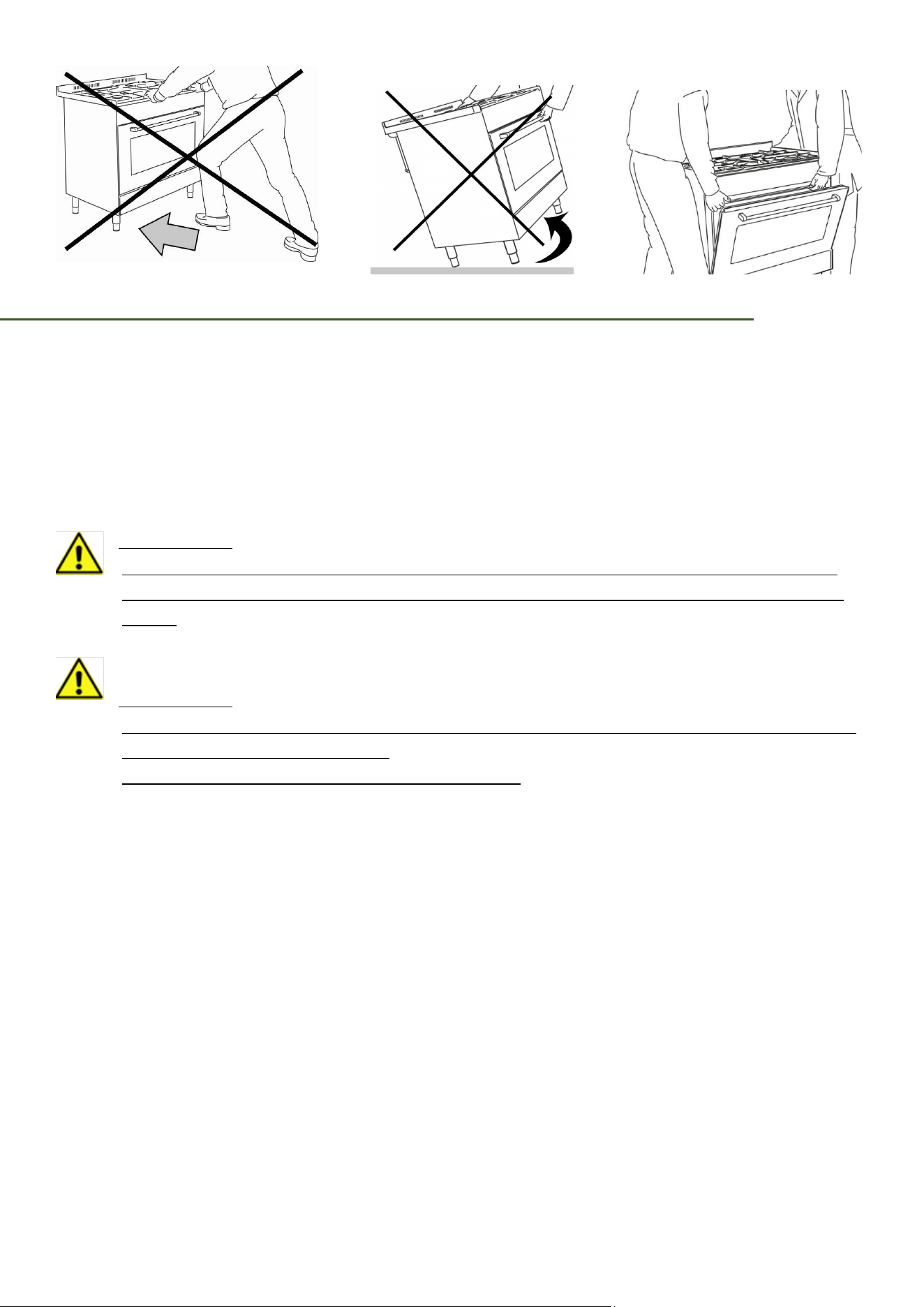
• Due to the size and weight of the range, have two or more people move the range.
• Remove all tape and packaging materials.
• Make sure no parts came loose during shipping.
• After unpacking the product, remove all accessories from inside and around it.
(Cautiously handle the heavy grates).
• Make sure the product is correctly installed/adjusted by a qualified service technician
or installer for the type of gas (natural or Propane) you will use. For the range to use
Propane gas, the installer must replace every surface burner orifices with the provided
Propane orifice set, and reverse the GPR adapter. These adjustments must be made by
a qualified technician according to manufacturer instructions and local regulations. The
qualified agency performing this work shall be responsible for the gas conversion.
LOCATION SAFETY
• This range is for indoor household use only. Do not install the range outdoors or
anywhere that it will be exposed to weather/water or wind/ strong drafts.

10
• Select a level, well-constructed floor that can support the range’s weight. Synthetic
flooring, such as linoleum, must withstand 180 °F (82 °C) temperatures without
shrinking, warping, or discolouring. Do not install the range directly over interior
kitchen carpeting unless a sheet of . inch plywood or a similar insulator is placed
between the range and carpeting.
• Do not hang paper blinds on a window near the range; do not hand long curtains that
could be blown over/onto the range.
• For proper ventilation, the range needs sufficient space below and all around the
chassis. Vents in the chassis exhaust heat and fumes so the range can operate
properly.
• Make sure the wall coverings around the range can withstand heat up to 194 °F (90 °C)
generated by the range.
• Cabinet storage above the surface of the range should be avoided. If cabinet storage
above the range is necessary: allow a minimum clearance of 30 inches (76.2 cm)
between the cooking surface and the bottom of cabinets; or install a range hood that
projects horizontally a minimum of 5 inches (12.7 cm) beyond the bottom of the
cabinets.
COOKTOP SAFETY
• Before igniting, make sure all burner caps are properly in place and all burners are
level.
• Make sure all burners are OFF when not in use.
• Do not leave burners unattended on medium or high heat settings.
• When you set a burner to simmer, do not turn the knob quickly. Make sure the flame
stays on.
• If ignition fails, turn the knob to OFF, and wait a few minutes for the gas to dissipate.
• Do not place any objects other than cookware on the cooktop.
• Before removing or changing cookware, turn off the burners.
• Remove food and cookware immediately after cooking.
• Make sure all cooktop burners are off and all surfaces have completely cooled before
removing the grates and disassembling the burners.
• Before self-cleaning the oven: remove broiler pan and other utensils.
• After cleaning the burner head, make sure it is completely dry before re-assembling.

11
• To avoid carbon monoxide poisoning, do not pour water or other liquids into the
cooktop during cleaning.
• Do not clean door gasket: the door gasket is essential for a good seal. Care should be
taken not to rub, damage, or move the gasket.
• Do not use oven cleaners: no commercial oven cleaner or oven liner protective coating
of any kind should be used in or around any part of the oven.
• Clean only parts listed in manual.
• Select cookware that is designed for cooktops and that is large enough to cover the
grates. Burner flames should not extend beyond the bottom of the cookware.
• To avoid cookware discoloration, deformity, and/or carbon monoxide poisoning, do
not use cookware that is exceedingly larger than the grate.
• Do not use aluminium foil to line the grates or any part of the cooktop.
• Always use a minimum amount of oil for any type of frying. Always thaw food before
frying, and do not frying food that is overly cold or that has clumps of ice attached to it.
• When frying, always heat the oil slowly, and monitor the oil as it heats. When frying
foods at high heat, monitor the oil throughout the cooking process. If combining fats or
oils for frying, mix them together before heating. Stand at a safe distance while frying
to avoid hot spatter.
• Use a deep-fry thermometer when possible to avoid heating the oil beyond its smoke
point. (Know the smoke point of the oil you are using.)
• Always let the oil/fat in the cookware to cool to room temperature before moving the
cookware.
• To avoid delayed-eruptive boiling, let hot oil/fat stand at least 20 seconds after turning
off the burner so the temperature can stabilize. In the event of scalding, follow these
first-aid instructions:
1. Immerse the scaled area in cool or lukewarm water for at least 10 minutes.
2. Do not apply any creams, oils, or lotions.
3. Cover with a clean, dry cloth.
OVEN SAFETY
• Do not use the oven for non-cooking purposes such as drying clothes or storage. Use
the oven for cooking purposes only.
• Do not leave plastic items inside the oven.
12
• Do not use aluminium foil or foil liners anywhere in the oven. Do not use aluminium
foil or like material to cover any holes or passages in the oven bottom or to cover an
oven rack.
• When repositioning the oven racks, make sure the oven is completely cool.
• Make sure the oven racks are placed on the same level on each side.
• Do not damage, move, or clean the door gasket.
• Stand away from the oven when opening the oven door.
• To avoid damaging the burner control knobs or oven control, always bake and/or broil
with the oven door closed.
• Do not broil meat too close to the broil element. Trim excess fat from meat before
cooking.
• When using cooking or roasting bags in the oven, follow the manufacturer’s
directions.
• Keep the oven free from grease build up.
• Do not spray water on the oven glass while the oven is on or just after you have turned
it off.
• Do not use harsh abrasive cleaners or sharp metal scrapers to clean the oven door
glass. They can scratch the surface which may result in the glass shattering.
CAUTION:
• Do not attempt to operate the oven during a power failure.
• If the power fails, always turn the oven off. If the oven is not turned off and the power
returns, the oven may begin to operate again. Food left unattended could catch fire or
spoil.
CAUTION:
• Stepping, leaning or sitting on the door or drawers of this range can result in serious
injuries and can also cause damage to the range.
WARNING:
Never leave children alone or unattended in the area where
an appliance is in use. As children grow, teach them the
proper, safe use of all appliances. Never leave the oven door
open when the range is unattended.
13
• Do not store items of interest to children in the cabinets above the range. Children
could be seriously burned climbing on the range to reach items.
• To eliminate the need to reach over the surface burners, cabinet storage space above
the burners should be avoided.
• Adjust surface burner flame size so it does not extend beyond the edge of the cooking
utensil. Excessive flame is hazardous.
• Do not use the oven as a storage space. This creates a potentially hazardous situation.
• Never use your range for warming or heating the room. Prolonged use of the range
without adequate ventilation can be dangerous.
• Do not store or use gasoline or other flammable vapors and liquids near this or any
other appliance. Explosions or fires could result.
• In the event of an electrical power outage, the surface burners can be lit manually.to
light a surface burner, hold a lit match to the burner head and slowly turn the Surface
Control knob to LITE. Use caution when lighting surface burners manually.
• Reset all control to the “off“ position after using a programmable timing operation.
To avoid breakage: Do NOT handle or manipulate the unit by the cooktop.
Electrical and gas equipment with moving parts can be dangerous. The important safety
instructions in this manual are intended to minimize the risk of property damage, personal
injury, and death. Be sure to read them.
Keep this manual in a handy place so you can refer to it as needed.
CABINET CONSTRUCTION
Caution: To eliminate the risk of burns or fire by reaching over heated surface units, do not
have cabinet storage space above the range.
COUNTERTOP PREPARATION
The cooktop sides of the range fit over the cut-out edge of your countertop.
Countertop must be level. Place a level on the countertop, first side to side, then front to
back. If the countertop is not level, the range will not be level. The oven must be level for
satisfactory baking results. Cooktop sides of range fit over edges of countertop opening.
REPLACEMENT PARTS
Only authorized replacement parts may be used in performing service on the range.
Replacement parts are available from factory authorized parts distributors. Contact the
nearest parts distributor in your area.
14
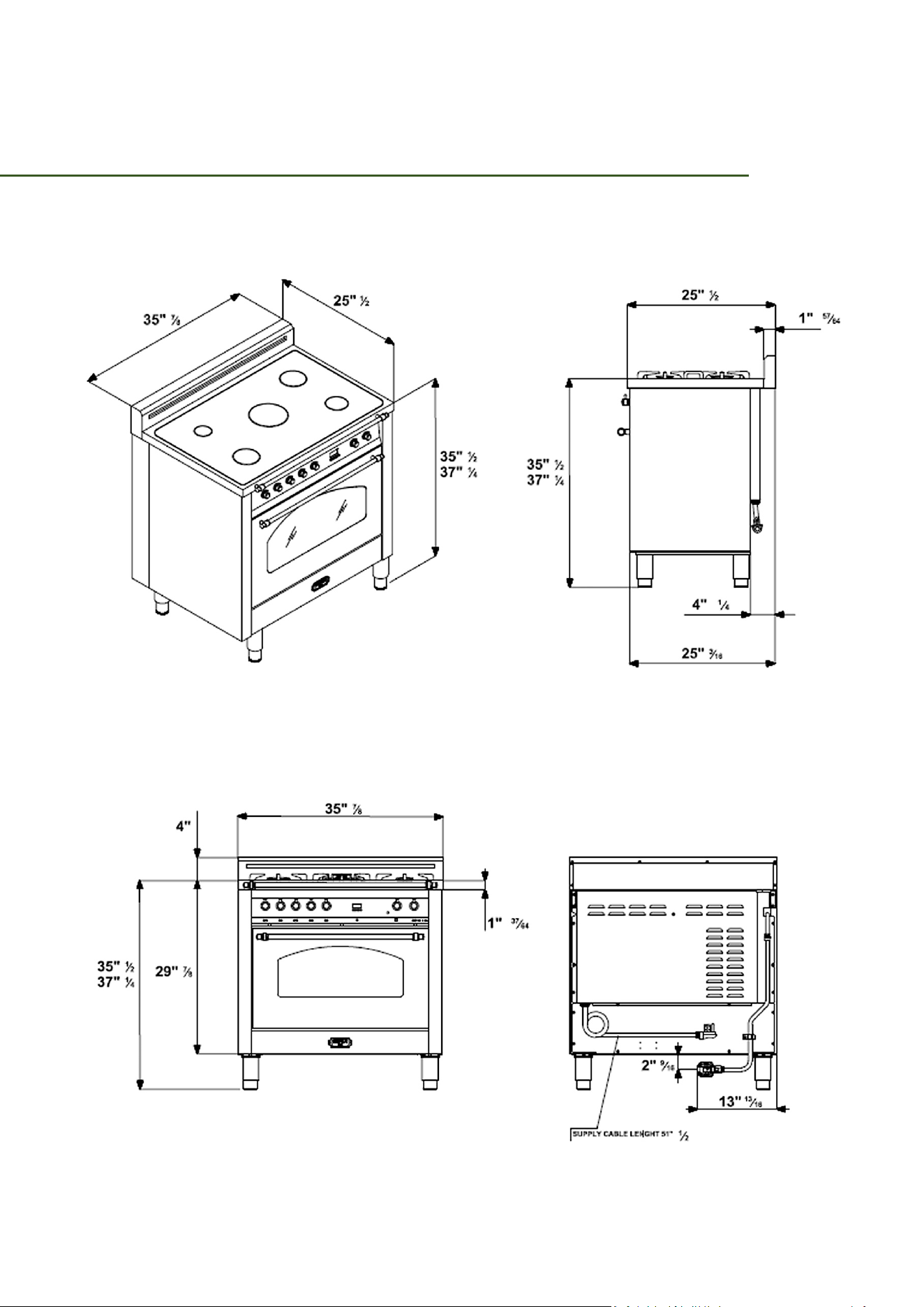
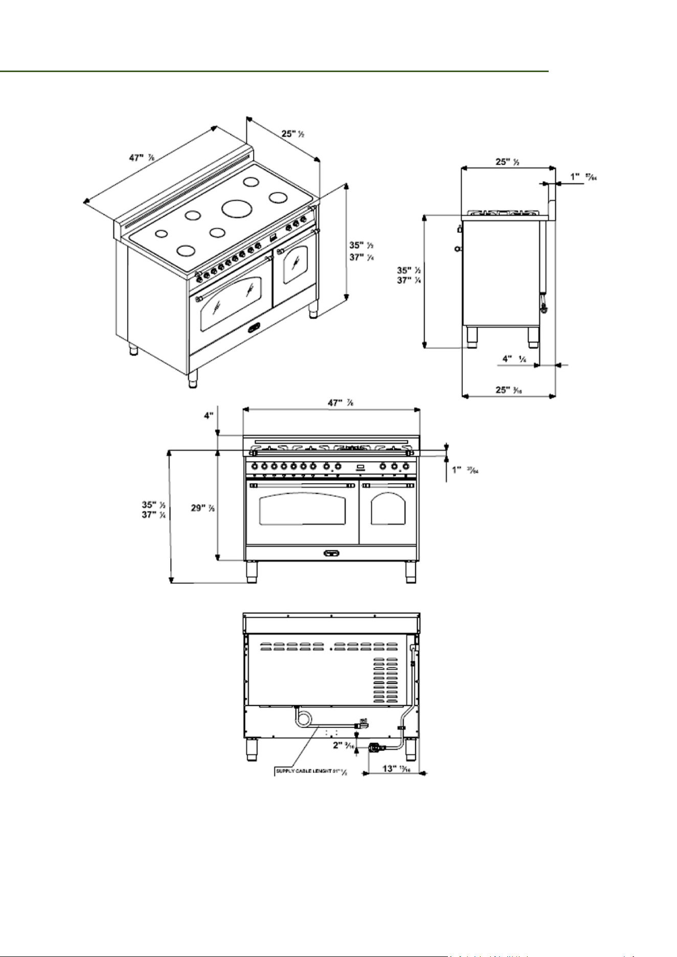
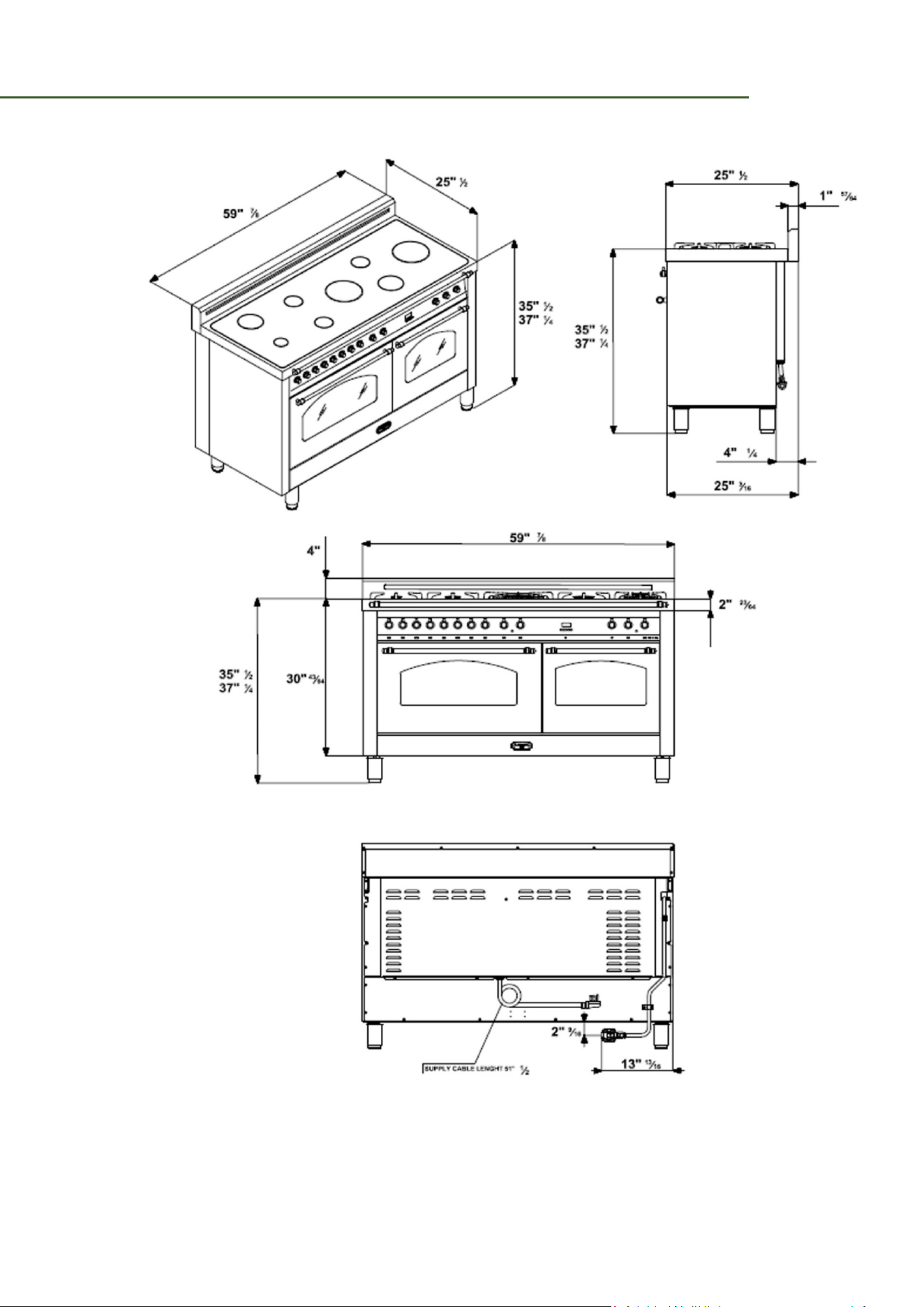
PRODUCT SPECIFICATION
NOTE: do not pinch the power supply cord or the flexible gas conduit
between the range and the wall.
Do not seal the range to the side cabinets.
For all other information about the appliance, see the labels on the back of the appliance.
15
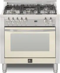
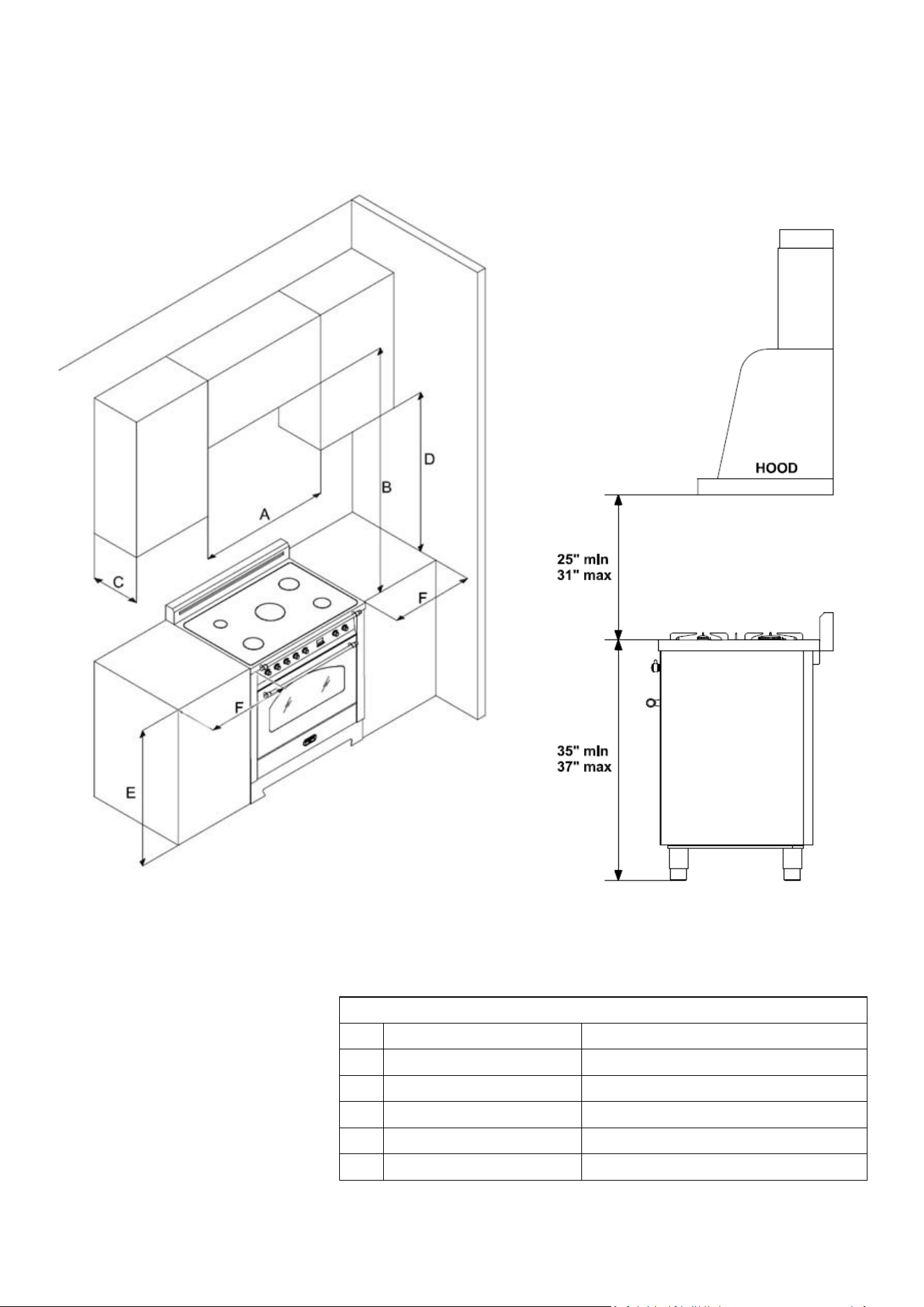
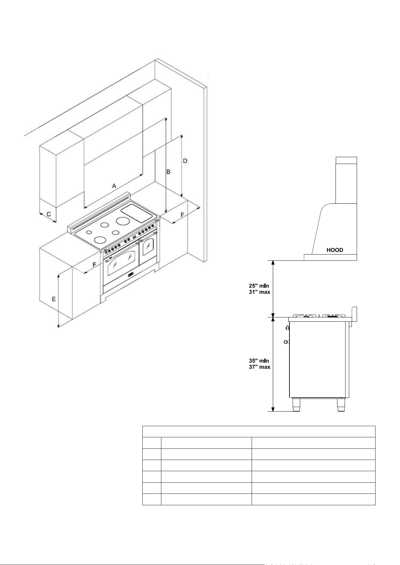
30” COOKER
• 30 in (76.2 cm) minimum clearance between the top of the cooking surface and the bottom of an unprotected wood or
metal cabinet; or If no 30 in (76.2 cm) minimum clearance, 24 in (61 cm) minimum when the bottom of the wood or
metal cabinet is protected by not less than 0.25 in (0.64 cm) flame-retardant millboard covered with not less than no.
28 MSG sheet steel, 0.015 in (0.038 cm) stainless steel, 0.024 in (0.061 cm) aluminium, or 0.020 in (0.051 cm) copper.
• 6 in (45.7 cm) minimum between the countertop and the adjacent cabinet bottom.
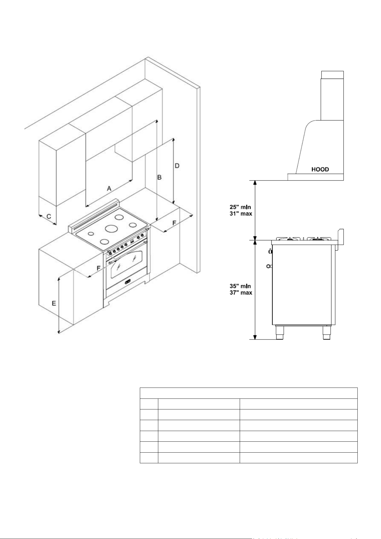
16
Zero clearance between
adjacent combustible
construction below the
countertop surface and the
back and sides of the
appliance.
MEASURES FOR BUILT - IN
A
30”
76,20 cm
B
Min. 25” – Max. 31”
Min. 63,50 cm – Max. 78,74 cm
C
Max. 13”
Max. 33,00 cm
D
Min. 18” Min. 45,70 cm
E
35” ½ or 37” ¼
90,20 cm or 94,60 cm
F
Min. 6”
Min. 15,20 cm
17
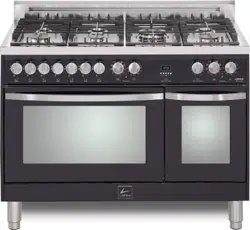
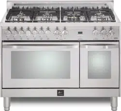
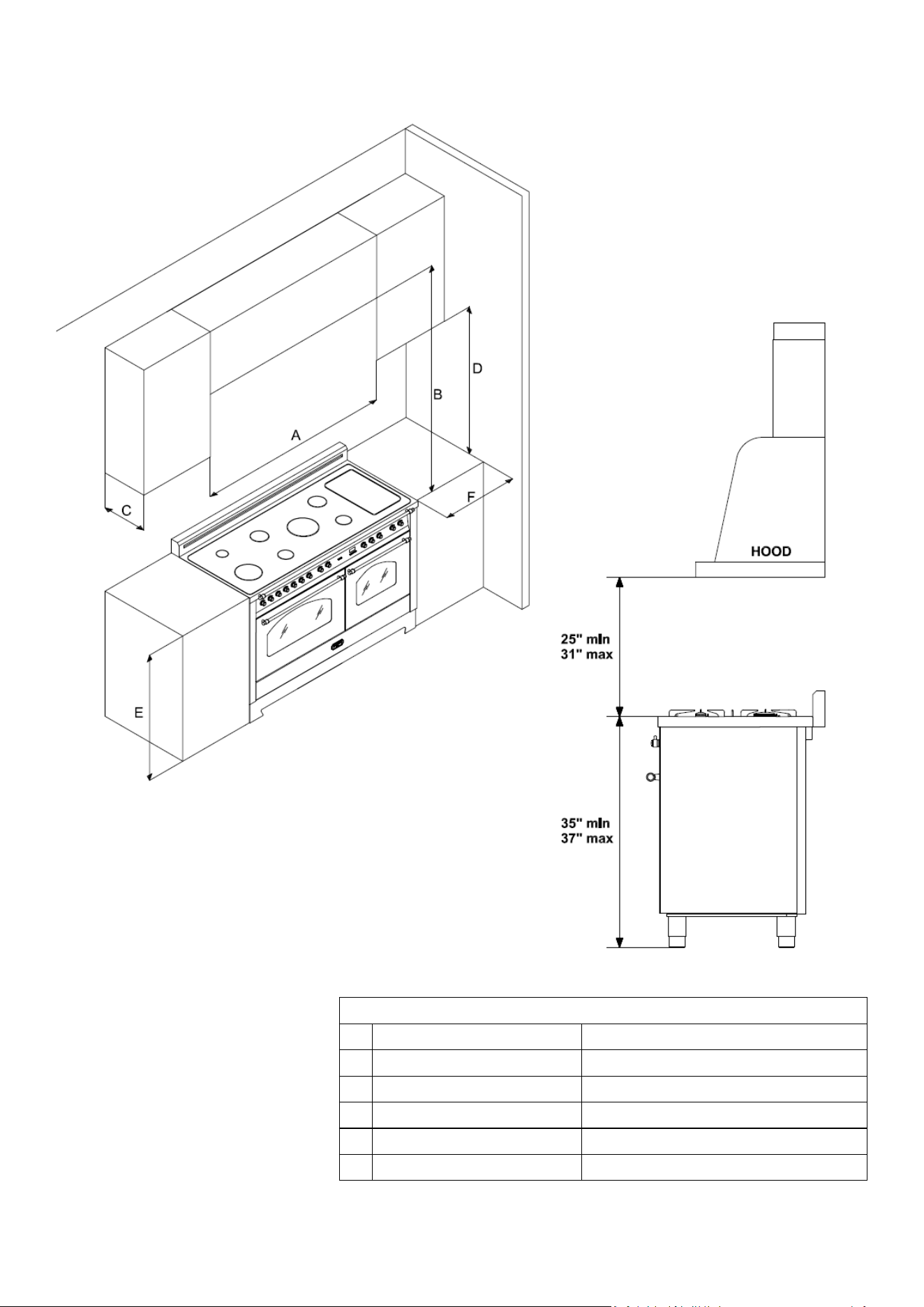
36” COOKER
• 30 in (76.2 cm) minimum clearance between the top of the cooking surface and the bottom of an unprotected wood or
metal cabinet; or If no 30 in (76.2 cm) minimum clearance, 24 in (61 cm) minimum when the bottom of the wood or
18
metal cabinet is protected by not less than 0.25 in (0.64 cm) flame-retardant millboard covered with not less than no.
28 MSG sheet steel, 0.015 in (0.038 cm) stainless steel, 0.024 in (0.061 cm) aluminium, or 0.020 in (0.051 cm) copper.
• 6 in (45.7 cm) minimum between the countertop and the adjacent cabinet bottom.
Zero clearance between
adjacent combustible
construction below the
countertop surface and the
back and sides of the
appliance.
MEASURES FOR BUILT - IN
A
36” 91,50 cm
B
Min. 25” – Max. 31”
Min. 63,50 cm – Max. 78,74 cm
C
Max. 13”
Max. 33,00 cm
D
Min. 18”
Min. 45,70 cm
E
35” ½ or 37” ¼
90,20 cm or 94,60 cm
F
Min. 6”
Min. 15,20 cm
19
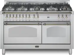
48” COOKER
• 30 in (76.2 cm) minimum clearance between the top of the cooking surface and the bottom of an unprotected wood or
metal cabinet; or If no 30 in (76.2 cm) minimum clearance, 24 in (61 cm) minimum when the bottom of the wood or
metal cabinet is protected by not less than 0.25 in (0.64 cm) flame-retardant millboard covered with not less than no.
28 MSG sheet steel, 0.015 in (0.038 cm) stainless steel, 0.024 in (0.061 cm) aluminium, or 0.020 in (0.051 cm) copper.
• 6 in (45.7 cm) minimum between the countertop and the adjacent cabinet bottom.
20
Zero clearance between
adjacent combustible
construction below the
countertop surface and the
back and sides of the
appliance.
MEASURES FOR BUILT - IN
A
48”
121,90 cm
B
Min. 25” – Max. 31”
Min. 63,50 cm – Max. 78,74 cm
C
Max. 13” Max. 33,00 cm
D
Min. 18” Min. 45,70 cm
E
35” ½ or 37” ¼
90,20 cm or 94,60 cm
F
Min. 6”
Min. 15,20 cm
21
60” COOKER
• 30 in (76.2 cm) minimum clearance between the top of the cooking surface and the bottom of an unprotected wood or
metal cabinet; or If no 30 in (76.2 cm) minimum clearance, 24 in (61 cm) minimum when the bottom of the wood or
metal cabinet is protected by not less than 0.25 in (0.64 cm) flame-retardant millboard covered with not less than no.
28 MSG sheet steel, 0.015 in (0.038 cm) stainless steel, 0.024 in (0.061 cm) aluminium, or 0.020 in (0.051 cm) copper.
• 6 in (45.7 cm) minimum between the countertop and the adjacent cabinet bottom.
22
Zero clearance between
adjacent combustible
construction below the
countertop surface and the
back and sides of the
appliance.
MEASURES FOR BUILT - IN
A
60”
152,40 cm
B
Min. 25” – Max. 31”
Min. 63,50 cm – Max. 78,74 cm
C
Max. 13” Max. 33,00 cm
D
Min. 18”
Min. 45,70 cm
E
35” ½ or 37” ¼
90,20 cm or 94,60 cm
F
Min. 6”
Min. 15,20 cm
23
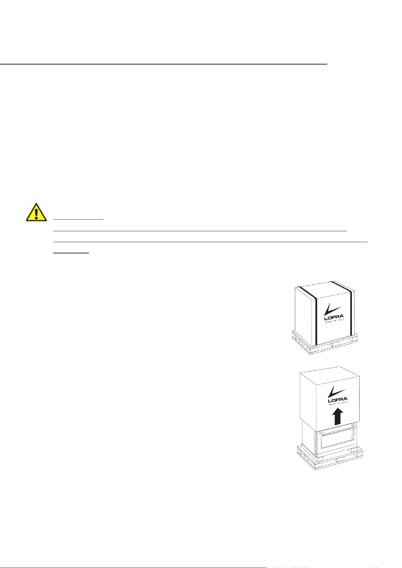
REMOVE PACKAGING
1. REMOVE THE OUTER PACKAGE
Cut the metal banding and lift the carton straight up.
Locate the two runner strips from the top of the packaging. These strips will be used to
protect the kitchen floor during installation.
Remove grill/griddle covers, grill grate and burner grates.
Lift out cast-iron griddle flue cover, grease troughs and pads.
Cut the ties holding the grill grate to the grill frame.
Lift off burner caps, remove foam pad, and then lift off burner heads, and remove foam pad.
Open oven door(s) and remove packaging.
Remove shelf holding broiler pan, tape, literature package, shelf lubricant and probe.
CAUTION:
Doors and passageways leading to the installation location require at least 32”
opening. If the opening is less than 32”, the oven door(s) and control knobs must be
removed.
2. REMOVE THE OVEN DOOR(S) ONLY IF NECESSARY
To move the range through the doorways. To prevent damage to
the slides of the range, it will be necessary to pad the corners
beneath the straps on the hand-truck.
To remove the oven door(s):
• Fully open the door
• Each hinge has a hinge latch. Close the hinge latch down
against the doorframe.
• Firmly gasp the door at the top sides.
• Close the door to the near vertical position
• Lift the door up and pull straight out.
• Remove the control knobs by pulling them straight out.
3. MOVE THE RANGE INDOORS
1. Tilt the range forward on the skid
2. Lift the toe kick out of the foam base
3. Drive the blade of the hand-truck beneath the foam block
4. Attach the hand-truck straps around the unit.
24
IMPORTANT: place the hand-truck straps below the oven door handles. To avoid damaging
the side panels place a pad between the hand-truck and the range.
5. Tilt the range to lower the hand-truck wheels off the skid.
6. Place the appliance runners on the floor at the left and right sides in front of the
opening.
IMPORTANT: the runners provide a surface for rolling the range into the final position and
will protect the floor finish. The runners must be removed before levelling the range.
7. Move the range indoors. Position the range in front of the installation location, onto
the runners.
PARTS NEEDED TO INSTALL THE COOKER
Gas line shut – off valve
Flare union adaptor
135 – degree elbow (optional)
Flexible metal appliance connector ½ in
(ID) x 5 ft
Utility knife Lag bolt or ½ in (OD) sleeve anchor
Soapy water solution Level
25
INSTALLATION REQUIREMENTS
Pre-installation checklist:
• Before preparing the opening in the countertop or cabinet, verify that there will be no
conflict between the range and anything in the cabinet below.
• Remove packing materials, grate boxes, regulator with literature, and literature
package from the range, verify that all items are present before beginning the
installation.
GENERAL REQUIREMENTS
Clearances and dimensions
1. For OTR over Gas Stove, please follow local GAS CODE.
2. BEFORE YOU BEGIN to install this appliance, refer to the following information,
dimensions, and clearances. Do not locate the range where it may be subject to
strong drafts. Provide adequate clearances between the range and adjacent
combustible surfaces. These dimensions must be met for safe use of the range. The
location of the electrical outlet and gas piping may be adjusted to meet the following
dimensions and clearances.
Any openings in the wall behind the appliance or in the floor underneath it must be sealed.
CAUTION:
This range has been designed to comply with the maximum allowable wood cabinet
temperature of 194 °F (90 °C). Make sure the wall covering, countertops, and cabinets around
the range can withstand the heat (up to 194 °F [90 °C]) generated by the range. If not,
discoloration, delamination, or melting may occur.
CABINET DIMENSIONS
• All maximum and minimum dimensions and clearances shown in the diagrams below
must be maintained for safe operation.
• Check the location where the range is to be installed. It should be placed away from
drafts that may be caused by doors, windows and heating and air conditioning outlets.
• Cabinet/countertop depth is at discretion of customer but cabinet face MUST NOT
protrude further than rear of front panel, see product dimensions.
26
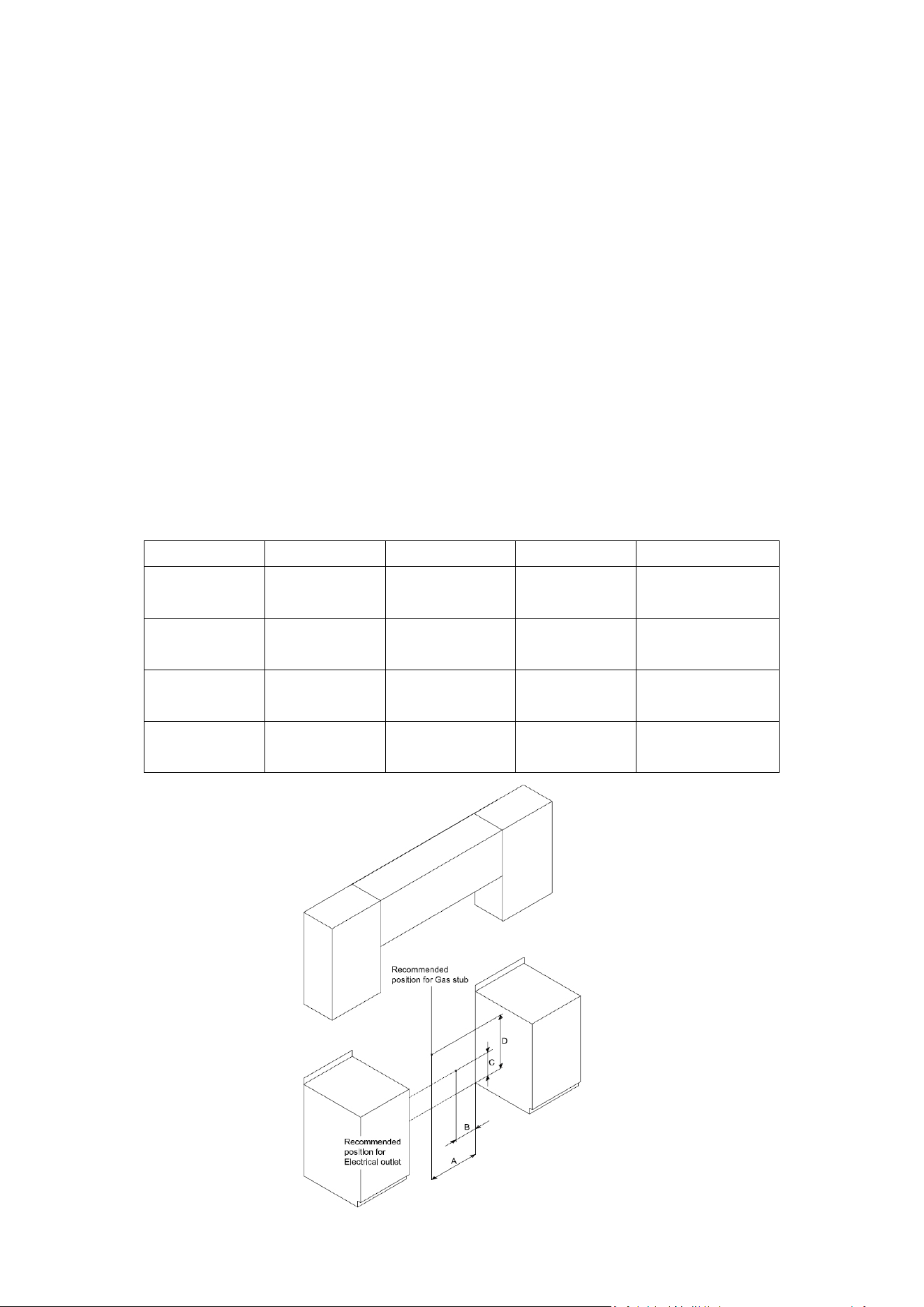
GAS AND ELECTRICAL SERVICE
• The shaded area shown below denotes the location of the gas inlet and the electrical
junction box/receptacle. This is the recommended location. For replacement purposes,
the location of the existing utilities may be utilized provided they do not interfere with
the sides or rear of the range. Check local building codes for permissible gas valve
locations.
• An external manual shut-off valve must be installed between the gas inlet and the
range for the purpose of turning on or shutting off gas to the appliance. The
installation must allow for the following:
Access to the gas shut-off valve when the unit is installed.
Access to the remote circuit breaker panel/fuse box, when the range is in place.
The gas supply piping and shut-off valve, and the electrical junction
box/receptacle must be located so they do not interfere with the range when it is
installed.
The junction box and gas shut off valve must be located so that the range can be
pulled out for service while the appliance remains connected.
Model
A
B
C
D
30”
8 7/8”
(22.5 cm)
6 5/8”
(16.8 cm)
11 3/16”
(28.4 cm)
24 ¼”
(61.6 cm)
36”
8 7/8”
(22.5 cm)
6 5/8”
(16.8 cm)
11 3/16”
(28.4 cm)
24 ¼”
(61.6 cm)
48”
15 ½”
(39,37 cm)
6 5/8”
(16.8 cm)
8 1/8”
(20.6 cm)
26 5/8”
(67.6 cm)
60”
31”
(78.7 cm)
10”
(25.4 cm)

27
PROVIDE ADEQUATE GAS SUPPLY
Be certain that the appliance being installed is correct for the gas service provided (natural
gas).
The pressure regulator located at the inlet of the cooktop manifold must remain in the supply
line regardless of whether natural or Propane gas is being used.
NOTE:
• The range top has its own regulator. Use only the provided regulator, which must be
installed in the gas line that runs from the cooktop gas inlet to the gas shut-off valve.
• For a new product, never install used connectors, which can leak gas and cause
personal injury. Use only new, flexible connectors.
ELECTRICAL REQUIREMENTS
• It is the owner’s responsibility to make sure that the electrical service meets electrical
requirements and that the electrical outlet has been properly installed by a licensed
electrician.
• Do not use an extension cord or adapter plug with this range.
• This range must be properly grounded.
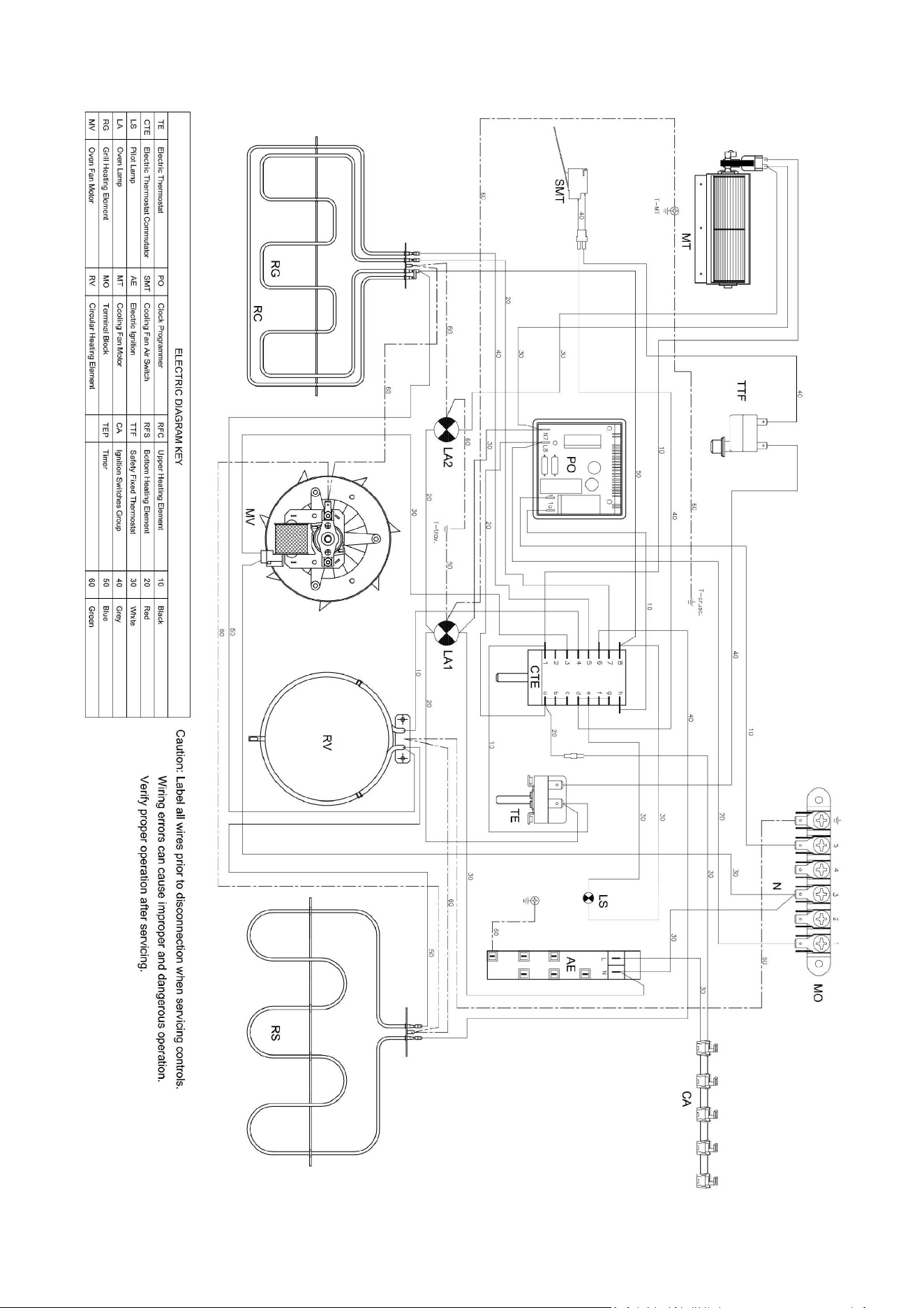
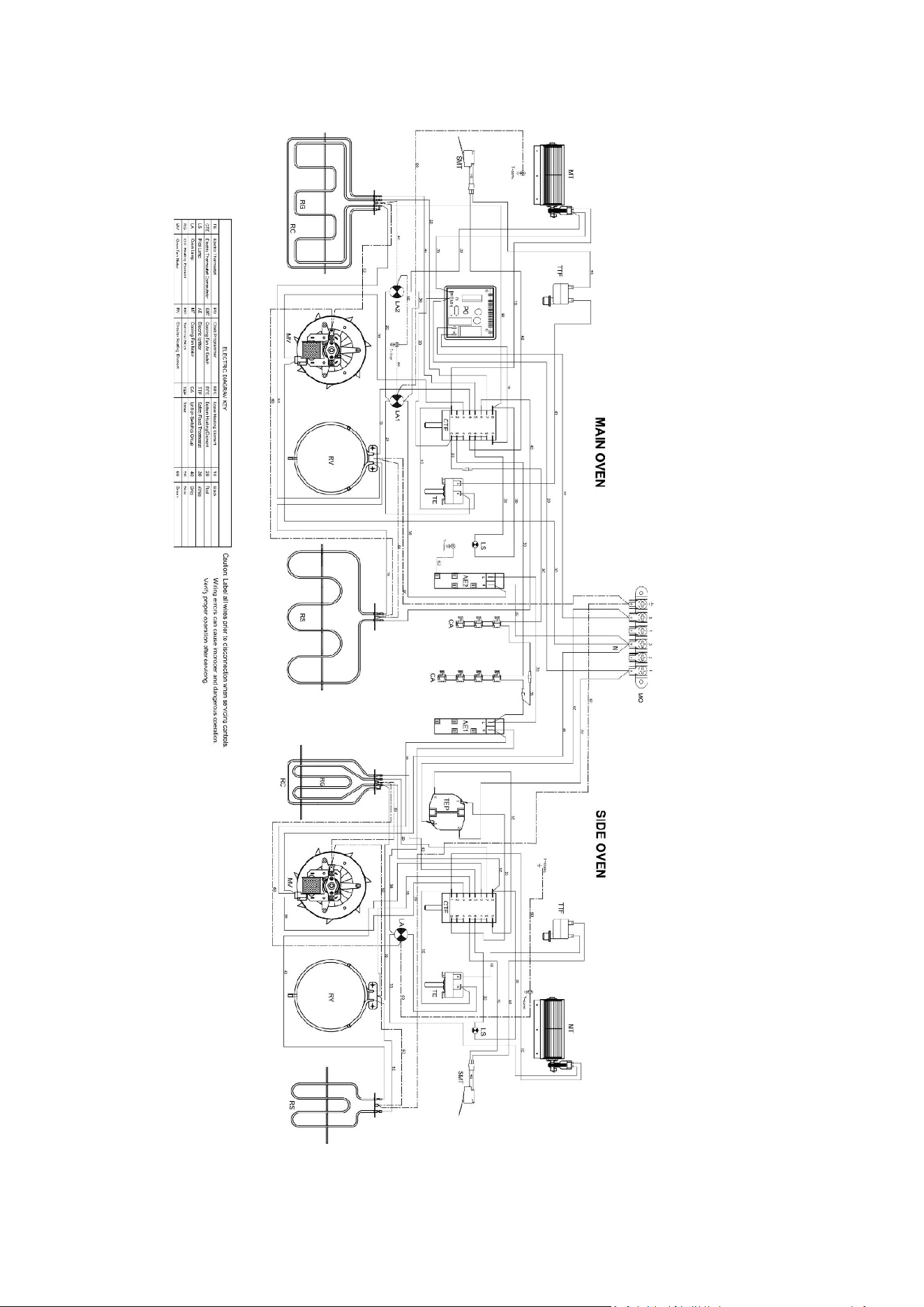
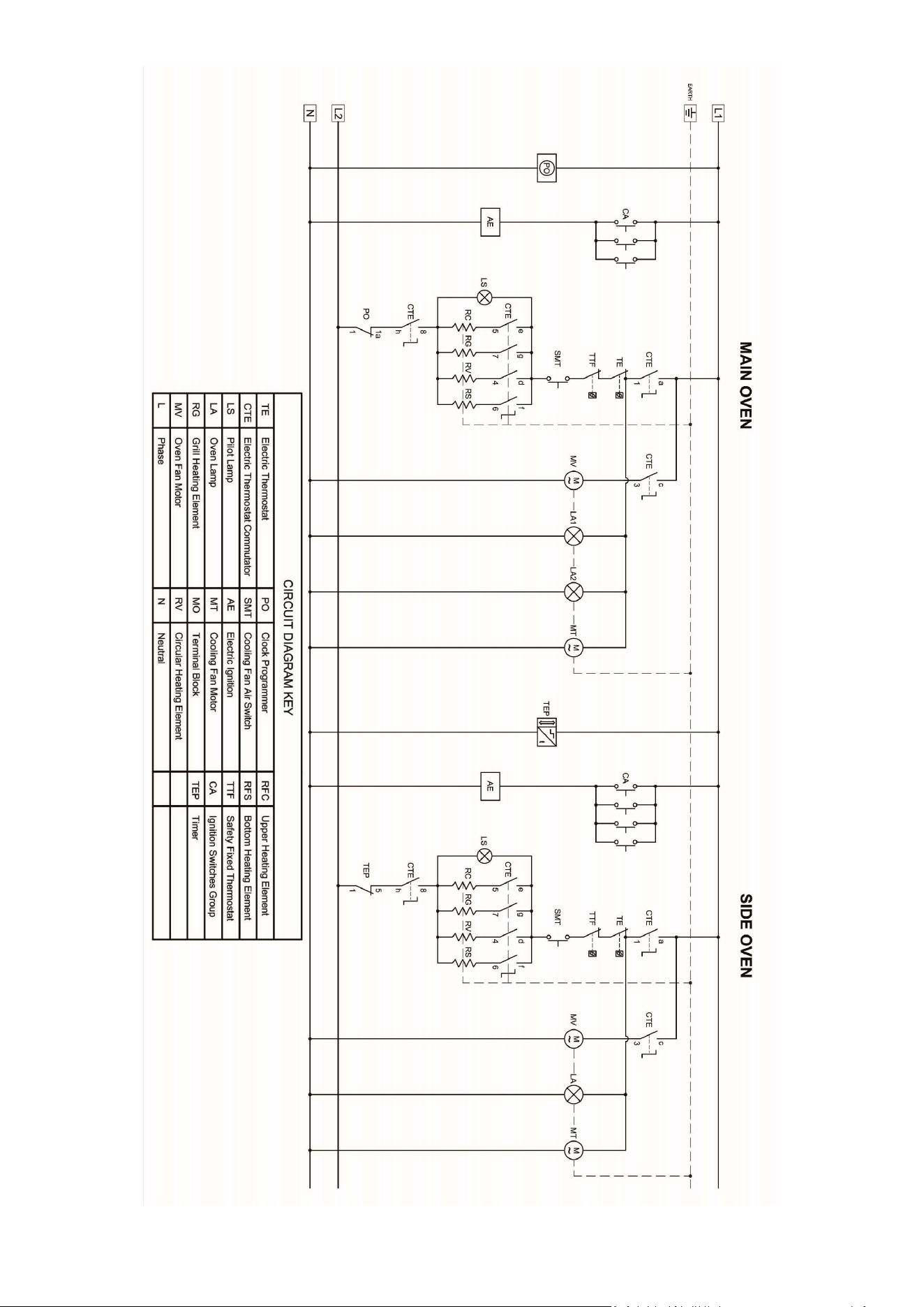
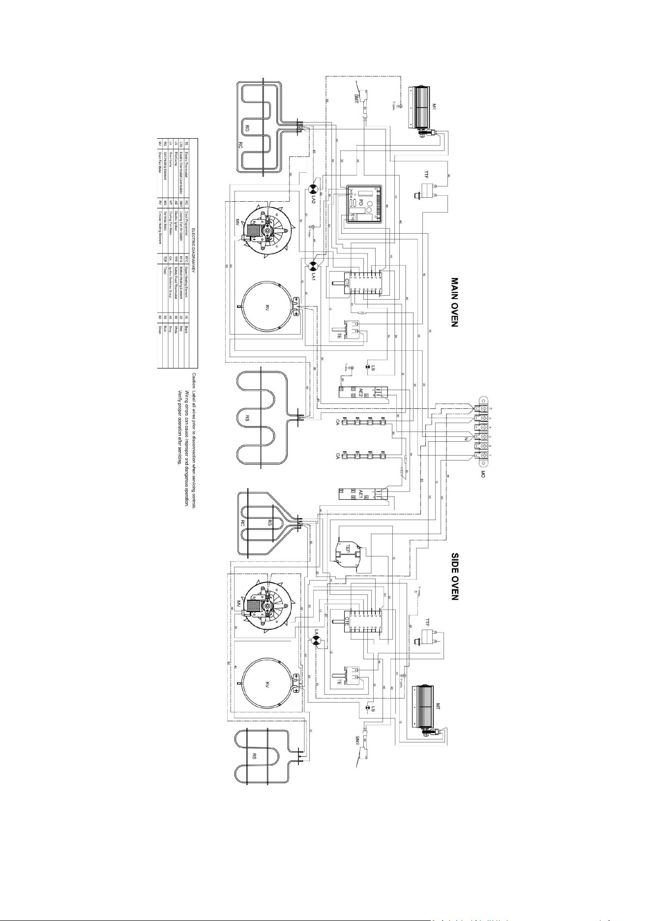
• Wiring diagram is located on the back of the range. (Inside of the cover back wire)
• A dedicated circuit breaker is recommended.
28
30” - 36” COOKER
29
30
48” COOKER
31
32
60” COOKER
33
34
INSTALLATION INSTRUCTION
The maximum depth of cabinets installed above top surface cooking sections must be 13
in (330 mm).
The installation shall be made with a connector that complies with the Standard for
Connectors for Movable Gas Appliances, ANSI Z21.69 – CSA 6.16, and a quick-disconnect
device that compiles with the Standard for Quick – Disconnect Devices for Use With Gas
Fuel, ANSI Z21.41 – CSA 6.9.
The manual valve must be installed in an accessible location in the gas piping.
PREPARING FOR INSTALLING:
1. Unpacking the Range
Unpack the parts box and verify that all required components have been provided.
If any item is missing or damaged, please contact your dealer immediately. Do not install a
damaged or incomplete appliance.
2. Removing the Oven Door
• Do not attempt to disengage the hinge catches with the door(s) removed from the
range. The hinge springs could release causing personal injury.
• Do not lift or carry the oven door(s) by the handle.
• To make the range easier to move, remove the door(s) to reduce weight.
3. Electrical connection
For personal safety, do not use an extension cord with this
appliance. Remove house fuse or open circuit breaker
before beginning installation.
Only a 4-conductor power-supply cord kit rated 125/250V,
50A, with ring or fork type connector and marked for use
with ranges shall be used.
14-50R standard
with ground
NEMA plug
14-50R standard
with ground
When replacing the power cord,
replace it only with a suitable UL
or CSA only with a suitable UL or
CSA listed cord (with the same
specifications as the same
specifications as the cord being
replaced).
35
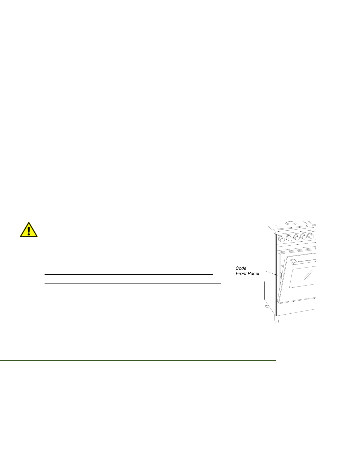
CUSTOMER SERVICE INFORMATION
The serial number, model can be found on the inner side of door trim.
For all other information about the appliance, see the labels on the back
of the appliance.
4. Gas connection
• Make sure the gas supply valve is off and that the power to the
range is turned off at the circuit breaker or fuse box prior to connecting the gas line.
• Do not apply excessive pressure when tightening gas connections and fittings.
• Do not use Teflon tape or plumber’s putty on gas flex line connections.
• Check all gas lines for leaks as instructed to avoid a fire or explosion hazard. Do not
use a flame to check for leaks.
The gas pressure regulator is pre-set at the factory for the type of gas intended for use with
the appliance. To verify that the appliance is compatible with the type of gas available, check
the range rating label.
Consult your dealer if the range is not compatible with the type of gas supplied.
Before sliding the range into the cabinet:
1. Make sure the gas supply valve is in the off position and that power to the range is off.
2. Connect a flexible gas supply line to the gas shut-off valve previously installed on the
stub out. The gas line needs to be long enough to allow the range to be pulled out for
service.
3. Connect the gas line to the regulator.
4. Turn all cooktop control valves to the “OFF” position. Turn on the gas supply.
5. Check all lines and connections for leaks using a soap and water solution.
6. After verifying that there are no gas leaks, turn off the gas supply valve connected to
the range to the “OFF” position.
5. Final installation
• Peel the protective coating off the range, including the door.
• Measure from the floor to the countertop. Adjust the levelling legs as required to
position the trim around the cooktop even with or above the countertop.
6. Installing the knobs for surface burners
When installing the knobs, align the “D” shaped opening on the back of the knob with the end
of the valve shaft. Carefully push the knob on until it stops.
There are two (2) different types of knobs supplied with the range.
36
7. Assembling the range top burners
• Do not operate the range top burners without all burner parts in place.
• Do not push in any range top controls while removing the burner; a slight electrical
shock might result, perhaps causing you to knock over hot cookware.
• Do not risk electric shock by removing the top or touching the electrode of any burner
while another burner is on.
8. Installing the grates
For best results and longest life, install the grates as instructed below. When installed
properly, the openings in the grates are centred over the burners.
The grates occupy specific positions on the range top. For maximum stability and safe
operation, these grates should only be used in their proper positions.
Grates are not interchangeable.
INJECTORS TABLE – MAXIMUM INLET PRESSURE TO THE REGULATOR
BURNERS
NOMINAL POWER
BTU/hr
NATURAL GAS (A)
Manifold Pressure (i.w.c.)
5" (12.7cm) (12.5mbar)
PROPANE (E)
Manifold Pressure (i.w.c.)
10" (25.4cm) (25mbar)
min line pressure (i.w.c.)
min pression de ligne (i.w.c.)
6" (15.2cm) (15mbar)
min line pressure (i.w.c.)
min pression de ligne (i.w.c.)
11" (27.9cm) (27.4mbar)
max line pressure (i.w.c.)
max pression de ligne (i.w.c.)
14" (35.6cm) ) (34.9mbar)
max line pressure (i.w.c.)
max pression de ligne (i.w.c.)
14" (35.6cm) (34.96mbar)
Ø injector
(1/100 mm)
Ø injector
(1/100 mm)
Auxiliary
4000
90
60
Semi-rapid (SR)
7000
120
78
Rapid (R)
11000
150
96
Dual (D)
16000
80/165
50/105
REGULATING THE MINIMUM OUTPUT OF THE HOB BURNERS
Normal/valve taps
Ignite the burners and turn the knob to the maximum position. Remove the knob and insert a
small flat-head screwdriver into the holes on the side of the control panel, in accordance with
the type.
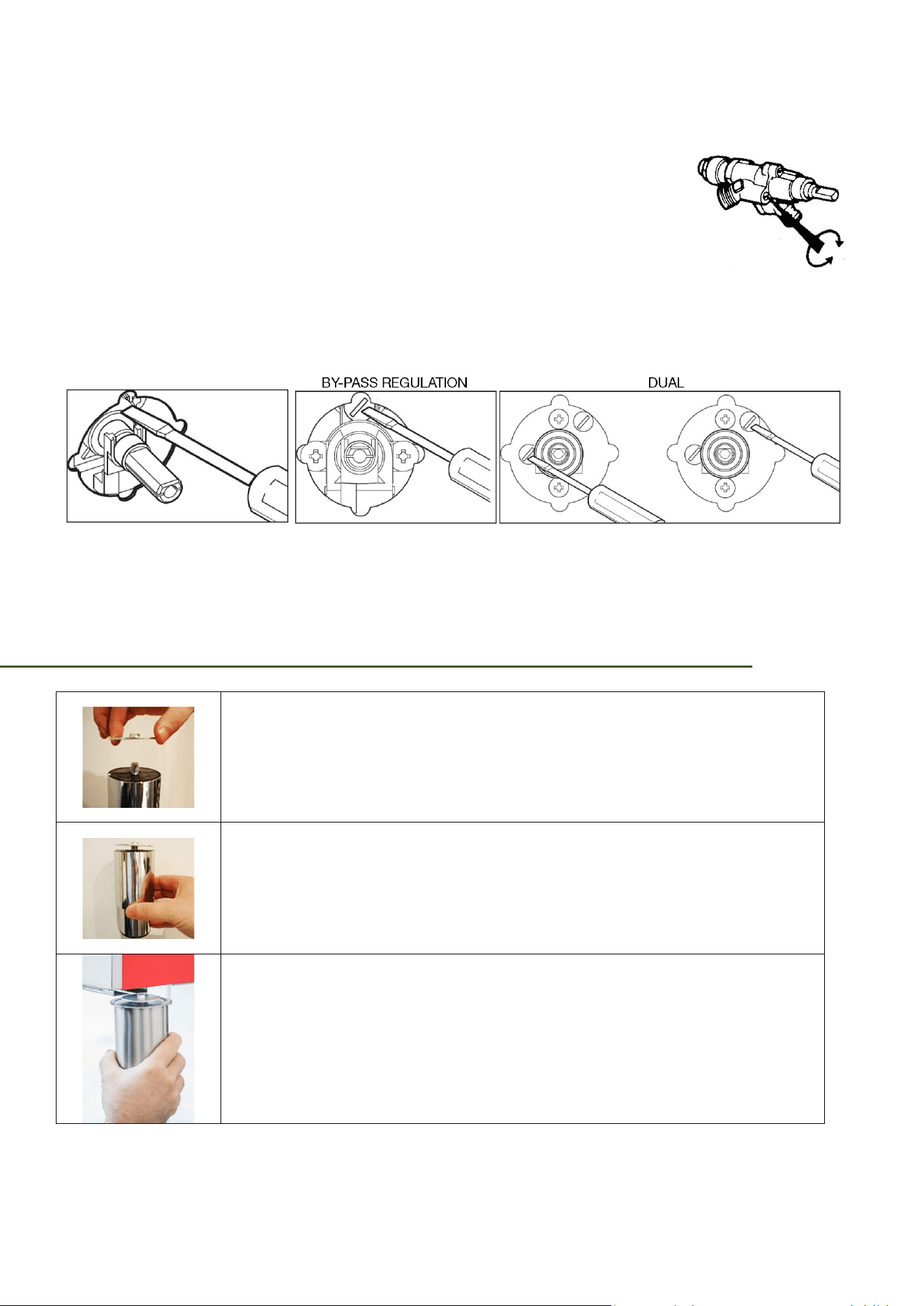
37
Loosen the by-pass screw by two turns in an anti-clockwise direction and rotate the rod to the
minimum position.
Adjust the previously loosened screws until the flame is lowered but
stable, even when rapid changes are made from the maximum to the
minimum position with the burner cold. If safety taps are fitted, let the
burner run on minimum for a few minutes to ensure that the device
does not cut in. If does, increase the minimum.
N.B.: for liquid gas settings, the burner minimum must be set by
fully tightening the tap by-passes.
N.B. Follow these instructions also after the replacement of the injectors from
methane to propane gas (see the section “Gas conversion”).
FITTING THE ADJUSTABLE METAL FEET
When fitting the washer to the leg bolt make sure, the burr on the washer
is facing upward away from the leg top.
Leg assembly with washer fitted correctly. The lower part of the leg
will unscrew to adjust the height and level of the cooker.
Insert washer fitted to top of leg into base of cooker and slide the
leg along the channel.
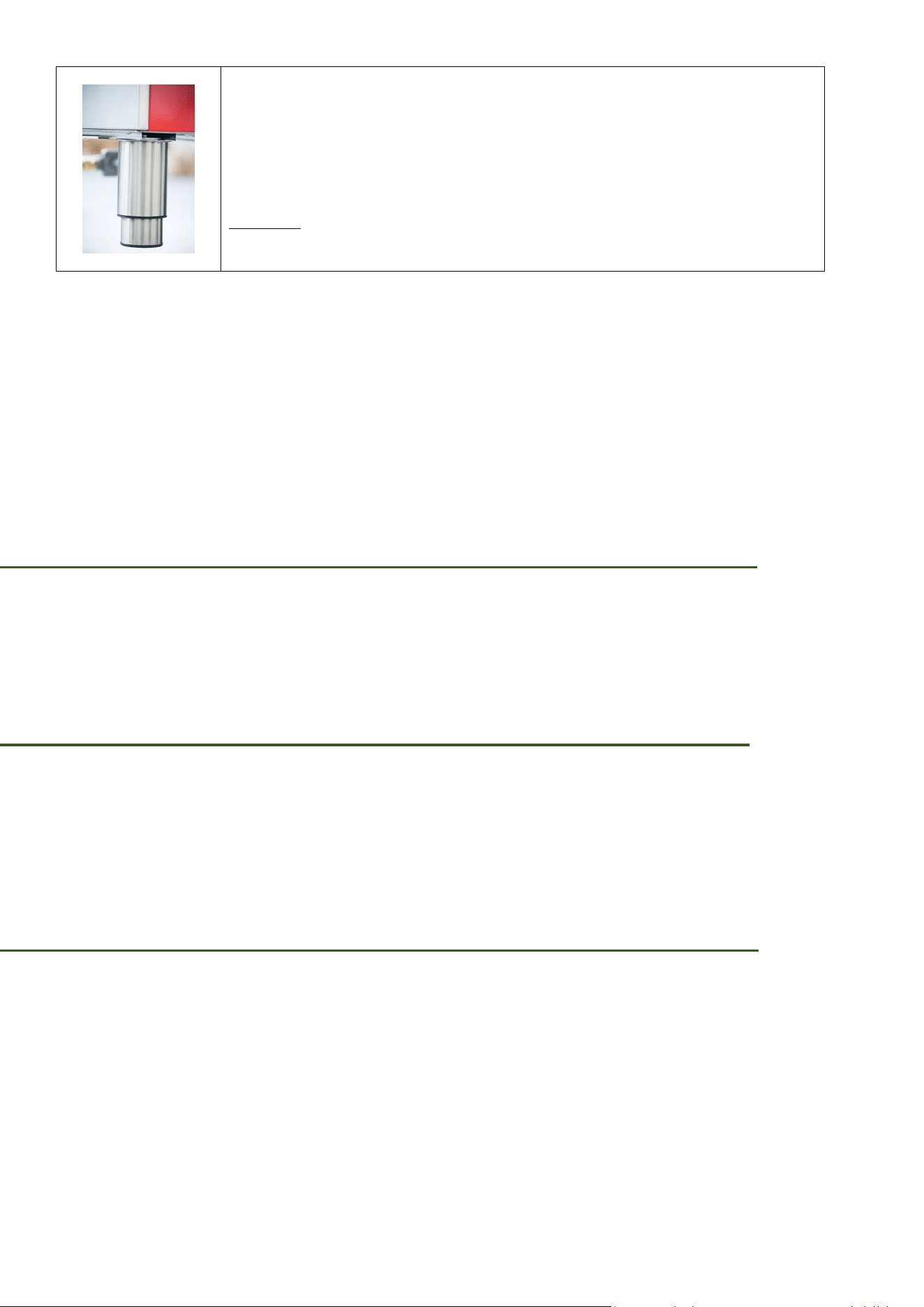
38
Screw the leg up tight so the oven base is clamped between the
washer and the top of the leg. Once all four legs have been fitted
lift cooker onto the legs taking care to distribute the weight evenly
onto all four legs at the same time.
DO NOT tip the appliance onto its legs, always lift the appliance
onto its legs. (This will require two people).
For the installation, anchor the cooker by using the supplied kit referring to the relevant
drawing. We provides two brackets, which will serve to anchor the wall-terminal of the cooker.
We must fix the brackets to the wall, following the instructions of the drawings. We must then
slightly lift the cooker to let in the bracket on the crease of the wall-terminal or working top
cooker.
IMPORTANT: The cooker with and without backsplash must be raised slightly in order to
let the bracket on the edge of the hob.
WHEN ALL HOOKUPS ARE COMPLETE
Make sure all controls are left on the OFF position.
Make sure the flow of combustion and ventilation air to the range is unobstructed.
LEVEL THE RANGE
The floor where the range is to be installed must be level. Follow the instructions under
“Levelling the Range – Models Equipped with Levelling Legs”.
Slide the range into the cut-out opening.
MODELS EQUIPPED WITH LEVELING LEGS
Level the range and set cooktop height before installation in the cut-out opening.
1. Install an oven rack in the center of the oven.
2. Place a level on the rack. Take 2 readings with the level placed diagonally in one
direction and then the other. Level the range, if necessary, by adjusting the four leg
levellers with a wrench.
39
3. Taking care to not damage the countertop, slide range into cut-out opening and double
check for levelness.
MODEL AND SERIAL NUMBER LOCATION
The serial plate is located on the oven front frame behind the oven door or on the drawer
side frame.
When ordering parts for or making inquiries about your range, always be sure to include the
model and serial numbers and a lot number or letter from the serial plate on your range.
Your serial plate also tells you the rating of the burners, the type of fuel and the pressure the
range was adjusted for when it left the factory.
BEFORE YOU CALL FOR SERVICE
Read the Avoid Service Checklist and operating instructions in your Use and Care Guide. It
may save you time and expense. The list includes common occurrences that are not the
result of defective workmanship or materials in this appliance.
Refer to the warranty and service information in User Manual for phone number and
address.
Please call or write if you have inquiries about your range product and/or need to order
parts.
REMOVAL AND RE-INSTALLATION
Removing the Range for Service
1. Turn the gas supply valve to the off position.
2. Turn off power to the range at the circuit breaker panel or fuse box.
3. Pull the range out from the wall.
WARNING:
To prevent flare-ups and avoid creation of harmful by-products, do
not use the cooktop without all burner caps properly installed to
insure proper ignition and gas flame size.
Always keep the burner caps and burner heads in place whenever
the surface burners are on use. Do not allow spills, food, cleaning
agents or any other material to enter the gas orifice holder
openings.
40
Reinstalling the Range After Service
1. Push the range into operating position, making sure the anti tip bracket is engaged
(see page 37 and following).
2. Turn on power to the range at the circuit breaker panel or fuse box.
3. Turn the gas supply valve to the on position.
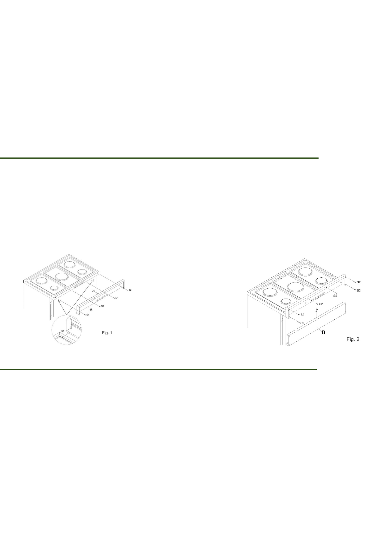
ASEMBLING THE BACKGUARD
Backguard assembly instructions:
1. Remove the protective film from the backguard.
2. Place the backguard on the hob in correspondence with the references and fix the
screws S1 and S2 as in fig.1.
3. Insert from below part B and fix the screws S2 as in fig.2.
The screws are included in the backguard kit.
INSTALLATION OF THE ANTI-TILTING DEVICE
FOR 30” – 36” RANGE COOKER
Adjustable bracket
1. Insert the bolt through the bracket, adjust the length of the bolt as needed and fix it in
place by using the two provided nuts.
2. Make sure the nuts are well tightened.
3. Fix the bracket on the back of the cooker in the appropriate holes by using the four
supplied screws.
4. Anchor bracket
5. The dotted line indicates the position of the installed cooker.
41
ANCHOR BRACKET FASTENING
The bracket can be fixed in two ways: on the floor or on the back wall.
Four wood screws and four screws with plastic plugs are provided.
Use the appropriate screws, according to the type of material in the wall or floor.
If using plastic plugs: make holes 0 8 and insert the plugs before fixing the bracket with the
screws.
Slide the cooker into place, making sure the bolt fits into the slot of the anchor bracket.
IMPORTANT:
Before drilling holes or inserting screws into the floor or
wall make sure not to damage electrical wiring or piping.
42
FOR 48” – 60” RANGE COOKER
Adjustable bracket
1. Insert the bolt through the bracket, adjust the length of the bolt as needed and fix it in
place by using the two provided nuts.
2. Make sure the nuts are well tightened.
3. Fix the bracket on the back of the cooker in the appropriate holes by using the four
supplied screws.
4. Anchor bracket
5. The dotted line indicates the position of the installed cooker.
ANCHOR BRACKET FASTENING
The bracket can be fixed in two ways: on the floor or on the back wall.
Four wood screws and four screws with plastic plugs are provided.
Use the appropriate screws, according to the type of material in the wall or floor.
If using plastic plugs: make holes 0 8 and insert the plugs before fixing the bracket with the
screws.
Slide the cooker into place, making sure the bolt fits into the slot of the anchor bracket.
43
ANTI TIP DEVICE
To check the installation of the anti-tipping safety system,
we recommend that you view the installation of the bracket
under the kitchen (in the visible part between the feet, see
illustration).
IMPORTANT:
Before drilling holes or inserting screws into the floor or
wall make sure not to damage electrical wiring or piping.
WARNING:
A child or adult can tip the range and be killed.
Verify the anti-tip device has been properly installed and
engaged to the structure.
Ensure the anti-tip device is re-engaged when the range is
moved.
Do not operate the range without the anti-tip device in place
and engaged.
Installing the anti-tip device to the structure and/or the
appliance.
Engage the range to the anti-tip device by using the four
supplied screws.
Re-engaged the anti-tip device if the range is moved.
See installation instructions for details.
Failure to do so can result in death or serious burns to
children or adults.
44
INSTALLATION OF THE FRONT PROTECTION OF THE HOB
To increase the distance between the front edge of the hob
and the burners it is possible to install the front protection
supplied with the appliance.
For installation, see Fig. A and the supplied screws.
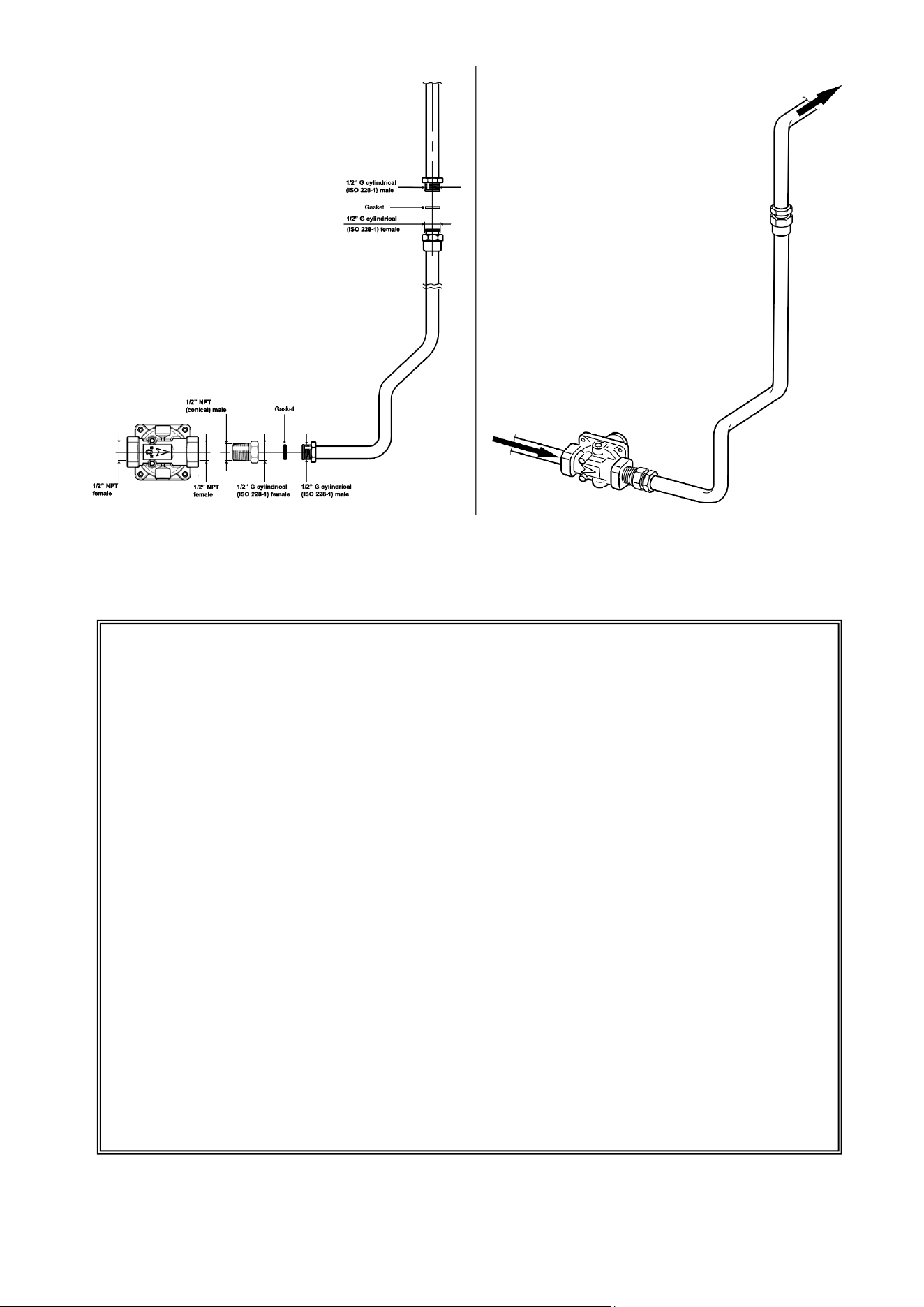
GAS CONNECTION
The supply line should be equipped with an approved shutoff valve. This valve should be
located in the same room as the range and should be in a location that allows ease of
opening and closing.
Do not block access to the shutoff valve. The valve is for turning on or shutting off gas to the
appliance.
Open the gas shutoff valve in the gas supply line. Wait a few minutes for gas to move through
the gas line.
The gas supply between the shutoff valve and the regulator may be connected by
A.G.A./C.G.A.-approved flexible metallic union- connected piping where local codes permit
use.
WARNING:
Explosion Hazard
• Use a new CSA or UL approved gas supply line.
• Install a shut-off valve.
• Securely tighten all gas connections.
• If connected to Propane, have a qualified person make
sure gas pressure does not exceed 14” water column.
• Examples of a qualified person include licensed heating
per- sonnel, authorized gas company personnel, and
authorized service personnel.
•
Failure to do so can result in death, explosion, or fire.
45
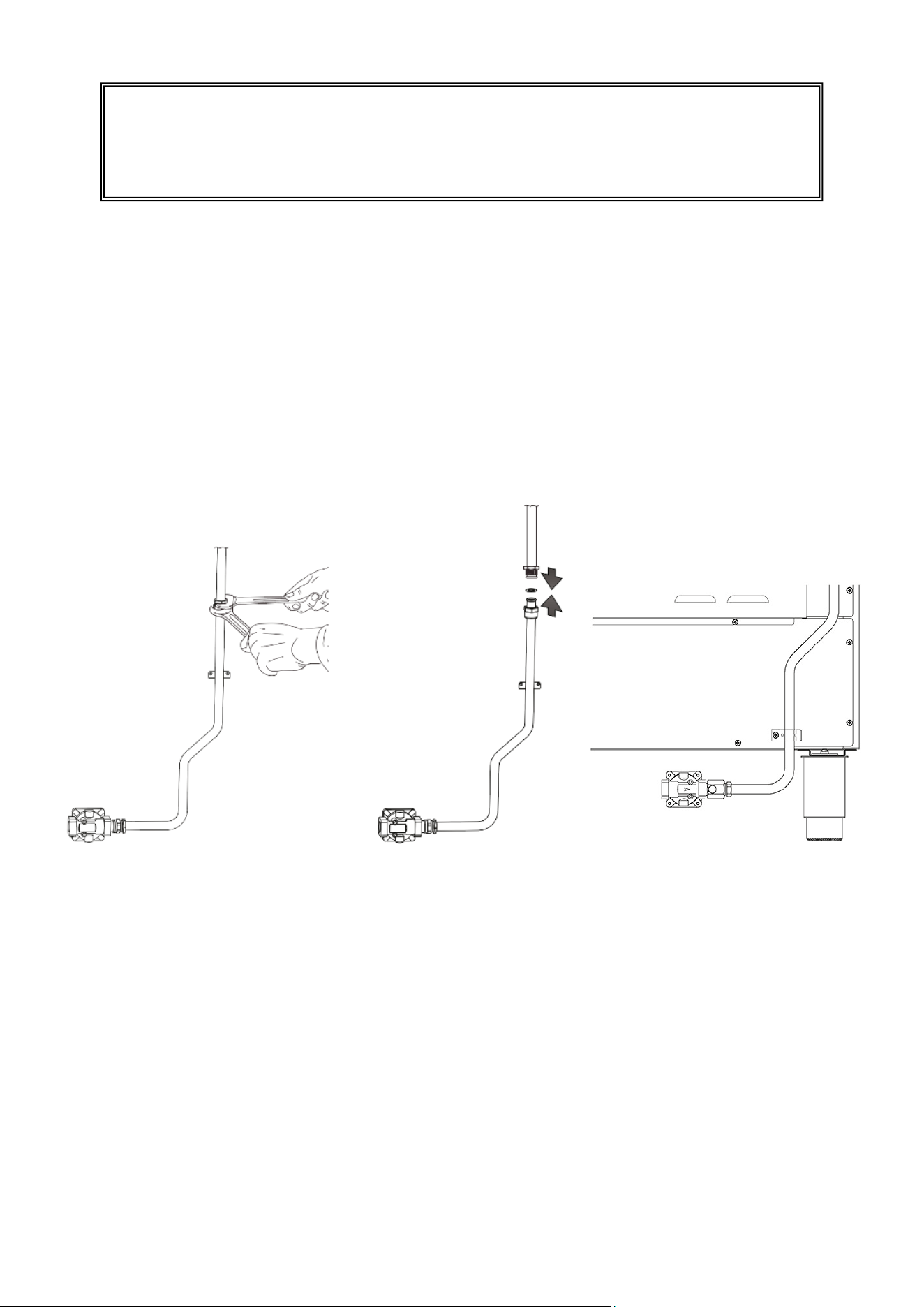
Connect the extension pipe and pressure regulator group to the range gas manifold ensuring
the supplied gasket is positioned between. The regulator cover must be oriented toward the
front side of the range.
IMPORTANT:
Use two wrenches to tighten the connection.
Fix the extension pipe support bracket onto the back of the range using the two supplied
screws.
Take care to ensure the bracket is fitted the right way up with the opening at the top.
The regulator cover must be oriented toward the front side of the range.
Gas connection specification:
WARNING:
You must use stability anti tip bracket to prevent unit from
tipping.
46
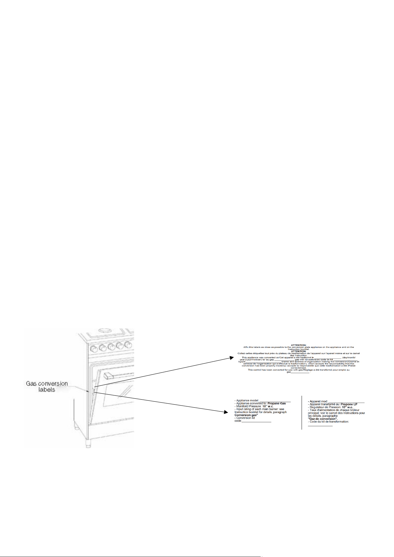
GAS CONVERSION
WARNING:
This conversion kit shall be installed by a qualified service
agency in accordance with the manufacturer’s instructions
and all applicable codes and requirements of the authority
having jurisdiction. If the information in these instructions is
not followed exactly, a fire, explosion or production of
carbon monoxide may result causing property damage,
personal injury or loss of life. The qualified service agency is
responsible for the proper installation of this kit. The
installation is not proper and complete until the operation of
the converted appliance is checked as specified in the
manufacturer’s instructions supplied with the kit.
Check that there is an identification list of all the
components provided by gas conversion nozzle kits inside
the appliance.
Save the orifices removed from the appliance for future use.
47
The kitchen is factory tested with Natural Gas, it can be converted into propane using the
nozzle kit supplied with the product, following the appropriate instructions.
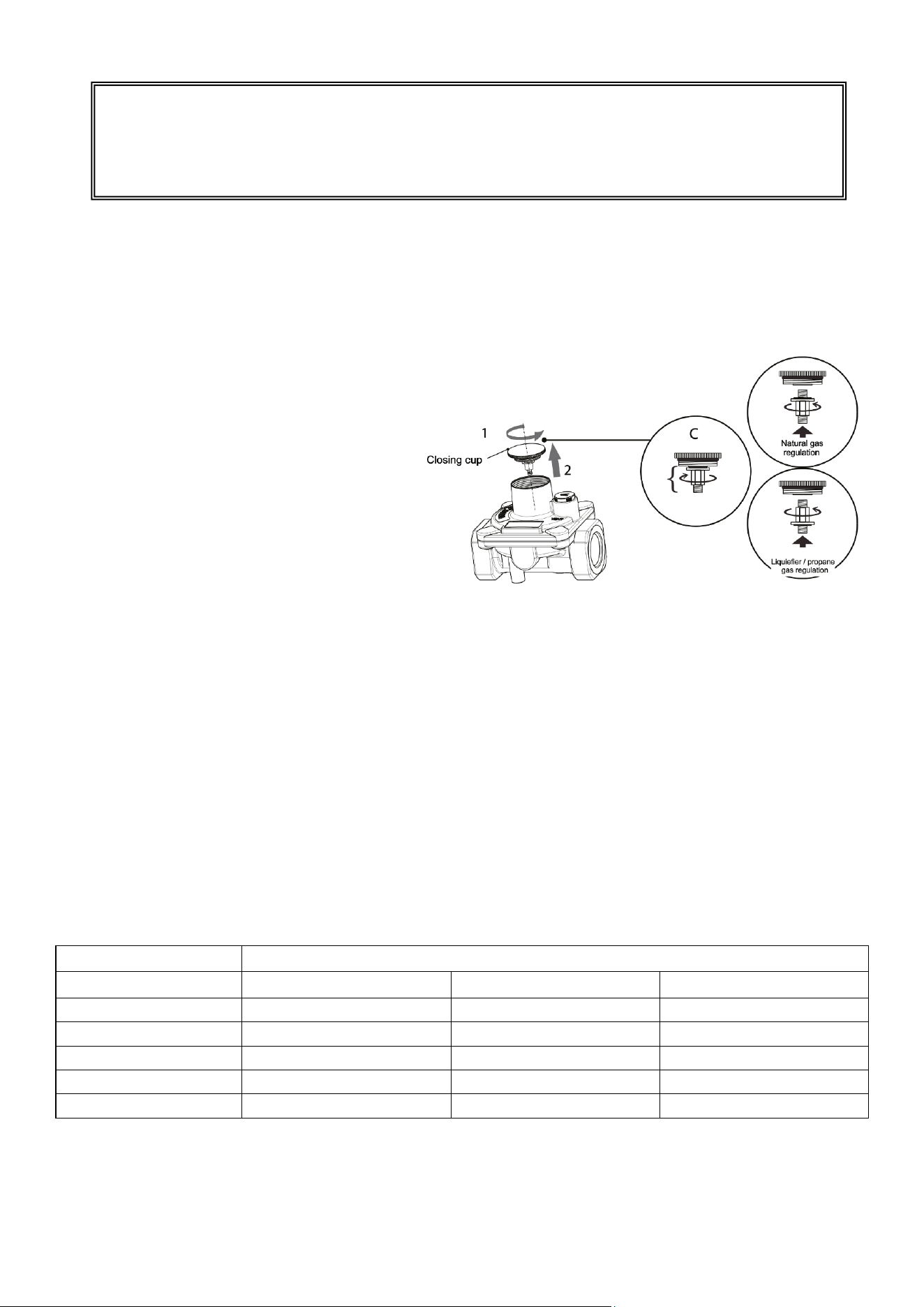
IMPORTANT:
Check the correct positioning of the gas
regulator. The arrow on the back of the
gas regulator must be oriented toward
the connector.
To adjust the pressure regulator:
1. Unscrew the regulator cover
2. Unscrew the component “C”,
invert and screw it in the direction
of the regulation.
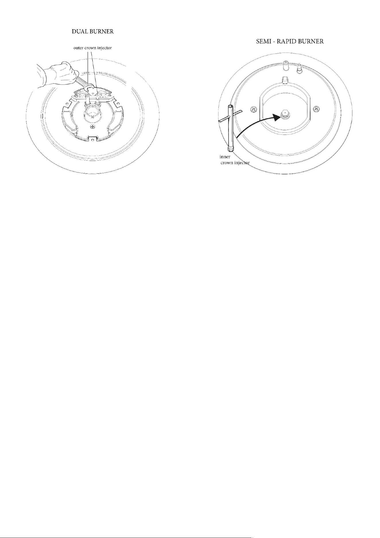
OPERATIONS TO BE PERFORMED WHEN SUBSTITUTING THE INJECTORS
Remove the gratings and the burner covers
Remove currently installed injectors with a wrench
Using a wrench substitute the nozzle injector with those most suitable for the kind of
gas for which it is to be used.
The burner are conceived in such a way so as not to require the regulation of the primary air.
Components list table (Propane Gas Injector)
Appliance dimensions
Burner
30” - 36”
48”
60”
Auxiliary
1 injector Ø 0.60 mm
1 injector Ø 0.60 mm
1 injector Ø 0.60 mm
Semi-rapid
1 injector Ø 0.78 mm
3 injector Ø 0.78 mm
3 injector Ø 0.78 mm
Rapid
2 injector Ø 0.96 mm
2 injector Ø 0.96 mm
2 injector Ø 0.96 mm
Dual (internal crow)
1 injector Ø 0.50 mm
1 injector Ø 0.50 mm
2 injector Ø 0.50 mm
Dual (external crow)
1 injector Ø 1.05 mm
1 injector Ø 1.05 mm
2 injector Ø 1.05 mm
WARNING:
The gas supply shall be shut off prior to disconnecting the
electrical power, before proceeding with the conversion
48
N.B. Repeat the minimum adjustment operation (see the section “Regulating the
minimum output of the hob burners”)
N.B. Check that by pressing and turning the knob the burner is correctly lit with a
stable flame.
TEST THE APPLIANCE
If you are interested in checking the possible leakage of your appliance; please proceed in the
following way:
1. Please take a brush and a liquid detergent in order to check all the gas connections. If
you see any bubble around the connections, there is a leakage.
2. If you see a leakage, please switch off the gas valve controls and please proceed to fix
the connections.
3. Please check again the connections
4. Please proceed to remove all the remaining detergent from the appliance
5. Please replace the components on the burner and turn the knobs on the gas tap
valves.
ATTENTION: PLEASE DO NOT TEST FOR GAS LEAKAGES USING MATCHES OR OTHER
FLAMES.
6. Please check the presence of blue color of the flame at the maximum flame position.
The flame should be clean and soft in character and you should not see any blowing or
lifting of the flame. Please be so kind to note that you may see some orange flashes
that are normal.
7. Please wipe away all the remaining detergent from the appliance.
AUXILIARY RAPID
49
8. Please replace the components on the burner and turn the knobs on the gas tap valve.
Minimum adjustment:
• FOR NATURAL GAS:
Please light the burner and turn the know at the minimum position
Please then remove the gas tap knob and turn the adjustment screw at the sides of the tap
rod until you reach the minimum required flame.
Please refit the knob and check whether the flame is stable (the flame should not go out
while turning the knob quickly from the maximum to the minimum position).
Please proceed to repeat this operation on the other remaining gas taps of the hob.
• FOR PROPANE GAS:
Please switch off the burner and proceed to disconnect the cooker from the electrical power
supply.
In order to regulate the minimum with Propane gas, please verify that the screws at the sides
of the tap rods must be turned clockwise.
Once you have completed the regulation, please replace the seal on the by-passes using
some paint or similar materials.
Please read the instructions of point 9 to identify the adjustment screws.
Warning: once the test has been completed, apply the conversion label present in the
kit inside the kitchen door next to the serial number label.
SEAL THE OPENINGS
Seal any openings in the wall behind the range and in the floor under the range after gas
supply line is installed.
50
CONNECT THE RANGE TO THE GAS SUPPLY
Important: remove all packing material and literature from range before connecting gas and
electrical supply.
To prevent leaks, put pipe joint sealant on all external pipe threads.
CAUTION:
Do not allow regulator to rotate on pipe when tightening fittings.
CONNECTION TO PRESSURE REGULATOR
The regulator is already installed on the appliance.
CAUTION:
Do not make the connection too tight. The regulator is die cast. Overtightening may
crack the regulator resulting in a gas leak and possible fire or explosion.
The user must know the location of the main shutoff valve and have easy access to it.
When using flexible gas conduit on the range, allow sufficient slack to pull the range outside
the cut-out for the cleaning or servicing.
NOTE:
Do not allow the flexible conduit to get pinched between the wall and the range. To visually
check, remove the range drawer.
It flexible connectors are used, be certain connectors are not kinked.
GAS BURNERS
Electronic ignition integrated in the knob: turn the knob to the maximum position and press it
fully and the burner ignites automatically.
No gas supply (tap closed)
Maximum gas supply Minimum gas supply
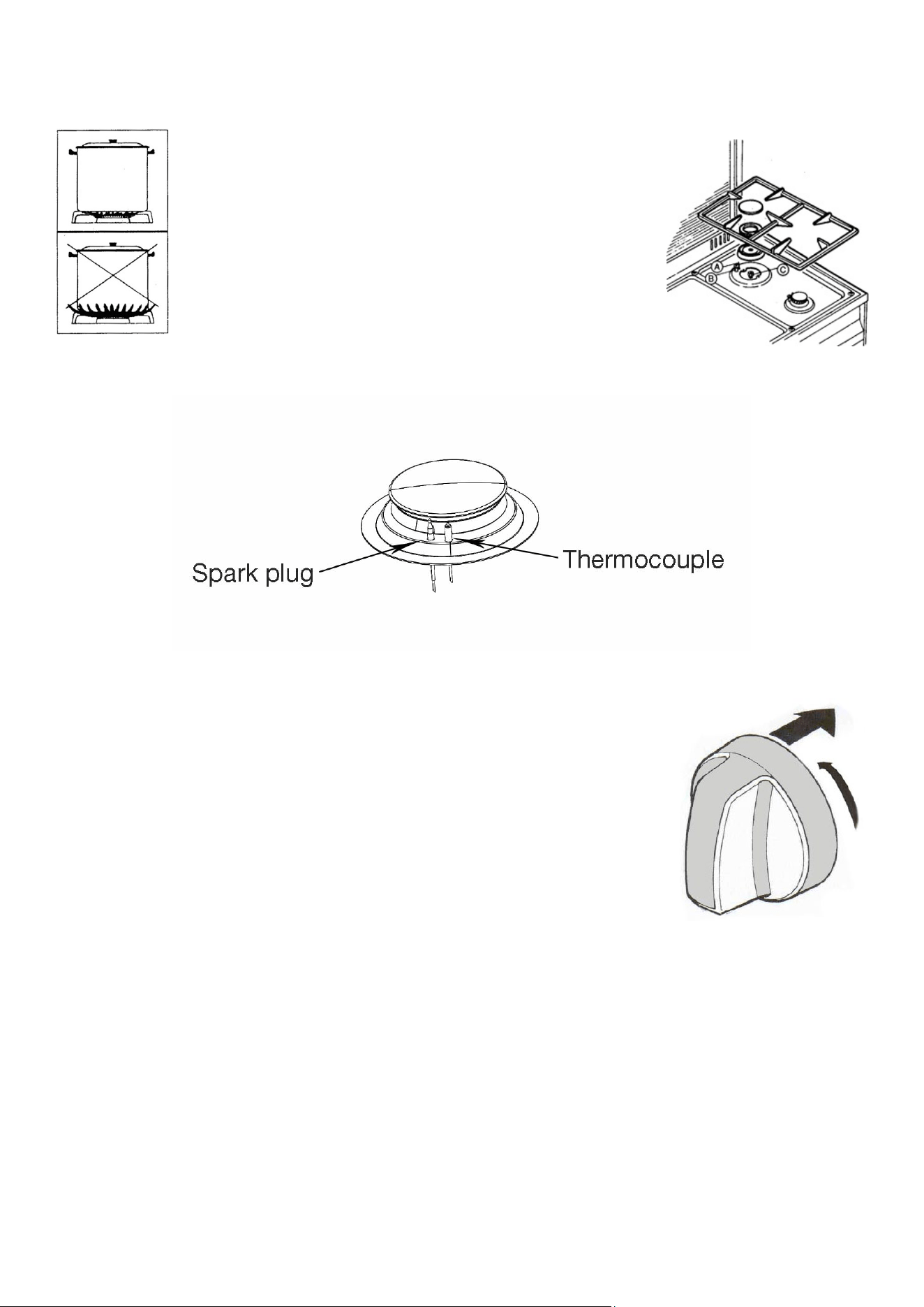
51
To obtain the minimum flow rate, turn the knob counterclockwise and position the index
finger of the knob at the small flame.
Safety device: once the burner is ignited, keep the
knob pressed for at least 5 ÷ 10 seconds and then
release, the burner remains ignited by the
thermocouple (A), which keeps the gas passage open
through a safety valve, which in case of accidental
burner shutdown interrupts the gas passage.
In the event of a momentary power failure, the hob
burner can be ignited manually using an igniter.
Push and turn the knob to the maximum gas position to induce a
flame into the desired burner.
In the event of accidental extinction of the flame, it is advisable to turn
the knob to the off position.
DISASSEMBLED AND REASSEMBLED GAS BURNERS
The burners can be disassembled and reassembled following the sequence in the picture for
cleaning and maintenance.
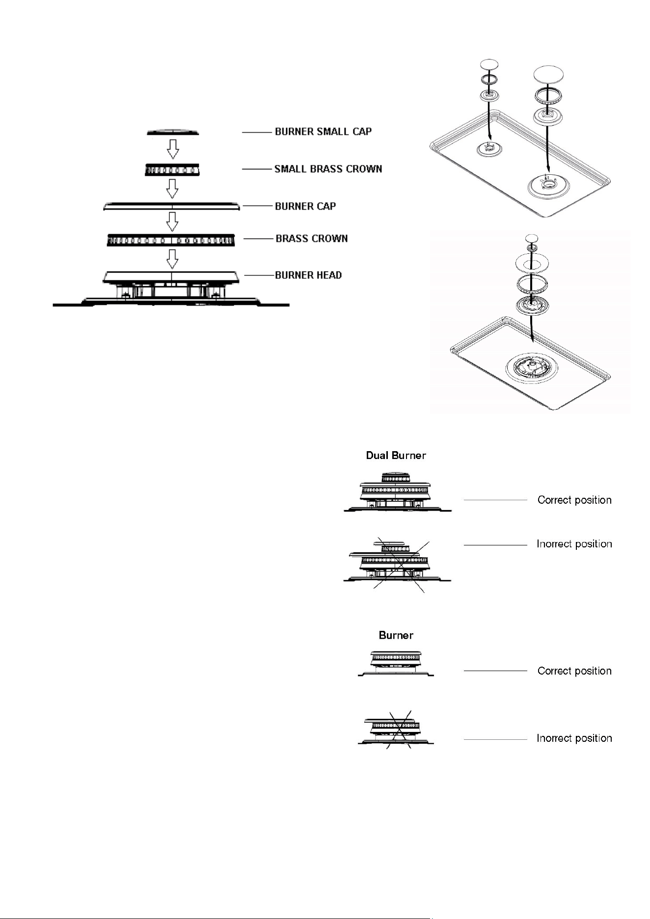
52
Assembly of the burner caps and burner
grates
It is very important to make sure that all of the
surface burner caps and surface burner grates
are installed correctly and at the correct
locations.
Once in place, you may check the fit by gently
sliding the burner cap from side to side to be
sure it is centered and firmly seated. When the
burner cap lip makes contact inside the center
of the burner head you will be able to hear the
burner cap click.
53
TEPPANYAKI
The "Teppanyaki" accessory (if available) must be placed over
two burners on the hob as shown in the photo.
WARNING: it must not be placed on the hob with only one
burner.
REMOVING AND FITTING THE OVEN DOOR
Insert an anti-rotation hinge in the appropriate holes. Hold the door by
the sides and slowly close it until you can feel a certain resistance; now,
while forcing the door closed, lift it in order to slide it out by freeing the
hinge lock from the kitchen. To refit the door repeat the above
instructions in reverse making sure the hinge lock is correctly fitted.
REPLACING THE OVEN LIGHT BULBS
To replace the oven light bulb, unscrew the protection cap that projects
out inside the oven.
NOTE: touching the bulb with fingers may cause the bulb to burn out.
Always use protective glove or use a cloth to remove the bulb.
WARNING:
Disconnect power before servicing unit.
54
MOVING THE APPLIANCE FOR SERVICING AND CLEANING
WARNING:
Before cleaning the appliance, remove broiler trays and other utensils and
wiping off all excessive spillage before initiating the cleaning cycle.
Do not clean door gasket: the door gasket is essential for a good seal. Care
should be taken not to rub, damage, or move the gasket.
Do not use oven cleaners: no commercial oven cleaner or oven liner
protective coating of any kind should be used in or around any part of the
oven.
Clean only parts listed in manual.
Before self-cleaning the oven: remove broiler pan and other utensils.
Turn off the range line fuse or circuit breakers at the main power source, and turn off the
manual gas shut-off valve.
Make sure the range is cold. Remove the service drawer (warming drawer on some models)
and open the oven door.
Lift the range at the front and slide it out of the cut-out opening without creating undue strain
on the flexible gas conduit. Make sure not to pinch the flexible gas conduit at the back of the
range when replacing the unit into the cut-out opening. Replace the drawer, close the door
and switch on the electrical power and gas to the range.
WARNING:
When raising cooker to upright position always ensure two
people carry out this manoeuvre to prevent damage to the
adjustable feet.
Be careful: do not lift the cooker by the door handle when
raising to the upright position.
When moving cooker to its final position, DO NOT DRAG. Lift
feet clear of floor.
55
RANGE INSTALLATION
IMPORTANT NOTE:
Door removal is not a requirement for installation of the range, but is an added convenience.
For models equipped with LEVELING LEG only (no levelling device):
Make sure the four levelling legs (front and rear) are setup higher than the height of the
cabinet.
CAUTION:
Install the anti-tip bracket at this point before placing the range at its final position.
Follow the installation instruction on the anti-tip bracket template supplied with the
range.
CAUTION:
To reduce the risk of damaging your appliance, do not handle or manipulate it by the
cooktop. Manipulate with care.
Position range in front of the cabinet opening.

Nuova Lofra S.r.l.
Via Montegrotto, 125 – 35038 TORREGLIA (PADOVA) – ITALY
Tel.: +39 049 9904811
Telefax: +39 049 9904800
Website: www.lofra.us
03202775 Rev 1.25 – 10/10/2022