Owner’s Manual &
Installation Manual
IMPORTANT NOTE:
Read this manual carefully before installing
or operating your new air conditioning
unit. Make sure to save this manual for
future reference.
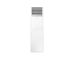
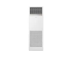
FLOOR-STANDING TYPE AIR CONDITIONER
CH-12MMC-230VI
CH-16MMC-230VI

Unit Specifications and Features
........................................................09
Owner’s Manual
Table of Contents
Safety Precautions
............................................................................04
Care and Maintenance
...................................................................13
Troubleshooting..............................................................................15
1. Indoor unit display............................................................................................................................................................09
2. Operating temperature...................................................................................................................................................10
3. Other features ....................................................................................................................................................................11
4. Adjusting Air Flow Direction..........................................................................................................................................12

Installation Manual
Accessories............................................................................................18
Unit Parts
...............................................................................................20
Indoor Unit Installation
.......................................................................21
1. Select installation location.....................................................................................................................................................21
2. Hang indoor unit........................................................................................................................................................................23
3. Drill wall hole for connective piping...................................................................................................................................24
4. Connect drain hose...................................................................................................................................................................25
Outdoor Unit Installation.........................................................................
.
26
1. Select installation location......................................................................................................................................................26
2. Install drain joint.........................................................................................................................................................................27
Wiring.........................................................................
...............................
33
1. Outdoor Uint Wiring.................................................................................................................................................................34
3. Power Specications................................................................................................................................................................36
3. Anchor outdoor unit.................................................................................................................................................................27
Refrigerant Piping Connection...........................................................29
A. Note on Pipe Length.................................................................................................................................................................29
B. Connection Instructions –Refrigerant Piping...................................................................................................................30
1. Cut pipe.....................................................................................................................................................................................30
2. Remove burrs..........................................................................................................................................................................30
3. Flare pipe ends.......................................................................................................................................................................31
4. Connect pipes.........................................................................................................................................................................31
Air Evacuation.....................................................................................37
1. Evacuation Instructions...........................................................................................................................................................37
2. Note on Adding Refrigerant...................................................................................................................................................38
Test Run................................................................................................39
Installation Summary...........................................................................19
2. Indoor Uint Wiring.....................................................................................................................................................................35
Safety
Precautions
Read Safety Precautions Before Operation and Installation
The seriousness of potential damage or injuries is classified as either a WARNING or CAUTION.
Incorrect installation due to ignoring instructions can cause serious damage or injury.
WARNING
This appliance can be used by children aged from 8 years and above and persons with reduced
physical, sensory or mental capabilities or lack of experience and knowledge if they have been given
supervision or instruction concerning use of the appliance in a safe way and understand the hazards
involved. Children shall not play with the appliance. Cleaning and user maintenance shall not be
made by children without supervision (EN Standard requirements).
This appliance is not intended for use by persons (including children) with reduced physical, sensory
or mental capabilities, or lack of experience and knowledge, unless they have been given supervision
or instruction concerning use of the appliance by a person responsible for their safety. Children
should be supervised to ensure that they do not play with the appliance.
WARNINGS FOR PRODUCT USE
•
If an abnormal situation arises (like a burning smell), immediately turn o the unit and disconnect
the power. Call your dealer for instructions to avoid electric shock,
re or injury
.
•
Do not
insert fingers, rods or other objects into the air inlet or outlet. This may cause injury, since
the fan may be
r
otating at high speeds.
•
Do not
use flammable sprays such as hair spray, lacquer or paint near the unit. This may cause
fi
re or combustion.
•
Do not
operate the air conditioner in places near or around combustible gases. Emitted gas may
collect a
round the unit and cause explosion.
•
Do not
•
•
Do not
expose your body directly to cool air for a prolonged period of time.
•
•
If the air conditioner is used together with burners or other heating devices, thoroughly ventilate
the
room to avoid oxygen deficiency
.
Safety Precautions
Do not
allow children to play with the air conditioner. Children must be supervised around the
unit at all times.
operate your air conditioner in a wet room such as a bathroom or laundry room. Too
much exposu
re to water can cause electrical components to short circuit.
In certain functional environments, such as kitchens, server rooms, etc., the use of specially
designed air-conditioning units is highly recommended.
Page 4
WARNING
This symbol indicates the possibility
of personnel injury or loss of life.
CAUTION
This symbol indicates the possibility of
property damage or serious consequences.
Safety
Precautions
Page 5
•
Do not
clean the air conditioner with combustible cleaning agents. Combustible cleaning agents
can cause re or deformation.
CLEANING AND MAINTENANCE WARNINGS
•
Turn o the device and disconnect the power before cleaning. Failure to do so can cause
electrical shock.
•
Do not
clean the air conditioner with excessive amounts of water.
CAUTION
•
Turn o the air conditioner and disconnect the power if you are not going to use it for a long time.
•
Turn o and unplug the unit during storms.
•
Make sure that water condensation can drain unhindered from the unit.
• Do not
operate the air conditioner with wet hands. This may cause electric shock.
• Do not
use device for any other purpose than its intended use.
• Do not
climb onto or place objects on top of the outdoor unit.
• Do not
allow the air conditioner to operate for long periods of time with doors or windows open,
or if the humidity is very high.
ELECTRICAL WARNINGS
•
Only use the specified power cord. If the power cord is damaged, it must be replaced by the
manufacturer
, its service agent or similarly qualied persons in order to avoid a hazard.
•
•
•
•
•
•
•
•
Keep power plug clean. Remove any dust or grime that accumulates on or around the plug. Dirty
plugs can cause re or electric shock.
Do not
pull power cord to unplug unit. Hold the plug firmly and pull it from the outlet. Pulling
directly on the cord can damage it, which can lead to fire or electric shock.
Do not
modify the length of the power supply cord or use an extension cord to power the unit.
Do not
share the electrical outlet with other appliances. Improper or insucient power supply
can cause re or electrical shock.
The product must be properly grounded at the time of installation, or electrical shock may occur.
For all electrical work, follow all local and national wiring standards, regulations, and the
Installation Manual. Connect cables tightly, and clamp them securely to prevent external forces
from damaging the terminal. Improper electrical connections can overheat and cause re, and may
also cause shock.
All electrical connections must be made according to the Electrical Connection
Diagram located on the panels of the indoor and outdoor units.
All wiring must be properly arranged to ensure that the control board cover can close properly. If
the control board cover is not closed properly, it can lead to corrosion and cause the connection
points on the terminal to heat up, catch re, or cause electrical shock.
If connecting power to xed wiring, an all-pole disconnection device which has at least 3mm
clearances in all poles, and have a leakage current that may exceed 10mA, the residual current
device (RCD) having a rated residual operating current not exceeding 30mA, and disconnection
must be incorporated in the xed wiring in accordance with the wiring rules.
TAKE NOTE OF FUSE SPECIFICATIONS
The air conditioner’s circuit board (PCB) is designed with a fuse to provide overcurrent protection.
The specifications of the fuse are printed on the circuit board ,such as :
T3.15A/250VAC, T5A/250VAC, T10A/250VAC, T20A/250VAC, T30A/250VAC, etc.
NOTE: For the units with R32 or R290 refrigerant , only the blast-proof ceramic fuse can be used.
Safety
Precautions
Page 6
WARNINGS FOR PRODUCT INSTALLATION
1.
Installation must be performed by an authorized dealer or specialist. Defective installation can
cause water leakage, electrical shock, or re.
2.
Installation must be performed according to the installation instructions. Improper installation
can cause water leakage, electrical shock, or re.
(In North America,installation must be performed in accordance with the requirement of NEC
and CEC by authorized personnel only.)
3.
Contact an authorized service technician for repair or maintenance of this unit. This appliance
shall be installed in accordance with national wiring regulations.
4.
Only use the included accessories, parts, and specied parts for installation. Using non-standard
parts can cause water leakage, electrical shock, re, and can cause the unit to fail.
5.
6.
Install the unit in a rm location that can support the unit’s weight. If the chosen location cannot
support the unit’s weight, or the installation is not done properly, the unit may drop and cause
serious injury and damage.
7.
8.
9.
10.
11.
Do not turn on the power until all work has been completed.
When moving or relocating the air conditioner, consult experienced service technicians for
disconnection and reinstallation of the unit.
How to install the appliance to its support, please read the information for details in "indoor unit
installation" and "outdoor unit installation" sections .
For units that have an auxiliary electric heater, do not install the unit within 1 meter (3 feet) of
any combustible materials.
Do not
install the unit in a location that may be exposed to combustible gas leaks. If
combustible
gas accumulates around the unit, it may cause re.
Install drainage piping according to the instructions in this manual. Improper drainage may
cause water damage to your home and property.
Note about Fluorinated Gasses(Not applicable to the unit using R290 Refrigerant)
1.
This air-conditioning unit contains fluorinated greenhouse gasses. For specic information on the
type of gas and the amount, please refer to the relevant label on the unit itself or
the
“Owner's Manual - Product Fiche ” in the packaging of the outdoor unit.
(European
Union products only)
.
2.
Installation, service, maintenance and repair of this unit must be performed by a certified
technician.
3.
Product uninstallation and recycling must be performed by a certified technician.
4.
For equipment that contains uorinated greenhouse gases in quantities of 5 tonnes of CO
2
equivalent or more, but of less than 50 tonnes of CO
2
equivalent, If the system has a leak-
detection system installed, it must be checked for leaks at least every 24 months.
5.
When the unit is checked for leaks, proper record-keeping of all checks is strongly recommended.
Safety
Precautions
Page 7
WARNING for Using R32/R290 Refrigerant
When ammable refrigerant are employed, appliance shall be stored in a well -ventilated area
where the room size corresponds to the room area as speciec for operation.
For R32 frigerant models:
Appliance shall be installed, operated and stored in a room with a oor area larger than
X m²
.
Appliance shall not be installed in an unvertilated space, if that space is smaller than
X m²
(Please see the following form)
.
Reusable mechanical connectors and ared joints are not allowed indoors.
(EN Standard Requirements).
Mechanical connectors used indoors shall have a rate of not more than 3g/year at 25%
of the maximum allowable pressure. When mechanical connectors are reused indoors,
sealing parts shall be renewed. When ared joints are reused indoors, the are part
shall be re-fabricated. (UL Standard Requirements)
When mechanical connectors are reused indoors, sealing parts shall be renewed. When
ared joints are reused indoors, the are part shall be re-fabricated.
(IEC Standard Requirements)
Mechanical connectors used indoors shall comply with ISO 14903.
Minimum room
area (ft)(m)
59ft/18m
Model
(Btu/h)
≤18000
Safety
Precautions
Page 8
US Disposal Guidelines
This appliance contains refrigerant and other potentially hazardous materials. When disposing of
this appliance, the law requires special collection and treatment. Do not
dispose of this product as
household waste or unsorted municipal waste.
When disposing of this appliance, you have the following options:
• Dispose of the appliance at designated municipal electronic waste collection facility.
• When buying a new appliance, the retailer will take back the old appliance free of charge.
• The manufacturer will take back the old appliance free of charge.
• Sell the appliance to certied scrap metal dealers.
Special notice
Disposing of this appliance in the forest or other natural surroundings endangers your health and is bad
for the environment. Hazardous substances may leak into the ground water and enter the food chain.
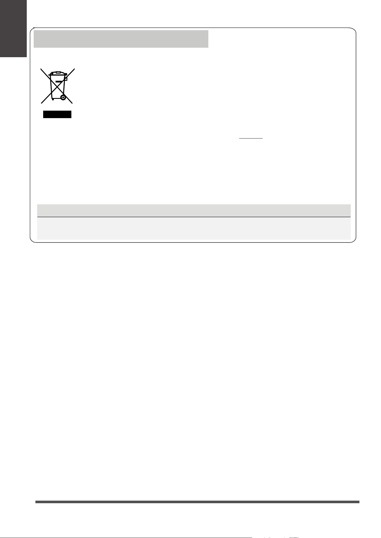
Correct Disposal of This Product
(Waste Electrical & Electronic Equipment)
This marking shown on the product or its literature, indicates that waste electrical and eletrical
equipment should not be mixed with general household waste.
Page 9
Unit Specifications and Features
Unit
Specifications
and Features
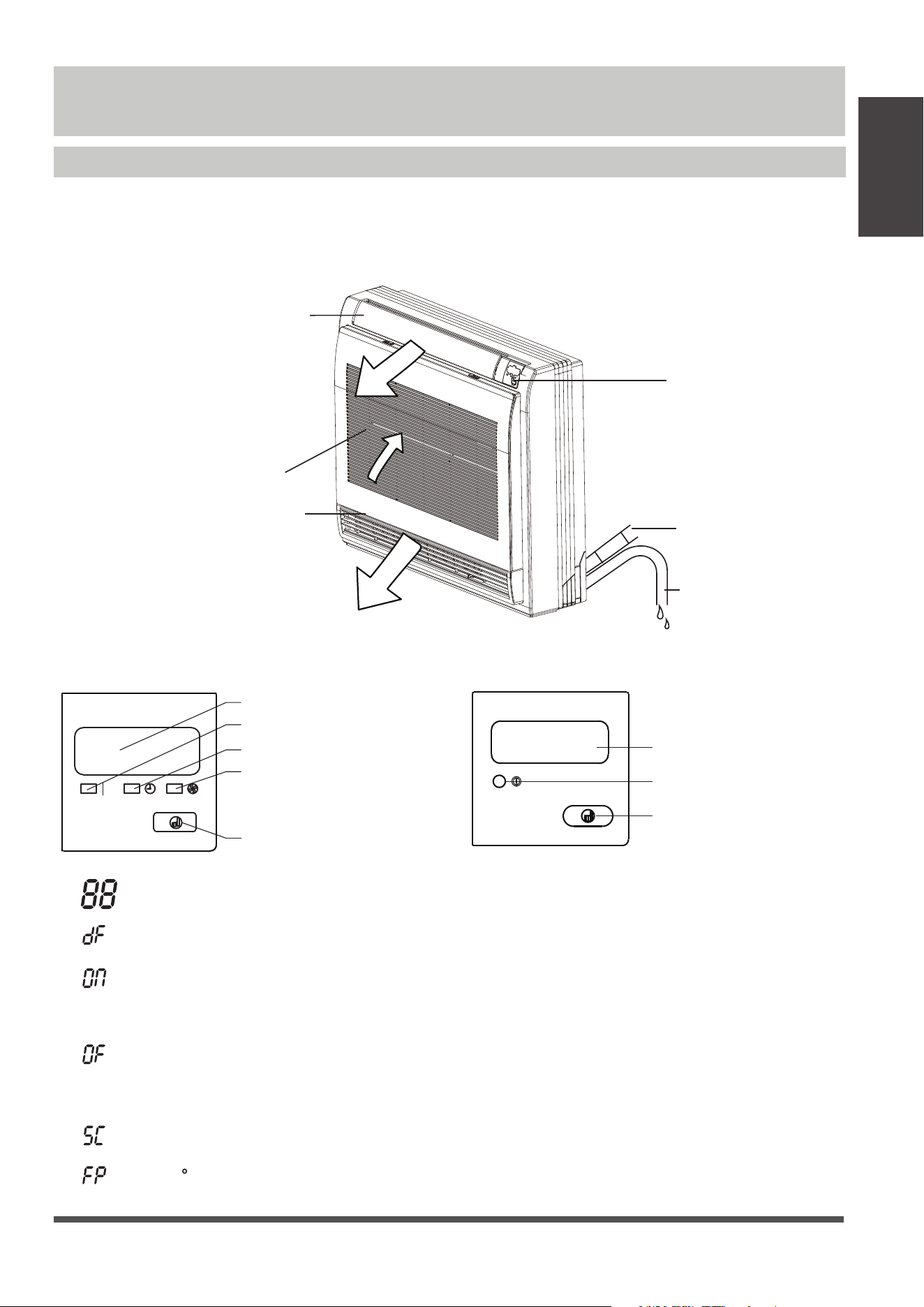
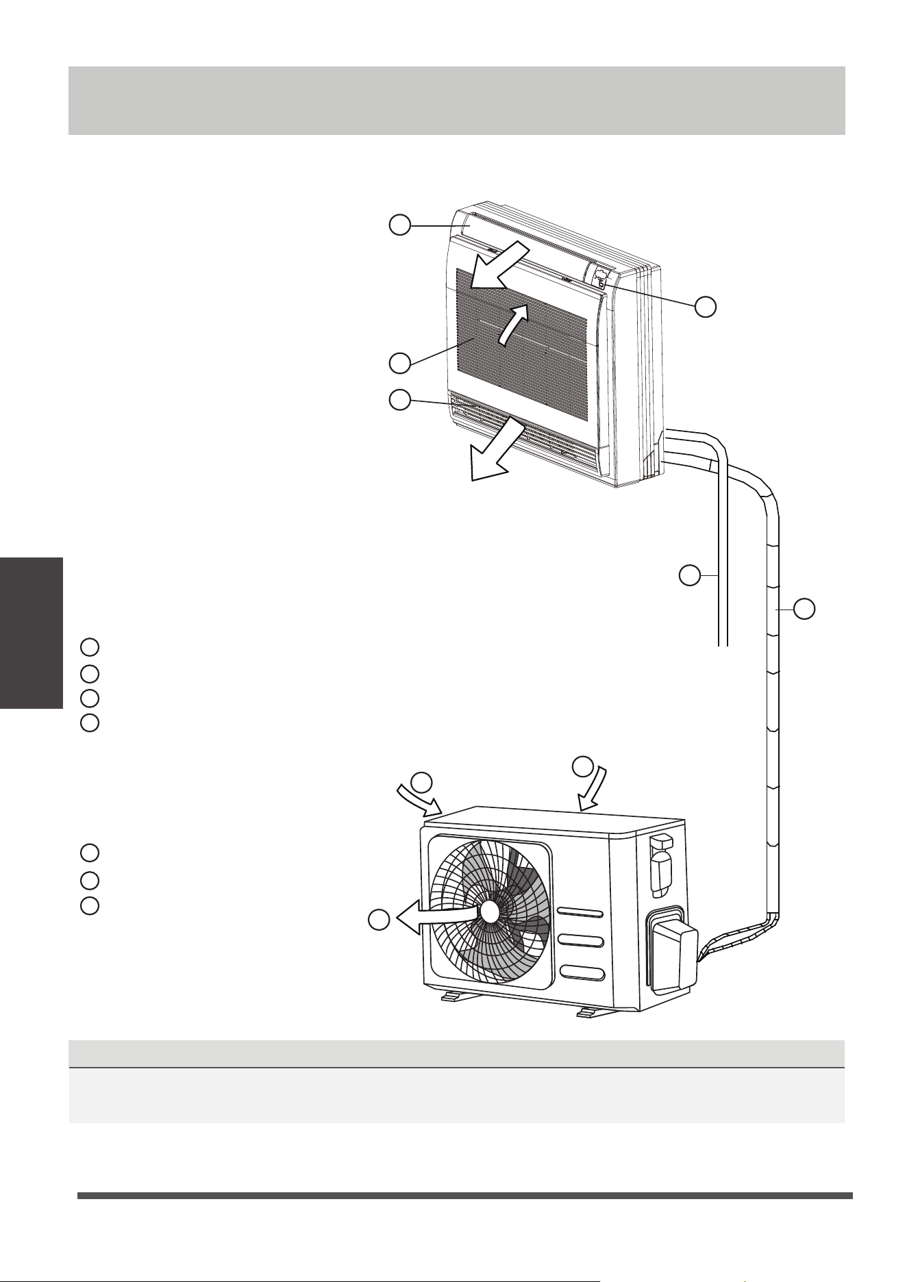
Indoor unit display
NOTE:
This display panel on the indoor unit can be used to operate the unit in case the remote control
has been misplaced or is out of batteries.
Drain hose
Refrigerant
connecting
pipe
Display panel
Air inlet (with air filter in it)
Air flow louver (at air outlet)
Air flow louver (at air outlet)
Display panel
MANUAL button: This button selects the mode
in the following order: AUTO, FORCED COOL, OFF.
FORCED COOL mode: In FORCED COOL mode,
the Operation light flashes. The system will then
turn to AUTO after it has cooled with a high wind
speed for 30 minutes. The remote control will be
disabled during this operation.
OFF mode: The unit turns o and the remote
control is re-enabled.
Infrared receiver
Timer indicator
PRE-DEF
(pre-heating/defrost)
indicator
Operation indicator
Manual button
Infrared receiver
Operation indicator
Manual button
(A) (B)
•
Displays temperature and Error codes:
“ ” when defrosting(for model B cooling &
heating units)
“ ” for 3 seconds when:
• TIMER ON is set(for model B)
• SWING or SILENCE is turned on
“ ” for 3 seconds when:
• TIMER OFF is set(for model B)
• SWING or SILENCE is turned o
“ ” when unit is self-cleaning
“ ” when 8 C heating feature is turned on
Unit
Specifications
and Features
Page 10
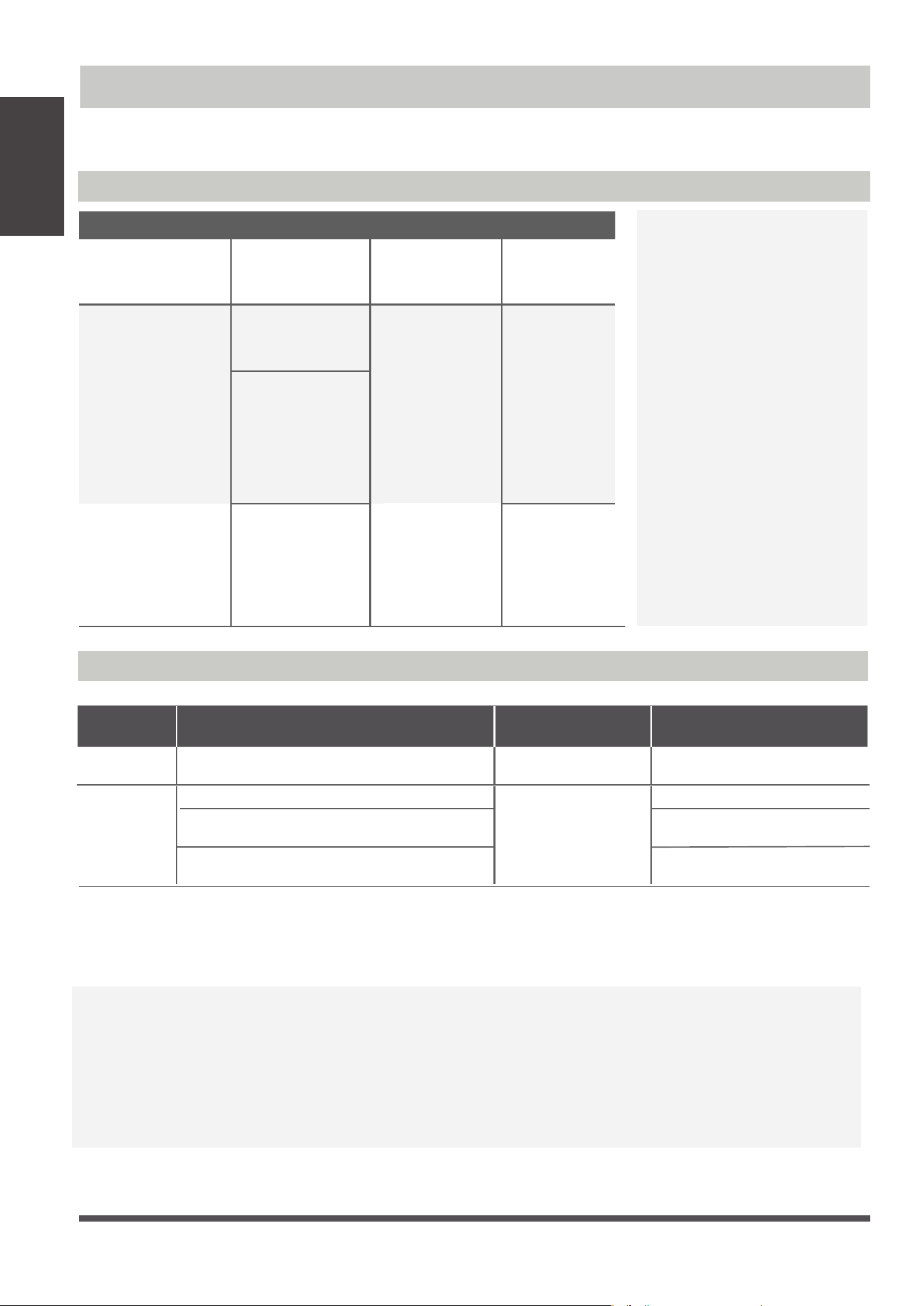
Operating temperature
When your air conditioner is used outside of the following temperature ranges, certain safety
protection features may activate and cause the unit to disable.
To further optimize the performance of your unit, do the following:
• Keep doors and windows closed.
• Limit energy usage by using TIMER ON and TIMER OFF functions.
• Do not block air inlets or outlets.
• Regularly inspect and clean air lters.
NOTE: Room relative humidity less than 80%. If the air conditioner operates in excess of this
gure, the surface of the air conditioner may attract condensation. Please sets the vertical air
ow louver to its maximum angle (vertically to the oor), and set HIGH fan mode.
Room
Temperature
62°F-90°F (17°C-32°C)
0°C-30°C
(32°F-86°F)
50°F-90°F (10°C-32°C)
Outdoor
Temperature
64°F-109°F (18°C-43°C)
(19°F-75°F)
-7°C-24°C
52°F-109°F (11°C-43°C)
19°F-109°F(-7°C-43°C)
(For models with low-temp cooling systems)
64°F-109°F (18°C-43°C)
64°F-126°F (18°C-52°C)
(For special tropical models)
64°F-126°F (18°C-52°C)
(For special tropical models)
COOL mode HEAT mode DRY mode
COOL mode
HEAT mode
DRY mode
Room Temperature
17°C - 32°C
(62°F - 90°F)
0°C - 30°C
(32°F - 86°F)
10°C - 32°C
(50°F - 90°F)
Outdoor
Temperature
0°C - 50°C
(32°F - 122°F)
(5°F - 75°F)
-15°C - 24°C
0°C - 50°C
(32°F - 122°F)
(32°F - 126°F)
0°C - 52°C
(For special
tropical models)
(32°F - 126°F)
0°C - 52°C
(For special
tropical models)
(5°F - 122°F)
-15°C - 50°C
(For models with
low temp.
cooling systems.)
Inverter Split Type
Fixed-speed Type
FOR OUTDOOR UNITS
WITH AUXILIARY
ELECTRIC HEATER
When outside
temperature is below
32°F (
0°C), we strongly
recommend keeping the
unit plugged in at all
time to ensure smooth
ongoing performance.

Unit
Specifications
and Features
Page 11
Other features
Default Setting (some models)
When the air conditioner restarts after a
power failure, it will default to the factory
settings (AUTO mode, AUTO fan, 76°F
(
24°C). This may cause inconsistencies on
the remote control and unit panel. Use
your remote control to update the status.
Auto-Restart (some models)
In case of power failure, the system will
immediately stop. When power returns,
the Operation light on the indoor unit will
flash. To restart the unit, press the ON/OFF
button on the remote control. If the system
has an auto restart function, the unit will
restart using the same settings.
Louver Angle Memory Function
(some models)
Some models are designed with a louver angle
memory function. When the unit restarts after a
power failure, the angle of the horizontal louvers
will automatically return to the previous position.
The angle of the horizontal louver should not be
set too small as condensation may form and drip
into the machine. To reset the louver, press the
manual button, which will reset the horizontal
louver settings.
Refrigerant Leak Detection System
(some models)
When the outdoor temperature is below
zero, the electric heating belt of the outdoor
unit chassis is used for ice melting, without
defrosting. (some models)
The indoor unit will automatically display “EC”
or “EL0C”or ash LEDS (model dependent )
when it detects refrigerant leakage.
Page 12
Unit
Specifications
and Features
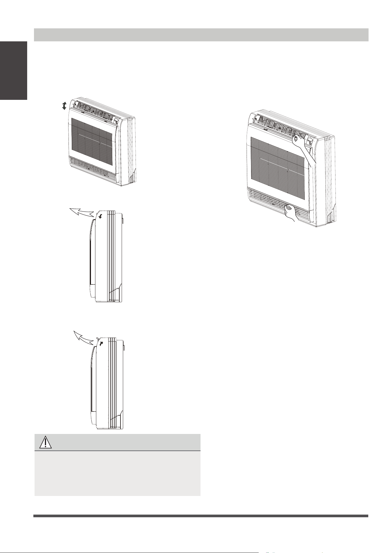
Adjusting Air Flow Direction
CAUTION
Do not try to adjust the horizontal louver by
hand. This may cause damage the
mechanism and result in condensation
forming on the air outlets.
Manual Swing: Press Air Direction to x the
louver at a desired angle.The louver swings
(upward or downward) at a dierent angle
with each press of the button.
When cooling
Adjust the louver downwards (horizontally).
When heating
Adjust the louver vertically.
Adjust the Air Flow Direction Left and
Right
Hold the knob and move the louver.
You will nd a knob on the left-side and the
right-side blades.
•
•
•
•
Page 13
Care and Maintenance
Cleaning Your Indoor Unit
BEFORE CLEANING OR
MAINTENANCE
ALWAYS TURN OFF YOUR AIR CONDITIONER
SYSTEM AND DISCONNECT ITS POWER SUPPLY
BEFORE CLEANING OR MAINTENANCE.
CAUTION
Only use a soft, dry cloth to wipe the unit clean.
If the unit is especially dirty, you can use a cloth
soaked in warm water to wipe it clean.
•
Do not
use chemicals or chemically treated
cloths to clean the unit
•
Do not use benzene, paint thinner,
polishing powder or other solvents to clean
the unit. They can cause the plastic surface
to crack or deform.
•
Do not use water hotter than 40°C (104°F)
to clean the front panel. This can cause the
panel to deform or become discolored.
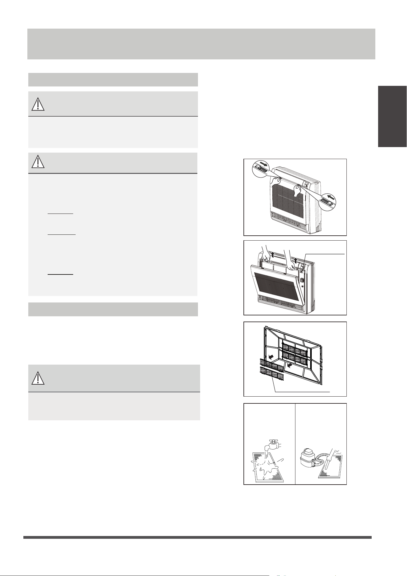
Cleaning Your Air Filter
A clogged air conditioner can reduce the cooling
efficiency of your unit, and can also be bad for
your health. Make sure to clean the filter once
every two weeks.
WARNING: DO NOT REMOVE OR
CLEAN THE FILTER BY YOURSELF
Removing and cleaning the filter can be
dangerous. Removal and maintenance must be
performed by a certified technician.
Care and
Maintenance
1. Open the front panel.
2. Remove the air lter.
Press the claws on the right and left sides of
the air lter down slightly, then pull upward.
5.
Rinse the lter with clean water and allow
it to air-dry.
DO NOT
let the lter dry in
direct sunlight.
6. Reinstall the lter.
3.
Hold the tabs of the frame,and remove the
4 claws. (The special function lter can be
washed with water once every 6 months. It
isrecommended that you replace it once
every 3 years.)
4.
Clean the air lter by vacuuming the surface
or washing it in warm water with mild
detergent.
Air Outlet
Selection Switch
Special function lter
If using a vacuum
cleaner, the inlet
side should face
the vacuum.
If using water, the
inlet side should
face down and
away from the
water stream.
Page 14
Care and
Maintenance
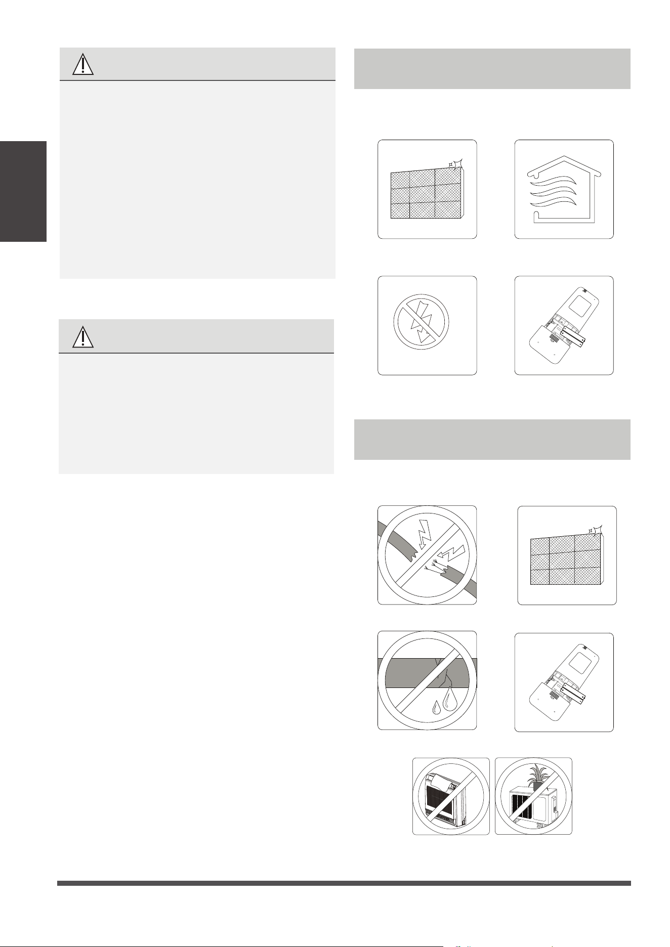
Maintenance –
Long Periods of Non-Use
If you plan not to use your air conditioner for an
extended period of time, do the following:
Clean all lters
Turn on FAN function until
unit dries out completely
Turn o the unit and
disconnect the power
Remove batteries
from remote control
Maintenance –
Pre-Season Inspection
After long periods of non-use, or before periods
of frequent use, do the following:
Check for damaged wires Clean all lters
Check for leaks Replace batteries
Make sure nothing is blocking all air inlets and outlets
CAUTION
•
Before changing the lter or cleaning,
tu
rn o
the unit and disconnect its power
suppl
y.
•
When removing lter, do not touch metal
parts in the unit. The sharp metal edges can
cut you.
•
Do not use water to clean the inside of the
indoor unit. This can dest
r
oy insulation and
cause electrical shock.
•
Do not expose lter to direct sunlight when
drying. This can shrink the lte
r.
CAUTION
•
Any maintenance and cleaning of outdoor
unit should be performed by an authorized
dealer or a licensed service p
rovider.
•
Any unit repairs should be performed
by an authorized dealer or a licensed
service provider.
Page 15
Troubleshooting
Common Issues
The following problems are not a malfunction and in most situations will not require repairs.
Issue Possible Causes
Unit does not turn
on when pressing
ON/OFF button
The Unit has a 3-minute protection feature that prevents the unit from overloading.
The unit cannot be restarted within three minutes of being turned o.
The unit may change its setting to prevent frost from forming on the unit.
Once the temperature increases, the unit will start operating in the
previously selected mode again.
The set temperature has been reached, at which point the unit turns o the
compressor. The unit will continue operating when the temperature
fluctuates again.
The indoor unit
emits white mist
In humid regions, a large temperature dierence between the room’s air
and the conditioned air can cause white mist.
Both the indoor and
outdoor units emit
white mist
When the unit restarts in HEAT mode after defrosting, white mist may be
emitted due to moisture generated from the defrosting process.
Troubleshooting
The unit changes from
COOL mode to
FAN mode
The indoor unit makes
noises
A squeaking sound may occur after running the unit in HEAT mode due to
expansion and contraction of the unit’s plastic parts.
Both the indoor unit
and outdoor unit make
noises
Low hissing sound during operation: This is normal and is caused by refrigerant
gas flowing through both indoor and outdoor units.
Low hissing sound when the system starts, has just stopped running, or is
defrosting: This noise is normal and is caused by the refrigerant gas stopping or
changing direction.
Squeaking sound: Normal expansion and contraction of plastic and metal parts
caused by temperature changes during operation can cause squeaking noises.
SAFETY PRECAUTIONS
If any of the following conditions occurs, turn o your unit immediately!
• The power cord is damaged or abnormally warm
• You smell a burning odor
• The unit emits loud or abnormal sounds
• A power fuse blows or the circuit breaker frequently trips
• Water or other objects fall into or out of the unit
DO NOT ATTEMPT TO FIX THESE YOURSELF! CONTACT AN AUTHORIZED
SE
RVICE PROVIDER IMMEDIATELY!
Cooling and Heating Models: If the Operation light and PRE-DEF (Pre-heating/
Defrost) indicators are lit up, or the Operation light is lit up and the LCD screen
display “dF”, the outdoor temperature is too cold and the unit’s anti-cold wind
is activated in order to defrost the unit.
A squeaking sound is heard when the system is OFF or in COOL mode. The
noise is also heard when the drain pump (optional) is in operation.
Page 16
Troubleshooting
Issue Possible Causes
The outdoor unit
makes noises
The unit will make dierent sounds based on its current operating mode.
Dust is emitted from
either the indoor or
outdoor unit
The unit may accumulate dust during extended periods of non-use, which will be
emitted when the unit is turned on. This can be mitigated by covering the unit during
long periods of inactivity.
The unit emits a
bad odor
The unit may absorb odors from the environment (such as furniture, cooking,
cigarettes, etc.) which will be emitted during operations.
The unit’s filters have become moldy and should be cleaned.
The fan of the outdoor
unit does not operate
During operation, the fan speed is controlled to optimize product operation.
NOTE:
If problem persists, contact a local dealer or your nearest customer service center. Provide
them with a detailed description of the unit malfunction as well as your model number.
Troubleshooting
When troubles occur, please check the following points before contacting a repair company.
Problem Possible Causes Solution
Poor Cooling
Performance
Temperature setting may be higher
than ambient room temperature
Lower the temperature setting
The heat exchanger on the indoor
or outdoor unit is dirty
Clean the aected heat exchanger
The air lter is dirty
Remove the filter and clean it according to
instructions
The air inlet or outlet of either
unit is blocked
Turn the unit o, remove the obstruction
and turn it back on
Doors and windows are open
Make sure that all doors and windows are
closed while operating the unit
Excessive heat is generated
by sunlight
Close windows and curtains during periods
of high heat or bright sunshine
Too many sources of heat in the
room (people, computers,
electronics, etc.)
Reduce amount of heat sources
Low refrigerant due to leak
or long-term use
Check for leaks, re-seal if necessary and
top o refrigerant
Page 17
Troubleshooting
Problem Possible Causes Solution
The unit is not
working
Power failure
Wait for the power to be restored
The power is turned o Turn on the power
The fuse is burned out
Replace the fuse
Remote control batteries are dead
Replace batteries
The Unit’s 3-minute protection
has been activated
Wait three minutes after restarting
the unit
Timer is activated
Turn timer o
The unit starts and
stops frequently
There’s too much or too little
refrigerant in the system
Check for leaks and recharge the
system with refrigerant.
Incompressible gas or moisture
has entered the system.
Evacuate and recharge the system
with refrigerant
The compressor is broken Replace the compressor
The voltage is too high or
too low
Install a manostat to regulate the
voltage
Poor heating
performance
The outdoor temperature is
extremely low
Use auxiliary heating device
Cold air is entering through
doors and windows
Make sure that all doors and
windows are closed during use
Low refrigerant due to leak or
long-term use
Check for leaks, re-seal if necessary
and top o refrigerant
Indicator lamps
continue flashing
The unit may stop operation or continue to run safely. If the indicator
lamps continue to flash or error codes appear, wait for about 10
minutes. The problem may resolve itself.
If not, disconnect the power, then connect it again. Turn the unit on.
If the problem persists, disconnect the power and contact your nearest
customer service center.
Error code appears and
begins with the letters
as the following in the
window display of
indoor unit:
E(x), P(x), F(x)
EH(xx), EL(xx), EC(xx)
PH(xx), PL(xx), PC(xx)
•
•
•
NOTE:
If your problem persists after performing the checks and diagnostics above,
turn o your unit immediately and contact an authorized service center.
System circuit is blocked
Determine which circuit is blocked and
replace the malfunctioning piece of
equipment
Page 18
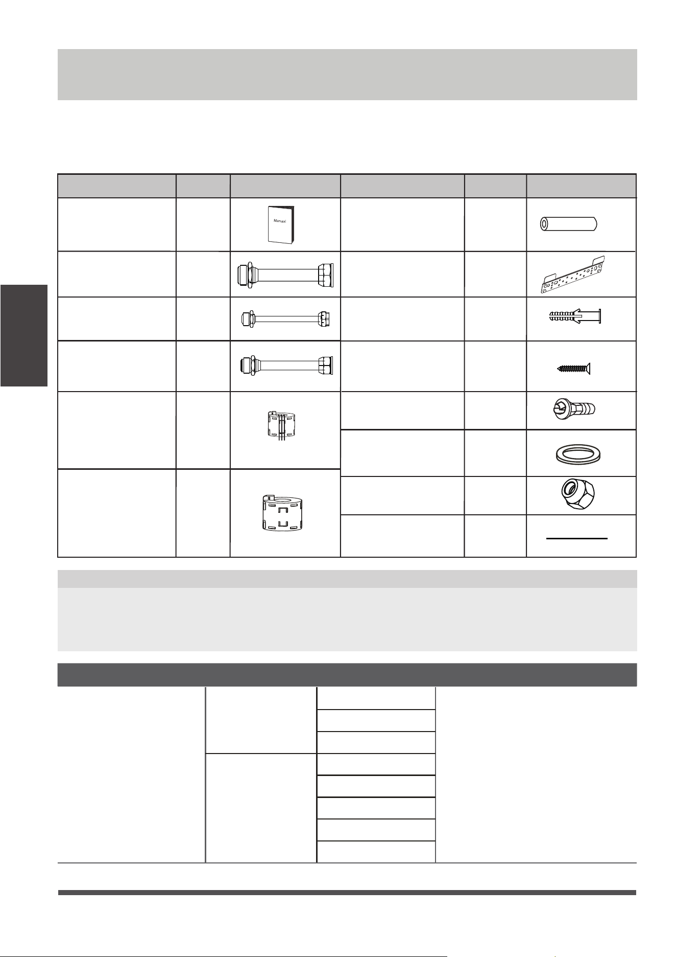
Accessories
Name
Shape Quantity(PC)
Manual
Parts you must purchase
separately. Consult the dealer
about the proper pipe size of
the unit you purchased.
Connecting pipe
assembly
Liquid side
Gas side
1/4 in ( 6.35)
3/8in ( 9.52)
1/2in (12.7)
3/8in (9.52 )
1/2in (12.7 )
5/8in ( 16)
3/4in ( 19)
7/8in ( 22)
2~4
1
Name of Accessories
Q‘ty(pc)
Shape
1
1
1
1
1
1
1
Name of Accessories
Q‘ty(pc)
Shape
Transfer connector
(Φ
Φ
12.7-Φ
Φ
15.9)
(some models)
Transfer connector
(Φ
Φ
6.35-Φ
Φ
9.52)
(some models)
Transfer connector
(Φ
Φ
9.52-Φ
Φ
12.7)
(some models)
Drain joint
(some models)
Seal ring
(some models)
Magnetic ring (wrap
the electric wires S1
& S2 ( P & Q & E )
around the magnetic
ring twice)
(some models)
Magnetic ring (Hitch
it on the connective
cable between indoor
unit and outdoor unit
after installation.)
(some models)
S1&S2(P&Q&E)
Copper nut
2
Accessories
Soundproof / insulation
sheath (some models)
2
1
Red short connected
wire (some models)
The air conditioning system comes with the following accessories. Use all of the installation parts and
accessories to install the air conditioner. Improper installation may result in water leakage, electrical
shock and re, or cause the equipment to fail. The items are not included with the air conditioner must
be purchased separately.
Optional accessories
There are two types of remote controls: wired and wireless.
Select a remote controller based on customer preferences and requirements and install in an
appropriate place.
Refer to catalogues and technical literature for guidance on selecting a suitable remote controller.
•
Mounting plate
Mounting plate
fixing screw
Anchor
6
(depending
on models)
6
(depending
on models)
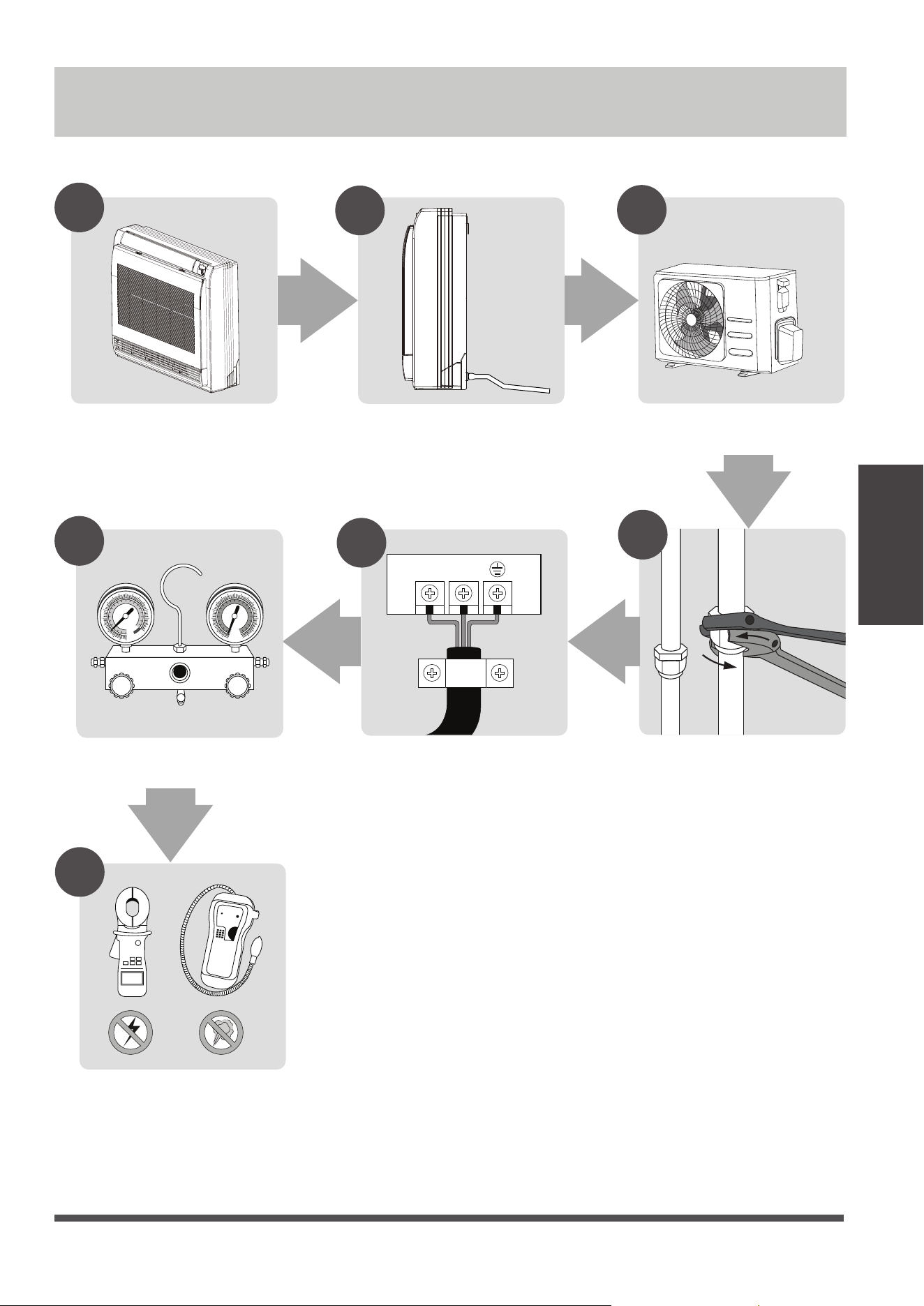
Install the drainpipe
Install the outdoor unit
L(L1) N(L2)
1
2
3
4
5
MC MC
6
7
Install the indoor unit
Evacuate the refrigeration
system
Connect the wires Connect the refrigerant
pipes
Perform a test run
Page 19
Installation Summary
Installation Summary
Page 20
Unit Parts
NOTE ON ILLUSTRATIONS
Illustrations in this manual are for explanatory purposes. The actual shape of your indoor
unit may be slightly dierent. The actual shape shall prevail.
NOTE: The installation must be performed in accordance with the requirement of local and
national standards. The installation may be slightly dierent in dierent areas.
Unit Parts
Display panel
Drain pipe
Connecting pipe
Air inlet
Air outlet
Air ow louver (at air outlet)
Air inlet (with air lter in it)
1
1
2
3
4
5
6
6
7
1
2
3
4
5
6
7
Page 21
Indoor Unit
Installation
Installation Instructions – Indoor unit
Step 1: Select installation location
Before installing the indoor unit, you must
choose an appropriate location. The following
are standards that will help you choose an
appropriate location for the unit.
Proper installation locations meet the
following standards:
Indoor Unit Installation
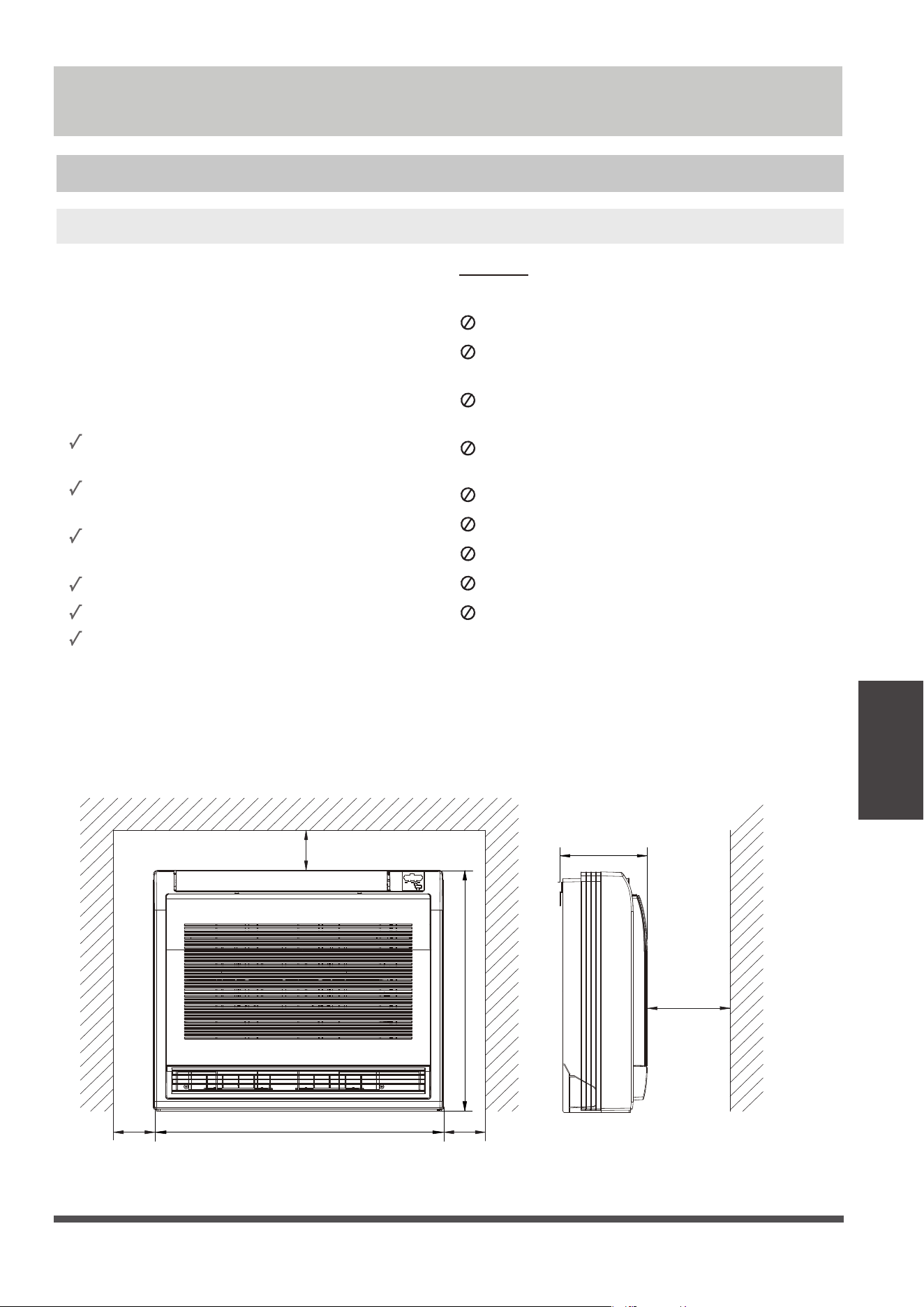
Recommended distances between the indoor unit
The distance between the mounted indoor unit should meet the specications illlustrated in the
following diagram.
NOTE: Panel installation should be performed after piping and wiring have been completed.
Enough room exists for installation and
maintenance.
Enough room exists for the connecting the
pipe and drainpipe.
The ceiling is horizontal and its structure can
sustain the weight of the indoor unit.
The air inlet and outlet are not blocked.
The airflow can fill the entire room.
There is no direct radiation from heaters.
DO NOT
install unit in the following
locations:
Areas with oil drilling or fracking
Coastal areas with high salt content in the
air
Areas with caustic gases in the air, such as
hot springs
Areas that experience power uctuations,
such as factories
Enclosed spaces, such as cabinets
Kitchens that use natural gas
Areas with strong electromagnetic waves
Areas that store flammable materials or gas
Rooms with high humidity, such as
bathrooms or laundry rooms
39.7in
8.2in
27.5in
≥3.9in
3.9in 3.9in
23 in
Page 22
Indoor Unit
Installation
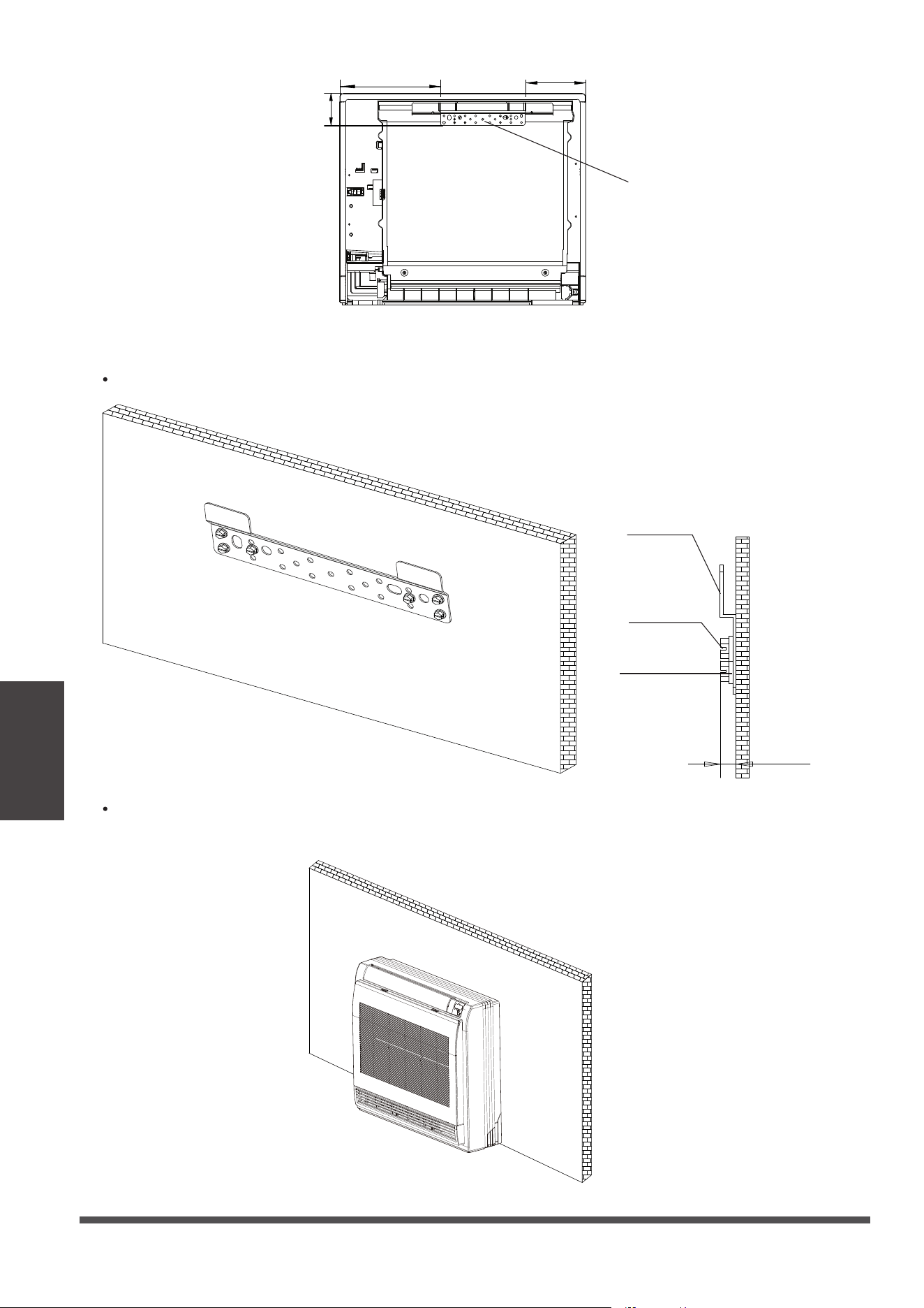
Step 2: Installing the main body
Fix the mounting plate with a tapping screw onto the wall.
Mounting plate
Tapping
screw
Washer
<
.23in
Hang the indoor unit on the mounting plate.
(The bottom of body can touch the oor or remain suspended, but the body must be installed
vertically.)
Mounting plate
6.8in
3.7in
11.2in
Page 23
Indoor Unit
Installation
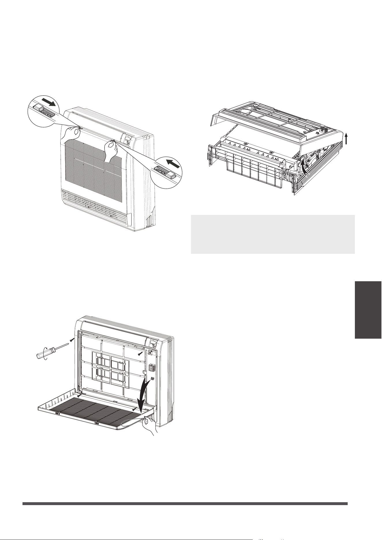
Step 3: Taking the indoor unit apart to
connect the pipes
1. Open the front panel
2. Remove the front panel.
NOTE: All the gures in this manual are for
demonstration purposes only. The air conditioner
you have purchased may be slightly dierent in
design, though similar in shape.
Slide the two stoppers on the left and right
sides inward until they click.
3. Remove the face plate.
Remove the four screws.
Open the bottom of the face plate at a
30-degree angle. Lift the top of the face
plate.
Remove the string.
Allow the front panel to fall forward and
remove it.
Indoor Unit
Installation
Page 24
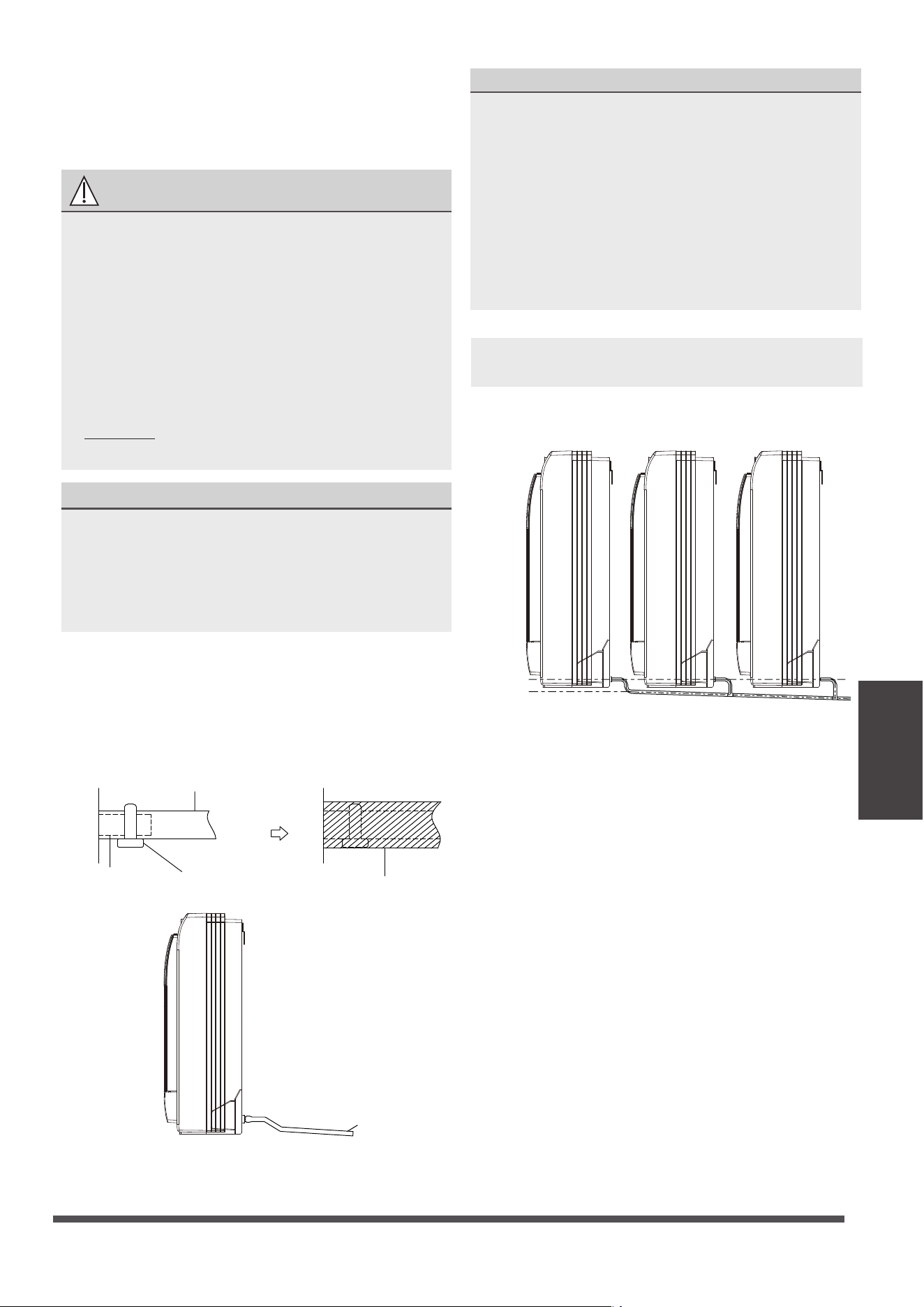
Step 5:
Drill wall hole for connective piping
1. Determine the location of the wall hole based
on the location of the outdoor unit.
2. Using a 2.5in (65mm) or 3.54in (90mm)
(depending on models )core drill, drill a
hole in the wall. Make sure that the hole
is drilled at
a slight downward angle, so
that the outdoor end of the hole is lower than
the indoor end by about 0.5in (12mm).
This will ensure proper water drainage.
3. Place the protective wall cuff in the hole. This
protects the edges of the hole and will help
seal it when you finish the installation process.
CAUTION
When drilling the wall hole, make sure to
avoid wires, plumbing, and other sensitive
Wall
IndoorOutdoor
≈ 0.5 inch/12mm
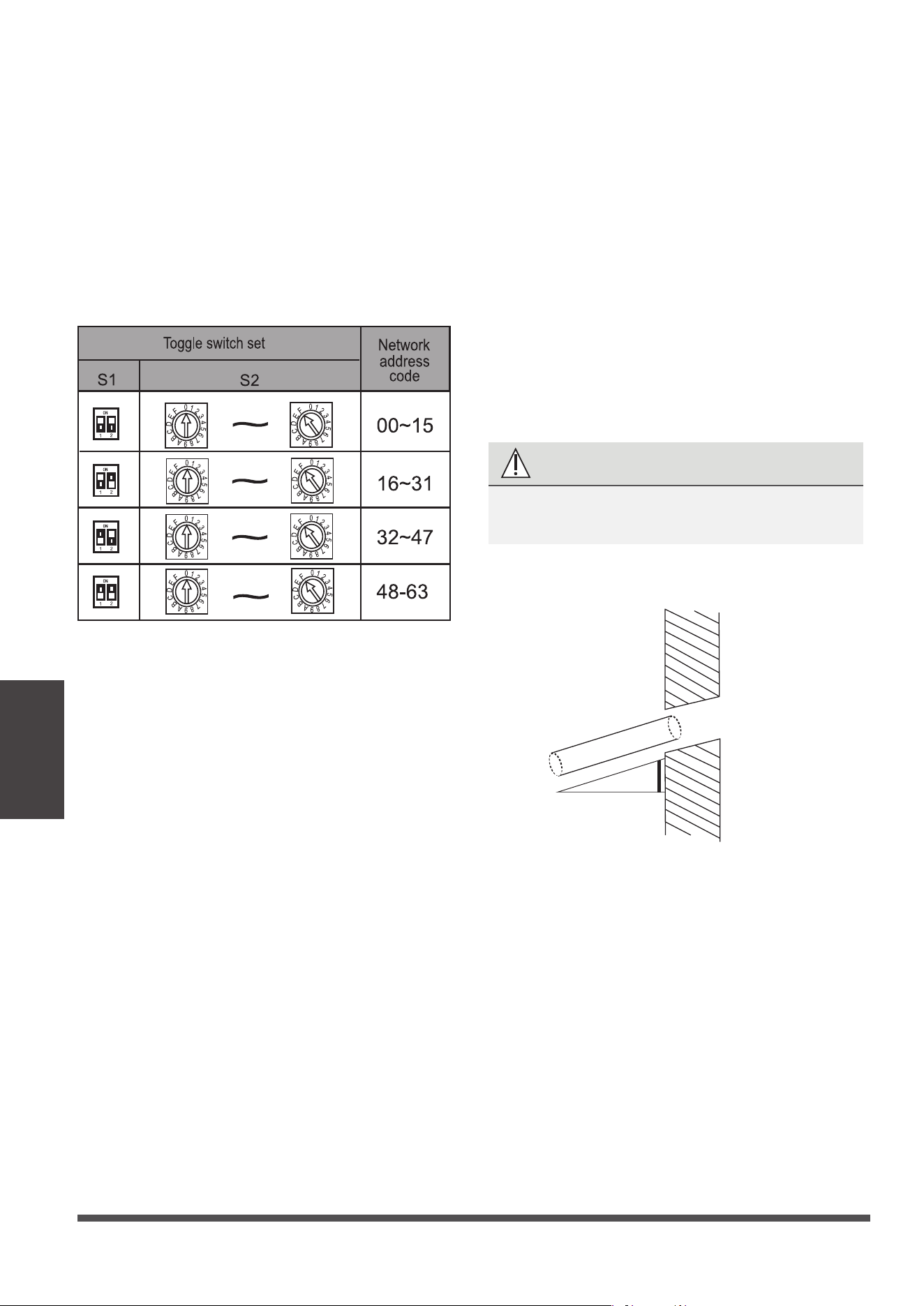
Step 4: Network address set (some models)
(Only unit of 18000Btu/h has the function that
Network address set.)
Every air-conditioner in network has only one
network address to distinguish each other.
Address code of air-conditioner in LAN is set by
code switches S1 & S2 on the Main Control Board
of the indoor unit, and the set range is 0-63.
Page 25
Indoor Unit
Installation
Step 6: Connect drain hose
NOTE ON DRAINPIPE INSTALLATION
•
When using an extended drainpipe, tighten
the indoor connection with an additional
protection tube. This prevents it from
pulling loose.
• The drainpipe should slope downward at a
gradient of at least 1/100 to prevent water
from flowing back into the air conditioner.
•
The drainpipe is used to drain water away from
the unit. Improper installation may cause unit
and property damage.
•
Insulate all piping to prevent condensation,
which could lead to water damage.
• If the drainpipe is bent or installed
incorrectly, water may leak and cause a
water-level switch malfunction.
• In HEAT mode, the outdoor unit will
discharge water. Ensure that the drain hose
is placed in an appropriate area to avoid
water damage and slippage.
• DO NOT pull the drainpipe forcefully. This
could disconnect it.
NOTE ON PURCHASING PIPES
Installation requires a polyethylene tube
(exterior diameter = 1.4 -1.53in (7-3.9cm),
interior diameter = 1.25in (3.2cm), which can
be obtained at your local hardware store or
dealer.
1.
2.
Drainpipe
connecting port
Drain hose
Pipe clasp
Insulation
Cover the drainpipe with heat insulation to
prevent condensation and leakage.
Attach the mouth of the drain hose to the
unit’s outlet pipe. Sheath the mouth of the
hose and clip it rmly with a pipe clasp.
NOTE: When connecting multiple drainpipes,
install the pipes as illustrated.
Incorrect installation could cause water to
flow back into the unit and flood.
(4”)
Lean over 1/100
CAUTION
Page 26
Outdoor Unit
Installation
Installation Instructions – Outdoor unit
Step 1: Select installation location
Before installing the outdoor unit, you must
choose an appropriate location. The following are
standards that will help you choose an appropriate
location for the unit.
Proper installation locations meet the
following standards:
Meets all spatial requirements shown in
Installation Space Requirements above.
Good air circulation and ventilation
Firm and solid—the location can support the
unit and will not vibrate
Noise from the unit will not disturb others
Install the unit by following local codes and
regulations , there may be dier slightly
between dierent regions.
SPECIAL CONSIDERATIONS FOR EXTREME
WEATHER
If the unit is exposed to heavy wind:
Install unit so that air outlet fan is at a 90°
angle to the direction of the wind. If needed,
build a barrier in front of the unit to protect it
from extremely heavy winds.
See Figures below.
Strong
wind
Strong wind
Strong wind
If the unit is frequently exposed to heavy
rain or snow:
Build a shelter above the unit to protect
it from the rain or snow. Be careful not to
obstruct air flow around the unit.
If the unit is frequently exposed to salty air
(seaside):
Use outdoor unit that is specially designed to
resist corrosion.
Wind Baffle
Protected from prolonged periods of direct
sunlight or rain
DO NOT
install unit in the following locations:
Near an obstacle that will block air inlets
and outlets
Near a public street, crowded areas, or
where noise from the unit will disturb others
Near animals or plants that will be harmed
by hot air discharge
Near any source of combustible gas
In a location that is exposed to large
amounts of dust
In a location exposed to a excessive amounts
of salty air
Where snowfall is anticipated, raise the
unit above the base pad to prevent ice
buildup and coil damage. Mount the unit
high enough to be above the average
accumulated area snowfall. The minimum
height must be 18 inches
Outdoor Unit Installation
24in (60cm)
on righ
t
12in (30cm)
on le
79in (200cm)
in fron
t
m back w
12in (30cm)
fro all
24in (60cm) above
Page 27
Indoor Unit
Outdoor Unit
Installation
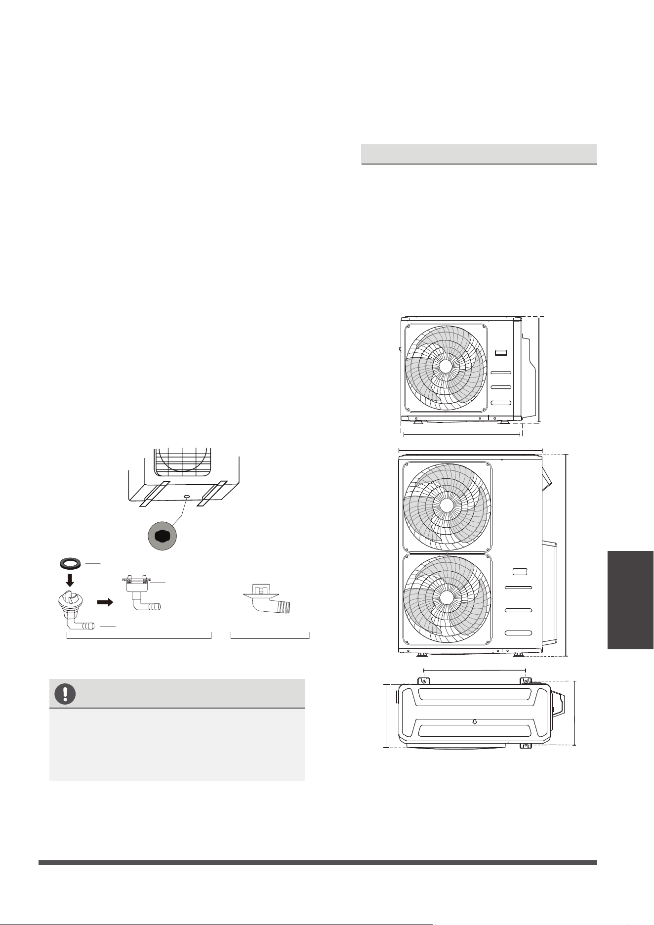
Step 2: Install drain joint(Heat pump unit only)
Before bolting the outdoor unit in place, you must
install the drain joint at the bottom of the unit.
Note that there are two dierent types of drain
joints depending on the type of outdoor unit.
If the drain joint comes with a rubber seal
(see Fig. A ), do the following:
1.
Fit the rubber seal on the end of the drain joint
that will connect to the outdoor unit.
2.
Insert the drain joint into the hole in the base
pan of the unit.
3.
Rotate the drain joint 90° until it clicks in place
facing the front of the unit.
4.
Connect a drain hose extension (not included)
to the drain joint to redirect water from the
unit during heating mode.
If the drain joint doesn’t come with a rubber
seal (see Fig. B ), do the following:
1.
Insert the drain joint into the hole in the base
pan of the unit. The drain joint will click in
place.
2.
Connect a drain hose extension (not included)
to the drain joint to redirect water from the
unit during heating mode.
Seal
Drain joint
(A) (B)
Base pan hole of
outdoor unit
Seal
IN COLD CLIMATES
In cold climates, make sure that the drain hose
is as vertical as possible to ensure swift water
drainage. If water drains too slowly, it can
freeze in the hose and ood the unit.
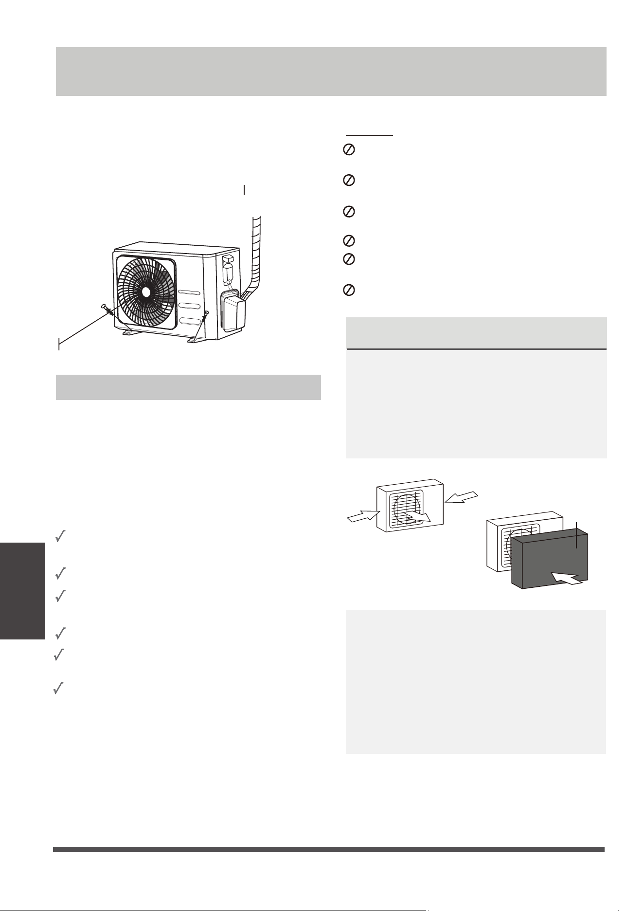
The outdoor unit can be anchored to the
ground or to a wall-mounted bracket with
bolt(M10). Prepare the installation base of the
unit according to the dimensions below.
Step 3: Anchor outdoor unit
UNIT MOUNTING DIMENSIONS
The following is a list of dierent outdoor
unit sizes and the distance between their
mounting feet. Prepare the installation base
of the unit according to the dimensions
below.
Split Type Outdoor Unit
A
B
D
W
H
W
H
Outdoor Unit Types and Specifications
Page 28
(unit: in/mm)
Outdoor Unit Dimensions
W x H x D
Mounting Dimensions
Distance A Distance B
29.9x23.2x11.2 (760x590x285) 20.85 (530) 11.4 (290)
31.9x22x12.2 (810x558x310) 21.6 (549) 12.8 (325)
33.27x27.5x12.6 (845x700x320) 22 (560) 13.2 (335)
35.4x33.85x12.4 (900x860x315) 23.2 (590) 13.1 (333)
37.2x31.9x15.55 (945x810x395) 25.2 (640) 15.95 (405)
38.98x38x13.58 (990x965x345) 24.58 (624) 14.4 (366)
37.24x31.9x16.53 (946x810x420) 26.5 (673)
15.87 (403)
37.24x31.9x16.14 (946x810x410) 26.5 (673)
15.87 (403)
37.5x52.5x16.14 (952x1333x410) 24.96 (634)
15.9 (404)
35x26.5x13.46 (890x673x342) 26.1 (663)
13.94 (354)
37.5x52.5x16.34 (952x1333x415)
24.96 (634)
15.9 (404)
33.27x27.6x14.3 (845x702x363)
21.26 (540)
13.8 (350)
36.93x53.9x15.43 (938x1369x392) 24.96 (634) 15.9 (404)
35.4x46x13.8 (900x1170x350) 23.2 (590) 14.88 (378)
31.5x21.8x13.1 (800x554x333) 20.24 (514) 13.39 (340)
30.7x21.25x9.85 (780x540x250) 21.6 (549) 10.85 (276)
30.3x21.85x11.8 (770x555x300) 19.2 (487) 11.7 (298)
Outdoor Unit
Installation
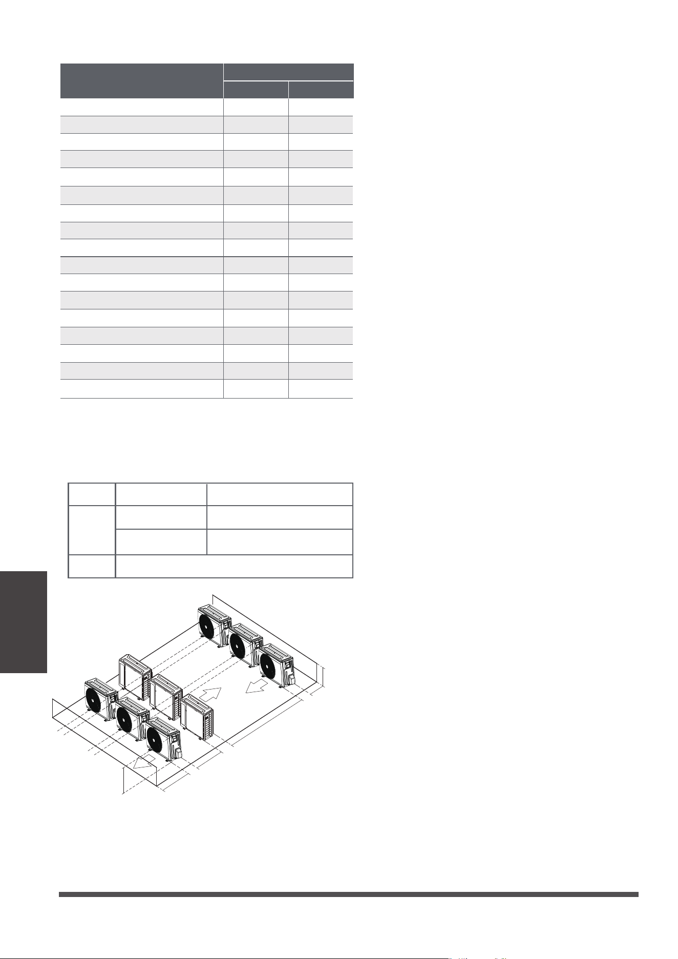
Rows of series installation
L ≤ H
L ≤ 1/2H
L A
9.8” / 25 cm or more
1/2H < L ≤ H
11.8” /30 cm or more
L > H
Can not be installed
The relations between H, A and L are as follows.
L
H
118”/ 300 cm or more
A
23.6”/60 cm
or more
59”/150 cm
or more
9.8"
/
25cm
or more
9.8"
/
25cm
or more
Page 29
Refrigerant piping
Connection
Note on Pipe Length
When connecting refrigerant piping, do not
let substances or gases other than the specied
refrigerant enter the unit. The presence of other gases or substances will lower the unit’s capacity,
and can cause abnormally high pressure in the refrigeration cycle. This can cause explosion and
injury.
Refrigerant Piping Connection
Ensure that the length of the refrigerant pipe, the number of bends, and the drop height
between the i
ndoor and outdoor units meets the requirements shown in the following table :
The Maximum Length And Drop Height Based on Models. (Unit: ft/m.)
Type of model Capacity (Btu/h) Length of piping Maximum drop height
North America,
Australia and the
eu frequency
conversion Split
Type
<15K
82/25 32.8/10
≥15K - <24K
98.4/30 65.6/20
≥24K - <36K
164/50 82/25
≥36K - ≤60K
213/65 98.4/30
Other Split Type
12K
49/15 26/8
18K-24K
8225 49/15
30K-36K
98.430 65.6/20
42K-60K
164/50 98.4/30
Liquid side
Indoor
Outdoor
Liquid side
Indoor
Outdoor
X
Liquid side
Indoor
Outdoor
X
CAUTION
Mark the data plate with the Orifice installed (for some models).
Please purchase the ttings according to the requirements in the manual strictly.
Refer the diagram when installing.
Page 30
Refrigerant piping
Connection
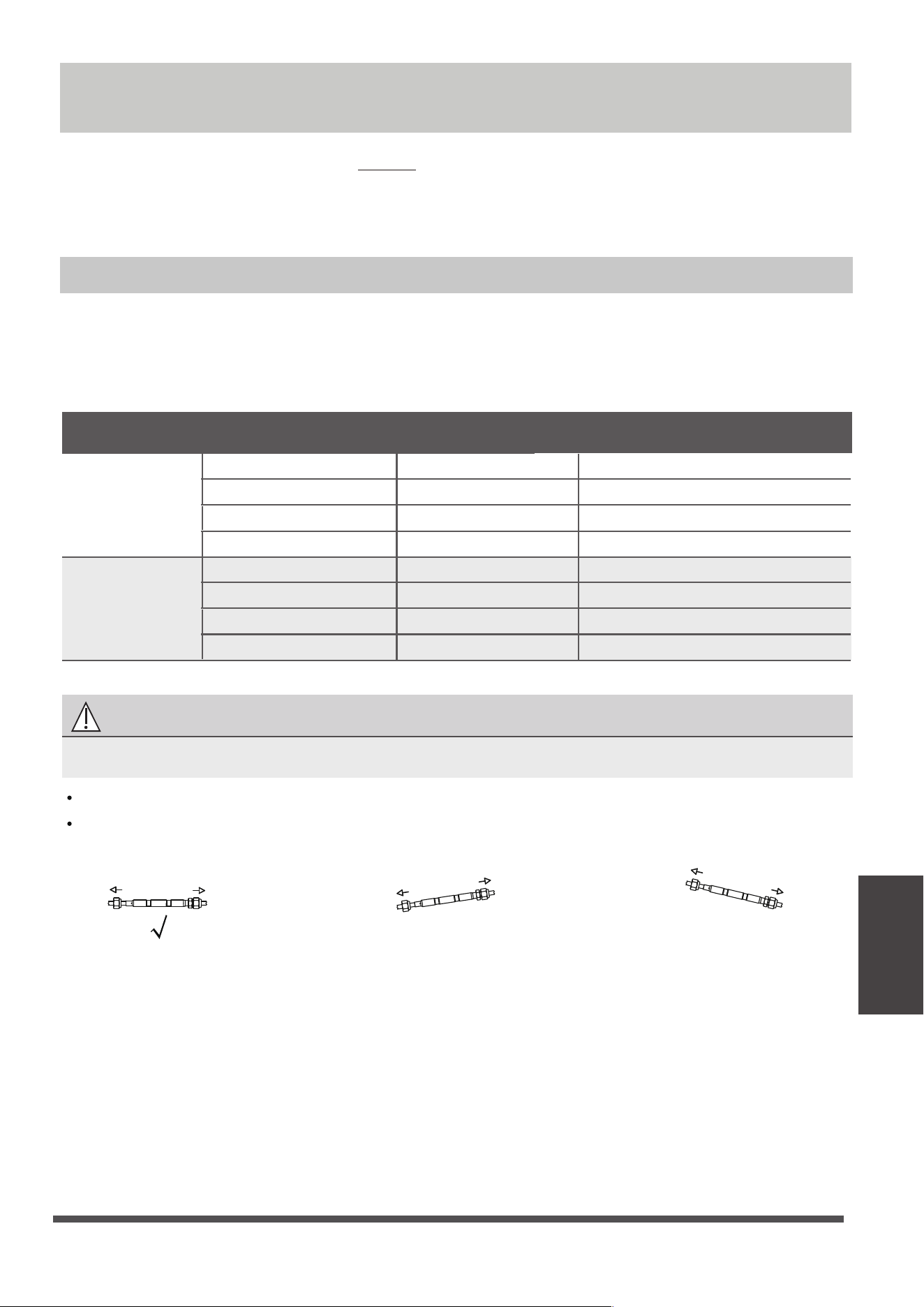
CAUTION
An oil trap should be installed every
20ft (6m) of vertical suction line riser
(
<36000Btu/h unit).
An oil trap should be installed every
10m(32.8ft) of vertical suction line riser
(≥36000Btu/h unit).
32.8ft /10m
(≥36000Btu/h unit)
20ft/6m
(<36000Btu/h unit)
32.8ft /10m
(≥36000Btu/h unit)
20ft/6m
(<36000Btu/h unit)
Indoor unit/
Outdoor unit
Indoor unit/
Outdoor unit
2. Using a pipe cutter, cut the pipe a little longer
than the measured distance.
3. Make sure that the pipe is cut at a perfect 90°
angle.
Oblique Rough Warped
90°
DO NOT DEFORM PIPE
WHILE CUTTING
Be extra careful not to damage, dent, or
deform the pipe while cutting. This will
drastically reduce the heating eciency
of the unit.
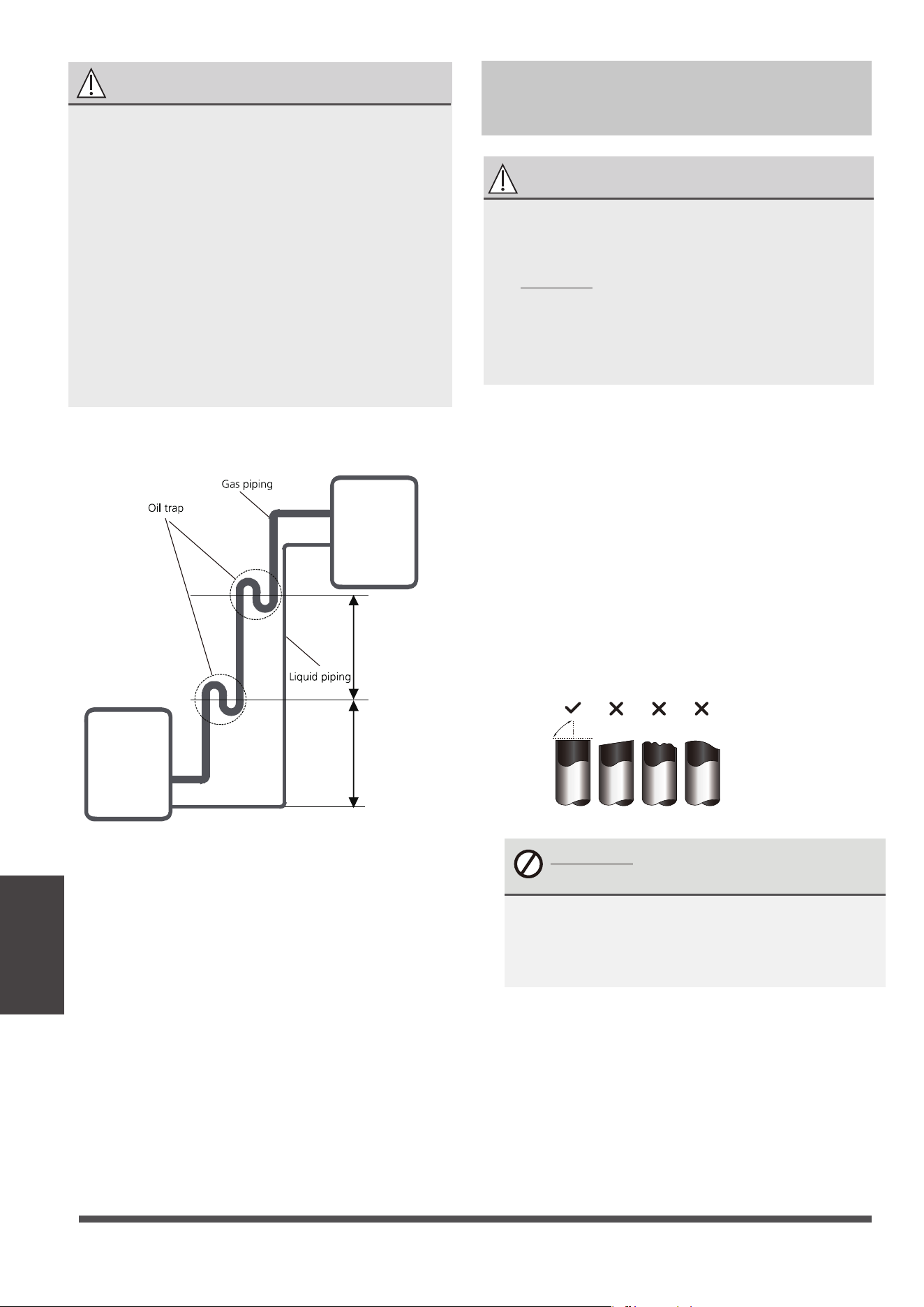
Step 2: Remove burrs.
Burrs can aect the air-tight seal of refrigerant
piping connection. They must be completely
removed.
1.
Hold the pipe at a downward angle to
prevent burrs from falling into the pipe.
Step 1: Cut pipes
When preparing refrigerant pipes, take extra
care to cut and flare them properly. This will
ensure efficient operation and minimize the
need for future maintenance.
1. Measure the distance between the indoor
and outdoor units.
CAUTION
• The branching pipe must be installed
horizontally. An angle of more than 10° may
cause malfunction.
• DO NOT install the connecting pipe until
both indoor and outdoor units have been
installed.
• Insulate both the gas and liquid piping to
prevent water leakage.
Connection Instructions –
Refrigerant Piping
Oil traps
If oil flows back into the outdoor unit’s
compressor, this might cause liquid
compression or deterioration of oil
return. Oil traps in the rising gas piping
can prevent this.
Page 31
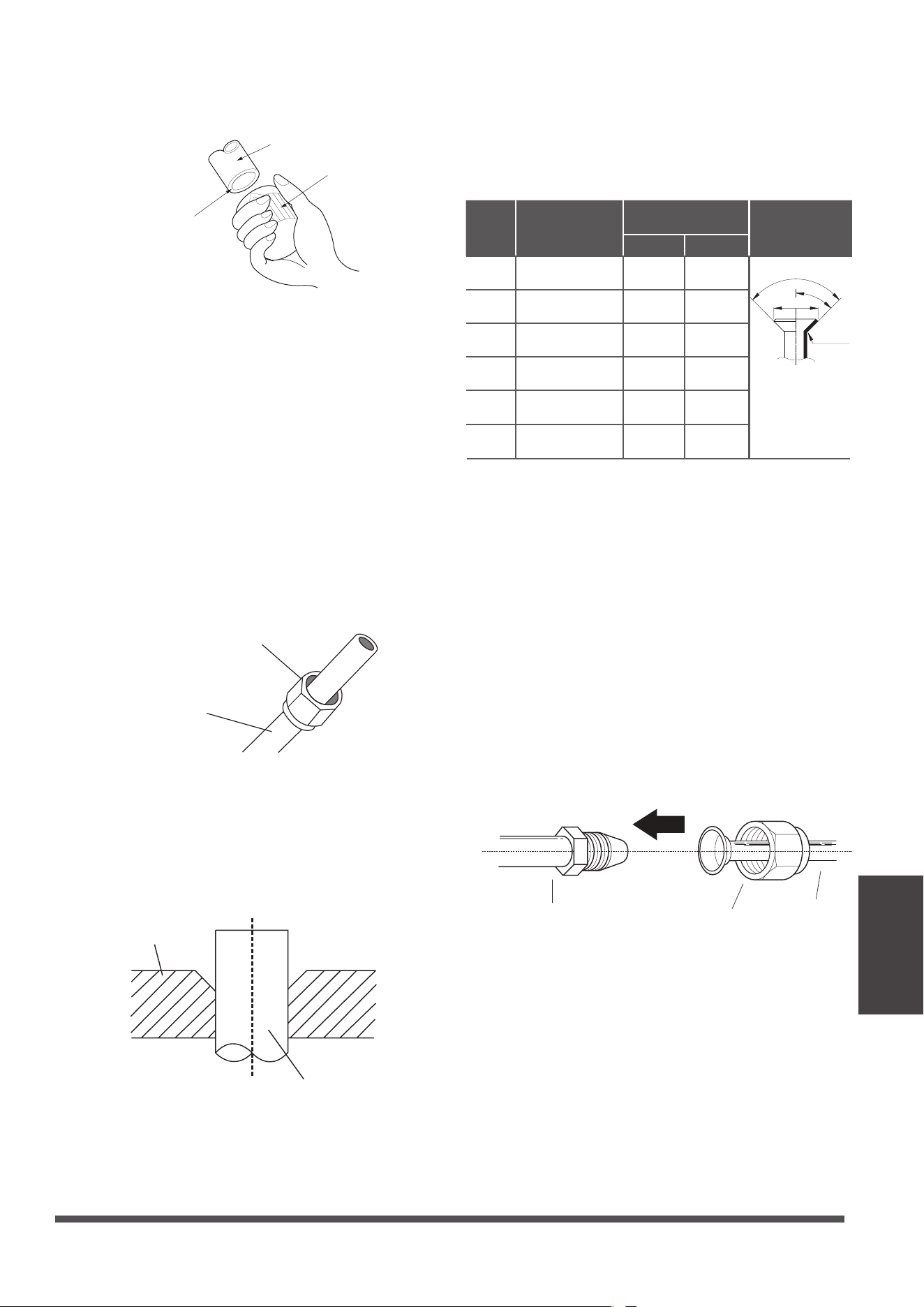
Step 3: Flare pipe ends
Proper aring is essential to achieve an airtight
seal.
1.
After removing burrs from cut pipe, seal
the ends with PVC tape to prevent foreign
materials from entering the pipe.
2.
Sheath the pipe with insulating material.
3.
Place are nuts on both ends of pipe.
Make sure they are facing in the right
direction, because you can’t put them on
or change their direction after flaring.
Flare nut
Copper pipe
4.
Remove PVC tape from ends of pipe when
ready to perform aring work.
5.
Clamp are form on the end of the pipe.
The end of the pipe must extend beyond
the are form.
Flare form
Pipe
2.
Using a reamer or deburring tool, remove
all burrs from the cut section of the pipe.
Pipe
Reamer
Point down
Refrigerant piping
Connection
6.
Place aring tool onto the form.
7.
Turn the handle of the aring tool
clockwise until the pipe is fully ared. Flare
the pipe in accordance with the dimensions.
PIPING EXTENSION BEYOND FLARE FORM
8. Remove the aring tool and are form,
then inspect the end of the pipe for cracks
and even aring.
Step 4: Connect pipes
Connect the copper pipes to the indoor unit rst,
then connect it to the outdoor unit. You should
rst connect the low-pressure pipe, then the high-
pressure pipe.
1.
When connecting the are nuts, apply a
thin coat of refrigeration oil to the ared
ends of the pipes.
2.
Align the center of the two pipes that you
will connect.
Indoor unit tubing
Flare nut
Pipe
3. Tighten the flare nut as tightly as
possible by hand.
4. Using a spanner, grip the nut on the
unit tubing.
Pipe
gauge
Tightening
torque
Flare dimension
(A) (Unit: Inch/mm)
Flare shape
Min. Max.
Ø 6.35
R0.4~0.8
45
°
±
2
90
°
±
4
A
Ø 9.52
Ø 12.7
Ø 16
Ø 19
Ø 22
65-67 N.m
(663-683 kgf.cm)
0.91/23.2 0.93/23.7
75-85N.m
(765-867 kgf.cm)
1.04/26.4 1.06/26.9
18-20 N.m
(183-204 kgf.cm)
0.33/8.4 0.34/8.7
25-26 N.m
(255-265 kgf.cm)
0.52/13.2 0.53/13.5
35-36 N.m
(357-367 kgf.cm)
0.64/16.2 0.65/16.5
45-47 N.m
(459-480 kgf.cm)
0.76/19.2 0.78/19.7
Page 32
Refrigerant piping
Connection
5. While rmly gripping the nut, use a torque
wrench to tighten the are nut according
to the torque values in above table.
NOTE: Use both a spanner and a torque wrench
when connecting or disconnecting pipes to/from
the unit.
CAUTION
•
Ensure to wrap insulation around the piping.
Direct contact with the bare piping may
result in burns or frostbite.
•
Make sure the pipe is properly connected.
Over tightening may damage the bell mouth
and under tightening may lead to leakage.
NOTE ON MINIMUM BEND RADIUS
Carefully bend the tubing in the middle
according to the diagram below. DO NOT bend
the tubing more than 90° or more than 3 times.
Bend the pipe with thumb
min-radius 3.9” (10cm)
6.
After connecting the copper pipes to the indoor
unit, wrap the power cable, signal cable and the
piping together with binding tape.
NOTE: DO NOT intertwine signal cable with
other wires. While bundling these items
together, do not intertwine or cross the signal
cable with any other wiring.
7. Thread this pipeline through the wall and
connect it to the outdoor unit.
8. Insulate all the piping, including the valves of
the outdoor unit.
9. Open the stop valves of the outdoor unit to
start the ow of the refrigerant between the
indoor and outdoor unit.
CAUTION
Check to make sure there is no refrigerant leak
after completing the installation work. If there is
a refrigerant leak, ventilate the area immediately
and evacuate the system (refer to the Air
Evacuation section of this manual).
Wiring
Page 33
BEFORE PERFORMING ANY
ELECTRICAL WORK, READ THESE
REGULATIONS
1. All wiring must comply with local and national
electrical codes, regulations and must be
installed by a licensed electrician.
2. All electrical connections must be made
according to the Electrical Connection Diagram
located on the panels of the indoor and outdoor
units.
3. If there is a serious safety issue with the power
supply, stop work immediately. Explain your
reasoning to the client, and refuse to install the
unit until the safety issue is properly resolved.
4. Power voltage should be within 90-110% of
rated voltage. Insucient power supply can
cause malfunction, electrical shock, or re.
5. If connecting power to xed wiring, a
surgeprotector and main power switch should
be installed.
6.
If connecting power to xed wiring, a switch
or cir
cuit breaker that disconnects all poles and
has a contact separation of at least 1/8in (3mm)
must be incorporated in the xed wiring. The
qualied technician must use an approved
circuit breaker or switch.
13.
Make sure that you do not cross your
electrical wiring with your signal wiring.
This may cause distortion and
interference.
14.
The unit must be connected to the
main outlet. Normally, the power supply
must have a impedance of 32 ohms.
15.
No other equipment should be
connected to the same power circuit.
16.
Connect the outdoor wires before
connecting the indoor wires.
7. Only connect the unit to an individual branch
circuit outlet. Do not connect another
appliance to that outlet.
8. Make sure to properly ground the air conditioner.
9.
10.
11.
12.
Every wire must be rmly connected. Loose
wiring can cause the terminal to overheat,
resulting in product malfunction and possible re.
Do not let wires touch or rest against refrigerant
tubing, the compressor, or any moving parts
within the unit.
If the unit has an auxiliary electric heater, it must
be installed at least 40in (1 meter) away from any
combustible materials.
To avoid getting an electric shock, never touch
the electrical components soon after the power
supply has been turned o. After turning o
the power, always wait 10 minutes or more
before you touch the electrical components.
WARNING
BEFORE PERFORMING ANY
ELECTRICAL OR WIRING WORK,
TURN OFF THE MAIN POWER TO
THE SYSTEM.
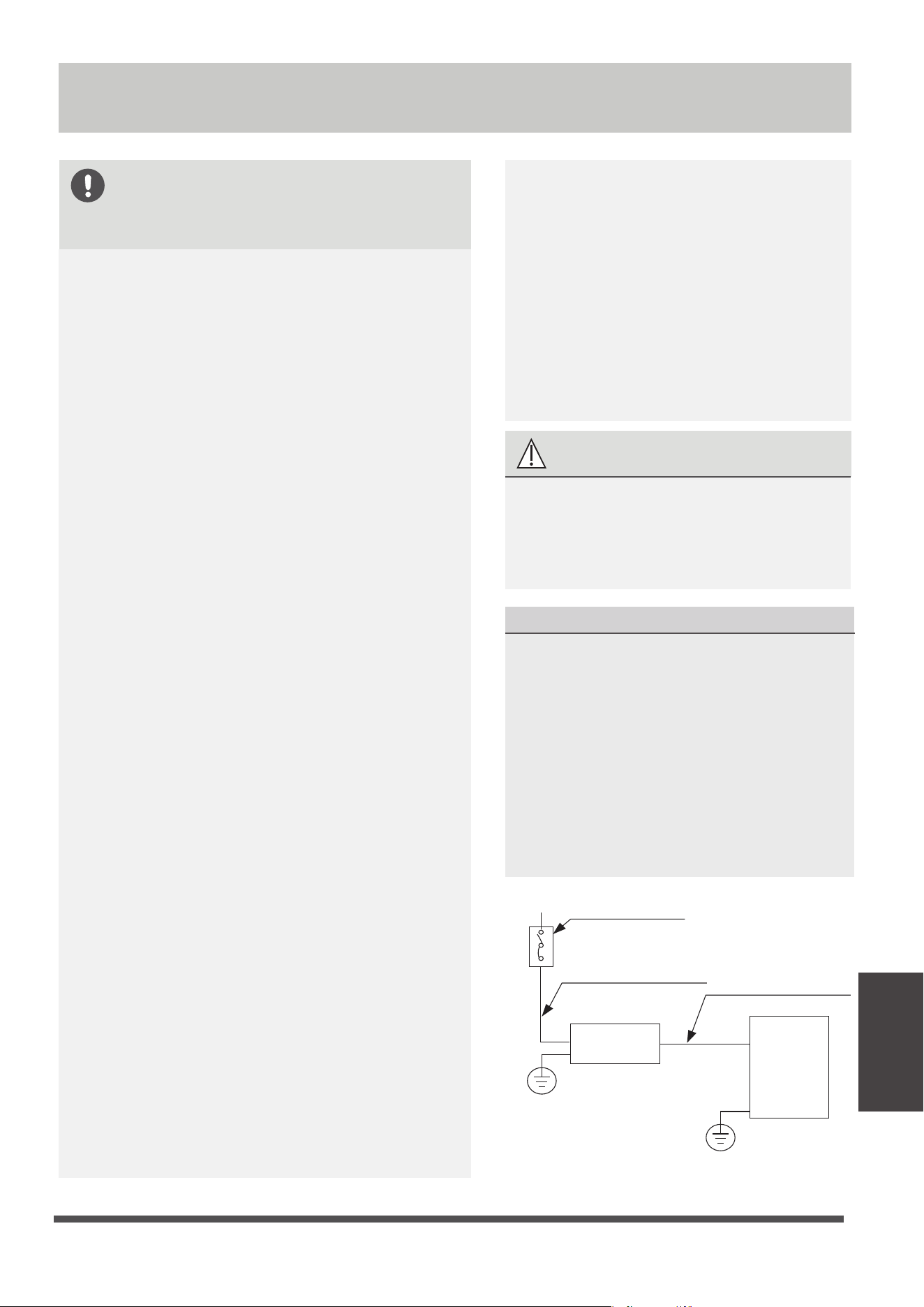
Wiring
Indoor unit
Outdoor unit
Air switch
(purchased seperately)
(purchased seperately)
Outdoor unit power wires
Indoor & Outdoor
connective wires
(A)
NOTE ON AIR SWITCH
When the maximum current of the air
conditioner is more than 16A, an air switch or
leakage protection switch with protective
device shall be used(purchased seperately) .
When the maximum current of the air
conditioner is less than 16A, the power cord
of air conditioner shall be equipped with
plug (purchased seperately) .
In North America,the applicance should be
wired according to NEC and CEC requirements.
Wiring
Page 34
Outdoor Unit Wiring
WARNING
Before performing any electrical or wiring
work, turn o the main power to the
system.
1. Prepare the cable for connection
a. You must rst choose the right cable
size. Be sure to use H07RN-F cables.
Minimum Cross-Sectional Area of
Power and Signal Cables (For reference)
Rated Current of
Appliance (A)
Nominal Cross-Sectional
Area ft² (mm²)
> 3 and ≤ 6
8.07/0.75
> 6 and ≤ 10
1.07/1
> 10 and ≤ 16
1.6/1.5
> 16 and ≤ 25
2.69/2.5
> 25 and ≤ 32
4.3/4
> 32 and ≤ 40
6.4/6
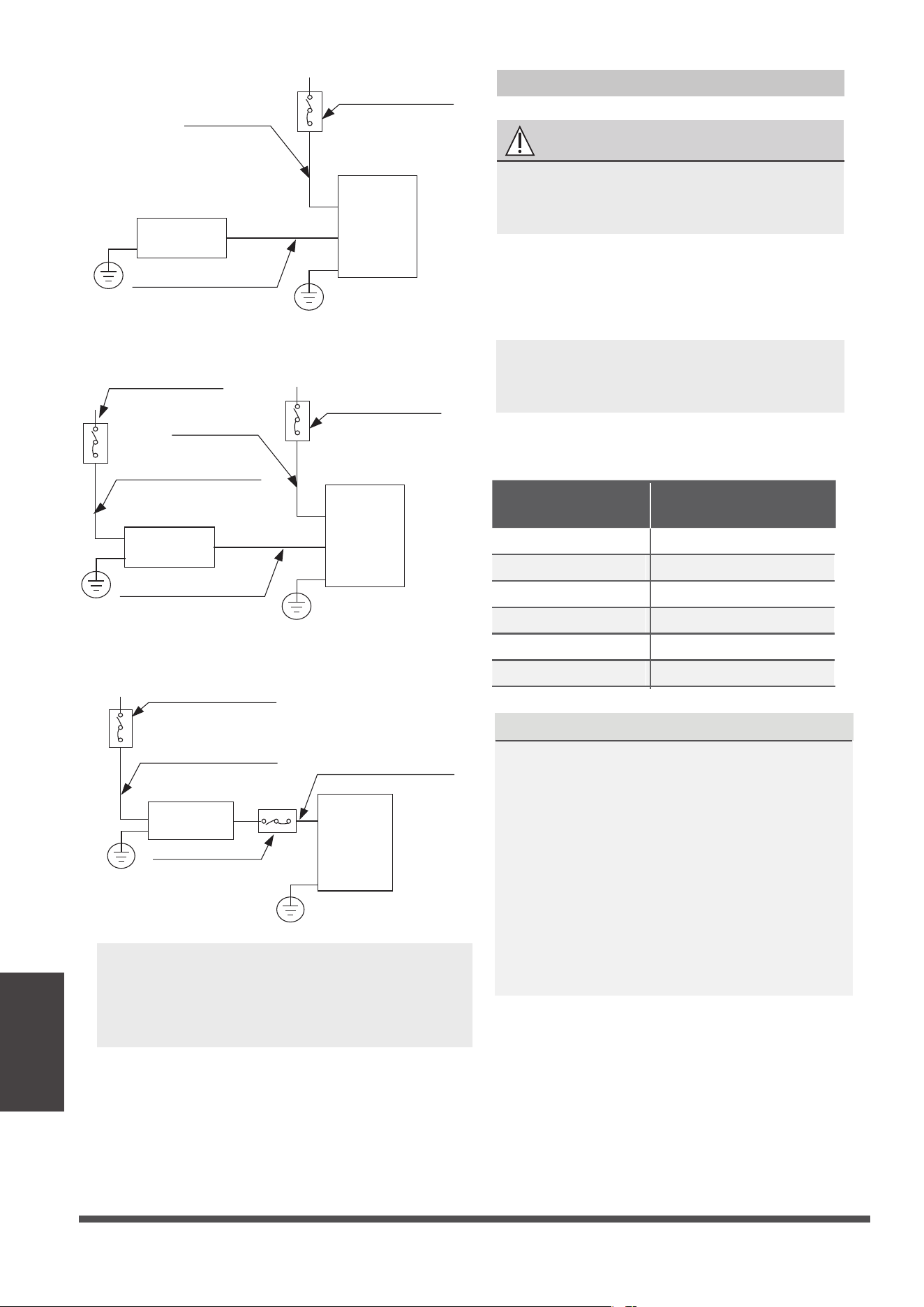
Indoor unit
Outdoor unit
Air switch
(purchased seperately)
(purchased seperately)
Indoor unit power wires
Indoor & Outdoor
connective wires
(B)
Indoor unit
Outdoor unit
Air switch
(purchased seperately)
Air switch
(purchased seperately)
(purchased seperately)
Indoor unit power wires
Indoor & Outdoor
connective wires
Outdoor unit power wires
(C)
NOTE: The cographs are for explanation
purpose only. Your machine may be
slightly dierent. The actual shape shall
prevail.
Indoor unit
Outdoor unit
Air switch
Air switch
(purchased seperately)
(Only for the North American)
(purchased seperately)
(purchased seperately)
Outdoor unit power wires
Indoor & Outdoor
connective wires
(D)
NOTE: In North America, choose the
cable type according to the local
electrical codes and regulations.
CHOOSE THE RIGHT CABLE SIZE
The size of the power supply cable, signal
cable, fuse, and switch needed is determined
by the maximum current of the unit. The
maximum current is indicated on the nameplate
located on the side panel of the unit. Refer to
this nameplate to choose the right cable, fuse,
or switch.
NOTE: In North America, please choose the
right cable size according to the Minimum
Circuit Ampacity indicated on the nameplate
of the unit.
Using a wire crimper, crimp u-lugs on the
ends.
b. Using wire strippers, strip the rubber
jacketfrom both ends of the signal cable to
reveal approximately 5.9” (15cm) of wire.
c. Strip the insulation from the ends.
d.
NOTE: When connecting the wires, strictly
follow the wiring diagram found inside the
electrical box cover.
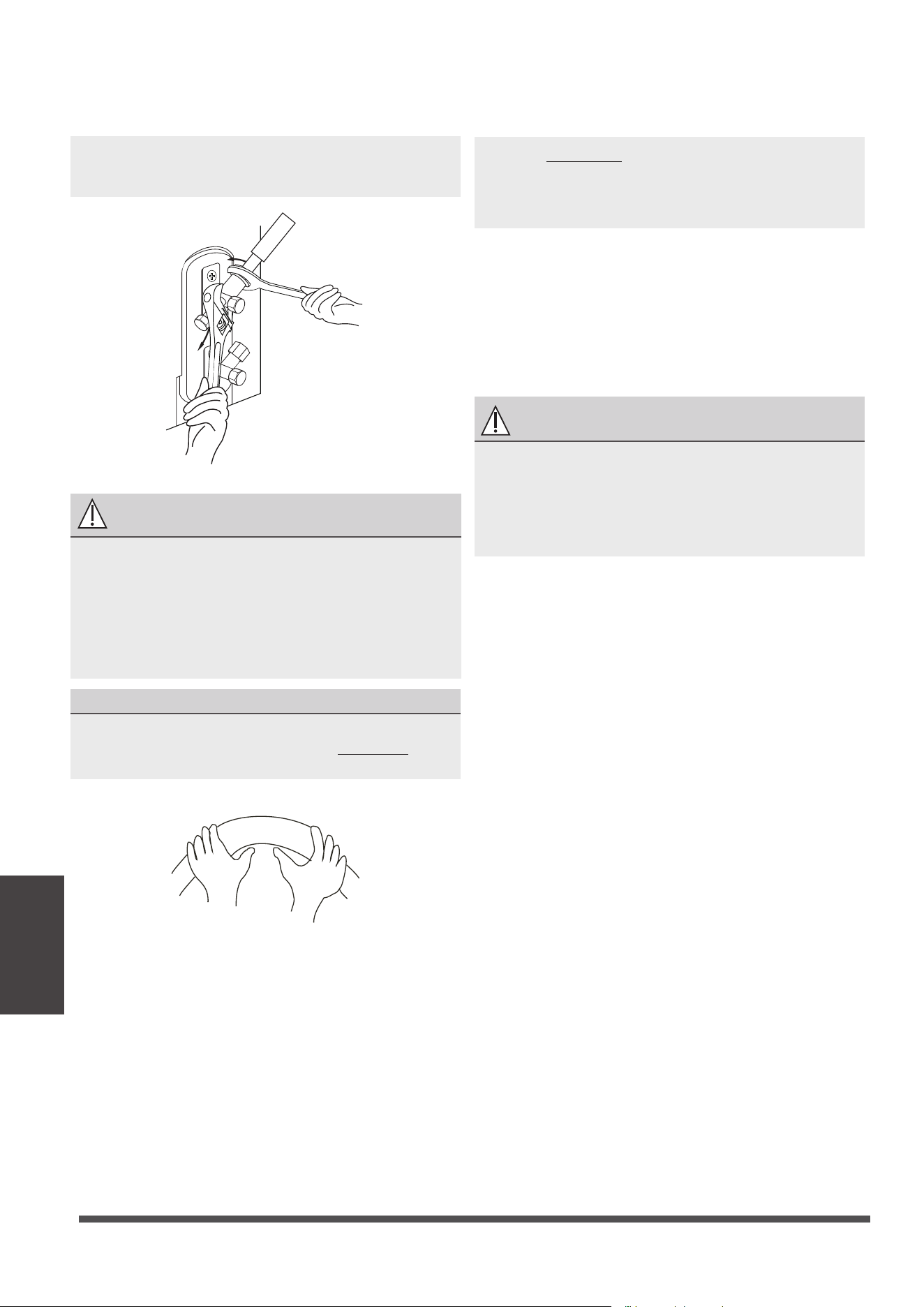
2. Remove the electric cover of the outdoor unit.
If there is no cover on the outdoor unit, take
o the bolts from the maintenance board
and remove the protection board.
3. Connect the u-lugs to the terminals
Match the wire colors/labels with the labels
on the terminal block. Firmly screw the u-lug
of each wire to its corresponding terminal.
4. Clamp down the cable with the cable clamp.
5. Insulate unused wires with electrical tape.
Keep them away from any electrical or metal
parts.
6. Reinstall the cover of the electric control box.
Cover
Screw
Magnetic ring
(if supplied and packed with the
accessories)
1 2 3
Pass the belt through
the hole of the Magnetic
ring to fix it on the cable
Indoor Unit Wiring
1. Prepare the cable for connection
a. Using wire strippers, strip the rubber jacket
from both ends of the signal cable to reveal
about 5.9”
(15cm) of the wire.
b.
Strip the insulation from the ends of the wires.
c. Using a wire crimper, crimp the u-lugs to
the
ends of the wires.
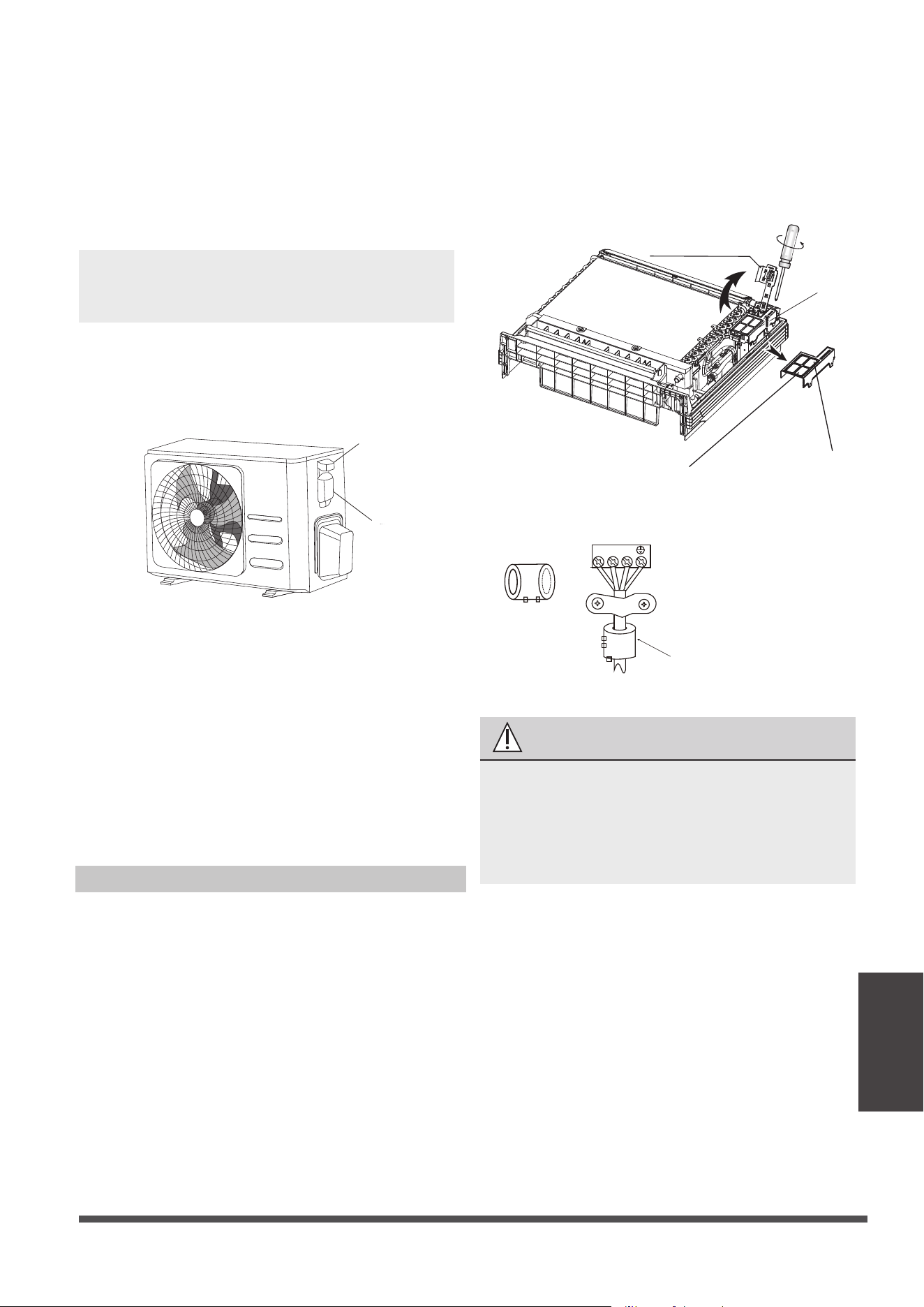
2. Rotate the sensor device’s installation bearer to
the other side. Then remove the cover of the
electrical box. (Also, remove the electrical box
also if its capacity is 18000btu/h and has
networking functionality.)
3.
Connect the u-lugs to the terminals.
Match the wire colors/labels with the labels on
the terminal block, Firmly screw the u-lug of
each wire to its corresponding terminal. Refer
to the Serial Number and Wiring Diagram
located on the cover of the electric control box.
Connective wiring
diagramWiring diagram
Control box
Installation bearer
of sensor device
CAUTION
• While connecting the wires, please
strictly follow the wiring diagram.
•
The refrigerant circuit can become very hot.
Keep the interconnection cable away from
the copper tube.
4.
Clamp down cable with the designated cable
clamp to secure it in place. The cable should
not be loose, and should not pull on the u-lugs.
5. Reinstall the electric box cover and the front
panel of the indoor unit.
Page 35
Wiring

Power Specifications(Not applicable for North America)
MODEL
(Btu/h)
POWER
PHASE
FREQUENCY AND VOLT
CIRCUIT BREAKER/FUSE(A)
INDOOR UNIT POWER WIRING
(mm²)
OUTDOOR UNIT POWER WIRING
GROUND WIRING
STRONG ELECTRIC SIGNAL
WEAK ELECTRIC SIGNAL
INDOOR/OUDOOR
CONNECTING
WIRING (mm²)
<16K
1 Phase
220-240V~, 50Hz/60Hz
20/16
——
3x1.5
——
4x1.0
1.5
16K~18K
1 Phase
220-240V~, 50Hz/60Hz
20/16
3x1.0
3x2.5
3x0.2
2.5
——
Page 36
Wiring
Preparations and Precautions
Air and foreign matter in the refrigerant circuit can
cause abnormal rises in pressure, which can damage
the air conditioner, reduce its efficiency, and cause
injury. Use a vacuum pump and manifold gauge to
evacuate the refrigerant circuit, removing any
non-condensable gas and moisture from the system.
Evacuation should be performed upon initial
installation and when unit is relocated.
BEFORE PERFORMING EVACUATION
Check to make sure the connective pipes
between the indoor and outdoor units
are connected properly .
Check to make sure all wiring is connected
properly.
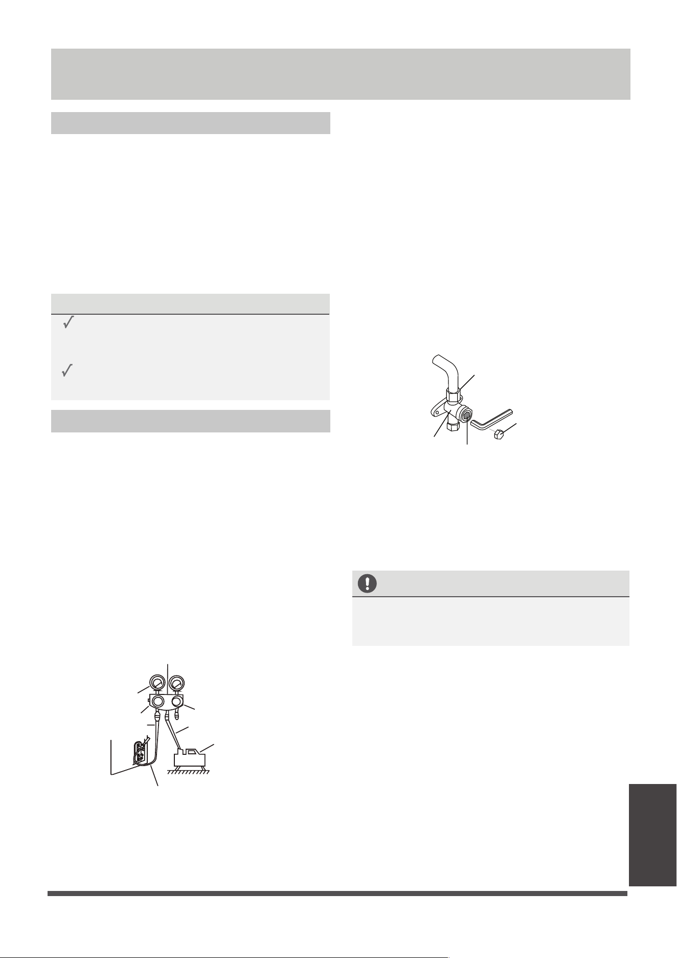
Evacuation Instructions
Manifold Gauge
Compound
gauge
-76cmHg
Low pressure
valve
High pressure
valve
Pressure hose /
Charge hose
Charge hose
V
acuum
pump
Pressure gauge
Low pressure valve
1.
Connect the charge hose of the manifold
gauge to service port on the outdoor unit’s
low pressure valve.
Connect another charge hose from the
manifold gauge to the vacuum pump.
Open the Low Pressure side of the manifold
gauge. Keep the High Pressure side closed.
Turn on the vacuum pump to evacuate the
system.
Run the vacuum for at least 15 minutes, or
until the Compound Meter reads -76cmHG
(-10
5
Pa).
2.
3.
4.
5.
6.
Close the Low Pressure side of the manifold
gauge, and turn o the vacuum pump.
7.
Wait for 5 minutes, then check that there
has been no change in system pressure.
8.
If there is a change in system pressure, refer
to Gas Leak Check section for information
on how to check for leaks. If there is no
change in system pressure, unscrew the cap
from the packed valve (high pressure valve).
9.
Insert hexagonal wrench into the packed valve
(high pressure valve) and open the valve by
turning the wrench in a 1/4 counterclockwise
turn. Listen for gas to exit the system, then
close the valve after 5 seconds.
10.
Watch the Pressure Gauge for one minute
to make sure that there is no change in
pressure. The Pressure Gauge should read
slightly higher than atmospheric pressure.
Flare nut
Cap
valve body
valve stem
11.
Remove the charge hose from the service port.
12.
Using hexagonal wrench, fully open both the
high pressure and low pressure valves.
13.
Tighten valve caps on all three valves (service
port, high pressure, low pressure) by hand.
You may tighten it further using a torque
wrench if needed.
OPEN VALVE STEMS GENTLY
When opening valve stems, turn the hexagonal
wrench until it hits against the stopper. Do not
try to force the valve to open further.
Air Evacuation
Page 37
Air Evacuation
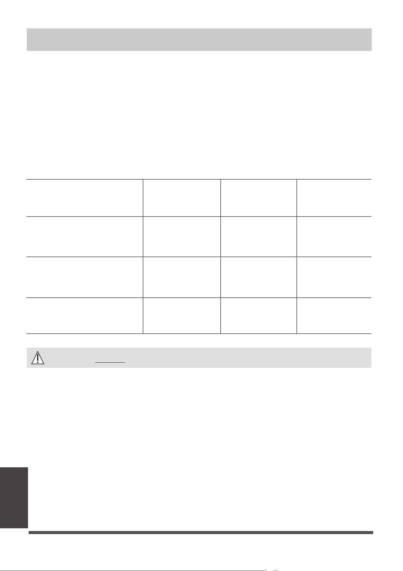
Note on Adding Refrigerant
Some systems require additional charging depending on pipe lengths. The standard pipe length varies
according to local regulations. For example, in North America, the standard pipe length is 25’ (7.5m).
In other areas, the standard pipe length is 16‘ (5m). The refrigerant should be charged from the service
port
on the outdoor unit’s low pressure valve.
The additional refrigerant to be charged can be
calculated using the following formula:
CAUTION
DO NOT mix refrigerant types.
Liquid Side Diameter
R32 :
(Total pipe length -
standard pipe
length)0.13oZ (x 12g)
/ft(m)
(Total pipe length -
standard pipe
length)0.26oZ (x24g)/
ft(m)
(Total pipe length -standard
pipe length)0.42oZ (x 40g)/
ft(m)
φ1/4”(6.35)
φ3/8”(9.52)
φ
1/2”(12.7)
(Total pipe length -
standard pipe
length)0.69oZ (x65g)/
ft(m)
R410A:
(orifice tube in the indoor unit):
(Total pipe length -
standard pipe length)
0.32oZ (x30g)/ft(m)
(Total pipe length -
standard pipe length)
0.69oZ (x65g)/ft(m)
(Total pipe length -
standard pipe
length)1.23oZ(x115g)/ft(m)
R410A:
(orifice tube in the outdoor unit):
(Total pipe length -
standard pipe length)
0.16oZ (x15g)/ft(m)
(Total pipe length -
standard pipe
length)x30g (x30g)/
ft(m)
Only for Australia models :
• This unit contains factory charged refrigerant covering 65ft/20m of refrigerant piping and
additional refrigerant charge on the installation site is not required for an installation with up to
20m refrigerant piping. When refrigerant piping exceeds 20m, additionally charge an amount
calculated from the pipe length and the above table for the portion in excess of 65ft/20m.
• If an existing pipe system is used, a required refrigerant charge volume will vary depending on
the liquid pipe size.
Formula to calculate the volume of additional refrigerant required:
Additional charge volume (kg) = { Main length (ft/m) – Factory charged volume 65ft/(20m) } ×
0.03(kg/m)
• Make sure to remove the additional refrigerant amount according to the nameplate rated
charge (under 16ft/5m refrigerant piping ) under market or government verification testing .
Page 38
Air Evacuation
Test Run
Before Test Run
A test run must be performed after the entire
system has been completely installed. Confirm
the following points before performing the test:
a) Indoor and outdoor units are properly
installed.
b) Piping and wiring are properly connected.
c)
No obstacles near the inlet and outlet of
the unit that might cause poor performance
or product malfunction.
d) Refrigeration system does not leak.
e) Drainage system is unimpeded and
draining to a safe location.
f) Heating insulation is properly installed.
g) Grounding wires are properly connected.
h) Length of the piping and additional
refrigerant stow capacity have been
recorded.
i) Power voltage is the correct voltage
for the air conditioner.
CAUTION
Failure to perform the test run may result in
unit damage, property damage, or personal
injury.
Test Run Instructions
1. Open both the liquid and gas stop valves.
2. Turn on the main power switch and allow the
unit to warm up.
3. Set the air conditioner to COOL mode.
4. For the Indoor Unit
a. Ensure the remote control and its buttons
work properly.
b. Ensure the louvers move properly and can
be changed using the remote control.
c. Double check to see if the room
temperature is being registered correctly.
d. Ensure the indicators on the remote
control and the display panel on the indoor
unit work properly.
e. Ensure the manual buttons on the indoor
unit works properly.
f. Check to see that the drainage system is
unimpeded and draining smoothly.
g. Ensure there is no vibration or abnormal
noise during operation.
5. For the Outdoor Unit
a. Check to see if the refrigeration system is
leaking.
b. Make sure there is no vibration or
abnormal noise during operation.
c. Ensure the wind, noise, and water
generated by the unit do not disturb your
neighbors or pose a safety hazard.
6. Drainage Test
a. Ensure the drainpipe flows smoothly. New
buildings should perform this test before
finishing the ceiling.
b. Remove the test cover. Add 2,000ml of
water to the tank through the attached
tube.
c. Turn on the main power switch and run
the air conditioner in COOL mode.
d. Listen to the sound of the drain pump to
see if it makes any unusual noises.
e. Check to see that the water is discharged.
It may take up to one minute before the
unit begins to drain depending on the
drainpipe.
f. Make sure that there are no leaks in any of
the piping.
g. Stop the air conditioner. Turn o the main
power switch and reinstall the test cover.
NOTE: If the unit malfunctions or does not
operate according to your expectations,
please refer to the Troubleshooting section
of the Owner’s Manual before calling
customer service.
Test Run
Page 39
LIMITED WARRANTY STATEMENT
PRODUCT REGISTRATION:
Model No.: ______________________________________________________________________________________________
Serial No.: _______________________________________________________ Date of Installation: ______________________
Owner Name: ____________________________________________________________________________________________
Address of Installation:_____________________________________________________________________________________
Installing Contractor: __________________________________________________________________________
____________
Address: ________________________________________________________________________________________
Phone No. / E-mail: _______________________________________________________________________________
Place Of Purchase:
________________________________________________________________________________________
Date of Purchase:
_______________________________________________________________________________
www.cooperandhunter.us
Visit our website for:
• Product Information
• Warranty Registration
• Installation Manual
• User Guides and more
www.cooperandhunter.us
Visit our YouTube Channel for:
• Instructional Videos
• Tutorials and How Tos
• Product Introductions
• Advertisement and more
www.youtube.com/
cooperandhunterusa
The warranty should be registered on our website www.cooperandhunter.us or by submitting the card below within
60 days of installation. The warranty is only valid when unit is installed by a licensed HVAC technician and registered
within 60 days of installation date. If you decide to submit card, send by e-mail to [email protected]
License Number: __________________________________________________________________________
____________
AIR HANDLER
For warranty service or repair:
Contact your installing contractor
C&H distributor (hereinafter “Company”) warrants this product against failure due to defect in materials or workmanship
under normal use and maintenance as follows. All warranty periods begin on the date of original installation.
if the date cannot be veried, the warranty period beginsone hundred twenty (120) days from date of manufacture.
Damage resulting from failure to use, install or maintain the product in a manner consistent with our/manufacturer’s
recommendations shall render the warranty void. Cooper&Hunter, at its option, may request a report from a qualied
technician prior to honoring a warranty claim. if a part fails due to defect duringthe applicable warranty period.
Company will provide a new or remanufactured part, at Company’s option, to replace the failed defective part at no
charge for the part. This limited warranty is subject to all provisions, conditions, limitations and exclusions listed below.
• A limited warranty covers 7 yrs compressor for commercial residential applications
• Limited warranty covers 5 year for Cooper&Hunter parts
•
under applicable local and state law in accordance with all applicable building codes and permits; C&H installation and
operation instructions and good trade practices.
• Warranty applies only to products remaining in their original installation location.
• Defective parts must be returned to the distributor through a registered servicing dealer for credit.
LIMITATIONS OF WARRANTIES: ALL IMPLIED WARRANTIES AND/OR CONDITIONS (INCLUDING IMPLIED WARRANTIES OR
CONDITIONS OF MERCHANTABILITY AND FITNESS FOR A PARTICULAR USE OR PURPOSE) ARE LIMITED TO THE DURATION
OF THIS LIMITED WARRANTY. SOME STATES OR PROVINCES DO NOT ALLOW LIMITATIONS ON HOW LONG AN IMPLIED
WARRANTY OR CONDITION LASTS, SO THE ABOVE MAY NOT APPLY TO YOU. THE EXPRESS WARRANTIES MADE IN THIS
WARRANTY ARE EXCLUSIVE AND MAY NOT BE ALTERED, ENLARGED, OR CHANGED BY ANY DISTRIBUTOR, DEALER, OR
OTHER PERSON, WHATSOEVER.
THIS WARRANTY DOES NOT COVER:
1. Labor or other costs incurred for diagnosing, repairing, removing, installing, shipping, servicing, or handling of
defective parts, replacement parts, or new units.
2. Product cleaning required prior to warranty service and repair.
3.
4. Failure, damage, or repairs due to faulty installation, misapplication, abuse, improper servicing, unauthorized
alteration,
or improper operation.
5. Failure
to start due to voltage conditions, blown fuses, open circuit breakers, or damages due to the inadequacy or
interruption of electrical service.
6.
conditions beyond the control of Company.
7. Failure or damage of coils or piping due to corrosion on installations within one (1) mile of a sea coast or a corrosive
body.
8. Parts not supplied or designated by Company, or damages resulting from their use.
9. Products installed outside the continental USA and Canada.
10. Electricity or fuel costs, or increases in electricity or fuel costs for any reason whatsoever, including additional or
unusual use of supplemental electric heat.
11.
12. Shipping damage or damage as a result of transporting the unit.
13. Accessories such as condensate pumps, line sets, and so forth.
14. Any special, indirect, or consequential property or commercial damage of any nature whatsoever. Some states or
provinces do not allow the exclusion of incidental or consequential damages, so the above limitation may not apply to
you.
to province.
Consult with the sales agency or manufacturer for details.
• Warranty applies only to air handler units which are installed and used exclusively with Cooper&Hunter equipment
and accessories.
Design and specications are subject to change without notice for product improvement.
Normal maintenance as outlined in the installation and servicing instructions or user’s manual, including lter
cleaning and/or replacement and lubrication
Failure or damage due to oods, winds, res, lightning, accidents, corrosive enviorments (rust, etc.) or other
Any cost to replace, rell, or dispose of refrigerant, including the cost of refridgerant
Limited warranty applies only to systems that are properly installed by a state certied or licensed HVAC contractor