
Questions? Call GE Appliances at 1.800.GE.CARES (1.800.432.2737) or visit
GEAppliances.com.
FOR YOUR SAFETY:
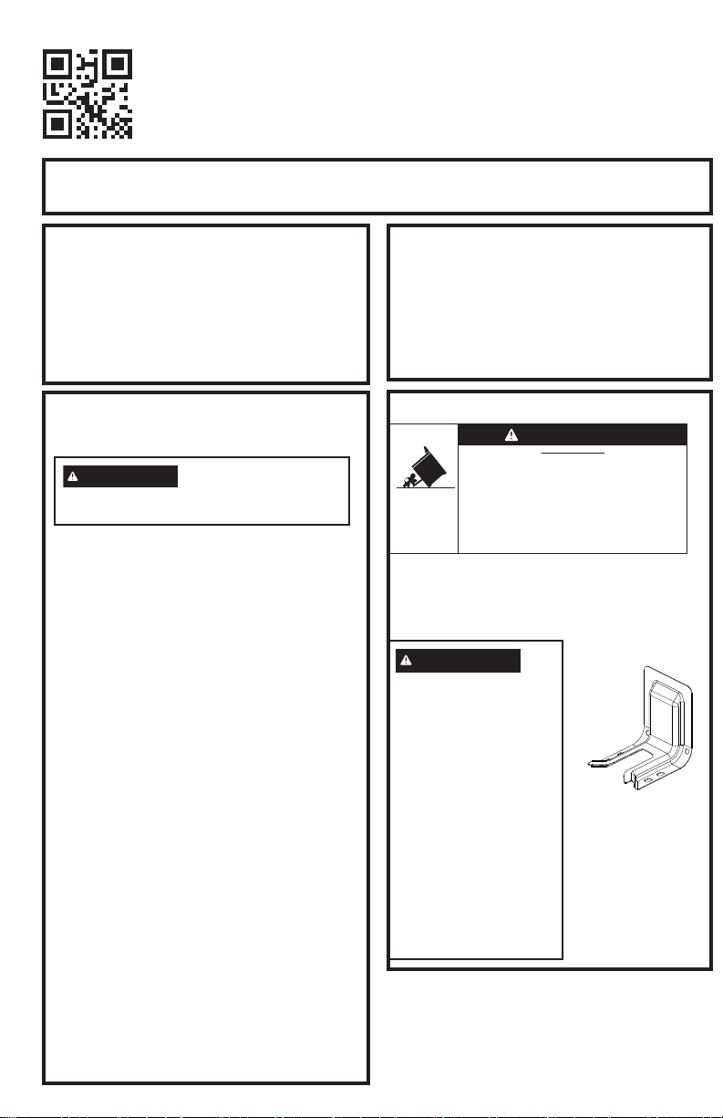
If you did not receive an anti-tip bracket with
your purchase, call 1.800.626.8774 to receive
one at no cost. For installation instructions of the
bracket, visit: GEAppliances.com.
Remove any
currently used
anti-tip bracket
and install with
the provided
anti-tip bracket
and screws.
WARNING
Before beginning the
installation, switch
power off at service
panel and lock the
service disconnecting
means to prevent power
from being switched on
accidentally. When the
service disconnecting
means cannot be
locked, securely fasten
a prominent warning
device, such as a tag,
to the service panel.
Anti-Tip
Bracket
and
Screws
Included
• A child or adult can tip the range and be killed.
• Install the anti-tip bracket provided with the unit
to the wall or floor.
• Engage the range to the anti-tip bracket by sliding the
range back such that the foot is engaged.
• Re-engage the anti-tip bracket if the range is moved.
• Failure to do so can result in death or serious burns
to children or adults.
Tip-Over Hazard
WARNING
PROPER DISPOSAL OF YOUR
APPLIANCE
Dispose of or recycle your appliance
in accordance with Federal and Local
Regulations. Contact your local authorities for
the environmentally safe disposal or recycling
of your appliance.
Installation Instructions
Gas Range
IN THE COMMONWEALTH OF
MASSACHUSETTS
• This product must be installed by a
licensed plumber or gas fitter.
• When using ball type gas shut-off valves,
they shall be the T-handle type.
• A flexible gas connector, when used, must
not exceed 5 feet.
BEFORE YOU BEGIN
Read these instructions completely and
carefully.
• IMPORTANT – Save these instructions
for local inspector’s use.
• IMPORTANT – Observe all governing
codes and ordinances.
• Note to Installer - Be sure to leave these
instructions with the Consumer.
• Note to Consumer – Keep these
instructions for future reference.
• Note to Servicer – The electrical diagram
is in an envelope attached to the left side
panel, when the drawer is removed.
• Proper installation is the responsibility of
installer.
• Product failure due to improper installation is
not covered under the Warranty.
• IMPORTANT — Remove all packing
material and literature from oven before
connecting gas and electrical supply to
range.
• IMPORTANT — To avoid damage
to your cabinets, check with your builder
or cabinet supplier to make sure that the
materials used will not discolor, delaminate
or sustain other damage. This oven has
been designed in accordance with the
requirements of UL and CSA International
and complies with the maximum allowable
wood cabinet temperatures of 194°F (90°C).
•
Skill level – Installation of this appliance
requires advanced mechanical skills and
advanced electrical skills.
WARNING
Remove existing anti-tip
bracket from install space, if present.
WARNING
Fire or Explosion
Hazard
If the information in this manual is not
followed exactly, a fire or explosion may
result causing property damage, personal
injury or death.
Installation must be performed by a
qualified installer.
Installation of this range must conform
with local codes, or in the absence of local
codes, with the National Fuel Gas Code,
ANSI Z223.1/ NFPA.54, latest edition. In
Canada, installation must conform with
the current Natural Gas Installation Code,
CAN/CGA-B149.1 or the current Propane
Installation Code, CAN/CGA-B149.2,
and with local codes where applicable.
This range has been design-certified
by CSA International according to ANSI
Z21.1, latest edition and Canadian Gas
Association according to CAN/CGA-1.1
latest edition.
When installing a gas appliance the use
of old flexible connectors can cause gas
leaks and personal injury. Always use a
NEW flexible connector.
Leak testing of the appliance shall be
conducted according to the manufacturer
instructions.
The range must be electrically grounded
in accordance with local codes or, in the
absence of local codes, in accordance with
the National Electrical Code (ANSI/NFPA
70, latest edition). In Canada, electrical
grounding must be in accordance with the
current CSA C22.1 Canadian Electrical
Code Part 1 and/or local codes. See
Electrical Connections.
Do not install this product with an air
curtain hood or other range hood that
operates by blowing air down on the
cooktop. This airflow may interfere with
operation of the gas burners resulting in
fire or explosion hazard.
MATERIALS YOU MAY NEED
Ŷ*DVOLQHVKXWRIIYDOYH
Ŷ3LSHMRLQWVHDODQWRU8/DSSURYHGSLSH
thread tape with Teflon* that resists action
of natural and propane gases
Ŷ)OH[LEOHPHWDODSSOLDQFHFRQQHFWRU´
I.D.). A 5-foot length is recommended for
ease of installation but other lengths are
acceptable. Never use an old connector
when installing a new range.
Ŷ)ODUHXQLRQDGDSWHUIRUFRQQHFWLRQWRJDV
VXSSO\OLQH´RU´137[´,'
Ŷ)ODUHXQLRQDGDSWHUIRUFRQQHFWLRQWR
SUHVVXUHUHJXODWRURQUDQJH´137[
´,'
Ŷ/LTXLGOHDNGHWHFWRURUVRDS\ZDWHU
*Teflon: Registered trademark of DuPont
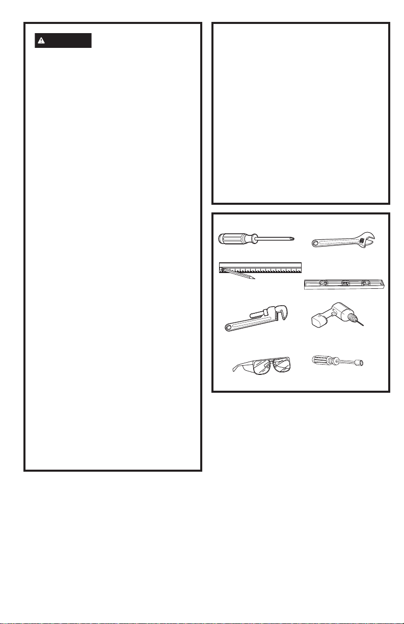
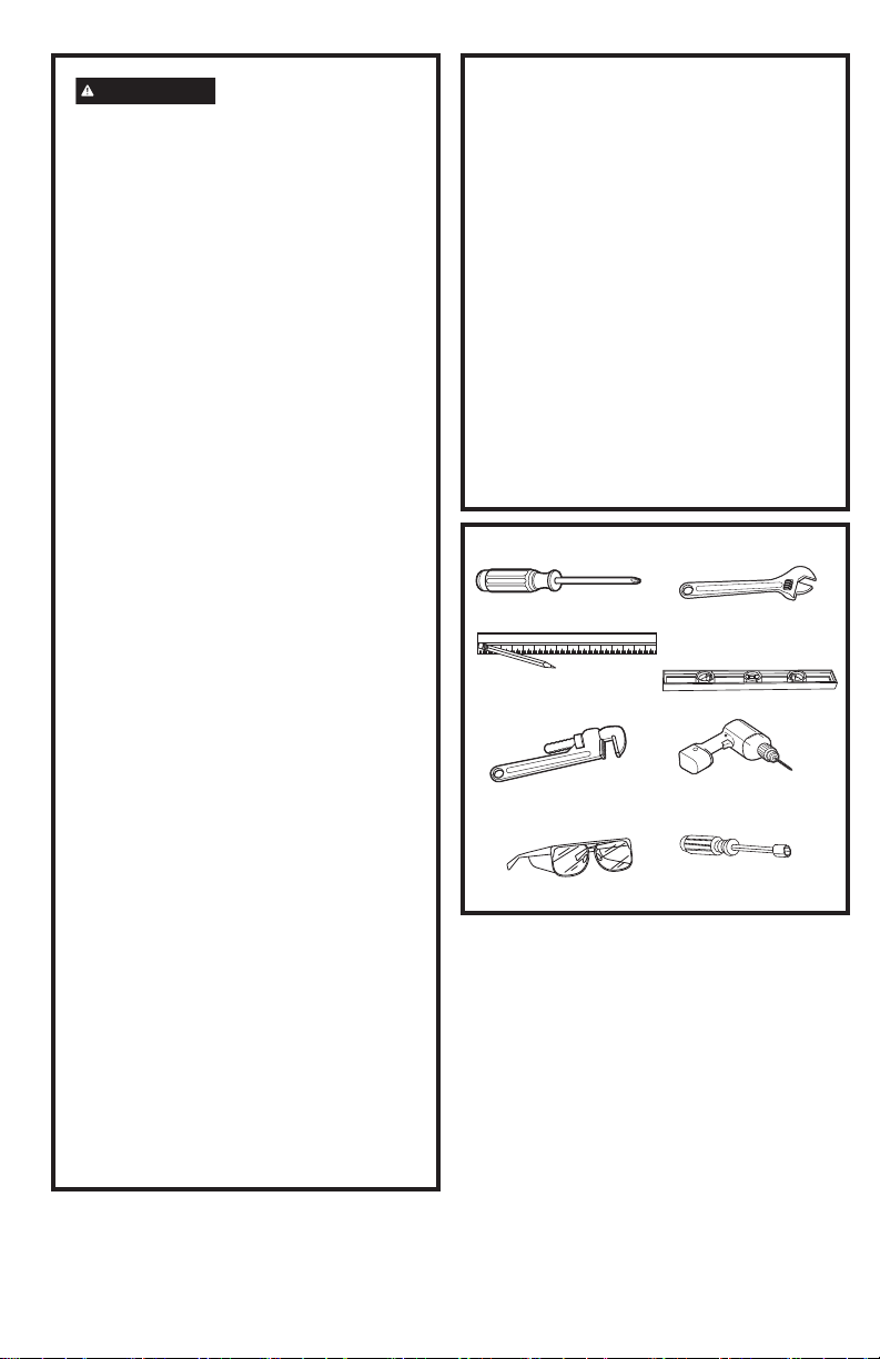
TOOLS YOU WILL NEED
Level
Phillips Screwdriver
Pencil and Ruler
Drill
Open-end or
Adjustable Wrench
Pipe Wrenches (2)
(one for backup)
Safety Glasses
´1XW'ULYHU
Questions? Call GE Appliances at 1.800.GE.CARES (1.800.432.2737) or visit
GEAppliances.com.
FOR YOUR SAFETY:
If you did not receive an anti-tip bracket with
your purchase, call 1.800.626.8774 to receive
one at no cost. For installation instructions of the
bracket, visit: GEAppliances.com.
Remove any
currently used
anti-tip bracket
and install with
the provided
anti-tip bracket
and screws.
WARNING
Before beginning the
installation, switch
power off at service
panel and lock the
service disconnecting
means to prevent power
from being switched on
accidentally. When the
service disconnecting
means cannot be
locked, securely fasten
a prominent warning
device, such as a tag,
to the service panel.
Anti-Tip
Bracket
and
Screws
Included
• A child or adult can tip the range and be killed.
• Install the anti-tip bracket provided with the unit
to the wall or floor.
• Engage the range to the anti-tip bracket by sliding the
range back such that the foot is engaged.
• Re-engage the anti-tip bracket if the range is moved.
• Failure to do so can result in death or serious burns
to children or adults.
Tip-Over Hazard
WARNING
PROPER DISPOSAL OF YOUR
APPLIANCE
Dispose of or recycle your appliance
in accordance with Federal and Local
Regulations. Contact your local authorities for
the environmentally safe disposal or recycling
of your appliance.
Installation Instructions
Gas Range
IN THE COMMONWEALTH OF
MASSACHUSETTS
• This product must be installed by a
licensed plumber or gas fitter.
• When using ball type gas shut-off valves,
they shall be the T-handle type.
• A flexible gas connector, when used, must
not exceed 5 feet.
BEFORE YOU BEGIN
Read these instructions completely and
carefully.
• IMPORTANT – Save these instructions
for local inspector’s use.
• IMPORTANT – Observe all governing
codes and ordinances.
• Note to Installer - Be sure to leave these
instructions with the Consumer.
• Note to Consumer – Keep these
instructions for future reference.
• Note to Servicer – The electrical diagram
is in an envelope attached to the left side
panel, when the drawer is removed.
• Proper installation is the responsibility of
installer.
• Product failure due to improper installation is
not covered under the Warranty.
• IMPORTANT — Remove all packing
material and literature from oven before
connecting gas and electrical supply to
range.
• IMPORTANT — To avoid damage
to your cabinets, check with your builder
or cabinet supplier to make sure that the
materials used will not discolor, delaminate
or sustain other damage. This oven has
been designed in accordance with the
requirements of UL and CSA International
and complies with the maximum allowable
wood cabinet temperatures of 194°F (90°C).
•
Skill level – Installation of this appliance
requires advanced mechanical skills and
advanced electrical skills.
WARNING
Remove existing anti-tip
bracket from install space, if present.
WARNING
Fire or Explosion
Hazard
If the information in this manual is not
followed exactly, a fire or explosion may
result causing property damage, personal
injury or death.
Installation must be performed by a
qualified installer.
Installation of this range must conform
with local codes, or in the absence of local
codes, with the National Fuel Gas Code,
ANSI Z223.1/ NFPA.54, latest edition. In
Canada, installation must conform with
the current Natural Gas Installation Code,
CAN/CGA-B149.1 or the current Propane
Installation Code, CAN/CGA-B149.2,
and with local codes where applicable.
This range has been design-certified
by CSA International according to ANSI
Z21.1, latest edition and Canadian Gas
Association according to CAN/CGA-1.1
latest edition.
When installing a gas appliance the use
of old flexible connectors can cause gas
leaks and personal injury. Always use a
NEW flexible connector.
Leak testing of the appliance shall be
conducted according to the manufacturer
instructions.
The range must be electrically grounded
in accordance with local codes or, in the
absence of local codes, in accordance with
the National Electrical Code (ANSI/NFPA
70, latest edition). In Canada, electrical
grounding must be in accordance with the
current CSA C22.1 Canadian Electrical
Code Part 1 and/or local codes. See
Electrical Connections.
Do not install this product with an air
curtain hood or other range hood that
operates by blowing air down on the
cooktop. This airflow may interfere with
operation of the gas burners resulting in
fire or explosion hazard.
MATERIALS YOU MAY NEED
Ŷ*DVOLQHVKXWRIIYDOYH
Ŷ3LSHMRLQWVHDODQWRU8/DSSURYHGSLSH
thread tape with Teflon* that resists action
of natural and propane gases
Ŷ)OH[LEOHPHWDODSSOLDQFHFRQQHFWRU´
I.D.). A 5-foot length is recommended for
ease of installation but other lengths are
acceptable. Never use an old connector
when installing a new range.
Ŷ)ODUHXQLRQDGDSWHUIRUFRQQHFWLRQWRJDV
VXSSO\OLQH´RU´137[´,'
Ŷ)ODUHXQLRQDGDSWHUIRUFRQQHFWLRQWR
SUHVVXUHUHJXODWRURQUDQJH´137[
´,'
Ŷ/LTXLGOHDNGHWHFWRURUVRDS\ZDWHU
*Teflon: Registered trademark of DuPont
TOOLS YOU WILL NEED
Level
Phillips Screwdriver
Pencil and Ruler
Drill
Open-end or
Adjustable Wrench
Pipe Wrenches (2)
(one for backup)
Safety Glasses
´1XW'ULYHU
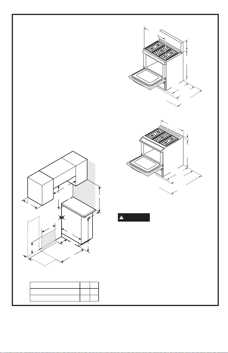
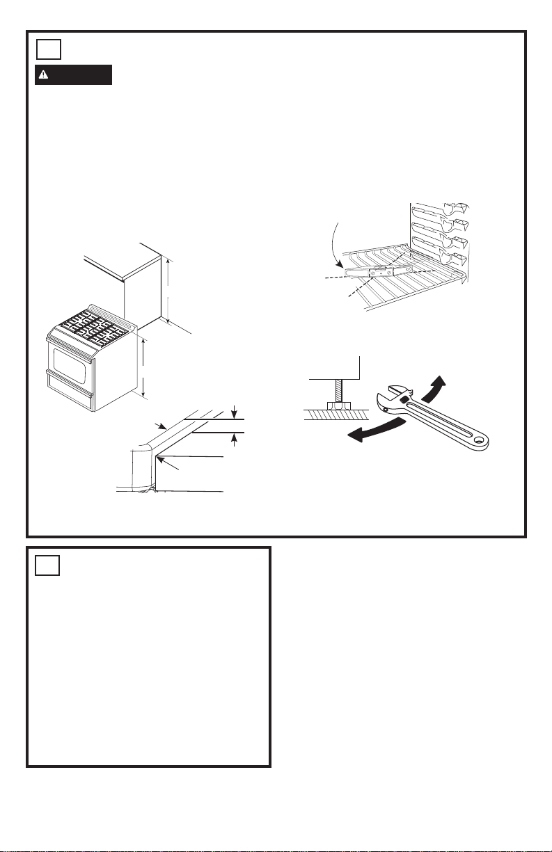
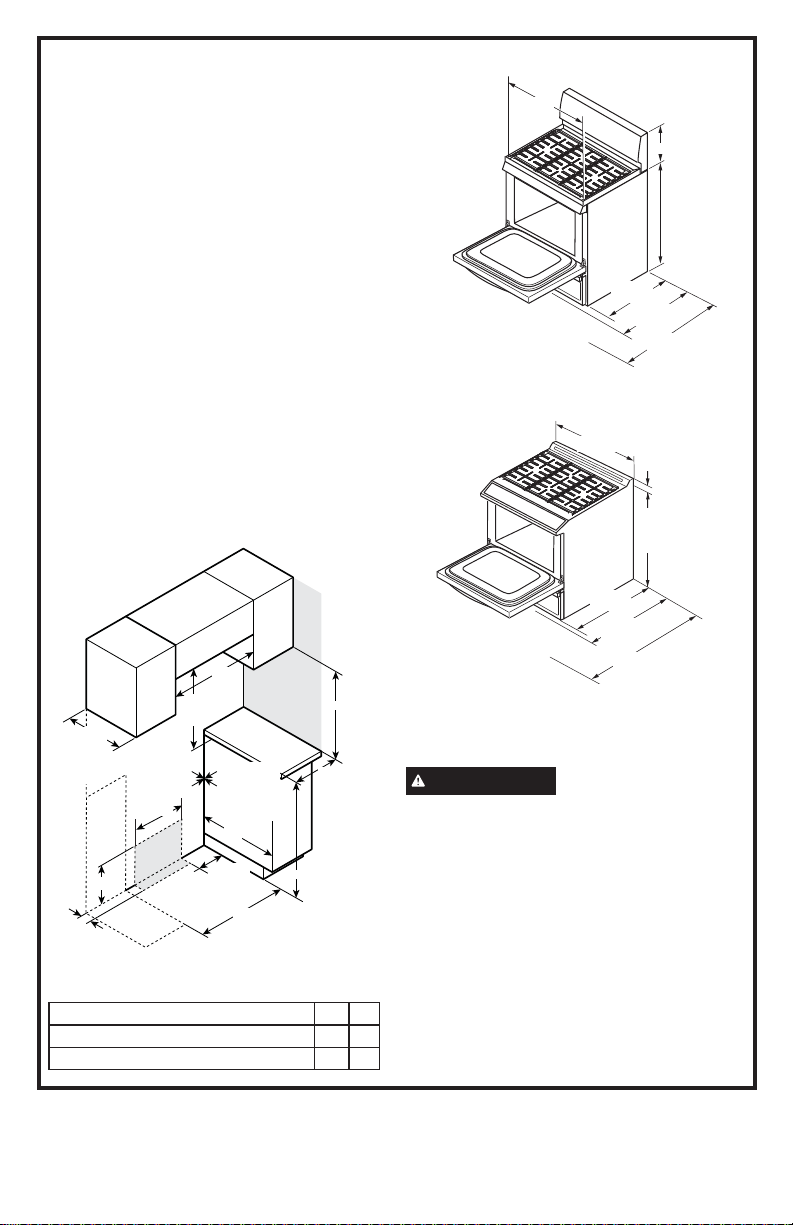
DIMENSIONS AND CLEARANCES
Provide adequate clearances between the
range and adjacent combustible surfaces.
These dimensions must be met for safe use of
your range.
$OORZ´FPPLQLPXPFOHDUDQFH
between burners and bottom of unprotected
ZRRGRUPHWDOFDELQHWRUDOORZD´
cm) minimum when bottom of wood or metal
FDELQHWLVSURWHFWHGE\QROHVVWKDQ´
mm) thick flame-retardant millboard covered
with no less than No. 28 MSG sheet metal
´>PP@WKLFN´
PPWKLFNVWDLQOHVVVWHHO´PP
DOXPLQXPRU´PPFRSSHU
Installation of a listed microwave oven or
cooking appliance over the cooktop shall
conform to the installation instructions packed
with that appliance.
)RULVODQGLQVWDOODWLRQPDLQWDLQ´PLQLPXP
from cutout to back edge of countertop and
´PLQLPXPIURPFXWRXWWRVLGHHGJHVRI
countertop.
Gas Pipe and Electrical Outlet Locations
CAUTION
To prevent drafts from
affecting burner operation, seal all openings
in floor under appliance and behind appliance
wall.
Before installing your range on linoleum or
any other synthetic floor covering, make sure
the floor covering can withstand 180°F without
shrinking, warping or discoloring. Do not install
the range over carpeting unless a sheet of
´WKLFNSO\ZRRGRUVLPLODULQVXODWRULVSODFHG
between the range and carpeting.
´
Minimum
to cabinets
below
cooktop
´VHH
note)
´
´
´
max to
cabinets
above
counter
B Right
side
A Left side
Minimum
to side wall
´
´
3 1/4´
´
´
´
´
Side
Wall
Gas
and
electrical
supply
Gas Range dimensions A B
4 Cooktop Burners ´ ´
5 Cooktop Burners ´ ´
NOTE: Minimum to bare cabinet
above: see Installation Instructions for
alternate installation configurations.
INSTALLATION AT HIGH
ALTITUDE
Over 6000ft, product configured for natural
gas or propane requires installation of
kit (WB28X47007 for natural gas and
JXBUFS04 for propane gas). Follow the
instructions included with the kit.
MOBILE HOME - ADDITIONAL
INSTALLATION REQUIREMENTS
The installation of this range must conform
to the Manufactured Home Construction
and Safety Standard, Title 24 CFR, Part
3280 (formerly the Federal Standard for
Mobile Home Construction and Saftey, Title
24, HUD Part 280). When such standard
is not applicable, use the Standard for
Manufactured Home Installations, ANSI
A225.1/NFPA 501A or with local codes.
When this range is installed in a mobile
home, it must be secured to the floor during
transit. Any method of securing the range
is adequate as long as it conforms to the
standards listed above.
1
REMOVE PACKAGING
MATERIALS:
Failure to remove packaging materials
could result in damage to the appliance.
Remove all packing parts from oven, racks,
heating elements and drawer. Also, remove
protective film and labels on the outer door,
cooktop and control panel.
Consider recycling options for your appliance
packaging material.
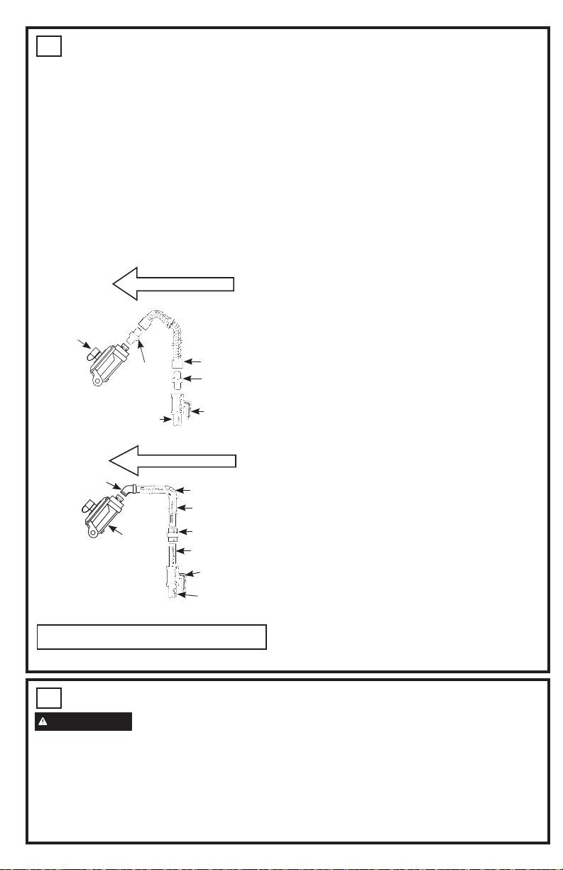
2
ATTACH REQUIRED FILLER
TRIM
For ALL front control installations, the
included filler trim must be installed. Remove
the two screws on rear trim indicated with
nearby arrows. Reuse these two screws to
attach the filler trim to the back of the range.
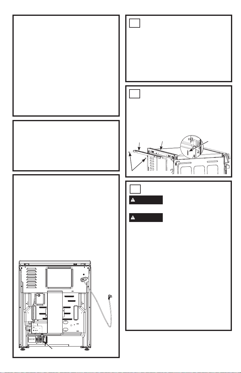
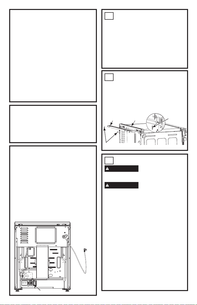
CONVERTING TO PROPANE GAS
(OR CONVERTING BACK TO
NATURAL GAS FROM PROPANE)
This range leaves the factory set for use
with natural gas. If you want to convert
to propane gas, the conversion must be
performed by a qualified propane gas
installer.
The conversion orifices and instructions can
be found in the owner’s manual packet.
Keep these instructions and all orifices in
case you want to convert back to natural gas.
Rear of Range
Pressure Regulator
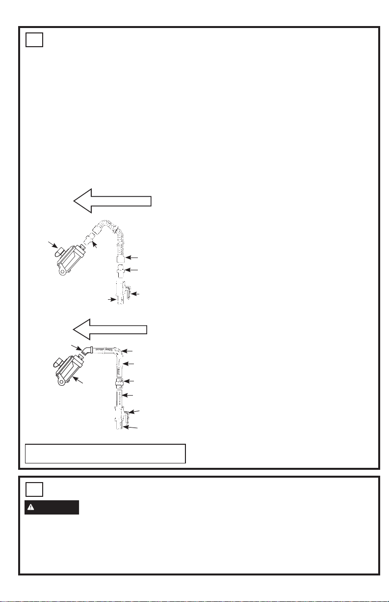
3
GAS SUPPLY
WARNING
Fire Hazard: Do not use a
flame to check for gas leaks.
WARNING
Explosion Hazard: Do not
exceed 25 ft-lbs of torque when making
gas line connections. Overtightening may
crack the pressure regulator resulting in
fire or explosion hazard.
Gas Pressure Regulator
You must use the gas pressure regulator
supplied with this range. For proper
operations the inlet pressure to the regulator
should be as follows:
Natural Gas:
0LQLPXPSUHVVXUH´RI:DWHU&ROXPQ
0D[LPXPSUHVVXUH´RI:DWHU&ROXPQ
Propane Gas:
0LQLPXPSUHVVXUH´RI:DWHU&ROXPQ
0D[LPXPSUHVVXUH´RI:DWHU&ROXPQ
If you are not sure about the inlet pressure,
contact local gas supplier.
FRONT CONTROL
´
´
to
´
´
with handle
´
26
´
w/o handle
48
1/2"
Door Open
REAR CONTROL
´WR
36 1/2
´
´
with handle
´
´
w/o handle
47
1/2"
Door Open
Screws
Filler Trim
Rear Trim
Arrows on
both sides
Back of Range
DIMENSIONS AND CLEARANCES
Provide adequate clearances between the
range and adjacent combustible surfaces.
These dimensions must be met for safe use of
your range.
$OORZ´FPPLQLPXPFOHDUDQFH
between burners and bottom of unprotected
ZRRGRUPHWDOFDELQHWRUDOORZD´
cm) minimum when bottom of wood or metal
FDELQHWLVSURWHFWHGE\QROHVVWKDQ´
mm) thick flame-retardant millboard covered
with no less than No. 28 MSG sheet metal
´>PP@WKLFN´
PPWKLFNVWDLQOHVVVWHHO´PP
DOXPLQXPRU´PPFRSSHU
Installation of a listed microwave oven or
cooking appliance over the cooktop shall
conform to the installation instructions packed
with that appliance.
)RULVODQGLQVWDOODWLRQPDLQWDLQ´PLQLPXP
from cutout to back edge of countertop and
´PLQLPXPIURPFXWRXWWRVLGHHGJHVRI
countertop.
Gas Pipe and Electrical Outlet Locations
CAUTION
To prevent drafts from
affecting burner operation, seal all openings
in floor under appliance and behind appliance
wall.
Before installing your range on linoleum or
any other synthetic floor covering, make sure
the floor covering can withstand 180°F without
shrinking, warping or discoloring. Do not install
the range over carpeting unless a sheet of
´WKLFNSO\ZRRGRUVLPLODULQVXODWRULVSODFHG
between the range and carpeting.
´
Minimum
to cabinets
below
cooktop
´VHH
note)
´
´
´
max to
cabinets
above
counter
B Right
side
A Left side
Minimum
to side wall
´
´
3 1/4´
´
´
´
´
Side
Wall
Gas
and
electrical
supply
Gas Range dimensions A B
4 Cooktop Burners ´ ´
5 Cooktop Burners ´ ´
NOTE: Minimum to bare cabinet
above: see Installation Instructions for
alternate installation configurations.
INSTALLATION AT HIGH
ALTITUDE
Over 6000ft, product configured for natural
gas or propane requires installation of
kit (WB28X47007 for natural gas and
JXBUFS04 for propane gas). Follow the
instructions included with the kit.
MOBILE HOME - ADDITIONAL
INSTALLATION REQUIREMENTS
The installation of this range must conform
to the Manufactured Home Construction
and Safety Standard, Title 24 CFR, Part
3280 (formerly the Federal Standard for
Mobile Home Construction and Saftey, Title
24, HUD Part 280). When such standard
is not applicable, use the Standard for
Manufactured Home Installations, ANSI
A225.1/NFPA 501A or with local codes.
When this range is installed in a mobile
home, it must be secured to the floor during
transit. Any method of securing the range
is adequate as long as it conforms to the
standards listed above.
1
REMOVE PACKAGING
MATERIALS:
Failure to remove packaging materials
could result in damage to the appliance.
Remove all packing parts from oven, racks,
heating elements and drawer. Also, remove
protective film and labels on the outer door,
cooktop and control panel.
Consider recycling options for your appliance
packaging material.
2
ATTACH REQUIRED FILLER
TRIM
For ALL front control installations, the
included filler trim must be installed. Remove
the two screws on rear trim indicated with
nearby arrows. Reuse these two screws to
attach the filler trim to the back of the range.
CONVERTING TO PROPANE GAS
(OR CONVERTING BACK TO
NATURAL GAS FROM PROPANE)
This range leaves the factory set for use
with natural gas. If you want to convert
to propane gas, the conversion must be
performed by a qualified propane gas
installer.
The conversion orifices and instructions can
be found in the owner’s manual packet.
Keep these instructions and all orifices in
case you want to convert back to natural gas.
Rear of Range
Pressure Regulator
3
GAS SUPPLY
WARNING
Fire Hazard: Do not use a
flame to check for gas leaks.
WARNING
Explosion Hazard: Do not
exceed 25 ft-lbs of torque when making
gas line connections. Overtightening may
crack the pressure regulator resulting in
fire or explosion hazard.
Gas Pressure Regulator
You must use the gas pressure regulator
supplied with this range. For proper
operations the inlet pressure to the regulator
should be as follows:
Natural Gas:
0LQLPXPSUHVVXUH´RI:DWHU&ROXPQ
0D[LPXPSUHVVXUH´RI:DWHU&ROXPQ
Propane Gas:
0LQLPXPSUHVVXUH´RI:DWHU&ROXPQ
0D[LPXPSUHVVXUH´RI:DWHU&ROXPQ
If you are not sure about the inlet pressure,
contact local gas supplier.
FRONT CONTROL
´
´
to
´
´
with handle
´
26
´
w/o handle
48
1/2"
Door Open
REAR CONTROL
´WR
36 1/2
´
´
with handle
´
´
w/o handle
47
1/2"
Door Open
Screws
Filler Trim
Rear Trim
Arrows on
both sides
Back of Range
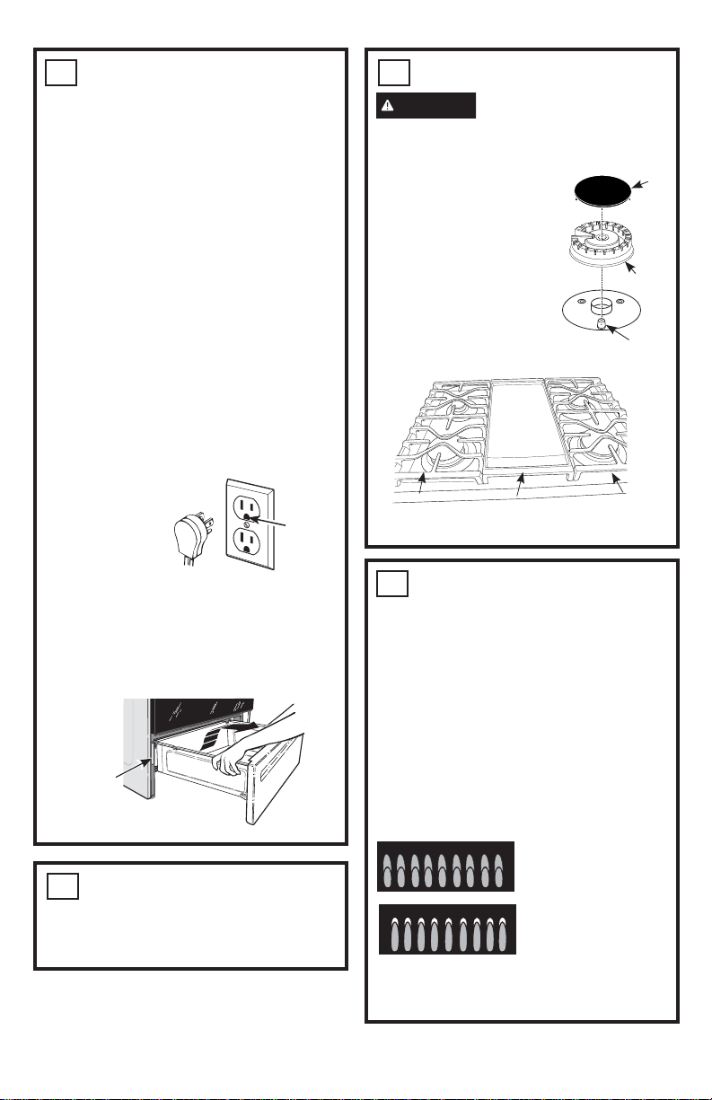
6
SURFACE BURNERS
WARNING
Fire or Explosion
Hazard:
Do not operate the burner without all
burner parts in place.
A. Burners - Place
surface burners into
corresponding positions
on cooktop.
B. Caps - Place caps on
proper size burner.
C. Grates - The left
and right grates are
interchangeable. Place
the grates on the cooktop.
3
GAS SUPPLY (Cont.)
Shut off the main gas supply valve before
disconnecting the old range and leave it off until
the new hook-up has been completed. Don’t
forget to relight the pilot on other gas appliances
when you turn the gas back on.
Because hard piping restricts movement of
the range, the use of a CSA International-
certified flexible metal appliance connector is
recommended unless local codes require a
hard-piped connection.
If the hard piping method is used, you must
carefully align the pipe; the range cannot be
moved after the connection is made.
CONNECTOR HOOKUP
To prevent gas leaks, put pipe joint compound
on, or wrap pipe thread tape with Teflon*
around, all male (external) pipe threads.
A. Install a manual shut-off valve in the gas line
in an easily accessed location outside of the
range. Make sure everyone operating the
range knows where and how to shut off the
gas supply to the range.
%,QVWDOOPDOH´IODUHXQLRQDGDSWHUWRWKH
´137LQWHUQDOWKUHDGDWLQOHWRIUHJXODWRU
Use a backup wrench on the regulator fitting
to avoid damage.
&,QVWDOOPDOH´RU´IODUHXQLRQDGDSWHU
to the NPT internal thread of the manual
shut-off valve, taking care to back-up the
shut-off valve to keep it from turning.
D. Connect flexible metal appliance connector to
the adapter on the range. Position range to
permit connection at the shut-off valve.
E. When all connections have been made, make
sure all range controls are in the off position
and turn on the main gas supply valve.
Use a liquid leak detector at all joints and
connections to check for leaks in the system.
When using pressures greater than 1/2 psig
to pressure test the gas supply system of the
residence, disconnect the range and individual
shut-off valve from the gas supply piping. When
using pressures of 1/2 psig or less to pressure
test the gas supply system, simply isolate the
range from the gas supply system by closing the
individual shut-off valve.
When checking for proper operation of the
UHJXODWRUWKHLQOHWSUHVVXUHPXVWEHDWOHDVW´
greater than the operating (manifold) pressure
as given on rating label of product.
*Teflon: Registered trademark of DuPont
4
ELECTRICAL CONNECTIONS
(Cont.)
Grounding
The power cord of this appliance is equipped
with a three-prong (grounding) plug which
plugs into a standard three-prong grounding
wall receptacle to minimize the possibility of
electric shock hazard from this appliance.
The customer should have the wall
receptacle and circuit checked by a qualified
electrician to make sure the receptacle is
properly grounded.
Where a standard two-prong wall
receptacle is encountered, it is the personal
responsibility and obligation of the customer
to have it replaced with a properly grounded
three-prong wall receptacle.
DO NOT, UNDER ANY CIRCUMSTANCES,
CUT OR REMOVE THE THIRD (GROUND)
PRONG FROM THE POWER CORD. DO
NOT USE AN ADAPTER. DO NOT USE AN
EXTENSION CORD.
NOTE: Ground
Fault Circuit
Interrupters
(GFCI’s) will not
affect performance
of the gas range
if operated on a GFCI-protected circuit but
occasional nuisance tripping of the GFCI
breaker is possible.
The rating plate is located on the frame
surrounding the drawer.
4
ELECTRICAL CONNECTIONS
WARNING
Shock Hazard: This
appliance must be properly grounded. Failure to
do so can result in electric shock.
Electrical Requirements - 120-volt, 60 Hertz,
properly grounded circuit protected by a 15-amp
or 20-amp circuit breaker or time delay fuse. It
is recommended that a separate circuit serving
only this range be provided.
NOTE: Use of automatic, wireless, or wired
external switches that shut off power to the
appliance are not recommended for this product.
Pressure
regulator
Gas Flow into Range
Flex
connector
(6 ft. max.)
Adapter
´RU´
Gas pipe
Adapter
Gas
shut-off
valve
Flexible
Option
Gas Flow into Range
Pressure
regulator
Elbow
Elbow
Nipple
Union
Nipple
Gas shut-off
valve
´RU´
Gas pipe
Rigid Pipe
Option
Installer: Inform the consumer of the
location of the gas shut-off valve.
Ensure
proper
ground
exists
before
use
Rating
plate
5
INSTALL KNOBS
Ŷ5HPRYHDOONQREVIURPSDFNDJLQJ
Ŷ ,QVWDOOWKHNQREVRQWRWKHFRRNWRSEXUQHU
shafts.
Electrode
Cap
Burner
Left
Grate
Right
Grate
Center
Grate or Griddle
(on some models)
7
CHECK SURFACE BURNERS
Push and turn a knob to the LITE position.
A clicking sound indicates proper operation
of the ignition system. When lighting any
burner, sparks will appear at all burners
but gas flows from only the one selected.
Once air is purged from the supply line,
burner should light within 4 seconds. After
burner lights, rotate the knob out of the LITE
position. Try each burner in succession until
all burners have been checked.
Quality of Flames
Determine the quality of flames visually.
Normal burner flames should look like (A)
or (B).
Normal flames may show signs of an orange
tint when well heated or signs of flickering
orange due to particles in the gas or air.
(A) Soft blue flames—
Normal for natural gas
(B) Yellow tips on
outer cones—
Normal for propane gas
INSTALLATION INSTRUCTION
31-2001195 Rev. 1 09-23 GEA
10
LEVEL THE RANGE
WARNING
Never completely remove the
leveling leg as the range will not be secured to
the anti-tip device properly.
A. Plug in the unit and remove the drawer.
Refer to your owner’s manual for
instructions.
B. Measure the height of your countertop at the
rear of the opening (X).
C. Adjust two rear leveling legs so that the rear
of cooktop is higher than or equal to the
counter (Y).
D. Slide unit into place taking care to engage
the leveling legs in the anti-tip device.
E. Look under the unit and verify that the rear
leg is fully engaged with the anti-tip device.
If not, remove the unit and adjust the height
of the rear leg so that it is properly engaged.
F. Install racks in the oven.
G. Check for levelness by placing a spirit
level on one of the oven shelves. Take two
readings—with the level placed diagonally
first in one direction and then the other.
H. Use an adjustable wrench to adjust the front
leveling legs until the range is level.
I. Position cord so that it does not interfere
with drawer.
J. Reinstall the drawer. Refer to your owner’s
manual for instructions.
X
Y
Cooktop
0" or Greater
Counter
Spirit level
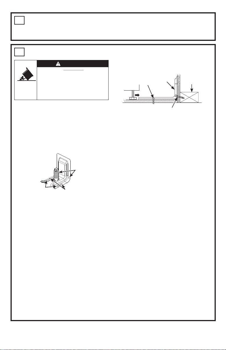
9
ANTI-TIP DEVICE INSTALLATION
To reduce the risk of tipping the range, the
range must be secured by a properly installed
anti-tip bracket. Remove any currently used
anti-tip bracket and install with the provided
anti-tip bracket.
1. IMPORTANT: Determine the final location
of the range before attempting to install the
bracket. Remove existing anti-tip bracket
from install space, if present.
a. Place the bracket on the floor with the
back edge against the rear wall. If the
range does not reach the rear wall, align
the back edge of the bracket with the rear
panel of the range in its final location.
If bracket does not touch the rear wall,
you MUST screw bracket to FLOOR as
described in Step 2.
b. Position the side of the bracket against
either the left or right cabinet. If there is
no adjacent cabinet, align the edge of
the bracket with the side panel of the
range in its final location. If the countertop
overhangs The cabinet, offset the bracket
from the cabinet by the amount of
overhang.
c. Mark the location for the pair of holes to be
used (see illustration above).
NOTE: For FLOOR installation use either
Loc A or B. For REAR WALL installation
use Loc C.
2. The bracket must be screwed to either the
FLOOR or REAR WALL.
FLOOR Installation:
WOOD FLOOR: Use the screws provided to
secure the bracket using the pair of marked
holes (either Loc A or B).
CONCRETE FLOOR: Using a concrete
ELWGULOOD´SLORWKROH´GHHSLQWRWKH
concrete at the center of each of the marked
holes (either Loc A or B). Use the screws
provided to secure the bracket into the floor.
REAR WALL Installation:
Use the 2 screws provided to secure the
bracket using the pair of marked holes at
Loc C. The screws MUST enter into a wood
sill plate. If the wall contains any metal studs
or similar materials, then the floor must be
used.
3. To check if the bracket is installed and
engaged properly, look underneath the
range to see that the rear leveling leg is
engaged in the bracket. On some models,
the storage drawer or kick panel can be
removed for easy inspection. If visual
inspection is not possible, slide the range
forward, confirm the anti-tip bracket is
securely attached to the floor or wall, and
slide the range back so the rear leveling
leg is under the anti-tip bracket. If your
range is removed for cleaning, servicing,
or any reason, be sure the anti-tip device
is reengaged properly when the range is
replaced. Failure to take this precaution
could result in tipping of the range and can
result in death or serious burns to children
or adults. Never completely remove the
leveling legs or the range will not be secured
to the anti-tip device properly.
Anti-Tip
Bracket Kit
Included
Loc A
Loc B
Loc C
Two screws must enter floor
at Loc A or B or wall at Loc C.
Rear Wall
Screw must enter
wood or concrete
Attachment to Floor or Rear Wall
Wall Sill Plate
Screw must enter wood
Bracket
8
CHECK BAKE AND BROIL BURNERS
Ŷ6HW%DNHIXQFWLRQWR)%XUQHUVKRXOG
light in 30 to 60 seconds.
Ŷ6HWEURLOWR%URLO+L0RGHOVZLWKDJDV
burner should light in 30 to 60 seconds.
11
FINAL INSTALLATION
CHECKLIST
Ŷ0DNHVXUHWKHIORZRIFRPEXVWLRQDQG
ventilation air to the range is unobstructed.
Ŷ&KHFNWKDWDOOSDFNLQJPDWHULDOVDQGWDSH
have been removed. This will include
tape on metal panel under control knobs
(if applicable), adhesive tape, wire ties,
cardboard and protective plastic. Failure
to remove these materials could result
in damage to the appliance once the
appliance has been turned on and surfaces
have heated.
Ŷ0DNHVXUHDOOFRQWUROVDUHOHIWLQWKHRII
position.
Raise
Range
Lower
Range
• A child or adult can tip the range and be killed.
• Install the anti-tip bracket provided with the unit
to the wall or floor.
• Engage the range to the anti-tip bracket by sliding the
range back such that the foot is engaged.
• Re-engage the anti-tip bracket if the range is moved.
• Failure to do so can result in death or serious burns
to children or adults.
Tip-Over Hazard
WARNING
INSTALLATION INSTRUCTION
31-2001195 Rev. 1 09-23 GEA
10
LEVEL THE RANGE
WARNING
Never completely remove the
leveling leg as the range will not be secured to
the anti-tip device properly.
A. Plug in the unit and remove the drawer.
Refer to your owner’s manual for
instructions.
B. Measure the height of your countertop at the
rear of the opening (X).
C. Adjust two rear leveling legs so that the rear
of cooktop is higher than or equal to the
counter (Y).
D. Slide unit into place taking care to engage
the leveling legs in the anti-tip device.
E. Look under the unit and verify that the rear
leg is fully engaged with the anti-tip device.
If not, remove the unit and adjust the height
of the rear leg so that it is properly engaged.
F. Install racks in the oven.
G. Check for levelness by placing a spirit
level on one of the oven shelves. Take two
readings—with the level placed diagonally
first in one direction and then the other.
H. Use an adjustable wrench to adjust the front
leveling legs until the range is level.
I. Position cord so that it does not interfere
with drawer.
J. Reinstall the drawer. Refer to your owner’s
manual for instructions.
X
Y
Cooktop
0" or Greater
Counter
Spirit level
9
ANTI-TIP DEVICE INSTALLATION
To reduce the risk of tipping the range, the
range must be secured by a properly installed
anti-tip bracket. Remove any currently used
anti-tip bracket and install with the provided
anti-tip bracket.
1. IMPORTANT: Determine the final location
of the range before attempting to install the
bracket. Remove existing anti-tip bracket
from install space, if present.
a. Place the bracket on the floor with the
back edge against the rear wall. If the
range does not reach the rear wall, align
the back edge of the bracket with the rear
panel of the range in its final location.
If bracket does not touch the rear wall,
you MUST screw bracket to FLOOR as
described in Step 2.
b. Position the side of the bracket against
either the left or right cabinet. If there is
no adjacent cabinet, align the edge of
the bracket with the side panel of the
range in its final location. If the countertop
overhangs The cabinet, offset the bracket
from the cabinet by the amount of
overhang.
c. Mark the location for the pair of holes to be
used (see illustration above).
NOTE: For FLOOR installation use either
Loc A or B. For REAR WALL installation
use Loc C.
2. The bracket must be screwed to either the
FLOOR or REAR WALL.
FLOOR Installation:
WOOD FLOOR: Use the screws provided to
secure the bracket using the pair of marked
holes (either Loc A or B).
CONCRETE FLOOR: Using a concrete
ELWGULOOD´SLORWKROH´GHHSLQWRWKH
concrete at the center of each of the marked
holes (either Loc A or B). Use the screws
provided to secure the bracket into the floor.
REAR WALL Installation:
Use the 2 screws provided to secure the
bracket using the pair of marked holes at
Loc C. The screws MUST enter into a wood
sill plate. If the wall contains any metal studs
or similar materials, then the floor must be
used.
3. To check if the bracket is installed and
engaged properly, look underneath the
range to see that the rear leveling leg is
engaged in the bracket. On some models,
the storage drawer or kick panel can be
removed for easy inspection. If visual
inspection is not possible, slide the range
forward, confirm the anti-tip bracket is
securely attached to the floor or wall, and
slide the range back so the rear leveling
leg is under the anti-tip bracket. If your
range is removed for cleaning, servicing,
or any reason, be sure the anti-tip device
is reengaged properly when the range is
replaced. Failure to take this precaution
could result in tipping of the range and can
result in death or serious burns to children
or adults. Never completely remove the
leveling legs or the range will not be secured
to the anti-tip device properly.
Anti-Tip
Bracket Kit
Included
Loc A
Loc B
Loc C
Two screws must enter floor
at Loc A or B or wall at Loc C.
Rear Wall
Screw must enter
wood or concrete
Attachment to Floor or Rear Wall
Wall Sill Plate
Screw must enter wood
Bracket
8
CHECK BAKE AND BROIL BURNERS
Ŷ6HW%DNHIXQFWLRQWR)%XUQHUVKRXOG
light in 30 to 60 seconds.
Ŷ6HWEURLOWR%URLO+L0RGHOVZLWKDJDV
burner should light in 30 to 60 seconds.
11
FINAL INSTALLATION
CHECKLIST
Ŷ0DNHVXUHWKHIORZRIFRPEXVWLRQDQG
ventilation air to the range is unobstructed.
Ŷ&KHFNWKDWDOOSDFNLQJPDWHULDOVDQGWDSH
have been removed. This will include
tape on metal panel under control knobs
(if applicable), adhesive tape, wire ties,
cardboard and protective plastic. Failure
to remove these materials could result
in damage to the appliance once the
appliance has been turned on and surfaces
have heated.
Ŷ0DNHVXUHDOOFRQWUROVDUHOHIWLQWKHRII
position.
Raise
Range
Lower
Range
• A child or adult can tip the range and be killed.
• Install the anti-tip bracket provided with the unit
to the wall or floor.
• Engage the range to the anti-tip bracket by sliding the
range back such that the foot is engaged.
• Re-engage the anti-tip bracket if the range is moved.
• Failure to do so can result in death or serious burns
to children or adults.
Tip-Over Hazard
WARNING
FORMA ADECUADA DE DESCARTAR
SU ELECTRODOMÉSTICO
Descarte o recicle su electrodoméstico de
acuerdo con las Regulaciones Federales y
Locales. Comuníquese con las autoridades
locales para descartar o reciclar su
electrodoméstico de forma ambientalmente
segura.
Instrucciones de Instalación
Estufa a Gas
EN EL COMMONWEALTH DE
MASSACHUSETTS
Ŷ(VWHSURGXFWRGHEHVHULQVWDODGRSRUXQ
plomero licenciado o un mecánico gasista.
Ŷ$OXVDUYiOYXODVGHFLHUUHGHJDVWLSREDOyQ
deberán ser del tipo de manija T.
Ŷ$OXVDUXQFRQHFWRUGHJDVIOH[LEOHQR
GHEHUiH[FHGHUORVSLHV
ANTES DE COMENZAR
Lea estas instrucciones por completo y con
detenimiento.
• IMPORTANTE – Guarde estas instruc-
ciones para el uso de inspectores locales.
• IMPORTANTE – Cumpla con todos los
FyGLJRV\RUGHQDQ]DVYLJHQWHV
• Nota al instalador –$VHJ~UHVHGHGHMDU
estas instrucciones con el Consumidor.
• Nota al consumidor –&RQVHUYHHVWDV
instrucciones para referencia futura.
• Servicio Técnico – (OGLDJUDPDHOpFWULFR
se encuentra en el sobre adherido al panel del
ODWHUDOL]TXLHUGRDOVHUUHWLUDGRHOFDMyQ
/DFRUUHFWDLQVWDODFLyQGHOSURGXFWRHVUHV-
ponsabilidad del instalador.
• Si se producen fallas en el producto debido
DXQDLQVWDODFLyQLQDGHFXDGDOD*DUDQWtD
no cubrirá las mismas.
• IMPORTANTE — Retire todo el
material de embalaje y material escrito
del horno antes de conectar el gas y el
suministro de corriente a la cocina.
• IMPORTANTE — 3DUDHYLWDUGDxRV
VREUHORVJDELQHWHVFRQWUROHFRQVX
FRQVWUXFWRURSURYHHGRUGHJDELQHWHVTXH
ORVPDWHULDOHVXVDGRVQRSURGX]FDQGHV-
FRORUDFLyQGHVODPLQDFLyQQLJHQHUHQRWURV
GDxRV(VWHKRUQRIXHGLVHxDGRGHDFXHUGR
FRQORVUHTXLVLWRVGH8/\&6$,QWHUQDWLRQDO
\FXPSOHFRQODVWHPSHUDWXUDVPi[LPDV
permitidas para gabinetes de madera de C).
• Nivel de capacidad –/DLQVWDODFLyQ
de este aparato requiere capacidades
mecánicas básicas y capacidades eléctricas
DYDQ]DGDV
ADVERTENCIA
Retire el soporte
DQWLYROFDGXUDVGHOHVSDFLRGHLQVWDODFLyQ
en caso de estar presente.
ADVERTENCIA
RIESGO DE
INCENDIO O EXPLOSIÓN
6LODLQIRUPDFLyQGHHVWHPDQXDOQRVH
VLJXHH[DFWDPHQWHVHSRGUiSURGXFLUXQ
LQFHQGLRRH[SORVLyQRFDVLRQDQGRGDxRV
VREUHODSURSLHGDGOHVLRQHVRODPXHUWH
/DLQVWDODFLyQGHEHUiQVHUUHDOL]DGDVSRU
un instalador calificado.
Lea estas instrucciones en su totalidad y
atentamente.
(VWDFRFLQDVHGHEHUiLQVWDODUGH
DFXHUGRFRQORVFyGLJRVORFDOHVRHQ
ODDXVHQFLDGHFyGLJRVORFDOHVFRQHO
&yGLJRGH*DV&RPEXVWLEOH1DFLRQDO
$16,=1)3$~OWLPDHGLFLyQ
(Q&DQDGiODLQVWDODFLyQGHEHUiVHU
FRQIRUPHFRQHO&yGLJRGH,QVWDODFLyQ
GH*DV1DWXUDODFWXDO&$1&*$%
RHO&yGLJRGH,QVWDODFLyQGH3URSDQR
DFWXDO&$1&*$%\FRQORV
FyGLJRVORFDOHVFXDQGRFRUUHVSRQGD
(VWDFRFLQDIXHGLVHxDGD\FHUWLILFDGDSRU
&6$,QWHUQDWLRQDOGHDFXHUGRFRQ$16,
=~OWLPDHGLFLyQ\FRQOD&DQDGLDQ
*DV$VVRFLDWLRQ$VRFLDFLyQGH*DVGH
&DQDGi&$1&*$~OWLPDHGLFLyQ
$OLQVWDODUXQHOHFWURGRPpVWLFRDJDVHO
XVRGHFRQHFWRUHVIOH[LEOHVYLHMRVSXHGH
ocasionar pérdidas y lesiones personales.
6LHPSUHXVHXQFRQHFWRUIOH[LEOH18(92
La prueba de goteras del electrodoméstico
VHGHEHUiUHDOL]DUGHDFXHUGRFRQODV
instrucciones del fabricante.
La cocina deberá estar correctamente
conectada a tierra de acuerdo con los
FyGLJRV\RUGHQDQ]DVORFDOHVRHQ
DXVHQFLDGHFyGLJRVORFDOHVGHDFXHUGR
FRQHO&yGLJR1DFLRQDOGH(OHFWULFLGDG
1DWLRQDO(OHFWULF&RGH$16,1)3$
12~OWLPDHGLFLyQ(Q&DQDGiOD
FRQH[LyQDWLHUUDVHGHEHUiUHDOL]DUGH
DFXHUGRFRQOD3DUWHGHO&yGLJRGH
(OHFWULFLGDGGH&DQDGi&6$&\RORV
FyGLJRVORFDOHV&RQVXOWHODV&RQH[LRQHV
(OpFWULFDV
1RLQVWDOHHVWHSURGXFWRFRQXQDFDPSDQD
con cortina de aire u otra campana de
FRFLQDTXHIXQFLRQHOOHYDQGRDLUHDOD
SODFDGHFRFFLyQ(OIOXMRGHDLUHSRGUi
interferir en el funcionamiento de los
TXHPDGRUHVGHJDVSURGXFLHQGRULHVJRV
GHLQFHQGLRRH[SORVLyQ
MATERIALES NECESARIOS
Ŷ9iOYXODGHFLHUUHSDUDWXEHUtDGHJDV
Ŷ6HOODGRUSDUDMXQWDGHWXEHUtDR8/±
FLQWDSDUDWXEHUtDDSUREDGDFRQ7HIOyQ
UHVLVWHQWHDODDFFLyQGHJDVHVQDWXUDOHV
o propano
Ŷ&RQHFWRUSDUDDUWHIDFWRPHWiOLFRIOH[LEOH
´,'6HUHFRPLHQGDXQDORQJLWXGGH
SLHVSDUDXQDIiFLOLQVWDODFLyQSHURRWUDV
ORQJLWXGHVVRQDFHSWDEOHV1XQFDXVHXQ
FRQHFWRUYLHMRDOLQVWDODUXQDFRFLQDQXHYD
Ŷ$GDSWDGRUSDUDXQLyQFyQLFDSDUDOD
FRQH[LyQDOVXPLQLVWURGHJDV´Rò´
137[ò´,'
Ŷ$GDSWDGRUSDUDXQLyQFyQLFDSDUDOD
FRQH[LyQDOUHJXODGRUGHSUHVLyQHQOD
FRFLQD´Rò´137[ò´,'
Ŷ'HWHFWRUGHSpUGLGDGHOtTXLGRRDJXDFRQ
MDEyQ
7HIOyQ0DUFDUHJLVWUDGDSRU'X3RQW
HERRAMIENTAS NECESARIAS
1LYHO
Destornillador Philips
/iSL]\UHJOD
Taladro
/ODYHFRQH[WUHPR
abierto o ajustable
/ODYHSDUDWXEHUtD
XQDGHUHSXHVWR
Gafas de seguridad
/ODYHGHWXHUFDV
GHó´
¿Preguntas? Llame a GE Appliances al 800.GE.CARES (800.432.2737) o visita
GEAppliances.com.
PARA SU SEGURIDAD:
6LQRUHFLELyXQVRSRUWHDQWLYROFDGXUDV
FRQVXFRPSUDOODPHDO
para recibir uno sin costo. Para recibir
LQVWUXFFLRQHVGHLQVWDODFLyQGHOVRSRUWHYLVLWH
GEAppliances.com.
Retire cualquier
soporte
DQWLYROFDGXUDV
actualmente
usado y realice
ODLQVWDODFLyQ
con el soporte
DQWLYROFDGXUDV\ORV
WRUQLOORVSURYLVWRV
ADVERTENCIA
$QWHVGHFRPHQ]DUOD
LQVWDODFLyQDSDJXHHO
encendido en el panel
GHVHUYLFLR\EORTXHHHO
PHGLRGHGHVFRQH[LyQ
GHOVHUYLFLRDILQGH
HYLWDUTXHHOHQFHQGLGR
VHDFWLYHGHIRUPD
accidental. Cuando el
PHGLRGHGHVFRQH[LyQ
GHOVHUYLFLRQRVHSXHGD
EORTXHDUDMXVWHGH
manera segura un ítem
GHDGYHUWHQFLDTXHHVWp
ELHQYLVLEOHWDOFRPR
XQDHWLTXHWDVREUHHO
SDQHOGHVHUYLFLR
Soporte
$QWLYROFDGXUDV
y Tornillos
,QFOXLGRV
• Un niño o adulto pueden volcar la cocina y morir.
• Instale el soporte anti-volcaduras provisto con
la unidad sobre la pared o el piso.
•
Asegúrese la estufa al soporte anti-volcaduras deslizando
la unidad hacia atras de tal manera que la pata niveladora
sea enganchada.
• Vuelva a adherir el soporte anti-volcaduras si la estufa
se mueve de lugar.
• Si esto no se hace, se podrá producir la muerte o
quemaduras graves en niños o adultos.
Riesgo de Caída
ADVERTENCIA
DIMENSIONES Y ESPACIOS
Deje el espacio adecuado entre la cocina y las
VXSHUILFLHVFRPEXVWLEOHVDG\DFHQWHV(VWDV
dimensiones se deberán cumplir para un uso
seguro de su cocina.
'HMHXQHVSDFLRPtQLPRGH´FPHQWUH
los quemadores y la parte inferior del gabinete
GHPDGHUDRPHWDOVLQSURWHFFLyQRGHMHXQ
HVSDFLRPtQLPRGH´FPFXDQGROD
parte inferior del gabinete de madera o metal
HVWpSURWHJLGRSRUQRPHQRVGH´PP
GHFDUWyQGHUHWDUGRGHLQFHQGLRVFXELHUWDSRU
QRPHQRVTXHXQDOiPLQDPHWiOLFDGH06*
´PPGHJURVRU´PPGH
JURVRUGHDFHURLQR[LGDEOH´PPGH
DOXPLQLRR´PPGHFREUH
/DLQVWDODFLyQGHXQKRUQRPLFURRQGDVRGH
XQHOHFWURGRPpVWLFRGHFRFFLyQTXHILJXUHQ
en la lista sobre la parte superior de la cocina
deberá cumplir con las instrucciones de
LQVWDODFLyQSURYLVWDVFRQHOHOHFWURGRPpVWLFR
3DUDODLQVWDODFLyQGHODLVODGHMHXQHVSDFLR
PtQLPRGHò´GHVGHODDEHUWXUDKDVWDHO
H[WUHPRWUDVHURGHODPHVDGD\XQPtQLPR
GH´GHVGHODDEHUWXUDKDVWDORVH[WUHPRV
laterales de la mesada.
UBICACIONES DE LA TUBERÍA DE GAS Y
DEL TOMACORRIENTE ELÉCTRICO
PRECAUCIÓN
3DUDHYLWDUTXHXQD
corriente de aire afecte el funcionamiento del
TXHPDGRUVHOOHWRGDVODVDEHUWXUDVVREUHHO
piso debajo del electrodoméstico y detrás de la
pared del mismo.
$QWHVGHLQVWDODUVXFRFLQDVREUHOLQyOHR\
FXDOTXLHURWURUHYHVWLPLHQWRGHSLVRVLQWpWLFR
DVHJ~UHVHGHTXHHOUHYHVWLPLHQWRGHOSLVR
UHVLVWDORV)VLQFRQWUDHUVHFRPEDUVH
RGHVFRORUDUVH1RLQVWDOHODFRFLQDVREUH
DOIRPEUDVDPHQRVTXHKD\DXQDKRMDGH
FRQWUDFKDSDGRGHXQJURVRUGHó´RXQ
aislante similar entre la cocina y la alfombra.
´$OWXUD
mínima hasta
los gabinetes
debajo de la
superficie
GHFRFFLyQ
´
´
´Pi[LPD
hasta los
gabinetes
sobre la
mesada
%/DGR
derecho
$/DGR
L]TXLHUGR
$OWXUD
mínima
hasta la
pared lateral
´
´
´
´
´
´
´
Pared
Lateral
Suministro
de gas y
electricidad
´YHU
nota)
Dimensiones de la Estufa a Gas A B
4XHPDGRUHVGHOD3ODFDGH&RFFLyQ ´ ´
4XHPDGRUHVGHOD3ODFDGH&RFFLyQ ´ ´
NOTA: 0tQLPRKDVWDHOJDELQHWHGHVFXELHUWRDUULED
FRQVXOWHODV,QVWUXFFLRQHVGH,QVWDODFLyQSDUDDFFHGHU
DFRQILJXUDFLRQHVGHLQVWDODFLyQDOWHUQDWLYDV
INSTALACIÓN EN ALTITUDES
ELEVADA
$PiVGHSLHVHOSURGXFWRFRQILJXUDGR
para gas natural o propano requiere la
LQVWDODFLyQGHONLW:%;SDUDJDV
QDWXUDO\-;%8)6SDUDJDVSURSDQR6LJD
ODVLQVWUXFFLRQHVLQFOXLGDVFRQHONLW
CASA RODANTE – REQUISITOS
DE INFORMACIÓN ADICIONAL
(VWDFRFLQDVHGHEHUiLQVWDODUFRQIRUPHFRQ
HO(VWiQGDUGH&RQVWUXFFLyQ\6HJXULGDG
SDUD+RJDU7tWXOR&)53LH]D
DQWHULRUPHQWHHO(VWiQGDU)HGHUDOSDUD
OD&RQVWUXFFLyQ\6HJXULGDGGH&DVDV
5RGDQWHV)HGHUDO6WDQGDUGIRU0RELOH
+RPH&RQVWUXFWLRQDQG6DIHW\7tWXOR
+8'3DUWH&XDQGRGLFKRHVWiQGDU
QRVHDDSOLFDEOHXVHHOHVWiQGDUSDUDODV
,QVWDODFLRQHVGH&DVDV)DEULFDGDV$16,
$1)3$$RFRQFyGLJRVORFDOHV
Cuando la cocina es instalada en una casa
PyYLOVHGHEHUiDVHJXUDUDOSLVRGXUDQWH
el tránsito. Cualquier método para asegurar
ODFRFLQDHVDGHFXDGRVLHPSUH\FXDQGR
se realice conforme con los estándares que
ILJXUDQDFRQWLQXDFLyQ
1
QUITE LOS MATERIALES DE
ENVÍO:
1RTXLWDUORVPDWHULDOHVGHHPSDTXHSXHGH
SURYRFDUGDxRVDOHOHFWURGRPpVWLFR4XLWH
WRGDVODVSDUWHVGHHPSDTXHGHOKRUQR
EDQGHMDVHOHPHQWRVFDOHQWDGRUHV\FDMyQ
7DPELpQTXLWHODSHOtFXODSURWHFWRUD\ODV
HWLTXHWDVGHODSXHUWDH[WHULRUHVWXID\SDQHO
de control.
Tenga en cuenta las opciones de reciclaje del
material de embalaje de su electrodoméstico.
2
ADHIERA EL MARCO DE
RELLENO REQUERIDO
En TODAS las instalaciones con control
frontal, será necesario instalar el marco de
relleno incluido. Retire los dos tornillos sobre
el marco trasero indicados con las flechas
FHUFDQDV9XHOYDDXVDUORVGRVWRUQLOORV
para adherir el marco de relleno sobre la
parte trasera de la estufa.
CONVERTIR A GAS PROPANO
(O VOLVER A CONVERTIR DE
PROPANO A GAS NATURAL)
Esta cocina deja la configuración de
fábrica para uso con gas natural. Si desea
convertir a gas propano, la conversión
deberá ser realizada por un instalador de
gas propano calificado.
/RVRULILFLRVGHFRQYHUVLyQ\ODVLQVWUXFFLRQHV
se podrán encontrar en el paquete del
0DQXDOGHO3URSLHWDULR
Guarde estas instrucciones y todo orificios en
FDVRGHTXHORGHVHHFRQYHUWLUQXHYDPHQWH
a gas natural.
Parte Trasera de la Estufa
5HJXODGRUGH3UHVLyQ
3
SUMINISTRO DE GAS
ADVERTENCIA
Riesgo de incendio:
No use una llama para controlar las
pérdidas de gas.
ADVERTENCIA
Riesgo de Explosión:
No supere una torsión máxima de 25
pies-libras al realizar conexiones de
tuberías de gas. Cualquier ajuste en
exceso podrá romper el regulador de
presión, resultando en riesgo de incendio
o explosión.
Regulador de Presión de Gas
6HGHEHUiXVDUHOUHJXODGRUGHSUHVLyQGH
gas suministrado con esta cocina. Para un
IXQFLRQDPLHQWRDGHFXDGRODSUHVLyQGH
HQWUDGDDOUHJXODGRUGHEHUiVHUODVLJXLHQWH
Gas Natural:
3UHVLyQPtQLPD&ROXPQDGH$JXDGH´
- 3UHVLyQPi[LPD&ROXPQDGH$JXDGH´
Gas Propano:
- 3UHVLyQPtQLPD&ROXPQDGH$JXDGH´
- 3UHVLyQPi[LPD&ROXPQDGH$JXDGH´
6LQRHVWiVHJXURVREUHFXiOHVODSUHVLyQ
GHHQWUDGDFRPXQtTXHVHFRQHOSURYHHGRU
de gas local.
CONTROL FRONTAL
´
´
a
´
´
con manija
´
´
sin manija
/DSXHUWD
está abierta
CONTROL TRASERO
´
´
con manija
´
´
sin manija
/D
puerta está
abierta
Tornillos
0DUFR7UDVHUR
0DUFR
,QIHULRU
Flechas sobre
ambos lados
Parte Trasera
GHOD(VWXID
3
SUMINISTRO DE GAS (Cont.)
&LHUUHODYiOYXODSULQFLSDOGHVXPLQLVWURGHJDV
DQWHVGHGHVFRQHFWDUVXYLHMDFRFLQD\GHMHOD
PLVPDDSDJDGDKDVWDTXHODQXHYDFRQH[LyQVH
KD\DFRPSOHWDGR1RROYLGHYROYHUDHQFHQGHU
el piloto en otros electrodomésticos a gas
FXDQGRYXHOYDDHQFHQGHUHOJDV
Debido a que las tuberías duras restringen el
PRYLPLHQWRGHODFRFLQDVHUHFRPLHQGDHOXVR
del conector para electrodomésticos de metal
IOH[LEOHFRQFHUWLILFDFLyQLQWHUQDFLRQDOGH&6$
DPHQRVTXHORVFyGLJRVORFDOHVUHTXLHUDQXQD
FRQH[LyQGHWXEHUtDGXUD
6LVHXVDHOPpWRGRGHWXEHUtDGXUDGHEHUi
DOLQHDUODPLVPDFRQFXLGDGRODFRFLQDQRVH
SRGUiPRYHUXQDYH]UHDOL]DGDODFRQH[LyQ
CONEXIÓN DEL CONECTOR
3DUDHYLWDUSpUGLGDVGHJDVFRORTXHHO
FRPSXHVWRGHODMXQWDGHJDVRHQYXHOYD
ODFLQWDSDUDURVFDVGHWXEHUtDVFRQ7HIOyQ
alrededor de todas las roscas de tubería macho
H[WHUQDV
$,QVWDOHXQDYiOYXODGHFLHUUHPDQXDOGH
ODOtQHDGHJDVHQODOtQHDGHJDVHQXQD
XELFDFLyQGHIiFLODFFHVRIXHUDGHODFRFLQD
$VHJ~UHVHGHTXHWRGDVODVSHUVRQDVTXH
XVHQODFRFLQDVHSDQGyQGH\FyPRFHUUDUHO
suministro de gas de la cocina.
%,QVWDOHHODGDSWDGRUGHODXQLyQFyQLFD
PDFKRGHò´DODURVFDLQWHUQDGH´GH
137HQODHQWUDGDGHOUHJXODGRU8VHODOODYH
de repuesto en el accesorio regulador para
HYLWDUGDxRV
&,QVWDOHXQDGDSWDGRUSDUDXQLyQFyQLFDGHò´
Rô´DODURVFDLQWHUQDGH137GHODYiOYXOD
GHFLHUUHPDQXDOSURFXUDQGRHYLWDUTXHOD
YiOYXODGHFLHUUHQRJLUH
'&RQHFWHHOFRQHFWRUGHPHWDOIOH[LEOHGHO
electrodoméstico al adaptador de la cocina.
3RVLFLRQHODFRFLQDSDUDSHUPLWLUODFRQH[LyQ
HQODYiOYXODGHFLHUUH
(&XDQGRWRGDVODVFRQH[LRQHVVHKD\DQ
UHDOL]DGRDVHJ~UHVHGHTXHWRGRVORV
FRQWUROHVGHODFRFLQDHVWpQHQODSRVLFLyQGH
DSDJDGR\HQFLHQGDODYiOYXODGHVXPLQLVWUR
principal de gas. Use un detector de pérdida
GHOtTXLGRHQWRGDVODVXQLRQHV\FRQH[LRQHV
para controlar pérdidas en el sistema.
$OXVDUSUHVLyQVXSHULRUDòSVLJSDUDFRQWURODU
ODSUHVLyQGHOVLVWHPDGHVXPLQLVWURGHJDVGH
ODUHVLGHQFLDGHVFRQHFWHODFRFLQD\ODYiOYXOD
GHFLHUUHLQGLYLGXDOGHODWXEHUtDGHVXPLQLVWUR
GHJDV$OXVDUODVSUHVLRQHVGHSUXHEDGH
òSVLJRPHQRVSDUDFRQWURODUHOVLVWHPDGH
VXPLQLVWURGHJDVVLPSOHPHQWHDtVOHODFRFLQD
GHOVLVWHPDGHVXPLQLVWURGHJDVFHUUDQGROD
YiOYXODGHFLHUUHLQGLYLGXDO
$OFRQWURODUHOIXQFLRQDPLHQWRDGHFXDGRGHO
UHJXODGRUODSUHVLyQGHHQWUDGDGHEHUiVHU
SRUORPHQRV´PD\RUTXHODSUHVLyQGH
IXQFLRQDPLHQWRWXERFRPRHQODHWLTXHWDGH
FDOLILFDFLyQGHOSURGXFWR
7HIOyQ0DUFDUHJLVWUDGDSRU'X3RQW
4
CONEXIONES ELÉCTRICAS
(Cont.)
Conexión a Tierra
(OFDEOHGHFRUULHQWHGHHVWH
HOHFWURGRPpVWLFRFXHQWDFRQXQHQFKXIHGH
SDWDVFRQH[LyQDWLHUUDTXHVHFRQHFWDDXQ
WRPDFRUULHQWHGHSDUHGHVWiQGDUGHFDEOHV
SDUDPLQLPL]DUODSRVLELOLGDGGHULHVJRVGH
descargas eléctricas por parte del mismo.
(OFOLHQWHGHEHUiFRQWUDWDUDXQHOHFWULFLVWD
FDOLILFDGRSDUDTXHFRQWUROHHOFLUFXLWRD
fin de asegurar que el tomacorriente esté
correctamente conectado a tierra.
(QFDVRGHFRQWDUFRQXQWRPDFRUULHQWHGH
SDUHGGHFDEOHVHVODUHVSRQVDELOLGDG
\REOLJDFLyQGHOFOLHQWHUHHPSOD]DUORSRU
XQWRPDFRUULHQWHGHSDUHGGHFDEOHV
correctamente conectado a tierra.
NUNCA, BAJO NINGUNA
CIRCUNSTANCIA, CORTE NI ELIMINE EL
TERCER CABLE (TIERRA) DEL CABLE DE
CORRIENTE. NO USE UN ADAPTADOR.
NO USE UN PROLONGADOR.
NOTA: Los
receptáculos de
ORV,QWHUUXSWRUHV
FRQ'HWHFFLyQGH
Falla de Tierra
*)&,QRDIHFWDUiQ
el rendimiento de
ODHVWXIDVLVHXVDQHQXQFLUFXLWR*)&,
SURWHJLGRSHURXQDDFWLYDFLyQRFDVLRQDOGHO
GLV\XQWRUGHO*)&,HVSRVLEOH
La placa de especificaciones técnicas está
XELFDGDHQHOPDUFRTXHURGHDHOFDMyQ
4
CONEXIONES ELÉCTRICAS
ADVERTENCIA
Riesgo de Descarga: (VWH
electrodoméstico deberá estar conectado a
tierra de forma adecuada. Si no se cumple con
esto se podrán producir descargas eléctricas.
Requisitos Eléctricos - &LUFXLWRGHYROWLRV
+HUW]FRUUHFWDPHQWHFRQHFWDGRDWLHUUDSRU
XQGLV\XQWRUGHRDPSHUHVRIXVLEOHGH
retraso. Se recomienda contar con un circuito
VHSDUDGRTXHVHXVH~QLFDPHQWHFRQHVWD
cocina. Se recomienda contar con un circuito
VHSDUDGRTXHVHXVH~QLFDPHQWHFRQHVWD
estufa.
NOTA: 1RVHUHFRPLHQGDSDUDHVWHSURGXFWRHO
XVRGHLQWHUUXSWRUHVDXWRPiWLFRVLQDOiPEULFRV
RFRQFDEOHDGRH[WHUQRTXHDSDJDQODFRUULHQWH
del electrodoméstico.
$VHJ~UHVH
de contar
con una
FRQH[LyQ
a tierra
adecuada
antes de
usar.
Placa de
FODVLILFDFLyQ
5
INSTALACIÓN DE LAS
PERILLAS
Ŷ5HWLUHWRGDVODVSHULOODVGHOHPEDODMH
Ŷ,QVWDOHODVSHULOODVSURYLVWDVVREUHORVHMHV
GHORVTXHPDGRUHVGHODSODFDGHFRFFLyQ
6
SUPERFICIALES UEMADORES
ADVERTENCIA
Riesgo de Incendio
o Explosión: No use el quemador sin
que todas las partes de los quemadores
estén en sus respectivos lugares.
$Quemadores -
&RORTXHODVFDEH]DV
de los quemadores
en las posiciones
correspondientes en la
SODFDGHFRFFLyQ
%Tapas - Coloque
las tapas en los
quemadores
GHORVWDPDxRV
correspondientes.
C. Rejillas - /DVUHMLOODVL]TXLHUGD\GHUHFKD
son intercambiables. Coloque las rejillas
HQODSODFDGHFRFFLyQ
7
CONTROLE LAS CABEZAS
DE LOS QUEMADORES
3UHVLRQH\JLUHODSHULOODDODSRVLFLyQ/,7(
/X]8QVRQLGRGHFOLFLQGLFDHOFRUUHFWR
IXQFLRQDPLHQWRGHOVLVWHPDGHHQFHQGLGR$O
LOXPLQDUFXDOTXLHUTXHPDGRUVHSURGXFLUiQ
FKLVSDVHQWRGRVORVTXHPDGRUHVSHURVyOR
VDOGUiJDVGHOTXHIXHVHOHFFLRQDGR8QDYH]
que el aire se haya purgado de la línea de
VXPLQLVWURHOTXHPDGRUVHGHEHUiHQFHQGHU
GHQWURGHORVVHJXQGRV/XHJRGHTXHHO
TXHPDGRUVHHQFLHQGDJLUHODSHULOODIXHUD
GHODSRVLFLyQ/,7(/X]3UXHEHFDGD
TXHPDGRUGHIRUPDVXFHVLYDKDVWDTXHWRGRV
los quemadores hayan sido controlados.
Calidad de las Llamas
Determine la calidad de las llamas de
IRUPDYLVXDO/DVOODPDVQRUPDOHVGHORV
TXHPDGRUHVVHGHEHUiQYHUFRPR$R%
Las llamas normales podrán mostrar signos
de un tinte anaranjado cuando estén bien
TXHPDGDVRVLJQRVGHDQDUDQMDGRSDUSDGHDQWH
debido a las partículas del gas o del aire.
(A) Llamas azul suave —
1RUPDOSDUDJDVQDWXUDO
(B) Puntas amarillas en
conos externos — 1RUPDO
para el gas propano
Regulador
GHSUHVLyQ
Flujo del Gas en la Cocina
Conector
IOH[LEOH
SLHVPi[
$GDSWDGRU
Tubería de gas
GHò´Rô´
$GDSWDGRU
9iOYXODGH
cierre de
gas
Opción
Flexible
Flujo del Gas en la Cocina
Regulador
GHSUHVLyQ
Codo
Codo
%RTXLOODroscada
8QLyQ
%RTXLOODURVFDGD
9iOYXODGH
cierre de gas
Tubería de
JDVGHò´
Rô´
Opción de
Tubería Rígida
Instalador: Informe al consumidor sobre la
ubicación de la válvula de cierre de gas.
(OHFWURGR
Tapa
4XHPDGRU
Rejilla
,]TXLHUGD
Rejilla
Derecha
Rejilla o Plancha Central
HQDOJXQRVPRGHORV
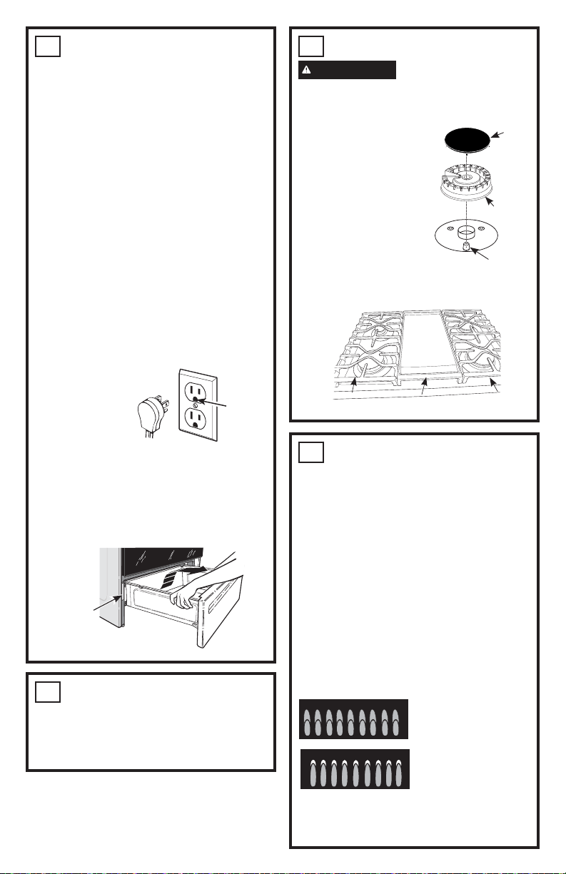
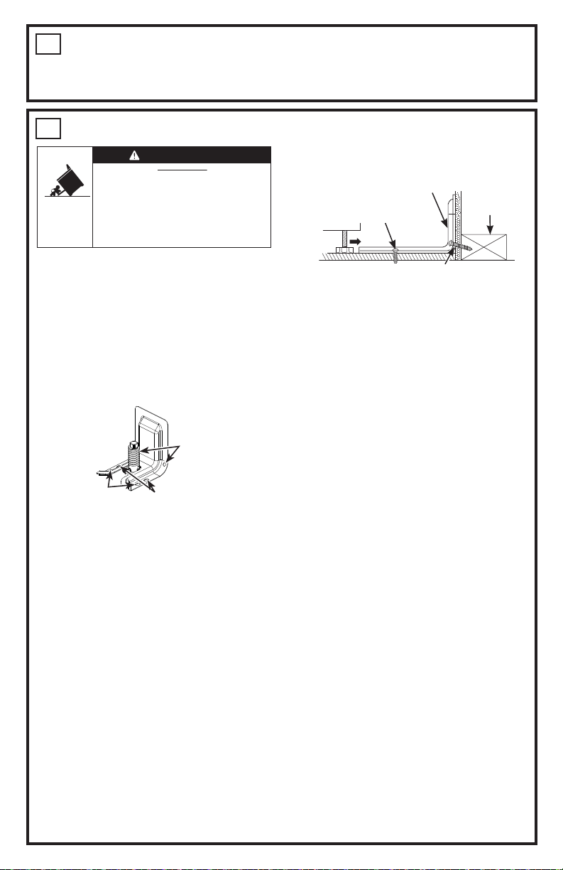
INSTRUCCIONES DE INSTALACIÓN
31-2001195 Rev. 1 09-23 GEA
9
INSTALACIÓN DE DISPOSITIVO ANTI-VOLCADURAS
3DUDUHGXFLUHOULHVJRGHYROFDUODFRFLQD
ésta debe sujetarse mediante un soporte anti-
YROFDGXUDVFRQXQDDGHFXDGDLQVWDODFLyQ
5HWLUHFXDOTXLHUVRSRUWHDQWLYROFDGXUDV
DFWXDOPHQWHXVDGR\UHDOLFHODLQVWDODFLyQFRQ
HOVRSRUWHDQWLYROFDGXUDVSURYLVWR
1. IMPORTANTE: 'HWHUPLQHODXELFDFLyQILQDO
de la cocina antes de tratar de instalar el
VRSRUWH5HWLUHHOVRSRUWHDQWLYROFDGXUDV
GHOHVSDFLRGHLQVWDODFLyQHQFDVRGHHVWDU
SUHVHQWHIURPLQVWDOOVSDFHLISUHVHQW
a. Coloque el soporte en el piso con el lado
trasero sobre la pared trasera. Si la
FRFLQDQROOHJDDODSDUHGWUDVHUDDOLQHH
el lado trasero del soporte con el panel
WUDVHURGHODFRFLQDHQVXXELFDFLyQILQDO
6LHOVRSRUWHQRWRFDODSDUHGWUDVHUD
XVWHG'(%(DWRUQLOODUHOVRSRUWHDO3,62
FRPRVHGHVFULEHHQHO3DVR
b. Coloque el lado del soporte sobre el
JDELQHWHL]TXLHUGRRGHUHFKR6LQR
KD\XQJDELQHWHDG\DFHQWHDOLQHHHO
H[WUHPRGHOVRSRUWHFRQHOSDQHOODWHUDO
GHODFRFLQDHQVXXELFDFLyQILQDO6L
el mostrador de encimera sobresale
GHOJDELQHWHPRGLILTXHODSRVLFLyQGHO
soporte desde el gabinete considerando la
cantidad que sobresale.
F0DUTXHODXELFDFLyQSDUDHOSDUGH
RULILFLRVTXHVHXWLOL]DUiQYHUODLOXVWUDFLyQ
de arriba).
NOTA:3DUDLQVWDODFLRQHVGH3,62XWLOLFH
OD8ELF$R%3DUDODLQVWDODFLyQGH
3$5('75$6(5$XWLOLFHOD8ELF&
(OVRSRUWHGHEHDWRUQLOODUVHDO3,62RDOD
3$5('75$6(5$
Instalación de PISO:
PISO DE MADERA: Utilice los tornillos
SURYLVWRVSDUDVXMHWDUHOVRSRUWHXWLOL]DQGRHO
SDUGHRULILFLRVPDUFDGRV8ELF$R%
PISO DE CONCRETO: 8WLOL]DQGRXQDEURFD
SDUDFRQFUHWRSHUIRUHXQRULILFLRSLORWRGH
´GH´GHSURIXQGLGDGGHQWURGHOFRQFUHWR
en el centro de cada uno de los orificios
PDUFDGRV8ELF$R%8WLOLFHORVWRUQLOORV
SURYLVWRVSDUDVXMHWDUHOVRSRUWHDOSLVR
Instalación de PARED TRASERA:
8WLOLFHORVWRUQLOORVSURYLVWRVSDUDVXMHWDU
HOVRSRUWHXWLOL]DQGRHOSDUGHRULILFLRV
PDUFDGRVHQ8ELF&/RVWRUQLOORV'(%(1
ingresar en el umbral de madera. Si la pared
contiene parantes de metal o materiales
VLPLODUHVHQWRQFHVGHEHXVDUVHHOSLVR
Para controlar si el soporte es instalado y
DMXVWDGRGHIRUPDDSURSLDGDPLUHTXHGHEDMR
GHODFRFLQDODSDWDQLYHODGRUDWUDVHUDHVWp
DMXVWDGDDOVRSRUWH(QDOJXQRVPRGHORV
HOFDMyQGHDOPDFHQDPLHQWRRHOSDQHOGH
SURWHFFLyQVHSXHGHQUHWLUDUSDUDXQDIiFLO
LQVSHFFLyQ6LQRHVSRVLEOHUHDOL]DUXQD
LQVSHFFLyQYLVXDOGHVOLFHODFRFLQDKDFLD
DGHODQWHFRQILUPHTXHHOVRSRUWHDQWL
YROFDGXUDVHVWpDMXVWDGRGHIRUPDVHJXUDDO
SLVRRODSDUHG\GHVOLFHODFRFLQDKDFLDDWUiV
GHPRGRTXHODSDWDQLYHODGRUDWUDVHUDVH
HQFXHQWUHGHEDMRGHOVRSRUWHDQWLYROFDGXUDV
6LODHVWXIDHVUHWLUDGDSDUDVXOLPSLH]D
VHUYLFLRWpFQLFRRFXDOTXLHURWUDUD]yQ
DVHJ~UHVHGHTXHHOGLVSRVLWLYRDQWLYROFDGXUDV
YXHOYDDVHUFRORFDGRGHIRUPDFRUUHFWD
FXDQGRODHVWXIDVHDLQVWDODGDQXHYDPHQWH
6LQRVHWRPDHVWDSUHFDXFLyQVHSRGUiQ
producir caídas de la estufa y ocasionar la
PXHUWHRTXHPDGXUDVJUDYHVHQQLxRVR
DGXOWRV1XQFDUHWLUHFRPSOHWDPHQWHODV
SDWDVQLYHODGRUDV\DTXHODHVWXIDQRHVWDUi
DVHJXUDGDGHIRUPDDGHFXDGDDOGLVSRVLWLYR
DQWLYROFDGXUDV
8
CONTROLE LOS QUEMADORES PARA HONEAR Y ASAR
Ŷ&RQILJXUHODIXQFLyQ%DNH+RUQHDUHQ
)(OTXHPDGRUVHGHEHUiLOXPLQDUHQWUH
\VHJXQGRV
Ŷ&RQILJXUHDVDUHQ%URLO+L$VDGR$OWR/RV
modelos con quemadores a gas deberán
WDUGDUHQWUH\VHJXQGRVHQHQFHQGHUVH
11
LISTA DE CONTROL FINAL DE LA
INSTALACIÓN
Ŷ$VHJ~UHVHGHTXHODFLUFXODFLyQGHODFRPEXVWLyQ\HODLUHGHOD
YHQWLODFLyQDODHVWXIDHVWpQGHVREVWUXLGRV
Ŷ$VHJ~UHVHTXHWRGRVORVPDWHULDOHVGHHPSDTXH\FLQWDVVH
KD\DQUHWLUDGR(VWRLQFOX\HFLQWDVVREUHHOSDQHOPHWiOLFR
GHEDMRGHODVSHULOODVGHFRQWUROVLFRUUHVSRQGHFLQWD
DGKHVLYDFLQWDVGHDMXVWHFDUWyQ\SOiVWLFRSURWHFWRU6LHVWRV
PDWHULDOHVQRVHUHWLUDQVHSRGUiSURGXFLUFRPRUHVXOWDGRXQ
GDxRVREUHHOHOHFWURGRPpVWLFRXQDYH]TXHHOPLVPRKD\D
sido encendido y las superficies estén calientes.
Ŷ$VHJ~UHVHGHTXHWRGRVORVFRQWUROHVTXHGHQHQODSRVLFLyQGH
apagado.
Kit del
6RSRUWH$QWL
9ROFDGXUDV
,QFOXLGR
8ELF$
8ELF%
Ubic. C
Los tornillos deberán ingresar en el piso en la
8ELF$R%RHQODSDUHGHQOD8ELF&
Pared Trasera
(OWRUQLOORGHEHLQJUHVDUHQ
madera o concreto
6XMHFLyQDOSLVRRODSDUHGWUDVHUD
Umbral de
la pared
(OWRUQLOORGHEHLQJUHVDUen madera
Soporte
10
NIVELE LA ESTUFA
ADVERTENCIA
1XQFDUHWLUH
FRPSOHWDPHQWHODVSDWDVQLYHODGRUDV\D
que la cocina no estará asegurada de forma
DGHFXDGDDOGLVSRVLWLYRDQWLYROFDGXUDV
$(QFKXIHODXQLGDG
%0LGDODDOWXUDGHVXPRVWUDGRUGHHQFLPHUD
HQODSDUWHWUDVHUDGHODDEHUWXUD;
&$MXVWHODVSDWDVQLYHODGRUDVGHPRGRTXHOD
SDUWHWUDVHUDGHODSODFDGHFRFFLyQTXHGH
PiVDUULEDTXHODHQFLPHUD<
''HVOLFHODXQLGDGHQVXXELFDFLyQWHQLHQGR
FXLGDGRGHDGKHULUODVSDWDVQLYHODGRUDVHQ
HOGLVSRVLWLYRDQWLYROFDGXUDV
(2EVHUYHGHEDMRGHODXQLGDG\YHULILTXH
que la pata trasera esté completamente
DGKHULGDDOGLVSRVLWLYRDQWLYROFDGXUDV'H
QRVHUDVtUHWLUHODXQLGDG\DMXVWHODDOWXUD
de la pata trasera de modo que quede
correctamente adherida.
),QVWDOHORVHVWDQWHVHQHOKRUQR
*&RQWUROHODQLYHODFLyQFRORFDQGRXQQLYHOGH
burbuja de aire sobre uno de los estantes
GHOKRUQR+DJDGRVOHFWXUDV±FRQHO
QLYHOXELFDGRHQGLDJRQDOSULPHURHQXQD
GLUHFFLyQ\OXHJRHQODRWUD
+8VHXQDOODYHGHDMXVWHSDUDDMXVWDUODV
SDWDVQLYHODGRUDVIURQWDOHVKDVWDTXHOD
HVWXIDTXHGHQLYHODGD
,&RORTXHHOFDEOHGHPRGRTXHQRLQWHUILHUD
FRQHOFDMyQ
-9XHOYDDLQVWDODUHOFDMyQ3DUDDFFHGHU
DLQVWUXFFLRQHVFRQVXOWHHOPDQXDOGHO
propietario.
;
<
Placa de
&RFFLyQ
´R0iV
0HVDGD
1LYHOGH$JXD
/HYDQWH
la cocina
%DMHOD
cocina
• Un niño o adulto pueden volcar la cocina y morir.
• Instale el soporte anti-volcaduras provisto con
la unidad sobre la pared o el piso.
•
Asegúrese la estufa al soporte anti-volcaduras deslizando
la unidad hacia atras de tal manera que la pata niveladora
sea enganchada.
• Vuelva a adherir el soporte anti-volcaduras si la estufa
se mueve de lugar.
• Si esto no se hace, se podrá producir la muerte o
quemaduras graves en niños o adultos.
Riesgo de Caída
ADVERTENCIA
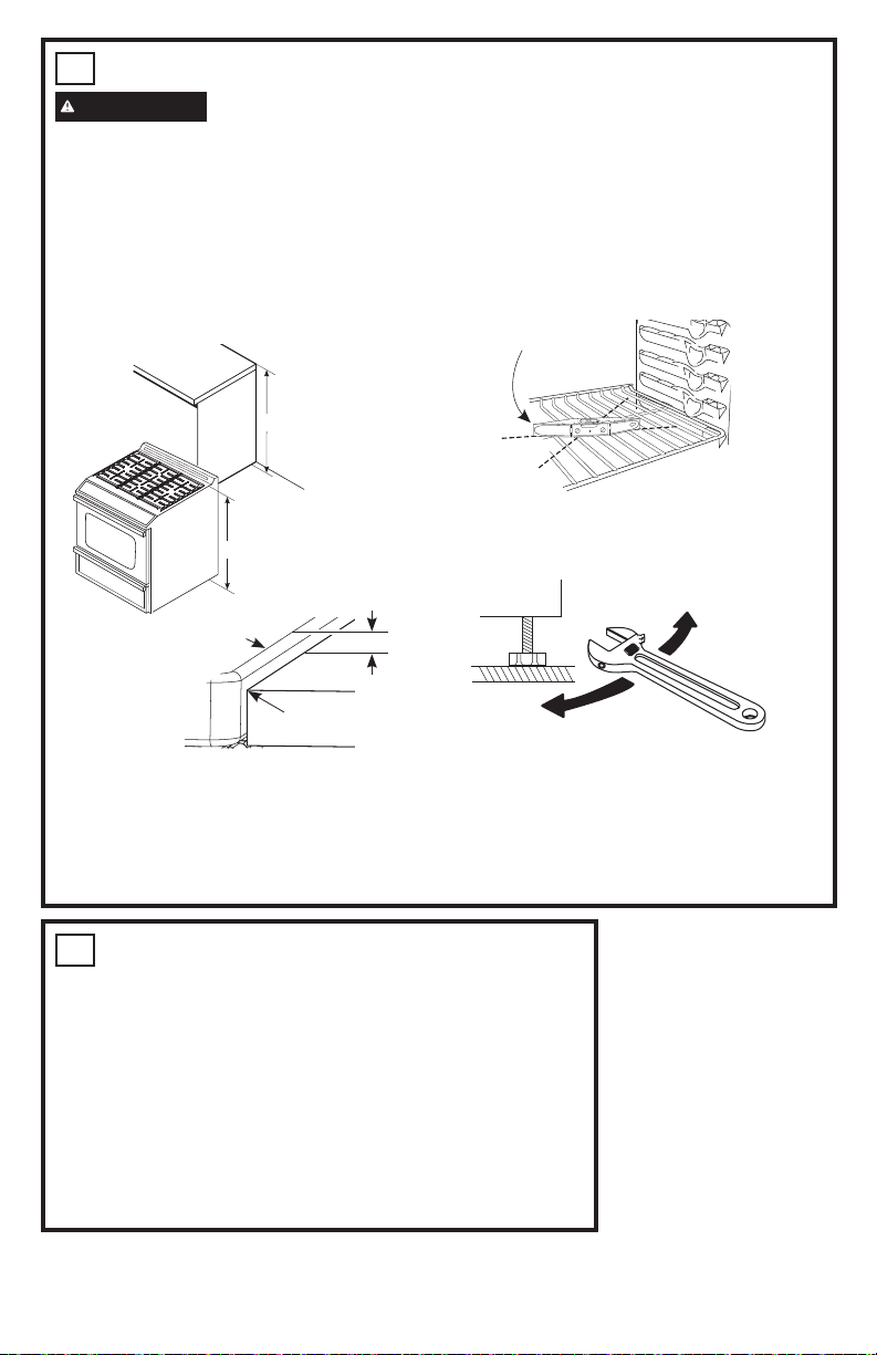