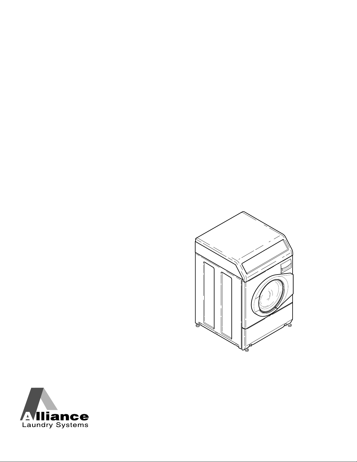
Installation/Operation
Frontload Washers
Metered Commercial
FLW1546C_SVG
Original Instructions
Keep These Instructions for Future Reference.
(If this machine changes ownership, this manual must accompany machine.)
www.alliancelaundry.com
Part No. 805988
December 2014

Front Matter
WARNING
Failure to install, maintain, and/or operate this ma-
chine according to the manufacturer's instructions
may result in conditions which can produce bodily
injury and/or property damage.
W030
WARNING
For your safety and to reduce the risk of fire or an
explosion, do not store or use gasoline or other
flammable vapors and liquids in the vicinity of this or
any other appliance.
W022
NOTE: The WARNING and IMPORTANT instructions ap-
pearing in this manual are not meant to cover all possi-
ble conditions and situations that may occur. It must
be understood that common sense, caution, and care-
fulness are factors which cannot be built into these
washers. These factors MUST BE supplied by the per-
son(s) installing, maintaining, or operating the washer.
Always contact the distributor, service agent, or the manufacturer
about any problems or conditions you do not understand.
Read all instructions before using washer.
This product uses FreeRTOS V7.2.0 (www.freertos.org).
Front Matter
Part No. 805988
©
Copyright, Alliance Laundry Systems LLC - DO NOT COPY or TRANSMIT 3

Table of Contents
Safety Information..................................................................................6
Explanation of Safety Messages....................................................................... 6
Important Safety Instructions........................................................................... 6
Dimensions and Specifications................................................................ 8
Installation........................................................................................... 10
Before You Start...........................................................................................10
Tools........................................................................................................10
Order of Installation Steps..........................................................................10
Position Unit Near Installation Area............................................................... 10
Remove Shipping Materials........................................................................... 10
Connect Fill Hoses........................................................................................11
Water Supply Requirements....................................................................... 11
Connecting Hoses......................................................................................12
Risers.......................................................................................................13
Non-Gravity Drain Models - Connect Drain Hose to Drain Receptacle.............. 13
Standpipe Installation................................................................................ 14
Position and Level the Washer....................................................................... 14
Wipe Out Inside of Wash Drum..................................................................... 15
Plug In the Washer........................................................................................15
Electrical Requirements............................................................................. 15
Earth/Ground Instructions.......................................................................... 16
Check Installation......................................................................................... 16
Operation............................................................................................. 17
Operation Instructions for MDC Washers........................................................17
Load Laundry........................................................................................... 17
Close Loading Door...................................................................................17
Add Laundry Supplies............................................................................... 17
Set Fabric Selector and Wash Temperature.................................................. 18
Start Washer............................................................................................. 18
Indicator Lights.........................................................................................18
Maintenance......................................................................................... 19
User-Maintenance Instructions....................................................................... 19
Lubrication............................................................................................... 19
Cold Weather Care.................................................................................... 19
Care of Your Washer................................................................................. 19
Cleaning Glass Sealing Area...................................................................... 19
©
Copyright 2014, Alliance Laundry Systems LLC
All rights reserved. No part of the contents of this book may be reproduced or transmitted in any form or by any means without the expressed
written consent of the publisher.
Part No. 805988
©
Copyright, Alliance Laundry Systems LLC - DO NOT COPY or TRANSMIT 4

Replacing Hoses........................................................................................19
Filter Screens............................................................................................ 19
Extended Non-Use.................................................................................... 19
Cleaning Foreign Object Trap.....................................................................19
Reinstallation of Shipping Materials............................................................19
Troubleshooting....................................................................................21
Contact Information............................................................................. 23
Installer Checklist.................................................................................24
Part No. 805988
©
Copyright, Alliance Laundry Systems LLC - DO NOT COPY or TRANSMIT 5
Safety Information
Explanation of Safety Messages
Precautionary statements (“DANGER,” “WARNING,” and
“CAUTION”), followed by specific instructions, are found in this
manual and on machine decals. These precautions are intended
for the personal safety of the operator, user, servicer, and those
maintaining the machine.
DANGER
Indicates an imminently hazardous situation that, if
not avoided, will cause severe personal injury or
death.
WARNING
Indicates a hazardous situation that, if not avoided,
could cause severe personal injury or death.
CAUTION
Indicates a hazardous situation that, if not avoided,
may cause minor or moderate personal injury or
property damage.
Additional precautionary statements (“IMPORTANT” and
“NOTE”) are followed by specific instructions.
IMPORTANT: The word “IMPORTANT” is used to in-
form the reader of specific procedures where minor
machine damage will occur if the procedure is not fol-
lowed.
NOTE: The word “NOTE” is used to communicate in-
stallation, operation, maintenance or servicing informa-
tion that is important but not hazard related.
Important Safety Instructions
Save These Instructions
WARNING
To reduce the risk of fire, electric shock, serious in-
jury or death to persons when using your washer,
follow these basic precautions:
W023
• Read all instructions before using the washer.
• Install the washer according to the INSTALLATION IN-
STRUCTIONS. Refer to the EARTH/GROUND INSTRUC-
TIONS in the INSTALLATION manual for the proper earth/
ground connection of the washer. All connections for water,
drain, electrical power and earth/ground must comply with lo-
cal codes and be made by licensed personnel when required.
Do not do it yourself.
• Do not install or store the washer where it will be exposed to
water and/or weather.
• Do not add the following substances or textiles containing
traces of the following substances to the wash water: gasoline,
kerosene, waxes, cooking oils, vegetable oils, machine oils,
dry-cleaning solvents, flammable chemicals, thinners or other
flammable or explosive substances. These substances give off
vapors that could ignite, explode or cause the fabric to catch
on fire by itself.
• Under certain conditions, hydrogen gas may be produced in a
hot water system that has not been used for two weeks or
more. HYDROGEN GAS IS EXPLOSIVE. If the hot water
system has not been used for such a period, before using a
washing machine or combination washer-dryer, turn on all hot
water faucets and let the water flow from each for several mi-
nutes. This will release any accumulated hydrogen gas. THE
GAS IS FLAMMABLE, DO NOT SMOKE OR USE AN
OPEN FLAME DURING THIS TIME.
• To reduce the risk of an electric shock or fire, DO NOT use
an extension cord or an adapter to connect the washer to the
electrical power source.
• Do not allow children to play on or in the washer. Close su-
pervision of children is necessary when the washer is used
near children. This appliance is not intended for use by per-
sons (including children) with reduced physical, sensory or
mental capabilities, or lack of experience and knowledge, un-
less they have been given supervision or instruction concern-
ing the use of the appliance by a person responsible for their
safety. This is a safety rule for all appliances.
• Cleaning and user maintenance shall not be made by children
without supervision.
• Children less than three years should be kept away unless
continuously supervised.
• Do not reach into the washer if the washtub or agitator, if ap-
plicable, is moving.
Safety Information
Part No. 805988
©
Copyright, Alliance Laundry Systems LLC - DO NOT COPY or TRANSMIT 6

• Never operate the washer with any guards, panels and/or parts
removed or broken. DO NOT tamper with the controls or by-
pass any safety devices.
• DO NOT operate individual units if they have been separated
from a stack unit.
• Use your washer only for its intended purpose, washing
clothes. Always follow the fabric care instructions supplied
by the garment manufacturer.
• Always read and follow manufacturer’s instructions on pack-
ages of laundry and cleaning aids. To reduce the risk of poi-
soning or chemical burns, keep them out of the reach of chil-
dren at all times (preferably in a locked cabinet). Heed all
warnings or precautions.
• Do not use fabric softeners or products to eliminate static un-
less recommended by the manufacturer of the fabric softener
or product.
• Loading door MUST BE CLOSED any time the washer is to
fill, tumble or spin. DO NOT bypass the loading door switch
by permitting the washer to operate with the loading door
open.
• Be sure water connections have a shut-off valve and that fill
hose connections are tight. CLOSE the shut-off valves at the
end of each wash day.
• Keep your washer in good condition. Bumping or dropping
the washer can damage safety features. If this occurs, have
your washer checked by a qualified service person.
• Do not repair or replace any part of the washer, or attempt any
servicing unless specifically recommended in the user-main-
tenance instructions or in published user-repair instructions
that you understand and have the skills to carry out. AL-
WAYS disconnect the washer from electrical supply before
attempting any service.
• Disconnect the power cord by grasping the plug, not the cord.
If the supply cord is damaged, it must be replaced by the man-
ufacturer, its service agent or similarly qualified persons in
order to avoid a hazard.
• Before the washer is removed from service or discarded, re-
move the lid or door to the washing compartment.
• Failure to install, maintain, and/or operate this washer accord-
ing to the manufacturer’s instructions may result in conditions
which can produce bodily injury and/or property damage.
NOTE: The WARNING and IMPORTANT SAFETY IN-
STRUCTIONS appearing in this manual are not meant
to cover all possible conditions and situations that may
occur. Common sense, caution and care must be exer-
cised when installing, maintaining, or operating the
washer.
Always contact your dealer, distributor, service agent or the man-
ufacturer about any problems or conditions you do not under-
stand.
Safety Information
Part No. 805988
©
Copyright, Alliance Laundry Systems LLC - DO NOT COPY or TRANSMIT 7
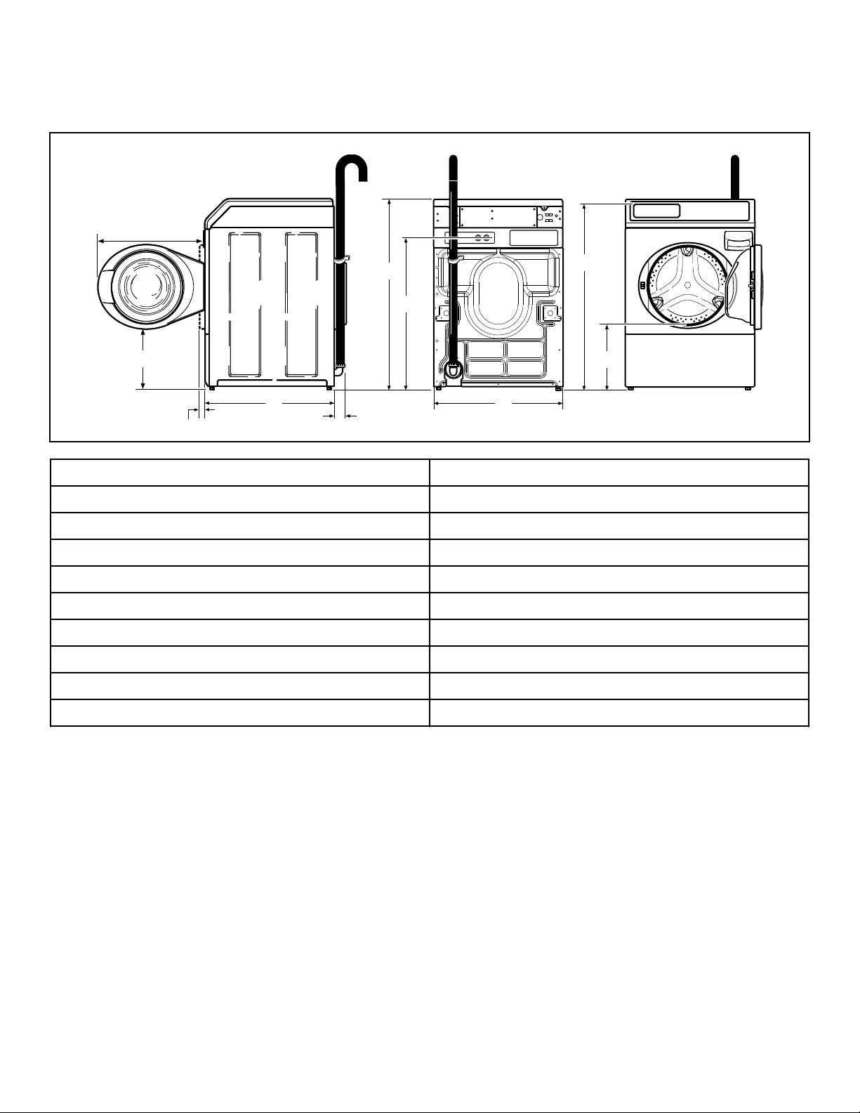
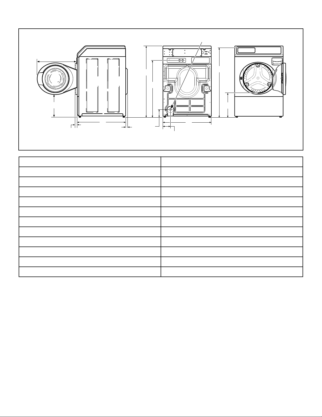
Dimensions and Specifications
Models Equipped With Drain Hose
FLW2382N_SVG
J
I
H
G
F
E
D
C
B
A
A 611 mm [24.06 in.]
B 1027 mm [40.42 in.]
C 813 mm [32 in.]
D 1006 mm [39.61 in.]
E 371 mm [14.6 in.]
F 683 mm [26.875 in.]
G 52 mm [2.04 in.]
H 704 mm [27.73 in.]
I 40 mm [1.59 in.]
J 333 mm [13.1 in.]
Dimensions and Specifications
Part No. 805988
©
Copyright, Alliance Laundry Systems LLC - DO NOT COPY or TRANSMIT 8
Models With Gravity Drain
FLW2383N_SVG
L
K
I
J
H
G
F
E
D
C
B
A
1
1. 38 mm [1.5 in.] Inside Diameter; 47 mm [1.86 in.] Outside Diameter
A 611 mm [24.06 in.]
B 1027 mm [40.42 in.]
C 813 mm [32 in.]
D 1006 mm [39.61 in.]
E 371 mm [14.6 in.]
F 683 mm [26.875 in.]
G 107 mm [4.2 in.]
H 104 mm [4.1 in.]
I 52 mm [2.04 in.]
J 704 mm [27.73 in.]
K 40 mm [1.59 in.]
L 333 mm [13.1 in.]
Dimensions and Specifications
Part No. 805988
©
Copyright, Alliance Laundry Systems LLC - DO NOT COPY or TRANSMIT 9
Installation
Before You Start
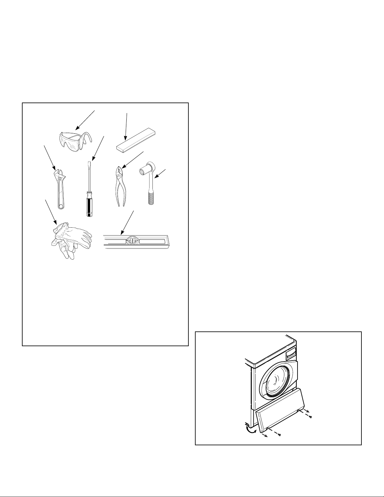
Tools
For most installations, the basic tools you will need are:
9
/
1
6
"
FLW2376N_SVG
5
6
7
8
4
3
2
1
1. Safety Glasses
2. Wood Block
3. Wrench
4. Screwdriver
5. Pliers
6. Socket Wrench
7. Gloves
8. Level
Figure 1
NOTE: An 20.32 cm [8 in.] coin drawer is required for
coin operated models.
NOTE: If the washer is delivered on a cold day (below
freezing), or is stored in an unheated room or area dur-
ing the cold months, do not attempt to operate it until
the washer has had a chance to warm up.
NOTE: Install dryer before washer. This allows room
for attaching exhaust duct.
NOTE: Some moisture in the wash drum is normal. Wa-
ter is used during testing at the manufacturer.
NOTE: This appliance is suitable for use in countries
having a warm, damp climate.
Order of Installation Steps
The proper order of steps must be followed to ensure correct in-
stallation. Refer to the list below when installing your unit.
1. Position washer near the installation area.
2. Remove the shipping materials.
3. Connect the fill hoses.
4. For non-gravity drain models, connect the drain hose to the
drain receptacle.
5. For gravity drain models, connect the drain outlet to the drain
system.
6. Position and level the washer.
7. Wipe out inside of the washer.
8. Plug in the washer.
9. Check installation.
Position Unit Near Installation Area
Move unit so that it is within 1.2 meters [4 feet] of the desired
area of installation.
NOTE: For best performance and to minimize vibration
or movement, install washer on a solid, sturdy and lev-
el floor. Some floors may need to be reinforced, espe-
cially on a second floor or over a basement. Do not in-
stall the washer on carpeting, soft tile or other weakly
supported structures.
Remove Shipping Materials
1. Remove two screws at bottom of front access panel. Rotate
bottom of panel out and remove panel.
FLW2378N_SVG
Figure 2
Installation
Part No. 805988
©
Copyright, Alliance Laundry Systems LLC - DO NOT COPY or TRANSMIT 10
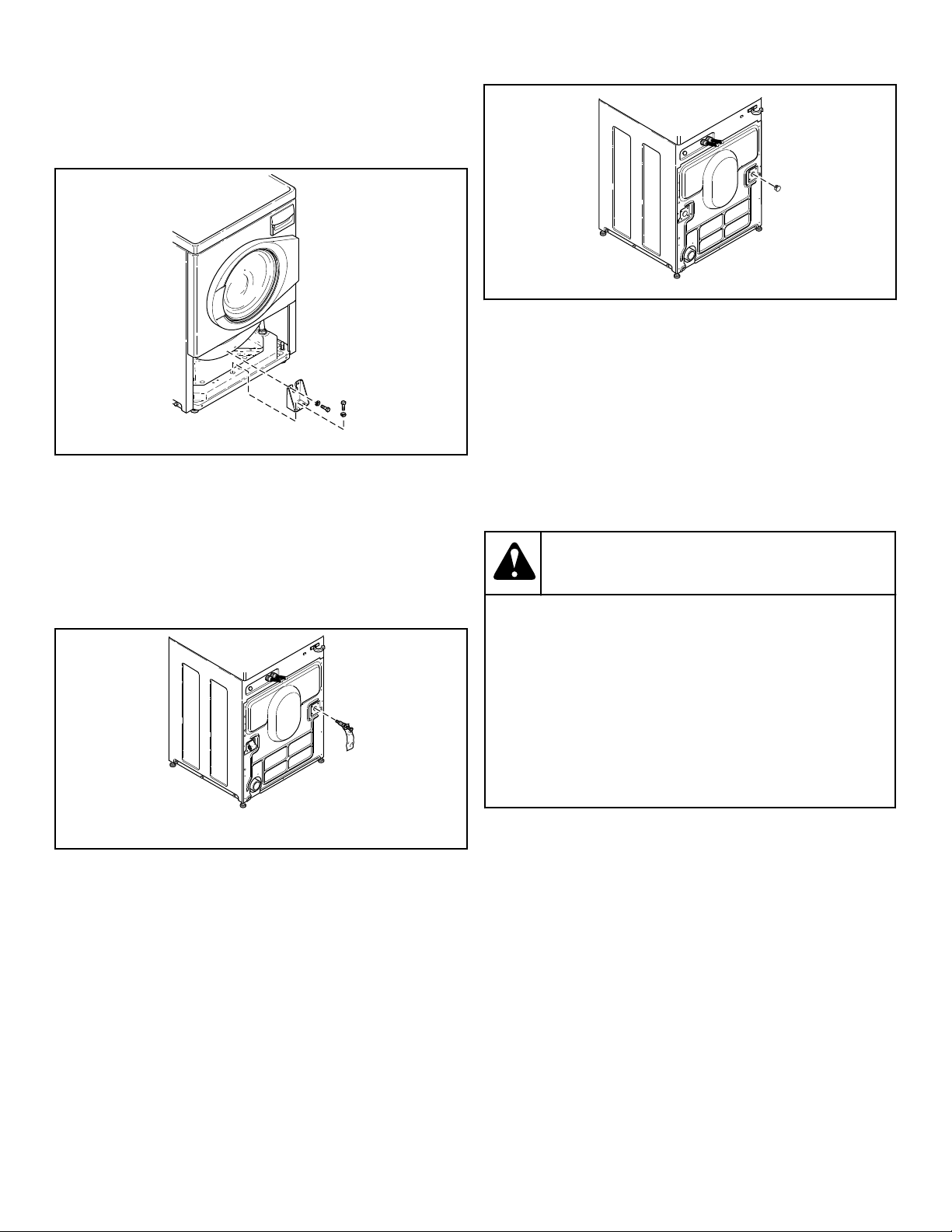
2. Remove two 9/16 inch bolts and washers holding shipping
brace to weight.
3. Remove two 9/16 inch bolts and washers holding shipping
brace to washer base and remove brace.
FLW2296N_SVG1
Figure 3
4. Go to rear of washer and pull label from rear shipping bolts.
5. Remove two 9/16 inch bolts. Unscrew each bolt while apply-
ing forward pressure just until bolt stops unthreading. Work
each bolt and spacer out by hand using a circular motion.
NOTE: Avoid backing bolts out completely or
spacers might fall into cabinet.
FLW2297N_SVG1
Figure 4
6. Insert two plugs included in accessories bag into rear shipping
bolt holes.
FLW2358N_SVG
Figure 5
7. Replace front access panel.
8. Save all shipping materials. They must be reinstalled any time
washer is moved more than four feet.
IMPORTANT: Do not lift or transport unit from front
or without shipping materials installed. Refer to the
Maintenace section for proper instructions on rein-
stalling the shipping materials.
Connect Fill Hoses
WARNING
Under certain conditions, hydrogen gas may be pro-
duced in a hot water system that has not been used
for two weeks or more. HYDROGEN GAS IS EXPLO-
SIVE. If the hot water system has not been used for
such a period and before using the washer, turn on
all hot water faucets and let the water flow from each
for several minutes. This will release any accumula-
ted hydrogen gas. The gas is flammable. Do not
smoke or use an open flame during this time.
W029
Water Supply Requirements
Water supply faucets must fit standard 19 mm [3/4 inch] female
garden hose couplings. DO NOT USE SLIP-ON OR CLAMP-
ON CONNECTIONS.
NOTE: Water supply faucets should be readily accessi-
ble to permit turning them off when washer is not being
used.
Recommended cold water temperature is 10° to 24° Celsius [50°
to 75° Fahrenheit]. Recommended maximum hot water tempera-
ture is 51° Celsius [125° Fahrenheit]. Warm water is a mixture of
hot and cold water. Warm water temperature is dependent upon
the water temperature and the pressure of both the hot and cold
water supply lines.
Installation
Part No. 805988
©
Copyright, Alliance Laundry Systems LLC - DO NOT COPY or TRANSMIT 11
WARNING
To prevent personal injury, avoid contact with inlet
water temperatures higher than 51° Celsius [125°
Fahrenheit] and hot surfaces.
W748
Maximum flow rate for all water temperatures is 9.46 liters per
minute [2.5 gallons per minute] ± 15%.
Water pressure must be a minimum of 138 to a maximum of 827
kPa [minimum of 20 to a maximum of 120 pounds per square
inch] static pressure measured at the faucet.
NOTE: Water pressure under 138 kPa [20 pounds per
square inch] will cause an extended fill time in the
washer and may not properly flush out the detergent
dispenser.
The appliance is to be connected to the water mains using new
hose-sets and the old hose-sets should not be reused.
Turn on the water supply faucets and flush the lines for approxi-
mately two minutes to remove any foreign materials that could
clog the screens in the water mixing valve. This is especially im-
portant when installing your washer in a newly constructed or
renovated building. Build-up may have occurred during construc-
tion.
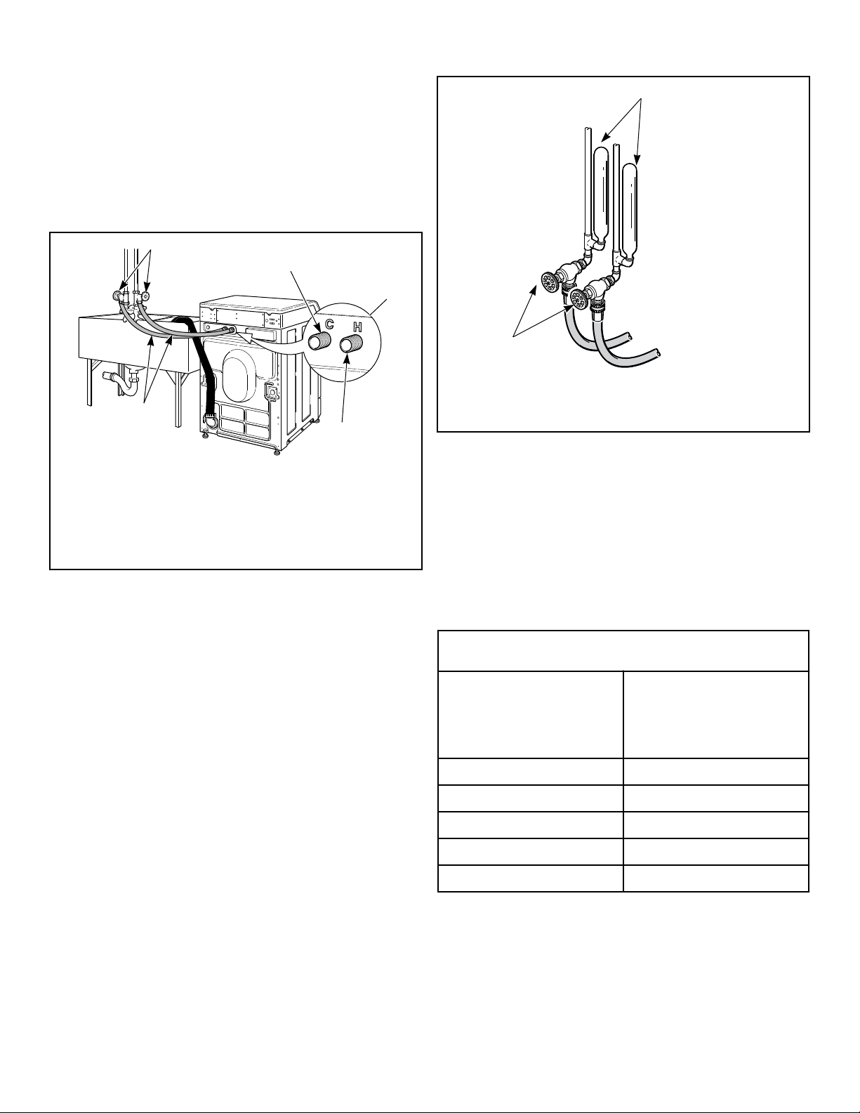
Connecting Hoses
To comply with Australian water regulations and Australian
standard AS/NZS3500.1, an approved dual check valve backflow
prevention device with the watermark is provided with the unit
and must be fitted at the point of connection(s) between the sup-
ply and the fitting. Refer to Figure 7 .
Figure 6
Connections should be supplied by a hot and a cold water line per
national and local codes and in accordance with AS/NZS 3500.1.
1. Insert rubber washers and filter screens (from accessories
bag) in water fill hose couplings (two hoses supplied with
washer). The filter screen must be facing outward.
NOTE: If using hoses with BSPP thread coupling, in-
sert filter screens into the BLACK colored hose cou-
plings and the rubber washers into the brass col-
ored hose couplings.
2. Connect fill hose couplings with filter screens to water supply
faucets.
3. Connect the other hose couplings to the hot and cold valve
connections at the rear of the washer.
NOTE: If using hoses with BSPP thread coupling,
connect the BLACK colored hose coupling end of
the fill hoses (with filter screens) to the water supply
faucets. Then connect end of hoses with the brass
colored hose couplings to the hot and cold water
mixing valve connections at rear of washer.
4. Thread hose couplings onto valve connections finger tight.
Then turn 1/4 turn with pliers.
IMPORTANT: DO NOT cross thread or overtighten
couplings. This will cause them to leak.
5. Turn water on and check for leaks.
6. If leaks are found, retighten the hose couplings.
7. Continue tightening and rechecking until no leaks are found.
FLW2216N_SVG
HOT
COLD
7
6
5
4
3
2
1
1. Faucet
2. Fill Hoses
3. Install this end of hose to valve connections at rear of
washer
4. Plain Rubber Washer
5. Install this end of hose to water supply faucet (Black col-
ored coupling for BSPP thread)
6. Filter Screens
7. Dual Check Valves
Figure 7
Installation
12
©
Copyright, Alliance Laundry Systems LLC - DO NOT COPY or TRANSMIT Part No. 805988
IMPORTANT:
Hoses and other natural rubber parts deteriorate after extended
use. Hoses may develop cracks, blisters or material wear from the
temperature and constant high pressure they are subjected to.
All hoses should be checked on a monthly basis for any visible
signs of deterioration. Any hose showing the signs of deteriora-
tion listed above should be replaced immediately. All hoses
should be replaced every five years.
FLW2385N_SVG
1
5
2
3
4
1. Water Supply Faucets
2. Cold Water Connection
3. Water Mixing Valve
4. Hot Water Connection
5. Fill Hoses
Figure 8
IMPORTANT: Turn off water supply faucets after check-
out and demonstration. Owner should turn off water
supply whenever there will be an extended period of
non-use.
NOTE: Longer fill hoses are available (as optional
equipment at extra cost) if the hoses (supplied with the
washer) are not long enough for the installation. Order
hoses as follows:
• No. 20617 Fill Hose: 2.44 m [8 feet] (2 standard thread hose
couplings)
• No. 20618 Fill Hose: 3.05 m [10 feet] (2 standard thread hose
couplings)
• No. 37380 Fill Hose: 2.44 m [8 feet] (1 standard thread, 1
BSPP thread hose coupling)
• No. 37381 Fill Hose: 3.05 m [10 feet] (1 standard thread, 1
BSPP thread hose coupling)
Risers
Risers (or air cushions) may have to be installed if the pipes
knock or pound when flow of water stops. The risers are more ef-
ficient when installed as close as possible to the water supply fau-
cets. Refer to Figure 9 .
W005I_SVG
2
1
1.
Risers (Air cushions)
2. Water Supply Faucets
Figure 9
Non-Gravity Drain Models - Connect
Drain Hose to Drain Receptacle
Remove the drain hose from its shipping position on the rear of
the washer by removing the shipping tape.
IMPORTANT: Drain receptacle must be capable of han-
dling a minimum of 35 mm [1-3/8 inch] outside diame-
ter drain hose.
Drain Flow Rate
Drain Height
Flow Rate
liters per minute [gal-
lons per minute]
0.9 m [3 ft.] 32.7 [8.6]
1.5 m [5 ft.] 25.9 [6.8]
1.8 m [6 ft.] 22.7 [6.0]
2.1 m [7 ft.] 19.5 [5.1]
2.4 m [8 ft.] 15.2 [4.0]
Installation
Part No. 805988
©
Copyright, Alliance Laundry Systems LLC - DO NOT COPY or TRANSMIT 13
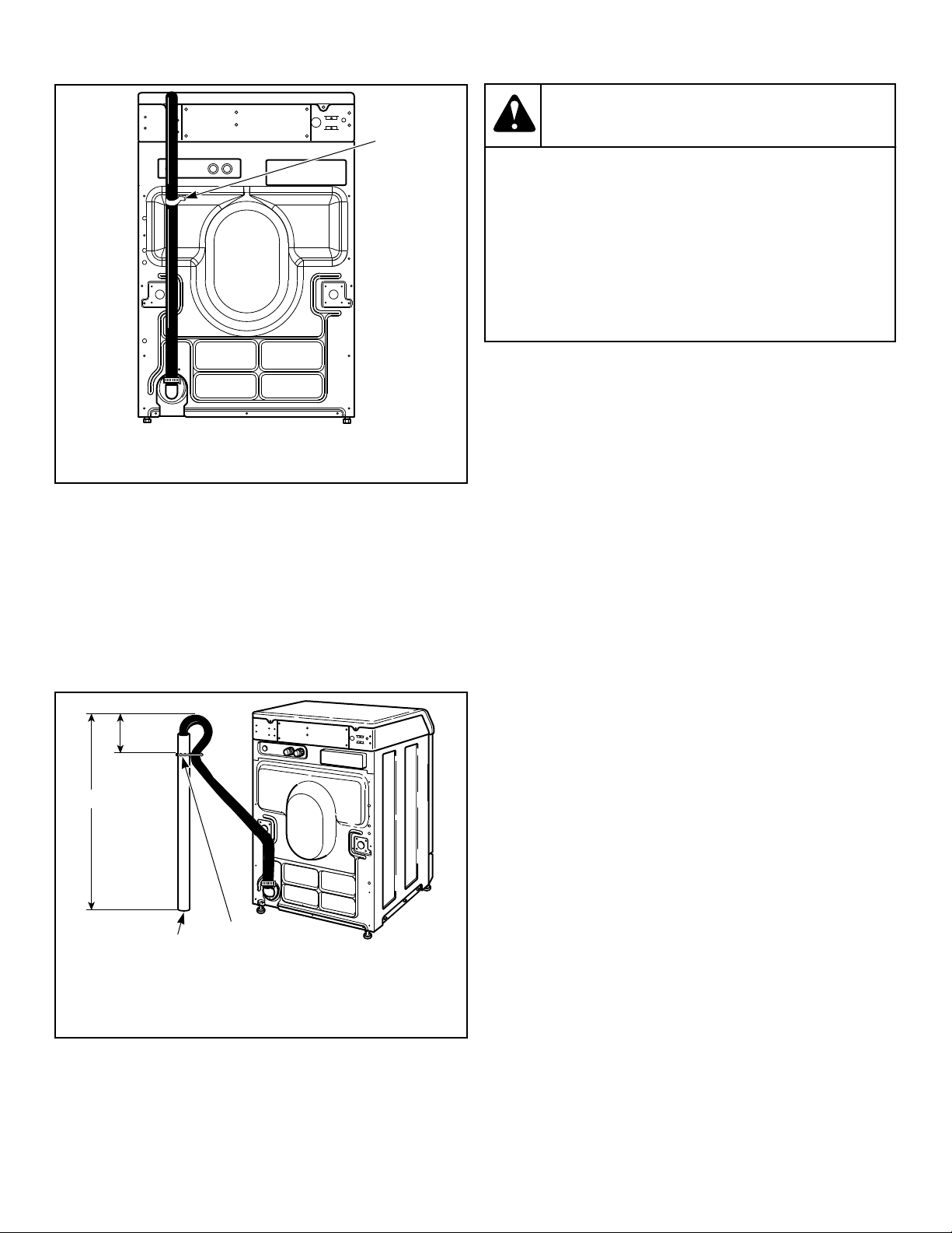
FLW2386N_SVG1
1
1. Shipping Tape
Figure 10
Standpipe Installation
1. Place the drain hose into the standpipe.
2. Remove the beaded tie-down strap from accessories bag and
place around standpipe and drain hose and tighten strap to
hold hose to standpipe. Refer to Figure 11 . This will prevent
the drain hose from dislodging from drain receptacle during
use.
FLW2387N_SVG
3
1
2
1. 610 to 914 mm [24 to 36 in.] Recommended Height
2. Beaded strap from accessory bag
3. Standpipe 51 mm [2 in.] or 40 mm [1-1/2 in.]
Figure 11
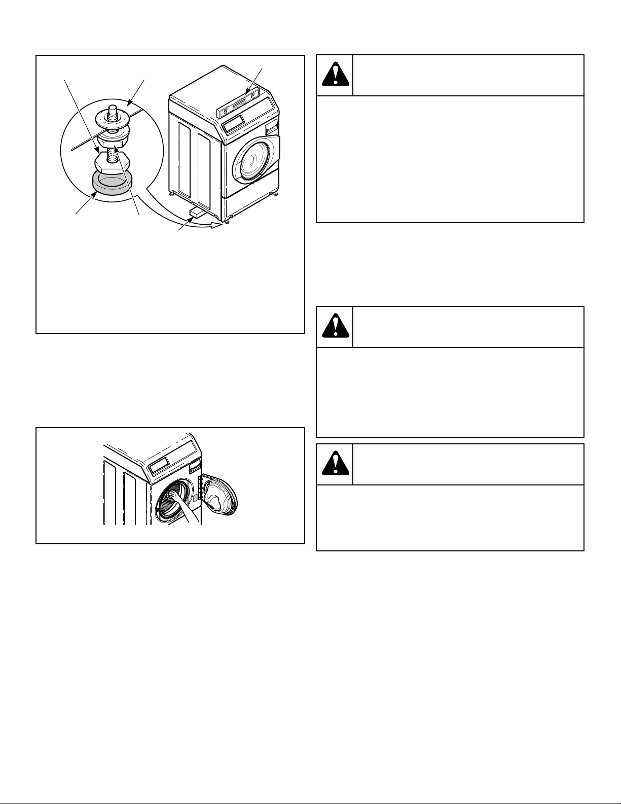
Position and Level the Washer
WARNING
Washers elevated above floor level must be anch-
ored to that elevated surface, base or platform. The
material used to elevate the washer should also be
anchored to the floor to ensure that the washer will
not walk or that the washer can not be physically
pulled, tipped or slid from its installed position. Fail-
ure to do so may result in conditions which can pro-
duce serious injury, death and/or property damage.
W306
1. Position unit so it has sufficient clearance for installation and
servicing.
NOTE: Use of the dispenser drawer or washer door
as a handle in the transportation of the washer may
cause damage to the dispenser or door.
2. Place unit in position on a solid, sturdy and level floor. Instal-
ling the unit on any type of carpeting, soft tile or other weakly
supported structures is not recommended.
3. Place a level on the raised portion of cabinet top and check if
the unit is level from side to side and front to back.
4. If unit is not level, tilt unit to access the front and rear level-
ing legs. For easier access to leveling legs, prop up unit with a
wooden block.
5. Loosen 7/8 in. locknut and adjust legs by screwing into or out
of unit base until the unit is level from side to side and front
to back (using a level). Unit should not rock.
NOTE: Leveling legs can also be adjusted from in-
side the unit using an adjustable wrench.
6. Tighten the locknuts securely against the unit base. If the
locknuts are not tight, unit will move out of position during
operation.
NOTE: DO NOT slide unit across floor if the leveling
legs have been extended. Legs and base could be-
come damaged.
7. Remove rubber feet from accessories bag and place on all
four leveling legs.
8. Verify that unit doesn’t rock.
Installation
14
©
Copyright, Alliance Laundry Systems LLC - DO NOT COPY or TRANSMIT Part No. 805988
FLW2312N_SVG
1
2
3
4
5
6
1. Leveling Leg
2. Washer Base
3. Level
4. Wood Block
5. Locknut
6. Rubber Foot
Figure 12
Wipe Out Inside of Wash Drum
Prior to first wash, use an all purpose cleaner or a detergent
and water solution and a damp cloth to remove shipping dust
from inside of the washer.
FLW2316N_SVG
Figure 13
Plug In the Washer
Electrical Requirements
240 Volt/50 Hertz with 3-Prong Earth/Ground Plug
This appliance is to be supplied through a residual current device
(RCD) having a rated residual operating current not exceeding 30
mA.
NOTE: The wiring diagram is located in the control cab-
inet.
WARNING
To reduce the risk of fire, electric shock, serious in-
jury or death, all wiring and earth/ground connec-
tions MUST conform with the latest edition of the
AS/NZS 2040.2:2005 and such local regulations as
might apply. It is the customer’s responsibility to
have the wiring, fuses and circuit breakers installed
by a qualified electrician to make sure adequate elec-
trical power is available to the washer.
W895
When plugging in the washer:
• DO NOT overload circuits.
• DO NOT use an extension cord.
• DO NOT use an adapter.
• DO NOT operate other appliances on the same circuit.
CAUTION
If this appliance is supplied from a cord extension
set or an electrical portable outlet device, the cord
extension set or electrical portable outlet device
must be positioned so that it is not subject to
splashing or ingress of moisture.
W563
WARNING
To reduce the risk of an electric shock or fire, DO
NOT use an extension cord or an adapter to connect
the washer to the electric power source.
W082
The washer is designed to be operated on a separate polarized
three-wire, earth/ground, 240 Volt, 50 Hertz, single-phase electri-
cal circuit protected by a 10 ampere fuse, equivalent fusetron or
circuit breaker.
The 3-prong earth/ground plug on the power cord should be plug-
ged directly into a polarized three-slot receptacle properly instal-
led and connected to a protective earth/ground and rated 240
Volts AC (alternating current) 10 Amps. Refer to Figure 14 to
determine correct polarity of the wall receptacle.
Installation
Part No. 805988
©
Copyright, Alliance Laundry Systems LLC - DO NOT COPY or TRANSMIT 15
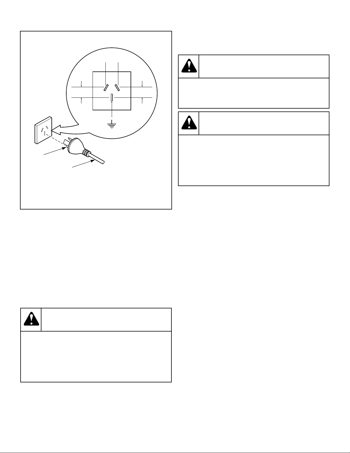
Standard 240 Volt, 50 Hertz, 3 Wire Effective Earth/
Ground Circuit
TLW2166N_SVG
2
1
43
3
1. Power Cord
2. Earth/Ground Prong
3. 240 Volt/50 Hertz
4. 0 Volt
Figure 14
Earth/Ground Instructions
This appliance must be properly connected to protective earth/
ground. In the event of malfunction or breakdown, the earth/
ground will reduce the risk of electric shock by providing a path
of least resistance for electric current.
The appliance is equipped with a cord having an equipment earth/
ground conductor and a three-prong earth/ground plug. The plug
must be plugged into an appropriate outlet that is properly instal-
led and connected to a protective earth/ground in accordance with
all local codes and ordinances.
WARNING
Improper connection of the equipment earth/ground
conductor can result in a risk of electric shock.
Check with a qualified electrician or service person if
you are in doubt as to whether the unit is properly
connected to a protective earth/ground.
W893
• DO NOT modify the plug provided with the unit – if it will
not fit the outlet, have a proper outlet installed by a qualified
electrician.
• If the laundry room’s electrical supply does not meet the
above specifications and/or if you are not sure the laundry
room has an effective earth/ground, have a qualified electri-
cian or your local electrical utility company check it and cor-
rect any problems.
WARNING
Any disassembly requiring the use of tools must be
performed by a suitably qualified service person.
W299
WARNING
This unit is equipped with a three-prong (earth/
ground) plug for your protection against shock haz-
ard and should be plugged directly into a protective
earth/ ground three-prong receptacle. Do not cut or
remove the earth/ground prong from this plug.
W823
If the supply cord is damaged, it must be replaced by the manu-
facturer, its service agent, or similarly qualified persons in order
to avoid a hazard.
Check Installation
1. Refer to Installer Checklist on the back cover of this manual
and make sure that unit is installed correctly.
2. Run washer with a test load to make sure it is operating prop-
erly and properly leveled.
a. Put about six pounds of laundry (four bath towels and
three jeans) into washer.
b. Close door.
c. Rapid advance to the final spin part of the cycle.
d. When washer spins at high speed, verify that it is stable.
e. If it is not, after cycle is complete, refer to Position and
Level the Washer to readjust leveling legs.
Installation
16
©
Copyright, Alliance Laundry Systems LLC - DO NOT COPY or TRANSMIT Part No. 805988
Operation
Operation Instructions for MDC Wash-
ers
IMPORTANT: Prior to first wash, use an all-purpose
cleaner, or a detergent and water solution, and a damp
cloth to remove shipping dust from inside of washer.
IMPORTANT: Remove all sharp objects from laundry to
avoid tears and rips to items during normal machine
operation.
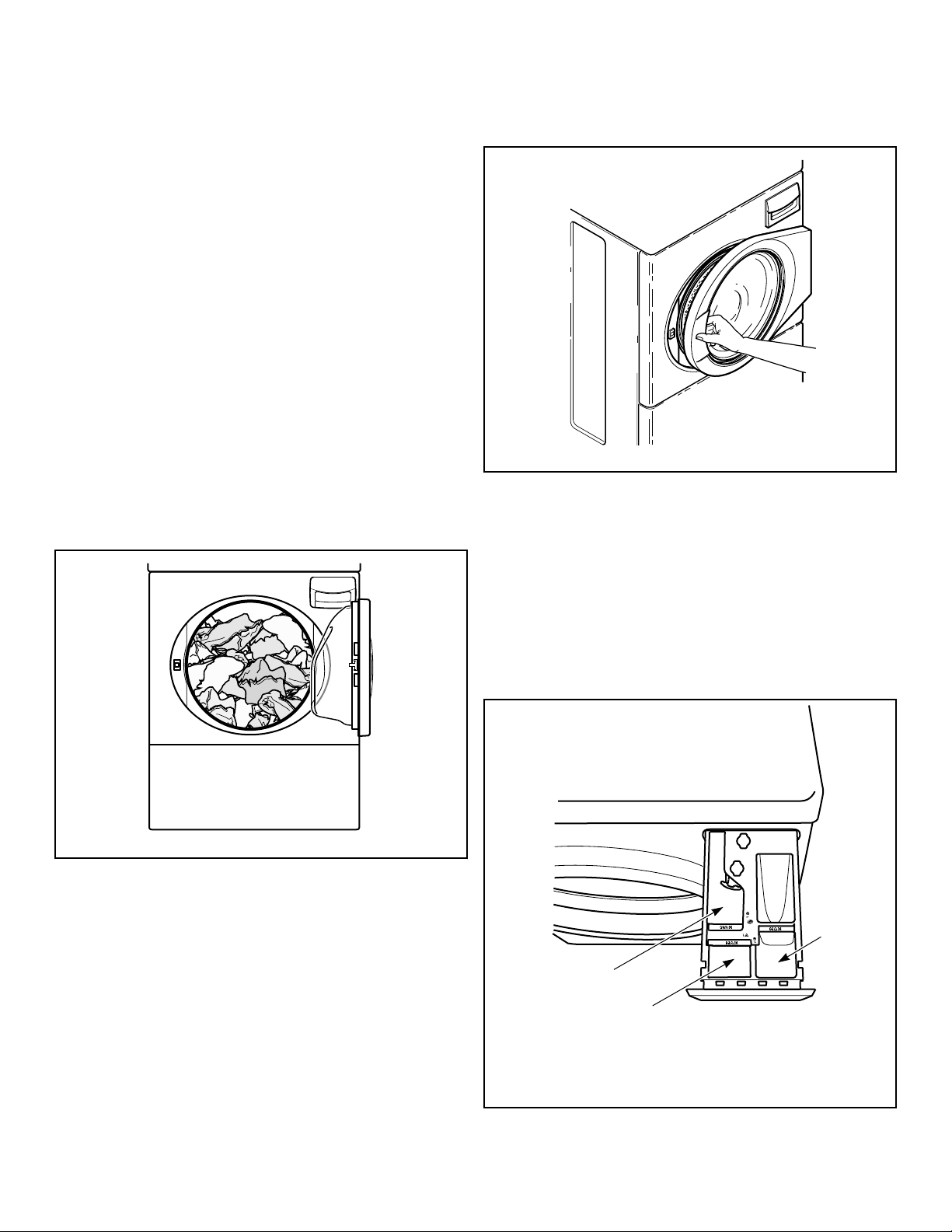
Load Laundry
1. Load items loosely into wash drum. Safety: 9.5 kg [21
pounds] maximum dry clothes load based on electrical safety
tests performed to Australia/New Zealand safety standard for
Washing Machines. Energy Efficiency: 10 kg [22 pounds] ca-
pacity.
NOTE: Small items such as baby socks may get
caught around the door. Place these articles inside
a mesh garment bag.
FLW2309N_SVG
Figure 15
2. When washing bulky items such as blankets and comforters,
use the DELICATE or DELICATES/COLD cycle. The cycle
includes agitation and final spin speeds that maintain the
load’s balance and minimize wear to the articles.
NOTE: Different fabrics will have different densities
and loads must be adjusted accordingly to meet ma-
chine loading specifications shown.
Close Loading Door
Close loading door tightly. The washer will not operate with
the loading door open.
FLW2310N_SVG
Figure 16
Add Laundry Supplies
1. Open dispenser drawer.
2. Measure and add low sudsing, high efficiency (HE) detergent
(1), bleach (2) and fabric softener (3) to the dispenser drawer.
IMPORTANT: If using non-HE detergent, avoid over-
sudsing by using 1/2 of the detergent manufactur-
er’s recommended amount.
3. Close dispenser drawer.
FLW2360N_SVG
E
H
R
S
O
F
T
W
E
A
N
S
LIQUID BLEACH
3
2
1
1. Detergent
2. Liquid Bleach
3. Fabric Softener
Figure 17
Operation
Part No. 805988
©
Copyright, Alliance Laundry Systems LLC - DO NOT COPY or TRANSMIT 17
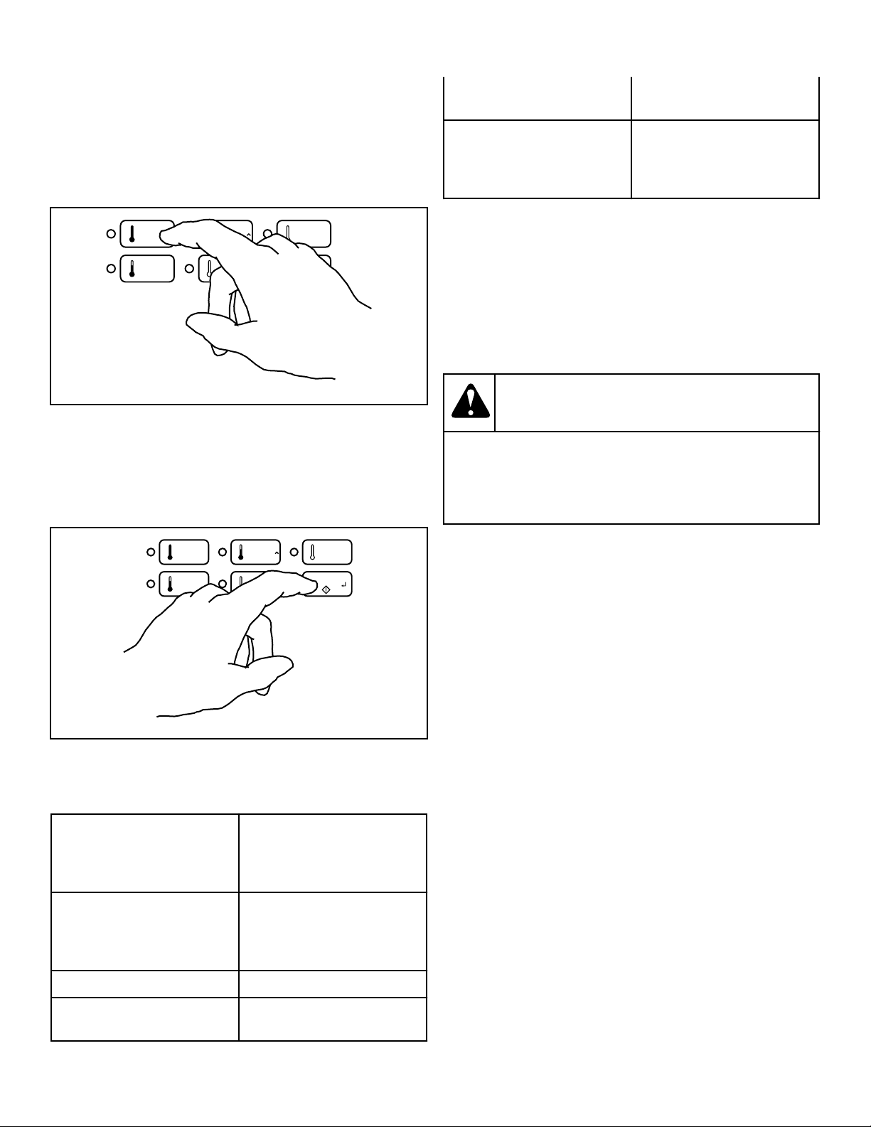
Set Fabric Selector and Wash Temperature
Push touchpad for NORMAL/HOT, NORMAL/WARM, NOR-
MAL/COLD, PERM PRESS/WARM or DELICATES/COLD
cycle. Light indicates selection.
NOTE: Changes can be made to Fabric Selector setting
up until the first fill is complete.
FLW2361N_SVG
NORMAL
HOT
PERM
PRESS
WARM
NORMAL
WARM
NORMAL
COLD
DELICATES
COLD
START
Figure 18
Start Washer
1. After vend price has been satisfied, push the START pad.
2. Door must be closed to start washer.
FLW2362N_SVG
NORMAL
HOT
PERM
PRESS
WARM
NORMAL
WARM
NORMAL
COLD
DELICATES
COLD
START
Figure 19
Indicator Lights
WASH WASH is lit at the beginning
of a wash cycle and will re-
main lit until the wash cycle is
complete.
RINSE RINSE is lit at the beginning
of all RINSE cycles and will
remain lit until the rinse cycle
is complete.
SPIN SPIN is lit for all spin cycles.
DOOR LOCKED DOOR LOCKED is lit when-
ever the door is locked. The
door cannot be opened when
this light is on.
START START flashes one second on
and one second off when the
full vend price has been satis-
fied.
IMPORTANT: If washer fails to operate properly after
installation, make sure electrical service and water
supply faucets are turned on. Are all the controls prop-
erly set? Have a qualified service person refer to the
wiring diagram (located inside of washer control cabi-
net) and check for broken, loose or incorrect wiring.
NOTE: Once a cycle has started, the door can only be
opened by first unplugging the power cord and waiting
one minute.
WARNING
To reduce the risk of bodily injury, do not remove
laundry from washer until all lights are out, and all
moving parts have stopped.
W092
Operation
18
©
Copyright, Alliance Laundry Systems LLC - DO NOT COPY or TRANSMIT Part No. 805988

Maintenance
User-Maintenance Instructions
Lubrication
All moving parts are sealed in a permanent supply of lubricant or
are equipped with oilless bearings. Additional lubrication will not
be necessary.
Do not lubricate the door hinge. If the hinge makes noise, replace
the hinge.
Cold Weather Care
If the unit is delivered on a cold day (below freezing), or is stored
in an unheated room or area during the cold months, do not at-
tempt to operate the washer until it has had a chance to warm up.
Water from the previous cycle may remain.
Care of Your Washer
Use only a damp or sudsy cloth for cleaning the control panel.
Some cleaning products may harm the finish on the control panel
or damage the interior. DO NOT use products that contain alco-
hol on the control panel. Wipe the panel dry after cleaning.
Wipe the washer cabinet as needed. If detergent, bleach or other
washing products are spilled on the cabinet, wipe immediately.
Some products will cause permanent damage if spilled on the
cabinet.
Do not use scouring pads or abrasive cleansers.
The wash drum will need no particular care although it may need
rinsing or wiping after an unusual load has been washed.
The outside of the door window can be cleaned with household
window cleaner.
Leave the door and dispenser drawer open slightly when not in
use. This will help keep them dry and prevent musty smells.
Running an occasional rinse cycle with bleach will help to avoid
a musty smell in the wash drum.
Cleaning Glass Sealing Area
In order to assure that the door properly seals against water leaks,
the following surfaces should be wiped off periodically:
• The outside perimeter of the door glass where the seal con-
tacts the glass
• The front surface of the door seal lip
Usually a mild soap solution will work. If there is an extreme
build-up of minerals from a hard water supply, the surfaces may
need to be cleaned with a lime removal chemical.
Replacing Hoses
Hoses and other natural rubber parts deteriorate after extended
use. Hoses may develop cracks, blisters or material wear from the
temperature and constant high pressure they are subjected to.
All hoses should be checked on a monthly basis for any visible
signs of deterioration. Any hose showing the signs of deteriora-
tion listed above should be replaced immediately. All hoses
should be replaced every five years.
Filter Screens
Check the filter screens in the fill hoses for debris or damage ev-
ery six months. Clean or replace them if necessary.
If the washer is filling with water slower than normal, check the
filter screens. Clean or replace them if necessary.
Order filter screen Part No. 803615 from the nearest authorized
parts distributor.
Extended Non-Use
IMPORTANT: To avoid possible property damage due
to flooding, turn off the water supply to the washer
whenever there will be an extended period of non-use.
Leave the loading door and dispenser drawer open during exten-
ded periods of non-use to allow the wash drum and drawer to dry
out and avoid a musty smell.
Cleaning Foreign Object Trap
The washer’s pump has a trap that may collect foreign objects.
The trap may need to be cleaned if water is draining slower than
usual. To clean:
1. Disconnect washer from electrical supply.
2. Remove two screws at bottom of the front access panel.
3. Rotate bottom of panel out and remove panel.
NOTE: The pump may have some water in it. Use a
rag or a container to catch water. If the wash drum
is full of water, use a wet/dry shop vacuum to catch
the water.
4. With rag or vacuum ready, unscrew the cap on the left side of
the pump and remove trap.
5. Clean the debris from the trap.
6. Reinstall the trap and access panel.
7. Reconnect washer to electrical supply.
Reinstallation of Shipping Materials
To prevent damage while moving the unit, the shipping materials
MUST be reinstalled.
Maintenance
Part No. 805988
©
Copyright, Alliance Laundry Systems LLC - DO NOT COPY or TRANSMIT 19
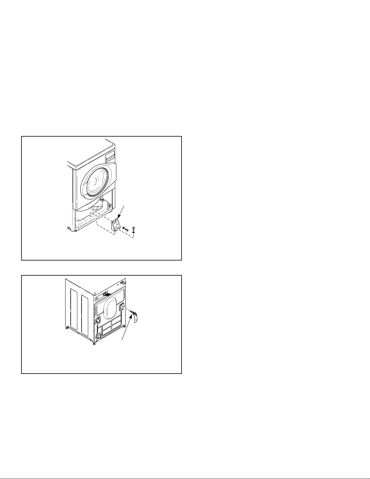
1. Disconnect washer from electrical supply.
2. Remove two screws at bottom of front access panel.
3. Rotate bottom of panel out and remove panel.
4. Attach shipping brace to weight and base using four bolts and
washers. Refer to Figure 20 .
5. Reinstall front access panel.
6. Go to rear of washer to install rear shipping bolt, washer,
spacer assemblies.
7. Insert shipping bolt assemblies into each shipping bolt hole.
Refer to Figure 21 .
8. Tighten bolt while pressing washer against rear panel to en-
sure spacer is fully inserted.
FLW2296N_SVG
1
1. Shipping Brace
Figure 20
FLW2297N_SVG
1
1. Shipping Bolt Assembly
Figure 21
Maintenance
20
©
Copyright, Alliance Laundry Systems LLC - DO NOT COPY or TRANSMIT Part No. 805988

Troubleshooting
Try these troubleshooting tips before making a service call. They
may save you time and money.
Washer Symptom Possible Cause/Solution
Won’t Fill • Make sure power cord is plugged all the way into the electrical outlet.
• Check the laundry room fuse or circuit breaker.
• Make sure that the controls are properly set.
• Press START keypad.
• Make sure that the loading door is closed tightly.
• Make sure hot and cold water faucets are turned on.
• Make sure that the fill hoses are not kinked or twisted.
• Clean the screens in the water mixing valve and the filter screens located at the faucet
end of the fill hoses.
Won’t Start • Make sure power cord is plugged all the way into the electrical outlet.
• Check the laundry room fuse or circuit breaker.
• Make sure that the controls are properly set.
• Press START keypad.
• Make sure that the loading door is closed tightly.
• Insert coin(s) or card. (metered models only)
• Make sure door latch is properly adjusted relative to door lock.
Won’t Spin/Tumble • Make sure power cord is plugged all the way into the electrical outlet.
• Check the laundry room fuse or circuit breaker.
• Make sure that the controls are properly set.
• Press START keypad.
• Make sure that the loading door is closed tightly.
• Broken drive belt. Call the service person.
• Foreign object trap in pump may be clogged. Clean the trap. Refer to Maintenance
section.
Stops/Pauses During Cycle • Pauses are part of the washer’s normal operation.
• Check the laundry room fuse or circuit breaker.
• Wash load may be unbalanced. Washer will stop and then restart spin automatically.
Won’t Drain • Make sure drain hose is not kinked or twisted.
• Make sure drain hose is not clogged.
• Make sure drain receptacle is not clogged.
• Refer to the Installation instructions to make sure that the drain hose has been proper-
ly installed.
• Foreign object trap in pump may be clogged. Clean the trap. Refer to Maintenance
section.
Troubleshooting
Part No. 805988
©
Copyright, Alliance Laundry Systems LLC - DO NOT COPY or TRANSMIT 21

Washer Symptom Possible Cause/Solution
Water Leaks • Check that fill hoses are properly installed on the faucets and the washer’s water mix-
ing valve.
• Check the condition of the fill hoses. Replace fill hoses every five years.
• Make sure drain receptacle is not clogged.
• Check laundry room plumbing.
• Check the condition of the rubber door gasket for tears or holes.
• Laundry load may be oversudsing. Make sure you are using low-sudsing, high effi-
ciency (HE) detergent.
• Laundry load may be overloaded. Make sure you are using proper load sizes.
• Make sure outside perimeter of the door glass where seal contacts glass is clean.
Too Many Soap Suds • Laundry load may be oversudsing. Make sure you are using low-sudsing, high effi-
ciency (HE) detergent.
• Make sure you are using the amount of detergent recommended on the detergent’s la-
bel. If using non-HE detergent, use only 1/2 of the detergent manufacturer's recom-
mended amount.
• Laundry load may be overloaded. Make sure you are using proper load sizes.
Vibrates/Moves Slightly • Make sure washer is level. Uneven leveling can cause vibration.
• Make sure washer is installed on a solid, sturdy and level floor. The washer should
not be installed on carpeting, soft tile, a platform or other weakly supported structures.
• Make sure rubber feet are installed on all four leveling legs. Refer to Position and
Level the washer.
Is Noisy • Make sure washer is level. Uneven leveling can cause vibration.
• Some sounds may be a part of normal operation for a frontload washer, such as click-
ing noise when door locks and clicking noise from balance ring during agitate part of
cycle.
Load is too Wet • Wash load may be unbalanced. The washer may have limited the spin speed to pre-
vent damage to the machine. Redistribute the load.
• Load is too small. Add items to make full load.
Wrong Water Temperature • Make sure that the controls are properly set.
• Check fill hoses. Make sure hot faucet hose is connected to hot mixing valve (indica-
ted with “H” on the valve bracket) and cold faucet is connected to cold mixing valve
(indicated with “C” on the valve bracket).
• Make sure laundry room water heater is adjusted properly.
Troubleshooting
22
©
Copyright, Alliance Laundry Systems LLC - DO NOT COPY or TRANSMIT Part No. 805988
Contact Information
If service is required, contact the nearest Factory Authorized
Service Center.
If you are unable to locate an authorized service center or are un-
satisfied with the service performed on your unit, contact:
Alliance Laundry Systems
Shepard Street
P.O. Box 990
Ripon, WI 54971-0990
U.S.A.
www.alliancelaundry.com
Phone: +1 (920) 748-3121 Ripon, Wisconsin
+32 56 41 20 54 Wevelgem, Belgium
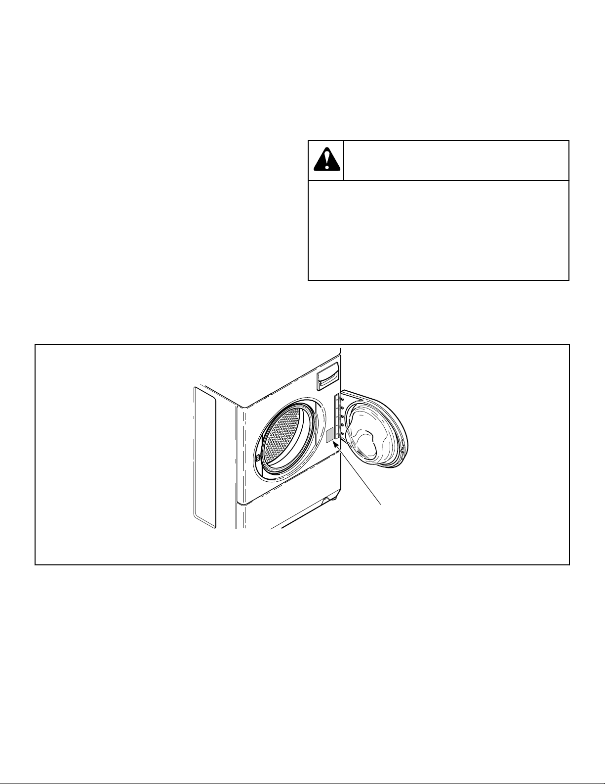
When calling or writing about your unit, PLEASE GIVE THE
MODEL AND SERIAL NUMBERS. The model and serial num-
bers are located on the serial plate. The serial plate will be in the
location shown in Figure 22 .
Date Purchased ______________________________
Model Number ______________________________
Serial Number _______________________________
Please include a copy of your bill of sale and any service receipts
you have.
WARNING
To reduce the risk of serious injury or death, DO
NOT repair or replace any part of the unit or attempt
any servicing unless specifically recommended in
the user-maintenance instructions or in published
user-repair instructions that you understand and
have the skills to carry out.
W329
If replacement parts are required, contact the source from where
you purchased your unit or call +1 (920) 748-3950 or +32 56 41
20 54 for the name and address of the nearest authorized parts
distributor.
FLW2305N_SVG
1
1. Serial Plate
Figure 22
Contact Information
Part No. 805988
©
Copyright, Alliance Laundry Systems LLC - DO NOT COPY or TRANSMIT 23
Installer Checklist
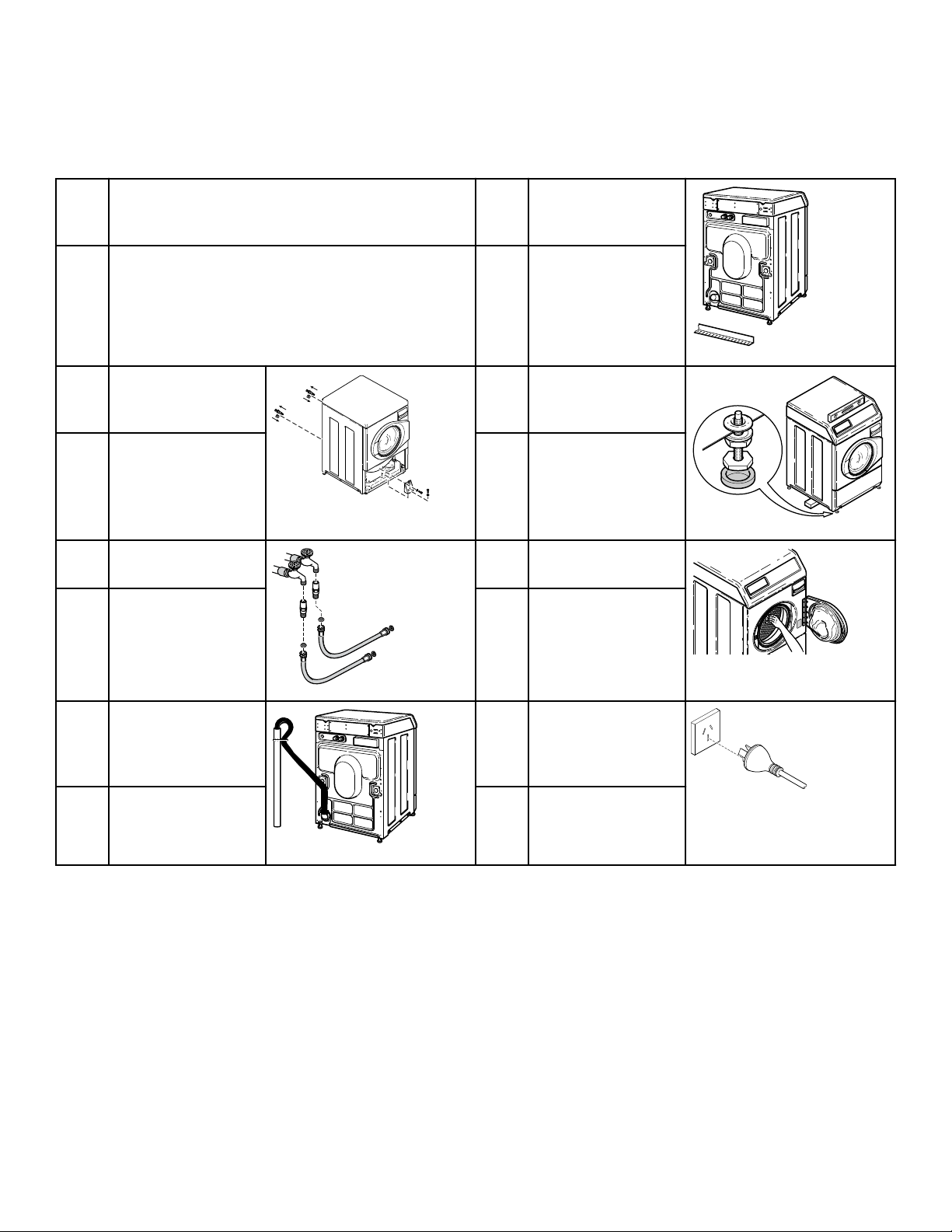
Fast Track for Installing the Washer
1 Position Washer Near Installation Area. 5 Gravity Drain Models -
Connect Drain Outlet
to Drain System.
FLW2388N_SVG1
CHECK CHECK
2 Remove the Shipping
Materials and Install
Plugs.
FLW2359N_SVG
6 Position and Level the
Washer.
FLW2312N_SVG1
CHECK CHECK
3 Connect Fill Hoses.
FLW2216N_SVG1
HOT
COLD
7 Wipe Out Inside of
Washer.
FLW2316N_SVG
CHECK CHECK
4 Non-Gravity Drain
Models - Connect
Drain Hose to Drain
Receptacle.
FLW2387N_SVG1
8 Plug In the Washer
TLW2170N_SVG
CHECK CHECK
Refer to the manual for more detailed information
Installer Checklist
Part No. 805988
©
Copyright, Alliance Laundry Systems LLC - DO NOT COPY or TRANSMIT 24