EnglishFrançaisEspañol
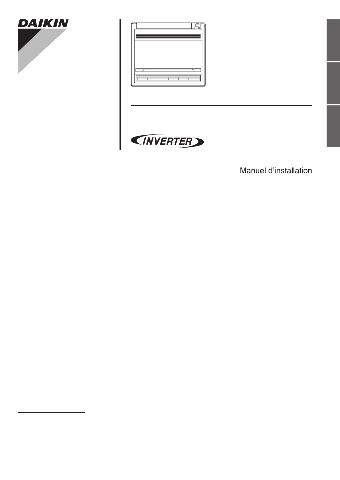
DAIKIN ROOM AIR CONDITIONER
INSTALLATION MANUAL
R410A Split Series
Installation manual
Manuel dinstallation
Manual de instalación
MODELS
FVXS09NVJU
FVXS12NVJU
FVXS15NVJU
FVXS18NVJU
Manuel dinstallation
00_CV_3P379970-7B.indd 1 10/28/2015 20:12:06
1 ■English
Safety Considerations
Contents
Safety Considerations .................................... 1
Accessories ..................................................... 3
Choosing an Installation Site ........................ 3
1. Indoor unit ................................................................... 3
2. Wireless remote controller ........................................... 3
Indoor Unit Installation Diagram ................... 4
Indoor Unit Installation ................................... 5
1. Refrigerant piping ........................................................ 5
2. Drilling a wall hole and installing wall embedded
pipe .............................................................................. 7
3. Drain piping ................................................................. 7
4. Installing indoor unit .................................................... 8
4-1. Preparation .......................................................... 8
4-2. Installation ........................................................... 9
5. Flaring the pipe end ..................................................... 12
6. Connecting the refrigerant pipe ................................... 12
6-1. Caution on piping handling .................................. 13
6-2. Selection of copper and heat insulation
materials .............................................................. 13
7. Checking for gas leakage ............................................ 13
8. Attaching the connection pipe ..................................... 13
9. Wiring .......................................................................... 14
10.When connecting to an HA system ............................. 15
11.How to set the different addresses .............................. 16
Trial Operation and Testing ............................ 17
1. Trial operation and testing ........................................... 17
2. Test items .................................................................... 17
Read these Safety Considerations for Installation carefully
before installing an air conditioner or heat pump. After completing
the installation, make sure that the unit operates properly during
the startup operation.
Instruct the user on how to operate and maintain the unit.
Inform users that they should store this installation manual with
the operation manual for future reference.
Always use a licensed installer or contractor to install this product.
Improper installation can result in water or refrigerant leakage,
electric shock, re, or explosion.
Meanings of DANGER, WARNING, CAUTION, and NOTE
Symbols:
DANGER
...........
Indicates an imminently hazardous
situation which, if not avoided, will
result in death or serious injury.
WARNING
.........
Indicates a potentially hazardous
situation which, if not avoided, could
result in death or serious injury.
CAUTION
..........
Indicates a potentially hazardous
situation which, if not avoided, may
result in minor or moderate injury.
It may also be used to alert against
unsafe practices.
NOTE
................
Indicates situations that may result
in equipment or property-damage
accidents only.
DANGER
• Refrigerant gas is heavier than air and replaces oxygen.
A massive leak can lead to oxygen depletion, especially
in basements, and an asphyxiation hazard could occur
leading to serious injury or death.
•
Do not ground units to water pipes, gas pipes, telephone
wires, or lightning rods as incomplete grounding can cause
a severe shock hazard resulting in severe injury or death.
Additionally, grounding to gas pipes could cause a gas leak
and potential explosion causing severe injury or death.
• If refrigerant gas leaks during installation, ventilate the
area immediately. Refrigerant gas may produce toxic gas
if it comes into contact with re. Exposure to this gas could
cause severe injury or death.
• After completing the installation work, check that the
refrigerant gas does not leak throughout the system.
• Do not install unit in an area where ammable materials
are present due to risk of explosions that can cause
serious injury or death.
• Safely dispose all packing and transportation materials
in accordance with federal/state/local laws or ordinances.
Packing materials such as nails and other metal or
wood parts, including plastic packing materials used for
transportation may cause injuries or death by suffocation.
WARNING
• Only qualied personnel must carry out the installation
work. Installation must be done in accordance with this
installation manual. Improper installation may result in
water leakage, electric shock, or re.
• When installing the unit in a small room, take measures
to keep the refrigerant concentration from exceeding
allowable safety limits. Excessive refrigerant leaks, in the
event of an accident in a closed ambient space, can lead
to oxygen deciency.
• Use only specied accessories and parts for installation
work. Failure to use specied parts may result in water
leakage, electric shock, re, or the unit falling.
• Install the air conditioner or heat pump on a foundation
strong enough that it can withstand the weight of the unit.
A foundation of insufcient strength may result in the unit
falling and causing injuries.
• Ta ke into account strong winds, typhoons, or earthquakes
when installing. Improper installation may result in the unit
falling and causing accidents.
01_EN_3P379970-7B.indd 1 11/12/2015 13:29:40
2■English
• Make sure that a separate power supply circuit is provided
for this unit and that all electrical work is carried out by
qualied personnel according to local, state, and national
regulations. An insufcient power supply capacity or
improper electrical construction may lead to electric shock
or re.
• Make sure that all wiring is secured, that specied wires
are used, and that no external forces act on the terminal
connections or wires. Improper connections or installation
may result in re.
• When wiring, position the wires so that the electrical
wiring box cover can be securely fastened. Improper
positioning of the electrical wiring box cover may result in
electric shock, re, or the terminals overheating.
• Before touching electrical parts, turn off the unit.
• It is recommended to install a ground fault circuit
interrupter if one is not already available. This helps
prevent electric shock or re.
•
Securely fasten the outdoor unit terminal cover (panel). If the
terminal cover/panel is not installed properly, dust or water
may enter the outdoor unit causing re or electric shock.
•
When installing or relocating the system, keep the refrigerant
circuit free from substances other than the specied
refrigerant (R410A) such as air. Any presence of air or other
foreign substance in the refrigerant circuit can cause an
abnormal pressure rise or rupture, resulting in injury.
• Do not change the setting of the protection devices. If the
pressure switch, thermal switch, or other protection device
is shorted and operated forcibly, or parts other than those
specied by Daikin are used, re or explosion may occur.
CAUTION
• Do not touch the switch with wet ngers. Touching a switch
with wet ngers can cause electric shock.
• Do not allow children to play on or around the unit to
prevent injury.
• The heat exchanger ns are sharp enough to cut. To avoid
injury wear gloves or cover the ns while working around
them.
• Do not touch the refrigerant pipes during and immediately
after operation as the refrigerant pipes may be hot or
cold, depending on the condition of the refrigerant owing
through the refrigerant piping, compressor, and other
refrigerant cycle parts. Your hands may suffer burns or
frostbite if you touch the refrigerant pipes. To avoid injury,
give the pipes time to return to normal temperature or, if
you must touch them, be sure to wear proper gloves.
• Install drain piping to proper drainage. Improper drain
piping may result in water leakage and property damage.
• Insulate piping to prevent condensation.
• Be careful when transporting the product.
• Do not turn off the power immediately after stopping
operation. Always wait for at least 5 minutes before turning
off the power. Otherwise, water leakage may occur.
• Do not use a charging cylinder. Using a charging cylinder
may cause the refrigerant to deteriorate.
• Refrigerant R410A in the system must be kept clean, dry,
and tight.
(a) Clean and Dry -- Foreign materials (including mineral
oils such as SUNISO oil or moisture) should be
prevented from getting into the system.
(b)
Tight -- R410A does not contain any chlorine, does not
destroy the ozone layer, and does not reduce the earth’s
protection again harmful ultraviolet radiation. R410A
can contribute to the greenhouse effect if it is released.
Therefore take proper measures to check for the tightness
of the refrigerant piping installation. Read the chapter
Refrigerant Piping Work and follow the procedures.
• Since R410A is a blend, the required additional refrigerant
must be charged in its liquid state. If the refrigerant is
charged in a state of gas, its composition can change and
the system will not work properly.
• The indoor unit is for R410A. See the catalog for indoor
models that can be connected. Normal operation is not
possible when connected to other units.
•
Remote controller (wireless kit) transmitting distance can be
shorter than expected in rooms with electronic uorescent
lamps (inverter or rapid start types). Install the indoor unit
far away from uorescent lamps as much as possible.
•
Indoor units are for indoor installation only. Outdoor units can be
installed either outdoors or indoors. This unit is for indoor use.
• Do not install the air conditioner or heat pump in the
following locations:
(a) Where a mineral oil mist or oil spray or vapor is
produced, for example, in a kitchen.
Plastic parts may deteriorate and fall off or result in
water leakage.
(b) Where corrosive gas, such as sulfurous acid gas, is
produced.
Corroding copper pipes or soldered parts may result in
refrigerant leakage.
(c) Near machinery emitting electromagnetic waves.
Electromagnetic waves may disturb the operation of
the control system and cause the unit to malfunction.
(d) Where ammable gas may leak, where there is carbon
ber, or ignitable dust suspension in the air, or where
volatile ammables such as thinner or gasoline are
handled. Operating the unit in such conditions can
cause a re.
• Ta ke adequate measures to prevent the outdoor unit
from being used as a shelter by small animals. Small
animals making contact with electrical parts can cause
malfunctions, smoke, or re. Instruct the user to keep the
area around the unit clean.
NOTE
• Install the power supply and inter-unit wires for the indoor
and outdoor units at least 3.5ft away from televisions or
radios to prevent image interference or noise. Depending
on the radio waves, a distance of 3.5ft may not be
sufcient to eliminate the noise.
• Dismantling the unit, treatment of the refrigerant, oil and
additional parts must be done in accordance with the
relevant local, state, and national regulations.
•
Do not use the following tools that are used with
conventional refrigerants: gauge manifold, charge hose, gas
leak detector, reverse ow check valve, refrigerant charge
base, vacuum gauge, or refrigerant recovery equipment.
• If the conventional refrigerant and refrigerator oil are
mixed in R410A, the refrigerant may deteriorate.
• This air conditioner or heat pump is an appliance that
should not be accessible to the general public.
• As design pressure is 478 psi, the wall thickness of eld-
installed pipes should be selected in accordance with the
relevant local, state, and national regulations.
English
01_EN_3P379970-7B.indd 2 11/12/2015 13:29:40
3 ■English
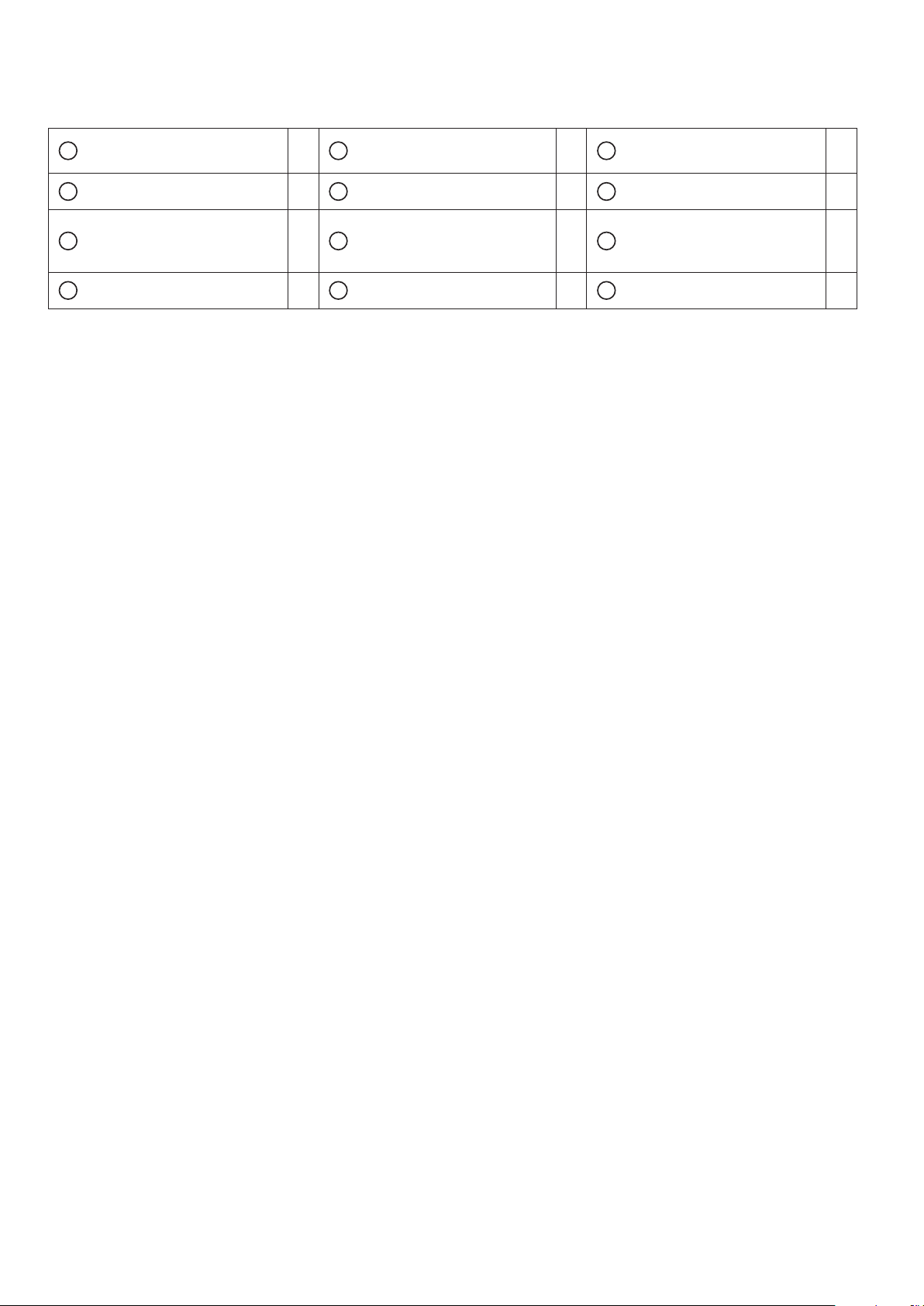
Accessories
A Mounting plate 1 B
Titanium apatite photocatalytic
air-purifying lter
2 C Drain hose 1
D Insulation tape 2 E Wireless remote controller 1 F Remote controller holder 1
G
Fixing screw for remote
controller holder 1/8” × 13/16”
(M3 × 20mm)
2 H
Indoor unit xing screw
3/16” × 1” (M4 × 25mm)
9 J
Dry battery AAA. LR03
(alkaline)
2
K Operation manual 1 L Installation manual 1 M Warranty 1
Choosing an Installation Site
• Before choosing the installation site, obtain user approval.
1. Indoor unit
The indoor unit should be positioned in a place where:
1) the restrictions on installation requirements specied in “Indoor Unit Installation Diagram” on page 4 are met,
2) both the air inlet and air outlet are unobstructed,
3) the unit is not exposed to direct sunlight,
4) the unit is away from the source of heat or steam,
5) there is no source of machine oil vapour (this may shorten the indoor unit service life),
6) cool/warm air is circulated throughout the room,
7) the unit is away from electronic ignition type uorescent lamps (inverter or rapid start type) as they may affect the remote
controller range,
8) the unit is at least 3.3ft (1m) away from any television or radio set (the unit may cause interference with the picture or
sound),
9) no laundry equipment is nearby.
2. Wireless remote controller
Turn on all the uorescent lamps in the room, if any, and nd a location where remote controller signals are properly
received by the indoor unit (within 23ft (7m)).
01_EN_3P379970-7B.indd 3 11/12/2015 13:29:40
4■English
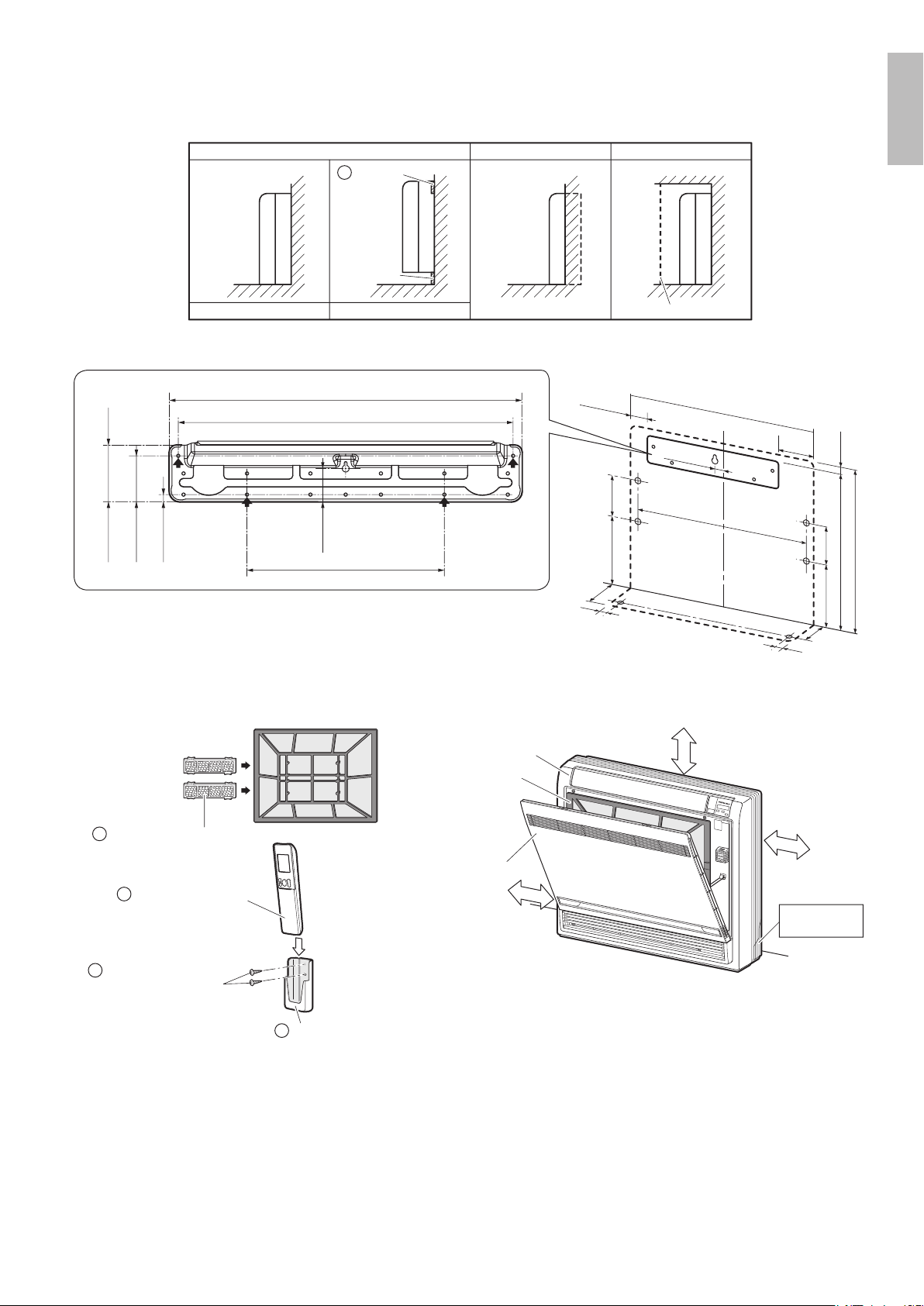
Indoor Unit Installation Diagram
• The indoor unit may be mounted in any of the 3 styles shown here.
Exposed Half concealed
Floor Installation Wall Installation
Concealed
Grid (field supply)
Mounting
plate
A
Molding
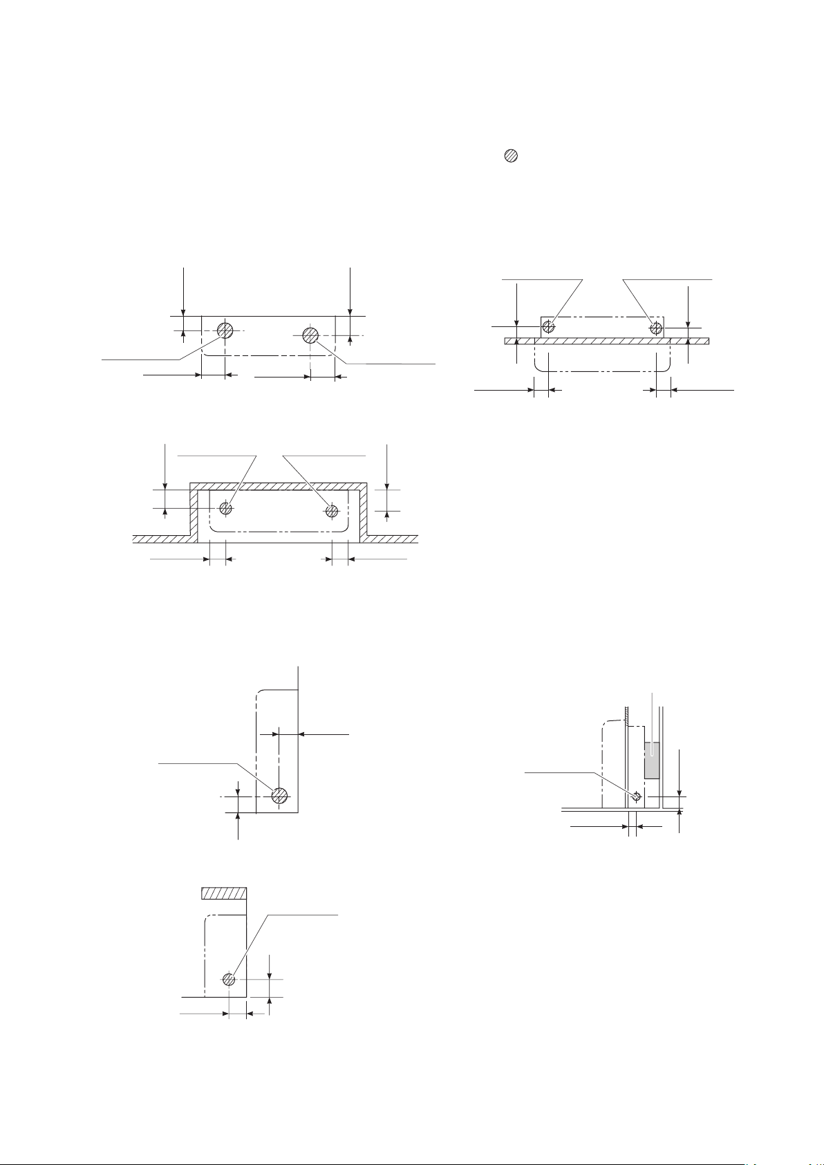
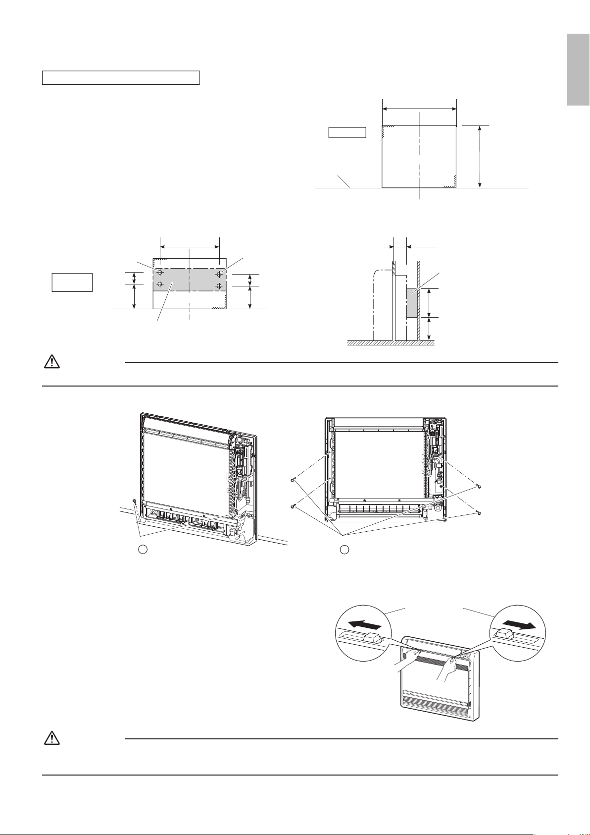
• Recommended mounting plate retention spots and dimensions.
unit: inch (mm)
(27-9/16 (700))
2-1/2 (64)
5-1/4
(134)
1 (26)
(23-5/8 (600))
22-5/8 (574)
5-1/2 (140)
9-13/16
(250)
5-7/8
(150)
9-1/16 (230)
25-3/8 (644)
8-1/4
(210)
6-5/16
(160)
1-3/8 (35)
1-3/8 (35)
1-3/8 (35)
18-11/16 (475)
19-11/16 (500)
3/8 (10)
2-9/16 (65)
3-1/8 (80)
11 (280)
1-7/8 (47)
Titanium apatite photocatalytic
air-purifying filter (2)
B
Front grille
Air filter
Front panel
1-15/16” (50mm)
or more from walls
2-3/4” (70mm) or more
1-15/16” (50mm)
or more from walls
Caulk pipe hole
gap with putty.
Fixing screw for
remote controller holder
1/8” × 13/16” (M3 × 20mm)
Remote controller holder
E
F
G
Wireless remote controller
English
01_EN_3P379970-7B.indd 4 11/12/2015 13:29:40
5 ■English
Indoor Unit Installation
1. Refrigerant piping
1) Drill a hole (φ2-9/16 inch (65mm) in diameter) in the spot indicated by the symbol in the illustration as below.
2) The location of the hole is different depending on which side of the pipe is taken out.
3) For piping, refer to “6. Connecting the refrigerant pipe” on page12.
4) Allow space around the pipe for a easier indoor unit pipe connection.
[Bottom piping]
1-3/4 (45)
2-3/8 (60)
2-15/16 (75)2-15/16 (75)
Left bottom piping
Right bottom piping
Wall
Left bottom piping Right bottom piping
2-15/16 (75)
1-15/16
(50)
1-3/8 (35)
Wall
2-15/16 (75)
Exposed installation Half concealed installation
Left bottom piping Right bottom piping
1-3/4 (45)
2-3/8 (60)
2-15/16 (75)2-15/16 (75)
unit: inch (mm)
Concealed installation
[Left/Right -side piping]
1-3/4
(45)
1-3/4 (45)
Left/right piping
Exposed installation Half concealed installation
Left/right piping
1-3/4
(45)
1-3/4 (45)
unit: inch (mm)
Concealed installation
1-3/4(45)
1-15/16 (50)
Wall
Left/right piping
Propping object
(field supply)
01_EN_3P379970-7B.indd 5 11/12/2015 13:29:41
6■English
[Back piping]
1-3/4
(45)
1-3/4
(45)
2-15/16 (75)2-15/16 (75)
Left back piping Right back piping
unit: inch (mm)
About the outdoor unit refrigerant pipe
• In order to connect the pipe, the outdoor unit refrigerant pipe must have a length of at least 13-3/4 inch (350mm)
measured from the wall.
13-3/4 (350) or more
2-15/16 (75)
1-3/4 (45)
Wall
Outdoor unit refrigerant pipe
Floor
unit: inch (mm)
CAUTION
Minimum allowable length
• The suggested shortest pipe length is 8.2ft (2.5m), in order to avoid noise from the outdoor unit and vibration.
(Mechanical noise and vibration may occur depending on how the unit is installed and the environment in which it is used.)
• Refer to the installation manual for the outdoor unit for the maximum pipe length.
• For multi-connections, refer to the installation manual for the multi outdoor unit.
English
01_EN_3P379970-7B.indd 6 11/12/2015 13:29:41

7 ■English
Indoor Unit Installation
2. Drilling a wall hole and installing wall embedded pipe
WARNING
For metal frame or metal board walls, be sure to use a wall embedded pipe and wall hole cover in the feed-through hole to
prevent possible heat, electric shock, or re.
• Be sure to caulk the gaps around the pipes with caulking material to prevent
condensation.
1) Drill a feed-through hole with a φ2-9/16 inch (65mm) diameter through the
wall at a downward angle toward the outside.
2) Insert a wall embedded pipe into the hole.
3) Insert a wall hole cover into wall pipe.
4) After completing refrigerant piping, wiring, and drain piping, caulk the pipe
hole gap with putty.
Inside
Outside
Caulking
(field supply)
Wall embedded
pipe
(field supply)
Wall hole cover
(field supply)
φ2-9/16”
(65mm)
3. Drain piping
• The drain pipe should be inclined downward so that water will ow smoothly
without any accumulation. (Should not be trap.)
No trap is permitted.
The drain pipe should
be inclined downward.
Do not put the end
of the hose in water.
• Use commercial rigid polyvinyl chloride pipe (general VP 20 pipe, outer diameter 1 inch (26mm), inner diameter 13/16
inch (20mm)) for the drain pipe.
• The drain hose (outer diameter φ11/16 inch (φ18mm) at connecting end, 8-11/16 inch (220mm) long) is supplied with the
indoor unit.
1) Perform drain piping work as outlined in the gure. (See Fig. 1)
• Insert the
C
drain hose into the socket of the drain pan. (See Fig. 2)
Fully insert the drain hose until it adheres to a seal of the socket.
2) Insulate the indoor drain pipe with 3/8 inch (10mm) or more of insulation material to prevent condensation.
3) Remove the air lters and pour some water into the drain pan to check the water ows smoothly.
1-15/16
(50) or more
8-11/16 (220)
5-7/8
(150)
3-15/16
(100)
3-15/16 (100)
Reducer
Vinyl chloride
drain pipe
(VP-30)
Vinyl chloride
drain pipe
(VP-20)
Drain hose
C
unit: inch (mm)
Insert drain hose
to this depth so
it won’t be pulled
out of drain pipe.
Drain
pan
Drain pan
Seal
Seal
Drain hose
C
Drain hose
C
Fig. 1 Fig. 2
CAUTION
Use polyvinyl chloride adhesive agent for gluing. Failure to do so may cause water leakage.
01_EN_3P379970-7B.indd 7 11/12/2015 13:29:43
8■English
4. Installing indoor unit
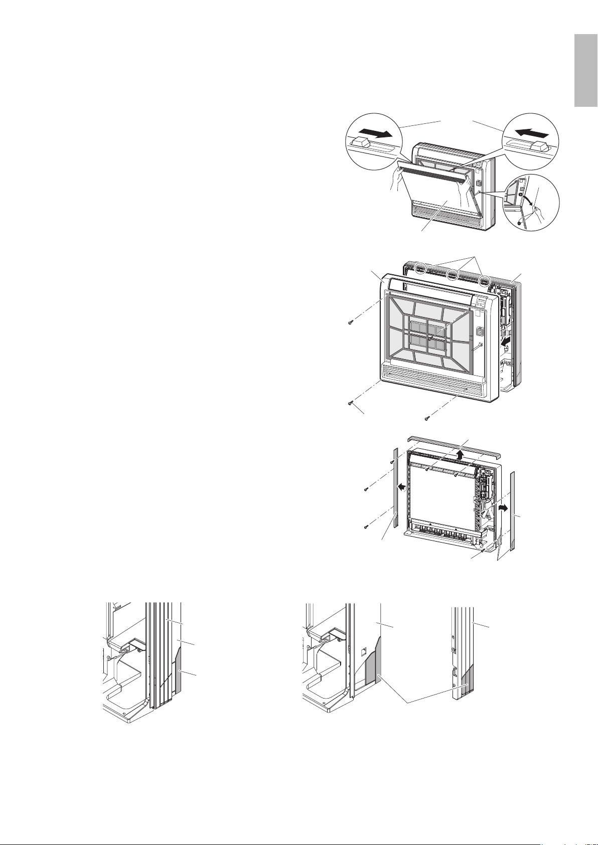
4-1. Preparation
• Remove the front panel.
1) Slide until the 2 stoppers click inside.
2) Open the front panel forward and remove the string.
3) Remove the front panel.
1)Slide the stoppers.
2)Remove the string.
String
Open the front panel
• Remove the front grille.
1) Remove the 4 screws.
2) Pull the front grille and remove the 3 tabs.
Casing
3 tabs
Front grille
4 screws
Remove
front grille
• Remove the upper and the side casings.
1) Remove the 7 screws.
2) Slide and remove the upper casing (2 tabs).
3) Slide and remove the left and right casings (2 tabs on
each side).
Slit portions
Upper casing
7 screws
Side casing
Side
casing
• During installation, if needed, cut the slit portions using
nippers as shown in the illustration below.
[For moldings] [For side piping]
Side casing
Bottom frame
Slit portions
Side casing
Bottom frame
Slit portions
English
01_EN_3P379970-7B.indd 8 11/12/2015 13:29:46
9 ■English
Indoor Unit Installation
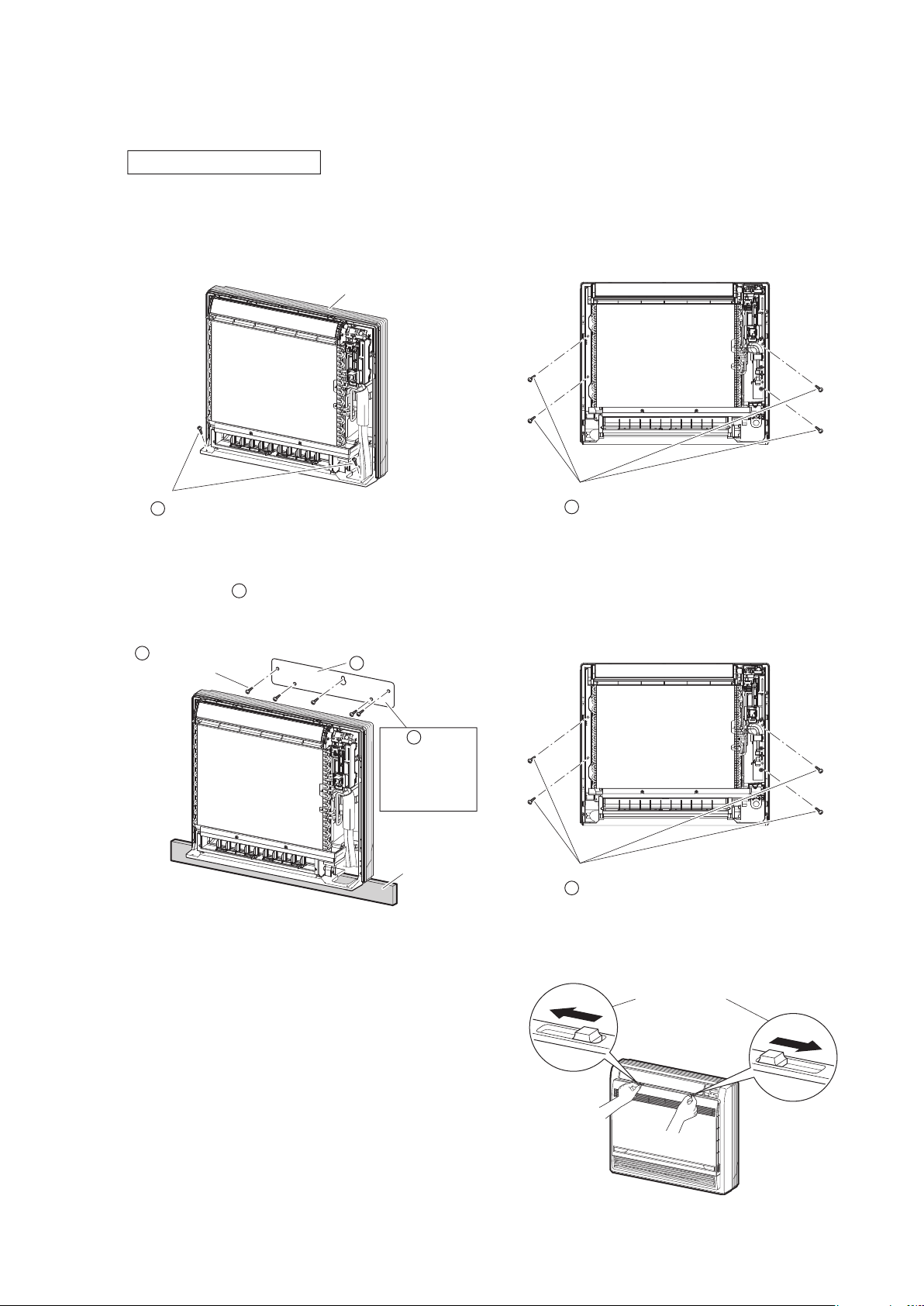
4-2. Installation
Exposed installation
1) Secure the indoor unit
[Floor Installation]
• Secure the indoor unit using 6 screws. (2 screws for oor and 4 screws for rear wall)
Casing
2 screws
Indoor unit fixing screws
3/16” × 1” (M4 × 25mm)
H
4 screws
Indoor unit fixing screws
3/16” × 1” (M4 × 25mm)
H
[Wall Installation]
• Secure the
A
mounting plate using 5 screws.
• Secure the indoor unit using 4 screws for rear wall.
Mounting plate
A
Molding
The mounting
plate should be
installed on a wall
which can support
the weight of the
indoor unit.
A
5 screws
Indoor unit fixing screws
3/16” × 1” (M4 × 25mm)
H
4 screws
Indoor unit fixing screws
3/16” × 1” (M4 × 25mm)
H
2) Once refrigerant piping and drain piping connections are complete, ll in the gap of the through hole with putty.
Any gaps will result in the accumulation of condensation on the refrigerant pipe and drain pipe, as well as
allowing the intrusion of insects and dirt.
3) Attach the left, right and upper casings in their original
positions using 7 screws.
4) Attach the front grill in its original position using 4 screws.
5) Attach the front panel in its original position.
• Attach the string to the right, inner-side of the front grille.
• Close the front panel and slide until the 2 stoppers click
outside.
Slide the stoppers
01_EN_3P379970-7B.indd 9 11/12/2015 13:29:52
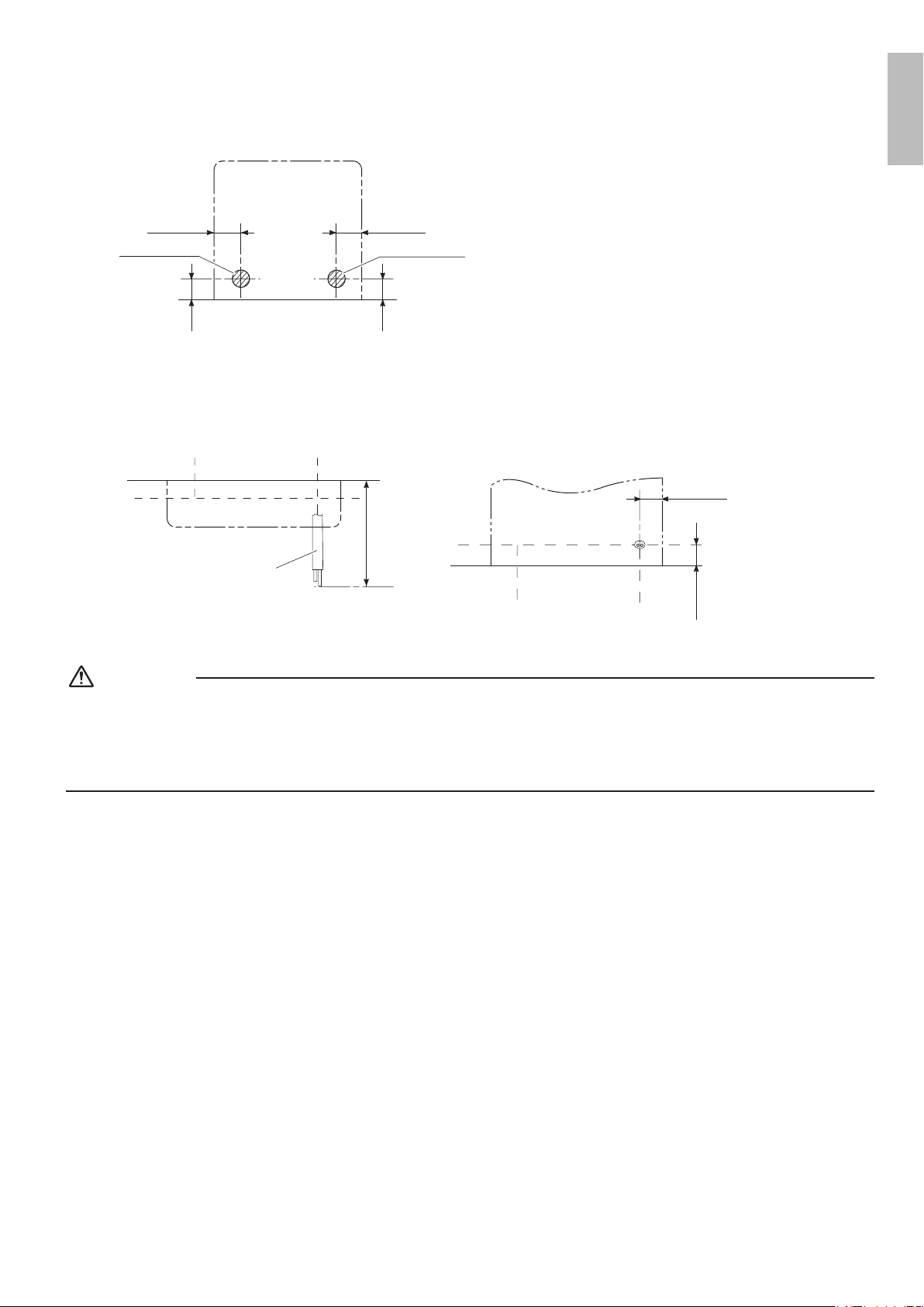
10■English
Half concealed installation
1) The size of a wall opening space shown in the illustration on
the right.
26-3/8 – 27-3/16
(670-690)
23-1/16 – 23-7/16
(585 – 595)
unit: inch (mm)
Open size
Opening space
Floor
2) The rear of the unit can be xed with screws at the points shown in the illustration as below. Be sure to install the propping
object in accordance with the depth of the inner wall.
Fixing point
on the back
Propping object
(field supply)
5-1/2 (140)
9-1/16 (230)
25-3/8 (644)
Screw hole
Screw hole
Opening hole
5-7/8 (150)
9-13/16 (250)
3-3/4 (95)
Propping object
(field supply)
9-13/16 (250)
7-7/8 (200)
unit: inch (mm)
CAUTION
The propping object for installing the main unit must be used, or there will be a gap between the unit and the wall.
3) Secure the indoor unit using 6 screws. (2 screws for oor and 4 screws for rear wall)
2 screws
Indoor unit fixing screws
3/16” × 1” (M4 × 25mm)
H
4 screws
Indoor unit fixing screws
3/16” × 1” (M4 × 25mm)
H
4) Once refrigerant piping and drain piping connections are complete, ll in the gap of the through hole with putty.
Any gaps will result in the accumulation of condensation on the refrigerant pipe and drain pipe, as well as allowing
the intrusion of insects and dirt.
5) Attach the left, right and upper casings in their original positions
using 7 screws.
6) Attach the front grill in its original position using 4 screws.
7) Attach the front panel in its original position.
• Attach the string to the right, inner-side of the front grille.
• Close the front panel and slide until the 2 stoppers click outside.
Slide the stoppers
CAUTION
• Use drain pan edge for horizontal projection of the indoor unit.
• Install the indoor unit ush against wall.
English
01_EN_3P379970-7B.indd 10 11/12/2015 13:29:55
11 ■English
Indoor Unit Installation
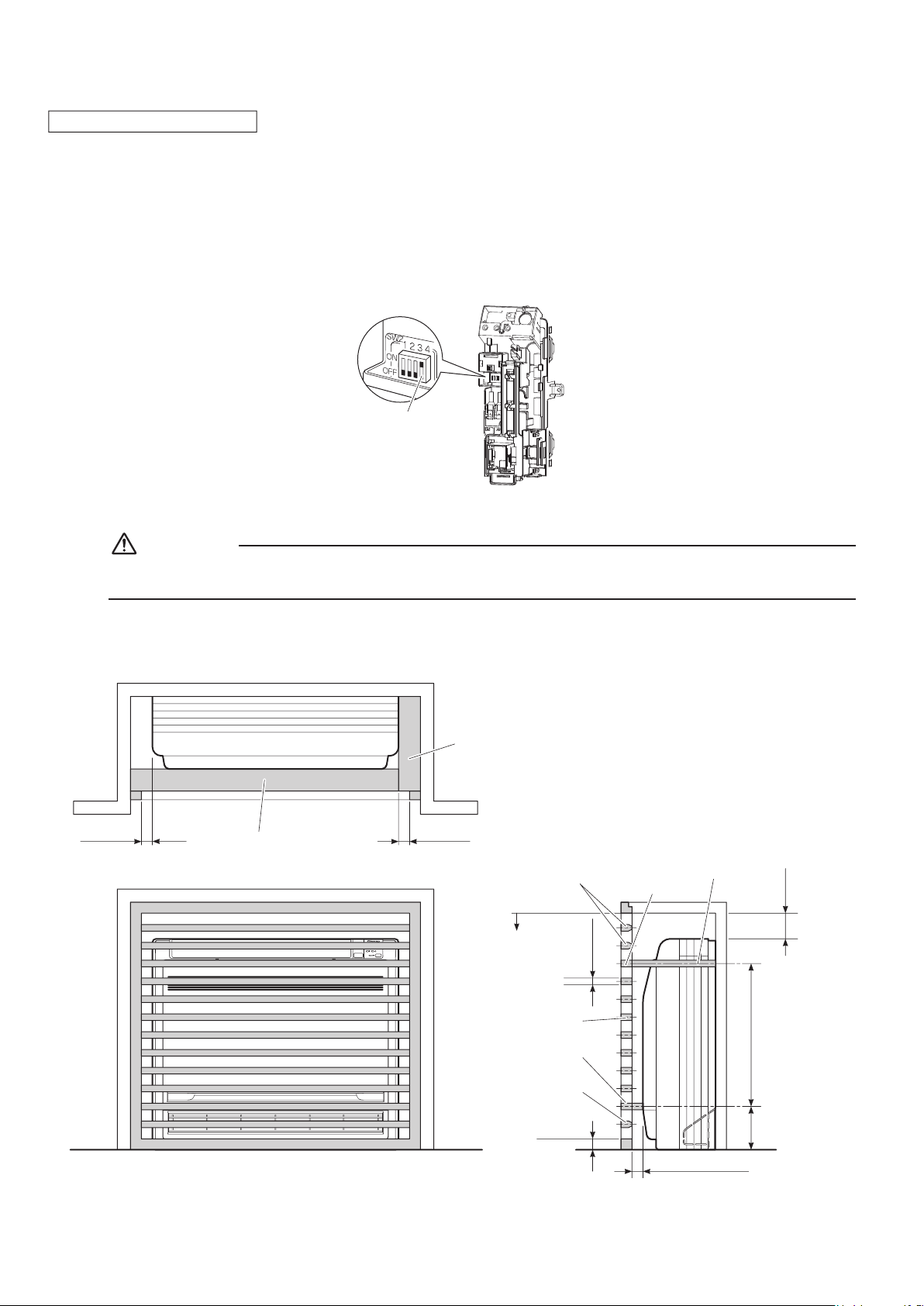
Concealed installation
• Install the unit according to the instructions below. Failure to do so may cause lead to both cooling and heating failure and the
condensation inside the house.
1) Allow enough space between the main unit and ceiling not to obstruct the ow of cool/warm air.
2) Place a partition plate between outlet and inlet sections.
3) Place a partition plate on the right side.
4) Change the upward airow dipswitch (SW2-4) to ON to limit the upward airow. (Factory default: OFF)
• Remove the front grille.
• Switch the dipswitch (SW2-4) on the PCB in the electrical equipment box to ON.
Upward airflow dipswitch
CAUTION
Be sure to turn on the upward airow switch. Failure to do so may cause incomplete cooling/heating and formation
of condensation inside the house.
5) Use a movable lattice at the air outlet to allow the adjustment of cool/warm airow direction.
6) Lattice size should be 70% or more of open rate.
Right side partition plate
Partition plate
1-15/16 (50)
or more
1-15/16 (50)
or more
Partition plate
Movable lattice
9/16 – 13/16
(15 – 20)
16-1/8 (410)
4-3/4
(120)
70% or more
of open rate
1-9/16 (40)
or less
13/16
–
1-3/16 (20-30)
Upper lattice
must not
project
Right side partition plate
Partition plate
Movable lattice
2-3/4 (70)
or more
unit: inch (mm)
• For the installation process refer to “Exposed installation” on page 9.
01_EN_3P379970-7B.indd 11 11/12/2015 13:29:56
12■English
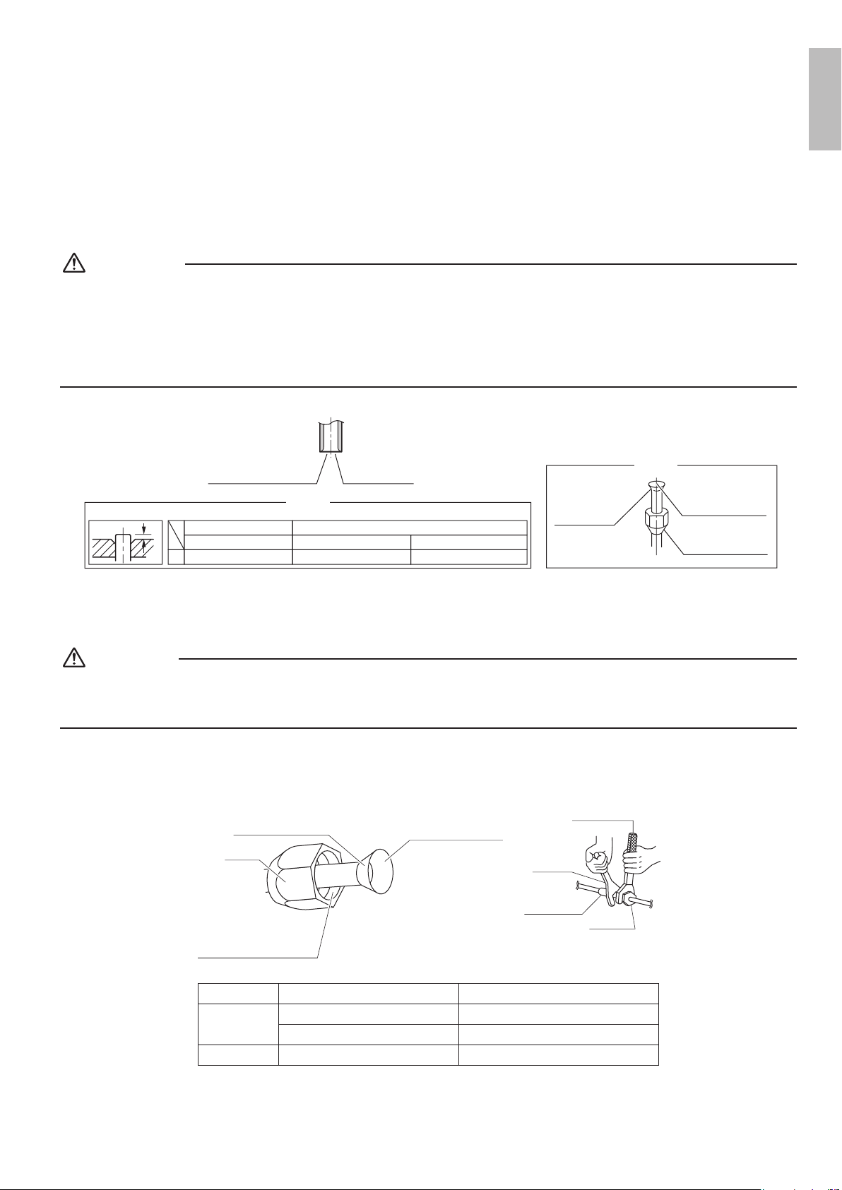
5. Flaring the pipe end
1) Cut the pipe end with a pipe cutter.
2) Remove burrs with the cut surface facing downward, so that the lings do not enter the pipe.
3) Put the are nut on the pipe.
4) Flare the pipe.
5) Check that the aring has been done correctly.
WARNING
• Do not apply mineral oil to the are.
• Prevent mineral oil from getting into the system as this would reduce the service life of the units.
• Never use piping which has been used for previous installations. Only use parts which are delivered with this unit.
• Never install a dryer to this R410A unit in order to guarantee its service life.
• The drying material may dissolve and damage the system.
• Incomplete aring may result in refrigerant gas leakage.
The flare’s inner
surface must
be flaw-free.
The pipe end must
be evenly flared in
a perfect circle.
Make sure that the
flare nut is fitted.
Set exactly at the position shown below.
A
Flaring
Die
A 0-0.020 inch (0-0.5mm)
Clutch-type
Flare tool for R410A
0.039-0.059 inch (1.0-1.5mm)
Clutch-type (Rigid-type)
0.059-0.079 inch (1.5-2.0mm)
Wing-nut type (Imperial-type)
Conventional flare tool
Cut exactly at right angles.
Remove burrs
Check
6. Connecting the refrigerant pipe
CAUTION
• Use the are nut xed to the main unit. (This is to prevent the are nut from cracking as a result of deterioration over time.)
• To prevent gas leakage, apply refrigeration oil only to the inner surface of the are. (Use refrigeration oil for R410A.)
• Use a torque wrench when tightening the are nuts to prevent damage to the are nuts and gas leakage.
• Align the center of both ares and tighten the are nuts 3 or 4 turns by hand, then tighten them fully with a spanner and a
torque wrench.
Torque wrench
Piping union
Flare nut
Do not apply refrigeration
oil to the outer surface.
Flare nut
Apply refrigeration oil to
the inner surface of the
flare.
Do not apply refrigeration oil to
the flare nut to avoid tightening
with excessive torque.
Spanner
Apply oil Tighten
Piping size Flare nut tightening torque
Gas side
O.D. 3/8 inch (9.5mm) 24.1-29.4ft • Ibf (32.7-39.9N • m)
O.D. 1/2 inch (12.7mm) 36.5-44.5ft • lbf (49.5-60.3N • m)
Liquid side O.D. 1/4 inch (6.4mm) 10.5-12.7ft • lbf (14.2-17.2 N • m)
English
01_EN_3P379970-7B.indd 12 11/12/2015 13:29:57
13 ■English
Indoor Unit Installation
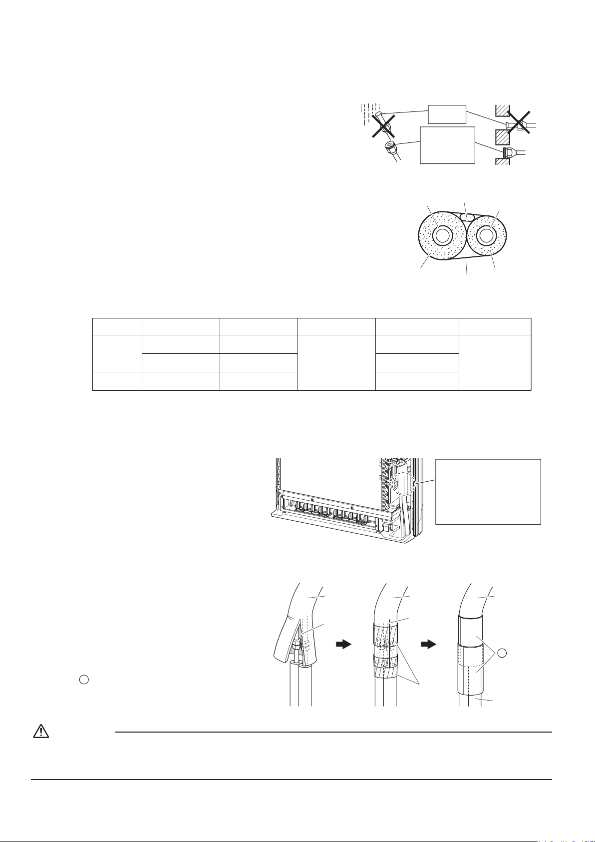
6-1. Caution on piping handling
1) Protect the open end of the pipe against dust and moisture.
2) All pipe bends should be as gentle as possible. Use a pipe
bender for bending.
Wall
If no flare cap is
available, cover
the flare mouth
with tape to keep
dirt or water out.
Be sure to
place a cap.
Rain
6-2. Selection of copper and heat insulation materials
When using commercial copper pipes and ttings, observe the following:
• Insulation material: Polyethylene foam
Heat transfer rate: 0.041 to 0.052W/mK (0.024 to 0.030Btu/fth°F
(0.035 to 0.045kcal/mh°C))
Be sure to use insulation that is designed for use with HVAC Systems.
• ACR Copper only.
Liquid pipe
Gas pipe
Gas pipe
insulation
Liquid pipe
insulation
Finishing tape
Inter-unit wiring
• Be sure to insulate both the gas and liquid piping and observe the insulation dimensions as below.
Gas side
Piping size
O.D. 3/8 inch
(9.5mm)
O.D. 1/2 inch
(12.7mm)
O.D. 1/4 inch
(6.4mm)
1-3/16 inch (30mm)
or more
1-9/16 inch (40mm)
or more
1-3/16 inch (30mm)
or more
0.031 inch (0.8mm)
(C1220T-O)
I.D. 15/32-19/32 inch
(12-15mm)
I.D. 9/16-5/8 inch
(14-16mm)
I.D. 5/16-13/32 inch
(8-10mm)
13/32 inch
(10mm) Min.
Minimum bend radius Piping thickness Thermal insulation size
Thermal insulation
thickness
Liquid side
• Use separate thermal insulation pipes for gas and liquid refrigerant pipes.
7. Checking for gas leakage
1) Check for leakage of gas after air purging.
2) Refer to the section on pressure test and
evacuating system in the installation manual
for the outdoor unit.
Check for leakage here.
• Apply soapy water and
check carefully for leaking
gas.
• Wipe soapy water off after
the check is complete.
8. Attaching the connection pipe
• Attach the pipe after checking for gas leakage,
described above.
1) Cut the insulated portion of the on-site piping,
matching it up with the connecting portion.
2) Secure the slit on the refrigerant piping side
with the butt joint on the auxiliary piping using
the tape, making sure there are no gaps.
3) Wrap the slit and the butt joint with the
D
insulation tape, making sure there are no
gaps.
Refrigerant
pipe
Refrigerant
pipe
Refrigerant
pipe
2)1) 3)
Auxiliary pipe
Slit
Slit
Tape
Insulation
tape
D
CAUTION
• Insulate the joint of the pipes securely.
Incomplete insulation may lead to water leakage.
• Push the pipe inside so it does not place undue force on the front grille.
01_EN_3P379970-7B.indd 13 11/12/2015 13:29:58
14■English
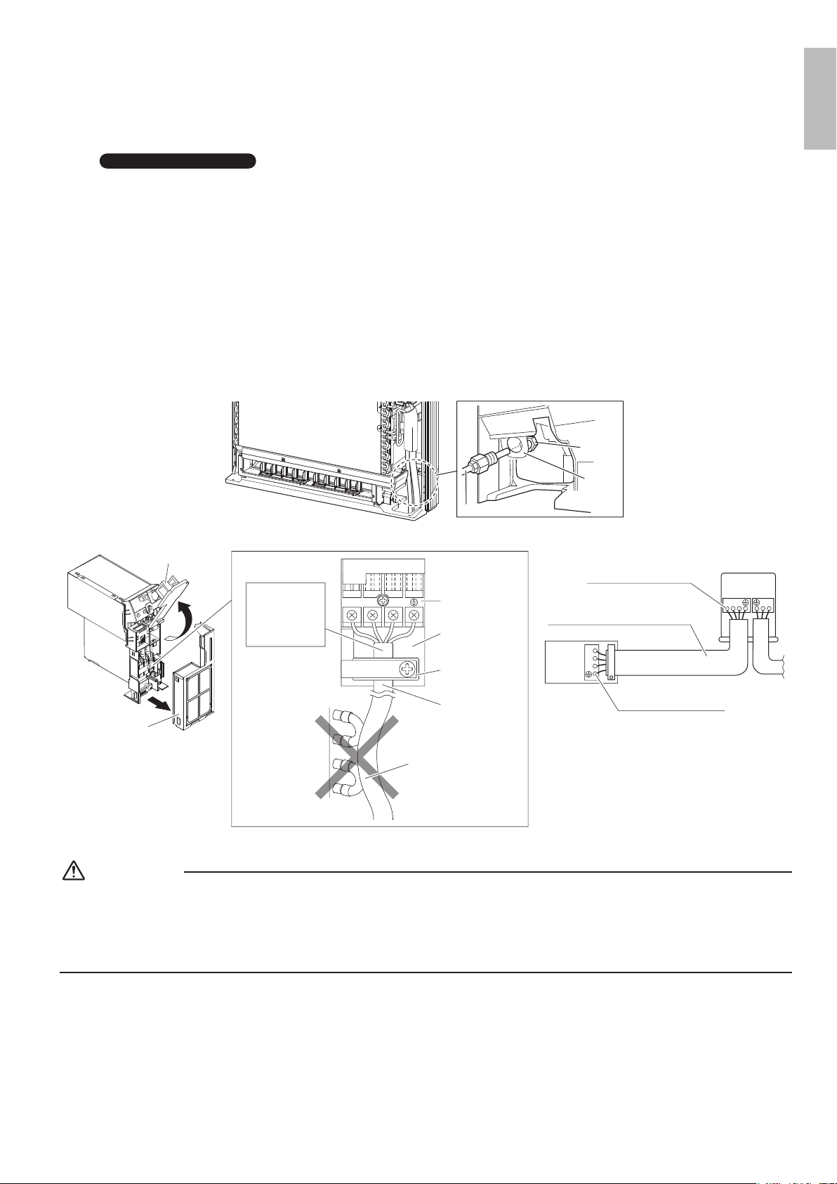
9. Wiring
With a multi indoor unit
, install as described in the installation manual supplied with the multi outdoor unit.
• Live the sensor securing plate, remove the front electrical wiring box cover, and connect the branch wiring to the terminal
block.
1) As shown in the illustration, insert the wires including the ground wire into the conduit and secure them with lock nut
onto the conduit mounting plate.
2) Strip wire ends (3/4 inch (20mm)).
3) Match wire colours with terminal numbers on indoor and outdoor unit’s terminal blocks and rmly secure the wires in
the corresponding terminals with the screws.
4) Connect the ground wires to the corresponding terminals.
5) Pull the wires lightly to make sure they are securely connected.
6) Make sure that the wires do not come in contact with the metal conduit for the heat exchanger.
7) In case of connecting to an adapter system, run the remote controller cable and attach the S21. (Refer to “10. When
connecting to an HA system” on page 15.)
Conduit
mounting
plate
Conduit
Lock nut
Back
1
2
3
123
L
2
123
L
1
Firmly fix the wires with
the terminal screws.
Outdoor unit
Indoor
unit
Firmly fix the wires with
the terminal screws.
Use AWG16 if the connection wire
length is less than 33ft (10m), or
AWG14 if it is 33ft (10m) or more.
Terminal block
Electrical
wiring
box
Wire retainer
Use the specified
wire type.
Make sure that the wires
do not come in contact
with the metal conduit
for the heat exchanger.
Shape wires so
that the front
electrical wiring
box cover will fit
securely.
Front electrical
wiring box cover
Sensor securing plate
WARNING
• Do not use tapped wires, stranded wires, extension cords, or starburst connections, as they may cause overheating,
electric shock, or re.
• Do not use locally purchased electrical parts inside the product. (Do not branch the power for the drain pump, etc., from the
terminal block.) Doing so may cause electric shock or re.
• Do not connect the power wire to the indoor unit. Doing so may cause electric shock or re.
English
01_EN_3P379970-7B.indd 14 11/12/2015 13:29:59
15 ■English
Indoor Unit Installation
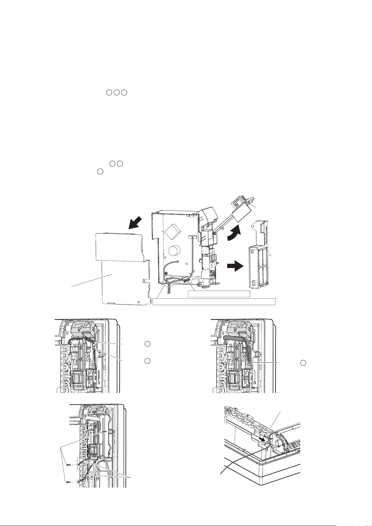
10. When connecting to an HA system
1) Remove the front panel and the front grille. (Refer to “4-1. Preparation” on page 8.)
2) Open up the sensor securing plate. (See Fig. 3)
3) Remove the front electrical wiring box cover (4 tabs). (See Fig. 3)
4) Remove connectors
1
2
3
. (See Fig. 4 and Fig. 5)
5) After removing the ground wires (2 screws), remove the electrical wiring box (1 screw). (See Fig. 6 )
6) Remove the thermistor. (See Fig. 7)
7) Remove the side electrical wiring box cover (7 tabs). (See Fig. 3)
8) Cut off the pins using a nipper. (See Fig. 3)
9) Wire and connect the HA connection cord to the S21 connector. (See Fig. 3)
10)
Install the side electrical wiring box cover while being careful not to pinch the HA connection cord or ground wires (7 tabs).
11) Attach the thermistor.
12) Install the ground wires (2 screws) and the electrical wiring box (1 screw).
13) Install the connectors
1
2
and guide the cord as shown in the gure. (See Fig. 4)
14) Install connector
3
and guide the cord as shown in the gure. (See Fig. 5)
15) Attach the front electrical wiring box cover (4 tabs), and close the sensor securing plate.
16) Attach the front panel and the front grille as they were.
S21
Sensor securing plate
Front electrical
wiring box cover
Side electrical
wiring box cover
Cut off the pins using a nipper.
Be careful not to pinch the HA connection cord or ground wire.
Fig. 3
Connector
1
Connector
2
Connector
3
Fig. 4 Fig. 5
Screws
Ground wires
Thermistor
Fig. 6 Fig. 7
01_EN_3P379970-7B.indd 15 11/12/2015 13:30:03
16■English
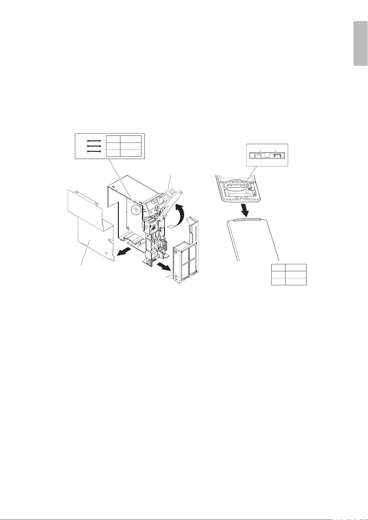
11. How to set the different addresses
• When 2 indoor units are installed in 1 room, the 2 wireless remote controllers can be set for different addresses.
Change the address setting of one of the 2 units.
When cutting the jumper be careful not to damage any of the surrounding parts.
1) Remove the electrical wiring box. (Refer to “10. When connecting to an HA system” on page 15 steps 1)-7).)
2) Cut the address jumper (JA) on the printed circuit board.
3) Cut the address jumper (J4) in the remote controller.
4)
Attach the electrical wiring box as they were. (Refer to “10. When connecting to an HA system” on page 15 steps 10)-15).)
5) Attach the front panel and the front grille as they were.
Jumper
(J8) (J4)
J4
ADDRESS
EXIST
1
CUT 2
JA
ADDRESS
EXIST
1
CUT 2
JA
Front electrical
wiring box cover
Side electrical
wiring box cover
Sensor
securing plate
English
01_EN_3P379970-7B.indd 16 11/12/2015 13:30:04
17 ■English
Trial Operation and Testing
1. Trial operation and testing
• Trial operation should be carried out in either COOL or HEAT operation.
1-1. Measure the supply voltage and make sure that it is within the specied range.
1-2. In COOL operation, select the lowest programmable temperature;
in HEAT operation, select the highest programmable temperature.
1-3. Carry out the trial operation following the instructions in the operation manual to
ensure that all functions and parts, such as the movement of the ap, are working
properly.
• To protect the air conditioner, restart operation is disabled for 3 minutes after the system has been turned off.
•
When connecting to a multi outdoor unit, if trial operation is conducted in HEAT operation directly after the circuit
breaker is turned on, in some cases no air will be output for about 3 to 20 minutes in order to protect the air conditioner.
1-4. After trial operation is complete, set the temperature to a normal level (78°F to 82°F
(26°C to 28°C) in COOL operation, 68°F to 75°F (20°C to 24°C) in HEAT operation).
• When operating the air conditioner in COOL operation in winter, or HEAT operation in summer, set it to the trial operation
mode using the following method.
1) Press
to turn on the system.
2) Press
, and at the same time.
3) Press
, then select “ ”, and press for conrmation.
• Trial operation will stop automatically after about 30 minutes.
To stop the operation, press .
• Some of the functions cannot be used in the trial operation mode.
• The air conditioner draws a small amount of power in its standby mode. If the system is not to be used for some time after
installation, shut off the circuit breaker to eliminate unnecessary power consumption.
• If the circuit breaker trips to shut off the power to the air conditioner, the system will restore the original operation mode
when the circuit breaker is opened again.
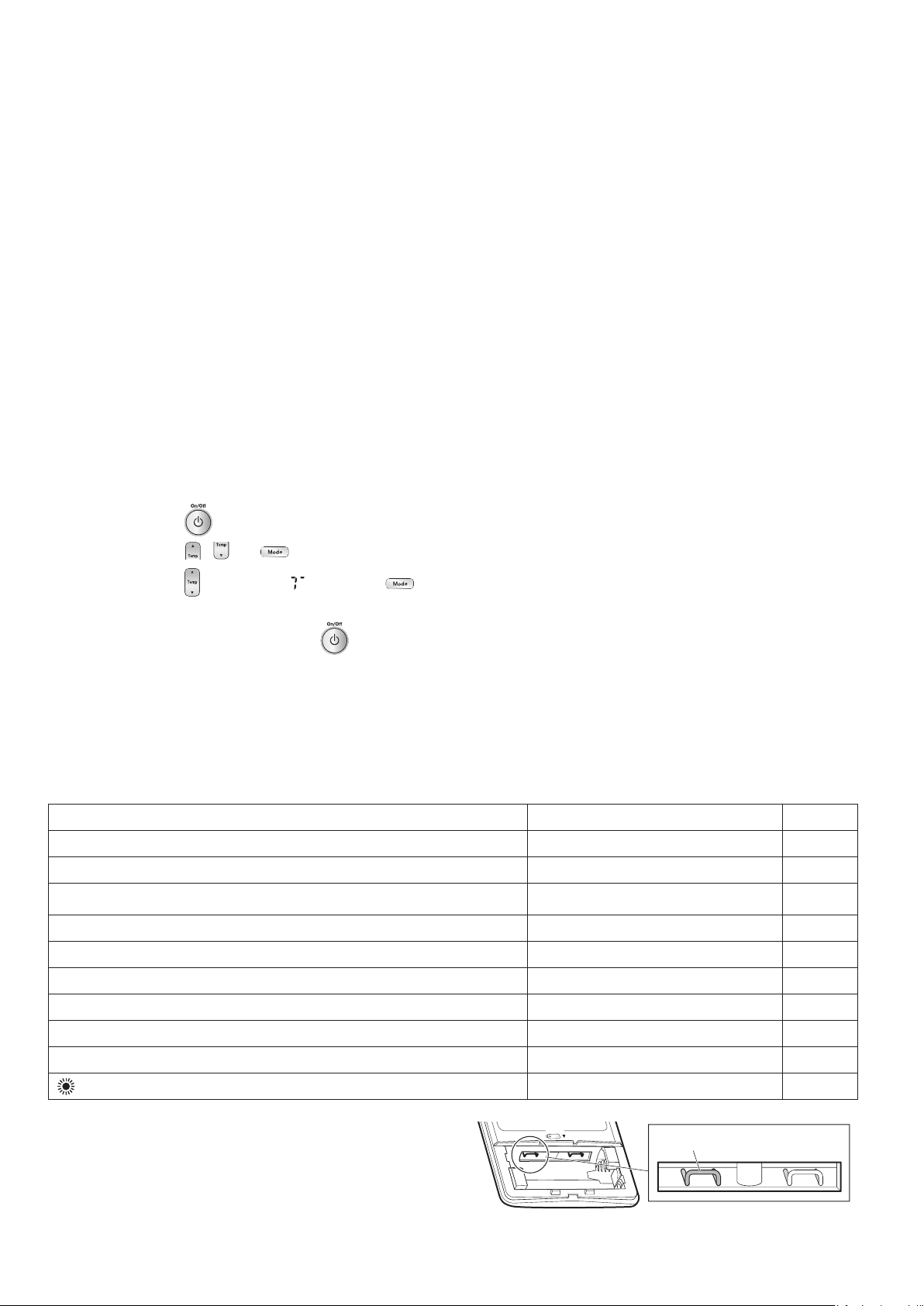
2. Test items
Test Items Symptom Check
Indoor and outdoor units are installed properly on solid bases. Fall, vibration, noise
No refrigerant gas leaks. Incomplete cooling/heating function
Refrigerant gas and liquid pipes and indoor drain hose extension are
thermally insulated.
Water leakage
Draining line is properly installed. Water leakage
System is properly grounded. Electrical leakage
The specied wires are used for inter-unit wiring connections. No operation or burn damage
Indoor or outdoor unit’s air inlet or air outlet are unobstructed. Incomplete cooling/heating function
Stop valves are opened. Incomplete cooling/heating function
Indoor unit properly receives remote control commands. No operation
will be displayed when the MODE button is pressed.*
No heating
*Check that the jumper (J8) has not been cut. If it has been cut, contact
your dealer.
Jumper (J8)
01_EN_3P379970-7B.indd 17 11/12/2015 13:30:05

18■English
MEMO
English
01_EN_3P379970-7B.indd 18 11/12/2015 13:30:05

Two-dimensional bar code
is a manufacturing code.
3P379970-7B
M15B136
(1511)
HT
00_CV_3P379970-7B.indd 2 10/28/2015 20:12:06