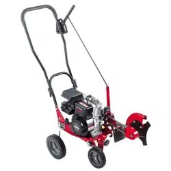
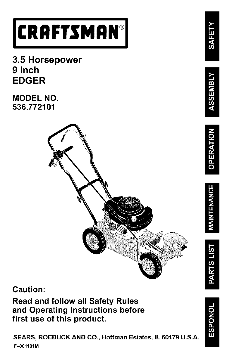
3.5 Horsepower
9 Inch
EDGER
MODEL NO.
536.772101
Caution:
Read and follow all Safety Rules
and Operating Instructions before
first use of this product.
SEARS, ROEBUCK AND CO., Hoffman Estates, IL 60179 U.S.A.
F_)01101M
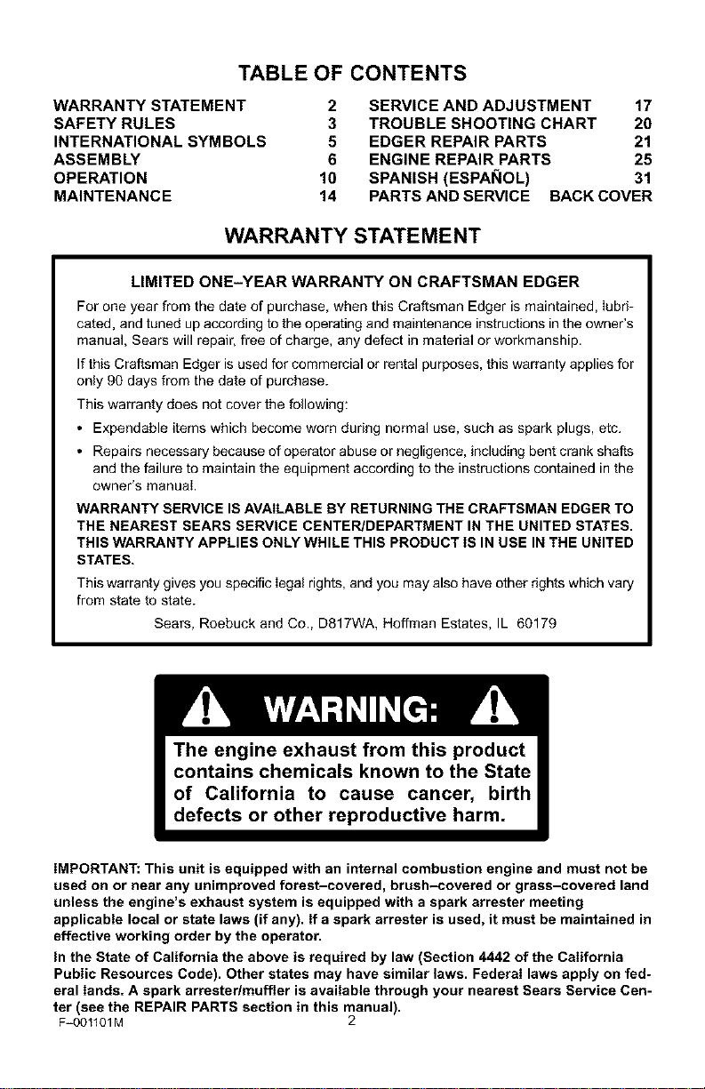
TABLE OF CONTENTS
WARRANTY STATEMENT
SAFETY RULES
INTERNATIONAL SYMBOLS
ASSEMBLY
OPERATION
MAINTENANCE
2 SERVICE AND ADJUSTMENT 17
3 TROUBLE SHOOTING CHART 20
5 EDGER REPAIR PARTS 21
6 ENGINE REPAIR PARTS 25
10 SPANISH (ESPAI_IOL) 31
14 PARTS AND SERVICE BACK COVER
WARRANTY STATEMENT
LIMITED ONE-YEAR WARRANTY ON CRAFTSMAN EDGER
For one year from the date of purchase, when this Craftsman Edger is maintained, lubri-
cated, and tuned up according to the operating and maintenance instructions in the owner's
manual, Sears will repair, free of charge, any defect in material or workmanship.
If this Craftsman Edger is used for commercial or rental purposes, this warranty applies for
only 90 days from the date of purchase.
This warranty does not cover the following:
• Expendable items which become worn during normal use, such as spark plugs, etc.
• Repairs necessary because of operator abuse or negligence, including bent crank shafts
and the failure to maintain the equipment according to the instructions contained in the
owner's manual
WARRANTY SERVICE IS AVAILABLE BY RETURNING THE CRAFTSMAN EDGER TO
THE NEAREST SEARS SERVICE CENTER/DEPARTMENT IN THE UNITED STATES.
THIS WARRANTY APPLIES ONLY WHILE THIS PRODUCT IS IN USE IN THE UNITED
STATES.
This warranty gives you specific Iegal rights, and you may also have other rights which vary
from state to state.
Sears, Roebuck and Co., D817WA, Hoffman Estates, IL 60179
IMPORTANT: This unit is equipped with an internal combustion engine and must not be
used on or near any unimproved forest-covered, brush-covered or grass-covered land
unless the engine's exhaust system is equipped with a spark arrester meeting
applicable local or state laws (if any). If a spark arrester is used, it must be maintained in
effective working order by the operator.
in the State of California the above is required by law (Section 4442 of the California
Public Resources Code). Other states may have similar laws. Federal laws apply on fed-
eral lands. A spark arrestedmuffler is available through your nearest Sears Service Cen-
ter (see the REPAIR PARTS section in this manual).
F=00tl01M 2

SAFETY RULES
Safe Operation Practices for Edger.
WARNING: Look for this symbol to point out important safety precautions.
It means: "Attention! Become Alertt Your Safety Is Involved."
_lb ARNING: To prevent acciden-
tal starting when setting-up,
transporting, adjustin9 or mak-
ing repairs, always disconnect spark
plug wire and put wire where it cannot
contact the spark plug.
Before Use
• Read the owner's manual carefully. Be
thoroughly familiar with the controls and
the proper use of the Edger. Know how to
stop the Edger and disengage the controls
quickly.
• Do not operate the Edger without wearing
adequate outer garments. Wear footwear
that will improve footing on slippery sur-
faces.
• Keep the area of operation clear of all per-
sons, particularly small children and pets.
• Thoroughly inspect the area where the
Edger is to be used and remove all foreign
objects.
Fuel Safety
• Handle fuel with care; it is highly flam-
mable.
• Use an approved container.
• Check fuel supply before each use, allow-
ing space for expansion as the heat of the
engine and/or sun can cause fuel to ex-
pand.
• Fill fueI tank outdoors with extreme care.
Never fill fuel tank indoors. Replace fuel
tank cap securely and wipe up spilled fuel.
• Never remove the fuel tank cap or add fuel
to a running or hot engine.
• Never store fuel or Edger with fuel in the
tank inside a building where fumes may
reach an open flame.
F_)OllO1M
Operating Safety
• Never allow children or young teenagers to
operate the Edger'. Keep them away while
it is operating. Never allow aduits to oper-
ate the Edger without proper instruction.
• Do not operate this machine if you are tak-
ing drugs or other medication which can
cause drowsiness or affect your ability to
operate this machine.
• Do not use this machine if you are mentaily
or physically unable to operate this ma-
chine safely.
• Always wear safety glasses or eye shields
during operation or while performing an
adjustment or repair to protect your eyes
from foreign objects that may be thrown
from the Edger.
• Do not put hands or feet near or under ro-
tating parts.
• Exercise extreme caution when operating
on or crossing gravel drives, walks, or
roads. Stay alert for hidden hazards or
traffic.
• Exercise caution to avoid slipping or falling.
• Never operate the Edger without proper
guards, plates, or other safety protective
devices in place.
• Never operate the Edger at high transport
speeds on slippery surfaces. Look behind
and use care when backing.
• Never allow bystanders near the Edger.
• Keep children and pets away while
operating.
• Never operate the Edger without good visi-
bility or light.
• Do net run the engine indoors. The ex-
haust fumes are dangerous, containing
CARBON MONOXIDE, an ODORLESS
and DEADLY GAS.
• Take aiI possib% precautions when leaving
the Edger unattended. Stop the engine.
• DOnot overload the Edger capacity by at-
tempting to till too deep at too fast a rate.
3
Safe Storage
• Always refer to the owner's manual instruc-
tions for important details if the Edger is to
be stored for an extended period.
SAFETY RULES
spect the Edger for any damage, and re-
pair the damage before restarting and
operating it.
• Never store the Edger with fuel in the fuel
tank inside a building where ignition
sources are present such as water and
space heaters, clothes dryers, and the like.
Allow the engine to cool before storing in
any enclosure.
• Keep the Edger in safe working condition.
Check all fasteners at frequent intervals for
proper tightness.
Repair / Adjustments Safety
If Edger should start to vibrate abnormally,
stop engine and check immediately for the
cause. Vibration is generally a warning of
trouble.
• Stop the engine whenever you leave the
operating position. Also, disconnect the
spark plug wire before unclogging the
blade and when making any repairs, ad-
justments, or inspections.
When cleaning, repairing, or inspecting,
shut off the engine and make certain all
moving parts have stopped.
• After striking a foreign object, stop the en-
gine. Remove the wire from the spark plug,
and keep the wire away from the plug to
prevent accidental starting. Thoroughly in-
Never attempt to make any adjustments
while the engine is running except when
specifically recommended by the manufac-
turer.
F_001101M 4
SAFETY RULES
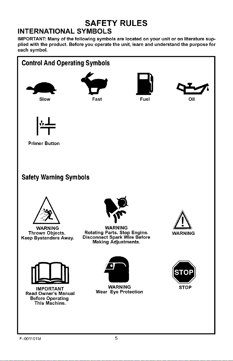
INTERNATIONAL SYMBOLS
IMPORTANT: Many of the following symbols are located on your unit or on literature sup-
plied with the product. Before you operate the unit, learn and understand the purpose for
each symbol.
ControlAnd OperatingSymbols
Slow Fast Fuel Oil
Primer Button
Safety Warning Symbols
WARNING WARNING
Thrown Objects. Rotating Parts. Stop Engine. WARNING
Keep Bystanders Away, Disconnect Spark Wire Before
Making Adjustments,
IMPORTANT WARNING STOP
Read Owner's Manual Wear Eye Protection
Before Operating
This Machine.
F_OO1101M 5
ASSEMBLY
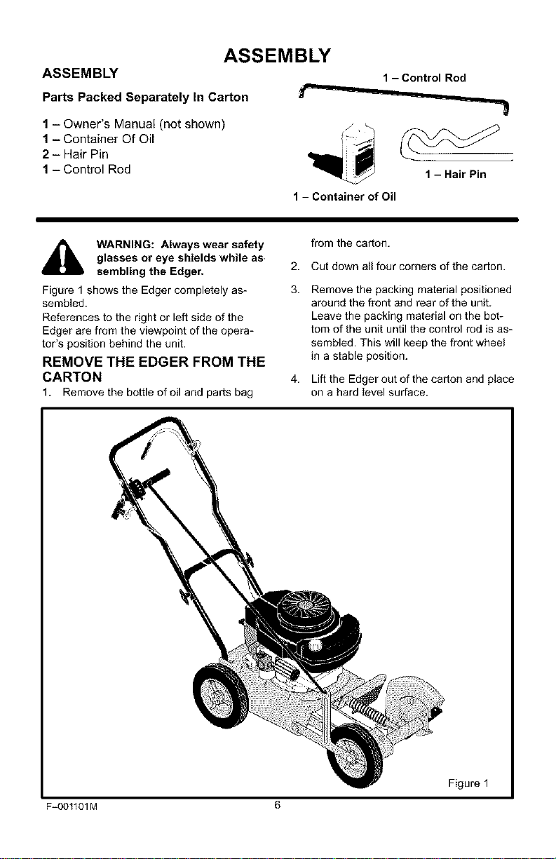
ASSEMBLY
Parts Packed Separately In Carton
1 - Owner's Manual (not shown)
1 - Container Of Oil
2 - Hair Pin
1 - Control Rod
1 - Control Rod
1 - Container of Oil
1 -HairPin
_lb WARNING: Always wear safety
glasses or eye shields while as,
sembling the Edger.
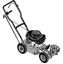
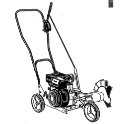
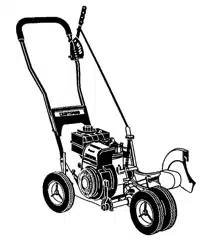
Figure 1 shows the Edger completely as-
sembled.
References to the right or left side of the
Edger are from the viewpoint of the opera-
tot's position behind the unit.
REMOVE THE EDGER FROM THE
CARTON
1. Remove the bottle of oil and parts bag
2.
3.
4.
from the carton.
Cut down all four corners of the carton.
Remove the packing material positioned
around the front and rear of the unit.
Leave the packing material on the bot-
tom of the unit until the control rod is as-
sembled. This will keep the front wheel
in a stable position.
Lift the Edger out of the carton and place
on a hard level surface.
Figure 1
F_OO1101M 6
ASSEMBLY
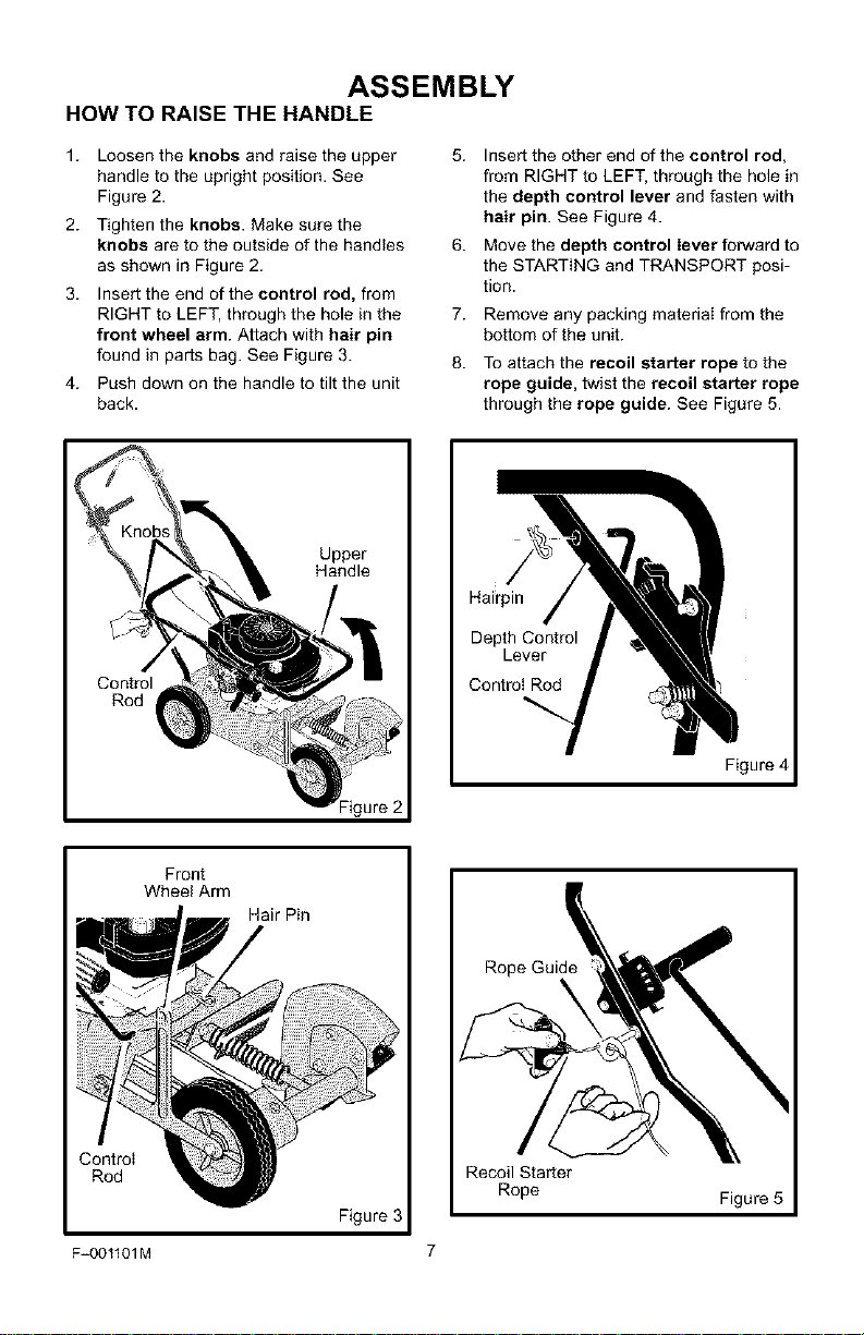
HOW TO RAISE THE HANDLE
1. Loosen the knobs and raise the upper
handle to the upright position. See
Figure 2.
2. Tighten the knobs. Make sure the
knobs are to the outside of the handles
as shown in Figure 2.
3. Insert the end of the control rod, from
RIGHT to LEFT, through the hole in the
front wheel arm. Attach with hair pin
found in parts bag. See Figure 3.
4. Push down on the handle to tilt the unit
back.
6.
7.
8.
Insert the other end of the control rod,
from RIGHT to LEFT, through the hole in
the depth control lever and fasten with
hair pin. See Figure 4.
Move the depth control lever forward to
the STARTING and TRANSPORT posi-
tion.
Remove any packing material from the
bottom of the unit.
To attach the recoil starter rope to the
rope guide, twist the recoil starter rope
through the rope guide. See Figure 5.
Control
Rod
Upper
Handle
Figure 2
Hai;rpin
Depth Control
Lever
Control Rod
Figure 4
Front
Wheel Arm
ControI
Rod
Hair Pin
Figure 3
Recoil Starter
Rope
Figure 5
F_001101M 7
ASSEMBLY
HOW TO PREPARE THE ENGINE
Fill With Oil
This Edger was shipped with a 20 ounce
container of SAE30 motor oil. Add this oil to
the engine before operating. To fill the crank-
case, remove the oil fill cap/dipstick and add
the SAE30 motor oil. DO NOT OVERFILL.
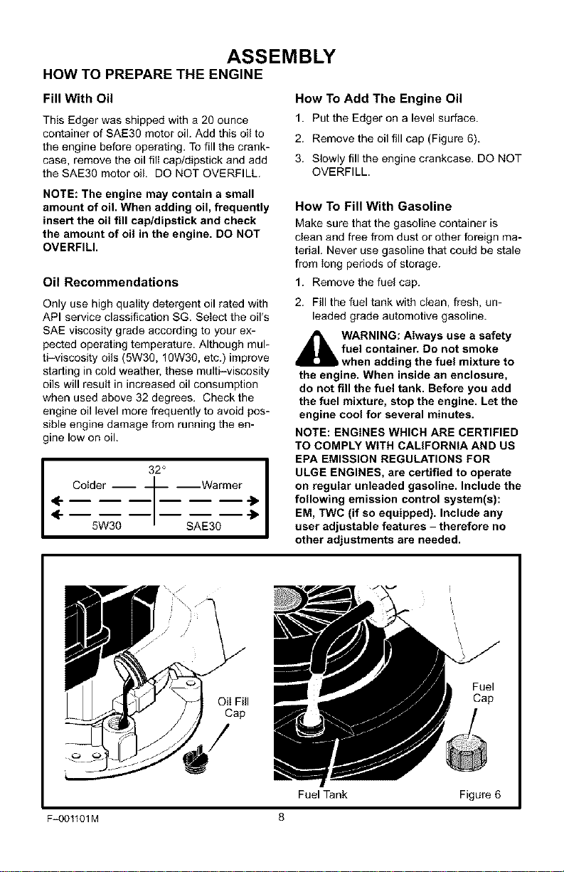
How To Add The Engine Oil
1. Put the Edger on a level surface.
2. Remove the oil fill cap (Figure 6).
3. Slowly fill the engine crankcase. DO NOT
OVERFILL.
NOTE: The engine may contain a small
amount of oil. When adding oil, frequently
insert the oil fill cap/dipstick and check
the amount of oil in the engine. DO NOT
OVERFILl.
Oil Recommendations
Only use high quality detergent oil rated with
API service classification SG. Select the oil's
SAE viscosity grade according to your ex-
pected operating temperature. Although mul-
ti-viscosity oils (5w3g, lOW30, etc.) improve
starting in cold weather, these multi-viscosity
oils will result in increased oil consumption
when used above 32 degrees. Check the
engine oil level more frequently to avoid pos-
sible engine damage from running the en-
gine low on oil.
<-
<-
32 I
Colder ---'I --Warmer
5W30 SAE30
How To Fill With Gasoline
Make sure that the gasoline container is
clean and free from dust or other foreign ma-
terial. Never use gasoline that could be stale
from long periods of storage.
1. Remove the fuel cap.
2. Fill the fuel tank with clean, fresh, un-
leaded grade automotive gasoline.
_l ARNING: Always use a safety
fuel container. Do not smoke
when adding the fuel mixture to
the engine. When inside an enclosure,
do not fill the fuel tank. Before you add
the fuel mixture, stop the engine. Let the
engine cool for several minutes.
NOTE: ENGINES WHICH ARE CERTIFIED
TO COMPLY WITH CALIFORNIA AND US
EPA EMISSION REGULATIONS FOR
ULGE ENGINES, are certified to operate
on regular unleaded gasoline. Include the
following emission control system(s):
EM, TWC (if so equipped). Include any
user adjustable features - therefore no
other adjustments are needed.
Oil Fill
Cap
Fuel
Cap
Fuel Tank Figure 6
F-OOtlOIM 8
ASSEMBLY
_" CHECKLIST
For the best performance and satisfaction
from this quality product, please review the
following checklist before you operate the
Edger:
#-" All assembly instructions have been
completed.
Check carton. Make sure no loose
parts remain in the carton.
All fasteners have been properly tight-
ened.
As you learn how to use the Edger, pay extra
attention to the following important items:
_'#" Engine oil is at proper level.
_'_" Fuel tank is filled with a fresh, clean,
regular Unleaded gasoline.
_'_" Become familiar and understand the
function of all controls. Before your
start the engine, operate all controls.
F-OOllOIM 9
OPERATION
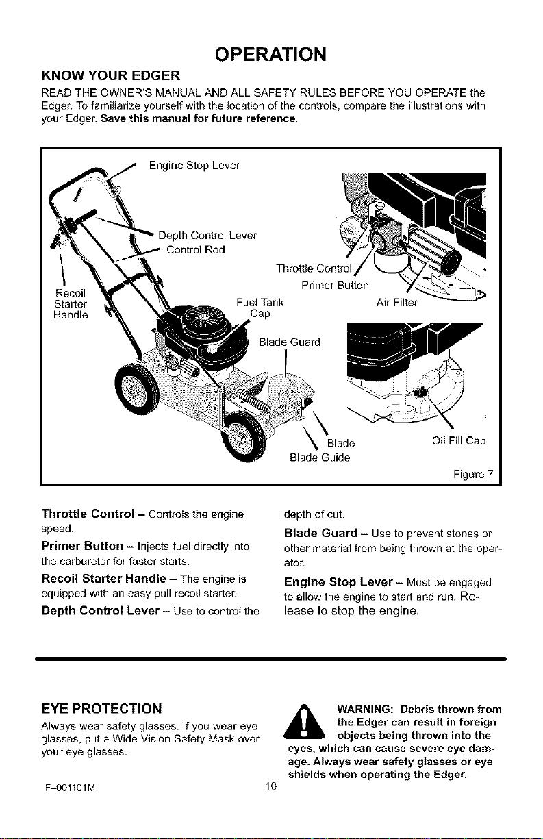
KNOW YOUR EDGER
READ THE OWNER'S MANUAL AND ALL SAFETY RULES BEFORE YOU OPERATE the
Edger. To familiarize yourself with the location of the controls, compare the illustrations with
your Edger. Save this manual for future reference.
Engine Stop Lever
Recoil
Starter
Handle
Depth Control Lever
Control Rod
Throttle Control
Fuel Tank
Cap
Blade Guard
Air Filter
Blade Oil Fill Cap
Blade Guide
Figure 7
Throttle Control - Controls the engine
speed.
Primer Button - Injects fuel directly into
the carburetor for faster starts.
Recoil Starter Handle - The engine is
equipped with an easy pull recoil starter.
Depth Control Lever - Use to control the
depth of cut.
Blade Guard - Use to prevent stones or
other material from being thrown at the oper-
ator.
Engine Stop Lever- Must be engaged
to allow the engine to start and run. Re-
lease to stop the engine.
EYE PROTECTION
Always wear safety glasses. If you wear eye
glasses, put a Wide Vision Safety Mask over
your eye glasses.
F-OO1101M
10
WARNING: Debris thrown from
the Edger can result in foreign
objects being thrown into the
eyes, which can cause severe eye dam-
age. Always wear safety glasses or eye
shields when operating the Edger.
OPERATION
_IL ARNING: When the engine
runs, the blade will rotate. To
prevent injury, keep hands and
feet away from blade.
HOW TO STOP THE EDGER
1. Move the depth control lever forward to
raise the blade. Then, release the engine
stop lever. See Figure 8.
_lb WARNING: Never leave the
Edger unattended while the en-
gine is running. Always raise
the cutting blade and stop the engine.
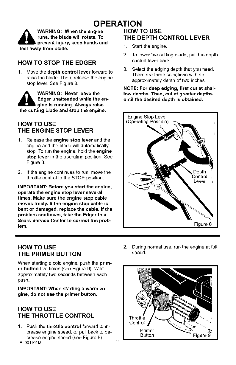
HOW TO USE
THE ENGINE STOP LEVER
1. Release the engine stop lever and the
engine and the blade will automatically
stop. To run the engine, hold the engine
stop lever in the operating position. See
Figure 8.
2. If the engine continues to run, move the
throttle control to the STOP position.
IMPORTANT: Before you start the engine,
operate the engine stop lever several
times. Make sure the engine stop cable
moves freely. If the engine stop cable is
bent or damaged, replace the cable. If the
problem continues, take the Edger to a
Sears Service Center to correct the prob-
lem.
HOW TO USE
THE DEPTH CONTROL LEVER
1. Start the engine.
2. To lower the cutting blade, pull the depth
control lever back.
3. Select the edging depth that you need.
There are three selections with an
approximately depth of two inches.
NOTE: For deep edging, first cut at shal-
low depths. Then, cut at greater depths
until the desired depth is obtained.
Engine Stop Lever
(Operating Position)
Figure 8
HOW TO USE
THE PRIMER BUTTON
When starting a cold engine, push the prim-
er button five times (see Figure 9). Wait
approximately two seconds between each
push.
IMPORTANT: When starting a warm en-
gine, do not use the primer button.
HOW TO USE
THE THROTTLE CONTROL
1. Push the throttle control forward to in-
crease engine speed, or pull back to de-
crease engine speed (see Figure 9).
F=OO1101M
2. During normal use, run the engine at full
speed.
11
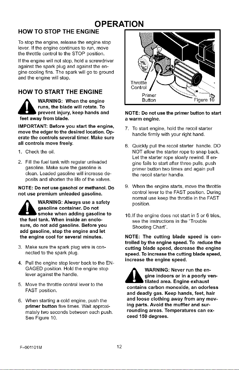
Throttle
Primer
Button Figure 9
OPERATION
HOW TO STOP THE ENGINE
To stop the engine, release the engine stop
ieven If the engine continues to run, move
the throttle control to the STOP position.
If the engine will not stop, hold a screwdriver
against the spark plug and against the en-
gine cooling fins. The spark will go to ground
and the engine will stop.
HOW TO START THE ENGINE
,_ WARNING: When the engine
runs, the blade will rotate. To
prevent injury, keep hands and
feet away from blade.
IMPORTANT: Before you start the engine,
move the edger to the desired location. Op-
erate the controls several timer. Make sure
all controls move freely.
1. Check the oil
2. Fill the fuel tank with regular unleaded
gasoline. Make sure the gasoline is
clean. Leaded gasoiine will increase de-
posits and shorten the life of the valves.
NOTE: Do not use gasohol or methanol. Do
not use premium unleaded gasoline.
_hlL ARNING: Always use a safety
gasoline container. Do not
smoke when adding gasoline to
the fuel tank. When inside an enclo-
sure, do not add gasoline. Before you
add gasoline, stop the engine and let
the engine cool for several minutes.
3. Make sure the spark plug wire is con-
nected to the spark plug.
4. Pull the engine stop lever back to the EN-
GAGED position. Hold the engine stop
lever against the handle.
5. Move the throttle control lever to the
FAST position.
6. When starting a cold engine, push the
primer button five times. Wait approxi-
mately two seconds between each push.
See Figure 10.
Throttle
Primer
Button Figure 10
NOTE: Do not use the primer button to start
a warm engine.
7. To start engine, hold the recoil starter
handle firmly with your right hand.
Quickly pull the recoil starter handle. DO
NOT allow the starter rope to snap back.
Let the starter rope slowly rewind. If en-
gine fails to start after three pulls, push
primer button two times and again pull
the recoil starter handle.
When the engine starts, move the throttle
control lever to the FAST position. During
normal use keep the throttle in the FAST
position.
10. If the engine does not start in 5 or 6 tries,
see the instructions in the "Trouble
Shooting Chart".
NOTE: The cutting blade speed is con-
trolled by the engine speed. To reduce the
cutting blade speed, decrease the engine
speed. To increase the cutting blade speed,
increase the engine speed.
_b WARNING: Never run the en-
gine indoors or in a poorly ven-
tilated area. Engine exhaust
contains carbon monoxide, an odorless
and deadly gas. Keep hands, feet, hair
and loose clothing away from any mov-
ing parts. Avoid the muffler and sur-
rounding areas. Temperatures can ex-
ceed 150 degrees.
F_001101M 12
OPERATION
EDGING TIPS
• Edging is best performed when conditions
are dry. If the soil is to wet, dirt becomes
packed around the blade causing prema-
ture belt wear and decreased perfor-
mance.
• If dirt does become packed around the
blade, stop the engine and remove the
wire from the spark plug. Remove the
packed dirt and debris from the blade.
• For deep edging, first cut at shallow
depths. Then, cut at greater depths until
the desired depth is obtained.
• For uniform edging, make sure the blade
guide rides on the surface.
• Edging can be customized by varying the
number of passes and by the distance the
blade is from the surface.
WARNING: Read the Owner's
Manual. Know location and
functions of all controls. Keep
all safety devices and shields in place.
Never allow children or uninstructed
adults to operate the Edger. Shut off en-
gine before unclogging blade or making
repairs. Keep bystanders away from ma-
chine. Keep away from the blade all ro-
tating parts, which cause injury.
F_001101M 13
MAINTENANCE
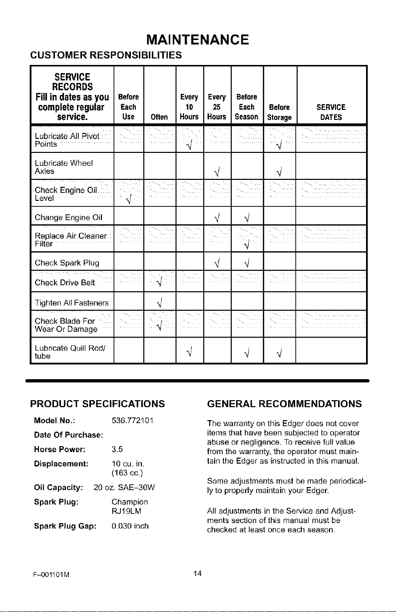
CUSTOMER RESPONSIBILITIES
SERVICE
RECORDS
Fillindatesasyou Before Every Every Before
completeregular Each 10 25 Each Before
service. Use Often Hours Hours Season Storage
I I
Lubdcate All Pivot i = I I
Points _/ ' ' ,_/ '
SERVICE
DATES
Lubricate Wheel
Axles
I
Check Engine Oil .......
Level ,_/ .....
Change Engine Oil
I t t
Replace Air Cleaner ' ' '
Filter ,_/ .
Check Spark Plug
Check Drive Belt I
Tighten Ali Fasteners
Check Blade For ' =
Wear Or Damage _t
Lubricate Quill Rod/
tube
PRODUCT SPECIFICATIONS
Model No.: 536.772101
Date Of Purchase:
Horse Power: 3.5
Displacement: 10 cu. in.
(163 cc.)
Oil Capacity: 20 oz. SAE-30W
Spark Plug: Champion
RJ19LM
Spark Plug Gap: 0.030 inch
GENERAL RECOMMENDATIONS
The warranty on this Edger does not cover
items that have been subjected to operator
abuse or negligence. To receive full value
from the warranty, the operator must main-
tain the Edger as instructed in this manual
Some adjustments must be made periodical-
ly to properly maintain your Edger.
All adjustments in the Service and Adjust-
ments section of this manual must be
checked at least once each season.
F=001101M 14
MAINTENANCE
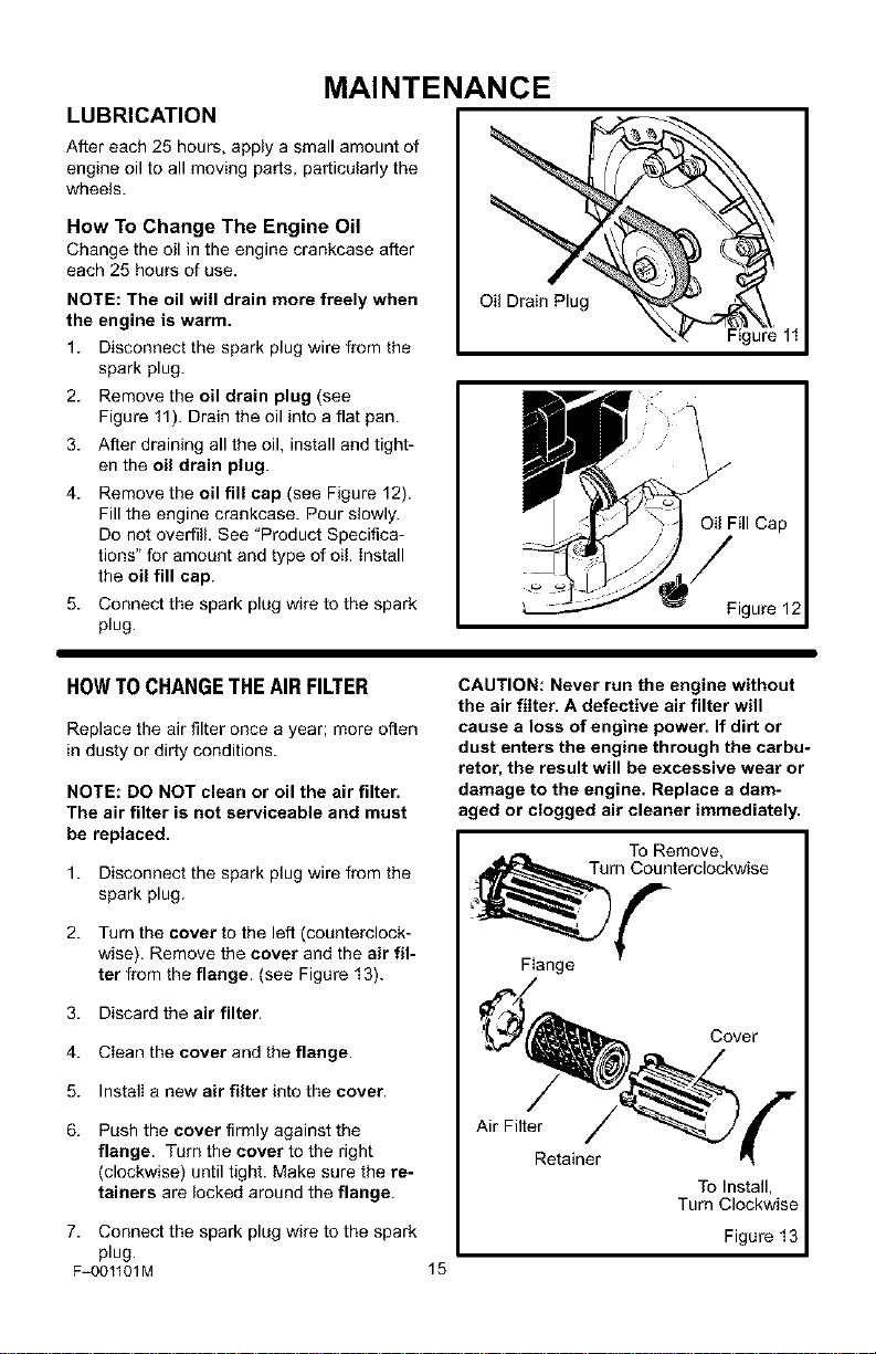
LUBRICATION
After each 25 hours, apply a small amount of
engine oil to all moving parts, particularly the
wheels.
How To Change The Engine Oil
Change the oil in the engine crankcase after
each 25 hours of use.
NOTE: The oil will drain more freely when
the engine is warm.
1. Disconnect the spark plug wire from the
spark plug.
2. Remove the oil drain plug (see
Figure 11). Drain the oil into a flat pan.
3. After draining all the oil, install and tight-
en the oil drain plug.
4. Remove the oil fill cap (see Figure 12).
Fill the engine crankcase. Pour slowly.
Do not overfill. See "Product Specifica-
tions" for amount and type of oil. install
the oil fill cap.
5. Connect the spark plug wire to the spark
plug.
Oil Drain Plug
Figure 11
Oil Fill Cap
Figure 12
HOWTOCHANGETHEAIRFILTER
Replace the air filter once a year; more often
in dusty or dirty conditions.
NOTE: DO NOT clean or oil the air filter.
The air filter is not serviceable and must
be replaced.
1. Disconnect the spark plug wire from the
spark plug.
2. Turn the cover to the left (counterclock-
wise). Remove the cover and the air fil-
ter from the flange. (see Figure 13).
3. Discard the air filter.
4. Clean the cover and the flange.
5. Install a new air filter into the cover.
6. Push the cover firmly against the
flange. Turn the cover to the right
(clockwise) until tight. Make sure the re-
tainers are locked around the flange.
CAUTION: Never run the engine without
the air filter. A defective air filter will
cause a loss of engine power. If dirt or
dust enters the engine through the carbu-
retor, the result will be excessive wear or
damage to the engine. Replace a dam-
aged or clogged air cleaner immediately.
To Remove,
Turn Counterclockwise
Flange
Cover
Air Filter
Retainer
To Install,
Turn Clockwise
7. Connect the spark plug wire to the spark Figure 13
plug.
F_001101M 15
MAINTENANCE
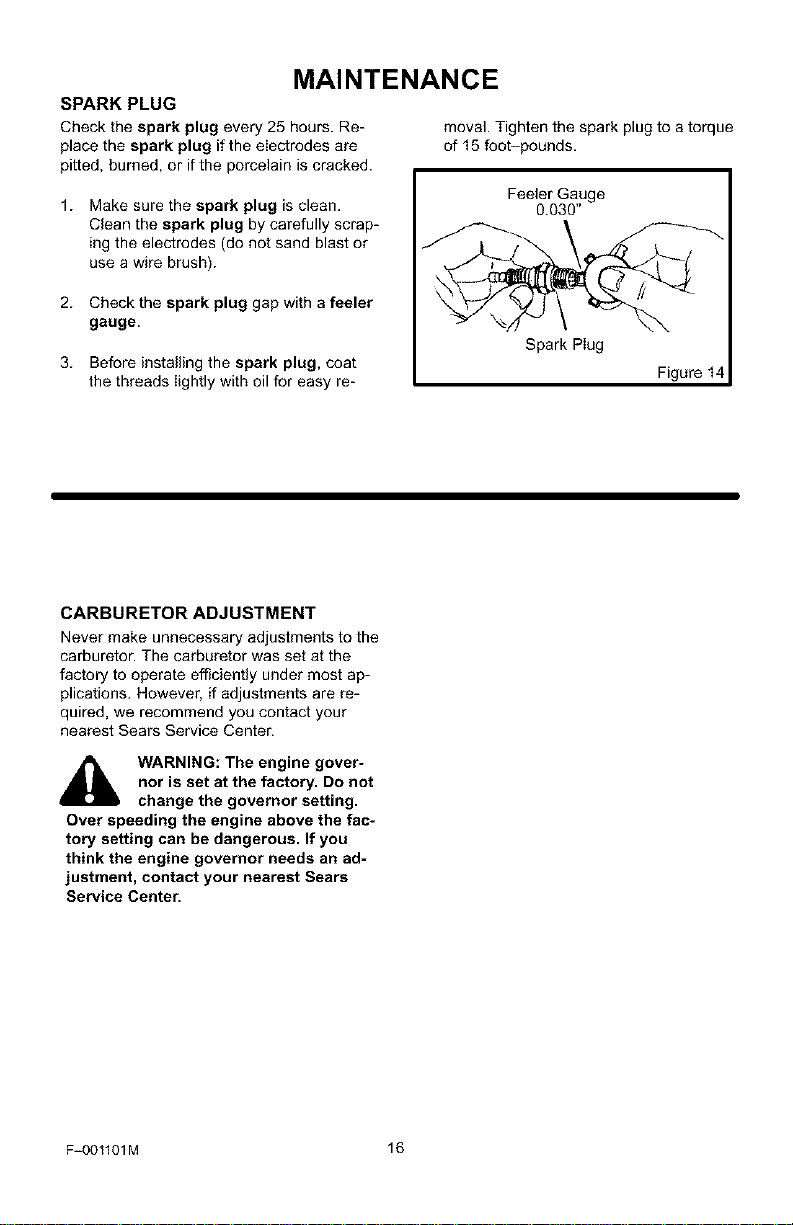
SPARK PLUG
Check the spark plug every 25 hours. Re-
place the spark plug if the electrodes are
pitted, burned, or if the porcelain is cracked.
moval. Tighten the spark plug to a torque
of 15 foot-pounds.
1. Make sure the spark plug is clean.
Clean the spark plug by carefully scrap-
ing the electrodes (do not sand blast or
use a wire brush).
2. Check the spark plug gap with a feeler
gauge.
3. Before installing the spark plug, coat
the threads Iightly with oil for easy re-
Feeler Gauge
0.030"
Spark Plug
Figure I
CARBURETOR ADJUSTMENT
Never make unnecessary adjustments to the
carburetor'. The carburetor was set at the
factory to operate efficiently under most ap-
plications. However, if adjustments are re-
quired, we recommend you contact your
nearest Sears Service Center.
WARNING: The engine gover-
nor is set at the factory. Do not
change the governor setting.
Over speeding the engine above the fac-
tory setting can be dangerous. If you
think the engine governor needs an ad-
justment, contact your nearest Sears
Service Center.
F_OO1101M 16
SERVICE AND ADJUSTMENT
HOW TO REMOVE THE BELT
The belt made of a special compound. If the
belt becomes worn or breaks, replace the
belt with an original equipment belt.
1. Disconnect the spark plug wire from the
spark plug.
2. Drain the gasoline and oil from the en-
gine.
3. Tip the Edger backwards on the handle.
Block the top of the handle against a wali
or under a bench.
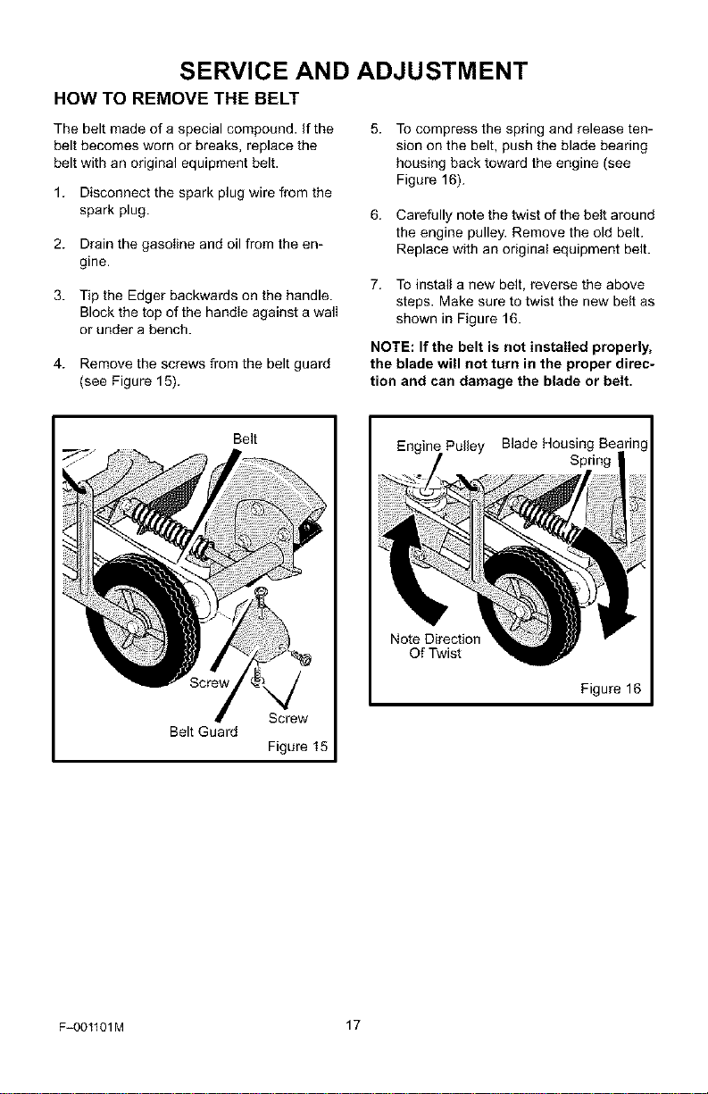
4. Remove the screws from the belt guard
(see Figure 15).
To compress the spring and release ten-
sion on the belt, push the blade bearing
housing back toward the engine (see
Figure 16).
6. Carefully note the twist of the belt around
the engine pulley. Remove the old belt.
Replace with an original equipment belt.
7. To install a new belt, reverse the above
steps. Make sure to twist the new belt as
shown in Figure 16.
NOTE: If the belt is not installed properly,
the blade will not turn in the proper direc-
tion and can damage the blade or belt.
Belt Guard
Belt
Screw
Figure 15
Pulley Blade Housing Be_
Spring
Note Direction
Qf Twist
Figure 16
F_001101M 17
SERVICE AND ADJUSTMENT
HOW TO REPLACE THE BLADE
The blade is subject to wear and damage,
such as nicks and dents. This will not gener-
ally affect its function.
The blade is designed to not require sharp-
ening. Do not attempt to sharpen the blade.
The blade is also reversible. If nicks or
dents are excessive, remove the blade and
turn it around. This will provide a fresh cut-
ting edge. Replace the blade if both sides
are worn or damaged.
1. Disconnect the spark plug wire from the
spark plug.
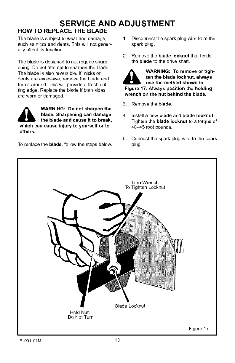
2. Remove the blade Iocknut that holds
the blade to the drive shaft.
,_ WARNING: To remove or tigh-
ten the blade Iocknut, always
use the method shown in
Figure 17. Always position the holding
wrench on the nut behind the blade.
WARNING: Do not sharpen the
blade. Sharpening can damage
the blade and cause it to break,
which can cause injury to yourself or to
others.
3. Remove the blade.
4. Install a new blade and blade Iocknut.
Tighten the blade Iocknut to a torque of
40-45 foot pounds.
To replace the blade, follow the steps below.
5. Connect the spark plug wire to the spark
plug.
Turn Wrench
To Tighten Locknut
Blade Locknut
Hold Nut,
Do Not Turn
Figure 17
F_OO1101M 18
SERVICE AND ADJUSTMENT
STORAGE
_1_ WARNING: Never store the
Edger indoors with fuel in the
fuel tank. Never store in an en-
closed, poorly ventilated area where
fumes could reach an open flame, a
spark or a pilot light as on a furnace, wa-
ter heater or clothes dryer.
_lb ARNING: Do not remove gas-
oline while inside a building,
near a fire, or while you smoke.
Gasoline fumes can cause an explosion
or a fire.
When the Edger is put in storage for thirty
days or more, follow the steps below to
make sure the Edger is in good condition the
following season.
Edger
Completely clean the Edger.
Check the Edger for worn or damaged
pads. Tighten all loose hardware.
Apply a smatI amount of engine oil to all
moving parts, particularly the wheels.
Put the Edger in a building that has good
ventilation.
Cover the Edger with a suitable protec-
tive cover that does not retain moisture.
Do not use plastic.
IMPORTANT: Never cover the Edger while
the engine and exhaust areas are still
warm.
NOTE: A yearly checkup or tune-up by a
Sears Service Center is a good way to
make sure that your Edger will provide
maximum performance for the next sea-
son.
Engine
IMPORTANT: It is important to prevent
gum deposits from forming in fuel system
parts such as the carburetor, fuel filter,
fuel hose, and tank during storage. Also,
using alcohol-blended fuels (called gaso-
hol, ethanol or methanol) can attract
moisture which leads to separation and
formation of acids during storage. Acidic
gas can damage the fuel system of an en-
gine while in storage.
To prevent engine damage when the Edger
is in storage for 30 days or more, follow the
steps below:
Let the engine run until it is out of gaso-
line.
If you do not want to remove the gaso-
line, add a fuel stabilizer to any gasoIine
Ieft in the fuel tank. A fuel stabilizer will
minimize gum deposits and acids. If the
fuel tank is almost empty, mix the fuel
stabilizer with fresh gasoline in a sepa-
rate container and add the mixture to the
fuel tank. Always follow the instructions
on the stabilizer container. Start the en-
gine. Let the engine run for 10 minutes
to allow the mixture to reach the carbu-
retor.
Change the engine oil. See "How To
Change The Engine Oil" in the Mainte-
nance section.
Lubricate the piston/cylinder area. This
can be done by first removing the spark
plug and squirting a small amount of
clean engine oil into the spark plug hole.
Then, cover the spark plug hole with a
rag to absorb oil spray. Next, rotate the
engine by pulling the starter two or three
times. Finally, install the spark plug and
attach the spark plug wire.
Store the Edger in the operating position
with the wheels down. If the Edger is
stored in any other position, oil from the
crankcase will enter the cylinder and
cause a service problem.
F-001101M 19
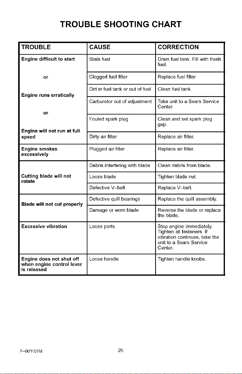
TROUBLE SHOOTING CHART
TROUBLE CAUSE
Engine difficult to start Stale fuel
or
Engine runs erratically
or
Engine will not run at full
speed
Clogged fuel filter
Dirt in fuel tank or out of fuel
Carburetor out of adjustment
Fouled spark plug
Dirty air filter
Engine smokes Plugged air filter
excessively
Clean debris from blade.
Cutting blade will not
rotate
Debris interfering with blade
Loose blade
Defective V-belt
Defective quill bearings
Damage or worn blade
CORRECTION
Drain fuel tank. Fill with fresh
fuel.
Replace fuel filter
Clean fuei tank.
Take unit to a Sears Service
Center.
Clean and set spark plug
gap.
Replace air filter.
Replace air filter.
Blade will not cut properly
Excessive vibration Loose parts Stop engine immediately.
Tighten all fasteners. If
vibration continues, take the
unit to a Sears Service
Center.
Engine does not shut off Loose handle Tighten handle knobs.
when engine control lever
is released
Tighten blade nut.
Replace V-belt.
Replace the quill assembly.
Reverse the blade or replace
the blade.
F_001101M 20
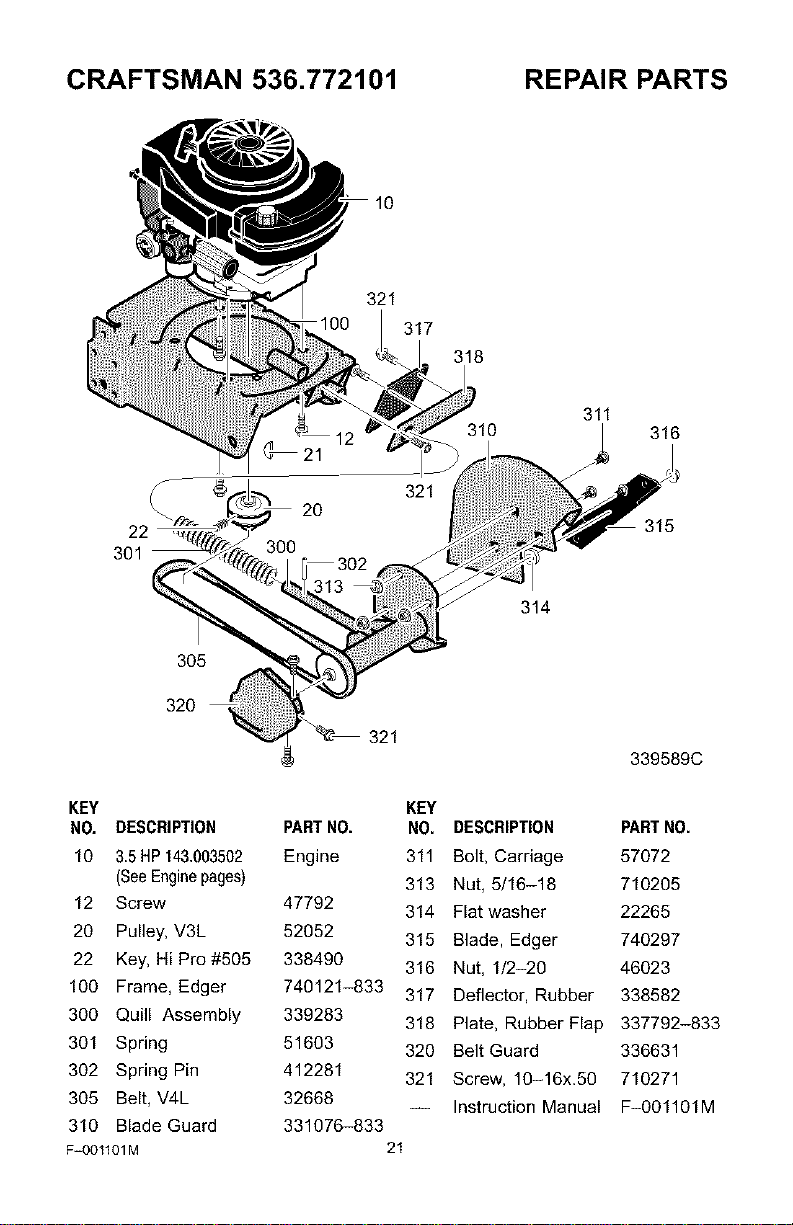
CRAFTSMAN 536.772101 REPAIR PARTS
22
301
305
320
10
321
321
317
318
311
314
316
315
339589C
KEY
NO. DESCRIPTION
10 3.5HP 143.003502
(SeeEnginepages)
12 Screw
20 Pulley, V3L
22 Key, Hi Pro #505
100 Frame, Edger
300 Quill Assembly
301 Spring
302 Spring Pin
305 Belt, V4L
310 Blade Guard
F=001101M
KEY
PARTNO. NO. DESCRIPTION PARTNO.
Engine 311 Bolt, Carriage 57072
313 Nut, 5/16-18 710205
47792 314 Flat washer 22265
52052 315 Blade, Edger 740297
338490 316 Nut, 1/2-20 46023
740121-833 317 Deflector, Rubber 338582
339283 318 Plate, Rubber Flap 337792-833
51603 320 Belt Guard 336631
412281 321 Screw, 10-16x.50 710271
32668
-- Instruction Manual F-001101M
331076-833
21
CRAFTSMAN 536.772101 REPAIR PARTS
418
412
416
420
405
415
403
423
343712C
F_OO1101M 22
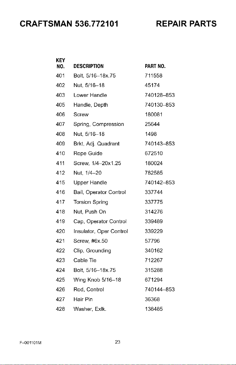
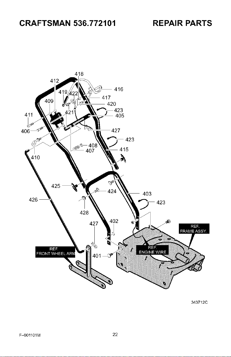
CRAFTSMAN 536.772101 REPAIR PARTS
KEY
NO. DESCRIPTION
401 Bolt, 5/16-18x.75
402 Nut, 5/16-18
403 Lower Handle
405 Handle, Depth
406 Screw
407 Spring, Compression
408 Nut, 5/16-18
409 Brkt, Adj. Quadrant
410 Rope Guide
411 Screw, 1/4-20xl.25
412 Nut, 1/4-20
415 Upper Handle
416 Bail, Operator Control
417 Torsion Spring
418 Nut, Push On
419 Cap, Operator Control
420 Insulator, Oper Control
421 Screw, #6x.50
422 Clip, Grounding
423 Cable Tie
424 Bolt, 5/16-18x.75
425 Wing Knob 5/16-18
426 Rod, Control
427 Hair Pin
428 Washer, Exlk.
PARTNO.
711558
45174
740128-853
740130-853
180081
25644
1498
740143-853
672510
180024
782585
740142-853
337744
337775
314276
339489
339229
57796
340162
712267
315288
671294
740144-853
36368
138485
F=OO1101M 23
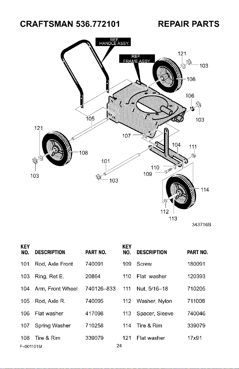
CRAFTSMAN 536.772101 REPAIR PARTS
121
106
121
103
105
110
109
103
103
111
114
112
113
343716B
KEY KEY
NO. DESCRIPTION PARTNO. NO. DESCRIPTION
101 Rod, Axle Front 740091 109 Screw
103 Ring, Ret E. 20864 110 Flat washer
104 Arm, Front Wheel 740126-833 111 Nut, 5/16-18
105 Rod, Axle R. 740095 112 Washer, Nylon
106 Flat washer 417098 113 Spacer, Sleeve
107 Spring Washer 710258 114 Tire & Rim
108 Tire & Rim 339079 121 Flat washer
F_001101M 24
PARTNO.
180091
120393
710205
711008
740046
339079
17x91
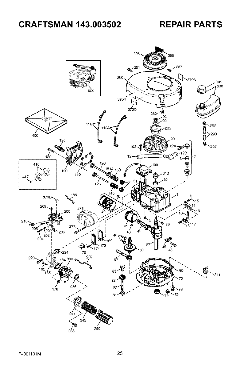
CRAFTSMAN 143.003502 REPAIR PARTS
130
416
1;
126
119
125
-12B
185
178
207
52
F-OO1101M 25
CRAFTSMAN 143.003502
KEY PART
NO. NO. DESCRIPTION
0 RPM High 3050 to 3350
0 RPM Low 2400 to 2709
27625 Oil Fill Plug
29673 Oil Fill Plug Gasket
1 37289 Cylinder (Incl. 2,20 & 150)
2 26727 Dowel Pin
6 33734 Breather Element
7 36557 Breather Ass'y.
(Incl. 6 & 12A)
12 36775 Breather Tube
12A 36558 Breather Cover & Tube
(Incl. 12B)
12B 36694 Breather Tube Eibow
14 28277 Washer
15 30589 Governor Rod (Incl. 14)
16 34839A Governor Lever
17 31335 Governor Lever Clamp
18 651018 Screw, Torx
19 36281 Extension Spring
20 32609 Oil Seal
30 36833 Crankshaft
40 35544A Piston, Pin & Ring Set (Std.)
40 35545A Piston, Pin & Ring Set
(.010" OS)
40 35546 Piston, Pin & Ring Set
(.O2O"OS)
41 35541 Piston & Pin Ass'y. (Std.)
(Incl. 43)
41 35542 Piston & Pin Ass'y.
(.010" OS) (Incl. 43)
41 35543 Piston & Pin Ass'y.
(.020" OS) (Incl. 43)
42 35547A Ring Set (Std.)
42 35548A Ring Set (.010" QS)
42 35549 Ring Set (.020 OS)
43 20381 Piston Pin Retaining Ring
REPAIR PARTS
KEY PART
NO. NO. DESCRIPTION
45 36777 Connecting Rod Ass'y.
(Incl. 46)
46 32610A Connecting Rod Boit
48 27241 Valve Lifter
50 37032 Camshaft (NCR)
52 29914 Oil Pump Ass'y.
69 35261 Mounting Flange Gasket
70 326120 Mounting Flange
(Incl. 72 thru 83)
72 36083 Oil Drain Plug
75 27897 Oil Seal
80 30574A Governor Shaft
81 30590A Washer
82 30591 Governor Gear Ass'y.
(Incl. 81)
83 30588A Governor Spool
86 650488 Screw, 1/4-20 x 1-1/4"
89 610961 Flywheel Key
90 611213 Flywheel
92 650815 Belleville Washer
93 650816 Flywheel Nut
109 34443B Solid State Ignition
103 651007 Screw, Torx T-15
119 36230 Ground Wire
110A 36816 Ground Wire
119 37028 Cylinder Head Gasket
129 36825 Cylinder Head
125 37288 Exhaust Valve (Std.)
(Incl. 151)
126 37289 Intake Valve (Std.)
(Incl. 151)
139 6021A Screw, 5/16-18 x 1-1/2"
135 35395 Resistor Spark Plug
(RJ19LM)
150 31672 Valve Spring
F-OO1101M 26
CRAFTSMAN 143.003502
151 31673 Valve Spring Cap
151A 40017 Intake Valve Seal
169 36783 Valve Cover Gasket
172 36784 Valve Cover
174 30200 Screw, 10-24 x 9/16"
178 29752 Nut & Lock Washer
179 30593 Retainer Clip
182 6201 Screw, 1/4-28 x 7/8"
184 26756 Carburetor To Intake Pipe
Gasket
185 36785 Intake Pipe
186 34337 Governor Link
200 33205A Control Bracket
(incl. 202 thru 206)
202 36482 Compression Spring
203 31342 Compression Spring
204 651029 Screw, Torx T-10
205 651019 Screw, Torx T-10
206 610973 Terminal
207 34336 Throttle Link
209 30200 Screw, 10-24 x 9/16"
215 32410 Control Knob
223 650451 Screw, 1/4-20 x I"
224 36786 Intake Pipe Gasket
238 650932 Screw, 10-32 x 49/64"
239 34338 Air Cleaner Gasket
241 35797 Air Cleaner Collar
245 35066 Air Cleaner Filter
250 35065 Air Cleaner Cover
260 36834 Blower Housing
261 30200 Screw, 10-24 x 9/16"
262 650831 Screw, 1/4-20 x 1/2"
REPAIR PARTS
275 36790A Muffler
277 650988 Screw, 1/4-20 x 2-5/16"
285 35000A Starter Cup
287 650926 Screw, 8-32 x 21/64"
290 34357 Fuel Line
292 26460 Fuel Line Clamp
300 35586 Fuel Tank (Incl. 292 & 301)
301 35355 Fuel Cap
311 27625 Oil Fill Plug Ass'y
313 34080 Spacer
355 590701 Starter Handle (Black)
370A 36261 Lubrication Decal
370B 35169 Control Decal
370C 37318 Primer Decal 3 X)
370R 37317 Warning Decal
380 640262 Carburetor(Incl. 184)
390 590737 Rewind Starter (NOTE:
This engine could have
been built with 590694
starter).
400 37029A Gasket Set (ind. Items
Marked PK in Notes)
Incl. Part #'s 26756
(1),28833 (1), 34338 (1),
35261 (1), 36783 (1),
36786 (1), 37028 (1),
36832 (1), 36996 (1)
416 36085 Spark Arrestor Kit
(Incl. 417) (Optional)
417 650821 Screw, 10-32 x 1/2"
(Optional)
900 0 Replacement Engine
NONE, order from 71-999
900 0 Replacement S/B 750831,
order from 71-999
F-OO1101M 27
CRAFTSMAN 143.003502 REPAIR PARTS
(_\20A
16
F-OO1101M 28
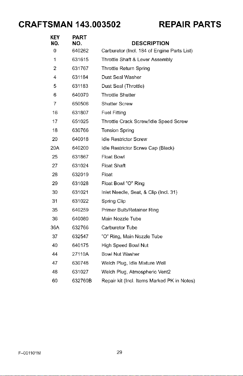
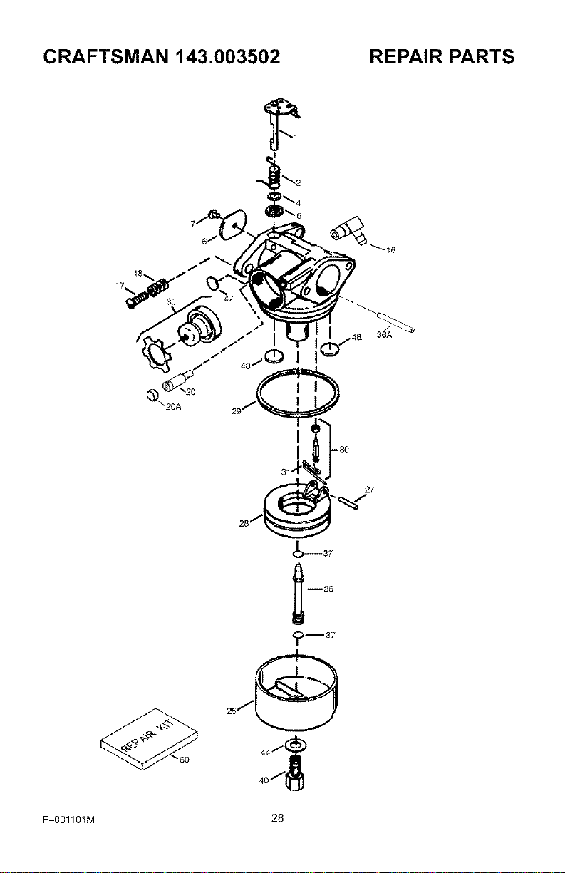
CRAFTSMAN 143.003502 REPAIR PARTS
KEY PART
N0. NO.
0 640262
1 631615
2 631767
4 631184
5 631183
6 640070
7 650506
16 631807
17 651025
18 630766
20 640018
20A 640200
25 631867
27 631024
28 632019
29 631028
30 631021
31 631022
35 640259
36 640080
36A 632766
37 632547
40 640175
44 27110A
47 630748
48 631027
60 632760B
DESCRIPTION
Carburetor (Incl. 184 of Engine Parts List)
Throttle Shaft & Lever Assembly
Throttle Return Spring
Dust Seal Washer
Dust Seal (Throttle)
Throttle Shutter
Shutter Screw
Fuel Fitting
Throttle Crack Screw/Idle Speed Screw
Tension Spring
Idle Restrictor Screw
Idle Restrictor Scrwe Cap (Black)
Float Bowl
Float Shaft
Float
Float Bowl "O" Ring
Inlet Needle, Seat, & Clip (Incl. 31)
Spring Clip
Primer Bulb/Retainer Ring
Main Nozzle Tube
Carburetor Tube
"O" Ring, Main Nozzle Tube
High Speed Bowl Nut
Bowl Nut Washer
Welch Plug, Idle Mixture Well
Welch Plug, Atmospheric Vent2
Repair kit (Incl. Items Marked PK in Notes)
F-001101M 29
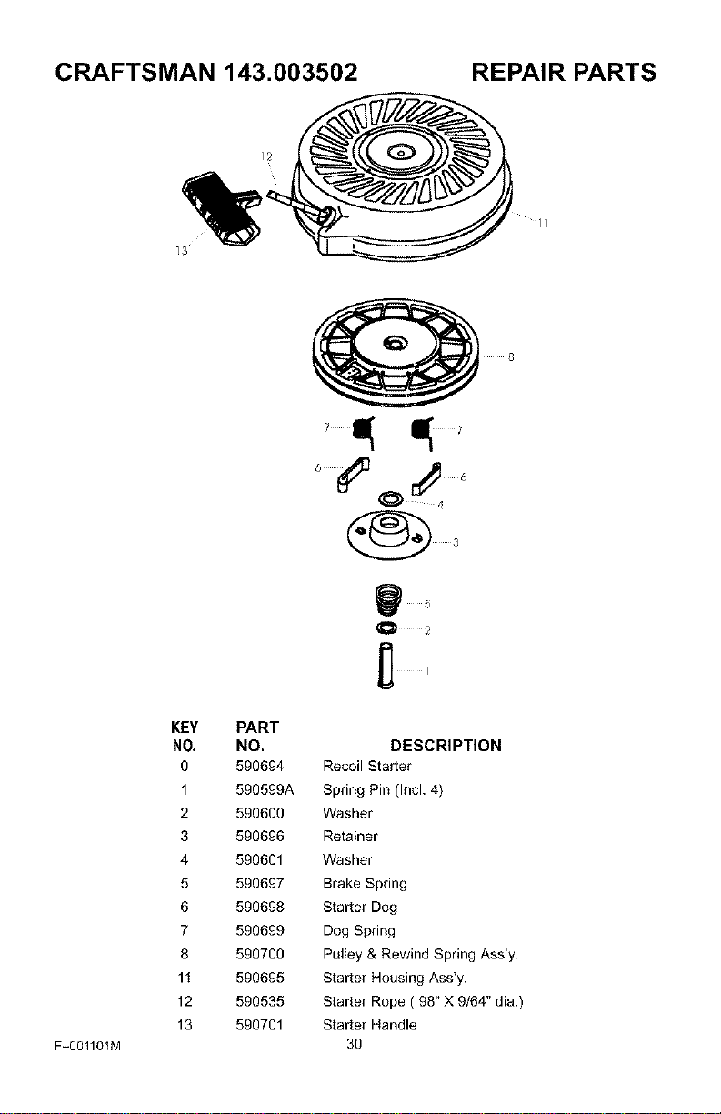
CRAFTSMAN 143.003502 REPAIR PARTS
]2
_3
]]
F-001101M
KEY PART
NO, NO.
0 590694
1 590599A
2 590600
3 590696
4 590601
5 590697
6 590698
7 590699
8 590700
11 590695
12 590535
13 590701
8
3
DESCRIPTION
Recoil Starter
Spring Pin (Incl. 4)
Washer
Retainer
Washer
Brake Spring
Starter Dog
Dog Spring
Pulley & Rewind Spring Ass'y.
Starter Housing Ass'y.
Starter Rope ( 98" X 9/64" dia.)
Starter Handle
3O
For the repair or replacement parts you
need delivered directly to your home
Call 7am-7pm, 7days a week
1-800-366-PART
(1-800-366-7278)
Para ordenar piezas con entrega
a domicilio - 1-800-859-7084
For in-house major brand repair service
Call 24 hours a day, 7days a week
1-800-4-REPAIR
(1-800-473-7247)
Para pedir servicio de reparacibn a
domicilio- 1-800-676-5811
For the location of a Sears Parts and
Repair Center in your area
Call 24 hours a day, 7days a week
1-800-488-1222
gggggg
For information on purchasing a Sears
Maintenance agreement or to inquire
about an existing Agreement
Call 9am-5pm, Monday-Saturday
1-800-827-6655
When requesting service or ordering
parts, always provide the following infor-
mation:
• Product Type • Part Number
• Model Number • Part Description
America'sRepairSpecialists
Printed in U.S.A.