
Safety • AssembJy • Operation • Adjustment • Maintenance • TroubJeshooting • Warranty
A OR'S MANUAL
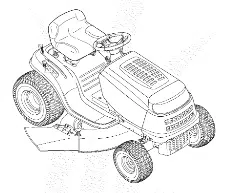
Shift-On-The-Go TM Lawn Tractor -- Models 760=779
iMPORTANT
READ SAFETY RULES AND iNSTRUCTiONS CAREFULLY BEFORE OPERATION
Warning: This unit is equippedwithan internalcombustionengineandshouldnot beusedon or nearany unimprovedforest-covered,brush-
coveredor grass-coveredland unlessthe engine'sexhaustsystemis equippedwitha sparkarrestermeetingapplicablelocalorstate laws(if any).
If a sparkarresteris used,it shouldbemaintainedineffectiveworkingorder by the operator.Inthe Stateof Californiathe aboveis requiredbylaw
(Section4442of the CaliforniaPublicResourcesCode). Otherstates mayhavesimilarlaws.Federallaws applyonfederallands.A sparkarrester
for the muffleris availablethroughyournearestengineauthorizedservicedealeror contactthe servicedepartment,RO. Box361131Cleveland,
Ohio44136-0019.
FORMNO.769-01598C
PRINTEDIN U.S.A. MTD LLC, P.O. BOX 361131 CLEVELAND, OHiO 44136=0019 01/22/2007

This Operator's Manual is an important part of your new lawn tractor, it will help you assemble,
prepare and maintain the unit for best performance. Please read and understand what it says.
Table of Contents
Slope Gauge ........................................................ 3
Safe Operation Practices ................................... 4
Setting UpYour Lawn Tractor ............................ 8
Operating Your Lawn Tractor ........................... 12
Adjusting Your Lawn Tractor ............................ 20
Maintaining Your Lawn Tractor ........................ 22
Off=Season Storage / Attachments ................. 28
Safety Labels .................................................... 29
Trouble Shooting .............................................. 30
Warranty .............................................. Back Page
Finding and Recording Model Number
BEFOREYOU STARTASSEMBLING YOURNEW EQUIPMENT,
please locatethe model plate on the equipment and copy the
informationto the sample model plate provided to the right. You
can locate the model plate by looking beneaththe seat.
This information will be necessary to use the manufacturer's web
site and/or obtain assistance from the Customer Support Depart-
ment or an authorized service dealer.
Model Number
www,mtdproducts.com
Serial Number
MTD LLC
P.O. BOX 361131
CLEVELAND, OH 44136
330=220=4683
800=800=731 0
n_
Customer Support
Please do NOTreturn the unit to the retailer from which it was
purchased, without first contacting Customer Support.
ifyou have difficulty assembling this product or have any questions regardingthe controls, operation, or maintenanceof this
unit, you can seek help from the experts. Choose from the options below:
1. Visit www.mtdproducts.com.
2. Phonea Customer Support Representative at 1 (800) 800-7310.
3. The engine manufacturer is responsiblefor all engine-related issues with regardsto performance, power-rating,specifica-
tions, warranty and service. Please refer to the engine manufacturer'sOwner's/Operator's Manual, packed separatelywith
your unit.

lyUsethispageasa guidetodetermineslopeswhereyoumaynotoperatesafe . .....
U
Do not operate your hwn mower on such slopes.
!
!
!
!
!
t
C_L
o
C'D
<
<
dD
CD
WARNING
Do not mowon inclines
with a slope in excess
of 15degrees (a rise
of approximately2-1/2
feet every 10feet). A
riding mower could
overturn and cause
serious injury.
Operate riding mowers
up and down slopes,
never across the face
of slopes.
\
3
/ ,j_ WARNING: Engine Exhaust,some of its constituents, and certain vehicle compo-
L A_k nents contain or emit chemicals knownto State of Californiato cause cancer and
birth defects or other reproductiveharm.
Ii i i
DANGER: This machine was built to be operated according to the rules for safe operation in this
manual. As with any type of power equipment, carelessness or error on the part of the operator can
Safe result in serious injury. This machine is capable of amputating hands and feet and throwing objects.
i
- = Failureto observe the following safety instructions could result in serious injury or death.
operation
=
Practices Children Operation
1. Tragicaccidentscan occurif the operatoris not Safe Handling of Gasoline:
alert tothe presenceof children.Childrenare often
attractedto the machineandthe mowingactivity. 1. Toavoid personalinjuryor propertydamageuse
Theydo not understandthe dangers.Neverassume extremecare inhandlinggasoline. Gasolineis
thatchildrenwill remainwhereyou last sawthem. extremelyflammableand the vapors areexplo-
sive. Seriouspersonalinjurycanoccur whengasoline
a. Keepchildrenout of the mowingareaandin is spilledon yourselfor yourclotheswhichcan ignite.
watchfulcare of a responsibleadult otherthan Washyourskin andchangeclothesimmediately.
the operator.
b. Bealert andturn machineoff if a childenters a. Use onlyan approvedgasolinecontainer.
b. Neverfill containersinsidea vehicleor ona
the area.
truckor trailerbed witha plasticliner.Always
WARN IN G c. Beforeand while backing,lookbehindand
placecontainerson the groundawayfrom
downfor smallchildren.
yourvehiclebeforefilling.
. . d. Nevercarrychildren,evenwiththe blade(s)
This symbol points c. When practical,removegas-powered
. shutoff.They mayfalloff andbeseriously equipmentfromthe truck ortrailerand refuelit
out mportant safety injuredor interferewith safemachineoperation.
nstruct!0nswhich, !f onthe ground.Ifthis is notpossible,then
..... e. Useextremecarewhenapproachingblind refuelsuch equipmentona trailerwith a
i /
not followed, could corners,doorways,shrubs,trees or other portablecontainer,ratherthan from agasoline
objectsthat mayblockyourvisionof a child dispensernozzle.
endanger the personal who mayruninto the machine, d. Keepthe nozzlein contactwith the rimof
safety and!or property f. To avoid back-overaccidents, always
the fueltank or containeropeningat all
of yoursef and others, disengage the cutting blade(s) before timesuntilfuelingis complete.Donot usea
Read and follow all shiftinginto Reverse. If equipped, the nozzlelock-opendevice.
"Reverse Caution Mode" should not be e. Extinguishallcigarettes,cigars,pipesand
instructions in this man- used when childrenor othersare around.
othersourcesof ignition.
ual before attempt ngto g. Keepchildrenawayfromhotor running f. Neverfuel machineindoors.
operate this machine; engines.Theycansufferburnsfroma hot
. . muffler, g. Neverremovegas cap oraddfuel whilethe
engineis hot or running.Allowengineto cool
Failure to comply with h. Removekeywhen machineis unattendedto at leasttwominutesbeforerefueling.
these instructions may preventunauthorizedoperation.
. . . h. Neveroverfill fuel tank.Fill tankto no more
result In personal Injury, 2. Neverallowchildrenunder 14yearsoldto operate
. thanYzinchbelowbottomof filler neckto
When you see this the machine.Children14years oldandovershould allowspacefor fuel expansion.
symbol, readandunderstandthe operationinstructionsand
safetyrules inthis manualandshouldbetrainedand i. Replacegasolinecapandtightensecurely.
HEED iTS WARNING supervisedbya parent, j. If gasolineis spilled,wipe it offthe engine
andequipment.Moveunitto anotherarea.
l
Wait5 minutesbeforestartingthe engine.
k. To reducefire hazards,keepmachinefreeof
You r
grass,leaves,or other debrisbuild-up.Clean
Responsibility upoil orfuel spillageand removeany fuel
soakeddebris.
Restrictthe use I. Neverstorethe machineor fuel container
of th s power roachne insidewherethere is an openflame,spark
to persons who read, or pilotlightas on awaterheater,space
n'erstand heater,furnace,clothesdryeror othergas
U Cl , appliances.
and follow the warnings . . .
m. Allowa machineto cool at leastfiveminutes
and instructions beforestoring.
n th_smanual
4
.
General Operation: 14.Watchfor traffic whenoperattngnearor crossmg
1. Read,understand,andfollowall instructionsonthe roadways.Thismachineis not intendedfor useon
machineandinthe manual(s)beforeattemptingto
assembleandoperate.Keepthis manualin a safe
placefor futureand regularreferenceand forordering
replacementparts.
2. Befamiliarwithall controlsand theirproperoperation.
Knowhow to stopthe machineanddisengagethem
quickly.
3. Neverallowchildrenunder14yearsold to operate
this machine.Children14yearsold andovershould
readandunderstandthe operationinstructionsand
safetyrulesin this manualandshouldbetrainedand
supervisedby aparent.
4. Neverallowadults to operatethis machinewithout
properinstruction.
5. To helpavoid bladecontactora thrownobjectinjury,
keepbystanders,helpers,childrenand petsat least
75 feetfrom the machinewhileit is in operation.Stop
machineif anyoneentersthe area.
6. Thoroughlyinspecttheareawherethe equipmentis to
beused.Removeall stones,sticks,wire,bones,toys,
andotherforeignobjectswhichcould bepickedup
andthrownbythe blade(s).Thrownobjectscancause
seriouspersonalinjury.
7. Planyourmowingpatternto avoiddischargeof
materialtowardroads,sidewalks,bystandersandthe
like.Also,avoiddischargingmaterialagainsta wall or
obstructionwhichmaycausedischargedmaterialto
ricochetbacktowardthe operator.
8. Alwayswearsafety glassesor safetygogglesduring
operationand while performingan adjustmentor
repairto protectyour eyes.Thrownobjectswhich
ricochetcan causeseriousinjuryto the eyes.
9. Wearsturdy,rough-soledworkshoes and close-fitting
slacksandshirts. Loosefittingclothesandjewelry
can becaughtin movableparts.Neveroperatethis
machinein barefeet or sandals.
10.Beawareof the mowerand attachmentdischarge
directionanddo notpoint it at anyone.Do notoperate
the mowerwithoutthe dischargecoverorentiregrass
catcherin itsproperplace.
11.Do notput handsor feet near rotatingpartsor under
the cuttingdeck.Contactwiththe blade(s)can
amputatehandsandfeet.
12.Amissingor damageddischargecovercan cause
bladecontactor thrownobject injuries.
13.Stoptheblade(s)whencrossinggraveldrives,walks,
or roadsandwhilenot cuttinggrass.
anypublic roadway.
15.Do notoperatethe machinewhileunderthe influ-
enceof alcoholordrugs.
16.Mowonly in daylightor goodartificiallight.
17.Nevercarrypassengers.
18.Disengageblade(s)beforeshiftinginto reverse.
Backupslowly.Alwayslookdownandbehindbefore
andwhilebackingto avoida back-overaccident.
19.Slowdownbeforeturning.Operatethe machine
smoothly.Avoiderraticoperationand excessive
speed. Practices
20.Disengageblade(s),setparkingbrake,stopengine
andwaituntilthe blade(s)cometo acompletestop
beforeremovinggrasscatcher,emptyinggrass,
uncloggingchute,removingany grassor debris,or
makinganyadjustments.
21.Neverleavea runningmachineunattended.Always
turnoff blade(s),placetransmissionin neutral,set
parkingbrake,stop engineand removekey before
dismounting.
22.Useextracare whenloadingor unloadingthe
machineintoa traileror truck.Thisunitshould not
bedrivenupor downramp(s),becausethe unit
couldtip over,causingseriouspersonalinjury.The
unit mustbe pushedmanuallyon ramp(s)to loador
unloadproperly.
23.Mufflerandenginebecomehotandcan causea
burn.Do nottouch.
24.Checkoverheadclearancescarefullybeforedriving
underlowhangingtreebranches,wires,door open-
ingsetc., wheretheoperatormaybe struckor pulled
fromthe unit,whichcouldresultin seriousinjury.
25.Disengageallattachmentclutches,depressthe
brakepedalcompletelyand shift into neutralbefore
attemptingto startengine.
26.Yourmachineis designedto cut normalresidential
grassof aheightno morethan 10".Do notattemptto
mowthroughunusuallytall, dry grass(e.g.,pasture)
or pilesof dry leaves.Dry grassor leavesmay
contactthe engineexhaustand/orbuildup onthe
mowerdeckpresentinga potentialfire hazard.
27.Useonlyaccessoriesandattachmentsapprovedfor
thismachineby the machinemanufacturer.Read,
understandandfollowall instructionsprovidedwith
the approvedaccessoryor attachment.
28.Dataindicatesthat operators,age 60 yearsand
above,areinvolvedin a largepercentageof riding
mower-relatedinjuries.Theseoperatorsshould
evaluatetheirability to operatetheridingmower
seriousinjury.
29.If situationsoccur whicharenot coveredinthis
manual,usecareandgood judgment.Contactyour
customerservicerepresentativefor assistance.
__ i_i_i_iii_iiiii_ii_i_
WARNING
This symbol points
out important safety
instructions which, if
not followed, could
endanger the personal
safety and/or property
of yourselfand others.
Readand follow all
instructions in this man-
ual before attempting to
operatethis machine.
Failureto comply with
these instructionsmay
'esult in personal injury.
When you see this
symbol.
HEED iTS WARNING
Your
safelyenoughto protectthemselvesandothersfrom
Responsibility
Restricl the use
d this power machine
to personswho read.
understand
and follow the warnings
and instructions
in this manual
\
5
l i
l i i i
i i i i
Safe
Operation
Practices
out mportantsafety
_nstruct!onswhich, !f
not followed, could
endanger the personal
safety and!or property
of yourself and othersl
Read and fol!ow a!l
instruct ons in this man'
ual beforeattempting to
operate th_smachine:
oc iy
Fa!luret omP w!th
these instructions may
jeSUit inpersonal injury,
When you see this
symbol,
HEED ITS WARNING
l
¥
OUr
l
Responslbd_ty
Restnctthe use
of th s power roachne
to persons who read,
understand
Slopesarea majorfactorrelatedto lossof controland
tip-overaccidentswhichcan resultin severeinjury or
death.All slopesrequireextracaution.If you cannot
backupthe slopeor if youfeel uneasyon it, do notmow
it.
Foryour safety,usethe slopegaugeincludedas partof
thismanualto measureslopesbeforeoperatingthis unit
ona slopedor hillyarea.If the slopeis greaterthan 15
degreesas shownonthe slopegauge,do notoperate
thisunit onthat areaorserious injurycouldresult.
Do:
1. Mow upand downslopes,notacross.Exercise
extremecautionwhenchangingdirectiononslopes.
2. Watchfor holes,ruts,bumps,rocks,or other hidden
objects.Uneventerraincouldoverturnthe machine.
Tallgrasscan hide obstacles.
3. Use slowspeed.Choosea low enoughspeed
settingso that youwill not haveto stop orshift while
onthe slope.Tiresmay losetractiononslopeseven
thoughthe brakesare functioningproperly.Always
keepmachinein gearwhengoingdownslopes to
takeadvantageof engine brakingaction.
4. Followthe manufacturer'srecommendationsfor
wheelweightsor counterweightsto improvestability.
5. Use extracarewithgrasscatchersor otherat-
tachments.Thesecanchangethe stabilityof the
machine.
6. Keepall movementon theslopes slow andgradual.
Do not makesuddenchangesin speedor direction.
Rapidengagementor brakingcouldcausethe front
of the machineto liftand rapidlyflip overbackwards
whichcouldcause seriousinjury.
7. Avoidstartingor stoppingon a slope.If tires lose
traction,disengagethe blade(s)andproceedslowly
straightdownthe slope.
Do Not:
1. Do notturn on slopes unlessnecessary;then,turn
slowlyand graduallydownhill,if possible.
2. Do not mownear drop-otis,ditchesor embankments.
The mowercouldsuddenlyturnoverif awheel is over
the edgeof acliff, ditch,or if anedgecavesin.
3. Do nottry to stabilizethe machineby puttingyourfoot
onthe ground.
4. Do not usea grasscatcheron steep slopes.
5. Do not mowon wetgrass.Reducedtractioncould
causesliding.
6. Do notshift to neutralandcoastdownhill.Over-speed-
ingmaycausethe operatorto lose controlof the
machineresultingin seriousinjuryordeath.
7. Do nottow heavypullbehindattachments(e.g.loaded
dumpcart, lawnroller,etc.)on slopesgreaterthan
5 degrees.Whengoingdown hill,the extraweight
tendsto pushthetractorand maycauseyou to loose
control.(e.g.tractormayspeedup, brakingand steer-
ingabilityare reduced,attachmentmayjack-knifeand
causetractorto overturn).
Towing:
1. Towonlywith a machinethathasa hitchdesignedfor
towing.Do not attachtowedequipmentexceptat the
hitchpoint.
2. Followthe manufacturersrecommendationforweight
limitsfor towedequipmentand towingonslopes.
3. Neverallowchildrenor othersin or on towedequip-
ment.
4. On slopes,theweightof thetowedequipmentmay
causelossof tractionandlossof control.
5. Travelslowlyandallowextradistanceto stop.
6. Do notshift to neutralandcoastdownhill.
6
Service
1. Neverrun an engineindoorsor ina poorlyventilated
area. Engineexhaustcontainscarbonmonoxide,an
odorless,anddeadlygas.
2. Beforecleaning,repairing,or inspecting,makecertain
the blade(s)and all movingparts havestopped.
Disconnectthe sparkplugwireandgroundagainstthe
engineto preventunintendedstarting.
3. Periodicallycheckto make surethe bladescome to
completestopwithinapproximately(5) fiveseconds
afteroperatingthe bladedisengagementcontrol.Ifthe
bladesdo notstopwithin thethis timeframe,your unit
shouldbe servicedprofessionallyby an authorized
MTDServiceDealer.
4. Checkbrakeoperationfrequentlyas it is subjectedto
wearduring normaloperation.Adjustandserviceas
required.
5. Checkthe blade(s)andenginemountingboltsat
frequentintervalsfor propertightness.Also,visually
inspectblade(s)for damage(e.g.,excessivewear,
bent,cracked). Replacethe blade(s)with theoriginal
equipmentmanufacturer's(O.E.M.)blade(s)only,
listedin this manual."Useof parts whichdonot meet
the originalequipmentspecificationsmayleadto
improperperformanceandcompromisesafety!"
6. Mowerbladesare sharp.Wrapthe bladeor wear
gloves,and useextra cautionwhenservicingthem.
7. Keepall nuts,bolts,andscrewstight to besurethe
equipmentis insafeworkingcondition.
8. Nevertamperwiththe safetyinterlocksystemor other
safetydevices.Checktheir properoperationregularly.
9. After strikinga foreignobject,stopthe engine,
disconnectthe sparkplugwire(s)and groundagainst
the engine.Thoroughlyinspectthe machinefor any
damage.Repairthe damagebeforestartingand
operating.
10.Neverattemptto makeadjustmentsor repairsto the
machinewhile theengine is running.
11.Grasscatchercomponentsand the discharge
coveraresubjectto wearand damagewhichcould
exposemovingpartsor allowobjectsto bethrown.
Forsafety protection,frequentlycheckcomponents
andreplaceimmediatelywithoriginalequipment
manufacturer's(O.E.M.)parts only,listedinthis
manual."Useof partswhichdo notmeet theoriginal
equipmentspecificationsmayleadto improper
performanceandcompromisesafety!"
12.Do notchangethe enginegovernorsettingsor
over-speedthe engine.The governorcontrolsthe
maximumsafeoperatingspeedof theengine.
13.Maintainor replacesafety andinstructionlabels,as
necessary.
14.Observeproperdisposallawsandregulationsfor
gas,oil,etc. to protecttheenvironment.
This symbol points
out important safety
instructions which, if
not followed, could
endanger the personal
safety and/or property
of yourself and others,
Read and follow all
instructions in this man-
ual before attempting to
operatethis machine.
Failureto comply with
these instructions may
result in personal injury.
When you see this
sym3ol.
H EED iTS WARNING
li
li
\
7
Your
Responsibility
Restrictthe use
of this power machine
to persons who read.
understand
and follow the warnings
and instructions
in this manual

f _ NOTE:This OperatorsManualcoversa rangeof product
r ......
[ _ _ I RubberBoot I i j specfcatonsforvarousmodes Characterst csandfea-
, i ',
"--'E J <_ i turesdiscussedand/orillustratedin this manualmay not
J 'i:__!_i'i':,;. _b_ i beapplicableto all models.MTDLLC reservesthe right
// "_I_i_ !_ \', to changeproduct specificationsdesignsandequipment
;, _'-_ ,= -! :J!_: _ wthoutnotceand wthout ncurrng ob gaton
etll:lnCl UD .::..... 'o .....i,
v -- / _::, i " Attaching the Battery Cables
I : I . .
YOU_' LSW_ , I_,: , NOTE Somemodesareshppedwththebatterycabes
I ::: }
, I i_i:: '@ alreadyconnected.
| r'SC'_O r ' NOTE:The positivebatteryterminalis markedPos. (+).
The negativebatteryterminalis markedNeg. (-).
....
', ', • The post ve cabe (heavyredw re) s securedto the
" ' post ve batterytermna (+)wth a hexbot andhex
, nut at thefactory.Makecertainthatthe rubberboot
coversthe terminalto helpprotectit fromcorrosion.
WARNING
Use extreme care
when handling
gasoline. Gasoline is
extremely flammable
and the vapors are
;exp!osive:Never fuel
machine indoors
or While the engine
is hot or running.
Extinguishcgarettes,
cigars, pipes, and
other sources of
_gnJt on. ;
/
l
Removethehex bolt and hexnut from the negative
cable.
Removetheblack plasticcover,if present,from the
negativebatteryterminaland attachthe negative
cable(heavyblack wire)to the negativebattery
terminal(-) with the boltand nut.
NOTE:If the batteryis putinto serviceafter the date
shownontop/sideof battery,chargethe batteryas
instructedin the MaintainingYourLawnTractorsectionof
thismanualprior to operatingthe tractor.
Gas and Oil Fill-up
The gasolinetank is locatedunderthe hoodandhasa
capacityof 1-1/2gallons. Do notoverfill.
,_ WARNING:Use extreme care when
handling gasoline. Gasoline is extremely
flammable and the vapors are explosive.
Neverfuel machine indoors or while the
engine is hot or running. Extinguish ciga-
rettes, cigars, pipes, and other sources of
ignition.
Servicethe enginewithgasolineand oil as instructedin
the separateEngineOperator/OwnerManualpackedwith
yourtractor.Readinstructionscarefully.NOTE: This Operators
Manual covers a range
.... IMPORTANT:Yourtractoris shippedwith motoroil in the
of product specifications engine.However,you MUSTcheckthe oil levelbefore
i
for various models: operating.Becarefulnotto overfill.
Characteristicsand
. Shipping Brace Removal
features d scussed
and/or' ustrated 'n _ WARNING:Makesure the riding mower's
engine is off, remove the ignition key,and
th's manua may not be
applicab e to al! model& set the parkingbrakebefore removing the
shipping brace,
MTD LLC reservesthe
right to change product
Specif!cationsldesigns
and equipment without
notice and without incur-
obligation.,
ring
8
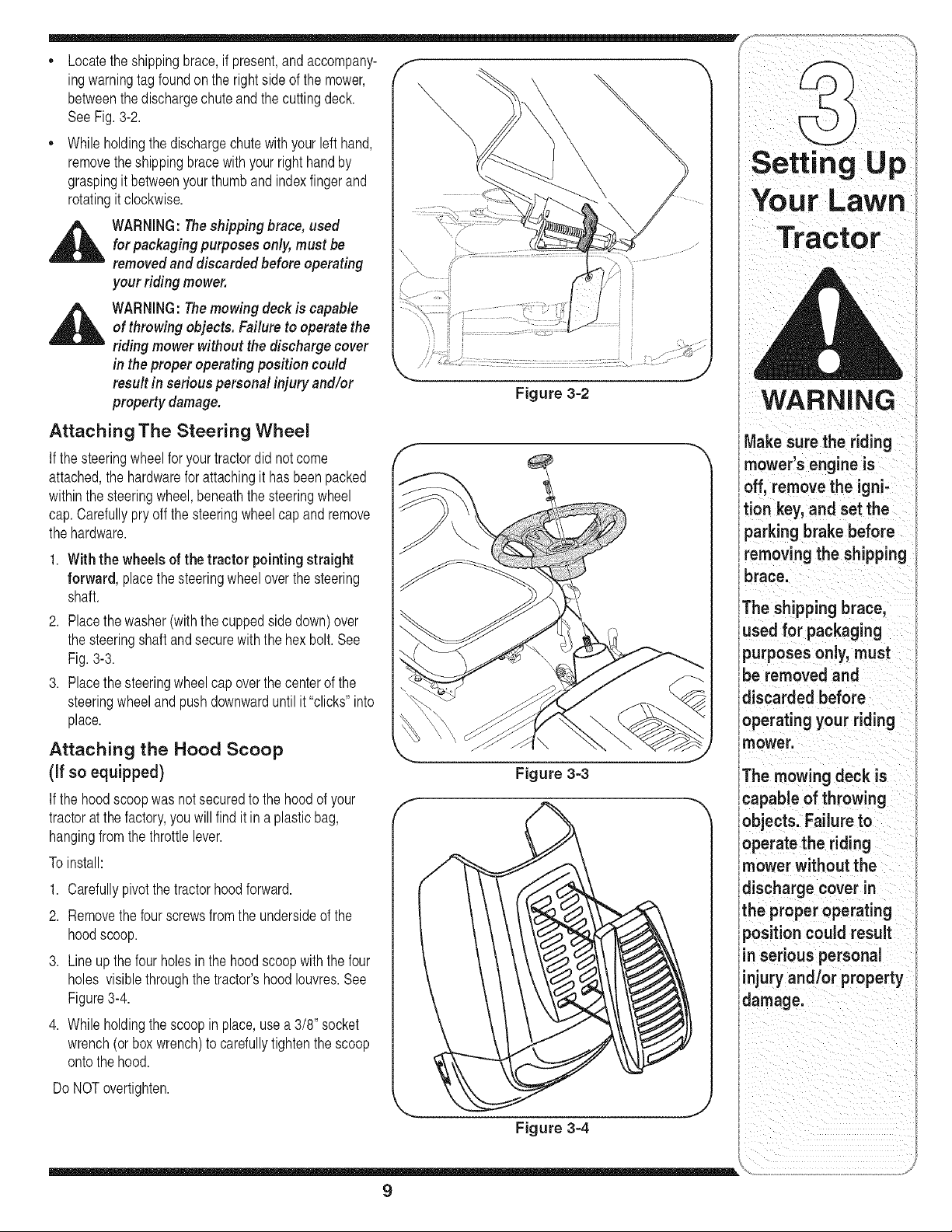
• Locatethe shippingbrace,if present,andaccompany- f-
ingwarningtagfoundon the rightside of the mower,
betweenthe dischargechuteandthe cuttingdeck.
SeeFig.3-2.
,, While holdingthe dischargechutewith yourleft hand,
removetheshippingbracewithyourright handby
graspingit betweenyourthumband indexfingerand
rotatingit clockwise.
,_ WARNING:The shipping brace, used
for packaging purposes only, must be
removed and discarded before operating
your riding mower.
_ WARNING:The mowing deck is capable
of throwing objects. Failure to operate the
riding mower without the discharge cover
in the proper operating position could
result in serious personal injury and/or
property damage.
Figure 3=2
WARNING
Attaching The Steering Wheel
If the steeringwheelfor yourtractordid notcome
attached,the hardwarefor attachingit hasbeenpacked
withinthe steeringwheel,beneaththe steeringwheel
cap.Carefullypry off thesteeringwheelcapand remove
the hardware.
1. With the wheels of the tractor pointing straight
forward, placethe steeringwheeloverthe steering
shaft.
2. Placethe washer(with thecuppedside down)over
the steeringshaftand securewiththe hex bolt.See
Fig.3-3.
3. Placethe steeringwheelcap overthe centerof the
steeringwheeland pushdownwarduntilit "clicks"into
place.
Attaching the Hood Scoop
(if so equipped)
If the hood scoopwasnot securedto the hoodof your
tractorat the factory,youwill find it in a plasticbag,
hangingfromthe throttlelever.
To install:
1. Carefullypivot the tractorhoodforward.
2. Removethe fourscrewsfromthe undersideof the
hoodscoop.
3. Lineup thefour holesin the hoodscoop withthe four
holes visiblethroughthe tractor'shood Iouvres.See
Figure3-4.
4. While holdingthe scoop in place,usea 3/8" socket
wrench(orboxwrench)to carefullytightenthe scoop
onto the hood.
Do NOTovertighten.
%**,,,
Figure 3-3
J
Figure 3-4
Make sure the riding
mower's engine is
off, remove the igni-
tion key, and set the
parking brake before
removing the shipping
brace.
The shipping brace,
used for packaging
purposes only, must
be removed and
discarded before
operating your riding
mower.
The mowing deck is
'capable of throwing
objects. Failure to
operate the riding
mower without the
discharge cover in
the proper operating
position could result
in serious personal
injury and/or property
damage.
9
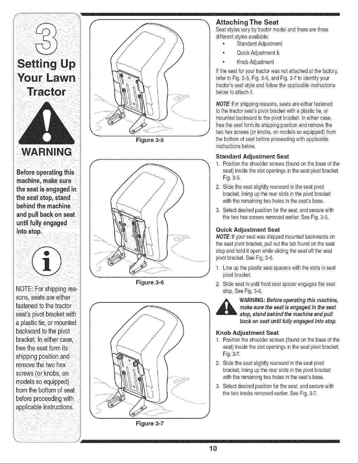
F--, _, Attaching The Seat
f f_ _ Seatstyles varybytractormodelandtherearethree
. .
--r 'J <] dfferentsty es ave abe
r--....._"j"_ • StandardAdjustment
• QuickAdjustment&
R
_l_tt II N tll ||1t_ • KnobAdjustment
If theseatfor yourtractorwas not attachedat the factory,
l
You r Lawn referto Fig. 3-5, Fig.3-6, andFig. 3-7to identifyyour
#tor
ING
Before operating this
machinemakesure
theseatengaged
the seat stop, stand
behind the machine
andpu,baoko,seat
until fully engaged
intostop.
i iill i iI i
NOTE:For Shipping tea!
sons seats are e_ther
fastened to the tractor
seat s pivotbracket w th
a plast,c t_e,or mounted
backward to the p vot
bracket.In either case,
free the seatform its
Shipping p°sition and
removethe two hex
screws (or knobs, on
models SOequqoped)
from the bottom of seat
. .
before proceed!rigw!th
apphcable _nstruct!ons.
Figure 3-6
tractor'sseatstyle andfollowthe applicableinstructions
belowto attachit.
NOTE:Forshippingreasons,seatsareeitherfastened
to the tractorseat'spivotbracketwith a plastictie,or
mountedbackwardto the pivotbracket.In eithercase,
freethe seat formitsshippingpositionand removethe
twohex screws(or knobs,on modelsso equipped)from
the bottomof seatbeforeproceedingwith applicable
instructionsbelow.
Standard Adjustment Seat
1. Positionthe shoulderscrews(foundon the baseof the
seat)insidethe slot openingsin the seat pivotbracket.
Fig.3-5.
2. Slide theseat slightlyrearwardin the seatpivot
bracket,liningupthe rear slots inthe pivotbracket
withthe remainingtwo holesin the seat'sbase.
3. Selectdesiredpositionforthe seat,and securewith
the twohexscrewsremovedearlier.SeeFig. 3-5.
Quick Adjustment Seat
NOTE:If yourseatwasshippedmountedbackwardson
the seatpivotbracket,pull outthe tab foundonthe seat
stopandhold it openwhileslidingthe seat offthe seat
pivotbracket.SeeFig. 3-6.
1. Line upthe plasticseatspacerswith the slotsin seat
pivotbracket.
2. Slide seatin until frontseat spacerengagesthe seat
stop.See Fig.3-6.
,_ WARNING:Before operating this machine,
makesure the seat is engagedin the seat
stop, stand behind the machine and pull
back on seat until fully engaged into stop.
Knob Adjustment Seat
1. Positionthe shoulderscrews(foundon the baseof the
seat)insidethe slot openingsin the seat pivotbracket.
Fig.3-7.
2. Slide theseat slightlyrearwardin the seatpivot
bracket,liningupthe rear slots inthe pivotbracket
withthe remainingtwo holesin the seat'sbase.
3. Selectdesiredpositionforthe seat,and securewith
the twoknobsremovedearlier.SeeFig. 3-7.
10

Identlfvma the Mulch Plua F "_ 1----.
On tractormodelsso equipped,a mulchplugcan be ( '_ ............. "_ [f-m
, , , g , , / / , ,
foundwthnthecuttngdeeksdsehargeopenng | _ " ' , | , _r J 4
• / 'x
• . ,, . / ...... |
)
NOTE:Referto Mulching tnthe OperattngYourLawn ..... \ , w /
Tractor secttonof thtsmanualfor moredetatledtnforma.......
tion. Setting p
If you'dpreferto operatethe cuttingdeckwithoutmulch- "'"
ing, simplyremovethe mulch plugby unthreadingthe ' your Lawn
plasticwing nutwhichfastensit to the cuttingdeck•This Tractor
will allowthe clippingsto dischargeout of the discharge
Ii
openingduringoperation.SeeFig.3-8.
Tire Pressure
_lk ARNING:Maximum tire pressure under
any circumstancesis 30psi. Equal tire
pressure should be maintained at all times.
The tiresonyour unitmaybe over-inflatedfor shipping
purposes.Reducethe tirepressurebeforeoperating
the tractor.Recommendedoperatingtire pressureis
approximately10p.s.ifor the reartires& 14p.s.i,for the
fronttires.Checksidewallof tirefor maximump.s.i.
Figure 3-8
WARNING
Max" "
imurn tire pres,
sure under any
circumstancesiS 30
psL Equal tire pressure
should be maintained
at all times.
NOTE:For shipping rea-
sons! seats are either
fastened tOthe tractor
seat s p!vot bracket w!th
a plastic tie, ormounted
backward tothe
brackeL In either case,
free the seat form its
shipping position and
rernovethe two hex
screws (or knobs, on
models so equ,pped)
from the bottom of seat
before proceedingWith
applicable instruction&
Ii_ i i
...... ;/
11

NOTE:Any reference
in this manual to the
RIGHTor LEFT side of
the tractor is observed
from operator's position.
NOTE: For shipping rea-
sons, seats are either
fastened to the tractor
seat's pivot bracket with
a plastic tie, or mounted
backward to the pivot
bracket. Ineither case.
Freethe seatform its
shippingposition and
removethe two hex
screws (or knobs, on
nodels so equipped)
from the bottom of seat
beforeproceeding with
applicable instructions.
Know Your Lawn Tractor
\
\
/ _-_J
i , ..............................)
Figure 4=1
g wheel
1 If so equipped
A SpeedControlLever/ParkingBrake E ThrottleControlLever
B Clutch-BrakePedal F IgnitionSwitchModule
C ShiftLever G DeckLift Lever
D ChokeControl1" H PTO(Blade Engage)Lever
NOTE:Anyreferencein thismanualto the RIGHTor LEFTside of the tractoris observedfrom operator'sposition.
12
i i _ i ii
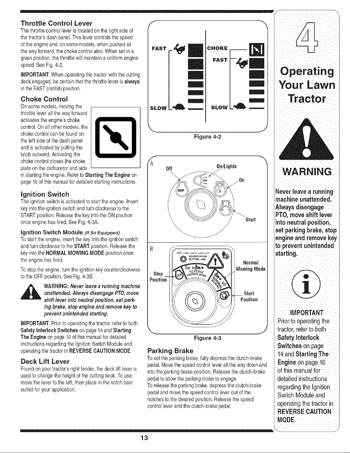
Throttle Control Lever ,f- _
Thethrottlecontrolleveris locatedon therightside of
thetractor'sdash panel.This levercontrolsthespeed
of the engineand,on somemodels,when pushedall
the wayforward,the chokecontrolalso.Whenset in a
givenposition,the throttlewill maintaina uniformengine
speed.SeeFig. 4-2.
IMPORTANT:Whenoperatingthetractorwiththe cutting
deckengaged,be certainthatthe throttleleveris always
inthe FAST(rabbit)position.
Choke Control
Onsomemodels,movingthe
throttleleverallthe wayforward
activatestheengine'schoke
control.Onall othermodels,the
chokecontrolcan befoundon
the leftside of thedash panel
andis activatedby pullingthe
knoboutward.Activatingthe
chokecontrolclosesthe choke
plateon the carburetorandaids
instartingthe engine.Referto Starting The Engine on
page16of thismanualfor detailedstartinginstructions.
ignition Switch
Theignitionswitchis activatedto startthe engine.Insert
keyintothe ignitionswitchand turnclockwisetothe
STARTposition.Releasethe key intothe ON position
onceengine hasfired. SeeFig.4-3A.
ignition Switch Module (Ifso Equipped)
Tostartthe engine,insertthe keyintothe ignitionswitch
andturnclockwiseto theSTARTposition.Releasethe
keyintothe NORMALMOWINGMODEpositiononce
the enginehasfired.
Tostop the engine,turnthe ignitionkey counterclockwise
to the OFFposition.See Fig.4-3B.
,_ WARNING:Never leavearunning machine
unattended. Always disengage PTO,move
shift lever into neutral position, set park-
ing brake, stop engine and removekey to
prevent unintended starting.
IMPORTANT:Prior to operatingthe tractor,referto both
Safety Interlock Switches on page 14andStarting
The Engine on page16of this manualfordetailed
instructionsregardingthe IgnitionSwitchModuleand
operatingthetractorin REVERSECAUTIONMODE.
Deck Lift Lever
Foundon yourtractor'srightfender,thedecklift leveris
usedto changethe heightof the cuttingdeck.To use,
movethe leverto the left, thenplacein the notchbest
suitedfor yourapplication.
FAST _,_
_LOW =_ ---,-- SLOW
mm
mmm.
Figure 4-2
f --,,
A
Off On/Lights
• _Start
Pnsition
©
Figure 4-3
WARNING
Never leave a running
machine unattended.
Awaysdsengage
PTO, move shift lever
into neutral position,
set parking brake stop
engineand remove key
to preventunintended
starting.
Pnor to operat!ngthe
tractor referto both
SafetyInterlock
Switches on page
Parking Brake
14 and Starting The
Toset the parkingbrake,fullydepressthe clutch-brake Engine on page 16
pedal.Movethe speedcontrolleverall the waydownand
intothe parkingbrakeposition.Releasethe clutch-brake of this manual for
pedalto allowthe parkingbraketo engage, detailed instructions
To releasetheparkingbrake,depresstheclutch-brake regard!ng.... the !gnltlon
pedalandmovethe speedcontrolleveroutof the .
Switch Moduleand
notchesto thedesiredposition.Releasethe speed . .
controlleverand the clutch-brakepedal, operating the tractor in
REVERSE CAUTION
13
Your Lawn
Tractor
WARNING
Do not operate the
tractor if the interlock
system is maffunctiom
ing. This system was
designed for your
iafety and protection:
NOTE: The parking
brake must beset if the
;
operator leavesthe Seat
with the engine run_
ning Or the enginewill
automaticallyshut off.
NOTE: The PTO(Blade
Engage) lever must be
in the disengaged (PTO
OFF) position when
sta[ting the engine:
iMPORTANT
Never force the shift
levei. Doing So
result in serious
damage to the tiactor s
transrnissionl
f
FORWARD
NUETRAL
REVERSE
J
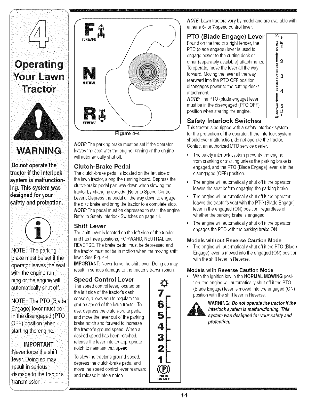
Figure 4-4
NOTE:The parkingbrakemustbe setif theoperator
leavestheseat withthe enginerunningor theengine
willautomaticallyshut off.
Clutch=Brake Pedal
Theclutch-brakepedal is locatedon the left side of
the lawntractor,along the runningboard.Depressthe
clutch-brakepedalpart waydownwhenslowingthe
tractorby changingspeeds (Referto SpeedControl
Lever).Depressthe pedalall theway downto engage
thedisc brakeand bringthe tractorto a completestop.
NOTE:The pedalmustbedepressedto start the engine.
Referto SafetyInterlockSwitcheson page14.
Shift Lever
Theshift leveris locatedonthe left sideof thefender
andhasthree positions,FORWARD,NEUTRALand
REVERSE.The brakepedalmustbe depressedand
thetractor mustnotbe in motionwhenthe movingshift
lever.SeeFig.4-4.
IMPORTANT:Neverforce theshift lever.Doingso may
resultinseriousdamageto the tractor'stransmission.
Speed Control Lever
Thespeedcontrollever,locatedon
the leftside of the tractor'sdash
console,allowsyouto regulatethe
groundspeedof the lawntractor.To
use,depressthe clutch-brakepedal
andmovethe leveroutof the parking
brakenotchand forwardto increase
thetractor'sgroundspeed.Whena
desiredspeedhas been reached,
releasethe leverintoan appropriate
notchto maintainthatspeed.
Toslow thetractor'sgroundspeed,
depresstheclutch-brakepedaland
movethe speedcontrolleverrearward
andreleaseit intoa notch.
0
NOTE:Lawntractorsvary by modelandare availablewith
eithera 6- or 7-speedcontrollever.
PTO (Blade Engage) Lever _,
f
Foundon thetractor'sright fender,the _ _-
PTO(bladeengage)leveris usedto --,
engagepowerto the cuttingdeckor t
other(separatelyavailable)attachments. ; 2
Tooperate,movethe leverall the way
forward.Movingthe leverall the way
_3
M
rearwardintothe PTOOFFposition
disengagespowerto the cuttingdeck/
attachment, i 4
NOTE:The PTO(bladeengage)lever
mustbe inthe disengaged(PTOOFF) _,5
positionwhenstartingthe engine. _ 4_
&*
Safety interlock Switches
Thistractoris equippedwitha safetyinterlocksystem
for the protectionof the operator.If the interlocksystem
shouldevermalfunction,do not operatethe tractor.
ContactanauthorizedMTDservicedealer.
• Thesafety interlocksystempreventstheengine
fromcrankingor startingunlessthe parkingbrakeis
engaged,and the PTO(BladeEngage)leveris inthe
disengaged(OFF)position.
• Theenginewill automaticallyshut off if theoperator
leavestheseat beforeengagingthe parkingbrake.
• Theenginewill automaticallyshut off if theoperator
leavesthetractor'sseatwiththe PTO(BladeEngage)
leverin the engaged(ON) position,regardlessof
whetherthe parkingbrakeis engaged.
• Theenginewill automaticallyshut off if theoperator
engagesthe PTOwiththe parkingbrakeON.
Models without Reverse Caution Mode
• Theenginewill automaticallyshut off if the PTO(Blade
Engage)leveris movedintothe engaged(ON) position
withthe shift leverin Reverse.
Models with Reverse Caution Mode
• Withthe ignitionkeyin the NORMALMOWINGposi-
tion,the enginewillautomaticallyshutoff if the PTO
(BladeEngage)leveris movedintothe engaged(ON)
positionwiththe shift leverinReverse.
,_ WARNING:Do not operate the tractor if the
interlock system is malfunctioning. This
system wasdesigned for your safety and
protection.
14
Reverse Caution Mode
(Models equipped with ignition switch
module)
_ ARNING:Use extreme caution while
operating the tractor in the REVERSE
CAUTIONMODE.Always look down and
behind before and while backing. Do
not operate the tractor when children
or others arearound. Stop the tractor
immediately if someone enters the area.
TheREVERSECAUTIONMODEpositionof the key
switchmoduleallowsthetractorto be operatedin
reversewiththe blades(PTO)engaged.
iMPORTANT:Mowingin reverseis notrecommended.
Touse the REVERSECAUTIONMODE:
iMPORTANT:TheoperatorMUSTbe seatedinthe
tractorseat.
1. Start the engineas instructedon page 16under
Starting The Engine.
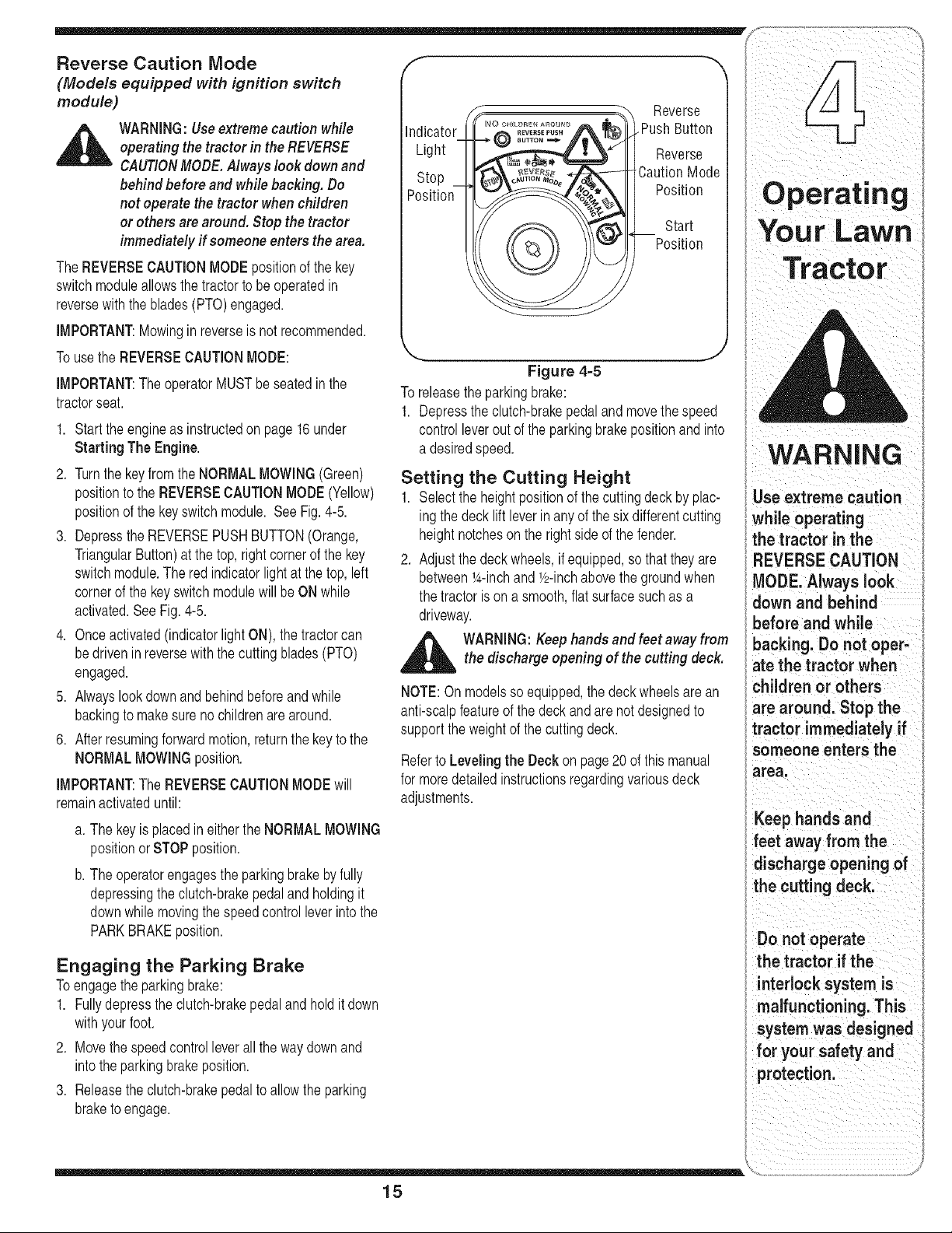
2. Turnthe keyfromthe NORMALMOWING(Green)
positionto the REVERSECAUTIONMODE(Yellow)
positionof the keyswitchmodule. SeeFig.4-5.
3. Depressthe REVERSEPUSHBUTTON(Orange,
TriangularButton)at the top,rightcornerof the key
switchmodule.The red indicatorlightat thetop, left
cornerof the keyswitch modulewill beON while
activated.See Fig.4-5.
4. Onceactivated(indicatorlightON), thetractorcan
bedrivenin reversewith the cuttingblades(PTO)
engaged.
5. Alwayslookdownand behindbeforeandwhile
backingto makesure nochildrenare around.
6. After resumingforwardmotion,returnthe keyto the
NORMALMOWINGposition.
iMPORTANT:The REVERSECAUTIONMODEwill
remainactivateduntil:
a. The keyis placedin eitherthe NORMALMOWING
positionorSTOPposition.
b. The operatorengagesthe parkingbrakebyfully
depressingtheclutch-brakepedaland holdingit
downwhilemovingthe speedcontrol leverintothe
PARKBRAKEposition.
Engaging the Parking Brake
Toengagethe parkingbrake:
1. Fullydepressthe clutch-brakepedalandhold it down
withyourfoot.
2. Movethe speedcontrolleverallthe waydownand
intothe parkingbrakeposition.
3. Releasethe clutch-brakepedalto allowthe parking
braketo engage.
f
Reverse
Indicator Push Button
Light Reverse
Stop CautionMode
Position Position
©
Start
Position
Figure 4-5
To releasetheparkingbrake:
1. Depressthe clutch-brakepedaland movethe speed
controlleverout of the parkingbrakepositionand into
a desiredspeed.
Setting the Cutting Height
1. Selectthe heightpositionof the cuttingdeck by plac-
ing thedeck liftleverin any of the sixdifferentcutting
heightnotcheson the rightside ofthe fender.
2. Adjustthe deckwheels,if equipped,so thattheyare
betweenl_-inchand Y2-inchabovethe groundwhen
the tractoris on a smooth,flat surfacesuchas a
driveway.
_lib ARNING: Keephands and feet away from
the discharge opening of the cutting deck.
NOTE:On modelssoequipped,the deck wheelsarean
anti-scalpfeatureof the deckand are not designedto
supporttheweightof the cuttingdeck.
Referto Leveling the Deck on page20 of thismanual
for moredetailedinstructionsregardingvariousdeck
adjustments.
WARNING
Use extreme caution
while operating
i the tractor in the
i REVERSE CAUTION
• MODE. Always ook
i down and behind
before and while
backing. Do not oper-
ate the tractor when
children or others
are around. Stop the
tractor immediately if
someone enters the
area.
Keep hands and
feet away from the
discharge opening of
the cutting deck.
Do not operate
the tractor if the
interlocksystem is
malfunctioning. This
system was designed
for your safety and
protection.
15

Operating
Your Lawn
WARNING
ifyou strike a foreign
object,stop the engine,
disconnectthe spark
plug wire(s) and
groundagainst the
engine.Thoroughly
inspectthe machine for
any damage. Repairthe
damage before restart-
ingandoperating.
Avoid sudden starts,
ex-cessive speed and
sudden stops.
Do not leavethe seat
of the tractor without
first placingthe PTO
(Blade Engage) leverin
the disengaged(OFF)
position, depressing
the brakepedal and
engagingthe parking
brake, if leavingthe
tractor unattended, also
turn the ignitionkey off
and remove the key.
Always look down
and behind before
and while backingup
to avoida back-over
accident.
Starting the Engine
_ ARNING:Do not operate the tractorif
the interlock system is malfunctioning.
This system was designed for your safety
andprotection.
NOTE:Referto the TRACTORSET-UPon page8 of
thismanualfor Gasolineand Oil fill-upinstructions.
1. insertthe tractorkeyinto the ignitionswitch.
2. Placethe PTO(BladeEngage)leverin the disen-
gaged(OFF)position.
3. Engagethetractor'sparkingbrake.
4. Activatethe chokecontrol.
5. Turnthe ignitionkeyclockwiseto the STARTposi-
tion.Afterthe enginestarts, releasethe key.it will
returnto theON (or NormalMowing)position.
IMPORTANT:Do NOT holdthe keyin the START
positionfor longerthanten secondsat a time. Doingso
maycausedamageto yourengine'selectricstarter.
6. After theenginestarts, deactivatethechoke control
andplacethe throttlecontrolin theFASTposition.
NOTE:Do NOTleavethechokecontrolon whileoperat-
ingthe tractor.Doingso will result ina "rich" fuelmixture
andcausethe engineto run poorly.
Stopping the Engine
,_ WARNING:If you strike a foreign object,
stop the engine, disconnect the spark
plug wire(s) and ground against the
engine. Thoroughly inspect the machine
for any damage.Repair the damage
before restarting and operating
1. if the bladesare engaged,placethe PTO(Blade
Engage)leverin the disengaged(OFF)position.
2. Turnthe ignitionkeycounterclockwiseto the STOP
position.
3. Removethe keyfromthe ignitionswitchto prevent
unintendedstarting.
Driving The Tractor
,_ WARNING:Avoid sudden starts, ex-ces-
sive speed and sudden stops.
WARNING:Do not leave the seat of the
tractor without first placing the PTO
(Blade Engage)lever in the disengaged
(OFF)position, depressing the brake
pedal and engaging the parking brake. If
leaving the tractor unattended, also turn
the ignition key off and remove the key.
Always look down and behind before and
while backing up to avoid a back-over
accident.
A
AVOID SERIOUS iNJURY OR DEATH
GO UP AND DOWNSLOPES,NOT ACROSS.
AVOIDSUDDENTURNS.
DO NOT OPERATETHE UNITWHERE IT COULDSLIP ORTIP.
IFMACHINESTOPSGOINGUPHILL,STOP BLADE(S)AND
BACK DOWNHILLSLOWLY.
DO NOT MOWWHEN CHILDRENOR OTHERS AREAROUND.
NEVER CARRYCHILDREN,EVENWITH BLADES OFE
LOOK DOWNAND BEHINDBEFOREAND WHILE BACKING.
KEEP SAFETY DEVICES(GUARDS,SHIELDS,AND BWlTCHE_
IN PLACEAND WORKING.
REMOVEOBJECTSTHATCOULDBE THROWNBYTHE
BLADE(S).
KNOW LOCATIONAND FUNCTIONOF ALL CONTROLS.
BE SUREBLADE(S) AND ENGINEARESTOPPEDBEFORE
PLACINGHANDSORFEET NEAR BLADE(S).
BEFORE LEAVINGOPERATOR'SPOSITION,DISENGAGE
BLADE(S), PLACETHE SHIFT LEVERIN NEUTRAL,ENGAGE
BRAKE LOCK, SHUT ENGINEOFF AND REMOVEKEY.
READ OPERATOR'S MANUAL
1. Depressthe brakepedalto releasethe parkingbrake
andlet the pedalup.
2. Movethe throttleleverintothe FAST(rabbit)position.
3. Placethe shift leverin eitherthe FORWARDor
REVERSEposition.
IMPORTANT:DoNOT usethe shift leverto changethe
directionof travelwhenthe tractoris in motion.Always
use the brakepedalto bring thetractorto a completestop
beforeshifting.
4. Releasethe parkingbrakeby depressingthe clutch-
brakepedaland positioningthespeedcontrol leverin
desiredposition.
IMPORTANT:First-timeoperatorsshouldusespeedposi-
tions 1 or2. Becomecompletelyfamiliarwiththe tractor's
operationand controlsbeforeoperatingthe tractorin
higherspeedpositions.
5. Releaseclutch-brakepedalslowlyto put unitinto
motion.
6. The lawntractoris broughtto a stop by depressingthe
clutch-brakepedal.
NOTE:Whenoperatingthe unitinitially,therewill be little
differencebetweenthe highesttwo speedsuntilafter the
beltshaveseatedthemselvesintothe pulleysduringthe
break-inperiod.
16
WARNING:Before leavingthe operator's
position for any reason,disengage the
blades,place the shift leverin neutral,
engagethe parking brake, shut engine off
and remove the key.
IMPORTANT:Whenstoppingthe tractorfor anyreason
whileon a grass surface,always:
1. Placetheshift leverin neutral,
2. Engagethe parkingbrake,
3. Shutengineoff andremovethe key.
Doingso will minimizethe possibilityof havingyour lawn
"browned" byhot exhaustfrom yourtractor'srunning
engine.
If unit stalls with speedcontrol inhighspeed,or if unit
will notoperatewith speedcontrol leverin a low speed
position,proceedas follows:
1. Placeshift leverinNEUTRAL.
2. Restartengine.
3. Placespeedcontrol leverin highestspeedposition.
4. Releaseclutch-brakepedalfully.
5. Depressclutch-brakepedal.
6. Placespeedcontrol leverin desiredposition.
7. Placeshift leverineitherFORWARDor REVERSE,
andfollownormaloperatingprocedures.
Driving On Slopes
Referto the SLOPEGAUGEon page3 to help determine
slopeswhereyou mayoperatethe tractorsafely.
,_ WARNING:Do not mow on inclines with
aslope in excess of 15degrees (arise of
approximately 2-1/2 feet every 10 feet). The
tractor could overturn and cause serious
injury.
,, Mow upanddownslopes,NEVERacross.
,, Exerciseextremecautionwhenchangingdirectionon
slopes.
,, Watchfor holes, ruts,bumps,rocks,orother hidden
objects.Uneventerraincouldoverturnthe machine.
Tallgrasscan hide obstacles.
,, Avoidturns whendrivingona slope.Ifa turn mustbe
made,turndownthe slope.Turningupa slope greatly
increasesthechanceof a roll over.
Engaging the Blades
Engagingthe PTO(BladeEngage)transferspowerto the
cuttingdeckor other(separatelyavailable)attachments.
To engagethe blades,proceedas follows:
1. Movethe throttlecontrollevertothe FAST(rabbit)
position.
2. Graspthe PTO(BladeEngage)leverandpivot it all
the wayforwardintothe engaged(ON) position.
3. Keepthe throttleleverinthe FAST(rabbit)position
for the mostefficient useof the cuttingdeckor other
(separatelyavailable)attachments.
IMPORTANT:Models with ReverseCaution Mode:
The enginewill automaticallyshutoff if the PTOis
engagedwiththe shift leverinpositionfor reversetravel
withthe ignitionkey inthe NORMALMOWINGposition.
Operating
Your Lawn
l
Modelswithout ReverseCaution Mode:
The PTO(Blade Engage)levermustbe in the disen-
gaged(OFF)positionwhenstartingthe engine,when
travelingin reverse,and if the operatorleavesthe seat.
l
Referto SafetyInterlockSwitcheson page14. WARNING
Using the Deck Lift Lever
To raisethe cuttingdeck,movethe decklift leverto
the left,then placeit in the notchbestsuitedfor your
application.Referto BettingThe CuttingHeightearlierin
thissection.
Do not mow On
inclineswith a slope
in excess of 15
degrees (a rise of
approximately 2-1/2
feet every 10 feet).
I The tractor could
overturn and cause
e i i jury
S r ous n
l
Avoidstoppingwhendrivingup a slope.If it is
necessaryto stopwhiledrivingup aslope,startup
smoothlyandcarefullyto reducethe possibilityof
flippingthe tractoroverbackward.
17
operating
) avoid blade
contact or a thrown
object injury, keep
bystanders,helpers,
chUdrenand pets at
least 75 feet from the
machine while it is in
operation. Stop ma-
chine if anyone enters
the area.
Plan your mowing
patternto avoid
discharge of materi-
als toward roads,
sidewalks, bystanders
and the like. Also,
avoid discharging
matedal against a wall
or obstruction which
may cause discharged
material to ricochet
back toward the
operator.
Mowing
,_ WARNING: Tohelp avoid blade contact or
a thrown object injury, keep bystanders,
helpers, children andpets at least 75feet
from the machine while it is in operation.
Stopmachine if anyone enters the area.
Thefollowinginformationwill be helpfulwhenusingthe
cuttingdeck withyourtractor:
,_ WARNING: Planyour mowing pattern
to avoid discharge of materials toward
roads, sidewalks, bystanders and the like.
Also, avoid discharging material against
a wall or obstruction which may cause
discharged material to ricochet back
toward the operator.
• Do not mowat highgroundspeed,especiallyif a
mulchkitor grasscollectoris installed.
• Forbest resultsit is recommendedthat the firsttwo
lapsbe cutwith the dischargethrowntowardsthe
center.Afterthefirst two laps,reversethedirection
to throwthe dischargeto the outsidefor the balance
of cutting.Thiswill givea better appearanceto the
lawn.
,, Do notcut the grasstoo short.Shortgrassinvites
weedgrowthand yellowsquicklyin dry weather.
,, Mowingshouldalwaysbe donewith theengine atfull
throttle.
,, Underheavierconditionsit may benecessaryto go
backoverthe cut areaa secondtime to get a clean
cut.
,, Do NOTattemptto mow heavybrushand weedsand
extremelytall grass.Yourtractoris designedto mow
lawns,NOTclearbrush.
,, Keepthe bladessharpandreplacethe bladeswhen
worn.Referto Cutting Blades onpage 25 of this
manualfor properbladesharpeninginstructions.
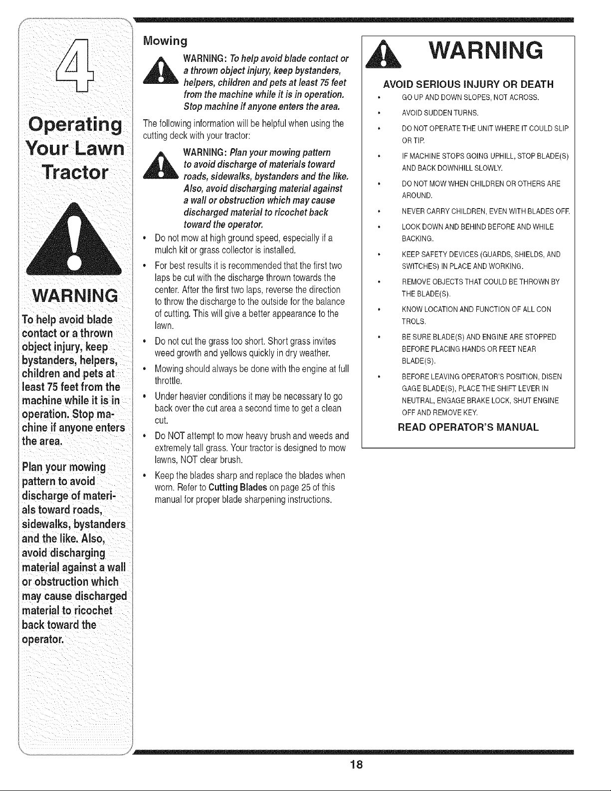
AVOID SERIOUS iNJURY OR DEATH
, GO UPAND DOWN SLOPES,NOT ACROSS.
* AVOIDSUDDENTURNS.
* DO NOT OPERATETHE UNITWHERE IT COULDSLIP
OR TIR
* IF MACHINESTOPS GOINGUPHILL,STOP BLADE(S)
AND BACK DOWNHILLSLOWLY.
* DO NOT MOWWHEN CHILDRENOROTHERS ARE
AROUND.
* NEVER CARRYCHILDREN,EVENWITH BLADESOFR
* LOOK DOWNAND BEHINDBEFOREAND WHILE
BACKING.
* KEEP SAFETYDEVICES(GUARDS,SHIELDS,AND
SWITCHES)IN PLACE ANDWORKING.
* REMOVEOBJECTSTHATCOULD BETHROWNBY
THE BLADE(S).
" KNOW LOCATIONAND FUNCTIONOF ALL CON
TROLS.
BE SUREBLADE(S) AND ENGINEARE STOPPED
BEFOREPLACING HANDSORFEET NEAR
BLADE(S).
* BEFORELEAVINGOPERATOR'SPOSITION,DISEN
GAGEBLADE(S), PLACETHE SHIFT LEVERIN
NEUTRAL, ENGAGEBRAKE LOCK, SHUT ENGINE
OFF AND REMOVEKEY.
READ OPERATOR'S MANUAL
18
Mulching
Selectmodelscomeequippedwith a mulchkit which
incorporatesspecialblades,alreadystandardon the
tractor,ina processof recirculatinggrass clippings
repeatedlybeneaththecutting deck.The ultra-fine
clippingsarethenforcedbackinto thelawnwherethey
actas a naturalfertilizer.
Observethe followingpointsfor the bestresultswhen
mulching:
,, Neverattemptto mulchif the lawnis damp.Wetgrass
tendsto stickto the undersideof the cuttingdeck
preventingpropermulchingof the clippings.
,, Do NOTattemptto mulch morethan 1/3the total
heightof thegrassor approximately1-1/2inches.
Doingso will causethe clippingsto clump upbeneath
the deckandnotbe mulchedeffectively.
,, Maintaina slowgroundspeedto allowthe grass
clippingsmoretimeto effectivelybe mulched.
,, Alwayspositionthe throttlecontrol leverin the FAST
(rabbit)positionand allowit to remaintherewhile
mowing.Failingto keepthe engineat full throttle
placesstrainonthe tractor'sengineand does not
allowthe bladesto properlymulchgrass.
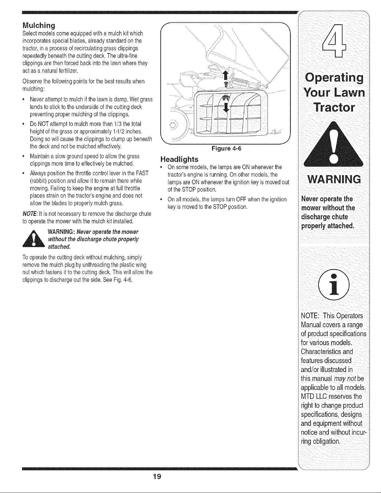
NOTE:It is not necessaryto removethedischargechute
to operatethe mowerwith the mulchkit installed.
,_ WARNING:Never operate the mower
without the discharge chute properly
attached.
Tooperatethe cuttingdeckwithoutmulching,simply
removethe mulchplug by unthreadingthe plasticwing
nut whichfastensit to thecuttingdeck.Thiswill allowthe
clippingsto dischargeout the side.SeeFig. 4-6.
Figure 4-6
Headlights
,, On somemodels,the lampsare ONwheneverthe
tractor'sengineis running.On othermodels,the
lampsareONwheneverthe ignitionkeyis movedout
of the STOPposition.
,, On allmodels,the lamps turnOFF whenthe ignition
keyis movedto the STOPposition.
l i i i
i!i_ _ _ i _ _i_i_iii
Your LaWn
TraCtor
i ii
WARNING
Never operate the
mower w thout the
discharge chute
proPer!Y attached,
I
l
I i_ i '
NOTE: This Operators
Manual Coversa range
of product speclficat ons
forvarious models.
i /
Characteristics and
features discussed
and/or illustratedin
th_smanua! maynot be
/ /
cable toall mo
ros0r os, h°;
right to change product
specifications, designs
and equipment without
notice and without incur-
ring obiigationl
19
1. With thetractorparkedona firm,levelsurface,place
Adj
ust|nq
Yo rL
U awn
Tract
or
Never attempt to
i make any adjust-
i merits while the
i engine is running,
i except where speci-
f ed n the operator s
i manual.
Figure 5-1
Figure 5-2
J
WARNING:Never attempt to make any
adjustments while the engine is running,
except wherespecified in the operator's
manual
the deckliftleverin the top notch(highestposition)
androtatethe blade nearestthe dischargechute so
thatit is parallelwiththe tractor.
2. Measurethe distancefromthe frontof thebladetip to
the groundandthe rearof the bladetip to the ground.
Thefirst measurementtaken shouldbe between
1/4" and3/8" lessthanthe secondmeasurement.
Determinethe approximatedistancenecessaryfor
properadjustmentandproceed,if necessary,to the
nextstep.
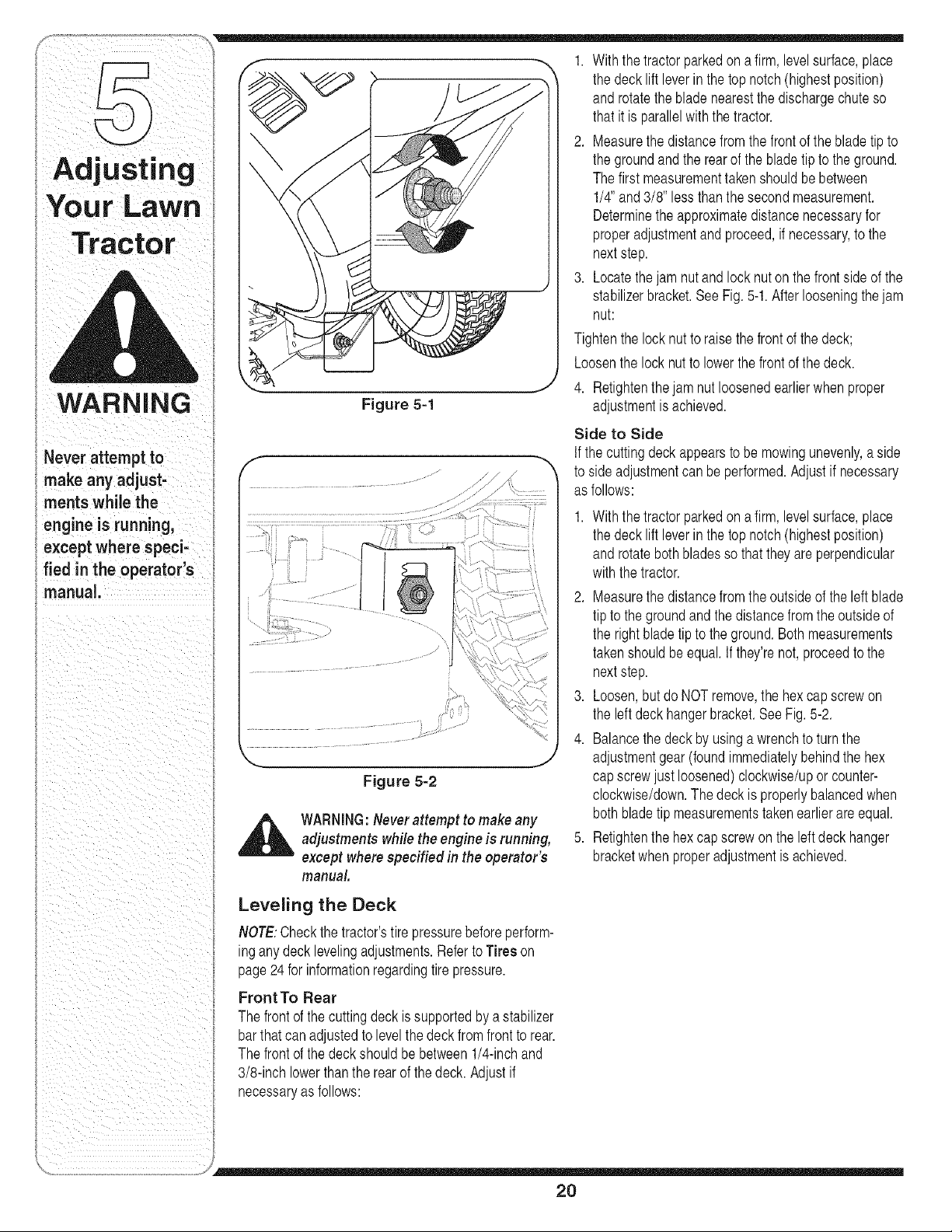
3. Locatethejam nutandlock nut on the frontsideof the
stabilizerbracket.SeeFig. 5-1.Afterlooseningthe jam
nut:
Tightenthe locknutto raisethe frontof the deck;
Loosenthe lock nut to lowerthe frontof the deck.
4. Retightenthe jam nut loosenedearlierwhenproper
adjustmentis achieved.
Side to Side
If thecutting deckappearsto bemowingunevenly,a side
to sideadjustmentcan be performed.Adjustif necessary
as follows:
1. With thetractorparkedona firm,levelsurface,place
the deckliftleverin the top notch(highestposition)
androtatebothbladesso that they are perpendicular
withthe tractor.
2. Measurethe distancefromthe outsideof the leftblade
tip to the groundandthe distancefrom theoutsideof
the rightblade tipto the ground.Bothmeasurements
takenshouldbe equal.If they'renot,proceedto the
nextstep.
3. Loosen,butdo NOTremove,the hexcap screwon
the leftdeckhangerbracket.See Fig.5-2.
4. Balancethe deckby usinga wrenchto turnthe
adjustmentgear(foundimmediatelybehindthe hex
capscrewjust loosened)clockwise/uporcounter-
clockwise/down.Thedeck is properlybalancedwhen
both bladetip measurementstakenearlierare equal.
5. Retightenthe hex capscrewon the left deckhanger
bracketwhenproperadjustmentis achieved.
Leveling the Deck
NOTE:Checkthe tractor'stirepressurebeforeperform-
ingany decklevelingadjustments.Referto Tires on
page24 for informationregardingtire pressure.
Front To Rear
The frontof the cuttingdeckis supportedbya stabilizer
barthatcan adjustedto levelthe deckfrom frontto rear.
The frontof the deckshouldbebetween1/4-inchand
3/8-inchlowerthanthe rear of thedeck. Adjustif
necessaryas follows:
2O
Parking Brake Adjustment
,_ WARNING:Never attempt to adjust the
brakes while the engine is running. Always
disengage PTO,move shift leverinto
neutral position, stop engine and remove
key to prevent unintended starting.
If the tractordoesnot cometo a completestop whenthe
brakepedal is completelydepressed,or if the tractor's
rearwheelscan rollwith the parkingbrakeapplied,the
brakeis in needof adjustment.See anauthorizedMTD
ServiceDealerto haveyourbrakesproperlyadjusted.
Seat Adjustment
NOTE:For shippingreasons,seatsare eitherfastened
to the tractorseat'spivotbracketwith a plastictie, or
mountedbackwardto the pivot bracket.In eithercase,
free theseat formits shippingpositionandremovethe
two hexscrews(or knobs,on modelsso equipped)from
the bottomof seat beforeproceedingwith applicable
instructions.
,j_ WARNING:Before operating this machine,
make sure the seat is engaged in the seat
stop, stand behind the machine and pull
back on seat until fully engaged into stop.
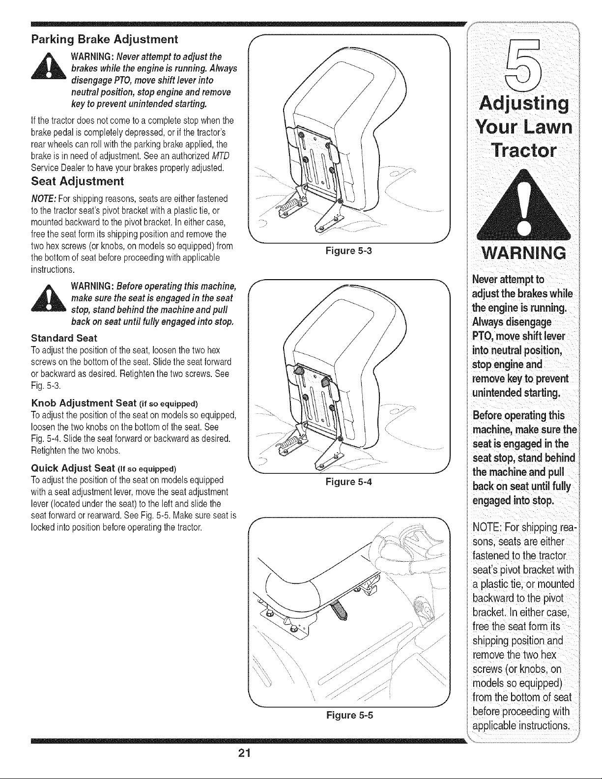
Standard Seat
Toadjust the positionof the seat,loosenthe two hex
screwson the bottomof the seat.Slidethe seatforward
or backwardas desired.Retightenthe two screws.See
Fig.5-3.
Knob Adjustment Seat (if so equipped)
Toadjust the positionof the seaton modelsso equipped,
loosenthe two knobsonthe bottomof the seat. See
Fig.5-4. Slidethe seatforwardor backwardas desired.
Retightenthe two knobs.
Quick Adjust Seat (if so equipped)
Toadjust the positionof the seaton modelsequipped
witha seatadjustmentlever,movetheseatadjustment
lever(locatedunder theseat) to the leftand slidethe
seatforwardor rearward.SeeFig.5-5. Makesureseatis
lockedintopositionbeforeoperatingthe tractor.
f
\
Figure 5-3
Figure 5-4
Adjust" g
|
Your Lawn
Tractor
WARNING
Never attempt to
adjust the brakes while
the eng'ne "s runn'ng
' Always disengage
PTO move shift lever
into neutral position,
stop engine and
remove key to prevent
unintended starting.
Before operating this
machine, make sure the
seat is engaged in the
seat stop, stand behind
the machineand pull
backon seat until fully
engaged into stop.
NOTE: For shipping rea-
sons. seats are either
fastened to the tractor
seat's pivot bracket with
a plastictie. or mounted
backward to the pivot
oracket. In either case.
free the seat form its
shipping position and
removethe two hex
screws (or knobs, on
_nodelsso equipped)
from the bottom of seat
before proceedingwith
applicable instructions,
........ /
21

Maintaining
Your LaWn
WARNING
Before performing
any maintenance or
repairs, disengage
PTO, move shift lever
into neutral position,
set parking brake, stop
engine and remove key
to prevent unintended
starting.
Before lubricating,
repairing, or inspect-
ing, always disengage
PTO, move shift lever
into neutral position,
set parking brake, stop
engine and remove key
to prevent unintended
starting.
KohlerSingle
\
ssi°glo .............
Figure 6-1
,_ WARNING:Beforeperforming any
maintenance or repairs,disengage PTO,
moveshift lever into neutral position, set
parking brake,stop engine and remove
key to prevent unintended starting.
Engine
Referto the Engine Operator/Owner Manualfor
enginemaintenance instructions.
Checkengineoil level beforeeachuseas instructed
in the EngineOperator/OwnerManualpackedwith your
unit.Fellow the instructionscarefully.
Changing Engine Oil
Fordrainingoil fromthe engine'scrankcaseof select
modeltractors,a plasticoil drainsleeveis packedwith
thisOperator'sManual.Todrainthe oil, proceedas
follows:
1. Unscrewthe oilfill capand removethe dipstickfrom
the oilfill tube.
2. Snapthe smallendof oil drain sleeveontothe oil
sump.See Fig.6-1.
3. Removedrainpluganddrain oil intoa suitable
containerwitha capacityof no lessthan 64 oz.
4. Servicethe oil filter (if so equipped)as instructedin the
separateEngineOperator/OwnerManualpackedwith
yourunit.
Performthe abovestepsin theoppositeorderafter oil has
finisheddraining.
5. Refillthe enginewith newmotoroilas instructedinthe
EngineOperator/OwnerManualpackedwithyour unit.
IMPORTANT:Referto the EngineOperator/Owner
Manualpackedwithyourunit for informationregardingthe
quantityand properweightof motoroil.
Air Cleaner
Servicethe pre-cleaner,if so equipped,and cartridge/air
cleanerelementas instructedin the EngineOperator/
OwnerManualpackedwith your unit.
Spark Plug(s)
Thespark plug(s)shouldbecleanedandthe gap reset
oncea season.Sparkplugreplacementis recommended
at the startof each mowingseason.Referto the Engine
Operator/OwnerManualfor correctplug type andgap
specifications.
Lubrication
_ ARNING:Before lubricating, repairing,or
inspecting, always disengage PTO,move
shift lever into neutral position, set parking
brake,stop engine and remove key to
prevent unintended starting.
Engine
Lubricatethe enginewithmotoroil as instructedinthe
EngineOwnerManualpackedwith your unit.
Pivot Points & Linkage
Lubricateall the pivotpointson the drivesystem,parking
brakeand lift linkageat least oncea seasonwithlightoil.
Rear Wheels
The rearwheelsshouldbe removedfromthe axles once
a season.Lubricatethe axles andthe rimswell withan
all-purposegreasebeforere-installingthem.
Front Axles
Eachend of the tractor'sfrontpivotbar may beequipped
witha greasefitting.Lubricatewitha greasegun after
every25 hoursof tractoroperation.
22

Cleaning the Engine And Deck
Anyfuel or oil spilledonthe machineshouldbewiped
offpromptly.DoNOTallowdebristo accumulatearound
the coolingfinsof the engine or on anyotherpart of the
machine.
IMPORTANT:The useof a pressurewasherto clean
yourtractoris NOTrecommended.It maycausedamage
to electricalcomponents,spindles,pulleys,bearingsor
the engine.
Deck Wash System TM
A hexplugcan be foundon yourtractor'sdeck surface.
SeeFig.6-2.
Thisplugcan be replacedwitha waterport to beused as
partof a separately-availabledeck washsystem.
Usethe DeckWash SystemTM to rinsegrassclippings
fromthedeck'sundersideandpreventthe buildupof
corrosivechemicals.
f
HexPlug
\
.....
/
Figure 6=2
J
NOTE:Referto page28 for informationregardingthis
andotherseparately-availableattachments& acces-
soriesfor yourtractor.
Cutting Deck Removal
NOTE:Modelsequippedwitha 38-inchdeck have
onedeckidler pulley.Modelsequippedwitha 42-and
46-inchdeck havetwodeck idlerpulleys.
Toremovethe cuttingdeck, proceedas follows:
1. Placethe PTO(BladeEngage)leverin the disen-
gaged(OFF)positionandengagethe parkingbrake.
2. Lowerthe deckby movingthedeck lift leverinto the
bottomnotchon the rightfender.
3. Removethe belt from aroundthe tractor'sengine
pulleyand idlerpulley(s).Refer toChangingthe Deck
Belton page26 for detailedinstructions.
4. Lookingat the cuttingdeck fromthe leftsideof the
tractor,locatethe hairpin clip that securesthe deck
supportrodon the rearleftsideof thedeck.
SeeFig.6-3.
5. Removethe hairpin clipthatsecuresthedeck
supportrod, andcarefullyremovethe deck support
fromthedeck lift arm.
6. Repeatthe abovestepson the tractor'srightside.
7. Movethe decklift leverintothe top notchonthe right
fenderto raisethedeck lift arms upand out of the
way.
8. Carefullyremovethe PTOcablefromthe rearof
the cuttingdeck by removingthe hair pin clipwhich
securesit. Removethe springfromthe deck idler
bracket.SeeFig.6-4.
9. Gentlyslidethe cuttingdecktowardthefrontof the
tractorallowingthe hookson the deckto release
themselvesfromthedeckstabilizerrod.
10.Gentlyslidethe cuttingdeck(from the rightside)out
fromunderneaththetractor.
Figure 6-3
l E E R i
llVlalntalnlng
Your Lawn
Tractor
Figure 6=4
23
NOTE: Models
equippedwith a 38-inch
deck have one deck
idler pulley.Models
equipped with a 42- and
46-inch deck have two
deck idler pulleys,
WARNING
Never exceedthe
maximum inflation
pressure shown on
the sidewall of the
tire.
Batteries give off an
explosive gas while
charging. Charge
battery in a well
ventilated area and
keep away from an
openflame or pUot
light as on a water
heater, space heater,
furnace, clothes
dryer or other gas
appliances.
Always use a fuse
with the same
amperage capacity
for replacement.
Tires Jump Starting
,_ WARNING:Neverexceedthe maximum
inflation pressure shown on the sidewall
of tire.
The recommendedoperatingtire pressureis:
Approximately10psi for the reartires
Approximately14psi for the fronttires
IMPORTANT:Referto the tire sidewallforexacttire
manufacturer'srecommendedor maximumpsi. Do not
overinflate.Uneventire pressurecouldcausethe cutting
deckto mowunevenly.
Battery
The batteryis sealedand is maintenance-free.Acid
levelscannotbe checked.
Alwayskeepthe batterycablesandterminalsclean
andfreeof corrosivebuild-up.
Aftercleaningthe batteryand terminals,apply a light
coatof petroleumjelly or greasetoboth terminals.
Alwayskeepthe rubberbootpositionedoverthe
positiveterminalto preventshorting.
IMPORTANT:If removingthe batteryforany reason,
disconnectthe NEGATIVE(Black)wire from it's terminal
first,followedbythe POSITIVE(Red)wire.When
re-installingthe battery,alwaysconnectthe POSITIVE
(Red)wire its terminalfirst,followedbythe NEGATIVE
(Black)wire.Becertainthat thewires areconnectedto
thecorrectterminals;reversingthemcould changethe
polarityandresultin damageto your engine'salternat-
ingsystem.
Charging
IMPORTANT:Whenchargingyour tractor'sbattery,use
onlya chargerdesignedfor 12Vlead-acidbatteries.
Readyourbatterycharger'sOwner'sManualpriorto
chargingyourtractor'sbattery.Alwaysfollow its instruc-
tionsandheed itswarnings.
If yourtractorhasnot been put intousefor an extended
periodof time,chargethe batteryas follows:
,, Setyour batterychargerto delivera maximumof 10
amperes.Ifyourbatterychargeris automatic,charge
the batteryuntilthe chargerindicatesthat chargingis
complete.
NOTE:If the chargeris notautomatic,chargefor no
fewerthaneight hours.
,_ WARNING:Batteries give off an explosive
gas while charging. Charge battery in a
well ventilated areaand keep away from
an open flame or pilot lightas on a water
heater,space heater,furnace, clothes
dryer or other gas appliances.
,_lk WARNING:Whenremovingor installing the
battery, follow theseinstructions toprevent
the screwdriver from shorting against the
frame.
iMPORTANT:Neverjumpyourtractor'sdead batterywith
the batteryof a runningvehicle.
1. Connectendof onejumpercableto the positive
terminalof thegood battery,thenthe otherendto the
positiveterminalof the deadbattery.
2. Connectthe otherjumpercableto the negative
terminalof thegood battery,thento the frame of the
unit withthe dead battery.
3. Start the tractor as instructedon page 15.
_ ARNING:Failure to use this procedure
could cause sparking, and the gas in either
battery could explode.
Cleaning
Cleanthe batteryby removingit fromthe tractorand
washingwitha bakingsodaandwatersolution.If neces-
sary,scrapethe batteryterminalswith a wire brushto
removedeposits.Coatterminalsand exposedwiringwith
greaseor petroleumjelly topreventcorrosion.
Battery Failures
Somecommoncausesfor batteryfailureare:
• incorrectinitialactivation • undercharging
• overcharging • corrodedconnections
• freezing
Thesefailures are NOTcovered by your tractor's
warranty.
Fuse
One20AMPfuseis installedin yourtractor'swiringhar-
nessto protectthe tractor'selectricalsystemfrom damage
causedby excessiveamperage.
If the electricalsystemdoes notfunction,or your tractor's
enginewill not crank,first checkto be certainthatthe fuse
has notblown.It can befoundunderthe hoodmounted
behindthe dashpanelon the rightside.
,_ WARNING:Always use a fuse with the
sameamperage capacity for replacement.
24

Cutting Blades
,_ WARNING:Be sure to shut the engine
off, removeignitionkey, disconnectthe
spark plug wire(s) and ground against
the engine to prevent unintended starting
before removing the cutting blade(s) for
sharpening or replacement. Protect your
hands by using heavy gloves or a rag to
grasp the cutting blade.
WARNING:Periodically inspect the blade
spindles for cracks or damage, especially
if you strike a foreign object. Replace
immediately if damaged.
Thebladesmaybe removedas follows.
1. Removethe deckfrombeneaththe tractor,(referto
CuttingDeckRemovalon page23) thengentlyflip
the deckoverto exposeits underside.
2. Placea blockof wood betweenthe centerdeckhous-
ingbaffleand the cuttingbladeto act asa stabilizer.
SeeFig.6-5.
3. Removethe hexflangenutthat securesthe bladeto
the spindleassembly.See Fig.6-5.
4. Toproperlysharpenthe cutting blades,removeequal
amountsof metalfrombothends of the bladesalong
the cuttingedges, parallelto the trailingedge,at a
25° to 30° angle.
IMPORTANT:If the cuttingedgeof the bladehasalready
beensharpenedto within 15/8" fromthe edge,or if any
metalseparationis present,replacethe bladeswith new
ones.SeeFig.6-6.
,, It is importantthateachcuttingblade edgebeground
equallyto maintainproperbladebalance.
,, A poorlybalancedbladewill causeexcessive
vibrationand maycausedamageto thetractorand
resultinpersonalinjury.The bladecan be testedby
balancingit ona roundshaftscrewdriver.Grind metal
fromthe heavysideuntil it balancesevenly.
,, Whenreplacingthe blade,be sureto installthe blade
withthe sideof the blademarked"Bottom" (or with
a part numberstampedin it) facingthe groundwhen
the moweris inthe operatingposition.
iMPORTANT:Useatorquewrenchto tightenthe blade
spindlehexflangenutto between70 foot-poundsand 90
foot-pounds.
F
f
Figure 6-5
Figure 6-6
Idlerpulleys
Idlerpulleynuts
Figure 6-7
ng
Your Lawn
I Be sure to shut the
lengine off, remove
iignition key, discon-
inect the spark plug
wire(s) and ground
against the engine to
_revent unintended
starting before remov-
ing the cutting blade(s)
for sharpening or
replacement. Protect
your hands by using
heavy gloves or a rag
to grasp the cutting
blade.
Periodicallyinspect
the blade spindles for
cracks or damage,
especially if you strike
a foreign object.
Replace immediately if
damaged.
25

WARNING
Be sure to shut the
engine off, remove
ignition key, discon-
nect the spark plug
wire(s) and ground
against the engine to
prevent unintended
starting before remov-
ing the belt.
Avoid the possibility of
a pinching injury. Do
not place your fingers
on the idler spring or
betweenthe belt and a
pulleywhile removing
he belt.
Changing the Deck Belt
,_ WARNING:Besure to shut the engine
off, removeignition key, disconnect the
spark plug wire(s) and ground against
the engine to prevent unintended starting
before removing the belt.
Allbelt on yourtractorare subjectto wearandshouldbe
replacedif any signsof wearare present.
IMPORTANT:The V-beltfoundon yourtractorare
speciallydesignedto engageand disengagesafely.A
substitute(non-OEM)V-beltcan bedangerousby not
disengagingcompletely.Fora properworkingmachine,
usefactory approvedbelts.
Tochangeorreplacethe deck belt onyourtractor,
proceedas follows:
1. Lowerthe deck by movingthedeck liftleverintothe
bottomnotchon the right fender.
2. Removethe beltguardsby removingtheself-tapping
screwsthatfastenthem to the deck.
3. Removethe beltkeeperrodfromaroundthe engine
pulley.
4. On the 42-inchdeck only, loosenbut do notremove,
the idlerpulleynuts.Thiswill enablethebelt to be
easilyremovedfrom the idler pulleys.See Fig. 6-7on
the previouspage.
,_ WARNING:Avoid thepossibility of a pinch-
ing injury. Do not place your fingers on the
idler spring or between the belt and a pulley
while removing the belt.
5. Removethe deck belt fromaroundall pulleys,including
the deckidlerpulley.
6. Routethe newbelt as shownin andFig.6-8, 6-9 or
6-10.
7. Remountthe beltguardsremovedearlier.
Changing the Lower Deck Belt (46" Decks)
NOTE:Severalcomponentsmustbe removedin orderto
changethe tractor'slowerdeck belt. Seean authorized
MTDServiceDealerto haveyourlowerdrivebelt replaced
orphoneCustomerSupportas instructedon page2 for
informationon orderinga Service Manual.
Changing the Transmission Drive Belt
NOTE:Severalcomponentsmustbe removedand special
tools(i.e.air/impactwrench)in orderto changethe
tractor'sdrivebelt. Seean authorizedMTDServiceDealer
to haveyourdrivebelt replacedorphoneCustomerSup-
port as instructedon page2 for informationon orderinga
ServiceManual.
Engine Pulley 38-Inch Deck
Idler Bracket
\
Deck Idler Pulley
Figure 6-8
26

Engine Pulley 42-Inch Deck
\
Idler Bracket
Deck Idler Pulleys
Figure 6-9
f
46-InchDeck
©
©
Belt Cover Idler Pulleys
Figure 6-10
27
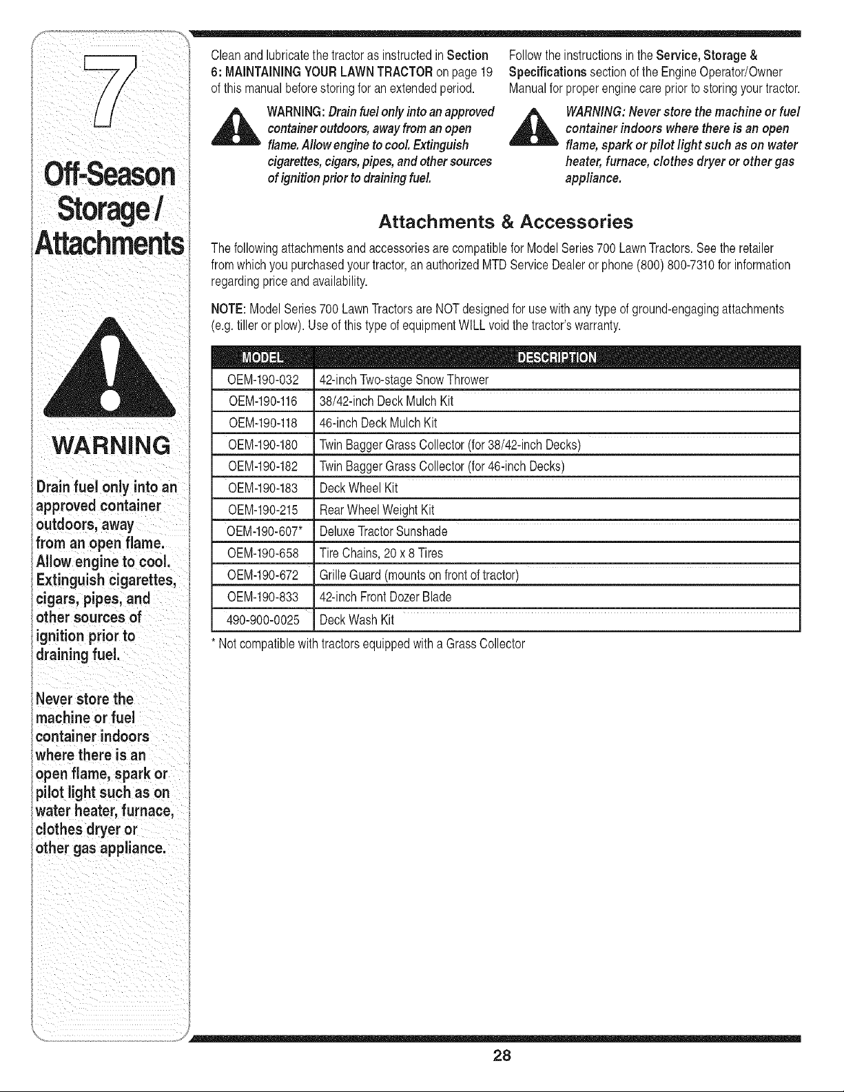
F 1 Cleanandlubricatethe tractoras instructedin Section Followthe instructionsin the Service, Storage &
P 6: MAINTAININGYOURLAWNTRACTORon page19 Specifications sectionof the EngineOperator/Owner
of thismanualbeforestoringfor anextendedperiod. Manualfor properenginecare priorto storingyourtractor.
l
l
i
i
Off-Season
Storage!
Attachments
_ ARNING:Drainfuel only into anapproved
containeroutdoors,awayfroman open
flame.Allow engine to cool Extinguish
cigarettes,cigars,pipes, and other sources
of ignition prior to draining fuel
WARNING:Never store the machine or fuel
container indoors where there is an open
flame, spark or pilot light such as on water
heater;furnace, clothes dryer or other gas
appliance.
Attachments & Accessories
The followingattachmentsandaccessoriesare compatiblefor ModelSeries700 LawnTractors.Seethe retailer
fromwhichyou purchasedyour tractor,an authorizedMTDServiceDealeror phone(800) 800-7310for information
regardingpriceand availability.
NOTE:ModelSeries700 LawnTractorsare NOTdesignedfor usewith any type of ground-engagingattachments
(e.g.tiller or plow).Use of thistype of equipmentWILLvoidthe tractor'swarranty.
i WARNING
i Drain o an
fuel only int
i approved container
outdoors, away
ifrom an open flame.
iAllow engine to cool.
i Extinguish cigarettes,
iicl'gars, p'ples, and
i other sources of
_ignition prior to
i dra n ng fue.
0EM-190-032 42-inchTwo-stageSnowThrower
0EM-190-116 38/42-inchDeckMulchKit
0EM-190-118 46-inch DeckMulchKit
0EM-190-180 TwinBaggerGrassCollector(for38/42-inchDecks)
0EM-190-182 TwinBaggerGrassCollector(for46-inch Decks)
0EM-190-183 DeckWheel Kit
0EM-190-215 RearWheelWeightKit
0EM-190-607' DeluxeTractorSunshade
0EM-190-658 Tire Chains,20 x 8 Tires
0EM-190-672 GrilleGuard(mountson frontoftractor)
0EM-190-833 42-inchFrontDozerBlade
490-900-0025 DeckWash Kit
Notcompatiblewith tractorsequippedwitha GrassCollector
i Never store the
machine or fuel
container indoors
where there is an
lopen flame, spark or
i pilot light such as on
iwater heater, furnace,
iclothes dryer or
iother gas appliance.
28

ROTATING BLADES CAUSE
SERIOUS INJURY OR DEATH
• DONOTMOWWHENCHILDRENOR
OTHERSAREAROUND
• NEVERCARRYCHILDRENEVENWITH
BLADE(S)OFF.
• LOOKDOWNANDBEHINDBEFORE
ANDWHILEBACKING.
l
WARNING
I
This symbol points
out importantsafety
instructionswhich, if
notfollowed,could
endangerthe personal
safetyand/or property
of yourselfand others.
Read andfollow all
instructionsin this
manual beforeat-
temptingto operate
this machine.Failure
to cornply withthese
instructionsmayresult
in personalinjury.When
yousee this symbol.
HEED ITS WARNING!
Your Responsibility
Restrictthe use
of this power machine
to persons who read.
understand
and follow the warn,ngs
and instructions
in this manual
and on the machine.
29

'Trot
Shootin
For repairs
beyond the minor
adjustments listed
here, contact an
authorized service
dealer.
Problem Cause Remedy
Eng ne fa s to start 1. PTOengaged• 1. PlacePTO knob(or ever) n
disengaged(OFF)position•
2. Sparkplugwire(s) disconnected. 2. Connectwire(s) to sparkplug(s).
3 Fueltank em t or stalefuel 3 F tank wth c ean,freshgaso ne
• py . .
4 Chokenot activated 4. Pullout the CHOKEcontrol(if so
equipped)orplacethe throttle
controlinCHOKEposition.
5. Faultysparkplug. 5. Clean,adjustgap,or replace•
6. Blockedfuel hne. 6. Cleanfuel line or replacefuelfilter,
7 Engineflooded if so equip ed
• • p •
7. Crank enginewiththrottle in FAST
position•
8. Parkingbrakenot engaged• 8. Engageparkingbrake•
9. Throttlecontrollevernotin correct 9. Placethrottleleverto FAST
startingposition• position•
Engine runs erratic
1. Unitrunningwith CHOKEapplied.
2. Sparkplug wire(s)loose.
3. Blockedfuel lineor stale fuel.
4. Ventin gas cap plugged.
5. Wateror dirt infuel system.
6. Dirty air cleaner.
_ J
1. PushCHOKEcontrol(ifso
equipped)in, or movethethrottle
controloutof the CHOKEposition.
2. Connectand tightenspark
plugwire(s).
3. Cleanfuel line;fill tankwithclean,
fresh(lessthan30 daysold)
gasoline.Replacefuel filter,if so
equipped.
4. Clearvent or replaceif damaged.
5. Drainfuel tank. Refillwith
freshfuel.
6. Replaceaircleanercartridge/ele-
mentorclean pre-cleaner,if so
equipped.
_ J
30

Problem Cause Remedy
Engine overheats !. Engineoil level!ow.
2. Clean grassclippingsanddebris
' from aroundthe engine!scooling
finsandblowerhousing.
Enginehesitates at 1. Sparkplug(s)gap tooclose. 1. Removespark plug(s)and reset
high RPM thegap.
IdleS poorly spark plug(s)fou!e& !au!ty 0rgap !. RePlacespa!k p!ug(s),set plug(s)
' to° wide' I gap.
2. Dirty air cleaner. 21 Replaceair cleanercartridge!ele-
mentor €leanpre_€leaner,if So
equipped.
Excessive 1. Cuttingbladelooseor unbalanced. 1. Tightenbladeandspindle.
Vibration Balanceblade.
2. Damagedor bentcutting blade. 2. Replaceblade.
Mowerwi!l not !' Engine speedtO°low. I !: P!acethrottle Contro!in FAST
mulch grass I 2 Wet grass I (rabbit)position
odelse quipped 2 , Do not mowwhengrass swet;
withamuich'kit' I wat unt aterto cut
_) 3. Excessivelyhighgrass.
3. Mowonceata highcuttingheight,
then mowagainat desiredheight
I or makea narrowercutt ng path
I
4. Dullblade. 4. Sharpenor replaceblade.
Uneven cut
1. Decknotbalancedproperly.
2. Dullblade.
3. Uneventire pressure.
1. Performside-to-sidedeckadjust-
ment.
2. Sharpenor replaceblade.
3. Checktire pressureinall four
tires.
31
Trouble
Shootin
beyond the minor
adjustments listed
here, contact an
authorized service
dealer.

Replacement
l = i
Parts
GRHUIHX
_FACTORY PARTS
WARNING
l
/
f a safety feature
as not functionin¢
properly, do not use
the tractor. Contact
your authorized MTD
service deaJeror call
(800) 800-7310
i ill ii iii
This Operators
Manua covers a range
of product specifications
for various models,
Characteristics and
features discussed
, ,
and/or illustrated in
l !
this manual maynotbe
applicable to all models,
l
MTD LLO reserves the
nght to changeproduct
spec_flcat!ons,designs
and equipment without
noticeand without
_ncurring obligation,
NOTE:Phone(800) 800-7310to orderreplacementpartsor acompletePartsManual(have
your full modelnumberand serialnumberready).PartsManualdownloadsare also available
freeof chargeat www.mtdproducts.com.
DriveBelt (Transmission)
DriveBelt (MowingDeck)38" Deck
DriveBelt (MowingDeck)42" Deck
UpperDriveBelt (MowingDeck)46" Deck
LowerDriveBelt(MowingDeck)46" Deck
DeckBlades(38" Deck- twoeach)
DeckBlade(42"Deck)
DeckBlade(46" Deck)CenterBlade(oneea.)
DeckBlade(46" Deck)OuterBlade (two ea.)
DeckSpindle(38"Deck)
DeckSpindle(42"Deck)
DeckSpindle(46"Deck)DoublePulley(one ea.)
DeckSpindle(46"Deck)(twoeach)
DeckWheels
Battery(13hp Tecumseh)
Battery(15.5hp Briggs& Stratton)
Tire (Front)15x 6 x 6 RoundShoulder
Tire (Front)15x 6 x 6 SquareShoulder
Tire (Rear)20 x 8 x 8 RoundShoulder
Tire (Rear)20 x 8 x 8 SquareShoulder
HubCap
FuelTankCap
ChokeControl/Cable(TwinCylinderEngines)
ThrottleControl/Cable(SingleCylinderEngines)
DischargeChuteAssembly
754-04001A
754-04062
754-04060B
754-04142
754-0349
742-0610A
742-0616A
742-0612A
742-0611A
618-04197
618-04456
618-04134B
618-0240A
734-0973
725-1704A
725-1737A
734-0864
734-1731
734-1596
734-1730
731-0484A
951-3111
746-1085A
746-04258
931-1032B
32

NOTES
Use this page to make notes and write down important information.
33

CALiFORNiA EMiSSiON CONTROL WARRANTY STATEMENT
YOUR WARRANTY RIGHTS AND OBLiGATiONS
The CaliforniaAir ResourcesBoardand MTDConsumerGroup Inc are pleasedto explainthe evaporativeemissioncontrolsystemwarrantyon your2007 lawn
mower.In California,new lawnmowermust be designed,built andequippedto meet theState'sstringentanti-smogstandards.MTDConsumerGroupInc must
warrantthe EECSon your lawnmowerfor the periodof time listedbelow providedthere has beenno abuse,neglector impropermaintenanceof your lawnmower.
YourEECSmayincludeparts such as the carburetor,fuel-injectionsystem,the ignitionsystem,catalyticconverter,fuel tanks,fuel lines,fuel caps,valves,
canisters,filters,vapor hoses,clamps,connectors,and otherassociatedemission-relatedcomponents.
Where a warrantableconditionexists, MTDConsumer Group Inc will repair your lawnmower at no costto you includingdiagnosis, parts and labor.
MANUFACTURER'S WARRANTY COVERAGE:
Thisevaporativeemissioncontrol systemis warrantedfor twoyears. If anyevaporativeemission-relatedpart onyour equipmentis defective,the partwill be
repairedor replacedby MTDConsumerGroup Inc.
OWNER'S WARRANTY RESPONSiBILITiES:
Asthe lawn mowerowner,you are responsiblefor performanceof the requiredmaintenancelistedin your owner'smanual. MTDConsumerGroupInc recom-
mendsthat you retain all receiptscoveringmaintenanceon your lawnmower,but MTDConsumerGroupInc cannotdenywarrantysolelyfor the lackof receipts.
Asthe lawn mowerowner,you shouldhoweverbeawarethat MTDConsumerGroup Inc maydenyyou warrantycoverageif yourlawn moweror a part has failed
dueto abuse,neglect, orimpropermaintenanceor unapprovedmodifications.
Youare responsiblefor presentingyourlawn mowerto MTDConsumerGroupInc's distributioncenter or servicecenter as soonas the problemexists.The
warrantyrepairsshouldbe completedin a reasonableamountof time, not to exceed30 days.If you havea questionregardingyour warrantycoverage,you should
contactthe MTDConsumerGroupIncService Departmentat 1-800-800-7310.
GENERAL EMISSIONS WARRANTY COVERAGE:
MTDConsumerGroupIncwarrantsto the ultimatepurchaserandeachsubsequentpurchaserthat the lawnmower is: Designed,built and equippedso as to
conformwithall applicableregulations;and freefrom defectsin materialsand workmanshipthatcausethe failure of a warrantedpart to be identicalin all material
respectsto that part as describedin MTDConsumerGroup Inc'sapplicationfor certification.
The warrantyperiodbeginson the datethe lawnmoweris deliveredto an ultimatepurchaseror first placedinto service.Thewarranty periodis twoyears.
Subjectto certain conditionsand exclusionsas statedbelow,the warrantyon emission-relatedparts is as follows:
1. Any warrantedpart that is not scheduledfor replacementas requiredmaintenanceinthe writteninstructionssupplied, is warrantedfor the warrantyperiod
statedabove. If the part fails duringthe periodof warrantycoverage,the partwill be repairedor replacedby MTDConsumerGroupInc accordingto subsection
(4) below.Any such part repairedor replacedunderwarrantywill be warrantedfor the remainderof the period.
2. Any warrantedpart that is scheduledonly for regular inspectioninthe writteninstructionssuppliedis warrantedfor the warranty periodstated above.Any such
part repairedorreplacedunderwarrantywill be warrantedfor the remainingwarrantyperiod.
3. Any warrantedpart that is scheduledfor replacementas requiredmaintenanceinthe written instructionssuppliedis warrantedfor the periodof time beforethe
first scheduledreplacementdatefor that part. If the part failsbeforethe first scheduledreplacement,the part will be repairedor replacedby MTDConsumer
GroupInc accordingto subsection(4) below.Anysuch part repairedor replacedunderwarrantywillbe warrantedfor the remainderof the periodpriorto the
first scheduledreplacementpointfor the part.
4. Repairor replacementof any warrantedpart underthewarrantyprovisionshereinmustbe performedat a warrantystationat no chargeto theowner.
8. Notwithstandingthe provisionsherein,warrantyservicesor repairswill be providedat all of our distributioncentersthat arefranchisedto servicethe subject
enginesor equipment.
6. The lawnmowerowner will not be chargedfor diagnosticlaborthat is directlyassociatedwithdiagnosisof a defective,emission-relatedwarrantedpart,
providedthat such diagnosticwork is performedat a warrantystation.
7. MTDConsumerGroupInc is liablefor damagesto other engineor equipmentcomponentsproximatelycaused bya failure underwarrantyof any warranted
part.
8. Throughoutthe lawnmowerwarrantyperiodstated above,MTDConsumerGroup Incwill maintaina supplyof warrantedparts sufficientto meetthe expected
demandfor such parts.
9. Any replacementpart maybe usedinthe performanceof any warrantymaintenanceor repairsand mustbe providedwithoutchargeto the owner.Suchuse will
not reducethe warrantyobligationsof MTDConsumerGroupInc.
10.Add-onor modifiedpartsthat are notexemptedbythe Air ResourcesBoardmaynot be used.The use of any non-exemptedadd-onor modifiedparts by the
ultimatepurchaserwill be groundsfor disallowinga warrantyclaims. MTDConsumerGroup Incwill notbe liableto warrantfailures of warrantedparts caused
bythe use of a non-exemptedadd-onor modifiedpart.
WARRANTED PARTS:
The repairor replacementof any warrantedpartotherwiseeligiblefor warrantycoveragemay be excludedfromsuch warrantycoverageif MTDConsumerGroup
Inc demonstratesthat thelawn mowerhas been abused,neglected,or improperlymaintained,andthat such abuse,neglect,or impropermaintenancewas the
directcauseof the need for repairor replacementof the part.That notwithstanding,any adjustmentof a componentthat has a factory installed,and properly
operating,adjustmentlimiting deviceis still eligiblefor warrantycoverage.The following emissionwarrantyparts list are covered:FuelLine,Fuel Line Clamps

MANUFACTURER'S LiMiTED WARRANTY FOR
Thelimitedwarrantyset forthbelowis givenby MTDLLCwithrespect
to new merchandisepurchasedand usedin the UnitedStates,its
possessionsand territories.
"MTD"warrantsthis productagainstdefectsin materialandworkman-
shipfor a periodof two (2) yearscommencingon thedate of original
purchaseandwill,at its option,repairor replace,free of charge,any
partfound tobe defectiveinmaterialsor workmanship.This limitedwar-
rantyshallonlyapply if this producthas beenoperatedand maintained
inaccordancewith theOperator'sManualfurnishedwiththe product,
andhas notbeensubjectto misuse,abuse,commercialuse,neglect,
accident,impropermaintenance,alteration,vandalism,theft, fire, water,
ordamagebecauseof otherperil or naturaldisaster.Damageresulting
fromthe installationor useof any part, accessoryor attachmentnot
approvedby MTDfor use with the product(s)coveredbythis manual
will voidyourwarrantyas to any resultingdamage.
Normalwearpartsare warrantedto befree fromdefects in materialand
workmanshipfor aperiodof thirty (30) daysfromthe date of purchase.
Normalwearparts include,butare notlimitedto itemssuch as: batter-
ies,belts,blades,bladeadapters,grass bags, riderdeckwheels,seats,
snowthrowerskidshoes,shaveplates,augerspiralrubberandtires.
HOW TO OBTAIN SERVICE: Warranty service is available, WITH
PROOFOF PURCHASE,through your local authorized service
dealer. To locate the dealer in your area, check your Yellow Pages,
or contact MTD LLC at RO. Box 361131,Cleveland, Ohio 44136-
0019, or call 1-800-800-7310 or 1-330-220-4683 or log on to our
Web site at www.mtdproducts.com.
Thislimitedwarrantydoesnot providecoveragein the followingcases:
a. Theengineor componentpartsthereof.These itemsmaycarry a
separatemanufacturer'swarranty.Referto applicablemanufacturer's
warrantyfor termsand conditions.
b. Logsplitterpumps,valves,andcylindershavea separateone year
warranty.
c. Routinemaintenanceitemssuch as lubricants,filters, blade
sharpening,tune-ups,brakeadjustments,clutchadjustments,deck
adjustments,andnormaldeteriorationof the exteriorfinishdueto
useor exposure.
d. Servicecompletedbysomeoneotherthanan authorizedservice
dealer.
e. MTDdoesnot extendanywarrantyfor productssold or exported
outsideof the UnitedStates,itspossessionsandterritories,except
thosesold throughMTD'sauthorizedchannelsof export distribution.
f. Replacementparts thatarenot genuineMTDparts.
g. Transportationchargesandservicecalls.
No impliedwarranty, includingany impliedwarranty of mer-
chantabilityof fitness for a particularpurpose,applies after the
applicable periodof expresswritten warranty above as to the
partsas identified.No other expresswarranty, whether written or
oral,exceptas mentioned above,givenby any personor entity,
includinga dealeror retailer,with respectto any product,shall
bind MTD.Duringthe periodof the warranty,the exclusiveremedy
is repair or replacementof the productas set forth above.
Theprovisionsas set forth in this warranty providethe soleand
exclusiveremedyarising from the sale. MTDshallnot be liable
for incidentalor consequentialloss or damageincluding,without
limitation,expensesincurredfor substituteor replacement lawn
careservicesor for rental expensesto temporarily replace a
warranted product.
Somestatesdo notallowthe exclusionor limitationof incidentalor
consequentialdamages,or limitationson how longan impliedwarranty
lasts,so the aboveexclusionsor limitationsmaynotapply to you.
In noeventshallrecoveryof any kindbegreaterthanthe amountof the
purchasepriceof the productsold. Alterationof safety features of
the product shall void this warranty. Youassumethe risk and liability
for loss,damage,or injuryto you and yourpropertyand/orto othersand
theirpropertyarisingout of the misuseor inabilityto usethe product.
This limitedwarrantyshallnot extendto anyoneotherthan the original
purchaserorto the personfor whomit was purchasedas a gift.
HOWSTATELAW RELATESTO THISWARRANTY: This limited
warrantygivesyou specificlegalrights,and youmay also haveother
rightswhichvaryfrom stateto state.
IMPORTANT:OwnermustpresentOriginalProofof Purchasetoobtain
warrantycoverage.
MTD LLC, P.O. BOX 361131 CLEVELAND, OHIO 44136-0019; Phone: 1-800-800-7310, 1-330-220-4683
GDOC-100015REV.A

