Loading ...
Loading ...
Loading ...
English 12
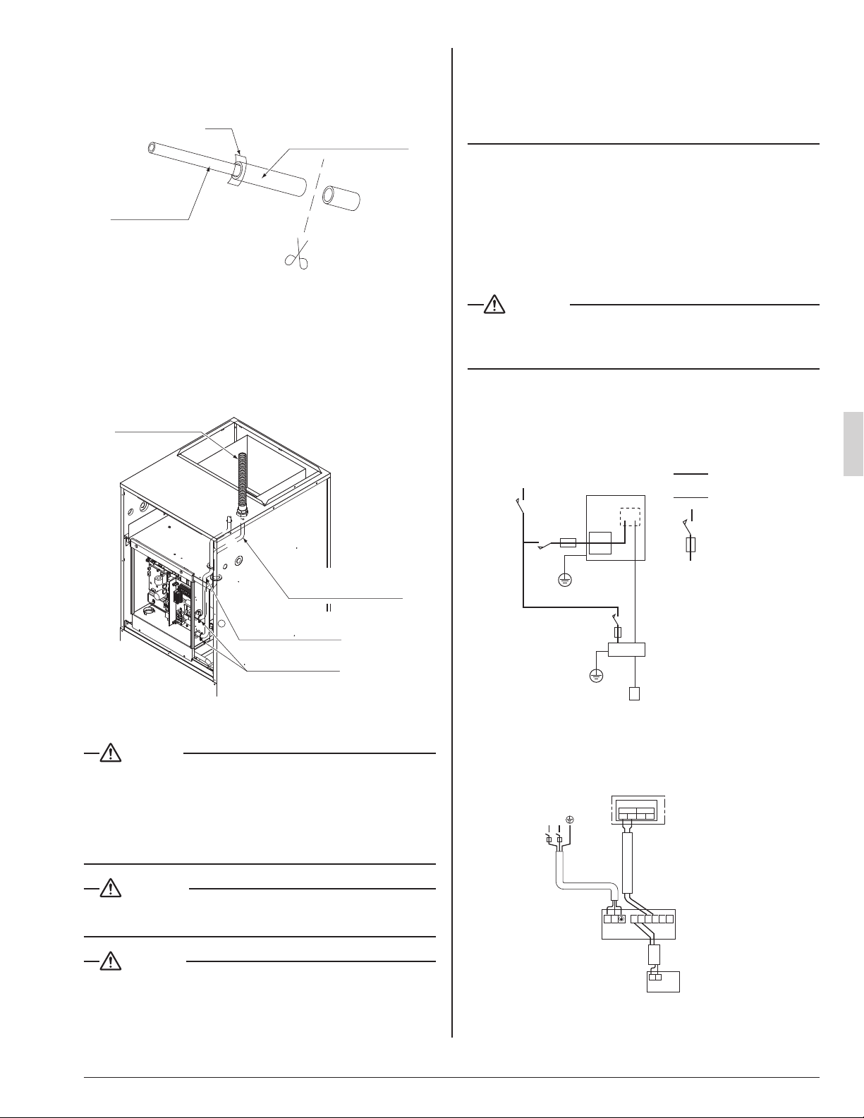
How to use insulation tube.
Use the insulation tube to cover the wiring.•
Joint the insulation tube with the tape and cut off the tube •
sticking out of the unit.
Insulation tube large (3)
Insulation tube
small (2)
Tape
Cut off the sticking
out of the unit.
Pass the power supply wiring and the ground wire (4)
through the conduit (conduit should be fi eld sup-
plied). The hole for running wires through should be
sealed completely to prevent air from entering.
* When installing an optional electric heater kit, run both
the power supply wiring and ground wire of the electric
heater kit through the conduit.
Pass through the
conduit
Clamp material (1)
(accessory)
Remote controller and
transmission wiring
Power supply wiring
and ground wire
Install the front panel (upper).(5)
DANGER
Use only specifi ed wire and connect wires to terminals •
tightly. Be careful that wires do not place external stress on
terminals. Keep wires in neat order so as to not to obstruct
other equipment. Make sure that the electric component box
cover closes tightly. Incomplete connections could result in
overheating, and in worse cases, electric shock or fi re.
WARNING
Never connect power supply wiring to the terminal block for
•
remote controller wiring as this could damage the entire system.
CAUTION
When doing the wiring, make sure the wiring is neat and
•
does not cause the electric front panel to stick up, then close
the panel fi rmly. When attaching the front panel, make sure
you do not pinch any wires.
Outside the air conditioners, separate the low voltage wiring •
(remote controller and transmission wiring) and high voltage
wiring (ground wire and power supply wiring) by at least 5 in.
so that they do not pass through the same place together.
Proximity may cause electrical interference, malfunctions,
and breakage.
[ PRECAUTIONS ]
Refer to the “REMOTE CONTROLLER INSTALLATION •
MANUAL” on how to install and lay the wiring for the remote
controller.
See also the “Wiring Diagram Label” located inside the unit’s •
blower deck.
Connect the remote controller and transmission wiring their •
respective terminal blocks.
CAUTION
Do not, under any circumstances, connect the power supply •
wiring to the remote controller or transmission wiring termi-
nal block. Doing so can destroy the entire system.
[ WIRING EXAMPLE ]
Fit the power supply wire of each unit with a switch and fuse •
as shown in the drawing.
COMPLETE SYSTEM EXAMPLE
Power supply
Main
switch
Outdoor unit
Power supply wire
Transmission wire
Switch
Overcurrent
Protective device
Indoor unit
Remote controller
When using 1 remote controller for 1 indoor unit. (Nor-1.
mal operation)
L1L2
IN/D OUT/D
F
1 F2 F1 F2
P
1
P
2
P
1
P
2
F
1
F
2
T
1
T
2
Power supply
208/230V
~
60Hz
Control box
Outdoor unit
Indoor unit
Remote controller
(option)
L
1
L
2
01_EN_3P250363-4E.indd 1201_EN_3P250363-4E.indd 12 6/9/2016 4:56:58 PM6/9/2016 4:56:58 PM
Loading ...
Loading ...
Loading ...