MT-2017
Protective Function Analog Multimeter
User’s Manual
1
st
Edition
,
2015
©2015 Copyright by Prokit’s Industries Co., Ltd.

1
INTRODUCTION
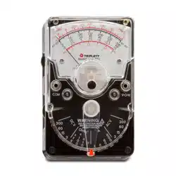
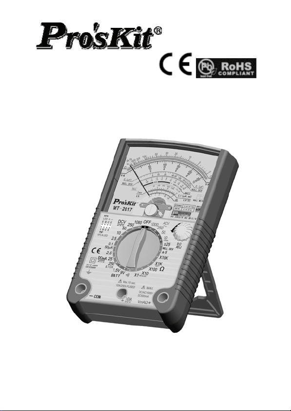
This Multi-meter is an accurate, safe handheld meter that comes
with robust protective holster alongside, built-in stand and hook-up
design. MT-2017 is powered by batteries, offers accurate, reliable
measurement of DC/AC Voltage, +/-DCV, DC Current, Resistance
and Diode, LED, Transistor, Decibels, Continuity test and
Capacitance with very high sensitivity quality movement.
This meter is designed with double-sided glass-epoxy PCB, full
overload & misused protection via two Fuses, Oxide Varactor &
Diodes, as well as mirrored Aluminum dial plate. Ideal for indoor
use in the laboratory, school, workshop, hobby and home
applications.
SPECIFICATION
Safety Category: IEC61010-1, CAT II 1000V, CAT III 500V and
Pollution Degree 2.
Common Environment: 23C5C, less than 75% RH.
Operating temperature: 0C to 40C, 32 F to 104 F
Storage temperature: -10 C to 50C, 14 F to 122F
Operating Humidity Scope: less than 90% RH.
Storage Humidity Scope: less than 80% RH.
Dimensione: 171(W) x 108(D) x 37(H) MM
Weight: 390g approx. (including batteries 3pcs)
Accessories: One pair of test leads;
Two Spare Fuses: 0.5A/250V & 10A/250V, Φ5x20mm
Test
Functions
Range Accuracy Remarks
DC V 0-0.1-2.5-10-50-
250 V-1000V
3% FSD.
4% FSD.
For 1000V
Input Impedance:
20KΩ /V Overload
Protection: Max.
1000V AC/DC
BUT 0.1V/2.5V/10V
250V Max.
Null DCV ±-5V, ±25V 5% FSD.
Input Impedance:
40KΩ /V Overload
1000V Max.
AC V 0-10-50-250V
-1000V
4% FSD.
5% FSD.
Input Impedance:
9KΩ /V Overload

2
For 1000V Protection: Max.
1000V AC/DC
But 10V/50V only
250V Max. Band
width: 40 ~10K Hz
DC mA 0-0.05-2.5-25-25
0 mA, 10A
3% FSD.
4% FSD.
For 10A
Drop Voltage: 250
mV Overload
protected by Fuses
0.5A/250V & 10A /
250V at 10A range,
and Oxide
Varactor.<250V
AC/ DC(5s). Max.
test time 15sec. for
10A.
Ω X 1: 0.2 ~ 2KΩ
Midscale at 20Ω
X 10: 2 ~ 20KΩ
Midscale at
200Ω
X 100: 20 ~
200KΩ
Midscale at
2000Ω
X1K: 200~ 2MΩ
Midscale at
0KΩ
X10K: 2K
~20MΩ
Midscale at
200KΩ
4% of
ARC of
Scale
Length
Overload protected
by the Oxide
Varactor & Fuse
<250V AC/DC (5s).
Capacitance
(uF)
C: 2,000uF Max.
.
Approx.
Value
Use the R x 1K
range
BATT Check 0 ~ 1.5V: GOOD
- ? – BAD
0 ~ 9V: GOOD
- ? – BAD
5% of
ARC of
Scale
Length
Load Current:
270mA for 1.5V
25mA for 9V
Overload protected
by Fuse & Oxide
Varactor .<250V
AC/DC(5s).
Transistor
Check
hFE: 0-1000 via
special hFE
socket
Approx.
Value
At Ω X 10 Range
LED, Diode via special hFE Approx. At Ω X 10 Range
3
Check socket Value
Decibel -22 dB ~ + 62
dB (0dB=1mW
at 600Ω )
Approx.
Value
At ACV ranges
Via Test Leads
Continuity
Check
Beeper
sounding under
200 Ohm
Overload protected
by Fuse & Oxide
Varactor .<250V
AC/DC(5s).
POWER
Source
Internal Battery:
R3P, AAA, 1.5V
2pcs, 6F22,
NEDA1604, 9V
1pc
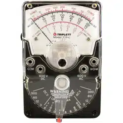
CALIBRATION
Ohms Zero Adjustor located at the right side of the panel.
Adjust the meter pointer to the Zero mark on the right side of
Ohm scale of the meter dial when the test leads are touched
together.
Mechanical Adjustor Screw: located right side below the center
of the meter dial to set pointer to Zero mark at the left side of
the scale.
(-) Jack: Plug-in connector at the lower left on the panel for
black, negative test lead.
(+) Jack: Plug-in connector at the lower right on the panel for
Red, positive test lead.
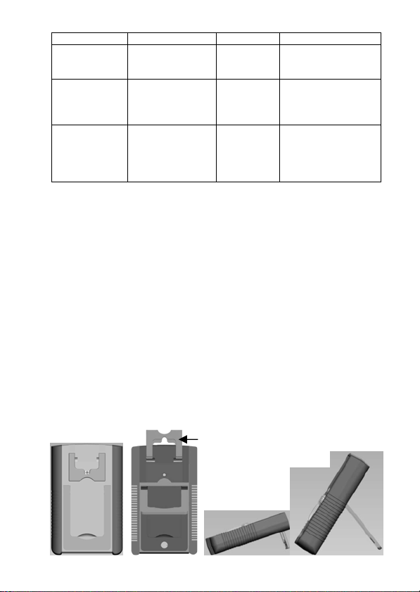
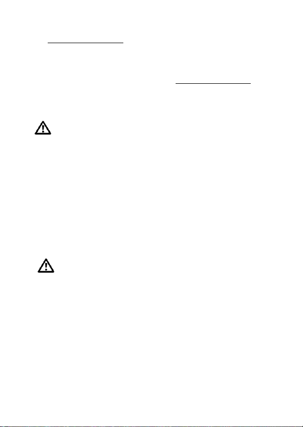
STAND & HOOK-UP
This meter can be used in any operating position. It has two rear
support devices, i.e. the upper small bracket and the lower big tilt
device. The upper one not only performs the light slanted position,
but also hook-up the tester which makes it easier to place the
tester and read the display when measuring.
And the lower big tilt device can provide the steeper slant degree
position easy for user’s reading too.
Hook-up
Upper Tilt
Device
Big Lower
Tilt Device

4
OPERATING INSTRUCTIONS
CAUTION!
When making voltage or current measurements, develop the
habit of turning off all power to the circuit under test. Connect the
test leads at the desired points in the circuit, and then turn on
the power while taking readings. Turn off the power before
disconnecting the test leads from the circuit.
INTERNAL BATTERY CHECK
To check the battery condition, insert the black test lead into the
(-) jack. Set the range switch to the R X1 range position and
short the ends of the two sides of the test leads. If the pointer
can not be brought to the zero mark, replace the 1.5V cells or 9V
cell. (See battery replacement.)
BEFORE OPERATING
1. Set the range switch to the proper position before making any
measurement.
2. Never apply more voltage or current than the rated value in
every position.
3. When the voltage or current to be measured it not known,
always start with the highest range.
4. If meter indication is in the lower half of the scale and falls
within the range of a lower scale, reset selector switch to the
lower range for greatest accuracy.
5. If the meter won’t work at all, check the fuse located on the
PCB. If it’s blown, replace it. (See fuse replacement.)
6. Avoid placing the meter where extreme shock or continuous
vibration is encountered and do not store in excessively hot or
damp places. Although very rugged, the meter is a sensitive
measuring device and should be handled carefully & properly.
7. Do not check resistance, transistor, diode, LED, or
capacitance when live voltage or current input across the
circuit.
8. When the meter is not in use, keep the selector switch to the

5
“OFF” range position, this provides direct short across meter
movement for minimum needle bounce when transporting
meter.
9. If you should accidentally apply excessive voltage or current
on a certain range, disconnect the leads from the circuit as
quickly as possible, check instrument operation on that range
by applying peoper input. If the meter does not operate
properly, check fuse. If it is blown replace it. (See fuse
replacement.)
OPERATION PROCEDURES
DC Voltage Measurement
WARNING: USE EXTREME CARE WHEN MAKING
MEASUREMENTS FOR HIGH VOLTAGE. DO NOT TOUCH
TERMINAL OR PROBE ENDS.
1. Set the selector switch to the appropriate DCV range to be
used.
2. Connect the BLACK test lead to the “-COM” jack and the RED
test lead to the “+” jack.
3. If you know the polarity of the circuit to be tested, connect the
black probe to the negative side.
4. If you don’t know the polarity, connect the probes to opposite
sides of the circuit and watch the pointer. If it goes to the left,
reverse the probes. The RED probe will be connected to the
positive.
5. Check the needle position and the get the reading on V.A scale.
Null DCV (Central Zero) Measurement
At these two ranges, it can automatically judge the polarity of
circuit as the pointer can move to the center line and become a
Null meter.
1. Set the selector switch to the DCV ±5V or 25V range.
2. Connect the BLACK test lead to the “-COM” jack and the RED
test lead to the Red “+” jack.
6
3. Set the Zero Ω adjustor to place the pointer exactly to the
Central Zero position
if need.
4. Connect the test leads across the circuit or load under
measurement.
5. Take the readings on the Red dial Null DCV scale.
NOTE: If the needle failed to be set at Central Zero position
, the
power of 9V battery may be weak and should be replaced by
new one for normal working.
AC Voltage Measurement
WARNING: USE EXTREME CARE WHEN MAKING
MEASUREMENTS FOR HIGH VOLTAGE. DO NOT TOUCH
TERMINAL OR PROBE ENDS!
1. Set the selector switch to the appropriate ACV range to be used
and connect the test leads across the circuit or load under
measurement. (Polarity of the test probes is unimportant on ACV
test.)
2. Connect the BLACK test lead to the “-COM” jack and the RED
test lead to the“+” jack.
3. Check the needle position and the get the reading on V.A scale.
DC Current Measurement
WARNING: DO NOT APPLY VOLTAGE TO MEASURING
TERMINAL WHILE RANGE SWITCH IS IN CURRENT POSITION.
DO NOT ATTEMPT TO MEASURE AC CURRENT.
1. Set the selector switch to the appropriate DC mA range to be
used and connect the test leads in series with the circuit or the
load under measurement. If the pointer deflects to the left,
reverse the probes.
2. Connect the BLACK test lead to the “-COM” jack and the RED
test lead to the Red “+” jack for Current at/less than 0.25A. For
large current max. 10A, move the red test lead to the Red “10A”
jack.

7
3. Check the needle position and the get the reading on V.A scale.
Note:
Excessive current input across mA range will blow the fuse
that must be replaced by a same fuse rating 0.5A/250V or
10A/250V. The max. testing time once must be not more than
15sec. and pause 5min. for next time at big current load.
The Maximum terminal voltage drop is 250mV except for the
10A range.
Note: If connected incorrectly with the voltage at these ranges,
quickly remove the test leads from the circuit as to avoid
damage to this tester.
(This tester can afford the voltage <250V DC/AC rms. for the
period of 5 seconds max.)
Resistance Measurement
WARNING: DO NOT APPLY VOLTAGE TO MEASURING
TERMINAL WHILE RANGE SWITCH IS IN OHM POSITION.
1. Set the selector switch to the appropriate Ω range to be used.
2. Connect the BLACK test lead to the “-COM” jack and the RED
test lead to the Red “+” jack.
3. Short the leads by touching the probes together. Pointer should
read zero at the right hand end of the upper most scale, if it
doesn’t, use the Ohm adjust knob on the right hand of the panel
to line up the pointer with zero. (If pointer can’t be brought to
zero, replace battery.)
4. Connect the test leads across the resistance to be measured.
5. Take reading on the top “Ω” scale and multiply it by the
multiplication factor indicated by the selector switch.
6. If there is little or no pointer movement from the left side of the
scale, reset the selector switch to higher range. The effective
reading scope on an Ohm meter scale is within the area of
between 25 degree of Arc left side to the Midscale and 25
degree right side to the Midscale.
Note: If connected incorrectly with the voltage, quickly remove

8
the test leads from the circuit as to avoid damage to this tester.
(This tester can afford the voltage <250V DC/AC rms. for the
period of 5 seconds max.)
Diode Measurement
1. Set the selector switch to the appropriate Ω range to be used.
NOTE: To test the diode while current below 0.060 mA at X 10K
range; current below 0.15 mA at X 1K range; current below 1.5
mA at X 100 range; current below 15 mA at X 10 range; current
below 150 mA at X 1 range.
2. For IF (forward current) test, put the BLACK test lead to the
“-COM” jack and the RED test lead to the Red “+” jack. And then
connect the Black probe to the Positive terminal of the Diode,
the Red probe to the Negative terminal of the Diode.
For IR (reverse current) test, reverse the connection.
3. Read the value IF or IR of the diode on the LI scale.
4. Read the linear (forward voltage) VF of the diode on the LV
scale.
Continuity Test
WARNING: DO NOT APPLY VOLTAGE TO MEASURING
TERMINAL WHILE RANGE SWITCH IS IN OHM POSITION.
Set the selector switch to the BUZZ range. Connect the test leads
to two points of circuit. If the resistance is lower than 200 Ohm
approx., the Beeper sounds.
Note: Battery voltage is sufficient for Buzzer operation as long as
the Zero Ohm pointer can be adjusted to the Zero scale place.
Note: If connected incorrectly with the voltage, quickly remove
the test leads from the circuit as to avoid damage to this
tester..
(This tester can afford the voltage <250V DC/AC rms. for the
period of 5 seconds max.)

9
Transistor hFE and LED Test
1. Set the selector switch to the R X 10 range.
FOR Measuring Transistor hFE
2. Take note the type of transistor “PNP” or “NPN” and then insert
the transistor terminals of the Emitter, Base and Collector
separately into the proper holes of the socket on the front panel.
3. Read the approximate hFE Value directly at the hFE scale.
Note: Current 10μA. VCE 2.8V.
4. When the Base terminal cut, the value of Leak is Iceo for
Transistor.
FOR Measuring LED: Insert the transistor terminals directly into
the “+” and “-” holes of the socket on the front panel.
And then check if the LED under testing is lighting.
Battery Check
1. This meter comes with two separate battery check ranges to test
either DC 1.5V or 9V batteries.
2. Set the selector switch to the appropriate BATT range to be
used.
3. Connect the BLACK test lead to the “-COM” jack and the RED
test lead to the Red “+” jack.
4. Connect the Red test lead to the positive end of battery and the
Black one to the negative end of the battery to be measured.
5. Take reading on the “BATT” scale and check it good or bad as
per which portion indicated.
(Note: the mark section of “?” shows that the battery may be
starting to decay.)
Note: If connected incorrectly with the voltage, quickly remove
the test leads from the circuit and can avoid the damage to
this tester.
(This tester can afford the voltage <250V DC/AC rms. for the
period of 5 seconds max.)

10
Decibels Measurement
1. Set the selector switch to AC 10V range.
2. Connect the BLACK test lead to the “-COM” jack and the RED
test lead to the Red “+” jack.
3. Connect the test leads to the measuring circuit specially in
series with a 0.047μF/400V Metalized Polyester Capacitor.
And then read the bottom Red dB scale.
4. For more dB scope, change the selector switch to the others
of ACV ranges and make the same actions. Add the
appropriate number of dB scale reading as noted on the chart
below.
NOTE: For absolute dB measurements, circuit impedance
must be 600 Ohm. 0 dB = 1mw dissipated in a 600 Ohm
impedance (equivalent to 0.755V across 600 Ohm)
ACV RANGE ADD dB Number
50 14
250 28
1000 40
Capacitance Measurement
WARNING: DO NOT APPLY VOLTAGE TO MEASURING
TERMINAL WHILE MAKING ANY CAPACITANCE
MEASUREMENTS.
BEFORE TESTING ANY CAPACITORS, DISCHARGE THE
CAPACITOR COMPLETELY.
1) Set the selector switch to the C (R X1K) range.
2) Connect the BLACK test lead to the “-COM” jack and the
RED test lead to the Red “+” jack.
3) Connect the test leads to the capacitor to be measured
(Note the polarity of capacitor).
4) Watch the needle deflection to the right topside, and read
the Red C2000uF scale on the Dial.

11
TROUBLESHOOTING
Nevertheless, problems or malfunctions may occur.
For this reason, the following is a description of how you can
eliminate possible malfunctions yourself:
Error Possible cause
The multimeter does
not work.
Are the batteries exhausted?
Check the state of the batteries and
the fuse 0.5A.
No measurements
possible via V/mA
socket.
Is the fuse defective? Check the fuse
0.5A (fuse replacement)
No measurements
possible via 10A
socket.
Is the fuse defective? Check the fuse
10A (fuse replacement)
No change in
measured values.
Have you selected the right
measuring sockets? Is the measuring
range/mode correct (AC/DC)?
Faulty measuring
results are displayed.
Has null balancing of the display or a
0 Ohm calibration for the resistance
measurement been carried out? Is
the batteries not properly assembled
in?

12
MAINTENANCE
Replacement for Battery and/or Fuse should only be done
after the test leads have been disconnected and POWER OFF.
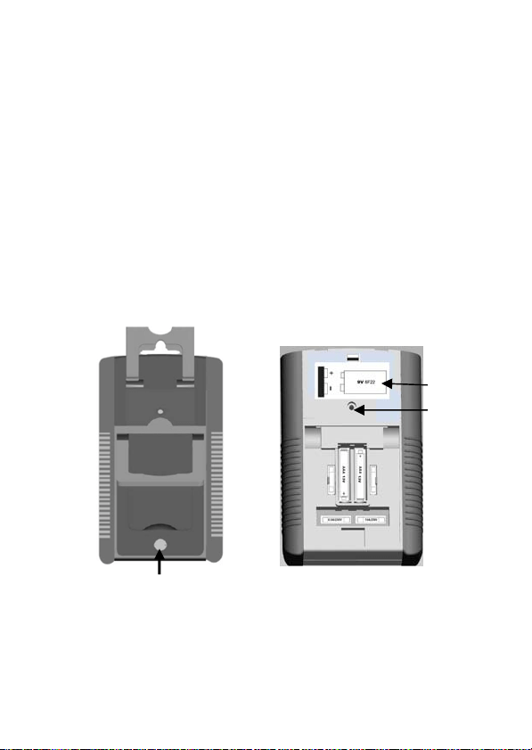
1. Battery Replacement
- 1.5V Battery (Pls. see the Picture below for reference)
1). This tester uses 2pcs AAA size 1.5V batteries which are
located under the lower battery cover together with the big
tilt device on the lower part of the rear case.
2).Note the condition of the batteries using the procedure
described above, if the battery needs to be replaced, turn
the lock by 90°degree and take off the cover of the battery
cabinet together with the big tilt device on the rear case.
3). Remove the spent batteries and replace them with a battery
of the same type. Observing polarity as indicated battery
polarity marking on the bottom of the battery compartments.
4). Replace the battery cover and turn the lock by 90°degree
again to tighten the battery cover.
- 9V Battery (Pls. see the Picture below for reference)
1). This tester uses One 9V battery which is located under the
upper battery cover together with the tilt-Hookup device on
the upper part of the rear case.
2).Note the condition of the battery using the procedure
described above, if the battery needs to be replaced, remove
the screw and open the upper cover of the battery cabinet
on the rear case.
3). Take off the spent 9V battery and replace them with a battery
of the same type. Observing polarity as indicated battery
polarity marking on the bottom of the battery compartment.
4). Replace the battery cabinet cover and tighten the screw.
2. Fuse Replacement(Pls. see the Picture below for reference)
1). When the fuse needs replacement, use only UL-Listed
0.5A/250V fuse or 10A/250V fuse identical in physical size to
the original type Φ5 x 20 mm.
13
2). Open the big lower tilt device on the rear case and then turn
the lock by 90°degree and take off the cover of the battery
cabinet together with the big tilt device.
3). The old fuses inside their holders located on the PCB can be
visible and access to be removed. Then take off the melt
fuses and install the new fuses into their original places.
The 0.5A/250V fuse is at the left side and 10A/250V fuse at
the right side.
4). Replace the battery cover and turn the lock by 90°degree
again to tighten the lower battery cover.
NOTE: 2pcs stand-by fuses are provided and located beside the
batteries under the lower battery cover with rating marked below
the fuses.
Lock for lower 1.5V
Battery Cover
Lower 1.5V Battery Cabinet
inside and Fuses Layout
Screw
Hole
9V
Battery

14
MT-2017 指針型防誤測三用電錶
操作使用說明書
特點:
本機是指針式,防誤測全保護,斜立型三用電錶(附晶體 LED 座,短
路蜂鳴及 10A 檔,及鍍金表筆)。具有以下基本特點和參數如下:
- 斜立型,兩個可調後蓋支撐架。上部支架可拉出後,向上轉動 90 度,
壓下可固定; 並附帶掛鈎設計(支撐架向上轉動 180 度伸出後蓋,
以便懸掛)。下部大支撐架可拉出以更大角度斜立。
- 後蓋下部特別設置了 1.5V 電池倉和用鎖扣固定的電池蓋,以非常
方便用戶拆卸和更換電池及保險管。
- 配置玻璃釺維環氧樹脂鍍金盤雙面電路板,日系電池,通過 CE 認證。
- 檔位切換簧片採用彈簧寶石軸承及二極體雙向限幅電路
- 具有全面的防誤測超載保護電路及速斷型保險絲多重保護
- 具有緊湊的兩側軟性防滑減振保護套
- 可測直流電壓和中間零位正負直流電壓,直流電流(最大 10A),交
流電壓,電阻,電晶體,二極體,LED,電池,短路蜂鳴, 和電容
(2000uF Max.) 等.
- 輸入阻抗:DC20Kohm /V,AC 9Kohm/V
- 直流電壓:0.1/2.5/10/50/250/1000V 六檔
- 中間零位正負直流電壓:±5V/25V 兩檔
- 直流電流:50μA/2.5m/25m/250mA/10A 五檔
- 交流電壓:10/50/250/1000V 四檔
- 電 阻:1/10/100/1K/10K 四檔
- 電
池:1.5/9V 二檔
- 電 容:C(RX1K),Max. 2,000 uF;
- 標準環境條件:23C5C, 濕度< 75% RH。
- 工作環境範圍:0C ~ 40C, 濕度< 90% RH。
- 儲存條件:-10C ~ 50C, 濕度< 80% RH。
- 電錶外形尺寸:171(長)x 108(寬)x 37(高)mm
- 電錶重量:390 克(包括電池)

15
規格表:
測試功能 檔位 準確度 說明
直流電壓
DCV
0-0.1-2.5-10-50-25
0-1000V
±3%FSD(滿刻度)
±4%FSD(1000V
檔)
輸入阻抗:20KΩ/V
超載:Max 1000V
但在 0.1V/2.5V/10V 各
檔,250V Max.
正負直流電壓
Null DCV
DC ±5V/±25V ±5% FSD.(滿刻度)
輸入阻抗:40KΩ/V;
超載:Max.250V
交流電壓 ACV
0-10-50-250V-100
0V
±4%FSD(滿刻度)
±5%FSD(1000V
檔)
頻率範圍:
40~10KHz
輸入阻抗:9KΩ/V
超載:Max.1000V
但 10V/50V 檔,250V Max.
直流電流
DCA
0-0.05-2.5-25-250
mA, 10A
±3%FSD(滿刻度)
±4%FSD(10A 檔 )
壓降:250mV
超載保護:0.5A/250V
保險絲管;在 10A 檔,超
載保護:F10A/250V, 大電
流測試時間最多 15 秒。
電阻 Ω
X1:0.2~2KΩ
(中值:20Ω)
X10:2~20KΩ
(中值:200Ω)
X100:20~200KΩ
(中值:2000Ω)
X1K:200~2MΩ
(中值:20KΩ)
X10K:2K~20MΩ
(中值:200KΩ)
±4%ofARC(弧長)
超載:最高 AC/DC250V,
最低 DC/AC50V
超載最大測試時間 5 秒。
電 容
Capacitance
C:2,000uF 最大值
參考值 使用 Rx1K 檔
電池測量
BATT Check
0~1.5V:GOOD
-?-BAD
0~9V:GOOD-?-BA
D
參考值
負載電流:270mA(1.5V 電
池), 25mA(9V 電池)
超載:最高 AC/DV250V,
最低 DC/AC 50V,
超載最大測試時間 5 秒。
三極管檢測 hFE: 0-1000 參考值 使用 Ω×10 檔
LED,
Diode Check
參考值 使用 Ω×10 檔

16
Continuity
Check
200 歐姆左右以
內,蜂鳴器會響。
超 載:最高 AC/DC 250V,
最低 DC/AC 50V 超載最
大測試時間 5 秒。
內部電源
1.5V5 號電池:2
節,
6F22.9V 矩形電
池:1 節
指針防誤測斜立型三用電錶指針閱讀參考表
測試
Tes t
量程檔位
Range Position
指標刻度讀數
Scale to read
倍數
Multiplied
電阻(歐姆)
Resistance(Ω)
×1
×10
×100
×1K
×10K
Ω ×1
×10
×100
×1000
×10000
直流電壓
(伏特)
DC Volt(V)
DC 0.1V
2.5V
10V
50V
250V
1000V
10
250
10
50
250
10
×0.01
×0.01
×1
×1
×1
×100
正負直流電壓(伏特)
Null DC Volt(V)
DC ±5V
±25V
-5-0-+5
-25-0-+25
×1
×1
直流電流
(安培)
DC Current(A)
DC 50μA
2.5mA
25mA
250mA
10A
50
250
250
250
10
×1
×0.01
×0.1
×1
×1
交流電壓
(伏特)
AC Volt(V)
AC 10V
50V
250V
1000V
10V
50
250
10
×1
×1
×1
×100
hFE Ω×10 IC/IB ×1

17
二極體 Diode
Ω×10K
×1K
×100
×10
×1
μA×1
μA×10
μA×100
mA×1
mA×10
測量注意事項:
1. 指針調零
調整零位調整器,使指針和左側的零位對齊,不必每次測量前都
調,但是在開始測量之前,指標都必須確認指標在零位上。
2. 測試棒的連接
紅色棒插“+”插孔,黑色棒插入“-COM”插孔。
3. 電錶內部電池檢查
將表棒按以上規定方式接入好,再將檔位旋鈕轉到 Rx10 檔位。
然後,將表棒的兩端短路連接。這時,檢查指針是否正常回歸零
位。若不能,則電池電力不足,應要更換新電池。
4. 量程的選擇
選擇測量檔位時,旋鈕上的“三角形”記號對準規定的適當量程。
測量工作程式:
1. 直流電壓:
用於測量電池、放大器電路、通訊設備電源、電子管和電晶體電
路偏 壓的直流電壓。6 個檔位元中的每一個檔位元標記,分別表
示該檔的最大電壓示值。
(※不確定之直流電壓,應從最大值依序向下調整量測)
2. 中值零位正負直流電壓:(不可測量任何交流電壓!)
本功能專用檢測電子電路的正負電平。通過表棒接入電路,可直
接查看刻度讀數。
注意:在此檔位時,可用歐姆電調零將指針設置在中間位置。若
無法調到中值零位,則有可能是 9V 電池電量不足。請檢查
電池。
3. 交流電壓:
用於測量商業交流電壓、交流電源電路、交流放大信號級等。4 個
檔位元中的每一個檔位元標記,分別表示該檔的最大電壓示值.(※
不確定之交流電壓,應從最大值依序向下調整量測)

18
4. 直流電流:(不可測量任何交流電流或電壓!)
用於測量直流電源控制裝置的電流消耗、電晶體電路的工作電流
等。5 個檔位元中的每一個檔位元標記,分別表示該檔的最大電流
示值。
(※不確定之直流電流,應從最大值依序向下調整量測)
注意:當在 10A 檔測試大電流時,單次測試時間不能超過 15 秒。
而且兩次測試間隔時間不少於 5 分鐘。
本機具有防誤測保護電路。可短時(5 秒內)承受低於 AC/DC 250V
的電壓衝擊,僅爆保險絲。
5. 電阻:(※此功能不能測試帶電壓電路)
測量電阻值和測試線路和線路間的連通性。5 個檔中的每一個檔
位元標記,分別表示該檔乘數。(K 即 X1000)
注意:本機在電阻檔具有防誤測保護電路。可短時(5 秒內)承
受低於 AC/DC 250V 的電壓衝擊,僅爆保險絲。
6. 連通性測試(Buzz) (※此功能不能測試帶電壓電路)
將量程選擇旋鈕置於 Buzz 檔 , 當被測電路<200ohm, 蜂鳴器鳴叫。
注意:本機在檔位元具有防誤測保護電路。可短時(5 秒內)承
受低於 AC/DC 250V 的電壓衝擊,僅爆保險絲。
7. 電池測試:(※電池能用於小的晶體管收音機,但不能用作裝的電
源。)
好電池:指針停留在綠色(GOOD)範 圍 內。電 量 不 足:指 針 停 在 “?”
尚可使用範圍內。
壞電池:指標停在紅色(BAD)區域。
注意:本機在檔位元具有防誤測保護電路。可短時(5 秒內)承
受低於 AC/DC 250V 的電壓衝擊,僅爆保險絲。
8. dB 測試:
本機測量 dB 值時,要接入表棒並串接一個 0.047μF/400V 電解電
容,然後檢視電錶讀數。
測量在 10V 檔上進行,可直接讀取 dB 刻度(-10dB~+22dB)。
測量在 50V 檔上進行時,刻度讀值要加 14dB,才是實際 dB 值。
測量在 250V 檔上進行時,刻度讀值要加 28dB。
測量在 1000V 檔上進行時,刻度讀值要加 40dB。

19
例如,在 1000V 檔上最大可測 dB 值是 22+40=62dB。
9. hFE(直流放大倍數)和發光二極體(LED)測試:
將量程選擇旋鈕置於“OHM”檔上之 X10 檔
hFE 測試:
(1) 調節 0 Ω 調整器使指針和零位對齊-將電晶體的三個管腳直接
插入面板上的 hFE 端座。
(※注意區分電晶體的類別“PNP”和“NPN”)
(2) 在 hFE 刻度讀出顯示值,所讀之值是 IC/IB,即被測體的直流
放大倍數。
LED 測試:
(1) 將 LED 的兩個腳按正負極性直接插入面板上的 LED 的“+”,“-”
兩個端座。
(2) 檢查 LED 是否正常發光。
10. 二極體測試:
(1) 將量程選擇旋鈕置於“Ω”檔上有選擇的量程位置,X10K 用於
0~60μ A 測試,X1K 用於 0~150μ A,X100 用於 0~1.5m A,
X10 於 0~15mA,X1 用於
0~150mA 測試。
(2) 將電錶與二極體連接測 IF(正向電流),將電錶的“COM”端與
二極體陽極相連,“+”端與二極體陰極相連,對於 IR(反向電
流)測試連接方法和 IF 相反。
(3) 在 LI 刻度線讀出 IF 或 IR
(4) 在測試 IF 或 IR 同時在 LV 刻度上,讀出二極體正向(反向)電壓。
11. 電容測試:
注意:檢測前,須將電容放電並將電錶調零。(※此功能不能測
試帶電壓電路)
a.將電錶量程選擇旋鈕置於“Ωx1k”檔。
b.用表棒連接電容,並注意“+”,“-”極性。
c.觀察指標偏轉最大時,電錶刻度板上紅色 C 刻度。

20
常見問題故障及處理
若用戶在使用中,發現本機出現一些普通常見問題故障,可參照下表
自行進行分析處理:
問題和故障 原因和處置
指針無反應,不動 表棒是否接觸良好? 內部保險管是否
燒斷?
內部電池是否正確裝好,並接觸到位?
(參閱有關電池和保險管更換說明)
指針指示異常 檔位量程是否選擇正確? 交流和直流
模式是否使用正確?
內部電池是否電量不足?(參閱有關電
錶內部電池檢查說明)
指針無法正常歸零
位
內部電池是否接觸良好?是否電量不
足?(參閱有關電錶內部電池檢查說明)
內部機芯處的遊絲是否並圈?可試用力
將本機甩動幾下或在手中拍擊幾下後,
看是否恢復正常。
DC10A 檔不能工作 表棒是否接觸良好,正確接入?
內部 10A 保險管是否裝好或燒斷?
(參閱有關保險管更換說明)
日常維修
維修更換電錶內部電池和保險絲管時,必須將表棒從電錶上移調,並
切斷電源。
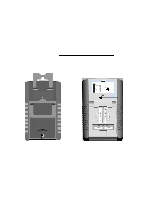
1). 1.5V 電池更換:(參閱下圖)
打開電錶後面的下部大支撐架,將下部的電池倉後蓋的鎖扣旋轉 90
度,既可將電池倉後蓋連支撐架卸下,然後從電池座中拿出不好的
電池。再將新的同規格電池放入原位,並注意電池的正負極性。然
後,蓋上後蓋並將鎖扣旋轉 90 度而鎖住。
2). 9V 電池更換:(參閱下圖)
打開電錶的上部電池倉後蓋,從電池座中拿出不好的電池。再將新的

21
同規格電池放入原位,並注意電池的正負極性,然後,蓋上後蓋並擰
緊螺釘。
3). 保險絲管更換:(參閱下圖)
打開電錶後面的下部大支撐架,將下部的電池倉後蓋的鎖扣旋轉 90
度,既可將電池倉後蓋連支撐架卸下。 即可看到電路板上的兩個並
列保險管(左邊的為 0.5A/250V, 右邊為 10A/250V), 從保險絲座中拿
出不好的保險絲管。再將新保險絲管(0.5A/250V 或 10A/250V,
Φ5*20mm)換上。必須用同規格 UL 認證的保險絲管。 然後,蓋上
後蓋並將鎖扣旋轉 90 度而鎖住。
(本電錶的下部電池倉的左右兩邊一般各設有 1 個備用保險絲管)。
1.5V 電池蓋鎖扣
1.5V 電池倉和保險管位置
螺絲孔
9V 電池
位置

22
MT-2017 指针型防误测三用电表
操作使用说明书
特点:
本机是指针式,防误测全保护,斜立型三用电表(附晶体 LED 座,短
路蜂鸣及 10A 档,及镀金表笔)。具有以下基本特点和参数如下:
- 斜立型,两个可调后盖支撑架。上部支架可拉出后,向上转动 90 度,
压下可固定; 并附带挂钩设计(支撑架向上转动 180 度伸出后盖,
以便悬挂)。下部大支撑架可拉出以更大角度斜立。
- 后盖下部特别设置了 1.5V 电池仓和用锁扣固定的电池盖,以非常
方便用户拆卸和更换电池及保险管。
- 配置玻璃钎维环氧树
脂镀金盘双面电路板,日系电池,通过 CE 认证。
- 档位切换簧片采用弹簧宝石轴承及二极管双向限幅电路
- 具有全面的防误测超载保护电路及速断型保险丝多重保护
- 具有紧凑的两侧软性防滑减振保护套
- 可测直流电压和中间零位正负直流电压,直流 电流(最 大 10A),交
流电压,电阻,晶体管,二极管,LED,电池,短路蜂鸣, 和电容
(2000uF Max.) 等.
- 输入阻抗:DC20Kohm /V,AC 9Kohm/V
- 直流电压:0.1/2.5/10/50/250/1000V
六檔
- 中间零位正负直流电压:±5V/25V 两檔
- 直流电流:50μA/2.5m/25m/250mA/10A 五檔
- 交流电压:10/50/250/1000V 四檔
- 电 阻:1/10/100/1K/10K 四檔
- 电 池:1.5/9V 二檔
- 电 容:C(RX1K),Max. 2,000 uF;
- 标准环境条件:23C5C, 湿度< 75% RH。
- 工作环境范围:0C ~ 40C, 湿度< 90% RH。
- 储存条件:-10C ~ 50C, 湿度
< 80% RH。
- 电表外形尺寸:171(长)x 108(宽)x 37(高)mm
- 电表重量:390 克(包括电池)

23
规格表:
测试功能 檔位 准确度 说明
直流电压
DCV
0-0.1-2.5-10-50-25
0-1000V
±3%FSD(满刻度)
±4%FSD(1000V
檔)
输入阻抗:20KΩ/V
超载:Max 1000V
但在 0.1V/2.5V/10V 各檔,
250V Max.
正负直流电压
Null DCV
DC ±5V/±25V ±5% FSD.(满刻度)
输入阻抗:40KΩ/V;
超载:Max.250V
交流电压 ACV
0-10-50-250V-100
0V
±4%FSD(满刻度)
±5%FSD(1000V
檔)
频率范围:
40~10KHz
输入阻抗:9KΩ/V
超载:Max.1000V
但 10V/50V 檔,250V Max.
直流电流
DCA
0-0.05-2.5-25-250
mA, 10A
±3%FSD(满刻度)
±4%FSD(10A 檔 )
压降:250mV
超载保护:0.5A/250V
保险丝管;在 10A 檔,超
载保护:F10A/250V, 大电
流测试时间最多 15 秒。
电阻 Ω
X1:0.2~2KΩ
(中值:20Ω)
X10:2~20KΩ
(中值:200Ω)
X100:20~200KΩ
(中值:2000Ω)
X1K:200~2MΩ
(中值:20KΩ)
X10K:2K~20MΩ
(中值:200KΩ)
±4%ofARC(弧长)
超载:最高 AC/DC250V,
最低 DC/AC50V
超载最大测试时间 5 秒。
电 容
Capacitance
C:2,000uF 最大值
参考值 使用 Rx1K 檔
电池测量
BATT Check
0~1.5V:GOOD
-?-BAD
0~9V:GOOD-?-BA
D
参考值
负载电流:270mA(1.5V 电
池), 25mA(9V 电池)
超载:最高 AC/DV250V,
最低 DC/AC 50V,
超载最大测试时间 5 秒。
三极管检测 hFE: 0-1000 参考值 使用 Ω×10 檔
LED,
Diode Check
参考值 使用 Ω×10 檔

24
Continuity
Check
200 歐姆左右以内,
蜂鸣器会响。
超载:最高 AC/DC 250V,
最低 DC/AC 50V 超载最
大测试时间 5 秒。
内部电源
1.5V5 号电池:2 节,
6F22.9V 矩形电池:
1 节
指针防误测斜立型三用电表指针阅读参考表
测试
Tes t
量程檔位
Range Position
指标刻度读数
Scale to read
倍数
Multiplied
电阻(歐姆)
Resistance(Ω)
×1
×10
×100
×1K
×10K
Ω ×1
×10
×100
×1000
×10000
直流电压
(伏特)
DC Volt(V)
DC 0.1V
2.5V
10V
50V
250V
1000V
10
250
10
50
250
10
×0.01
×0.01
×1
×1
×1
×100
正负直流电压(伏特)
Null DC Volt(V)
DC ±5V
±25V
-5-0-+5
-25-0-+25
×1
×1
直流电流
(安培)
DC Current(A)
DC 50μA
2.5mA
25mA
250mA
10A
50
250
250
250
10
×1
×0.01
×0.1
×1
×1
交流电压
(伏特)
AC Volt(V)
AC 10V
50V
250V
1000V
10V
50
250
10
×1
×1
×1
×100
hFE Ω×10 IC/IB ×1

25
二极管 Diode
Ω×10K
×1K
×100
×10
×1
μA×1
μA×10
μA×100
mA×1
mA×10
测量注意事项:
1. 指针调零
调整零位调整器,使指针和左侧的零位对齐,不必每次测量前都
调,但是在开始测量之前,指标都必须确认指标在零位上。
2. 测试棒的连接
红色棒插“+”插孔,黑色棒插入“-COM”插孔。
5. 电表内部电池检查
将表棒按以上规定方式接入好,再将档位旋钮转到 Rx10 檔位。
然后,将表棒的两端短路连接。这时,检查指针是否正常回归零
位。若不能,则电池电力不足,应要更换新电池。
6. 量程的
选择
选择测量档位时,旋钮上的“三角形”记号对准规定的适当量程。
测量工作程序:
1. 直流电压:
用于测量电池、放大器电路、通讯设备电源、电子管和晶体管电
路偏 压的直流电压。6 个文件位中的每一个文件位标记,分别表
示该文件的最大电压示值。
(※不确定之直流电压,应从最大值依序向下调整量测)
2. 中值零位正负直流电压:(不可测量任何交流电压!)
本功能专用检测电子电路的正负电平。通过表棒接入电路,可直
接查看刻度
读数。
注意:在此档位时,可用歐姆电调零将指针设置在中间位置。若
无法调到中值零位,则有可能是 9V 电池电量不足。请检查
电池。
3. 交流电压:
用于测量商业交流电压、交流电源电路、交流放大信号级等。4 个
文件位中的每一个文件位标记,分别表示该文件的最大电压示
值.(※不确定之交流电压,应从最大值依序向下调整量测)

26
4. 直流电流:(不可测量任何交流电流或电压!)
用于测量直流电源控制装置的电流消耗、晶体管电路的工作电流
等。5 个文件位中的每一个文件位标记,分别表示该文件的最大电
流示值。
(
※
不确定之直流电流,应从最大值依序向下调整量测)
注意:当在 10A 档测试大电流时,单次测试时间不能超过 15 秒。
而且两次测试间隔时间不少于 5 分钟。
本机具有防误测保护电路。可短时(5 秒内)承受低于 AC/DC 250V
的电压冲击,仅爆保险丝。
5. 电阻:(
※此功能不能测试带电压电路)
测量电阻值和测试线路和线路间的连通性。5 个文件中的每一个
文件位标记,分别表示该文件乘数。(K 即 X1000)
注意:本机在电阻文件具有防误测保护电路。可短时(5 秒内)
承受低于 AC/DC 250V 的电压冲击,仅爆保险丝。
6. 连通性测试(Buzz) (
※
此功能不能测试带电压电路)
将量程选择旋钮置于 Buzz 文件,当被测电路<200ohm, 蜂鸣器鸣叫。
注意:本机在文件位具有防误测保护电路。可短时(5 秒内)承
受低于 AC/DC 250V 的电压冲击,仅爆保险丝。
7. 电池测试:(
※电池能用于小的晶体管收音机,但不能用作装的电
源。)
好电池:指针停留在绿色(GOOD)范围内。电量不足:指针停在“?”
尚可使用范围内。
坏电池:指针停在红色(BAD)区域。
注意:本机在文件位具有防误测保护电路。可短时(5 秒内)承
受低于 AC/DC 250V 的电压冲击,仅爆保险丝。
8. dB 测试:
本机测量 dB 值时,要接入表棒并串接一个 0.047μF/400V 电解电
容,然后检视电表读数。
测量在 10V 档
上进行,可直接读取 dB 刻度(-10dB~+22dB)。
测量在 50V 档上进行时,刻度读值要加 14dB,才是实际 dB 值。
测量在 250V 档上进行时,刻度读值要加 28dB。
测量在 1000V 档上进行时,刻度读值要加 40dB。

27
例如,在 1000V 档上最大可测 dB 值是 22+40=62dB。
9. hFE(直流放大倍数)和发光二极管(LED)测试:
将量程选择旋钮置于“OHM”檔上之 X10 檔
hFE 测试:
(3) 调节 0 Ω 调整器使指针和零位对齐-将晶体管的三个管脚直接
插入面板上的 hFE 端座。
(
※注意区分晶体管的类别“PNP”和“NPN”)
(4) 在 hFE 刻度读出显示值,所读之值是 IC/IB,即 被 测体的直流
放大倍数。
LED 测试:
(3) 将 LED 的两个脚按正负极性直接插入面板上的 LED 的“+”,“-”
两个端座。
(4) 检查 LED 是否正常发光。
10. 二极管测试:
(5) 将量程选择旋钮置于“Ω”档上有选择的量程位置,X10K 用于
0~60μ A 测试,X1K 用于 0~150μ A,X100 用于 0~1.5m A,
X10 于 0~15mA,X1 用于 0~150mA 测试。
(6)
将电表与二极管连接测 IF(正向电流),将电表的“COM”端与
二极管阳极相连,“+”端与二极管阴极相连,对于 IR(反向电
流)测试连接方法和 IF 相反。
(7) 在 LI 刻度线读出 IF 或 IR
(8) 在测试 IF 或IR 同时在 LV 刻度上,读出二极管正向(反向)电压。
11. 电容测试:
注意:检测前,须将电容放电并将电表调零。(
※此功能不能测
试带电压电路)
a.将电表量程选择旋钮置于“Ωx1k”檔。
b.用表棒连接电容,并注意“+”,“-”极性。
c.观察指标偏转最大时,电表刻度板上红色 C 刻度。

28
常见问题故障及处理
若用户在使用中,发现本机出现一些普通常见问题故障,可参照下表
自行进行分析处理:
问题和故障 原因和处置
指针无反应,不动 表棒是否接触良好? 内部保险管是否
烧断?
内部电池是否正确装好,并接触到位?
(参阅有关电池和保险管更换说明)
指针指示异常 档位量程是否选择正确? 交流和直流
模式是否使用正确?
内部电池是否电量不足?(参阅有关电
表内部电池检查说明)
指针无法正常归零
位
内部电池是否接触良好?是否电量不
足?(参阅有关电表内部电池检查说明)
内部机芯处的游丝是否并圈?可试用力
将本机甩动几下或在手中拍击几下后,
看是否恢复正常。
DC10A 檔不能工作 表棒是否接触良好,正确接入?
内部 10A 保险管是否装好或烧断?
(参阅有关保险管更换说明)
日常维修
维修更换电表内部电池和保险丝管时,必 须将表棒从电表上移调,并
切断电源。
1). 1.5V 电池更换:(参阅下图)
打开电表后面的下部大支撑架,将下部的电池仓后盖的锁扣旋转 90
度,既可将电池仓后盖连支撑架卸下,然后从电池座中拿出不好的
电池。再将新的同规格电池放入原位,并注意电池的正负极性。然
后,盖上后盖并将锁扣旋转 90 度而锁住。
2). 9V 电池更换:(参阅下图)
打开电表的上部电池仓后盖,从电池座中拿出不好的电池。再将新的
29
同规格电池放入原位,并注意电池的正负极性,然后,盖上后盖并拧
紧螺钉。
3). 保险丝管更换:(参阅下图)
打开电表后面的下部大支撑架,将下部的电池仓后盖的锁扣旋转 90
度,既可将电池仓后盖连支撑架卸下。 即可看到电路板上的两个并
列保险管(左边的为 0.5A/250V, 右边为 10A/250V), 从保险丝座中拿
出不好的保险丝管。再将新保险丝管(0.5A/250V 或 10A/250V,
Φ5*20mm)换上。必须用同规格 UL 认证的保险丝管。 然后,盖上
后盖并将锁扣旋转 90 度而锁住。
(本电表的下部电池仓的左右两边一般各设有 1 个备用保险丝管)。
1.5V 电池盖锁扣
1.5V 电池仓和保险管位置
螺丝孔
9V 电池
位置

30
中国地区产品保固卡
购买日期
公司名称
联络电话
电子邮箱
联络地址
店章
产品型号 □ MT-2017-C
※ 在正常使用情况下,自原购买日起 12 个月免费维修保证(不含
耗材、消耗品)。
※ 产品保固卡需盖上店章、日期章,其保固效力始生效。
※ 本卡请妥善保存,如需维修服务时,请出示本卡以为证明。
※ 保固期满后,属调整、保养或是维修性质之服务,则酌收检修工
时费用。若有零件需更换,则零件费另计。
产品保固说明
保固期限内,如有下列情况者,维修中心则得酌收材料成本或修
理费(由本公司维修人员判定):
• 对产品表面的损伤,包括外壳裂缝或刮痕
• 因误用、疏忽、不当安装或测试,未经授权打开产品修理,
修改产品或者任何其他超出预期使用范围的原因所造成的
损害
• 因事故、火灾、电力变化、其他危害,或自然灾难所造成的
损害。
非服务保证内容:
• 机件本体外之消耗品:如电池...等消耗品
• 机件本体之外之附配件:如耳机麦克风,电源供应器,记忆
卡,CD 等附配件。
三.超过保证期限之检修或服务,虽未更换零件,将依公司保固维
修政策酌收服务费。
服务电话: 0755 83692415 / 83692986 /83246594 / 83247554
服务传真: 0755 83692143

31
寶工實業股份有限公司
PROKIT’S INDUSTRIES CO., LTD
http://www.prokits.com.tw
Email: [email protected]
©2015 Prokit’s Industries Co., LTD. All rights reserved 2015001(C)