
NEC Display Solutions of America, Inc.
V801 Installation Guide
80” LCD Display Rev 1.1
www.necdisplay.com V801 Page 1 of 8
Contents:
Product Description and Notes Page 1
Tilt Angle and Rotation
Page 1
Ventilation Requirements
Page 2
Display Dimensions
Front, Top, Right Side, Left Side Page 3
Rear & Bottom
Page 4
Optional Table Top Stand Dimensions
Page 5
Optional Speaker Dimensions
Page 6
Display with Optional Wall Mount Kit
Page 7
Input Panels
Page 8
Control Codes Page 8
Product Description:
Type: LCD Display
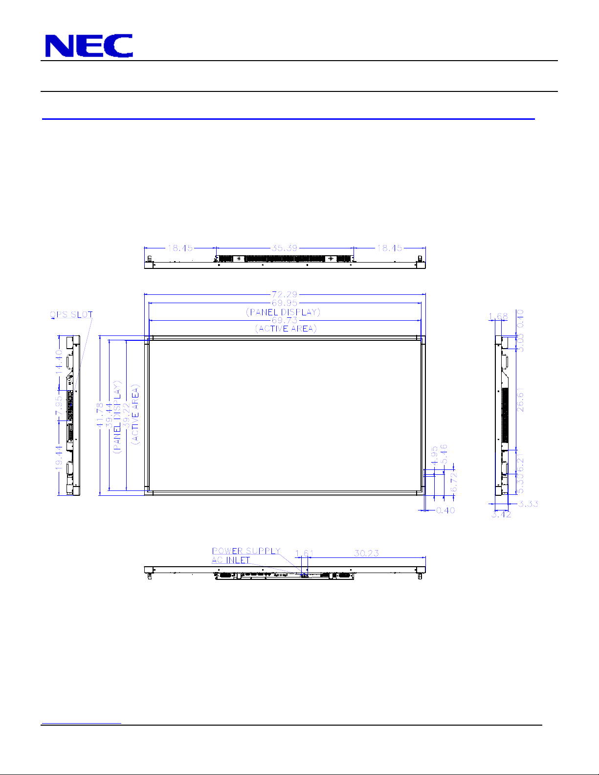
Resolution: 1920 x 1080 Dimensions without stand: 72.3” (W) x 41.8” (H) x 3.4” (D)
Aspect Ratio: 16:9 Dimensions with stand: 72.3”(W) x 43.3”(H) x 23.9”(D)
FCC: Class B Weight without stand: 132.3 lbs
Power Consumption: 230W (typ) Weight with stand: 142.5 lbs
BTU’s: 784.79 BTU/hour
NOTES:
This document is intended to be used as a reference guide to supply useful information for a design or installation. It is not
intended to be a step-by step procedure for installation.
Any ceilings or walls must be strong enough to support the monitor and the installation must be in accordance with any local
building codes. All mounts should make secure contact to wood studs.
4:3 sources can be displayed on the 16:9 screen in either normal aspect ratio with bars on the left or right, or stretched horizontally
to fill the screen using the menus (see “Aspect Modes” in menus and user manual).
Distances are in inches, for millimeters multiply by 25.4.
Distances may vary ±5%.
Tilt Angle and Rotation:
Below is the maximum angle the monitor can be tilted. Note that the monitor can only be tilted in the landscape position.
NEC Display Solutions of America, Inc.
V801 Installation Guide
80” LCD Display Rev 1.1
www.necdisplay.com V801 Page 2 of 8
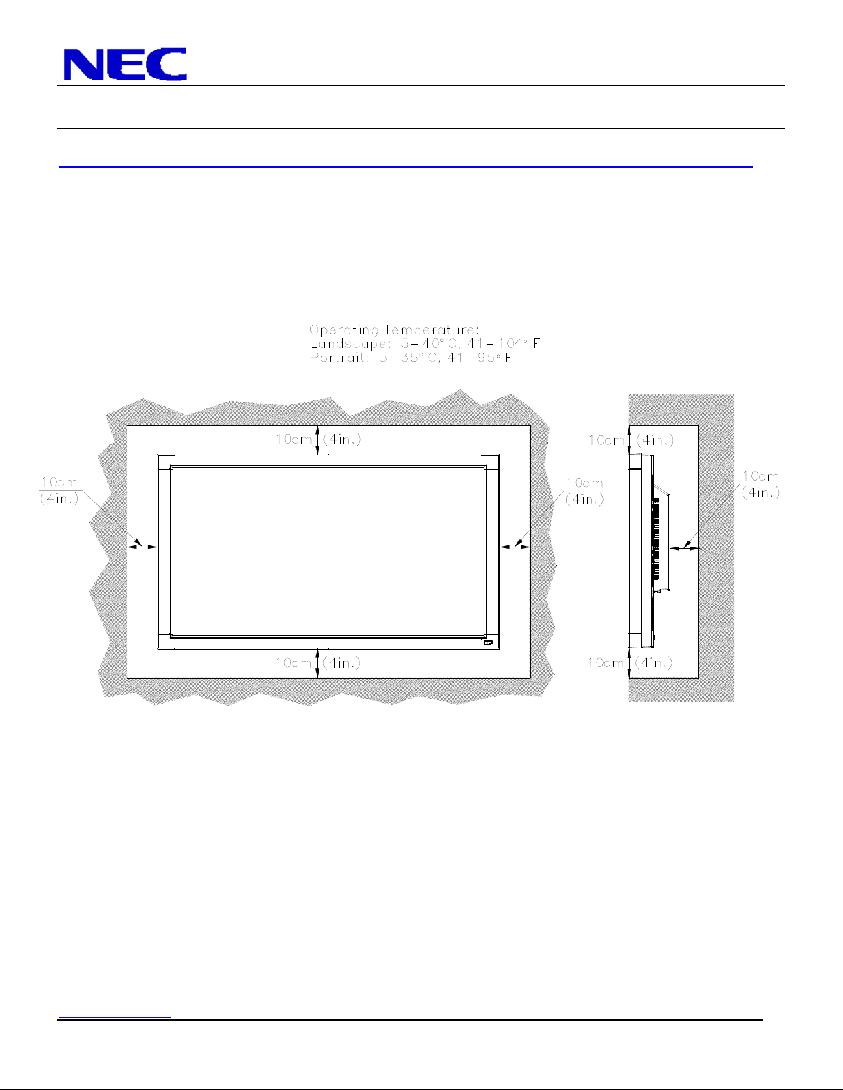
Ventilation Requirements:
Dimensions below are minimum required for proper ventilation.
NOTE:
The ventilation space should not be covered or closed off at the front of the opening. If for some reason the opening needs to be
covered, other means of ventilation will need to be incorporated into the design. Contact NEC for design review and
recommendations.
NEC Display Solutions of America, Inc.
V801 Installation Guide
80” LCD Display Rev 1.1
www.necdisplay.com V801 Page 3 of 8
Display dimensions:

NEC Display Solutions of America, Inc.
V801 Installation Guide
80” LCD Display Rev 1.1
www.necdisplay.com V801 Page 4 of 8
Display dimensions (cont.):
NEC Display Solutions of America, Inc.
V801 Installation Guide
80” LCD Display Rev 1.1
www.necdisplay.com V801 Page 5 of 8
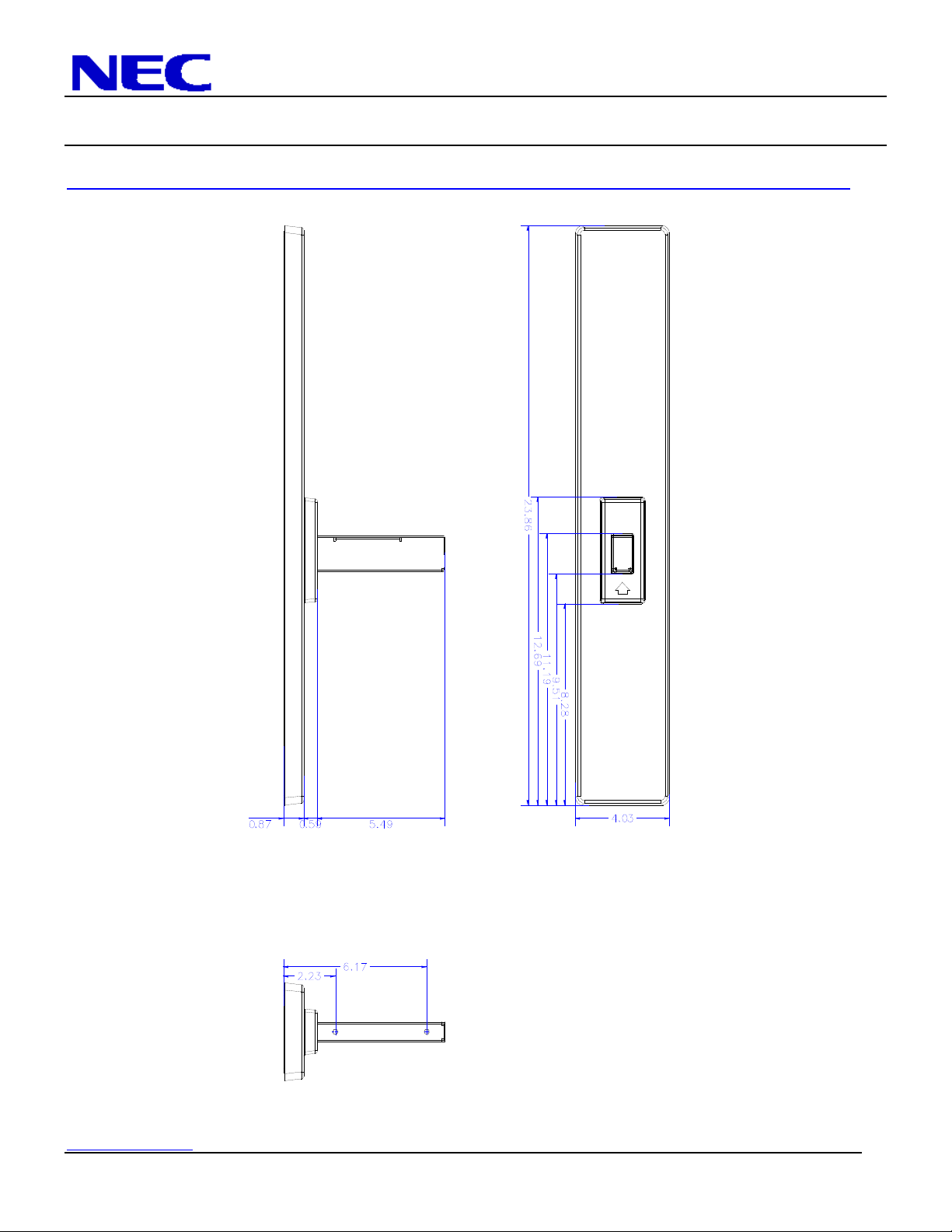
Table Top Stand Dimensions (ST-801):
NEC Display Solutions of America, Inc.
V801 Installation Guide
80” LCD Display Rev 1.1
www.necdisplay.com V801 Page 6 of 8
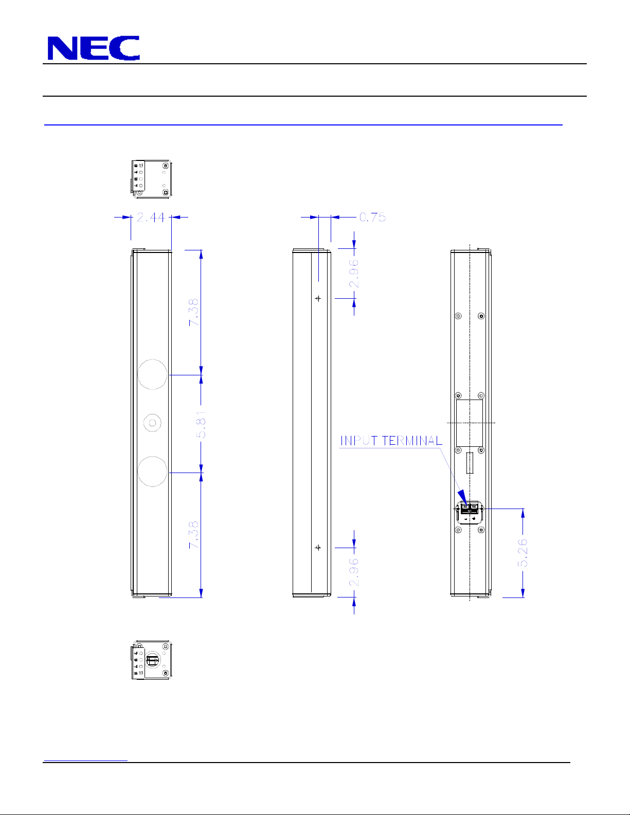
Optional Speaker Dimensions including holder (SP-RM1):
NEC Display Solutions of America, Inc.
V801 Installation Guide
80” LCD Display Rev 1.1
www.necdisplay.com V801 Page 7 of 8
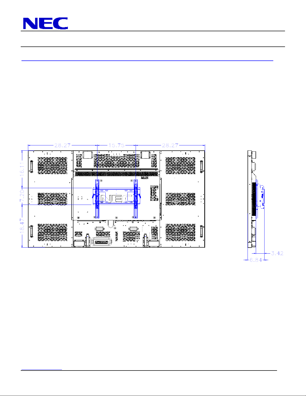
Dimensions with Optional Wall Mount Kit (WMK-3257):
NEC Display Solutions of America, Inc.
V801 Installation Guide
80” LCD Display Rev 1.1
www.necdisplay.com V801 Page 8 of 8
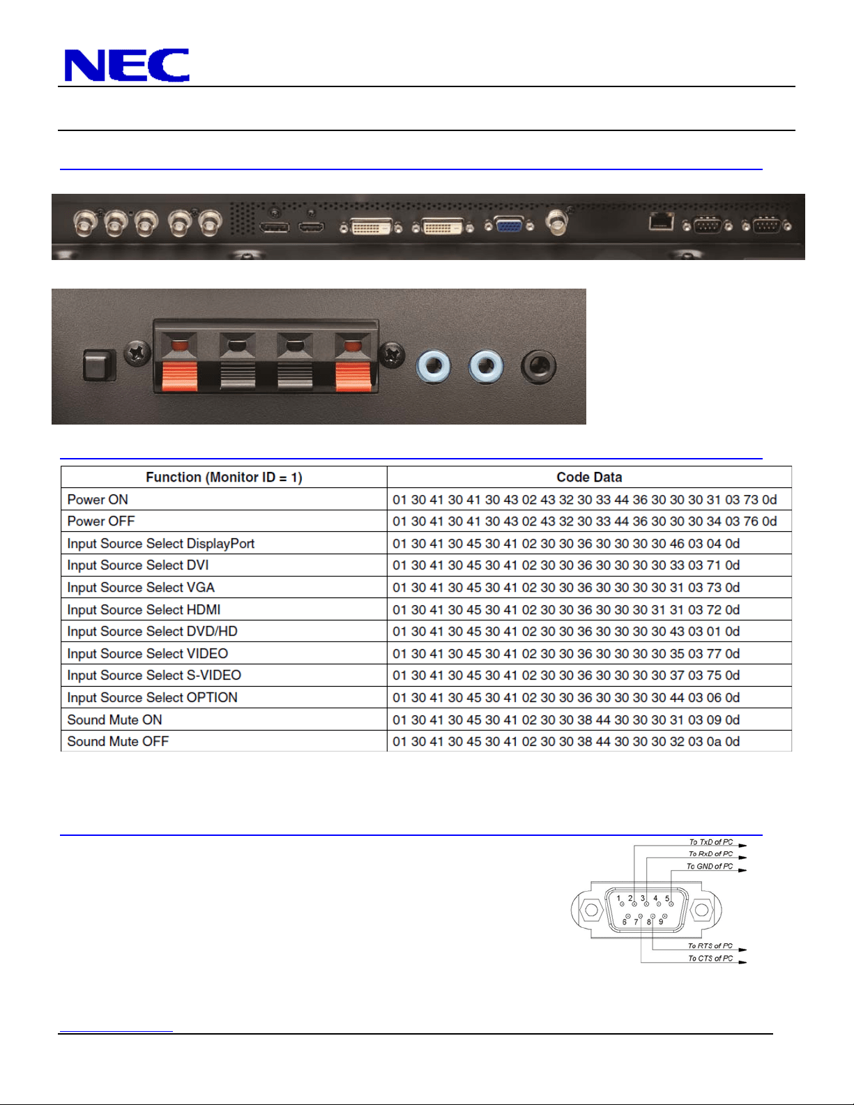
Input Panel:
Bottom
Side (Rotated)
Control Codes:
NOTE: Contact your NEC rep for codes not listed.
NOTE: Use a cross/reverse/null modem cable.
Cable Connection
Communication Protocol:
Interface: RS-232C Parity: None
Communication: Asynchronous Stop Bit: 1 bit
Baud Rate: 9600 bps Communication Code: Hex
Data Length: 8 bits PC Control Connector (D-Sub 9Pin)
NOTE:
If so desired, jumper “Request to send” and “Clear to Send” together on both ends of the cable to simplify cable connection. These
connections are not required. The only connections required are pins 2 (RxD), 3 (TxD) and 5 (GND).