LCD Projector
Thank you for purchasing this Panasonic product.
■ Before operating this product, please read the instructions (Basic Guide / Functional Manual) carefully and
save this manual for future use.
■ Before using your projector, be sure to read “Read this rst!” (
pages
6
to
13).
Operating Instructions
Functional Manual
ENGLISH
TQBJ0466
Model No.
PT-AE8000U

2 - ENGLISH
Trademarks
• Apple and iPhone are the trademarks of Apple Inc. registered in the United States and other countries.
• VGA and XGA are trademarks of International Business Machines Corporation.
• SVGA is a registered trademark of the Video Electronics Standards Association.
• HDMI, the HDMI logo and High-Denition Multimedia Interface is a trademark or registered trademark of HDMI Licensing
LLC.
• The font used in the on-screen displays is a Ricoh bitmap font, which is manufactured and sold by Ricoh Company, Ltd.
• RealD 3D is a trademark of RealD Inc.
• Other names, company names or product names used in these operating instructions are the trademarks or registered
trademarks of their respective holders.
Please note that the operating instructions do not include the ® and TM symbols.
Illustrations in these operating instructions
• Note that illustrations of the projector may differ from the ones you actually see.
Page references
• In these instructions, references to pages are indicated as: (
page 00).
Term
• In these instructions, the “Wireless remote control unit” accessory is referred to as the “Remote control”.
ENGLISH - 3
Features of the ProjectorFeatures of the Projector
Equipped with 3D (3D motion
remaster, 3D double-speed
drive technology, and 2D to 3D
conversion technology) that help
enjoy diverse content in high picture
quality.
Brightness and contrast have been
upgraded with the introduction of
the newly developed high intensity
lamps and optical system.
Equipped with the new parallax
adjustment monitoring function for
simplifying the adjustment of lateral
parallax during the input of 3D
image signals, and the new gamma
adjustment function for enabling
ner gamma adjustment.
Real Live 3D Experience
Upgraded brightness and
contrast
Further enhanced
adjustment function
Quick StepsQuick Steps
See the relevant page for details.
1. Set up your projector
(
page 21)
2. Connect the projector to
other devices
(
page 26)
3. Connect the power cord
(
page 28)
4. Switch on the projector
(
page 29)
5. Select the input signal
(
page 31)
6. Adjust the image
(
page 31)

4 -
ENGLISH
Important
Information
Preparation Getting Started Basic Operation Settings Maintenance Appendix
Contents
Be sure to read “Read this rst!”. (
pages
6
to
13)
Important Information
Read this rst! .....................................................6
Precautions for use ......................................... 14
Cautions when transporting..........................................14
Cautions when installing ...............................................14
Cautions on use ............................................................16
About disposal ...............................................................16
Accessories ...................................................................17
Optional accessories ....................................................17
Preparation
About your projector ....................................... 18
Remote control ..............................................................18
Projector body ...............................................................19
Getting Started
Setting up .......................................................... 21
Projection method .........................................................21
Parts for ceiling mount (optional) ..................................21
Projection related ..........................................................22
Front adjustable feet and throwing angle ....................23
Lens shift and positioning .............................................24
Connections ...................................................... 26
Before connecting to the projector ...............................26
Connecting example: COMPONENT IN/S-VIDEO IN/
VIDEO IN .......................................................................26
Connecting example: HDMI IN/COMPUTER IN .........27
3D IR Transmitter (optional accessory) connection ....27
Basic Operation
Switching the projector on/off ....................... 28
Power cord ....................................................................28
Power indicator .............................................................28
Switching on the projector ............................................29
Switching off the power .................................................30
Projecting an image ......................................... 31
Selecting the input signal ..............................................31
Adjusting the image ......................................................31
Remote control operation ............................... 32
Managing the lens control settings ..............................32
Selecting the picture mode ...........................................32
Adjusting the picture .....................................................32
Loading a saved setting ................................................33
Displaying the [VIERA LINK] menu ..............................33
Displaying the waveform monitor .................................33
Resetting to the default settings ...................................33
Submenu .......................................................................34
Switching the input signal .............................................34
Using the <FUNCTION> button .........................................34
Displaying the [3D SETTINGS] menu .........................34
Viewing 3D Images .......................................... 35
About viewing 3D images .............................................35
Communication range of a 3D IR Transmitter and 3D
Eyewear ........................................................................36
Cautions when using 3D Eyewear ...............................36
Settings
Menu navigation ............................................... 37
Navigating through the menu .......................................37
Menu list ........................................................................38
[PICTURE] menu .............................................. 40
[PICTURE MODE] ........................................................40
[CONTRAST] ................................................................40
[BRIGHTNESS] ............................................................40
[COLOR] ........................................................................40
[TINT] .............................................................................40
[COLOR TEMPERATURE] ..........................................41
[SHARPNESS] ..............................................................41
[DYNAMIC IRIS] ...........................................................41
[WAVEFORM MONITOR] ............................................41
[SPLIT ADJUST] ...........................................................44
[ADVANCED MENU] ....................................................45
[PICTURE MEMORY] ..................................................58
SIGNAL MODE .............................................................59
[POSITION] menu ............................................. 60
[H-POSITION] ...............................................................60
[V-POSITION] ...............................................................60
[DOT CLOCK] ...............................................................60

ENGLISH
- 5
Important
Information
PreparationGetting StartedBasic OperationSettingsMaintenanceAppendix
Contents
[CLOCK PHASE] ..........................................................60
[ASPECT] ......................................................................61
[WSS] ............................................................................63
[OVER SCAN] ...............................................................63
[KEYSTONE] ................................................................63
[AUTO SETUP] .............................................................63
[3D SETTINGS] menu ...................................... 64
[SCREEN SIZE] ............................................................64
[3D INPUT FORMAT] ...................................................64
[LEFT/RIGHT SWAP] ...................................................66
[3D PICTURE BALANCE] ............................................66
[2D TO 3D] ....................................................................69
[3D EYEWEAR BRIGHTNESS] ..................................70
[3D IR TRANSMITTER]................................................70
[3D VIEWING MONITOR] ............................................71
[3D MOTION REMASTER] ..........................................72
[3D SAFETY PRECAUTIONS] ....................................72
[LENS CONTROL] menu ................................. 73
[ZOOM/FOCUS] ...........................................................73
[LENS MEMORY LOAD] ..............................................73
[LENS MEMORY SAVE] ..............................................74
[LENS MEMORY EDIT]................................................74
[AUTO SWITCHING] ....................................................75
[H-AREA POSITION] ....................................................76
[V-AREA POSITION] ....................................................76
[LEFT MASKING AREA] ..............................................76
[RIGHT MASKING AREA] ............................................76
[UPPER MASKING AREA] ..........................................76
[LOWER MASKING AREA] .........................................76
[PROCESSING MESSAGE] ........................................76
[OPTION] menu ................................................ 77
[ON-SCREEN DISPLAY] ..............................................77
[BACK COLOR] ............................................................77
[STARTUP LOGO] ........................................................78
[AUTO SEARCH] ..........................................................78
[HDMI SIGNAL LEVEL] ................................................78
[FRAME RESPONSE] ..................................................78
[PROJECTION METHOD] ...........................................78
[TRIGGER 1/2 SETTING] ............................................79
[SLEEP] .........................................................................80
[HIGH ALTITUDE MODE] ............................................80
[LAMP POWER] ...........................................................81
[FUNCTION BUTTON] .................................................81
[VIERA LINK SETTINGS] .............................................81
[OTHER FUNCTIONS] .................................................83
[TEST PATTERN] .........................................................83
[LAMP RUNTIME] ........................................................83
[INITIALIZE ALL] ...........................................................84
Maintenance
TEMP and LAMP Indicators ............................ 85
Managing the indicated problems ................................85
Care and replacement ..................................... 87
Before cleaning the projector /
replacing components ..................................................87
Cleaning the projector ...................................................87
Component replacement ..............................................89
Troubleshooting ............................................... 94
Ceiling mount bracket safeguards ................ 95
Appendix
Using VIERA Link ............................................. 96
Summary of VIERA Link features ................................96
VIERA Link “HDAVI Control” ........................................97
Technical information .................................... 100
List of compatible signals ...........................................100
Supported 3D video signal list ....................................101
Serial terminal .............................................................102
Specications ................................................. 106
Dimensions .................................................................108
Index ................................................................. 109
Read this rst!
6 -
ENGLISH
Important
Information
Read this rst!
WARNING: TO REDUCE THE RISK OF FIRE OR ELECTRIC SHOCK, DONOT EXPOSE THIS PRODUCT
TO RAIN OR MOISTURE.
Power
Supply:
This Projector is designed to operate on 100 V - 240 V, 50 Hz/60 Hz AC, house current only.
CAUTION: The AC power cord which is supplied with the projector as an accessory can only be used for
power supplies up to 125 V. If you need to use higher voltages or currents than this, you will need
to obtain a separate 250 V power cord. If you use the accessory cord in such situations, re
may
result.
The lightning ash with arrowhead symbol, within an equilateral triangle, is intended to alert the
user to the presence of uninsulated “dangerous voltage” within the product’s enclosure that may
be of sufcient magnitude to constitute a risk of electric shock to persons.
The exclamation point within an equilateral triangle is intended to alert the user to the presence of
important operating and maintenance (servicing) instructions in the literature accompanying the
product.
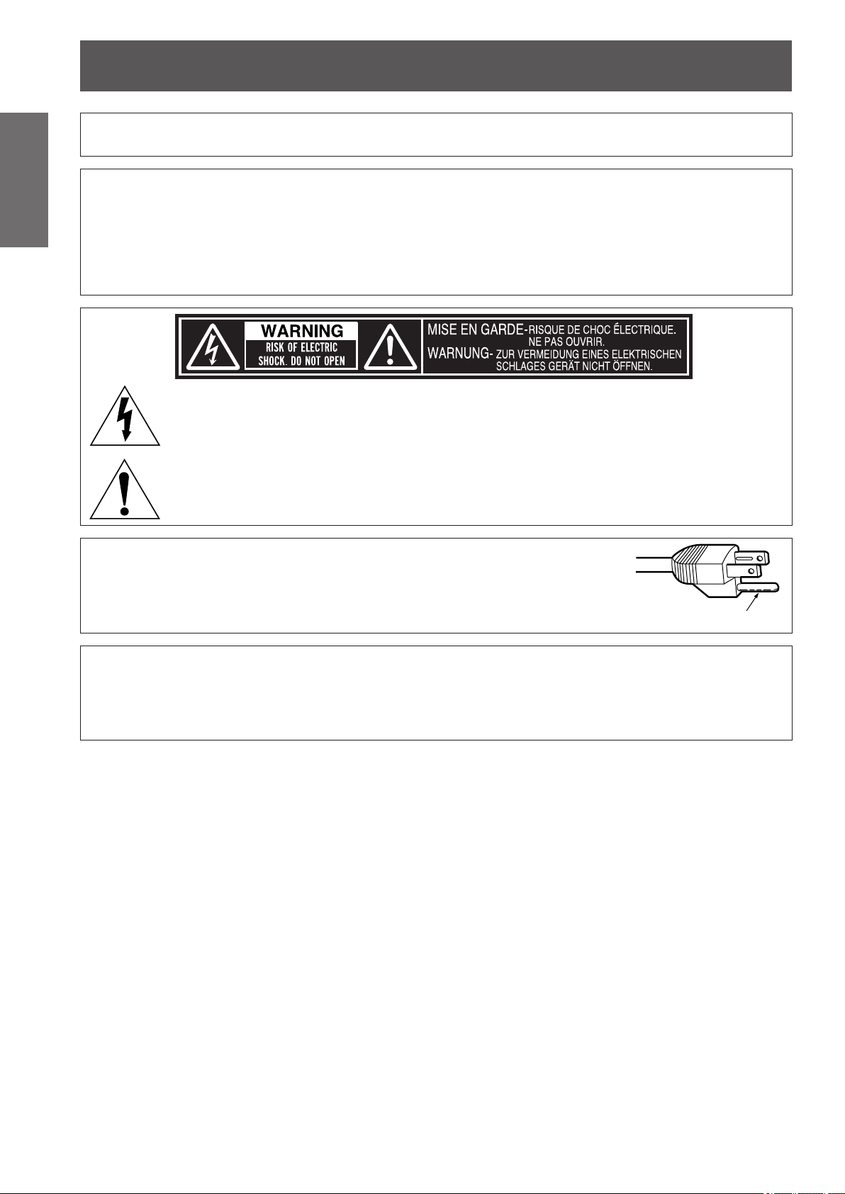
CAUTION: This equipment is equipped with a three-pin grounding-type power
plug. Do not remove the grounding pin on the power plug. This plug
will only t a grounding-type power outlet. This is a safety feature. If
you are unable to insert the plug into the outlet, contact an electrician.
Do not defeat the purpose of the grounding plug.
Do not remove
CAUTION: To assure continued compliance, follow the attached installation instructions, which includes
using the provided power cord and shielded interface cables when connecting to computer or
peripheral device. If you use serial port to connect PC for external control of projector, you must
use commercial RS-232C serial interface cable. Any unauthorized changes or modications to
this equipment will void the user’s authority to operate.

Read this rst!
ENGLISH
- 7
Important
Information
FCC NOTICE (USA)
Declaration of Conformity
Model Number: PT-AE8000U
Trade Name: Panasonic
Responsible Party: Panasonic Corporation of North America
Address: One Panasonic Way, Secaucus, NJ 07094
Telephone number: (877)803-8492
E-mail: [email protected]
This device complies with Part 15 of the FCC Rules.
Operation is subject to the following two conditions:
(1) This device may not cause harmful interference, and (2) this device must accept any interference received,
including interference that may cause undesired operation.
To assure continued compliance, follow the attached installation instructions and do not make any unauthorized
modications.
Caution:
This equipment has been tested and found to comply with the limits for a Class B digital device, pursuant
to Part 15 of the FCC Rules. These limits are designed to provide reasonable protection against harmful
interference in a residential installation. This equipment generates, uses and can radiate radio frequency
energy and, if not installed and used in accordance with the instructions, may cause harmful interference
to radio communications. However, there is no guarantee that interference will not occur in a particular
installation. If this equipment does cause harmful interference to radio or television reception, which can be
determined by turning the equipment off and on, the user is encouraged to try to correct the interference by
one or more of the following measures:
z
Reorient or relocate the receiving antenna.
z
Increase the separation between the equipment and receiver.
z
Connect the equipment into an outlet on a circuit different from that to which the receiver is connected.
z
Consult the dealer or an experienced radio/TV technician for help.
FCC Caution:
To assure continued compliance, follow the attached installation instructions and use only shielded interface
cables when connecting to computer and/or peripheral devices. Any changes or modications not expressly
approved by Panasonic Corp. of North America could void the user’s authority to operate this device.
NOTIFICATION (Canada)
This class B digital apparatus complies with Canadian ICES-003.
WARNING:
z
Not for use in a computer room as dened in the Standard for the Protection of Electronic Computer/Data
Processing Equipment, ANSI/NFPA 75.
z
For permanently connected equipment, a readily accessible disconnect device shall be incorporated in the
building installation wiring.
z
For pluggable equipment, the socket-outlet shall be installed near the equipment and shall be easily
accessible.
Notice (USA only):
z
This product has a High Intensity Discharge (HID) lamp that contains mercury. Disposal may be regulated
in your community due to environmental considerations. For disposal or recycling information, please visit
Panasonic website: http://www.panasonic.com/environmental or call 1-888-769-0149.

Read this rst!
8 -
ENGLISH
Important
Information
WARNING:
POWER
The wall outlet or the circuit breaker shall be installed near the equipment and shall be easily
accessible when problems occur. If the following problems occur, cut off the power supply
immediately.
Continued use of the projector in these conditions will result in re or electric shock.
z
If foreign objects or water get inside the projector, cut off the power supply.
z
If the projector is dropped or the cabinet is broken, cut off the power supply.
z
If you notice smoke, strange smells or noise coming from the projector, cut off the power supply.
Please contact an Authorized Service Center for repairs, and do not attempt to repair the projector yourself.
During a thunderstorm, do not touch the projector or the cable.
Electric shocks can result.
Do not do anything that might damage the power cord or the power plug.
If the power cord is used while damaged, electric shocks, short-circuits or re will result.
z
Do not damage the power cord, make any modications to it, place it near any hot objects, bend it
excessively, twist it, pull it, place heavy objects on top of it or wrap it into a bundle.
Ask an Authorized Service Center to carry out any repairs to the power cord that might be necessary.
Completely insert the power plug into the wall outlet and the power connector into the projector
terminal.
If the plug is not inserted correctly, electric shocks or overheating may occur and re will result.
z
Do not use plugs which are damaged or wall outlets which are coming loose from the wall.
Do not use anything other than the provided power cord.
Failure to observe this will result in electric shocks or re.
Clean the power plug regularly to prevent it from becoming covered in dust.
Failure to observe this will cause a re.
z
If dust builds up on the power plug, the resulting humidity can damage the insulation.
z
If not using the projector for an extended period of time, pull the power plug out from the wall outlet.
Pull the power plug out from the wall outlet and wipe it with a dry cloth regularly.
Do not handle the power plug and power connector with wet hands.
Failure to observe this will result in electric shocks.
Do not overload the wall outlet.
If the power supply is overloaded (ex., by using too many adapters), overheating may occur and re will result.

Read this rst!
ENGLISH
- 9
Important
Information
WARNING:
ON USE/INSTALLATION
Do not place the projector on soft materials such as carpets or sponge mats.
Doing so will cause the projector to overheat, which can cause burns, re or damage to the projector.
Do not set up the projector in humid or dusty places or in places where the projector may come into
contact with oily smoke or steam, ex. a bathroom.
Using the projector under such conditions will result in re, electric shocks or deterioration of components.
Deterioration of components (such as ceiling mount brackets) may cause the projector which is mounted on
the ceiling to fall down.
Do not install this projector in a place which is not strong enough to take the full weight of the
projector or on top of a surface which is sloped or unstable.
Failure to observe this will cause projector to fall down or tip over the projector, and severe injury or damage
could result.
Do not cover the air intake port or the air exhaust port.
Doing so will cause the projector to overheat, which can cause re or damage to the projector.
z
Do not place the projector in narrow, badly ventilated places such as closets or bookshelves.
z
Do not place the projector on cloth or papers, as these materials could be drawn into the air intake port.
Do not place your hands or other objects close to the air exhaust port.
Doing so will cause burns or damage your hands or other objects.
z
Heated air comes out of the air exhaust port. Do not place your hands or face, or objects which cannot
withstand heat close to this port.
Do not cover the air intake/exhaust ports or place anything within 100 mm (4") of them.
Doing so will cause the projector to overheat, which can cause re or damage to the projector.
Do not look and place your skin into the lights emitted from the lens while the projector is being used.
Doing so can cause burns or loss of sight.
z
Strong light is emitted from the projector’s lens. Do not look or place your hands directly into this light.
z
Be especially careful not to let young children look into the lens. In addition, turn off the main power when
you are away from the projector.
Never attempt to remodel or disassemble the projector.
High voltages can cause re or electric shocks.
z
For any inspection, adjustment and repair work, please contact an Authorized Service Center.
Do not project an image with the lens cover attached.
Doing so can cause re.
Do not allow metal objects, ammable objects, or liquids to enter inside of the projector. Do not allow
the projector to get wet.
Doing so may cause short circuits or overheating, and result in re, electric shock, or malfunction of the
projector.
z
Do not place containers of liquid or metal objects near the projector.
z
If liquid enters inside of the projector, consult your dealer.
z
Particular attention must be paid to children.
Use the ceiling mount bracket specied by Panasonic.
Defects in the ceiling mount bracket will result in falling accidents.
z
Attach the supplied safety cable to the ceiling mount bracket to prevent the projector from falling down.
Installation work (such as ceiling mount bracket) should only be carried out by a qualied technician.
If installation is not carried out and secured correctly it can cause injury or accidents, such as electric shocks.
z
Do not use anything other than an authorized ceiling mount bracket.
z
Be sure to use the provided accessory wire with an eye bolt as an extra safety measure to prevent the
projector from falling down. (Install in a different location to the ceiling mount bracket)

Read this rst!
10 -
ENGLISH
Important
Information
WARNING:
ACCESSORIES
Do not use or handle the batteries improperly, and refer to the following.
Failure to observe this will cause burns, batteries to leak, overheat, explode or catch re.
z
Do not use unspecied batteries.
z
Do not disassemble dry cell batteries.
z
Do not heat the batteries or place them into water or re.
z
Do not allow the + and - terminals of the batteries to come into contact with metallic objects such as
necklaces or hairpins.
z
Do not store batteries together with metallic objects.
z
Store the batteries in a plastic bag and keep them away from metallic objects.
z
Make sure the polarities (+ and -) are correct when inserting the batteries.
z
Do not use a new battery together with an old battery or mix different types of batteries.
z
Do not use batteries with the outer cover peeling away or removed.
If the battery uid leaks, do not touch it with bare hands, and take the following measures if necessary.
z
Battery uid on your skin or clothing could result in skin inammation or injury.
Rinse with clean water and seek medical advice immediately.
z
Battery uid coming in contact with your eyes could result in loss of sight.
In this case, do not rub your eyes. Rinse with clean water and seek medical advice immediately.
Do not disassemble the lamp unit.
If the lamp breaks, it could cause injury.
Lamp replacement
The lamp has high internal pressure. If improperly handled, an explosion and severe injury or accidents will
result.
z
The lamp can easily explode if struck against hard objects or dropped.
z
Before replacing the lamp, be sure to disconnect the power plug from the wall outlet.
Electric shocks or explosions can result if this is not done.
z
When replacing the lamp, turn the power off and allow the lamp to cool for at least one hour before
handling it otherwise it can cause burns.
Do not allow infants or pets to touch the remote control.
z
Keep the remote control out of the reach of infants and pets after using it.
Do not use the supplied power cord with devices other than this projector.
z
Using the supplied power cord with devices other than this projector may cause short circuits or
overheating, and result in electric shock or re.
Remove the depleted batteries from the remote control promptly.
z
Leaving them in the unit may result in uid leakage, overheating, or explosion of the batteries.

Read this rst!
ENGLISH
- 11
Important
Information
CAUTION:
POWER
When disconnecting the power cord, be sure to hold the power plug and power connector.
If the power cord itself is pulled, the lead will become damaged, and re, short-circuits or serious electric
shocks will result.
When not using the projector for an extended period of time, disconnect the power plug from the wall
outlet and remove the batteries from the remote control.
Failure to do so may result in re or electric shock.
Disconnect the power plug from the wall outlet before carrying out any cleaning and replacing the unit.
Failure to do so may result in electric shock.
ON USE/INSTALLATION
Do not place heavy objects on top of the projector.
Failure to observe this will cause the projector to become unbalanced and fall, which could result in damage or
injury. The projector will be damaged or deformed.
Do not put your weight on this projector.
You could fall or the projector could break, and injury will result.
z
Be especially careful not to let young children stand or sit on the projector.
Do not place the projector in extremely hot locations.
Doing so will cause the outer casing or internal components to deteriorate, or result in re.
z
Take particular care in locations exposed to direct sunlight or near stoves.
Always disconnect all cables before moving the projector.
Moving the projector with cables still attached can damage the cables, which will cause re or electric shocks
to occur.
ACCESSORIES
Do not use the old lamp unit.
If used it could cause lamp explosion.
If the lamp has broken, ventilate the room immediately. Do not touch or bring your face close to the
broken pieces.
Failure to observe this will cause the user to absorb the gas which was released when the lamp broke and
which contains nearly the same amount of mercury as uorescent lamps, and the broken pieces will cause
injury.
z
If you believe that you have absorbed the gas or that the gas has got into your eyes or mouth, seek
medical advice immediately.
z
Ask your dealer about replacing the lamp unit and check the inside of the projector.

Read this rst!
12 -
ENGLISH
Important
Information
CAUTION:
Viewing 3D video
Those with a medical history of oversensitivity to light, heart problems, or poor physical health should
not view 3D images.
This may lead to a worsening of medical conditions.
If you feel tiredness or discomfort, or other abnormality while viewing with 3D Eyewear, discontinue use.
Continuing use may cause health problems. Take a break as necessary.
When viewing 3D movies, aim to view one movie at a time and take a break as necessary.
When viewing 3D such as playing 3D games or using a PC where two way interaction is feasible, take
an appropriate break every 30 to 60 minutes.
Watching for long periods of time may cause eye fatigue.
Use 3D Eyewear when viewing 3D videos.
Do not tilt your head when viewing with 3D Eyewear.
Those who are near or far sighted, those with weaker eyesight in one eye, or those with astigmatism
should use corrective glasses etc. when using 3D Eyewear.
If the image appears distinctly double when viewing 3D video, halt usage.
Watching for long periods of time may cause eye fatigue.
View at a distance of at least three times the effective height of the screen.
Recommended distance: Screen size 2.03 m (80") (16:9): 3 m (9'10") or more
Screen size 2.54 m (100") (16:9): 3.8 m (12'6") or more
Viewing at distance closer than the recommended distance may cause eye fatigue. As with movies, if there are
black bands at the top and bottom of the video, view at a distance of 3 times or more of the height of the video
section.
Use of 3D Eyewear (optional)
Do not move about while wearing the 3D Eyewear.
This may cause the surroundings to darken and may lead to injuries suffered from falling over etc.
Do not use the 3D Eyewear other than for the indicated purpose.
Do not use 3D Eyewear that is broken.
This could lead to injury or eye fatigue.
Do not place objects that break easily close by when using 3D Eyewear.
3D video may be mistaken for actual objects, and the related bodily movements can cause damage to objects
and lead to injury.
Children younger than 5 or 6 years old should not use 3D Eyewear.
As it is difcult to guage the reactions of children to fatigue and discomfort their condition may worsen
suddenly.
If a child uses the 3D Eyewear, guardians should beware of the child’s eyes becoming tired.
If there are issues with the 3D Eyewear or it is broken, discontinue use immediately.
Continued use could lead to injury, eye fatigue, or health problems.
If you feel any strange skin sensations discontinue use of the 3D Eyewear.
Very occasionally there may be an allergy to the paint or material.
If the nose or temples turn red, or if pain or itching occur, discontinue use of the 3D Eyewear.
This may occur due to pressure through use over a long period and may lead to poor health.
Charge rechargeable 3D Eyewear by connecting it to the USB port of a Panasonic TV that supports 3D
video or a Panasonic-certied charger using the charging cable included with the 3D Eyewear.
Charging with any other device may result in battery leakage, heating, or rupture.
Read this rst!
ENGLISH
- 13
Important
Information
end of Read this rst
Brazil Only
Brasil Apenas
Manuseio de baterias usadas
BRASIL
Após o uso, as pilhas e /ou baterias poderão
ser entregues ao estabelecimento comercial
ou rede de assistência técnica autorizada.
Cobrir os terminais positivo (+) e negativo (-) com uma ta isolante adesiva, antes de depositar numa caixa
destinada para o recolhimento. O contato entre partes metálicas pode causar vazamentos, gerar calor, romper
a blindagem e produzir fogo.
Não desmonte, não remova o invólucro, nem amasse a bateria. O gás liberado pela bateria pode irritar a
garganta, danicar o lacre do invólucro ou o vazamento provocar calor, ruptura da blindagem e produzir fogo
devido ao curto circuito dos terminais.
Não incinere nem aqueça as baterias, elas não podem car expostas a temperaturas superiores a 100 °C
(212 °F). O gás liberado pela bateria pode irritar a garganta,
danicar o lacre do invólucro ou o vazamento provocar calor, ruptura da blindagem e produzir fogo devido ao
curto circuito dos terminais provocado internamente.
Evite o contato com o liquido que vazar das baterias. Caso isto ocorra, lave bem a parte afetada com bastante
água. Caso haja irritação, consulte um médico.
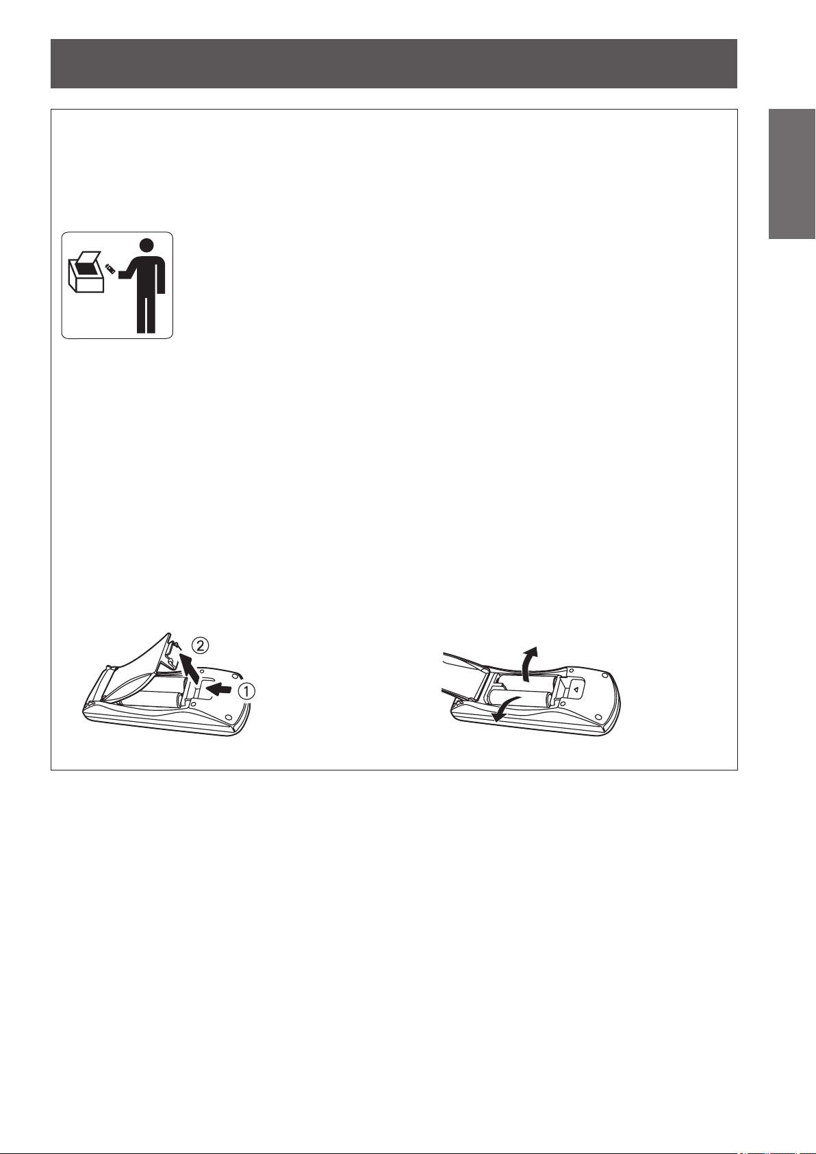
Remoção das baterias
1. Pressione a guia e levante a tampa.
2. Remova as baterias.

Precautions for use
14 -
ENGLISH
Important
Information
■
Be sure to use the projector after removing the packaging material, such as
the fastening tapes and protective sheet.
Take proper care when disposing of the removed packaging material.
Cautions when transporting
z
Ensure that the supplied lens cover is attached when transporting.
z
Hold the bottom of the projector when transporting.
z
Do not transport with the front adjustable feet extended. Doing so may result in damage to the front adjustable feet.
Cautions when installing
■
Do not set up the projector outdoors.
The projector is designed for indoor use only.
■
Do not use under the following conditions.
z
Places where vibration and impacts occur such as in a car or vehicle: Doing so may damage the internal parts
and result in malfunctions.
z
Near the exhaust of an air conditioner: Depending on the conditions of use, the screen may uctuate due to the hot
air from the air exhaust port or the heated or cooled air from the air conditioner. Take care so that the exhaust from
the projector or other equipment, or the air from the air conditioner does not blow toward the front of the projector.
z
Near lights (studio lamps, etc.) where temperature changes greatly (See “Operating environment”
page 106):
Doing so may shorten the life of the lamp or result in deformation of the outer case and malfunctions.
z
Near high-voltage power lines or near motors: Doing so may interfere with the operation of the projector.
■
About lens focus
The focus of high brightness projection lenses may not be stable immediately after turning power on due to the
effects of heat from light coming from light sources. Adjust lens focus 30 minutes after starting to project a video.
■
Make sure to set [HIGH ALTITUDE MODE] to [ON] when using the projector
at elevations of 1 400 m (4 593 ft) or higher and lower than 2 700 m (8 858 ft)
above sea level.
Failure to do so may shorten the life of the internal parts and result in malfunctions.
■
Make sure to set [HIGH ALTITUDE MODE] to [OFF] when using the projector
at elevations lower than 1 400 m (4 593 ft) above sea level.
Failure to do so may shorten the life of the internal parts and result in malfunctions.
■
Do not install the projector at elevations of 2 700 m (8 858 ft) or higher above
sea level.
Failure to do so may shorten the life of the internal parts and result in malfunctions.
■
Do not tilt the projector or place it on its side.
Do not tilt the projector body more than approximately ±30 ° vertically or ±10 °
horizontally. Overtilting may result in shortening the component’s lifespan.
■
Do not cover the air intake/exhaust ports or place anything within 100 mm (4")
of them.
■
Be sure to consult a specialized technician or your dealer when installing the
product on a ceiling.
An optional ceiling mount bracket is required.
Model No.: ET-PKA110H (for high ceilings), ET-PKA110S (for low ceilings)
+30°
-30°
Precautions for use
Precautions for use
ENGLISH
- 15
Important
Information
■
When using an infrared communications device
If you use infrared communication devices (such as infrared cordless headphones or an infrared wireless mic), communication
problems (such as noise) may occur. Therefore, use such devices in a location far away enough from the projector so as to have
no effect, or install the receiver of the device in a location that is not struck by light from the projector.
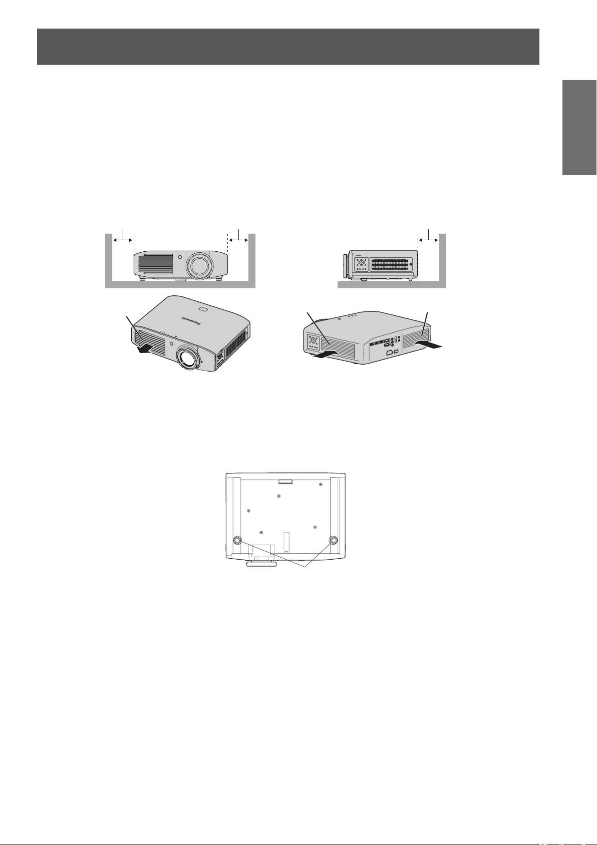
■
Installation precautions
z
Do not stack projectors.
z
Do not cover the projector’s air intake port or air exhaust port.
z
Install the projector so that cold air or hot air from air conditioners does not come in to direct contact with the air intake port
or air exhaust port.
100 mm (4") or more
Air intake port
Air intake port
Air exhaust port
100 mm (4") or more 100 mm (4") or more
z
Do not install the projector in an enclosed space.
If the projector needs to be installed in an enclosure, provide a separate air conditioning unit or ventilating equipment.
Emitted heat accumulates if ventilation is insufcient. This may cause the protection circuit of the projector to operate.
z
Use the front adjustable feet for oor installation only and for angle adjustment in such cases.
If you use the adjustable feet for any other purpose, the set may be damaged.
Adjustable feet

Precautions for use
16 -
ENGLISH
Important
Information
Cautions on use
■
In order to view clear video images
z
Clear, high contrast video can be viewed when curtains are closed and lights near the screen are extinguished in
order to stop light from reaching the screen.
z
In some rare cases, depending on the usage environment a “ickering” may appear on the screen due to the
effects of air from the exhaust port or hot/cold air from air conditioners. Do not set up this projector in a situation
where air from the exhaust of this device or other devices, or air from air conditioners is circulated to the front of
this device.
z
The focus of high brightness projection lenses may not be stable immediately after turning power on due to the
effects of heat from light coming from light sources. Focus stabilizes 30 minutes after video projection starts.
■
Do not touch the surface of the projection lens with bare hands.
If ngerprints or dirt are left on the projection lens, they will be enlarged and projected and will prevent the
viewing of clear video images. Also, always replace the lens cover when not using the projector.
■
About LCD panels
LCD panels are manufactured using high precision technologies, but in some cases they may have dead
pixels, or permanently lit pixels. Please understand that this is not a fault.
Also, projecting a still image for extended periods of time may lead to afterimages on LCD panels. Please be
aware that in some cases these afterimages may not disappear completely.
■
About optical components
If using in an environment with a high temperature, or where dust or tobacco smoke is present, the
replacement cycle of optical components such as LCD panels and polarizing plates may shorten even after
less than one year of use. For more details, please contact your dealer.
■
About the lamp
This product uses an internal high pressure mercury lamp for the light source.
High pressure mercury lamps have the following characteristics.
z
Brightness decreases with usage time.
z
In some cases, the lamp may make a large sound, crack, and reach the end of its lifespan as a result of shocks,
damage, and deterioration related to usage period.
z
Large disparities occur in lifespan due to individual properties and usage conditions. Lifespan is especially
affected if you use the lamp continuously for more than 6 hours or switch it ON/OFF rapidly.
z
Very occasionally the lamp may crack after starting projection.
z
The possibility of cracking increases as the lamp nears the end of its lifespan.
z
If the lamp cracks, gas may be leaked from inside and smoke may be seen.
z
Please prepare a spare lamp in advance.
About disposal
To dispose of the product, inquire your local authorities or dealer for correct methods of disposal.
The lamp contains mercury. When disposing of used lamp units, contact your local authorities or dealer for correct
methods of disposal.
Precautions for use
ENGLISH
- 17
Important
Information
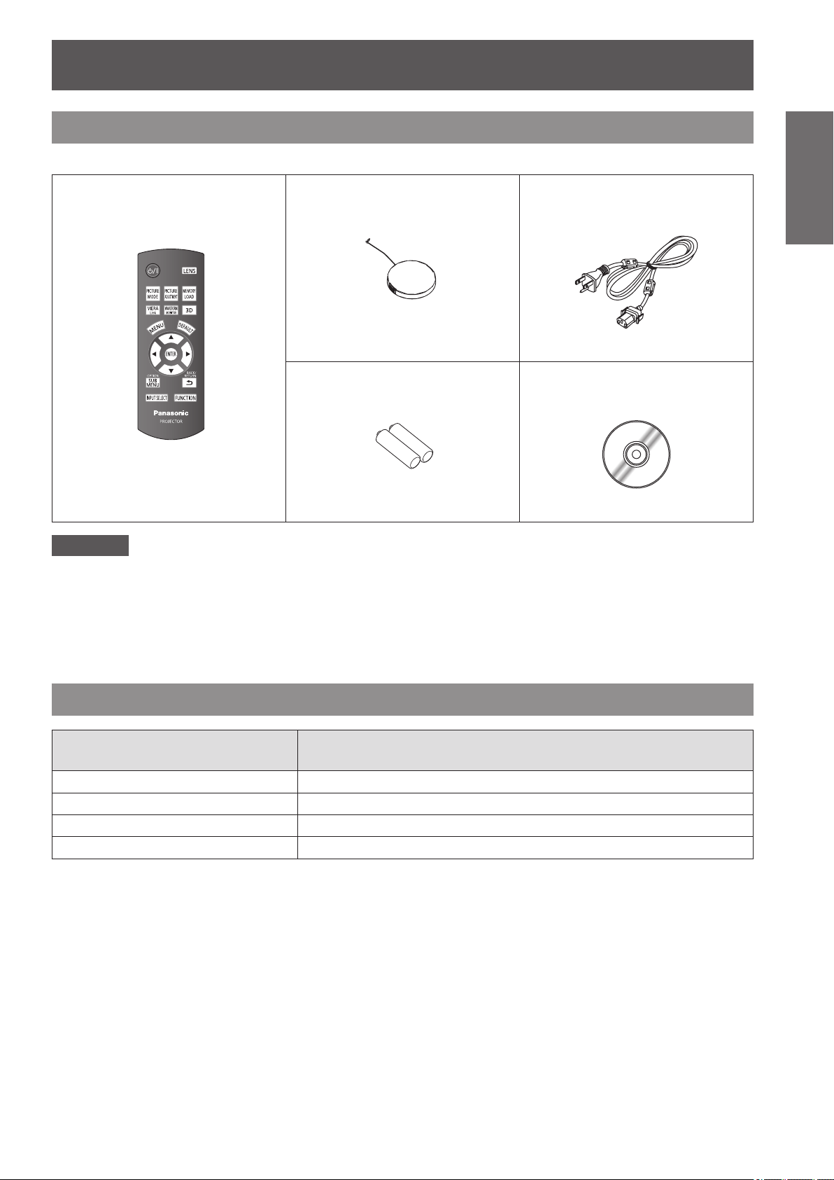
Accessories
Please conrm that the items displayed below are included.
Wireless remote control unit: 1
(N2QAYB000680)
Lens cover: 1
(TXFKK01THHZ)
(Attached to the projector by
default.)
Power cord: 1
(TXFSX01RWDZ)
AA/R6 battery: 2
(For remote control unit)
CD-ROM: 1
(TXFQB02THHZ)
Attention
z
Dispose of the packaging appropriately after removing from the product.
z
Contact an Authorized Service Center if you lose any of the included items.
z
The model number of accessories and optional accessories may be changed without prior notication.
z
Store small parts out of reach of infants.
z
Store the lens cover properly.
The lens cover protects the projection lens from dust and dirt.
Attach the lens cover when not using the device.
Optional accessories
Optional accessories
(product names)
Model No.
Ceiling mount bracket ET-PKA110H (for high ceilings), ET-PKA110S (for low ceilings)
3D IR Transmitter ET-TRM110
Replacement lamp unit ET-LAA410
3D Eyewear TY-EW3D3MU
*1*2
*1: If you do not have a Panasonic 3D TV, use a charger that has a USB2.0 port for charging your Eyewear. The
recommended charger is Apple USB Power Adapter for iPhone.
*2: The code at the end of the model number of 3D Eyewear may differ depending on the country of purchase.
About your projector
18 -
ENGLISH
Preparation
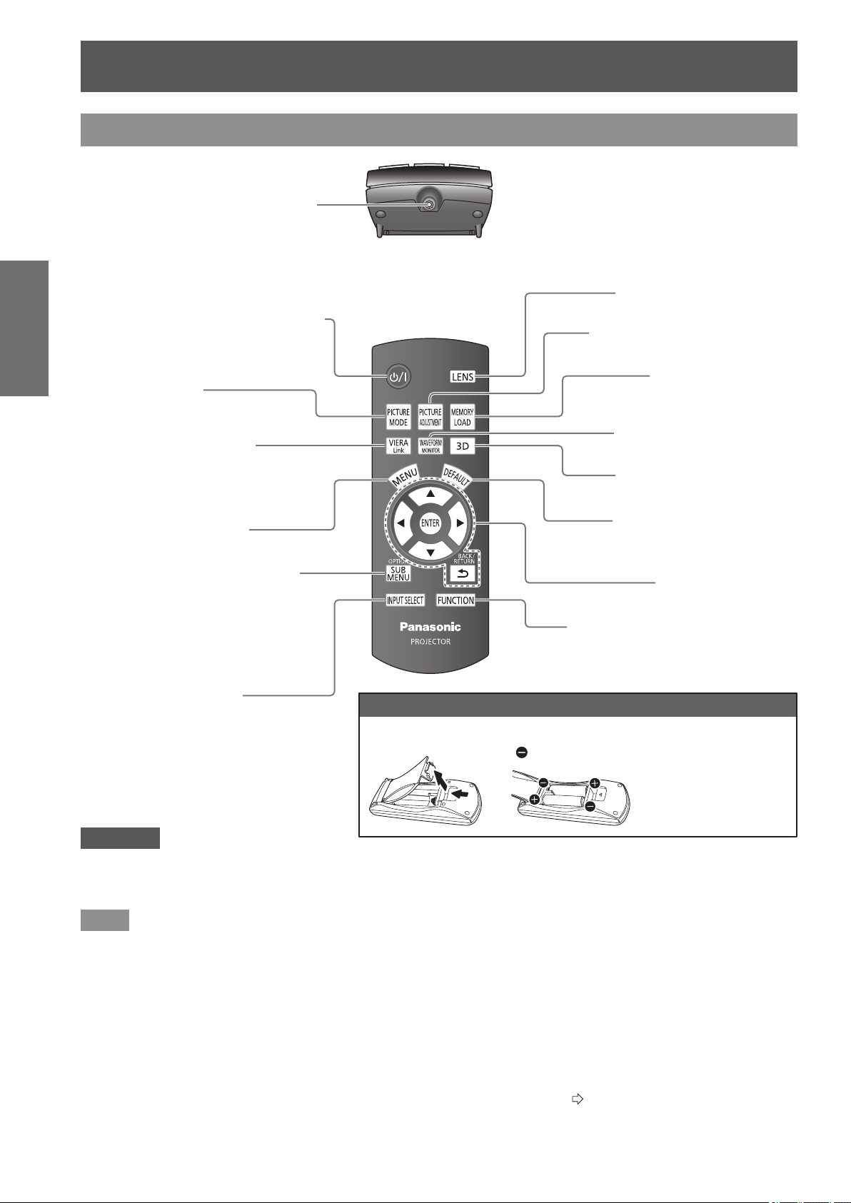
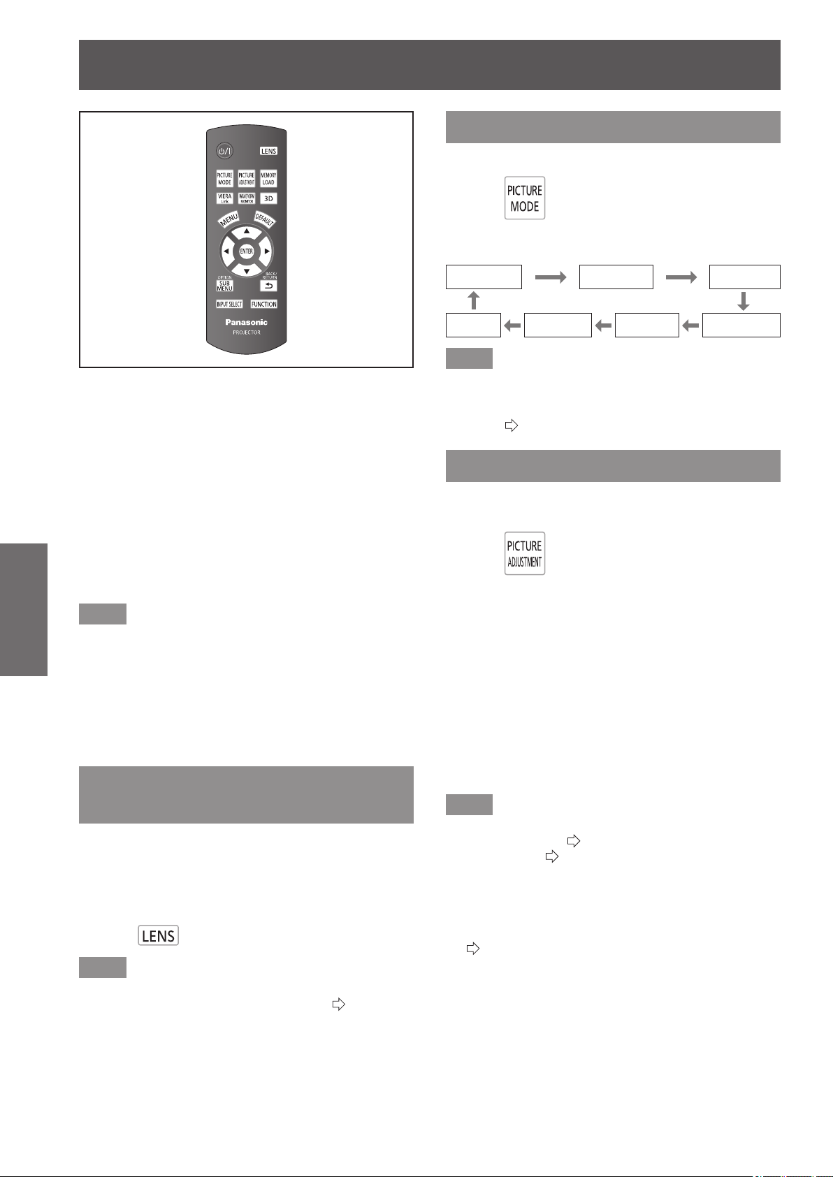
Remote control
■
Top
■
Front
Adjust the zoom and focus.
Display the [MEMORY
LOAD] menu.
Display the input waveform.
Reset adjusted menu values
to the default settings.
Use for menu screen
operation.
Display the [3D SETTINGS]
menu.
Allocate frequently used operations
and use as a shortcut button.
Inserting and removing the remote control batteries
Open the cover.
Insert the batteries and
replace the cover (insert
from
side).
Display the menu screen.
Switch the input signals.
Cycle through the
[PICTURE MODE].
Display the [VIERA LINK]
menu.
Remote control signal transmitter
Send remote control signal.
Point at the remote control receiver part on the
projector when using.
Attention
z
Do not drop the remote control.
z
Avoid contact with liquids or moisture.
z
Do not attempt to disassemble or modify the remote control.
Note
z
Pressing buttons on the remote control when button lights is set to on illuminates the button lights.
Button lights dim if no actions are carried out after approximately 5 seconds, and then extinguish if no actions are carried
out after a further 5 seconds.
z
When pointed directly at the receiver on the front of the projector, the remote control can be used up to a distance of
approximately 7 m (23'). It may also be used at a vertical/horizontal angle of up to ±30 degrees.
z
The remote control may not operate correctly if there is an obstacle between it and the receiver on the projector.
Signals from the remote control can be reected off a screen when using the projector, but limitations to the range of
operability may occur due to reected light loss resulting from the properties of the screen.
z
The remote control may not be usable if the receiver is exposed to uorescent or other strong lights. As far as is possible,
keep the remote control away from light sources.
z
When viewing 3D images the remote control may not respond well in some cases. (
page 70)
● Follow the reverse
procedure to remove the
batteries.
About your projector
Display menus of external devices
when using VIERA Link.
Change the operation mode during
gamma adjustment.
Change the detection level of parallax
when the parallax adjustment monitor
is displayed (when [Mode3] is set).
With the <MAIN POWER> switch of the
projector turned <ON>, switch between
the standby mode and projection mode.
Display the [PICTURE] menu or
[ADVANCED MENU] menu.
About your projector
ENGLISH
- 19
Preparation
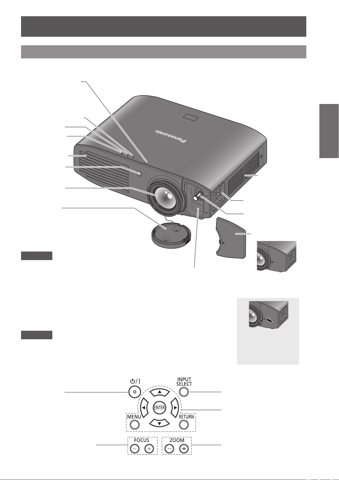
Projector body
Attention
z
Ensure that there are no build ups of dirt on the air intake and exhaust ports.
z
Do not place objects in front of the transmitter for the 3D Eyewear.
This may lead to the 3D Eyewear not operating correctly.
Use for menu screen
operation
Switch input
Adjust the focus Adjust the size of the
image
■
Control panel
Power button
With the <MAIN POWER>
switch of the projector turned
<ON>, switch between the
standby mode and projection
mode.
Temperature indicator
Lamp indicator
Power indicator
Control panel
Lens shift cover
Lens shift lever
Lens cover
Protects the projection lens from dust and dirt.
Attach the lens cover when
not using the device
.
When the lens shift
cover is closed
Opening the lens shift
cover
Press the cover and
slide.
Air exhaust port
Remote control
signal receiver
Projection lens
■
Top and front view
3D Eyewear transmitter
Transmits a signal for
3D Eyewear (optional
accessory) while viewing
3D video. (May appear as
a red dot when seen in a
dark area.)
Attention
z
Do not place your hands or objects close to the exhaust port.
- Do not place hands or face near.
- Do not place near objects that are intolerant to heat.
- Inserting ngers may result in injury.
Hot air is expelled from the exhaust port and can cause burns,
injuries, and deformation
.
Color sensor window
However, this projector
is not equipped with a
color sensor.
Air intake port /
Air lter cover
About your projector
20 -
ENGLISH
Preparation
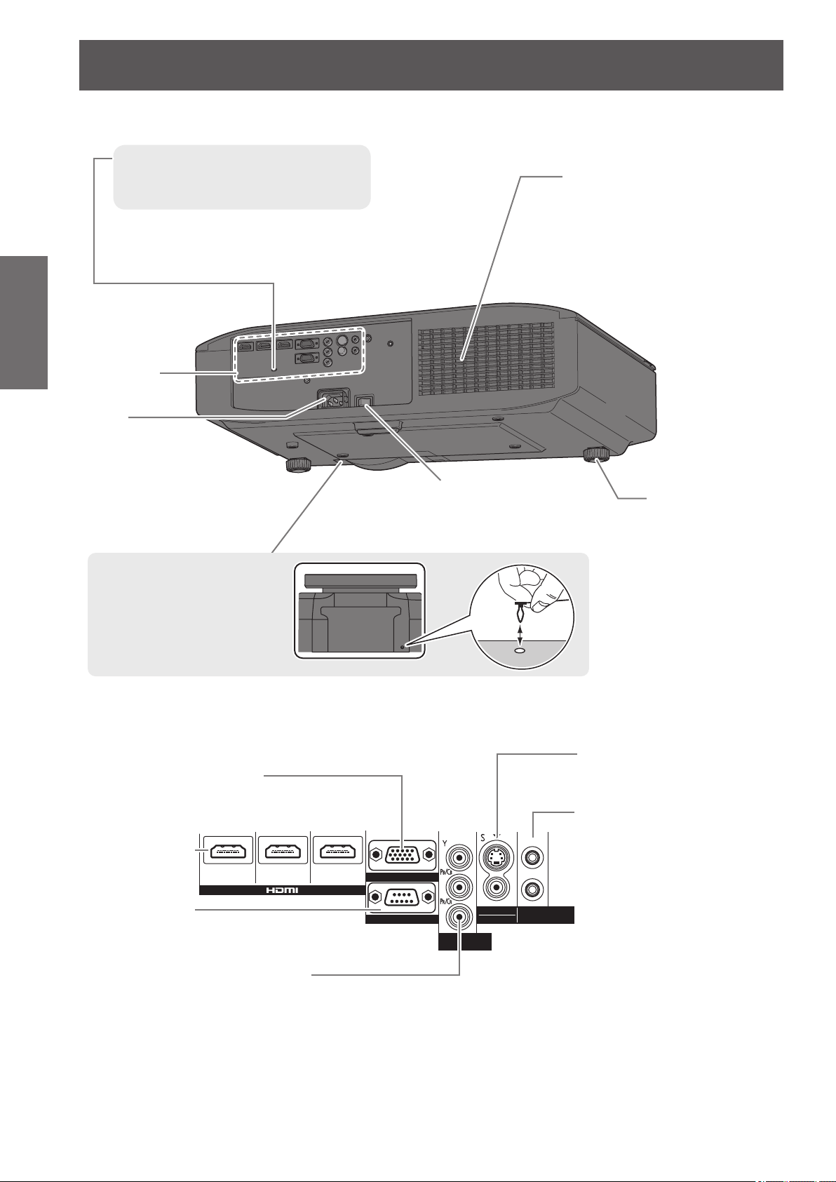
Main power
Switch the projector on/off.
Lens cover attachment
hole
Connecting
terminals
Air intake port
■
Back and bottom view
Security slot
The security slot is compatible with the
Kensington MicroSaver Security System.
Front adjustable
feet
Screw up/down to
adjust the projection
angle.
AC IN
Connect the
power cord
included.
■
Connecting terminals
SERIAL
Terminal for controlling the
projector using a computer.
HDMI IN
Connect HDMI
signal cables.
COMPUTER IN
Terminal for RGB signal or YC
B
C
R
/
YP
B
P
R
signal input from a computer.
COMPONENT IN
Connect a color component
signal cable. (YC
B
C
R
/YP
B
P
R
)
ヤヰヮヱヶヵユンチチリワ
ヴユンリモロ
ヴ
ノ
ヷリュユヰチリワ
ヵンリヨヨユンチバ
ピュチヴラヶヵヵユンチヰヶヵ
リワチヒリワチビリワチピ
ヒ
ビ
ヤヰヮヱヰワユワヵ
リワ
ヷリュユヰチリワ
TRIGGER /
3D SHUTTER OUT
Dual-purpose trigger terminal for
connecting and controlling the
projector and external devices,
as well as for connecting the
3D IR Transmitter (optional
accessory) and controlling 3D
Eyewear.
S-VIDEO IN/VIDEO IN
Terminal for inputting
S-VIDEO/VIDEO signal.
Setting up
ENGLISH
- 21
Getting Started
Setting up
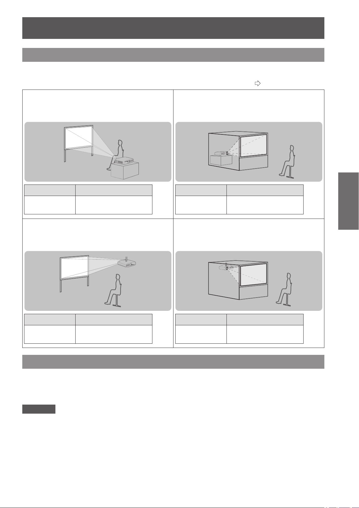
Projection method
You can use any of the following 4 projection methods. Select a projection method suitable for the position of the
projector.
For projection method settings, see [PROJECTION METHOD] in the [OPTION] menu. (
page 78)
■
Setting on a desk/oor and projecting
from front
Menu Method
[PROJECTION
METHOD]
[FRONT/DESK]
■
Setting on a desk/oor and
projecting from rear
(using a translucent screen)
Menu Method
[PROJECTION
METHOD]
[REAR/DESK]
■
Mounting on the ceiling and projecting
from front
Menu Method
[PROJECTION
METHOD]
[FRONT/CEILING]
■
Mounting on the ceiling and
projecting from rear
(with a translucent screen)
Menu Method
[PROJECTION
METHOD]
[REAR/CEILING]
Parts for ceiling mount (optional)
You can install the projector on the ceiling using the optional ceiling mount bracket (model no.: ET-PKA110H (for
high ceilings) and ET-PKA110S (for low ceilings)).
z
Use only the ceiling mount brackets specied for this projector.
z
Refer to the installation manual for the ceiling mount bracket when you install the bracket and the projector.
Attention
To ensure projector performance and security, installation of the ceiling mount bracket must be carried by your
dealer or a qualied technician.
Setting up
22 -
ENGLISH
Getting Started
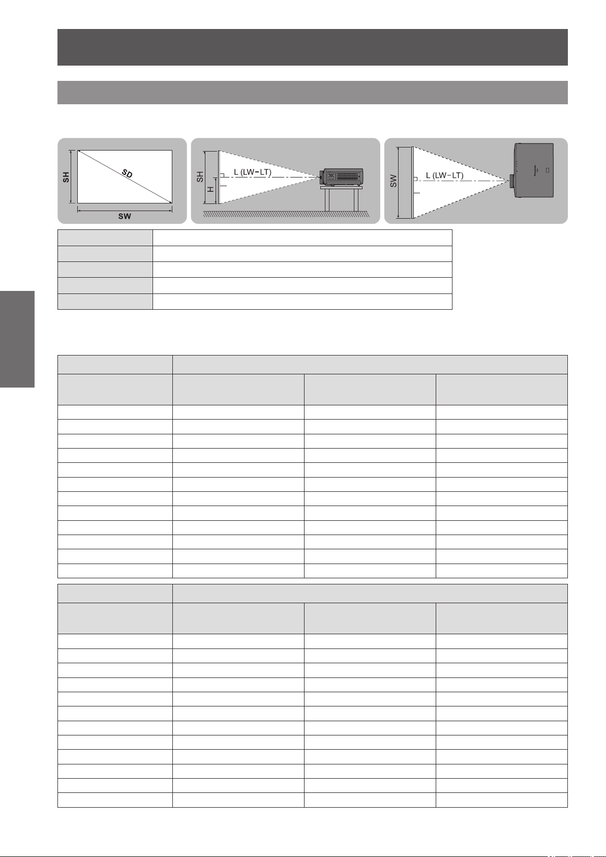
Projection related
Install the projector with reference to the gure below and the projection distance. You can adjust the display size
and display position according to the screen size and screen position.
Projection screen
Screen
Screen
L (LW - LT)
*
1
Projection distance (m)
SH Screen height (m)
SW Screen width (m)
H Distance from the center of the lens to the image lower end (m)
SD Screen diagonal size (m)
*1 LW: Minimum projection distance
LT: Maximum projection distance
(All measurements below are approximate and may differ slightly from the actual measurements.)
Projection screen size 16:9 size
Screen Diagonal (SD)
Minimum distance
(LW)
Maximum distance
(LT)
Height position
(H)
1.02 m (40") 1.16 m (3' 10") 2.37 m (7' 9") -0.25 to 0.75 m
1.27 m (50") 1.47 m (4' 10") 2.98 m (9' 9") -0.31 to 0.93 m
1.52 m (60") 1.77 m (5' 10") 3.58 m (11' 9") -0.38 to 1.13 m
1.78 m (70") 2.07 m (6' 9") 4.18 m (13' 9") -0.44 to 1.31 m
2.03 m (80") 2.37 m (7' 9") 4.79 m (15' 9") -0.50 to 1.50 m
2.29 m (90") 2.67 m (8' 9") 5.39 m (17' 8") -0.56 to 1.68 m
2.54 m (100") 2.98 m (9' 9") 6.00 m (19' 8") -0.63 to 1.88 m
3.05 m (120") 3.58 m (11' 9") 7.20 m (23' 7") -0.75 to 2.24 m
3.81 m (150") 4.49 m (14' 9") 9.02 m (29' 7") -0.94 to 2.81 m
5.08 m (200") 6.00 m (19' 8") 12.04 m (39' 6") -1.25 to 3.74 m
6.35 m (250")
*1
7.51 m (24' 8") 15.06 m (49' 5") -1.56 to 4.67 m
7.62 m (300")
*1
9.02 m (29' 7") 18.08 m (59' 4") -1.87 to 5.61 m
Projection screen size 2.35:1 size
Screen Diagonal (SD)
Minimum distance
(LW)
Maximum distance
(LT)
Height position
(H)
1.02 m (40") 1.23 m (4' 0") 2.51 m (8' 3") -0.30 to 0.70 m
1.27 m (50") 1.55 m (5' 1") 3.15 m (10' 4") -0.37 to 0.87 m
1.52 m (60") 1.87 m (6' 2") 3.78 m (12' 5") -0.45 to 1.05 m
1.78 m (70") 2.19 m (7' 2") 4.42 m (14' 6") -0.52 to 1.22 m
2.03 m (80") 2.51 m (8' 3") 5.06 m (16' 7") -0.60 to 1.40 m
2.29 m (90") 2.83 m (9' 3") 5.70 m (18' 8") -0.67 to 1.57 m
2.54 m (100") 3.15 m (10' 4") 6.34 m (20' 10") -0.76 to 1.75 m
3.05 m (120") 3.78 m (12' 5") 7.61 m (25' 0") -0.90 to 2.09 m
3.81 m (150") 4.74 m (15' 7") 9.53 m (31' 3") -1.13 to 2.62 m
5.08 m (200") 6.34 m (20' 10") 12.72 m (41' 9") -1.50 to 3.49 m
6.35 m (250")
*1
7.93 m (26' 0") 15.91 m (52' 2") -1.87 to 4.36 m
7.62 m (300")
*1
9.53 m (31' 3") 19.10 m (62' 8") -2.25 to 5.23 m
Setting up
ENGLISH
- 23
Getting Started
Projection screen size
16:9 in 2.35:1 size
*2
Screen Diagonal (SD)
Minimum distance
(LW)
Maximum distance
(LT)
Height position
(H)
1.27 m (50") 1.16 m (3' 10") 2.37 m (7' 9") -0.25 to 0.75 m
1.52 m (60") 1.40 m (4' 7") 2.85 m (9' 4") -0.30 to 0.90 m
1.78 m (70") 1.64 m (5' 5") 3.33 m (10' 11") -0.35 to 1.05 m
2.03 m (80") 1.88 m (6' 2") 3.82 m (12' 6") -0.40 to 1.20 m
2.29 m (90") 2.13 m (7' 0") 4.30 m (14' 1") -0.45 to 1.35 m
2.54 m (100") 2.37 m (7' 9") 4.78 m (15' 8") -0.50 to 1.49 m
3.05 m (120") 2.85 m (9' 4") 5.74 m (18' 10") -0.60 to 1.79 m
3.81 m (150") 3.57 m (11' 9") 7.19 m (23' 7") -0.75 to 2.24 m
5.08 m (200") 4.78 m (15' 8") 9.60 m (31' 6") -0.99 to 2.98 m
6.35 m (250")
*1
5.98 m (19' 7") 12.02 m (39' 5") -1.24 to 3.73 m
7.62 m (300")
*1
7.19 m (23' 7") 14.43 m (47' 4") -1.49 to 4.47 m
*1: The maximum size of the projection screen for 3D display is 5.08 m (200").
*2: Use when switching between 2.35:1 and 16:9 aspect images and viewing on a 2.35:1 size screen.
You can calculate projection dimensions other than those in the above table from the projection screen size SD (m)
using the formula below.
All units are meters. (Values obtained using the formula below contain a slight error.)
If the projection screen size is assumed to be SD,
16:9 size 2.35:1 size
Projection screen height (SH) = SD (m) × 0.490 = SD (m) × 0.392
Projection screen width (SW) = SD (m) × 0.872 = SD (m) × 0.920
Minimum distance (LW) = SD (m) × 1.189 − 0.04 = SD (m) × 1.256 − 0.04
Maximum distance (LT) = SD (m) × 2.378 − 0.05 = SD (m) × 2.512 − 0.05
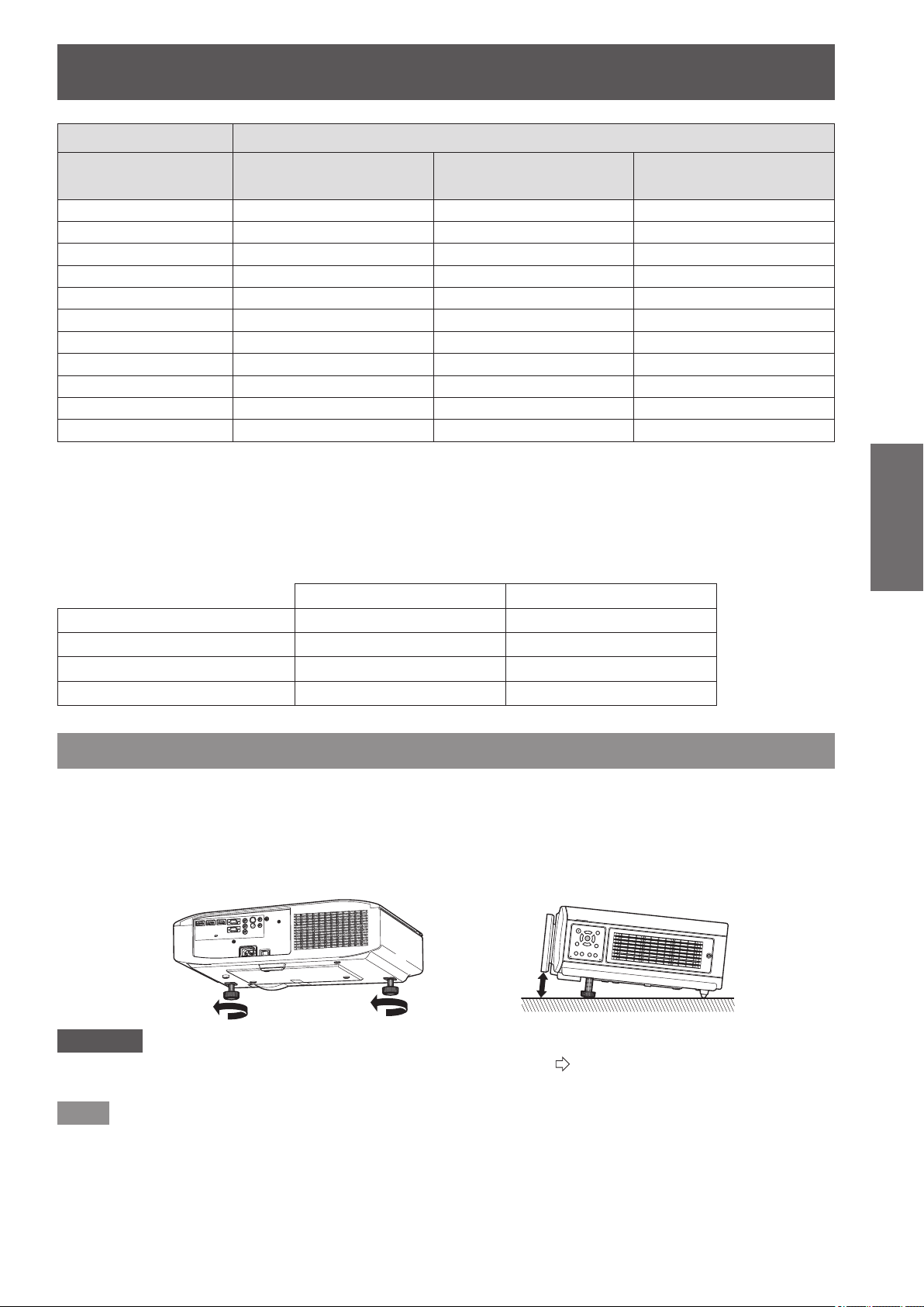
Front adjustable feet and throwing angle
Install the projector on a at surface with its front side become parallel to the screen surface so that the screen
becomes rectangle.
If the screen is tilted towards the bottom, extend the adjustable feet to make a rectangle screen. If the projector is
tilted horizontally, use the adjustable feet to level the projector.
As shown in the diagram, the feet can be extended by turning the front adjustable feet, and can be retracted by
turning in the opposite direction.
Attention
z
Hot air is expelled from the air exhaust port. Do not touch the air exhaust port (
page 19) directly when you adjust the front
leg adjustable feet.
Note
z
Tighten the front adjustable feet until you hear them click into place.
Setting up
24 -
ENGLISH
Getting Started
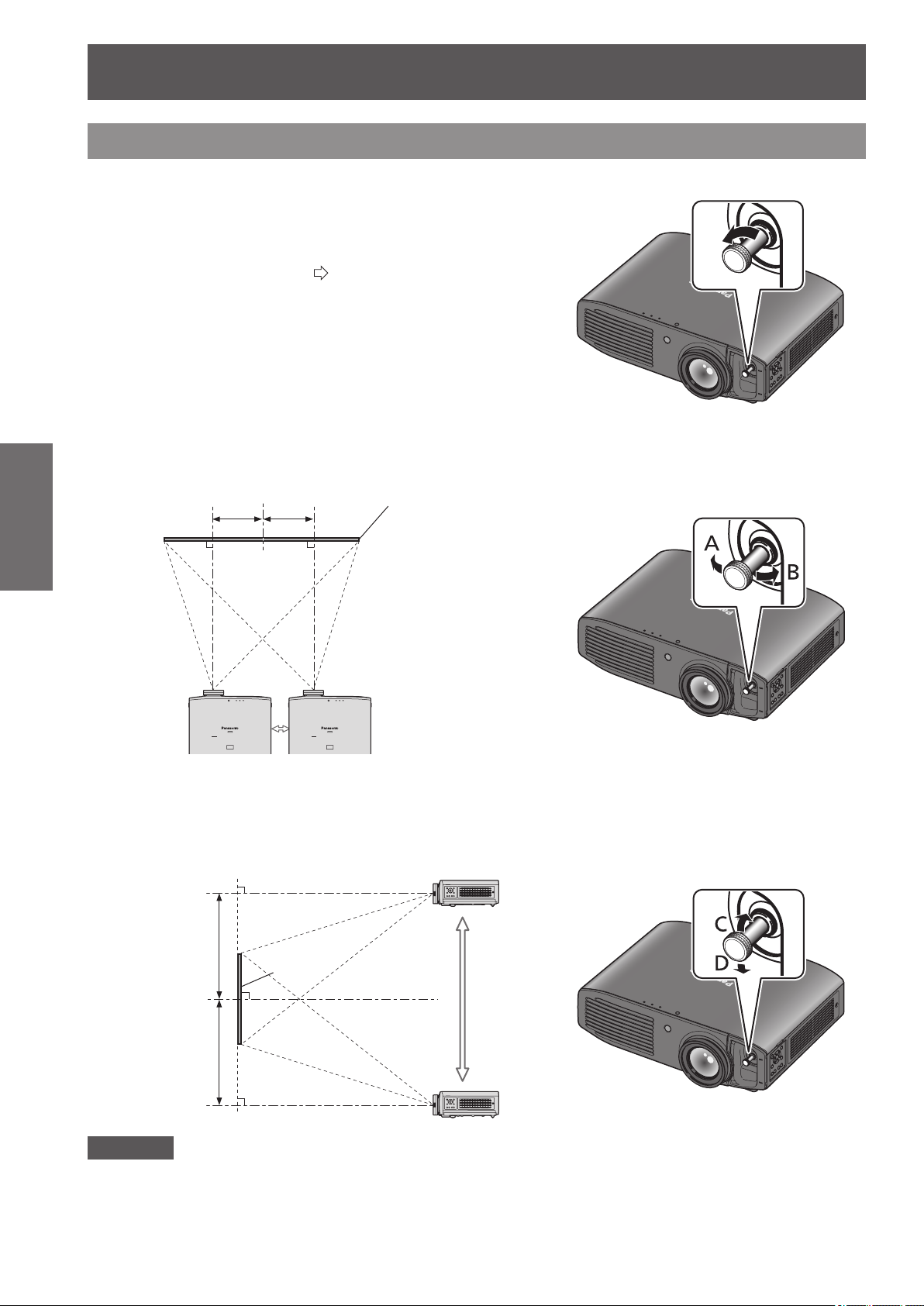
Lens shift and positioning
If the projector is not positioned right in front of the center of the screen, you can adjust the projected image
position by moving the lens shift dials within the shift range of the lens.
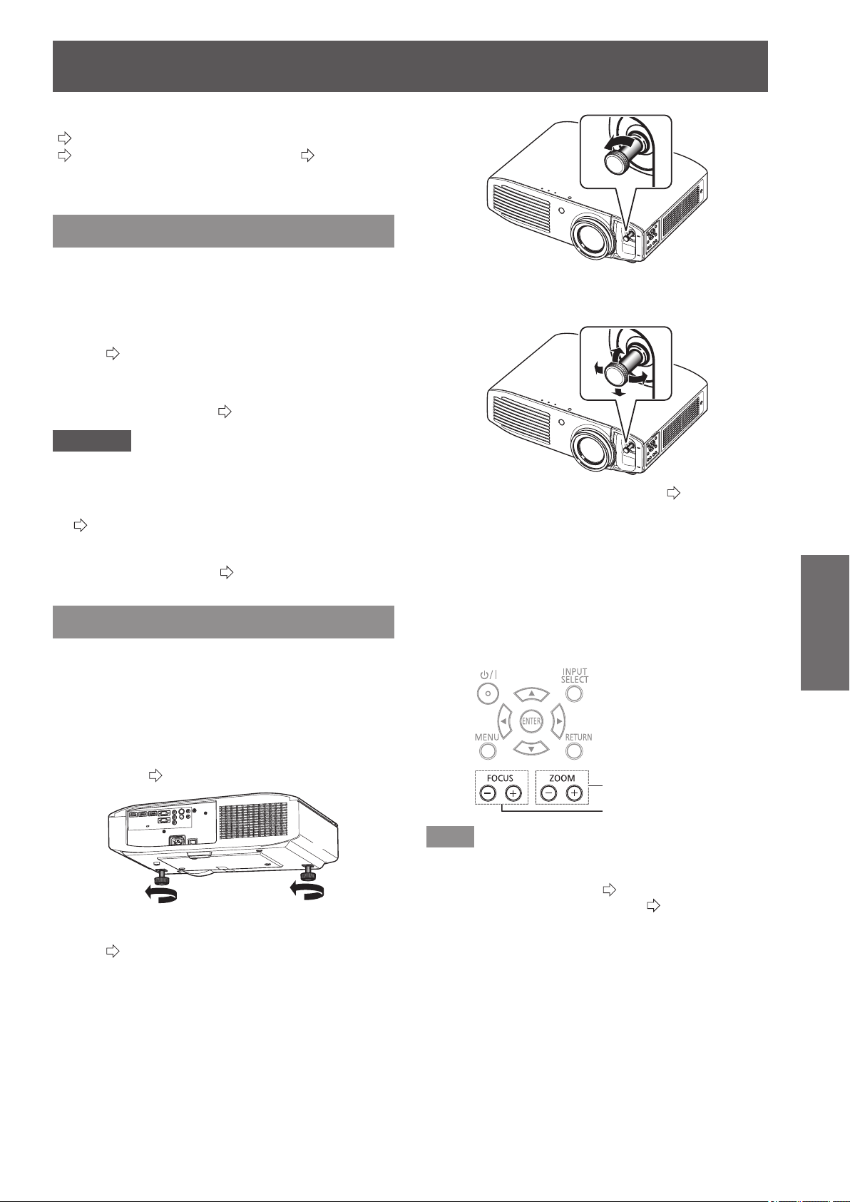
■
Adjusting the lens shift
1) Remove the lens shift cover.
z
See “About your projector” (
page 19) regarding how to
open the lens shift cover.
2) Rotate the lens shift lever in the direction shown
in the gure (counterclockwise) to release the lock.
3) Adjust projection using the lens shift lever.
●
Horizontal shift
Adjust the projection by moving the lens shift lever horizontally according to the installation position of the
screen and projector.
Up to approximately
26% of the
projection screen
Up to approximately
26% of the
projection screen
Move the lens shift
lever in direction A
Screen
Move the lens shift
lever in direction B
●
Vertical shift
Adjust by moving the lens shift lever vertically according to the installation position of the screen and
projector.
Up to
approximately
100% of the
projection
screen
Up to
approximately
100% of the
projection
screen
Move the lens shift
lever in direction D
Move the lens shift
lever in direction C
Screen
Attention
z
Do not force the lens shift lever. If excessive force is placed on the lever, it may break.
4) Rotate the lens shift lever clockwise to x.
5) Attach the lens shift cover.
Setting up
ENGLISH
- 25
Getting Started
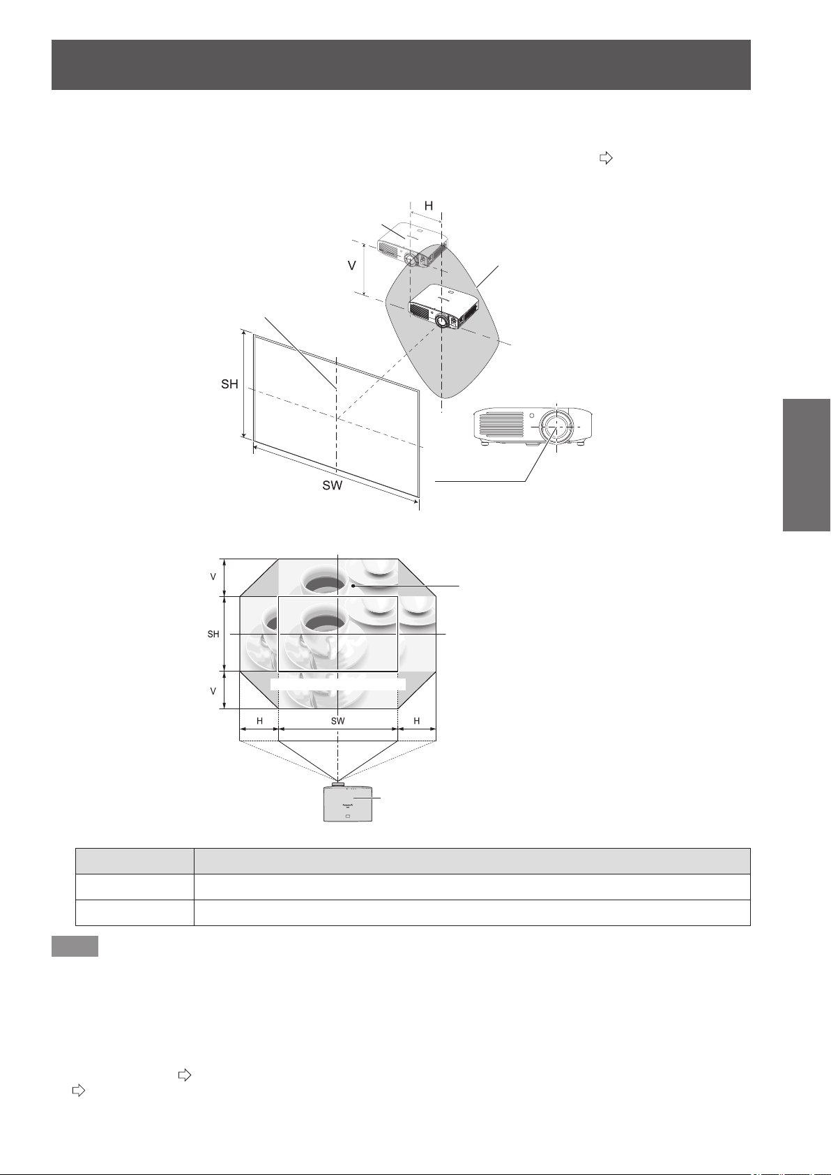
■
Projector location range
The setting position can be adjusted within the following range.
See “Projection related” regarding adjustment of the projection screen height (SH) and width (SW). (
page 22)
●
Projector setting range when the screen position is xed
Projector
Vertical center of screen
Center of lens
Screen
Projector setting range
(center of lens)
●
Shift range of the projection screen when the projector position is xed
Projector
Projection position with no lens shift
Shift range for
projection screen
Shift direction Maximum range of adjustment
Horizontal (H) Approximately 26% of the projection screen width (SW)
Vertical (V) Approximately 100% of the projection screen height (SH)
Note
z
Position the projector directly in front of the screen and move the lens shift lever to the center to obtain the optimum
projection image quality.
z
When the lens shift lever is at the horizontal limit of the shift range, you cannot move the lever to the vertical limit. Likewise,
when the lens shift lever is at the vertical limit of the shift range, you cannot move the lever to the horizontal limit.
z
Shift the lens position within the adjustment range. If you shift the lens position outside the adjustment range, a restriction is
imposed on the lens movement to protect the optical components and the focus changes.
z
If the projected image cannot be t into the screen using the lens shift function alone, adjust the projection angle using
the adjustable feet (
page 23), and then correct the keystone distortion using the [KEYSTONE] in the [POSITION] menu.
(
page 63)
Connections
26 -
ENGLISH
Getting Started
Connections
Before connecting to the projector
z
Read and follow the operating and connecting instructions of each peripheral device.
z
The peripheral devices must be turned off.
z
If not provided or sold separately with each peripheral device, obtain the connection cables required for system connection
in accordance with the device to be connected.
z
If the video signal from the video source contains a lot of jitter, the image may appear to be wobble. In such cases, a time
base corrector (TBC) must be connected.
z
The signals that can be connected to the projector include VIDEO, S-VIDEO, analog-RGB (with TTL sync. level) and digital
signal.
z
Some computer models are not compatible with the projector.
z
See “List of compatible signals” for the types of video signals that can be used with this projector. (
page 100)
z
Audio cables must be connected from each external device directly to the audio reproduction system.
Caution
When connecting to a computer or other equipment, use the power cord included with each device and a
sealed, commercially available cable.
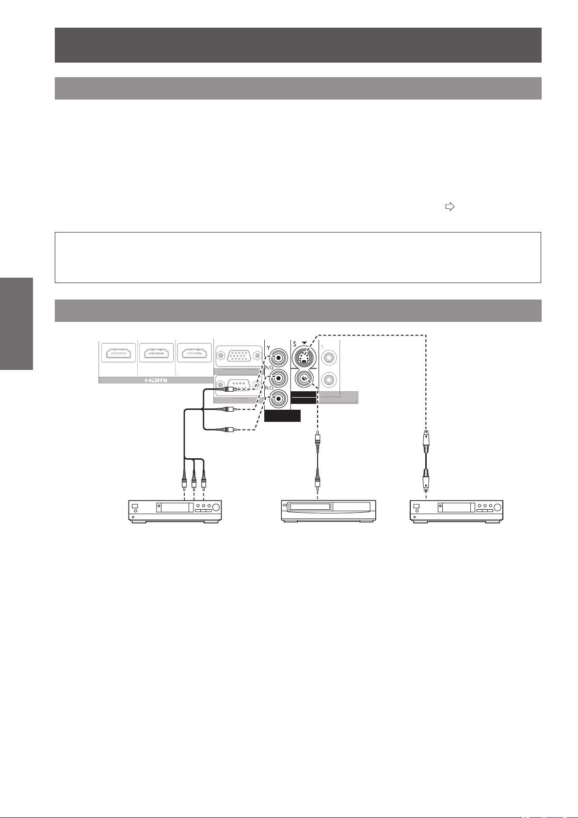
Connecting example: COMPONENT IN/S-VIDEO IN/VIDEO IN
ヤヰヮヱヶヵユンチチリワ
ヴユンリモロ
ヴ
ノ
ヷリュユヰチリワ
ヵンリヨヨユンチバ
ピュチヴラヶヵヵユンチヰヶヵ
リワチヒリワチビリワチピ
ヒ
ビ
ヤヰヮヱヰワユワヵ
リワ
ヷリュユヰチリワ
ヤ
ヰ
ヮヱ
ヶ
ヵユンチチリ
ワ
ヴ
ユンリモ
ロ
リワ
チ
ヒ
リワ
チ
ビ
リ
ワチピ
ヵンリヨヨユンチバ
バ
ピュチ
ヴ
ラ
ヶ
ヵヵユンチ
ヰヶ
ヵ
ヒ
ビ
DVD player Video player DVD player
To VIDEO
output
To S-VIDEO
output
To COMPONENT
video output
Connections
ENGLISH
- 27
Getting Started
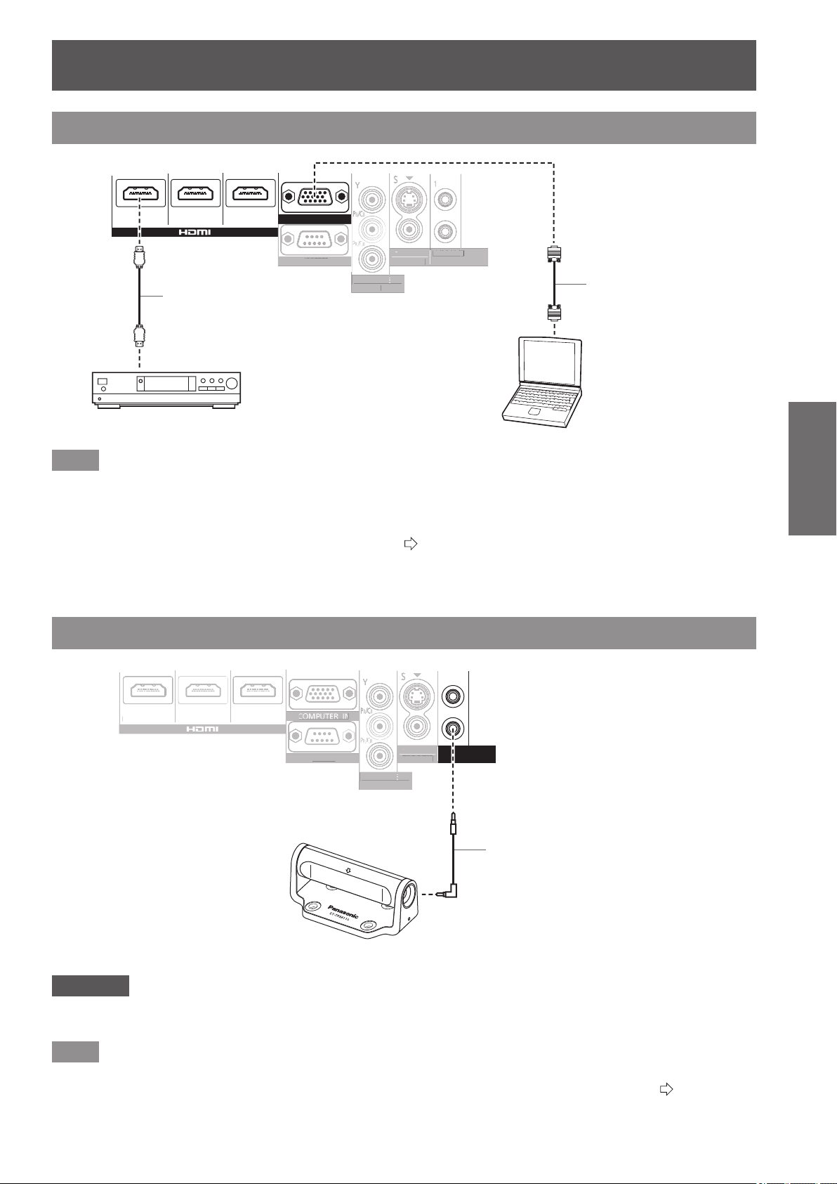
Connecting example: HDMI IN/COMPUTER IN
ヤヰヮヱヶヵユンチチリワ
ヴユンリモロ
ヴ
ノ
ヷリュユヰチリワ
ヵンリヨヨユンチバ
ピュチヴラヶヵヵユンチヰヶヵ
リワチヒリワチビリワチピ
ヒ
ビ
ヤヰヮヱヰワユワヵ
リワ
ヷリュユヰチリワ
ヴ
ユンリモ
ロ
ヴ
ノ
ヷリュユ
ヰ
チリワ
ヵンリヨヨユンチバ
バ
ピュチ
ヴ
ラ
ヶ
ヵヵユンチ
ヰヶ
ヵ
ヒ
ビ
ヤヰヮヱヰワユワヵ
ユ
リワ
ヷ
リュユ
ヰ
チリワ
Blu-ray player
To RGB output
To HDMI output
Computer
HDMI cable
(commercially available)
Computer cable
(commercially available)
Note
z
Use an HDMI High Speed cable that conforms to HDMI standards. If a cable that does not meet HDMI standards is used,
video may be interrupted or may not be displayed.
z
It is possible to connect with DVI devices via an HDMI/DVI conversion adapter, but some devices may not project the
image properly or other such problems could be encountered.
z
When connecting to a serial terminal, see “Serial terminal”. (
page 102)
z
If you use a computer that has a resume function (last memory), you may have to reset the function so that it operates.
3D IR Transmitter (optional accessory) connection
ヴユンリモロ
ヴ
ノ
ヷリュユヰチリワ
ヵンリヨヨユンチバ
ピュチヴラヶヵヵユンチヰヶヵ
リワチヒリワチビリワチピ
ヒ
ビ
ヤヰヮヱヰワユワヵ
リワ
ヷリュユヰチリワ
ヴ
ユンリモ
ロ
ヴ
ノ
ヷリュユ
ヰ
チリワ
リワ
チ
ヒ
リワ
チ
ビ
リ
ワチピ
ヤヰヮヱヰワユワヵ
ユ
リ
ワ
ヷ
リュユ
ヰ
チリワ
3D IR Transmitter
IR cable
(included with 3D IR Transmitter)
Attention
z
Check that the main power of the projector is switched off before inserting or disconnecting a cable to <TRIGGER/3D
SHUTTER OUT>.
Note
z
When an ET-TRM110 external 3D IR Transmitter (optional accessory) is connected to view a 3D movie, it is necessary to
congure [3D SHUTTER OUT] of the relevant [TRIGGER 1/2 SETTING] on the device it is connected to. (
page 79)
Switching the projector on/off
28 -
ENGLISH
Basic Operation
Switching the projector on/off
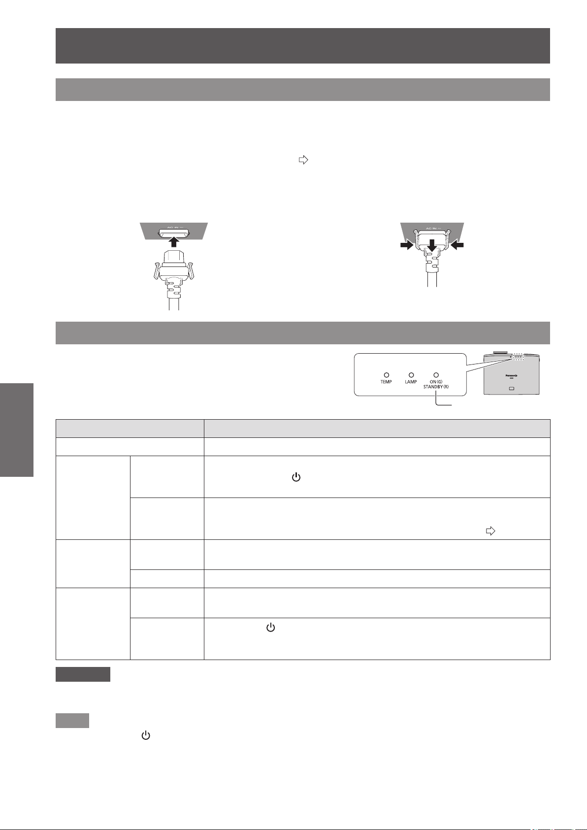
Power cord
Use the power cord included to prevent removal of the power cord and make sure it is fully inserted into
the projector.
Make sure the <MAIN POWER> switch is on the <OFF> side before connecting the power cord.
Use the power cord included and ensure that it is fully inserted.
For power cord handling details, see “Read this rst!”. (
pages
6
to
13)
■
Connecting
Fully insert until the tabs on the left
and right make a click sound.
■
Disconnecting
Pull out while pushing on the tabs on
the sides.
Power indicator
The power indicator indicates the power status.
Check the status of the power indicator <ON (G) / STANDBY (R)>
before operating the projector.
Indicator status Status
No illumination or ashing Main power is switched off.
Red
Lit
Power is switched off. (Standby mode.)
Press the power <
/ | > button to start projection.
* Does not operate when the lamp indicator or temperature indicator is ashing.
Flashing
Power is switched off (standby mode) and the [POWER ON LINK] is set to
[YES] in the VIERA Link settings.
For details about [POWER ON LINK], see [POWER ON LINK] (
page 82).
Green
Flashing
The projector is preparing to project.
Projection starts after a brief pause.
Lit Projecting.
Orange
Lit
Preparing to switch off the power.
The power is switched off after a while. (Changes to the standby mode.)
Flashing
The power <
/ | > button is switched on again in the power off preparation
mode.
Preparing to project. Projection starts after a brief pause.
Attention
z
The internal fan operates and cools the projector while it is preparing to power off (when the power indicator is illuminated
orange). Do not switch the main power off or remove the power cord.
Note
z
When the power < / | > button is pressed while the projector is in the power off preparation mode, it may take some time
to enter projection mode.
z
The projector consumes approx. 0.08 W of electrical power even when the power is off (when the power indicator is
illuminated red).
z
Power consumption when the power indicator ashes red is almost the same as when the lamp is illuminated red.
Power indicator
Switching the projector on/off
ENGLISH
- 29
Basic Operation
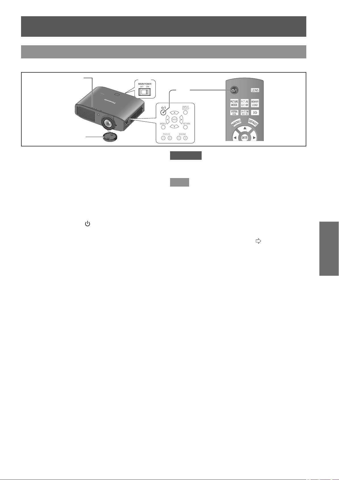
Switching on the projector
Check external device connections before switching the projector on.
Power indicator
4)
3)
5)
1) Connect the power cord to the projector.
2) Connect the power plug to an outlet.
3)
Press the <ON> side of the <MAIN POWER>
switch to turn on the power.
z
The power indicator illuminates or ashes red.
4) Remove the lens cover.
z
Be sure to remove the lens cover before starting
projection.
5) Press the power <
/
|
> button.
z
The power indicator illuminates green after ashing
for a while and projection starts.
Attention
z
Using the projector while the lens cover is attached
causes the device to heat up and can result in a re.
Note
z
When starting up the projector, a small rattling sound
may be heard or when the luminous lamp is lit a tinkling
sound may be heard, but this is not a malfunction.
z
During video projection, the cooling fan operates and
makes a sound. This fan sound may change with
ambient temperature and becomes louder when the lamp
is turned on.
z
Setting the [LAMP POWER] in the [OPTION] menu to
[ECO] reduces operation sounds. (
page 81)
z
When the lamp is turned off and immediately turned back
on again, the video may temporarily icker slightly at the
start of projection due to lamp characteristics. This is not
a malfunction.
Switching the projector on/off
30 -
ENGLISH
Basic Operation
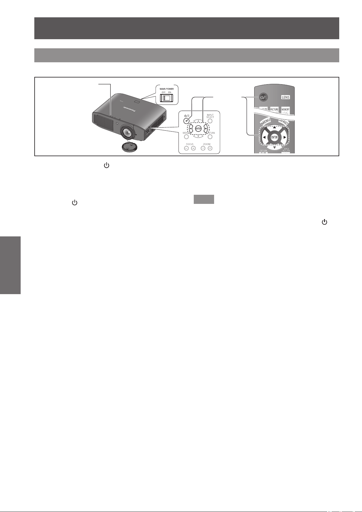
Switching off the power
Carefully check the status of the power indicator before operating.
4)
1) - 3)
Power indicator
1) Press the power <
/ | > button.
z
The conrmation message is displayed.
2) Select [OK] with the
▲
▼
buttons.
3) Press the <ENTER> button (or press the
power <
/ | > button again).
z
The lamp extinguishes and video projection halts.
z
The cooling fan continues to operate and the power
indicator illuminates orange. Wait for the power
indicator to turn red or start ashing red.
4) Press the <OFF> side of the <MAIN
POWER> switch to turn off the power.
z
Never switch off the main power or remove the
power cord when the cooling fan is operating.
Note
z
Select [CANCEL] or press the <MENU> or <RETURN>
button to close the power off conrmation message.
z
The power can also be switched off when the power < / | >
button is held down for 0.5 seconds or more.
Projecting an image
ENGLISH
- 31
Basic Operation
Projecting an image
Check the connections of the external devices
(
page 26) and the connection of the power cord
(
page 28), and switch on the power (
page 29), to
start projecting. Select the video for projection, and
adjust appearance of the projected image.
Selecting the input signal
1) Switch on the external devices.
z
Press the play button on an external device, such
as a Blu-ray player. When [AUTO SEARCH] in the
[OPTION] menu is [ON], the projector automatically
searches for an input signal and starts projection.
(
page 78)
2) Switch the video input.
z
The video selected with the <INPUT SELECT>
button is projected. (
page 34)
Attention
z
The video may not be displayed properly depending on
the external device, or the Blu-ray disc or DVD disc, to
be played back. In such cases, set [TV-SYSTEM], [RGB/
YC
B
C
R
] or [RGB/YP
B
P
R
] of the [ADVANCED MENU].
(
page 57, 58)
z
Check the projection screen and video aspect ratio, and
select the most appropriate aspect ratio with [ASPECT]
in the [POSITION] menu. (
page 61)
Adjusting the image
1) Adjust the angle of the projector.
z
Place the projector parallel to the screen, and
then install it on a at surface so that the screen
becomes rectangle.
z
If the screen is tilted lower than the screen, extend
the adjustable feet to make a rectangle screen.
z
For details, see “Front adjustable feet and throwing
angle”. (
page 23)
2) Remove the lens shift cover.
z
For details, see “Opening the lens shift cover”.
(
page 19)
3) Rotate the lens shift lever in a
counterclockwise direction to disengage
the shift lever lock.
4) Adjust the lens shift.
z
Adjust the projection position with the shift lever.
z
See “Lens shift and positioning”. (
page 24)
5) Rotate the shift lever clockwise to x.
6) Attach the lens shift cover.
7) Managing the lens control settings
z
Press +/− of the <FOCUS> and <ZOOM> buttons
on the device controls to adjust.
Press the <FOCUS> buttons (+/-) to change the
projection size, and press the <ZOOM> buttons
(+/-) again to ne tune the projection size.
<FOCUS> button
<ZOOM> button
Note
z
It is recommended that you display the [ZOOM/FOCUS]
test pattern from the [LENS CONTROL] menu to
accurately adjust the focus (
page 73).This can also be
performed with the remote control. (
page 32)
z
Panasonic recommends that focus adjustment be made
after 30 minutes or more have elapsed since picture
display.
Remote control operation
32 -
ENGLISH
Basic Operation
You can operate the projector with the remote control
within a range of 7 m (23').
z
Operating by pointing at the projector
Ensure the remote control transmitter is facing the remote
control signal receiver on the front of the projector during
use.
z
Facing to the screen
Ensure the remote control transmitter is facing the screen
and press the required buttons to operate the projector.
The signal will be reected off the screen. The operating
range may differ due to the screen material. This function
may not be effective with a translucent screen.
Note
z
Do not let strong light shine onto the signal receiver. The
remote control may malfunction under strong light such
as uorescent light.
z
If there are any obstacles between the remote control
and the remote control signal receiver, the remote control
may not operate correctly.
z
When viewing 3D images the remote control may not
respond well in some cases.
Managing the lens control
settings
You can display [ZOOM/FOCUS] test pattern 1 and
adjust the projection video size and focus.
If you have saved lens memory settings in [LENS
MEMORY SAVE], press the <LENS> button twice to
display [LENS MEMORY LOAD] menu.
Press
Note
z
For details regarding the adjustment method, see [ZOOM/
FOCUS] in the [LENS CONTROL] menu. (
page 73)
Selecting the picture mode
You can switch to your desired picture mode settings.
Press
The settings change as follows each time the button
is pressed.
[NORMAL] [DYNAMIC] [REC709]
[GAME] [CINEMA2] [CINEMA1] [D-CINEMA]
Note
z
You can also switch the picture mode settings using the
on-screen menu.
For details see [PICTURE MODE] in the [PICTURE]
menu. (
page 40)
Adjusting the picture
Switchable setting items from the [PICTURE] menu of
the on-screen menu can be displayed in a list.
Press
Press the button to switch between [PICTURE] menu
and [ADVANCED MENU] menu. Press ▲ ▼ to select
the required menu item and ◄ ► to adjust.
z
[PICTURE] menu items
[PICTURE MODE], [CONTRAST], [BRIGHTNESS],
[COLOR], [TINT], [COLOR TEMPERATURE],
[SHARPNESS ] and [DYNAMIC IRIS]
z
[ADVANCED MENU] menu items
[GAMMA HIGH], [GAMMA MID], [GAMMA LOW],
[CONTRAST], [BRIGHTNESS], [NR], [MPEG NR],
[FRAME CREATION], [x.v.Color], [DETAIL CLARITY],
[CINEMA REALITY], [SUPER WHITE], [TV-SYSTEM],
[RGB/YC
B
C
R
] and [RGB/YP
B
P
R
]
Note
z
For details regarding the adjustment method, see the
[PICTURE] menu (
page 40) and the [ADVANCED
MENU] menu (
page 45).
z
Press the <RETURN> or <MENU> button or wait for 7
seconds without performing any operation to clear the
adjustment screen.
z
Set the [ADJUSTMENT MODE] to [SIMPLE] for adjusting
[GAMMA HIGH], [GAMMA MID], and [GAMMA LOW]
(
page 50).
z
The items for [SHARPNESS] that can be adjusted differ
depending on the [ADJUSTMENT MODE].
[SIMPLE]: [SHARPNESS]
[ADVANCED]: [H-SHARPNESS]
[V-SHARPNESS]
Remote control operation
Remote control operation
ENGLISH
- 33
Basic Operation
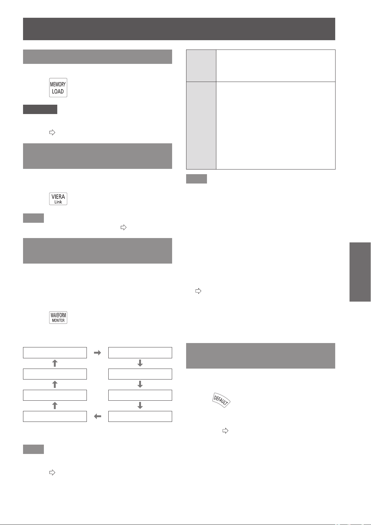
Loading a saved setting
Displays the [MEMORY LOAD] menu.
Press
Attention
z
Setting can also be performed using the on-screen menu.
For details, see [MEMORY LOAD] in the [PICTURE]
menu. (
page 59)
Displaying the [VIERA LINK]
menu
You can control some functions of the external device
with this projector remote control.
Press
Note
z
See “Using VIERA Link” for details. (
page 96)
Displaying the waveform
monitor
By displaying the output signal from a connected
external device with a waveform, you can check if the
video signal (luminance) level is set to a value within
this projector’s recommended range, and can adjust it
accordingly.
Press
The settings change as follows each time the
<ENTER> button is pressed.
[FULL SCAN (Y)] [FULL SCAN (R)]
[SINGLE LINE SCAN (B)] [FULL SCAN (G)]
[SINGLE LINE SCAN (G)] [FULL SCAN (B)]
[SINGLE LINE SCAN (R)] [SINGLE LINE SCAN (Y)]
The waveform monitor disappears when the
<WAVEFORM MONITOR> button is pressed again.
Note
z
Setting can also be performed using the on-screen menu.
For details, see [WAVEFORM MONITOR] in [PICTURE]
menu. (
page 41)
[FULL
SCAN]
Checks that the waveform for each of the
Y- (brightness), R- (red), G- (green), and
B- (blue) values for the whole image is
within the recommended range.
[SINGLE
LINE
SCAN]
Checks that the waveform for each of the
Y- (brightness), R- (red), G- (green), and
B- (blue) values for an arbitrary number
of lines from the top of the screen to the
bottom is within the recommended range.
z
Enables more detailed conrmation than
[FULL SCAN].
z
Line position can be changed with the ▲▼
buttons.
z
The display position of the [WAVEFORM
MONITOR] changes depending on the line
position.
Note
z
Signals lower than 0 % in the waveform monitor will be
displayed as same as 0 % on the projected image.
z
[SINGLE LINE SCAN] can display horizontal lines in Y-
(brightness), R- (red), G- (green), and B- (blue) from the
top of the screen to the bottom more nely than [FULL
SCAN], and each item can be adjusted in the same way
as [FULL SCAN].
z
When selecting [FULL SCAN], the display position of the
waveform can be set using the ▲▼
▲
▼
buttons.
z
So that the display of individual adjustment screen in
[PICTURE] does not interfere with the waveform monitor,
the positioning of this screen differs depending on the
circumstances at the time.
z
The [AUTO ADJUST] is executed by pressing the
<DEFAULT> button while the waveform is displayed.
(
page 42)
z
While the waveform monitor is displayed, you cannot
adjust the [COLOR MANAGEMENT] settings.
z
When a 3D signal is being input (including converting 2D
to 3D), the waveform monitor cannot be displayed.
z
If a 3D signal is input while the waveform monitor is being
displayed, the waveform monitor disappears.
Resetting to the default
settings
You can reset most of the settings or adjustment
values for submenus to factory default settings.
Press
For details, see “Navigating through the menu -
Returning adjusted values to default settings” of “Menu
navigation”. (
page 37)
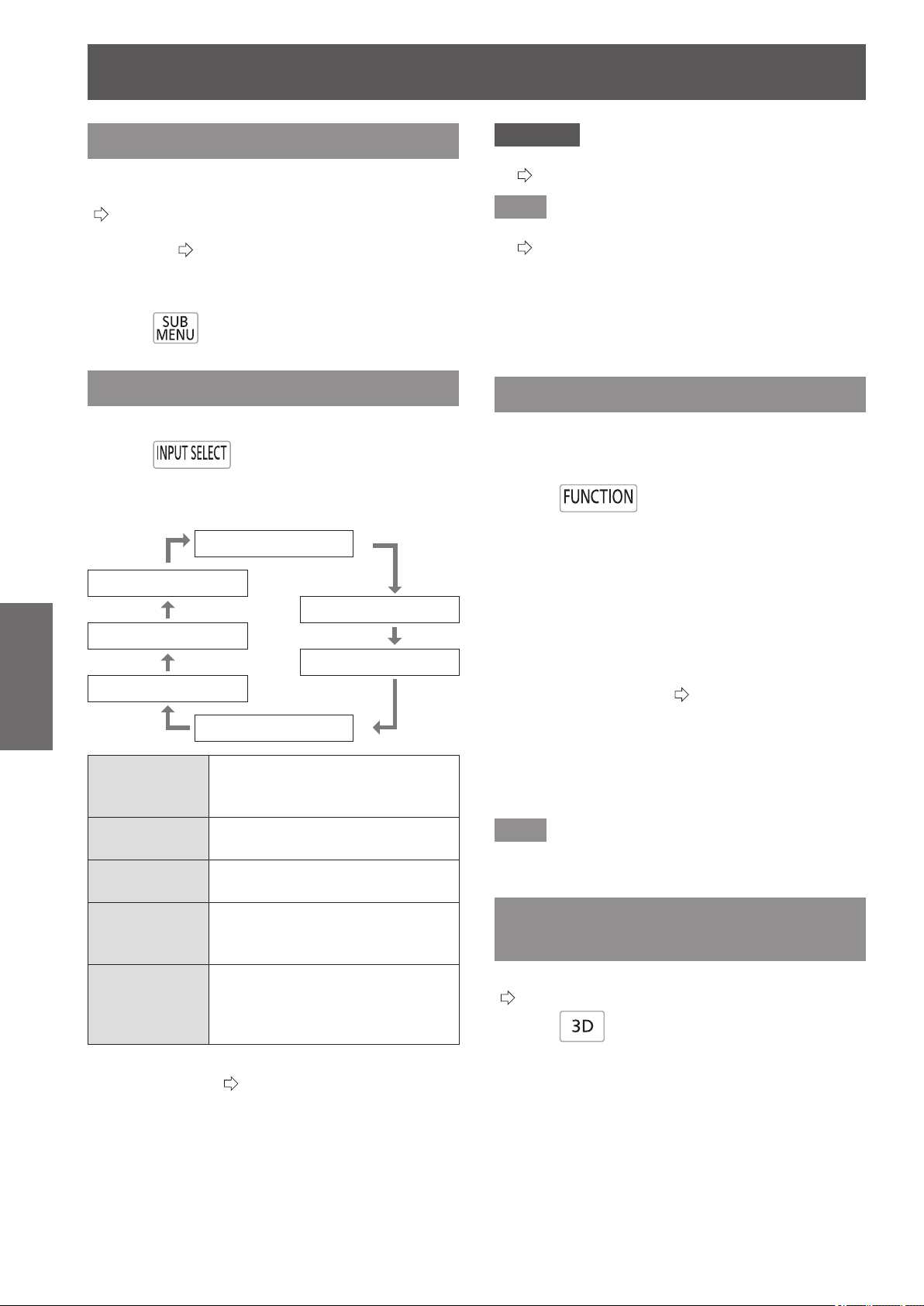
Remote control operation
34 -
ENGLISH
Basic Operation
Submenu
When the VIERA Link control is enabled, the function
menus of external devices can be displayed.
(
page 96)
The operation mode can be changed during gamma
adjustment. (
page 47)
Change the detection level of parallax when the
parallax adjustment monitor is displayed (when
[Mode3] is set).
Press
Switching the input signal
The input for projection can be switched.
Press
The settings change as follows each time the button
is pressed.
[COMPONENT IN]
[COMPUTER IN]
[S-VIDEO IN]
[HDMI 3 IN]
[VIDEO IN]
[HDMI 2 IN]
[HDMI 1 IN]
[COMPONENT
IN]
COMPONENT signals (YC
B
C
R
/
YP
B
P
R
) from the device connected
to COMPONENT IN.
[S-VIDEO IN]
S-VIDEO signal from the device
connected to S-VIDEO IN.
[VIDEO IN]
VIDEO signal from the device
connected to VIDEO IN.
[HDMI 1/2/3 IN]
HDMI signal from the device
connected to
HDMI IN 1/HDMI IN 2/HDMI IN 3.
[COMPUTER IN]
RGB signal and
COMPONENT signals (YC
B
C
R
/
YP
B
P
R
) from the device connected
to COMPUTER IN.
When [INPUT GUIDE] on the [OPTION] menu is
set to [DETAILED] (
page 77), graphical guidance
will be displayed on the upper right of the projected
image, and the currently selected input terminal
can be checked. (The selected input method will be
highlighted in yellow.)
Press the button several times or press ▲ ▼ ◄ ► to
cycle through the input methods.
It may take time for the video to change after
switching input.
Attention
z
Input a signal noted in the “List of compatible signals”.
(
page 100)
Note
z
See “Connecting terminals” regarding input ports.
(
page 20)
z
If no operations are performed for approximately 3
seconds, the input guidance display automatically
disappears.
z
If a port that has no input is selected, the whole input port
graphic ashes. This graphic is displayed until an input is
present.
Using the <FUNCTION> button
Functions used often can be allocated to the
<FUNCTION> button on the remote control and this
can be used as a short cut button.
Press
■
Allocating operations to the
<FUNCTION> button
1) Press the <MENU> button in the controls
of the projector or on the remote control
to display the menu items for allocation
(main menu, submenu, or detailed menu).
z
For how to use the on-screen menu, see “Navigating
through the menu”. (
page 37)
2) Hold the <FUNCTION> button on the
remote control down for at least 3
seconds.
z
After setup is complete the allocated menu items
are displayed under the on-screen menu.
Note
z
While the menu is displayed, the projector does not
operate even when the button is pressed.
Displaying the [3D SETTINGS]
menu
The settings screen for 3D can be displayed.
(
page 64)
Press

Viewing 3D Images
ENGLISH
- 35
Basic Operation
Viewing 3D Images
About viewing 3D images
You can use the projector to view 3D videos by playing
Blu-ray 3D compatible discs on a 3D Blu-ray player.
This projector can also convert 2D videos to 3D for
viewing.
To enjoy stereoscopic 3D images, Panasonic 3D
Eyewear (optional accessory) is necessary. 3D
Eyewear is not included with this projector.
See page 101 for the 3D image signals supported.
Supported 3D Eyewear (as of September 2012)
Panasonic
TY-EW3D3 Series (rechargeable)
TY-EW3D2 Series (rechargeable)
TY-EW3D10 Series (disposable battery)
The product number of the 3D Eyewear differs
depending on the country of purchase.
■
Viewing 3D images
Using the projector menu controls, set so that 3D
images are shown.
z
You can watch 3D images in the following cases:
- When a 3D image supporting Blu-ray disc is played
on a 3D image supporting player/recorder connected
using a HDMI cable to a 3D image supporting
projector.
- 2D->3D (Simulated 3D) (
page 69)
1) Wearing the 3D Eyewear
z
Switches on the 3D Eyewear power.
z
Put on the 3D Eyewear
2) View
z
When the HDMI receives information in which 3D
mode is detected, 3D images are automatically
displayed according to the signal.
z
If the 3D images are not displayed correctly or
the images cause discomfort, the images can be
adjusted by [3D INPUT FORMAT].
3) After Use
z
Switches off the 3D Eyewear power.
Attention
z
Avoid keeping the 3D Eyewear at a location with high
humidity and high temperature. For details on care
and maintenance of 3D Eyewear, see the operating
instructions of 3D Eyewear.
Attention
z
When using 3D Eyewear, also see the operating
instructions of the 3D Eyewear.
z
When viewing 3D videos, be sure to set [3D IR
TRANSMITTER] to one of [STRONG], [MEDIUM],
or [WEAK]. If an external 3D IR Transmitter (optional
accessory) is connected, set the corresponding [TRIGGER
1/2 SETTING] to [3D SHUTTER OUT].(
page 79)
z
When 3D Eyewear is used indoors with uorescent lights
on, the light may appear to icker. In such a case, turn off
the uorescent lights.
z
If the 3D Eyewear is worn upside down or backwards, the
3D video cannot be seen correctly.
z
When viewing 3D display, turn on the power supply for the
3D Eyewear and then put it on.
z
Do not use devices that generate strong electromagnetic
radiation (such as cell phones, handheld radios, etc.)
close to the 3D Eyewear. This may cause the 3D Eyewear
to malfunction.
z
The 3D Eyewear cannot exhibit sufcient performance
at high or low temperatures. Follow the operation
temperature range specied in the operating instructions
for the 3D Eyewear.
z
It may be difcult to view other displays (such as the
computer screen, digital clock, calculators etc.) while
wearing the 3D Eyewear. Remove the 3D Eyewear when
viewing other than 3D videos.
z
When the projector is installed alongside another 3D
compatible display, the 3D videos may appear double
due to the effect of the devices on each other. Install the
projector after thoroughly considering the installation
location.
Note
z
If the 3D Eyewear is worn upside down or backwards, the
3D video cannot be seen correctly.
z
When viewing 3D display, turn on the power supply for the
3D Eyewear and then put it on.
z
The stereoscopic image effect experienced with the 3D
Eyewear may vary with individuals.
z
The projection screen size when displaying 3D videos is
up to 5.08 m (200").
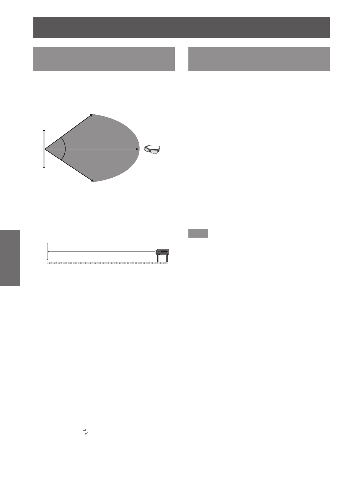
Viewing 3D Images
36 -
ENGLISH
Basic Operation
Communication range of a 3D
IR Transmitter and 3D Eyewear
The IR signals for controlling the 3D Eyewear
transmitted from the 3D IR Transmitter reach the 3D
Eyewear after being reected by the screen.
The communication range between the 3D IR
Transmitter and 3D Eyewear is as shown below.
Screen
3D Eyewear
Approx. 5 m (16'5")
Approx. 4 m (13'1")
Approx. 4 m (13'1")
The diagram above shows the communication range
under the following conditions:
- When the distance between the projector and the screen is
6 m (19'8").
- When the projector is arranged in front of the screen
without performing lens shift.
Screen
6 m
(19'8")
- When using a 2.54 m (100"), screen gain [1], diffuser
screen.
- When [3D IR TRANSMITTER] is set to [STRONG].
- When there is no effect of strong light from the sun or from
a uorescent lamp.
Note that the communication range may differ greatly depending
on the type and material of the screen.
z
The 3D Eyewear may not correctly receive infrared control
signal in the following cases.
- When there is an obstacle between the projector and the
screen.
- When dirt or dust has accumulated on the 3D Eyewear
transmitter.
- When the 3D Eyewear is not facing the screen.
z
Remove the lens shift cover if you cannot see 3D video.
The communication range may increase.
z
If you wish to view 3D images in an environment that does
not full the previously noted conditions, please purchase
an external 3D IR Transmitter (optional accessory).
z
If communication between the 3D IR Transmitter and 3D
Eyewear is lost, either recharge or replace the battery of
the 3D Eyewear. (
page 94)
Cautions when using 3D
Eyewear
z
Do not use devices that generate strong electromagnetic
radiation (such as cell phones, handheld radios, etc.)
close to the 3D Eyewear. This may cause the 3D
Eyewear to malfunction.
z
Do not expose the 3D Eyewear to direct sunlight,
uorescent light or other strong light as 3D video may not
be viewed correctly in some cases.
z
The 3D Eyewear cannot exhibit sufcient performance at
high or low temperature.
Follow the operation temperature range noted in the
operating instructions for the 3D Eyewear.
z
Wear the 3D Eyewear correctly. If they are worn upside
down or backwards, the solid body image will not be
seen correctly.
z
It may be difcult to view other displays (such as the
computer screen, digital clock, calculators etc.) while
wearing the 3D Eyewear. Remove the 3D Eyewear when
viewing other than 3D videos.
z
Rechargeable 3D Eyewear cannot be charged with
this projector. If you do not have a Panasonic 3D TV,
use a charger that has a USB2.0 port for charging your
Eyewear. The recommended charger is Apple USB
Power Adapter for iPhone.
Note
z
After nishing the 3D video, place the 3D Eyewear in
their glass case and store avoiding places with high
humidity and high temperature.
z
Please see the operating instructions for the 3D Eyewear
regarding cleaning of the 3D Eyewear.
z
While wearing 3D Eyewear and viewing 3D movies under
a modulated uorescent light, your eld of vision may be
tinted red or blue in cycles of 2 - 3 seconds. Change the
brightness of the light so that it does not have any effect
on viewing.
35 °
35 °
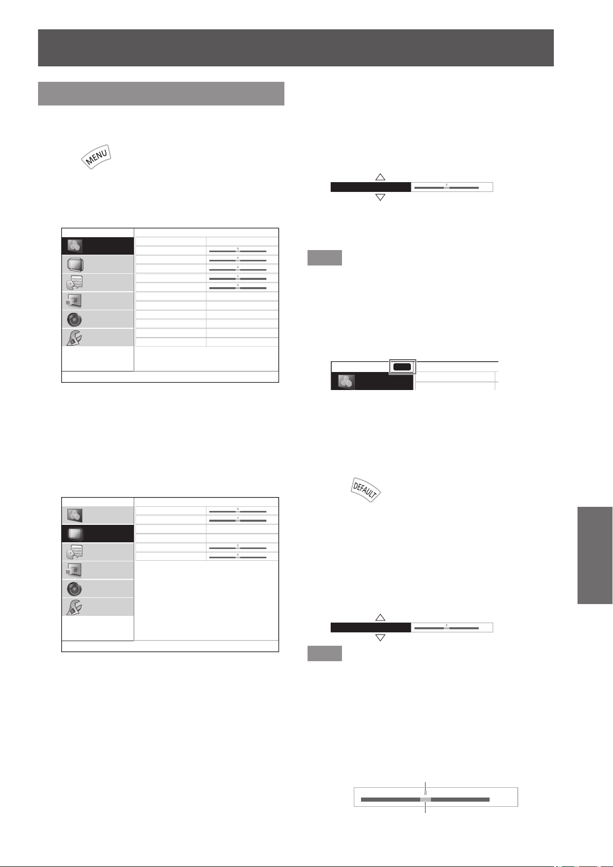
Menu navigation
ENGLISH
- 37
Settings
Menu navigation
Navigating through the menu
■
Operating procedure
Press
1) Press the <MENU> button on the remote
control or in the controls of the projector.
z
The main menu is displayed.
PICTURE MODE
CONTRAST
BRIGHTNESS
COLOR
TINT
COLOR TEMPERATURE
SHARPNESS
DYNAMIC IRIS
WAVEFORM MONITOR
SPLIT ADJUST
ADVANCED MENU
PICTURE MEMORY
NORMAL
SIMPLE
ON
0
0
0
0
0
PICTURE
POSITION
LANGUAGE
3D SETTINGS
LENS CONTROL
OPTION
2) Press the ▲▼ buttons to select main
menu items.
z
Select the item to be adjusted from the 6 items
[PICTURE], [POSITION], [LANGUAGE], [3D
SETTINGS], [LENS CONTROL] and [OPTION].
The selected item is indicated with a yellow cursor,
and the submenu is displayed on the right hand
side.
H-POSITION
V-POSITION
ASPECT
WSS
OVER SCAN
KEYSTONE
16:9
ON
0
0
0
0
PICTURE
POSITION
LANGUAGE
3D SETTINGS
LENS CONTROL
OPTION
3) Press the <ENTER> button.
z
The submenu is displayed, and submenu items
become selectable.
4) Press the ▲▼ buttons to select the
submenu item you wish to alter, then
press the
▲
▼
to switch settings/adjust.
z
For items where the setting is switched or that have
a bar scale, the menu screen disappears and only
the selected item (individual adjustment screen) is
displayed, as shown in the diagram below.
H-POSITION 0
z
For items that are only names, pressing the
<ENTER> button displays the next screen and
advanced settings can be performed.
Note
z
Pressing the <RETURN> or <MENU> button when the
menu screen is displayed returns to the previous screen.
z
Depending on the signal input, some items may not be
adjustable and some functions may not be usable.
z
Some items can be adjusted even if a signal is not input.
z
See page 38 for the submenu items.
z
When a 3D image is being displayed, the “3D icon” can
be seen at the top left of the menu screen.
0
0
0
0
0
3D
■
Returning adjusted values to default
settings
Press the <DEFAULT> button on the remote control
to return the settings/adjustment values to default
settings.
Press
This function differs depending on the screen displayed.
●
When the submenu screen is displayed:
The submenu items displayed are returned to
their default settings.
●
When individual adjustment screen is displayed:
Only the item currently being adjusted is returned
to its default settings.
H-POSITION 0
Note
z
All settings cannot be simultaneously returned to default
settings.
z
Some items do not return to default settings even you
press the <DEFAULT> button. Please set those items
individually.
z
The vertical bar above the bar scale on the individual
adjustment screen indicates the default setting.
The position of the vertical bar varies depending on the
input signal.
0
Current setting
Default setting
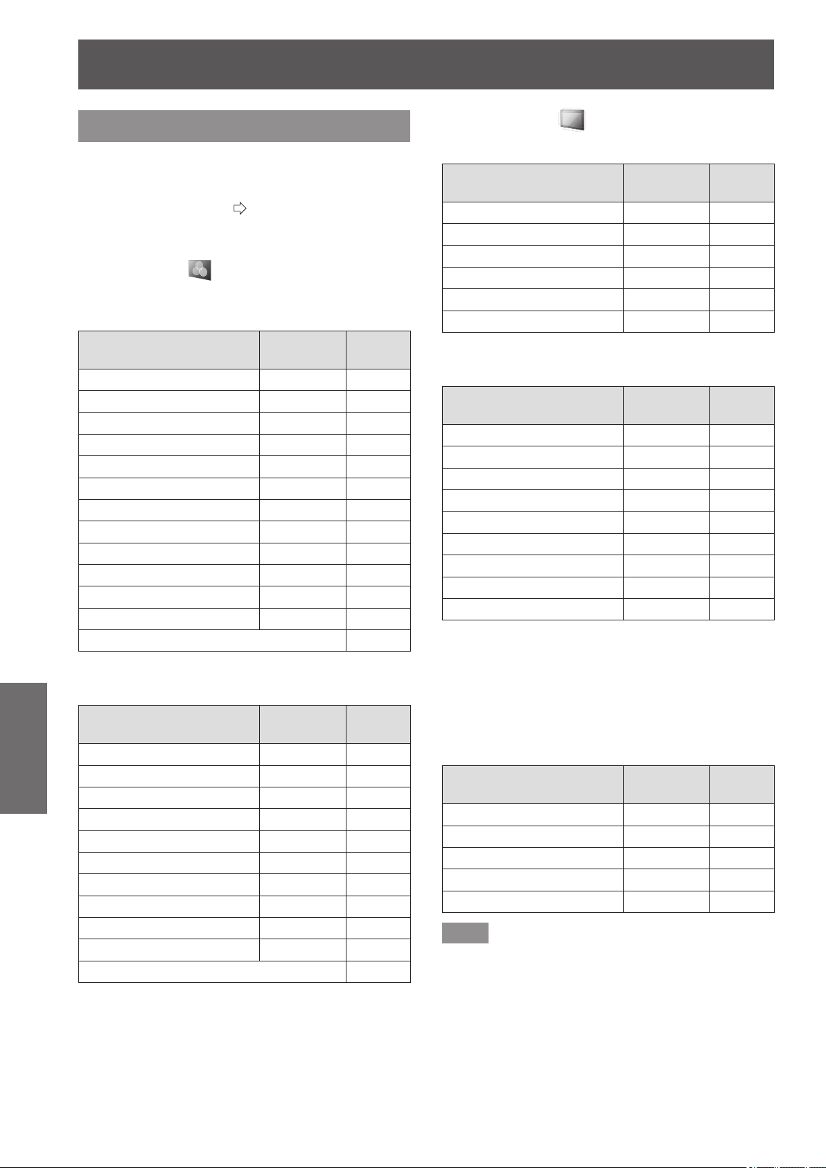
Menu navigation
38 -
ENGLISH
Settings
Menu list
The on-screen menu is used for settings and
adjustments on this projector.
See “Navigating through the menu” for details of on-
screen menu operation. (
page 37)
The submenu of the main menu is displayed, and
setting/adjustment for each item can be performed.
■
[PICTURE]
●
S-VIDEO IN/VIDEO IN/COMPONENT (YC
B
C
R
/
YP
B
P
R
) signal input/HDMI
Submenu items
Default
setting
Page
[PICTURE MODE] [NORMAL] 40
[CONTRAST] [0] 40
[BRIGHTNESS] [0] 40
[COLOR] [0] 40
[TINT] [0] 40
[COLOR TEMPERATURE] [0] 41
[SHARPNESS] [SIMPLE] 41
[DYNAMIC IRIS] [ON] 41
[WAVEFORM MONITOR] — 41
[SPLIT ADJUST] — 44
[ADVANCED MENU] — 45
[PICTURE MEMORY] — 58
SIGNAL MODE
*1
59
*1: COMPONENT IN/HDMI IN only
●
COMPUTER (RGB) signal input
Submenu items
Default
setting
Page
[PICTURE MODE] [NORMAL] 40
[CONTRAST] [0] 40
[BRIGHTNESS] [0] 40
[COLOR TEMPERATURE] [0] 41
[SHARPNESS] [SIMPLE] 41
[DYNAMIC IRIS] [ON] 41
[WAVEFORM MONITOR] — 41
[SPLIT ADJUST] — 44
[ADVANCED MENU] — 45
[PICTURE MEMORY] — 58
SIGNAL MODE 59
■
[POSITION]
●
S-VIDEO IN/VIDEO IN
Submenu items
Default
setting
Page
[H-POSITION] [0] 60
[V-POSITION] [0] 60
[ASPECT] [AUTO] 61
[WSS]
*1
[ON] 63
[OVER SCAN] [+7] 63
[KEYSTONE] [0] 63
*1: PAL signal input only
●
COMPONENT IN/COMPUTER IN
Submenu items
Default
setting
Page
[H-POSITION] [0] 60
[V-POSITION] [0] 60
[DOT CLOCK]
*1
[0] 60
[CLOCK PHASE]
*2
[0] 60
[ASPECT] [16:9] 61
[WSS]
*3
[ON] 63
[OVER SCAN]
*4
[0] 63
[KEYSTONE] [0] 63
[AUTO SETUP]
*5
— 63
*1: COMPUTER IN only (exc. 480i, 576i, 480p, 576p)
*2: Exc. 480i/576i
*3: COMPONENT IN (576i, 576p) only
*4: COMPONENT IN and COMPUTER signal (movie
based signals) input only
*5: COMPUTER IN (RGB) signals only (exc. movie
based signals)
●
HDMI IN
Submenu items
Default
setting
Page
[H-POSITION] [0] 60
[V-POSITION] [0] 60
[ASPECT] [16:9] 61
[OVER SCAN] [0] 63
[KEYSTONE] [0] 63
Note
z
The default settings may be different depending on the
picture menu.
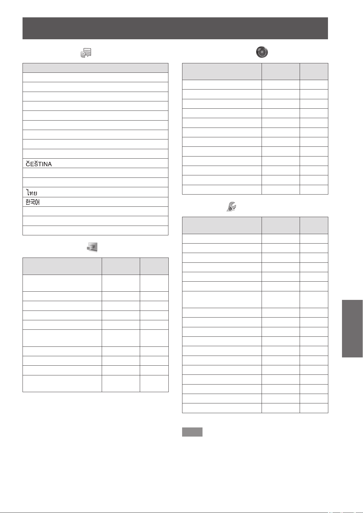
Menu navigation
ENGLISH
- 39
Settings
■
[LANGUAGE]
Language
[DEUTSCH]
[FRANÇAIS]
[ESPAÑOL]
[ITALIANO]
[PORTUGUÊS]
[SVENSKA]
[NORSK]
[DANSK]
[POLSKI]
[
]
[MAGYAR]
[РУССКИЙ]
[
]
[
]
[ENGLISH]
[
中文
]
[
日本語
]
■
[3D SETTINGS]
Submenu items
Default
setting
Page
[SCREEN SIZE]
[203 cm
(80 inches)]
64
[3D INPUT FORMAT] [AUTO] 64
[LEFT/RIGHT SWAP] [NORMAL] 66
[3D PICTURE BALANCE] — 66
[2D TO 3D]
[OFF] 69
[3D EYEWEAR
BRIGHTNESS]
[NORMAL] 70
[3D IR TRANSMITTER] [STRONG] 70
[3D VIEWING MONITOR] [MODE1] 71
[3D MOTION REMASTER] [ON] 72
[3D SAFETY
PRECAUTIONS]
— 72
■
[LENS CONTROL]
Submenu items
Default
setting
Page
[ZOOM/FOCUS] — 73
[LENS MEMORY LOAD] — 73
[LENS MEMORY SAVE] — 74
[LENS MEMORY EDIT] — 74
[AUTO SWITCHING]
— 75
[H-AREA POSITION] [0] 76
[V-AREA POSITION] [0] 76
[LEFT MASKING AREA] [0] 76
[RIGHT MASKING AREA] [0] 76
[UPPER MASKING AREA] [0] 76
[LOWER MASKING AREA] [0] 76
[PROCESSING MESSAGE] [ON] 76
■
[OPTION]
Submenu items
Default
setting
Page
[ON-SCREEN DISPLAY] — 77
[BACK COLOR] [BLUE] 77
[STARTUP LOGO] [ON] 78
[AUTO SEARCH] [ON] 78
[HDMI SIGNAL LEVEL]
*1
[NORMAL] 78
[FRAME RESPONSE] [NORMAL] 78
[PROJECTION METHOD]
[FRONT/
DESK]
78
[TRIGGER 1 SETTING] [OFF] 79
[TRIGGER 2 SETTING] [OFF] 79
[SLEEP] [OFF] 80
[HIGH ALTITUDE MODE] [OFF] 80
[LAMP POWER] [NORMAL] 81
[FUNCTION BUTTON] — 81
[VIERA LINK SETTINGS] — 81
[OTHER FUNCTIONS] — 83
[TEST PATTERN] — 83
[LAMP RUNTIME] — 83
[INITIALIZE ALL] — 84
*1: HDMI IN only
Note
z
Display of submenu items and default settings differs
depending on the selected input port.
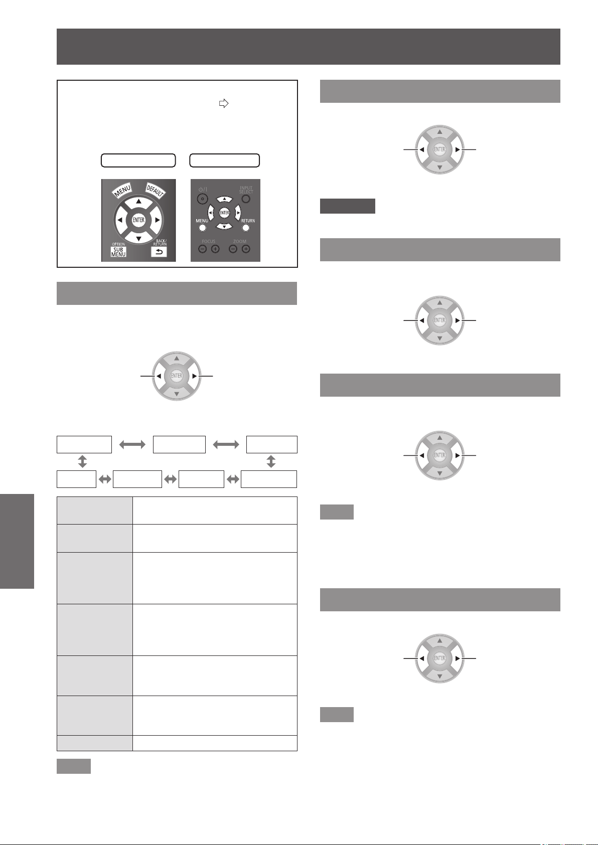
[PICTURE] menu
40 -
ENGLISH
Settings
Select [PICTURE] from the main menu of
“Navigating through the menu” (
page 37),
and choose an item from the submenu.
z
After selecting an item, adjust the image with the
▲
▼
buttons.
Remote control
Projector controls
[PICTURE MODE]
You can use these preset parameter settings to
optimize image projection according to image source
or projection environment.
Switch settings Switch settings
The settings change as follows each time the button
is pressed.
[NORMAL] [DYNAMIC]
[REC709]
[GAME] [CINEMA2] [CINEMA1] [D-CINEMA]
[NORMAL]
For a general image such as sports
program.
[DYNAMIC]
For viewing at high brightness and
sharpness.
[REC709]
For HDTV standard (ITU-R BT.
709) color temperature 6 500 K at
the default setting of the [PICTURE]
menu items.
[D-CINEMA]
For D-CINEMA standard (SMPTE
RP431-2) color temperature
6 300 K at the default setting of the
[PICTURE] menu items.
[CINEMA1]
Tuned by top Hollywood colorists
for watching a movie with smooth
image quality.
[CINEMA2]
For viewing action lms and anime
etc. with vivid color and sharp
quality.
[GAME] For use with games.
Note
z
It may take a few seconds for the picture to stabilize after
a picture mode change.
[CONTRAST]
You can adjust the contrast of the colors.
Lower
Higher
z
Setting range: -64 to +64
Attention
z
Adjust the [BRIGHTNESS] in advance if necessary.
[BRIGHTNESS]
You can adjust the dark (black) part of the projected
image.
Darker
Brighter
z
Setting range: −32 to +32
[COLOR]
You can adjust the color saturation of the projected
image.
Lighter
Darker
z
Setting range: −32 to +32
Note
z
When COMPUTER signal is input, only movie based
signals can be adjusted.
z
Movie based signals are 480i, 576i, 480p, 576p, 720/60p,
720/50p, 1 080/60i, 1 080/50i, 1 080/60p, 1 080/50p and
1 080/24p.
[TINT]
You can adjust the skin tone in the projected image.
Less greenish
Less reddish
z
Setting range: −32 to +32
Note
z
When COMPUTER signal is input, only movie based
signals can be adjusted.
z
Movie based signals are 480i, 576i, 480p, 576p, 720/60p,
720/50p, 1 080/60i, 1 080/50i, 1 080/60p, 1 080/50p and
1 080/24p.
[PICTURE] menu
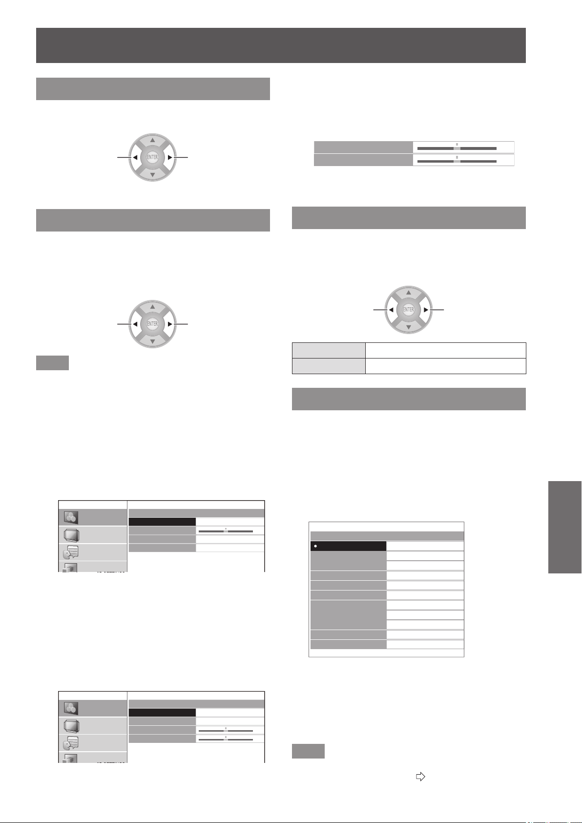
[PICTURE] menu
ENGLISH
- 41
Settings
[COLOR TEMPERATURE]
You can adjust the color temperature if the white
areas of the projected image are bluish or reddish.
Less bluish
Less reddish
z
Setting range: -6 to +6
[SHARPNESS]
With regards to the input signal, adjust video
sharpness using one of [SIMPLE] which adjusts
horizontal direction and vertical direction
simultaneously or [ADVANCED] which adjusts each
individually.
Softer
Sharper
Note
z
Setting range will vary according to the selected input
signal.
z
[SHARPNESS] can be adjusted using either [SIMPLE] or
[ADVANCED]. Both settings cannot be used at the same
time.
z
Adjusting the [SHARPNESS].
(When [SIMPLE] is selected for the
[ADJUSTMENT MODE].)
1) Press
▲
▼
buttons to select [SIMPLE].
SHARPNESS
ADJUSTMENT MODE
SHARPNESS
H-SHARPNESS
V-SHARPNESS
SIMPLE
0
PICTURE
POSITION
LANGUAGE
3D SETTINGS
2) Select [SHARPNESS] with the ▲▼
buttons, and adjust with the
▲
▼
buttons.
z
Adjusting the [SHARPNESS].
(When [ADVANCED] is selected for the
[ADJUSTMENT MODE].)
1) Press the ◄► buttons to select
[ADVANCED].
SHARPNESS
ADJUSTMENT MODE
SHARPNESS
H-SHARPNESS
V-SHARPNESS
ADVANCED
0
0
PICTURE
POSITION
LANGUAGE
3D SETTINGS
2) Select item with the ▲▼ buttons, and
adjust with the
▲
▼
buttons.
z
Pressing the ▲▼ buttons on the screen during
adjustment switches to the [H-SHARPNESS] or
[V-SHARPNESS] adjustment screen.
H-SHARPNESS
V-SHARPNESS
0
0
z
The setting range varies according to the selected
picture mode and input signal.
[DYNAMIC IRIS]
You can switch automatic adjustment of the lamp and
the lens iris on/off. This augments the video to create
a video expression with sharp contrast between light
and shade.
Switch settings Switch settings
[ON] Automatic adjustment
[OFF] No adjustment
[WAVEFORM MONITOR]
By using a commercial test disk etc. and setting the
luminance level of the output (brightness) signal from
a connected external device to a value within this
projector’s recommended range, you can perform
adjustment so the display performance of the projector
can be fully leveraged.
1) Press the <ENTER> button.
z
The [WAVEFORM MONITOR] menu is displayed.
WAVEFORM MONITOR
OFF
FULL SCAN(Y)
FULL SCAN(R)
FULL SCAN(G)
FULL SCAN(B)
SINGLE LINE SCAN(Y)
SINGLE LINE SCAN(R)
SINGLE LINE SCAN(G)
SINGLE LINE SCAN(B)
MONITOR POSITION
AUTO ADJUST
UPPER LEFT
2) Press the ▲▼ buttons to select the
required item.
z
Select [OFF] to close the waveform monitor.
3) Press the <ENTER> button.
z
The waveform monitor is displayed.
Note
z
For details, see “Displaying the waveform monitor” in
“Remote control operation”. (
page 33)
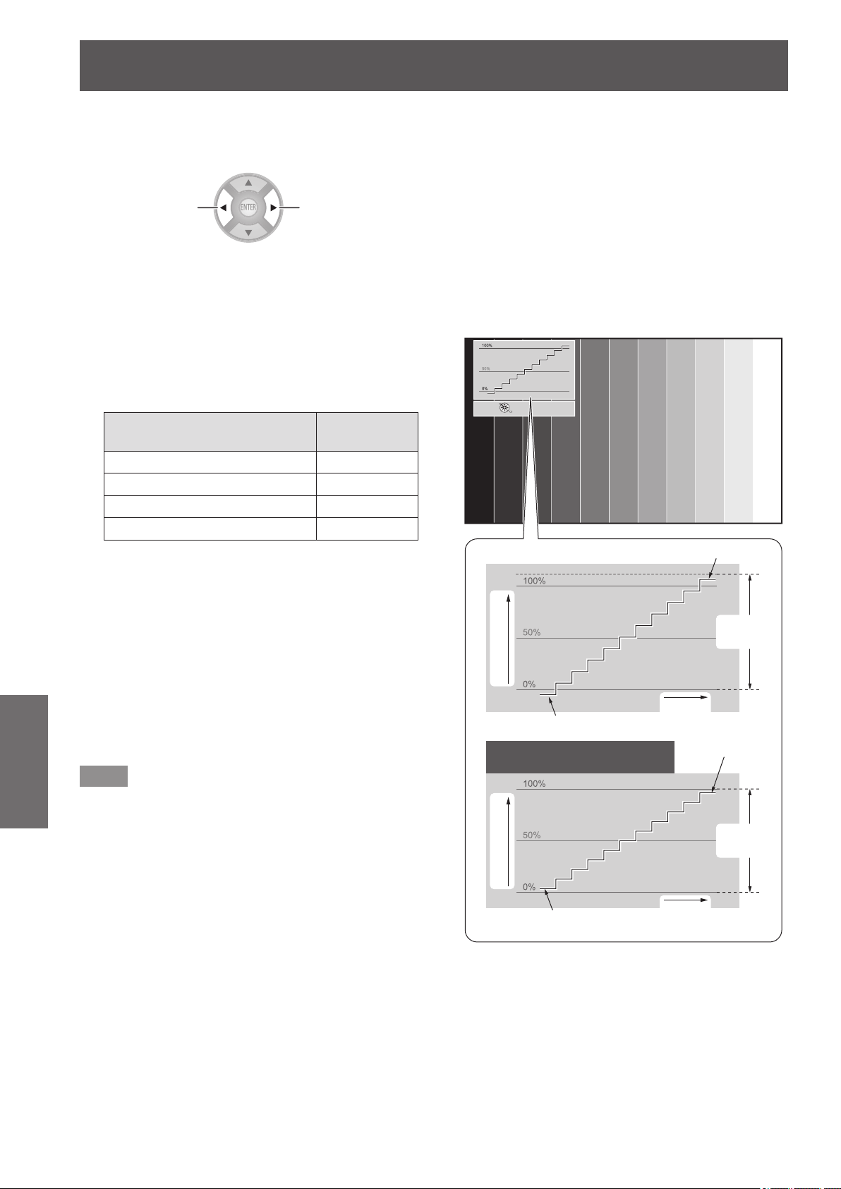
[PICTURE] menu
42 -
ENGLISH
Settings
■
[MONITOR POSITION]
You can set the display position of the input waveform
during the FULL SCAN display.
Switch settings Switch settings
■
[AUTO ADJUST]
The luminance level of the output signal from a connected
external device is automatically adjusted by setting the
automatic waveform adjustment items.
1) Press the <ENTER> button.
2) Press the ▲▼ buttons to select the
required item.
Automatic waveform
adjustment items
Default
setting
[BLACK LEVEL ADJUST] [ON]
[WHITE LEVEL ADJUST] [ON]
[RGB ADJUST (BLACK)] [OFF]
[RGB ADJUST (WHITE)] [OFF]
3) Press the ◄► buttons to switch
adjustment.
4) Press the ▲▼ buttons to select [START
AUTO ADJUST] and press the <ENTER>
button.
z
[PROCESSING] message is displayed. When
adjustment is complete, a conrmation message for
applying results is displayed.
5) Select [OK] with the
▲
▼
buttons.
6) Press the <ENTER> button.
Note
z
When [BLACK LEVEL ADJUST] is [ON], the display
signal Y (brightness) value’s black level is automatically
adjusted to the 0% position.
z
When [WHITE LEVEL ADJUST] is [ON], the display
signal Y (brightness) value’s white level is automatically
adjusted to the 100% position.
z
When [RGB ADJUST (BLACK)] is [ON], the display signal
R (Red), G (Green), and B (Blue) value’s black level are
all automatically adjusted to the 0% position.
z
When [RGB ADJUST (WHITE)] is [ON], the display signal
R (Red), G (Green), and B (Blue) value’s white level are
all automatically adjusted to the 100% position.
z
[AUTO ADJUST] cannot be executed if the [WAVEFORM
MONITOR] is [OFF].
z
Project the luminance adjustment signal of a commercial
test disk etc., and perform automatic adjustment.
However, even with an adjustment disk, correct
adjustment may not be possible if noise is included on
the disk itself or the playback device generates noise.
z
[AUTO ADJUST] adjusts based on the 0% and 100%
standard signal within the screen, so correct adjustment
cannot be performed if standard signals are not displayed
on the screen because of overscan etc., or if a signal that
is less than 0% or greater than 100% is displayed on the
screen.
z
When 3D is being displayed (including converting 2D to
3D), the [WAVEFORM MONITOR] cannot be executed.
■
Adjust the waveform
Project the brightness adjustment signal of a commercial
test disk (0% [0 IRE or 7.5 IRE] - 100% [100 IRE] ) and
perform adjustment.
RETURN
MOVE DISPLAY
CHANGE WF MODE
Adjust to 100%
Signal (luminance) level
Signal (luminance) level
Monitor
position
Monitor
position
Adjust to 100%
Adjust to 0 %
With COMPUTER (except 1 080
signal) or HDMI (Expand)
Adjust to 0 %
Image
displayable
area
Image
displayable
area
With the [WAVEFORM MONITOR] displayed, press the
<MENU> button on the remote control and adjust using
[ADVANCED MENU] and [PICTURE] from the on-screen
menu.
[PICTURE] menu
ENGLISH
- 43
Settings
1) Adjust [FULL SCAN(Y)] / [SINGLE LINE
SCAN(Y)].
z
Set on [PICTURE] and use the
▲
▼
buttons to
adjust [BRIGHTNESS] and then [CONTRAST].
[BRIGHTNESS]
Adjust the bottom line of the
waveform to 0 %
(0 or 7.5 IRE)
z
Setting range:
−32 to +32
[CONTRAST]
Adjust the top line of the
waveform to 100 %
(100 IRE)
z
Setting range:
−64 to +64
2) Adjust [FULL SCAN(R)] / [SINGLE LINE
SCAN(R)].
z
Set on [ADVANCED MENU] and use the
▲
▼
buttons to adjust [BRIGHTNESS R] and then
[CONTRAST R].
[BRIGHTNESS R]
Adjust the bottom line of the
waveform to 0 %
(0 or 7.5 IRE)
z
Setting range:
−16 to +16
[CONTRAST R]
Adjust the top line of the
waveform to 100 %
(100 IRE)
z
Setting range:
−32 to +32
3) Adjust [FULL SCAN(G)] / [SINGLE LINE
SCAN(G)].
z
Set on [ADVANCED MENU] and use the
▲
▼
buttons to adjust [BRIGHTNESS G] and then
[CONTRAST G].
[BRIGHTNESS G]
Adjust the bottom line of the
waveform to 0 %
(0 or 7.5 IRE)
z
Setting range:
−16 to +16
[CONTRAST G]
Adjust the top line of the
waveform to 100 %
(100 IRE)
z
Setting range:
−32 to +32
4) Adjust [FULL SCAN(B)] / [SINGLE LINE
SCAN(B)].
z
Set on [ADVANCED MENU] and use the
▲
▼
buttons to adjust [BRIGHTNESS B] and then
[CONTRAST B].
[BRIGHTNESS B]
Adjust the bottom line of the
waveform to 0 %
(0 or 7.5 IRE)
z
Setting range:
−16 to +16
[CONTRAST B]
Adjust the top line of the
waveform to 100 %
(100 IRE)
z
Setting range:
−32 to +32
Note
z
When a 3D signal is being input (including converting
2D to 3D), the [WAVEFORM MONITOR] cannot be
executed.
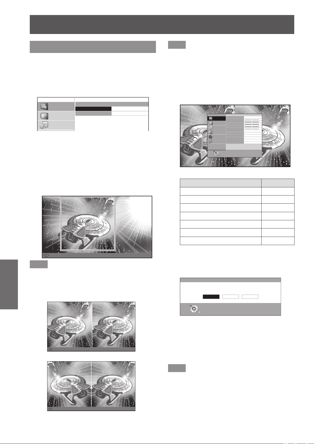
[PICTURE] menu
44 -
ENGLISH
Settings
[SPLIT ADJUST]
You can perform image adjustment for some
[PICTURE] menu items while displaying a certain
area of the frozen image in a split window.
1) Press the <ENTER> button.
z
The [SPLIT ADJUST] menu is displayed.
SPLIT ADJUST
AREA SELECT
SPLIT ADJUST MODE
NORMAL
PICTURE
POSITION
LANGUAGE
2) Press the ▲▼ buttons to select [AREA
SELECT] and then press the <ENTER>
button.
z
The image is frozen and an area for adjustment is
displayed. The image being projected is recorded
and displayed as a frozen image.
3) Use the
▲
▼
buttons to select the area to
be adjusted.
MOVE AREA ENTER : GO TO SPLIT ADJUST RETURN : GO TO FREEZE SCREEN
Note
z
Press the <RETURN> button, and a frozen screen is
displayed.
4) Press the <ENTER> button.
z
Split screen display begins.
MENU : GO TO PICTURE MENU ENTER : ADJUSTMENT COMPLETE RETURN : GO TO AREA SELECT
MENU : GO TO PICTURE MENU ENTER : ADJUSTMENT COMPLETE RETURN : GO TO AREA SELECT
[When [SPLIT ADJUST MODE] is [NORMAL]]
[When [SPLIT ADJUST MODE] is [REVERSE]]
Note
z
By selecting the [SPLIT ADJUST MODE] with the ▲▼
buttons and switching [NORMAL] to [REVERSE], the
screen displayed on the left during split screen display
can be reversed and adjusted.
5) Press the <MENU> button and make
adjustments with the [PICTURE] menu.
z
The menu screen is displayed. You can adjust the
image for optimal display.
PICTURE MODE
CONTRAST
BRIGHTNESS
COLOR
TINT
COLOR TEMPERATURE
SHARPNESS
DYNAMIC IRIS
WAVEFORM MONITOR
SPLIT ADJUST
ADVANCED MENU
PICTURE MEMORY
SIMPLE
0
0
0
0
0
PICTURE
POSITION
LANGUAGE
3D SETTINGS
LENS CONTROL
OPTION
F
RETURN
FUNCTION
DISABLE
ENTER
SELECT
z
Items that can be adjusted
Submenu items Page
[CONTRAST] 40
[BRIGHTNESS] 40
[COLOR] 40
[TINT] 40
[COLOR TEMPERATURE] 41
[SHARPNESS] 41
[ADVANCED MENU] 45
6) Press the <RETURN> button until getting
back to the adjustment screen.
7) Press the <ENTER> button.
SPLIT ADJUST
SAVE CHANGES?
YES : SAVE AND QUIT
NO : QUIT WITHOUT SAVING
CANCEL : ADJUST AGAIN
CANCELYES NO
RETURN
SELECT
ENTER
z
The conrmation message is displayed.
Select [YES] with the ◄► buttons and press the
<ENTER> button to apply the changes and return
to the frozen screen.
Select [NO] with the ◄► buttons and press the
<ENTER> button to return to the frozen screen
without applying changes.
Note
z
Select [CANCEL] on the conrmation message and press
the <ENTER> button to return to the adjustment screen.
8) Press the <RETURN> button.
z
You can now view the projected video with the
adjustments applied.

[PICTURE] menu
ENGLISH
- 45
Settings
Note
z
You cannot adjust menu items that are displayed in grey
during split adjustment.
z
The [KEYSTONE] of [POSITION] becomes inactive
during split adjustment.
z
When a 3D signal is being input (including converting 2D
to 3D), the [SPLIT ADJUST] cannot be executed.
[ADVANCED MENU]
You can perform more detailed image adjustment
manually.
Press the <ENTER> button
z
The [ADVANCED MENU] menu is displayed.
ADVANCED MENU
GAMMA ADJUSTMENT
CONTRAST R
CONTRAST G
CONTRAST B
BRIGHTNESS R
BRIGHTNESS G
BRIGHTNESS B
NR
MPEG NR
FRAME CREATION
COLOR MANAGEMENT
x.v.Color
DETAIL CLARITY
ADVANCED 1
MODE1
NORMAL
0
0
0
0
0
0
0
0
+3
PICTURE
POSITION
LANGUAGE
3D SETTINGS
LENS CONTROL
OPTION
■
[GAMMA ADJUSTMENT]
You can make detailed adjustments to the light intensity
of each input signal level by using the [ADVANCED1] -
[ADVANCED8] mode, or adjust at 3 levels (high, mid, low)
by using the [SIMPLE] mode.
Note
z
You can only carry out the [GAMMA ADJUSTMENT]
through either the [ADVANCED1] - [ADVANCED8] or
[SIMPLE] mode. Both modes cannot be used at the
same time.
●Adjusting the gamma
(when [ADVANCED1] – [ADVANCED8] is
selected in the [ADJUSTMENT MODE])
1) Press the
▲▼
buttons to select
[GAMMA ADJUSTMENT], and press the
<ENTER> button.
z
The [GAMMA ADJUSTMENT] menu appears.
2) Press the
▲▼
buttons to select
[ADJUSTMENT MODE], and then press
the
◄►
buttons to select any one from
[ADVANCED1] through [ADVANCED8].
GAMMA ADJUSTMENT
ADJUSTMENT MODE
GAMMA HIGH
GAMMA MID
GAMMA LOW
START ADJUSTMENT
GAMMA NAME CHANGE
INITIALIZE
ADVANCED1
PICTURE
POSITION
LANGUAGE
3D SETTINGS
LENS CONTROL
OPTION
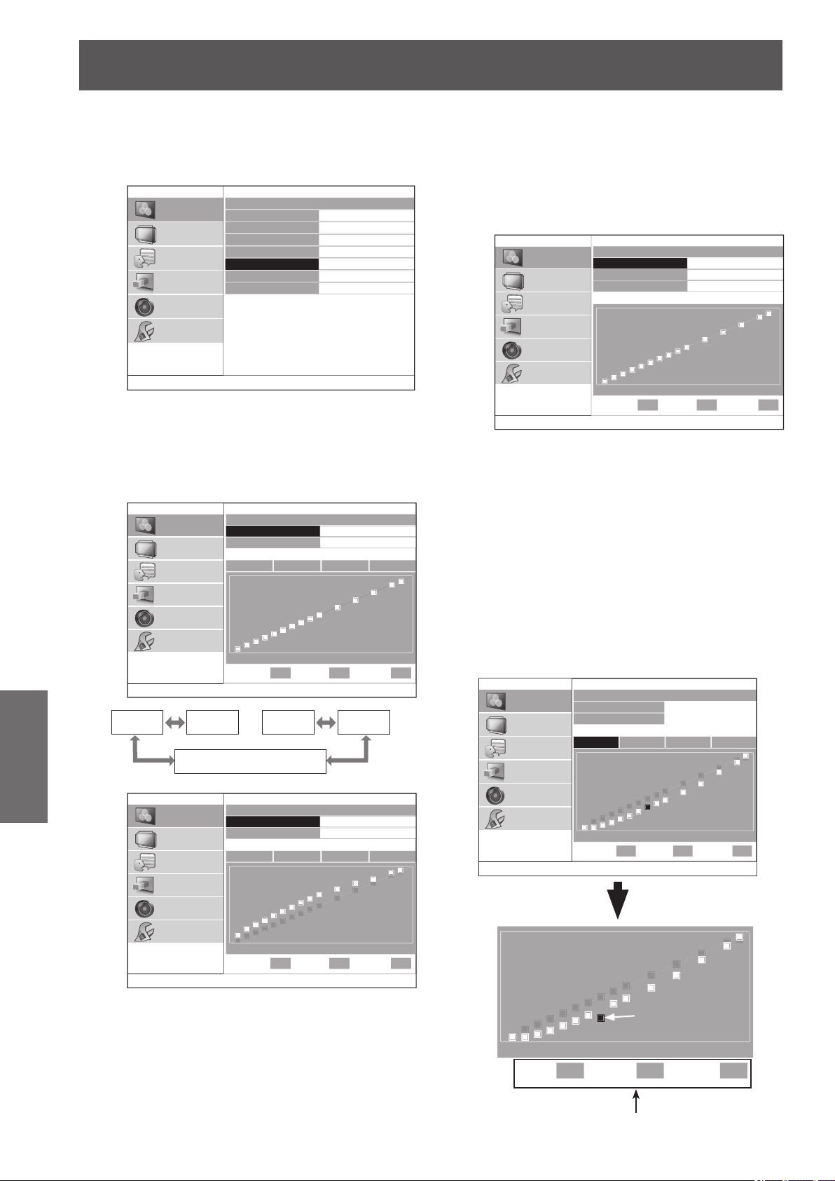
[PICTURE] menu
46 -
ENGLISH
Settings
3) Press the ▲▼ buttons to select [START
ADJUSTMENT], and press the <ENTER>
button.
z
The [ADVANCED ADJUST] menu appears.
GAMMA ADJUSTMENT
ADJUSTMENT MODE
GAMMA HIGH
GAMMA MID
GAMMA LOW
START ADJUSTMENT
GAMMA NAME CHANGE
INITIALIZE
ADVANCED1
PICTURE
POSITION
LANGUAGE
3D SETTINGS
LENS CONTROL
OPTION
4) Press the ▲▼ buttons to select [GAMMA
PRESET], and then press the
◄►
buttons
to change the preset gamma.
z
The value can be adjusted in the range of -0.40
to +0.80 with the current gamma value as the
reference.
ADVANCED ADJUST
GAMMA PRESET
REFERENCE POINTS
0.00
ON
PICTURE
POSITION
LANGUAGE
3D SETTINGS
LENS CONTROL
OPTION
0%
POINT 8
Y R G B
INPUT OUTPUT
50% 100%
40% 0
[-0.40] [-0.35]
・・・
[+0.75] [+0.80]
[R: 0.00 G: 0.00 B: 0.00]
ADVANCED ADJUST
GAMMA PRESET
REFERENCE POINTS
-0.40
ON
PICTURE
POSITION
LANGUAGE
3D SETTINGS
LENS CONTROL
OPTION
0%
POINT 8
Y R G B
INPUT OUTPUT
50% 100%
40% +18
0% 50% 100%
z
If you select [R: 0.00 G: 0.00 B: 0.00] under
[GAMMA PRESET], and then press the <ENTER>
button, the [GAMMA PRESET] menu is displayed.
Press the ▲▼ buttons to select the [R], [G], or [B]
row, and then press the ◄► buttons to change
the preset gamma for each of R, G, and B.
z
The value can be adjusted in the range of -0.40 to
+0.80 with the current gamma value as the reference.
GAMMA PRESET
R
G
B
0.00
0.00
0.00
PICTURE
POSITION
LANGUAGE
3D SETTINGS
LENS CONTROL
OPTION
0%
POINT 8
INPUT OUTPUT
50% 100%
40% 0
5) Press the ▲▼ buttons to select the [Y],
[R], [G], or [B] row, and then press the ◄►
buttons to select any one of [Y], [R], [G], or
[B]. Finally, press the <ENTER> button.
z
The adjustment screen for the selected Y
(intensity) or each of the colors R, G, or B
appears, and gamma can be adjusted up to a
maximum of 15 points.
z
You can switch between [Y], [R], [G], and [B]
each time you press the <ENTER> button.
z
When you adjust the input level or the output
level, the menu is deleted, and an adjustment
screen as shown below appears.
z
To return to the screen displayed in 4), press
the <RETURN> button.
PICTURE
POSITION
LANGUAGE
3D SETTINGS
LENS CONTROL
OPTION
0%
POINT 8
INPUT OUTPUT
50% 100%
40% -16
ADVANCED ADJUST
GAMMA PRESET
REFERENCE POINTS
+0.40
ON
Y R G B
LANGUAGE
3D SETTINGS
LENS CONTROL
OPTION
0%
POINT 8
INPUT OUTPUT
50% 100%
40% -36
The information of the currently selected point
(A) is displayed.
(A)
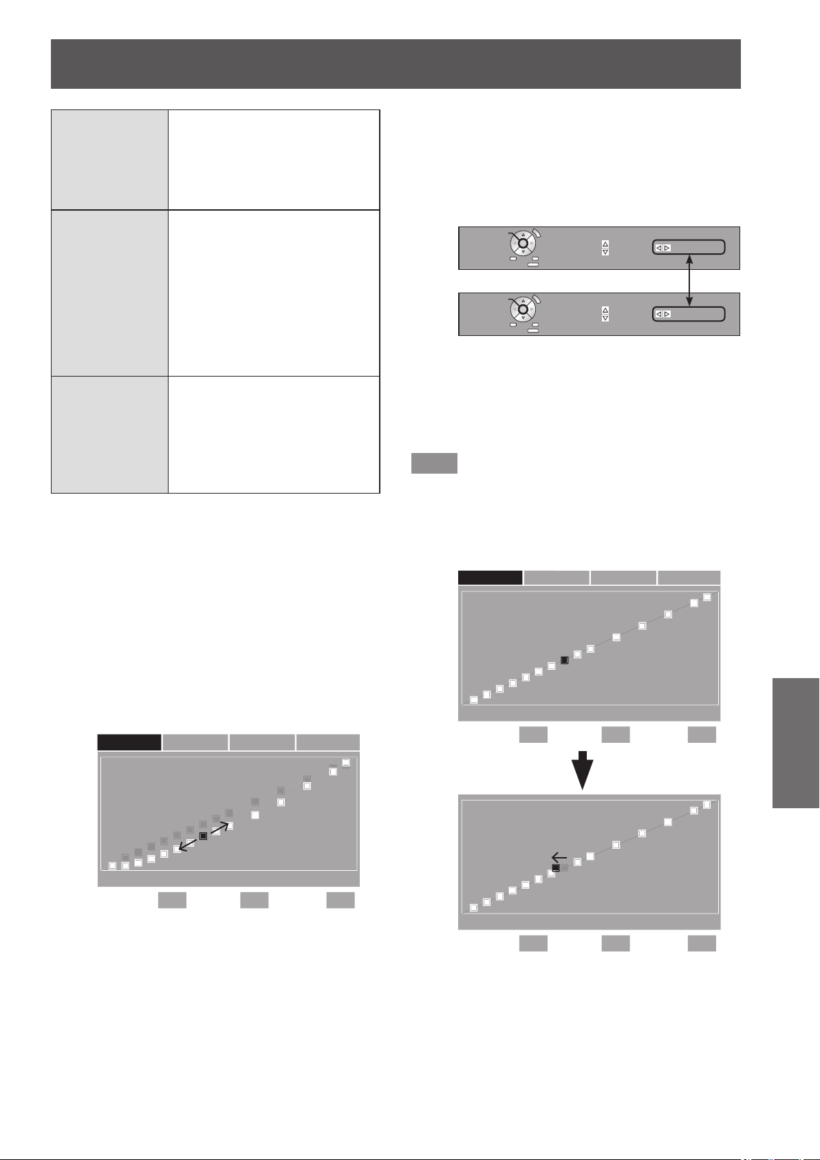
[PICTURE] menu
ENGLISH
- 47
Settings
POINT
Display the currently selected
point number. The number is in
the order of 1 to 15 starting from
the lower input level. The selected
point ashes in yellow on the
adjustment screen.
INPUT
Display the input level of the
currently selected point. Can
be set in the range of 1 to 99%
in increments of 1%. When
dispatching from the factory, the
input level is set in the order of
5%, 10%, 15%, 20%, 25%, 30%,
35%, 40%, 45%, 50%, 60%, 70%,
80%, 90%, and 95% starting from
point 1.
OUTPUT
Display the output level of the
currently selected point. The
difference from the standard value
can be set in the range of -252
to +252. The adjustable range
depends on the input level. The
standard value is 0.
6) Change the POINT, adjust the INPUT level,
and also adjust the OUTPUT level.
z
In the screen displayed in 5), select any one
from [Y], [R], [G], or [B], and then perform the
operation after pressing the <ENTER> button.
The respective operations are described below.
a. Changing the point to be adjusted
z
Press the ◄► buttons to move the cursor for
selecting the point, to the left or right.
Press the
►
button to move one point to the right.
Press the
◄
button to move one point to the left.
POSITION
LANGUAGE
3D SETTINGS
LENS CONTROL
OPTION
0%
POINT 8
INPUT OUTPUT
50% 100%
40% -16
Y R G B
b. Adjusting the input level (only [Y])
z
Press the <SUB MENU> button to set the
[OPERATION MODE] to [INPUT ADJUSTMENT].
See the operation guide to check if the current
status is the [CHANGE POINT] mode or the [INPUT
ADJUSTMENT] mode.
Operation Guide
OPERATION MODE
RESET
(RESET ALL: 3 sec)
OUTPUT ADJ. CHANGE POINT
RETURN
SET AS NEW REF.
CHANNEL
CHANGE
OPERATION MODE
RESET
(RESET ALL: 3 sec)
OUTPUT ADJ. INPUT ADJ.
RETURN
SET AS NEW REF.
CHANNEL
CHANGE
z
If you press the ◄► buttons, you can adjust the
input level of the currently selected point.
The input level can be set in the range of 1 to 99%
in increments of 1%. However, you cannot set an
input level more than that of the adjoining points.
Note
z
The input level can be adjusted only when [Y] is being
adjusted.
The input level cannot be adjusted when [R], [G], or [B]
are being adjusted.
Ex: When the
◄
button is pressed on [Y].
LANGUAGE
3D SETTINGS
LENS CONTROL
OPTION
0%
POINT 8
INPUT OUTPUT
50% 100%
37% +8
LANGUAGE
3D SETTINGS
LENS CONTROL
OPTION
0%
POINT 8
Y R G B
INPUT OUTPUT
50% 100%
40% 0
Move left
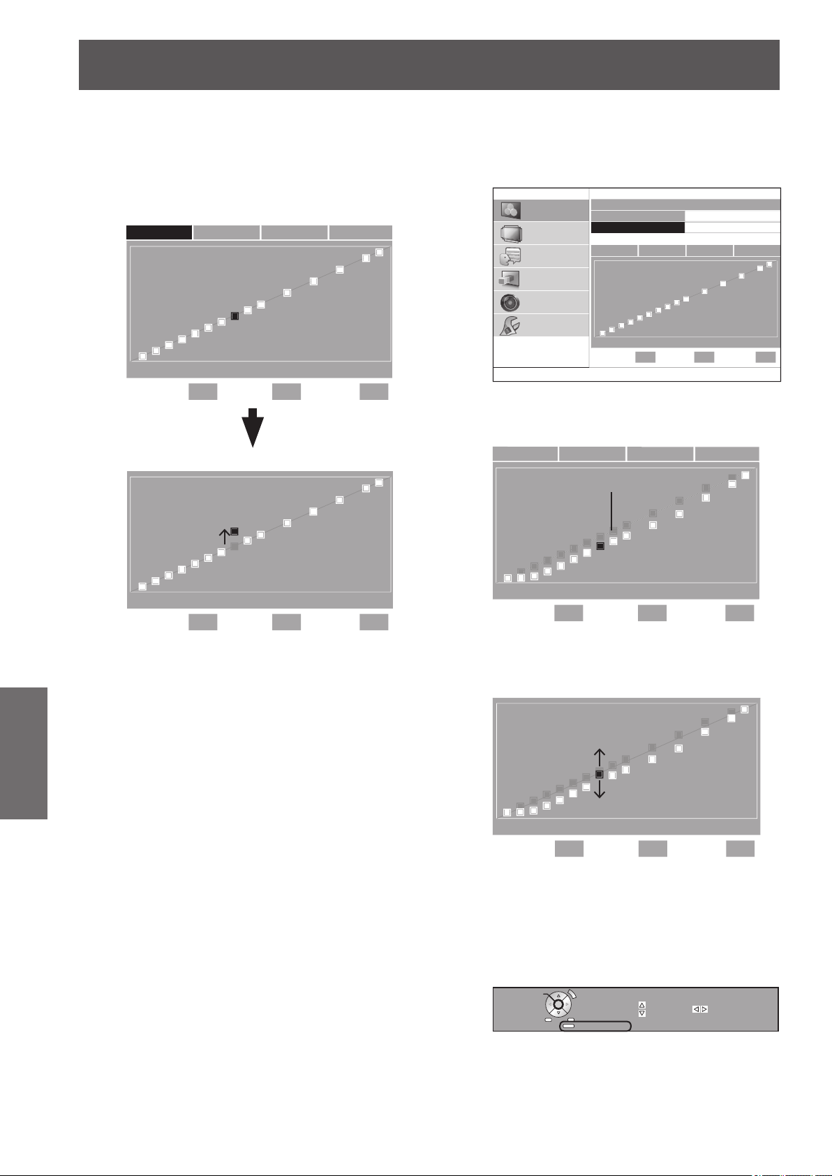
[PICTURE] menu
48 -
ENGLISH
Settings
c. Adjusting the output level
z
If you press the ▲▼ buttons, you can adjust
the output level of the currently selected point.
z
Output level can be adjusted for each color on
the [Y][R][G][B] screen.
Ex: When the ▲ button is pressed on [Y].
LANGUAGE
3D SETTINGS
LENS CONTROL
OPTION
0%
POINT 8
INPUT OUTPUT
50% 100%
40% +30
LANGUAGE
3D SETTINGS
LENS CONTROL
OPTION
0%
POINT 8
Y R G B
INPUT OUTPUT
50% 100%
40% 0
Move above
d. Matching the output level to the reference point
z
In the screen displayed in 4), press the ▲ ▼
buttons to place the cursor on [REFERENCE
POINTS], and then press the ◄► buttons to switch
to [ON].
ADVANCED ADJUST
GAMMA PRESET
REFERENCE POINTS
0.00
ON
PICTURE
POSITION
LANGUAGE
3D SETTINGS
LENS CONTROL
OPTION
0%
POINT 8
Y R G B
INPUT OUTPUT
50% 100%
40% 0
z
If you display the adjustment screen when
[REFERENCE POINTS] is set to [ON], the
reference points are displayed on the screen.
LANGUAGE
3D SETTINGS
LENS CONTROL
OPTION
0%
POINT 8
Y R G B
INPUT OUTPUT
50% 100%
40% -16
Reference points (gray)
z
After selecting any one of [Y], [R], [G], or [B] in the
screen displayed in 5), you can match the output
level of the point selected with the ▲▼ buttons with
the reference point.
LANGUAGE
3D SETTINGS
LENS CONTROL
OPTION
0%
POINT 8
INPUT OUTPUT
50% 100%
40% -6
z
By matching the output level of the currently
selected point with the reference point, the gamma
value can be created by combining two gamma
values, such as by setting [GAMMA PRESET] to
[+0.40] and [+0.30].
z
You can refresh the reference points by pressing
the <FUNCTION> button of the remote control.
OPERATION MODE
RESET
(RESET ALL: 3 sec)
OUTPUT ADJ. INPUT ADJ.
RETURN
SET AS NEW REF.
CHANNEL
CHANGE
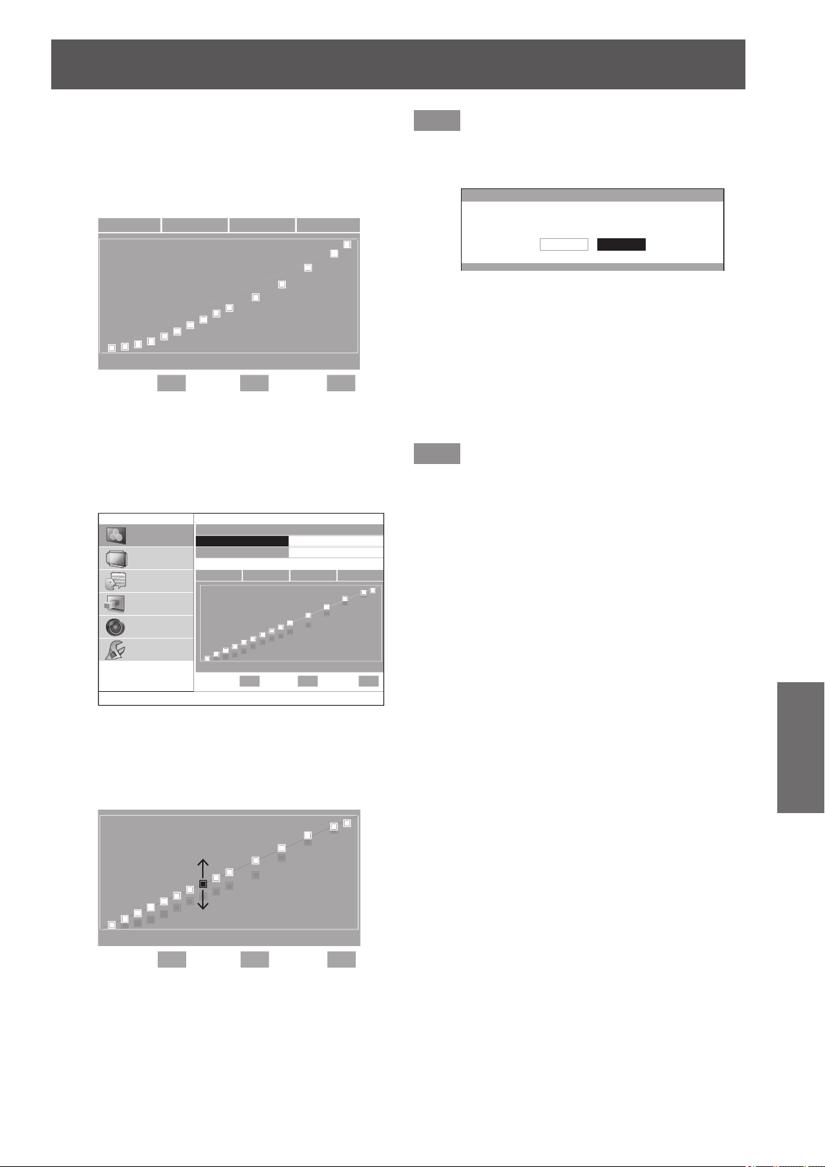
[PICTURE] menu
ENGLISH
- 49
Settings
Example) When the data for gamma preset value
+0.40 and gamma preset value 0.00 is combined
1. Set [GAMMA PRESET] to +0.40, display the
adjustment screen for any one of [Y], [R], [G], and [B],
or then press the <FUNCTION> button to refresh the
reference points.
LANGUAGE
3D SETTINGS
LENS CONTROL
OPTION
0%
POINT 8
Y R G B
INPUT OUTPUT
50% 100%
40% -16
2. Press the <RETURN> button to return to the screen
displayed in 4), and then select [GAMMA PRESET]
with the ▲ ▼ buttons.
3. Set [GAMMA PRESET] to [0.00] with the ◄►
buttons.
ADVANCED ADJUST
GAMMA PRESET
REFERENCE POINTS
0.00
ON
PICTURE
POSITION
LANGUAGE
3D SETTINGS
LENS CONTROL
OPTION
0%
POINT 8
Y R G B
INPUT OUTPUT
50% 100%
40% 0
The reference points refreshed earlier are displayed.
4. Select one of [Y][R][G][B] and press the <ENTER>
button.
5. Adjust the output level with the ▲ ▼ buttons using
the reference points as the standard.
LANGUAGE
3D SETTINGS
LENS CONTROL
OPTION
0%
POINT 8
INPUT OUTPUT
50% 100%
40% 0
Note
z
If you change the output level of the reference point from
the preset value, a conrmation screen is displayed when
changing [GAMMA PRESET].
GAMMA PRESET
IF GAMMA PRESET IS USED.
ADJUSTED CUSTOM CURVE DATA WILL BE DELETED.
CANCELOK
e. Returning the output level to the default setting
z
If you press the <DEFAULT> button while the output
level is being adjusted in c. or d. described on the
previous page, the output level of the currently
selected point returns to the default setting.
z
If you press and hold the <DEFAULT> button for
three seconds or more while the output level is
being adjusted in c. or d. described on the previous
page, the output level of all points returns to the
default setting.
Note
z
The input level does not return to the default setting even
when the <DEFAULT> button is pressed.
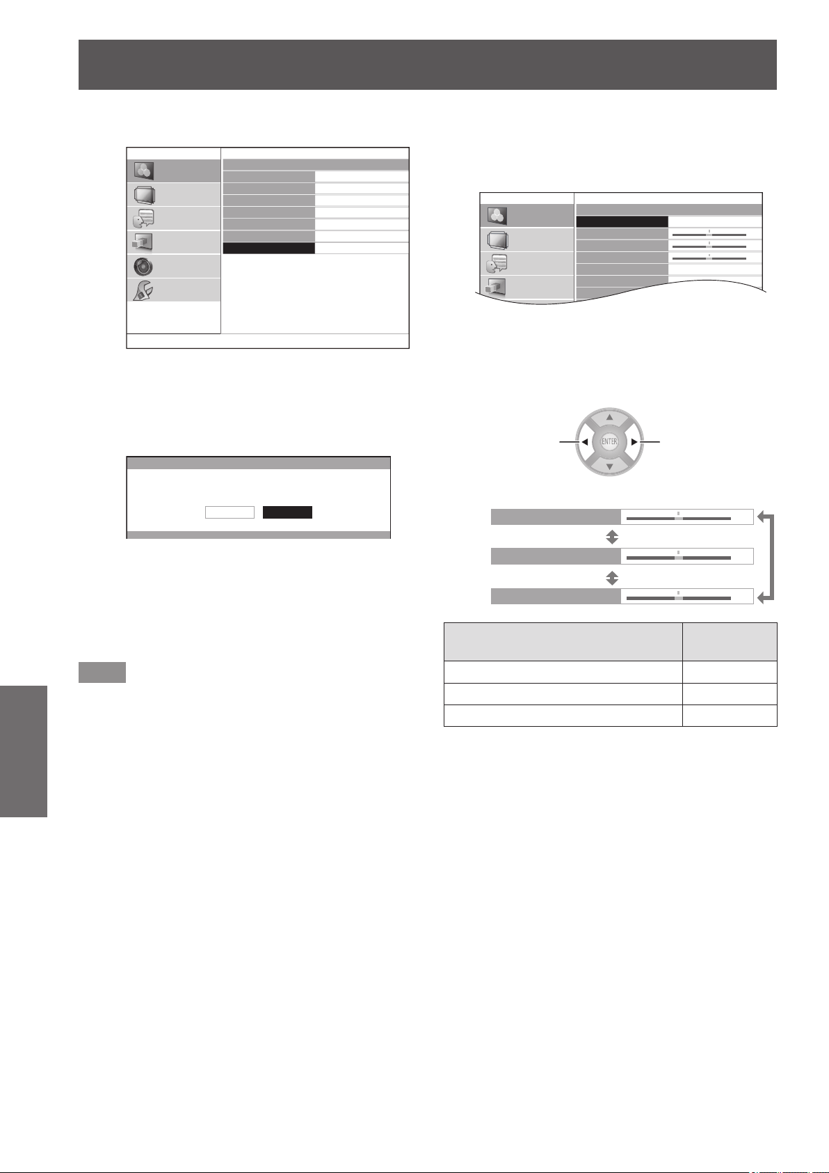
[PICTURE] menu
50 -
ENGLISH
Settings
●
Initialize the gamma adjustment results
GAMMA ADJUSTMENT
ADJUSTMENT MODE
GAMMA HIGH
GAMMA MID
GAMMA LOW
START ADJUSTMENT
GAMMA NAME CHANGE
INITIALIZE
ADVANCED1
PICTURE
POSITION
LANGUAGE
3D SETTINGS
LENS CONTROL
OPTION
1) Press the ▲▼ buttons to select
[INITIALIZE] and press the <ENTER>
button.
z
The conrmation message is displayed for the
gamma initialization.
GAMMA ADJUSTMENT
INITIALIZE GAMMA ADJUSTMENT.
CANCELOK
2) Select [OK] with the
▲
▼
buttons and press
the <ENTER>button.
z
[ADVANCED 1] - [ADVANCED8] are all
set to the factory default setting, and
the [ADJUSTMENT MODE] is set to
[ADVANCED1].
Note
z
Initialization is not available in [SIMPLE] mode.
z
You cannot execute [INITIALIZE] when two screens are
being adjusted.
●
Adjusting the gamma (when [SIMPLE] is
selected for [ADJUSTMENT MODE])
1) Press the ◄► buttons to select [SIMPLE].
GAMMA ADJUSTMENT
ADJUSTMENT MODE
GAMMA HIGH
GAMMA MID
GAMMA LOW
START ADJUSTMENT
GAMMA NAME CHANGE
INITIALIZE
SIMPLE
0
0
0
PICTURE
POSITION
LANGUAGE
3D SETTINGS
2) Select item with the ▲▼ buttons, and
adjust with the
▲
▼
buttons.
z
You can adjust linear intensity at 3 levels (high,
mid, low). Press ▲ ▼ to select your required
gamma levels.
-1
+1
GAMMA HIGH
GAMMA MID
GAMMA LOW
0
0
0
[ADVANCED MENU] menu items
Default
setting
[GAMMA HIGH] 0
[GAMMA MID] 0
[GAMMA LOW] 0
z
Setting range: -8 to +8
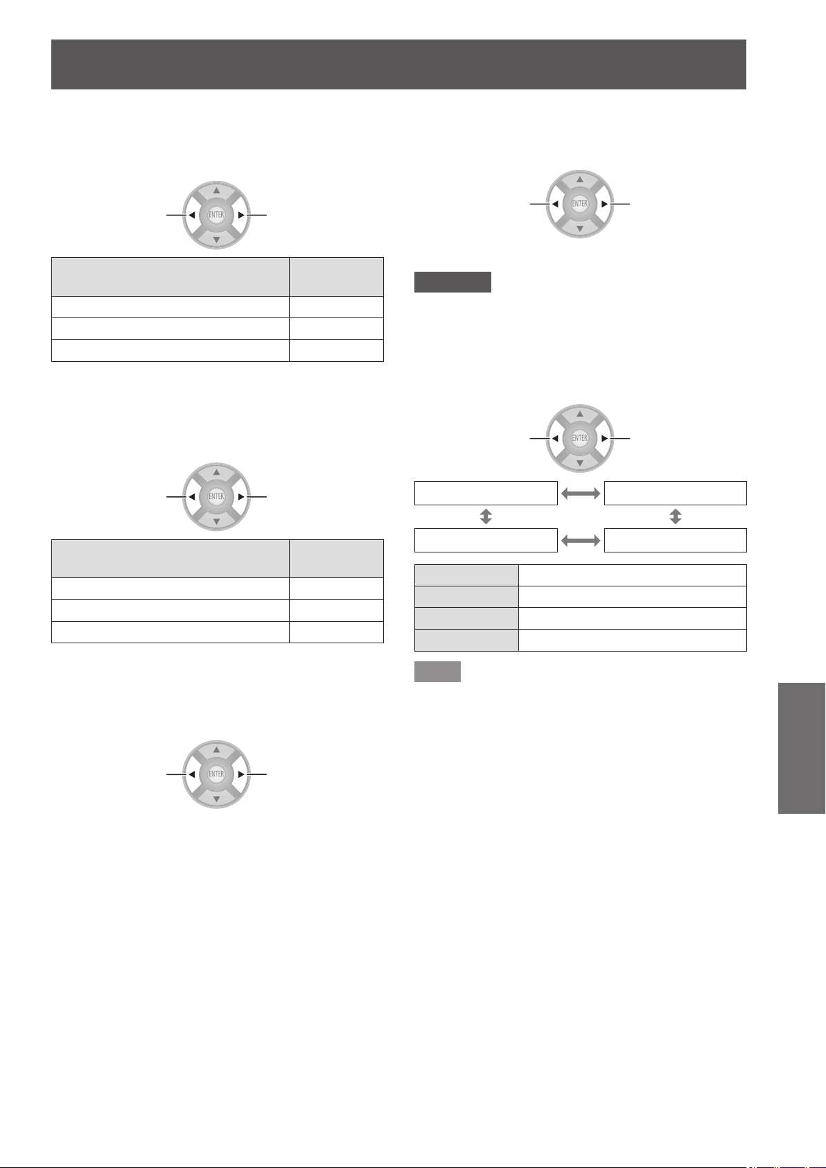
[PICTURE] menu
ENGLISH
- 51
Settings
■
[CONTRAST]
You can adjust color temperatures centering mainly on
white.
R (RED), G (GREEN), B (BLUE)
-1
+1
[ADVANCED MENU] menu items
Default
setting
[CONTRAST R] 0
[CONTRAST G] 0
[CONTRAST B] 0
z
Setting range: -32 to +32
■
[BRIGHTNESS]
You can adjust color temperatures centering mainly on black.
R (RED), G (GREEN), B (BLUE)
-1
+1
[ADVANCED MENU] menu items
Default
setting
[BRIGHTNESS R] 0
[BRIGHTNESS G] 0
[BRIGHTNESS B] 0
z
Setting range: -16 to +16
■
[NR]
You can eliminate the noise that occurs when the input
signal deteriorates.
Weaken
Strengthen
z
Setting range: 0 to +3
■
[MPEG NR]
You can eliminate the noise that occurs upon projection for
videos that use MPEG compression.
Weaken Strengthen
z
Setting range: 0 to +3
Attention
z
Use a strong setting when projecting an MPEG video.
z
COMPUTER (RGB) signal is not supported.
■
[FRAME CREATION]
You can activate the rendering system for fast motion
frames with fewer afterimage.
Switch settings Switch settings
[OFF] [MODE1]
[MODE3] [MODE2]
[OFF] Deactivate
[MODE1] Setting for a standard image
[MODE2] Setting for a theater image
[MODE3] Setting for a fast moving image
Note
z
With some of the images, it might be difcult to see a
difference in result.
z
If [FRAME CREATION] is set to active, video may be
delayed in some cases. In this case, select [OFF].
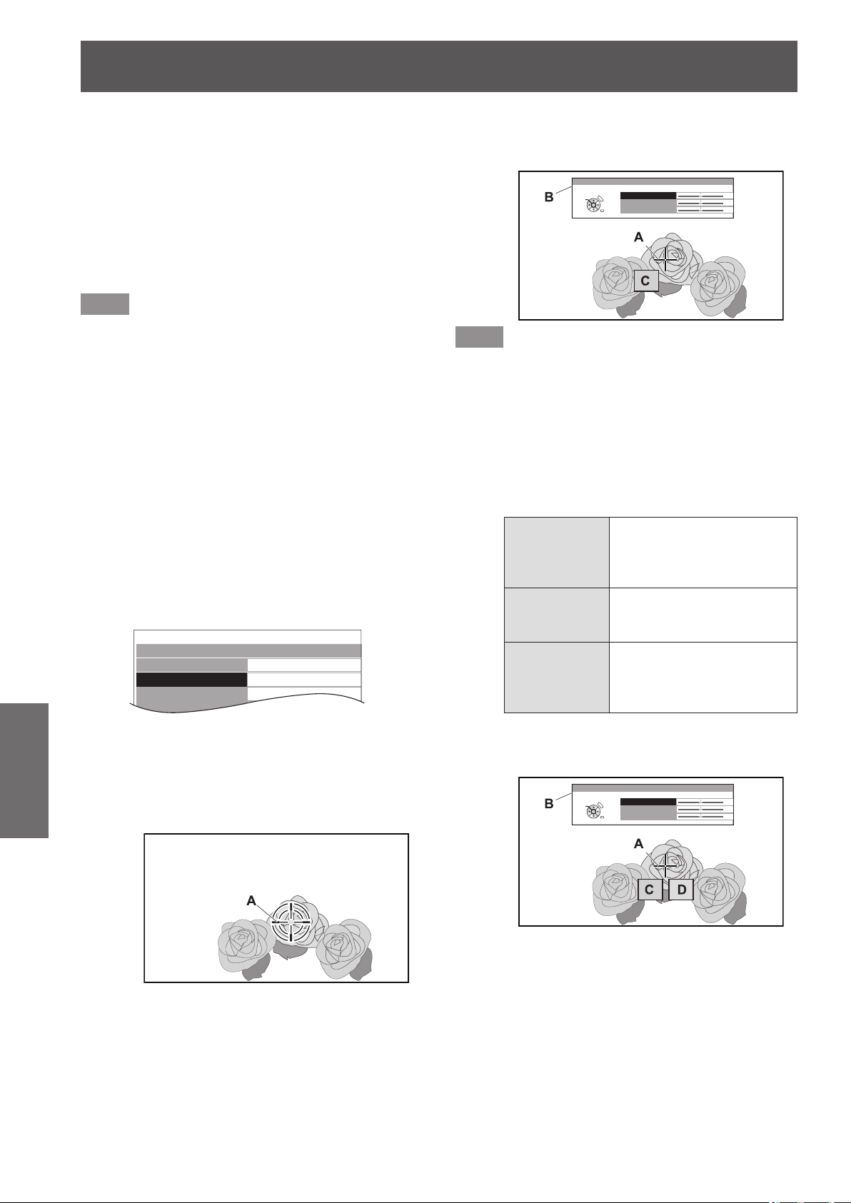
[PICTURE] menu
52 -
ENGLISH
Settings
■
[COLOR MANAGEMENT]
For the selected [PICTURE MODE], you can adjust a
selected color individually with [CURSOR] mode or adjust
the six color components (Red, Green, Blue, Cyan,
Magenta, Yellow) with [RGBCMY] mode.
Adjustment results can be saved as a prole and called
later.
●
Create a new prole
Note
z
When the input signal is switched while adjusting,
adjustment details are not saved.
z
If there is another area, which has the exact same or
similar color as the target on the same screen, these
colors will be adjusted as well.
z
You can adjust all colors except white, gray and black.
z
If you edit a single color to be individual different colors,
the desired color may not be achieved.
z
When you execute [COLOR MANAGEMENT] while a
3D image is being displayed, only the left eye image is
displayed.
z
Adjusting the selected color (when
[CURSOR] is selected for [ADJUSTMENT
MODE])
Select the desired color with a cursor and adjust.
1) Press the ◄► buttons to select [CURSOR]
in [ADJUSTMENT MODE].
COLOR MANAGEMENT
PROFILE
ADJUSTMENT MODE
START ADJUSTMENT
LOG
NORMAL
CURSOR
2) Press the ▲▼ buttons to select [START
ADJUSTMENT] and press the <ENTER>
button.
z
The cross cursor (A) is displayed, and the
projected image is captured.
Screen
3) Move the cursor with the ▲▼◄► buttons
to the required place to select a color.
z
Align the center of the cross cursor on the point
in the projected image to be adjusted.
4) Press the <ENTER> button.
z
[CURSOR] menu (B) and the color selected (C)
are displayed.
COLOR
TINT
BRIGHTNESS
CURSOR
0
0
0
RETURN
DEFAULT
SELECT
ENTER
Screen
Note
z
In some cases you may be unable to adjust when the
very edge point of the projection area is selected.
z
You can create a prole only when [ADJUSTMENT
MODE] is set to either [CURSOR] or [RGBCMY]. A prole
cannot be created from both adjustments.
z
White, gray and black cannot be edited.
5) Press the ▲▼ buttons to select a menu
item and the ◄► buttons to adjust each
item level.
[COLOR]
Adjust the vividness of the
color.
z
Setting range:
−30 to +30
[TINT]
Adjust the color tone.
z
Setting range:
−30 to +30
[BRIGHTNESS]
Adjust the brightness of the
color.
z
Setting range:
−20 to +20
z
The default setting for each item is [0].
After adjusting, the post-adjustment color (D) is
displayed.
COLOR
TINT
BRIGHTNESS
CURSOR
RETURN
DEFAULT
SELECT
ENTER
0
0
0
Screen
6) Press the <ENTER> button.
z
[PROCESSING] message is displayed for a few
seconds and the result is stored in [LOG].
You can store up to 8 logs under [LOG]. Press
the <RETURN> or <MENU> button to return
to the previous menu. Repeat from step 3) to
store more adjustments.
7) Press the <RETURN> button or <MENU>
button twice.
z
This returns you to the [COLOR
MANAGEMENT] menu.
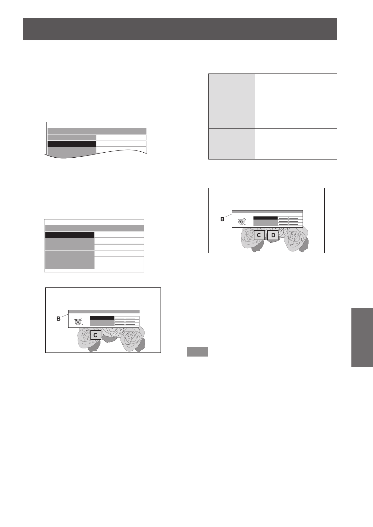
[PICTURE] menu
ENGLISH
- 53
Settings
z
Adjusting the selected color (when
[RGBCMY] is selected for [ADJUSTMENT
MODE])
Select the color from 6 different color types ([RED],
[GREEN], [BLUE], [CYAN], [MAGENTA], [YELLOW]) and
adjust [COLOR], [TINT] and [BRIGHTNESS].
1) Press the ◄► buttons to select [RGBCMY]
in [ADJUSTMENT MODE].
COLOR MANAGEMENT
PROFILE
ADJUSTMENT MODE
START ADJUSTMENT
LOG
NORMAL
RGBCMY
2) Press the ▲▼ buttons to select [START
ADJUSTMENT] and press the <ENTER>
button.
3) Press the ▲▼ buttons to select your
desired color and press the <ENTER>
button.
RGBCMY ADJUSTMENT
RED
GREEN
BLUE
CYAN
MAGENTA
YELLOW
z
Menu (B) and the base color (C) is displayed.
COLOR
TINT
BRIGHTNESS
RED
0
0
0
RETURN
DEFAULT
SELECT
ENTER
Screen
4) Press the ▲▼ buttons to select a menu
item and the ◄► buttons to adjust each
item level.
[COLOR]
Adjust the vividness of the
color.
z
Setting range:
−30 to +30
[TINT]
Adjust the color tone.
z
Setting range:
−30 to +30
[BRIGHTNESS]
Adjust the brightness of the
color.
z
Setting range:
−20 to +20
z
The default setting for each item is [0].
After adjusting, the post-adjustment color (D) is
displayed.
COLOR
TINT
BRIGHTNESS
RED
0
0
0
RETURN
DEFAULT
SELECT
ENTER
Screen
5) Press the <ENTER> button.
z
[PROCESSING] message is displayed for a few
seconds and the result is stored in [LOG].
You can store up to 6 different color adjusted
images under [LOG]. Press the <RETURN>
button to adjust the other colors. Repeat from
step 3) to store more adjustments.
6) Press the <RETURN> button or <MENU>
button twice.
z
This returns you to the [COLOR
MANAGEMENT] menu.
Note
z
Base color (C) and post-adjustment color (D) (displayed
when [ADJUSTMENT MODE] is set to [RGBCMY]), are
intended to be guide colors only.
●
Editing/deleting logs
You can edit or delete stored logs.
Press the ▲▼ buttons to select [LOG] and
press the <ENTER> button.
z
The [LOG] menu is displayed.
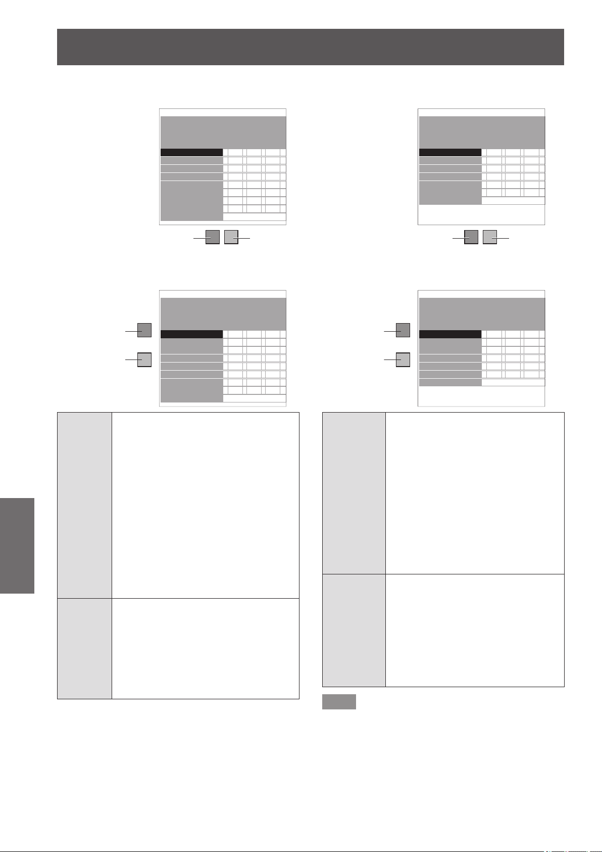
[PICTURE] menu
54 -
ENGLISH
Settings
z
Managing the stored logs created through the
[CURSOR] mode
LOG
ADJUSTMENT MODE
PICTURE MODE
POINT1
POINT2
POINT3
POINT4
POINT5
POINT6
POINT7
POINT8
ALL DELETE
: CURSOR
: NORMAL
COLOR TINT BRIGHTNESS
+10 +10 +10
+10 +10 +10
+10 +10 +10
+10 +10 +10
+10 +10 +10
+10 +10 +10
+10 +10 +10
+10 +10 +10
Adjusted
color
Selected
color
The below display appears only when 720/60p Frame
Packing and 720/50p Frame Packing 3D images are being
displayed.
LOG
ADJUSTMENT MODE
PICTURE MODE
POINT1
POINT2
POINT3
POINT4
POINT5
POINT6
POINT7
POINT8
ALL DELETE
: CURSOR
: NORMAL
COLOR TINT BRIGHTNESS
+10 +10 +10
+10 +10 +10
+10 +10 +10
+10 +10 +10
+10 +10 +10
+10 +10 +10
+10 +10 +10
+10 +10 +10
Adjusted
color
Selected
color
[POINT]
[1] - [8]
Press ▲ ▼ to select the point you wish
to edit, and press the <ENTER> button
to display the screen to select [CHANGE]
or [DELETE].
[CHANGE]: The [CURSOR] menu is
displayed and you can
readjust the color.
[DELETE]: Deletes point adjustment
data.
Press the <ENTER> button
to display a conrmation
message.
Select [OK] with the
▲
▼
buttons and press the
<ENTER> button to delete.
[ALL
DELETE]
When [ALL DELETE] is selected using
the ▲▼ buttons and <ENTER> is
pressed, a conrmation message is
displayed.
Select [OK] with the
▲
▼
buttons and press
the <ENTER> button to delete all logs.
The [PROFILE] setting will be set to
[NORMAL] if all logs are deleted.
z
Managing the stored logs created through the
[RGBCMY] mode
LOG
ADJUSTMENT MODE
PICTURE MODE
RED
GREEN
BLUE
CYAN
MAGENTA
YELLOW
ALL DELETE
: RGBCMY
: NORMAL
COLOR TINT BRIGHTNESS
+10 +10 +10
+10 +10 +10
+10 +10 +10
+10 +10 +10
+10 +10 +10
+10 +10 +10
Adjusted
color
Selected
color
The below display appears only when 720/60p Frame
Packing and 720/50p Frame Packing 3D images are being
displayed.
LOG
ADJUSTMENT MODE
PICTURE MODE
RED
GREEN
BLUE
CYAN
MAGENTA
YELLOW
ALL DELETE
: RGBCMY
: NORMAL
COLOR TINT BRIGHTNESS
+10 +10 +10
+10 +10 +10
+10 +10 +10
+10 +10 +10
+10 +10 +10
+10 +10 +10
Adjusted
color
Selected
color
[RED]
[GREEN]
[BLUE]
[CYAN]
[MAGENTA]
[YELLOW]
Press ▲ ▼ to select the color you
wish to edit, and press the <ENTER>
button to display the screen to select
[CHANGE] or [DELETE].
[CHANGE]: You can readjust the color.
[DELETE]: Deletes color adjustment
history.
Press the <ENTER> button
to display a conrmation
message.
Select [OK] with the
▲
▼
buttons and press the
<ENTER> button to delete.
[ALL DELETE]
When [ALL DELETE] is selected using
the ▲▼ buttons and <ENTER> is
pressed, a conrmation message is
displayed.
Select [OK] with the
▲
▼
buttons and
press the <ENTER> button to delete
all logs.
The [PROFILE] setting will be set to
[NORMAL] if all logs are deleted.
Note
z
If [ADJUSTMENT MODE] is set to [RGBCMY], adjusting
and registering the [COLOR], [TINT], and [BRIGHTNESS]
as [0] for adjustment values that have been previously
registered deletes them from the log.
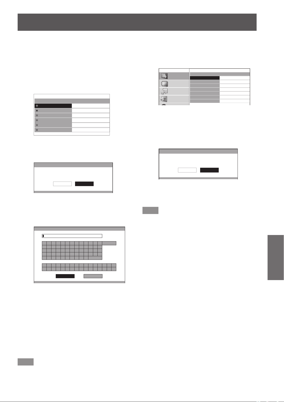
[PICTURE] menu
ENGLISH
- 55
Settings
●
Saving a log setting as a prole
Save a log setting as a prole.
You can save up to six proles.
1) Press the ▲▼ buttons to select [PROFILE
SAVE] and press the <ENTER> button.
z
The [PROFILE SAVE] menu is displayed.
2) Press the ▲▼ buttons to select the number
to be saved and press the <ENTER> button.
PROFILE SAVE
USER1
USER2
USER3
USER4
USER5
USER6
★
: When a prole is already saved
☆
: Not saved
z
The [PROFILE SAVE] conrmation message is
displayed.
PROFILE SAVE
SAVE THE PROFILE DATA AS USER 1.
CANCELOK
3) Select [OK] with the ◄► buttons.
4) Press the <ENTER> button.
z
The [PROFILE NAME INPUT] screen is
displayed.
PROFILE NAME INPUT
A B C D E F G H I J K L M
N O P Q R S T U V W X Y Z
a b c d e f g h i j k l m
n o p q r s t u v w x y z
1 2 3 4 5 6 7 8 9 0
! " # $ % & '
* + - / = ? @ \ ^
_ ` |
~
( ) < > [ ] { } , . : ;
ALL DELETE
SPACE
OK CANCEL
5) Press the ▲▼◄► buttons to select the
characters and press the <ENTER> button
for input.
z
You can enter up to 14 characters.
z
Select [ALL DELETE] and press the <ENTER>
button to erase all input text. If you press the
<DEFAULT> button on the remote control, you can
erase the character currently selected by the cursor
in the input box.
6) Select [OK] with the ▲▼◄► buttons.
7) Press the <ENTER> button.
Note
z
Press the <ENTER> button without entering any text
to keep the default name ([USER1] - [USER6]).
●
Deleting a prole
1) Press the ▲▼ buttons to select [PROFILE
DELETE] and press the <ENTER> button.
z
The [PROFILE DELETE] menu is displayed.
PROFILE DELETE
USER1
USER2
USER3
USER4
USER5
USER6
ALL DELETE
PICTURE
POSITION
LANGUAGE
3D SETTINGS
2) Press the ▲▼ buttons to select the prole
to be deleted and press the <ENTER>
button.
z
Select [ALL DELETE] to delete all proles.
z
The [PROFILE DELETE] conrmation message
is displayed.
PROFILE DELETE
DELETE THE USER 1 DATA.
CANCELOK
3) Select [OK] with the
▲
▼
buttons.
4) Press the <ENTER> button.
Note
z
If all proles are deleted, the system returns to the
[COLOR MANAGEMENT] menu.
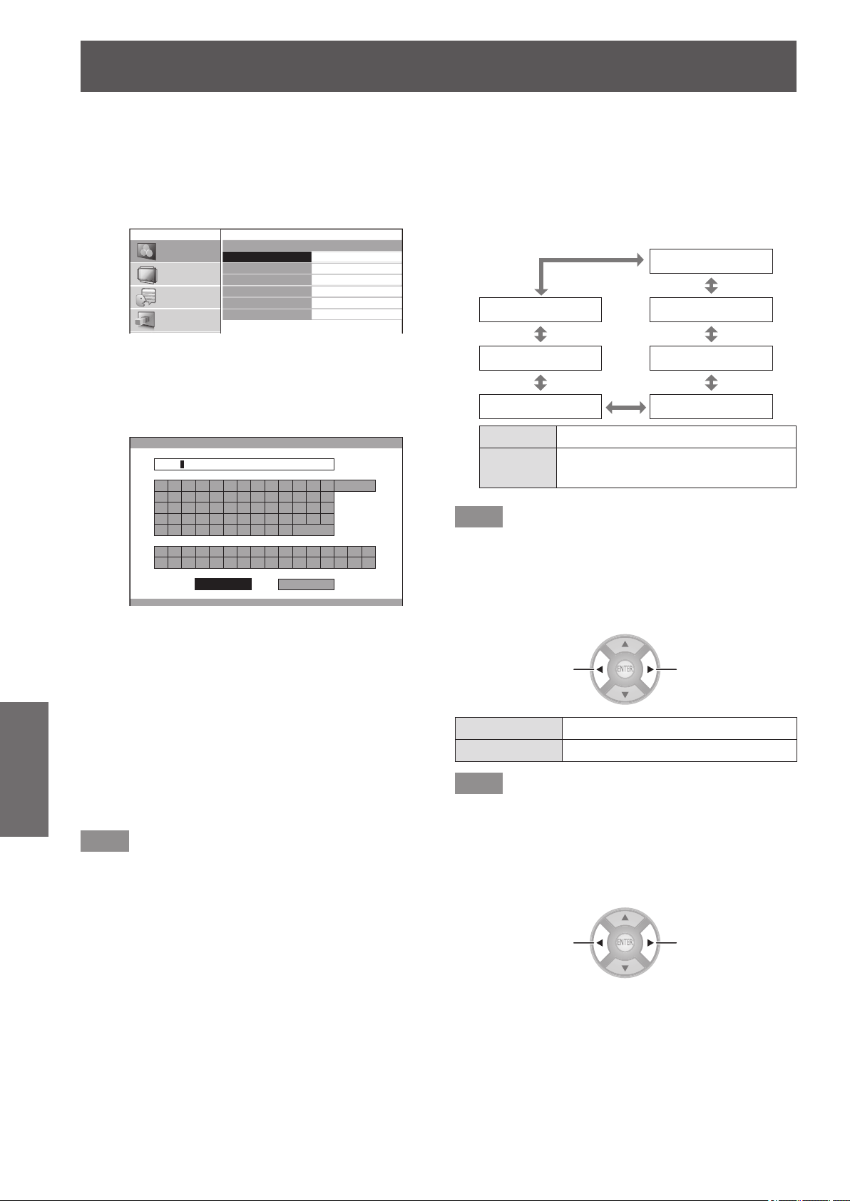
[PICTURE] menu
56 -
ENGLISH
Settings
●
Changing a prole name
1) Press the ▲▼ buttons to select [PROFILE
NAME CHANGE] and press the <ENTER>
button.
z
The [PROFILE NAME CHANGE] menu is
displayed.
PICTURE
POSITION
LANGUAGE
3D SETTINGS
PROFILE NAME CHANGE
USER1
USER2
USER3
USER4
USER5
USER6
2) Press the ▲▼ buttons to select the
prole name to be changed and press the
<ENTER> button.
z
The [PROFILE NAME INPUT] screen is
displayed.
PROFILE NAME INPUT
A B C D E F G H I J K L M
N O P Q R S T U V W X Y Z
a b c d e f g h i j k l m
n o p q r s t u v w x y z
1 2 3 4 5 6 7 8 9 0
! " # $ % & ' * + - / = ? @ \ ^
_ ` |
~
( ) < > [ ] { } , . : ;
ALL DELETE
SPACE
OK CANCEL
SCENE1
3) Press the ▲▼◄► buttons to specify the
location of the required character and
press the <ENTER> button.
z
You can enter up to 14 characters.
z
Select [ALL DELETE] and press the <ENTER>
button to erase all input text. If you press the
<DEFAULT> button on the remote control, you
can erase the character currently selected by
the cursor in the input box.
4) Press the ▲▼◄► buttons to select [OK].
5) Press the <ENTER> button.
Note
z
Press the <ENTER> button without entering any text to
keep the default name ([USER1] - [USER6]).
●
Loading saved proles
Select a saved prole (color adjustment result). The
adjustment values set in the prole are applied to the
[PICTURE MODE] menu and recorded.
1) Press the ▲▼ buttons to select [PROFILE].
2) Use the
▲
▼
buttons to switch the prole.
[USER1]
[NORMAL] [USER2]
[USER6] [USER3]
[USER5] [USER4]
[NORMAL]
Default setting.
[USER1] -
[USER6]
Displayed when prole is saved.
Note
z
Proles that are not saved are not displayed as selection
options.
■
[x.v.Color]
You can switch on/off the automatic adjustment system for
signals which comply with HDMI standard (x.v.Ycc).
Switch settings Switch settings
[ON] Active
[OFF] Inactive
Note
z
This function is only available when a signal supporting
HDMI standards (x.v.Ycc) is input via an HDMI input
terminal and [PICTURE MODE] is set to [REC709].
■
[DETAIL CLARITY]
You can adjust the detail clarity system levels.
Reduce the
effect
Strengthen the
effect
z
Setting range: 0 to +7
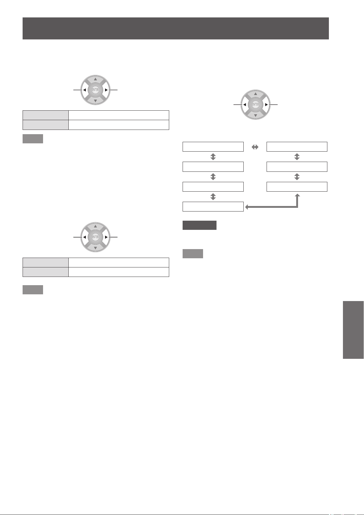
[PICTURE] menu
ENGLISH
- 57
Settings
■
[CINEMA REALITY]
You can switch the automatic image synchronizer on/off for
24 frames a second images, such as movies.
Switch settings Switch settings
[ON] Cinema reality active
[OFF] Cinema reality inactive
Note
z
[CINEMA REALITY] is effective only with interlace
signals.
■
[SUPER WHITE]
Intensity information for higher than 100% intensity that
is included in the image information is replicated. When it
appears that bright whites, such as the clouds or a white
T-shirt at a beach in the middle of the summer, are blurred
out without any contrast, set this function to [ON] to prevent
white peak.
Switch settings Switch settings
[ON] Super white enabled.
[OFF] Super white disabled.
Note
z
This function is disabled under the following conditions:
- When [SPLIT ADJUST] is used for adjustment
- For other than HDMI1, HDMI2, and HDMI3 input
- When the [HDMI SIGNAL LEVEL] is set to [EXPAND]
■
[TV-SYSTEM]
[Only during VIDEO or S-VIDEO signal input]
The projector automatically detects the input signal but if
an unstable signal is input, set the system manually. Set
with a system format that matches the input signal.
Switch settings Switch settings
The settings change as follows each time the button
is pressed.
[AUTO] [NTSC]
[SECAM] [NTSC4.43]
[PAL-N] [PAL]
[PAL-M]
Attention
z
Set this to [AUTO] under normal conditions.
z
Switch the settings to the respective TV signal formats.
Note
z
Setting [AUTO] will automatically select NTSC,
NTSC4.43, PAL, PAL-M, PAL-N, SECAM, or PAL60.
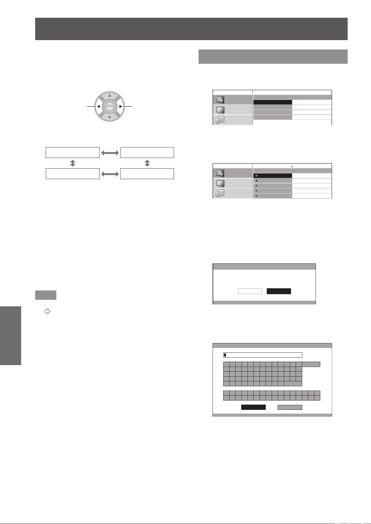
[PICTURE] menu
58 -
ENGLISH
Settings
■
[RGB/YC
B
C
R
]
,
[RGB/YP
B
P
R
]
Set this to [AUTO] under normal conditions. If images are
not displayed correctly when this is set to [AUTO], set
either [RGB] or [YC
B
C
R
], [YP
B
P
R
] in accordance with the
input signal.
Switch settings Switch settings
The settings change as follows each time the button
is pressed.
[AUTO] [RGB]
[YP
B
P
R
] [YC
B
C
R
]
●
When using COMPUTER input
z
When using 480i, 480p, 576i, 576p, or VGA60 input:
Select from [AUTO], [RGB], [YC
B
C
R
].
z
When using a movie based signal input other than
described above:
Select from [AUTO], [RGB], [YP
B
P
R
].
●
When using an HDMI 1/2/3 input
z
When using a 480p or 576p input:
Select from [AUTO], [RGB], [YC
B
C
R
].
z
When using a movie based signal input other than
described above:
Select from [AUTO], [RGB], [YP
B
P
R
].
Note
z
See “List of compatible signals” for signal details.
(
page 100)
z
In some cases the projector may not operate correctly
with some connected devices.
z
These cannot be selected using COMPONENT input
terminals.
[PICTURE MEMORY]
Press the <ENTER> button.
z
The [PICTURE MEMORY] menu is displayed.
PICTURE MEMORY
MEMORY SAVE
MEMORY LOAD
MEMORY DELETE
MEMORY NAME CHANGE
PICTURE
POSITION
LANGUAGE
■
[MEMORY SAVE]
Values set (adjustment values) for videos can be
saved as favorites.
MEMORY SAVE
MEMORY1
MEMORY2
MEMORY3
MEMORY4
MEMORY5
MEMORY6
PICTURE
POSITION
LANGUAGE
1/2
★
: Memory with data already stored
☆
: No data stored
1) Press the ▲▼ buttons to select the
number to be saved and press the
<ENTER> button.
z
The [MEMORY SAVE] conrmation message is
displayed.
MEMORY SAVE
SAVE THE ADJUSTED VALUE AS MEMORY 1.
CANCELOK
2) Select [OK] with the
▲
▼
buttons.
3) Press the <ENTER> button.
z
[MEMORY NAME INPUT] screen is displayed.
MEMORY NAME INPUT
A B C D E F G H I J K L M
N O P Q R S T U V W X Y Z
a b c d e f g h i j k l m
n o p q r s t u v w x y z
1 2 3 4 5 6 7 8 9 0
! " # $ % & '
* + - / = ? @ \ ^
_ ` |
~
( ) < > [ ] { } , . : ;
ALL DELETE
SPACE
OK CANCEL
4) Press the ▲▼◄► buttons to specify the
location of the required character and
press the <ENTER> button.
z
You can enter up to 16 characters.
z
Select [ALL DELETE] and press the <ENTER>
button to erase all input text. If you press the
<DEFAULT> button on the remote control, you can
erase the character currently selected by the cursor
in the input box.
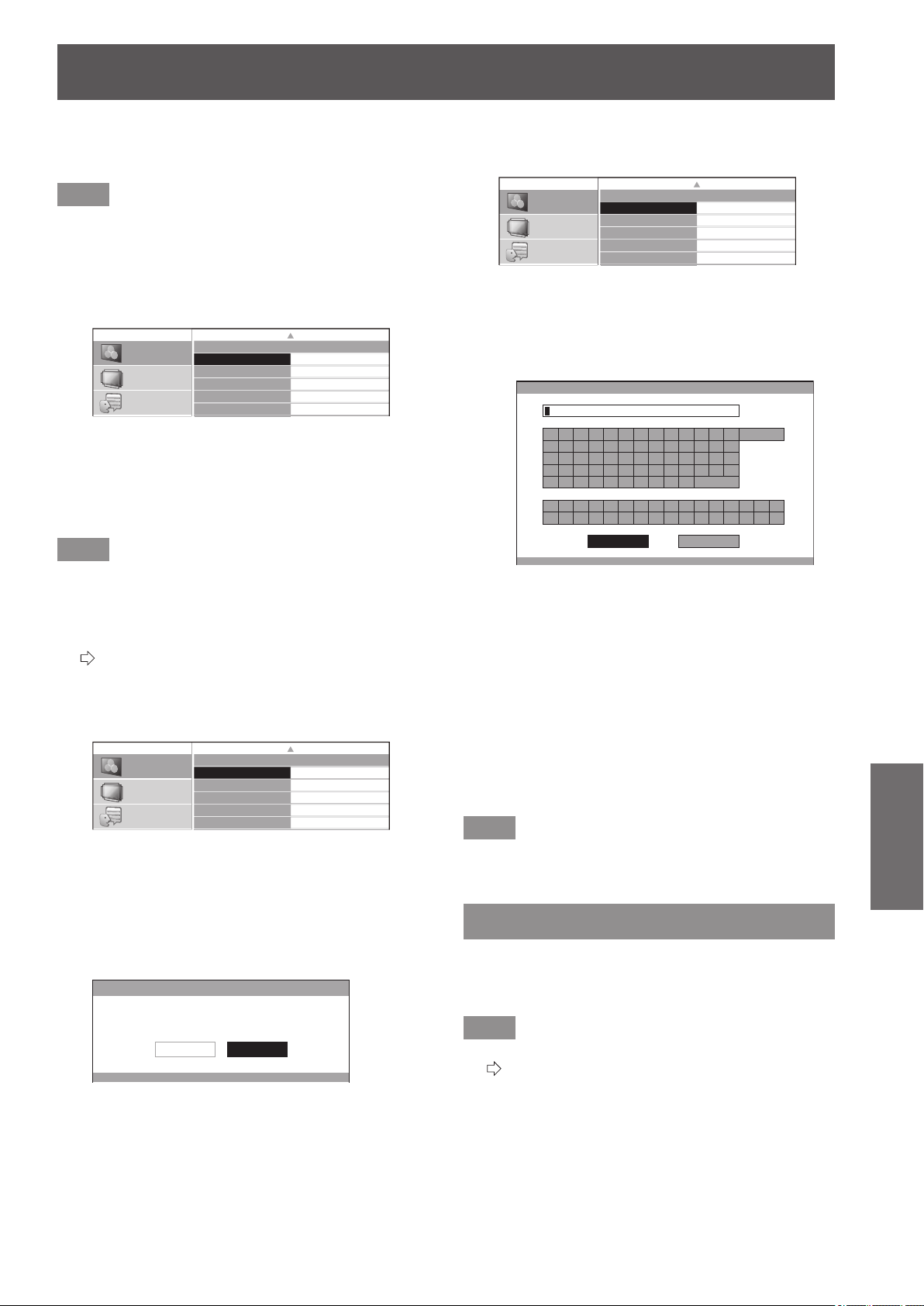
[PICTURE] menu
ENGLISH
- 59
Settings
5) Press the ▲▼◄► buttons to select [OK].
6) Press the <ENTER> button.
Note
z
Press the <ENTER> button without entering any text to
keep the default name ([MEMORY1-16]).
■
[MEMORY LOAD]
You can access the details saved through [MEMORY
SAVE].
MEMORY LOAD
MEMORY1
MEMORY2
MEMORY3
MEMORY4
MEMORY5
MEMORY6
PICTURE
POSITION
LANGUAGE
1/2
1) Press the ▲▼ buttons to select the
memory name to be called.
2) Press the <ENTER> button.
z
The video adjustments for the recalled memory
name are switched to.
Note
z
If there is no saved setting in the [MEMORY SAVE] or
[ALL DELETE] has been performed, the [MEMORY
LOAD] menu will not be selectable.
z
For details how to access with the remote control, see
“Loading a saved setting” in “Remote control operation”.
(
page 33)
■
[MEMORY DELETE]
You can delete memory entries.
MEMORY DELETE
MEMORY1
MEMORY2
MEMORY3
MEMORY4
MEMORY5
MEMORY6
1/2
PICTURE
POSITION
LANGUAGE
1) Press the ▲▼ buttons and select the
memory name to be deleted.
2) Press the <ENTER> button.
z
Select [ALL DELETE] to delete all memory entries.
z
[MEMORY DELETE] conrmation message is
displayed.
MEMORY DELETE
DELETE THE MEMORY 1 DATA.
CANCELOK
3) Select [OK] with the ◄ ► buttons.
4) Press the <ENTER> button.
■
[MEMORY NAME CHANGE]
You can edit the memory name settings.
MEMORY NAME CHANGE
MEMORY1
MEMORY2
MEMORY3
MEMORY4
MEMORY5
MEMORY6
1/2
PICTURE
POSITION
LANGUAGE
1) Press the ▲▼ buttons and select the
memory name to be changed.
2) Press the <ENTER> button.
z
The [MEMORY NAME INPUT] screen is displayed.
MEMORY NAME INPUT
A B C D E F G H I J K L M
N O P Q R S T U V W X Y Z
a b c d e f g h i j k l m
n o p q r s t u v w x y z
1 2 3 4 5 6 7 8 9 0
! " # $ % & ' * + - / = ? @ \ ^
_ ` |
~
( ) < > [ ] { } , . : ;
ALL DELETE
SPACE
OK CANCEL
3) Press the ▲▼◄► buttons to specify
the location of the required character to
enter and press the <ENTER> button.
z
You can enter up to 16 characters.
z
Select [ALL DELETE] and press the <ENTER>
button to erase all input text. If you press the
<DEFAULT> button on the remote control, you can
erase the character currently selected by the cursor
in the input box.
4) Press the ▲▼◄► buttons to select [OK].
5) Press the <ENTER> button.
Note
z
Press the <ENTER> button without entering any text to
keep the default name ([MEMORY1-16]).
SIGNAL MODE
(Available with signals from COMPUTER IN/
COMPONENT IN/HDMI IN only.)
The name of the signal being projected is displayed.
Note
z
See “List of compatible signals” for signal details.
(
page 100)
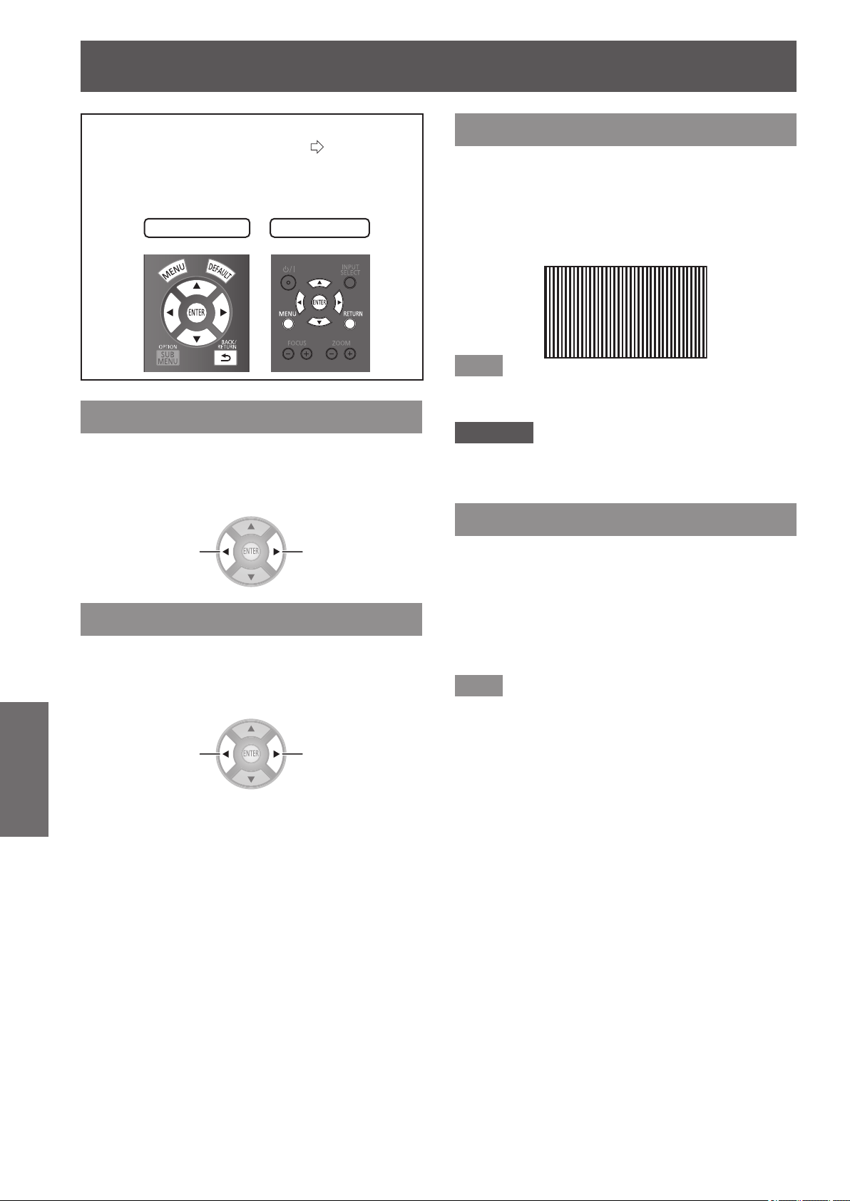
[POSITION] menu
60 -
ENGLISH
Settings
[POSITION] menu
Select [POSITION] from the main menu in
“Navigating through the menu” (
page 37) and
choose an item from the submenu.
z
After selecting an item, use the
▲
▼
to adjust the
screen position.
Remote control
Projector controls
[H-POSITION]
If the position of the picture projected on the screen
deviates when the relative position of the projector
and the screen is correctly set, move the picture
position horizontally.
Moving left
Moving right
[V-POSITION]
If the position of the picture projected on the screen
deviates when the relative position of the projector
and the screen is correctly set, move the picture
position vertically.
Moving
downward
Moving upward
[DOT CLOCK]
This reduces noise that occurs when projecting
striped patterns.
When the kind of striped pattern shown below is
projected, periodic noise sometimes occurs. In such
cases, use the
▲
▼
buttons to adjust to the setting with
the least noise.
Note
z
Clock adjustment is feasible for COMPUTER (RGB)
signal input other than 480i, 576i, 480p, and 576p.
Attention
z
[DOT CLOCK] needs to be adjusted before adjusting the
[CLOCK PHASE].
[CLOCK PHASE]
[Available with signals from COMPUTER IN/
COMPONENT IN only]
If ickering of the image or bleeding of contours
occurs, make adjustments to ensure the optimum
image display.
Use the ◄ ► buttons to adjust noise so that it is not
prominent.
Note
z
If the projecting signal’s dot clock frequency is higher
than 154 MHz, adjusting [DOT CLOCK] or [CLOCK
PHASE] may not eliminate noise.
z
[CLOCK PHASE] cannot be adjusted when a 480i or 576i
COMPONENT (YC
B
C
R
) signal is input.
z
[CLOCK PHASE] cannot be adjusted when a 480i or 576i
COMPUTER (RGB) signal is input.
z
When using digital signal input, adjustment is not
feasible.
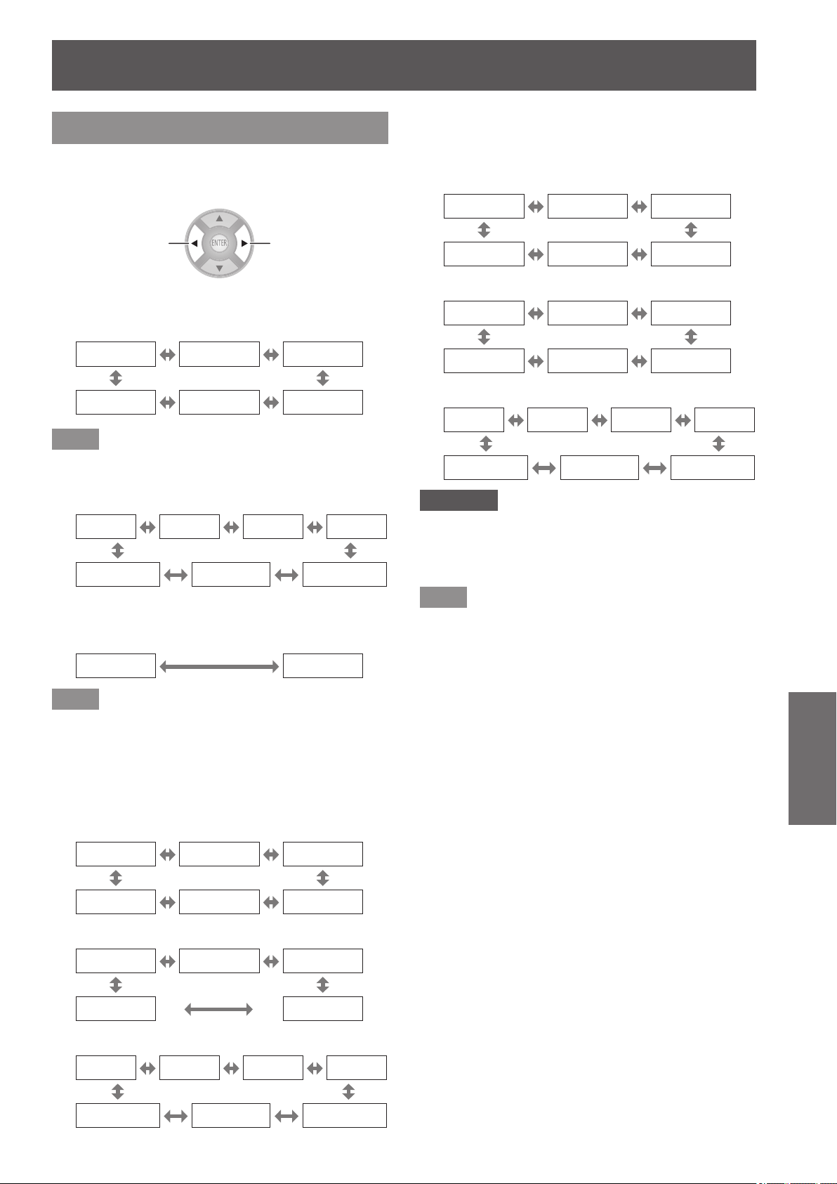
[POSITION] menu
ENGLISH
- 61
Settings
[ASPECT]
You can switch the image aspect ratio manually when
needed.
Aspect ratio depends on signals.
Switch settings Switch settings
■
When a VIDEO/S-VIDEO signal is input
[NTSC/NTSC4.43/PAL-M/PAL60 input]
[AUTO] [4:3] [16:9]
[ZOOM] [JUST] [S16:9]
Note
z
[AUTO] is enabled only when an NTSC signal is input for
both VIDEO and S-VIDEO signals.
[PAL/PAL-N/SECAM input]
[16:9]
[S16:9]
[14:9]
[ZOOM1]
[4:3] [JUST] [ZOOM2]
■
When a COMPUTER (RGB) signal is
input
[4:3] [16:9]
Note
z
If using a 1 280 × 720/60, 1 280 × 768/60, 1 280 x
800/60, WXGA+60, 1 920 x 1 080/50, 1 920 x 1 080/60,
or WUXGA60RB signal, the aspect ratio is xed so this
cannot be switched.
■
HDMI
[1 080/60i, 1 080/50i, 1 080/60p, 1 080/50p,
1 080/24p, 720/60p, 720/50p input]
[16:9] [S16:9] [H-FIT]
[4:3] [ZOOM] [V-FIT]
[480p input]
[16:9] [S16:9] [JUST]
[4:3] [ZOOM]
[576p input]
[16:9]
[S16:9]
[14:9]
[ZOOM1]
[4:3] [JUST] [ZOOM2]
■
COMPONENT signal (YC
B
C
R
/YP
B
P
R
) /
COMPUTER (RGB) signal
[1 080/60i, 1 080/50i, 1 080/60p, 1 080/50p,
1 080/24p, 720/60p, 720/50p input]
[16:9] [S16:9] [H-FIT]
[4:3] [ZOOM] [V-FIT]
[480i/480p input]
[AUTO] [4:3] [16:9]
[ZOOM] [JUST] [S16:9]
[576i/576p input]
[16:9]
[S16:9]
[14:9]
[ZOOM1]
[4:3] [JUST] [ZOOM2]
Attention
z
If a 4:3 aspect video is projected at a 16:9 aspect ratio,
the edges may not be visible or the shape of the image
may change. Please project videos intended by the
author for 4:3 projection at that aspect ratio.
Note
z
If an aspect ratio that differs from the one used in the
input signal is selected, the video will look different from
the original.
z
If you project a copyrighted image enlarged or distorted
by using [ASPECT] function in commercial use in a
public place, such as a restaurant or hotel, you might
infringe on the copyright of the creator which is protected
by copyright law.
z
When set to [AUTO], the aspect ratio is automatically
switched to the optimum aspect ratio when an aspect
ratio identier is included in the input signal.
z
[AUTO] may not be displayed if the input signal is VIDEO
or COMPONENT (YC
B
C
R
/YP
B
P
R
).
z
A black area may appear at the top and bottom of the
screen when videos that are wider than 16:9 (cinema
vision etc.) are projected.
z
When a signal is input that uses overseas broadcasting
formats, the supported aspect ratio modes differ from the
table shown.
z
When a 3D signal is input
*1
, other than for [S16:9], the
aspect ratio set for 2D signal input is not maintained and
16:9 is used for display. When a 3D signal is input the
[ASPECT] setting cannot be switched.
*1 Only when [2D TO 3D] for [3D SETTINGS] menu is set to
[OFF]
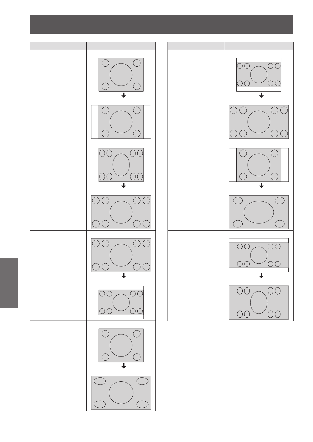
[POSITION] menu
62 -
ENGLISH
Settings
Aspect Screen
[4:3]
Projects at 4:3.
Input signal
Projection screen
[16:9]
Projects at 16:9.
(Enlarged horizontally)
Input signal
Projection screen
[S16:9]
Projects a 16:9 aspect
video onto a 4:3 aspect
screen.
Input signal
Projection screen
[JUST]
Adjusts horizontally to
t 16:9.
When projecting
a 4:3 aspect ratio
video, distortion in the
center of the screen is
reduced.
(Enlarged horizontally)
Input signal
Projection screen
Aspect Screen
[ZOOM]
Enlarges while
preserving original
ratio.
The projected video
may be clipped in
some cases, but
the video can be
accurately reproduced.
Use the ▲ ▼ buttons
to adjust vertically.
(Not available with
HDMI signal.)
Input signal
Projection screen
[H-FIT]
Adjusts horizontally to
t 16:9.
(Enlarged horizontally)
Input signal
Projection screen
[V-FIT]
Adjusts vertically to t
16:9.
(Enlarged vertically)
Use the ▲ ▼ buttons
to adjust vertically.
(Not available with
HDMI signal.)
Input signal
Projection screen
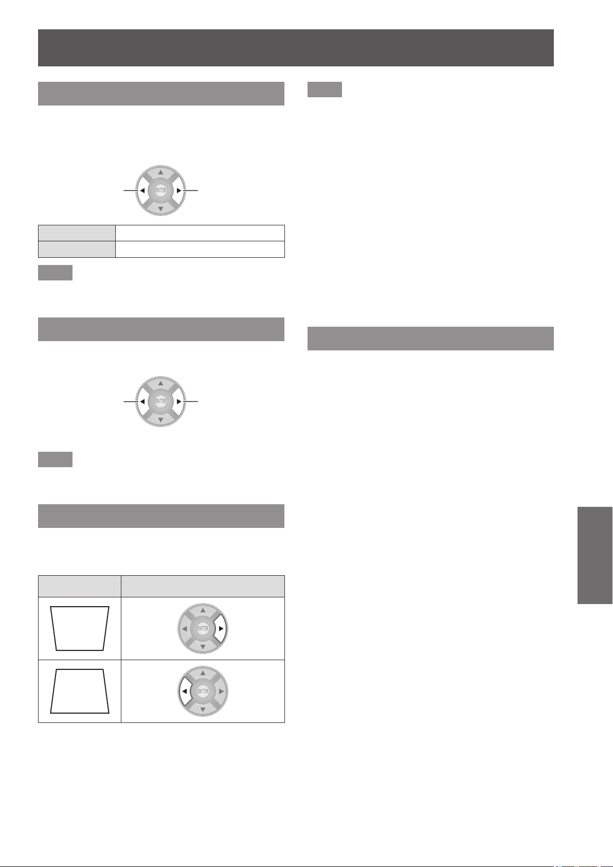
[POSITION] menu
ENGLISH
- 63
Settings
[WSS]
In the European broadcasting system, if the input
signal contains an identication signal, WSS
automatically switches the aspect ratio to the required
setting. (
page 61)
Switch settings Switch settings
[ON] Switch automatically
[OFF] Do not switch automatically
Note
z
Aspect ratio switches only in the case of these input
signals: PAL/625i (576i)/625p (576p)
[OVER SCAN]
If the 4 edges of an image are partly dropped, you can
use this function to adjust and project it properly.
Shrink image
Enlarge image
z
Setting range: 0 to +10
Note
z
COMPUTER signal (exc. movie based signals) is not
supported.
[KEYSTONE]
If the projector is aligned non-perpendicularly to the
screen, or if the projection screen has an angled
surface, you can correct the keystone vertically.
Image Operation
z
Setting range: −32 to +32
Note
z
You can correct the distortion ± 30 degrees from the
vertical plane. However, if there is overcorrection, the
image quality may deteriorate and become blurry. For a
better quality image, installing the projector with minimum
distortion is recommended.
z
When adjustment with [KEYSTONE] carried out, the
vertical center of the screen and the lens need to be
realigned.
z
The result of the keystone correction will affect the size of
the image.
z
Keystone correction does not function on the menu
screen.
z
Some distortion may occur due to lens shift adjustment.
z
The result of the keystone correction may affect the
aspect ratio.
z
When adjustment is performed with keystone correction,
the parallax adjustment result set in the [3D VIEWING
MONITOR] is discarded, and the parallax adjustment
function is disabled.
[AUTO SETUP]
COMPUTER IN (RGB) signals only (exc. movie based
signals)
When you select [AUTO SETUP] and then press the
<ENTER> button, [H-POSITION], [V-POSITION],
[DOT CLOCK], and [CLOCK PHASE] are adjusted
automatically in accordance with the input signal.
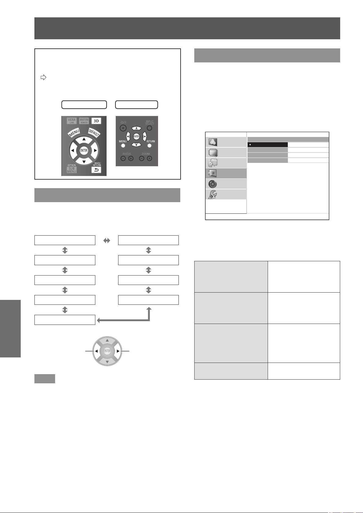
[3D SETTINGS] menu
64 -
ENGLISH
Settings
[3D SETTINGS] menu
Either press the <3D> button on the remote
control or select [3D SETTINGS] from the
main menu in “Navigating through the menu”
(
page 37) and select the item from a submenu.
z
After selecting an item, adjust the screen position
using the ▲▼◄ ► buttons.
Remote control
Projector controls
[SCREEN SIZE]
When viewing 3D video, set the screen size for
projection.
[102 cm (40 inches)] [152 cm (60 inches)]
[508 cm (200 inches)] [203 cm (80 inches)]
[457 cm (180 inches)] [254 cm (100 inches)]
[406 cm (160 inches)] [305 cm (120 inches)]
[356 cm (140 inches)]
Switch settings Switch settings
Note
z
In the case that the actual projection screen size and
the menu size do not match, select a screen size that is
slightly larger than the actual screen size.
z
If [AUTO SWITCHING] in the [LENS CONTROL] menu is
set to [2.35:1 IMAGE DETECTION], set the size to 1.02
m
(40") larger than the actual screen used for projection.
[3D INPUT FORMAT]
In the case that 3D video is not displayed in 3D
correctly, set the 3D format of the projector to the
same one as the connected player. When 3D video is
not displayed correctly using [AUTO], set to [SIDE BY
SIDE] or [TOP AND BOTTOM] in accordance with the
3D video format.
1) Press the <ENTER> button.
z
The [3D INPUT FORMAT] menu is displayed.
3D INPUT FORMAT
AUTO
SIDE BY SIDE
TOP AND BOTTOM
NATIVE
PICTURE
POSITION
LANGUAGE
3D SETTINGS
LENS CONTROL
OPTION
2) Select the 3D format with the ▲ ▼
buttons.
3) Press the <ENTER> button.
[AUTO]
When a 3D video
signal is received, it
automatically changes to
display of 3D video.
[SIDE BY SIDE]
Uses [SIDE BY SIDE]
(two screen conguration
on each side) format for
3D video display.
[TOP AND BOTTOM]
Uses [TOP AND
BOTTOM] (two screen
conguration on top and
bottom) format for 3D
video display.
[NATIVE]
Displays 3D video as 2D
video.
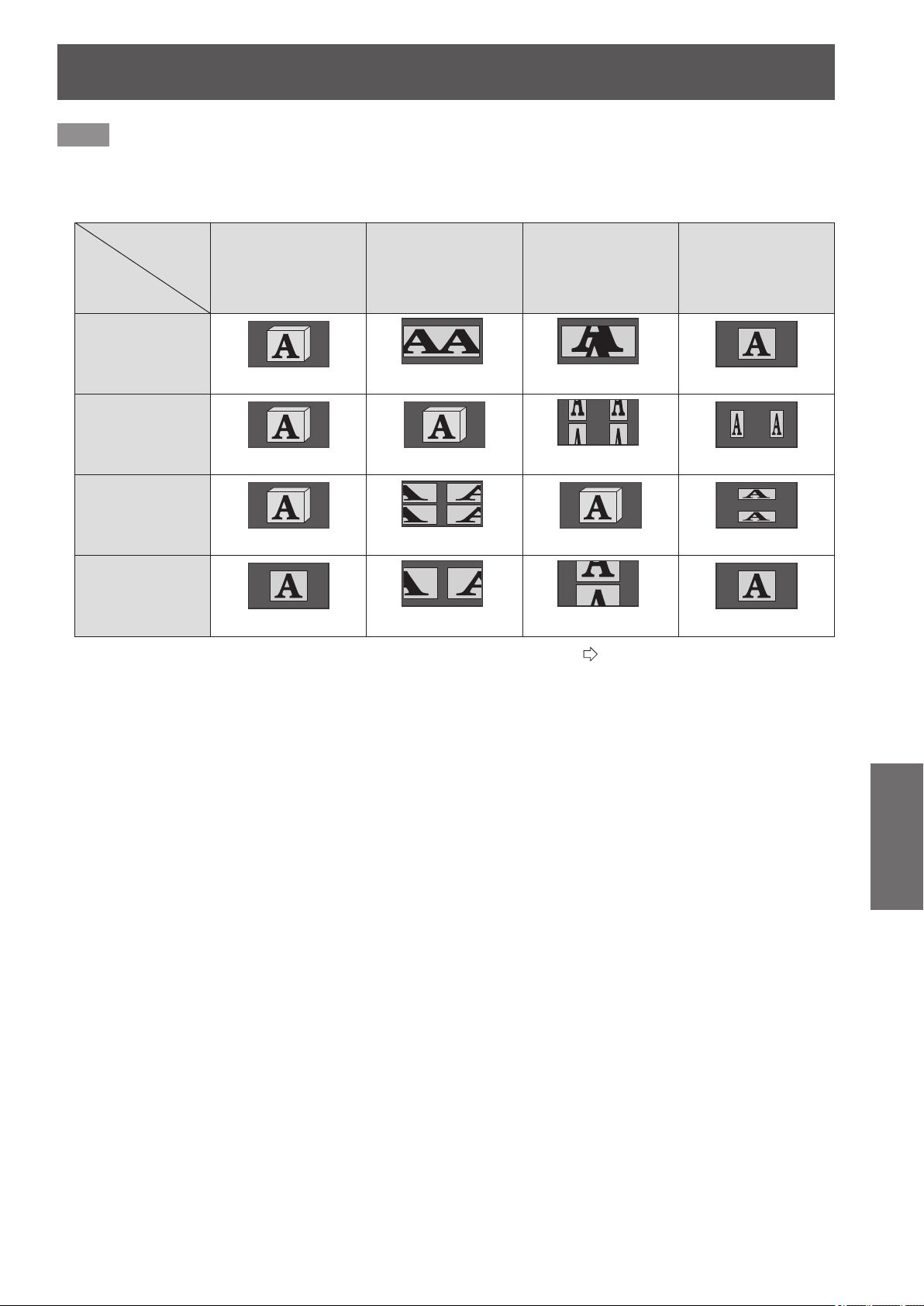
[3D SETTINGS] menu
ENGLISH
- 65
Settings
Note
z
If a setting other than [AUTO] is selected when the input is switched to HDMI, [3D INPUT FORMAT] is changed to [AUTO]
when actions such as turning the power of/on, switching input, or switching the signal are performed on the connected
device.
See the following table regarding settings, input signals and the image for viewing.
Switching 3D
format
Input signal
[AUTO] [SIDE BY SIDE]
[TOP AND
BOTTOM]
[NATIVE]
FRAME
PACKING
(Normal 3D video)
SIDE BY
SIDE
(Normal 3D video
*1
) (Normal 3D video)
TOP AND
BOTTOM
(Normal 3D video
*1
) (Normal 3D video)
2D
*1 Depending on the signal, it is necessary to set [3D INPUT FORMAT]. (
page 64)
z
During 2D to 3D conversion, [3D INPUT FORMAT] cannot be performed.
z
Depending on the device connected, there are cases where it differs from the content described above.
z
A FRAME PACKING signal is a 3D signal for when a Blu-ray 3D compatible disc is played back with a device such as a 3D
compatible Blu-ray player connected using HDMI.
z
The SIDE BY SIDE signal uses two videos arranged next to each other and converts them to a 3D video.
z
A TOP AND BOTTOM signal is when two videos are arranged on top of each other are used and converted to a 3D video.
z
When the freeze function is being used, the [3D INPUT FORMAT] cannot be executed.
z
As regards the “Normal 3D video” shown in the table, a 3D video is available when power is supplied to the 3D Eyewear.
The 3D effect is not achieved if the power supply is cut off.
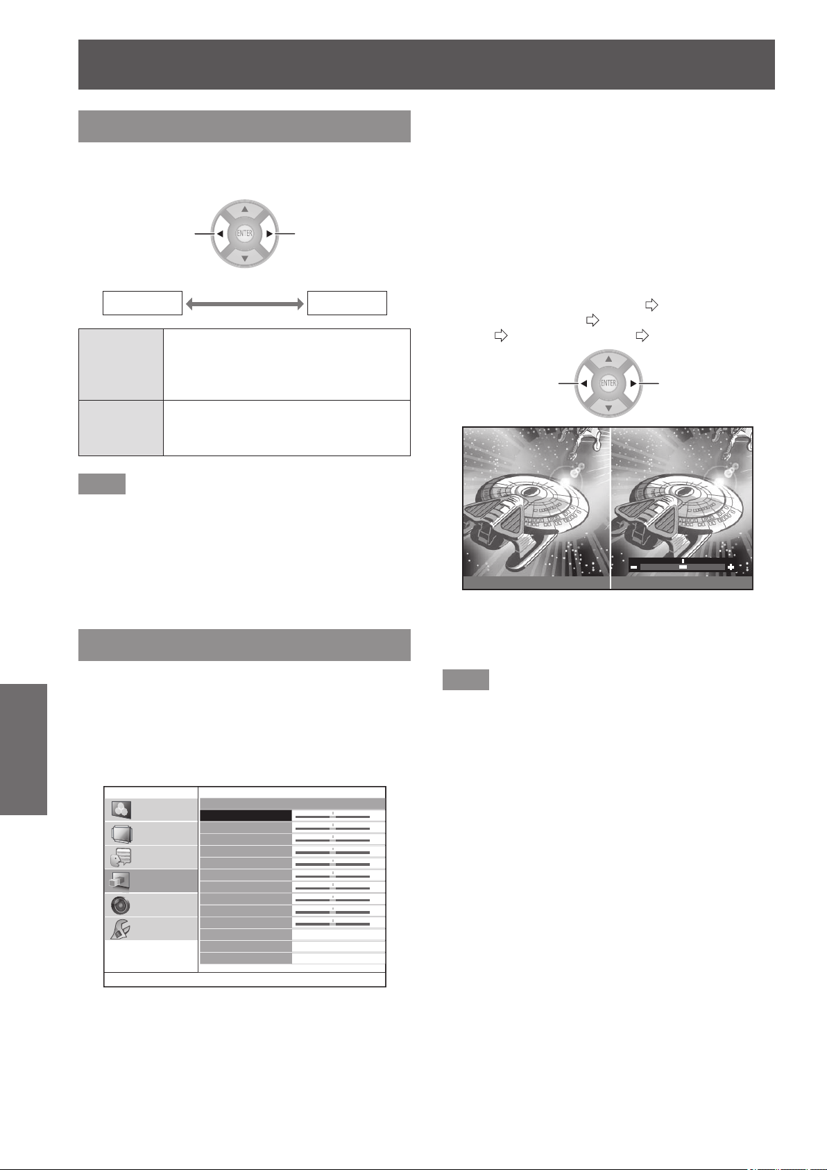
[3D SETTINGS] menu
66 -
ENGLISH
Settings
[LEFT/RIGHT SWAP]
Switch to [SWAPPED] if you feel discomfort when
watching a 3D video with 3D Eyewear.
Switch settings Switch settings
[NORMAL]
[SWAPPED]
[NORMAL]
If the 3D video is being displayed
correctly while the 3D Eyewear is
being worn, do not change from
[NORMAL] settings.
[SWAPPED]
Select this if a feeling of discomfort is
felt towards the 3D video while wearing
3D Eyewear.
Note
z
If 3D video is being correctly displayed in 3D, setting
[LEFT/RIGHT SWAP] to [SWAPPED] may lead to a
dramatic feeling of discomfort. Conrm display of 3D
video and use correctly.
z
When the power supply for the projector is turned off and
on or the input channel is changed, the [LEFT/RIGHT
SWAP] changes to [NORMAL].
[3D PICTURE BALANCE]
With regards to the left eye and right eye video of the
3D video, the difference in the video signal for the
right eye can be adjusted based on that for the left
eye.
Press the <ENTER> button.
z
[3D PICTURE BALANCE] menu is displayed.
3D PICTURE BALANCE
CONTRAST
CONTRAST R
CONTRAST G
CONTRAST B
BRIGHTNESS
BRIGHTNESS R
BRIGHTNESS G
BRIGHTNESS B
COLOR
TINT
3D WAVEFORM MONITOR
PICTURE BALANCE MEMORY
0
0
0
0
0
0
0
0
0
0
PICTURE
POSITION
LANGUAGE
3D SETTINGS
LENS CONTROL
OPTION
■
Adjustment method
1) Press the ▲▼ buttons and select the
item for adjusting the right eye video.
z
The video for the left eye and for the right eye are
shown on the left and the right.
The items that can be adjusted are contrast,
brightness, color, and tint.
2) Use the ◄ ► buttons to change the
value.
z
For details about contrast, brightness, color,
and tint, see [CONTRAST] (
page 40),
[BRIGHTNESS] (
page 40), [COLOR]
(
page 40), and [TINT] (
page 40)
Change the value Change the value
LEFT RIGHT
Current display for left
eye video
(Fixed)
Current display for right
eye video
(Can be adjusted)
Note
z
This is a function to balance 3D video, so do not
intentionally use settings that will upset the balance.
Please take care not to make the balance extremely
uneven as this may lead to a feeling of discomfort.
z
This adjustment function is only active for 3D input
signals and is inactive for 3D video that has been
converted from 2D to 3D.
z
In the case that the settings for the left eye video are
at minimum, the settings for the right eye cannot be set
below them.
In the case that the settings for the left eye video are at
maximum, the settings for the right eye cannot be set
above them.
z
Even if the [LEFT/RIGHT SWAP] setting is used,
adjustment can only be performed on the right eye input
signal.
z
When adjusting the 3D picture balance, keystone
correction is temporarily disabled and menus other than
the [3D PICTURE BALANCE] menu cannot be used.
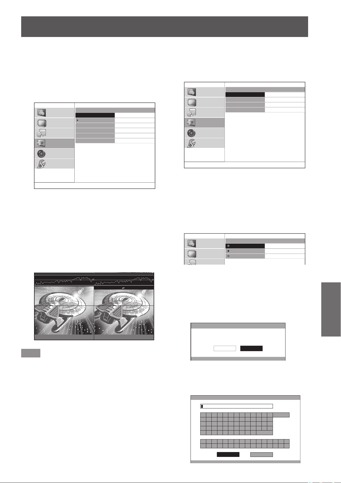
[3D SETTINGS] menu
ENGLISH
- 67
Settings
■
[3D WAVEFORM MONITOR]
For easy balance adjustment, use a video device that
supports 3D and displays the video output (brightness)
level of the 3D video for the left and right eye respectively.
1) Press the <ENTER> button.
z
The [3D WAVEFORM MONITOR] menu is
displayed.
3D WAVEFORM MONITOR
OFF
SINGLE LINE SCAN(Y)
SINGLE LINE SCAN(R)
SINGLE LINE SCAN(G)
SINGLE LINE SCAN(B)
MOVE LINE
PICTURE
POSITION
LANGUAGE
3D SETTINGS
LENS CONTROL
OPTION
2) Press the ▲▼ buttons to select the
required item and press the <ENTER>
button.
3) Select the [MOVE LINE].
4) Press the <ENTER> button.
5) Use the ▲▼ buttons to move the line to
the desired output (brightness) level.
6) Press the <RETURN> button twice.
LEFT RIGHT
100%
50%
0%
ENTER : CHANGE WF MODE : MOVE LINE
Note
z
To hide the waveform monitor, select [OFF] from the [3D
WAVEFORM MONITOR] menu and press the <ENTER>
button.
■
[PICTURE BALANCE MEMORY]
Press the <ENTER> button.
z
[PICTURE BALANCE MEMORY] menu is
displayed.
PICTURE BALANCE MEMORY
MEMORY SAVE
MEMORY LOAD
MEMORY DELETE
MEMORY NAME CHANGE
PICTURE
POSITION
LANGUAGE
3D SETTINGS
LENS CONTROL
OPTION
●
[PICTURE BALANCE MEMORY SAVE]
Balance values set for videos (setting values) can be saved
as favorites.
1) Press the ▲▼ buttons to select [MEMORY
SAVE] and press the <ENTER> button.
z
The [PICTURE BALANCE MEMORY SAVE]
screen is displayed.
PICTURE BALANCE MEMORY SAVE
MEMORY1
MEMORY2
MEMORY3
PICTURE
POSITION
LANGUAGE
★
: Memory with data already stored
☆
: No data stored
2) Press the ▲▼ buttons to select the number
to be saved and press the <ENTER>
button.
z
The [PICTURE BALANCE MEMORY SAVE]
conrmation message is displayed.
PICTURE BALANCE MEMORY SAVE
SAVE THE ADJUSTED VALUE AS MEMORY 1.
CANCELOK
3) Select [OK] with the ◄ ► buttons.
4) Press the <ENTER> button.
z
[PICTURE BALANCE MEMORY NAME INPUT]
screen is displayed.
PICTURE BALANCE MEMORY NAME INPUT
A B C D E F G H I J K L M
N O P Q R S T U V W X Y Z
a b c d e f g h i j k l m
n o p q r s t u v w x y z
1 2 3 4 5 6 7 8 9 0
! " # $ % & '
* + - / = ? @ \ ^
_ ` |
~
( ) < > [ ] { } , . : ;
ALL DELETE
SPACE
OK CANCEL
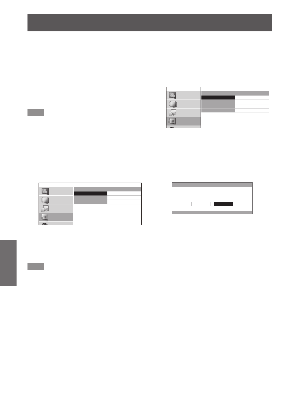
[3D SETTINGS] menu
68 -
ENGLISH
Settings
5) Press the ▲▼◄► buttons to specify the
location of the required character to enter
and press the <ENTER> button.
z
You can enter up to 16 characters.
z
Select [ALL DELETE] and press the <ENTER>
button to erase all input text. If you press the
<DEFAULT> button on the remote control, you
can erase the character currently selected by
the cursor in the input box.
6) Press the ▲▼◄► buttons to select [OK].
7) Press the <ENTER> button.
Note
z
Press the <ENTER> button without entering any text to
keep the default name ([MEMORY1-3]).
●
[PICTURE BALANCE MEMORY LOAD]
You can access the details saved through [PICTURE
BALANCE MEMORY SAVE].
1) Press the ▲▼ buttons to select [MEMORY
LOAD] and press the <ENTER> button.
z
The [PICTURE BALANCE MEMORY LOAD]
menu is displayed.
PICTURE BALANCE MEMORY LOAD
MEMORY1
MEMORY2
MEMORY3
PICTURE
POSITION
LANGUAGE
3D SETTINGS
2) Press the ▲▼ buttons to select the
memory name to be called and press the
<ENTER> button.
z
The video adjustments for the recalled memory
name are switched to.
Note
z
If there are no settings saved in [PICTURE BALANCE
MEMORY SAVE] or if all memory entries have been
deleted with [PICTURE BALANCE MEMORY DELETE],
[PICTURE BALANCE MEMORY LOAD] is not displayed.
●
[PICTURE BALANCE MEMORY DELETE]
You can delete the details saved using [PICTURE
BALANCE MEMORY SAVE].
1) Press the ▲▼ buttons to select [MEMORY
DELETE] and press the <ENTER> button.
z
The [PICTURE BALANCE MEMORY DELETE]
menu is displayed.
PICTURE BALANCE MEMORY DELETE
MEMORY1
MEMORY2
MEMORY3
ALL DELETE
PICTURE
POSITION
LANGUAGE
3D SETTINGS
2) Press the ▲▼ buttons to select the
memory name to be deleted and press the
<ENTER> button.
z
Press the ▲▼ buttons to select [ALL DELETE]
to delete all the details saved using [PICTURE
BALANCE MEMORY SAVE].
z
A [PICTURE BALANCE MEMORY DELETE]
conrmation message is displayed.
PICTURE BALANCE MEMORY DELETE
DELETE THE MEMORY 1 DATA.
CANCELOK
3) Select [OK] with the ◄ ► buttons.
4) Press the <ENTER> button.
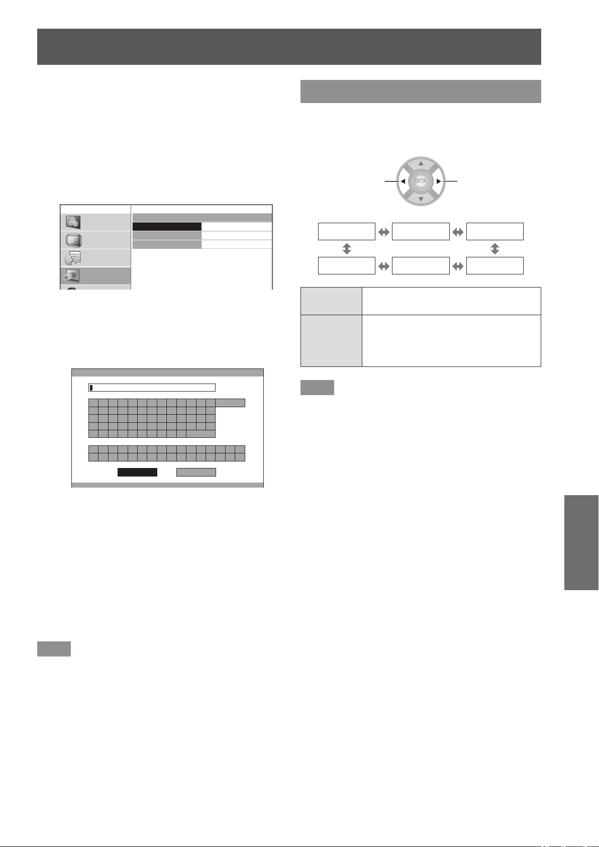
[3D SETTINGS] menu
ENGLISH
- 69
Settings
●
[PICTURE BALANCE MEMORY NAME
CHANGE]
You can edit the memory name of details saved using
[PICTURE BALANCE MEMORY SAVE].
1) Press the ▲▼ buttons to select [MEMORY
NAME CHANGE] and press the <ENTER>
button.
z
The [PICTURE BALANCE MEMORY NAME
CHANGE] menu is displayed.
PICTURE BALANCE MEMORY NAME CHANGE
MEMORY1
MEMORY2
MEMORY3
PICTURE
POSITION
LANGUAGE
3D SETTINGS
2) Press the ▲▼ buttons to select the
memory name to be changed and press the
<ENTER> button.
z
The [PICTURE BALANCE MEMORY NAME
INPUT] screen is displayed.
PICTURE BALANCE MEMORY NAME INPUT
A B C D E F G H I J K L M
N O P Q R S T U V W X Y Z
a b c d e f g h i j k l m
n o p q r s t u v w x y z
1 2 3 4 5 6 7 8 9 0
! " # $ % & '
* + - / = ? @ \ ^
_ ` |
~
( ) < > [ ] { } , . : ;
ALL DELETE
SPACE
OK CANCEL
3) Press the ▲▼◄► buttons to specify the
location of the required character to enter
and press the <ENTER> button.
z
You can enter up to 16 characters.
z
Select [ALL DELETE] and press the <ENTER>
button to erase all input text. If you press the
<DEFAULT> button on the remote control, you
can erase the character currently selected by
the cursor in the input box.
4) Press the ▲▼◄► buttons to select [OK].
5) Press the <ENTER> button.
Note
z
Press the <ENTER> button without entering any text to
keep the default name ([MEMORY1-3]).
[2D TO 3D]
2D video is quasi converted to 3D video and shown.
Select from [MODE1] to [MODE5] based on
preference.
Switch settings Switch settings
[OFF] [MODE1] [MODE2]
[MODE5] [MODE4] [MODE3]
[OFF]
2D video is not converted to 3D video.
Can be enjoyed as 2D video.
[MODE1] -
[MODE5]
2D video is converted to 3D video and
shown.
Use this feature with your mode of
preference.
Note
z
When actions are performed on the projector such as
switching off or on, switching input, or switching the
signal, [2D TO 3D] is changed to [OFF].
z
Depending on the video, there are cases where it is not
converted correctly.
z
When using this function, there are differences in how the
video is viewed compared to the original based on the
video conversion on the device side so keep this in mind
when using.
z
Note that position adjustment of the screen and area
position adjustment of lens control will cause differences
in how the video is viewed.
z
This does not support input from the VIDEO/S-VIDEO
terminal.
z
For computer (RGB) signals, only 1 920 x 1 080 and
1 280 x 720 signals are supported.
z
If you project a copyrighted image converted from 2D to
3D by using this function for commercial use in a public
place, such as a restaurant or hotel, you may infringe
upon the creator’s copyright which is protected by
copyright law.
z
When the menu disappears, the screen may momentarily
shake horizontally.
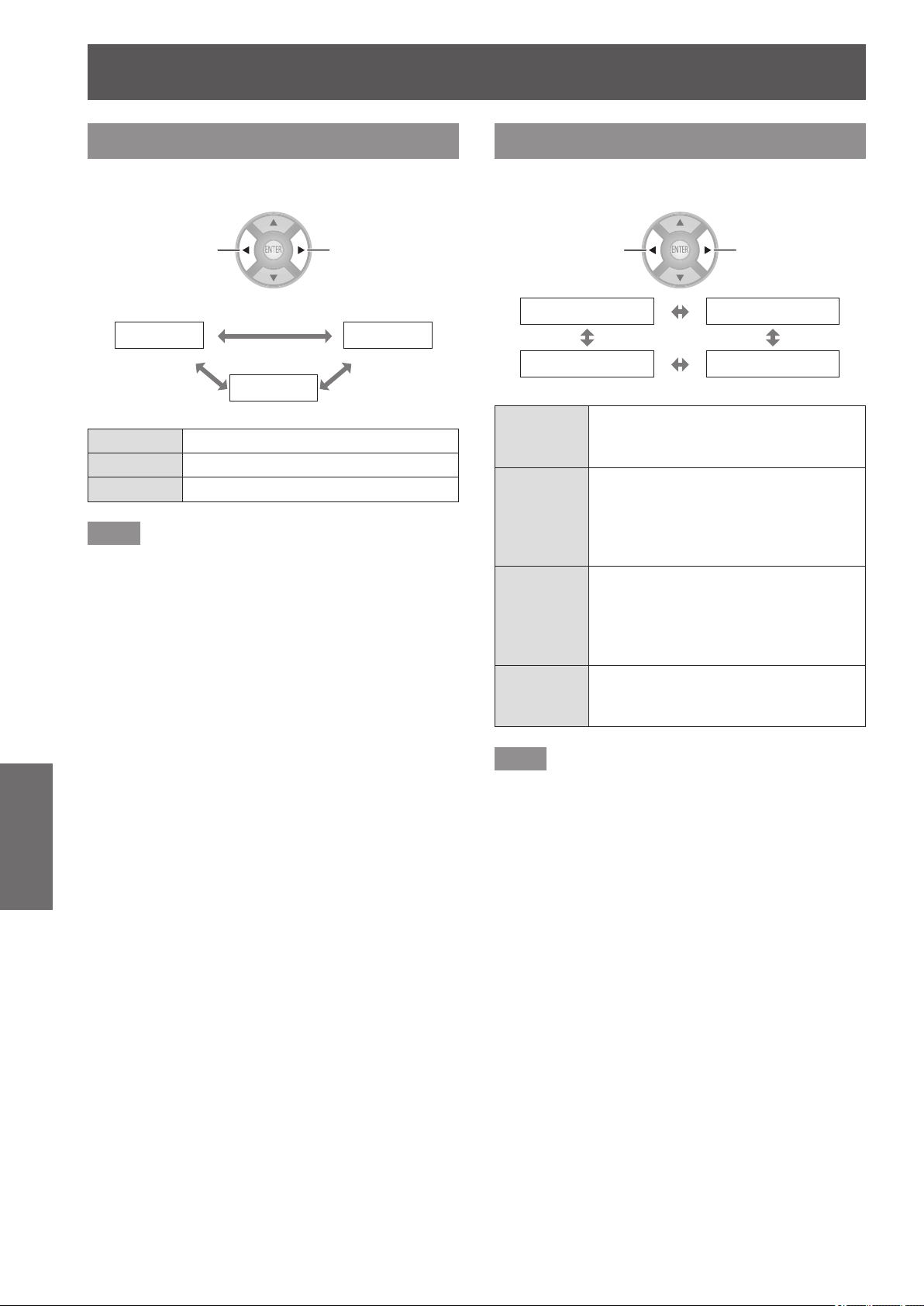
[3D SETTINGS] menu
70 -
ENGLISH
Settings
[3D EYEWEAR BRIGHTNESS]
This enables adjusting the brightness for the 3D
Eyewear.
Switch settings Switch settings
[LIGHT] [DARK]
[NORMAL]
[LIGHT] Select to brighten the 3D video display.
[NORMAL] Select this as standard for 3D viewing
[DARK] Select to reduce 3D video afterimage.
Note
z
When you switch the brightness of 3D Eyewear, the
screen may momentarily appear jumbled.
[3D IR TRANSMITTER]
This controls the 3D IR Transmitter embedded in this
projector.
Switch settings Switch settings
[OFF] [WEAK]
[STRONG] [MEDIUM]
[STRONG]
This sets the IR output of the 3D IR
Transmitter to high.
Select this when viewing 3D video.
[MEDIUM]
This sets the IR output of the 3D IR
Transmitter to middle. Select this when
the response of the remote control of
the projector or the external device is
poor.
[WEAK]
This sets the IR output of the 3D IR
Transmitter to low.
Select this when the response of the
remote control is poor even when set
to [MEDIUM].
[OFF]
This sets the IR output of the 3D IR
Transmitter to off.
Select this when not viewing 3D video.
Note
z
If you feel that the response of the remote control for
this projector or external devices is poor when using the
built-in 3D IR Transmitter, rst set to [MEDIUM]. If no
improvements are seen, set to [WEAK].
z
This menu cannot be used to control the external 3D IR
transmitter (optional accessory).
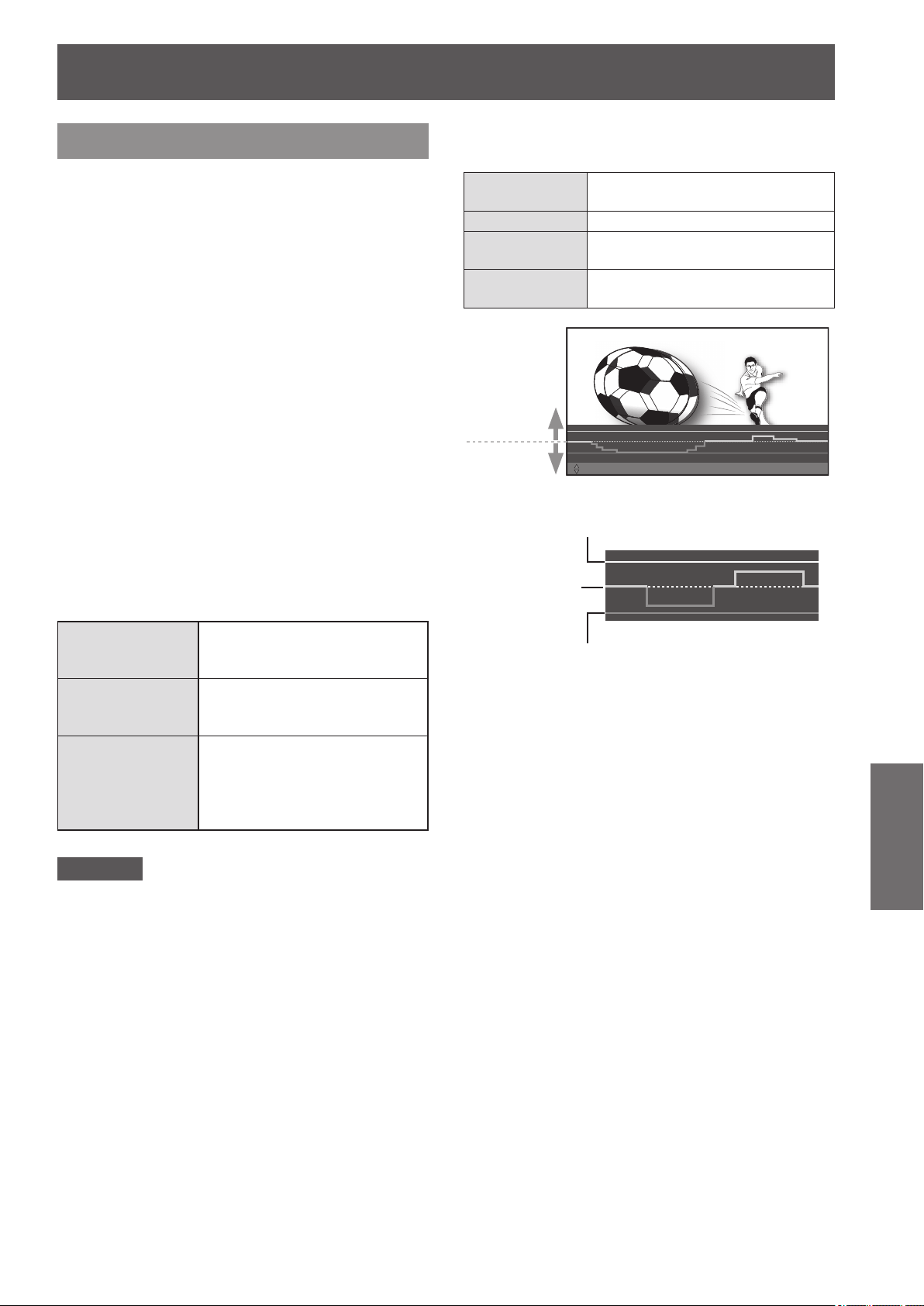
[3D SETTINGS] menu
ENGLISH
- 71
Settings
[3D VIEWING MONITOR]
In the 3D video the depth of eld effects in front of and
into the screen are adjusted while conrming on the
monitor display.
1) Press the ◄► buttons to select [MODE1]
- [MODE3], and press the <ENTER>
button.
z
The parallax adjustment monitor is displayed.
The display content of each mode is described
below.
2) Press the ▲▼ buttons to select the
optimum parallax.
z
Press the <DEFAULT> button to return to
pre-adjustment settings.
z
Press the <FUNCTION> button to freeze and
unfreeze.
3) Press the <ENTER> button.
4) When you have nished making
adjustments, press the <RETURN>
button to return to [3D SETTINGS].
The display content of each mode in the parallax
adjustment monitor is as follows.
[Mode1]
Displays the parallax of the
entire image at the bottom of the
projection screen.
[Mode2]
Displays the maximum parallax
of the entire image in one
dimension.
[Mode3]
Displays the parallax of the
entire image by superimposing
on the image. (The image is in
monochrome signals, and only
the parallax is colored.)
Attention
z
If the red line of the in front of screen parallax descends
below the area demarcated by the reference line (white
dashed line) and the lower maximum line (white solid
line), or if the blue line of the into screen parallax ascends
above the area demarcated by the reference line (white
dashed line) and the upper maximum line (white solid
line), then make sure to watch from a large enough
distance from the screen or stop watching.
For explanation about each line, refer to the following
explanation for [Mode 1].
The lines on the parallax adjustment monitor in
[Mode1] display the following content:
White
(dashed line)
Default display for video without
parallax
Blue Displays the into screen parallax
Red
Displays the in front of screen
parallax
White
(solid line)
Displays an estimate for parallax of
general 3D video
Into screen
parallax
In front of
screen parallax
ADJUST
ƷƷ
ENTER : APPLY
ƷƷ
DEFAULT : RESET
ƷƷ
FUNCTION : FREEZE
This indicates the maximum estimate
in front of screen parallax while measuring.
This indicates the maximum estimate
into screen parallax while measuring.
Reference
line
* The illustration shown here depicts how an image is
projected.
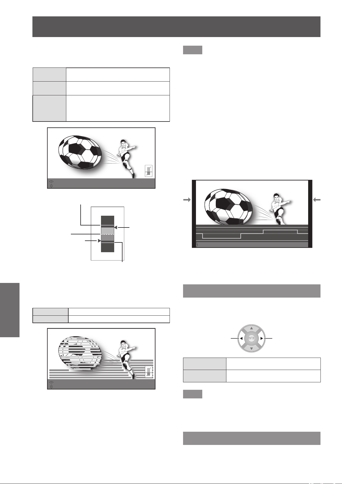
[3D SETTINGS] menu
72 -
ENGLISH
Settings
The gauge display of the one-dimensional display on
the parallax adjustment monitor of [Mode2] or [Mode3]
indicates the following content:
Blue gauge
Displays the maximum value of the into
screen parallax
Red gauge
Displays the maximum value of the in
front of screen parallax
Triangular
point
Displays the peak of the parallax of the
entire image during the last one second
(left side: In front of screen parallax, right
side: Into screen parallax)
ADJUSTƷƷENTER : APPLYƷƷDEFAULT : RESETƷƷFUNCTION : FREEZE
MOVE DISPLAY
Peak of the in
front of screen
parallax
Peak of the
into screen
parallax
This indicates the maximum estimate
in front of screen parallax while measuring.
This indicates the maximum estimate
into screen parallax while measuring.
Reference
line
* The illustration shown here depicts how an image is
projected.
The parallax distribution display on the parallax adjustment
monitor in [Mode3] indicates the following content:
Blue display Displays the into screen parallax
Red display Displays the in front of screen parallax
ADJUSTƷƷENTER : APPLYƷƷDEFAULT : RESETƷƷFUNCTION : FREEZE
MOVE DISPLAY SUB MENU : CHANGE SENSITIVITY HIGH SENSITIVITY
* The illustration shown here depicts how an image is projected.
Note
z
In [Mode2] and [Mode3], the display position can be
moved left and right with the ◄ ► buttons.
z
In [Mode3], the detection level of the parallax can be
changed with the <SUB MENU> button. Low level and
high level can be switched by pressing the button each
time. The default setting is high level.
z
In the cases such as 3D video input has a very large parallax
or in dark scenes, the correct parallax may not be detected.
z
If the depth of eld effects in front of and into the screen
for the 3D video parallax are set stronger than the
target, this may cause some individuals to feel extreme
discomfort or fatigue. Adjust the parallax so as to not
exceed target displaying (white (solid line)).
z
When an action is performed such as switching the
power off and on, switching input, or switching the signal,
the parallax adjustment set becomes inactive.
z
When adjusting the parallax using the [3D VIEWING
MONITOR], the ends on both sides of the video are
masked. Also note that the aspect size is changed.
ADJUSTƷƷENTER : APPLYƷƷDEFAULT : RESETƷƷFUNCTION : CANCEL FREEZE
* The illustration shown here depicts how an image is
projected.
z
The [3D VIEWING MONITOR] is disabled during
keystone correction.
[3D MOTION REMASTER]
During the display of 3D images, a smooth operation
in which the continuity of parallax is maintained is
realized.
Switch settings Switch settings
[ON] Active
[OFF] Inactive
Note
z
This function is only active for 3D input signals and is
inactive for 3D video that has been converted from 2D to 3D.
z
When [FRAME CREATION] is [OFF], [3D MOTION
REMASTER] cannot be performed.
[3D SAFETY PRECAUTIONS]
A request message regarding 3D viewing is displayed.
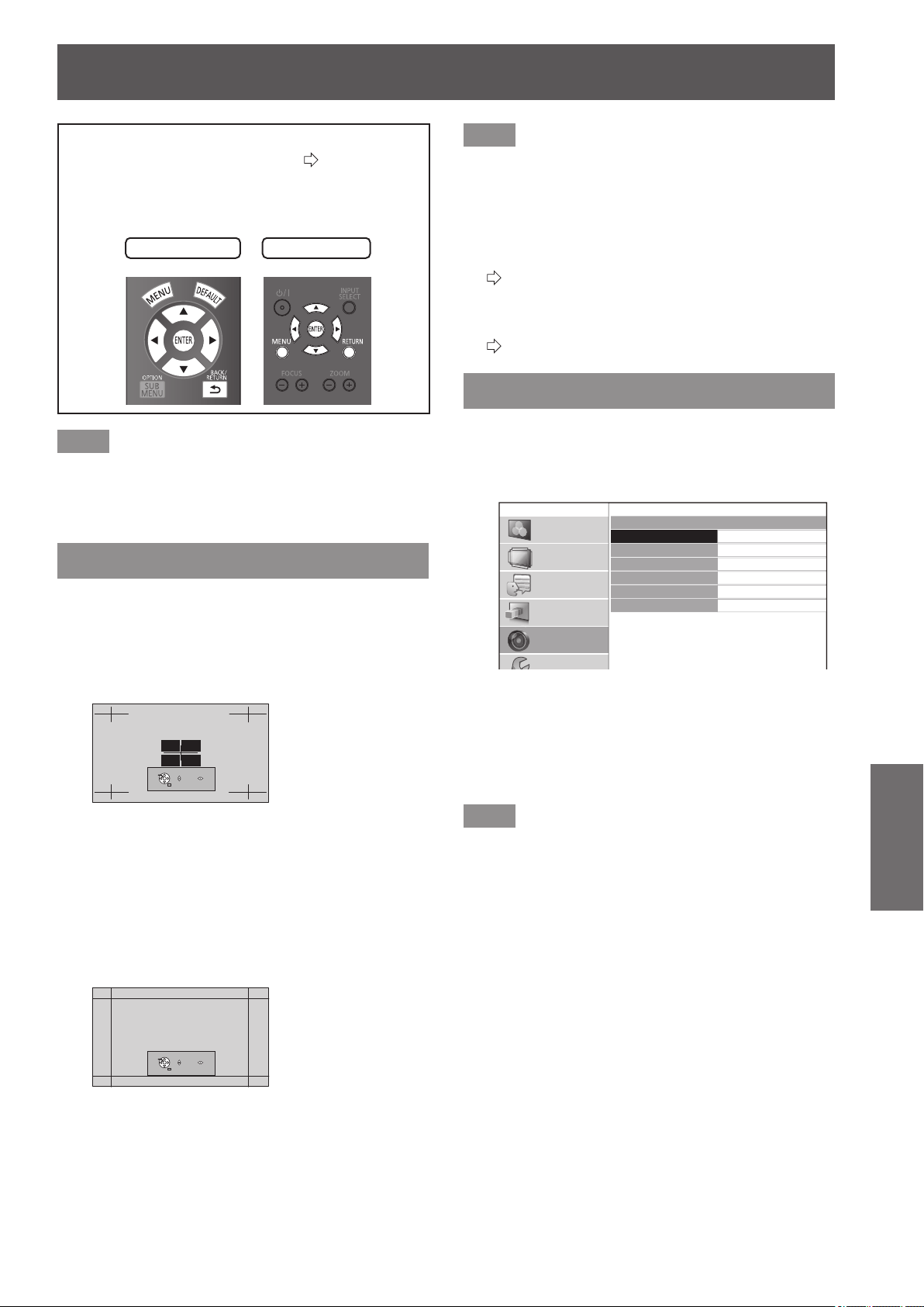
[LENS CONTROL] menu
ENGLISH
- 73
Settings
Select [LENS CONTROL] from the main menu of
“Navigating through the menu” (
page 37), and
choose an item from the submenu.
z
After selecting an item, adjust the screen position
using the ▲▼◄ ► buttons.
Remote control
Projector controls
Note
z
During the display of 3D images, you cannot use
[AUTO SWITCHING], [LEFT MASKING AREA], [RIGHT
MASKING AREA], [UPPER MASKING AREA], [LOWER
MASKING AREA].
[ZOOM/FOCUS]
[ZOOM/FOCUS] test pattern 1 is displayed.
Adjust so that the pattern size and focus are correct.
z
During the display of 3D images, a pattern that can
conrm the stereoscopic effect is displayed.
z
During the display of 3D images, Test pattern 2 is not
displayed.
PATTERN CHANGE
RETURN
FOCUS ZOOM
Test pattern 1
1) Press the ◄► buttons to adjust the
[ZOOM] and ▲▼ to adjust the [FOCUS].
2) Press the <ENTER> button.
z
Test pattern 2 is displayed.
Recheck the focus.
Press the <ENTER> button once more to switch to
the input video, and press it once again to return to
test pattern 1.
PATTERN CHANGE
RETURN
FOCUS ZOOM
Test pattern 2
3) Press the <RETURN> button or <MENU>
button.
z
This returns you to the [LENS CONTROL] menu.
Note
z
The [ZOOM/FOCUS] test pattern displayed on last use is
displayed rst.
z
If the projector or the screen is angled, the top and
bottom edges of the image will become out of focus.
Align the focus to the center of the screen.
z
If keystone distortion occurs, adjust [KEYSTONE] from
the [POSITION] menu.
(
page 63)
z
For details of how to control the lens with the remote
control, see “Managing the lens control settings” in
“Remote control operation”.
(
page 32)
[LENS MEMORY LOAD]
You can recall saved zoom/focus adjustment
positions, horizontal video position, vertical video
position, mask amount adjustment values, or aspect
ratio settings.
LENS MEMORY LOAD
LENS MEMORY1
LENS MEMORY2
LENS MEMORY3
LENS MEMORY4
LENS MEMORY5
LENS MEMORY6
PICTURE
POSITION
LANGUAGE
3D SETTINGS
LENS CONTROL
OPTION
1) Press the ▲▼ buttons to select the
memory name to be recalled.
2) Press the <ENTER> button.
z
The video adjustments for the recalled memory are
switched to.
Note
z
This lens memory function is not 100% guaranteed to
reproduce adjustments.
z
If the power is switched off during [LENS MEMORY
LOAD], when the power is switched back on may be in
the state before the power was switched off. In this case,
readjust the zoom and focus.
z
If a setting is not saved using [LENS MEMORY SAVE]
or all memories are deleted using [LENS MEMORY
DELETE] in the [LENS MEMORY EDIT] menu, the [LENS
MEMORY LOAD] menu will not be displayed.
[LENS CONTROL] menu
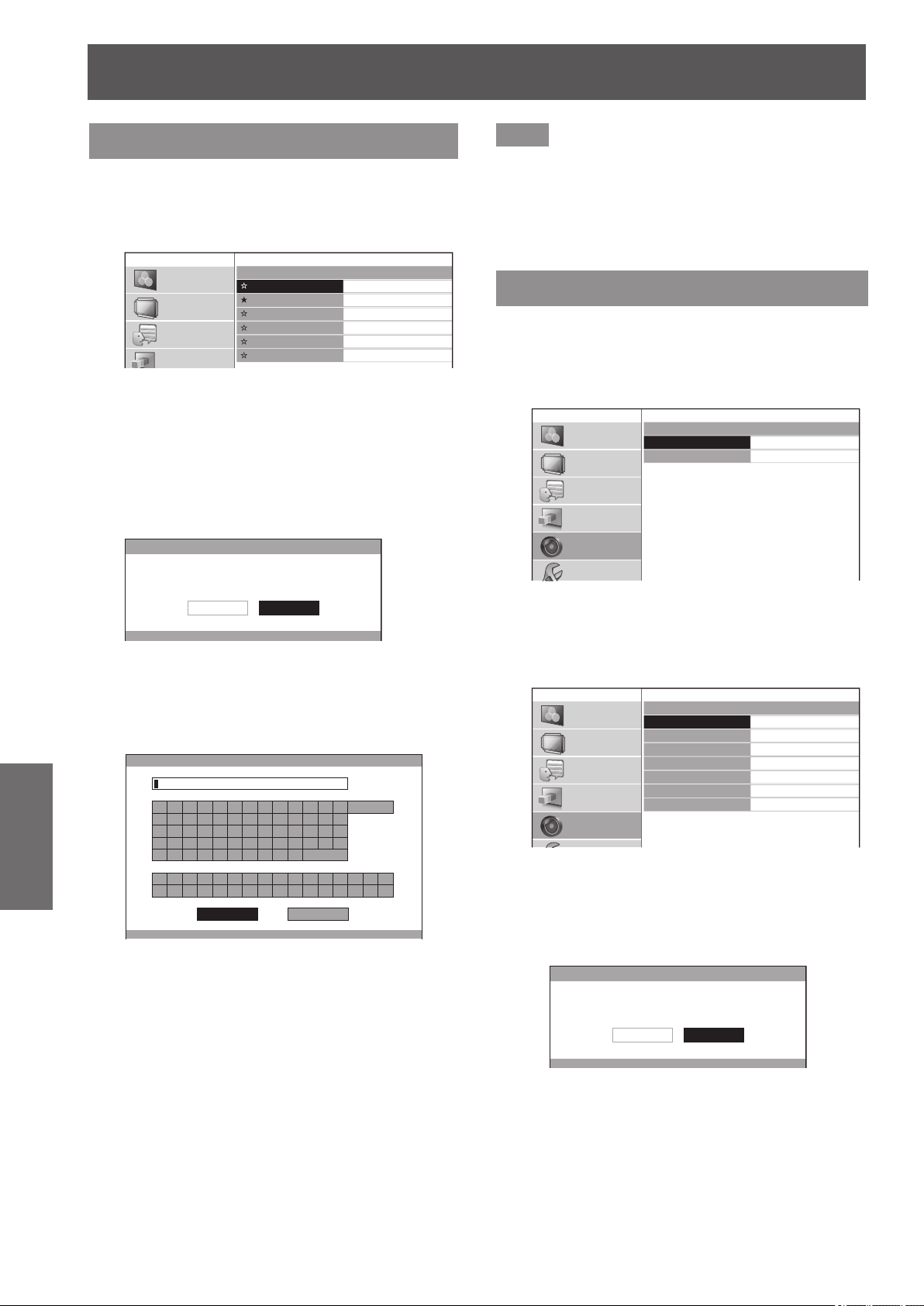
[LENS CONTROL] menu
74 -
ENGLISH
Settings
[LENS MEMORY SAVE]
This enables saving zoom and focus adjustment
position, horizontal video position, vertical video
position, adjustment for amount of mask, and aspect
settings.
LENS MEMORY SAVE
LENS MEMORY1
LENS MEMORY2
LENS MEMORY3
LENS MEMORY4
LENS MEMORY5
LENS MEMORY6
PICTURE
POSITION
LANGUAGE
3D SETTINGS
★
: Memory with data already stored
☆
: No data stored
1) Press the ▲▼ buttons to select the
memory to be saved.
2) Press the <ENTER> button.
z
The [LENS MEMORY SAVE] conrmation message
is displayed.
LENS MEMORY SAVE
SAVE THE ADJUSTED VALUE AS LENS MEMORY 1.
CANCELOK
3) Select [OK] with the ◄ ► buttons.
4) Press the <ENTER> button.
z
[LENS MEMORY NAME INPUT] screen is
displayed.
LENS MEMORY NAME INPUT
A B C D E F G H I J K L M
N O P Q R S T U V W X Y Z
a b c d e f g h i j k l m
n o p q r s t u v w x y z
1 2 3 4 5 6 7 8 9 0
! " # $ % & '
* + - / = ? @ \ ^
_ ` |
~
( ) < > [ ] { } , . : ;
ALL DELETE
SPACE
OK CANCEL
5) Press the ▲▼◄► buttons to specify
the location of the required character to
enter and press the <ENTER> button.
z
You can enter up to 16 characters.
z
Select [ALL DELETE] and press the <ENTER>
button to erase all input text. If you press the
<DEFAULT> button on the remote control, you
can erase the character currently selected by the
cursor in the input box.
6) Press the ▲▼◄► buttons to select [OK].
7) Press the <ENTER> button.
Note
z
Press the <ENTER> button without entering any text to
keep the default name ([LENS MEMORY1-6]).
z
This lens memory function is not 100% guaranteed to
reproduce adjustments.
z
If the power is switched off during [LENS MEMORY
SAVE], re-perform [LENS MEMORY SAVE].
[LENS MEMORY EDIT]
You can delete memory entries and edit the memory
name settings.
Press the <ENTER> button.
z
[LENS MEMORY EDIT] menu is displayed.
LENS MEMORY EDIT
LENS MEMORY DELETE
LENS MEMORY NAME CHANGE
PICTURE
POSITION
LANGUAGE
3D SETTINGS
LENS CONTROL
OPTION
■
[LENS MEMORY DELETE]
1) Press the ▲ ▼ buttons and select the
memory name to be deleted.
LENS MEMORY DELETE
LENS MEMORY1
LENS MEMORY2
LENS MEMORY3
LENS MEMORY4
LENS MEMORY5
LENS MEMORY6
ALL DELETE
PICTURE
POSITION
LANGUAGE
3D SETTINGS
LENS CONTROL
z
Select [ALL DELETE] to delete all lens memory
entries.
2) Press the <ENTER> button.
z
A [LENS MEMORY DELETE] conrmation
message is displayed.
LENS MEMORY DELETE
DELETE THE LENS MEMORY 1 DATA.
CANCELOK
3) Select [OK] with the ◄ ► buttons.
4) Press the <ENTER> button.
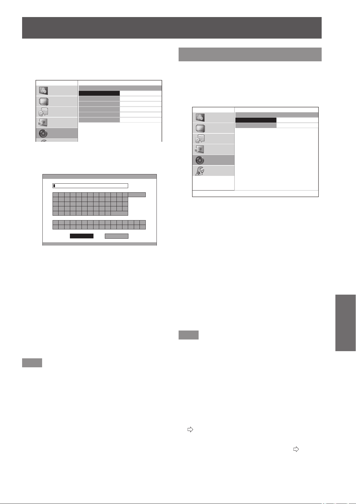
[LENS CONTROL] menu
ENGLISH
- 75
Settings
■
[LENS MEMORY NAME CHANGE]
1) Press the ▲▼ buttons to select the
memory name to be changed.
LENS MEMORY NAME CHANGE
LENS MEMORY1
LENS MEMORY2
LENS MEMORY3
LENS MEMORY4
LENS MEMORY5
LENS MEMORY6
PICTURE
POSITION
LANGUAGE
3D SETTINGS
LENS CONTROL
2) Press the <ENTER> button.
z
[LENS MEMORY NAME INPUT] screen is
displayed.
LENS MEMORY NAME INPUT
A B C D E F G H I J K L M
N O P Q R S T U V W X Y Z
a b c d e f g h i j k l m
n o p q r s t u v w x y z
1 2 3 4 5 6 7 8 9 0
! " # $ % & '
* + - / = ? @ \ ^
_ ` |
~
( ) < > [ ] { } , . : ;
ALL DELETE
SPACE
OK CANCEL
3) Press the ▲▼◄► buttons to specify
the location of the required character
to enter and press the <ENTER>
button.
z
You can enter up to 16 characters.
z
Select [ALL DELETE] and press the <ENTER>
button to erase all input text. If you press the
<DEFAULT> button on the remote control, you
can erase the character currently selected by
the cursor in the input box.
4) Press the ▲▼◄► buttons to select
[OK].
5) Press the <ENTER> button.
Note
z
Press the <ENTER> button without entering any text
to keep the default name ([LENS MEMORY 1] - [LENS
MEMORY 6]).
[AUTO SWITCHING]
This function automatically identies wide signal
*1
or
16:9/4:3 and automatically recalls memory settings
that have been set for each screen size.
*1 : Wide signals are 2.35:1, 2.40:1, 2.50:1, 2.55:1 aspect
signals.
AUTO SWITCHING
2.35:1 IMAGE DETECTION
16:9 IMAGE DETECTION
OFF
OFF
PICTURE
POSITION
LANGUAGE
3D SETTINGS
LENS CONTROL
OPTION
1) Press the ▲▼ buttons and select the
item for automatic identication.
2) Press the ◄► buttons to select your
required lens memory for automatic
identication.
z
The [LENS MEMORY] setting which has been
selected for [2.35:1 IMAGE DETECTION] is loaded
after a given period of time once the input signal
switches from 16:9/4:3 to 2.35:1.
z
The [LENS MEMORY] setting which has been
selected for [16:9 IMAGE DETECTION] is loaded
after a given period of time once the input signal
switches from 2.35:1 to 16:9/4:3.
z
If [OFF] is selected, automatic identication will not
be performed.
z
This function is not available when [ZOOM] or
[V-FIT] is selected from the [ASPECT] menu.
Note
z
If the lens memory is not registered using [LENS
MEMORY SAVE], you cannot select [AUTO
SWITCHING].
z
When displaying the menu or test pattern, automatic
identication is not performed.
z
Image size may not be correctly recognized if there
is noise in the picture or external device generates
noise. Image size may also not be correctly recognized
depending on the video.
z
Image size may not be correctly recognized if the input
signal level from the external device is not set to the
suggested value range. In this case, adjust the input
signal level using the [WAVEFORM MONITOR] menu.
(
page 41)
z
Image size may not be correctly recognized if the screen
position is not correctly adjusted. In this case, adjust the
screen position using the [POSITION] menu. (
page 60)
z
During the display of 3D images, you cannot use [AUTO
SWITCHING].
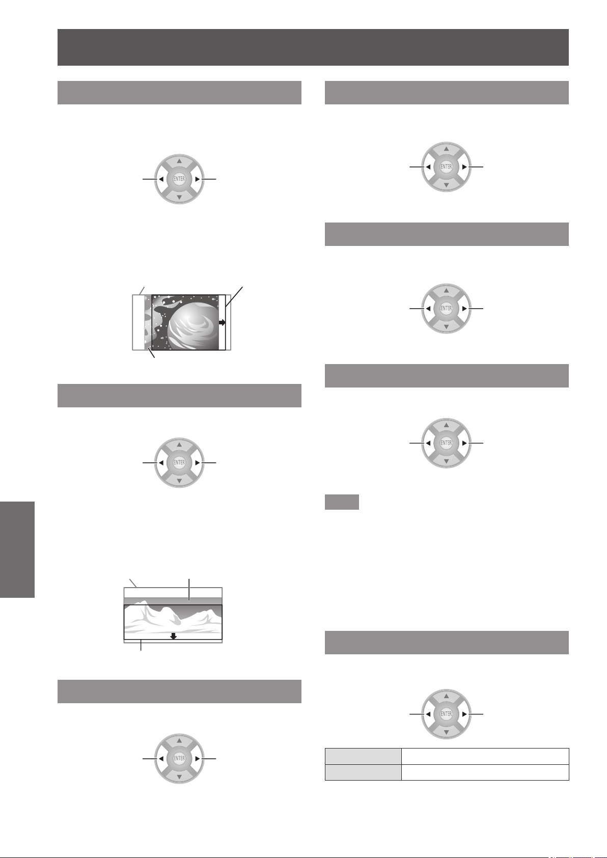
[LENS CONTROL] menu
76 -
ENGLISH
Settings
[H-AREA POSITION]
You can move the frame area horizontally, such as
aligning the right or left frame edge to the screen
edge.
Moving left
Moving right
For example, when projecting an overscanned 16:9
projection area at a 4:3 aspect ratio on a 4:3 aspect
screen, you can adjust the horizontal discrepancy
between the screen position and the video display
position.
16:9 projection area
4:3 screen
4:3 video display position
[V-AREA POSITION]
You can move the frame area vertically, such as aligning
the top or bottom frame edge to the screen edge.
Moving
downward
Moving upward
For example, when projecting an overscanned 16:9
projection area at a 2.35:1 cinema scope screen
movie on a 2.35:1 size cinema scope screen, you can
adjust the vertical discrepancy between the screen
position and the video display position.
2.35:1 cinema scope screen
size video display position
16:9 projection area
2.35:1 cinema scope screen
[LEFT MASKING AREA]
You can place a blank (mask) area in the left side edge on
the screen
.
Less More
z
Setting range: 0 to 70
[RIGHT MASKING AREA]
You can place a blank (mask) area in the right side edge on
the screen
.
Less More
z
Setting range: 0 to 70
[UPPER MASKING AREA]
You can place a blank (mask) area in the upper side edge
on the screen
.
Less More
z
Setting range: 0 to 70
[LOWER MASKING AREA]
You can place a blank (mask) area in the lower side edge
on the screen
.
Less More
z
Setting range: 0 to 70
Note
z
If it is set to [0], each masking function will be invalid.
z
The [MASKING AREA] function will be invalid when
adjusting the [COLOR MANAGEMENT] or [SPLIT
ADJUST] settings, when displaying the [TEST PATTERN]
or [WAVEFORM MONITOR], or when no signal is
detected.
z
During the display of 3D images, you cannot use [LEFT
MASKING AREA], [RIGHT MASKING AREA], [UPPER
MASKING AREA], [LOWER MASKING AREA].
[PROCESSING MESSAGE]
You can set whether to show or hide the execution
message during switching of lens settings.
Switch settings Switch settings
[ON] Show the execution message
[OFF] Hide the execution message
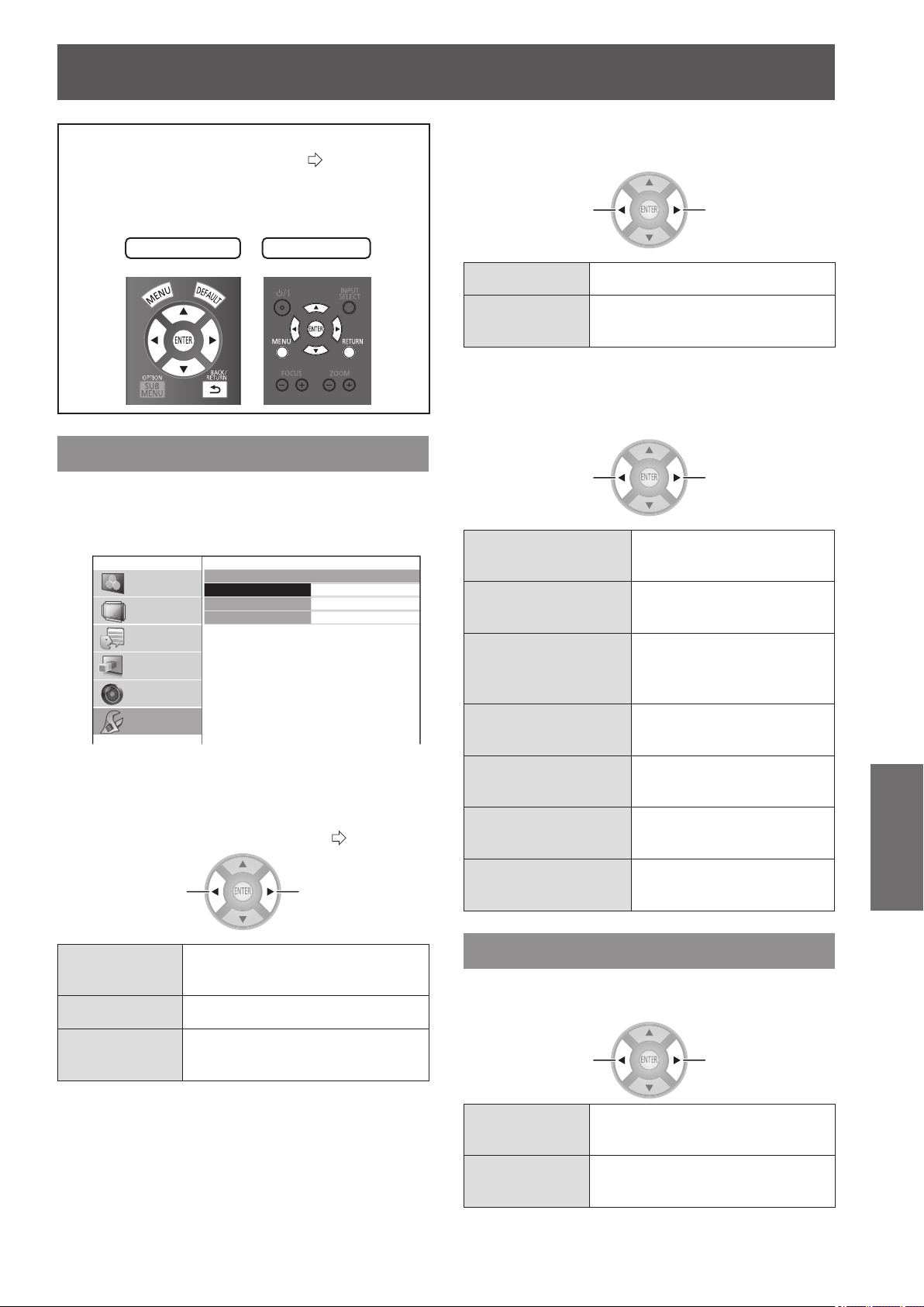
[OPTION] menu
ENGLISH
- 77
Settings
[OPTION] menu
Select [OPTION] from the main menu of
“Navigating through the menu” (
page 37),
and choose an item from the submenu.
z
Select item and use the ◄ ► buttons to switch the
settings.
Remote control
Projector controls
[ON-SCREEN DISPLAY]
This enables setup related to on-screen display.
Press the <ENTER> button.
z
The [ON-SCREEN DISPLAY] menu is displayed.
ON-SCREEN DISPLAY
INPUT GUIDE
OSD DESIGN
OSD POSITION
DETAILED
TYPE1
CENTER
PICTURE
POSITION
LANGUAGE
3D SETTINGS
LENS CONTROL
OPTION
■
[INPUT GUIDE]
Set the display method for the currently selected input port
name. This is displayed in the top right of the screen when
the <INPUT SELECT> button is pressed. (
page 34)
Switch settings Switch settings
[DETAILED]
Display the input terminal
graphically
[OFF] Turn off the guidance
[SIMPLE]
Display the name of input
terminal only
■
[OSD DESIGN]
Set the color of the on-screen menu.
Switch settings Switch settings
[TYPE1] Display using normal design
[TYPE2]
Display using black and white
design
■
[OSD POSITION]
You can change the displaying position of the on-screen
menu.
Switch settings Switch settings
[CENTER]
Display in the center of the
projection screen
[LOWER LEFT]
Display in the bottom left
of the projection screen
[LOWER CENTER]
Display in the bottom
center of the projection
screen
[LOWER RIGHT]
Display in the bottom right
of the projection screen
[UPPER LEFT]
Display in the upper left of
the projection screen
[UPPER CENTER]
Display in the upper center
of the projection screen
[UPPER RIGHT]
Display in the upper right
of the projection screen
[BACK COLOR]
Set the color of the projection screen when no signal
is input.
Switch settings Switch settings
[BLUE]
Display the whole projection
screen blue
[BLACK]
Display the whole projection
screen black
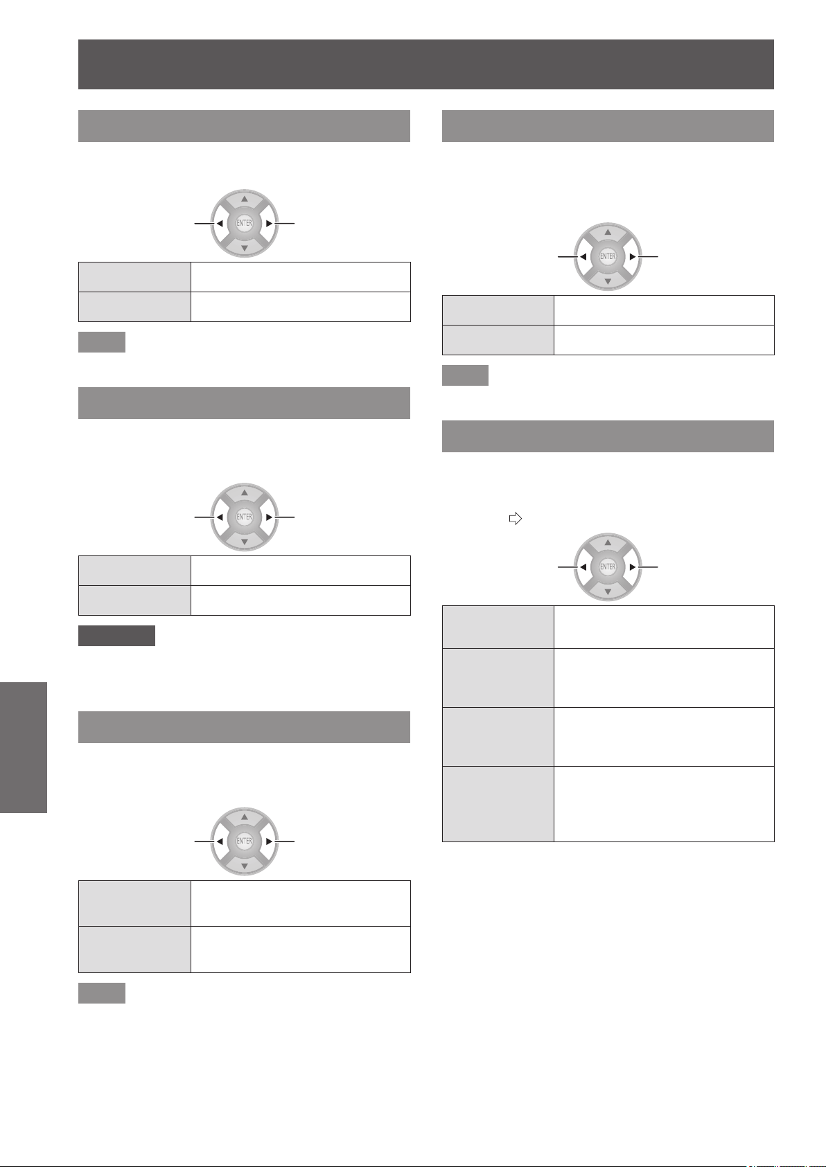
[OPTION] menu
78 -
ENGLISH
Settings
[STARTUP LOGO]
You can switch the Panasonic logo that is displayed
when starting up the projector on/off.
Switch settings Switch settings
[ON] Active
[OFF] Inactive
Note
z
The logo Panasonic is displayed for 15 seconds.
[AUTO SEARCH]
Sets whether to automatically search for terminals
that have an input signal when the projector is turned
on.
Switch settings Switch settings
[ON] Active
[OFF] Inactive
Attention
z
Set this to [ON] under normal circumstances.
z
When no signal is detected, the last used input will be
selected.
[HDMI SIGNAL LEVEL]
If video is not displayed correctly when this projector
is connected to an external device via an HDMI
connection, switch the settings.
Switch settings Switch settings
[NORMAL]
Signal level used by general
external devices
[EXPAND]
Expanded signal level used by
some devices
Note
z
This may not work correctly with some external devices,
and problems such as video not being displayed may
occur.
[FRAME RESPONSE]
Switch this setting when a progressive signal is
input and you wish to reduce the time taken from the
signal being input to the video being displayed on the
screen.
Switch settings Switch settings
[NORMAL] Prioritizes the image quality
[FAST] Prioritizes the frame response
Note
z
[NORMAL] allows higher quality image viewing.
[PROJECTION METHOD]
Set the projection method according to the projector
installation status. Change the projection method if
the screen is displayed upside down or the display is
reversed. (
page 21)
Switch settings Switch settings
[FRONT/DESK]
When setting on a desk/oor and
projecting from the front
[FRONT/
CEILING]
When using the ceiling mount
bracket (optional accessory) and
projecting from the front
[REAR/DESK]
When setting on a desk/oor and
projecting from the rear (using a
translucent screen)
[REAR/
CEILING]
When using the ceiling mount
bracket (optional accessory) and
projecting from the rear (using a
translucent screen)
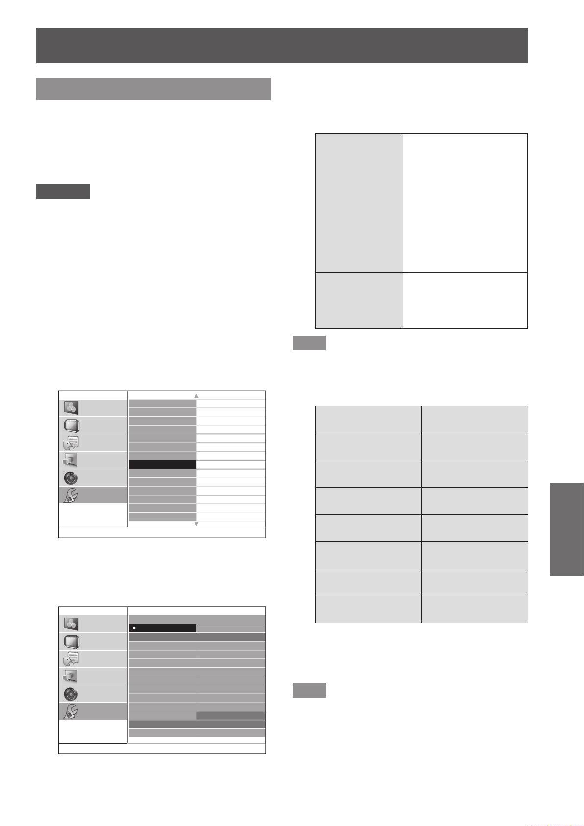
[OPTION] menu
ENGLISH
- 79
Settings
[TRIGGER 1/2 SETTING]
You can set the function for each trigger terminal.
The trigger terminals for this projector are used as
both the input/output terminal for the trigger function
and the output terminal for the external 3D IR
Transmitter (optional accessory). This is selected with
a menu.
Attention
z
You can connect a maximum of two external 3D IR
Transmitter (optional accessory).
z
Make sure the <MAIN POWER> switch of the projector
is turned <OFF> before a cable is connected to or
disconnected from a trigger terminal.
■
[OUTPUT]
In conjunction with projector operation set in the [TRIGGER
1 SETTING]/[TRIGGER 2 SETTING] menu, a trigger
output signal is sent to an external device with a trigger
terminal to enable control.
■
[INPUT]
Receipt of a trigger input signal from an external device
enables control of projector operation setup in the
[TRIGGER 1 SETTING]/[TRIGGER 2 SETTING] menu.
ON-SCREEN DISPLAY
BACK COLOR
STARTUP LOGO
AUTO SEARCH
HDMI SIGNAL LEVEL
FRAME RESPONSE
PROJECTION METHOD
TRIGGER 1 SETTING
TRIGGER 2 SETTING
SLEEP
HIGH ALTITUDE MODE
LAMP POWER
FUNCTION BUTTON
VIERA LINK SETTINGS
BLUE
ON
ON
NORMAL
NORMAL
FRONT/DESK
OFF
OFF
OFF
OFF
NORMAL
PICTURE
POSITION
LANGUAGE
3D SETTINGS
LENS CONTROL
OPTION
1/2
1) Use the ▲▼ buttons to select [TRIGGER
1 SETTING] or [TRIGGER 2 SETTING] and
press the <ENTER> button.
z
The [TRIGGER SETTING] menu is displayed.
TRIGGER
1
SETTING
OFF
OUTPUT
POWER ON
SELECT LENS MEMORY 1
SELECT LENS MEMORY 2
SELECT LENS MEMORY 3
SELECT LENS MEMORY 4
SELECT LENS MEMORY 5
SELECT LENS MEMORY 6
BLANK
DELAY TIME
INPUT
POWER ON/OFF
3D SHUTTER OUT
SELECT 4:3 ASPECT
SELECT 16:9 ASPECT
SELECT S16:9 ASPECT
SELECT JUST ASPECT
SELECT ZOOM ASPECT
SELECT H-FIT ASPECT
SELECT V-FIT ASPECT
RS-232C COMMAND LINK
0 SEC.
BLANK
PICTURE
POSITION
LANGUAGE
3D SETTINGS
LENS CONTROL
OPTION
2) Press the ▲▼◄► buttons to select
the input/output function and press the
<ENTER> button.
z
Function settings
[OFF]
Unable to transmit the
trigger output signal. Does
not function even if trigger
input signal is received.
(Trigger input signal can
be received.)
An external 3D IR
Transmitter (optional
accessory) will not
operate even if
connected.
[3D SHUTTER
OUT]
Select this for connecting
and use of an external 3D
IR Transmitter (optional
accessory).
Note
z
Read the operating instructions for the external 3D IR
Transmitter (optional accessory) when using a 3D IR
Transmitter.
z
Output
[POWER ON]
[SELECT 4:3
ASPECT]
[SELECT LENS
MEMORY 1]
[SELECT 16:9
ASPECT]
[SELECT LENS
MEMORY 2]
[SELECT S16:9
ASPECT]
[SELECT LENS
MEMORY 3]
[SELECT JUST
ASPECT]
[SELECT LENS
MEMORY 4]
[SELECT ZOOM
ASPECT]
[SELECT LENS
MEMORY 5]
[SELECT H-FIT
ASPECT]
[SELECT LENS
MEMORY 6]
[SELECT V-FIT
ASPECT]
[BLANK]
[RS-232C COMMAND
LINK]
When the item which is set in the [TRIGGER
1 SETTING]/[TRIGGER 2 SETTING] menu is
chosen or executed in the projector, 12 V is output
from a trigger terminal.
Note
z
When [AUTO] is selected in the [ASPECT] menu of
[POSITION], video is automatically displayed using either
4:3 or 16:9 aspect ratio depending on the input signal,
so if this aspect ratio matches the settings made in
[TRIGGER 1 SETTINGS] or [TRIGGER 2 SETTINGS]
12 V is output.
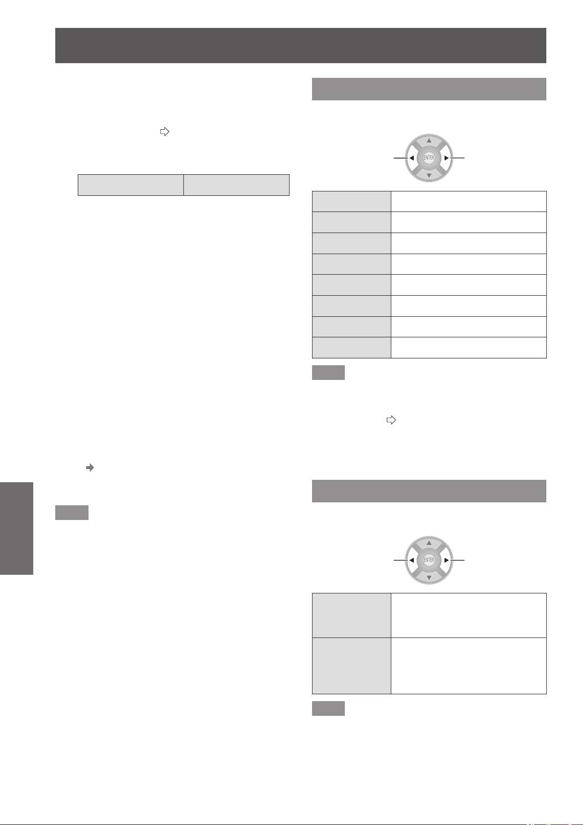
[OPTION] menu
80 -
ENGLISH
Settings
• [BLANK]
When [BLANK] is activated, output is 12 V. If the
setting is released, output is 0 V.
• [RS-232C COMMAND LINK]
Receives commands (
page 103) from external device
and outputs 12 V.
z
Input
[POWER ON/OFF] [BLANK]
• [POWER ON/OFF]
If the trigger input signal from the external device is
changed from 0 V to 12 V, the projector power will be
switched on. And if it is changed from 12 V to 0 V, the
power will be switched off.
• [BLANK]
If the trigger input signal from the external device is
changed from 0 V to 12 V, the screen will go blank. And
if it is changed from 12 V to 0 V, the [BLANK] setting
will be released.
3) Press the ▲▼◄► buttons to move the
cursor to [DELAY TIME]
4) Press the ◄► buttons to set the delay
time for the trigger output signal
z
The delay time can be set to 2, 4, 6, 8, 10, 20, and
30 seconds.
z
It is possible to delay the trigger output signal (12 V)
by the amount of time set. (Only available if trigger
output item is selected.)
E.g.) Select [SELECT 4:3 ASPECT] of the trigger output
function and set the delay time to 10 seconds.
Set the [ASPECT] in the [POSITION] menu to [4:3],
and 12V is output from the trigger port after 10
seconds.
Note
z
You should not use trigger terminal output as the power
source for other devices.
z
The projector will not accept trigger input while preparing
to project after the power has been switched on and
while preparing to shutdown after projection. Input trigger
signals after projection starts or after entering standby
mode.
z
12 V cannot be output from the trigger terminal when the
projector is in standby mode.
[SLEEP]
Set the time for the power to be automatically turned
off.
Switch settings Switch settings
[OFF] Inactive
[60MIN.] Turn power off after 60 minutes
[90MIN.] Turn power off after 90 minutes
[120MIN.] Turn power off after 120 minutes
[150MIN.] Turn power off after 150 minutes
[180MIN.] Turn power off after 180 minutes
[210MIN.] Turn power off after 210 minutes
[240MIN.] Turn power off after 240 minutes
Note
z
The projector automatically enters power off preparation
mode (the power indicator illuminates orange), and then
enters standby mode (the power indicator illuminates or
ashes in red). (
page 28)
z
3 minutes before turn-off, the number of minutes
remaining will be displayed in the lower right corner.
z
If [SLEEP] mode is set to [OFF] mode before the
specied time has elapsed the settings are erased.
[HIGH ALTITUDE MODE]
Set to [ON] when using at locations between 1 400 m
(4 593 ft) and 2 700 m (8 858 ft) above sea level.
Switch settings Switch settings
[OFF]
When using at an altitude of less
than 1 400 m (4 593 ft) above
sea level
[ON]
When using at high altitudes
(between 1 400 m (4 593 ft) and
2 700 m (8 858 ft) above sea
level)
Note
z
The fan rotation and operating noise increases if set to
[ON].
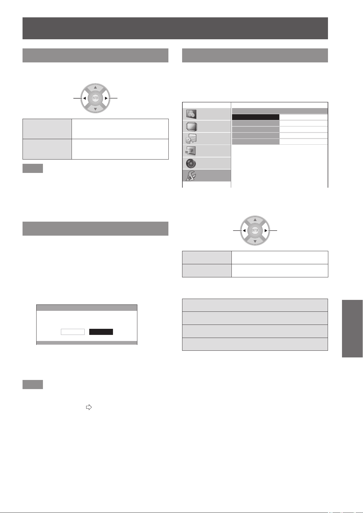
[OPTION] menu
ENGLISH
- 81
Settings
[LAMP POWER]
Switch the lamp intensity according to the usage
environment of the projector and its intended use.
Switch settings Switch settings
[NORMAL]
When higher luminance is
required
[ECO]
When lower luminance is
sufcient
Note
z
The brightness in the [ECO] settings is lowered
enabling saving power and reducing operating noise. It
is recommended that you use the [ECO] setting when
viewing in a place where natural light is blocked and
there is no articial light.
z
When no input signal is detected, the function is disabled.
[FUNCTION BUTTON]
Display the function currently assigned to the
<FUNCTION> button of the remote control. Also,
cancel the assigned function.
■
How to cancel function assignment
1) Press the <ENTER> button.
z
The [FUNCTION BUTTON] conrmation message
is displayed.
FUNCTION BUTTON
FUNCTION BUTTON IS DISABLED.
CANCELOK
2) Select [OK] with the ◄ ► buttons.
3) Press the <ENTER> button.
Note
z
See “Using the <FUNCTION> button” in “Remote
control operation” regarding allocating operations to the
<FUNCTION> button. (
page 34)
[VIERA LINK SETTINGS]
Congure VIERA Link.
Press the <ENTER> button.
z
The [VIERA LINK SETTINGS] conrmation
message is displayed.
VIERA LINK SETTINGS
VIERA LINK
POWER ON LINK
POWER OFF LINK
ENERGY SAVING MODE
UNUSED DEVICE ENERGY SAVE
VERSION : HDAVI Control 5
ON
NO
NO
QUICK START
NO (STAY ON)
PICTURE
POSITION
LANGUAGE
3D SETTINGS
LENS CONTROL
OPTION
■
[VIERA LINK]
Set whether the VIERA Link control is active.
Switch settings Switch settings
[ON] Active
[OFF] Inactive
When [VIERA LINK] is [ON], the following settings can be
made.
[POWER ON LINK]
[POWER OFF LINK]
[ENERGY SAVING MODE]
[UNUSED DEVICE ENERGY SAVE]
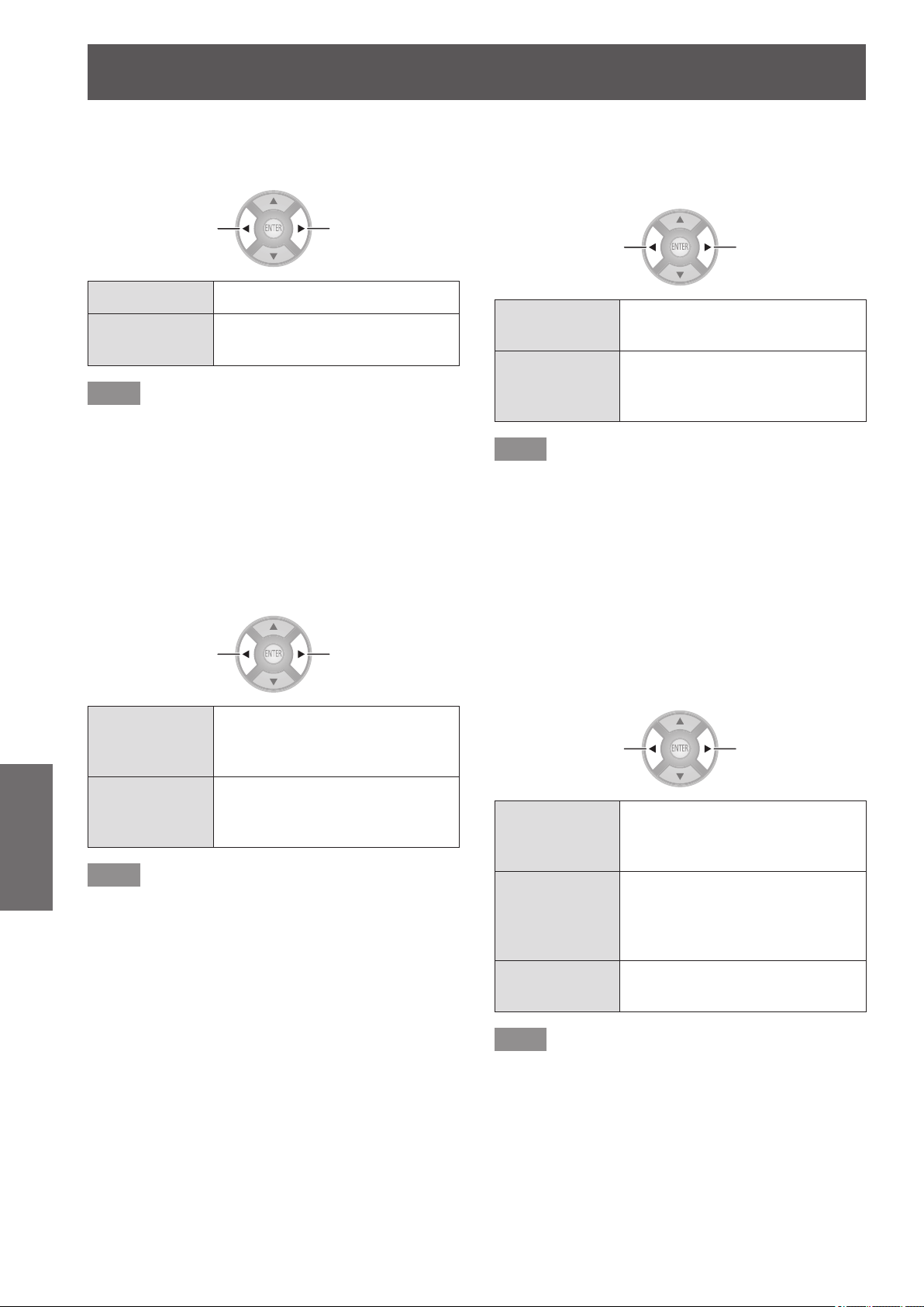
[OPTION] menu
82 -
ENGLISH
Settings
■
[POWER ON LINK]
Specify whether or not to switch the power of the projector
on when it is in standby by operating external devices.
Switch settings Switch settings
[NO] Inactive
[YES]
Switch projector power on along
with external devices
Note
z
Depending on the external device, the projector may
automatically turn on when some functions of the
connected devices are used. (Only in standby)
z
Due to the projector’s characteristics, it takes time
before projection begins. Please be aware that video
may already have started by the time the projector is
operating fully.
■
[POWER OFF LINK]
Specify whether to switch the power off for external devices
when this projector is set to standby.
Switch settings Switch settings
[YES]
Switch the power of external
devices off along with this
projector
[NO]
Do not switch the power of
external devices off along with
this projector
Note
z
This function works even if the projector enters standby
mode automatically through the [SLEEP] function.
z
There are cases where some external devices may
not be switched off depending on their status (currently
recording etc.)
■
[ENERGY SAVING MODE]
Specify whether or not to switch the mode of external
devices to the mode with minimum power consumption
when the projector is set to standby.
Switch settings Switch settings
[QUICK
START]
Do not switch
[SAVE]
Switch the mode of external
devices to the mode with
minimum power consumption
Note
z
This function works when [POWER OFF LINK] is set to
[YES].
z
Depending on the external devices, when the projector
is turned on power consumption may increase even in
[ENERGY SAVING MODE] mode in order to achieve
faster start up.
■
[UNUSED DEVICE ENERGY SAVE]
Specify whether or not to keep the power on for external
devices selected for input and switch the power off for
external devices not selected for input.
If you select [YES (WITH PROMPT)], a message is
displayed before the function operates.
Switch settings Switch settings
[NO (STAY
ON)]
Maintain the power on state of
devices for which input is not
selected
[YES (WITH
PROMPT)]
After a conrmation message is
displayed, devices for which the
input is not selected are set to
standby mode
[YES (NO
PROMPT)]
Devices for which the input is not
selected are set to standby mode
Note
z
This function may not work properly depending on the
external device.
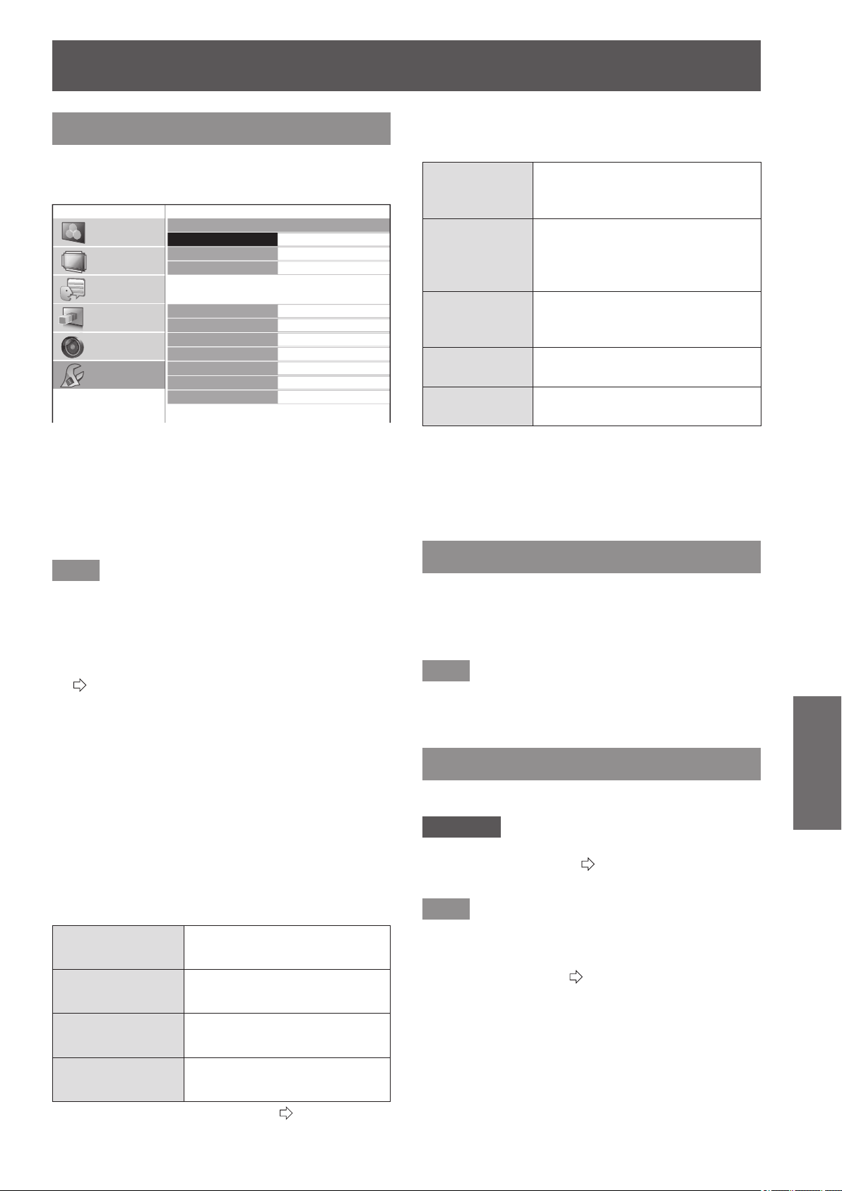
[OPTION] menu
ENGLISH
- 83
Settings
[OTHER FUNCTIONS]
Press the <ENTER> button.
z
The [OTHER FUNCTIONS] menu is displayed.
OTHER FUNCTIONS
FREEZE
BLANK
VIERA LINK
INPUT SELECT
HDMI1 IN
HDMI2 IN
HDMI3 IN
COMPUTER IN
COMPONENT IN
S-VIDEO IN
VIDEO IN
PICTURE
POSITION
LANGUAGE
3D SETTINGS
LENS CONTROL
OPTION
■
[FREEZE]
You can temporarily freeze the projected video
independently of external device playback.
Press the <ENTER> button.
z
Pressing the <RETURN> button cancels the
function.
Note
z
While displaying the frozen image, you can enter the
[AREA SELECT] mode of the [SPLIT ADJUST] menu
by pressing the <ENTER> button. However, when a 3D
signal is being input (including converting 2D to 3D),
transition to [SPLIT ADJUST] is not possible.
For details see [SPLIT ADJUST] in the [PICTURE] menu.
(
page 44)
■
[BLANK]
When the projector is not being used for a brief period,
such as during a break in a meeting or during preparation
for a meeting, the video can be stopped temporarily.
Press the <ENTER> button.
z
Press any button to escape from the blank mode.
■
[VIERA LINK]
You can operate an HDMI-connected device.
Press the <ENTER> button.
z
The [VIERA LINK] menu is displayed.
[VIERA LINK
CONTROL]
Selects the device to operate
and switches input
[HOME THEATER
VOLUME]
Adjusts the theater volume
[HOME THEATER
MUTE]
Mutes the theater
[OPERATE
OTHER DEVICE]
Operates third-party device
z
For details, see “Using VIERA Link”. (
page 96)
■
INPUT SELECT
The input can be switched directly.
[HDMI 1/2/3 IN]
HDMI signal from the device
connected to
HDMI IN 1/HDMI IN 2/HDMI IN 3.
[COMPUTER IN]
RGB signal and
COMPONENT signals (YC
B
C
R
/
YP
B
P
R
) from the device connected
to COMPUTER IN.
[COMPONENT
IN]
COMPONENT signals (YC
B
C
R
/
YP
B
P
R
) from the device connected
to COMPONENT IN.
[S-VIDEO IN]
S-VIDEO signal from the device
connected to S-VIDEO IN.
[VIDEO IN]
VIDEO signal from the device
connected to VIDEO IN.
1) Use the ▲ ▼ buttons to place the cursor
on the input to be switched.
2) Press the <ENTER> button.
z
Switch to the selected input.
[TEST PATTERN]
You can display 5 types of image patterns for
conrmation.
Press the <ENTER> button to switch to the other patterns.
Pressing the <RETURN> button cancels the
function.
Note
z
When 3D is being displayed (including converting 2D to
3D), the [TEST PATTERN] cannot be executed. Perform
the operation after switching to 2D.
[LAMP RUNTIME]
You can check how long the lamp has been used.
Attention
z
When replacing the lamp, follow the “Lamp unit
replacement procedure” (
page 91) and set the runtime
to [0].
Note
z
When the lamp unit has reached the end of its lifespan
the [LAMP RUNTIME] menu will provide the usage
time notication by ashing red and gray. See “When to
replace the lamp unit” (
page 90) about the lifespan.
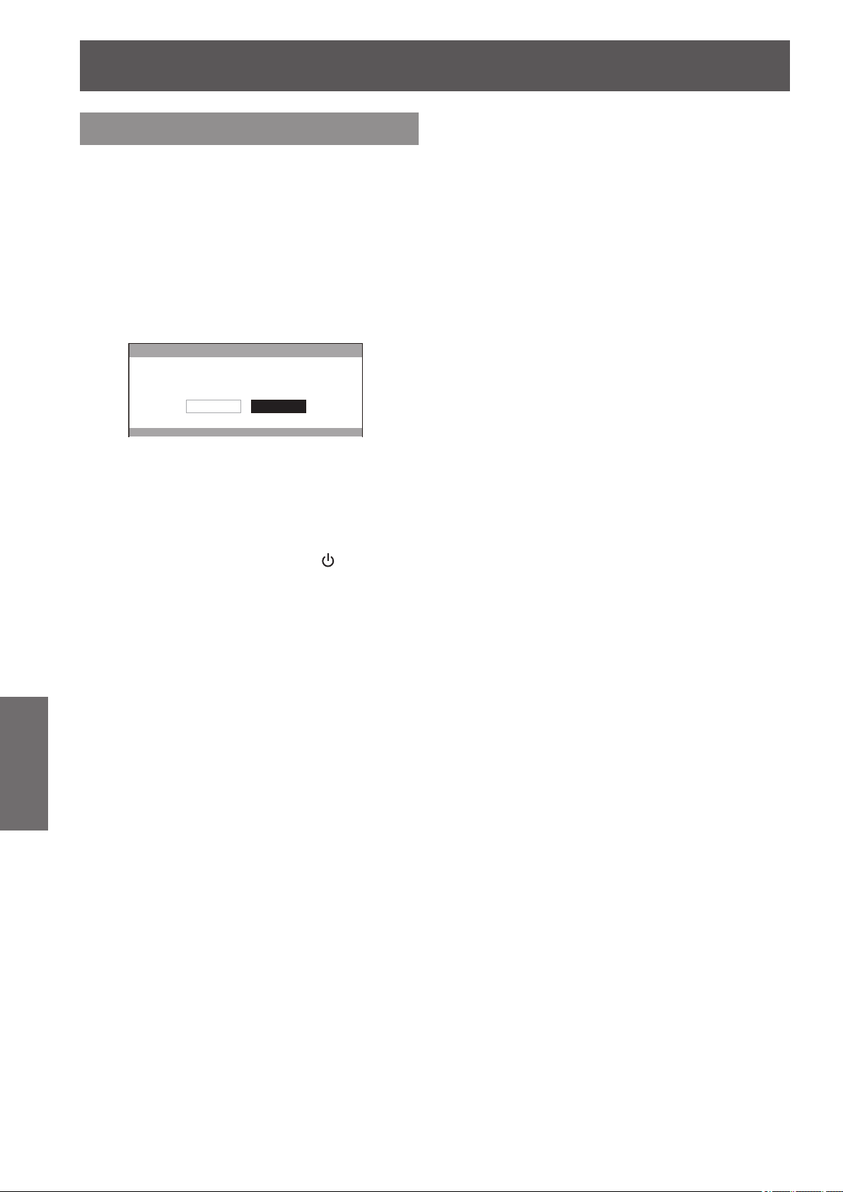
[OPTION] menu
84 -
ENGLISH
Settings
[INITIALIZE ALL]
Return all settings to factory defaults.
When you perform this operation, the projector is set
to the standby state for initialization.
1) Press the ▲▼ buttons to select
[INITIALIZE ALL], and press and hold the
<ENTER> button for three seconds or
more.
z
The [INITIALIZE ALL] conrmation message
appears.
INITIALIZE ALL
INITIALIZE ALL
CANCELOK
2) Press the ◄► buttons to select [OK],
and press the <ENTER> button.
z
The "Initializing …" screen is displayed followed by
the "Turn OFF computer" conrmation screen..
3) Press the <ENTER> button.
z
At this point, all key operations other than the
<ENTER> button and the power <
/ | > button are
disabled.
4) Wait until the power indicator of the
projector <ON (G) / STANDBY (R)> lights
up red or ashes (the fan stops).
5) Turn OFF the power supply by pressing
the <OFF> side of the <MAIN POWER>
switch.
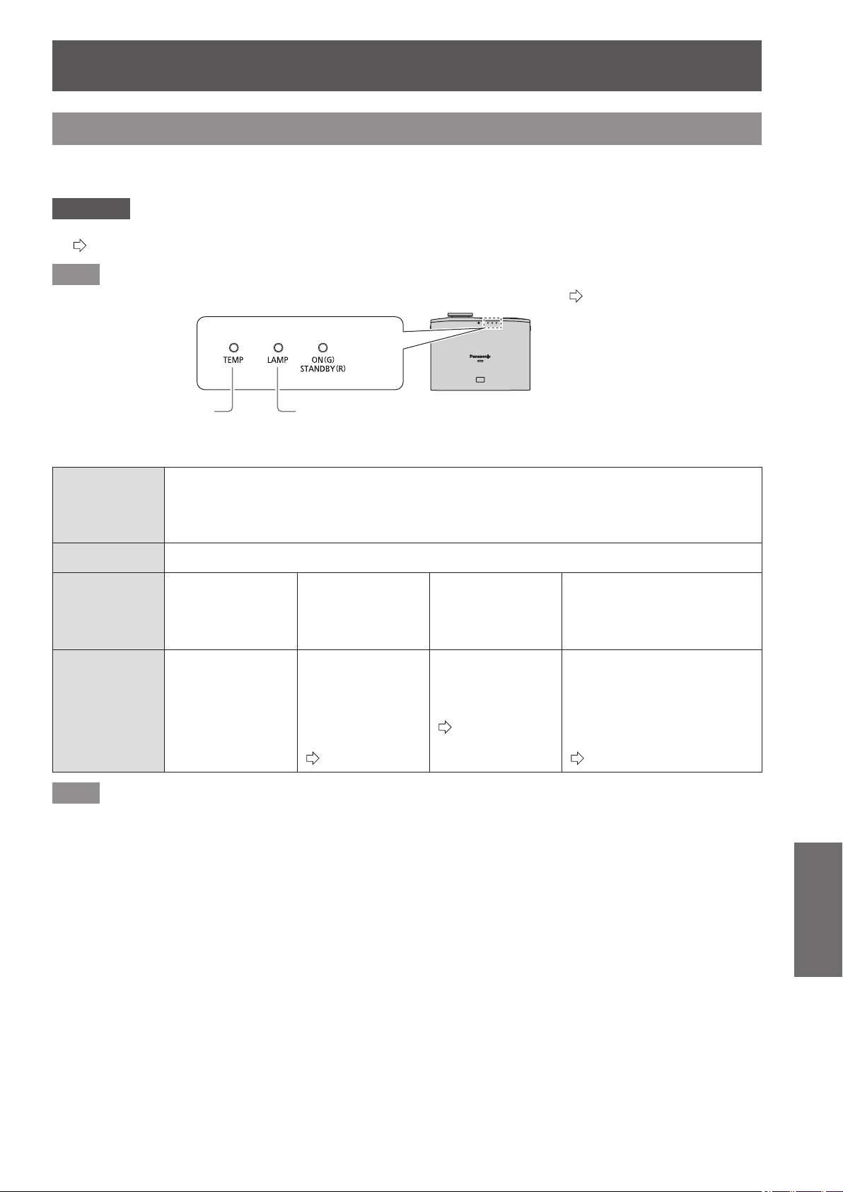
TEMP and LAMP Indicators
ENGLISH
- 85
Maintenance
TEMP and LAMP Indicators
Managing the indicated problems
If a problem should occur with the projector, the lamp indicator <LAMP> and/or temperature indicator <TEMP>
will illuminate or ash. Check the indicator status and deal with problems as follows.
Attention
z
When switching off power to deal with problems, ensure that you follow the procedure in “Switching off the power”.
(
page 30)
Note
z
Check the status of the power supply with the power indicator <ON (G)/STANDBY (R)>. (
page 28)
Lamp indicatorTemperature indicator
■
Temperature indicator <TEMP>
Indicator
status
z
Illuminates red during projection.
(Alert indicating [REFER TO THE “TEMP indicator” SECTION IN THE OPERATION MANUAL.] is
displayed.)
z
Flashing red when power is turned off (projection stops automatically).
Problem The temperature inside and/or outside the projector is abnormally high.
Cause
The air intake and
exhaust ports may
be obstructed.
The room
temperature may
be too high.
The air lter unit
may be excessively
dirty and ventilation
may be poor.
The projector may be being
used at high elevations
(1 400 m (4 593 ft) or more
above sea level).
Solution
Remove object(s)
from the ventilation
ports or clear the
area around the
projector.
Place the projector
in an environment
with temperature
and humidity as
designated in the
specications.
(
page 106)
Clean or replace
the air lter unit.
(
page 87)
The projector can only be
used for two minutes after
turning on. Set [HIGH
ALTITUDE MODE] to [ON]
within two minutes of turning
the projector on.
(
page 80)
Note
z
If the <TEMP> indicator is illuminated or ashes despite taking the actions above, please contact your dealer to have your
projector repaired.
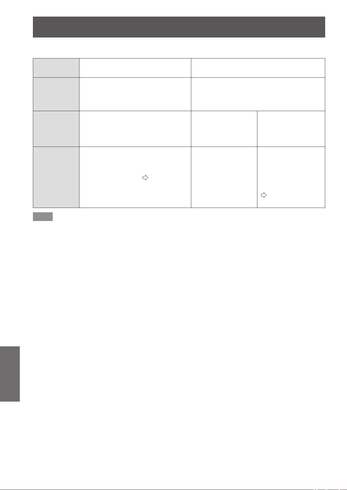
TEMP and LAMP Indicators
86 -
ENGLISH
Maintenance
■
Lamp indicator <LAMP>
Indicator
status
Illuminated red Flashing red
Problem
Time to replace the lamp unit. Illuminates when
the lamp unit has reached its maximum usage
period of 3 800 hours (when [LAMP POWER]
is set to [NORMAL]).
Lamp circuit failure, abnormal function or lamp unit
is damaged.
Cause
A message suggesting lamp replacement
is displayed when power is turned on.
The power may
have been turned on
immediately after being
turned off.
Lamp circuit failure,
abnormal function or
lamp unit is damaged.
Solution Replace the lamp unit.
(
page 91)
Let the lamp unit cool
down and turn on the
power.
Press the <OFF> side
of the <MAIN POWER>
switch to turn off the
power as described
in the “Switching off
the power” procedure
(
page 30)
and contact
your dealer.
Note
z
If the <LAMP> indicator is illuminated or ashes despite taking the actions above, please contact an Authorized Service
Center to have your projector repaired.
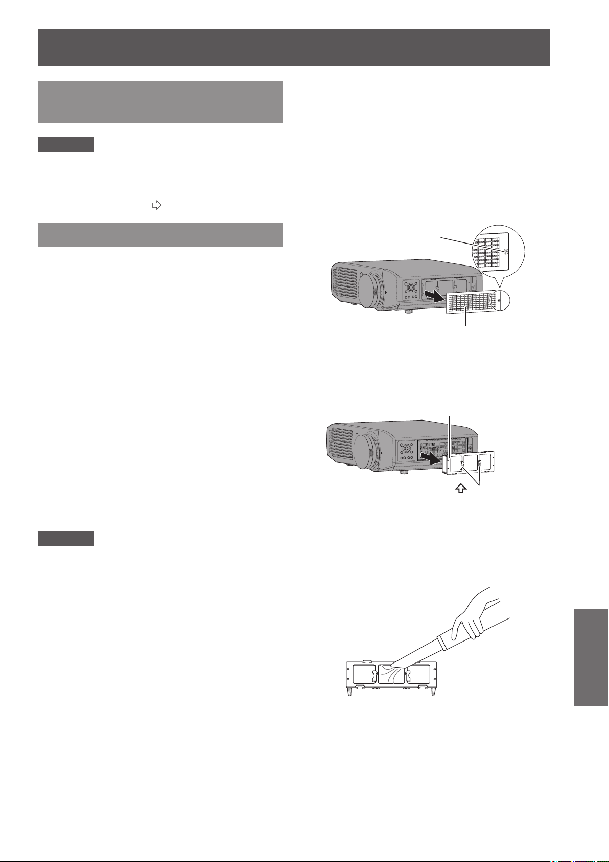
Care and replacement
ENGLISH
- 87
Maintenance
Before cleaning the projector /
replacing components
Attention
z
Turn off the <MAIN POWER> switch and disconnect
the power plug from the wall outlet before cleaning the
projector/replacing components.
z
Follow the “Switching off the power” procedure when
turning off the projector. (
page 30)
Cleaning the projector
■
Cleaning the outer surface of the
projector
Wipe off dirt and dust gently with a soft dry cloth.
z
If it is difcult to remove the dirt, soak a cloth in water,
wring the cloth well and then wipe the projector. Dry
the projector with a dry cloth.
z
Do not use petroleum benzene, thinner, any
alcoholic solvent, or kitchen detergents. Using these
substances may result in changes or damage to the
surface of the projector.
z
When using a chemically treated cloth, follow the
accompanying guidelines.
■
Cleaning the lens surface
If dirt or dust accumulates on the surface of the lens, it will
be enlarged and projected onto the screen.
Wipe dirt and dust from the front of the lens gently with a
clean, soft, and dry cloth.
z
Do not use a uffy rag, or a greasy, wet, or dirty
cloth.
z
Do not rub the lens harshly as this may damage the
surface.
Attention
z
The lens is made of glass. It may break or crack if struck
with a hard object or rubbed harshly. Please be careful
when handling the lamp.
■
Air lter unit
If too much dust accumulates in the air lter the internal
temperature of the projector cannot be maintained at the
normal level. A conrmation message is displayed on the
screen, and at the same time <TEMP> illuminates red. The
power is cut off automatically after a while. Clean the lter
after every 100 hours of usage.
1) Remove the air lter cover.
z
Using a Phillips screwdriver to turn the xing screw
of the air lter cover until loose and remove the
cover.
Air filter cover
Air filter cover fixing
screw
2) Remove the air lter unit.
z
Hold the grips on the air lter unit, and remove it
from the projector.
Air filter unit
Grips (
UP
arrow engraved)
* After removing the air lter unit, remove any large build
ups of dirt or dust in the air lter unit bay and the air
intake port on the projector.
3) Vacuum dirt and dust from the air lter
unit.
z
Do not wash the air lter unit.
Care and replacement

Care and replacement
88 -
ENGLISH
Maintenance
4) Attach the air lter unit to the projector.
z
Attach the air lter unit to the projector using the
reverse of the procedure in 2).
* Insert the air lter unit into the projector in the
direction of the arrow engraved into the air lter
frame (
UP
)
until it clicks into place.
5) Attach the air lter cover, and rmly
tighten the air lter cover xing screw
(one) with a Philips screwdriver.
Attention
z
The air lter unit must always be installed in the projector.
Failure to do so will result in malfunctions due to foreign
materials, such as dust, entering the projector.
z
Do not use water to wash the air lter unit as this
decreases its ability to absorb dust.
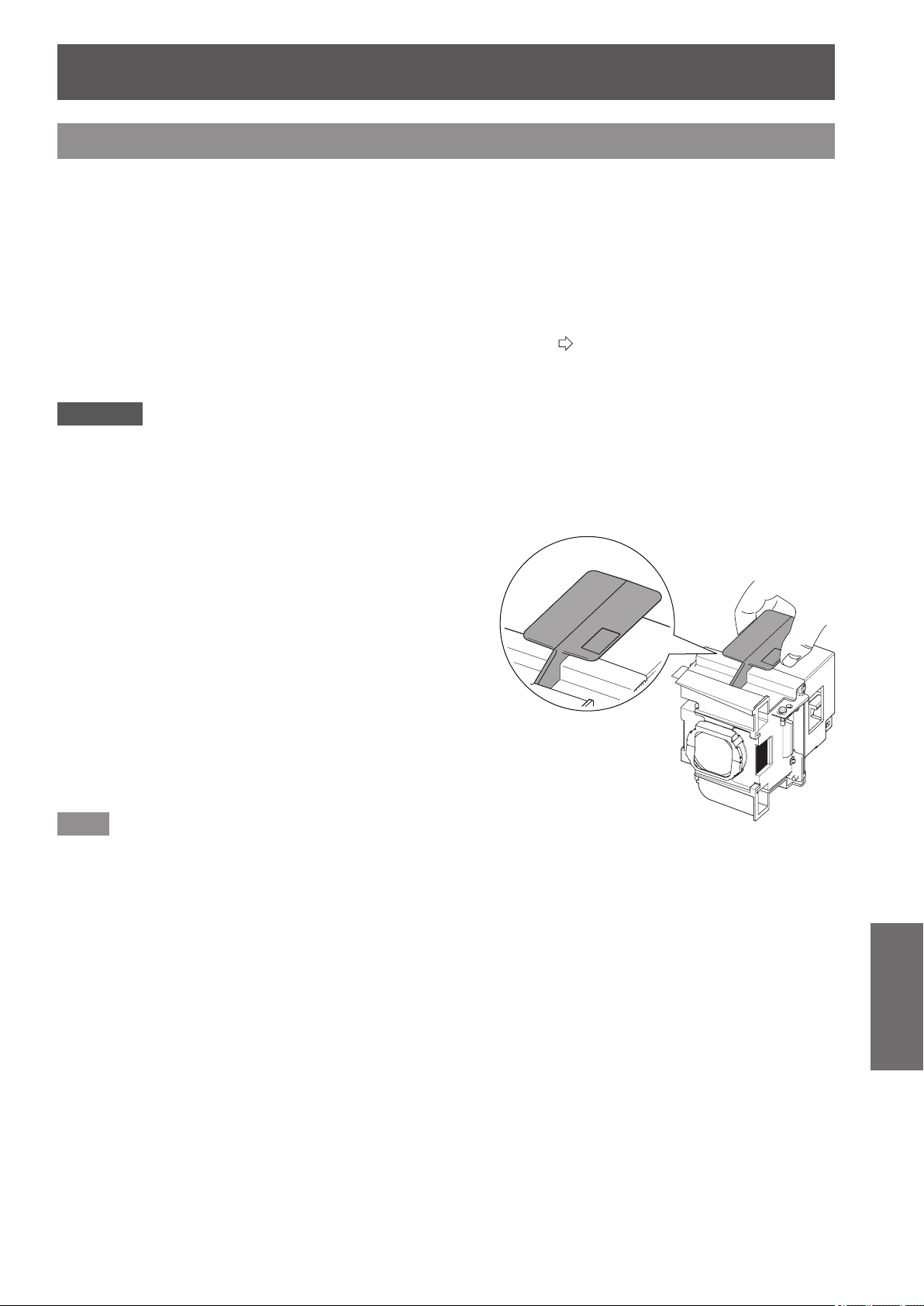
Care and replacement
ENGLISH
- 89
Maintenance
Component replacement
■
Air lter and electrostatic lter
The air lter should be replaced when cleaning is ineffective.
A replacement air lter / electrostatic lter is available separately (service component).
Contact your dealer for the optional air lter and electrostatic lter.
Also, please replace the air lter and electrostatic lter when replacing the lamp unit.
(An air lter and electrostatic lter are included with the [ET-LAA410] replacement lamp unit.)
■
Lamp unit
The lamp unit is a consumable component. See “When to replace the lamp unit” (
page 90) about the lifespan.
Contact your dealer if you wish to purchase a replacement lamp unit (ET-LAA410: Service component).
It is recommended that specialized engineers perform lamp unit replacement. Contact your dealer.
Attention
z
Wait until the lamp unit has cooled sufciently before replacing (wait one hour or longer).
The lamp cover gets very hot, and contact with it can cause burns.
■
Before replacing the lamp unit
z
A Phillips screwdriver is necessary when carrying out
replacement. Hold the screwdriver rmly.
z
The light source lamp is a glass component. If it is hit on a
hard object or dropped, breakage may occur.
Be careful when handling a light source lamp.
z
Do not disassemble or modify the lamp unit.
z
Grip the handle when you remove the lamp unit. Some parts
of the lamp unit are sharpened and may cause injury.
z
The lamp may be ruptured. Care should be taken not to
scatter pieces of the broken lamp glass when replacing the
lamp unit. Pieces of the broken lamp may fall from the lamp
unit especially when the projector is mounted on the ceiling, so
when replacing the lamp unit do not stand directly underneath
it or position your face close to it.
z
The lamp contains mercury. Contact the local government
ofce or distributor for the correct disposal of the old lamp unit.
Note
z
Be sure to use the lamp unit specied.
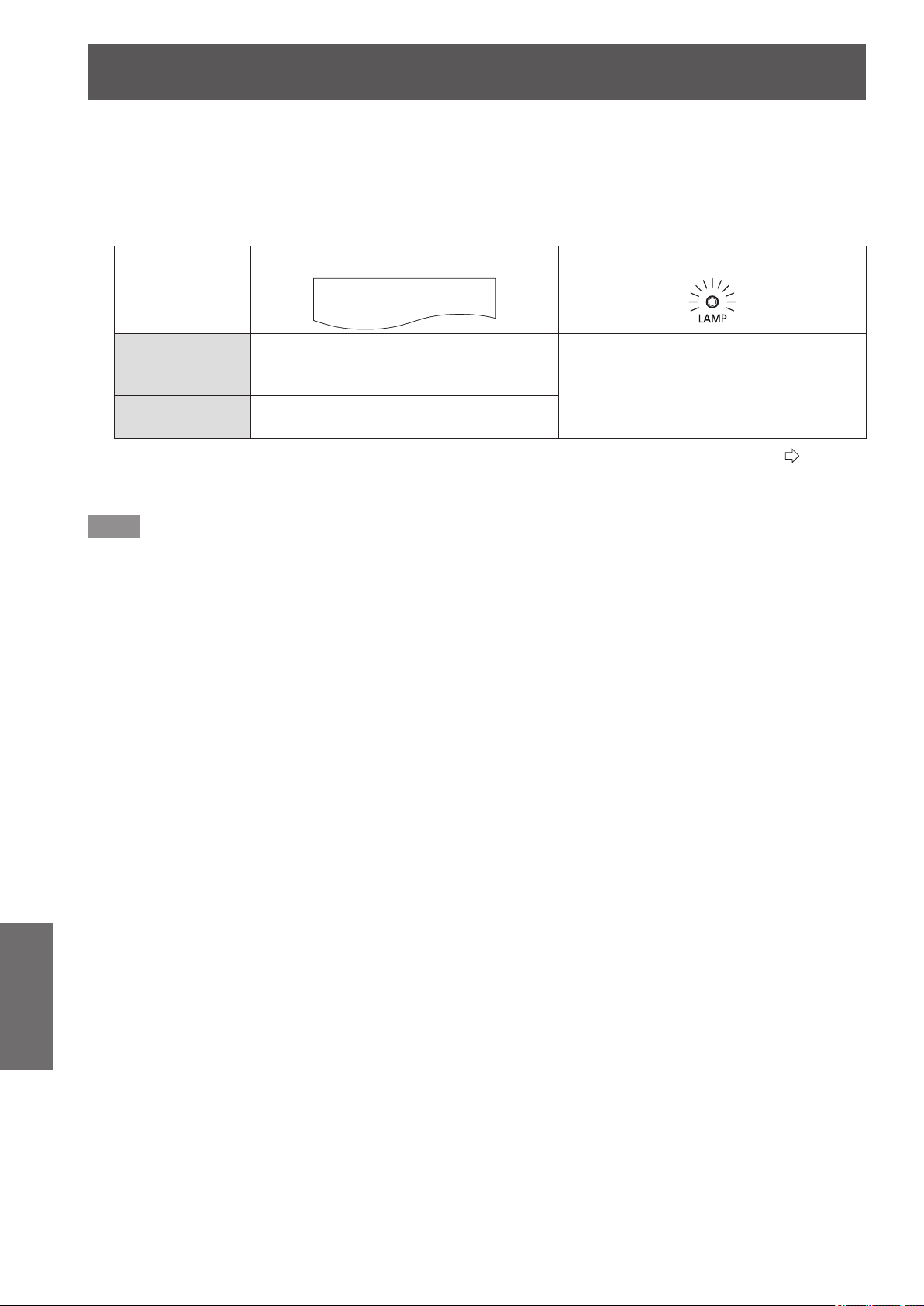
Care and replacement
90 -
ENGLISH
Maintenance
■
When to replace the lamp unit
The lamp unit is a consumable component. Brightness decreases according to duration of usage, so periodical replacement
of the lamp unit is necessary. A rough estimate for the usage period is 4 000 hours, but depending on the characteristics of
individual lamps, usage conditions, periods of continuous use, and environmental conditions etc., the lamp may cease to
illuminate prior to reaching 4 000 hours of use. It is recommended that you prepare a spare lamp unit in advance.
As the risk of the lamp to cracking increases after 4 000 hours the lamp automatically turns off.
On screen
REPLACE LAMP
Lamp indicator
Over 3 800
*1
hours
The message is displayed for 30 seconds.
If you press any button within the 30
seconds, the message disappears.
Illuminates red, including when in standby
mode.
Over 4 000
*1
hours
The message is displayed until you press
any button.
*1: This is the time value for when the lamp is used with [LAMP POWER] in the [OPTION] menu set to [NORMAL] (
page 81).
Differs from the actual usage time displayed in [LAMP RUNTIME] of the [OPTION] menu. This time increases greatly when
[LAMP POWER] is set to [ECO].
Note
z
Setting [LAMP POWER] to [ECO] results in decreased brightness but the lamp may be used for longer.
z
The usage period of 4 000 hours is a rough estimate and is not guaranteed.
When the lamps are turned on and off frequently, the lamp replacement cycle is shortened. The usage environment affects
the lamp replacement cycle.
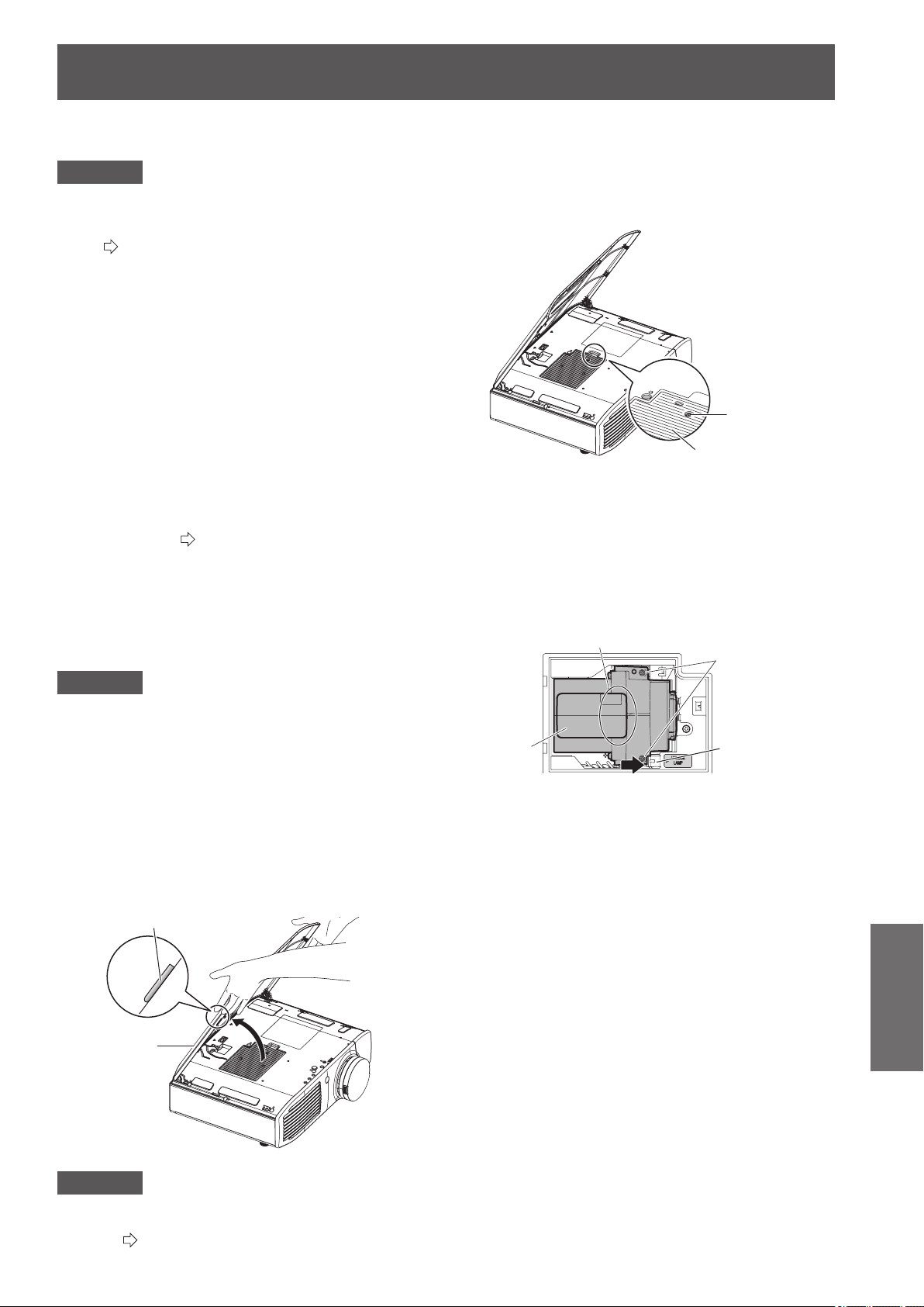
Care and replacement
ENGLISH
- 91
Maintenance
■
Lamp unit replacement procedure
Attention
z
Once a lamp unit has exceeded its lifespan of 4 000
hours (when [LAMP POWER] is set to [NORMAL]) the
projector can only be used for 10 minutes after turning
on. (
page 90)
z
Perform steps 20) to 23) of the procedure within 10
minutes.
z
If the projector is installed on the ceiling, do not carry out
any replacement procedure directly underneath the lamp
unit and keep your face away from the unit.
z
Do not open the top cover except when replacing the
lamp unit.
z
Do not switch the power on while the top cover is
opened.
z
Always replace the air lter and electrostatic lter
whenever replacing the lamp unit.
z
Install the lamp unit and the lamp cover securely.
1) Press the <OFF> side of the <MAIN
POWER> switch to turn off the power as
described in the “Switching off the power”
procedure (
page 30), remove the power
plug from the power outlet, and then after an
hour or more, check if the area surrounding
the lamp unit has cooled down.
2) Remove the video cable connected to the
connecting terminal.
Attention
z
If you open the top panel fully, it may come into contact
with connectors such as the video cable which may result
in breakage of the video cable. Before opening the top
panel, be sure to remove the connected video cables,
etc.
3) Hold the protrusions at the front corner
of the top cover of the projector and
push up to open.
* When the projector is mounted on the ceiling, stand
at the lens side of the projector when opening/
closing the top cover.
Top cover
Protrusion
Attention
z
Be careful not to open the top panel too far. For what
to do if the top panel comes off, see ”Attaching the top
cover” (
page 93).
4) Use a Philips screwdriver to unscrew
the lamp cover xing screw (one) until
it becomes loose, and then remove the
lamp cover.
* Slowly remove the lamp cover from the projector.
Lamp cover
Lamp
cover fixing
screw
5) Use a Phillips screwdriver to unscrew the
lamp unit xing screws (2 screws) until
loose.
6) Hold the handle of the lamp unit and with
the lamp unit
lock held in the direction of
the black arrow, carefully pull it out of the
projector unit in a vertical motion.
モ
Lamp unit fixing
screws
Handle
Lamp unit lock
7) Replace the new lamp unit while making
sure that the direction of insertion is
correct. Press the top of the lamp unit
downwards and make sure the unit is
installed securely. Tighten the lamp unit
xing screws (2 screws) securely with a
Phillips screwdriver.
z
Press down on the A part rmly when inserting the
lamp unit.
8) Mount the lamp cover, and tighten the lamp
cover xing screw (one screw) securely with
a Phillips screwdriver.
9) Close the top cover of the projector.
z
Close the top cover using the reverse of the
procedure in 3), and press the center of the top
cover.
10) Reconnect the video cable disconnected
in 2) to the connecting terminal.
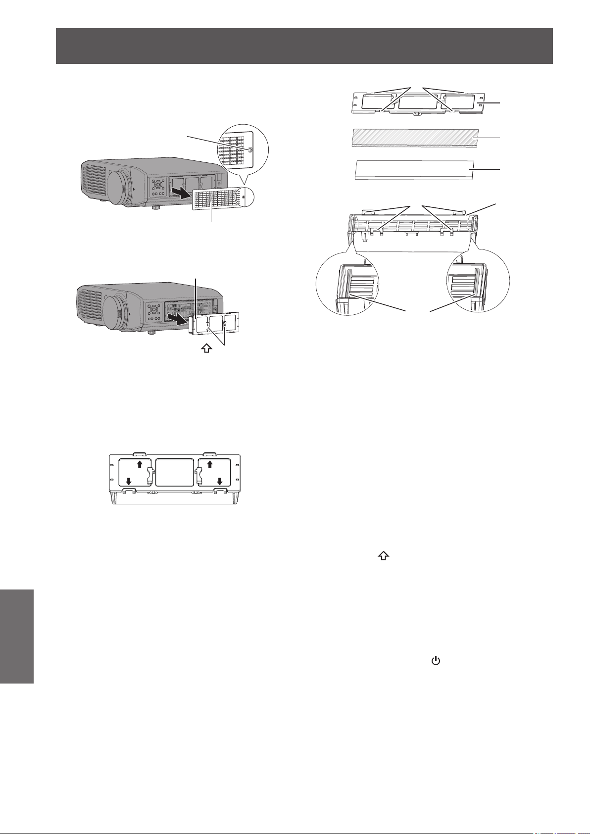
Care and replacement
92 -
ENGLISH
Maintenance
11) Remove the air lter cover.
z
Using a Phillips screwdriver to turn the xing screw
of the air lter cover until loose and remove the
cover.
Air filter cover
Air filter cover fixing
screw
12) Remove the air lter unit.
z
Hold the grips on the air lter unit, and remove it
from the projector.
Air filter unit
Grips (
UP
arrow engraved)
* After removing the air lter unit, remove any large
build ups of dirt or dust in the air lter unit bay and
the air intake port on the projector.
13) Press the protrusions of air lter unit
removed from the projector in the
direction of the black arrow and remove
the air lter frame.
14) Replace the air lter/electrostatic lter.
z
Replace the air lter and electrostatic lter in the air
lter unit with new ones.
* Ensure you attach the electrostatic lter and air
lter in the correct order.
Air filter case
Air filter (black)
Electrostatic filter
(white)
Protrusions
Ribs
Air filter frame
Catches
15) Assemble the air lter unit.
z
First insert the electrostatic lter (white) into the
center of the case ensuring that its edges do not
ride on top of the ribs, and then insert the air lter
(black) so that its four corners are within the case
before attaching the air lter frame.
* Take care so that the air lter does not get caught
between the air lter frame and the case.
* Align the catches and protrusions on the air lter
case and air lter frame when assembling the
air lter unit. When attaching the air lter frame,
ensure that the 4 catches are properly aligned with
the protrusions on the air lter case and they have
clicked into place.
16) Attach the air lter unit to the projector.
z
Attach the air lter unit to the projector using the
reverse of the procedure in 12).
* Insert the air lter unit into the projector in the
direction of the arrow engraved into the air lter
frame (
UP
)
until it clicks into place.
17) Attach the air lter cover, and rmly
tighten the air lter cover xing screw
(one) with a Philips screwdriver.
18) Insert the power plug into a power outlet,
and press the <ON> side of the <MAIN
POWER> switch to turn on the power.
19) Press the power <
/|> button on the
projector or on the remote control to
start video projection.
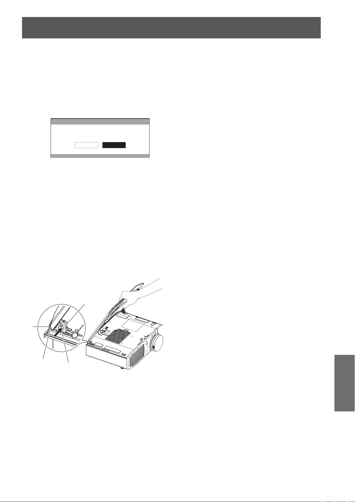
Care and replacement
ENGLISH
- 93
Maintenance
20) Press the <MENU> button to display the
menu screen and select [OPTION] with
the ▲▼ buttons.
21) Press the <ENTER> button and select
[LAMP RUNTIME] with the ▲▼ buttons.
22) Hold the <ENTER> button down for 3
seconds.
z
The conrmation message is displayed.
LAMP RUNTIME
LAMP RUNTIME RESET.
CANCELOK
23) Select [OK] with the ◄ ► buttons and
then press the <ENTER> button.
z
LAMP RUNTIME is reset to “0”, and the projector
powers off. After a short while, the projector enters
standby mode.
■
Attaching the top cover
Hold the top cover as shown in the
diagram below, align the hinge with the
support, and while pushing the arm in the
direction of the arrow (towards the inner
side of the projector), push it into the
groove.
Arm
Groove
Hinge
Support
Troubleshooting
94 -
ENGLISH
Maintenance
Troubleshooting
Re-conrm these points.
See the relevant page for details.
Problem Cause Page
Power does not turn
on.
z
The power cord may not be connected.
z
The <MAIN POWER> switch is turned <OFF>.
z
The wall outlet may not be supplying electricity.
z
The circuit breakers may have tripped.
z
<TEMP> indicator or <LAMP> indicator is illuminated or ashes.
z
The lamp unit may not have been installed correctly.
28
29
—
—
85, 86
91
No picture appears.
z
The signal input source may not be connected to a terminal properly.
z
The input selection setting may not be correct.
z
The [BRIGHTNESS] adjustment setting may be at the minimum setting.
z
The external device connected to the projector may not be functioning correctly.
z
The [BLANK] function may be in use.
z
The lens cover may still be attached to the lens.
26
34
40
—
83
19
The picture is fuzzy.
z
The lens focus may not have been set correctly.
z
The projector may not be at the correct distance from the screen.
z
The lens may be dirty.
z
The projector may be over tilted.
73
22
19
22
The color is pale or
grayish.
z
[COLOR] and [TINT] may not be adjusted correctly.
z
The device connected to the projector may not be adjusted correctly.
40
—
The remote control
does not work.
z
The batteries may have run out.
z
The batteries may not have been inserted correctly.
z
The remote control signal receiver on the projector may be obstructed.
z
The remote control may be out of the range of operation.
z
Fluorescent lights may be interfering.
z
A 3D IR Transmitter may be interfering.
—
18
18
18
—
70
The picture does not
display correctly.
z
[TV-SYSTEM] and [RGB/YC
B
C
R
] or [RGB/YP
B
P
R
] are not selected correctly.
z
There may be a problem with the VCR or other signal source.
z
A signal which is not compatible with the projector is being input.
57, 58
—
—
Picture from a
computer
does not appear.
z
The cable may be too long. (Cable must be less than 10 m (32'10") in length.)
z
The external video output from a personal computer may not be correct.
(You may be able to change the external output settings by pressing the [Fn] +
[F3] or [Fn] + [F10] keys simultaneously. The actual method varies depending on
the type of computer; refer to the documentation provided with your computer for
further details.)
—
—
Video from HDMI
compatible device
does not appear or it
appears jumbled.
z
The HDMI cable is not fully inserted.
z
Turn the power for the projector and the external device off and on.
z
A signal which is not compatible with the projector is being input.
27
28
100
3D video is disrupted
while viewing a 3D
video.
z
The 3D Eyewear may be out of battery. If you are using a rechargeable 3D
Eyewear, charge the battery of the 3D Eyewear. If you are using a disposable
battery for 3D Eyewear, replace the battery.
—
* If the projector still does not work correctly after checking the points above, contact your dealer.
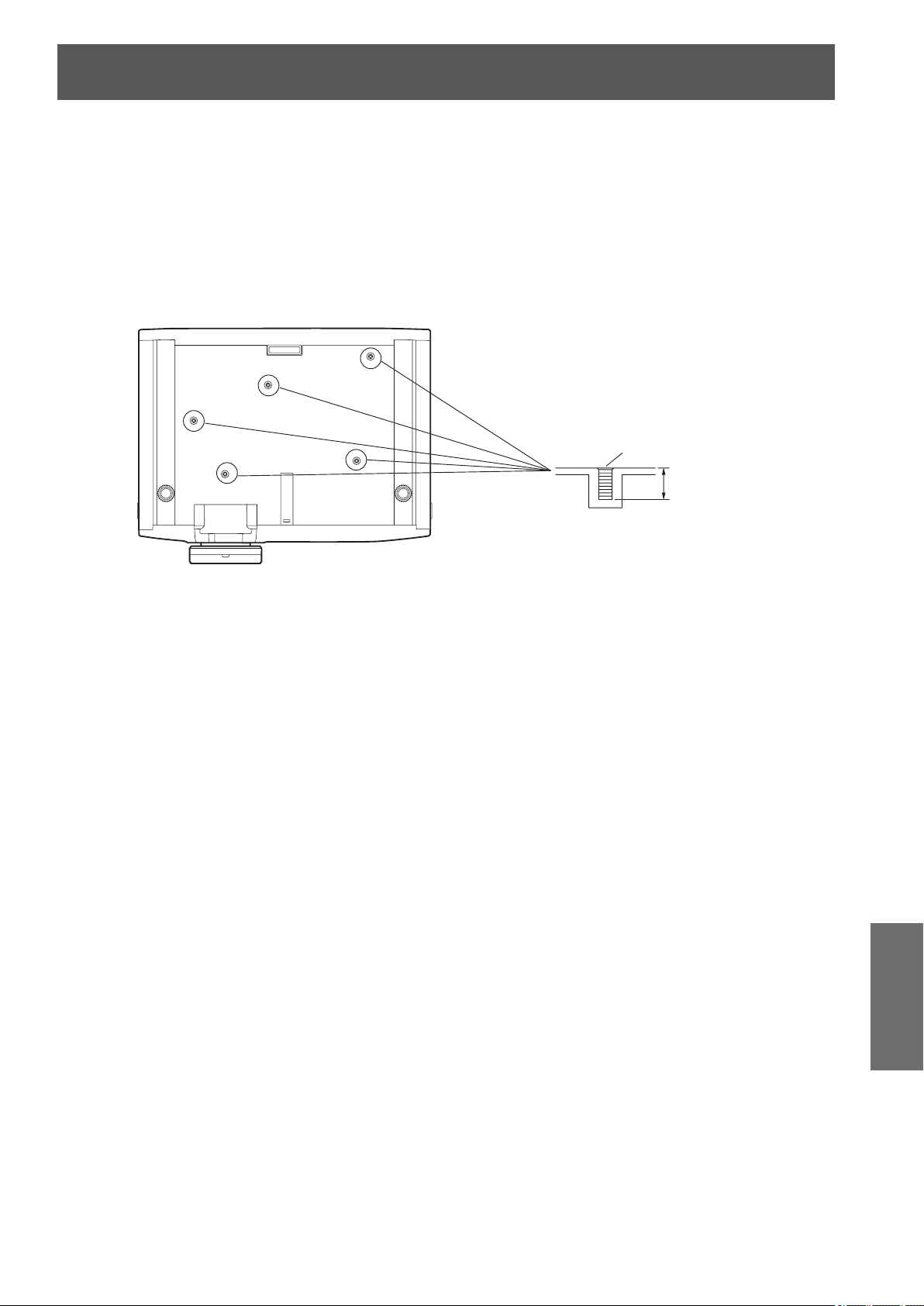
Ceiling mount bracket safeguards
ENGLISH
- 95
Maintenance
Ceiling mount bracket safeguards
z
When mounting the projector on the ceiling, use the Panasonic specied ceiling mount bracket (model no.: ET-PKA110H (for
high ceilings) and ET-PKA110S (for low ceilings)).
z
Installation work of the ceiling mount bracket should only be carried by a qualied technician.
z
Even during the guarantee period, the manufacturer is not responsible for any hazard or damage caused by using a ceiling
mount bracket which is not purchased from an authorized distributors, or environmental conditions.
z
Unused ceiling mount brackets should be removed promptly by a qualied technician.
z
Be sure to use a torque driver. Do not use an electrical screwdriver or an impact screwdriver.
z
See the installation instructions of the ceiling mount bracket for details.
z
The model number of accessories and optional accessories is subject to change without notice.
9 mm (11/32")
M4 × 0.7
Model No. of ceiling mount bracket: ET-PKA110H (for high ceiling)
ET-PKA110S (for low ceiling)
Bottom view
Torque: 1.25 ± 0.2 N·m
Holes for ceiling mount bracket
attachment screws
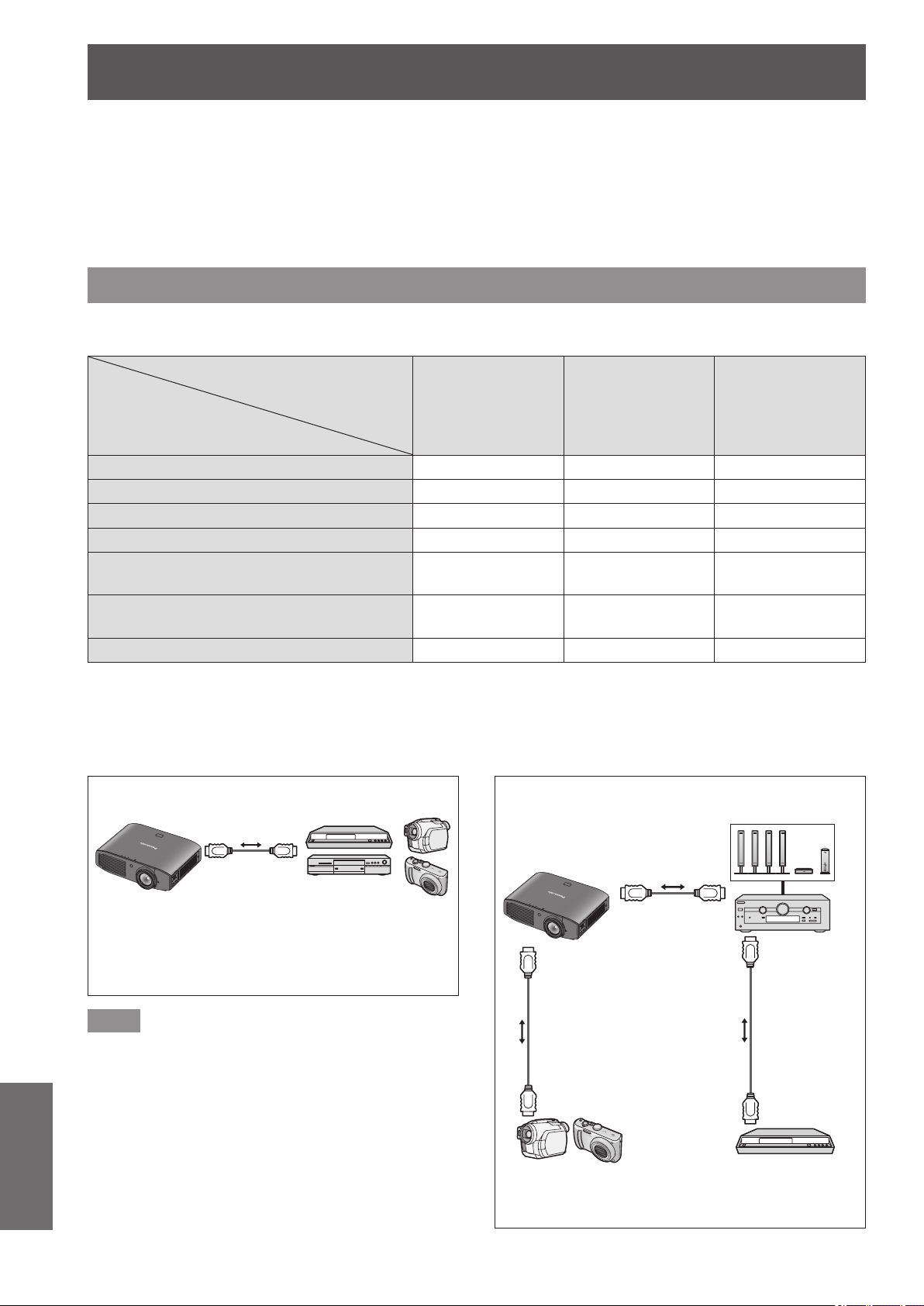
Using VIERA Link
96 -
ENGLISH
Appendix
Using VIERA Link
VIERA Link (HDAVI Control) connects projector and the equipment with VIERA Link function, and enables easy
control of the home theater equipment using the projector remote control.
z
This projector supports “HDAVI Control 5” function.
However, the available features depends on the connected device’s version of HDAVI Control. Please conrm the
connected device’s version of HDAVI Control.
z
Even with devices from other companies, if it is HDMI specication CEC compatible, there are cases where same function
can be used.
Summary of VIERA Link features
■
VIERA Link (HDMI connection only)
Connected device
Feature
DIGA Recorder
with
VIERA Link
function
DVD Player/
Blu-ray Disk Player
with
VIERA Link
function
HD Camcorder/
LUMIX Camera
with
VIERA Link
function
Easy playback
*1
○ ○ ○
[POWER ON LINK] (
page 82) ○ ○ ○
[POWER OFF LINK] (
page 82) ○ ○ ○
[ENERGY SAVING MODE] (
page 82) ○
*3
○
*3
○
[UNUSED DEVICE ENERGY SAVE]
(
page 82)
○
*2
○
*2
○
Control the menu of the connected device
by projector remote control (
page 98)
○
*2
○
*2
○
*2
Speaker control — — —
*1 : When [POWER ON LINK] (
page 82) is [YES], the input of this projector is automatically switched when playback on
external devices such as a DIGA begins.
*2 : Available with a device which has “HDAVI Control 2” or later function.
*3 : Available with a device which has “HDAVI Control 4” or later function.
Note
z
Do not use a cable other than an HDMI High Speed
cable that conforms to HDMI standards.
z
When connecting the projector and a “VIERA Link”
compatible device, connect to the HDMI 1/2/3 input
terminal.
z
With regards to Panasonic products other than this
projector, check the manual for the device to be
connected regarding description for “VIERA Link”.
z
VIERA Link can only be used with one display (projector,
TV, etc).
Connection
DIGA Recorder/DVD Player/
Blu-ray Disc theater/Blu-ray Disc Player/
Player theater/HD Camcorder/
LUMIX Camera with
VIERA Link function
HD Camcorder/
LUMIX Camera with
VIERA Link function
DIGA Recorder with
VIERA Link function
HDMI
cable
HDMI
cable
Amplier with
VIERA Link
function
Speaker system
HDMI cable
Using an amplier
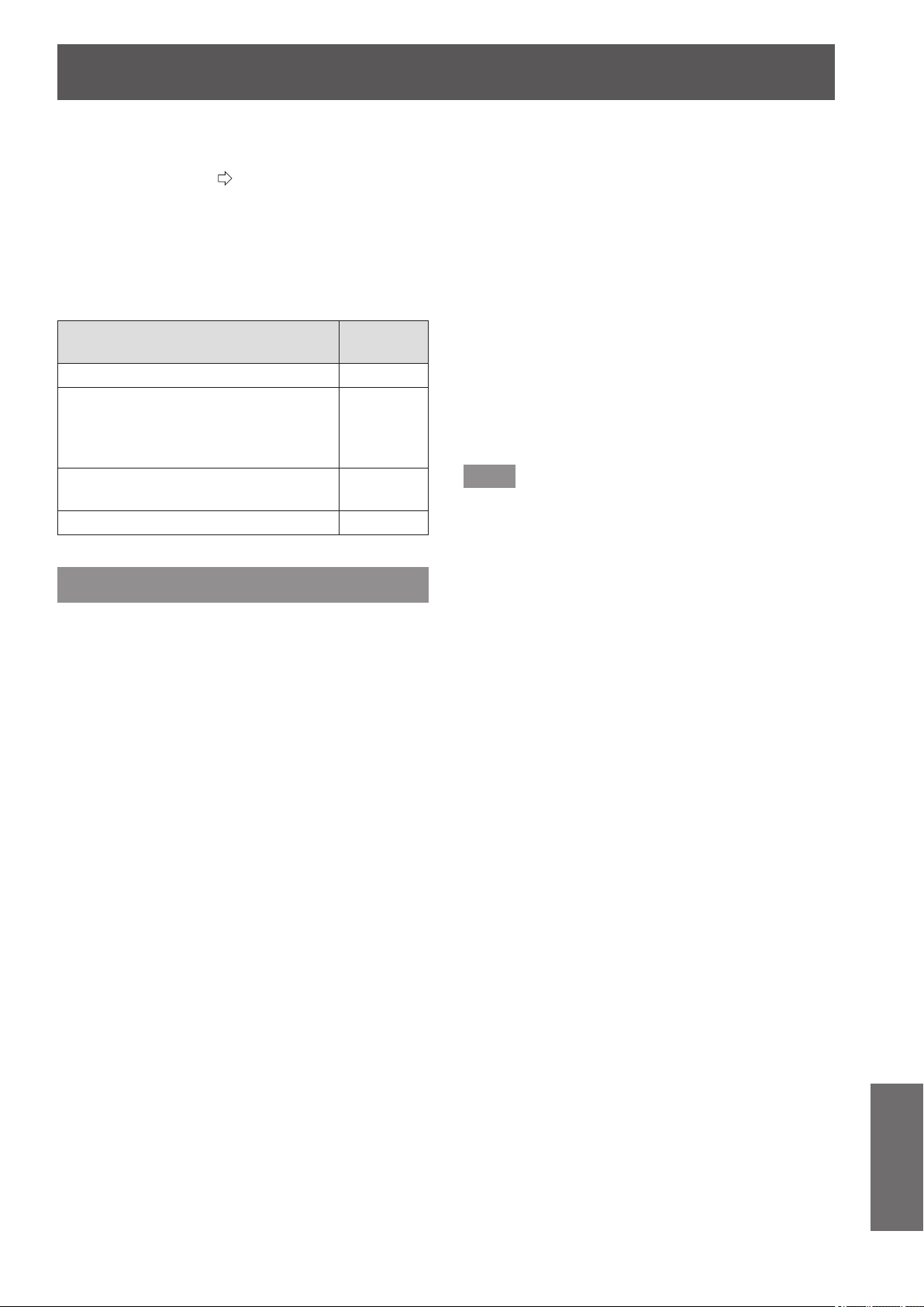
Using VIERA Link
ENGLISH
- 97
Appendix
■
VIERA Link Control of compatible
equipment
“Using [VIERA LINK]” (
page 98)
z
Table below displays maximum number of compatible
equipment that can be controlled by VIERA Link Control.
This includes connections to equipment already
connected to the projector.
For example, DIGA Recorder connected to Amplier
which is connected to the projector via an HDMI cable.
Type of the equipment
Maximum
number
Recorder (DIGA Recorder, etc.) 3
Player (DVD Player, Blu-ray Disc
Player, HD Camcorder, LUMIX Camera,
Digital Camera, Player theater, Blu-ray
Disc theater, etc.)
3
Audio system (Player theater, Blu-ray
Disc theater, Amplier, etc.)
1
Tuner (Set top box, etc.) 4
VIERA Link “HDAVI Control”
Connections to the equipment (DIGA Recorder, HD
Camcorder, Player theater, Amplier, etc.) with HDMI
cables allow you to interface them automatically.
These features are limited to models incorporating
“HDAVI Control” and “VIERA Link”.
z
Some functions are not available depending on the
equipment’s version of HDAVI Control.
Please conrm the connected equipment’s version of
HDAVI Control. But some functions will not be able to
perform even if the versions are the same.
z
VIERA Link “HDAVI Control”, based on the control
functions provided by HDMI which is an industry standard
known as HDMI CEC (Consumer Electronics Control), is
a unique function that we have developed and added.
As such, its operation with other manufacturers’
equipment that supports HDMI CEC cannot be
guaranteed.
z
Please refer to individual manuals for other
manufacturers’ equipment supporting Link function.
z
About applicable Panasonic equipment, consult your
local Panasonic dealer.
■
Preparations
z
Use fully wired HDMI compliant cable. Non-HDMI-
compliant cables cannot be utilized.
z
Set up the connected equipment.
Switch the connected equipment on.
Set [POWER ON LINK] in the setup menu.
(Please read the manual of the equipment for these
setup.)
z
Set up the projector.
Switch the projector on.
Set the input mode to [HDMI 1 IN], [HDMI 2 IN]
or [HDMI 3 IN], and make sure that an image is
displayed correctly.
Select [VIERA LINK SETTINGS] in the [OPTION]
menu.
If the [VIERA LINK] is set to [ON], you need to select
[OFF] rst, and then switch to [ON] again to activate
the [ON] setting.
Note
z
This setup should be done each time when the following
conditions occur:
- When using for the rst time
- When adding or reconnecting equipment
- When changing setup
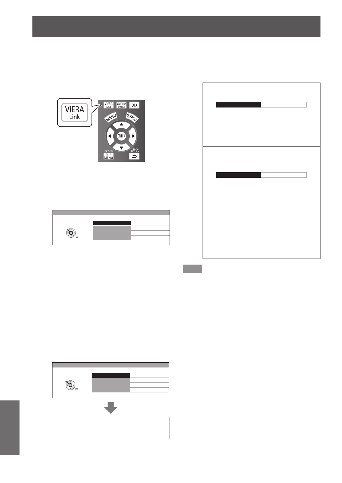
Using VIERA Link
98 -
ENGLISH
Appendix
■
Using [VIERA LINK]
You can control some functions of the connected device
with the controls or remote control of this projector.
z
If operation is not possible, check the settings of the
device.
z
For details on operating an external device, see the
manual of the relevant device.
Press the <VIERA Link> button.
Alternatively, select [VIERA LINK] from
[OTHER FUNCTIONS] in the [OPTION]
menu, and then press the <ENTER>
button.
z
The [VIERA LINK] menu is displayed.
VIERA LINK CONTROL
HOME THEATER VOLUME
HOME THEATER MUTE
OPERATE OTHER DEVICE
RECORDER
VIERA LINK
RETURN
SELECT
ENTER
●
Access and operate the menu of the
equipment
1) Select [VIERA LINK CONTROL] with
the ▲▼ buttons.
2) Select the type of the device to be
connected with the ◄► buttons.
3) Press the <ENTER> button.
(RECORDER / PLAYER / HOME THEATER /
CAMCORDER / LUMIX / DIGITAL CAMERA / OTHER)
z
[HOME THEATER] is a system that includes
the projector, an audio output device, and a
video output device.
z
[OTHER] indicates tuner (such as the set top
box)
VIERA LINK CONTROL
HOME THEATER VOLUME
HOME THEATER MUTE
OPERATE OTHER DEVICE
RECORDER
VIERA LINK
RETURN
SELECT
ENTER
The menu of the accessed device
appears.
(The input mode switches automatically.)
4) Use the menu of the device.
z
You can use the controls of the projector as
well as the buttons on the remote control. (The
functions that you can use depend on the
connected device.)
If you access a device other than a VIERA
Link device
VIERA LINK CONTROL RECORDER 1
The type of the connected device is
displayed.
You can access the menu of the device, but
cannot use it. Use the remote control of the
device to operate it.
If multiple recorders or players are connected
You can connect up to three recorders or
players at the same time.
VIERA LINK CONTROL RECORDER 1
Recorder 1 – 3 / Player 1 – 3
Devices of the same type connected to the
HDMI terminals (1/2/3) on this projector
are registered in an order starting from the
smallest number.
For example, if two recorders are connected
to HDMI 2 and HDMI 3 respectively, the
recorder connected to HDMI 2 is displayed
as [RECORDER 1], and the recorder
connected to HDMI 3 is displayed as
[RECORDER 2].
Note
z
Some operations may not be available depending on
the device. In this case, use its own remote control to
operate the device.
(The colored buttons operations, such as changing the
date of TV program for Blu-ray Disc Recorder cannot be
controlled by the projector remote control.)
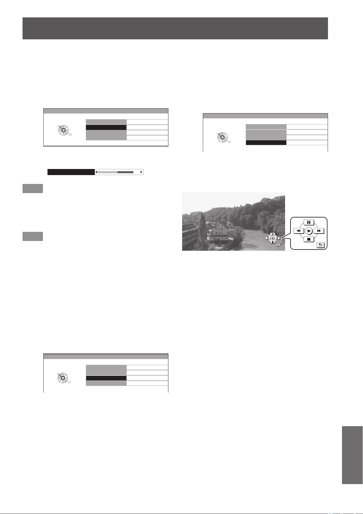
Using VIERA Link
ENGLISH
- 99
Appendix
●
[HOME THEATER VOLUME]
You can adjust the volume of the theater speaker with the
projector remote control.
z
If the volume cannot be adjusted, check the settings
of the device.
1) Select [HOME THEATER VOLUME] with
the ▲▼ buttons.
VIERA LINK CONTROL
HOME THEATER VOLUME
HOME THEATER MUTE
OPERATE OTHER DEVICE
RECORDER
VIERA LINK
RETURN
SELECT
ENTER
2) Press the <ENTER> button.
z
The volume adjustment bar appears.
HOME THEATER VOLUME
64
Note
z
The design of the volume adjustment bar may differ
depending on the connected device.
3) Press the ◄► buttons to adjust the
volume of the device.
Note
z
The speaker functions may not work properly depending
on the connected device.
z
The image or sound may not be available for the rst few
seconds after the input mode is switched.
z
HDAVI Control 5 is the latest Panasonic standard (current
as of September, 2012) for HDAVI Control compatible
devices.
●
[HOME THEATER MUTE]
You can mute theater speakers using the projector remote
control.
z
If you cannot mute the speakers, check the settings
of the device.
1) Select [HOME THEATER MUTE] with
the ▲▼ buttons.
VIERA LINK CONTROL
HOME THEATER VOLUME
HOME THEATER MUTE
OPERATE OTHER DEVICE
RECORDER
VIERA LINK
RETURN
SELECT
ENTER
2) Press the <ENTER> button.
z
Press the <ENTER> button again to cancel the
mute.
●
[OPERATE OTHER DEVICE]
When displaying videos using HDMI input from a third party
external device that supports VIERA Link, you can display
the remote control screen and control the external device
with the projector remote control.
1) Select [OPERATE OTHER DEVICE] with
the ▲▼ buttons.
VIERA LINK CONTROL
HOME THEATER VOLUME
HOME THEATER MUTE
OPERATE OTHER DEVICE
RECORDER
VIERA LINK
RETURN
SELECT
ENTER
2) Press the <ENTER> button.
z
A remote control image appears on the screen.
Use this image to operate the device.
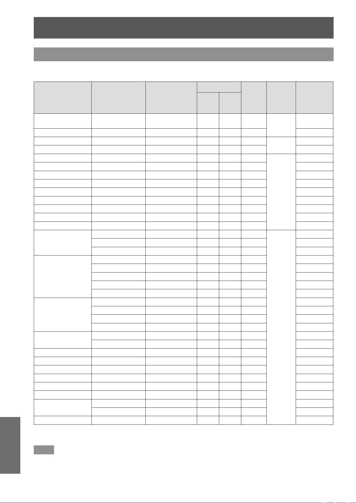
Technical information
100 -
ENGLISH
Appendix
List of compatible signals
The following table species the types of signals compatible with the projectors.
Format: V: VIDEO, S: S VIDEO, R: RGB, Y: YC
B
C
R
/YP
B
P
R
, H: HDMI
Mode SIGNAL MODE
Display
resolution
(dots)
*1
Scanning frequency
Dot clock
frequency
(MHz)
Format
Plug
and play
compatible
HDMI
H
(kHz)
V
(Hz)
NTSC/NTSC 4.43/
PAL-M/PAL60
— 720 × 480i 15.7 59.9 —
V/S
—
PAL/PAL-N/SECAM — 720 × 576i 15.6 50.0 — —
525i (480i) 480i 720 × 480i 15.7 59.9 13.5
R/Y
—
625i (576i) 576i 720 × 576i 15.6 50.0 13.5 —
525p (480p) 480p 720 × 483 31.5 59.9 27.0
R/Y/H
○
625p (576p) 576p 720 × 576 31.3 50.0 27.0 ○
750 (720)/60p 720/60p 1 280 × 720 45.0 60.0 74.3 ○
750 (720)/50p 720/50p 1 280 × 720 37.5 50.0 74.3 ○
1 125 (1 080)/60i 1 080/60i 1 920 ×1 080i 33.8 60.0 74.3 ○
1 125 (1 080)/50i 1 080/50i 1 920 ×1 080i 28.1 50.0 74.3 ○
1 125 (1 080)/24p 1 080/24p 1 920 ×1 080 27.0 24.0 74.3 ○
1 125 (1 080)/60p 1 080/60p 1 920 ×1 080 67.5 60.0 148.5 ○
1 125 (1 080)/50p 1 080/50p 1 920 ×1 080 56.3 50.0 148.5 ○
VGA
VGA60 640 × 480 31.5 59.9 25.2
R
—
VGA75 640 × 480 37.5 75.0 31.5 —
VGA85 640 × 480 43.3 85.0 36.0 —
SVGA
SVGA56 800 × 600 35.2 56.3 36.0 —
SVGA60 800 × 600 37.9 60.3 40.0 —
SVGA72 800 × 600 48.1 72.2 50.0 —
SVGA75 800 × 600 46.9 75.0 49.5 —
SVGA85 800 × 600 53.7 85.1 56.3 —
XGA
XGA60 1 024 × 768 48.4 60.0 65.0 —
XGA70 1 024 × 768 56.5 70.1 75.0 —
XGA75 1 024 × 768 60.0 75.0 78.8 —
XGA85 1 024 × 768 68.7 85.0 94.5 —
MXGA
MXGA70 1 152 × 864 64.0 70.0 94.2 —
MXGA75 1 152 × 864 67.5 74.9 108.0 —
1 280 × 720 1 280 × 720/60 1 280 × 720 44.8 59.9 74.5 —
1 280 × 768 1 280× 768/60 1 280 × 768 47.8 59.9 79.5 —
1 280 × 800 1 280 × 800/60 1 280 × 800 49.7 59.8 83.5 —
SXGA SXGA60 1 280 × 1 024 64.0 60.0 108.0 —
SXGA+ SXGA+60 1 400 × 1 050 65.2 60.0 122.6 —
WXGA+ WXGA+60 1 440 × 900 55.9 59.9 106.5 —
1 920 ×1 080
1 920 ×1 080/60 1 920 × 1 080
*2
66.6 59.9 138.5 —
1 920 ×1 080/50 1 920 × 1 080 55.6 49.9 141.5 —
WUXGA WUXGA60RB 1 920 × 1 200
*2
74.0 60.0 154.0 —
*1 : The “i” displayed after the resolution indicates an interlaced signal.
*2 : VESA CVT-RB (Reduced Blanking) compatible.
Note
z
The number of display dots for the PT-AE8000U display is 1 920 x 1 080.
A signal with a different resolution will be projected after converting the resolution to match the projector display.
z
When interlaced signals are connected, icker may occur on the projected image.
Technical information
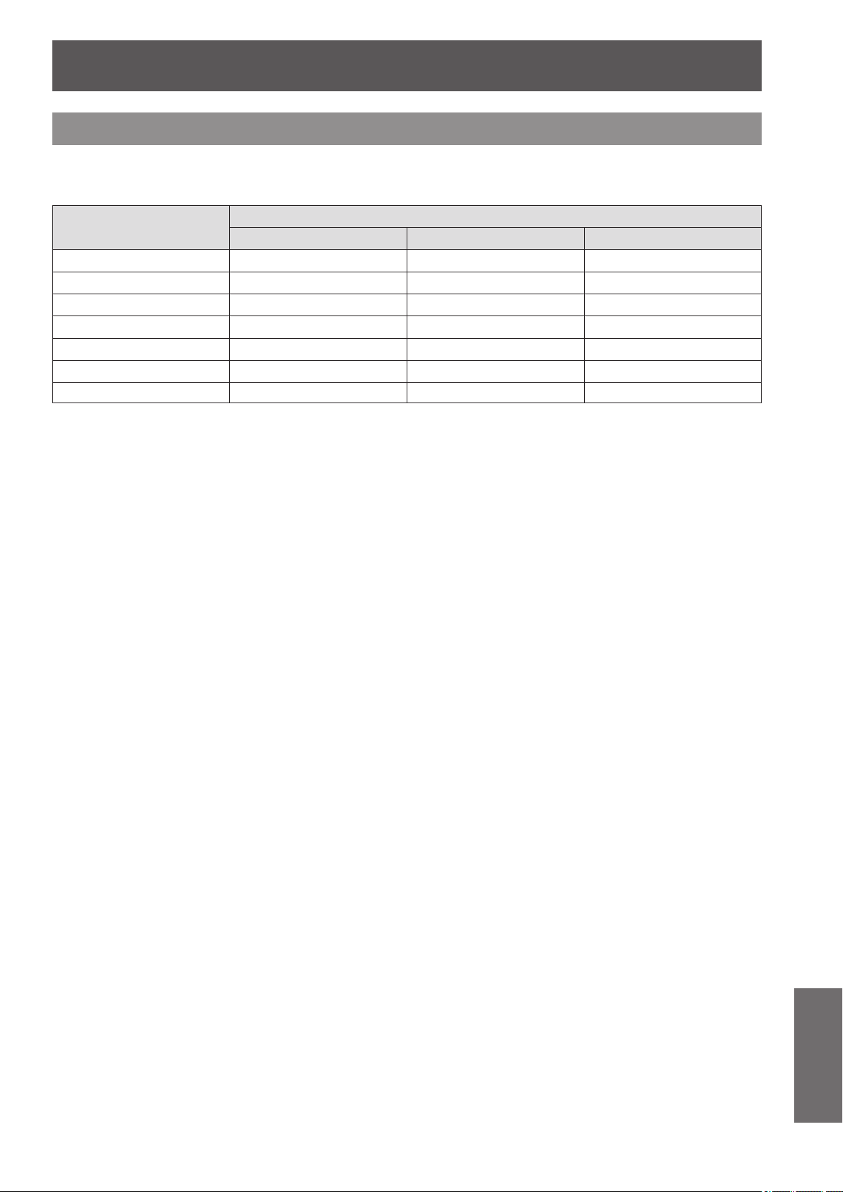
Technical information
ENGLISH
- 101
Appendix
Supported 3D video signal list
When [3D INPUT FORMAT] is set to [AUTO], the 3D signals supported by this projector are the HDMI signals in
the table below.
Mode
Format of 3D video signals
FRAME PACKING SIDE BY SIDE TOP AND BOTTOM
750 (720)/60p
○
*
○ ○
*
750 (720)/50p
○
*
r
○
*
1 125 (1 080)/60i —
○
*
—
1 125 (1 080)/50i —
○
*
—
1 125 (1 080)/24p
○
*
○ ○
*
1 125 (1 080)/60p —
○
—
1 125 (1 080)/50p —
r
—
*: Indicates a 3D mandatory format signal that meets the HDMI standards.
r
: 3D display is possible when [3D INPUT FORMAT] is set to [SIDE BY SIDE].
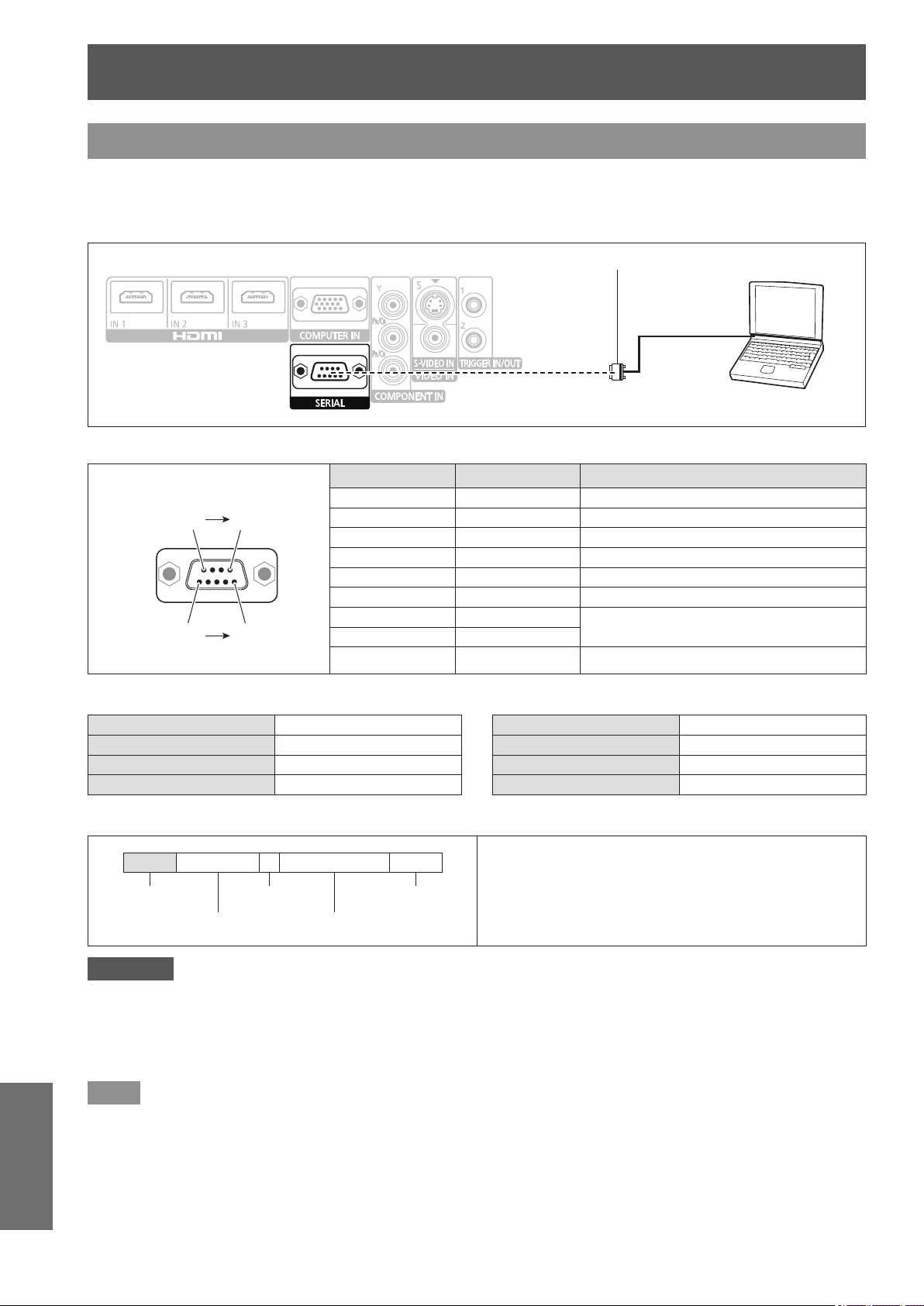
Technical information
102 -
ENGLISH
Appendix
Serial terminal
The serial port on the connector panel of the projector conforms to the RS-232C interface specication, so the
projector can be controlled by a personal computer connected to this port.
■
Connection
Serial terminal (female)
D-sub 9 pin (male)
Computer
■
Pin assignments and signal names
D-Sub 9 Pin (external view)
(6)
(1)
(9)
(5)
Pin No. Signal name Contents
(1) — NC
(2) TXD Transmitted data
(3) RXD Received data
(4) — NC
(5) GND Earth
(6) — NC
(7) RTS
Connected internally
(8) CTS
(9) — NC
■
Communication settings
Signal level RS-232C Character length 8 bits
Sync. method Asynchronous Stop bit 1 bit
Baud rate 9 600 bps X parameter None
Parity None S parameter None
■
Basic format
STX Command : Parameter ETX
Start byte
(02h)
1 byte
End
(03h)
3 bytes 1 byte - 4 bytes
Data streaming from the computer will start with STX,
and proceed to command, parameter and end with
ETX.
Parameters can be added as necessary.
Attention
z
The projector cannot receive any command for 10 seconds after the lamp is switched on. Wait 10 seconds before sending
a command.
z
If sending multiple commands, check that a response has been received from the projector for one command before
sending the next.
z
When a command which does not require parameters to be sent, a colon (:) is not required.
Note
z
If an incorrect command is sent, the ER401 command will be sent from the projector to the personal computer.
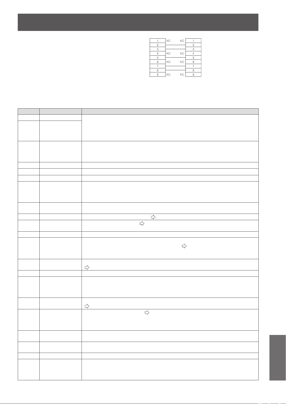
Technical information
ENGLISH
- 103
Appendix
■
Cable specications
(When connected to a personal computer)
■
Control commands
Commands available when controlling this projector from a computer are as follows.
<Operation commands>
Command
Control contents Remarks
PON POWER ON In standby mode, all commands other than the PON command are ignored.
The PON command is ignored during lamp on control.
z
If a PON command is received while the cooling fan is operating after the lamp has
switched off, the lamp is not turned back on unless approximately 85 seconds have
passed in order to protect the lamp.
POF POWER OFF
IIS
SWITCH
INPUT
Parameters
CP1 = COMPONENT IN SVD = S-VIDEO IN
VID = VIDEO IN HD1 = HDMI 1 IN HD2 = HDMI 2 IN HD3 = HDMI 3 IN
RG1 = COMPUTER IN
OMN MENU Displays the main menu.
OEN ENTER Activates the selected items in the menu mode.
OBK RETURN Returns to the previous menu or escaping from the menu mode.
OCU
OCD
OCL
OCR
Navigation buttons
(▲▼◄►)
OCU = ▲ cursor OCD = ▼ cursor
OCL = ◄ cursor OCR = ► cursor
OLE LENS
Displays the test patterns for adjusting [ZOOM/FOCUS].
([RETURN] or [MENU] when nishing)
OST DEFAULT Resets to the factory default setting. (
page 33)
OFZ FREEZE
Freezes the projected screen. (
page 83)
0 = OFF, 1 = ON
FC1 FUNCTION BUTTON Activates the function allocated to the <FUNCTION> button of the remote control.
OSH BLANK
Turns off the projection temporarily.
Sends the command to switch between ON and OFF. (
page 83)
Do not rapidly switch between ON/OFF.
While the BLANK function is ON, it is switched OFF when any command is received.
OVM PICTURE
Activates the [PICTURE] menu. Send the command to switch menu items.
(
page 40)
OMM MEMORY LOAD Displays the [MEMORY LOAD] menu.
OWM WAVEFORM
Parameter
0 = OFF 1 = FULL SCAN(Y) 2 = FULL SCAN(R) 3 = FULL SCAN(G)
4 = FULL SCAN(B) 5 = SINGLE LINE SCAN(Y) 6 = SINGLE LINE SCAN(R)
7 = SINGLE LINE SCAN(G) 8 = SINGLE LINE SCAN(B)
VS1 ASPECT
Switches the aspect ratio. Aspect ratio is switched each time this command is sent.
(
page 61)
VPM PICTURE MODE
Switches the [PICTURE MODE]. (
page
40)
Parameter
NOR = NORMAL DYN = DYNAMIC 709 = REC709 DCN = D-CINEMA
CN1 = CINEMA1 CN2 = CINEMA2 GM1 = GAME
DPA PICTURE ADJUST
Displays the individual adjustment screen of the [PICTURE] menu operated immediately before
this operation.
DCM
COLOR
MANAGEMENT
Displays the [COLOR MANAGEMENT] menu.
OVL VIERA LINK Displays the [VIERA LINK] menu.
OSM SUB MENU
Displays the SUB MENU of the connected equipment, when [VIERA LINK SETTING] - [VIERA
LINK] is [ON], and the "VIERA Link" compatible device and CEC-compatible equipment of other
manufacturers is connected. For details on the CEC-compatible equipment of other manufacturers,
see page 97.
1
2
3
4
5
6
7
8
9
NC
NC
NC
NC
NC
NC
NC
NC
1
2
3
4
5
6
7
8
9
Projector PC (DTE)
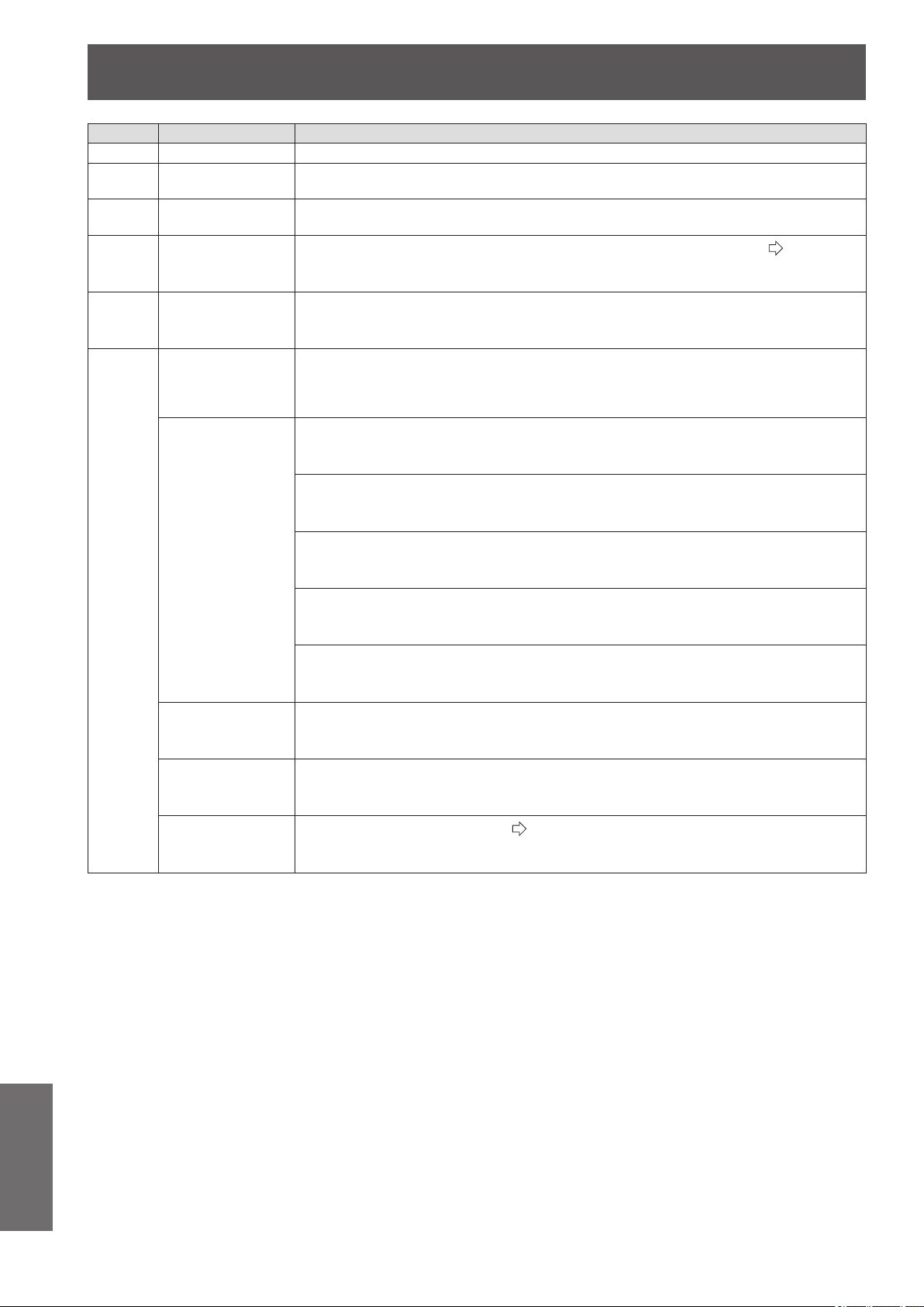
Technical information
104 -
ENGLISH
Appendix
Command
Control contents Remarks
KST KEYSTONE Displays the individual adjustment screen of [KEYSTONE].
DAM ADVANCED MENU
Displays the individual adjustment screen of the [ADVANCED] menu operated immediately
before this operation.
OAS AUTO SETUP
Operates AUTO SETUP.
COMPUTER IN (RGB) signals only (exc. movie based signals)
OOT SLEEP
Sets the duration of time after which the power is to be turned off automatically. (
page 80)
0 = OFF 1 = 60MIN. 2 = 90MIN. 3 = 120MIN. 4 = 150MIN.
5 = 180MIN. 6 = 210MIN. 7 = 240MIN.
O3D 3D SETTINGS Displays the [3D SETTINGS] menu screen.
VXX
LENS MEMORY
LOAD
Loads LENS MEMORY.
LMLI0 = +00000 = LENS MEMORY 1 LMLI0 = +00001 = LENS MEMORY 2
LMLI0 = +00002 = LENS MEMORY 3 LMLI0 = +00003 = LENS MEMORY 4
LMLI0 = +00004 = LENS MEMORY 5 LMLI0 = +00005 = LENS MEMORY 6
GAMMA
ADJUSTMENT
Sets Y ADJUST. (OUTPUT)
AGOS0 = p1p2d1d2d3d4
p1p2 = POINT (01 - 15) d1d2d3d4 = OUTPUT (0000 - 0255)
Sets R ADJUST. (OUTPUT)
AGOS1 = p1p2d1d2d3d4
p1p2 = POINT (01 - 15) d1d2d3d4 = OUTPUT (0000 - 0255)
Sets G ADJUST. (OUTPUT)
AGOS2 = p1p2d1d2d3d4
p1p2 = POINT (01 - 15) d1d2d3d4 = OUTPUT (0000 - 0255)
Sets B ADJUST. (OUTPUT)
AGOS3 = p1p2d1d2d3d4
p1p2 = POINT (01 - 15) d1d2d3d4 = OUTPUT (0000 - 0255)
Sets GAMMA ADJUSTMENT. (INPUT)
AGIS0 = p1p2d1d2d3
p1p2 = POINT (01 - 15) d1d2d3 = INPUT (001 - 099)
TRIGGER 1
(OUTPUT)
Switches TRIGGER 1 (OUTPUT) when RS-232C COMMAND LINK is set in the TRIGGER 1
SETTING menu.
TROI0 = +00000 = LOW TROI0 = +00001 = HIGH
TRIGGER 2
(OUTPUT)
Switches TRIGGER 2 (OUTPUT) when RS-232C COMMAND LINK is set in the TRIGGER 2
SETTING menu.
TROI1 = +00000 = LOW TROI1 = +00001 = HIGH
3D INPUT FORMAT
Switches the [3D INPUT FORMAT].(
page 64)
DIFI1=+00000 = AUTO DIFI1=+00001 = NATIVE
DIFI1=+00003 = SIDE BY SIDE DIFI1=+00004 = TOP AND BOTTOM
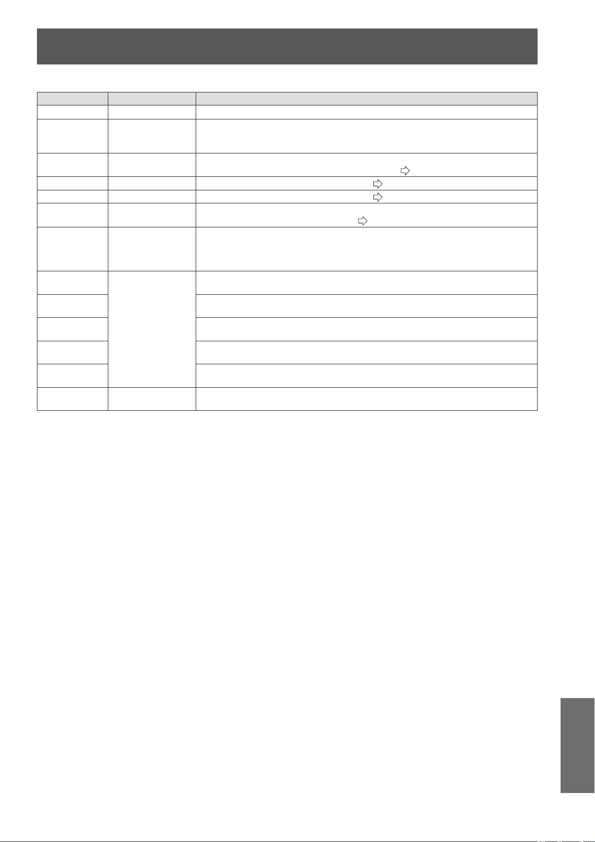
Technical information
ENGLISH
- 105
Appendix
<Inquiry commands>
Command
Control contents Parameter
QPW Power status 000 = OFF 001 = ON
QIN INPUT signal status
CP1 = COMPONENT IN SVD = S-VIDEO IN
VID = VIDEO IN HD1 = HDMI 1 IN HD2 = HDMI 2 IN HD3 = HDMI 3 IN
RG1 = COMPUTER IN
QPM
PICTURE MODE
status
NOR = NORMAL DYN = DYNAMIC 709 = REC709 DCN = D-CINEMA
CN1 = CINEMA1 CN2 = CINEMA2 GM1 = GAME (
page
40)
QSH BLANK status 0 = OFF 1 = ON (
page 83)
QFZ FREEZE status 0 = OFF 1 = ON (
page 83)
QOT
OFF TIMER
status
0 = OFF 1 = 60MIN. 2 = 90MIN. 3 = 120MIN. 4 = 150MIN.
5 = 180MIN. 6 = 210MIN. 7 = 240MIN. (
page 80)
QWM
WAVEFORM
status
Parameter
0 = OFF 1 = FULL SCAN(Y) 2 = FULL SCAN(R) 3 = FULL SCAN(G)
4 = FULL SCAN(B) 5 = SINGLE LINE SCAN(Y) 6 = SINGLE LINE SCAN(R)
7 = SINGLE LINE SCAN(G) 8 = SINGLE LINE SCAN(B)
QVX:AGOS0
GAMMA
ADJUSTMENT
status
AGOS0 = p1p2d1d2d3d4
p1p2 = POINT (01 - 15) d1d2d3d4 = OUTPUT (0000 - 0255)
QVX:AGOS1
AGOS1 = p1p2d1d2d3d4
p1p2 = POINT (01 - 15) d1d2d3d4 = OUTPUT (0000 - 0255)
QVX:AGOS2
AGOS2 = p1p2d1d2d3d4
p1p2 = POINT (01 - 15) d1d2d3d4 = OUTPUT (0000 - 0255)
QVX:AGOS3
AGOS3 = p1p2d1d2d3d4
p1p2 = POINT (01 - 15) d1d2d3d4 = OUTPUT (0000 - 0255)
QVX:AGIS0
AGIS0 = p1p2d1d2d3
p1p2 = POINT (01 - 15) d1d2d3 = INPUT (001 - 099)
QVX:DIFI1
3D INPUT FORMAT
status
DIFI1=+00000 = AUTO DIFI1=+00001 = NATIVE
DIFI1=+00003 = SIDE BY SIDE DIFI1=+00004 = TOP AND BOTTOM
Specications
106 -
ENGLISH
Appendix
Specications
The following table describes the specications of the projector.
Power supply AC 100-240 V 50 Hz/60 Hz
Power consumption
Less than 310 W
During standby (when fan is stopped): 0.08 W
Amps 3.8 A - 1.5 A
LCD panel
Panel size (diagonal) 18.7 mm (0.74")
Aspect ratio 16 : 9
Display method 3 transparent LCD panels (RGB)
Drive method Active matrix method
Pixels 2 073 600 (1 920 x 1 080) x 3 panels
Lens
Motorized zoom (2x)/Motorized focus
F 1.9 - 3.2, f 22.4 mm - 44.8 mm
Lamp UHM lamp (220 W)
Luminosity
*1
2 400 lm
Operating environment
Temperature
0 °C - 40 °C (32 °F - 104 °F)
When [HIGH ALTITUDE MODE]
(
page 80)
is set to [ON]: 0 °C -
35 °C (32 °F - 95 °F)
Humidity 20% - 80% (no condensation)
Scanning
frequency
*2
(for RGB signal)
Horizontal scanning
frequency
15 kHz - 74 kHz
Vertical scanning
frequency
24 Hz - 85 Hz
Dot clock frequency Less than 154 MHz
COMPONENT (YP
B
P
R
) signals
525i (480i), 625i (576i), 525p (480p), 625p (576p), 750 (720)/60p,
750 (720)/50p, 1 125 (1 080)/60i, 1 125 (1 080)/50i,
1 125 (1 080)/60p, 1 125 (1 080)/50p, 1 125 (1 080)/24p
Color system 7 (NTSC/NTSC 4.43/PAL/PAL-M/PAL-N/PAL60/SECAM)
Projection size
When displaying 3D images 1.02 m - 5.08 m (40" - 200")
When displaying 2D images 1.02 m - 7.62 m (40" - 300")
Projection distance
When displaying 3D images 1.2 m - 12.0 m (3'11" - 39'4") (16:9 size)
When displaying 2D images 1.2 m - 18.1 m (3'11" - 59'5") (16:9 size)
Screen aspect ratio 16 : 9
Installation
FRONT/DESK, FRONT/CEILING, REAR/DESK, REAR/CEILING
(Menu selection method)
*1. Measurement, measuring conditions and method of notation all comply with ISO21118 international
standards.
*2. For details of video signals that can be projected with this projector, see the “List of compatible signals”
(
page 100).
Specications
ENGLISH
- 107
Appendix
Terminals
S-VIDEO IN 1 set, Mini DIN 4p Y: 1.0 V [p-p], C: 0.286 V [p-p], 75 Ω
VIDEO IN 1 set, RCA pin jack 1.0 V [p-p], 75 Ω
COMPUTER IN
1 set, D-sub HD 15-pin (female)
(RGB signal)
R.G.B. 0.7 V [p-p], 75 Ω
G.SYNC 1.0 V [p-p], 75 Ω
HD/SYNC
*1
TTL high impedance, automatic
positive/negative polarity
compatible
VD
*1
TTL high impedance, automatic
positive/negative polarity
compatible
(Y, P
B
/C
B
, P
R
/C
R
signal)
Y: 1.0 V [p-p] (including sync), 75 Ω
P
B
/C
B
, P
R
/C
R
0.7 V [p-p], 75 Ω
COMPONENT IN
1 set, RCA pin jack x 3
Y: 1.0 V [p-p] (including sync), 75 Ω
P
B
/C
B
, P
R
/C
R
0.7 V [p-p], 75 Ω
HDMI IN
3 sets, 19-pin HDMI connector
(HDCP / Deep color / HDAVI Control Ver. 5 compliant)
SERIAL 1 set, D-sub 9-pin RS-232C compatible
TRIGGER / 3D
SHUTTER OUT
2 sets, monaural mini jack DC 12 V, max.100 mA
(Selectable for input and output by menu operation.)
Cabinet Moulded plastic (PC+ABS)
Dimensions
Width 470 mm (18 1/2")
Height 151 mm (5 15/16")
Depth 364 mm (14 11/32")
Weight Approx. 8.7 kg (19.18 lbs.)
*2
Certications
UL60950-1,2nd Ed. ,C-UL CSA C22.2 No 60950-1, 2nd Ed.
Part 15 of the FCC Rules
Remote control
Power supply DC 3 V (AA/R6/LR6 battery x 2)
Operating range Approx. 7 m (23') (when operated directly in front of signal receptor)
Weight 125 g (4.4 ozs.) (including batteries)
Dimensions
Width 48 mm (1 7/8")
Length 138 mm (5 7/16")
Height
28.3 mm (1 1/8") (not including
surface projection parts)
*1. HD/SYNC, and VD terminals do not accept tri-level sync signals.
*2. Average value. Weight varies for each product.
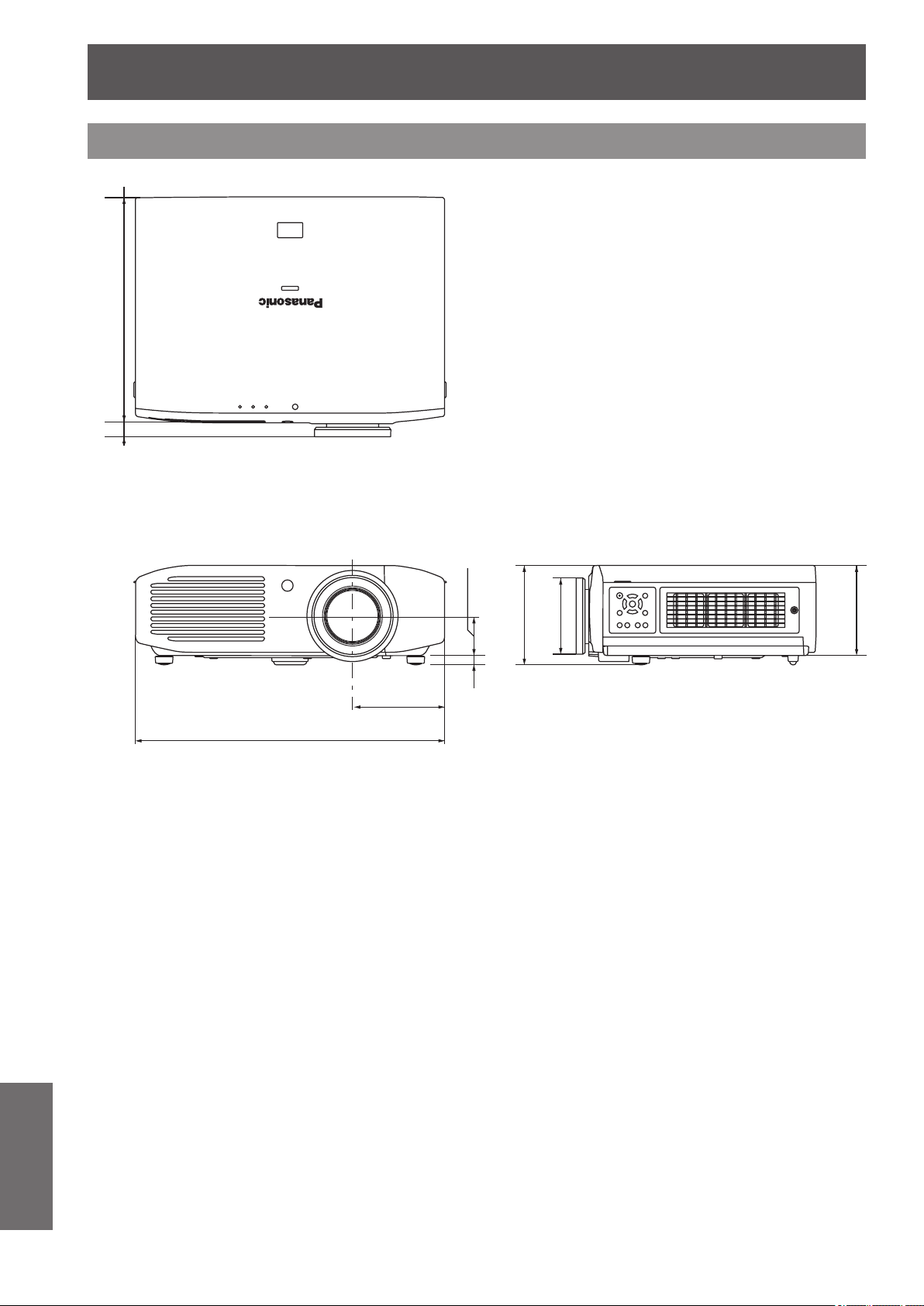
Specications
108 -
ENGLISH
Appendix
Dimensions
Unit: mm
470
(18 1/2")
140
(5 1/2")
60
(2 3/8")
14
(9/16")
345
(13 19/32")
19
(3/4")
151
(5 15/16")
116
(4 9/16")
137
(5 13/32")

Index
ENGLISH
- 109
Appendix
Index
Numbers
2D TO 3D ..................................................69
3D Eyewear ..............................................36
3D EYEWEAR BRIGHTNESS ................70
3D INPUT FORMAT ................................. 64
3D IR TRANSMITTER .............................70
3D MOTION REMASTER ....................... 72
3D PICTURE BALANCE .........................66
3D SAFETY PRECAUTIONS .................72
3D SETTINGS ....................................34, 39
3D VIEWING MONITOR .........................71
3D WAVEFORM MONITOR ....................67
A
About your projector .................................18
Accessories ..............................................17
Adjusting the picture .................................32
ADVANCED MENU .................................45
Air lter ...................................................... 89
Air lter unit ...............................................87
ASPECT ................................................... 61
AUTO SEARCH ....................................... 78
AUTO SETUP ..........................................63
AUTO SWITCHING .................................75
B
BACK COLOR .......................................... 77
BLANK ......................................................83
BRIGHTNESS ....................................40, 51
C
Cautions on use .......................................16
Cautions when installing ..........................14
CINEMA REALITY ...................................57
Cleaning ....................................................87
CLOCK PHASE .......................................60
COLOR .....................................................40
COLOR MANAGEMENT .........................52
COLOR TEMPERATURE........................ 41
Compatible signals .........................100, 106
Connections ..............................................26
CONTRAST ........................................40, 51
Control commands .................................103
D
DETAIL CLARITY .....................................56
Dimensions .............................................108
Displaying the waveform monitor ............33
Disposal .................................................... 16
DOT CLOCK ............................................60
DYNAMIC IRIS .........................................41
E
Electrostatic lter ......................................89
ENERGY SAVING MODE .......................82
F
Focus ........................................................ 32
FRAME CREATION .................................51
FRAME RESPONSE ............................... 78
FREEZE....................................................83
FUNCTION ...............................................34
FUNCTION BUTTON ..............................81
G
GAMMA ADJUSTMENT ..........................45
H
H-AREA POSITION .................................76
HDMI SIGNAL LEVEL .............................78
HIGH ALTITUDE MODE .......................... 80
H-POSITION ............................................60
I
INPUT GUIDE ..........................................77
K
KEYSTONE ..............................................63
L
Lamp indicator <LAMP> .......................... 86
LAMP POWER .........................................81
LAMP RUNTIME ......................................83
Lamp unit ..................................................89
LANGUAGE .............................................39
LEFT MASKING AREA ............................76
LEFT/RIGHT SWAP ................................66
LENS CONTROL ...............................39, 73
LENS MEMORY EDIT .............................74
LENS MEMORY LOAD ...........................73
LENS MEMORY SAVE ............................ 74
Lens shift ...................................................24
LOWER MASKING AREA .......................76
M
MEMORY DELETE .................................. 59
MEMORY LOAD ......................................59
MEMORY NAME CHANGE ....................59
MEMORY SAVE ....................................... 58
MENU .......................................................37
Menu list .................................................... 38
Menu navigation .......................................37
MPEG NR .................................................51
N
NR .............................................................51
O
ON-SCREEN DISPLAY ........................... 77
OPTION ....................................................39
Optional accessories ................................17
OSD DESIGN ........................................... 77
OSD POSITION .......................................77
OTHER FUNCTIONS .............................. 83
OVER SCAN ............................................63
P
Part replacement ......................................87
PICTURE ..................................................38
PICTURE BALANCE MEMORY .............67
PICTURE MEMORY ................................58
PICTURE MODE .....................................40
POSITION ................................................38
Positioning ................................................24
Power cord................................................28
Power indicator .........................................28
POWER OFF LINK ..................................82
POWER ON LINK .................................... 82
Precautions for use ..................................14
PROCESSING MESSAGE .....................76
Projecting an image .................................31
PROJECTION METHOD ........................78
Projector body ..........................................19
R
Read this rst! .............................................6
Remote control ...................................18, 32
Resetting to the default settings .............. 33
RGB/YC
B
C
R
..............................................58
RGB/YP
B
P
R
.............................................. 58
RIGHT MASKING AREA .........................76
S
SCREEN SIZE .........................................64
Selecting the picture mode ......................32
Serial terminal .........................................102
Setting up .................................................. 21
SHARPNESS ........................................... 41
SIGNAL MODE ........................................59
SLEEP ......................................................80
Specications .........................................106
SPLIT ADJUST .........................................44
STARTUP LOGO .....................................78
Supported 3D video signal list ...............101
Switching the projector on/off ................... 28
Switch input ..............................................34
T
Temperature indicator <TEMP> ..............85
TEST PATTERN .......................................83
TINT ..........................................................40
TRIGGER 1/2 SETTING ..........................
79
Troubleshooting ........................................94
TV-SYSTEM .............................................57
U
UNUSED DEVICE ENERGY SAVE .......82
UPPER MASKING AREA ........................76
Using VIERA Link .....................................96
V
V-AREA POSITION ..................................76
VIERA LINK ........................................81, 83
VIERA LINK SETTINGS ..........................81
Viewing in 3D ............................................35
V-POSITION .............................................60
W
WAVEFORM MONITOR ..........................41
WSS ..........................................................63
X
x.v.Color ....................................................56
Z
Zoom .........................................................32
ZOOM/FOCUS .........................................73

Panasonic System Communications Company of North America
One Panasonic Way 2F-13, Secaucus, NJ 07094
TEL: (877) 803 - 8492
Panasonic Canada Inc.
5770 Ambler Drive, Mississauga, Ontario L4W 2T3
TEL: (905) 624 - 5010
ヱㄏㄔㄐㄏㄊチヤㄐㄓㄑㄐㄓㄕㄊㄐㄏ
Web Site : http://panasonic.net/avc/projector/
© Panasonic Corporation 2012
M0912KM0 -KI
Information on Disposal in other Countries outside the European Union
These symbols are only valid in the European Union.
If you wish to discard this product, please contact your local authorities or dealer and ask for
the correct method of disposal.