Gas Continuous Flow Water Heater
Operation & Installation Manual
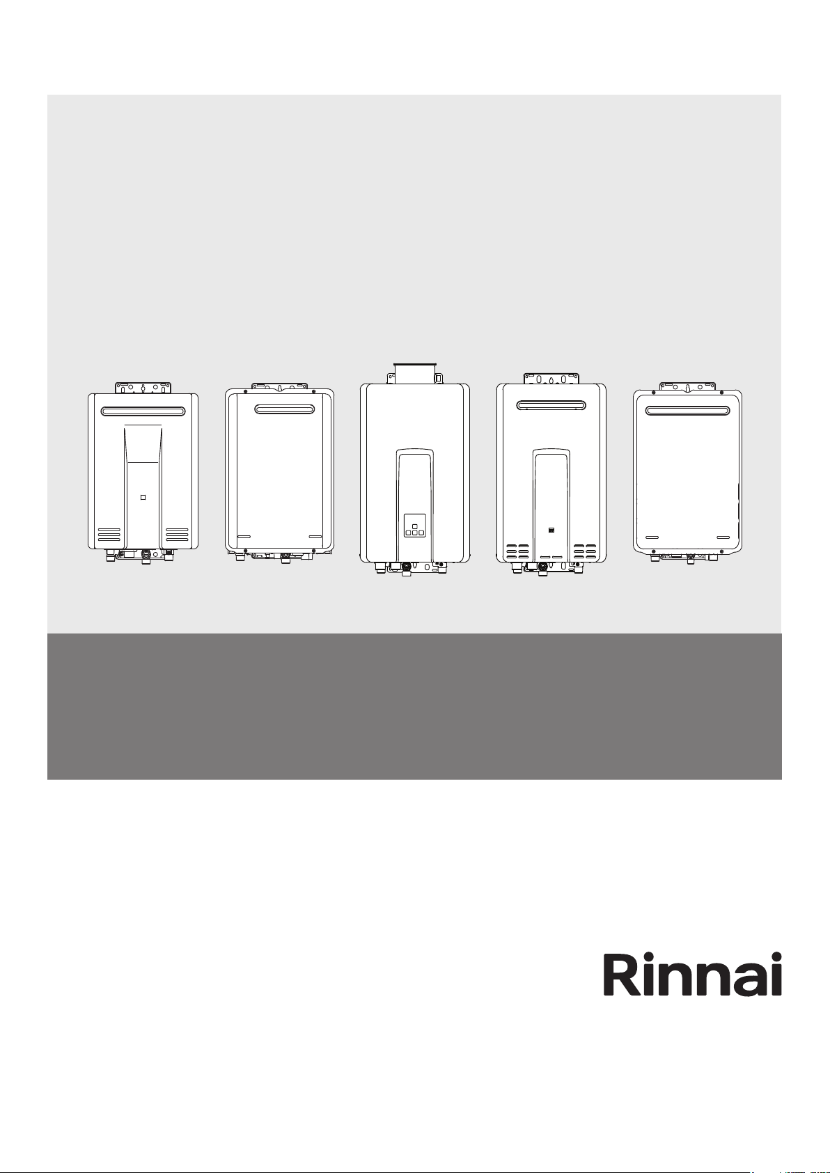
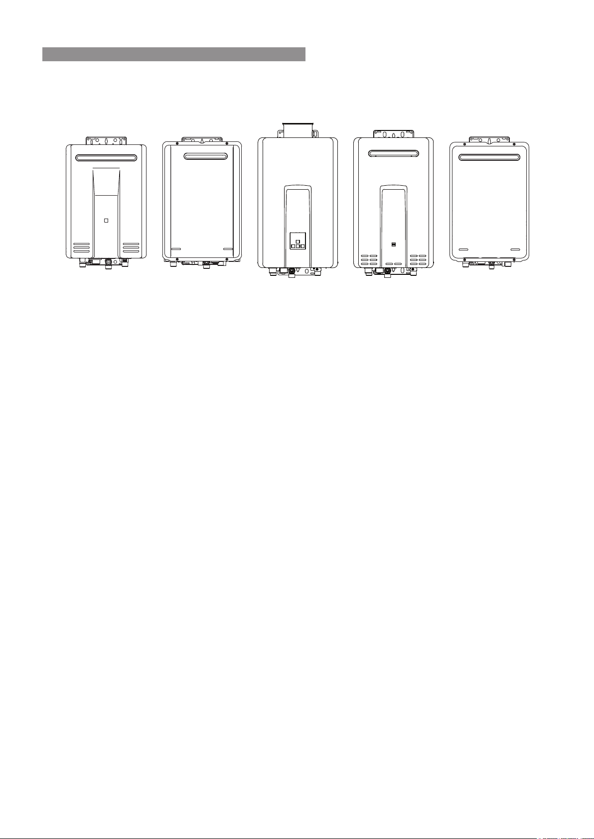
MODELS
Infinity 32 (REU-AM3237W)
HD32e (REU-AM3237WC)
Infinity 26 Touch (REU-AM2626WDL)
Infinity 26 (REU-AM2626WD)
Infinity 20 (REU-AM2024WD)
Infinity 16 (REU-AM1620WD)
Infinity 12 (REU-AM1220WD)
Infinity Enviro 26 (REU-E2626W)
Infinity Enviro 16 (REU-E1620W)
Infinity 28i (REU-VCM2837FF)
HD28i (REU-VCM2837FFC)
HD28e (REU-VCM2837WC)
B26 (REU-A2626WB)
B20 (REU-A2024WB)
B16 (REU-A1620WB)
Rinnai 2 HW_CF OIM
Congratulations on the purchase of your Rinnai Gas Continuous Flow Water Heater. We trust you will have many
years of comfort and enjoyment from your appliance.
IMPORTANT
BEFORE USING THIS APPLIANCE
Before proceeding with the operation or installation read this manual thoroughly and gain a full
understanding of the appliance, to ensure safe and correct use.
This appliance must be installed in accordance with:
• Manufacturer’s Installation Instructions
• Current AS/NZS 3000, AS/NZS 3500 & AS/NZS 5601
• Plumbing Code of Australia (PCA)
• Local Regulations and Municipal Building Codes
including local OH&S requirements
This appliance must be installed, maintained and removed
by an Authorised Person.
For continued safety of this appliance it must be installed
and maintained in accordance with the manufacturer’s
instructions.
All Rinnai gas products
sold in Australia are
A.G.A. certified.

Rinnai 3 HW_CF OIM
OPERATION TABLE OF CONTENTS
Warnings & Important Information 4
Before Using This Appliance .............................................................................................................................................. 4
Regulatory Information ....................................................................................................................................................... 4
Notice to Victorian Consumers .......................................................................................................................................... 4
Warning About Hot Water ................................................................................................................................................... 4
Operational Safety Information ......................................................................................................................................... 5
)HDWXUHV%HQH¿WV ............................................................................................................................................................. 7
Water Temperature Control 8
Maximum Delivery Temperatures ....................................................................................................................................... 8
Operation Without Water Controllers ................................................................................................................................ 8
Rinnai Water Controllers ..................................................................................................................................................... 8
Location ............................................................................................................................................................................. 8
Water Resistance .............................................................................................................................................................. 8
Temperature Control ......................................................................................................................................................... 9
:DWHU&RQWUROOHU&RQ¿JXUDWLRQV ........................................................................................................................................ 9
Universal Water Controller (MC-601Q) Operation ......................................................................................................... 10
7XUQLQJ2Q ...................................................................................................................................................................... 10
$GMXVWLQJ7HPSHUDWXUH .................................................................................................................................................... 10
7UDQVIHUULQJ3ULRULW\ ......................................................................................................................................................... 10
:DWHU&RQWUROOHU&RPELQDWLRQV&RQ¿JXUDWLRQV............................................................................................................ 10
Smartstart Pre-Heat System ..............................................................................................................................................11
3UHKHDW)XQFWLRQ ..............................................................................................................................................................11
3UHKHDW2SHUDWLRQ ............................................................................................................................................................11
Water Controller Functions ...............................................................................................................................................11
Trouble Shooting 12
Error Codes ........................................................................................................................................................................ 12
1RSRZHUGLVSOD\:LUHOHVV:DWHU&RQWUROOHUZKHQ¿WWHG .............................................................................................. 13
7URXEOHVKRRWLQJ:LWKRXW:DWHU&RQWUROOHUV .................................................................................................................... 13
Service ................................................................................................................................................................................ 13
Installation Table of Contents 14
Contacts 40
Rinnai 4 HW_CF OIM
WARNING
BEFORE USING THIS APPLIANCE
Before proceeding with the operation or installation read this manual thoroughly and gain a full
understanding of the appliance, to ensure safe and correct use.
Always comply with the following precautions to avoid dangerous situations and to ensure
optimum performance.
Failure to carefully read and follow all instructions in this manual can result in equipment
malfunction, property damage, personal injury and/or death.
DANGER: Indicates an imminently hazardous situation which, if not avoided, will result in
personal injury or death.
WARNINGS: Indicates a potentially hazardous situation which, if not avoided, could result in
personal injury or death.
CAUTIONS: Indicates a potentially hazardous situation which, if not avoided, could result in
minor or moderate injury or damage to the appliance. It may also be used to alert against unsafe
practices.
WARNING
REGULATORY INFORMATION
<RXU5LQQDLJDVFRQWLQXRXVÀRZZDWHUKHDWHU KDVEHHQFHUWL¿HGE\WKH$XVWUDOLDQ*DV$VVRFLDWLRQ
7KH$*$&HUWL¿FDWLRQ1XPEHULVVKRZQRQWKHGDWDSODWH
This Appliance must be installed correctly by an appropriately licensed tradesperson. The
installation of gas, water, and electricity must conform to local regulations.
The installation of gas, water, and electricity must conform to local regulations, including local
OH&S requirements. The installation must also comply with the instructions supplied by Rinnai.
Please keep this instruction booklet in a safe place for future reference.
$OOGLPHQVLRQVUHIHUUHGWRLQWKHVHLQVWUXFWLRQVDUHLQPLOOLPHWUHVXQOHVVRWKHUZLVHVSHFL¿HG
Notice to Victorian Consumers
This appliance must be installed by a person licensed with the Victorian Building Authority. Only
a licensed person will have insurance protecting their workmanship. So make sure you use a
OLFHQVHGSHUVRQWRLQVWDOOWKLVDSSOLDQFHDQGDVNIRU\RXU&RPSOLDQFH&HUWL¿FDWH
For further information contact the Victorian Building Authority on 1300 815 127.
WARNING
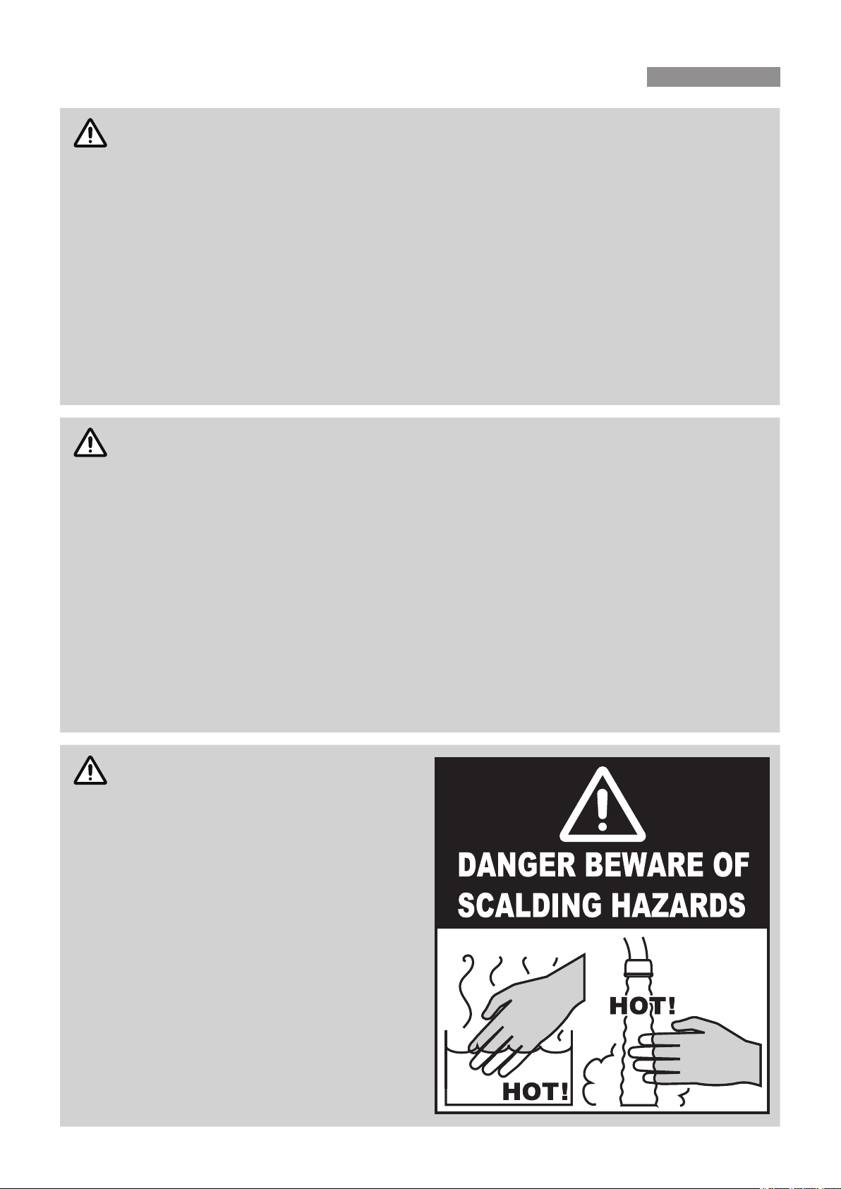
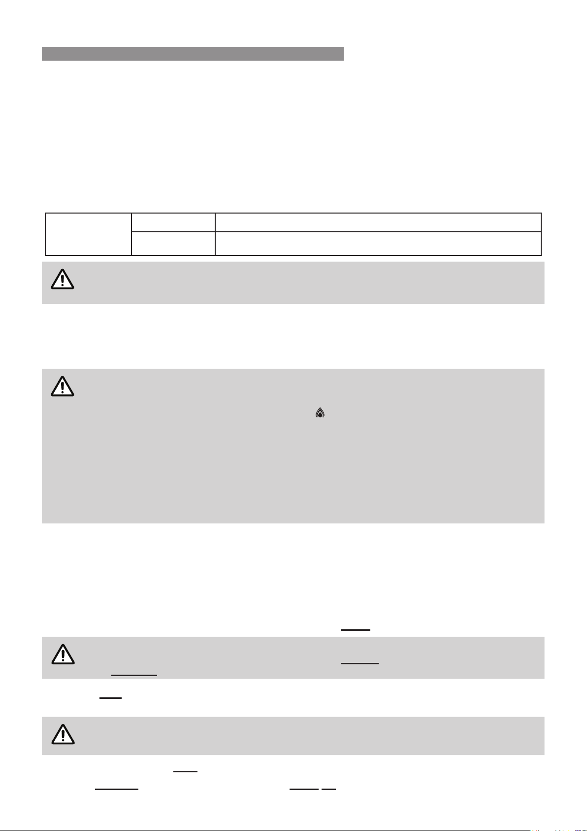
WARNING ABOUT HOT WATER
Hot water can cause scalding. Those most
at risk are children and disabled, elderly and
LQ¿UP SHUVRQV & ZDWHU FDQ VHYHUHO\
burn a child in half a second).
Rinnai have water heater models which
OLPLWWKHGHOLYHU\WHPSHUDWXUHWR&ZKLFK
VLJQL¿FDQWO\ UHGXFHV WKH VFDOG KD]DUG
Temperature limiting devices may also be
DEOHWREH¿WWHG&RQWDFW5LQQDLIRUIXUWKHU
information.
ALWAYS test the water temperature before
XVHVXFKDVZKHQ¿OOLQJDEDWKRUEDVLQRU
entering a shower, to ensure it is suitable
for the application and will not cause scald
injury.
ALWAYS supervise children whenever
they are in the bathroom or near other
sources of hot water. Ensure any hot water
WDSVDUHFORVHG¿UPO\DIWHUXVH
WARNINGS & IMPORTANT INFORMATION
Rinnai 5 HW_CF OIM
Operational Safety Information
IMPORTANT
This appliance is not intended for use by persons (including children) with reduced physical,
sensory or mental capabilities, or lack of experience and knowledge, unless they have been given
supervision or instruction concerning use of the appliance by a person responsible for their
safety. Children should be supervised to ensure that they do not play with the appliance.
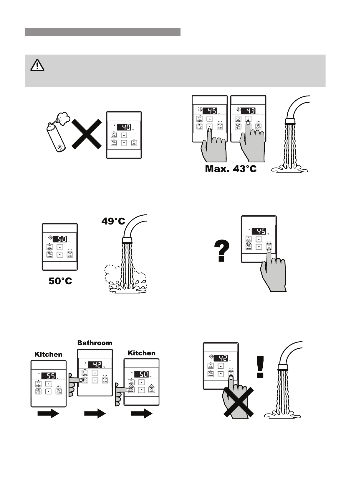
To clean your water controller(s) use a soft damp cloth
with a mild detergent.
'2127 use solvents!
Whilst hot water outlets are open the set temperature
may be lowered. However they cannot then be raised
above 43°C. In addition transfer of 'priority' between
controllers is not possible. These are safety features.
Depending on the weather conditions and the length
of the pipe between the hot water unit and the
outlet in use, there may be a variation between the
temperatures displayed at the water controller(s) and
the temperature of the water at the outlet.
7KHUH LV QR QHHG WR WXUQ WKH ZDWHU FRQWUROOHUV Rႇ
after use. However, if you prefer to turn the water
FRQWUROOHUV Rႇ \RXU VHOHFWHG WHPSHUDWXUHV WR D
maximum of 50°C will be stored in the system memory
at all times whilst mains power remains connected.
As a safety precaution, if a Kitchen Water Controller's
temperature is set above 50°C, transferring and then
returning 'priority' to the Kitchen Water Controller will
result in a set temperature of 50°C being selected.
When 'priority' is returned to Water Controllers other
than the Kitchen the temperature will be 42°C.
'2 127 SXVK WKH 2Q2ႇ EXWWRQ RQ DQ\ :DWHU
Controller when the water heater ‘In Use’ indicator is
LOOXPLQDWHGDVWKLVZLOOWXUQRႇWKHZDWHUKHDWHUFDXVLQJ
the water to go cold. Someone maybe in the middle of
KDYLQJDVKRZHURU¿OOLQJDEDWK
S
O
L
V
E
N
T
WARNINGS & IMPORTANT INFORMATION
Rinnai 6 HW_CF OIM
IMPORTANT
7KHUDQJHRI5LQQDLJDVFRQWLQXRXVÀRZZDWHUKHDWHUVUHIHUUHGWRLQWKLVPDQXDODUHLQFRPSDWLEOH
ZLWKVRODUZDWHUKHDWLQJV\VWHPV$GHGLFDWHGUDQJHRIVRODUFRPSDWLEOHFRQWLQXRXVÀRZZDWHU
heaters is available from Rinnai.
If the supply cord is damaged, it must be replaced by the manufacturer, its service agent or
VLPLODUO\TXDOL¿HGSHUVRQVLQRUGHUWRDYRLGDKD]DUG
Always check water temperature carefully before use.
Refer to the :$51,1*$%287+27:$7(5on
page 4 for important safety information.
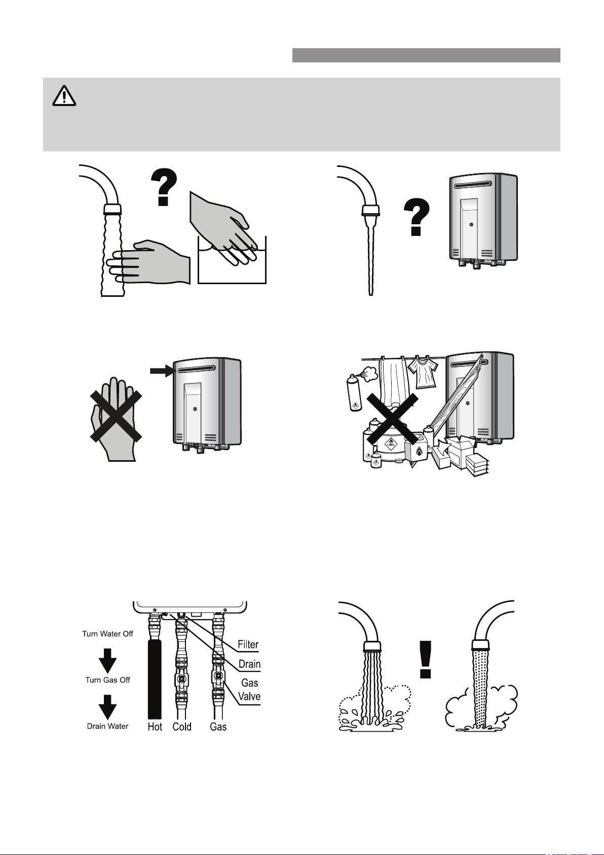
$WORZZDWHUÀRZVWKHKRWZDWHUXQLWPD\H[WLQJXLVK
without warning. Opening the tap further will restart
the heating appliance.
'2127WRXFKWKHXQLWFRYHURUWKHÀXHRXWOHW
'2127LQVHUWREMHFWVLQWRWKHÀXHRXWOHW
'2127VSUD\ZDWHUGLUHFWO\LQWRWKHÀXHRXWOHW
.HHSWUHHVVKUXEVHWFZHOOFOHDURIWKHÀXHRXWOHW
2QFROGHUGD\VVWHDPPD\GLVFKDUJHGIURPWKHÀXH
RXWOHW 7KLV FRQGLWLRQ LV QRUPDO IRU KLJK HႈFLHQF\
appliances and does not indicate a fault.
'2127Spray aerosols in the vicinity of this appliance
while it is in operation.
'2127XVHRUVWRUHÀDPPDEOHPDWHULDOVLQRUQHDU
this appliance.
'2127 place articles on or against this appliance.
'2127modify this appliance.
'2127store pool chemicals near this appliance.
,IIUHH]LQJFRQGLWLRQVDUHH[SHFWHGWXUQRႇZDWHUDQG
gas, and drain all water from the appliance. If power
and the automatic frost protection are connected,
freezing will be prevented. (Anti-frost protection is
¿WWHGDVVWDQGDUGHTXLSPHQWRQDOOKRWZDWHUXQLWV
The delivered water temperature is controlled
DXWRPDWLFDOO\ 7KH ÀRZ PD\ YDU\ GHSHQGLQJ RQ WKH
delivery temperature selected and the ambient water
temperature.
OFF!
HOT!
43°C 55°C
WARNINGS & IMPORTANT INFORMATION
Rinnai 7 HW_CF OIM
FEATURES & BENEFITS
&RQJUDWXODWLRQV RQ SXUFKDVLQJ WKH ODWHVW WHFKQRORJ\ WHPSHUDWXUH FRQWUROOHG 5LQQDL JDV FRQWLQXRXV ÀRZ ZDWHU
heater.
•
7KH5LQQDLJDVFRQWLQXRXVÀRZZDWHUKHDWHUSURGXFWV1(9(5581287of hot water. Whilst electricity,
water and gas supplies are connected, hot water is available whenever hot water taps are open.
•
Built into the main micro-processor is the facility to LIMIT THE MAXIMUM TEMPERATURE of the hot
water supplied. The water temperature may be limited to various values. This is particularly useful when the
KRWZDWHUXQLWLVLQVWDOOHGZKHUH\RXQJFKLOGUHQRUWKHLQ¿UPPD\EHXVLQJWKHKRWZDWHU
•
7KH 5LQQDL JDV FRQWLQXRXV ÀRZ ZDWHU KHDWHU SURGXFWV DUH )DQ$VVLVWHG SRZHU ÀXHG DSSOLDQFHV 7KLV
makes them COMPACTVDYLQJERWKÀRRUDQGZDOOVSDFH
•
The temperature of hot water is &2167$17/<021,725(' by a %8,/7,16(1625. If the temperature
of the hot water rises to more than 3°C above the selected temperature the burner is turned OFF and only
turned ON again when the temperature falls below the selected temperature.
•
The burner lights automatically when the hot water tap is opened, and goes out when the tap is closed.
,*1,7,21,6(/(&7521,&VRWKHUHLVQRSLORWOLJKW:KHQWKHKRWZDWHUWDSLVRႇQRJDVLVXVHG
•
'Deluxe' or 'Universal' Water Controllers are available as an optional extra. Depending on the models chosen,
WKHVHRႇHUWKHIROORZLQJIHDWXUHV
-
%DWK¿OOIXQFWLRQ'HOX[H%DWKURRP&RQWURO2QO\
-
Voice Prompting (Deluxe Control Only).
-
Clock (Deluxe Control Only).
-
8SWRIRXUZDWHUFRQWUROOHUVFDQEH¿WWHG6HHSDJHIRUGHWDLOV
For further information regarding Wireless and Deluxe water controllers please contact Rinnai or visit
www.rinnai.com.au.
•
7KH6PDUWVWDUWV\VWHPZKHQ¿WWHGFDQSUHKHDWWKHZDWHULQWKHSLSHZRUNEHWZHHQWKHZDWHUKHDWHUDQG
the hot water outlets. This results in water savings and reduces waiting time for heated water at the outlets.
•
Operating 12,6(/(9(/,69(5</2:.
•
(55250(66$*(6$5( ',63/$<(' on the Water Controllers and Status Monitor*, assisting with
VHUYLFH$OOPRGHOVLQWKHUDQJHFRYHUHGE\WKLVPDQXDOKDYHD³6WDWXV0RQLWRU´H[FHSW,Q¿QLW\(QYLUR
,Q¿QLW\(QYLUR%%%
•
The ,Q¿QLW\ 7RXFK (REU-AM2626WDL) water heater model is supplied with one "MC-503" wireless
water controller kit that includes a transceiver and a wireless water controller, that is pre-programmed as a
master controller. Additional "MC-503" wireless water controllers are available as an optional extra. Please
refer the separate wireless operation manual for instructions on how to use the supplied wireless water
controller.
WARNINGS & IMPORTANT INFORMATION
Rinnai 8 HW_CF OIM
MAXIMUM DELIVERY TEMPERATURES
5LQQDLJDVFRQWLQXRXVÀRZZDWHUKHDWHUVDUHIDFWRU\SUHVHWWRYDULRXVPD[LPXPGHOLYHU\WHPSHUDWXUHVGHSHQGLQJ
RQ PRGHO DQG WKHLU LQWHQGHG DSSOLFDWLRQ )RU WKH PDMRULW\ RI DSSOLFDWLRQV WKH IDFWRU\ SUHVHW WHPSHUDWXUH LV
DSSURSULDWH,QWKHXQOLNHO\HYHQWWKLVLVQRWWKHFDVHWKLVVHWWLQJFDQEHLQFUHDVHGRUGHFUHDVHGE\DQDXWKRULVHG
SHUVRQVXFKDVDOLFHQVHGSOXPEHU
NOTE
This does not apply to “50 degree compliant” models. To meet the regulatory requirements the
maximum delivery temperature is factory set and sealed.
)RUPRGHOVSHFL¿FLQIRUPDWLRQLQUHJDUGVWRWKHIDFWRU\SUHVHWWHPSHUDWXUHRI\RXUDSSOLDQFH
refer to "Table 2. Maximum Delivery Temperatures" on page 33. The appliance model number
can be found on the dataplate, which is located on the left hand side of appliance.
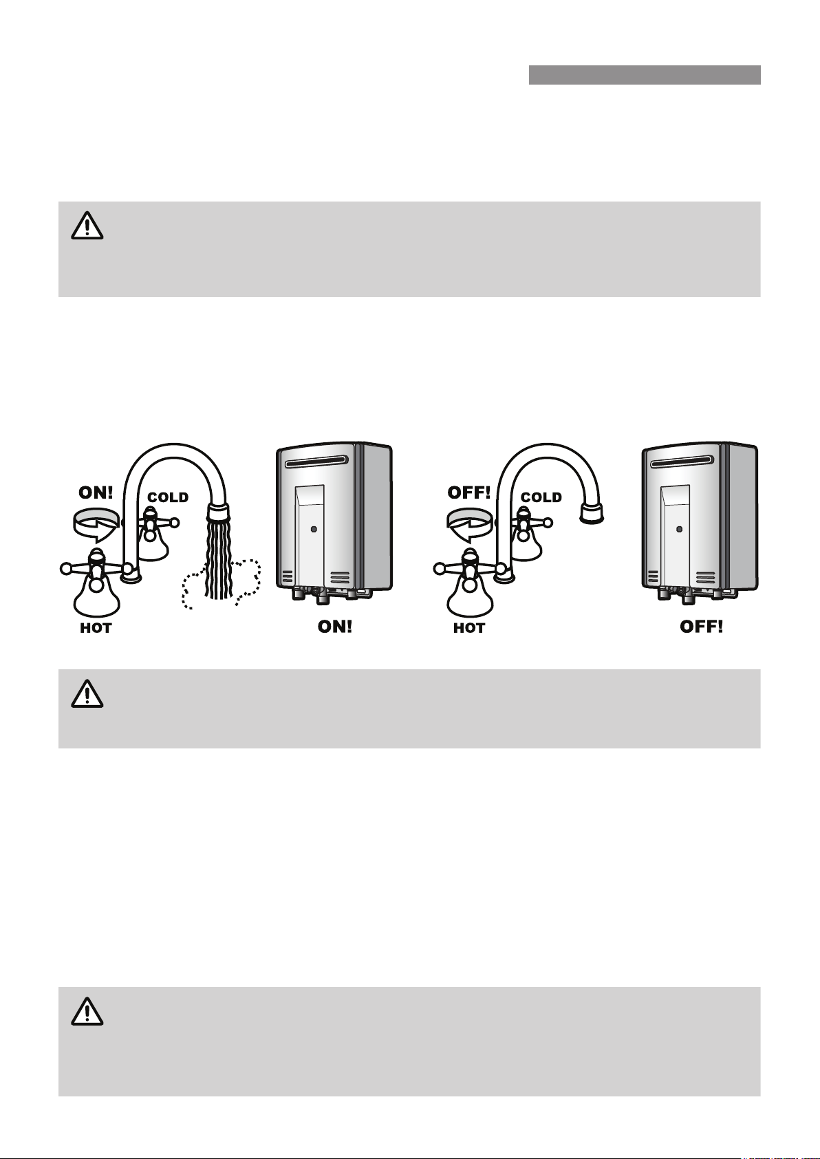
OPERATION WITHOUT WATER CONTROLLERS
5LQQDLJDVFRQWLQXRXVÀRZZDWHUKHDWHUSURGXFWVGRQRWXVHDSLORWOLJKW:KHQLQVWDOOHGDQGRSHUDWHGZLWKRXW
ZDWHUFRQWUROOHUVWKHRSHQLQJRIDQ\KRWZDWHUWDSZLOODXWRPDWLFDOO\VWDUWWKHDSSOLDQFH2QFHZDWHULVÀRZLQJ
WKURXJKWKHDSSOLDQFHWKHEXUQHUZLOOEHLJQLWHGE\HOHFWURQLFLJQLWLRQDQGZDWHUZLOOEHGHOLYHUHGDWWKHPD[LPXP
WHPSHUDWXUHWKDWWKHXQLWLVFDSDEOHRIGHOLYHULQJ$VZLWKFRQYHQWLRQDOZDWHUKHDWHUVFROGZDWHUZLOOQHHGWRDGGHG
WRUHGXFHWKHWHPSHUDWXUHWRWKHGHVLUHGOHYHO:KHQWKHKRWZDWHUWDSLVFORVHGDQGZDWHUFHDVHVWRÀRZWKURXJK
WKHDSSOLDQFHWKHEXUQHUÀDPHZLOOEHH[WLQJXLVKHG
RINNAI WATER CONTROLLERS
NOTE
Other manufacturers water controllers are NOT compatible with Rinnai water heaters. Rinnai
water controllers brought in from other countries are also NOT compatible with Rinnai appliances
sold in Australia.
Water controllers MUST NOT be used with any Solar Boost water heater.
:DWHU FRQWUROOHUV DUH DYDLODEOH DV DQ RSWLRQDO H[WUD :LUHOHVV 8QLYHUVDO DQG 'HOX[H ZDWHU FRQWUROOHUV FDQ EH
XVHGWRJHWKHUDQGZLOOIXQFWLRQDVGHVFULEHGLQWKH2SHUDWLRQ6HFWLRQVRIWKLVPDQXDO5HIHUWR:DWHU&RQWUROOHU
&RQ¿JXUDWLRQV RQ SDJH WR FRQ¿UP WKH PD[LPXP QXPEHU DQG FRPELQDWLRQ RI ZDWHU FRQWUROOHUV WKDW FDQ EH
¿WWHGWR\RXUZDWHUKHDWHUPRGHO
Location
:DWHUFRQWUROOHUVPXVWEHLQVWDOOHGLQVKDGHGDQGFOHDQORFDWLRQV7KH\VKRXOGEH¿WWHGRXWRIUHDFKRIFKLOGUHQ
VXJJHVWHGKHLJKWIURPÀRRUWREHDWOHDVWPP
Water Resistance
7KH0&4XQLYHUVDOZDWHUFRQWUROOHULVDZDWHUUHVLVWDQWGHYLFHKRZHYHUH[FHVVLYHH[SRVXUHWRZDWHUVXFKDV
LPPHUVLRQPD\UHVXOWLQGDPDJHWRWKHZDWHUFRQWUROOHU'XUDELOLW\RIZDWHUFRQWUROOHUVLVLPSURYHGZKHQSRVLWLRQHG
RXWVLGHRIWKHVKRZHUUHFHVV
NOTE
Controllers MUST BE installed at least 400 mm above the highest part of a sink, basin or bath.
DO NOT immerse the water controller into water.
AVOID direct exposure to water or steam as these conditions may cause a malfunction.
ALWAYS AVOID exposure to water when the battery compartment is open.
When cleaning your water controller use ONLY a damp cloth and a mild detergent.
WATER TEMPERATURE CONTROL
5LQQDL +:B&)2,0
Temperature Control
:DWHUFRQWUROOHUVDOORZSUHFLVHWHPSHUDWXUHFRQWUROE\WKHXVHU:KHQXVHGFRUUHFWO\WKHKRWZDWHUXQLWZLOOGHOLYHU
WKHVHOHFWHGWHPSHUDWXUHHYHQZKHQWKHZDWHUÀRZLVYDULHGRUPRUHWKDQRQHWDSLVLQXVH
2QO\RQH0&PRGHOZDWHUFRQWUROOHUFDQEHGHVLJQDWHGDVDµ0DVWHU¶ZDWHUFRQWUROOHUDQGWKLVLVQRUPDOO\XVHG
LQWKH NLWFKHQ$OO WKHUHPDLQLQJ ZDWHU FRQWUROOHUV DUH GHVLJQDWHGDV µ6XE¶ ZDWHU FRQWUROOHUV DQGDUH IRUXVH LQ
EDWKURRPVWRLOHWVDQGODXQGULHV7KHPD[LPXPWHPSHUDWXUHOLPLWIRUDOOµ6XE¶ZDWHUFRQWUROOHUVLVUHVWULFWHGWR&
WRPLQLPLVHWKHULVNRIEXUQVLQWKHVHDUHDV
$Q\ZDWHUFRQWUROOHUWKDWFXUUHQWO\KDVSULRULW\LVFDSDEOHRIVHWWLQJWKHZDWHUWHPSHUDWXUHWREHGHOLYHUHGKRZHYHU
WKHZDWHUKHDWHUFDQ RQO\ DVVLJQSULRULW\WRRQHFRQWUROOHU DW DWLPHDQGGHOLYHU WKH RQHVHWWHPSHUDWXUH7KH
DYDLODEOHWHPSHUDWXUHV&DUHDVIROORZV
:DWHU&RQWUROOHU
7HPSHUDWXUHV
&
0DVWHU0&
6XE0&RU%&
NOTE
Whilst hot water outlets are open ONLY the control used to set to delivery may be used to further
adjust it. Transfer of 'priority' between controllers is NOT possible until all hot water taps have
been closed. These are safety features.
)RUK\JLHQHLQVDQLWDU\DUHDVVXFKDVEDWKURRPVWKHVXJJHVWHGWHPSHUDWXUHVKRXOGEH&a&
7KH DERYH LV D VXJJHVWLRQ RQO\ DV \RX PD\ ¿QG KLJKHU RU ORZHU WHPSHUDWXUHV PRUH FRPIRUWDEOH KRZHYHU
PDLQWDLQLQJORZHUWHPSHUDWXUHVDOVRKHOSVWRVDYHHQHUJ\7RREWDLQZDWHUWHPSHUDWXUHVORZHUWKDQ&VLPSO\
RSHQWKHFROGZDWHUWDSDQGDGGFROGZDWHUXQWLOWKHGHVLUHGORZHUWHPSHUDWXUHLVUHDFKHG
NOTE
The temperature of outgoing hot water is constantly monitored by a built-in sensor. If the
WHPSHUDWXUHRI WKH RXWJRLQJKRW ZDWHU ULVHVWR PRUH WKDQ& DERYH WKHVHOHFWHG WHPSHUDWXUH
VKRZQRQWKHGLJLWDOPRQLWRURUWKHSUHVHWOLPLWZKHQZDWHUFRQWUROOHUVDUHQRW¿WWHGWKHEXUQHU
will automatically go out. The ‘in use’ indicator
will also go out. The burner will ignite again
once the outgoing hot water temperature falls to that shown on the digital monitor (or the pre-set
limit of the appliance)
* 7HPSHUDWXUHPD\QRWEHDYDLODEOHRQDOOLQVWDOODWLRQV6RPH5LQQDLJDVFRQWLQXRXVÀRZZDWHU
heaters can be programmed to deliver higher temperatures from the master water controller,
or may be programmed to restrict the maximum available delivery temperature. Contact
Rinnai for more details.
** 7HPSHUDWXUH OLPLWLQJ GHYLFHV ZKHUH ¿WWHG PD\ IXUWKHU FRQWURO ZKDW PD[LPXP GHOLYHU\
temperature is available to outlets.
8QLYHUVDO DQG :LUHOHVV DQG ZDWHU FRQWUROOHUV DOORZ WHPSHUDWXUH VHOHFWLRQ RQO\ 'HOX[H ZDWHU FRQWUROOHUV DOORZ
WHPSHUDWXUHVHOHFWLRQKDYHDFORFNIXQFWLRQDQGWKH'HOX[H%DWKURRPZDWHUFRQWUROOHUKDVDVKRZHUVDYHUEDWK
¿OOIXQFWLRQDOVRDYDLODEOH7R¿QGRXWPRUHDERXWWKHIXOOUDQJHRI5LQQDLZDWHUFRQWUROOHUPRGHOVLQFOXGLQJ:LUHOHVV
DQG'HOX[HZDWHUFRQWUROOHUVFRQWDFW5LQQDLRUYLVLWwww.rinnai.com.au
:DWHU&RQWUROOHU&RQÀJXUDWLRQV
9DULRXVFRPELQDWLRQVRI8QLYHUVDO'HOX[HDQG:LUHOHVVZDWHUFRQWUROOHUVFDQEH¿WWHGZLWKWKHIROORZLQJOLPLWDWLRQV
•
)RUDOOPRGHOVH[FHSWREU-VCM2837FF/FFCDPD[LPXPRIFOURZDWHUFRQWUROOHUVFDQEH¿WWHG
IMPORTANT
As REU-VCM2837FF/FFCPRGHOVDUH¿WWHGZLWKDEXLOWLQFRQWUROOHUWKHPD[LPXPQXPEHURI
DGGLWLRQDOFRQWUROOHUVWKDWFDQEH¿WWHGLVUHGXFHGWRTHREE, with the built-in controller acting
as a FOURTH controller.
•
2QO\21(PDVWHUFRQWUROOHUFDQEHLQVWDOOHG7KLVFDQEHDGHOX[HNLWFKHQ0&9RUDQ\RWKHU0&
PRGHOZDWHUFRQWUROOHUZKHQSURJUDPPHGWREHD0DVWHUFRQWUROOHU
IMPORTANT
:KHQDGHOX[HNLWFKHQ0&9ZDWHUFRQWUROOHULV¿WWHGLWZLOODOZD\VIXQFWLRQDVD0DVWHU
controller, this is the default setting and can NOT be changed.
•
$XSWRDPD[LPXPRITWO%&9ZDWHUFRQWUROOHUVFDQEHLQVWDOOHG
•
7KHFOURTHZDWHUFRQWUROOHULQDQ\LQVWDOODWLRQMUST BED0&4RUD0&5&6
WATER TEMPERATURE CONTROL
Rinnai 10 HW_CF OIM
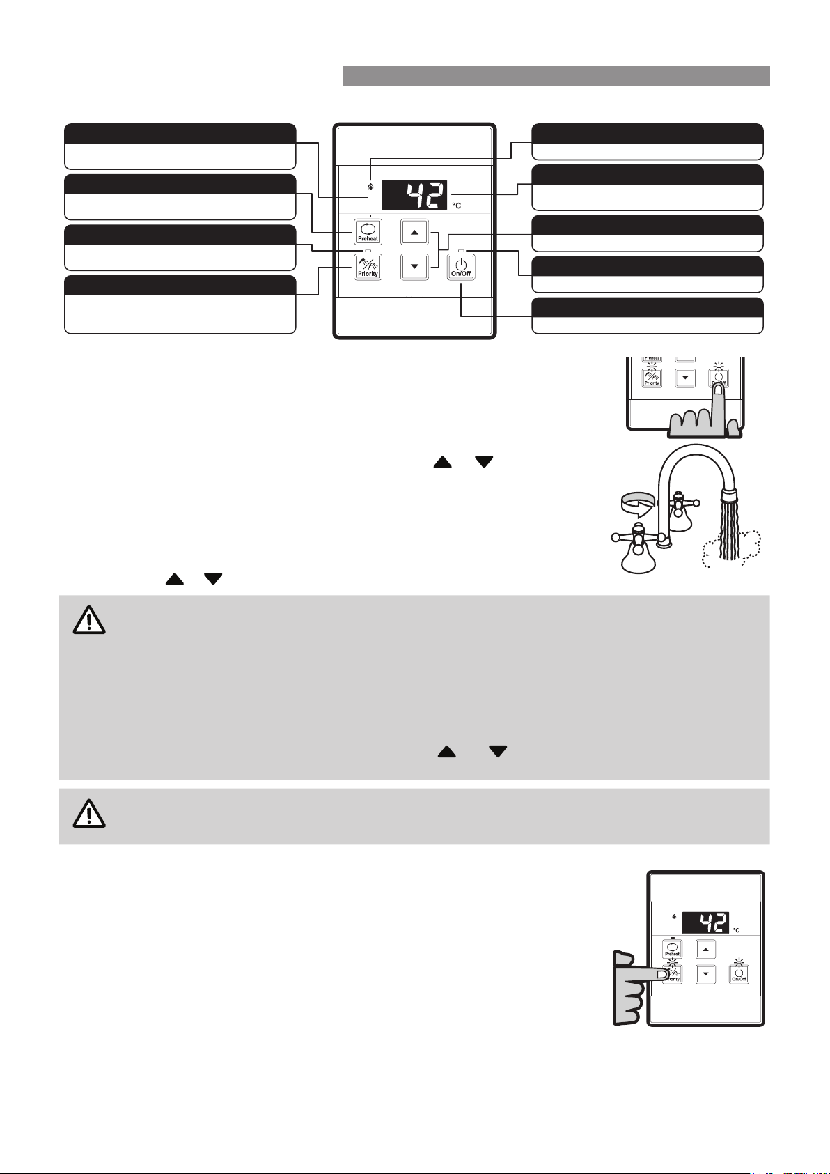
UNIVERSAL WATER CONTROLLER (MC-601Q) OPERATION
Turning On
,IWKHZDWHUFRQWUROOHULVVZLWFKHGRႇ1RGLJLWVGLVSOD\HGLQWKHGLJLWDOPRQLWRUZLQGRZ
SUHVVWKH2Q2ႇEXWWRQRQFH7KH21LQGLFDWRUZLOOLOOXPLQDWHLQGLFDWLQJWKDWWKHKRW
ZDWHUXQLWZLOOEHUHDG\WRVXSSO\KRWZDWHURQFHDKRWZDWHUWDSLVRSHQHG
Adjusting Temperature
6HOHFWWKHGHVLUHG WHPSHUDWXUHXVLQJWKH +RW ZDWHUWHPS
or EXWWRQVXQWLOWKH
UHTXLUHGWHPSHUDWXUHLVGLVSOD\HGRQWKHGLJLWDOPRQLWRU
7RRSHUDWHWKHKRWZDWHUXQLWRSHQDQ\KRWZDWHUWDS7KLVZLOODXWRPDWLFDOO\OLJKWWKH
EXUQHU SURYLGLQJ KRW ZDWHU7KH ZDWHU KHDWHU µ,Q 8VH¶LQGLFDWRU ZLOO LOOXPLQDWH RQ WKH
ZDWHUFRQWUROOHUV
2QFHWKHKRWZDWHULVUXQQLQJLIWKHVHWWHPSHUDWXUHLVHLWKHUWRRKRWRUFROGSUHVVWKH
+RWZDWHUWHPS or EXWWRQVXQWLOWKHGHVLUHGWHPSHUDWXUHLVUHDFKHG
NOTE
:KLOVWKRWZDWHURXWOHWVDUHRSHQWKHVHWWHPSHUDWXUHPD\EHORZHUHGWRDPLQLPXPRI&)RU
VDIHW\LWFDQQRWWKHQEHUDLVHGDERYH&XQWLODOOKRWZDWHUWDSVDUHFORVHG
,IWKHZDWHUKHDWHULVWXUQHGµ2ႇ¶ZKLOVWKRWZDWHUWDSVDUHRSHQLWFDQQRWEHWXUQHGEDFNµ2Q¶XQWLO
all hot water taps have been closed.
Temperatures higher than 50ºC MUST NOT be able to be selected on controllers installed in
bathrooms, ensuites or toilets. This is to help reduce the risk of burns from hot water. If this is not
the case, the controllers have been incorrectly installed. CONTACT YOUR INSTALLER.
The 'beep' sound can be muted by pressing the and buttons simultaneously for more than
3 seconds. To cancel sound muting, simply repeat the process.
CAUTION
Always check outlet water temperature before use. The parent / carer MUST check the temperature
before placing dependants in contact with hot water, see "Warning About Hot Water" on page 4.
Transferring Priority
7RFRQWUROWKHZDWHUGHOLYHU\WHPSHUDWXUHVZKHQXVLQJWZRRUPRUHZDWHUFRQWUROOHUVLWLV
QHFHVVDU\WRKDYHSULRULW\WUDQVIHUUHGWRWKHZDWHUFRQWUROOHU\RXZLVKWRXVH7UDQVIHUULQJ
RISULRULW\ZLOO127EHSRVVLEOHLIWKHµ,Q8VH¶LQGLFDWRULVFXUUHQWO\LOOXPLQDWHGDVWKLV
LQGLFDWHVKRWZDWHULVÀRZLQJDQGWKDWDQRWKHUZDWHUFRQWUROOHUDOUHDG\KDVSULRULW\
$QLOOXPLQDWHG3ULRULW\LQGLFDWRUFRQ¿UPVWKDWWKHGHVLUHGZDWHUFRQWUROOHULVLQFRQWURO
RIWKHZDWHUGHOLYHU\WHPSHUDWXUH,IWKH3ULRULW\LQGLFDWRULVQRWLOOXPLQDWHGSUHVVWKH
3ULRULW\7UDQVIHU EXWWRQ RQFH7KH 3ULRULW\ LQGLFDWRU ZLOO LOOXPLQDWH LQGLFDWLQJWKDW KRW
ZDWHUWHPSHUDWXUHFRQWUROKDVEHHQWUDQVIHUUHGDQGWKDWWKHKRWZDWHUXQLWZLOOEHUHDG\
WRVXSSO\KRWZDWHURQFHDKRWZDWHUWDSLVRSHQHG
:DWHU&RQWUROOHU&RPELQDWLRQV&RQÀJXUDWLRQV
:LUHOHVV8QLYHUVDODQG'HOX[HZDWHUFRQWUROOHUVFDQEHFRPELQHG5HIHUWR:DWHU&RQWUROOHU&RQ¿JXUDWLRQVRQ
SDJHWRFRQ¿UPWKHPD[LPXPQXPEHUDQGFRPELQDWLRQRIFRQWUROOHUVWKDWFDQEH¿WWHG
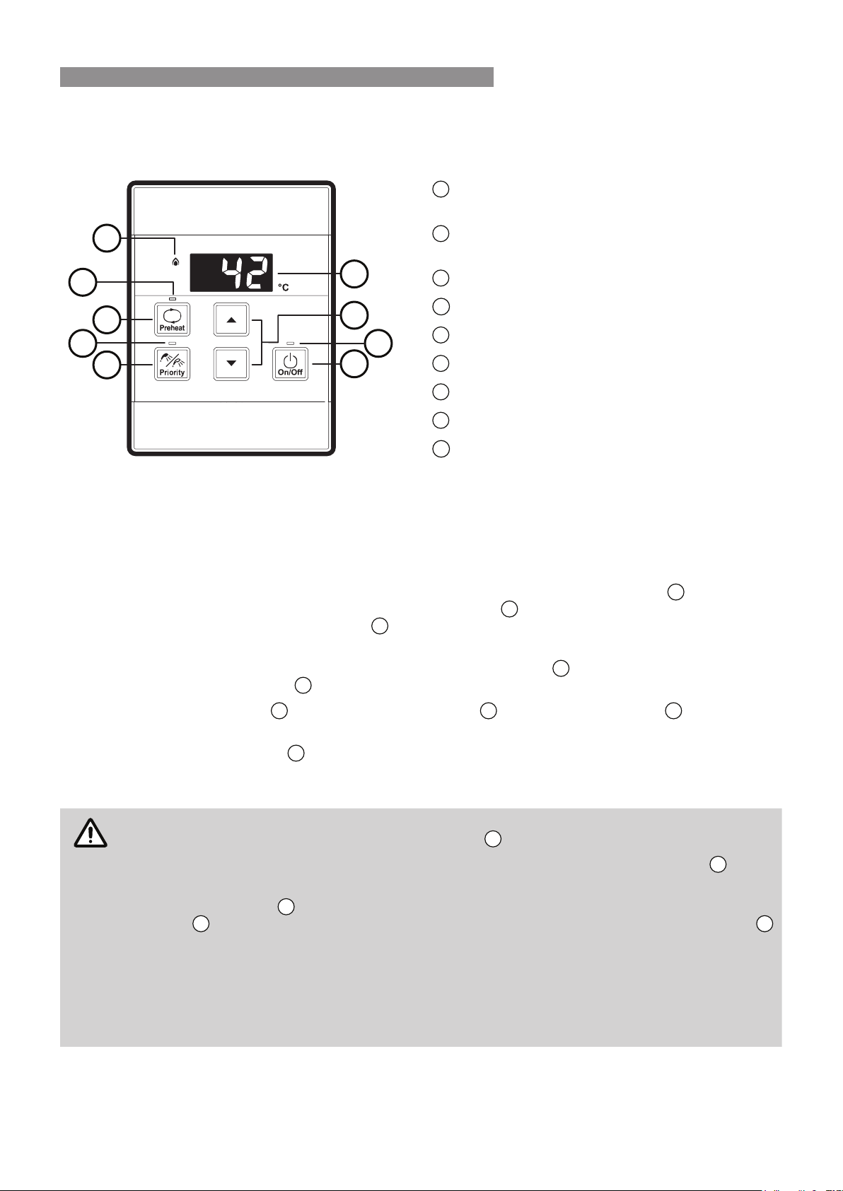
Indicates the temperature selected.
Error messages flash in event of a fault.
DIGITAL MONITOR
Used to select water temperature.
TEMPERATURE CONTROL BUTTONS
Indicates that the hot water heater is on.
WATER HEATER ON INDICATOR
Used to switch the water heater on and off.
ON/OFF BUTTON
Indicates that the Smartstart preheater (when fitted) is
activated.
PREHEAT INDICATOR
Used to start and stop the Smartstart preheat unit (when
fitted), See Smartstart Operation on page 11.
PREHEAT BUTTON
Indicates if this water controller is in control of water
delivery temperature.
CONTROLLER PRIORITY INDICATOR
Used to transfer control priority between water
controllers. The water controller with priority has
command of the hot water delivery temperature.
PRIORITY TRANSFER BUTTON
Indicates that a water heater is delivering hot water.
WATER HEATER 'IN USE' INDICATOR
HOTHOT
COLDCOLD
ON!ON!
WATER TEMPERATURE CONTROL
Rinnai 11 HW_CF OIM
SMARTSTART PRE-HEAT SYSTEM
The “Preheat” function works in conjunction with various Rinnai water heater models when the separately installed
and optional Rinnai “Smartstart®” module is installed.
2
7
1
8
5
3
6
4
9
1
Preheat Button
Used to start and stop Smartstart preheater
2
Preheat Indicator
Indicates that Smartstart preheater is activated*
3
Digital Monitor
4
2Q2ႇ%XWWRQ
5
Controller Priority Indicator
6
Temperature Control Buttons
7
Water Heater "In Use" Indicator
8
Priority Transfer Button
9
Water Heater On Indicator
Preheat Function
When the "Preheat" function is activated and used in accordance with these instructions, water in the pipework
connected between the water heater and the hot water outlets in your house is warmed before any outlets are
opened. This results in water savings and added convenience.
Preheat Operation
1. Ensure that the hot water unit is on (temperature digits are displayed in the digital monitor
3
). If more than
RQHZDWHUFRQWUROOHULV¿WWHGSUHVVWKH3ULRULW\7UDQVIHUEXWWRQ
8
to pass on priority to your desired water
controller. The "Controller Priority" indicator
5
ZLOOLOOXPLQDWHWRFRQ¿UPWKDWSULRULW\KDVEHHQDVVLJQHGWRWKLV
water controller and that the hot water unit is ready to deliver hot water.
2. Select the desired temperature using the "Temperature Control" buttons
6
until the required temperature is
displayed in the digital monitor
3
.
3. Press the "Preheat" button
1
once. The "Preheat" indicator
2
and the "In Use" indicator
7
will illuminate,
signifying that the preheat system has been activated.
4. Wait for the "In Use" indicator
7
WRJRRXWWKLVPD\WDNHWRPLQXWHV:KHQWKLVKDSSHQVLWVLJQL¿HVWKDW
the water in the pipework has now been pre-warmed and is ready for delivery, and that a hot water tap can
now be opened.
NOTE
7KHZDLWLQJWLPHPD\EHORQJHURUVKRUWHUGHSHQGLQJRQ\RXUSDUWLFXODULQVWDOODWLRQFRQ¿JXUDWLRQ
For best results always wait for the "In Use" indicator
7
to go out before opening a hot water tap.
The preheat function is cancelled 5 minutes after activation and the "Preheat" indicator
2
will go
out. This is to conserve energy. To reactivate, simply repeat steps 2-4 above.
If the "Preheat" button
1
is pressed and the 'Smartstart' preheat unit is not installed, the "Preheat"
indicator
2
will still light however there will be no preheat function. The "Preheat" indicator
2
ZLOOJRRXWDIWHUDVKRUWWLPHDQGZLOOQRWDႇHFWWKHRWKHUIXQFWLRQVRIWKHZDWHUFRQWUROOHURUZDWHU
heater.
:KHQ GHOX[H %DWKURRP ZDWHU FRQWUROOHUV DUH ¿WWHG DIWHU XVLQJ WKH 6KRZHU 6DYHU %DWK )LOO
function wait 30 seconds before activating the 'Preheat' function. Attempting to use the 'Preheat'
function earlier will result in voice prompts being repeated until the system is reset. The system
FDQEHUHVHWE\SUHVVLQJWKH2Q2ႇEXWWRQWZLFH
Water Controller Functions
Water controller functions such as temperature control and transfer of priority between multiple controllers are not
DႇHFWHGE\WKHRSHUDWLRQRIWKHSUHKHDW6XFKIXQFWLRQVDUHGHVFULEHGLQWKHDSSOLFDEOHVHFWLRQVRIWKLVPDQXDO
WATER TEMPERATURE CONTROL

Rinnai 12 HW_CF OIM
ERROR CODES
<RXU5LQQDLJDVFRQWLQXRXVÀRZZDWHUKHDWHUVKDVDVHOIGLDJQRVWLFFDSDELOLW\,IDIDXOWRFFXUVDQ(UURU&RGHZLOO
ÀDVKRQWKHGLJLWDOPRQLWRURI\RXUZDWHUFRQWUROOHUVRURQWKHVWDWXVPRQLWRURQWKHIURQWFRYHURIWKHZDWHUKHDWHU
7KLVDVVLVWVZLWKGLDJQRVLQJWKHIDXOWDQGPD\HQDEOH\RXWRRYHUFRPHDSUREOHPZLWKRXWDVHUYLFHFDOO3OHDVH
TXRWHWKHFRGHGLVSOD\HGZKHQHQTXLULQJDERXWVHUYLFH
0RGHOV,Q¿QLW\(QYLUR,Q¿QLW\(QYLUR%%%GRQRWKDYHD³6WDWXV0RQLWRU´
Code Description Remedy
- 1RWLFHDEOHUHGXFWLRQLQZDWHUÀRZ ,QOHWZDWHU¿OWHUQHHGVWREHFOHDQHG6HUYLFHFDOO
03
3RZHULQWHUUXSWLRQGXULQJ%DWK¿OO
:DWHUZLOOQRWÀRZRQSRZHUUHLQVWDWHPHQW
7XUQRIIDOOKRWZDWHUWDSV3UHVV2Q2IIWZLFH
10
$LULQWDNHRUÀXHEORFNHG 6HUYLFH&DOO
11
1RLJQLWLRQ1RJDVVXSSO\ &KHFNJDVLVWXUQHGRQDWZDWHUKHDWHUDQGJDVPHWHURUF\OLQGHU
12
)ODPH)DLOXUH/RZJDVÀRZ
&KHFNJDVLVWXUQHGRQDWZDWHUKHDWHUDQGJDVPHWHURUF\OLQGHU
&KHFNWKHUHDUHQRREVWUXFWLRQVWRWKHÀXHRXWOHW
14
5HPDLQLQJ)ODPH6DIHW\'HYLFH 6HUYLFH&DOO
16
2YHU7HPSHUDWXUH:DUQLQJ 6HUYLFH&DOO
19
(OHFWULFDO(DUWK&KHFN)DXOW 6HUYLFH&DOO
21
,QFRUUHFW'LSVZLWFK6HWWLQJ'HWHFWHG ,QVWDOOHUWRFKHFN'LSVZLWFK6HWWLQJV6HUYLFH&DOO
25
1HXWUDOLVHU7DQN6HQVRU)DXOW 6HUYLFH&DOO
32
2XWJRLQJ:DWHU7HPSHUDWXUH6HQVRU)DXOW 6HUYLFH&DOO
33
+HDW([FKDQJHU7KHUPLVWRU)DXOW 6HUYLFH&DOO
34
&RPEXVWLRQ$LU7HPSHUDWXUH6HQVRU)DXOW 6HUYLFH&DOO
41
$PELHQW7HPSHUDWXUH6HQVRU)DXOW 6HUYLFH&DOO
52
*DV0RGXODWLQJ9DOYH)DXOW 6HUYLFH&DOO
61
&RPEXVWLRQ)DQ)DXOW 6HUYLFH&DOO
65
:DWHU)ORZ&RQWURO)DXOW
'RHVQRWVWRSÀRZSURSHUO\
6HUYLFH&DOO
66
%\SDVV)ORZ&RQWURO)DXOW 6HUYLFH&DOO
70
0LFURSURFHVVRU)DXOW 6HUYLFH&DOO
71
0LFURSURFHVVRU)DXOW 6HUYLFH&DOO
72
0LFURSURFHVVRU)DXOW 6HUYLFH&DOO
92
1HXWUDOLVHU:DUQLQJ 6HUYLFH&DOO
lc
6FDOHEXLOGXSLQVLGHWKHKHDWH[FKDQJHU 6HUYLFH&DOO
SE
&DVFDGH&RQQHFWLRQ)DLOXUH 6HUYLFH&DOO
:LUHOHVVZDWHUFRQWUROOHUZKHQ¿WWHGLV2XWRI5DQJH
GXHWRWKHGLVWDQFHIURPWUDQVFHLYHURUDQREVWUXFWLRQ
0RYHZLUHOHVVZDWHUFRQWUROOHURUWUDQVFHLYHURUUHPRYHWKH
REVWUXFWLRQ
NOTE
6RPHIDXOWFRGHVDUHPRGHOVSHFL¿FDQGVRQRWDOOFRGHVZLOOGLVSOD\RQDOOPRGHOV
In the majority of cases, you may be able to clear the Error Code simply by turning the hot water
WDS2))WKHQ21DJDLQ,IWKLVGRHVQRWFOHDUWKH(UURU&RGHWU\SXVKLQJWKH2Q2ႇEXWWRQ2))
WKHQ21DJDLQRUWXUQLQJWKHSRZHUIRUXQLW2))ZDLWLQJVHFRQGVDQGWKHQ21DJDLQ,IWKH
Error Code still remains, contact Rinnai for advice.
TROUBLE SHOOTING
Rinnai 13 HW_CF OIM
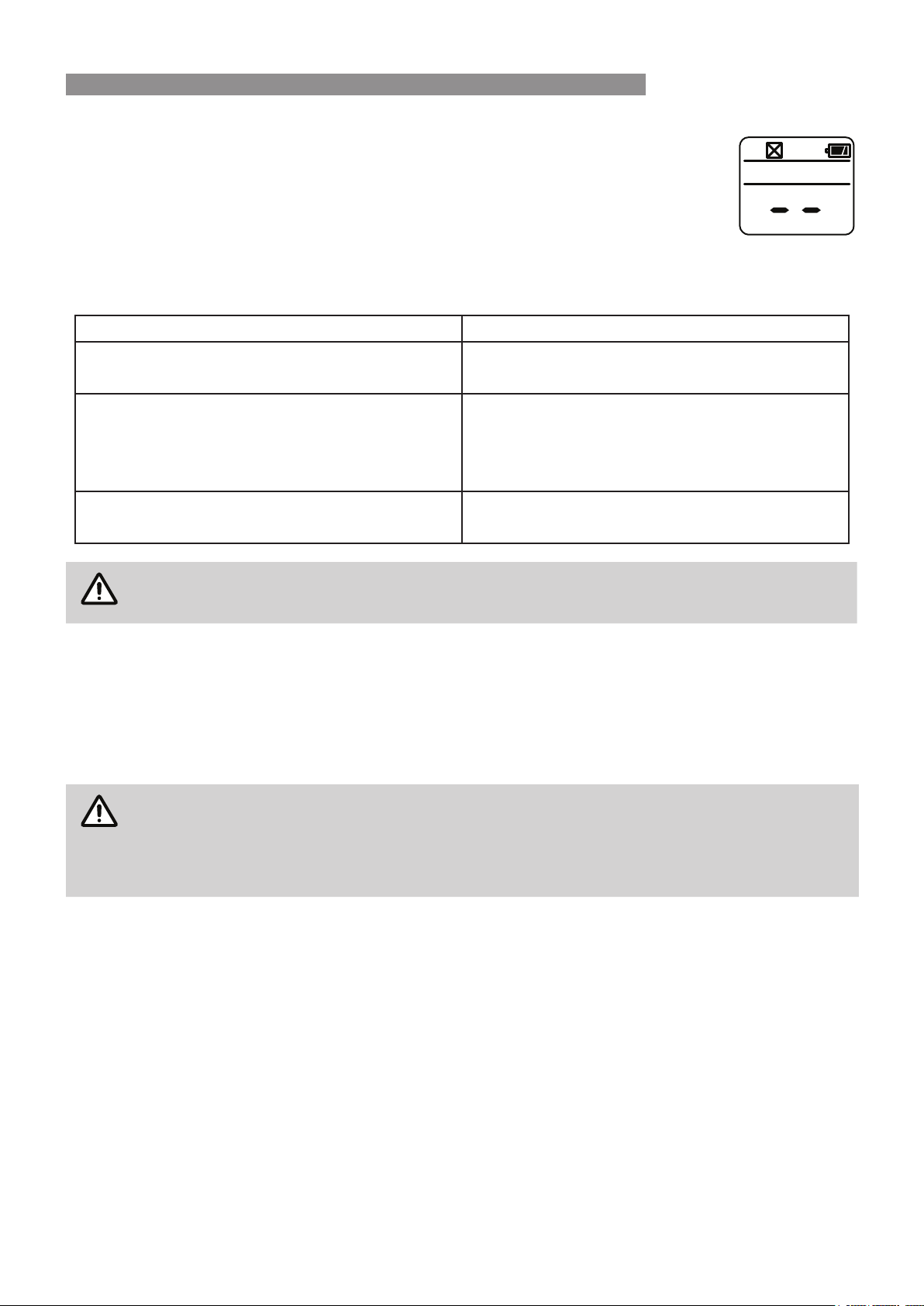
1RSRZHUGLVSOD\:LUHOHVV:DWHU&RQWUROOHUZKHQÀWWHG
:KHQSRZHUWRWKHZDWHUKHDWHULVGLVFRQQHFWHGWKH/&'RIDOOZLUHOHVVZDWHUFRQWUROOHUVZLOO
GLVSOD\DVVKRZQWRWKHULJKW
&KHFNWKDWWKHSRZHULVDYDLODEOHDQGWKDWWKHZDWHUKHDWHULVSOXJJHGLQZLWKWKHSRZHUSRLQW
WXUQHGµRQ¶
Troubleshooting Without Water Controllers
,I \RX KDYH QR ZDWHU FRQWUROOHUV DQG H[SHULHQFH WKH IROORZLQJ V\PSWRPV FDUU\ RXW WKHVH VXJJHVWLRQV ,I WKH
V\PSWRPFRQWLQXHVFRQWDFW5LQQDLIRUDGYLFH
'HVFULSWLRQ 5HPHG\
7KHXQLWGRHVQRWDWWHPSWWRVWDUWDWDOO
&KHFNWKHSRZHULVRQDWWKHXQLW
&KHFNWKHLVRODWLRQYDOYHVDWWKHXQLWDUHRSHQ
7KHXQLWVWDUWVWKHQVKXWVGRZQLPPHGLDWHO\
&KHFNWKHSRZHULVVWLOORQ
&KHFNWKHJDVLVRODWLRQYDOYHVDWWKHXQLWDQGWKHJDV
PHWHUDUHIXOO\RSHQ
2SHQ\RXUKRWZDWHUWDSIXOO\
7KHXQLWVWDUWVWKHQWKHZDWHUJRHVFROG
&KHFNWKHSRZHULVVWLOORQ
2SHQ\RXUKRWZDWHUWDSIXUWKHU
NOTE
)DXOWV FDXVHG E\ LQVXႈFLHQW JDV VXSSO\ LQVXႈFLHQW ZDWHU VXSSO\ JDV TXDOLW\ ZDWHU TXDOLW\
installation errors or operation errors are NOT covered by the Rinnai warranty. Refer to separate
warranty booklet for details.
SERVICE
:LUHGDQGZLUHOHVVZDWHUFRQWUROOHUVWUDQVFHLYHUVDQGZDWHUKHDWHUVGRQRWFRQWDLQXVHUVHUYLFHDEOHSDUWVDQG
PXVWRQO\EHVHUYLFHGDQGUHSDLUHGE\DQDXWKRULVHGSHUVRQ
5LQQDLKDVD6HUYLFHDQG6SDUH3DUWVQHWZRUNZLWKSHUVRQQHOZKRDUHIXOO\WUDLQHGDQGHTXLSSHGWRJLYHWKHEHVW
VHUYLFHRQ\RXU5LQQDLDSSOLDQFH,I\RXUDSSOLDQFHUHTXLUHVVHUYLFHSOHDVHFDOORXU1DWLRQDO+HOS/LQHRUWKH+RW
:DWHU6HUYLFH/LQHFRQWDFWQXPEHUVIRUZKLFKDUHRQWKHEDFNFRYHURIWKLVPDQXDO
NOTE
When making a service enquiry, having both the model and serial numbers available, will help our
VWDႇTXLFNO\LGHQWLI\\RXUDSSOLDQFHDQGEHWWHUDWWHQGWR\RXUQHHGV
This information should have been copied to the "Installation Record" on page 31 by your
installer, however if this is not the case, the information can also be found on the data plate
located on the left hand side of the appliance.
5LQQDLUHFRPPHQGVWKDWWKLVDSSOLDQFHEHVHUYLFHGHYHU\\HDUV
TROUBLE SHOOTING

Rinnai 14 HW_CF OIM
Operation Table of Contents 3
*HQHUDO,QVWDOODWLRQ,QIRUPDWLRQ
Regulations ........................................................................................................................................................................ 16
Applicable Models ............................................................................................................................................................. 16
Appliance Location ............................................................................................................................................................ 16
Outdoor Models ............................................................................................................................................................... 16
Indoor Models ................................................................................................................................................................. 16
Mounting Of Appliance .................................................................................................................................................... 17
Service Connection Points ............................................................................................................................................. 17
Pipe Sizing ...................................................................................................................................................................... 17
Water Supply ................................................................................................................................................................... 17
Altitude Setting REU-VCM ONLY .................................................................................................................................... 18
Altitude Setting REU-AM3237 ONLY .............................................................................................................................. 18
Hot Water Delivery Temperature ...................................................................................................................................... 19
,QVWDOODWLRQ&RQ¿JXUDWLRQV ............................................................................................................................................... 19
Flueing 20
Appliance Flue Terminal ................................................................................................................................................... 20
Horizontal Obstructions ................................................................................................................................................... 21
Sideways Flue Diverter - All models except REU-VCM .................................................................................................. 21
Multiple Appliance Installations ....................................................................................................................................... 21
,Q¿QLW\L+'L,QWHUQDO0RGHOV&R$[LDO)OXH ............................................................................................................... 22
Basic methods of installation .......................................................................................................................................... 22
Flue Length Dipswitches ................................................................................................................................................. 22
Multiple Terminal Installations ......................................................................................................................................... 22
5(8(0RGHO1HXWUDOLVHU7DQN'UDLQ
,PSRUWDQW&RQVLGHUDWLRQV)RU1HXWUDOLVHU'UDLQ3LSH.................................................................................................... 23
Length & Changes Of Direction ...................................................................................................................................... 23
Installation Method ............................................................................................................................................................ 23
Interconnection Of Condensate / Neutraliser Drain Lines ............................................................................................... 24
Common Stack Discharge .............................................................................................................................................. 24
Tundish Drain Lines ........................................................................................................................................................ 24
Areas Subject To Freezing .............................................................................................................................................. 24
INSTALLATION TABLE OF CONTENTS

Rinnai 15 HW_CF OIM
Water Controller Installation 25
*HQHUDO,QIRUPDWLRQ........................................................................................................................................................... 25
Master / Sub Water Controllers & Associated Temperatures .......................................................................................... 25
Water Controllers Limitations .......................................................................................................................................... 25
Location ........................................................................................................................................................................... 26
Communication Cables ................................................................................................................................................... 26
Joining Communication Cables (REU-A / REU-AM) ....................................................................................................... 26
Connecting Communication Cable(s) With 'Ezi connect' (REU-A / REU-AM) ................................................................27
Connecting Communication Cables to Mini-Plug (REU-E & REU-VCM) ........................................................................ 27
Connecting Communication Cables to PCB (REU-E & REU-VCM) ................................................................................ 28
Universal Water Controller (MC-601Q) Installation ........................................................................................................ 28
Additional Programming & Activation Requirements ....................................................................................................... 29
Commissioning 30
Testing ................................................................................................................................................................................ 30
Delivery Temperature ........................................................................................................................................................ 30
50°C Compliant Models .................................................................................................................................................. 30
For All Other Models ...................................................................................................................................................... 30
*DV3UHVVXUH6HWWLQJ ....................................................................................................................................................... 31
Wiring Diagram .................................................................................................................................................................. 31
Commissioning Check List ............................................................................................................................................... 31
Installation Record ............................................................................................................................................................ 31
6SHFL¿FDWLRQV
Table 1. Supply, Flow rates, Weights & Service Connections ....................................................................................... 32
Table 2. Maximum Delivery Temperatures ...................................................................................................................... 33
7DEOH$SSOLDQFH'LPHQVLRQV,Q¿QLW\(QYLUR,Q¿QLW\L+' .................................................................................. 34
Table 4. Appliance Dimensions - B Series & Universal Water Controller ..................................................................... 37
Table 5. Other Accessories ............................................................................................................................................... 38
Contacts 40
INSTALLATION TABLE OF CONTENTS

Rinnai 16 HW_CF OIM
WARNING
,167$//$7,21 6(59,&( $1' 5(029$/ MUST %( %< $1 $335235,$7(/< /,&(16('
75$'(63(5621ONLY.
,WLVWKHLQVWDOOHU¶VUHVSRQVLELOLW\WRHQVXUHDOOFXUUHQW$61=6UHTXLUHPHQWVDUHPHW
Remove transit protection. Check for damage, if any is found DO NOT install and contact supplier.
REGULATIONS
This appliance must be installed in accordance with:
•
Current AS/NZS 3000, AS/NZS 3500 and AS/NZS 5601
•
Rinnai Installation Instructions
•
Plumbing Code of Australia (PCA)
•
Local regulations and municipal building codes including local OH&S requirements
APPLICABLE MODELS
7KHVH,QVWDOODWLRQ,QVWUXFWLRQVDSSO\RQO\WRWKH5LQQDLJDVFRQWLQXRXVÀRZZDWHUKHDWHUPRGHOVWKDWDUHOLVWHGRQ
the cover page of this manual.
APPLIANCE LOCATION
This appliance MUST BESODFHGDVFORVHDVSUDFWLFDEOHWRWKHPRVWIUHTXHQWO\XVHGKRWZDWHURXWOHWRURXWOHWVWR
PLQLPLVHWKHGHOD\WLPHIRUKRWZDWHUGHOLYHU\)RULQVWDOODWLRQVZKHUHWKHGLVWDQFHEHWZHHQWKHZDWHUKHDWHUDQG
WKHRXWOHWVLVFRQVLGHUDEOHDÀRZDQGUHWXUQV\VWHPRUWKH5LQQDL6PDUWVWDUWV\VWHPFDQEHXVHGZKLFKPLQLPLVH
WKHZDLWLQJWLPHIRUKRWZDWHUGHOLYHU\
$OWHUQDWLYHO\ PXOWLSOH DSSOLDQFHV FDQ EH VWUDWHJLFDOO\ SODFHG WR VHUYH RXWOHWV ZLWK PLQLPDO GHOD\ WLPH &RQWDFW
Rinnai for further information.
$Q$&9$PSHDUWKHGSRZHUSRLQWMUST BE provided adjacent to the appliance. For outdoor installations
WKLVSRZHUSRLQWMUST BE ZHDWKHUSURRI,WMUST BEFOHDURIWKHJDVDQGZDWHUFRQQHFWLRQVWRWKHDSSOLDQFH
DQGDOVRWKHÀXHH[KDXVWDQGZDWHUSUHVVXUHUHOLHIYDOYH7KHSRZHUFRUGRIWKHDSSOLDQFHLV0HWUHVORQJ
This appliance MUST BEPRXQWHGRQDYHUWLFDOVWUXFWXUHZLWKWKHZDWHUDQGJDVFRQQHFWLRQVRQWKHXQGHUVLGH
SRLQWLQJGRZQZDUGV)RUDSSOLDQFHVLQVWDOOHGRQHOHYDWHGVWUXFWXUHVRUXQGHUÀRRUVVSHFL¿FUHTXLUHPHQWVDSSO\
Refer to AS/NZS 5601 Section 6 for details.
All appliances MUST BELQVWDOOHGWRHQVXUHDFFHVVFDQEHJDLQHGZLWKRXWKD]DUGRUXQGXHGLႈFXOW\IRULQVSHFWLRQ
UHSDLUUHQHZDORURSHUDWLRQDOSXUSRVHV6XႈFLHQWFOHDUDQFHVVKDOODOORZDFFHVVWRDQGUHPRYDORIDOOVHUYLFHDEOH
FRPSRQHQWV$SSOLDQFHVVKRXOGQRWEHPRXQWHGKLJKHUWKDQPHWUHVDERYHWKHJURXQGRUÀRRUOHYHOXQOHVV
WKHFXVWRPHUFDQDUUDQJHSHUPDQHQWDQGVDIHDFFHVVRUFDQSURYLGHDQRWKHUPHDQVRIDFFHVVIRUH[DPSOHE\
means of scissor or boom lifts or other approved safe access equipment that is acceptable to local authorities.
This appliance 0867127EHXVHGDVDGRPHVWLFVSDRUVZLPPLQJSRROKHDWHU
Models other than REU-VCM and REU-AM3237 are suitable for installation locations up to 1000 metres above sea
level and are 127 suitable for alpine areas.
REU-VCM and REU-AM3237 models are suitable for installation locations higher than 1000 metres above sea
level such as alpine areas, refer to "Altitude Setting REU-VCM ONLY" and "Altitude Setting REU-AM3237 ONLY"
on page 18 or further information.
Outdoor Models
This appliance is designed for ‘Outdoor’ Installation only. As such, it MUST BE located in an above ground open
DLUVLWXDWLRQZLWKQDWXUDOYHQWLODWLRQZLWKRXWVWDJQDQWDUHDVZKHUHJDVOHDNDJHDQGSURGXFWVRIFRPEXVWLRQDUH
UDSLGO\GLVSHUVHGE\ZLQGDQGQDWXUDOFRQYHFWLRQ
/RFDWLRQRIWKHDSSOLDQFHÀXHWHUPLQDOMUST BELQDFFRUGDQFHZLWK6HFWLRQDQG)LJXUHRI$61=6$Q
H[WUDFWLQSDUWKDVEHHQUHSURGXFHGLQWKH$SSOLDQFH)OXH7HUPLQDOVHFWLRQRIWKHVHLQVWUXFWLRQVRQSDJH
Indoor Models
This appliance is designed for ‘Indoor’ installation only. It may be installed ‘Outdoors’ in an enclosure if the
UHTXLUHPHQWVRI$61=66HFWLRQDUHVDWLV¿HG$QHQFORVXUHLVGH¿QHGDVDFRPSDUWPHQWHQFORVHGDUHD
RUSDUWLWLRQHGRႇVSDFHSULPDULO\XVHGIRUWKHLQVWDOOLQJRIWKHDSSOLDQFH
,ILQVWDOOHGLQDQHQFORVXUHHLWKHU,QWHUQDOO\RU([WHUQDOO\WKHORFDWLRQVKRXOGEHYHQWLODWHGWRDOORZJDVWRGLVVLSDWH
GENERAL INSTALLATION INFORMATION

Rinnai 17 HW_CF OIM
,IWKHZDWHUKHDWHULVLQVWDOOHGLQDFRQFHDOHGORFDWLRQSURYLVLRQVMUST BE made for the safe disposal of any
OHDNLQJZDWHUIURPWKHZDWHUKHDWHUWRDYLVLEOHORFDWLRQ
Rinnai internal models described in this manual MUSTXVHWKH&R$[LDO5LQQDL))ÀXHFRPSRQHQWV7KHXVHRI
QRQ5LQQDL))ÀXHFRPSRQHQWVPD\UHVXOWLQDGDQJHURXVVLWXDWLRQDQGYLRODWHVUHJXODWLRQV7KHPD[LPXP))ÀXH
OHQJWKLVPHWUHVUHIHUWRWKH))ÀXHLQVWDOODWLRQPDQXDOIRUÀXHFRQ¿JXUDWLRQRSWLRQV
This appliance MUST BEORFDWHGVRWKDWWKHÀXHWHUPLQDOH[LWVWKHEXLOGLQJDWDVXLWDEOHSRLQWWKHKRUL]RQWDOZDOO
FFWALLTERM or vertical (roof) FFROOFCOWL terminals are available for this purpose. The location of these
terminals MUST BELQDFFRUGDQFHZLWK6HFWLRQDQG)LJXUHRI$61=6$QH[WUDFWLQSDUWKDVEHHQ
reproduced in the "Appliance Flue Terminal" section of these instructions on page 20.
Mounting Of Appliance
7KHZDOORUVWUXFWXUHRQZKLFKWKHXQLWVDUHWREHPRXQWHGMUST BEFDSDEOHRIVXSSRUWLQJWKHVHZHLJKWVDQG
WKH DVVRFLDWHG SLSHZRUN 5HIHU WR 7DEOH 6XSSO\ )ORZ UDWHV :HLJKWV 6HUYLFH &RQQHFWLRQV RQ SDJH
IRUVSHFL¿FPRGHOZHLJKWV
(QVXUHWKDWVXLWDEOH¿[LQJVFUHZVRUEROWVDUHXVHGWRVHFXUHWKHXQLWVWRWKHZDOOLQDFFRUGDQFHZLWK$61=6
section 6. Wooden plugs shall 127 be used.
7KHWRSEUDFNHWKDVDNH\KROHVORWVRWKDWWKHDSSOLDQFHFDQEHSRVLWLRQHGE\KDQJLQJLWRQRQHVFUHZRQFHLQ
SRVLWLRQWKHDSSOLDQFHFDQWKHQEHIXOO\VHFXUHGZLWKWKHDSSOLFDWLRQRIIXUWKHUDSSURSULDWH¿WWLQJV
7KHDSSOLDQFHFDQEHPRXQWHGGLUHFWO\DJDLQVWWKHZDOORUVWUXFWXUH7KHUHLVQRQHHGWRXVHQRQFRPEXVWLEOH
VKHHWLQJRUOHDYHDQDLUJDSEHWZHHQWKHDSSOLDQFHEDFNSDQHODQGWKHZDOORUVWUXFWXUHWRPHHWWKHWHPSHUDWXUH
KD]DUGUHTXLUHPHQWVRI$61=6
Service Connection Points
5HIHUWR7DEOH6XSSO\)ORZUDWHV:HLJKWV6HUYLFH&RQQHFWLRQVRQSDJHIRUPRGHOVSHFL¿FFRQQHFWLRQ
¿WWLQJGLPHQVLRQGHWDLOV
$Q$SSURYHGIXOOÀRZLVRODWLRQYDOYHDQGGLVFRQQHFWLRQXQLRQMUST BE¿WWHGWRWKHFROGZDWHUDQGJDVLQOHWV
$QRQUHWXUQYDOYHLVQRWUHTXLUHGRQWKHZDWHULQOHWXQOHVVUHTXLUHGE\ORFDOUHJXODWLRQV,VRODWLRQ9DOYHVMUST
127EH¿WWHGGLUHFWO\WRWKHDSSOLDQFH
,IPD\EHQHFHVVDU\WR¿WDWHPSHUDWXUHOLPLWLQJGHYLFHIRUGHOLYHU\WRDUHDVXVHGSULPDULO\IRUWKHSXUSRVHVRI
personal hygiene. Refer to "Hot Water Delivery Temperature" on page 19.
3XUJHJDVDQGFROGZDWHUVXSSO\OLQHVWRUHPRYHDLUDQGVZDUIEHIRUH¿QDOFRQQHFWLRQRIWKHDSSOLDQFH6ZDUILQ
HLWKHUWKHJDVRUZDWHUVXSSOLHVPD\FDXVHGDPDJH
Pipe Sizing
,IWKHJDVSLSHVL]LQJLVLQVXႈFLHQWWKHFXVWRPHUZLOOQRWJHWWKHIXOOSHUIRUPDQFHEHQH¿W*DVSLSHVL]LQJMUST
FRQVLGHUWKHJDVLQSXWWRWKLVDSSOLDQFHDVZHOODVDOOWKHRWKHUJDVDSSOLDQFHVLQWKHSUHPLVHV7KHJDVPHWHUDQG
regulator MUST BEVSHFL¿HGIRUWKLVJDVUDWH
$QDSSURYHGVL]LQJFKDUWVXFKDVWKHRQHLQ$61=6VKRXOGEHXVHG5HIHUWR7DEOH6XSSO\)ORZUDWHV
:HLJKWV6HUYLFH&RQQHFWLRQVRQSDJHIRUPRGHOVSHFL¿FJDVFRQVXPSWLRQGHWDLOV
:DWHUSLSHVL]LQJDQGOD\RXWVKRXOGEHSHUIRUPHGLQDFFRUGDQFHZLWK$61=6$OOKRWZDWHUSLSHZRUNVKRXOG
EHLQVXODWHGWRRSWLPLVHSHUIRUPDQFHDQGHQHUJ\HႈFLHQF\
Water Supply
7KHDSSOLDQFHLVLQWHQGHGWREHSHUPDQHQWO\FRQQHFWHGWRWKHZDWHUPDLQV
5HIHUWR7DEOH6XSSO\)ORZUDWHV:HLJKWV6HUYLFH&RQQHFWLRQVRQSDJHIRUPRGHOVSHFL¿FRSHUDWLRQDO
ZDWHUSUHVVXUHOLPLWDWLRQV$SSURYHGSUHVVXUHOLPLWLQJYDOYHVPD\EHUHTXLUHGLIWKHµ0D[LPXP¶UDWHGZDWHUVXSSO\
SUHVVXUHVLQ7DEOHDUHH[FHHGHG7RDFKLHYHWKHUDWHGÀRZWKHµ0LQLPXP¶ZDWHUVXSSO\SUHVVXUHVLQ7DEOH
PXVWEHVXSSOLHG7KHZDWHUKHDWHUVZLOORSHUDWHDWORZHUSUHVVXUHVEXWZLOOQRWDFKLHYHWKHUDWHGÀRZ&RQWDFW
5LQQDLIRUµJUDYLW\IHG¶RUµORZSUHVVXUH¶LQVWDOODWLRQV
:DWHUFKHPLVWU\DQGLPSXULW\OLPLWVDUHGHWDLOHGXQGHUµ:DUUDQW\&RQGLWLRQV¶0RVWPHWURSROLWDQZDWHUVXSSOLHVIDOO
ZLWKLQWKHUHTXLUHPHQWV,I\RXDUHXQVXUHDERXW\RXUORFDOZDWHUTXDOLW\FRQWDFW\RXUZDWHUDXWKRULW\,IVOXGJHRU
IRUHLJQPDWWHULVSUHVHQWLQWKHZDWHUVXSSO\DVXLWDEOH¿OWHURUVWUDLQHULVUHTXLUHGLQWKHZDWHUVXSSO\WRWKHZDWHU
KHDWHUWRSUHYHQWXQZDUUDQWHGGDPDJHDQGORVVRISHUIRUPDQFH
GENERAL INSTALLATION INFORMATION
Rinnai 18 HW_CF OIM
Altitude Setting REU-VCM ONLY
IMPORTANT
REU-VCM models are suitable for installation locations higher than 1000 metres above sea level
such as alpine areas. To ensure proper appliance operation the installer MUST select one of the
two available altitude ranges for the appliance these are:
'DEFAULT' suitable for installation locations that are from 0 to 900 metres
above sea level.
'HIGH' suitable for installation locations that are from 901 to 1800 metres
above sea level, as would be typical of installations located in alpine areas.
Refer to "Commissioning Instructions" located inside the appliance front
cover for details.
OFF ON
DipSW1
6
OFF ON
DipSW2
6
Default
OFF ON
DipSW1
6
OFF ON
DipSW2
6
High
Altitude Setting REU-AM3237 ONLY
IMPORTANT
REU-AM3237 models are suitable for installation locations higher than 1000 metres above sea
level such as alpine areas. To ensure proper appliance operation the installer MUST select one of
the two available altitude ranges for the appliance these are:
'DEFAULT' suitable for installation locations that are from 0 to 900 metres
above sea level.
'HIGH' suitable for installation locations that are from 901 to 1800 metres
above sea level, as would be typical of installations located in alpine areas.
Refer to "Commissioning Instructions" located inside the appliance front
cover for details.
Default
Dipswitch
High
1
OFF ON
2
3
4
1
OFF ON
2
3
4
GENERAL INSTALLATION INFORMATION
Rinnai 19 HW_CF OIM
HOT WATER DELIVERY TEMPERATURE
WARNING
This appliance may deliver water at high temperature. Refer to the Plumbing Code of Australia
(PCA), local requirements and installation instructions to determine if additional delivery
temperature control is required.
Local regulations and or the requirements of AS/NZS 3500 MUST be addressed regarding the temperature
OLPLWDWLRQVRIKRWZDWHUVXSSOLHGWRDUHDVXVHGSULPDULO\IRUSHUVRQDOK\JLHQH7KHWHPSHUDWXUHRIZDWHUWRWKHVH
areas may be limited to 50°C or less. To ensure these regulations and or requirements are met the system MUST
EHLQVWDOOHGLQDFFRUGDQFHZLWKWKH,QVWDOODWLRQ&RQ¿JXUDWLRQVEHORZ
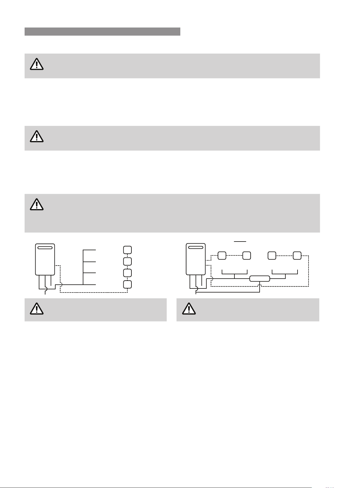
,QVWDOODWLRQ&RQÀJXUDWLRQV
WARNING
This appliance MUSTRQO\EHLQVWDOOHGLQDFFRUGDQFHZLWKWKHDFFHSWDEOHSOXPELQJFRQ¿JXUDWLRQV
VSHFL¿HGLQWKHVHLQVWUXFWLRQV)DLOXUHWRGRVRPD\UHVXOWLQFRQGLWLRQVZKHUHGHOLYHU\WHPSHUDWXUH
control is inadequate.
,IWKHDSSOLDQFHLVPDUNHGWRVWDWHWKDWLWGHOLYHUVZDWHUQRWH[FHHGLQJ&ORFDOUHJXODWLRQVPD\SHUPLWLQVWDOODWLRQ
ZLWKRXWD7HPSHUDWXUH/LPLWLQJ'HYLFH,QVWDOODWLRQVZLWKRXWD7HPSHUDWXUH/LPLWLQJ'HYLFHDUHVKRZQLQ'LDJUDP
EHORZ,I\RXDUHXQVXUHDERXW\RXUORFDOUHJXODWLRQVFRQWDFW\RXUUHJXODWLQJDXWKRULW\RU5LQQDL,IWKHDSSOLDQFH
is 127PDUNHGWRVWDWHWKDWLWGHOLYHUVZDWHUQRWH[FHHGLQJ&RU\RXUORFDOUHJXODWLRQVUHTXLUHLQVWDOODWLRQZLWK
D7HPSHUDWXUH/LPLWLQJ'HYLFHWKHQLQVWDOOWKHDSSOLDQFHLQDFFRUGDQFHZLWK'LDJUDPEHORZ
IMPORTANT
If the appliance is to deliver water primarily for the purposes of personal hygiene in an early
childhood centre, primary or secondary school, nursing home or a similar facility for the care of
\RXQJDJHGVLFNRUGLVDEOHGSHUVRQVDVGH¿QHGLQ$61=D7HPSHUDWXUH/LPLWLQJ'HYLFH
(TLD), such as a Tempering Valve may be required even if the appliance is set to 50º C or less. For
these types of applications contact Rinnai.
50º C
KITCHEN
Water controller
(optional)
Water controller
(optional)
Water controller
(optional)
Water controller
(optional)
LAUNDRY
BATHROOM
ENSUITE
+
2
7
&
2
/
'
*
$
6
Diagram 1 : 50°C Appliance
KITCHEN
Water controller
(optional)
Water controller
(optional)
LAUNDRY BATHROOM
Water controller
(optional)
Water controller
(optional)
ENSUITE
TLD
+
2
7
&
2
/
'
*
$
6
Diagram 2 : NOT a 50°C Appliance
NOTE
Minimum length of pipe from hot outlet
to nearest hot water tap 2 metres.
NOTE
TLD = Temperature Limiting Device.
8QLYHUVDO ZDWHU FRQWUROOHUV DUH DYDLODEOH DV DQ RSWLRQDO H[WUD DQG ZLOO IXQFWLRQ DV GHVFULEHG LQ WKH 2SHUDWLRQ
6HFWLRQRIWKLVPDQXDO5HIHUWR:DWHU&RQWUROOHUV/LPLWDWLRQVRQSDJHWRFRQ¿UPWKHPD[LPXPQXPEHUDQG
FRPELQDWLRQRIZDWHUFRQWUROOHUVWKDWFDQEH¿WWHG
)RU GHWDLOHG LQVWDOODWLRQ LQIRUPDWLRQ RI 8QLYHUVDO ZDWHU FRQWUROOHUV UHIHU WR WKH :DWHU &RQWUROOHU ,QVWDOODWLRQ
FKDSWHURIWKLVPDQXDOVWDUWLQJRQSDJH2SHUDWLRQDQG,QVWDOODWLRQLQIRUPDWLRQIRU'HOX[HDQG:LUHOHVVZDWHU
FRQWUROOHUVLVSURYLGHGZLWKWKHZDWHUFRQWUROOHUVRUYLVLWZZZULQQDLFRPDX
GENERAL INSTALLATION INFORMATION
Rinnai 20 HW_CF OIM
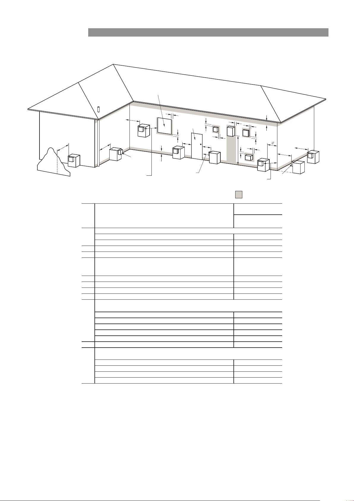
APPLIANCE FLUE TERMINAL
+RUL]RQWDO7HUPLQDO&OHDUDQFHV([WUDFWIURP$61=6
Min. Clearances
(mm)
For appliances up to 50 MJ/h input
200
For appliances over 50 MJ/h input
300
300* ecafrus rehto ro ynoclab a evoba ,dnuorg eht morFb
300* renroc lanretxe ro llaw nruter a tnor
Fc
d
From a gas meter (M) (see Note 5)
(see Clause 5.11.5.9 for vent terminal location of regulator)
(see Table 6.7 for New Zealand requirements)
1000
e
From an electricity meter or fuse box (P) † (see Note 5)
500
epip lios ro epip niard a morFf
g
Horizontally from any building structure* = or obstruction facing a terminal
500
h
From any other flue terminal , cowl, or combustion air intake *
300
Appliances up to 150 MJ/h input *
300
Appliances over 150 MJ/h input up to 200 MJ/h input *
300
Appliances over 200 MJ/h input up to 250 MJ/h input *
500
Appliances over 250 MJ/h input *
1500
All fan-assisted flue appliances, in the direction of discharge
1500
1000rewolb aps a gnidulcni ,telni r
ia lacinahcem a morFk
Space heaters up to 50 MJ/hr input
Other appliances up to 50 MJ/hr input
500
Appliances over 50 MJ/h input and up to 150 MJ/h input
1000
Appliances over 150 MJ/h input
1500
metI.feR
a
Below eaves, balconies and other projections:
FIGURE 6.2 (in-part) LOCATION OF FLUE TERMINALS OF BALANCED FLUE,
ROOM-SEALED, FAN-ASSISTED OR OUTDOOR APPLIANCES
n
j
Horizontally from an openable window, door, non-mechanical air inlet, or any other opening into a
building with the exception of sub-floor ventilation:
Vertically below an openable window, non-mechanical air inlet, or any other opening into a
building with the exception of sub-floor ventilation:
Where dimensions c, j or k cannot be achieved an equivalent horizontal distance measured
diagonally from the nearest discharge point of the terminal to the opening may be deemed by
the Technical Regulator to comply.
See Clause 6.9.4 for restrictions on a flue terminal under a covered area.
See Figure J3 for clearances required from a flue terminal to an LP Gas cylinder. A
flue terminal is considered to be a source of ignition.
For minimum clearances not addressed above acceptance should be obtained from the
Technical Regulator.
Minimum clearances d and e also apply to any combustion air intake openings of appliances.
1
2
3
4
5
* Unless appliance is certified for closer installation.
† Prohibited area below electricity meter or fuse box extends to ground level.
NOTES:
75
Shading indicates prohibited
area for flue terminals
LEGEND:
I = Mechanical air inlet
S = Structure
M = Gas meter
T = Flue terminal
P = Electricity meter or fuse box
Z = Fan -a ssi sted a ppl ian ce o nly
Direction of
discharge
See Note 1
See Note 1
Opening into
a building
T
T
T
T
T
T
T
C
M
d
d
e
e
h
j
j
j
n
b
f
a
h
P
Z
S
k
k
g
g
g
I
T
Door
Fan
assisted
150
FLUEING
Rinnai 21 HW_CF OIM
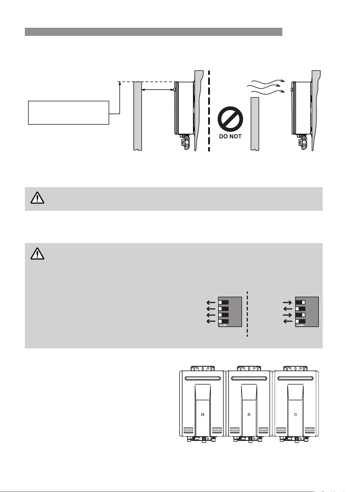
Horizontal Obstructions
$61=6µ*DV,QVWDOODWLRQV¶VWLSXODWHVDPLQLPXPKRUL]RQWDOFOHDUDQFHRIPPEHWZHHQDEXLOGLQJVWUXFWXUH
and obstruction facing the terminal.
)RUFRUUHFWRSHUDWLRQRI5LQQDLH[WHUQDOJDVFRQWLQXRXVÀRZZDWHUKHDWHUVVXFKDEXLOGLQJVWUXFWXUHMUST ‘obstruct’
the full front cover height of the appliance (for appliance dimensions, refer to "Table 3. Appliance Dimensions -
,Q¿QLW\ (QYLUR ,Q¿QLW\L +' RQ SDJH DQG 7DEOH$SSOLDQFH 'LPHQVLRQV % 6HULHV 8QLYHUVDO :DWHU
&RQWUROOHURQSDJHRUH[WHQGYHUWLFDOO\DERYHDQGEHORZWKHIURQWFRYHUDVVKRZQEHORZ
IMPORTANT
There MUST be NO partial obstructions to the front cover of the appliance or any other parts
of the appliance casing. This will avoid the appliance failing to operate under windy conditions.
Sideways Flue Diverter - All models except REU-VCM
:KHQD6LGHZD\V)OXH'LYHUWHULVWREH¿WWHGWKHLQVWDOOHUMUST also UHIHUWRWKHLQVWUXFWLRQVSURYLGHGZLWKWKH
6LGHZD\V)OXH'LYHUWHUDQGREVHUYHDOOWKHVSHFL¿FFOHDUDQFHVDQGZDUQLQJV
WARNING
CONTROL BOARD DIPSWITCH SETTING (NOT REU-VCM)
7KHVHFKDQJHVGRQWDSSO\WR5(8$0ZKHQD6LGHZD\V)OXH'LYHUWHULV¿WWHG
The installer MUST follow the Sideways Flue Diverter instructions of the "Commissioning Check
List" provided on the front cover of the appliance and the "Commissioning Instructions" located
in the inside the appliance front cover.
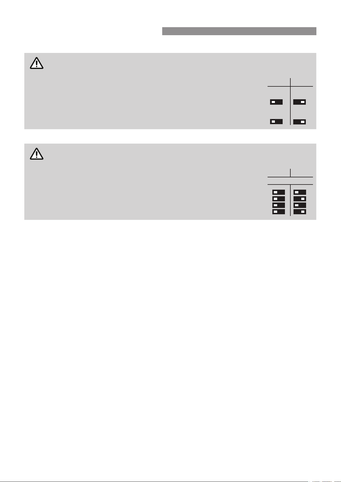
When delivered ex-factory ALL the
switches of the control board dipswitch
are set to OFF (left position).
:KHQ D 6LGHZD\V )OXH 'LYHUWHU LV ¿WWHG
the installer MUST set switches SW1
and SW3 to ON (right position) ONLY.
Improper setting of the switches will cause the appliance to operate incorrectly.
Multiple Appliance Installations
,QUHIHUHQFHWR+RUL]RQWDO7HUPLQDO&OHDUDQFHV([WUDFW
from AS/NZS 5601) dimension ‘h’ on page 20 does
QRWDSSO\ZKHQPXOWLSOH5LQQDLH[WHUQDOZDWHUKHDWHUVRI
the same model are installed on the same vertical face
ZLWKÀXHWHUPLQDOVDWWKHVDPHKHLJKW
Under these conditions appliances can abut each other
DVVKRZQOHIW&RQVLGHUWKHWRWDOJDVFRQVXPSWLRQRIDOO
DSSOLDQFHVDSSOLHVZKHQGHWHUPLQLQJRWKHUFOHDUDQFHV
For appliance dimensions, refer to "Table 3. Appliance
'LPHQVLRQV ,Q¿QLW\ (QYLUR ,Q¿QLW\L +' RQ SDJH
DQG 7DEOH $SSOLDQFH 'LPHQVLRQV % 6HULHV
Universal Water Controller" on page 37.
500mm
MINIMUM OBSTRUCTION
HEIGHT IS TO BE NO LESS
THAN TOP OF APPLIANCE
SW1 (OFF)
SW2 (OFF)
SW3 (OFF)
SW4 (OFF)
ON
1234
DipSW
SW1 (ON)
SW2 (OFF)
SW3 (ON)
SW4 (OFF)
ON
1234
DipSW
Factory Default Sideways Flue Diverter
FLUEING
Rinnai 22 HW_CF OIM
INFINITY-i / HD-i INTERNAL MODELS - CO-AXIAL FLUE
IMPORTANT
Rinnai internal models described in this manual MUST XVH WKH &R$[LDO 5LQQDL ))8 ÀXH
FRPSRQHQWV7KHXVHRIQRQ5LQQDL))8ÀXHFRPSRQHQWVPD\UHVXOWLQDGDQJHURXVVLWXDWLRQ
and violates regulations.
7KH ))8 ÀXH V\VWHP MUST be installed in accordance with the ‘Rinnai FFU Flue Installation
0DQXDO¶ZKLFKLVSURYLGHGZLWKWKH))8ÀXHWHUPLQDOFRPSRQHQWV)):$//7(50RU))522)&2:/
:KHUH WKH ÀXH OHQJWK H[FHHGV P HQVXUH WKDW D FRQGHQVDWH GUDLQ SLSH KDV EHHQ ¿WWHG LQ
accordance with the FFU Flue Installation Manual.
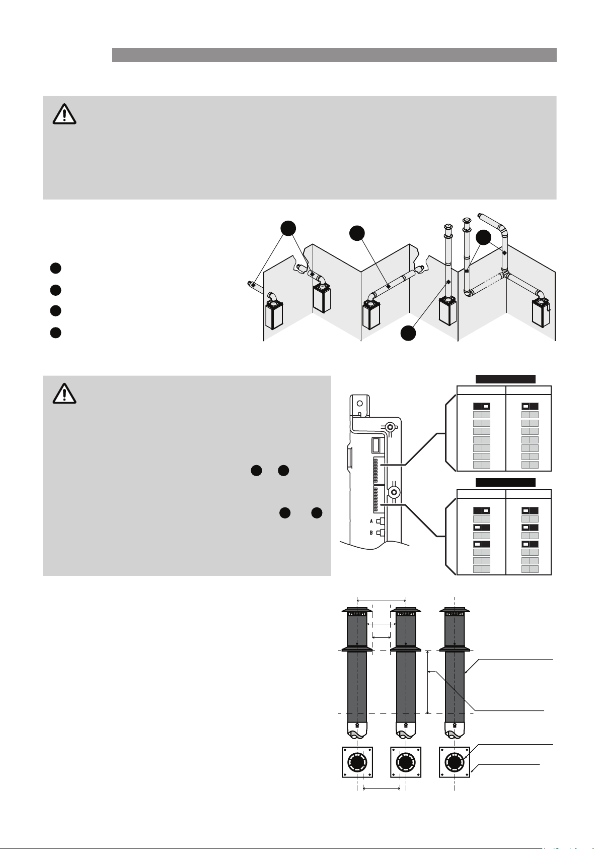
Basic methods of installation
7KHUH DUH IRXU EDVLF ÀXH LQVWDOODWLRQ
methods available, these are:
1
Direct Horizontal
2
Extended Horizontal
3
Vertical
4
Combined Vertical / Horizontal
Flue Length Dipswitches
IMPORTANT
Installations can consist of both horizontal and
vertical runs.
7KHPD[LPXPÀXHOHQJWKMUST NOT exceed 15
PHWUHVWKHWRWDOQXPEHURIEHQGVLQDQ\ÀXH
run MUST NOT exceed four, noting that each
EHQGLVHTXLYDOHQWWRPHWUHVRIÀXH
6KRUW ÀXH ,QVWDOODWLRQ PHWKRGV
1
&
3
, where
WKH WRWDO ÀXH GRHV NOT exceed 7 metres, the
6:RIERWK'LS6:'LS6:DUHVHWWR21
([WHQGHG ÀXH ,QVWDOODWLRQ PHWKRGV
2
&
4
,
ZKHUHWKHWRWDOÀXHOHQJWKH[FHHGVPHWUHVWKH
SW1 of both DipSW1 & DipSW2 are set to 'OFF'.
Refer to the 'Rinnai FFU Flue Installation Manual'
IRUIXOOGHWDLOVUHJDUGLQJÀXHOHQJWKVDQGEHQGV
Multiple Terminal Installations
The terminal clearances stated in AS/NZS 5601 do not apply
WRWKH5LQQDLLQWHUQDOJDVFRQWLQXRXVÀRZZDWHUKHDWHUV ZKHQ
they are installed side by side.
$*$FHUWL¿FDWLRQDOORZVIRUDPLQLPXPKRUL]RQWDOVHSDUDWLRQRI
PPIRUURRIWHUPLQDOVDQGPPIRUZDOOWHUPLQDOV
For all other appliance dimensions, refer to "Table 3. Appliance
'LPHQVLRQV,Q¿QLW\(QYLUR,Q¿QLW\L+' RQSDJHDQG
7DEOH$SSOLDQFH'LPHQVLRQV%6HULHV8QLYHUVDO:DWHU
Controller" on page 37.
1
2
3
4
DipSW1
DipSW2
OFF ON
1 2345678
OFF ON
1 2345678
OFF ON
1 2 3 4 5 678
FF
FF
OFF ON
1 2 3 4 5 678
FF
FF
Short Flue Extended Flue
Short Flue Extended Flue
DipSW1
DipSW2
275
150
85
195
FFWALLTERM
Minimum
Clearance
500
FFWPLATE
FFROOFCOWL
FLUEING
Rinnai 23 HW_CF OIM
7KH5(8(VHULHVZDWHUKHDWHUV,Q¿QLW\(QYLURDQG,Q¿QLW\(QYLURJHQHUDWHFRQGHQVDWHFRQWLQXRXVO\DWD
UDWHRIXSWROLWUHVSHUKRXUDVDE\SURGXFWRIKLJKO\HႈFLHQWJDVEXUQHUV\VWHP
7KLVFRQGHQVDWHKDVEHHQQHXWUDOLVHGE\SUH¿WWHG&RQGHQVDWH1HXWUDOLVHU.LW
7KHFRQ¿JXUDWLRQRIGUDLQOLQHVMUSTEHLQDFFRUGDQFHZLWKORFDOUHJXODWRU\UHTXLUHPHQWVDQGWKHUHTXLUHPHQWV
RI$61=6
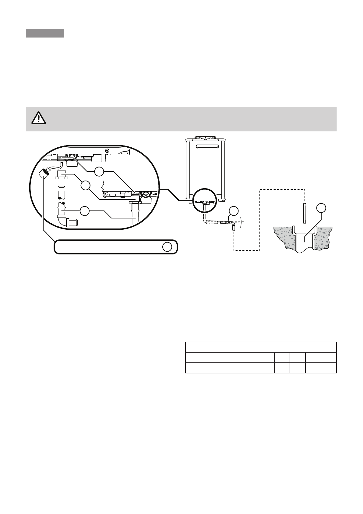
IMPORTANT CONSIDERATIONS FOR NEUTRALISER DRAIN PIPE
NOTE
7KHFRQWHQWRI$61=6µ7HPSHUDWXUH3UHVVXUH5HOLHIDQG([SDQVLRQ&RQWURO9DOYH'UDLQ
Lines’ has been used as a guide in preparing these considerations.
:DWHU KHDWHU GUDLQ RXWOHW FRQQHFWLRQ 5ò´ PP %63 PDOH &RQGHQVDWH 1HXWUDOLVHU GUDLQ RXWOHW
FRQQHFWLRQ´PP%63PDOHQ\ORQ1RWHWKHEODFNSODVWLFVKLSSLQJFDSMUST BEUHPRYHGIURPWKH
FRQGHQVDWHQHXWUDOLVHUGUDLQRXWOHWSULRUWRZDWHUKHDWHURSHUDWLRQ
3(5ò´%63PPIHPDOHWREDUEHGLUULJDWLRQV\VWHPFRQQHFWRU±PPRUHTXLYDOHQWSODVWLF¿WWLQJ
'UDLQSLSHDQG¿WWLQJVWRPDWFKLWHP
&RQWLQXRXVIDOORIDWOHDVWIURPZDWHUKHDWHUWRGLVFKDUJHSRLQW/HQJWKVDQGEHQGVLQDFFRUGDQFHZLWK
µ/HQJWK&KDQJHV2I'LUHFWLRQ¶WDEOHEHORZ
6XLWDEOHSRLQWV RIGLVFKDUJH DUH GHHPHG WR EH GUDLQV VHZHUV RU SLWV '2127 GLVFKDUJH RQWR HOHFWULFDO
FRQQHFWLRQVHDUWKVWDNHVFRSSHUSLSHVFRQFUHWHSDWKVRULQWRDSRQG
Length & Changes Of Direction
0D[LPXPOHQJWKDQGFKDQJHVRIGLUHFWLRQJUHDWHUWKDQ
VKRXOGEHDVIROORZV
/HQJWKVDQGFKDQJHVRIGLUHFWLRQ
0D[OHQJWK0HWUHV 87
0D[FKDQJHVRIGLUHFWLRQ! 3
INSTALLATION METHOD
D 7KHUHVKDOOEHQRWDSYDOYHRURWKHUUHVWULFWLRQVLQDQ\OLQH
E (DFKOLQHVKDOOIDOOFRQWLQXRXVO\IURPWKHYDOYHWRWKHDSSURYHGSRLQWRIGLVFKDUJH
F 'UDLQOLQHVVKDOOQRWGLVFKDUJHLQWRDVWRUDJHZDWHUKHDWHUVDIHWUD\
G 7KHHQGRIWKHGUDLQOLQHVKDOOEH
L QRWORZHUWKDQPPRUKLJKHUWKDQPPDERYHDQXQSDYHGVXUIDFHRU
LL QRWORZHUWKDQPPRUKLJKHUWKDQPPDERYHDJUDYHOSLWQRWOHVVWKDQPPLQGLDPHWHULQD
SDYHGVXUIDFH
H :KHUHGLVFKDUJLQJRYHUDWXQGLVKRUJXOO\WUDSGUDLQOLQHVVKDOOKDYHDQDLUJDSRIDVL]HDWOHDVWWZLFHWKH
GLDPHWHURIWKHGUDLQOLQH
B
A
C
2°
D
E
A
Remove cap from condensate drain outlet
REU-E MODEL NEUTRALISER TANK & DRAIN

5LQQDL HW_CF OIM
Interconnection Of Condensate / Neutraliser Drain Lines
&RQGHQVDWH1HXWUDOLVHUGUDLQOLQHVIURPPXOWLSOHZDWHUKHDWHUVPD\EHMRLQHGWRJHWKHUSURYLGHGWKH\FRQIRUP
ZLWKWKHUHTXLUHPHQWVRIWKH,QVWDOODWLRQ0HWKRGRQSDJH
Common Stack Discharge
:KHUHLQGLYLGXDOZDWHUKHDWHUVDUHLQVWDOOHGLQDPXOWLVWRUH\EXLOGLQJWKHFRQGHQVDWHQHXWUDOLVHUGUDLQOLQHVPD\
GLVFKDUJHLQWRDFRPPRQVWDFNVXEMHFWWRWKHIROORZLQJ
D 7KHGLVFKDUJHIURPWKHFRPPRQVWDFNLVWRDWXQGLVKKDYLQJDGLVFKDUJHOLQHWKDWLVQRWOHVVWKDQWKHVL]H
RIWKHFRPPRQVWDFNGLUHFWO\FRQQHFWHGWRD¿[WXUHWUDSDQGLQVWDOOHGLQFRQQHFWLRQZLWKDQ\DGMDFHQWVRLO
RUZDVWHVWDFN
E 7KHGLVFKDUJHSRLQWRIWKHFRPPRQVWDFNLVVXFKWKDWDQ\GLVFKDUJHLVUHDGLO\YLVLEOHDQGQRWFDXVHDQ\
QXLVDQFH
F 7KHFRPPRQVWDFNLVYHQWHGE\H[WHQGLQJWKHSLSHXSZDUGVDERYHWKHURRIOHYHO
Tundish Drain Lines
7KHGUDLQOLQHIURPDQ\WXQGLVKVKDOOEHQRWOHVVWKDQ'1RUOHVVWKDQRQHVL]HODUJHUWKDQWKDWRIWKHODUJHVW
GUDLQOLQHGLVFKDUJLQJLQWRWKHWXQGLVK7XQGLVKGUDLQOLQHVVKDOOFRPSO\ZLWKWKHUHTXLUHPHQWVRIWKH,QVWDOODWLRQ
0HWKRGRQSDJH
Areas Subject To Freezing
,QDUHDVZKHUHZDWHUSLSHVDUHSURQHWRIUHH]LQJWKHGUDLQSLSHIURPDQ\YDOYHVKDOOEHLQVXODWHGDQGQRWH[FHHG
PPLQOHQJWK,WVKDOOGLVFKDUJHLQWRDWXQGLVKWKURXJKDQDLUJDSRIQRWOHVVWKDQPPDQGQRWPRUHWKDQ
PPPHDVXUHGIURPWKHRXWOHWRIWKHGUDLQSLSHWRWKHULPRIWKHWXQGLVK
NEUTRALISER TANK & DRAIN

Rinnai 25 HW_CF OIM
GENERAL INFORMATION
IMPORTANT
Other manufacturers water controllers are NOT compatible with Rinnai water heaters. Water
controllers MUST NOT be used with any Solar Boost water heater. Rinnai water controllers
brought in from other countries are not compatible with Rinnai appliances sold in Australia.
Regardless of water controller installation, all Rinnai water heaters must only be installed by an
Authorised person.
Water controllers, transceivers and water heaters DO NOT contain user serviceable parts and
must ONLY be serviced and repaired by an authorised person.
Master / Sub Water Controllers & Associated Temperatures
Only one MC model water controller can be designated as the 'Master' water controller. This water controller is
QRUPDOO\XVHGLQWKHNLWFKHQDQGXVXDOO\KDVDPD[LPXPWHPSHUDWXUHRI&ZKLFKLVVXႈFLHQWIRUDOPRVWDOO
kitchen applications. Temperatures higher than 55°C are possible but usually unnecessary and will result in higher
gas use and increase the risk of burns.
Some additional conditions regarding Master Controller maximum temperatures apply when a wireless water
controller is used as the 'Master' water controller.
(i) Temperatures of 55°C or higher can only be selected on the controller designated as the 'Master' water
controller if the transceiver 'Max Temp' is also programmed to 55°C or higher.
(ii) The temperature of hot water delivered is always limited to the maximum temperature programmed into the
water heater itself. For example, if the transceiver maximum temperature is programmed to 55°C and the
water heater is limited to 50°C, the maximum temperature that the water heater will deliver is 50°C. In this
case 55°C will be displayed on the wireless Master Controller until a tap is opened after which the display will
revert to 50°C.
IMPORTANT
The water heater maximum temperature cannot be adjusted by the user. These adjustments can
ONLYEHFDUULHGRXWE\DTXDOL¿HGDQGOLFHQVHGWUDGHVSHUVRQ
The remaining water controllers are designated 'sub' controllers and are for use in bathrooms, toilets and laundries.
The temperature limit for all 'Sub' controllers is always 50°C to minimise the risk of burns in these areas.
$GKHVLYHODEHOVDUHLQFOXGHGIRULQGLYLGXDOLGHQWL¿FDWLRQRIZLUHOHVVZDWHUFRQWUROOHUVDVPDVWHU.LWFKHQRUVXE
(Bathroom) water controllers. These labels are usually placed on the top back of the wireless water controller body.
Water Controllers Limitations
9DULRXVFRPELQDWLRQVRI8QLYHUVDO'HOX[HDQG:LUHOHVVZDWHUFRQWUROOHUVFDQEH¿WWHGZLWKWKHIROORZLQJOLPLWDWLRQV
•
For all models except REU-VCM2837FF/FFC a maximum of FOURZDWHUFRQWUROOHUVFDQEH¿WWHG
IMPORTANT
As REU-VCM2837FF/FFCPRGHOVDUH¿WWHGZLWKDEXLOWLQFRQWUROOHUWKHPD[LPXPQXPEHURI
DGGLWLRQDOFRQWUROOHUVWKDWFDQEH¿WWHGLVUHGXFHGWRTHREE, with the built-in controller acting
as a FOURTH controller.
•
Only 21( master controller can be installed. This can be a deluxe kitchen (MC-100V), or any other MC
model water controller (when programmed to be a 'Master' controller).
IMPORTANT
:KHQDGHOX[HNLWFKHQ0&9ZDWHUFRQWUROOHULV¿WWHGLWZLOODOZD\VIXQFWLRQDVD0DVWHU
controller, this is the default setting and can NOT be changed.
•
A up to a maximum of TWO BC-100V water controllers can be installed.
•
The FOURTH water controller in any installation MUST BE a MC-601Q or a MC-503RC-S.
WATER CONTROLLER INSTALLATION
Rinnai 26 HW_CF OIM
Location
NOTE
• DO NOT install water controllers near a heat source, such as a cook top, stove or oven. Heat,
steam, smoke and hot oil may cause damage.
• DO NOT install water controllers outdoors unless protection from water / dust ingress and
sunlight are provided.
• The water controller set as the MASTER water controller MUST NOT be installed in a
bathroom.
• DO NOT install water controllers in direct sunlight.
• DO NOT install water controllers against a metal wall unless the wall is earthed in accordance
ZLWK$11=6
• Water controllers MUST NOT be installed where chemicals such as benzene, alcohol,
turpentine, hydrogen sulphide, ammonia, chlorine or other similar chemicals are in use.
The Water controller is a water resistant device, however excessive exposure to water may result
in damage to the water controller. Durability is improved when positioned outside the shower
recess.
• AVOID direct exposure to water or steam as these conditions may cause a malfunction.
• :DWHUFRQWUROOHUVPXVWEHLQVWDOOHGLQVKDGHGDQGFOHDQORFDWLRQV7KH\VKRXOGEH¿WWHGRXW
RIUHDFKRIFKLOGUHQVXJJHVWHGKHLJKWIURPÀRRUWREHDWOHDVWPP:DWHUFRQWUROOHUV
MUST BE installed at least 400 mm above the highest part of a sink, basin or bath.
• When cleaning your water controller use ONLY a damp cloth and a mild detergent.
For water controller dimensions refer to "Table 4. Appliance Dimensions - B Series & Universal
Water Controller" on page 37.
Communication Cables
Wired water controllers operate at an extra low voltage (12 Volts DC) which is supplied from the water heater,
a 10 metre long communications cable is supplied for connection to the water heater. 21/< Rinnai supplied
communication cables may be used.
Optional longer per metre communication cabling Part No. 92078609 is available from Rinnai.
NOTE
The per metre communication cable does not come supplied with spade connectors, spade
connectors are available from your local electrical component retailer.
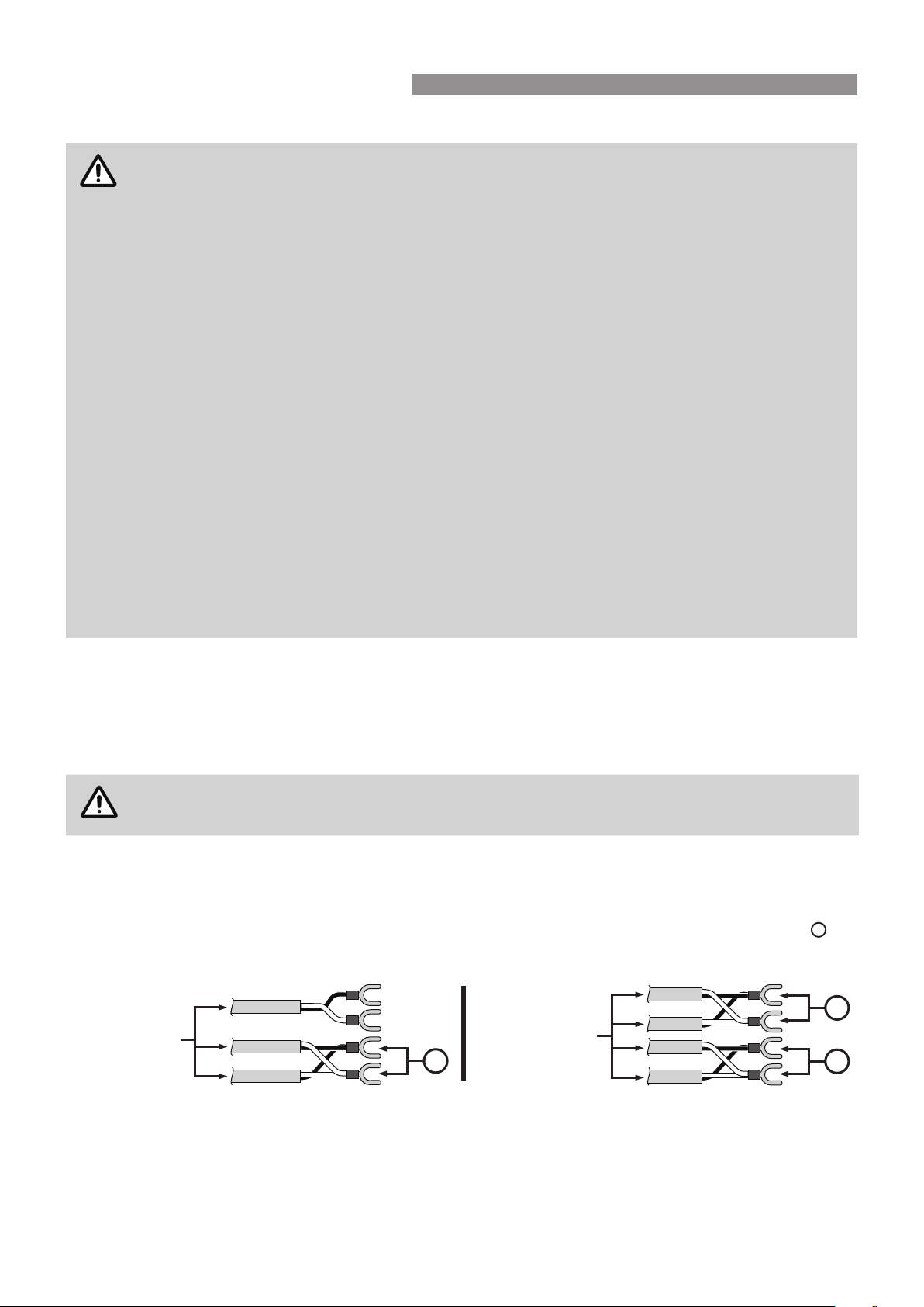
Joining Communication Cables (REU-A / REU-AM)
7KHZDWHUKHDWHUHQGRIWKHFDEOHVDUH¿WWHGZLWKVSDGHWHUPLQDOV2QO\WZRSDLUVRIFDEOHVVSDGHFRQQHFWRUVLQ
WRWDOPD\EHWHUPLQDWHG:KHQDWWDFKLQJWKUHHRUIRXUFDEOHVLWLVQHFHVVDU\WRMRLQWKHFDEOHWHUPLQDOVDVIROORZV
)RUHDFKSDLUFXWRႇWKHH[LVWLQJVSDGHFRQQHFWRUVDQGUHWHUPLQDWHHDFKSDLULQWRDQHZVSDGHFRQQHFWRU
A
so
WKDWWKHUHDUHRQO\WZRVHWVRIVSDGHFRQQHFWRUVVSDGHFRQQHFWRUVLQWRWDOWREHWHUPLQDWHGVSDGHFRQQHFWRUV
are available from your local electrical component retailer).
Follow steps 1 through 5 of "Connecting Communication Cable(s) With 'Ezi connect' (REU-A / REU-AM)" on page
27 to terminate the joined cable pairs to the water heater.
When
Terminating
Three Cables
When
Terminating
Four Cables
A
A
A
WATER CONTROLLER INSTALLATION
Rinnai 27 HW_CF OIM
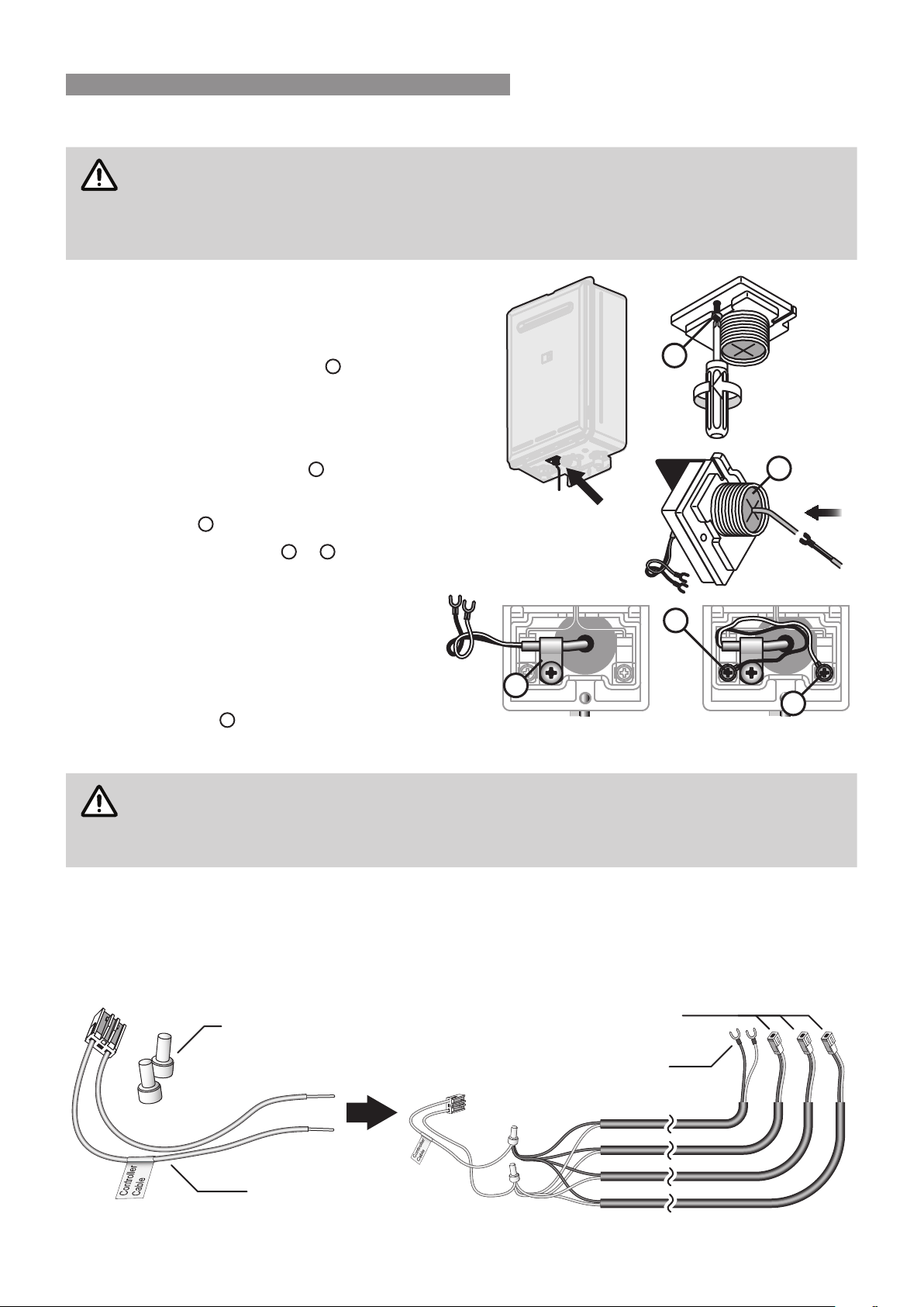
Connecting Communication Cable(s) With 'Ezi connect' (REU-A / REU-AM)
CAUTION
DO NOT attempt to connect cables to the 'Ezi connect' cable connector at the water heater
XQOHVV WKH HOHFWULF SRZHU WR WKH ZDWHU KHDWHU LV VZLWFKHG µRႇ¶ RWKHUZLVH GDPDJH WR HOHFWULFDO
components may occur.
,I \RXU ZDWHU KHDWHU LV QRW ¿WWHG ZLWK DQ (]L FRQQHFW FDEOH FRQQHFWRU LQVWDOODWLRQ PXVW EH
FRPSOHWHGE\DTXDOL¿HGDQGOLFHQVHGWUDGHVSHUVRQ
1. Isolate the electric power supply by switching
WKH SRZHU SRLQW Rႇ DQG UHPRYLQJ WKH SRZHU
plug of the water heater from the electric power
socket.
2. Remove the retaining screw
A
of the 'Ezi
connect' cable connector at the base of the
appliance.
3. Swing the 'Ezi connect' cable connector door
open and thread the cable through the weather
seal of the cable access hole
B
in the direction
VKRZQDOORZLQJVXႈFLHQWFDEOHOHQJWKVRWKDW
the sheath of the cable can be secured with
cable clamp
C
.
Loosen screw terminals
D
&
E
and connect
the cable spade connectors to these terminals
and re-tighten.
Polarity is not important, either wire colour can
be connected to either terminal.
5. Return the 'Ezi connect' cable connector to
the original position taking care not to damage
cable wires in the process and replace the
retaining screw
A
.
Connecting Communication Cables to Mini-Plug (REU-E & REU-VCM)
CAUTION
Installation MUSTEHFRPSOHWHGE\DTXDOL¿HGDQGOLFHQVHGWUDGHVSHUVRQ
DO NOT attempt to connect water controller cables to the mini-plug when it is plugged into the
3&%XQOHVVWKHHOHFWULFSRZHUWRWKHZDWHUKHDWHULVVZLWFKHGµRႇ¶RWKHUZLVHGDPDJHWRHOHFWULFDO
components may occur.
Water controllers are connected to the PCB via a dedicated pre-wired mini-plug (supplied).
Use the supplied electrical cable connectors to terminate the water controller wires to those of the mini-plug. The
existing spade connectors of the communication cables will need to be removed prior to termination. Controllers
are not polarity sensitive, however to avoid confusion it is recommended that like coloured wires be terminated
together.
A
C
E
D
B
Electrical Connectors
(Supplied with Water Controllers)
Communications Cable
MC-100V, MC-503RC-M
Pre-wired Mini-Plug
(Supplied)
Communications Cable
MC-91Q, MC-601Q, BC-100V
WATER CONTROLLER INSTALLATION
Rinnai 28 HW_CF OIM
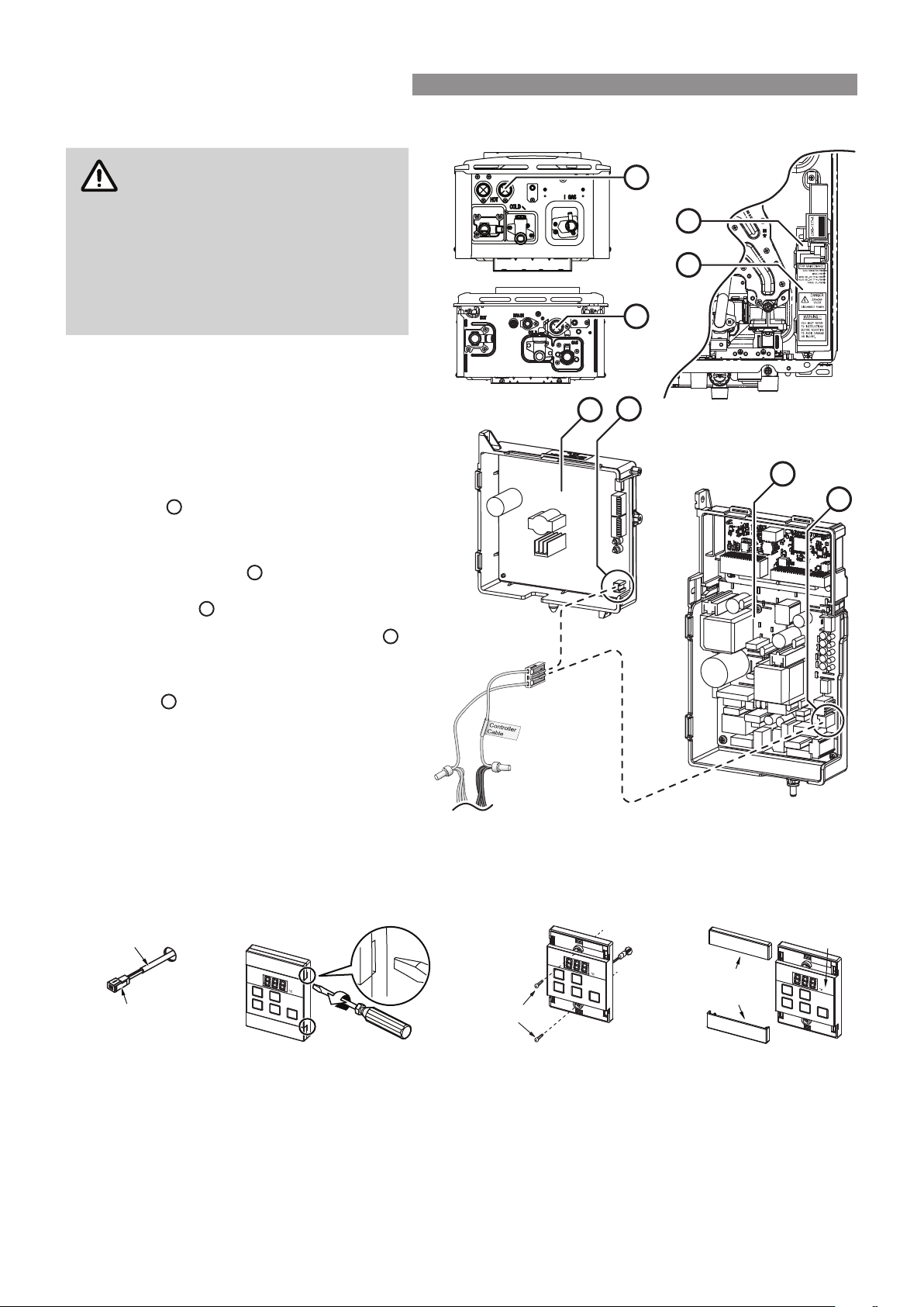
Connecting Communication Cables to PCB (REU-E & REU-VCM)
CAUTION
Installation MUST be completed
E\ D TXDOL¿HG DQG OLFHQVHG WUDGHV
person.
DO NOT attempt to connect mini-
plug or water controller cables
to the water heater unless the
electric power to the water heater is
VZLWFKHGµRႇ¶RWKHUZLVHGDPDJHWR
electrical components may occur.
1. Isolate the electric power supply by
VZLWFKLQJWKHSRZHUSRLQWRႇDQGUHPRYLQJ
the power plug of the water heater from
the electric power socket.
2. Remove the front cover of the appliance.
3. Insert the mini-plug and the connected
water controller cables through the cable
access
A
at the base of the appliance.
Ensuring that the cable connectors are
located inside the appliance for protection.
Locate the PCB
B
, (bottom right of
appliance), and carefully rotate the plastic
safety cover
C
out of the way.
5. Locate the accessory port socket
D
(bottom front of the PCB).
6. Plug the mini-plug into the accessory port
socket
D
(the plug and socket are keyed
so that they can only be plugged in the one
direction).
7. Proceed with the water controller
installation and connect the communication
cables to controllers.
UNIVERSAL WATER CONTROLLER (MC-601Q) INSTALLATION
1. Determine the most suitable position, refer "Location" on page 26.
2. Mark and drill 3 holes (mounting and cable access) refer to page 37 for water controller dimensions.
3. When running cable through the access hole ensure the connector end of the cable is located nearest to the
water controller (Fig. 1).
Carefully remove the cover plates from the water controller, using a screw driver (Fig. 2).
5. Connect the cable to the water controller. Feed any excess cable lengths into the wall cavity to avoid the
pinching of cables between the wall and the water controller.
6. )L[WKHZDWHUFRQWUROOHUWRWKHZDOOXVLQJWKHDSSURSULDWH¿[LQJV)LJ
7. 5HPRYHSURWHFWLYH¿OPIURPWKHZDWHUFRQWUROOHUIDFHDQGUHSODFHWKHFRYHUSODWHV)LJ
D
B
C
B
A
A
REU-VCMREU-E
REU-E PCB
REU-VCM PCB
D
B
REU-E shown, REU-VCM is similar.
Connector
Controller Cable
Screws
Film
Fig. 1 Fig. 2 Fig. 3 Fig. 4
Cover
Plates
WATER CONTROLLER INSTALLATION
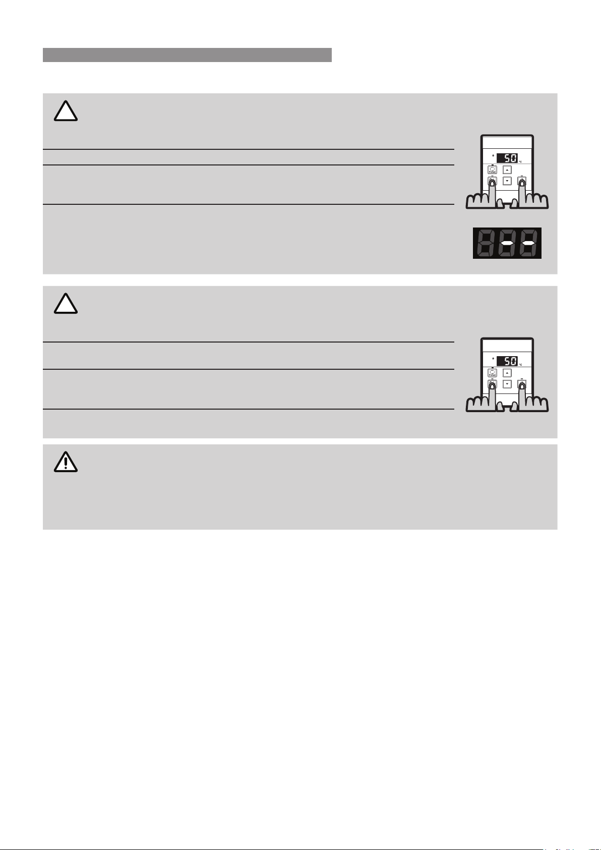
Rinnai 29 HW_CF OIM
Additional Programming & Activation Requirements
Q
UESTION
?
1
Are there four water controllers connected?
IF NO:
You have three (or fewer) water controllers, go to Question 2.
IF YES:
<RXZLOOQHHGWRDFWLYDWHWKHIRXUWKZDWHUFRQWUROOHUDVIROORZV
STEP 1:
)RU WKH ZDWHU FRQWUROOHU LQWKH .,7&+(1 21/<SUHVV DQG KROG WKH µ3ULRULW\
7UDQVIHU¶DQGµ2Q2ႇ¶EXWWRQVVLPXOWDQHRXVO\VHH)LJXQWLODµEHHS¶LVKHDUG
(approximately 5 seconds).
STEP 2:
Check that the display on ALL FOUR water controllers is lit and displaying a
WHPSHUDWXUHZKHQµVZLWFKHGRQ¶,IDQ\21(RIWKHZDWHUFRQWUROOHUGLVSOD\V
two dashes (see Fig. 2) repeat STEP 1.
This completes the activation procedure for the fourth water controller, you
may ignore Question 2.
Q
UESTION
?
2
Is the water heater marked to state it delivers water not exceeding 50°C?
IF YES:
No further action required..
IF NO:
You will need to program the kitchen water controller to enable selection of
temperatures higher than 50°C.
STEP 1:
)RU WKH ZDWHU FRQWUROOHU LQWKH .,7&+(1 21/<SUHVV DQG KROG WKH µ3ULRULW\
7UDQVIHU¶ DQGµ2Q2ႇ¶ EXWWRQVVLPXOWDQHRXVO\ )LJ XQWLOD µEHHS¶ LV KHDUG
(approximately 5 seconds).
STEP 2:
:KHQWKHZDWHUFRQWUROOHU¿WWHGLQWKH.,7&+(1LVVZLWFKHG2QLWVKRXOGEH
possible to select temperatures higher than 50°C. If not, repeat STEP 1.
NOTE
If the water controller in the kitchen is replaced, repeat STEP 1 for the replacement water
controller.
If the water controller in the kitchen is swapped with another water controller (for example, the
ZDWHUFRQWUROOHU¿WWHGLQDEDWKURRPUHSHDWSTEP 1 for the water controller moved from the
kitchen to the bathroom. Then perform STEP 1 for the water controller moved from bathroom
to the kitchen.
Fig. 1
Fig. 2
Fig. 3
WATER CONTROLLER INSTALLATION
Rinnai 30 HW_CF OIM
TESTING
1. %HIRUH¿QDOFRQQHFWLRQRIWKHZDWHUKHDWHUSXUJHJDVKRWZDWHUDQGFROGZDWHUVXSSO\OLQHV'HEULVRUVZDUI
LQHLWKHUWKHJDVRUZDWHUVXSSOLHVPD\FDXVHGDPDJH
2. 7XUQRQJDVDQGFROGZDWHUVXSSOLHV
3. 7HVWIRUZDWHUOHDNVDQGJDVHVFDSHVQHDUWKHXQLW
4. ,VRODWHJDVVXSSO\5HPRYHWHVWSRLQWVFUHZORFDWHGRQWKHJDVLQOHWFRQQHFWLRQDQGDWWDFKSUHVVXUHJDXJH
IMPORTANT
&RQ¿UPWKH FRQWURO ERDUGGLSVZLWFK VHWWLQJVDUHVHW WRWKH FRUUHFW SRVLWLRQVDV UHTXLUHG LH
IDFWRU\GHIDXOWRUZLWKD6LGHZD\V)OXH'LYHUWHU¿WWHGVHH6LGHZD\V)OXH'LYHUWHU$OOPRGHOV
except REU-VCM" on page 21 for details.
5. 7XUQWKHSRZHURQDWWKHSRZHUSRLQWVRFNHWDQGWXUQRQJDV
6. ,IZDWHUFRQWUROOHUVDUH¿WWHGHQVXUHWKH\DUH21ZLWKWKHPD[LPXPGHOLYHU\WHPSHUDWXUHVHOHFWHGDQGRSHQ
ALLDYDLODEOHKRWZDWHURXWOHWV
,IZDWHUFRQWUROOHUVDUHQRW¿WWHGVLPSO\RSHQALL DYDLODEOHKRWZDWHURXWOHWV
CAUTION
Ensure building occupants DO NOT have access to hot water outlets during this procedure.
7. 2SHUDWHALLRWKHUJDVDSSOLDQFHVDWWKHLUPD[LPXPJDVUDWHLQDFFRUGDQFHZLWKPDQXIDFWXUHUVLQVWUXFWLRQV
8. :LWKDOOJDVDSSOLDQFHVLQRSHUDWLRQDWPD[LPXPJDVUDWHWKHSUHVVXUHVKRXOGUHDGEHWZHHQN3D
RQ1DWXUDO*DV2Q/3*WKHSUHVVXUHVKRXOGEHN3D,IWKHSUHVVXUHLVORZHUWKHJDVVXSSO\LV
LQDGHTXDWHDQGWKHDSSOLDQFHZLOOQRWRSHUDWHWRVSHFL¿FDWLRQ,WLVWKH,QVWDOOHUVUHVSRQVLELOLW\WRFKHFNWKH
JDVPHWHUVHUYLFHUHJXODWRUDQGSLSHZRUNIRUFRUUHFWRSHUDWLRQVL]LQJDQGUHFWLI\DVUHTXLUHG
NOTE
The gas regulator on the appliance is electronically controlled and factory pre-set. Under normal
circumstances it DOES NOT need adjustment during installation.
9. &ORVHKRWZDWHUWDSVLQFOXGLQJWKHVKRZHU
10. ,QVSHFWDQGFOHDQWKHVWUDLQHUORFDWHGRQWKHFROGZDWHULQOHWFRQQHFWLRQ7KLVSURFHGXUHPD\QHHGWREH
UHSHDWHGWRHQVXUHWKHVWUDLQHUUHPDLQVFOHDUHVSHFLDOO\RQQHZLQVWDOODWLRQV
11. ,IZDWHUFRQWUROOHUVDUH¿WWHGLWLVQHFHVVDU\WRWHVWWKHLURSHUDWLRQWKURXJKWKHFRPSOHWHUDQJHRIIXQFWLRQV
UHIHUWRWKH2SHUDWLRQVHFWLRQVRIWKLVPDQXDO
12. &RQ¿UP WKH KRW ZDWHU GHOLYHU\ WHPSHUDWXUHV XVLQJ D WKHUPRPHWHU ,I FRQWUROOHUV DUH ¿WWHG HQVXUH
WHPSHUDWXUHVH[FHHGLQJ&FDQQRWEHVHOHFWHGRQEDWKURRPRUHQVXLWHFRQWUROOHUV5HIHUWRWKHVHFWLRQ
µ'HOLYHU\7HPSHUDWXUH¶EHORZIRUPRUHGHWDLOV
13. $IWHUWHVWLQJLVFRPSOHWHGH[SODLQWRWKHKRXVHKROGHUWKHIXQFWLRQVDQGRSHUDWLRQRIWKHZDWHUKHDWHUDQG
ZDWHUFRQWUROOHUVLI¿WWHG(QVXUH WKH ,QVWDOODWLRQ5HFRUGRQSDJH LV ¿OOHGLQDQGWKDWWKLV ERRNOHW LV
KDQGHGWRWKHFXVWRPHU5HPLQGLQJWKHFXVWRPHUWRFRPSOHWHWKH:DUUDQW\&DUGDQGIRUZDUGWR5LQQDL
DELIVERY TEMPERATURE
50°C Compliant Models
& &RPSOLDQW DSSOLDQFHV DUH IDFWRU\ VHW WR GHOLYHU D PD[LPXP WHPSHUDWXUH QRW H[FHHGLQJ & )RU ¿QH
WXQLQJWKH\KDYHDQLQFUHPHQWDODGMXVWPHQWPHFKDQLVPWKDWDOORZVWKHLQVWDOOHUWRLQFUHDVHWKHDSSOLDQFHGHOLYHU\
WHPSHUDWXUHLQFUHPHQWDOO\IURPWKH)DFWRU\6HW¶YDOXHWRWHPSHUDWXUHVVOLJKWO\H[FHHGLQJ&7KLVLVLQWHQGHG
WRHQDEOHFRPSHQVDWLRQIRUWHPSHUDWXUHORVVHVLQWKHSLSHZRUNEHWZHHQWKHZDWHUKHDWHUDQGDQ\RXWOHWVDQG
DFKLHYHWKHUHTXLUHGWHPSHUDWXUHDWWKHRXWOHW,QVWUXFWLRQVIRULQFUHPHQWDOWHPSHUDWXUHDGMXVWPHQWDUHORFDWHGLQ
WKHLQVWUXFWLRQSRFNHWLQVLGHWKHDSSOLDQFHIURQWFRYHU
For All Other Models
5LQQDLJDVFRQWLQXRXVÀRZZDWHUKHDWHUVDUHIDFWRU\SUHVHWWRYDULRXVPD[LPXPGHOLYHU\WHPSHUDWXUHVGHSHQGLQJ
RQ PRGHO DQG WKHLU LQWHQGHG DSSOLFDWLRQ )RU WKH PDMRULW\ RI DSSOLFDWLRQV WKH IDFWRU\ SUHVHW WHPSHUDWXUH LV
DSSURSULDWH,QWKHXQOLNHO\HYHQWLWLVQRWWKLVVHWWLQJFDQEHLQFUHDVHGRUGHFUHDVHGE\WKHLQVWDOOHU,QVWUXFWLRQVIRU
FKDQJLQJWKHPD[LPXPGHOLYHU\WHPSHUDWXUHDUHORFDWHGLQWKHLQVWUXFWLRQSRFNHWLQVLGHWKHDSSOLDQFHIURQWFRYHU
COMMISSIONING

Rinnai 31 HW_CF OIM
GAS PRESSURE SETTING
7KHUHJXODWRULVHOHFWURQLFDOO\FRQWUROOHGDQGIDFWRU\SUHVHW8QGHUQRUPDOFLUFXPVWDQFHVLWDOES NOTUHTXLUH
DGMXVWPHQWGXULQJLQVWDOODWLRQ0DNHDGMXVWPHQWVONLYLIWKHXQLWLVQRWRSHUDWLQJFRUUHFWO\DQGDOORWKHUSRVVLEOH
FDXVHV IRU LQFRUUHFW RSHUDWLRQ KDYH EHHQ HOLPLQDWHG ,QVWUXFWLRQV IRU JDV SUHVVXUH VHWWLQJ DUH ORFDWHG LQ WKH
LQVWUXFWLRQSRFNHWLQVLGHWKHDSSOLDQFHIURQWFRYHU
NOTE
For all injector size and gas pressure values refer to the appliance data plate, located on the left
hand side of the water heater.
WIRING DIAGRAM
7KHZLULQJGLDJUDPLVORFDWHGLQWKHLQVWUXFWLRQSRFNHWLQVLGHWKHDSSOLDQFHIURQWFRYHU
COMMISSIONING CHECK LIST
$ FRPPLVVLRQLQJ FKHFNOLVWLVSURYLGHG RQWKHDSSOLDQFHIURQW FRYHU WRHQDEOHWKHLQVWDOOHU WRVWHSWKURXJKWKH
FRUUHFWFRPPLVVLRQLQJSURFHGXUHZKHQLQVWDOOLQJD5LQQDLJDVFRQWLQXRXVÀRZZDWHUKHDWHU
7KHFKHFNOLVWFDQDOVRDVVLVWWKHLQVWDOOHUWRLGHQWLI\SRWHQWLDOLQVWDOODWLRQHUURUVWKDWPD\SUHYHQWWKHDSSOLDQFH
IURPRSHUDWLQJFRUUHFWO\
INSTALLATION RECORD
7KH,QVWDOODWLRQ5HFRUGLVDUHIHUHQFHIRUWKHHQGXVHUKHOSOLQHVWDႇDQGVHUYLFHWHFKQLFLDQV(QVXULQJWKDWWKLV
LQIRUPDWLRQLVDYDLODEOHKHUHZLOOEHKHOSIXOLQWKHHYHQWWKDWDVHUYLFHHQTXLU\LVUHTXLUHG
Installer Details
,QVWDOODWLRQ&RPSDQ\1DPH
$GGUHVV
7HOHSKRQH0RELOH3KRQH
(PDLO
&HUWL¿FDWHRI&RPSOLDQFH&HUWL¿FDWLRQ1R
$XWKRULVHG3HUVRQV/LFHQFH1R
,QVWDOOHUV1DPH
,QVWDOOHUV6LJQDWXUH
,QVWDOODWLRQ'DWH
System Details
:DWHU+HDWHU0RGHO1XPEHU REU-
:DWHU+HDWHU6HULDO1XPEHU
* This information will need to be copied from the data plate, located on the left hand side of appliance.
,QVWDOODWLRQ$GGUHVV
COMMISSIONING
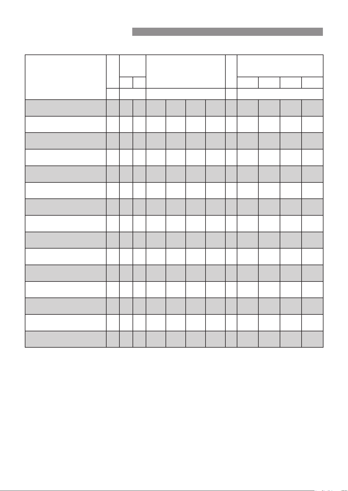
Rinnai 32 HW_CF OIM
TABLE 1. SUPPLY, FLOW RATES, WEIGHTS & SERVICE CONNECTIONS
Model
Gas Rate
Water
Supply
Pressure
Max Flow at Temp Rise
(at minimum water supply pressure)
Weight
Fittings
Min Max Hot Cold Gas Cond.
MJ/hr kPa L/min / °C kg (DN = mm)
REU-AM1220WD -
,Q¿QLW\
92 120 1000 15 / 20 12 / 25 7.5 / 40 6 / 50 13.5 R ½ (15) R ½ (15) R ¾ (20) -
REU-AM1620WD -
,Q¿QLW\
124 120 1000 20 / 20 16 / 25 10 / 40 8 / 50 13.5 R ½ (15) R ½ (15) R ¾ (20) -
REU-AM2024WD -
,Q¿QLW\
156 160 1000 24 / 20 20 / 25 12.5 / 40 10 / 50 14.5 R ¾ (20) R ¾ (20) R ¾ (20) -
REU-AM2626WD -
,Q¿QLW\
199 200 1000 26 / 20 26 / 25 16.3 / 40 13 / 50 15.5 R ¾ (20) R ¾ (20) R ¾ (20) -
REU-AM2626WDL -
,Q¿QLW\7RXFK
199 200 1000 26 / 20 26 / 25 16.3 / 40 13 / 50 15.5 R ¾ (20) R ¾ (20) R ¾ (20) -
REU-AM3237W -
,Q¿QLW\
250 200 1000 40 / 20 32 / 25 20 / 40 16 / 50 23 R ¾ (20) R ¾ (20) R ¾ (20) -
REU-AM3237WC -
HD32e
250 200 1000 40 / 20 32 / 25 20 / 40 16 / 50 23 R ¾ (20) R ¾ (20) R ¾ (20) -
REU-E1620W -
,Q¿QLW\(QYLUR
110 140 1000 20 / 20 16 / 25 10 / 40 8 / 50 16 R ½ (15) R ½ (15) R ¾ (20) R ½ (15)
REU-E2626W -
,Q¿QLW\(QYLUR
175 220 1000 26 / 20 26 / 25 16.3 / 40 13 / 50 18 R ¾ (20) R ¾ (20) R ¾ (20) R ½ (15)
REU-VCM2837FF -
,Q¿QLW\L
210 220 1000 35 / 20 28 / 25 17.5 / 40 14 / 50 21 R ¾ (20) R ¾ (20) R ¾ (20) -
REU-VCM2837FFC -
HD28i
210 220 1000 35 / 20 28 / 25 17.5 / 40 14 / 50 21 R ¾ (20) R ¾ (20) R ¾ (20) -
REU-VCM2837WC -
HD28e
210 220 1000 35 / 20 28 / 25 17.5 / 40 14 / 50 20 R ¾ (20) R ¾ (20) R ¾ (20) -
REU-A1620WB -
B16
124 120 1000 20 / 20 16 / 25 10 / 40 8 / 50 13 R ½ (15) R ½ (15) R ¾ (20) -
REU-A2024WB -
B20
156 160 1000 24 / 20 20 / 25 12.5 / 40 10 / 50 14 R ¾ (20) R ¾ (20) R ¾ (20) -
REU-A2626WB -
B26
199 200 1000 26 / 20 26 / 25 16.3 / 40 13 / 50 15 R ¾ (20) R ¾ (20) R ¾ (20) -
SPECIFICATIONS
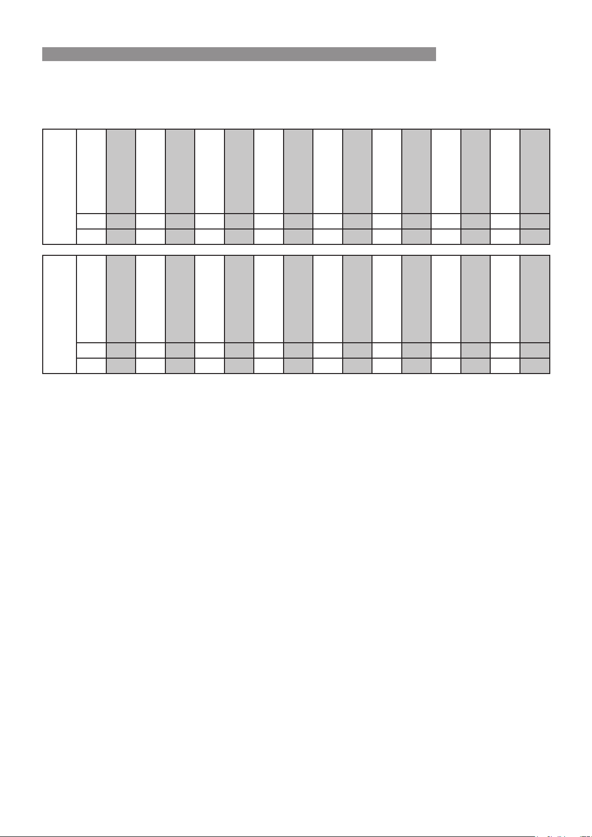
Rinnai 33 HW_CF OIM
TABLE 2. MAXIMUM DELIVERY TEMPERATURES
(a) Factory "Pre-Set" Maximum delivery temperature (°C)
(b) Can the Factory "Pre-Set" Maximum delivery temperature be changed by an authorised person?
Non - 50°C
Compliant - Models
'HOLYHU\7HPSHUDWXUH
REU-AM1220WD
REU-AM1620WD
REU-AM2024WD
REU-AM2626WD
REU-AM2626WDL
REU-AM3237W
REU-AM3237WC
REU-E1620W
REU-E2626W
REU-VCM2837FF
REU-VCM2837FFC
REU-VCM2837WC
REU-A1620WB
REU-A2024WB
REU-A2626WB
(a)606060606060606060607575606060
(b) Yes Yes Yes Yes Yes Yes Yes Yes Yes Yes Yes Yes Yes Yes Yes
50°C Compliant - Models
'HOLYHU\7HPSHUDWXUH
REU-AM1220WD-50
REU-AM1620WD-50
REU-AM2024WD-50
REU-AM2626WD-50
REU-AM2626WDL-50
REU-AM3237W-50
REU-AM3237WC-50
REU-E1620W-50
REU-E2626W-50
REU-VCM2837FF-50
REU-VCM2837FFC-50
REU-VCM2837WC-50
REU-A1620WB-50
REU-A2024WB-50
REU-A2626WB-50
(a)505050505050505050505050505050
(b)NoNoNoNoNoNoNoNoNoNoNoNoNoNoNo
SPECIFICATIONS
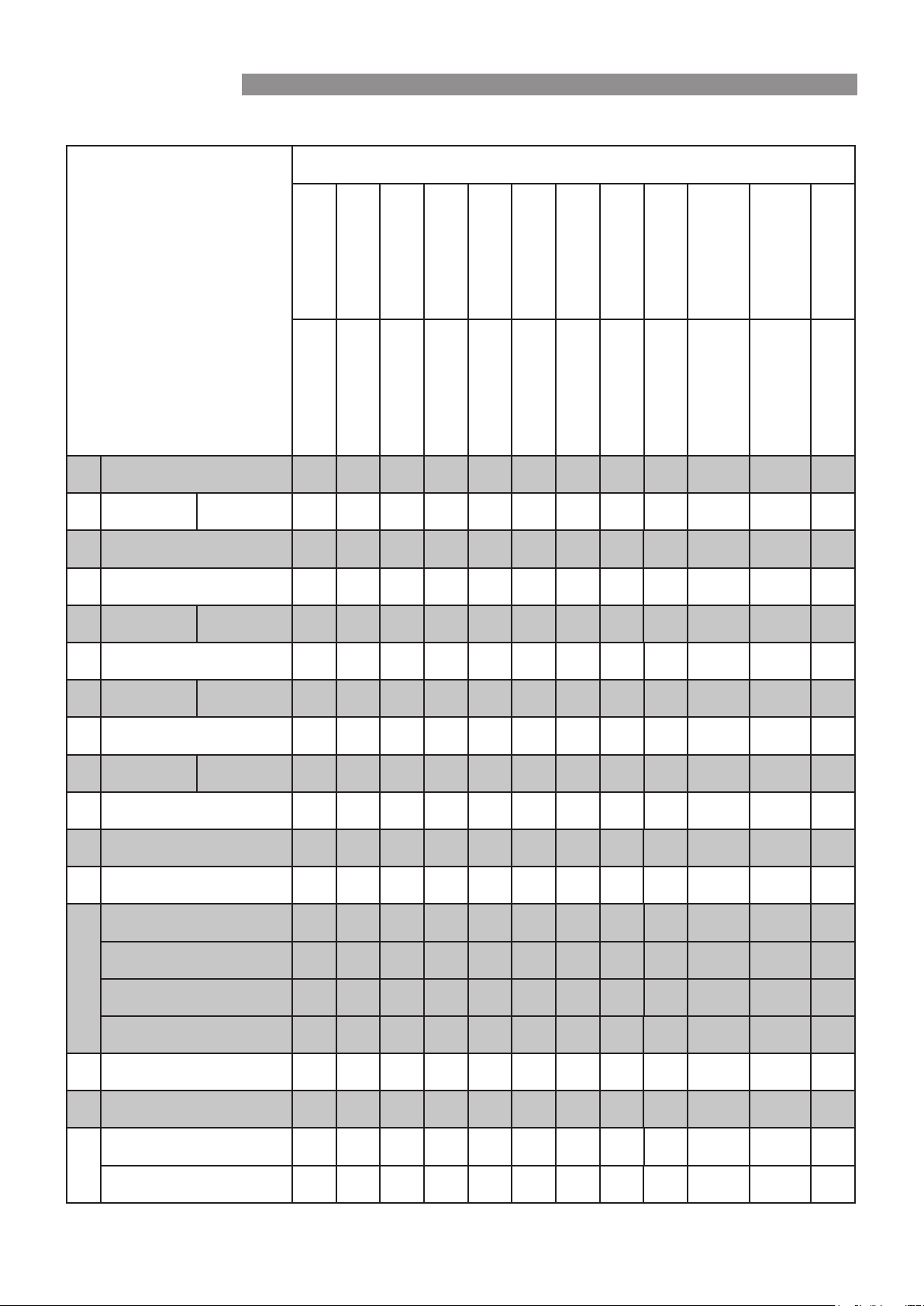
Rinnai 34 HW_CF OIM
TABLE 3. APPLIANCE DIMENSIONS - INFINITY, ENVIRO, INFINITY-i & HD
All dimensions in mm
unless otherwise stated.
Model
,Q¿QLW\
,Q¿QLW\
,Q¿QLW\
,Q¿QLW\
,Q¿QLW\7RXFK
,Q¿QLW\
HD32e
,Q¿QLW\(QYLUR
,Q¿QLW\(QYLUR
,Q¿QLW\L
HD28i
HD28e
REU-AM1220WD
REU-AM1620WD
REU-AM2024WD
REU-AM2626WD
REU-AM2626WDL
REU-AM3237W
REU-AM3237WC
REU-E1620W
REU-E2626W
REU-VCM2837FF
REU-VCM2837FFC
REU-VCM2837WC
A Width 356 356 356 356 356 470 470 351 351 357 357 357
B Depth Min / Max 202 202 202 202 202 271 271 220 220 245 / 278 245 / 278 272
C Height Unit 503 503 503 503 503 600 600 531 531 583 583 583
D +HLJKWLQFOXGLQJEUDFNHWV 571 571 571 571 571 640 640 565 565 648 648 646
E
Hot water outlet
(from wall)
Min / Max 87 87 87 87 87 115 115 103 103 91 / 124 91 / 124 96
F +RWZDWHURXWOHWIURPFHQWUH 105 105 105 105 105 61 61 127 127 110 110 110
G
Cold water inlet
(from wall)
Min / Max 68 68 68 68 68 125 125 63 63 70 / 103 70 / 103 75
H &ROGZDWHULQOHWIURPFHQWUH 10 10 10 10 10 67 67 20 20 27* 27* 27*
I
*DVFRQQHFWLRQ
(from wall)
Min / Max 77 77 77 77 77 61 61 61 61 99 / 132 99 / 132 104
J *DVFRQQHFWLRQIURPFHQWUH 83 83 83 83 83 120 120 83 83 89 89 89
K Neutraliser outlet (from wall) -------137137- - -
L 1HXWUDOLVHURXWOHWIURPFHQWUH -------7*7* - - -
M
*DVFRQQHFWLRQOHQJWKIURP
base)
40 40 40 40 40 37 37 38 38 36 36 36
&ROGFRQQHFWLRQOHQJWKIURP
base)
50 50 50 50 50 49 49 50 50 46 46 46
+RWFRQQHFWLRQOHQJWKIURPEDVH 39 39 41 41 41 40 40 39 41 36 36 36
Condensate outlet (from base) - - - - - - - 36 36 - - -
N
Flue spigot height - Internal
models
--------- 68 68 -
O 9HUWLFDOPRXQWLQJKROHFHQWUHV --------- - - -
P
&DEOHDFFHVVKROHVL]H --------- - - -
Position --------- - - -
0HDVXUHPHQWLVIURPWKHOHIWRIWKHFHQWUHOLQH
SPECIFICATIONS
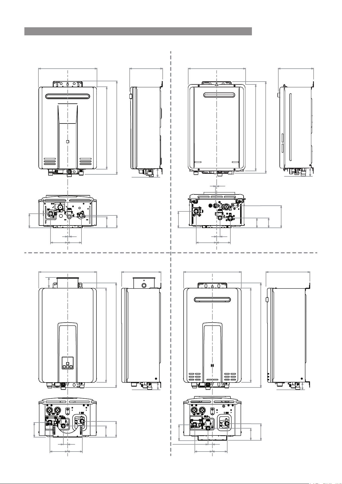
Rinnai 35 HW_CF OIM
M
M
B
B
M
B
DC
A
E
HD-e Series (External)
DC
A
E
F
J
H
I
G
Infinity Series Infinity Enviro Series
DC
A
E
F
J
H
I
G
L
K
B
M
DC
A
E
F J
H
IG
F J
H
IG
Infinty-i / HD-i Series (Internal)
N
SPECIFICATIONS
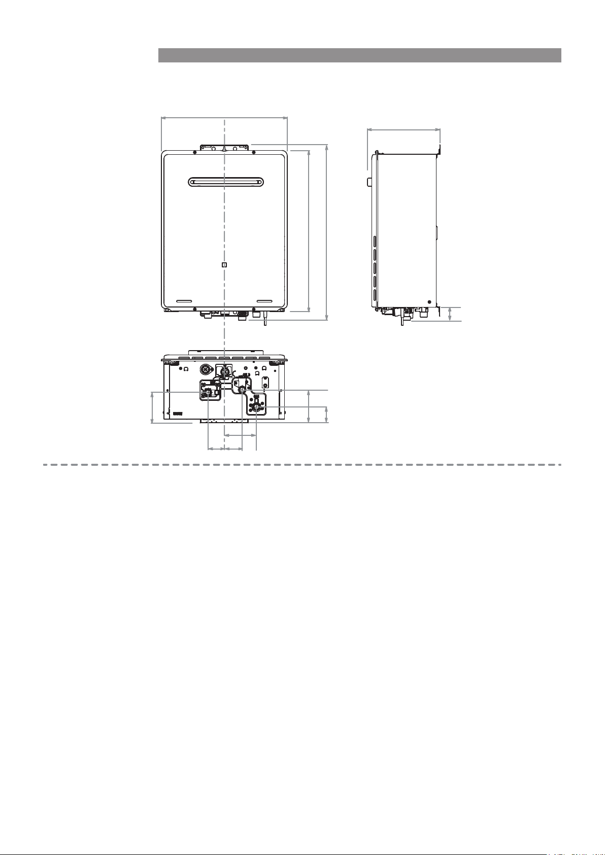
Rinnai 36 HW_CF OIM
Infinity 32 / HD32e Series
A
B
E
DC
F
J
H
I
G
M
SPECIFICATIONS
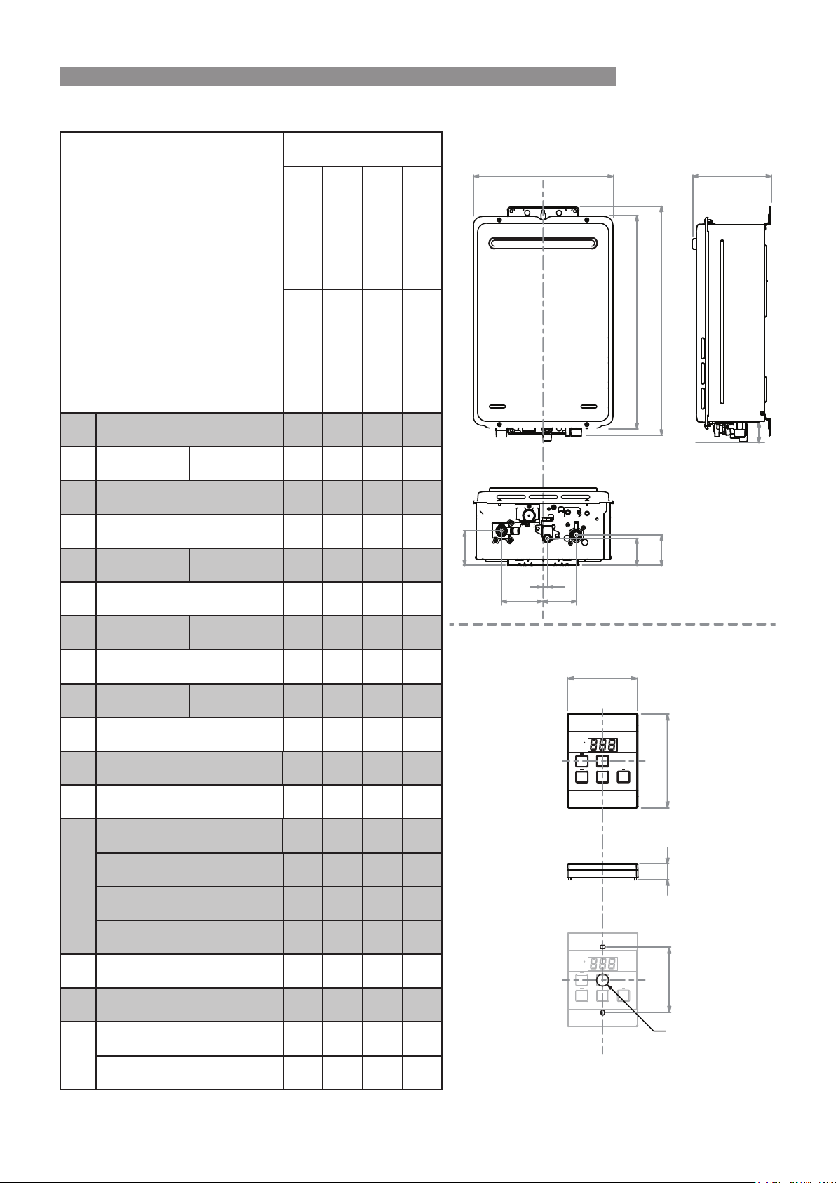
Rinnai 37 HW_CF OIM
TABLE 4. APPLIANCE DIMENSIONS - B SERIES & UNIVERSAL WATER CONTROLLER
All dimensions in mm
unless otherwise stated.
Model
B16
B20
B26
8QLYHUVDO
REU-A1620WB
REU-A2024WB
REU-A2626WB
MC-601Q
A Width 351 351 351 90
B Depth Min / Max 195 195 195 21
C Height Unit 531 531 531 120
D +HLJKWLQFOXGLQJEUDFNHWV 571 571 571 -
E
Hot water outlet
(from wall)
Min / Max 87 87 87 -
F +RWZDWHURXWOHWIURPFHQWUH 105 105 105 -
G
Cold water inlet
(from wall)
Min / Max 68 68 68 -
H &ROGZDWHULQOHWIURPFHQWUH 10 10 10 -
I
*DVFRQQHFWLRQ
(from wall)
Min / Max 77 77 77 -
J *DVFRQQHFWLRQIURPFHQWUH 83 83 83 -
K Neutraliser outlet (from wall) ----
L 1HXWUDOLVHURXWOHWIURPFHQWUH ----
M
*DVFRQQHFWLRQOHQJWKIURPEDVH 40 40 40 -
&ROGFRQQHFWLRQOHQJWKIURPEDVH 50 50 50 -
+RWFRQQHFWLRQOHQJWKIURPEDVH 39 41 41 -
Condensate outlet (from base) ----
N Flue spigot height - Internal models ----
O 9HUWLFDOPRXQWLQJKROHFHQWUHV ---84
P
&DEOHDFFHVVKROHVL]H ---Ø20
Position - - -
Centre
0HDVXUHPHQWLVIURPWKHOHIWRIWKHFHQWUHOLQH
M
B
DC
A
E
F
J
H
I
G
Universal Water Controller - MC-601Q
A
B
C
Drawings are not to scale
P
O
B Series
SPECIFICATIONS
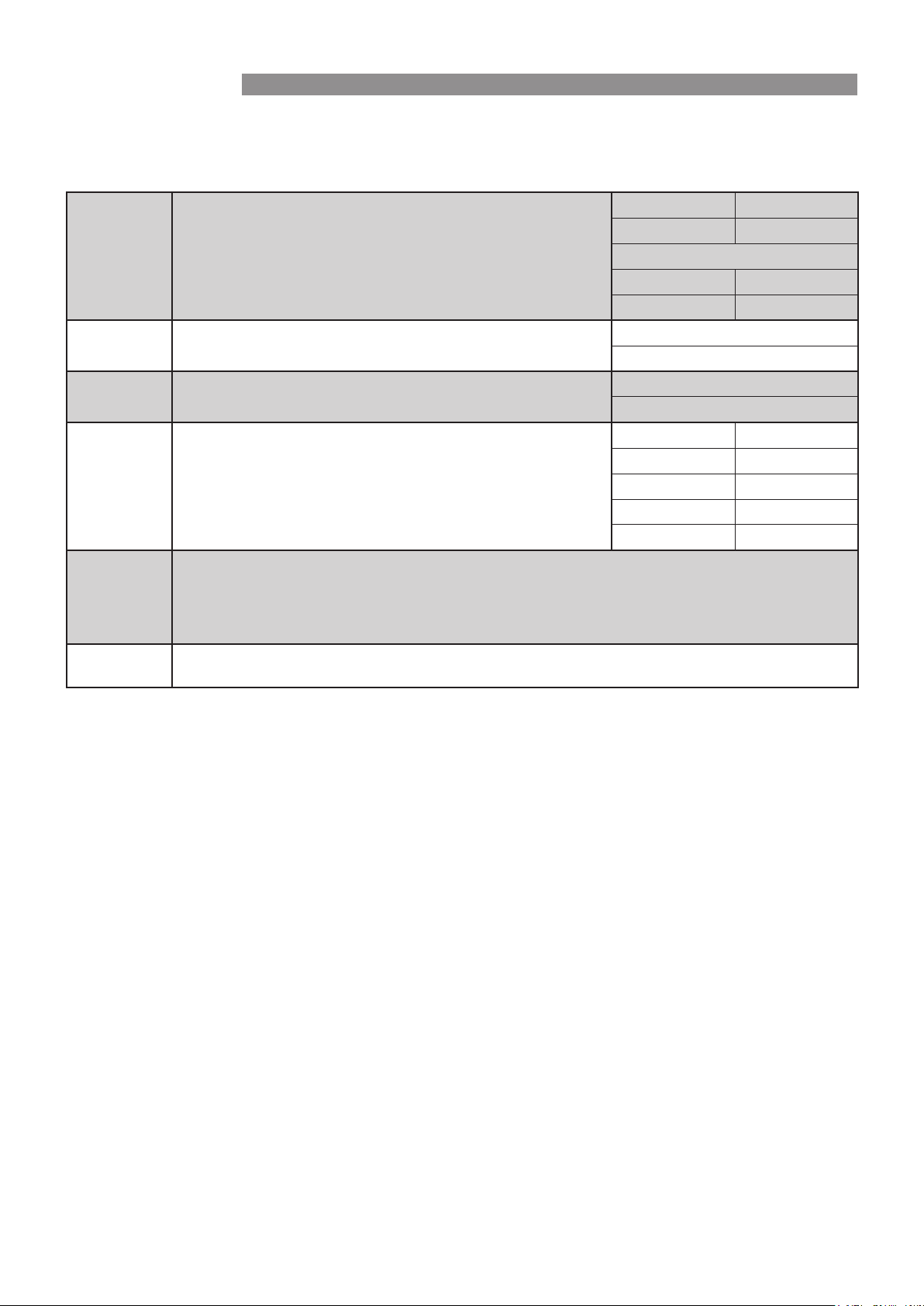
Rinnai 38 HW_CF OIM
TABLE 5. OTHER ACCESSORIES
:KHUH WKH DFFHVVRU\ FRPSDWLELOLW\ LQIRUPDWLRQ LVQRW VSHFL¿HG SOHDVH FRQWDFW 5LQQDL IRU GHWDLOV DERXW RXU IXOO
DFFHVVRU\UDQJHDQGWKHLUPRGHOVXLWDELOLW\RUYLVLWwww.rinnai.com.au.
Pipe
Cover
3LSHFRYHUVDWWDFKHDVLO\WRD5LQQDLJDVFRQWLQXRXVÀRZZDWHU
heater and are designed to conceal pipes and valves.
Pipe covers may also be joined to one another to conceal longer
SLSHZRUN
REU Series Pipe Cover
REU-AM PCD01
Not Available REU-AM3237W/WC
REU-E PCD08
REU-A PC11D
Security
Cage
3URWHFWVWKH5LQQDLJDVFRQWLQXRXVÀRZZDWHUKHDWHUIURPWKHIW
and damage.
All Models
CAGE01
Security
%UDFNHW
3UHYHQWWKHIWRI\RXU5LQQDLJDVFRQWLQXRXVÀRZZDWHUKHDWHUE\
VHFXULQJLWZLWKWKHFXVWRPVHFXULW\EUDFNHW
All Models
SECBKT
6LGHZD\V
Flue
Diverter
'HVLJQHGWRUHGLUHFWÀXHSURGXFWVZKHQD5LQQDLJDVFRQWLQXRXV
ÀRZZDWHUKHDWHULVLQVWDOOHGRQDEDOFRQ\
* SFD-01 = RUE-A2626 / SFD-02 = REU-A1620 / SFD-03 = REU-A2024.
REU Series Diverter
REU-AM SFD-01
REU-AM3237 SFD-05
REU-E SFD-04
REU-A SFD-01/02/03 *
Smart Box
SODVWLF**
Recess Box
(metal) **
5HFHVVER[HVDUHDYDLODEOHLQHLWKHUSODVWLFRUPHWDODQGDUHGHVLJQHGWRSHUPLWDUHFHVVHGLQVWDOODWLRQ
RID5LQQDLJDVFRQWLQXRXVÀRZZDWHUKHDWHULQWRDZDOOFDYLW\VDYLQJSUHFLRXVVSDFH
Recess boxes are also suitable for painting.
** 1RW$YDLODEOH5(8(:5(8(:5(89&0:&))&))DQG5(8$0::&
Water
Controllers
$Q H[WHQGHG UDQJH RI 'HOX[H .LWFKHQ 'HOX[H %DWKURRP DQG :LUHOHVV ZDWHU FRQWUROOHUV DUH DOVR
available.
SPECIFICATIONS

Rinnai 39 HW_CF OIM
NOTES

40 HW_CF_A_AM_E_VCM OIM Issue 5 - August 2022
U340-1330X04(00)
REUA/E/VCM(AU)
Rinnai Australia Pty Ltd
ABN 74 005 138 769 | AU45204
100 Atlantic Drive, Keysborough, Victoria 3173
P.O. Box 460, Braeside, Victoria 3195
Tel: (03) 9271 6625
Fax: (03) 9271 6622
National Help Line
Tel: 1300 555 545* Fax: 1300 555 655
Monday to Friday, 8.00 am to 5.00 pm EST.
After Hours Hot Water Service Line
Tel: 1800 000 340*
*Cost of a local call may be higher from a mobile phone.
(National calls from public phones in Australia are free.)
For further information visit www.rinnai.com.au
or email [email protected]
Rinnai has a Service and Spare Parts network with
personnel who are fully trained and equipped to give
the best service on your Rinnai appliance. If your
appliance requires service, please call our National
Help Line. innai recommends that commercial
appliances be serviced every 1 year and that
domestic appliances be serviced every 2 years.
With our policy of continuous improvement, we
reserve the right to change, or discontinue at any time,
specifications or designs without notice.
U340-1330X04(00)
REU-A/E/VCM(AU)
HW_CF_A_AM_E_VCM OIM Issue 5 - August 2022