
Operator's Manual
®
MIDI LATHE
Model No.
351.217520
CAUTION:
Read and follow all Safety
Rules and Operating
Instructions before First
Use of this Product. Keep
this manual with tool.
Sears, Roebuck and Co., Hoffman Estates, IL 60179 U.S.A.
www.sears.com/craftsman
30897.00 Draft (05/21/09)
Warranty ......................................... 2
Safety Rules .................................... 2-3
Unpacking ...................................... 3-4
Assembly ...................................... 4-5
Installation ...................................... 5-6
Operation ..................................... 6-16
Maintenance .................................... 16
Troubleshooting .................................. 17
Parts Illustration and List ........................ 18-19
Espa_ol ...................................... 20-39
ONE-YEAR FULL WARRANTY ON CRAFTSMAN TOOL
If this Craftsman tool fails due to a defect in material or work-
manship within one year from the date of purchase, call 1-800-
4-MY-HOME®TO ARRANGE FOR FREE REPAIR (or replace-
ment if repair proves impossible).
If this tool is ever used for commercial or rental purposes, this
warranty will apply for only 90 days from the date of purchase.
This warranty gives you specific legal rights and you may
also have other rights which vary from state to state.
Sears, Roebuck and Co., Hoffman Estates, IL 60179
CAUTION: Always follow proper operating procedures as
defined in this manual -- even if you are familiar with use of
this or similar tools. Remember that being careless for even
a fraction of a second can result in severe personal injury.
WARNING: For your own safety, read all of the rules and
precautions before operating tool.
PROPOSITION 65 WARNING: Some dust created
by power sanding, sawing, grinding, drilling and other con-
struction activities contains chemicals known to the state of
California to cause cancer, birth defects or other reproductive
harm.
Some examples of these chemicals are:
• Lead from lead-based paints.
• Crystalline silica from bricks and cement and other
masonry products.
• Arsenic and chromium from chemically-treated lumber.
Your risk from these exposures vary, depending on how often
you do this type of work. To reduce your exposure to these
chemicals: work in a well ventilated area and work with
approved safety equipment. Always wear OSHA/NIOSH
approved, properly fitting face mask or respirator when
using such tools.
BE PREPARED FOR JOB
• Wear proper apparel. Do not wear loose clothing, gloves,
neckties, rings, bracelets or other jewelry which may get
caught in moving parts of machine.
• Wear protective hair covering to contain long hair.
• Wear safety shoes with non-slip soles.
• Wear safety glasses complying with United States ANSI
Z87.1. Everyday glasses have only impact resistant lenses.
They are NOT safety glasses.
• Wear face mask or dust mask if operation is dusty.
• Be alert and think clearly. Never operate power tools when
tired, intoxicated or when taking medications that cause
drowsiness.
PREPARE WORK AREA FOR JOB
• Keep work area clean. Cluttered work areas invite accidents.
• Do not use power tools in dangerous environments. Do not
use power tools in damp or wet locations. Do not expose
power tools to rain.
• Work area should be properly lighted.
• Keep visitors at a safe distance from work area.
• Keep children out of workplace. Make workshop childproof.
Use padlocks, master switches or remove switch keys to
prevent any unintentional use of power tools.
• Keep power cords from coming in contact with sharp
objects, oil, grease, and hot surfaces.
TOOL SHOULD BE MAINTAINED
• Always unplug tool prior to inspection.
• Consult manual for specific maintaining and adjusting
procedures.
• Keep tool lubricated and clean for safest operation.
• Keep all parts in working order. Check to determine that
the guard or other parts will operate properly and perform
their intended function.
• Check for damaged parts. Check for alignment of moving
parts, binding, breakage, mounting and any other condition
that may affect a tool's operation.
• A guard or other part that is damaged should be properly
repaired or replaced. Do not perform makeshift repairs.
(Use parts list provided to order replacement parts.)
• Never adjust attachments while running. Disconnect power
to avoid accidental start-up.
• Have damaged or worn power cords replaced immediately.
• Keep cutting tools sharp for efficient and safest operation.
KNOW HOW TO USE TOOL
• Use right tool for job. Do not force tool or attachment to
do a job for which it was not designed.
• Disconnect tool when changing attachments.
• Avoid accidental start-up. Make sure that the tool is in the
"off" position before plugging in, turning on safety discon-
nect or activating breakers.
• Do not force tool. It will work most efficiently at the rate for
which it was designed.
• Keep hands away from chuck, centers and other moving parts.
• Never leave tool running unattended. Turn the power off
and do not leave tool until it comes to a complete stop.
• Do not overreach. Keep proper footing and balance.
• Never stand on tool. Serious injury could occur if tool is
tipped or if centers are unintentionally contacted.
• Know your tool. Learn the tool's operation, application
and specific limitations.
• Handle workpiece correctly. Mount firmly in holding
devices. Protect hands from possible injury.
• Turn machine off if workpiece splits or becomes loose.
• Use cutting tools as recommended in "Operation."
© Sears, Roebuck and Co,
2
WARNING: For your own safety, do not operate your wood
lathe until it is completely assembled and installed according
to instructions.
PROTECTION: EYES, HANDS, FACE, BODY, EARS
• If any part of your lathe is missing, malfunctioning, or has
been damaged or broken, cease operating immediately
until the particular part is properly repaired or replaced.
• Wear ear plugs or muffs during extended periods of operation.
• Small loose pieces of wood or other objects that contact a
spinning workpiece can be propelled at very high speed.
This can be avoided by keeping the lathe clean.
• Never turn the lathe ON before clearing the bed, head and
tailstock of all tools, wood scraps, etc., except the workpiece
and related support devices for the operation planned.
• Never place your face or body in line with the chuck or
faceplate.
• Never place your fingers or hands in path of cutting tools.
• Never reach in back of the workpiece with either hand to
support the piece, remove wood scraps, or for any other
reason. Avoid awkward operations and hand positions
where a sudden slip could cause fingers or hand to
move into a spinning workpiece.
• Shut the lathe OFF and disconnect power source when
removing the faceplate, changing the center, adding or
removing an auxiliary device, or making adjustments.
• Turn key lock switch to "off" and remove key when tool
is not in use.
• If the workpiece splits or is damaged in any way, turn lathe
OFF and remove the workpiece from the holders. Discard
damaged workpiece and start with a new piece of wood.
• Use extra care when turning wood with twisted grain or
wood that is twisted or bowed i it may cut unevenly or
wobble excessively.
KNOW YOUR CUTTING TOOLS
• Dull, gummy, improperly sharpened or set cutting tools
can cause vibration and chatter during cutting operations.
Minimize potential injury by proper care of tools and
regular machine maintenance.
THINK SAFETY
Safety is a combination of operator common sense and
alertness at all times when the lathe is being used.
• For your own safety, read all rules and precautions in
the operator's manual before using this tool.
• Tighten all clamps, fixtures and tailstock before applying
power. Check to make sure that all tools and wrenches
have been removed.
• With switch off, rotate workpiece by hand to make sure
that there is adequate clearance. Start the machine on
lowest speed setting to verify that the workpiece is secure.
• For large pieces, create a rough shape on another piece
of equipment before installing on faceplate.
• Do not mount any workpieces that have splits or knots.
• Never attempt to remount a faceplate turning to the face-
plate for any reason.
• Never attempt to remount a between-centers turning if the
original centers on the turning have been altered or removed.
• When remounting a between-centers turning that has non-
altered original centers, make sure that the speed is at
the lowest setting for start-up.
• Use extra caution when mounting a between-centers turn-
ing to the faceplate, or a faceplate turning to between-cen-
ters, for secondary operations. Make sure that the speed
is at the lowest setting for start-up.
• Never perform any operation with this lathe where the
workpiece is hand-held. Do not mount a reamer, milling
cutter, drill bit, wire wheel or buffing wheel to the head-
stock spindle.
• When hand-sanding faceplate or between-centers mount-
ed workpieces, complete all sanding BEFORE removing
the workpiece from the lathe.
• Never run the spindle in the wrong direction. The cutting
tool could be pulled from your hands. The workpiece
should always turn towards the operator.
• For spindle turning, ALWAYS position the tool rest above the
centerline of the workpiece and spindle (approximately 1/8").
• Use any drill chuck accessory in the tailstock only. Do
not mount any drill bit that extends more than 6" beyond
chuck jaws.
CAUTION: Follow safety instructions that appear on the
headstock assembly for your lathe.
Refer to Figure 1, page 4.
Check for shipping damage or missing parts. If any parts are
damaged or missing, call 1-800-266-9079 for replacement.
Your wood lathe is shipped complete in one carton and includes
a motor. Separate all parts from packing materials and check
each one with the unpacking list to make certain all items are
accounted for before discarding any packing material.
If any parts are missing, do not attempt to assemble the
lathe, plug in the power cord, or turn the switch on until
the missing parts are obtained and properly installed.
A Lathe Assembly with Tailstock
B Faceplate
C Tool Rest Base
D Tool Rest
E Tool Holder
F Index Pin Assembly
G Live Center
H Center Removal Rod
I Point Removal Tool
J Wrench
K Spur Center
Not Shown:
M6 x 16 Pan Head Screw (2)
M6 Flat Washer (2)
IMPORTANT: The bed is coated with a protectant. To ensure
proper fit and operation, remove coating. Coating is easily
removed with mild solvents, such as mineral spirits, and a
soft cloth. Avoid getting cleaning solution on paint or any of
the rubber or plastic parts. Solvents may deteriorate these
finishes. Use soap and water on paint, plastic or rubber
components. Wipe all parts thoroughly with a clean dry
cloth. Apply paste wax to the bed.
3
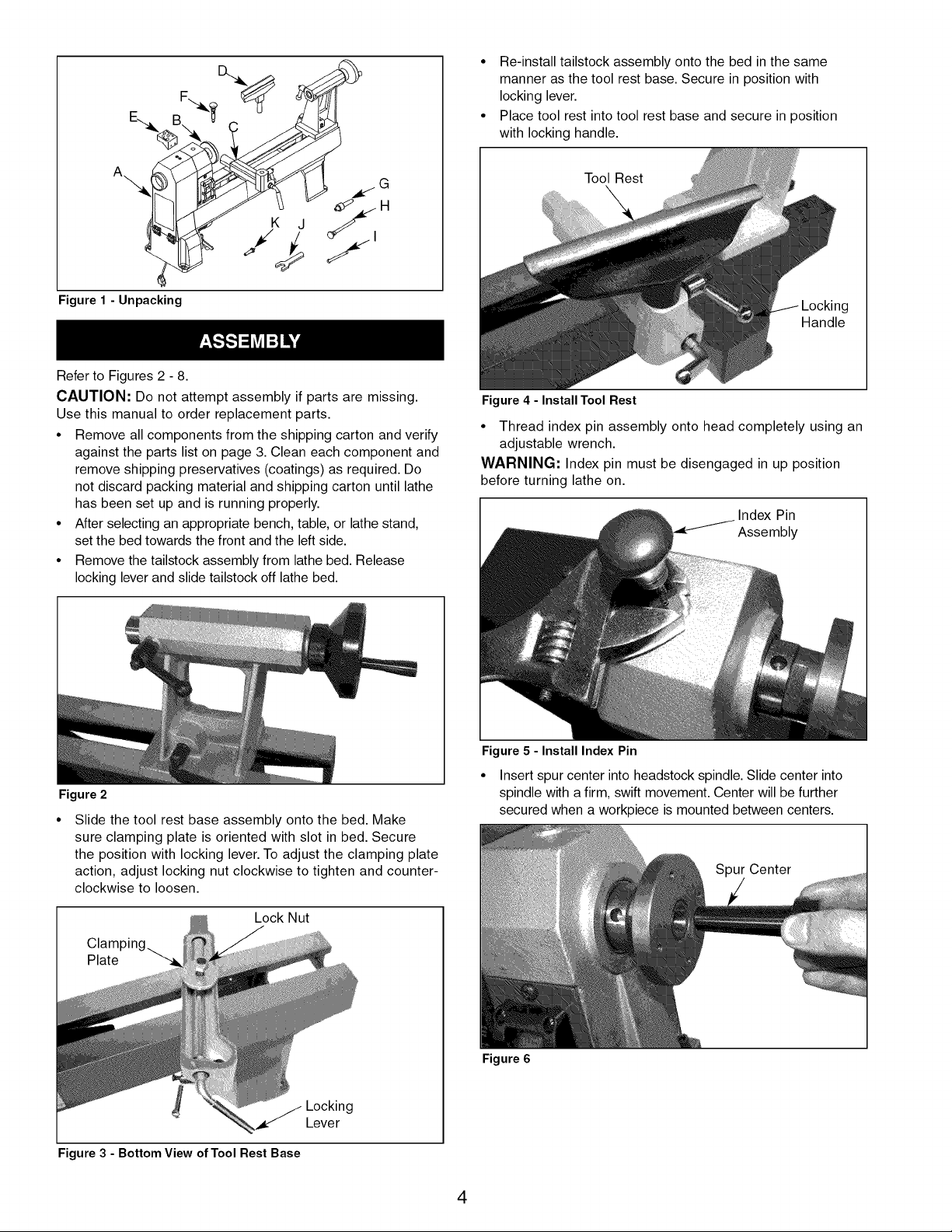
Figure 1 - Unpacking
• Re-install tailstock assembly onto the bed in the same
manner as the tool rest base. Secure in position with
locking lever.
• Place tool rest into tool rest base and secure in position
with locking handle.
Tool Rest
ig
Handle
Refer to Figures 2 - 8.
CAUTION: Do not attempt assembly if parts are missing.
Use this manual to order replacement parts.
• Remove all components from the shipping carton and verify
against the parts list on page 3. Clean each component and
remove shipping preservatives (coatings) as required. Do
not discard packing material and shipping carton until lathe
has been set up and is running properly.
• After selecting an appropriate bench, table, or lathe stand,
set the bed towards the front and the left side.
• Remove the tailstock assembly from lathe bed. Release
locking lever and slide tailstock off lathe bed.
Figure 4 - Install Tool Rest
• Thread index pin assembly onto head completely using an
adjustable wrench.
WARNING: Index pin must be disengaged in up position
before turning lathe on.
I Index Pin
Assembly
Figure 2
Slide the tool rest base assembly onto the bed. Make
sure clamping plate is oriented with slot in bed. Secure
the position with locking lever. To adjust the clamping plate
action, adjust locking nut clockwise to tighten and counter-
clockwise to loosen.
Lock Nut
Figure 3 - Bottom View of Tool Rest Base
Locking
Lever
Figure 5 - Install Index Pin
• Insert spur center into headstock spindle. Slide center into
spindle with a firm, swift movement. Center will be further
secured when a workpiece is mounted between centers.
Spur Center
Figure 6
4
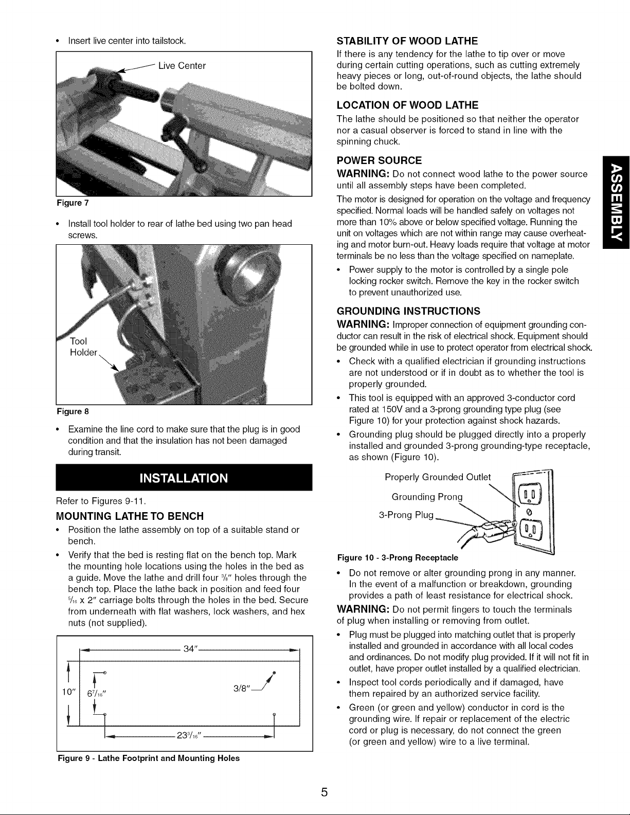
• Insert live center into tailstock.
Live Center
Figure 7
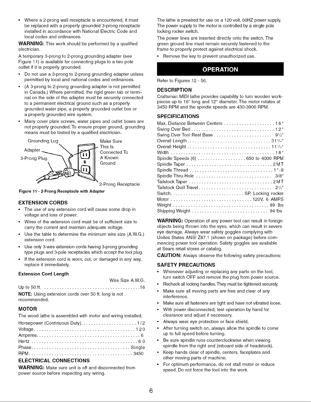
• Install tool holder to rear of lathe bed using two pan head
screws.
Figure 8
• Examine the line cord to make sure that the plug is in good
condition and that the insulation has not been damaged
during transit.
Refer to Figures 9-11.
MOUNTING LATHE TO BENCH
• Position the lathe assembly on top of a suitable stand or
bench.
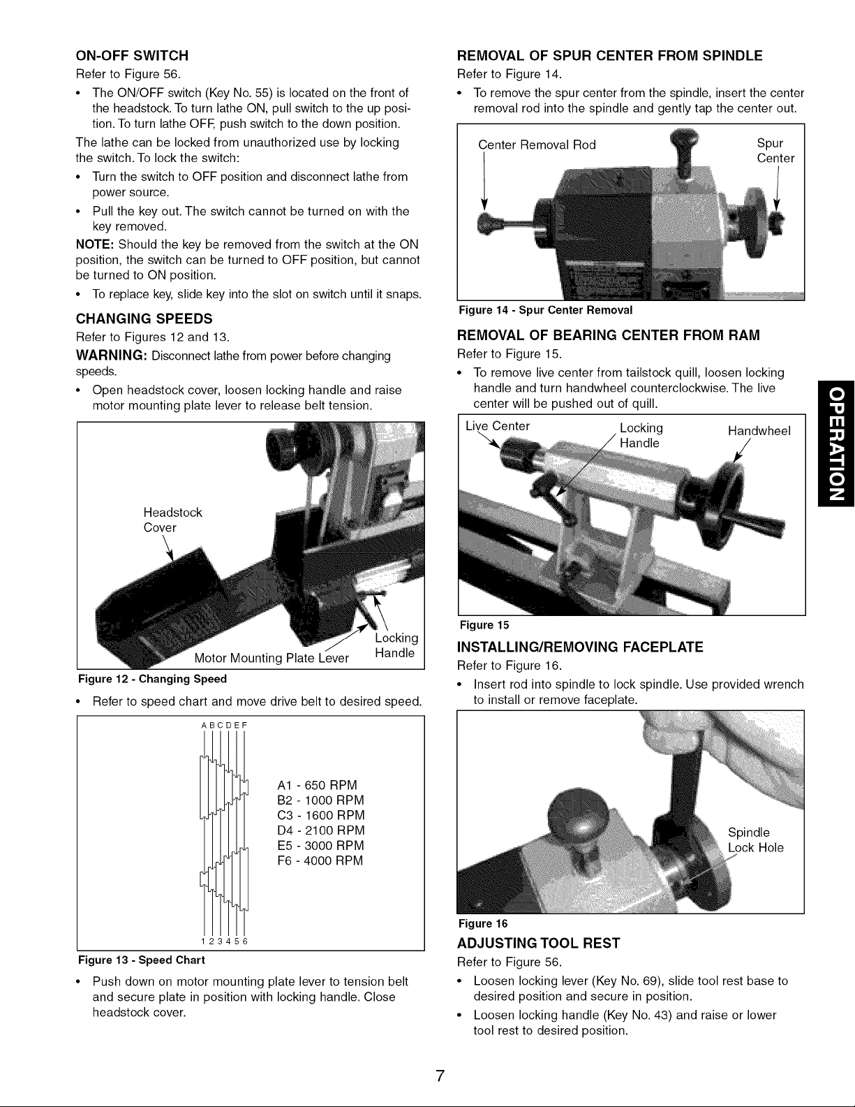
• Verify that the bed is resting flat on the bench top. Mark
the mounting hole locations using the holes in the bed as
a guide. Move the lathe and drill four 3/8"holes through the
bench top. Place the lathe back in position and feed four
8/18x 2" carriage bolts through the holes in the bed. Secure
from underneath with flat washers, lock washers, and hex
nuts (not supplied).
34"
3/8'
10" I 67/1_.
[..,,_ 233/18"
T
,.J
Figure 9 - Lathe Footprint and Mounting Holes
STABILITY OF WOOD LATHE
If there is any tendency for the lathe to tip over or move
during certain cutting operations, such as cutting extremely
heavy pieces or long, out-of-round objects, the lathe should
be bolted down.
LOCATION OF WOOD LATHE
The lathe should be positioned so that neither the operator
nor a casual observer is forced to stand in line with the
spinning chuck.
POWER SOURCE
WARNING: Do not connect wood lathe to the power source
until all assembly steps have been completed.
The motor is designed for operation on the voltage and frequency
specified. Normal loads will be handled safely on voltages not
more than 10% above or below specified voltage. Running the
unit on voltages which are not within range may cause overheat-
ing and motor burn-out. Heavy loads require that voltage at motor
terminals be no less than the voltage specified on nameplate.
• Power supply to the motor is controlled by a single pole
locking rocker switch. Remove the key in the rocker switch
to prevent unauthorized use.
GROUNDING INSTRUCTIONS
WARNING: Improper connection of equipment grounding con-
ductor can result in the risk of electrical shock. Equipment should
be grounded while in use to protect operator from electrical shock.
• Check with a qualified electrician if grounding instructions
are not understood or if in doubt as to whether the tool is
properly grounded.
• This tool is equipped with an approved 3-conductor cord
rated at 150V and a 3-prong grounding type plug (see
Figure 10) for your protection against shock hazards.
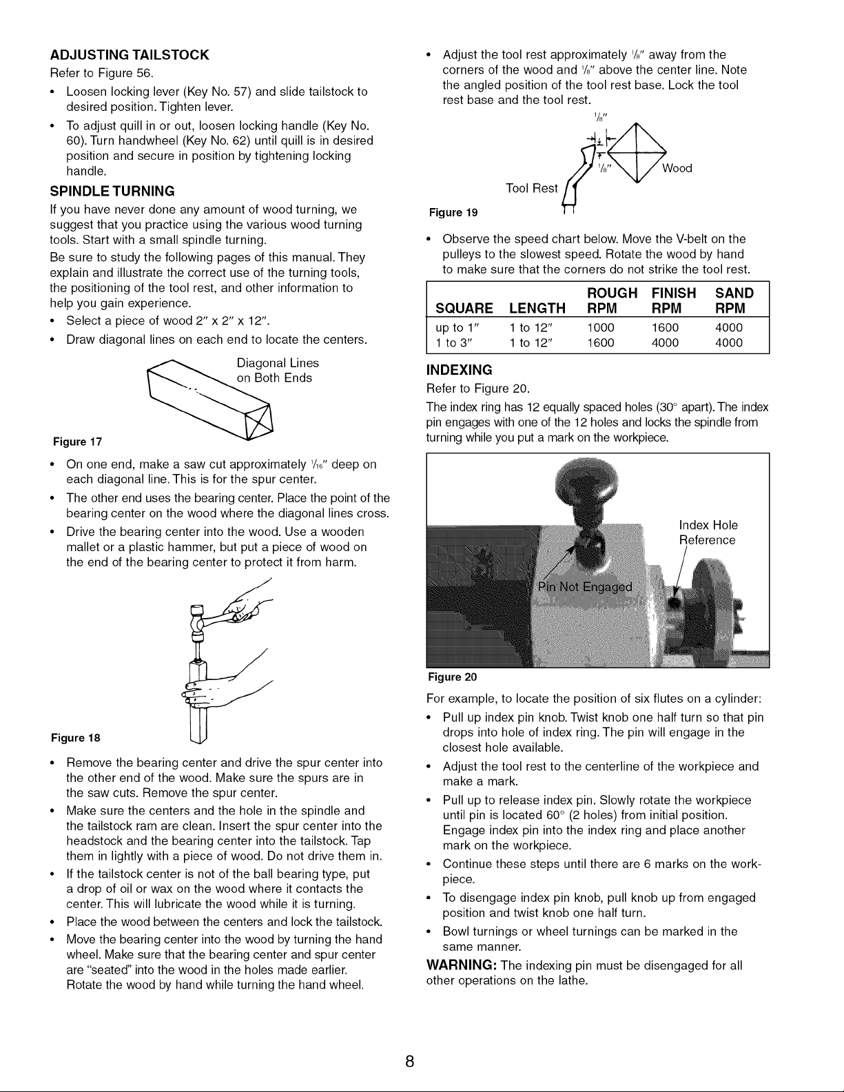
• Grounding plug should be plugged directly into a properly
installed and grounded 3-prong grounding-type receptacle,
as shown (Figure 10).
Properly Grounded Outlet _:
Grounding Prong
3-Prong Plug _
Figure 10 - 3-Prong Receptacle
• Do not remove or alter grounding prong in any manner.
In the event of a malfunction or breakdown, grounding
provides a path of least resistance for electrical shock.
WARNING: Do not permit fingers to touch the terminals
of plug when installing or removing from outlet.
• Plug must be plugged into matching outlet that is properly
installed and grounded in accordance with all local codes
and ordinances. Do not modify plug provided. If it will not fit in
outlet, have proper outlet installed by a qualified electrician.
• Inspect tool cords periodically and if damaged, have
them repaired by an authorized service facility.
• Green (or green and yellow) conductor in cord is the
grounding wire. If repair or replacement of the electric
cord or plug is necessary, do not connect the green
(or green and yellow) wire to a live terminal.
5
• Where a 2-prong wall receptacle is encountered, it must
be replaced with a properly grounded 3-prong receptacle
installed in accordance with National Electric Code and
local codes and ordinances.
WARNING: This work should be performed by a qualified
electrician.
A temporary 3-prong to 2-prong grounding adapter (see
Figure 11) is available for connecting plugs to a two pole
outlet if it is properly grounded.
• Do not use a 3-prong to 2-prong grounding adapter unless
permitted by local and national codes and ordinances.
• (A 3-prong to 2-prong grounding adapter is not permitted
in Canada.) Where permitted, the rigid green tab or termi-
nal on the side of the adapter must be securely connected
to a permanent electrical ground such as a properly
grounded water pipe, a properly grounded outlet box or
a properly grounded wire system.
• Many cover plate screws, water pipes and outlet boxes are
not properly grounded. To ensure proper ground, grounding
means must be tested by a qualified electrician.
Grounding Lug Make Sure
This Is
Adapter Connected To
3-Prong Plug A Known
Ground
2-Prong Receptacle
Figure 11 - 2-Prong Receptacle with Adapter
EXTENSION CORDS
• The use of any extension cord will cause some drop in
voltage and loss of power.
• Wires of the extension cord must be of sufficient size to
carry the current and maintain adequate voltage.
• Use the table to determine the minimum wire size (A.W.G.)
extension cord.
• Use only 3-wire extension cords having 3-prong grounding
type plugs and 3-pole receptacles which accept the tool plug.
• If the extension cord is worn, cut, or damaged in any way,
replace it immediately.
Extension Cord Length
Wire Size A.W.G.
Up to 50 ft....................................... 16
NOTE: Using extension cords over 50 ft. long is not
recommended.
MOTOR
The wood lathe is assembled with motor and wiring installed.
Horsepower (Continuous Duty) ...................... 1/2
Voltage ........................................ 12 0
Amperes ......................................... 6
Hertz .......................................... 6 0
Phase ....................................... Single
RPM ......................................... 3450
ELECTRICAL CONNECTIONS
WARNING: Make sure unit is off and disconnected from
power source before inspecting any wiring.
The lathe is prewired for use on a 120 volt, 60HZ power supply.
The power supply to the motor is controlled by a single pole
locking rocker switch.
The power lines are inserted directly onto the switch. The
green ground line must remain securely fastened to the
frame to properly protect against electrical shock.
• Remove the key to prevent unauthorized use.
Refer to Figures 12- 56.
DESCRIPTION
Craftsman MIDI lathe provides capability to turn wooden work-
pieces up to 16" long and 12" diameter. The motor rotates at
3450 RPM and the spindle speeds are 430-3900 RPM.
SPECIFICATIONS
Max. Distance Between Centers .................... 1 6"
Swing Over Bed ................................. 1 2"
Swing Over Tool Rest Base ....................... 91/2''
Overall Length ................................. 313/4"
Overall Height ................................. 111/2"
Width ......................................... 1 8"
Spindle Speeds (6) ................... 650 to 4000 RPM
Spindle Taper .................................. 2 M T
Spindle Thread ................................. 1"-8
Spindle Thru-Hole .............................. 3/8"
Tailstock Taper ................................. 2 M T
Tailstock Quill Travel ............................. 21/2''
Switch ............................. SP, Locking rocker
Motor ................................ 120V, 6 AMPS
Weight ...................................... 89 Ibs
Shipping Weight .............................. 94 Ibs
WARNING: Operation of any power tool can result in foreign
objects being thrown into the eyes, which can result in severe
eye damage. Always wear safety goggles complying with
Unites States ANSI Z87.1 (shown on package) before com-
mencing power tool operation. Safety goggles are available
at Sears retail stores or catalog.
CAUTION: Always observe the following safety precautions:
SAFETY PRECAUTIONS
• Whenever adjusting or replacing any parts on the tool,
turn switch OFF and remove the plug from power source.
• Recheck all locking handles. They must be tightened securely.
• Make sure all moving parts are free and clear of any
interference.
• Make sure all fasteners are tight and have not vibrated loose.
• With power disconnected, test operation by hand for
clearance and adjust if necessary.
• Always wear eye protection or face shield.
• After turning switch on, always allow the spindle to come
up to full speed before turning.
• Be sure spindle runs counterclockwise when viewing
spindle from the right end (inboard side of headstock).
• Keep hands clear of spindle, centers, faceplates and
other moving parts of machine.
• For optimum performance, do not stall motor or reduce
speed. Do not force the tool into the work.
6
ON-OFF SWITCH
Refer to Figure 56.
• The ON/OFF switch (Key No. 55) is located on the front of
the headstock. To turn lathe ON, pull switch to the up posi-
tion. To turn lathe OFF, push switch to the down position.
The lathe can be locked from unauthorized use by locking
the switch. To lock the switch:
• Turn the switch to OFF position and disconnect lathe from
power source.
• Pull the key out. The switch cannot be turned on with the
key removed.
NOTE: Should the key be removed from the switch at the ON
position, the switch can be turned to OFF position, but cannot
be turned to ON position.
• To replace key, slide key into the slot on switch until it snaps.
CHANGING SPEEDS
Refer to Figures 12 and 13.
WARNING: Disconnect lathe from power before changing
speeds.
• Open headstock cover, loosen locking handle and raise
motor mounting plate lever to release belt tension.
Headstock
Cover
Locking
Motor Mounting Plate Lever Handle
Figure 12 - Changing Speed
• Refer to speed chart and move drive belt to desired speed.
Figure 13 - Speed Chart
B DEF
2 6
A1 - 650 RPM
B2 - 1000 RPM
C3 - 1600 RPM
D4 - 2100 RPM
E5 - 3000 RPM
F6 - 4000 RPM
Push down on motor mounting plate lever to tension belt
and secure plate in position with locking handle. Close
headstock cover.
REMOVAL OF SPUR CENTER FROM SPINDLE
Refer to Figure 14.
• To remove the spur center from the spindle, insert the center
removal rod into the spindle and gently tap the center out.
Center Removal Rod Spur
Center
Figure 14 - Spur Center Removal
REMOVAL OF BEARING CENTER FROM RAM
Refer to Figure 15.
• To remove live center from tailstock quill, loosen locking
handle and turn handwheel counterclockwise. The live
center will be pushed out of quill.
Live Center Locking Handwheel
Handle
Figure 15
INSTALLING/REMOVING FACEPLATE
Refer to Figure 16.
• Insert rod into spindle to lock spindle. Use provided wrench
to install or remove faceplate.
Figure 16
ADJUSTING TOOL REST
Refer to Figure 56.
• Loosen locking lever (Key No. 69), slide tool rest base to
desired position and secure in position.
• Loosen locking handle (Key No. 43) and raise or lower
tool rest to desired position.
7
ADJUSTING TAILSTOCK
Refer to Figure 56.
• Loosen locking lever (Key No. 57) and slide tailstock to
desired position. Tighten lever.
• To adjust quill in or out, loosen locking handle (Key No.
60). Turn handwheel (Key No. 62) until quill is in desired
position and secure in position by tightening locking
handle.
SPINDLE TURNING
If you have never done any amount of wood turning, we
suggest that you practice using the various wood turning
tools. Start with a small spindle turning.
Be sure to study the following pages of this manual. They
explain and illustrate the correct use of the turning tools,
the positioning of the tool rest, and other information to
help you gain experience.
• Select a piece of wood 2" x 2" x 12".
• Draw diagonal lines on each end to locate the centers.
Diagonal Lines
on Both Ends
Figure 17
• On one end, make a saw cut approximately 1/16tt deep on
each diagonal line. This is for the spur center.
• The other end uses the bearing center. Place the point of the
bearing center on the wood where the diagonal lines cross.
• Drive the bearing center into the wood. Use a wooden
mallet or a plastic hammer, but put a piece of wood on
the end of the bearing center to protect it from harm.
Figure 19
Adjust the tool rest approximately 1/aftaway from the
corners of the wood and 1/8"above the center line. Note
the angled position of the tool rest base. Lock the tool
rest base and the tool rest.
l/stY
oo,
• Observe the speed chart below. Move the V-belt on the
pulleys to the slowest speed. Rotate the wood by hand
to make sure that the corners do not strike the tool rest.
ROUGH FINISH SAND
SQUARE LENGTH RPM RPM RPM
up to 1" 1to 12" 1000 1600 4000
1 to 3" 1to 12" 1600 4000 4000
INDEXING
Refer to Figure 20.
The index ring has 12 equally spaced holes (30° apart).The index
pin engages with one of the 12 holes and locks the spindle from
turning while you put a mark on the workpiece.
Index Hole
Reference
Figure 18
• Remove the bearing center and drive the spur center into
the other end of the wood. Make sure the spurs are in
the saw cuts. Remove the spur center.
• Make sure the centers and the hole in the spindle and
the tailstock ram are clean. Insert the spur center into the
headstock and the bearing center into the tailstock. Tap
them in lightly with a piece of wood. Do not drive them in.
• If the tailstock center is not of the ball bearing type, put
a drop of oil or wax on the wood where it contacts the
center. This will lubricate the wood while it is turning.
• Place the wood between the centers and lock the tailstock.
• Move the bearing center into the wood by turning the hand
wheel. Make sure that the bearing center and spur center
are "seated" into the wood in the holes made earlier.
Rotate the wood by hand while turning the hand wheel.
Figure 20
For example, to locate the position of six flutes on a cylinder:
• Pull up index pin knob. Twist knob one half turn so that pin
drops into hole of index ring. The pin will engage in the
closest hole available.
• Adjust the tool rest to the centerline of the workpiece and
make a mark.
• Pull up to release index pin. Slowly rotate the workpiece
until pin is located 60 ° (2 holes) from initial position.
Engage index pin into the index ring and place another
mark on the workpiece.
• Continue these steps until there are 6 marks on the work-
piece.
• To disengage index pin knob, pull knob up from engaged
position and twist knob one half turn.
• Bowl turnings or wheel turnings can be marked in the
same manner.
WARNING: The indexing pin must be disengaged for all
other operations on the lathe.
8
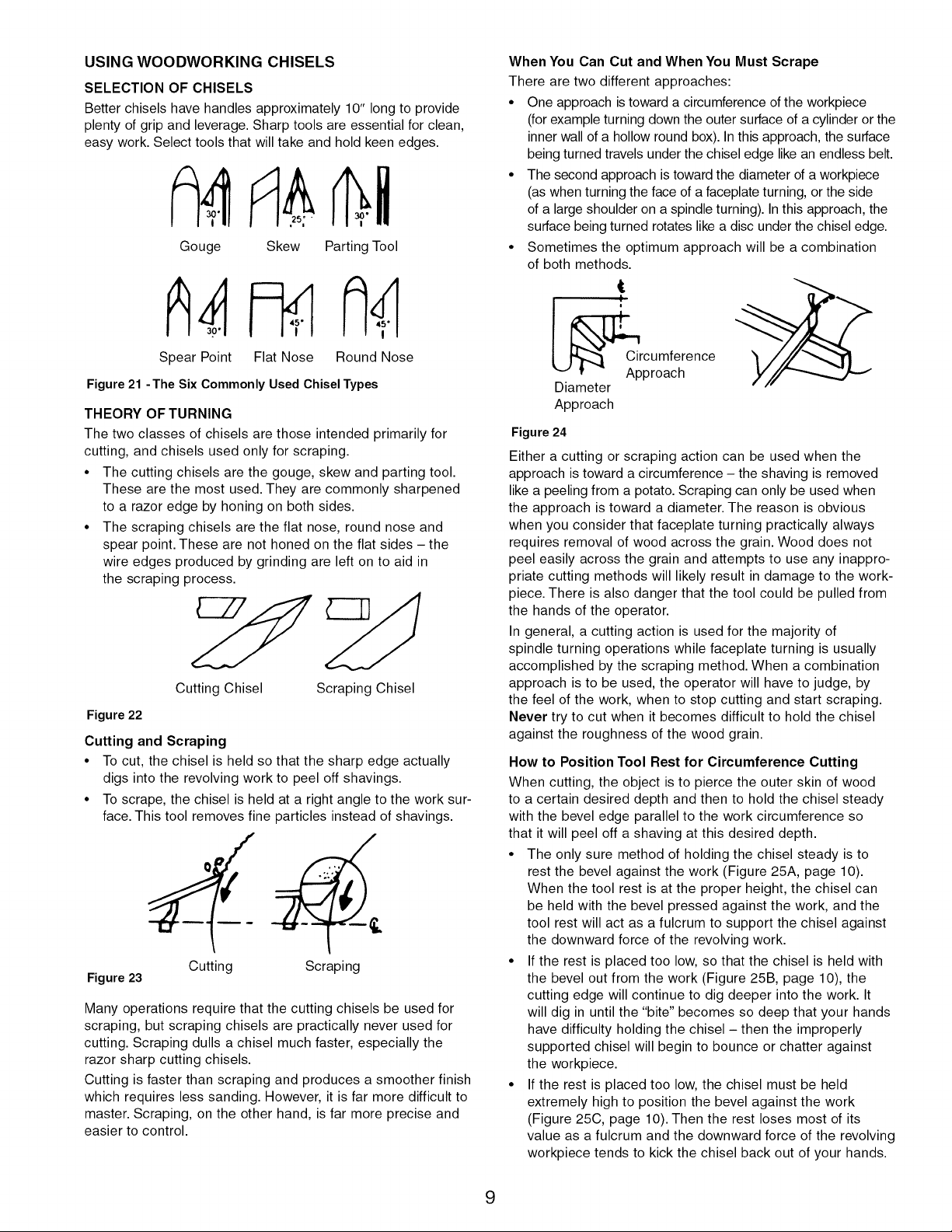
USING WOODWORKING CHISELS
SELECTION OF CHISELS
Better chisels have handles approximately 10" long to provide
plenty of grip and leverage. Sharp tools are essential for clean,
easy work. Select tools that will take and hold keen edges.
Gouge Skew Parting Tool
Spear Point Flat Nose
Round Nose
Figure 21 -The Six Commonly Used Chisel Types
THEORY OF TURNING
The two classes of chisels are those intended primarily for
cutting, and chisels used only for scraping.
• The cutting chisels are the gouge, skew and parting tool.
These are the most used. They are commonly sharpened
to a razor edge by honing on both sides.
• The scraping chisels are the flat nose, round nose and
spear point. These are not honed on the flat sides - the
wire edges produced by grinding are left on to aid in
the scraping process.
Cutting Chisel Scraping Chisel
Figure 22
Cutting and Scraping
• To cut, the chisel is held so that the sharp edge actually
digs into the revolving work to peel off shavings.
• To scrape, the chisel is held at a right angle to the work sur-
face. This tool removes fine particles instead of shavings.
Figure 23
Cutting Scraping
Many operations require that the cutting chisels be used for
scraping, but scraping chisels are practically never used for
cutting. Scraping dulls a chisel much faster, especially the
razor sharp cutting chisels.
Cutting is faster than scraping and produces a smoother finish
which requires less sanding. However, it is far more difficult to
master. Scraping, on the other hand, is far more precise and
easier to control.
When You Can Cut and When You Must Scrape
There are two different approaches:
• One approach is toward a circumference of the workpiece
(for example turning down the outer surface of a cylinder or the
inner wall of a hollow round box). In this approach, the surface
being turned travels under the chisel edge like an endless belt.
• The second approach is toward the diameter of a workpiece
(as when turning the face of a faceplate turning, or the side
of a large shoulder on a spindle turning). In this approach, the
surface being turned rotates like a disc under the chisel edge.
• Sometimes the optimum approach will be a combination
of both methods.
Ap__Cr; _omfehence
Diameter
Approach
Figure 24
Either a cutting or scraping action can be used when the
approach is toward a circumference - the shaving is removed
like a peeling from a potato. Scraping can only be used when
the approach is toward a diameter. The reason is obvious
when you consider that faceplate turning practically always
requires removal of wood across the grain. Wood does not
peel easily across the grain and attempts to use any inappro-
priate cutting methods will likely result in damage to the work-
piece. There is also danger that the tool could be pulled from
the hands of the operator.
In general, a cutting action is used for the majority of
spindle turning operations while faceplate turning is usually
accomplished by the scraping method. When a combination
approach is to be used, the operator will have to judge, by
the feel of the work, when to stop cutting and start scraping.
Never try to cut when it becomes difficult to hold the chisel
against the roughness of the wood grain.
How to Position Tool Rest for Circumference Cutting
When cutting, the object is to pierce the outer skin of wood
to a certain desired depth and then to hold the chisel steady
with the bevel edge parallel to the work circumference so
that it will peel off a shaving at this desired depth.
• The only sure method of holding the chisel steady is to
rest the bevel against the work (Figure 25A, page 10).
When the tool rest is at the proper height, the chisel can
be held with the bevel pressed against the work, and the
tool rest will act as a fulcrum to support the chisel against
the downward force of the revolving work.
• If the rest is placed too low, so that the chisel is held with
the bevel out from the work (Figure 25B, page 10), the
cutting edge will continue to dig deeper into the work. It
will dig in until the "bite" becomes so deep that your hands
have difficulty holding the chisel - then the improperly
supported chisel will begin to bounce or chatter against
the workpiece.
• If the rest is placed too low, the chisel must be held
extremely high to position the bevel against the work
(Figure 25C, page 10). Then the rest loses most of its
value as a fulcrum and the downward force of the revolving
workpiece tends to kick the chisel back out of your hands.
9
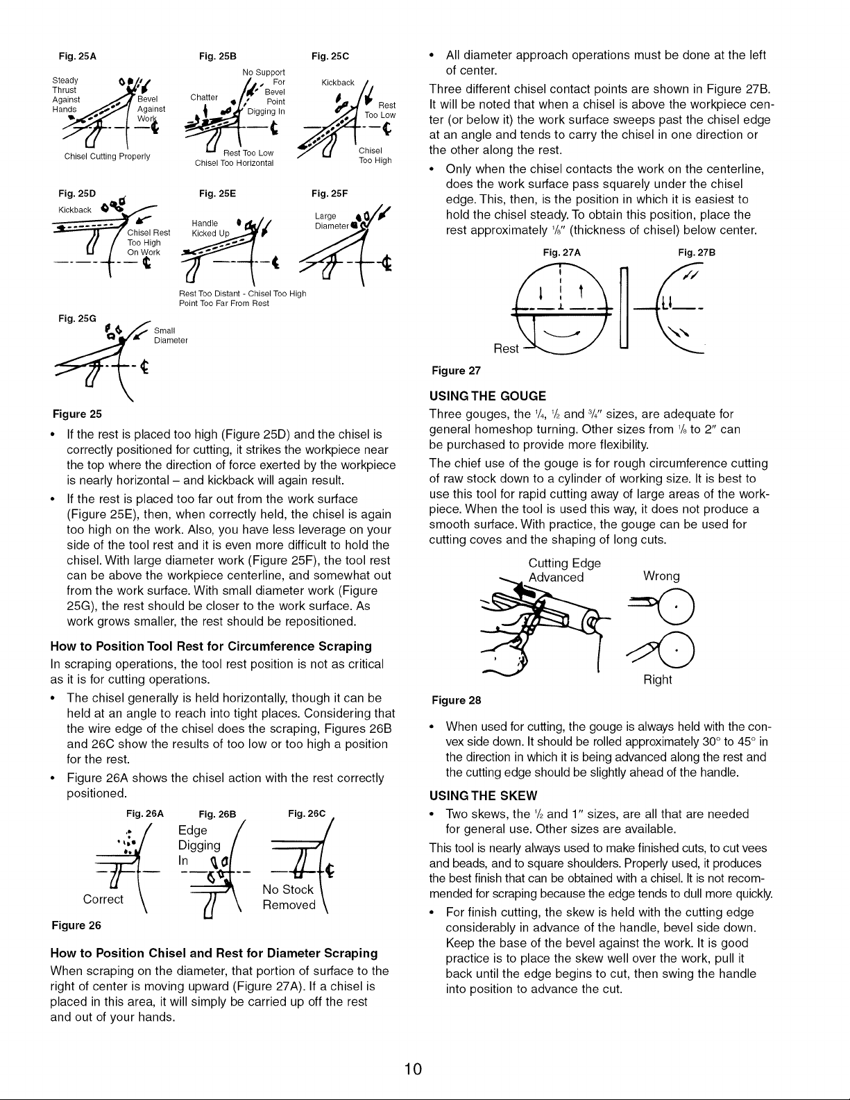
Fig. 25A
Steady (_ Im/a i
Thrust "_'_
Against __,,_o.A Bevel
Hands _._"'_/ Against
Chisel Cutting Properly
Fig. 25B
No Support
/,t.'BF,;r,
Chatter ! ;," Pgi/t
o Lo
Chisel Too Horizontal
Fig. 25C
Kickback
Rest
Too Low
Chisel
Too High
Fig. 25D
Kickback __
.
Chisel Rest
Too High
On Work
Fig. 25E
Handle 0d_'./
Fig. 25F
Rest Too Distant - Chisel Too High
Point Too Far From Rest
_ Sti_leter
Figure 25
If the rest is placed too high (Figure 25D) and the chisel is
correctly positioned for cutting, it strikes the workpiece near
the top where the direction of force exerted by the workpiece
is nearly horizontal - and kickback will again result.
If the rest is placed too far out from the work surface
(Figure 25E), then, when correctly held, the chisel is again
too high on the work. Also, you have less leverage on your
side of the tool rest and it is even more difficult to hold the
chisel. With large diameter work (Figure 25F), the tool rest
can be above the workpiece centerline, and somewhat out
from the work surface. With small diameter work (Figure
25G), the rest should be closer to the work surface. As
work grows smaller, the rest should be repositioned.
How to Position Tool Rest for Circumference Scraping
In scraping operations, the tool rest position is not as critical
as it is for cutting operations.
• The chisel generally is held horizontally, though it can be
held at an angle to reach into tight places. Considering that
the wire edge of the chisel does the scraping, Figures 26B
and 26C show the results of too low or too high a position
for the rest.
• Figure 26A shows the chisel action with the rest correctly
positioned.
Fig. 26A Fig. 26B Fig. 260
.; Edge N_
.... Digging
In
Correct
Figure 26
How to Position Chisel and Rest for Diameter Scraping
When scraping on the diameter, that portion of surface to the
right of center is moving upward (Figure 27A). If a chisel is
placed in this area, it will simply be carried up off the rest
and out of your hands.
• All diameter approach operations must be done at the left
of center.
Three different chisel contact points are shown in Figure 27B.
It will be noted that when a chisel is above the workpiece cen-
ter (or below it) the work surface sweeps past the chisel edge
at an angle and tends to carry the chisel in one direction or
the other along the rest.
• Only when the chisel contacts the work on the centerline,
does the work surface pass squarely under the chisel
edge. This, then, is the position in which it is easiest to
hold the chisel steady. To obtain this position, place the
rest approximately 1/8"(thickness of chisel) below center.
Fig. 27A
es@
Fig. 27B
U___
Figure 27
USING THE GOUGE
Three gouges, the 1/4, 1/2and 8/4"sizes, are adequate for
general homeshop turning. Other sizes from 1/8to 2" can
be purchased to provide more flexibility.
The chief use of the gouge is for rough circumference cutting
of raw stock down to a cylinder of working size. It is best to
use this tool for rapid cutting away of large areas of the work-
piece. When the tool is used this way, it does not produce a
smooth surface. With practice, the gouge can be used for
cutting coves and the shaping of long cuts.
Cutting Edge
Advanced
Wrong
Right
Figure 28
When used for cutting, the gouge is always held with the con-
vex side down. It should be rolled approximately 30 ° to 45° in
the direction in which it is being advanced along the rest and
the cutting edge should be slightly ahead of the handle.
USING THE SKEW
• Two skews, the 1/2and 1" sizes, are all that are needed
for general use. Other sizes are available.
This tool is nearly always used to make finished cuts, to cut vees
and beads, and to square shoulders. Properly used, it produces
the best finish that can be obtained with a chisel. It is not recom-
mended for scraping because the edge tends to dull more quickly.
• For finish cutting, the skew is held with the cutting edge
considerably in advance of the handle, bevel side down.
Keep the base of the bevel against the work. It is good
practice is to place the skew well over the work, pull it
back until the edge begins to cut, then swing the handle
into position to advance the cut.
10
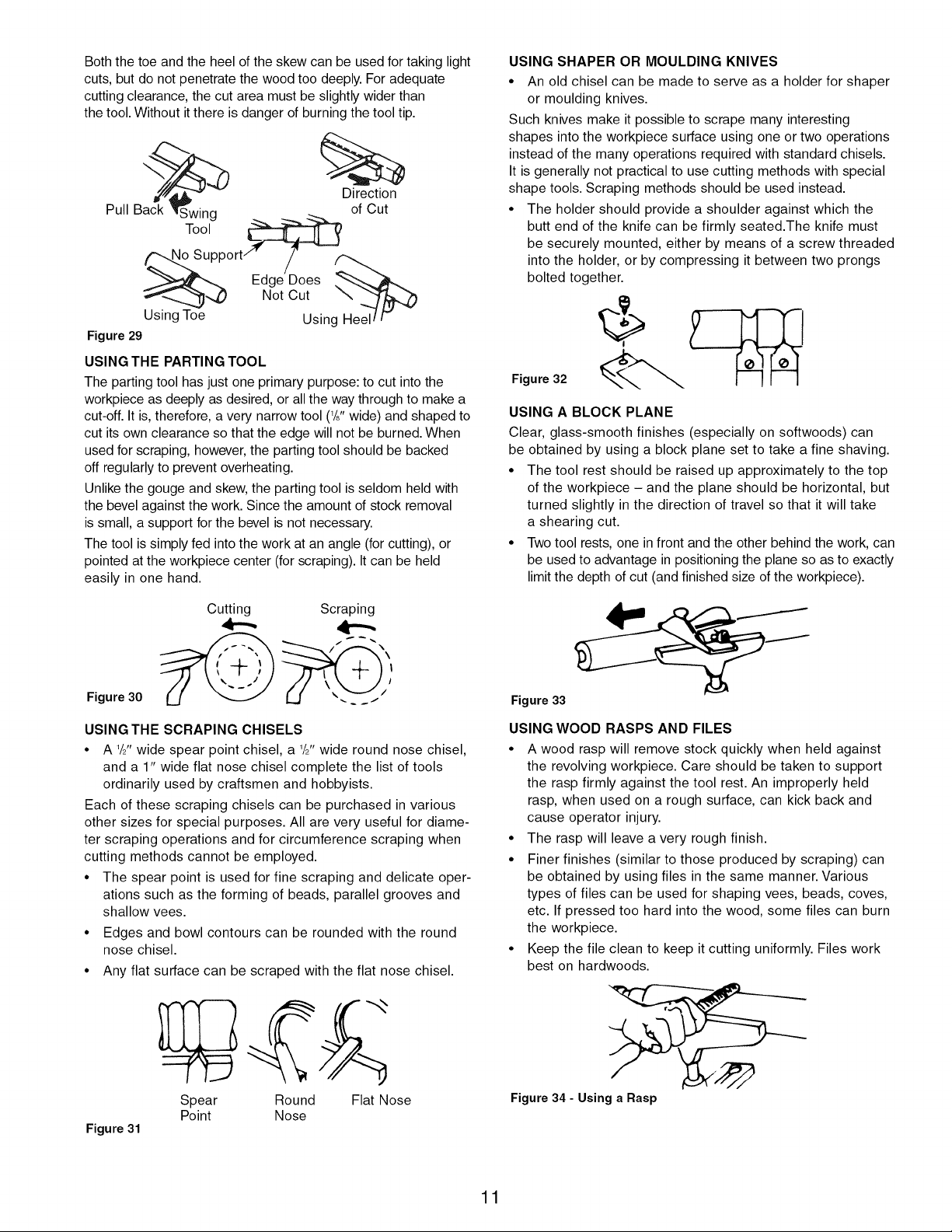
Both the toe and the heel of the skew can be used for taking light
cuts, but do not penetrate the wood too deeply. For adequate
cutting clearance, the cut area must be slightly wider than
the tool. Without it there is danger of burning the tool tip.
Direction
Pull Tool _ of Cut
Back Swing __ --_ .__
_upport/' /
Edge Does
T_-_ _,,_) Not Cut
Using Toe Using
Figure 29
USING THE PARTING TOOL
The parting tool has just one primary purpose: to cut into the
workpiece as deeply as desired, or all the way through to make a
cut-off. It is, therefore, a very narrow tool (l/j, wide) and shaped to
cut its own clearance so that the edge will not be burned. When
used for scraping, however, the parting tool should be backed
off regularly to prevent overheating.
Unlike the gouge and skew, the parting tool is seldom held with
the bevel against the work. Since the amount of stock removal
is small, a support for the bevel is not necessary.
The tool is simply fed into the work at an angle (for cutting), or
pointed at the workpiece center (for scraping). It can be held
easily in one hand.
Figure 30
Cutting Scraping
,4--,,
USING THE SCRAPING CHISELS
• A 1/21twide spear point chisel, a 1/2"wide round nose chisel,
and a 1" wide flat nose chisel complete the list of tools
ordinarily used by craftsmen and hobbyists.
Each of these scraping chisels can be purchased in various
other sizes for special purposes. All are very useful for diame-
ter scraping operations and for circumference scraping when
cutting methods cannot be employed.
• The spear point is used for fine scraping and delicate oper-
ations such as the forming of beads, parallel grooves and
shallow vees.
• Edges and bowl contours can be rounded with the round
nose chisel.
• Any flat surface can be scraped with the flat nose chisel.
Figure 31
Spear Round Flat Nose
Point Nose
USING SHAPER OR MOULDING KNIVES
• An old chisel can be made to serve as a holder for shaper
or moulding knives.
Such knives make it possible to scrape many interesting
shapes into the workpiece surface using one or two operations
instead of the many operations required with standard chisels.
It is generally not practical to use cutting methods with special
shape tools. Scraping methods should be used instead.
• The holder should provide a shoulder against which the
butt end of the knife can be firmly seated.The knife must
be securely mounted, either by means of a screw threaded
into the holder, or by compressing it between two prongs
bolted together.
Figure 32
USING A BLOCK PLANE
Clear, glass-smooth finishes (especially on softwoods) can
be obtained by using a block plane set to take a fine shaving.
• The tool rest should be raised up approximately to the top
of the workpiece - and the plane should be horizontal, but
turned slightly in the direction of travel so that it will take
a shearing cut.
• Two tool rests, one in front and the other behind the work, can
be used to advantage in positioning the plane so as to exactly
limit the depth of cut (and finished size of the workpiece).
Figure 33
USING WOOD RASPS AND FILES
• A wood rasp will remove stock quickly when held against
the revolving workpiece. Care should be taken to support
the rasp firmly against the tool rest. An improperly held
rasp, when used on a rough surface, can kick back and
cause operator injury.
• The rasp will leave a very rough finish.
• Finer finishes (similar to those produced by scraping) can
be obtained by using files in the same manner. Various
types of files can be used for shaping vees, beads, coves,
etc. If pressed too hard into the wood, some files can burn
the workpiece.
• Keep the file clean to keep it cutting uniformly. Files work
best on hardwoods.
Figure 34 - Using a Rasp
11
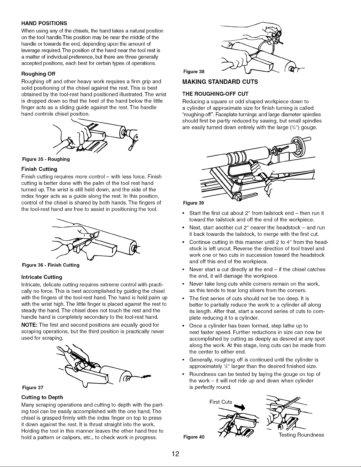
HAND POSITIONS
When using any of the chisels, the hand takes a natural position
on the tool handle.This position may be near the middle of the
handle or towards the end, depending upon the amount of
leverage required. The position of the hand near the tool rest is
a matter of individual preference, but there are three generally
accepted positions, each best for certain types of operations.
Roughing Off
Roughing off and other heavy work requires a firm grip and
solid positioning of the chisel against the rest. This is best
obtained by the tool-rest hand positioned illustrated. The wrist
is dropped down so that the heel of the hand below the little
finger acts as a sliding guide against the rest. The handle
hand controls chisel position.
Figure 38
MAKING STANDARD CUTS
THE ROUGHING-OFF CUT
Reducing a square or odd shaped workpiece down to
a cylinder of approximate size for finish turning is called
"roughing-off". Faceplate turnings and large diameter spindles
should first be partly reduced by sawing, but small spindles
are easily turned down entirely with the large (3/4")gouge.
Figure 35 - Roughing
Finish Cutting
Finish cutting requires more control - with less force. Finish
cutting is better done with the palm of the tool rest hand
turned up. The wrist is still held down, and the side of the
index finger acts as a guide along the rest. In this position,
control of the chisel is shared by both hands. The fingers of
the tool-rest hand are free to assist in positioning the tool.
Figure 36 - Finish Cutting
Intricate Cutting
Intricate, delicate cutting requires extreme control with practi-
cally no force. This is best accomplished by guiding the chisel
with the fingers of the tool-rest hand. The hand is held palm up
with the wrist high. The little finger is placed against the rest to
steady the hand. The chisel does not touch the rest and the
handle hand is completely secondary to the tool-rest hand.
NOTE: The first and second positions are equally good for
scraping operations, but the third position is practically never
used for scraping.
Figure 37
Cutting to Depth
Many scraping operations and cutting to depth with the part-
ing tool can be easily accomplished with the one hand. The
chisel is grasped firmly with the index finger on top to press
it down against the rest. It is thrust straight into the work.
Holding the tool in this manner leaves the other hand free to
hold a pattern or calipers, etc., to check work in progress.
Figure 39
• Start the first cut about 2" from tailstock end - then run it
toward the tailstock and off the end of the workpiece.
• Next, start another cut 2" nearer the headstock - and run
it back towards the tailstock, to merge with the first cut.
• Continue cutting in this manner until 2 to 4" from the head-
stock is left uncut. Reverse the direction of tool travel and
work one or two cuts in succession toward the headstock
and off this end of the workpiece.
• Never start a cut directly at the end - if the chisel catches
the end, it will damage the workpiece.
• Never take long cuts while corners remain on the work,
as this tends to tear long slivers from the corners.
• The first series of cuts should not be too deep. It is
better to partially reduce the work to a cylinder all along
its length. After that, start a second series of cuts to com-
plete reducing it to a cylinder.
• Once a cylinder has been formed, step lathe up to
next faster speed. Further reductions in size can now be
accomplished by cutting as deeply as desired at any spot
along the work. At this stage, long cuts can be made from
the center to either end.
• Generally, roughing off is continued until the cylinder is
approximately 1/8"larger than the desired finished size.
• Roundness can be tested by laying the gouge on top of
the work - it will not ride up and down when cylinder
is perfectly round.
Figure 40
First Cuts
Testing Roundness
12
ROUGH-CUTTING TO SIZE
The roughing-off cut can be made to accurately size the
cylinder to a given diameter.
Another method is to make a number of sizing cuts at inter-
vals along the work, then use the gouge to reduce the whole
cylinder down to the diameter indicated by these cuts.
MAKING SIZING CUTS
Sizing cuts are useful to establish approximate finished size
diameters at various points along a workpiece. The work can
then be turned down to the diameters indicated and be ready
for finishing.
• Diameters for sizing cuts should be planned to be about 1/8"
greater than the desired finish diameters. A sizing cut is
made with the parting tool.
• Hold the tool in one hand, and use the other hand to hold
an outside caliper preset to the desired sizing-cut diameter.
• As the cut nears completion, lower the chisel point more
and more into a scraping position.
• When the calipers slip over the workpiece at the bottom
of the groove, then the cut is finished.
Figure 41
SMOOTHING A CYLINDER
The final 1/8"can be removed in two ways. Either use the 1"
skew, working from the center toward both ends and taking
lighter and lighter cuts until finished, or use a block plane
as illustrated in Figure 29.
CUTTING A SHOULDER
A shoulder can be the side of a square portion left in the
workpiece, the side of a turned section, or the end of the
workpiece. Most shoulders are perpendicular to the work
axis, but a shoulder can be at any angle.
• First, mark position of the shoulder with a pencil held to
the revolving workpiece.
• Second, make a sizing cut with the parting tool, placing
this cut about 1/16"outside the shoulder position and cutting
to within about 1/8"of the depth desired for the area outside
of the shoulder.
• If shoulder is shallow, the toe of the skew can be used
to make the sizing cut. Do not go in deeper than 1/8"with
the skew unless wider and wider vees are cut to provide
clearance for this tool.
Figure 42 "_
• Use the gouge to remove any waste stock outside of shoul-
der. Smooth this section, up to within 1/8"of shoulder, in the
usual manner. Finishing of the shoulder, unless it is more
than 1" high, is best done with the 1/8"skew.
13
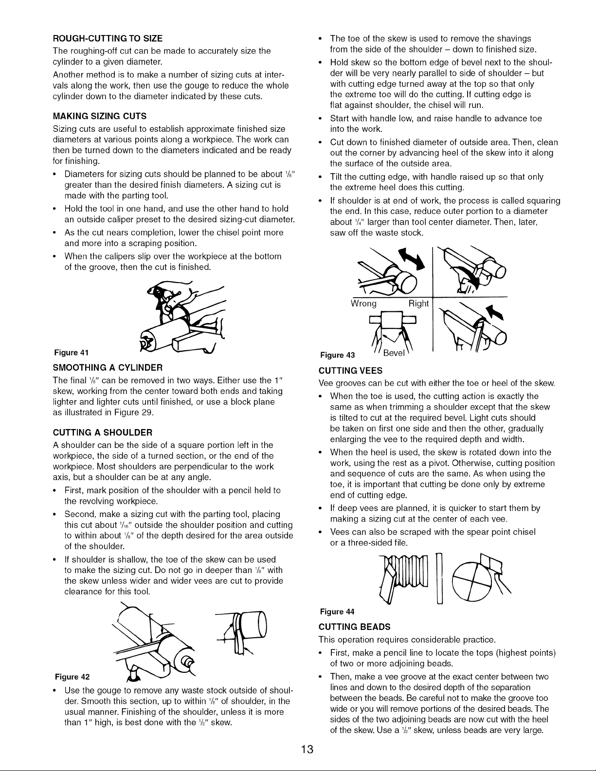
• The toe of the skew is used to remove the shavings
from the side of the shoulder - down to finished size.
• Hold skew so the bottom edge of bevel next to the shoul-
der will be very nearly parallel to side of shoulder - but
with cutting edge turned away at the top so that only
the extreme toe will do the cutting. If cutting edge is
flat against shoulder, the chisel will run.
• Start with handle low, and raise handle to advance toe
into the work.
• Cut down to finished diameter of outside area. Then, clean
out the corner by advancing heel of the skew into it along
the surface of the outside area.
• Tilt the cutting edge, with handle raised up so that only
the extreme heel does this cutting.
• If shoulder is at end of work, the process is called squaring
the end. In this case, reduce outer portion to a diameter
about 1/4"larger than tool center diameter. Then, later,
saw off the waste stock.
Wrong Right
Figure 43
CUTTING VEES
Vee grooves can be cut with either the toe or heel of the skew.
• When the toe is used, the cutting action is exactly the
same as when trimming a shoulder except that the skew
is tilted to cut at the required bevel. Light cuts should
be taken on first one side and then the other, gradually
enlarging the vee to the required depth and width.
• When the heel is used, the skew is rotated down into the
work, using the rest as a pivot. Otherwise, cutting position
and sequence of cuts are the same. As when using the
toe, it is important that cutting be done only by extreme
end of cutting edge.
• If deep vees are planned, it is quicker to start them by
making a sizing cut at the center of each vee.
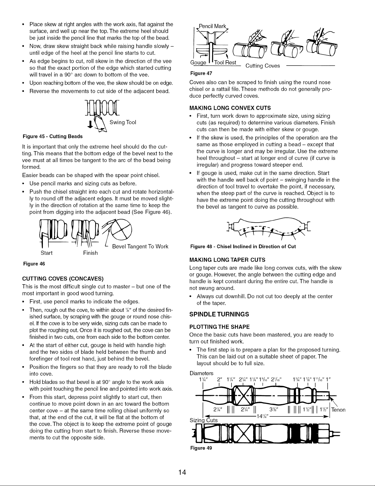
• Vees can also be scraped with the spear point chisel
or a three-sided file.
Figure 44
CUTTING BEADS
This operation requires considerable practice.
• First, make a pencil line to locate the tops (highest points)
of two or more adjoining beads.
• Then, make a vee groove at the exact center between two
lines and down to the desired depth of the separation
between the beads. Be careful not to make the groove too
wide or you will remove portions of the desired beads. The
sides of the two adjoining beads are now cut with the heel
of the skew. Use a 1/8"skew, unless beads are very large.
• Placeskewatrightangleswiththeworkaxis,flatagainstthe
surface,andwellupnearthetop.Theextremeheelshould
bejustinsidethepencillinethatmarksthetopofthebead.
• Now,drawskewstraightbackwhileraisinghandleslowly-
untiledgeoftheheelatthepencillinestartstocut.
• Asedgebeginstocut,rollskewinthedirectionofthevee
sothattheexactportionoftheedgewhichstartedcutting
willtravelina90°arcdowntobottomofthevee.
• Uponreachingbottomofthevee,theskewshouldbeonedge.
• Reversethemovementstocutsideoftheadjacentbead.
_' SwingTool
Figure 45 - Cutting Beads
It is important that only the extreme heel should do the cut-
ting. This means that the bottom edge of the bevel next to the
vee must at all times be tangent to the arc of the bead being
formed.
Easier beads can be shaped with the spear point chisel.
• Use pencil marks and sizing cuts as before.
• Push the chisel straight into each cut and rotate horizontal-
ly to round off the adjacent edges. It must be moved slight-
ly in the direction of rotation at the same time to keep the
point from digging into the adjacent bead (See Figure 46).
B_evel Tangent To Work
Start Finish
Figure 46
CUTTING COVES (CONCAVES)
This is the most difficult single cut to master - but one of the
most important in good wood turning.
• First, use pencil marks to indicate the edges.
• Then, rough out the cove, to within about '/8" of the desired fin-
ished surface, by scraping with the gouge or round nose chis-
el. If the cove is to be very wide, sizing cuts can be made to
plot the roughing out. Once it is roughed out, the cove can be
finished in two cuts, one from each side to the bottom center.
• At the start of either cut, gouge is held with handle high
and the two sides of blade held between the thumb and
forefinger of tool rest hand, just behind the bevel.
• Position the fingers so that they are ready to roll the blade
into cove.
• Hold blades so that bevel is at 90° angle to the work axis
with point touching the pencil line and pointed into work axis.
• From this start, depress point slightly to start cut, then
continue to move point down in an arc toward the bottom
center cove - at the same time rolling chisel uniformly so
that, at the end of the cut, it will be flat at the bottom of
the cove. The object is to keep the extreme point of gouge
doing the cutting from start to finish. Reverse these move-
ments to cut the opposite side.
_Pencil Mark
e Cutting Coves
Figure 47
Coves also can be scraped to finish using the round nose
chisel or a rattail file. These methods do not generally pro-
duce perfectly curved coves.
MAKING LONG CONVEX CUTS
• First, turn work down to approximate size, using sizing
cuts (as required) to determine various diameters. Finish
cuts can then be made with either skew or gouge.
• If the skew is used, the principles of the operation are the
same as those employed in cutting a bead - except that
the curve is longer and may be irregular. Use the extreme
heel throughout - start at longer end of curve (if curve is
irregular) and progress toward steeper end.
• If gouge is used, make cut in the same direction. Start
with the handle well back of point - swinging handle in the
direction of tool travel to overtake the point, if necessary,
when the steep part of the curve is reached. Object is to
have the extreme point doing the cutting throughout with
the bevel as tangent to curve as possible.
Figure 48 - Chisel Inclined in Direction of Cut
MAKING LONG TAPER CUTS
Long taper cuts are made like long convex cuts, with the skew
or gouge. However, the angle between the cutting edge and
handle is kept constant during the entire cut. The handle is
not swung around.
• Always cut downhill. Do not cut too deeply at the center
of the taper.
SPINDLE TURNINGS
PLOTTING THE SHAPE
Once the basic cuts have been mastered, you are ready to
turn out finished work.
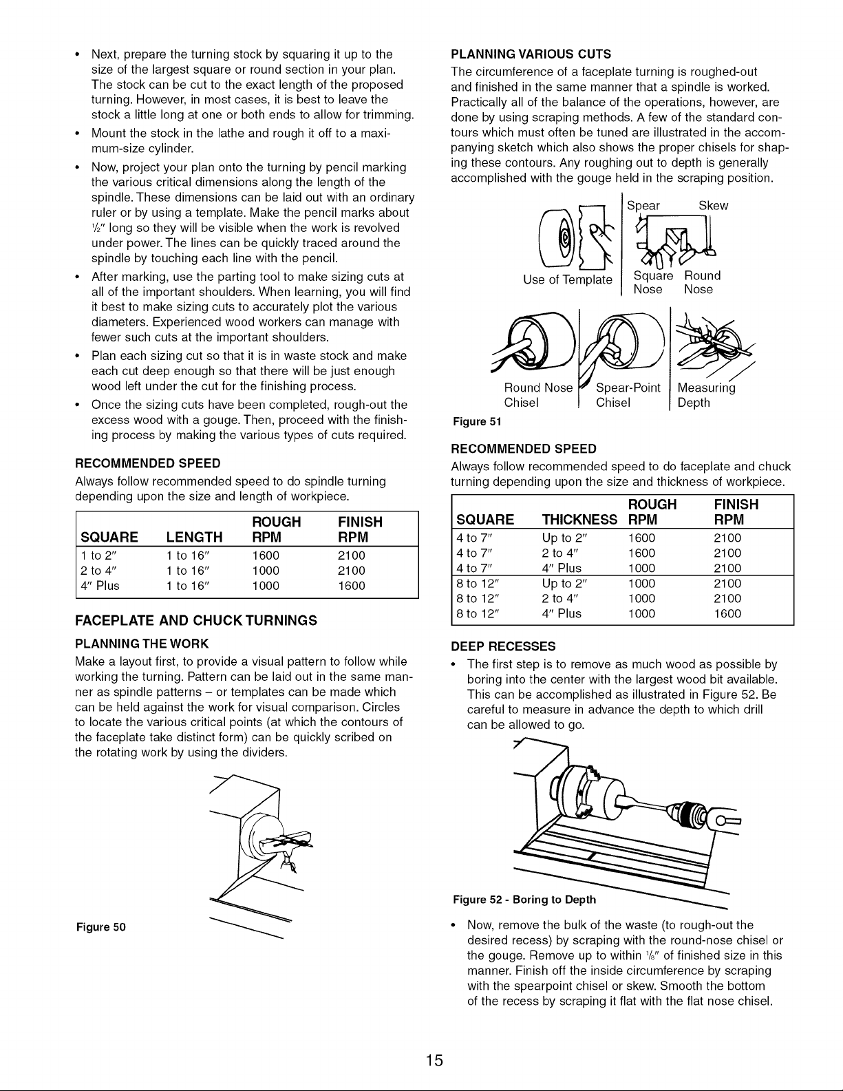
• The first step is to prepare a plan for the proposed turning.
This can be laid out on a suitable sheet of paper. The
layout should be to full size.
Diameters
lY4" 2" 1W' 2W' 1W'19/16"21/,6" 13/4'' 17/j' 1'1/16'' 1"
_non
I ,_ 141/4" _,. I
Sizing Cuts
Figure 49
14
• Next, prepare the turning stock by squaring it up to the
size of the largest square or round section in your plan.
The stock can be cut to the exact length of the proposed
turning. However, in most cases, it is best to leave the
stock a little long at one or both ends to allow for trimming.
• Mount the stock in the lathe and rough it off to a maxi-
mum-size cylinder.
• Now, project your plan onto the turning by pencil marking
the various critical dimensions along the length of the
spindle. These dimensions can be laid out with an ordinary
ruler or by using a template. Make the pencil marks about
W' long so they will be visible when the work is revolved
under power. The lines can be quickly traced around the
spindle by touching each line with the pencil.
• After marking, use the parting tool to make sizing cuts at
all of the important shoulders. When learning, you will find
it best to make sizing cuts to accurately plot the various
diameters. Experienced wood workers can manage with
fewer such cuts at the important shoulders.
• Plan each sizing cut so that it is in waste stock and make
each cut deep enough so that there will be just enough
wood left under the cut for the finishing process.
• Once the sizing cuts have been completed, rough-out the
excess wood with a gouge. Then, proceed with the finish-
ing process by making the various types of cuts required.
RECOMMENDED SPEED
Always follow recommended speed to do spindle turning
depending upon the size and length of workpiece.
ROUGH FINISH
SQUARE LENGTH RPM RPM
1 to 2" 1 to 16" 1600 2100
2 to 4" 1 to 16" 1000 2100
4" Plus 1 to 16" 1000 1600
FACEPLATE AND CHUCK TURNINGS
PLANNING THE WORK
Make a layout first, to provide a visual pattern to follow while
working the turning. Pattern can be laid out in the same man-
ner as spindle patterns - or templates can be made which
can be held against the work for visual comparison. Circles
to locate the various critical points (at which the contours of
the faceplate take distinct form) can be quickly scribed on
the rotating work by using the dividers.
Figure 50
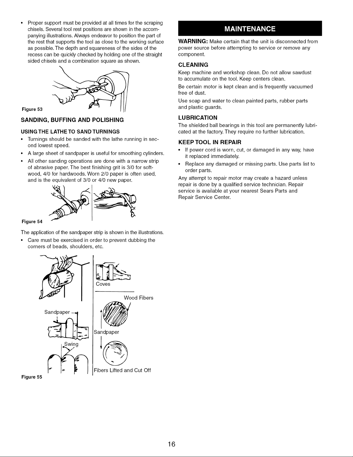
PLANNING VARIOUS CUTS
The circumference of a faceplate turning is roughed-out
and finished in the same manner that a spindle is worked.
Practically all of the balance of the operations, however, are
done by using scraping methods. A few of the standard con-
tours which must often be tuned are illustrated in the accom-
panying sketch which also shows the proper chisels for shap-
ing these contours. Any roughing out to depth is generally
accomplished with the gouge held in the scraping position.
Use of Template
Spear Skew
Square Round
Nose Nose
Round Nose
Chisel
Figure 51
Chisel
Measuring
Depth
RECOMMENDED SPEED
Always follow recommended speed to do faceplate and chuck
turning depending upon the size and thickness of workpiece.
ROUGH FINISH
SQUARE THICKNESS RPM RPM
4 to 7" Up to 2" 1600 2100
4 to 7" 2 to 4" 1600 2100
4 to 7" 4" Plus 1000 2100
8 to 12" Up to 2" 1000 2100
8 to 12" 2 to 4" 1000 2100
8 to 12" 4" Plus 1000 1600
DEEP RECESSES
• The first step is to remove as much wood as possible by
boring into the center with the largest wood bit available.
This can be accomplished as illustrated in Figure 52. Be
careful to measure in advance the depth to which drill
can be allowed to go.
O==
Figure 52 - Boring to Depth
• Now, remove the bulk of the waste (to rough-out the
desired recess) by scraping with the round-nose chisel or
the gouge. Remove up to within _/8"of finished size in this
manner. Finish off the inside circumference by scraping
with the spearpoint chisel or skew. Smooth the bottom
of the recess by scraping it flat with the flat nose chisel.
15
Proper support must be provided at all times for the scraping
chisels. Several tool rest positions are shown in the accom-
panying illustrations. Always endeavor to position the part of
the rest that supports the tool as close to the working surface
as possible. The depth and squareness of the sides of the
recess can be quickly checked by holding one of the straight
sided chisels and a combination square as shown.
Figure 53
SANDING, BUFFING AND POLISHING
USING THE LATHE TO SAND TURNINGS
• Turnings should be sanded with the lathe running in sec-
ond lowest speed.
• A large sheet of sandpaper is useful for smoothing cylinders.
• All other sanding operations are done with a narrow strip
of abrasive paper. The best finishing grit is 3/0 for soft-
wood, 4/0 for hardwoods. Worn 2/0 paper is often used,
and is the equivalent of 3/0 or 4/0 new paper.
Figure 54
The application of the sandpaper strip is shown in the illustrations.
• Care must be exercised in order to prevent dubbing the
corners of beads, shoulders, etc.
Figure 55
Coves
Wood Fibers
@
Sandpaper
Fibers Lifted and Cut Off
WARNING: Make certain that the unit is disconnected from
power source before attempting to service or remove any
component.
CLEANING
Keep machine and workshop clean. Do not allow sawdust
to accumulate on the tool. Keep centers clean.
Be certain motor is kept clean and is frequently vacuumed
free of dust.
Use soap and water to clean painted parts, rubber parts
and plastic guards.
LUBRICATION
The shielded ball bearings in this tool are permanently lubri-
cated at the factory. They require no further lubrication.
KEEP TOOL IN REPAIR
• If power cord is worn, cut, or damaged in any way, have
it replaced immediately.
• Replace any damaged or missing parts. Use parts list to
order parts.
Any attempt to repair motor may create a hazard unless
repair is done by a qualified service technician. Repair
service is available at your nearest Sears Parts and
Repair Service Center.
16

SYMPTOM
Motor will not start
Motor will not start; fuses blown or circuit
breakers are tripped
Motor fails to develop full power (power
output of motor decreases rapidly with
decrease in voltage at motor terminals)
Motor overheats
Motor stalls (resulting in blown fuses or
tripped circuit breakers
POSSIBLE CAUSE(S)
1. Low voltage
2. Open circuit in motor or loose
connections.
3. Defective capacitor
1. Short circuit in line cord or plug
2. Short circuit in motor or loose
connections
3. Incorrect fuses or circuit breakers
in power line
1. Power line overloaded with lights,
appliances and other motors
2. Undersize wires or circuits too long
3. General overloading of power
company's facilities
CORRECTIVE ACTION
1. Check power line for proper voltage
2. Inspect all lead connections on motor
for loose or open connection
3. Replace capacitor
1. Inspect line cord or plug for damaged
insulation and shorted wires
2. Inspect all lead connections on motor
for loose or shorted terminals or
worn insulation on wires
3. Install correct fuses or circuit breakers
1. Reduce the load on the power line
2. Increase wire sizes or reduce length
of wiring
3. Request a voltage check from the
power company
Motor overloaded Reduce load on motor
1. Short circuit in motor or loose
connections
2. Low voltage
3. Incorrect fuses or circuit breakers
in power line
4. Motor overloaded
1. Inspect connections in motor for
loose or shorted terminals or
worn insulation on lead wires
2. Correct the low line voltage conditions
3. Install correct fuses or circuit breakers
4. Reduce load on motor
Machine slows down while operating Applying too much pressure to workpiece Ease up on pressure
Tool "chatters" during turning operation 1. Workpiece is too far out-of-round
2. Workpiece has too much wobble
3. Operator using bad technique
4. Cutting motion is against the grain of
the workpiece
5. Workpiece is too long and thin -
workpiece is deflected by tool pressure
1 True up the roundness of the
workpiece before turning operation
2. Establish new center marks on ends
to reduce wobble
3. Read instructions and take lighter cuts
to minimize chatter
4. Use cutting motion that is with
the grain
5. Install a steady rest in the middle,
behind the workpiece
Workpiece splits or "breaks up" during Workpiece contained defects before Select or assemble a workpiece that is
turning operation mounting free of defects
17
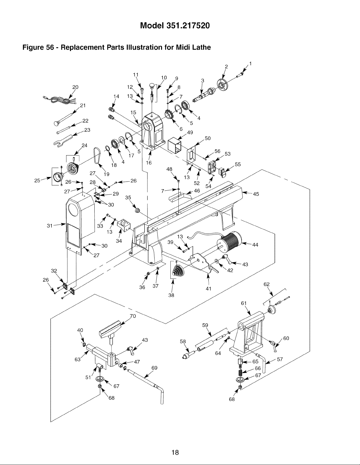
Model 351.217520
Figure 56 - Replacement Parts Illustration for Midi Lathe
20
11
12
14 13'x_
18
19
35
40
36 37 3!o_
59
43 58
64
60
51
69
68
18

KEY
NO. PART NO.
1 30929.00
2 30930.00
3 30931.00
4 STD315555
5 18121.00
6 30932.00
7 STD851005
8 STD852005
9 STD870516
10 30933.00
11 STD870635
12 STD851006
13 STD852006
14 30934.00
15 30935.00
16 N/A
17 16620.00
18 01900.00
19 30936.00
20 30937.00
21 30938.00
22 30939.00
23 30940.00
24 30941.00
25 30942.00
26 STD863410
27 STD851004
28 30943.00
29 30944.00
30 STD840407
31 30945.00
32 30946.00
33 STD863616
34 30947.00
35 30948.00
36 STD840812
37 STD851008
DESCRIPTION QTY.
Spur Center 1
Faceplate 1
Spindle 1
6005zz Ball Bearing* 2
3BMI-47 Retaining Ring 2
Index Ring 1
5mm Flat Washer* 2
5mm Lock Washer* 1
5-0.8 x 16mm Socket Head Bolt* 1
Index Pin Assembly 1
6-1.0 x 35mm Socket Head Bolt* 4
6mm Lock Washer* 4
6mm Flat Washer* 11
Strain Relief 2
Latch Post 1
Head Stock 1
47mm Wavy Washer 1
3AMI-25 Retaining Ring 1
Drive Belt 1
Line Cord 1
Center Removal Rod 1
Point Removal Tool 1
Wrench 1
Spindle Pulley w/Screw 1
Handwheel w/Screws 1
4-0.7 x 10mm Pan Head Screw* 11
4mm Flat Washer* 7
Latch 1
Bracket 1
4-0.7mm Hex Nut* 7
Head Stock Cover 1
Hinge 2
6-1.0 x 16mm Pan Head Screw* 2
Tool Holder 1
Grommet 1
8-1.25mm Hex Nut* 1
8mm Flat Washer* 1
* Standard hardware item available locally
A Not Shown
N/A Not available as replacement part
KEY
NO. PART NO.
38 30949.00
39 STD870616
40 00519.00
41 30950.00
42 30951.00
43 30952.00
44 30953.00
45 N/A
46 30954.00
47 30955.00
48 STD863516
49 30956.00
50 30957.00
51 30958.00
52 STD863610
53 30959.00
54 STD863412
55 30960.00
56 30961.00
57 30962.00
58 30963.00
59 30964.00
60 30965.00
61 N/A
62 30966.00
63 30972.00
64 00221.00
65 30967.00
66 30968.00
67 30969.00
68 STD843015
69 30970.00
70 30971.00
A 30973.00
A 30974.00
A 30897.00
DESCRIPTION QTY
Motor Pulley w/Set Screw 1
6-1.0 x 16mm Socket Head Bolt* 2
3AM1-12 Retaining Ring 2
Motor Mount Plate 1
Spacer 1
Locking Handle 2
Motor w/Cord 1
Bed 1
Chip Chute 1
Collar 1
5-0.8 x 16mm Pan Head Screw* 1
Switch Box 1
Headstock Plate 1
Threaded Sleeve 1
6-1.0 x 10mm Pan Head Screw* 3
Switch Guard 1
4-0.7 x 12mm Pan Head Screw* 4
Switch 1
Thread Forming Screw 2
Locking Lever 1
Live Center 1
Quill Assembly 1
Locking Handle 1
Tailstock 1
Handwheel Assembly 1
Tool Rest Base 1
3AMI-10 Retaining Ring 1
Threaded Shaft 1
Spring 1
Clamping Plate 2
10-1.5mm Fiber Hex Nut* 2
Locking Lever 1
Tool Rest 1
Motor Capacitor 1
Spur Center Point 1
Operator's Manual 1
m
RECOMMENDED ACCESSORIES FOR SPINDLE ml_z'_"_"_"_"_'jm
AND DRIVE ASSEMBLY
/
A 6 Piece Turning Tool Set 9-28596 I
Accessories available in catalog and on Sears.com.
19
TORNO MIDI
Modelo No.
351.217520
PRECAUClON: Lea este manual y siga las
Reglas de seguridad y las Instrucciones de
operaci6n, antes de usar este producto por
primera vez.
Ingles .............................................. 2-17
Ilustraci6n y Lista de Partes ............................ 18-19
Garantfa .............................................. 20
Reglas de Seguridad ................................. 20-21
Desempaque .......................................... 22
Montaje ............................................ 22-23
Instalaci6n .......................................... 23-25
Operaci6n .......................................... 25-35
Mantenimiento ......................................... 35
Identificaci6n de Problemas ............................ 38-39
GARANTIA COMPLETA DE UN ANO PARA
HERRAMIENTA CRAFTSMAN
Siesta herramienta Craftsman fallara por causa de defectos en
el material o en la mano de obra en un lapso de un aSo a partir
de la fecha de compra, LLAME al 1-800-4-MY-HOME® PARA
SOLICITAR LA REPARACION GRATUITA DEL PRODUCTO
(o su reemplazo si no se puede reparar la unidad).
Si esta herramienta se usa alguna vez para fines comerciales o
de alquiler, esta garantia es v_.lida tJnicamente por 90 dias a
partir de la fecha de compra.
Esta garantia le otorga derechos legales especificos y tambien
puede usted tener otros derechos que varien de estado a estado.
Sears, Roebuck and Co., Hoffman Estates, IL 60179
PRECAUCION: Siempre siga los procedimientos de operaci6n
correctos tal como se definen en este manual -- aun cuando
est6 familiarizado con el uso de esta o de otras herramientas
similares. Recuerde que un leve descuido puede ocasionar
lesiones personales graves.
ADVERTENClA: Por su propia seguridad, lea todas las normas
y precauciones antes de manejar la herramienta.
ADVERTENClA DE LA PROPOSlClON 65: Parte del polvo
producido por el lijado mec_.nico, serrado, esmerilado, taladrado
y otras tareas de construcci6n contiene sustancias quimicas que
el estado de California reconoce como cuasantes de cancer,
malformaciones congenitas u otros daSos reproductivos.
Algunos ejemplos de estas sustancias quimicas son:
• Plomo proveniente de pinturas con base de plomo.
• Silice cristalino proveniente de ladrillos, cemento y otro
material de mamposteria.
• Ars6nico y cromo proveniente de madera quimicamente tratada.
El riesgo debido a la exposici6n de estas sustancias quimicas
depende de la frecuencia con la cual realice este tipo de trabajo.
Para reducir la exposici6n a estas sustancias quimicas: trabaje
en un Area bien ventilada y utilice equipo de seguridad aprobado.
Cuando trabaje con este tipo de herramientas, utilice siempre
una m_.scara para la cara o respirador adecuadamente ajusta-
dos, aprobados por OSHA/NIOSH.
ESTE PREPARADO PARA EL TRABAJO
• Lleve puesta ropa adecuada. No use ropa suelta, guantes,
corbatas, anillos, pulseras, ni otras prendas que puedan
quedar atrapadas en las partes movibles de la m_.quina.
• Lleve puesta protecci6n para el cabello, para contener el
cabello largo.
• Lleve puestos zapatos de seguridad con suela antideslizante.
• Lleve puestas gafas de seguridad que cumplan con ANSI Z87.1
estadounidense. Las gafas de uso diario solamente tienen
lentes resistentes al impacto. NO son galas de seguridad.
• Lleve puesta una mascara para la cara o contra el polvo si
la operaci6n levanta mucho polvo.
• Est6 alerta y piense con claridad. Nunca opere las herramien-
tas mecgtnicas cuando est6 cansado(a), intoxicado(a) o cuan-
do est6 tomando medicamentos que producen somnolencia.
PREPARE EL AREA DONDE REALIZARA EL TRABAJO
• Mantenga el _trea de trabajo limpia. Las _.reas de trabajo
desordenadas inducen a accidentes.
• No utilice herramientas mec_.nicas en ambientes peligrosos.
Tampoco en lugares hQmedos o mojados. No las exponga
a la Iluvia.
• El Area de trabajo debe estar bien iluminada.
• Mantenga alas visitas a una distancia segura del Area de trabajo.
• Mantenga a los niSos fuera del lugar de trabajo. Disponga
el taller de manera que no presente ningQn peligro para los
niSos. Use candados, interruptores principales o remueva
las Ilaves del interruptor para impedir el uso involuntario
de la herramienta.
• Los cordones prolongadores no deben entrar en contacto
con objetos afilados, aceite, grasa, ni superficies calientes.
ES NECESARIO DAR SERVIClO A LAS HERRAMIENTAS
• Siempre desenchufe la herramienta antes de inspeccionarla.
• Consulte el manual para procedimientos de mantenimiento
y ajuste especificos.
• Mantenga la herramienta lubricada y limpia para una
operaci6n segura.
• Mantenga todas las partes listas para utilizar. Revise la
protecci6n u otras partes para determinar si operan correcta-
mente y pueden desempeSar la funci6n para la cual han
sido diseSadas.
• Revise si hay partes daSadas. Revise si las partes movibles
est_.n alineadas, si hay atascamiento, roturas, montajes y
cualquier otra condici6n que pueda afectar la operaci6n de
la herramienta.
• Cualquier protecci6n o parte daSada se debe cambiar o
reparar correctamente. No haga reparaciones provisorias.
(Use la lista de partes que se incluye para ordenar partes
de repuesto.)
• Nunca ajuste los accesorios cuando se encuentren funcio-
nando. Desconecte la energia electrica para evitar un
arranque accidental.
• Cambie inmediatamente los cordones prolongadores que
est6n da_ados o desgastados.
• Mantenga las herramientas de corte afiladas para Iograr
una operacidn eficiente y segura.
20
SEPA COMO USAR LA HERRAMIENTA
• Utilice la herramienta apropiada para el trabajo. No fuerce la
herramienta ni el accesorio a hacer un trabajo para el cual
no han sido diseSados.
• Desconecte la herramienta cuando cambie los accesorios.
• Evite arranques accidentales. AsegQrese que la herramienta
est6 en la posici6n OFF (apagado) antes de enchufarla, en-
cender la desconexi6n de seguridad o activar los interruptores.
• No fuerce la herramienta. Trabajar_. m_.s eficientemente a la
velocidad para la cual rue diseSada.
• Mantenga las manos alejadas del portaherramientas, las
puntas y otras partes movibles.
• Nunca deje la herramienta desatendida mientras est6 funcio-
nando. Apague la energia electrica y no abandone el _trea
hasta que la herramienta se haya detenido completamente.
• No trate de Ilegar m_.s all_. de donde puede alcanzar.
Mantenga el equilibrio y el balance correctos.
• Nunca se pare sobre la herramienta. Se pueden producir
lesiones graves si la herramienta se inclina o entra en con-
tacto con las puntas accidentalmente.
• Conozca su herramienta. Aprenda c6mo opera, su aplicaci6n
y sus limitaciones especificas.
• Maneje la pieza de trabajo de forma correcta. M6ntela firme-
mente en los dispositivos de sujeci6n. Proteja sus manos
contra posibles lesiones.
• Apague la m_.quina si la pieza de trabajo se parte o se suelta.
• Use las herramientas de corte tal como se recomienda en
"Operaci6n".
ADVERTENClA: Para su propia seguridad, no opere el torno
para madera hasta que est6 completamente montado e instalado
segQn las instrucciones.
PROTECCION: OJOS, MANOS, CARA, CUERPO Y OIDOS
• Si alguna parte del torno falta, funciona mal, se ha da_ado
o se ha roto, deje de operar la herramienta inmediatamente
hasta que la parte en cuesti6n sea reparada o reemplazada.
• Use orejeras o tapones para los oidos durante periodos de
operaci6n prolongados.
• Las astillas de madera sueltas u otros objetos que entren en
contacto con la pieza de trabajo giratoria pueden ser proyec-
tados a una velocidad muy alta. Esto se puede evitar si se
mantiene el torno limpio.
• Nunca encienda el torno antes de despejar todas las herra-
mientas, desperdicios de madera, etc. de la bancada, el ca-
bezal fijo y el cabezal m6vil, excepto por la pieza de trabajo y
los dispositivos de soporte que se utilizar_.n en la operaci6n.
• Nunca coloque la cara ni el cuerpo en linea con el portaherra-
mientas o la placa frontal.
• Nunca coloque sus dedos o sus manos en el trayecto de
las herramientas de corte.
• Nunca coloque sus manos en la parte posterior de la pieza
de trabajo para soportarla, remover los desperdicios de ma-
dera o por cualquier otra raz6n. Evite las operaciones poco
seguras o las posiciones incorrectas de las manos donde
un resbal6n repentino pueda hacer que sus dedos o manos
queden atrapados dentro de una pieza de trabajo giratoria.
• Apague el torno y desconecte la fuente de energia cuando
remueva la placa frontal, cambie las puntas, agregue o
remueva un dispositivo auxiliar, o cuando haga ajustes.
• Coloque el interruptor de cierre de Ilave en OFF (apagado) y
remueva la Ilave cuando no se est6 utilizando la herramienta.
21
• Si la pieza de trabajo se parte o se daSa en cualquier form&
apague el torno y remueva la pieza de trabajo de los sujeta-
dores. Deseche la pieza de trabajo daSada y empiece con
un pedazo de madera nuevo.
• Tenga cuidado especial cuando tornee madera que tiene veta
torcida o que est,. alabeada o arqueada -- puede cortarse
en forma dispareja o moverse excesivamente.
CONOZCA SUS HERRAMIENTAS DE CORTE
• Las herramientas de corte que est_.n desafiladas, gomosas,
mal afiladas o mal preparadas, pueden producir vibraci6n y
tintineo durante la operaci6n de corte. Minimice las lesiones
potenciales cuidando la herramienta correctamente y hacien-
do el mantenimiento regular de la m_.quina.
PIENSE EN LA SEGURIDAD
La seguridad es una combinaci6n del sentido com_n y la agu-
deza mental del operador cuando se est6 utilizando el torno.
• Para su propia seguridad, lea todas las reglas y precauciones
en el manual del operador antes de usar esta herramienta.
• Apriete todas las abrazaderas, los artefactos y la contrapunta
antes de aplicar energia electrica. AsegQrese que se hayan
removido todas las herramientas y Ilaves.
• Con el interruptor apagado, rote la pieza de trabajo manual-
mente para asegurarse que exista un espacio libre adecuado.
Haga arrancar la m_.quina a la velocidad m_.s baja para
verificar que la herramienta est6 segura.
• En el caso de las piezas grandes, cree una pieza no termina-
da en otro equipo antes de instalarla en la placa frontal.
• No monte ninguna pieza de trabajo que tenga partiduras
o nudos.
• Nunca trate de volver a montar un torneado de placa frontal
en la placa frontal por ninguna raz6n.
• Nunca trate de volver a montar un torneado entre puntas
si se han removido o alterado las puntas originales en el
torneado.
• Cuando vuelva a montar un torneado entre puntas, donde
las puntas originales no han sido alteradas, asegQrese que
la velocidad est6 ajustada al nivel m_.s bajo para el arranque.
• Tenga cuidado especial cuando monte un torneado entre
puntas en la placa frontal o un torneado de placa frontal
entre puntas para operaciones secundarias. AsegQrese que
la velocidad est6 ajustada al nivel m_.s bajo para el arranque.
• Nunca Ileve a cabo una operaci6n con este torno cuando
est6 sosteniendo la pieza de trabajo con la mano. No monte
escariadores, fresas, brocas, ruedas con rayos de alambre
o ruedas pulidoras en el husillo del cabezal fijo.
• Cuando lije manualmente piezas de trabajo montadas en la
placa frontal o entre puntas, complete el lijado ANTES de
removerlas del torno.
• Nunca haga funcionar el husillo en direcci6n equivocada. La
herramienta de corte puede salirse de sus manos. La pieza
de trabajo siempre debe girar en direcci6n del operador.
• En el caso de torneado de husillo, SIEMPRE coloque el
soporte de la herramienta sobre la linea del centro de la
pieza de trabajo y del husillo (aproximadamente 1/8").
• Use un accesorio del portabrocas en el cabezal m6vil
solamente. No monte ninguna broca que sobrepase las
mordazas del portaherramientas m_.s de 6".
PREOAUOION: Siga las instrucciones de seguridad que
aparecen en el guardacorrea de su torno.
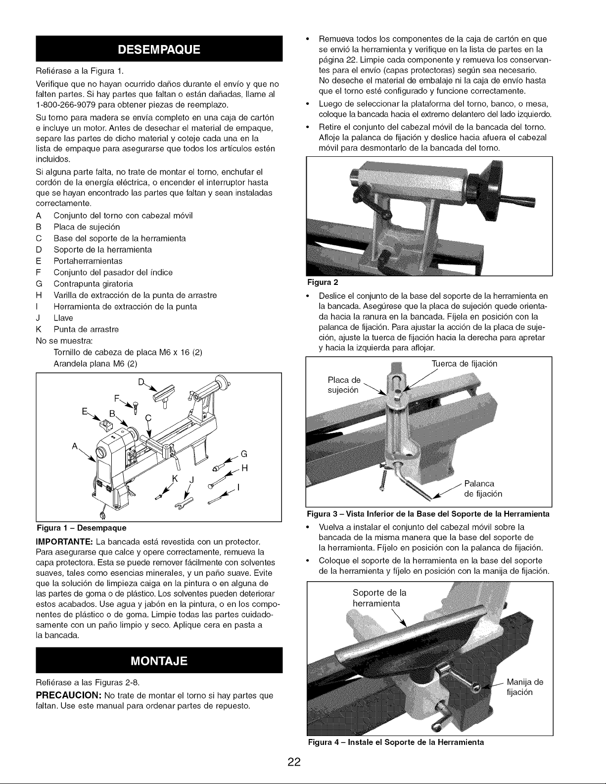
RefierasealaFigura1.
VerifiquequenohayanocurridodaSosduranteelenvioyqueno
faltenpartes.Sihaypartesquefaltanoest_.ndaSadas,Ilameal
1-800-266-9079paraobtenerpiezasdereemplazo.
Sutornoparamaderaseenviacompletoenunacajadecartdn
eincluyeunmotor.Antesdedesecharelmaterialdeempaque,
separelaspartesdedichomaterialycotejecadaunaenla
listadeempaqueparaasegurarsequetodoslosarticulosest6n
incluidos.
Sialgunapartefalta,notratedemontareltorno,enchufarel
corddndelaenergiaelectrica,oencenderelinterruptorhasta
quesehayanencontradolaspartesquefaltanyseaninstaladas
correctamente.
A Conjuntodeltornoconcabezalmdvil
B Placadesujecidn
C Basedelsoportedelaherramienta
D Soportedelaherramienta
E Portaherramientas
F Conjuntodelpasadordelindice
G Contrapuntagiratoria
H Varilladeextraccidndelapuntadearrastre
I Herramientadeextraccidndelapunta
J Llave
K Puntadearrastre
Nosemuestra:
TornillodecabezadeplacaM6x16(2)
ArandelaplanaM6(2)
F...._
E_ B _
A
Figura 1 - Desempaque
IMPORTANTE: La bancada est,. revestida con un protector.
Para asegurarse que calce y opere correctamente, remueva la
capa protectora. Esta se puede remover f_.cilmente con solventes
suaves, tales como esencias minerales, y un paso suave. Evite
que la soluci6n de limpieza caiga en la pintura o en alguna de
las partes de goma o de pl_.stico. Los solventes pueden deteriorar
estos acabados. Use agua y jab6n en la pintura, o en los compo-
nentes de pl_.stico o de goma. Limpie todas las partes cuidado-
samente con un paso limpio y seco. Aplique cera en pasta a
la bancada.
• Remueva todos los componentes de la caja de cartdn en que
se envi6 la herramienta y verifique en la lista de partes en la
p_.gina 22. Limpie cada componente y remueva los conservan-
tes para el envio (capas protectoras) segL_n sea necesario.
No deseche el material de embalaje ni la caja de envio hasta
que el torno est6 configurado y funcione correctamente.
• Luego de seleccionar la plataforma del torno, banco, o mesa,
coloque la bancada hacia el extremo delantero del lado izquierdo.
• Retire el conjunto del cabezal mdvil de la bancada del torno.
Afloje la palanca de fijacidn y deslice hacia afuera el cabezal
mdvil para desmontarlo de la bancada del torno.
Figura 2
• Deslice el conjunto de la base del soporte de la herramienta en
la bancada. AsegL_rese que la placa de sujeci6n quede orienta-
da hacia la ranura en la bancada. Fijela en posici6n con la
palanca de fijaci6n. Para ajustar la acci6n de la placa de suje-
ci6n, ajuste la tuerca de fijaci6n hacia la derecha para apretar
y hacia la izquierda para aflojar.
Tuerca de fijaci6n
Placa de
sujeci6n
Palanca
de fijaci6n
Figura 3 - Vista Inferior de la Base del Soporte de la Herramienta
• Vuelva a instalar el conjunto del cabezal m6vil sobre la
bancada de la misma manera que la base del soporte de
la herramienta. Fijelo en posici6n con la palanca de fijaci6n.
• Coloque el soporte de la herramienta en la base del soporte
de la herramienta y fijelo en posici6n con la manija de fijaci6n.
Soporte de la
herramienta
Refierase a las Figuras 2-8.
PRECAUCION: No trate de montar el torno si hay partes que
faltan. Use este manual para ordenar partes de repuesto.
Manija de
fijaci6n
Figura 4 - Instale el Soporte de la Herramienta
22
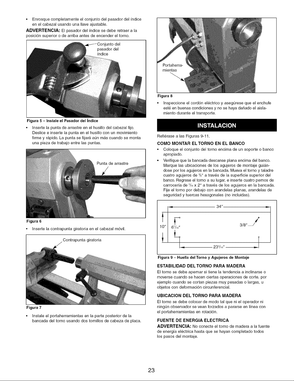
• Enrosque completamente el conjunto del pasador del indice
en el cabezal usando una Ilave ajustable.
ADVERTENOIA: El pasador del indice se debe retraer a la
posicidn superior o de arriba antes de encender el torno.
I unto del
Figura 5 - Instale el Pasador del |ndice
• Inserte la punta de arrastre en el husillo del cabezal fijo.
Deslice e inserte la punta en el husillo con un movimiento
firme y r_.pido. La punta se fijar_, aQn m_.s cuando se monta
una pieza de trabajo entre las puntas.
Punta de arrastre
Figura 6
• Inserte la contrapunta giratoria en el cabezal m6vil.
Contrapunta giratoria
Figura 7
• Instale el portaherramientas en la parte posterior de la
bancada del torno usando dos tornillos de cabeza de placa.
mientas
Figura 8
• Inspeccione el cord6n electrico y asegQrese que el enchufe
est6 en buenas condiciones y no se haya daSado el aisla-
miento durante el transporte.
Refierase alas Figuras 9-11.
COMO MONTAR ELTORNO EN EL BANCO
• Coloque el conjunto del torno encima de un soporte o banco
apropiado.
• Verifique que la bancada descanse plana encima del banco.
Marque las ubicaciones de los agujeros de montaje gui_.n-
close por los agujeros en la bancada. Mueva el torno y taladre
cuatro agujeros de 3/8"a trav6s de la superficie superior del
banco. Regrese el torno a su lugar, e inserte cuatro pernos de
carroceria de s/16x 2" a trav6s de los agujeros en la bancada.
Fije el torno por debajo con arandelas planas, arandelas de
seguridad y tuercas hexagonales (no incluidas).
Figura 9 - Huella del Torno y Agujeros de Montaje
ESTABILIDAD DEL TORNO PARA MADERA
El torno se debe apernar si tiene la tendencia a inclinarse o
moverse cuando se hacen ciertas operaciones de corte, por
ejemplo cuando se cortan piezas muy pesadas o largas, u
objetos con deformaci6n circunferencial.
UBICACION DEL TORNO PARA MADERA
El torno se debe colocar de modo tal que ni el operador ni
ningQn observador se vean forzados a pararse en linea con
el portaherramientas en rotaci6n.
FUENTE DE ENERGIA ELECTRICA
ADVERTENCIA: No conecte el torno de madera a la fuente
de energia electrica hasta que se hayan completado todos
los pasos del montaje.
23

El motor ha sido diseSado para operar con el voltaje y la frecuen-
cia especificados. Las cargas normales ser_.n manejadas en
forma segura con voltajes que no varian m_.s de 10% sobre o
bajo el voltaje especificado. Si las unidades se hacen funcionar
con voltajes que no se encuentran dentro de la clasificacidn, se
pueden sobrecalentar y se puede quemar el motor. Las cargas
pesadas exigen que el voltaje en los terminales del motor no sea
menor que el voltaje especificado en la placa de identificacidn.
• La fuente de alimentacidn del motor est,. controlada por un
interruptor oscilante enclavado unipolar. Extraiga la Ilave
para impedir el uso no autorizado de la herramienta.
INSTRUCCIONES PARA LA CONEXION A TIERRA
ADVERTENCIA: Las conexiones incorrectas del conductor de
conexi6n a tierra del equipo pueden producir un riesgo de sacu-
dida electrica. Mientras el equipo est6 en funcionamiento, de-
ber_. mantenerse conectado a tierra para proteger al operador
contra una sacudida electrica.
• Consulte con un electricista calificado si no entiende las
instrucciones para la conexi6n a tierra o si tiene alguna duda
si la herramienta est,. conectada a tierra correctamente.
• La herramienta est,. equipada con un cord6n de 3 conduc-
tores aprobado, con una capacidad de 150 V y con un en-
chufe tipo conexi6n a tierra de tres puntas (vea la Figura 10),
para proteger al usuario contra los peligros de sacudidas
electricas.
• El enchufe de conexi6n a tierra debe enchufarse directamente
en un recept_tculo tipo conexi6n a tierra de 3 puntas, instala-
do correctamente y conectado a tierra, tal como se muestra
(Figura 10).
Tomacorriente conectado_l 1
a tierra correctamente
Punta de conexi6n a tierra
Enchufe de tres puntas
Figura 10 - Recept_culo de 3 Puntas
• No remueva ni altere la punta de conexi6n a tierra de manera
alguna. De producirse un fallo o una averia, la conexi6n a
tierra ofrece el circuito con la menor resistencia para la
sacudida electrica.
ADVERTENOIA: Evite que sus dedos entrenen contacto con
los terminales del enchufe cuando Io instale o Io remueva del
tomacorriente.
• El enchufe debe ser conectado en un tomacorriente que le
corresponda, que est6 instalado y conectado a tierra correc-
tamente segQn los c6digos y las regulaciones locales. No
modifique el enchufe proporcionado. Si no calza en el toma-
corriente, haga que un electricista calificado instale el toma-
corriente correcto.
• Peri6dicamente inspeccione los cordones de la herramienta
y si est_.n daSados Ilevelos a un lugar de servicio autorizado
para su reparaci6n.
• El conductor verde (o verde y amarillo) en el cord6n, es el
cable de conexi6n a tierra. De ser necesario reparar o cam-
biar el cord6n prolongador o el enchufe, no conecte el cable
verde (o verde y amarillo) a un terminal cargado.
• En los lugares donde hay recept_.culos de 2 puntas en la
pared, se debe cambiar por uno de 3 puntas, conectado a
tierra correctamente e instalado segQn el C6digo Nacional
de Electricidad y segQn los c6digos o regulaciones locales.
ADVERTENOIA: Un electricista calificado debe realizar
este trabajo.
Un adaptador provisorio de 3 puntas a 2 puntas (vea la Figura
11) se encuentra disponible para conectar los enchufes a un
tomacorriente bipolar en el caso de que este estuviera conectado
a tierra correctamente.
• No use un adaptador de 3 puntas a 2 puntas a menos que
Io permitan los c6digos y regulaciones locales y nacionales.
• (En Canada no se permite usar un adaptador de conexi6n
a tierra de 3 puntas a 2 puntas.) En donde sea permitido,
la orejeta rigida verde o el terminal en el lado del adaptador
deben conectarse a una conexi6n a tierra permanente en
forma segura, tal como una tuberia de agua, una caja de sali-
da o un sistema de cables conectados a tierra correctamente.
• Muchos de los tornillos de las placas de cubierta, tuberias de
agua y cajas de salida no est_.n conectados a tierra correcta-
mente. Para asegurarse que habr_, una conexi6n a tierra
correcta, un electricista calificado deber_, probar los medios
de conexi6n a tierra.
LengQeta de conexi6n a tierra
AsegQrese que
Adaptador est6 conectado a
una conexi6n a
Enchufe de \\ ([ II_ II tierra conocida
3 pu Recept_.culo
de 2 puntas
Figura 11 - Recept_culo de 2 Puntas con Adaptador
CORDONES PROLONGADORES
• El uso de un cord6n prolongador produce una caida en el
voltaje y p6rdida de energia electrica.
• Los cables de los cordones prolongadores deben ser del
tamaSo suficiente para Ilevar la corriente y mantener un
voltaje adecuado.
• Use la tabla para determinar el tamaSo minimo de los cables
del cord6n prolongador (A.W.G).
• Use s61o cordones prolongadores de 3 cables que contengan
enchufes de conexi6n a tierra de 3 puntas, y recept_tculos
tripolares que se adapten al enchufe de la herramienta.
• Si el cord6n prolongador est,. desgastado, cortado o da_ado
en alguna forma, c_.mbielo inmediatamente.
Longitud del cord6n prolongador
TamaSo del cable A.W.G
Hasta 50 pies ....................................... 16
AVlSO: No se recomienda el uso de cordones prolongadores
de una Iongitud mayor a 50 pies.
EL MOTOR
El torno de madera viene con el motor y el cableado instalados.
Caballos de fuerza (Servicio continuo) .................. 1/2
Voltaje (C.C.) ...................................... 120
Amperios ........................................... 6
Hertz ............................................. 60
Fase ....................................... Monof_.sico
RPM ............................................ 3450
CONEXlONES ELECTRICAS
ADVERTENClA: AsegLirese que la unidad est6 apagada
y desconectada de la fuente de energia electrica antes de
inspeccionar cualquier cableado.
El torno viene precableado para uso con una fuente de ali-
mentaci6n de 120 voltios, 60 Hz. El abastecimiento de energia
electrica que se usa en el motor est,. controlado por un interrup-
tor oscilante de enclavamiento, unipolar.
24
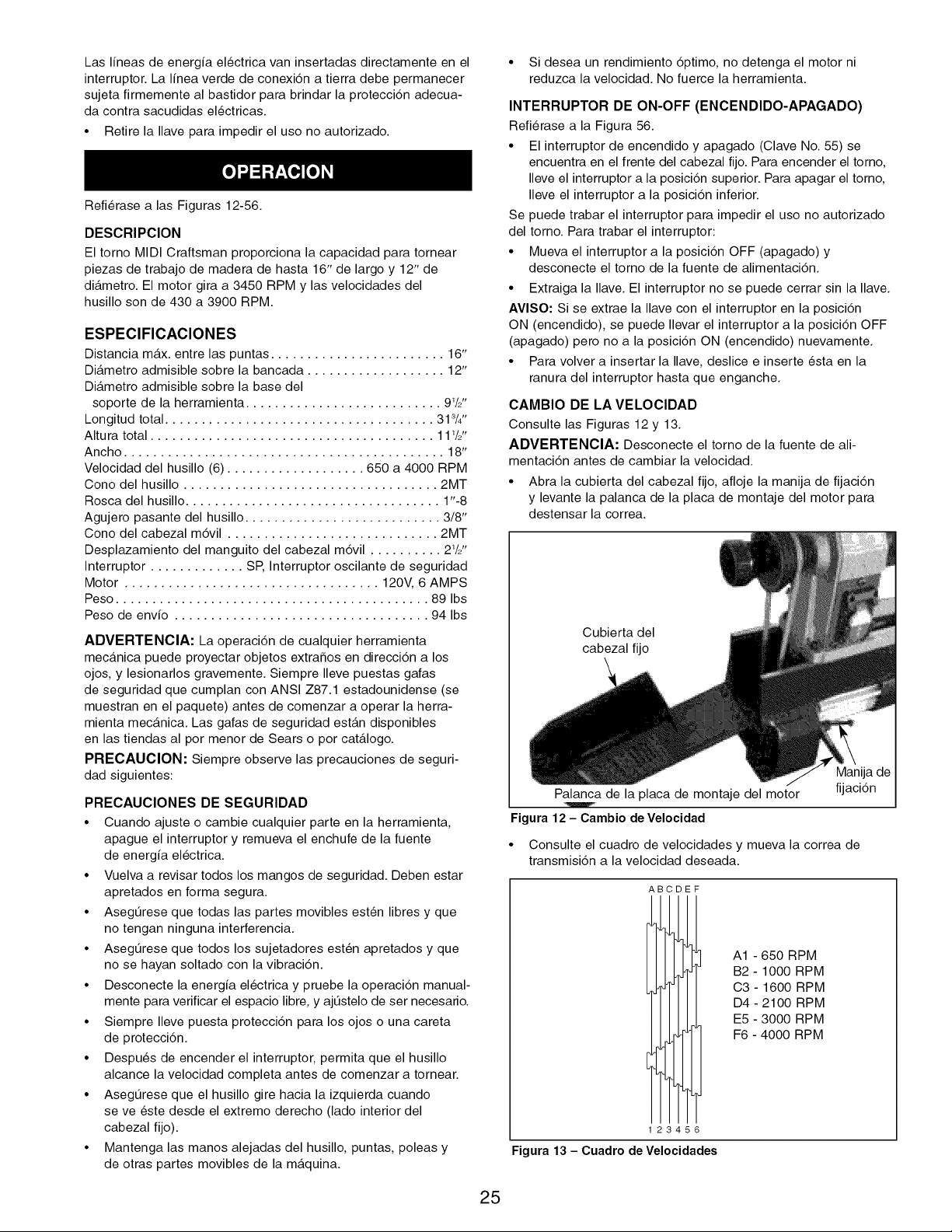
Las Ifneas de energfa electrica van insertadas directamente en el
interruptor. La Ifnea verde de conexidn a tierra debe permanecer
sujeta firmemente al bastidor para brindar la proteccidn adecua-
da contra sacudidas electricas.
• Retire la Ilave para impedir el uso no autorizado.
Refierase alas Figuras 12-56.
DESCRIPCION
El torno MIDI Craftsman proporciona la capacidad para tornear
piezas de trabajo de madera de hasta 16" de largo y 12" de
di_.metro. El motor gira a 3450 RPM y las velocidades del
husillo son de 430 a 3900 RPM.
ESPECIFICACIONES
Distancia m_.x. entre las puntas ........................ 16"
Di_.metro admisible sobre la bancada ................... 12"
Di_.metro admisible sobre la base del
soporte de la herramienta ........................... 91/2"
Longitud total ..................................... 313/4"
Altura total ....................................... 111/2"
Ancho ............................................ 18"
Velocidad del husillo (6) ................... 650 a 4000 RPM
Cono del husillo ................................... 2MT
Rosca del husillo ................................... 1"-8
Agujero pasante del husillo ........................... 3/8"
Cono del cabezal m6vil ............................. 2MT
Desplazamiento del manguito del cabezal m6vil .......... 2W'
Interruptor ............. SP, Interruptor oscilante de seguridad
Motor ................................... 120V, 6 AMPS
Peso ........................................... 89 Ibs
Peso de envfo ................................... 94 Ibs
ADVERTENClA: La operaci6n de cualquier herramienta
mec_.nica puede proyectar objetos extraSos en direcci6n a los
ojos, y lesionarlos gravemente. Siempre Ileve puestas gafas
de seguridad que cumplan con ANSI Z87.1 estadounidense (se
muestran en el paquete) antes de comenzar a operar la herra-
mienta mec_.nica. Las gafas de seguridad est_.n disponibles
en las tiendas al por menor de Sears o por cat_.logo.
PREOAUOION: Siempre observe las precauciones de seguri-
dad siguientes:
PRECAUClONES DE SEGURIDAD
• Cuando ajuste o cambie cualquier parte en la herramienta,
apague el interruptor y remueva el enchufe de la fuente
de energfa electrica.
• Vuelva a revisar todos los mangos de seguridad. Deben estar
apretados en forma segura.
• AsegQrese que todas las partes movibles est6n libres y que
no tengan ninguna interferencia.
• AsegQrese que todos los sujetadores est6n apretados y que
no se hayan soltado con la vibraci6n.
• Desconecte la energfa electrica y pruebe la operaci6n manual-
mente para verificar el espacio libre, y ajQstelo de ser necesario.
• Siempre Ileve puesta protecci6n para los ojos o una careta
de protecci6n.
• Despues de encender el interruptor, permita que el husillo
alcance la velocidad completa antes de comenzar a tornear.
• AsegQrese que el husillo gire hacia la izquierda cuando
se ve este desde el extremo derecho (lado interior del
cabezal fijo).
• Mantenga las manos alejadas del husillo, puntas, poleas y
de otras partes movibles de la m_.quina.
25
• Si desea un rendimiento 6ptimo, no detenga el motor ni
reduzca la velocidad. No fuerce la herramienta.
INTERRUPTOR DE ON-OFF (ENCENDIDO-APAGADO)
Refierase a la Figura 56.
• El interruptor de encendido y apagado (Clave No. 55) se
encuentra en el frente del cabezal fijo. Para encender el torno,
Ileve el interruptor a la posici6n superior. Para apagar el torno,
Ileve el interruptor a la posici6n inferior.
Se puede trabar el interruptor para impedir el uso no autorizado
del torno. Para trabar el interruptor:
• Mueva el interruptor a la posici6n OFF (apagado) y
desconecte el torno de la fuente de alimentaci6n.
• Extraiga la Ilave. El interruptor no se puede cerrar sin la Ilave.
AVlSO: Si se extrae la Ilave con el interruptor en la posici6n
ON (encendido), se puede Ilevar el interruptor a la posici6n OFF
(apagado) pero no a la posici6n ON (encendido) nuevamente.
• Para volver a insertar la Ilave, deslice e inserte esta en la
ranura del interruptor hasta que enganche.
CAMBIO DE LA VELOCIDAD
Consulte las Figuras 12 y 13.
ADVERTENClA: Desconecte el torno de la fuente de ali-
mentaci6n antes de cambiar la velocidad.
• Abra la cubierta del cabezal fijo, afloje la manija de fijaci6n
y levante la palanca de la placa de montaje del motor para
destensar la correa.
Cubierta del
cabezal fijo
Figura 12- Cambio de Velocidad
• Consulte el cuadro de velocidades y mueva la correa de
transmisi6n a la velocidad deseada.
AB DEF
2 6
Figura 13 - Cuadro de Velocidades
A1 - 650 RPM
B2 - 1000 RPM
C3 - 1600 RPM
D4- 2100 RPM
E5 - 3000 RPM
F6 - 4000 RPM
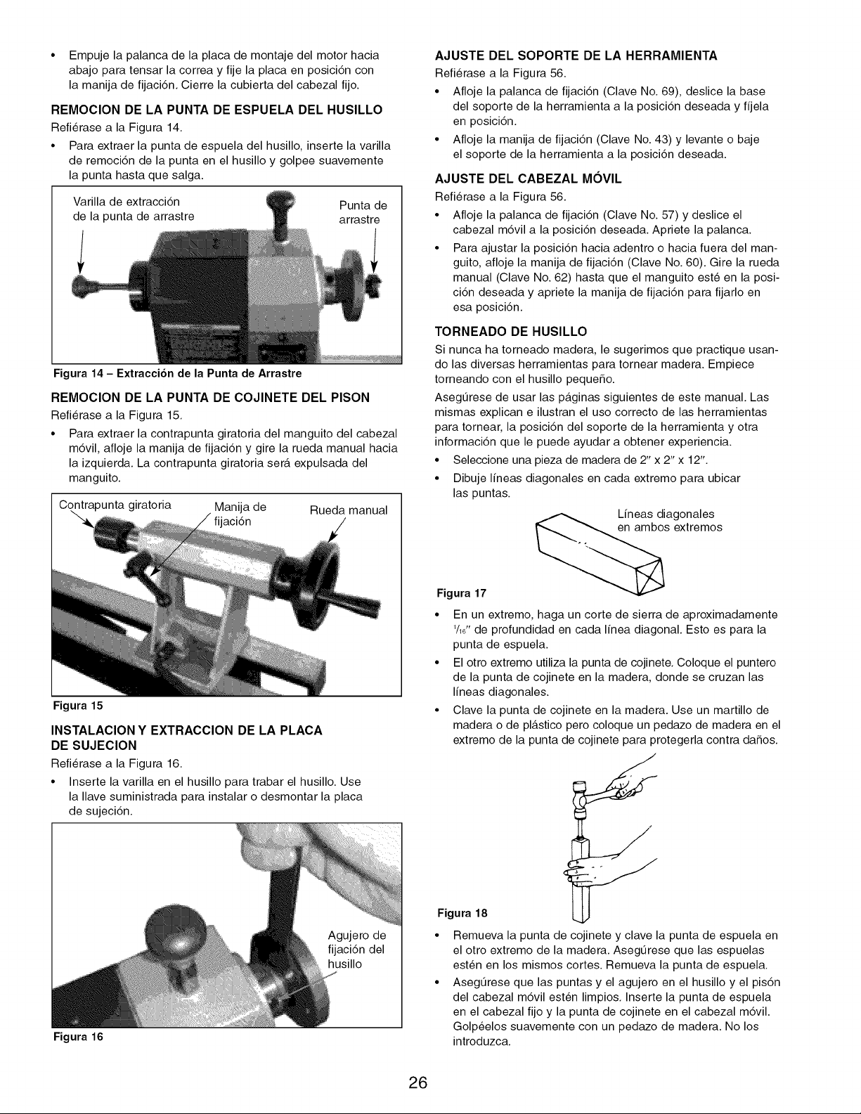
• Empujelapalancadelaplacademontajedelmotorhacia
abajoparatensarlacorreayfijelaplacaenposici6ncon
lamanijadefijaci6n.Cierrelacubiertadelcabezalfijo.
REMOCION DE LA PUNTA DE ESPUELA DEL HUSILLO
Refierase a la Figura 14.
• Para extraer la punta de espuela del husillo, inserte la varilla
de remoci6n de la punta en el husillo y golpee suavemente
la punta hasta que salga.
Varilla de extracci6n
de la punta de arrastre
Punta de
arrastre
Figura 14 - Extraccibn de la Punta de Arrastre
REMOCION DE LA PUNTA DE COJINETE DEL PISON
Refierase a la Figura 15.
• Para extraer la contrapunta giratoria del manguito del cabezal
m6vil, afloje la manija de fijaci6n y gire la rueda manual hacia
la izquierda. La contrapunta giratoria ser_. expulsada del
manguito.
intrapunta giratoria Manija de Rueda manual
aci6n
Figura 15
INSTALACION Y EXTRACCION DE LA PLACA
DE SUJECION
Refierase a la Figura 16.
• Inserte la varilla en el husillo para trabar el husillo. Use
la Ilave suministrada para instalar o desmontar la placa
de sujeci6n.
Figura 16
AJUSTE DEL SOPORTE DE LA HERRAMIENTA
Refierase a la Figura 56.
• Afloje la palanca de fijaci6n (Clave No. 69), deslice la base
del soporte de la herramienta a la posici6n deseada y fijela
en posici6n.
• Afloje la manija de fijaci6n (Clave No. 43) y levante o baje
el soporte de la herramienta a la posici6n deseada.
AJUSTE DEL CABEZAL MOVIL
Refierase a la Figura 56.
• Afloje la palanca de fijaci6n (Clave No. 57) y deslice el
cabezal m6vil a la posici6n deseada. Apriete la palanca.
• Para ajustar la posici6n hacia adentro o hacia fuera del man-
guito, afloje la manija de fijaci6n (Clave No. 60). Gire la rueda
manual (Clave No. 62) hasta que el manguito est6 en la posi-
ci6n deseada y apriete la manija de fijaci6n para fijarlo en
esa posici6n.
Figura 17
TORNEADO DE HUSILLO
Si nunca ha torneado madera, le sugerimos que practique usan-
do las diversas herramientas para tornear madera. Empiece
torneando con el husillo pequeSo.
AsegQrese de usar las p_tginas siguientes de este manual. Las
mismas explican e ilustran el uso correcto de las herramientas
para tornear, la posici6n del soporte de la herramienta y otra
informaci6n que le puede ayudar a obtener experiencia.
• Seleccione una pieza de madera de 2" x 2" x 12".
• Dibuje lineas diagonales en cada extremo para ubicar
las puntas.
Lineas diagonales
extremos
• En un extremo, haga un corte de sierra de aproximadamente
1/1_"de profundidad en cada linea diagonal. Esto es para la
punta de espuela.
• El otro extremo utiliza la punta de cojinete. Coloque el puntero
de la punta de cojinete en la madera, donde se cruzan las
lineas diagonales.
• Clave la punta de cojinete en la madera. Use un martillo de
madera o de pl_.stico pero coloque un pedazo de madera en el
extremo de la punta de cojinete para protegerla contra daSos.
Figura 18
• Remueva la punta de cojinete y clave la punta de espuela en
el otro extremo de la madera. AsegQrese que las espuelas
est6n en los mismos cortes. Remueva la punta de espuela.
• AsegQrese que las puntas y el agujero en el husillo y el pis6n
del cabezal m6vil est6n limpios. Inserte la punta de espuela
en el cabezal fijo y la punta de cojinete en el cabezal m6vil.
Golp6elos suavemente con un pedazo de madera. No los
introduzca.
26
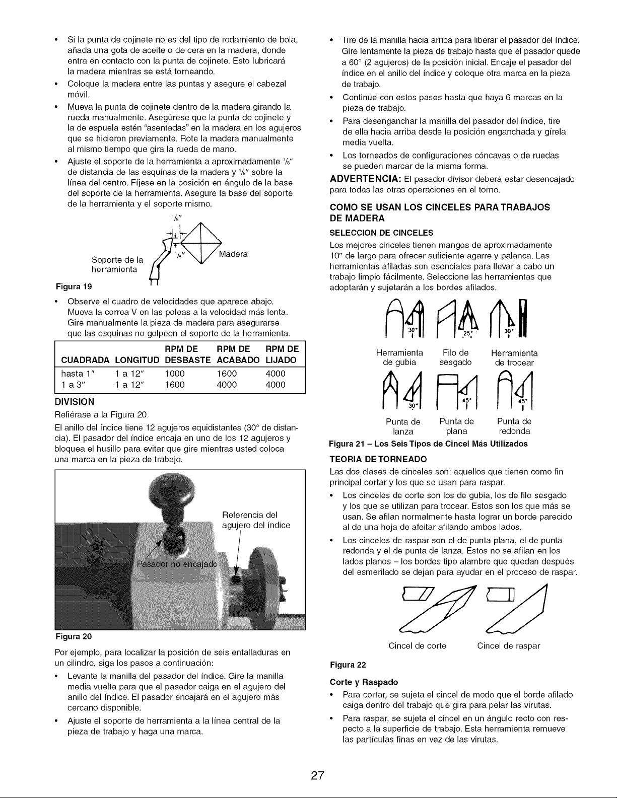
• Si la punta de cojinete no es del tipo de rodamiento de bola,
aSada una gota de aceite o de cera en la madera, donde
entra en contacto con la punta de cojinete. Esto lubricar_.
la madera mientras se est,. torneando.
• Coloque la madera entre las puntas y asegure el cabezal
mdvil.
• Mueva la punta de cojinete dentro de la madera girando la
rueda manualmente. AsegQrese que la punta de cojinete y
la de espuela est6n "asentadas" en la madera en los agujeros
que se hicieron previamente. Rote la madera manualmente
al mismo tiempo que gira la rueda de mano.
• Ajuste el soporte de la herramienta a aproximadamente 1/8"
de distancia de las esquinas de la madera y 1/8"sobre la
linea del centro. Fijese en la posicidn en _.ngulo de la base
del soporte de la herramienta. Asegure la base del soporte
de la herramienta y el soporte mismo.
1/8r_
herramientaS°p°rtede la _ 1/,, "x_ Madera
Figura 19
Observe el cuadro de velocidades que aparece abajo.
Mueva la correa V en las poleas a la velocidad m_.s lenta.
Gire manualmente la pieza de madera para asegurarse
que las esquinas no golpeen el soporte de la herramienta.
RPM DE RPM DE RPM DE
CUADRADA LONGITUD DESBASTE ACABADO LIJADO
hasta 1" 1 a 12" 1000 1600 4000
1 a 3" 1 a 12" 1600 4000 4000
DIVISION
Refierase a la Figura 20.
El anillo del indice tiene 12 agujeros equidistantes (30 ° de distan-
cia). El pasador del indice encaja en uno de los 12 agujeros y
bloquea el husillo para evitar que gire mientras usted coloca
una marca en la pieza de trabajo.
Referencia del
agujero del indice
Figura 20
Por ejemplo, para Iocalizar la posici6n de seis entalladuras en
un cilindro, siga los pasos a continuaci6n:
• Levante la manilla del pasador del indice. Gire la manilla
media vuelta para que el pasador caiga en el agujero del
anillo del indice. El pasador encajar_, en el agujero m_.s
cercano disponible.
• Ajuste el soporte de herramienta a la linea central de la
pieza de trabajo y haga una marca.
• Tire de la manilla hacia arriba para liberar el pasador del indice.
Gire lentamente la pieza de trabajo hasta que el pasador quede
a 60 ° (2 agujeros) de la posici6n inicial. Encaje el pasador del
indice en el anillo del indice y coloque otra marca en la pieza
de trabajo.
• ContinQe con estos pases hasta que haya 6 marcas en la
pieza de trabajo.
• Para desenganchar la manilla del pasador del indice, tire
de ella hacia arriba desde la posici6n enganchada y girela
media vuelta.
• Los torneados de configuraciones c6ncavas o de ruedas
se pueden marcar de la misma forma.
ADVERTENCIA: El pasador divisor deber_, estar desencajado
para todas las otras operaciones en el torno.
COMO SE USAN LOS CINCELES PARA TRABAJOS
DE MADERA
SELECClON DE ClNCELES
Los mejores cinceles tienen mangos de aproximadamente
10" de largo para ofrecer suficiente agarre y palanca. Las
herramientas afiladas son esenciales para Ilevar a cabo un
trabajo limpio f_.cilmente. Seleccione las herramientas que
adoptar_.n y sujetar_.n a los bordes afilados.
Herramienta Filo de Herramienta
de gubia sesgado de trocear
Punta de Punta de Punta de
lanza plana redonda
Figura 21 - Los Seis Tipos de Cincel M_is Utilizados
TEORIA DE TORNEADO
Las dos clases de cinceles son: aquellos que tienen como fin
principal cortar y los que se usan para raspar.
• Los cinceles de corte son los de gubia, los de filo sesgado
y los que se utilizan para trocear. Estos son los que m_ts se
usan. Se afilan normalmente hasta Iograr un borde parecido
al de una hoja de afeitar afilando ambos lados.
• Los cinceles de raspar son el de punta plana, el de punta
redonda y el de punta de lanza. Estos no se afilan en los
lados pianos - los bordes tipo alambre que quedan despues
del esmerilado se dejan para ayudar en el proceso de raspar.
Cincel de corte Cincel de raspar
Figura 22
Corte y Raspado
• Para cortar, se sujeta el cincel de modo que el borde afilado
caiga dentro del trabajo que gira para pelar las virutas.
• Para raspar, se sujeta el cincel en un _.ngulo recto con res-
pecto a la superficie de trabajo. Esta herramienta remueve
las particulas finas en vez de las virutas.
27
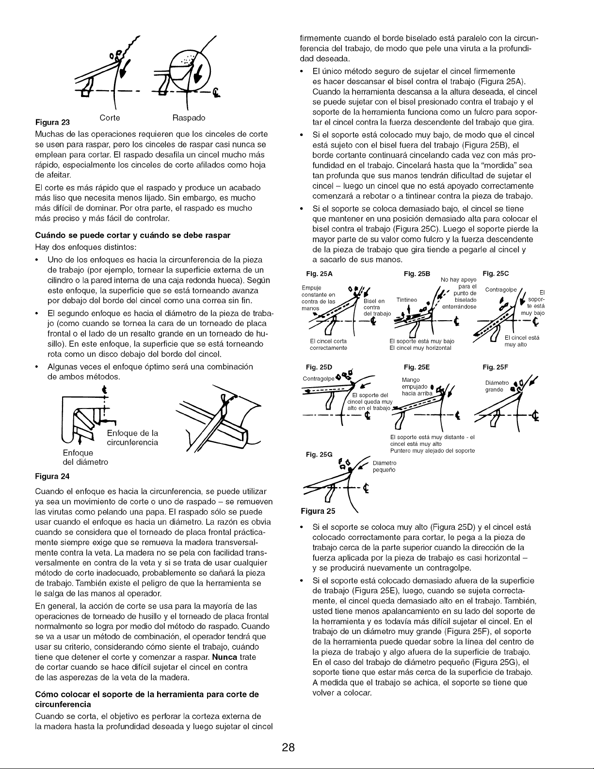
Corte
Figura 23
Ras 3ado
Muchas de las operaciones requieren que los cinceles de corte
se usen para raspar, pero los cinceles de raspar casi nunca se
emplean para cortar. El raspado desafila un cincel mucho m_.s
r_.pido, especialmente los cinceles de corte afilados como hoja
de afeitar.
El corte es m_.s r_.pido que el raspado y produce un acabado
m_.s liso que necesita menos lijado. Sin embargo, es mucho
m_.s dificil de dominar. Por otra parte, el raspado es mucho
m_.s preciso y m_.s f_.cil de controlar.
Cu_ndo se puede cortar y cu_ndo se debe raspar
Hay dos enfoques distintos:
• Uno de los enfoques es hacia la circunferencia de la pieza
de trabajo (por ejemplo, tornear la superficie externa de un
cilindro o la pared interna de una caja redonda hueca). SegQn
este enfoque, la superficie que se est,. torneando avanza
por debajo del borde del cincel como una correa sin fin.
El segundo enfoque es hacia el di_.metro de la pieza de traba-
jo (como cuando se tornea la cara de un torneado de placa
frontal o el lado de un resalto grande en un torneado de hu-
sillo). En este enfoque, la superficie que se est,. torneando
rota como un disco debajo del borde del cincel.
Algunas veces el enfoque 6ptimo ser_. una combinacidn
de ambos metodos.
!
foque de la
t _ circunferencia
Enfoque
del di_.metro
Figura 24
Cuando el enfoque es hacia la circunferencia, se puede utilizar
ya sea un movimiento de corte o uno de raspado - se remueven
las virutas como pelando una papa. El raspado s61o se puede
usar cuando el enfoque es hacia un di_.metro. La raz6n es obvia
cuando se considera que el torneado de placa frontal pr_.ctica-
mente siempre exige que se remueva la madera transversal-
mente contra la veta. La madera no se pela con facilidad trans-
versalmente en contra de la veta y si se trata de usar cualquier
metodo de corte inadecuado, probablemente se daSar_, la pieza
de trabajo. Tambien existe el peligro de que la herramienta se
le salga de las manos al operador.
En general, la acci6n de corte se usa para la mayoria de las
operaciones de torneado de husillo y el torneado de placa frontal
normalmente se Iogra por medio del metodo de raspado. Cuando
se va a usar un metodo de combinaci6n, el operador tendr_, que
usar su criterio, considerando c6mo siente el trabajo, cu_.ndo
tiene que detener el corte y comenzar a raspar. Nunca trate
de cortar cuando se hace dificil sujetar el cincel en contra
de las asperezas de la veta de la madera.
C6mo colocar el soporte de la herramienta para corte de
circunferencia
Cuando se corta, el objetivo es perforar la corteza externa de
la madera hasta la profundidad deseada y luego sujetar el cincel
firmemente cuando el borde biselado est,. paralelo con la circun-
ferencia del trabajo, de modo que pele una viruta a la profundi-
dad deseada.
• El Qnico metodo seguro de sujetar el cincel firmemente
es hacer descansar el bisel contra el trabajo (Figura 25A).
Cuando la herramienta descansa a la altura deseada, el cincel
se puede sujetar con el bisel presionado contra el trabajo y el
soporte de la herramienta funciona como un fulcro para sopor-
tar el cincel contra la fuerza descendente del trabajo que gira.
• Si el soporte est,. colocado muy bajo, de modo que el cincel
est,. sujeto con el bisel fuera del trabajo (Figura 25B), el
borde cortante continuar_, cincelando cada vez con m_.s pro-
fundidad en el trabajo. Cincelar_. hasta que la "mordida" sea
tan profunda que sus manos tendr_.n dificultad de sujetar el
cincel - luego un cincel que no est,. apoyado correctamente
comenzar_, a rebotar o a tintinear contra la pieza de trabajo.
• Si el soporte se coloca demasiado bajo, el cincel se tiene
que mantener en una posici6n demasiado alta para colocar el
bisel contra el trabajo (Figura 25C). Luego el soporte pierde la
mayor parte de su valor como fulcro y la fuerza descendente
de la pieza de trabajo que gira tiende a pegarle al cincel y
a sacarlo de sus manos.
Fig. 25A Fig. 25B Fig. 25C
No hay apoyo
Empuje _ D#,,f /.. parael Contragolpe / _,
constante en qj_"_ • • /_" pumo oe / / =,
oontradelas _.._,'fjlr aiselen Tlntlneo ql,/_' blselado _. /_lp sopor-
manos .,,,,,_3,,'1 oontra ,_ _,_' enterrandose _.,_ " te esta
_.,,,_,_,_,f | del trabajo • _.._r.,_._ ,,._.,,_ muy DaJO
El cincel corta " El sopor_e esta muy bajo 7 U El cincel esta
correctamente El cincel muy horizontal muy alto
Fig. 25D I_ Fig. 25E
Cont ragolpe _'_ Mango d .
..... _ empuja o II i1_1_/
_/El soporte dol hacia arriba .._
_'/ / cincel queda m.uy _,_'_ _.,,._,'_
I"1 {alt°on_ltrabaj°__t.__l _
El soporte esta muy distante - el
cincel esta muy alto
Fig. 25G Puntero muy alejado del soporte
F_ Di_imetro
pequeno
Fig. 25F
Si el soporte se coloca muy alto (Figura 25D) y el cincel est,.
colocado correctamente para cortar, le pega a la pieza de
trabajo cerca de la parte superior cuando la direcci6n de la
fuerza aplicada por la pieza de trabajo es casi horizontal -
y se producir_, nuevamente un contragolpe.
Si el soporte est,. colocado demasiado afuera de la superficie
de trabajo (Figura 25E), luego, cuando se sujeta correcta-
mente, el cincel queda demasiado alto en el trabajo. Tambien,
usted tiene menos apalancamiento en su lado del soporte de
la herramienta yes todavia m_.s dificil sujetar el cincel. En el
trabajo de un di_.metro muy grande (Figura 25F), el soporte
de la herramienta puede quedar sobre la linea del centro de
la pieza de trabajo y algo afuera de la superficie de trabajo.
En el caso del trabajo de di_.metro pequeSo (Figura 25G), el
soporte tiene que estar m_.s cerca de la superficie de trabajo.
A medida que el trabajo se achica, el soporte se tiene que
volver a colocar.
28
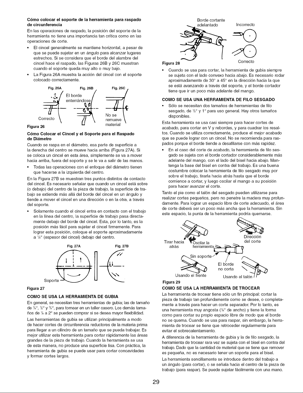
C6mo colocar el soporte de la herramienta para raspado
de circunferencia
En las operaciones de raspado, la posici6n del soporte de la
herramienta no tiene una importancia tan critica como en las
operaciones de corte.
• El cincel generalmente se mantiene horizontal, a pesar de
que se puede sujetar en un _.ngulo para alcanzar lugares
estrechos. Si se considera que el borde del alambre del
cincel hace el raspado, las Figuras 26B y 26C muestran
cuando el soporte queda muy alto o muy bajo.
• La Figura 26A muestra la accidn del cincel con el soporte
colocado correctamente.
Fig. 26A Fig. 26B Fig. 26C ,
, '_o/ El borde /
_ enterr_..
C No se \
orrecto \ J \ remueve \
Figura 26 material
C6mo Colocar el Cincel y el Soporte para el Raspado
de Di_metro
Cuando se raspa en el di_.metro, esa parte de superficie a
la derecha del centro se mueve hacia arriba (Figura 27A). Si
se coloca un cincel en esta Area, simplemente se va a mover
hacia arriba, fuera del soporte y se le va a salir de las manos.
• Todas las operaciones con el enfoque del di_.metro tienen
que hacerse a la izquierda del centro.
En la Figura 27B se muestran tres puntos distintos de contacto
del cincel. Es necesario se_alar que cuando un cincel est,. sobre
(o debajo) del centro de la pieza de trabajo, la superficie de tra-
bajo se extiende m_.s all_. del borde del cincel en un _.ngulo y
tiende a mover el cincel en una direccidn o en la otra, a trav6s
del soporte.
• Solamente cuando el cincel entra en contacto con el trabajo
en la linea del centro, la superficie de trabajo pasa directa-
mente debajo del borde del cincel. Esta, por Io tanto, es la
posicidn m_.s f_.cil para sujetar el cincel firmemente. Para
Iograr esta posicidn, coloque el soporte aproximadamente
a 1/?, (espesor del cincel) debajo del centro.
Fig. 27A
Soport_
Figura 27
Fig. 27B
COMO SE USA LA HERRAMIENTA DE GUBIA
En general, se necesitan tres herramientas de gubia; las de tama_o
de 1/4",1/2"y 3/4", para tornear en un taller casero. Los dem_.s tama-
_os de 1/8a 2" se pueden comprar si se desea mayor flexibilidad.
Las herramientas de gubia se utilizan principalmente a modo
de hacer cortes de circunferencia reductores de la materia prima
para Ilegar a un cilindro de un tama_o que se pueda trabajar. Es
mejor utilizar esta herramienta para cortar r_.pidamente las Areas
grandes de la pieza de trabajo. Cuando la herramienta se usa
de esta manera, no produce una superficie lisa. Con pr_.ctica, la
herramienta de gubia se puede usar para cortar concavidades
y formar cortes largos.
Figura 28
Borde cortante
adelantado
Incorrecto
Correcto
Cuando se usa para cortar, la herramienta de gubia siempre
se sujeta con el lado convexo hacia abajo. Es necesario rodar
aproximadamente de 30 ° a 45 ° en la direcci6n hacia la que
se est,. avanzando a trav6s del soporte, y el borde cortador
tiene que ir un poco m_.s adelante del mango.
COMO SE USA UNA HERRAMIENTA DE FILO SESGADO
• S61o se necesitan dos tama_os de herramientas de filo
sesgado, de W' y 1" para uso general. Hay otros tama_os
disponibles.
Esta herramienta se usa casi siempre para hacer cortes de
acabado, para cortar en V y rebordes, y para cuadrar los resal-
tos. Cuando se utiliza correctamente, produce el mejor acabado
que se puede Iograr con un cincel. No se recomienda para ras-
pados porque el borde tiende a desafilarse con m_.s rapidez.
• En el caso del corte de acabado, la herramienta de filo ses-
gado se sujeta con el borde cortador considerablemente m_.s
adelante del mango, con el lado del bisel hacia abajo. Man-
tenga la base del bisel en contra del trabajo. Es una buena
costumbre colocar la herramienta de filo sesgado muy por
sobre el trabajo, tirarla hacia atr_.s hasta que el borde
comience a cortar, y luego oscilar el mango a su posicidn
para hacer avanzar el corte.
Tanto el pie como el taldn del sesgado pueden utilizarse para
realizar cortes peque_os, pero no penetre la madera muy profun-
damente. Para Iograr un espacio libre de corte adecuado, el Area
de corte deber_, ser un poco m_.s ancha que la herramienta. Sin
este espacio, la punta de la herramienta podria quemarse.
Direcci6n
Tirar hacia la del corte
atrfis herramienta_
_soporte"" /
El borde
;_"--,._ _,,,_ no corta
Usando el frente Usando el
Figura 29
COMO SE USA LA HERRAMIENTA DE TROCEAR
La herramienta de trocear tiene s61o un fin principal: cortar la
pieza de trabajo tan profundamente como se desee, o completa-
mente a trav6s para hacer un corte separador. Por Io tanto, es
una herramienta muy angosta (1/?, de ancho) y tiene la forma
como para cortar su propio espacio libre de modo que el borde
no se quema. Cuando se usa para raspar, sin embargo, la herra-
mienta de trocear se tiene que retroceder regularmente para
evitar el sobrecalentamiento.
A diferencia de la herramienta de gubia y la de filo sesgado, la
herramienta de trocear rara vez se sujeta con el bisel en contra del
trabajo. Dado que la cantidad de material que se tiene que remover
es peque_a, no es necesario tener un soporte para el bisel.
La herramienta sencillamente se introduce dentro del trabajo a
un _.ngulo (para cortar), o se se_ala hacia el centro de la pieza de
trabajo (para raspar). Se puede sujetar f_.cilmente con una mano.
29
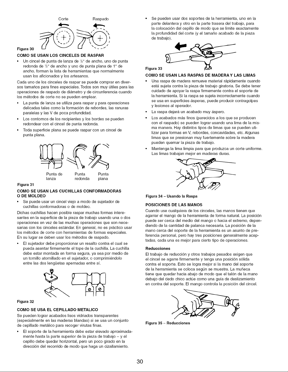
Corte Raspado
Figura 30
COMO SE USAN LOS CINCELES DE RASPAR
• Un cincel de punta de lanza de 1/2"de ancho, uno de punta
redonda de 1/2"de ancho y uno de punta plana de 1" de
ancho, forman la lista de herramientas que normalmente
usan los aficionados y los artesanos.
Cada uno de los cinceles de raspar se puede comprar en diver-
sos tamafios para fines especiales. Todos son muy Qtiles para las
operaciones de raspado de di_.metro y de circunferencia cuando
los metodos de corte no se pueden emplear.
• La punta de lanza se utiliza para raspar y para operaciones
delicadas tales como la formacidn de rebordes, las ranuras
paralelas y las V de poca profundidad.
• Los contornos de los recipientes y los bordes se pueden
redondear con el cincel de punta redonda.
• Toda superficie plana se puede raspar con un cincel de
punta plana.
Punta de Punta Punta
lanza redonda plana
Figura 31
COMO SE USAN LAS CUCHILLAS CONFORMADORAS
O DE MOLDEO
• Se puede usar un cincel viejo a modo de sujetador de
cuchillas conformadoras o de moldeo.
Dichas cuchillas hacen posible raspar muchas formas intere-
santes en la superficie de la pieza de trabajo usando una o dos
operaciones en vez de las muchas operaciones que son nece-
sarias con los cinceles est_.ndar. En general, no es pr_tctico usar
los metodos de corte con herramientas de formas especiales.
En su lugar se deben usar los metodos de raspado.
• El sujetador debe proporcionar un resalto contra el cual se
pueda asentar firmemente el tope de la cuchilla. La cuchilla
debe estar montada en forma segura, ya sea por medio de
un tornillo atornillado en el sujetador, o comprimiendolo
entre las dos lengQetas apernadas entre sL
Figura 32
COMO SE USA EL CEPILLADO METALICO
Se pueden Iograr acabados lisos vidriados transparentes
(especialmente en las maderas blandas) si se usa un conjunto
de cepillado met_.lico para recoger virutas finas.
• El soporte de la herramienta debe estar elevado aproximada-
mente hasta la parte superior de la pieza de trabajo - y el
cepillo debe quedar horizontal, pero un poco girado en la
direcci6n del recorrido de modo que haga un cizallamiento.
• Se pueden usar dos soportes de la herramienta, uno en la
parte delantera y otro en la parte trasera del trabajo, para
la colocaci6n del cepillo de modo que se limite exactamente
la profundidad del corte (y el tamafio acabado de la pieza
de trabajo).
Figura 33 _"__
COMO SE USAN LAS RASPAS DE MADERAY LAS LIMAS
• Una raspa de madera remueve material r_.pidamente cuando
est,. sujeta contra la pieza de trabajo giratoria. Se debe tener
cuidado de apoyar la raspa firmemente contra el soporte de
la herramienta. Si la raspa se sujeta incorrectamente cuando
se usa en superficies _.speras, puede producir contragolpes
y lesiones al operador.
• La raspa dejar_, un acabado muy _.spero.
• Los acabados m_.s finos (parecidos a los que se producen
con el raspado) se pueden Iograr usando una lima de la mis-
ma manera. Hay distintos tipos de limas que se pueden uti-
lizar para formas en V, rebordes, concavidades, etc. Algunas
limas que se presionan muy fuertemente sobre la madera
pueden quemar la pieza de trabajo.
• Mantenga la lima limpia para que produzca un corte uniforme.
Las limas trabajan mejor en maderas duras.
Figura 34 - Usando la Raspa
POSICIONES DE LAS MANOS
Cuando use cualquiera de los cinceles, las manos tienen que
agarrar el mango de la herramienta de forma natural. La posici6n
puede ser cerca del medio del mango o hacia el extremo, depen-
diendo de la cantidad de palanca necesaria. La posici6n de la
mano cerca del soporte de la herramienta es un asunto de pre-
ferencia personal, pero hay tres posiciones generalmente acep-
tadas, cada una es mejor para cierto tipo de operaciones.
Reducciones
El trabajo de reducci6n y otros trabajos pesados exigen que
el cincel se agarre firmemente y tenga una posici6n s61ida
contra el soporte. Esto se Iogra mejor si la mano del soporte
de la herramienta se coloca segQn se muestra. La mufieca
tiene que quedar hacia abajo de modo que el tal6n de la mano
debajo del dedo chico actQe como una guia de deslizamiento
en contra del soporte. El mango controla la posici6n del cincel.
Figura 35 - Reducciones
30
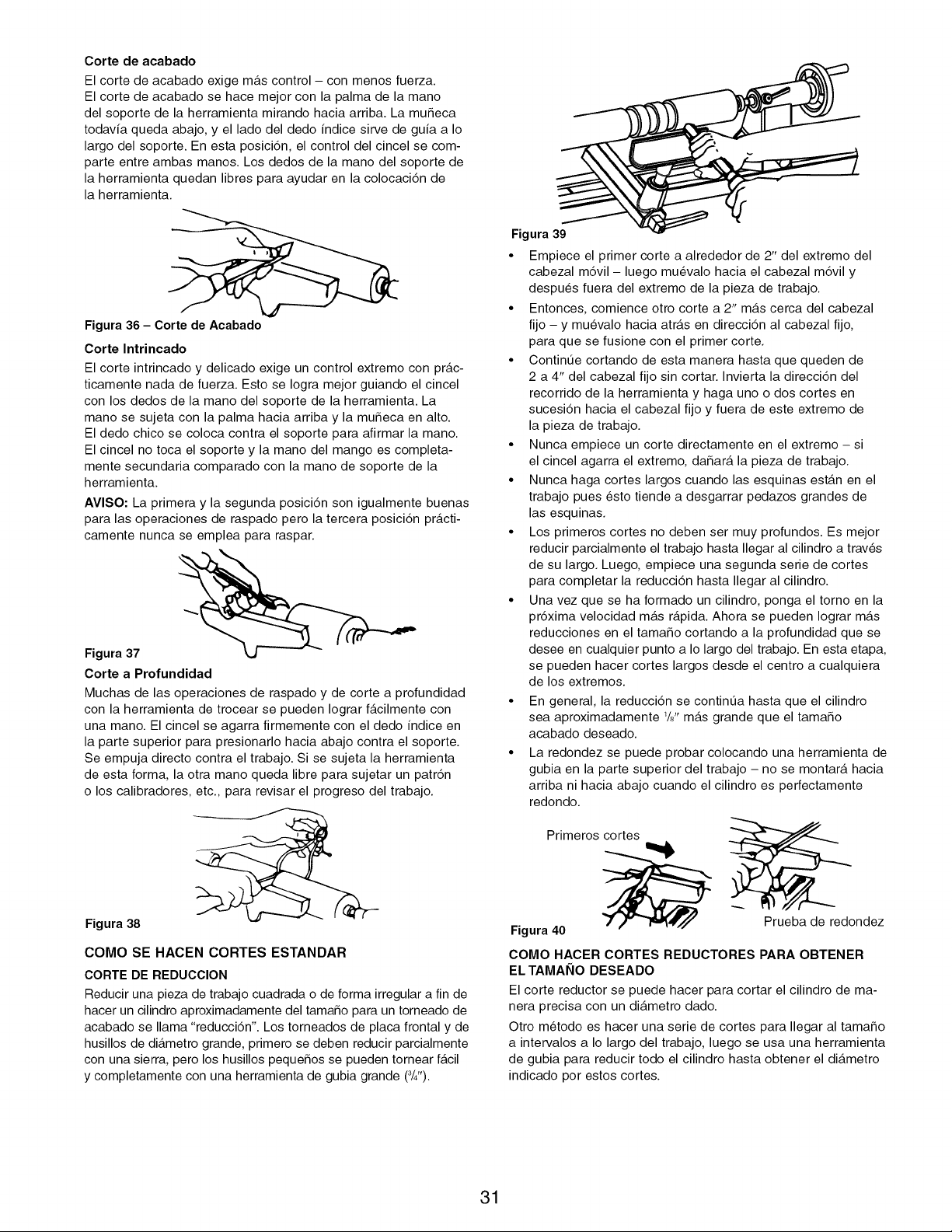
Corte de acabado
El corte de acabado exige m_.s control - con menos fuerza.
El corte de acabado se hace mejor con la palma de la mano
del soporte de la herramienta mirando hacia arriba. La muSeca
todav[a queda abajo, y el lado del dedo [ndice sirve de gu[a a Io
largo del soporte. En esta posici6n, el control del cincel se com-
parte entre ambas manos. Los dedos de la mano del soporte de
la herramienta quedan libres para ayudar en la colocaci6n de
la herramienta.
Figura 36 - Corte de Acabado
Corte Intrincado
El corte intrincado y delicado exige un control extremo con pr_.c-
ticamente nada de fuerza. Esto se Iogra mejor guiando el cincel
con los dedos de la mano del soporte de la herramienta. La
mano se sujeta con la palma hacia arriba y la muSeca en alto.
El dedo chico se coloca contra el soporte para afirmar la mano.
El cincel no toca el soporte y la mano del mango es completa-
mente secundaria comparado con la mano de soporte de la
herramienta.
AVlSO: La primera y la segunda posici6n son igualmente buenas
para las operaciones de raspado pero la tercera posici6n pr_.cti-
camente nunca se emplea para raspar.
Figura 37
Corte a Profundidad
Muchas de las operaciones de raspado y de corte a profundidad
con la herramienta de trocear se pueden Iograr f_.cilmente con
una mano. El cincel se agarra firmemente con el dedo [ndice en
la parte superior para presionarlo hacia abajo contra el soporte.
Se empuja directo contra el trabajo. Si se sujeta la herramienta
de esta forma, la otra mano queda libre para sujetar un patr6n
o los calibradores, etc., para revisar el progreso del trabajo.
Figura 38
COMO SE HACEN CORTES ESTANDAR
CORTE DE REDUCCION
Reducir una pieza de trabajo cuadrada o de forma irregular a fin de
hacer un cilindro aproximadamente del tamaSo para un torneado de
acabado se llama "reducci6n". Los torneados de placa frontal y de
husillos de di_.metro grande, primero se deben reducir parcialmente
con una sierra, pero los husillos pequeSos se pueden tornear f_.cil
y completamente con una herramienta de gubia grande (3/4").
Figura 39
• Empiece el primer corte a alrededor de 2" del extremo del
cabezal m6vil - luego muevalo hacia el cabezal m6vil y
despues fuera del extremo de la pieza de trabajo.
• Entonces, comience otro corte a 2" m_.s cerca del cabezal
fijo - y muevalo hacia atr_.s en direcci6n al cabezal fijo,
para que se fusione con el primer corte.
• Contint_e cortando de esta manera hasta que queden de
2 a 4" del cabezal fijo sin cortar. Invierta la direcci6n del
recorrido de la herramienta y haga uno o dos cortes en
sucesi6n hacia el cabezal fijo y fuera de este extremo de
la pieza de trabajo.
• Nunca empiece un corte directamente en el extremo - si
el cincel agarra el extremo, daSar_, la pieza de trabajo.
• Nunca haga cortes largos cuando las esquinas est_.n en el
trabajo pues esto tiende a desgarrar pedazos grandes de
las esquinas.
• Los primeros cortes no deben ser muy profundos. Es mejor
reducir parcialmente el trabajo hasta Ilegar al cilindro a trav6s
de su largo. Luego, empiece una segunda serie de cortes
para completar la reducci6n hasta Ilegar al cilindro.
• Una vez que se ha formado un cilindro, ponga el torno en la
pr6xima velocidad mAs rApida. Ahora se pueden Iograr mAs
reducciones en el tamaSo cortando a la profundidad que se
desee en cualquier punto a Io largo del trabajo. En esta etapa,
se pueden hacer cortes largos desde el centro a cualquiera
de los extremos.
• En general, la reducci6n se contint_a hasta que el cilindro
sea aproximadamente 1/8"m_.s grande que el tamaSo
acabado deseado.
• La redondez se puede probar colocando una herramienta de
gubia en la parte superior del trabajo - no se montar_t hacia
arriba ni hacia abajo cuando el cilindro es perfectamente
redondo.
Primeros cortes
Figura 40 _ Prueba de redondez
COMO HACER CORTES REDUCTORES PARA OBTENER
EL TAMAI_IO DESEADO
El corte reductor se puede hacer para cortar el cilindro de ma-
nera precisa con un di_.metro dado.
Otro metodo es hacer una serie de cortes para Ilegar al tamaSo
a intervalos a Io largo del trabajo, luego se usa una herramienta
de gubia para reducir todo el cilindro hasta obtener el di_.metro
indicado por estos cortes.
31
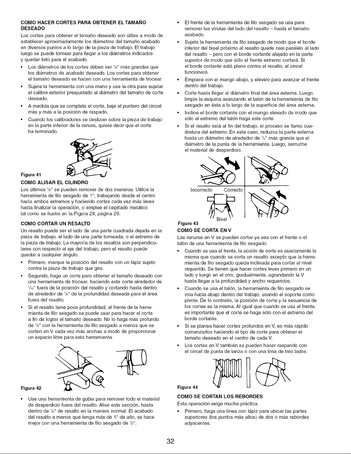
COMO HACER CORTES PARA OBTENER ELTAMAI_IO
DESEADO
Los cortes para obtener el tama_o deseado son _tiles a modo de
establecer aproximadamente los di_.metros del tamaSo acabado
en diversos puntos a Io largo de la pieza de trabajo. El trabajo
luego se puede tornear para Ilegar a los di_.metros indicados
y quedar listo para el acabado.
• Los di_.metros de los cortes deben ser 1/8'1m_.s grandes que
los di_tmetros de acabado deseado. Los cortes para obtener
el tamaSo deseado se hacen con una herramienta de trocear.
• Sujete la herramienta con una mano y use la otra para sujetar
el calibre exterior preajustado al di_.metro del tamaSo de corte
deseado.
• A medida que se completa el corte, baje el puntero del cincel
m_ts y m_.s a la posici6n de raspado.
• Cuando los calibradores se deslizan sobre la pieza de trabajo
en la parte inferior de la ranura, quiere decir que el corte
ha terminado.
Figura 41
COMO ALISAR EL CILINDRO
Los Qltimos 1/?,se pueden remover de dos maneras. Utilice la
herramienta de filo sesgado de 1% trabajando desde el centro
hacia ambos extremos y haciendo cortes cada vez m_.s leves
hasta finalizar la operaci6n, o emplee el cepillado met_.lico
tal como se ilustra en la Figura 29, p_.gina 29.
COMO CORTAR UN RESALTO
Un resalto puede ser el lado de una parte cuadrada dejada en la
pieza de trabajo, el lado de una parte torneada, o el extremo de
la pieza de trabajo. La mayoria de los resaltos son perpendicu-
lares con respecto al eje del trabajo, pero el resalto puede
quedar a cualquier _.ngulo.
• Primero, marque la posici6n del resalto con un I_.piz sujeto
contra la pieza de trabajo que gira.
• Segundo, haga un corte para obtener el tamaSo deseado con
una herramienta de trocear, haciendo este corte alrededor de
1/17'fuera de la posici6n del resalto y cortando hasta dentro
de alrededor de 1/?,de la profundidad deseada para el Area
fuera del resalto.
• Si el resalto tiene poca profundidad, el frente de la herra-
mienta de filo sesgado se puede usar para hacer el corte
a fin de Iograr el tamaSo deseado. No Io haga m_.s profundo
de 1/8"con la herramienta de filo sesgado a menos que se
corten en V cada vez m_.s anchas a modo de proporcionar
un espacio libre para esta herramienta.
Figura 42
Use una herramienta de gubia para remover todo el material
de desperdicio fuera del resalto. Alise esta secci6n, hasta
dentro de 1/8'1de resalto en la manera normal. El acabado
del resalto a menos que tenga m_.s de 1" de alto, se hace
mejor con una herramienta de filo sesgado de 1/,Z'.
• El frente de la herramienta de filo sesgado se usa para
remover las virutas del lado del resalto - hasta el tamaSo
acabado.
• Sujete la herramienta de filo sesgado de modo que el borde
inferior del bisel pr6ximo al resalto quede casi paralelo al lado
del resalto - pero con el borde cortante alejado en la parte
superior de modo que s61o el frente extremo cortar& Si
el borde cortante est,. piano contra el resalto, el cincel
funcionar&
• Empiece con el mango abajo, y elevelo para avanzar el frente
dentro del trabajo.
• Corte hasta Ilegar al di_.metro final del Area externa. Luego,
limpie la esquina avanzando el tal6n de la herramienta de filo
sesgado en esta a Io largo de la superficie del Area externa.
• Incline el borde cortante con el mango elevado de modo que
s61o el extremo del tal6n haga este corte.
• Si el resalto ester al fin del trabajo, el proceso se llama cua-
dratura del extremo. En este caso, reduzca la parte externa
hasta un di_.metro de alrededor de 1/4"m_.s grande que el
di_.metro de la punta de la herramienta. Luego, serruche
el material de desperdicio.
Incorrecto Correcto
Figura 43
COMO SE CORTA EN V
Las ranuras en V se pueden cortar ya sea con el frente o el
tal6n de una herramienta de filo sesgado.
• Cuando se usa el frente, la acci6n de corte es exactamente la
misma que cuando se corta un resalto excepto que la herra-
mienta de filo sesgado queda inclinada para cortar al nivel
requerido. Se tienen que hacer cortes leves primero en un
lado y luego en el otro, gradualmente, agrandando la V
hasta Ilegar a la profundidad y ancho requeridos.
• Cuando se usa el tal6n, la herramienta de filo sesgado se
rota hacia abajo dentro del trabajo, usando el soporte como
pivote. De Io contrario, la posici6n de corte y la secuencia de
los cortes es la misma. AI igual que cuando se usa el frente,
es importante que el corte se haga s61o con el extremo del
borde cortante.
• Si se planea hacer cortes profundos en V, es m_.s r_.pido
comenzarlos haciendo el tipo de corte para obtener el
tamaSo deseado en el centro de cada V.
• Los cortes en V tambien se pueden hacer raspando con
el cincel de punta de lanza o con una lima de tres lados.
Figura 44
COMO SE CORTAN LOS REBORDES
Esta operaci6n exige mucha pr_.ctica.
• Primero, haga una linea con I_.piz para ubicar las partes
superiores (los puntos m_.s altos) de dos o m_.s rebordes
adyacentes.
32
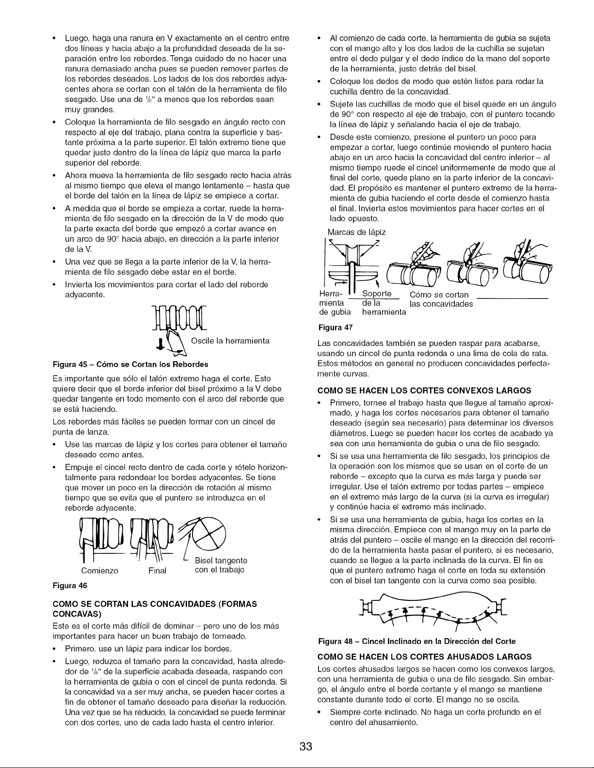
• Luego, haga una ranura en V exactamente en el centro entre
dos lineas y hacia abajo a la profundidad deseada de la se-
paraci6n entre los rebordes. Tenga cuidado de no hacer una
ranura demasiado ancha pues se pueden remover partes de
los rebordes deseados. Los lados de los dos rebordes adya-
centes ahora se cortan con el tal6n de la herramienta de filo
sesgado. Use una de 1/2"a menos que los rebordes sean
muy grandes.
• Coloque la herramienta de filo sesgado en _.ngulo recto con
respecto al eje del trabajo, plana contra la superficie y bas-
tante pr6xima a la parte superior. El tal6n extremo tiene que
quedar justo dentro de la linea de I_.piz que marca la parte
superior del reborde.
• Ahora mueva la herramienta de filo sesgado recto hacia atr_.s
al mismo tiempo que eleva el mango lentamente - hasta que
el borde del tal6n en la linea de I_.piz se empiece a cortar.
• A medida que el borde se empieza a cortar, ruede la herra-
mienta de filo sesgado en la direcci6n de la V de modo que
la parte exacta del borde que empez6 a cortar avance en
un arco de 90 ° hacia abajo, en direcci6n a la parte inferior
de la V.
• Una vez que se Ilega a la parte inferior de la V, la herra-
mienta de filo sesgado debe estar en el borde.
• Invierta los movimientos para cortar el lado del reborde
adyacente.
_Osc le la herramienta
Figura 45 - Cbmo se Cortan los Rebordes
Es importante que s61o el tal6n extremo haga el corte. Esto
quiere decir que el borde inferior del bisel pr6ximo a la V debe
quedar tangente en todo momento con el arco del reborde que
se est,. haciendo.
Los rebordes m_.s f_.ciles se pueden formar con un cincel de
punta de lanza.
• Use las marcas de I_.piz y los cortes para obtener el tamaSo
deseado como antes.
• Empuje el cincel recto dentro de cada corte y r6telo horizon-
talmente para redondear los bordes adyacentes. Se tiene
que mover un poco en la direcci6n de rotaci6n al mismo
tiempo que se evita que el puntero se introduzca en el
reborde adyacente.
Comienzo
Figura 46
Final
_gente
con eltrabajo
COMO SE CORTAN LAS CONCAVIDADES (FORMAS
CONCAVAS)
Este es el corte m_.s dificil de dominar- pero uno de los m_.s
importantes para hacer un buen trabajo de torneado.
• Primero, use un I_.piz para indicar los bordes.
• Luego, reduzca el tamaSo para la concavidad, hasta alrede-
dor de 1/8"de la superficie acabada deseada, raspando con
la herramienta de gubia 0 con el cincel de punta redonda. Si
la concavidad va a ser muy ancha, se pueden hacer cortes a
fin de obtener el tamaSo deseado para diseSar la reducci6n.
Una vez que se ha reducido, la concavidad se puede terminar
con dos cortes, uno de cada lado hasta el centro inferior.
• AI comienzo de cada corte, la herramienta de gubia se sujeta
con el mango alto y los dos lados de la cuchilla se sujetan
entre el dedo pulgar y el dedo indice de la mano del soporte
de la herramienta, justo detr_.s del bisel.
• Coloque los dedos de modo que est6n listos para rodar la
cuchilla dentro de la concavidad.
• Sujete las cuchillas de modo que el bisel quede en un _.ngulo
de 90 ° con respecto al eje de trabajo, con el puntero tocando
la linea de I_.piz y seSalando hacia el eje de trabajo.
• Desde este comienzo, presione el puntero un poco para
empezar a cortar, luego continQe moviendo el puntero hacia
abajo en un arco hacia la concavidad del centro inferior - al
mismo tiempo ruede el cincel uniformemente de modo que al
final del corte, quede piano en la parte inferior de la concavi-
dad. El prop6sito es mantener el puntero extremo de la herra-
mienta de gubia haciendo el corte desde el comienzo hasta
el final. Invierta estos movimientos para hacer cortes en el
lado opuesto.
Marcas de I_tpiz
Herra- i, Soporte C6mo se cortan
mienta de la las concavidades
de gubia herramienta
Figura 47
Las concavidades tambien se pueden raspar para acabarse,
usando un cincel de punta redonda o una lima de cola de rata.
Estos metodos en general no producen concavidades perfecta-
mente curvas.
COMO SE HACEN LOS CORTES CONVEXOS LARGOS
• Primero, tornee el trabajo hasta que Ilegue al tamaSo aproxi-
mado, y haga los cortes necesarios para obtener el tamaSo
deseado (segQn sea necesario) para determinar los diversos
di_tmetros. Luego se pueden hacer los cortes de acabado ya
sea con una herramienta de gubia o una de filo sesgado.
• Si se usa una herramienta de filo sesgado, los principios de
la operaci6n son los mismos que se usan en el corte de un
reborde - excepto que la curva es m_.s larga y puede ser
irregular. Use el tal6n extremo por todas partes - empiece
en el extremo m_.s largo de la curva (si la curva es irregular)
y continQe hacia el extremo m_.s inclinado.
• Si se usa una herramienta de gubia, haga los cortes en la
misma direcci6n. Empiece con el mango muy en la parte de
atr_.s del puntero - oscile el mango en la direcci6n del recorri-
do de la herramienta hasta pasar el puntero, si es necesario,
cuando se Ilegue a la parte inclinada de la curva. El fin es
que el puntero extremo haga el corte en toda su extensi6n
con el bisel tan tangente con la curva como sea posible.
Figura 48 - Cincel Inclinado en la Direccibn del Corte
COMO SE HACEN LOS CORTES AHUSADOS LARGOS
Los cortes ahusados largos se hacen como los convexos largos,
con una herramienta de gubia o una de filo sesgado. Sin embar-
go, el _tngulo entre el borde cortante y el mango se mantiene
constante durante todo el corte. El mango no se oscila.
• Siempre corte inclinado. No haga un corte profundo en el
centro del ahusamiento.
33
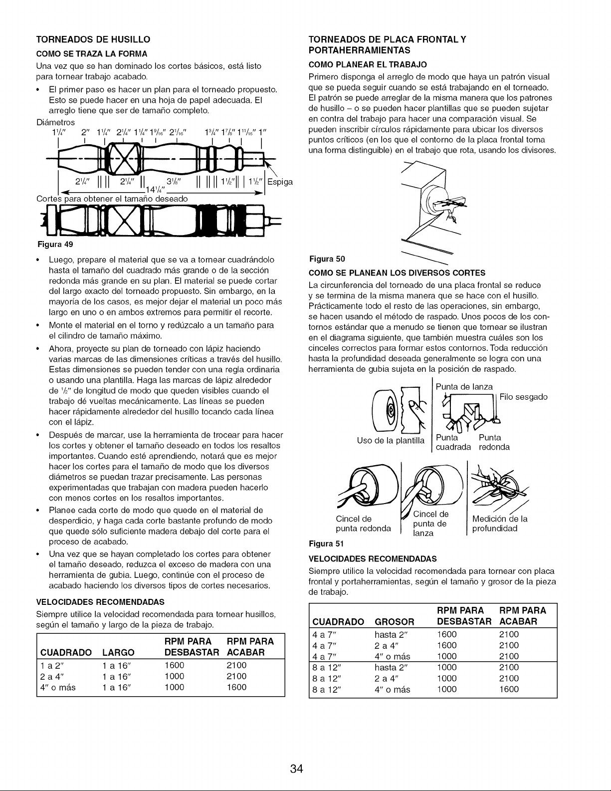
TORNEADOS DE HUSILLO
COMO SE TRAZA LA FORMA
Una vez que se han dominado los cortes b_.sicos, est,. listo
para tornear trabajo acabado.
• El primer paso es hacer un plan para el torneado propuesto.
Esto se puede hacer en una hoja de papel adecuada. El
arreglo tiene que ser de tamaSo completo.
Di_.metros
11/4" 2" 1W' 2W' 1W'19M ' 21/16" ldJ' 17/8"I"M' 1"
ql[ 21/41tIII 11141/4,,31/J' IIIIII11/2'11111/9"Espiga
Cortes para obtener el tamaSo deseado
Figura 49
• Luego, prepare el material que se va a tornear cuadr_.ndolo
hasta el tamaSo del cuadrado m_.s grande o de la secci6n
redonda m_.s grande en su plan. El material se puede cortar
del largo exacto del torneado propuesto. Sin embargo, en la
mayoria de los casos, es mejor dejar el material un poco m_.s
largo en uno o en ambos extremos para permitir el recorte.
• Monte el material en el torno y redQzcalo a un tamaSo para
el cilindro de tamaSo m_.ximo.
• Ahora, proyecte su plan de torneado con I_.piz haciendo
varias marcas de las dimensiones criticas a trav6s del husillo.
Estas dimensiones se pueden tender con una regla ordinaria
o usando una plantilla. Haga las marcas de I_.piz alrededor
de 1/9"de Iongitud de modo que queden visibles cuando el
trabajo de vueltas mec_.nicamente. Las lineas se pueden
hacer r_.pidamente alrededor del husillo tocando cada linea
con el I_.piz.
• Despues de marcar, use la herramienta de trocear para hacer
los cortes y obtener el tamaSo deseado en todos los resaltos
importantes. Cuando est6 aprendiendo, notarY, que es mejor
hacer los cortes para el tamaSo de modo que los diversos
di_.metros se puedan trazar precisamente. Las personas
experimentadas que trabajan con madera pueden hacerlo
con menos cortes en los resaltos importantes.
• Planee cada corte de modo que quede en el material de
desperdicio, y haga cada corte bastante profundo de modo
que quede s61o suficiente madera debajo del corte para el
proceso de acabado.
• Una vez que se hayan completado los cortes para obtener
el tamaSo deseado, reduzca el exceso de madera con una
herramienta de gubia. Luego, continQe con el proceso de
acabado haciendo los diversos tipos de cortes necesarios.
VELOClDADES RECOMENDADAS
Siempre utilice la velocidad recomendada para tornear husillos,
segL_n el tamaSo y largo de la pieza de trabajo.
RPM PARA RPM PARA
CUADRADO LARGO DESBASTAR ACABAR
1 a2" 1 a16" 1600 2100
2 a 4" 1 a 16" 1000 2100
4" o m_.s 1 a 16" 1000 1600
TORNEADOS DE PLACA FRONTAL Y
PORTAHERRAMIENTAS
COMO PLANEAR EL TRABAJO
Primero disponga el arreglo de modo que haya un patr6n visual
que se pueda seguir cuando se est,. trabajando en el torneado.
El patr6n se puede arreglar de la misma manera que los patrones
de husillo - o se pueden hacer plantillas que se pueden sujetar
en contra del trabajo para hacer una comparaci6n visual. Se
pueden inscribir cffculos r_.pidamente para ubicar los diversos
puntos criticos (en los que el contorno de la placa frontal toma
una forma distinguible) en el trabajo que rot& usando los divisores.
Figura 50
COMO SE PLANEAN LOS DIVERSOS CORTES
La circunferencia del torneado de una placa frontal se reduce
y se termina de la misma manera que se hace con el husillo.
Pr_.cticamente todo el resto de las operaciones, sin embargo,
se hacen usando el metodo de raspado. Unos pocos de los con-
tornos est_.ndar que a menudo se tienen que tornear se ilustran
en el diagrama siguiente, que tambien muestra cu_.les son los
cinceles correctos para formar estos contornos. Toda reducci6n
hasta la profundidad deseada generalmente se Iogra con una
herramienta de gubia sujeta en la posici6n de raspado.
Uso de la plantilla
Punta de lanza
Filo sesgado
Punta Punta
cuadrada redonda
Cincel de
punta redonda
Figura 51
Cincel de
punta de
lanza
VELOCIDADES RECOMENDADAS
Medici6n de la
profundidad
Siempre utilice la velocidad recomendada para tornear con placa
frontal y portaherramientas, segQn el tamaSo y grosor de la pieza
de trabajo.
RPM PARA RPM PARA
CUADRADO GROSOR DESBASTAR ACABAR
4 a 7" hasta 2" 1600 2100
4 a 7" 2 a 4" 1600 2100
4 a 7" 4" o mas 1000 2100
8 a 12" hasta 2" 1000 21 O0
8 a 12" 2 a 4" 1000 2100
8 a 12" 4" o mas 1000 1600
34
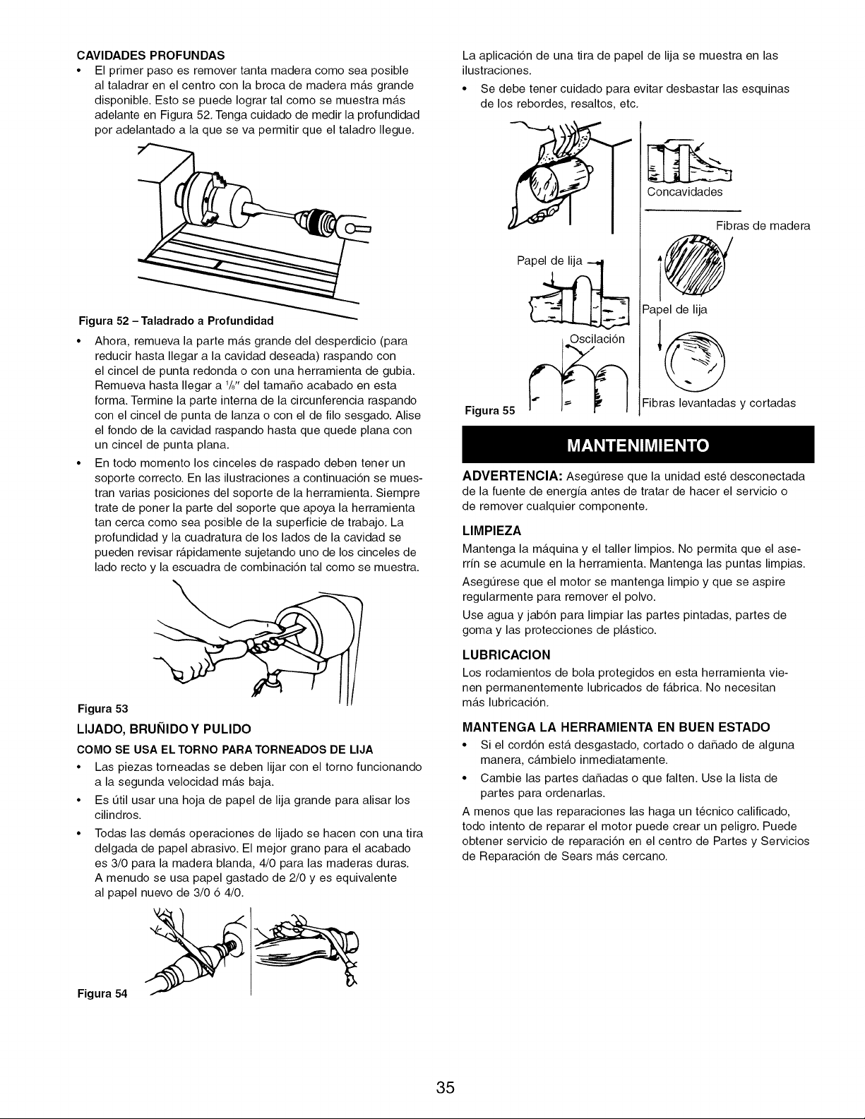
CAVlDADES PROFUNDAS
• El primer paso es remover tanta madera como sea posible
al taladrar en el centro con la broca de madera m_.s grande
disponible. Esto se puede Iograr tal como se muestra m_.s
adelante en Figura 52. Tenga cuidado de medir la profundidad
por adelantado a la que se va permitir que el taladro Ilegue.
O::=
Figura 54
Figura 52 -Taladrado a Profundidad
• Ahora, remueva la parte m_.s grande del desperdicio (para
reducir hasta Ilegar a la cavidad deseada) raspando con
el cincel de punta redonda o con una herramienta de gubia.
Remueva hasta Ilegar a 1/8" del tamaSo acabado en esta
form& Termine la parte interna de la circunferencia raspando
con el cincel de punta de lanza o con el de filo sesgado. Alise
el rondo de la cavidad raspando hasta que quede plana con
un cincel de punta plan&
• En todo momento los cinceles de raspado deben tener un
soporte correcto. En las ilustraciones a continuaci6n se mues-
tran varias posiciones del soporte de la herramienta. Siempre
trate de poner la parte del soporte que apoya la herramienta
tan cerca como sea posible de la superficie de trabajo. La
profundidad y la cuadratura de los lados de la cavidad se
pueden revisar r_.pidamente sujetando uno de los cinceles de
lado recto y la escuadra de combinaci6n tal como se muestra.
Figura 53
LIJADO, BRUNIDOY PULIDO
COMO SE USA EL TORNO PARA TORNEADOS DE LIJA
• Las piezas torneadas se deben lijar con el torno funcionando
a la segunda velocidad m_.s baja.
• Es L_til usar una hoja de papel de lija grande para alisar los
cilindros.
• Todas las demas operaciones de lijado se hacen con una tira
delgada de papel abrasivo. El mejor grano para el acabado
es 3/0 para la madera blanda, 4/0 para las maderas duras.
A menudo se usa papel gastado de 2/0 yes equivalente
al papel nuevo de 3/0 6 4/0.
La aplicaci6n de una tira de papel de lija se muestra en las
ilustraciones.
• Se debe tener cuidado para evitar desbastar las esquinas
de los rebordes, resaltos, etc.
Figura 55
Concavidades
Fibras de madera
@
Papel de lija
Fibras levantadas y cortadas
ADVERTENCIA: AsegQrese que la unidad est6 desconectada
de la fuente de energia antes de tratar de hacer el servicio o
de remover cualquier componente.
LIMPIEZA
Mantenga la m_.quina y el taller limpios. No permita que el ase-
rrin se acumule en la herramienta. Mantenga las puntas limpias.
AsegQrese que el motor se mantenga limpio y que se aspire
regularmente para remover el polvo.
Use agua y jab6n para limpiar las partes pintadas, partes de
goma y las protecciones de pl_.stico.
LUBRICAClON
Los rodamientos de bola protegidos en esta herramienta vie-
nen permanentemente lubricados de f_.brica. No necesitan
m_.s lubricaci6n.
MANTENGA LA HERRAMIENTA EN BUEN ESTADO
• Si el cord6n est,. desgastado, cortado o daSado de alguna
manera, c_.mbielo inmediatamente.
• Cambie las partes daSadas o que falten. Use la lista de
partes para ordenarlas.
A menos que las reparaciones las haga un t6cnico calificado,
todo intento de reparar el motor puede crear un peligro. Puede
obtener servicio de reparaci6n en el centro de Partes y Servicios
de Reparaci6n de Sears m_.s cercano.
35

NOTAS
36

NOTAS
37
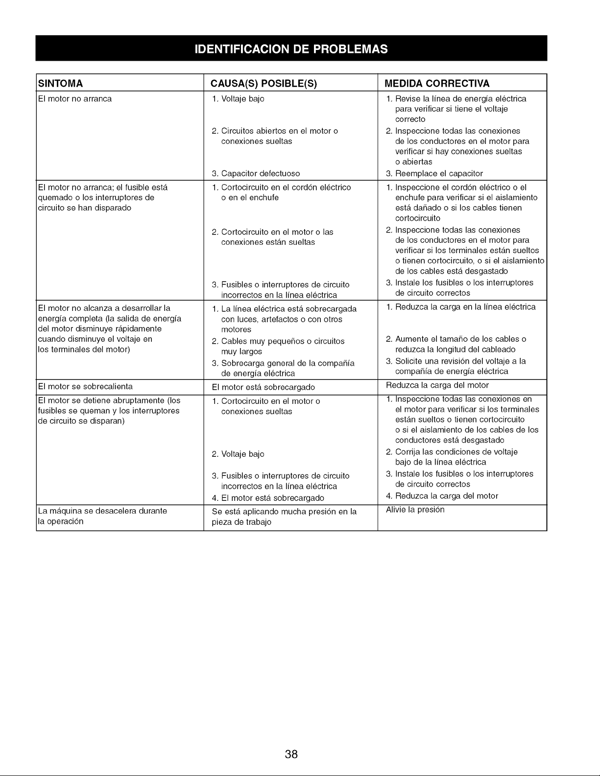
SINTOMA CAUSA(S) POSIBLE(S) MEDIDA CORRECTIVA
El motor no arranca 1. Voltaje bajo 1.
El motor no arranca; el fusible est,.
quemado o los interruptores de
circuito se han disparado
El motor no alcanza a desarrollar la
energfa completa (la salida de energfa
del motor disminuye r_.pidamente
cuando disminuye el voltaje en
los terminales del motor)
El motor se sobrecalienta
El motor se detiene abruptamente (los
fusibles se queman y los interruptores
de circuito se disparan)
La m_tquina se desacelera durante
la operaci6n
2. Circuitos abiertos en el motor o
conexiones sueltas
3. Capacitor defectuoso
1. Cortocircuito en el cord6n electrico
o en el enchufe
2. Cortocircuito en el motor o las
conexiones est_.n sueltas
3. Fusibles o interruptores de circuito
incorrectos en la Ifnea electrica
1. La Ifnea electrica est,. sobrecargada
con luces, artefactos o con otros
motores
2. Cables muy pequeSos o circuitos
muy largos
3. Sobrecarga general de la compaSfa
de energfa electrica
El motor est,. sobrecargado
1. Cortocircuito en el motor o
conexiones sueltas
2. Voltaje bajo
3. Fusibles o interruptores de circuito
incorrectos en la Ifnea electrica
4. El motor est,. sobrecargado
Se est,. aplicando mucha presi6n en la
pieza de trabajo
Revise la Ifnea de energfa electrica
para verificar si tiene el voltaje
correcto
2. Inspeccione todas las conexiones
de los conductores en el motor para
verificar si hay conexiones sueltas
o abiertas
3. Reemplace el capacitor
1. Inspeccione el cord6n electrico o el
enchufe para verificar si el aislamiento
est,. daSado o si los cables tienen
cortocircuito
2. Inspeccione todas las conexiones
de los conductores en el motor para
verificar si los terminales est_.n sueltos
o tienen cortocircuito, o si el aislamiento
de los cables est,. desgastado
3. Instale los fusibles o los interruptores
de circuito correctos
1. Reduzca la carga en la Ifnea electrica
2. Aumente el tamaSo de los cables o
reduzca la Iongitud del cableado
3. Solicite una revisi6n del voltaje a la
compaSfa de energfa electrica
Reduzca la carga del motor
1. Inspeccione todas las conexiones en
el motor para verificar si los terminales
est_.n sueltos o tienen cortocircuito
o si el aislamiento de los cables de los
conductores est,. desgastado
2. Corrija las condiciones de voltaje
bajo de la Ifnea electrica
3. Instale los fusibles o los interruptores
de circuito correctos
4. Reduzca la carga del motor
Alivie la presi6n
38
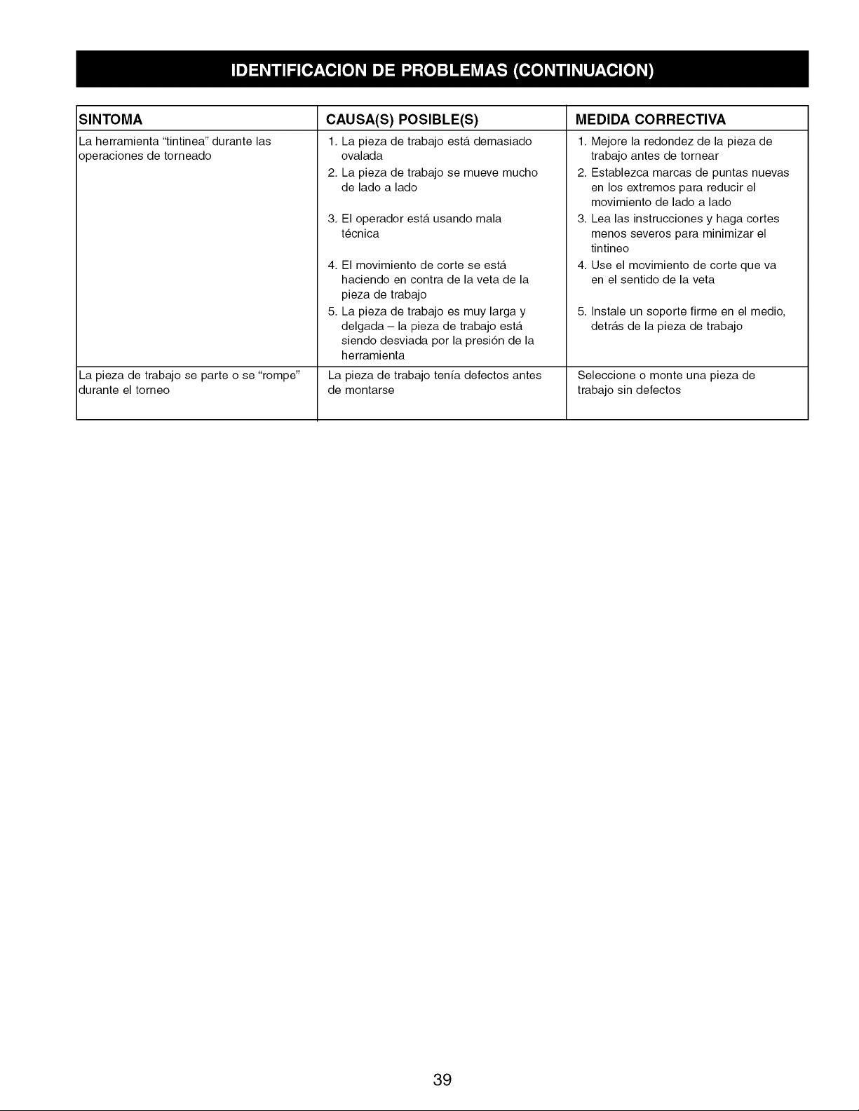
SINTOMA
La herramienta "tintinea" durante las
operaciones de torneado
La pieza de trabajo se parte o se "rompe"
durante el torneo
CAUSA(S) POSIBLE(S) MEDIDA CORRECTIVA
1.
2,
La pieza de trabajo est,. demasiado
ovalada
La pieza de trabajo se mueve mucho
de lado a lado
3. El operador est,. usando mala
t6cnica
4. El movimiento de corte se est,.
haciendo en contra de la veta de la
pieza de trabajo
5. La pieza de trabajo es muy larga y
delgada - la pieza de trabajo est,.
siendo desviada por la presi6n de la
herramienta
La pieza de trabajo tenfa defectos antes
de montarse
1. Mejore la redondez de la pieza de
trabajo antes de tornear
2. Establezca marcas de puntas nuevas
en los extremos para reducir el
movimiento de lado a lado
3. Lea las instrucciones y haga cortes
menos severos para minimizar el
tintineo
4. Use el movimiento de corte que va
en el sentido de la veta
5. Instale un soporte firme en el medio,
detr_.s de la pieza de trabajo
Seleccione o monte una pieza de
trabajo sin defectos
39

Your Home
For expert troubleshooting and home solutions advice:
www.managemyhome.com
For repair - in your home - of all major brand appliances,
lawn and garden equipment, or heating and cooling systems,
no matter who made it, no matter who sold it!
For the replacement parts, accessories and
owner's manuals that you need to do-it-yourself.
For Sears professional installation of home appliances
and items like garage door openers and water heaters.
1-800-4-MY-HOME ® (1-800-469-4663)
Call anytime, day or night (U.S.A. and Canada)
www.sears.com www.sears.ca
Our Home
For repair of carry-in items like vacuums, lawn equipment,
and electronics, call anytime for the location of your nearest
Sears Parts & Repair Service Center
1-800-488-1222 (U.S.A.) 1-800-469-4663 (Canada)
www.sears.com www.sears.ca
To purchase a protection agreement on a product serviced by Sears:
1-800-827-6655 (u.S.A.) 1-800-361-6665 (Canada)
Para pedir servicio de reparaci6n
a domicilio, y para ordenar piezas:
1-888-SU-HOGAR ®
(1-888-784-6427)
Au Canada pour service en fran(_ais:
1-800-LE-FOYER Mc
(1-800-533-6937)
www.sears.ca
® Registered Trademark / TM Trademark / SM Service Mark of Sears Brands, LLC
SM
® Marca Registrada / rM Marca de Fabrica / Marca de Servicio de Sears Brands, LLC
MCMarque de commerce / MDMarque d6posee de Sears Brands, LLC © Sears Brands, LLC