Loading ...
Loading ...
Loading ...
11
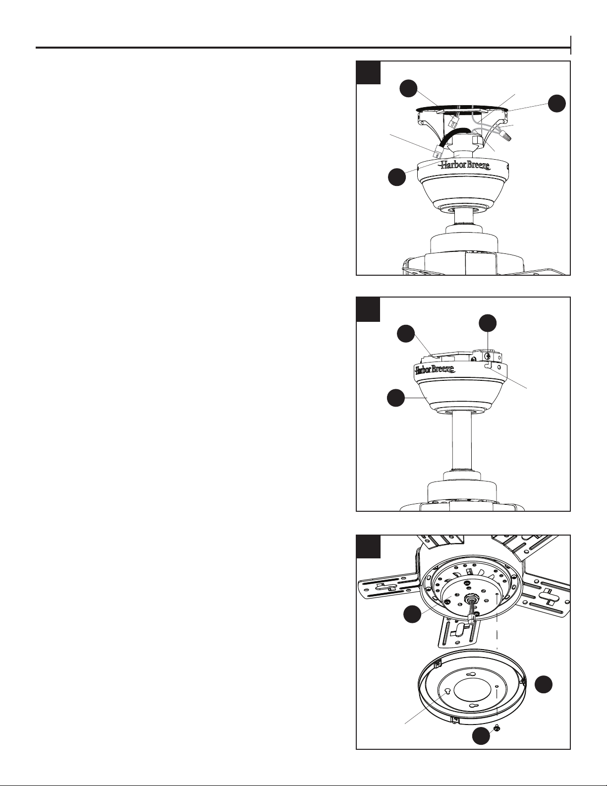
STANDARD OR ANGLE MOUNTING INSTRUCTIONS
7. Connect the 3-pin connector extending from the
downrod (A) to the 3-pin connector on lead wire (AI).
Then, connect the green/bare (ground) supply wire to
the green wires from the downrod (A) and the mounting
bracket (D).
8. Align the canopy (E) over the loose mounting bracket
screws (G) preassembled on mounting bracket
(D). Place the keyholes of the canopy (E) onto the
mounting bracket screws (G) and rotate the canopy (E)
clockwise. Secure the canopy (E) with the mounting
bracket screws (G) previously removed (Step 4, page
8). Tighten all mounting bracket screws (G) securely.
9. Remove one tter plate screws (M) from tter plate (L).
Feed the 9-pin connector through center hole in light
pan (N). Align the three key slots in the light pan (N)
with the loosened tter plate screws (M). Place the light
pan (N) over the three screws and turn the light pan (N)
clockwise. Then tighten the three tter plate screws (M).
Re-install the previously removed tter plate screw (M)
and tighten rmly.
7
9
AI
D
A
8
3-Pin
Connector
Bare/Green
(ground)
Green
Green
E
M
N
L
D
Keyhole
G
Key slot
Loading ...
Loading ...
Loading ...