Loading ...
Loading ...
Loading ...
6 7
Motor Design
In addition to the tweeter motor system being
modied to accommodate the wider duct through its
centre pole, other changes were made to provide a
more consistent drive to the voice coil.
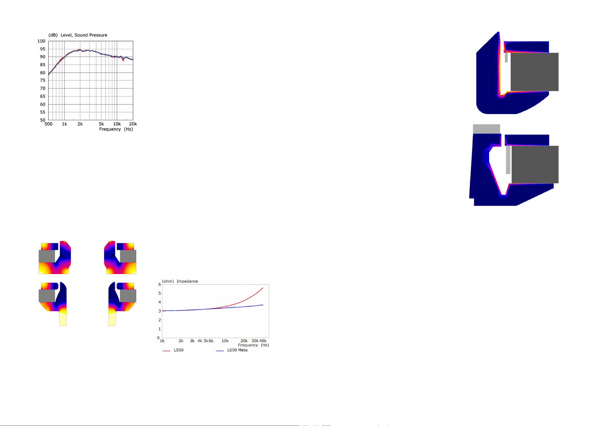
Figure 16 illustrates the difference in tweeter motor
design between the original LS50 and the LS50 Meta.
One major change is the sheer size difference of
the duct - 2.5x the surface area of that found in the
original LS50, increasing the air volume available to
the tweeter.
This ensures as much of the sound as possible from
the back of the dome is directed into the metamaterial
absorber. but also reduces non-linear distortions
caused by air pressure changes behind the tweeter.
As a tweeter moves in and out, it compresses and
decompresses the air behind it. This negatively
affects the excursion characteristics and linearity of
the tweeter The larger the air volume, the lesser the
effect.
Also notable is the increased saturation of the steel
components of the motor system. The image colour
is indicative of the magnetic strength throughout the
steel, and dark blue indicates saturation.
Normally the magnetic eld in the gap is perturbed by
the electric current in the voice coil, which changes
the force on the voice coil during every cycle of
movement. Perturbation cannot occur if the motor
system is saturated and so the force on and therefore
the motion of the voice coil more closely follows the
input signal.
Saturation did result in a drop of ux density in the gap.
This was compensated by changing the tweeter voice
coil from one to two layers, which would normally lead
to an increase in coil inductance, with a progressive
loss of sensitivity at very high frequencies. A copper
sleeve on the centre pole, which couples inductively
to the voice coil, reduces the inductance, even below
that of the LS50, as is shown by the blocked coil
measurements of gure 17.
Bass/Midrange
Motor Design
The design of the motor used in the bass/midrange
driver of the Uni-Q driver has also been modied to
reduce modulation by the movement of the voice
coil, but this time the approach is different from that
used for the tweeter, partly because the driver has an
overhung voice coil (coil longer than the magnet gap)
as opposed to the underhung coil (coil shorter than
the magnet gap) of the tweeter, which is always fully
in the steel gap.
The inductance of a voice coil presents a couple of
challenges. Higher levels of inductance create a larger
net magnetic eld as the signal passes through the
voice coil. This magnetic eld causes distortion - the
lower the inductance of the voice coil, the lower the
net magnetic eld is produced, thus lower distortion.
The inductance of the voice coil also tends to change
as the coil moves in the gap (modulation). The steel
acts as a core to increase the coil’s inductance and
the amount of steel (and therefore the inductance)
varies as the coil position changes. This variance is an
issue, as it introduces non-linear distortions into the
loudspeaker performance.
As a result, more extensive use is made of auxiliary
aluminium parts in LS50 Meta than was the case
with the original LS50. The aluminium, although non-
magnetic, is conductive and couples inductively to the
voice coil. Being a virtual short circuit, it reduces the
value of the coil’s inductance, which in turn reduces
modulation of the ux of the motor system - reducing
non-linear distortions.
The LS50 and LS50 Meta motor designs are compared
in gure 18. The aluminium parts are coloured light
grey.
Where the original LS50 features a small aluminium
ring placed between the magnet and voice coil,
LS50 Meta sports a much larger version. In addition,
another ring has been added to the top. The red
fringing in the otherwise blue steel is a measure of the
coil modulation and is seen to be much lower in the
LS50 Meta.
The LS50 Meta motor system also features an
undercut pole design to minimise the steel volume
and focus the magnetic eld more precisely on the
voice coil. Also instructive is to measure the voice
coil inductance at different frequencies and compare
different designs.
For the measurements in gure 19, the voice coil is
blocked (glued in place) at the centre (rest) position.
LS50 Meta - with the shorting rings - exhibits much
lower inductance than the other designs.
Inductance modulation was also measured at two
different frequencies (200Hz and 2kHz) against
excursion. Figure 20 clearly shows that the LS50
Meta design, with the shorting rings, exhibits the least
variation of inductance against excursion - creating
a frequency response that stays balanced, with very
little inuence from the excursion of the driver.
Figure 15
Tweeter response
With damped cavity (blue)
Without cavity (red)
Figure 16
Tweeter motor systems of LS50 (top)
and LS50 Meta (bottom).
Figure 17
Tweeter blocked impedance
Figure 18
Bass.midrange motor systems of LS50 (top)
and LS50 Meta (bottom).
Loading ...
Loading ...
Loading ...