GL400 Series
www.trimble.com
Trimble Construction Division
5475 Kellenburger Road
Dayton, Ohio 45424
USA
+1-937-245-5600 Phone
www.trimble.com
User Guide
Bedienungsanleitung
Manuel de l´utilisateur
Guida per l´uso
Gúia del usuario
Gebruikershandleiding
Operatörshandbok
Brugermanual
Guia do Usuário
Bruksanvisning
Käyttäjän opas
取扱説明書
© 2007, Trimble Navigation Limited. All rights reserved.
GL612N/GL622N
/GL622IR
GL400 Series
www.trimble.com
Trimble Construction Division
5475 Kellenburger Road
Dayton, Ohio 45424
USA
+1-937-245-5600 Phone
www.trimble.com
User Guide
Bedienungsanleitung
Manuel de l´utilisateur
Guida per l´uso
Gúia del usuario
Gebruikershandleiding
Operatörshandbok
Brugermanual
Guia do Usuário
Bruksanvisning
Käyttäjän opas
取扱説明書
© 2007, Trimble Navigation Limited. All rights reserved.
Руководство пользователя
Russ_Titel.indd 1 06.05.2008 08:38:53
© 2018, Trimble Inc., All rights reserved.
PN 111372-00 Rev. B (05/18)
Trimble - Spectra Precision Division
5475 Kellenburger Road
Dayton, Ohio 45424 U.S.A.
+1-937-245-5600 Phone
Instrukcja obsługi
GL612N/GL622N/GL622IR
111372-00 Rev. B (05/18)
d
f
h
g
i
k
i
c
e
b
a
j
l
Service and Customer Advice
North America
Trimble - Spectra Precision Division
5475 Kellenburger Road
Dayton, Ohio 45424 U.S.A.
888-527-3771 (Toll Free)
+1-937-245-5600 Phone
+1-937-482-0030 Fax
www.trimble.com
www.spectraprecision.com
www.spectralasers.com
Europe
Trimble Kaiserslautern GmbH
Am Sportplatz 5
67661 Kaiserslautern
GERMANY
+49-6301-711414 Phone
+49-6301-32213 Fax
Latin America
Trimble Navigation Limited
6505 Blue Lagoon Drive
Suite 120
Miami, FL 33126
U.S.A.
+1-305-263-9033 Phone
+1-305-263-8975 Fax
Africa & Middle East
Trimble Export Middle-East
P.O. Box 17760
Jebel Ali Free Zone, Dubai
UAE
+971-4-881-3005 Phone
+971-4-881-3007 Fax
Asia-Pacic
Trimble Navigation
Australia PTY Limited
Level 1/120 Wickham Street
Fortitude Valley, QLD 4006
AUSTRALIA
+61-7-3216-0044 Phone
+61-7-3216-0088 Fax
China
Trimble Beijing
Room 2805-07, Tengda Plaza,
No. 168 Xiwai Street
Haidian District
Beijing, China 100044
+86 10 8857 7575 Phone
+86 10 8857 7161 Fax
www.trimble.com.cn

1
TABLE OF CONTENTS
1 INTRODUCTION 3
2 FOR YOUR SAFETY 3
3 COMPONENTS 3
4 How to use the Laser System 4
4.1 Powering the Laser 4
4.1.1 Batteries 4
4.1.2 Recharging the batteries 4
4.2 RC602N Radio Remote Control 4
4.2.1 Powering the RC602N 4
4.2.2 Turning On/Off the RC602N 4
4.3 ST802/ST805 Signal Transporter 5
4.3.1 Powering the ST802/ST805 5
4.3.2 Turning On/Off the ST802/ST805 5
5 LASER SETUP 5
5.1 Turning On/Off the Laser 5
5.2 Features and functions 6
5.2.1 Standard Display 6
5.3 Standard Features 6
5.3.1 X-Y-grade entering - Digit Select mode (Default) 6
5.3.2 X-Y-grade - Step and Go mode 7
5.3.3 Rotation Mode 8
5.3.4 Manual Mode 8
6 Special MENU Features 8
6.1 Menu Navigation 8
6.2 Automatic PlaneLok Mode 9
6.3 Automatic Grade Match 10
6.4 Automatic Axis Alignment (only GL622N, GL622IR) 11
6.5 Mask Mode 11
6.6 Activating/Deactivating Standby mode 11
6.7 Start Reference Check 12
6.8 Setting Menu 12
GB

2
6.9 Info 12
6.10 Service 12
6.11 RC602N Service Menu 13
6.11.1 RF Connectivity 13
7 Special Features - Vertical Setup 13
7.1 Line Scan 13
8 Setting 13
8.1 Pairing 14
8.2 Pairing the laser with remote control 14
8.3 Pairing the laser with receiver HL760 14
8.4 Pairing the laser with the Signal Transporter (ST802/ST805) 14
8.5 Grade Entry 15
8.6 Grade Display 15
8.7 Sensitivity Selection 15
8.8 HI-alert selection 15
8.9 User Name 16
8.10 Set Password 16
8.11 Password On/Off 16
8.12 Radio (RF-Channel) 17
8.13 Select Language 17
8.14 Position Info 17
9 CALIBRATION 18
9.1 Checking Calibration of the Y- and X-Axes 18
9.2 Checking Calibration of the Z-(vertical) Axis 18
10 TROUBLESHOOTING 19
11 PROTECTING THE UNIT 20
12 CLEANING AND MAINTENANCE 20
13 PROTECTING THE ENVIRONMENT 20
14 WARRANTY 20
15 TECHNICAL DATA 21
15.1 GL612N/GL622N/GL622IR 21
15.2 RC602N 21
16 DECLARATION OF CONFORMATY 21
17 ELECTROMAGNETICAL COMPATIBILITY 22
3
1 INTRODUCTION
Thank you for choosing one of the Spectra Precision Lasers from the Trimble family of precision lasers.
The grade laser is an easy-to-use tool that offers accurate horizontal, vertical and sloped laser reference up
to 1300 ft (400 m) away using a receiver.
2 FOR YOURE SAFETY
For hazardless and safe operation, read all the user guide instructions.
• Use of this product by people other than those trained on this product may result in exposure to hazardous
laser light.
• Do not remove warning labels from the unit.
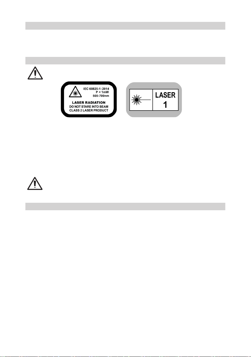
• The GL622N/GL612N is a class 2 laser (IEC 60825-1:2014).
The GL622IR is a class 1 laser (IEC 60825-1:2014).
• Never look into the laser beam or direct it to the eyes of other people.
• Always operate the unit in a way that prevents the beam from getting into people‘s eyes.
• If initial service is required, which results in the removal of the outer protective cover, removal must only be
performed by factory-trained personnel.
Caution: Use of other than the described user and calibration tools or other procedures may result
in exposure to hazardous laser light.
Caution: Using different than described at the GL612N/GL622N/GL622IR user guide, may result
in unsafe operation.
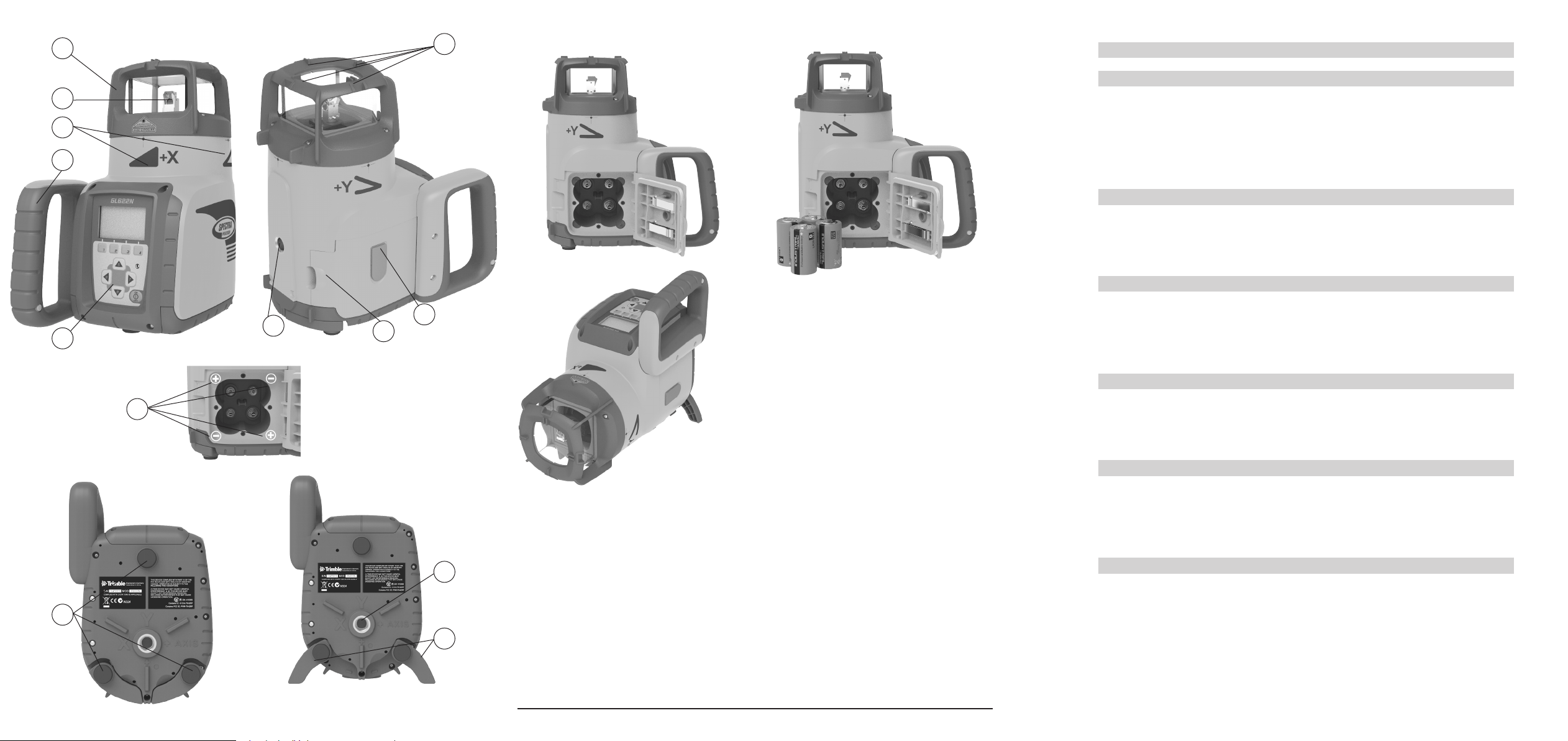
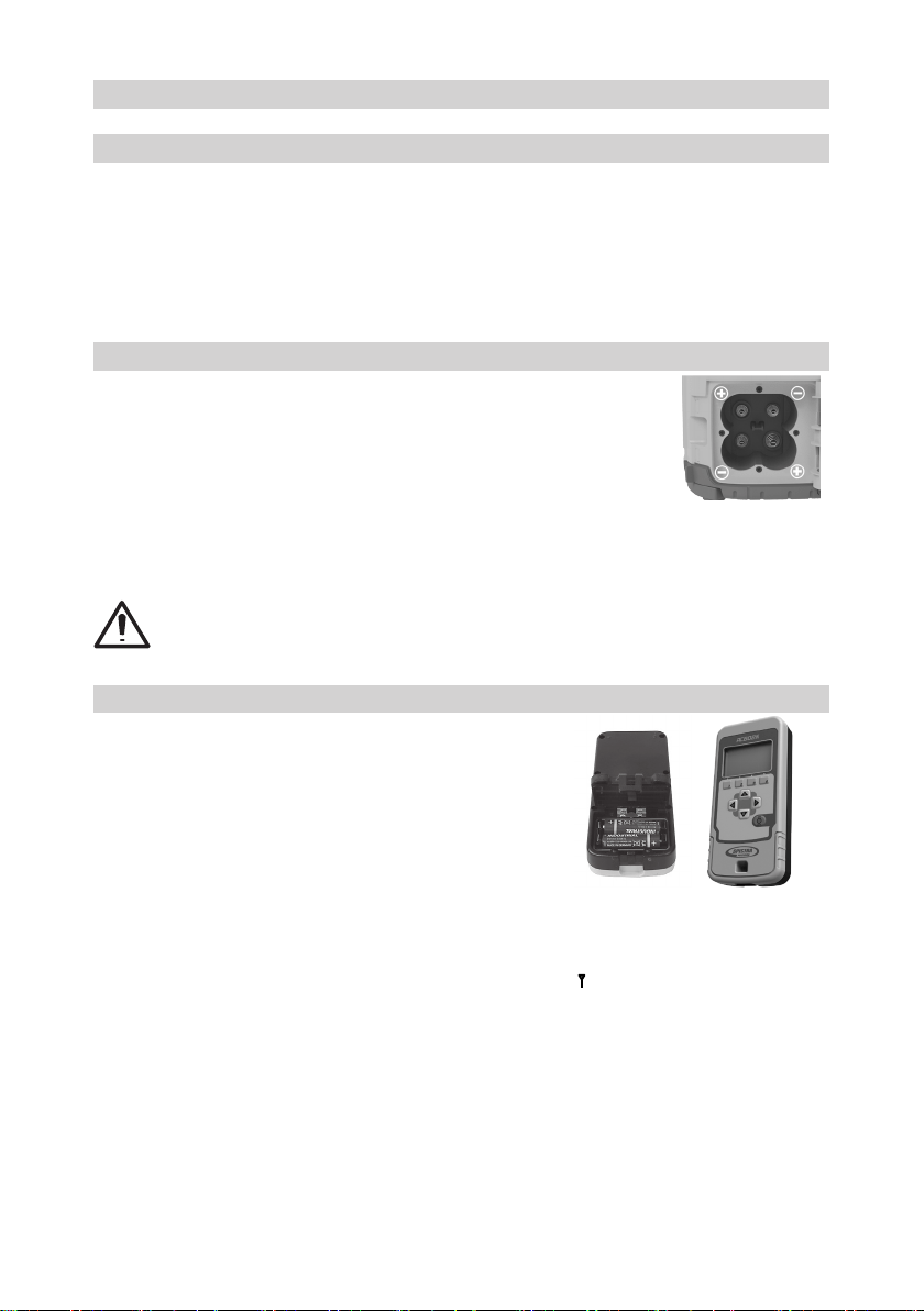
3 COMPONENTS
a Keypad/LCD-Display
b Handle
c Rotor
d Sunshade
e Axes-Alignment-Marks
f Sighting Guides/Scope Mounts
g Battery door
h Rubber Cover/Recharge Jack
i 5/8” x 11 Tripod Mounts
j Rubber Feet
k Turnable Legs
l Plus and Minus Battery Diagrams
4
4 HOW TO USE THE LASER SYSTEM
4.1 POWERING THE LASER
4.1.1 Batteries
WARNING
Ni-MH batteries may contain small amounts of harmful substances. Be sure to charge the battery
before using it for the rst time, and after not using it for an extended length of time. Charge only with
specied chargers according to device manufacturer‘s instructions. Do not open the battery, dispose
of in re or short circuit; it may ignite, explode, leak or get hot causing personal injury. Dispose in
accordance with all applicable federal, state, and local regulations. Keep the battery away from
children. If swallowed, do not induce vomiting. Seek medical attention immediately
4.1.2 Recharging the Batteries
The laser might be shipped with a rechargeable Ni-MH battery pack.
Note: The approximate charge of the batteries is shown at the left top side of the LCD.
The charger requires approx. 10 hours to charge empty rechargeable batteries.
For charging, connect the plug of the charger to the recharge jack of the battery pack.
New or long-time out-of-use rechargeable batteries reach their best performance
after being charged and recharged ve times. For Indoor applications the charger
can be used as a power supply for the laser.
Alkaline batteries can be used as a backup. Insert 4 D-cell batteries noting the plus (+) and minus (-) diagrams
inside the battery housing.
The batteries should only be charged when the laser is between 50° F and 104° F (10°C to
40°C). Charging at a higher temperature may damage the batteries. Charging at a lower
temperature may increase the charge time and decrease the charge capacity, resulting in
loss of performance and shortened life expectancy.
4.2 RC602N Radio Remote Control
4.2.1 Powering the RC602N
1. Open the battery door using a coin or similar pry device to release
the battery door tab on the RC602N. RC602N will be shipped with
alkaline batteries Rechargeable batteries can be used optional but
need to be charged externally
2. Insert two AA batteries noting the plus (+) and minus (-) diagrams
inside the battery housing.
3. Close the battery door. Push down until it “clicks” into the locked
position.
4.2.2 Turning On/Off the Radio Remote Control
The radio remote control is a hand-held device that allows you to send operational commands to the laser
from a remote location.
Press the power button to turn on the radio remote control. The symbol “ ” and additional vertical bars appear
in the right corner of the remote’s top display line indicating the radio connection status between the laser
and the remote control.
Note: When the remote control is initially turned on, the standard display (model number and software version)
appear for the rst 3 seconds, then the axes symbols and last-entered grade for each axis appear in the LCD.
With every button press, the LCD backlight is activated and turns off automatically if no button is pressed for
8 seconds.
To turn off the radio remote control, press the power button. for two secounds.
Note: 5 minutes after the last button press, the remote control turns off automatically.
5
4.3 ST802/ST805 SIGNAL TRANSPORTER
4.3.1 POWERING THE ST802/ST805
1. Open the battery door using a coin or similar pry device to release the battery door tab on the
ST802/ST805. ST802/ST805 will be shipped with alkaline batteries. Rechargeable batteries can
be used optional but need to be charged externally.
2. Insert two AA batteries noting the plus (+) and minus (-) diagrams inside the battery housing.
3. Close the battery door. Push down until it “clicks” into the locked position.
4.3.2 Turning On/Off the ST802/ST805
The signal transporter (ST) is a hand-held device that which extends the radio range of a laser which is paired
with the ST. Press the power button to power on the signal transporter. All LEDs turn on for three seconds.
Finally a ashing yellow status LED shows the signal transporter has been paired with a laser but this laser
is not available. A solid blinking yellow status LED is showing that the radio connection between the signal
transporter and the paired laser has been established.
5 LASER SETUP
Position the laser horizontally (tripod mount and rubber feet downward!) on a stable platform, wall mount or
tripod at the desired elevation.
The laser recognizes automatically whether it is used horizontally or vertically when switched on.
5.1 Turning On/Off the laser
Press the power button for one second to turn On the laser.
Press the power button for two seconds to turn Off the laser.
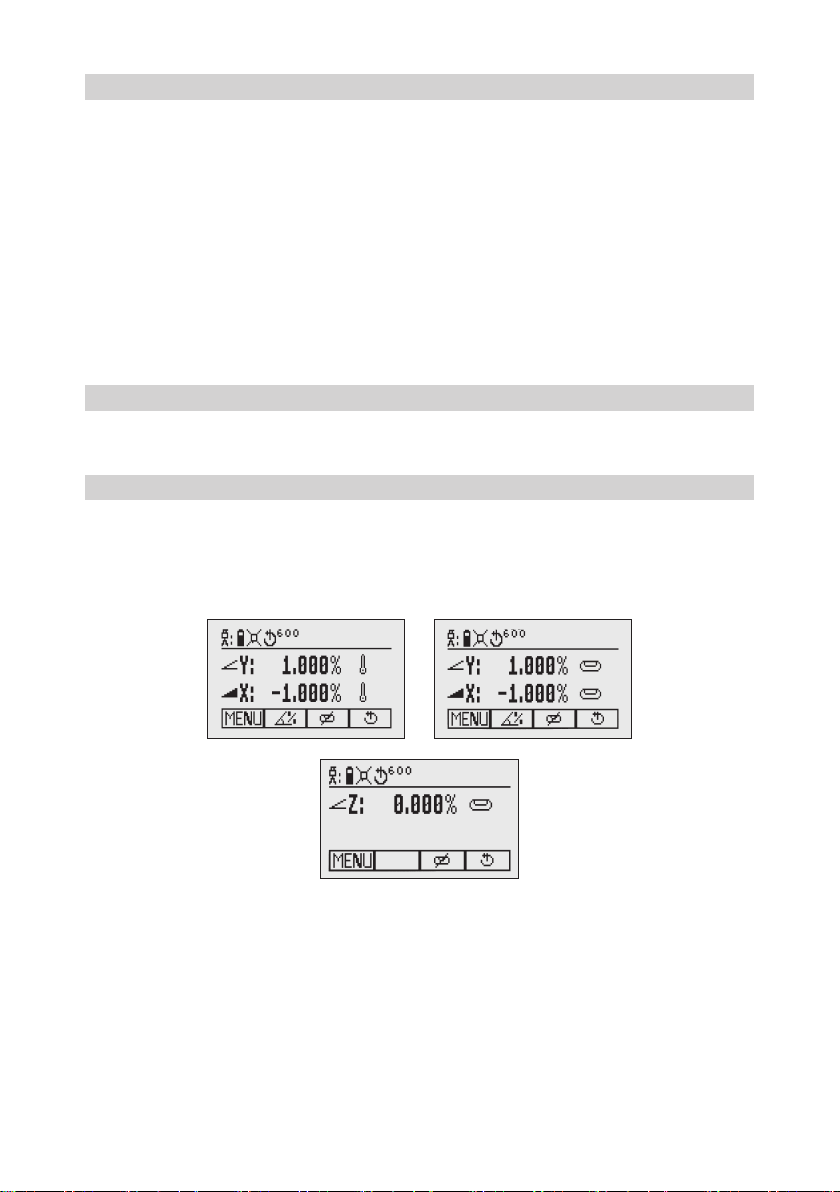
Note: When a grade value has been entered and after temperature change of more than 9°F (5°C), the unit
starts the temperature/reference check while the thermometer symbol is ashing (Pic 1).
Another temperature check takes place after 20 min. and nally every 60 min. When the temperature/reference
check has been nished, the standard display appears and the bubble symbols ash until self-leveling has
been completed (Pic 2).
If the self-leveling can’t be nished based on the selected sensitivity, an error message appears.
Pic 1 Reference check
Pic 2 Standard display horizontal
Pic 3 Standard display vertical
6
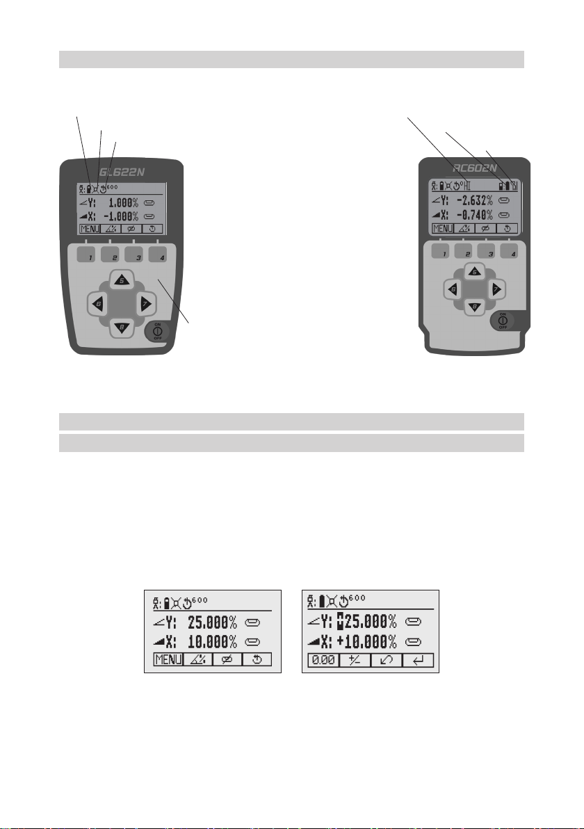
5.2 Features and Functions
5.2.1 Standard Display
The remote control mirrors the functionality of the laser keypad
Button 1: Quickly press and release starts the
MENU entry.
Button 2: Quickly press and release starts the
grade entering mode.
Button 3: Quickly press and release activates/
deactivates the manual mode.
Button 4: Quickly press and release to toggle
through the pre-selected rotation
speeds.
Button 5, 8: up/down arrow buttons.
Button 6, 7: left/right arrow buttons.
Button 9: ON/OFF button - press for 1 second to
turn on the unit; press and hold for 2
seconds to turn off the unit.
Leveling/Standby – LED (green/red)
Battery status laser HI alert function is activated
Mask selection Battery Status Remote Control
Status Radio Connectivity
Rotation speed
5.3 Standard Features
5.3.1 X-Y-grade entering – Digit Select mode (Default)
Quickly press and release button 2 (Pic 4) starts the grade entering mode.
Both grade values will be shown.
A cursor (Pic 5) blinks at the current position which can be changed.
Press/release button 1 a quick set to 0%
Press/release button 2 a change the sign in front of the grade value
Press/release button 3 a return to the standard display.
Quickly press and release button 4 to conrm the selected grade value and return to the standard display.
Press and release button 5 or 8 (down or up) to move the cursor to the X- (only GL622N/GL622IR) or Y-axis
Pressing and releasing button 6 or 7 (right or left) moves the cursor to the right/left.
Use button 1 or 2 (Plus or Minus) to set the desired digit (Pic 6).
The laser will self-level to the required grade position after conrming the grade change with button 4.
Pic 4 Standard Display
Pic 5 Grade Entry Mode
7
Note: The bubble symbols at the laser and remote control LCD will ash until the laser has been self-leveled
to the requested grade position.
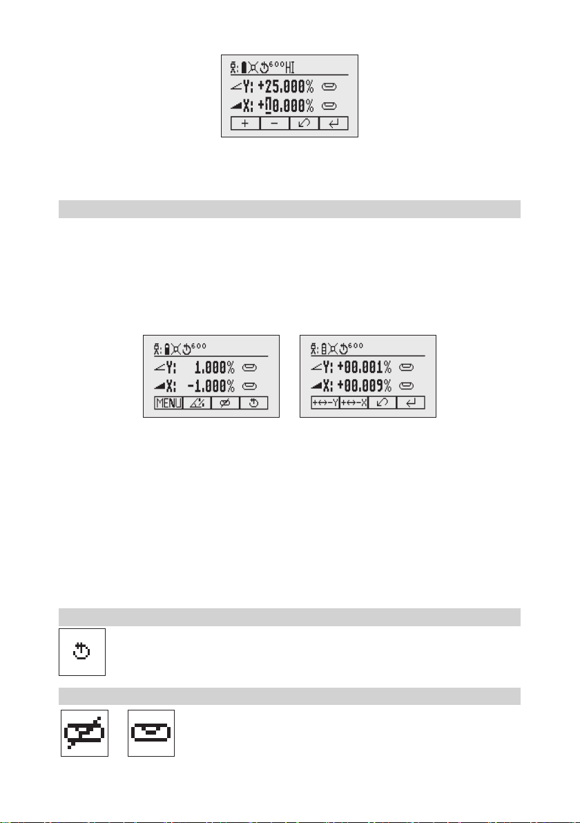
5.3.2 X-Y-grade entering – Step and Go mode
How to change to ‚Step and Go‘ mode see chapter 8.5
Quickly press and release button 2 (Pic 7) starts the grade entering mode. Both grade values will be shown.
Press/release button 1 a grade reverse Y (Pic 8)
Press/release button 2 a grade reverse X (only GL622N/GL622IR)
Press/release button 3 a return to the standard display
Quickly press and release button 4 to conrm the selected grade value and
return to the standard display
Press and hold button 6 or 7 (left/right) to change X- axis grade value (only GL622N/GL622IR) after the comma;
press and hold buttons 6 + 7 simultaneously starts X-axis quick change mode where the grade value in front
of the comma will be set to 0% and then starts changing in 1% increments.
Press and hold button 5 or 8 (up/down) for changing Y -axis grade value; press and hold buttons 5 + 8
simultaneously starts Y - axis quick change mode where the grade value in front of the comma will be set to
0% and then starts changing in 1% increments.
Note: The speed of the grade value change increases with the amount of time the button is held down.
Note: The grade value for both axes increases in 1.00% increments. When the grade value for either axis
reaches its highest amount, the grade value switches to the lowest value for that axis. For example, the value
switches from +25% to -25%.
The laser will self-level to the required grade position after conrming the grade change with button 4.
Note: The bubble symbols at the laser’s LCD will ash until the laser has been self-leveled to the requested
grade position.
5.3.3 Rotation Mode
Repeatedly pressing the button 4 toggles through 300, 600, 750 rpm regardless if the unit is in
automatic or manual mode.
5.3.4 Manual Mode
Pressing and releasing button 3 at the Standard Display activates/deactivates
the manual mode regardless if set up horizontal or vertical.
Manual mode is indicated by horizontal lines next to the axes symbols.
Pic 6 Set Digit
Pic 7 Standard Display
Pic 8 Grade Reverse
8
In Manual mode (horizontal), the Y-axis can be sloped by pressing the Up-(5) and Down-Arrow-(8) buttons on
the laser‘s keypad or the remote control. Additionally, the X-axis can be sloped by pressing the Left-(6) and
Right-(7) Arrow-buttons on the laser or remote control.
In vertical mode, the up and down arrow buttons adjust the Z-axis slope, and the left and right arrow buttons
align the laser beam to the right/left side.
To resume automatic self-leveling mode, press the manual button again.
6 Special MENU Features
6.1 Menu Navigation (Radio controlled)
Press and release button 1 at the Standard Display to enter the MENU.
The menu offers always only the features which can be selected depending on the setup (horizontal
or vertical).
The icon of the selected function will be highlighted.
A down arrow at the the right site indicates that the user can scroll down through the menu using the
button 8 (down arrow).
After going to the next menu row, an up/down arrow at the the right site indicates that the user can scroll up/
down through the menu (4 different screens) using the buttons 5/8 (up/down arrows).
Pressing and releasing button 3 changes the unit always back to the standard or previous display.
Press and release the buttons 6/7 until the desired icon at the selected menu row is highlighted.
Press and release button 4 to open the submenu OR start the selected function.
Pic 9 Horizontal manual
Pic 10 Vertical manual
9
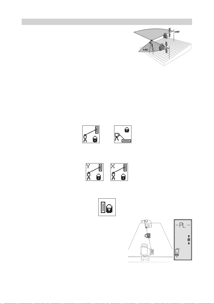
6.2 Automatic PlaneLok Mode
The PlaneLok mode can be activated in horizontal and vertical
automatic and manual mode (in vertical not for GL622IR).
In PlaneLok mode when set up horizontal, the beam will be locked
to a xed elevation point (up to 150 m (490 ft) located on one axis
at each side of the laser.
For keeping vertical alignments xed to a direction point, PlaneLok
can be used in both directions on the Y-axis (GL622N only) or on
the X-axis (function not available for GL622IR).
Note: In every PlaneLok mode the laser continues to servo to the receiver’s signals. Any loss of signal over an
extended period of time (1 minute) causes the laser to go into the HI-alert condition (beam turns off, rotor stops
and a warning message occurs at the LCD. PlaneLok mode can be reactivated after the error message has been
deleted with button 4. Exiting of PlaneLok mode can be done by pressing button 3 (ESC) or any HL760 button.
Horizontal Set Up:
1. Set up the laser over the reference point.
2. Attach the HL760 receiver to a grade rod. Place the receiver at the second point and adjust it to the On-
grade position. The receiver should be permanently mounted at this location and at the desired elevation.
3. Use the sighting guides on the top of the laser to align the laser to the receiver. Turn the laser on the tripod
until it is roughly aligned to the receiver’s position (the alignment range for both axes is +/-40°).
4. Press and release the MENU button at the Standard Display and select PlaneLok (Pic 11).
Pic 11 PlaneLok
horizontal
Pic 12 PlaneLok
vertical
5. When set up horizontally, press and release button 4 to open the PlaneLok submenu; select the desired
PlaneLok axis Y (Pic 13) or X ((Pic 14)- only GL622N/GL622IR) then press button 4 to start PlaneLok.
Note: The laser starts to search for the receiver. A ashing Receiver and Lock symbol appears at the selected
axis and becomes solid when PlaneLok has been completed.
The HL760 display shows a ashing –PL– during the time the
laser is searching and adjusting the beam to the on-grade position.
When PlaneLok is complete, –PL– stops ashing at the HL760
display.
6. Exiting of PlaneLok can be done by pressing button 3 (ESC).
Vertical Set Up (function not available for GL622IR):
1. Set up the laser over the reference point
2. Attach the HL760 receiver (with the vertical adapter) to the next
reference point
3. Press and release the MENU button at the Standard Display and select PlaneLok (Pic 12). With product
GL612N, PlaneLok in X-axis can be started immediately by pressing button 4. With product GL622N press
Pic 13 PlaneLok
Y-Axisp
Pic 14 PlaneLok
X-Axis
mm
10
and release button 4 to open the PlaneLok submenu; select the Y axis (Pic 13) or X-axis (Pic 14) and release
button 4 to start PlaneLok
Note: When used in vertical mode, the receiver has to be placed with the photocell on the bottom side; for
Y-PlaneLok, align the top of the receiver to the top of the laser. The HL760 display shows a ashing – PL
– during the time the laser is searching and adjusting the beam to the on grade position. When PlanLok is
complete, - PL – stops ashing at the HL760 display.
4. Exiting of PlaneLok can be done by pressing button 3 (ESC).
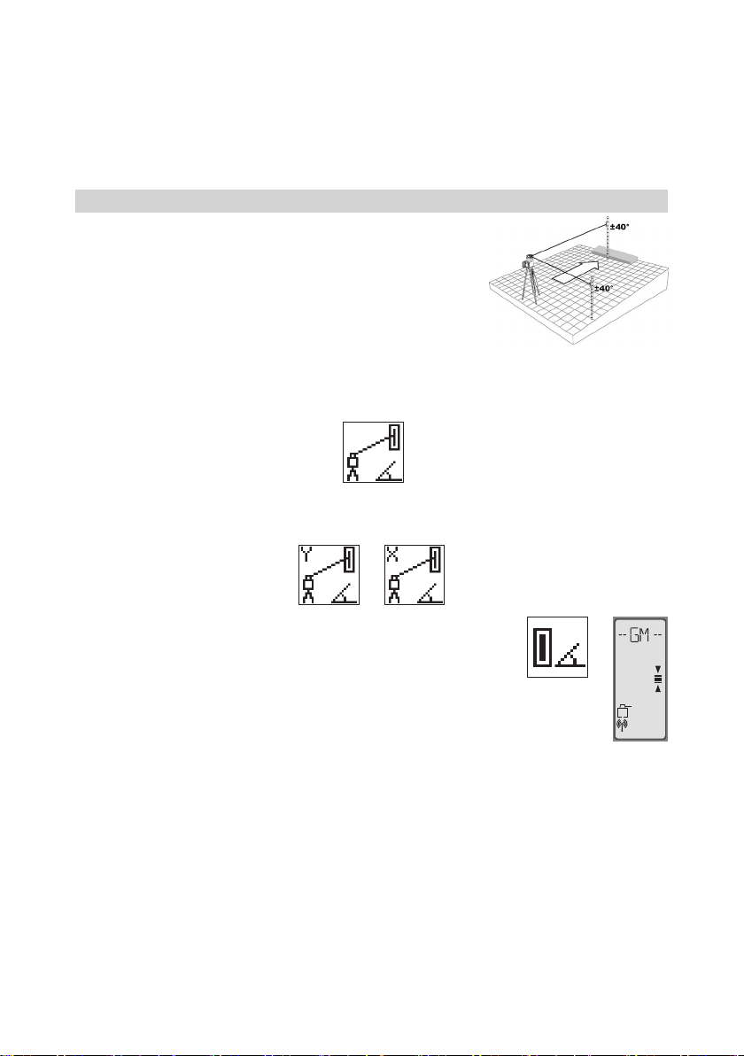
6.3 Automatic Grade Match
The Grade Match mode can be activated in horizontal automatic and
manual mode.
In Grade Match mode, the laser can be used to measure the existing
grade value between two known elevation points (up to 150 m (490 ft)
located on one axis at each side of the laser
1. Set up the laser over the reference point.
2. Attach the HL760 receiver to a grade rod. Check the laser’s elevation
next to the laser then position the receiver at the second point
WITHOUT changing the receiver’s elevation on the rod.
3. Use the sighting guides on the top of the laser to align the laser to the receiver. Turn the laser on the tripod
until it is roughly aligned to the receiver’s position (the alignment range for both axes is +/-40°).
4. Press and release the MENU button at the Standard Display and select Grade Match. (Pic 15)
5. Select the desired Grade Match axis Y (Pic 16) or X (Pic 17; only GL622N / GL622IR) then press button 4
to start Grade Match.
Note: The laser starts to search for the receiver. A ashing Receiver and angle
symbol appears at the selected axis and disappears when Grade Match has
been completed.
While the laser is searching and adjusting the beam to the on-grade position, the
HL760 display shows a ashing –GM–.
When Grade Match has been completed, the HL760 goes back to the standard
elevation display. The remote control as well as the laser will display the nal
measured grade value.
Note: If Grade match can’t be completed by checking the limits, the laser comes with an Error message (Grade
Match has Failed) which can be deleted with button 4 (OK). The HL760 goes back to standard elevation
indication.
Pic 15 Grade Match
mm
Pic 16 Grade Match
Y-Axis
Pic 17 Grade Match
X-Axis
11
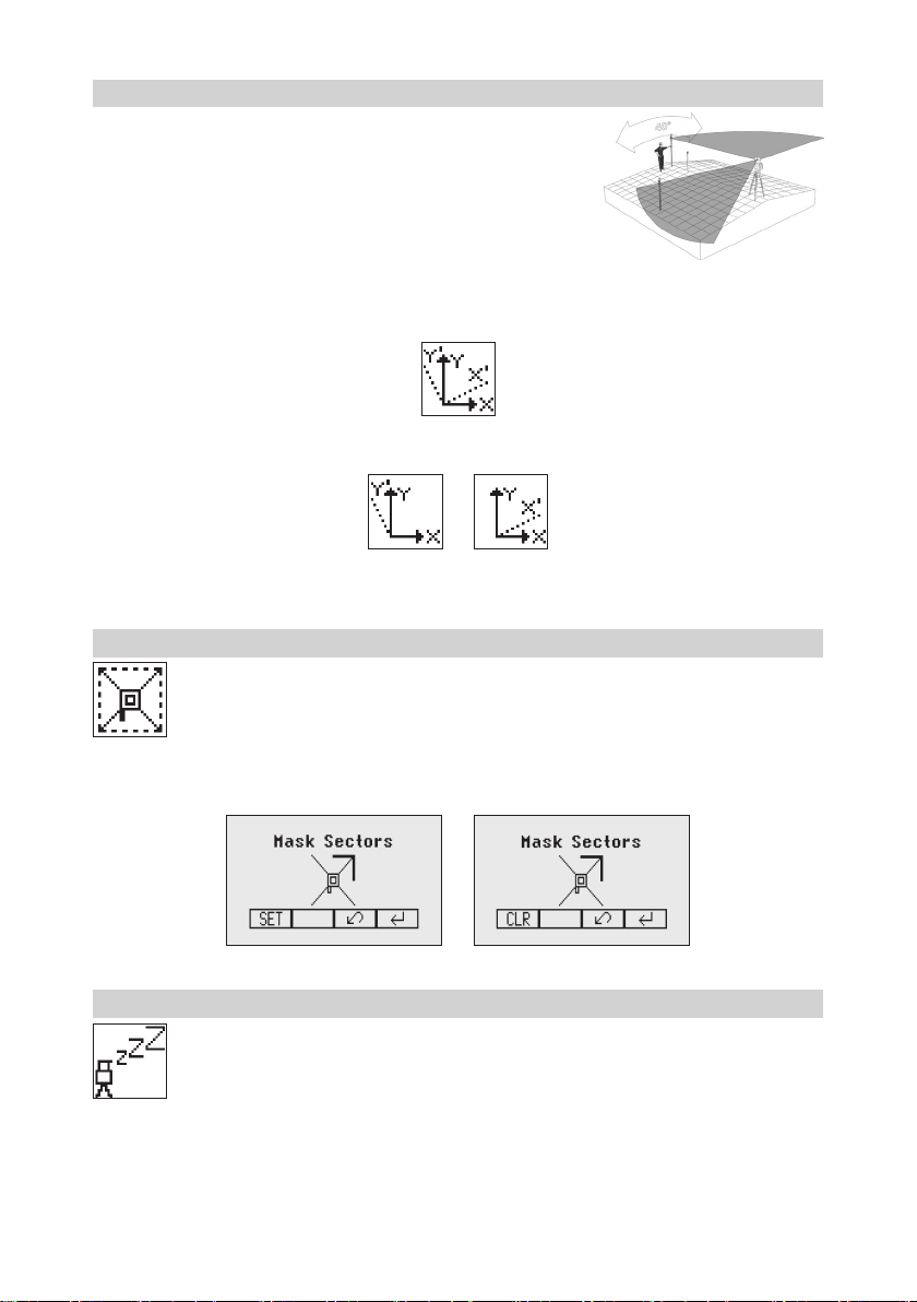
6.4 Automatic Axis Alignment (only GL622N / GL622IR)
Automatic Axis Alignment mode adjusts automatically the direction
the grade axis is pointing to the receiver’s location by an electronically
simulation of rotating the unit on its base to match the hub. Using Axis
Alignment, the laser axis can be aligned to one direction hub (up to 150
m (490 ft) located on one axis at each side of the laser.
1. Set up the laser over the reference point.
2. Place the grade rod with the attached HL760 receiver at the desired
direction hub.
3. Use the sighting guides on the top of the laser to align the laser to the receiver. Turn the laser on the tripod
until it is roughly aligned to the receiver’s position (the alignment range for both axes is +/-40°).
4. Press and release the MENU button at the Standard Display and select Axis Align. (Pic18)
5. Select the desired axis Y (Pic 19) or X (Pic 20) then press button 4 to start Axis Align.
Note: Adjusting the receiver into the beam before starting the automatic Axis Alignment reduces the time
needed for nishing the alignment.
6.5 Mask mode
Select the Mask icon (Pic 21) and press and release button 4 to open the Mask setting menu.
Depending on which side or corner the beam should be turned off, the required sector can be
selected. Press and release the buttons 5 to 8 for moving a short ashing line around the mask
mode symbol. For selecting the sector where the bar is ashing, press and release button 1 (SET).
After setting the rst sector, button 1 changes to show CLR which offeres the capability of deleting
the selected mask sector again. Use button 5 to 8 to move the ashing bar to other required areas
and repeat the setting process. When all areas have been set, press button 4 to store the mask
sector selection until the unit will be turned off.
Note: The unit always powers up with the mask mode deactivated (default).
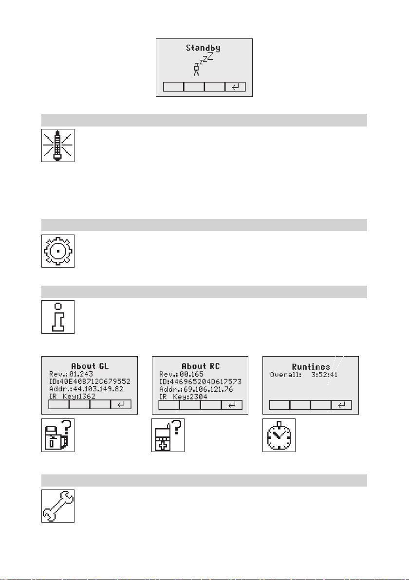
6.6 Activating/Deactivating Standby mode
Press and release the MENU button at the Standard Display and select Standby (Pic 22).
Pressing and releasing button 4 activates the Standby mode.
The self-leveling will be stopped and the beam will be turned off while the HI alert is still active.
The display shows the standby symbol and the Level/Standby LED ashes red every 5 seconds.
To deactivate Standby mode and restore full operation of the laser, press and release button 4.
Pic 18 Axis
Alignment horizontal
Pic 19 Axis
Alignment Y Axis
Pic 20 Axis
Alignment X-Axis
Pic 21
Mask Mode
Pic 22
Standby
12
6.7 Start Reference Check
When working during temperature changes and over long distances the product requires a frequent
reference check to maintain accuracy and avoid errors caused by drift. The transmitter will do an
automatic upon start up and after 20 minutes of operation. It will repeat the reference check every
60 minutes and when there is a 5°C (9°F) change within the product. When carrying out work where
accuracy is paramount it is advised to manually prompt a reference check at regular intervals.
Press and release the MENU button at the Standard Display and select Reference Check
(Pic 23).
Pressing and releasing button 4 starts the Reference Check considering the current temperature inside the
housing. While the rotor checks the correct position the rotation will be stopped.
Note: A grade value has to be entered before the unit starts the reference check.
6.8 Setting Menu
Press and release the MENU button at the Standard Display and select Settings (Pic 24).
Press and release button 4 to open the Setting Menu; select the desired function then press button
4 to open the selected submenu function OR start the selected function.
Please see the Setting Menu details at the end of the user guide.
6.9 Info
Press and release the MENU button at the Standard Display and select Info (Pic 25).
Buttons 6/7 can be used to toggle between GL, RC and Runtime.
Press and release button 4 to conrm the selection.
The GL/RC information (software version, ID, etc.) or the runtime of the GL will be displayed.
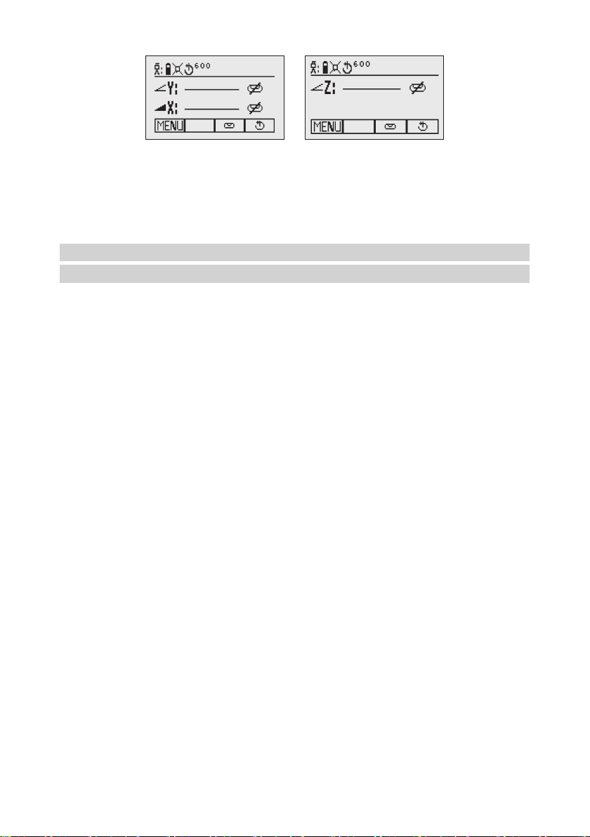
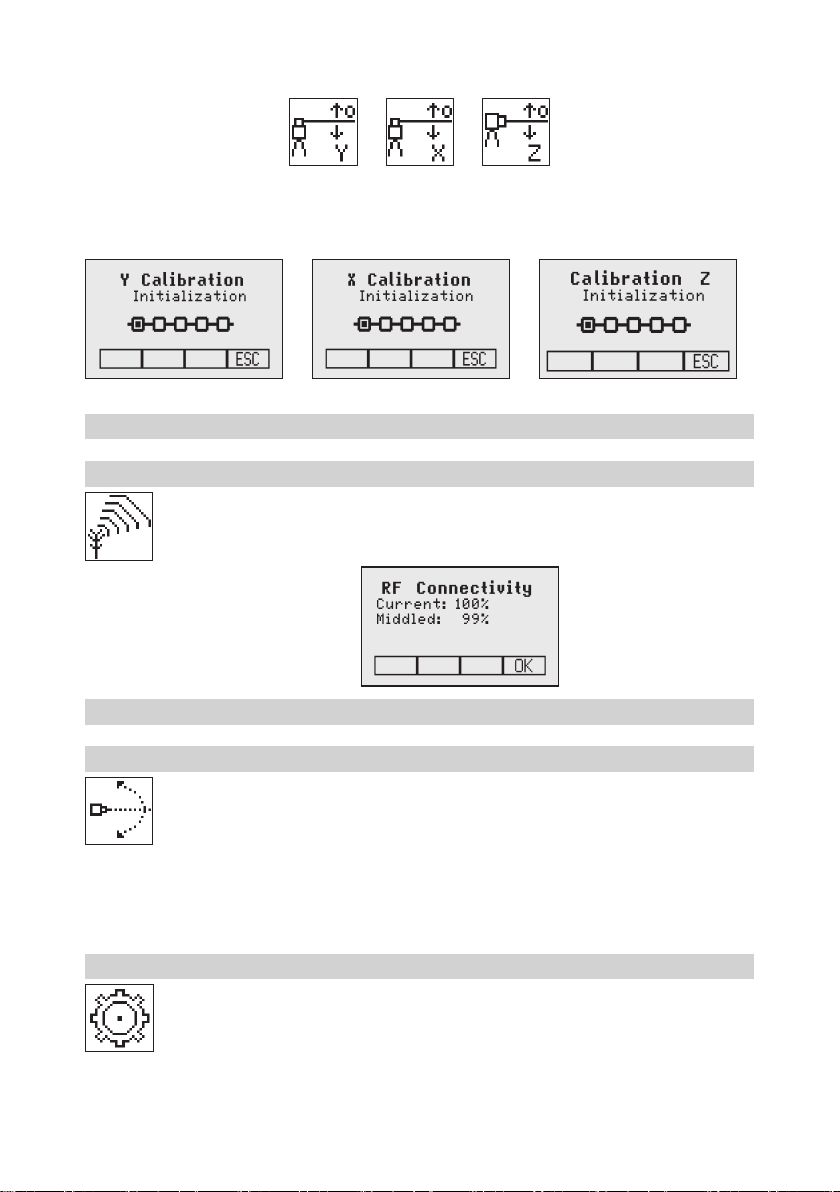
6.10 Service
Press and release the MENU button at the Standard Display and select Service (Pic 29). Buttons
6/7 can be used to toggle between Calibration Y and Calibration X OR Calibration Z (not
GL622IR) when set up vertically.
Pic 23
Reference
Check
Pic 24 Settings
Pic 25 Info
Pic 26 Info GL Pic 27 Info RC
Pic 28 Runtimes
Pic 29
Service
13
Press and release button 4 to conrm the selection. The calibration at the selected axis starts the eld calibration
procedure.
6.11 RC602N Service menu:
6.11.1 RF Connectivity
Press and release button 4 to get a status of the current Radio connectivity (Pic 33).
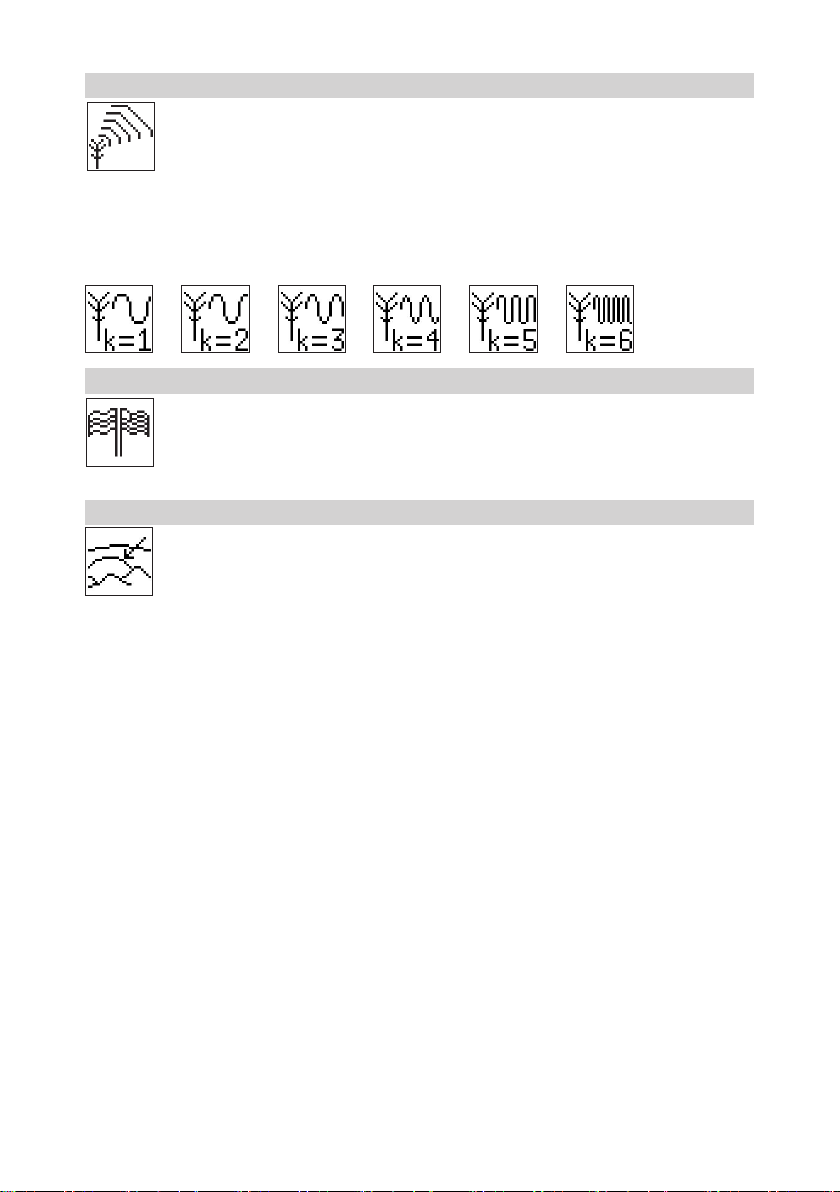
7 Special Features - Vertical Setup
7.1 Line Scan
Line Scan (Pic 34) centers the rotor horizontally and can be used to align the plumb beam to
a desired horizontal position. Press and release the MENU button at the Standard Display and
select Line Scan. Pressing and releasing button 4 activates the Line Scan mode while the rotor
checks the limits of the X- axis and stops at the center position.
Pressing button 3 (ESC) stops the movement and changes the unit into manual mode.
Corrections up and down can be done using button 5/8; for left/right corrections use button 6/7.
Press and release the manual button to change the unit back to full automatic mode.
8 Settings
Press and release the MENU button at the Standard Display and select Settings (Pic 35).
Press and release button 4 to open the Setting Menu; select the desired function then press button
4 to open the selected submenu function OR start the selected function.
The Setting Menu offers the following functions:
Pic 30
Calibration Y
Pic 31
Calibration X
Pic 32
Calibration Z
Pic 33 Radio
Connectivity
Pic 34
Line Scan
Pic 35
Settings
14
Pairing
Grade Entry Grade Display Sensitivity
HI-Alert
User Name Set Password Password On/Off RF-Channel
Select
Language
Position Info
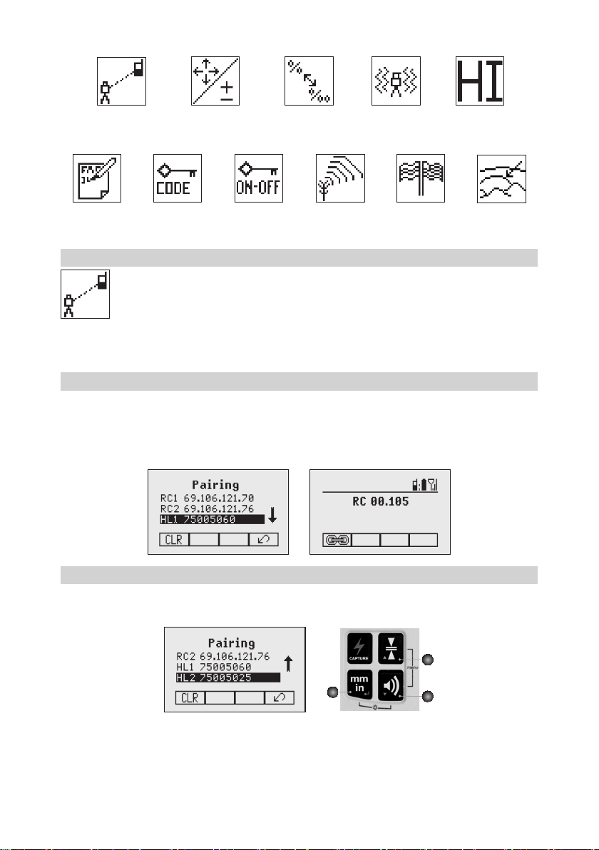
8.1 Pairing
Pairing is needed to couple different devices with the laser. The laser is able to communicate with
several numbers of other radio network participants and pairing is the process to link these to each
other. Buying the laser all devices should be paired but for some reasons this may not be true
or the pairing has been lost. So you can pair the devices as described in the following sections.
Note: Make sure that pairing mode is selected only at one transmitter which is within the radio range of the
remote during a pairing request. Otherwise pairing procedure can be confused.
8.2 Pairing the laser with remote control
Start with the Laser. When in menu Settings (Pic 35), press and release button 4 to open the pairing menu
(Pic 47). The display shows the currently paired units (up to two remotes). Make sure at least one RC slot is
free for the remote to be paired. If no free RC slot is available, choose one of them and delete it using button
1 (CLR). Press button 2 to start the pairing process. Continue with the remote choosing the symbol pairing
(Pic 47); the pairing starts automatically. After successful pairing, the laser display shows the ID of the remote
in the pairing list.
8.3 Pairing the laser with receiver HL760
To pair the transmitter and the receiver select Settings and press and release button 4 to open the Pairing
menu (Pic 47). The display shows the currently paired units (up to 2 receivers). If already 2 receivers have
been paired, one or both of them have to be deleted using button 1 (CLR).
A
B
C
Next, turn on the receiver then press and hold the Deadband (A) and the Audio (B) buttons for two seconds.
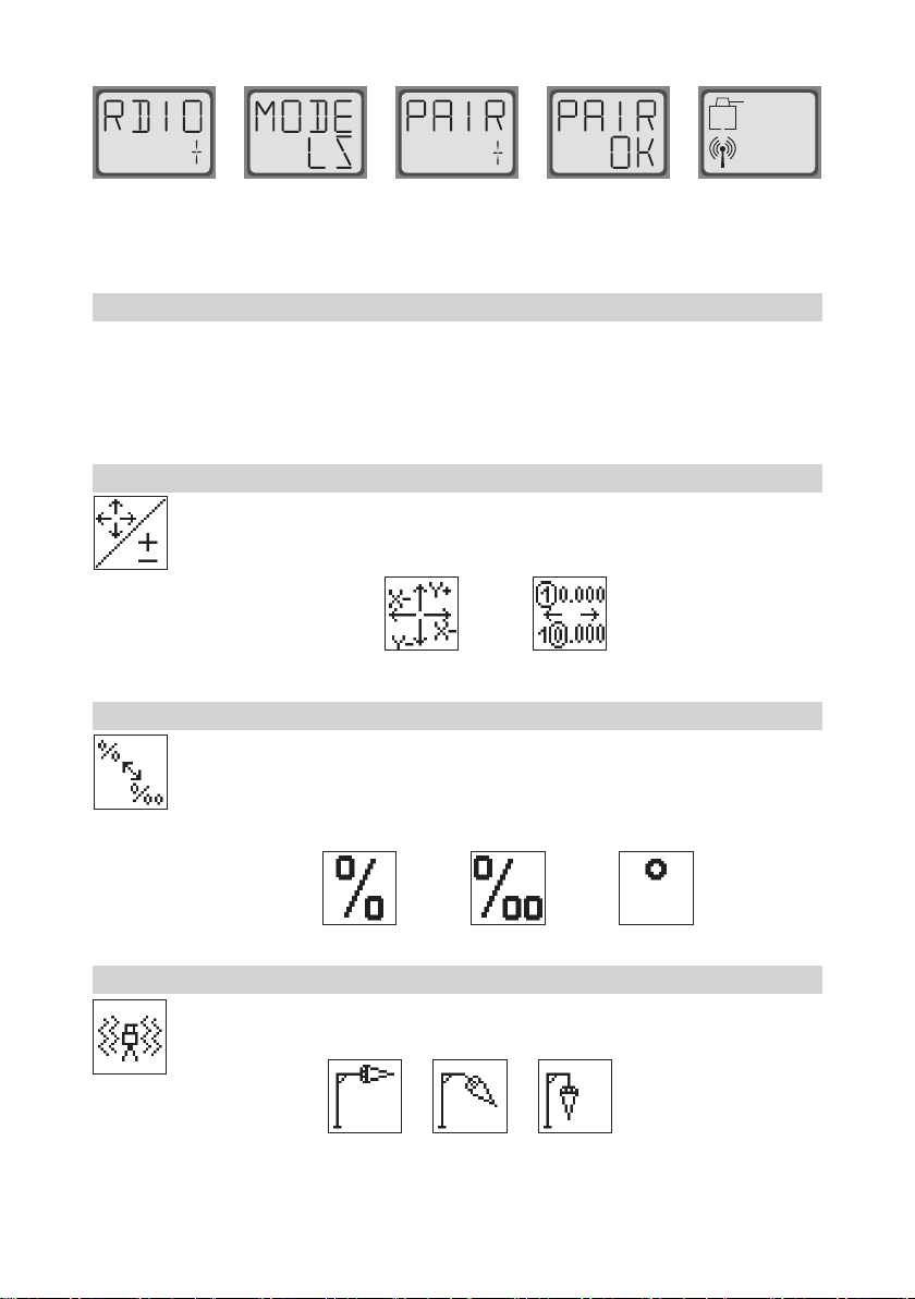
After two seconds the display shows MENU rst, then RDIO.
Press and release the Units (C) button – display shows the current radio mode.
Pic 47 Pairing
15
If not already set to LS, press Units button and then press Deadband or Audio button until LS is displayed.
Press Units button again to enter selection. Press and release the Audio button – display shows PAIR. Press
the Units button again – the display shows PAIR and a rotating bar. After completing PAIR, OK will be displayed.
The GL6X2N pairs now automatically with the new receiver. Press and release the Power button two times to
exit the menu. A laser symbol is lit to conrm the receiver can communicate with the laser.
8.4 Pairing the laser with the signal transporter (ST802/ST805)
Make sure the ST802/ST805 is switched off. Start with the Laser. When in menu Settings (Pic 35), press and
release button 4 to open the pairing menu (Pic 47). The display shows the currently paired units (one signal
transporter max). Make sure the ST slot is free for the signal transporter to be paired. If the slot is not free,
choose the ST slot and delete it using button 1 (CLR). Press button 2 to start the pairing process. Switch on
the signal transporter. The signal transporter pairs automatically with the laser. If the pairing was successful
the address or ID of the paired ST is shown in the pairing list; also the signal transporter shows a solid blinking
yellow status LED.
8.5 Grade Entry
Select the Grade Entry icon (Pic 48) and press and release button 4 to open the Grade Entry menu.
Buttons 6/7 can be used to toggle between Step and Go (Pic 49) and Digit Select (Pic 50).
Press and release button 4 to conrm the selection.
Pic 49
Step and Go
Pic 50
Digit Select
8.6 Grade Display
Select the Grade Display icon (Pic 52) and press and release button 4 to open the Grade Display
menu.
The desired Grade Display Mode (Percent (Pic 52)/ Permille (Pic 53)/Degree (Pic 54)) can be
selected using the buttons 6/7. Press and release button 4 to conrm the selected display mode.
8.7 Sensitivity Selection
Select the Sensitivity icon and press and release button 4 to open the Sensitivity menu (Pic 56).
The desired Sensitivity: Low (Pic 56), Mid (Pic 57) (Default) and High (Pic 58)) can be selected
using the buttons 6/7. Press and release button 4 to conrm the selected Sensitivity.
Pic 48
Grade Entry
Pic 52
Grade Display
Pic 53
Per mill
Pic 52
Percent
Pic 54
Degree
Pic 56
Sensitivity
Pic 56 Low
Pic 57 Mid
Pic 58 High
16
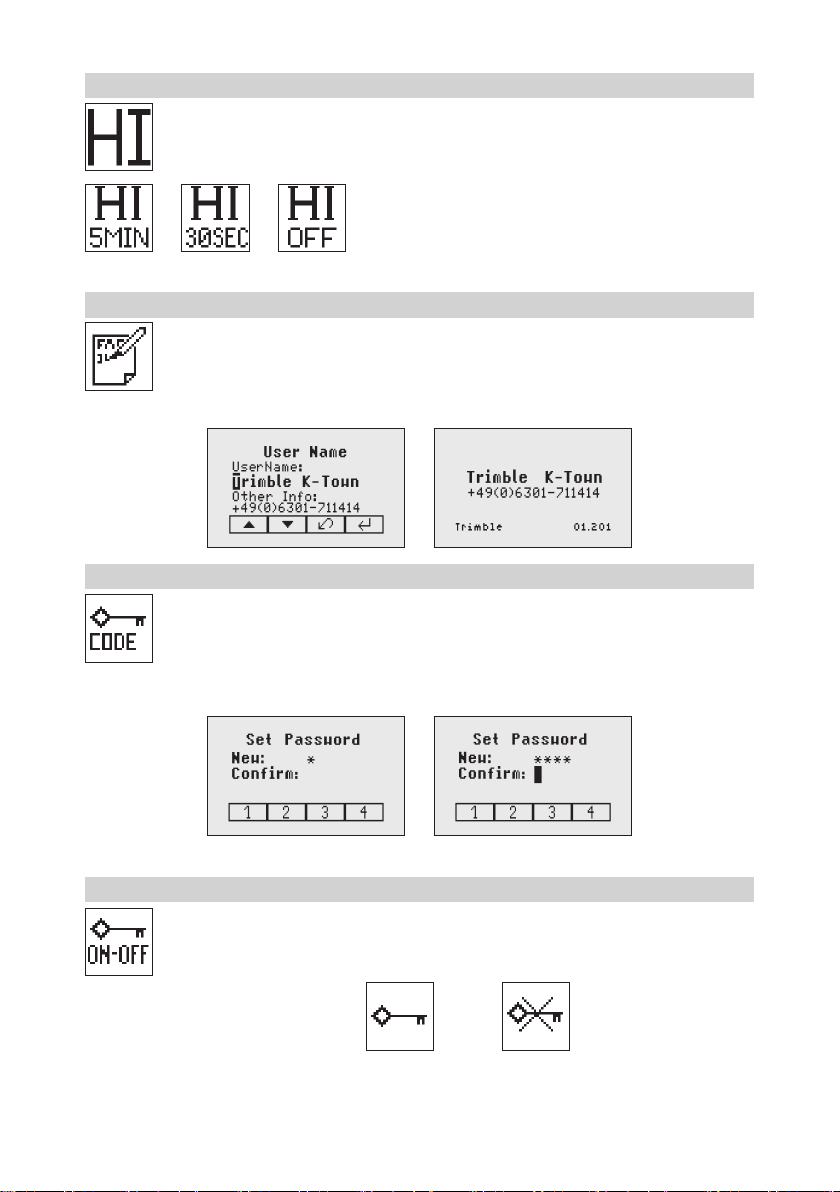
8.8 HI-alert Selection
Select the HI icon (Pic 59) and press and release button 4 to open the HI-alert menu. The desired
HI-alert: 5 min.(Pic 60); Default), 30 seconds (Pic 61) and HI-Off (Pic 62) can be selected using
the buttons 6/7. Press and release button 4 to conrm the selected HI-alert.
8.9 User Name
Select the User name icon (Pic 64) and press and release button 4 to open the User name menu.
One row for typing names in big font (15) and one row in small font (18) for letters or numbers
are available. Button 5 and 8 can be used to toggle between both rows. Changing the characters
can be done using the buttons 1 and 2. Press and release button 4 to conrm the selected user
name. The display falls back to the main menu. Any time the unit will be powered up, the User
info will be displayed for couple seconds.
8.10 Set Password
“Set password” can be used to dene a key that is requested during the unit powering up. This
can prevent the unauthorized usage of the transmitter. Enter Menu -> Settings -> Set Password.
Select the Set Password icon (Pic 65) and press and release button 4 to open the Password
menu. Use Button 1 to 8 to type in a password containing of 4 digits and repeat the password at
the second row. (Pic 66) Press and release button 4 to store the selected password; unit falls
back to the standard menu. After powering up the unit, the standard display comes up if the correct
password has been entered, otherwise the unit turns off automatically.
8.11 Password On/Off
Select the Set Password ON-Off icon (Pic 68) and press and release button 4 to open the Password
menu. Buttons 6/7 can be used to toggle between Password On (Pic 68) and Password Off (Pic
69) if a Password has been entered before. Press and release button 4 to conrm the selection.
Pic 68 Password
On
Pic 69 Password
Off
Pic 59 Hi Alert
Pic 60 HI-alert
5 minutes
Pic 61 HI-alert
30 seconds
Pic 62 HI-alert
OFF
Pic 64
User Name
Pic 65 Set
Password
Pic 65 Set Password
Pic 66 Conrm Password
Pic 68 Password
On/Off
17
8.12 Radio (RF) Channel
In the RF Channel menu the user can change the radio channel. This may help to overcome some
radio connectivity issues based on heavy radio trafc at the job site. In the menu “Settings” (Pic
35) select the RF Channel icon (Pic 71) and press and release button 4 to open the Radio Channel
menu (Pic 71). The RF channel selection dialog contains six radio channels. Choose one channel
and press and release button 4 to conrm the selected radio channel.
Note: After changing the RF channel, the RC, HL and ST needs to be paired again.
Note: To achieve the best radio performance, it is recommended to use the products in a height of app. 1m
using a tripod or similar items.
8.13 Select Language
Select the Language icon (Pic 72) and press and release button 4 to open the Language menu.
Use button 5 to 8 to select the required local language (EN, DE, IT, FR, ES, PT, NL, DA, NO,
SV, FI, PL, TR, CZ).Press and release button 4 to store the selected Language; unit falls back
to the standard menu.
8.14 Position Info
When working with high grade values (> 10%) or at extreme the product requires the position info to
maintain accuracy and avoid errors caused by different gravity. The user has the chance to provide
the position info of the job site to the product. This is the degree of latitude as well as the altitude.
Choose Menu Settings (Pic 35) and navigate to the sub menu Position Info (Pic 73). Press button 4 to activate
the submenu. With buttons 1 and 2 the different values can be increased/decreased. Also ‘+’ or ‘-‘ for the
latitude can be changed with buttons 1 and 2. With buttons 5, 6, 7 and 8 the cursor position can be changed.
Note: To restore the default value scroll down with arrow buttons 5 or 8 to ‘Default position’. Press button 1
(‘Set’); the unit will change the settings to the default values. Press button 4 to conrm the change.
Pic 71
RF Channel
Pic 72
Language
Pic 73
Position Info
18
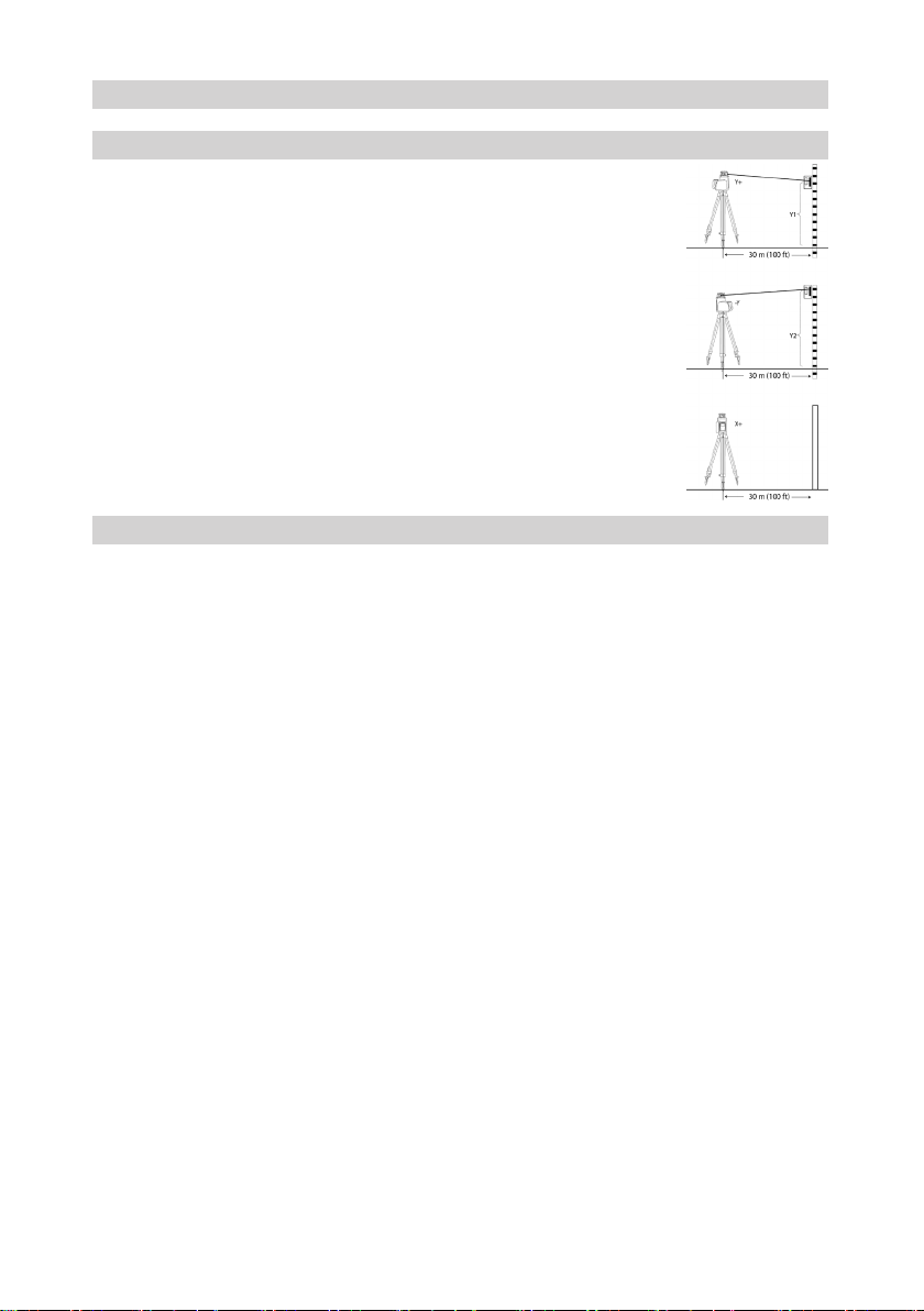
9 CALIBRATION
9.1 Checking Calibration of the Y- and X-Axes
1. Set up the laser 30 m (100 ft) from a wall and allow it to level.
2. Set the grade to 0.000% in both axes.
3. Raise/lower the receiver until you get an on-grade reading for the +Y axis. Using
the on-grade marking notch as a reference, make a mark on the wall.
Note: For increased precision, use the super ne-sensitivity setting (1.0 mm/ 1/16
in.) on the receiver.
4. Rotate the laser 180° (-Y axis toward the wall) and allow the laser to re-level.
5. Raise/lower the receiver until you get an on-grade reading for the –Y/axis. Using the
on-grade marking notch as a reference, make a mark on the wall.
6. Measure the difference between the two marks. If they differ more than 3 mm at 30
m (1/8 inch at 100 feet), the laser needs calibrating.
7. After checking the Y-axis, rotate the laser 90°. Repeat the above starting with the
+ X axis facing the wall.
9.2 Checking Calibration of the Z-(vertical) Axis (not available for GL622IR)
To check vertical calibration, you need a plumb bob with at least 10m (30ft) of string.
1. Suspend the plumb bob in front of a house i.e., attached to a window frame whose window height is at least
10m (30ft).
2. Set up the laser in vertical so that the laser beam strikes the receiver’s on-grade position at the top of the string.
3. Look for any deviation using the receiver from the top of the string to the bottom of it. If the deviation is more
than 1mm (<1/16 in.), the vertical axis needs calibrating.

19
10 Troubleshooting
Any error message can be deleted with a short press of button 4 (OK). The table shows the related description
and possible solutions. The next service center should be contacted if a different error message as shown at
the table will be displayed.
Error codes Description Solution
21 Temporary EEprom problem Repeat pairing and re-enter the
customer settings
120 HI alert - Unit Heigt changed Check laser beam elevation after
deleting the HI alert
130 Mechanical Limit during Axis
Alignment, Grade Match or Spot
Match
Re-align the closer to the
alignment point; check if existing
slope is above +/-25%
131 Rake Angle Limit Re-align the unit closer to the
alignment point
140 Laser beam blocked Make sure there are no
obstacles between the
transmitter and the HL760
141 Time Out - Function could not be
completed in the allowed time
Check radio operating range/
connection; check stable laser
setup
150 No receiver - Receiver not
available for single axis
automatic function
Make sure the receiver is on and
paired
152 No receiver - The laser searched
for the receiver but could not
nd it
Check the operating range for
auto function and restart the auto
alignment
153 Lost Receiver - The laser
searched and found the receiver
but then lost it
Check the operating range for
auto function and restart the auto
alignment
160 X or Y level sensor defect Contact service center
20
11 PROTECTING THE UNIT
Do not expose the unit to extreme temperatures or temperature changes (do not leave inside the car). The
unit is very robust and can resist damage if dropped even from tripod height. Before continuing your work,
always check the leveling accuracy. See Checking Calibration section. The laser is water proof and can be
used indoors and outdoors.
12 CLEANING AND MAINTENANCE
Dirt and water on the glass parts of laser or prism will inuence beam quality and operating range considerably.
Clean with cotton swabs. Remove dirt on the housing with a lint-free, warm, wet and smooth cloth. Do not use
harsh cleansers or solvents. Allow the unit to air dry after cleaning it.
13 PROTECTING THE ENVIRONMENT
The unit, accessories and packaging ought to be recycled. All plastic parts are marked for recycling according
to material type.
Do not throw used batteries into the garbage, water or re. Remove them in compliance with
environmental requirements.
Notice to Our European Union Customers
For product recycling instructions and more information, please go to:
http://www.trimble.com/Corporate/Environmental_Compliance.aspx
Instructions for Return to ERFC:
•WEEE is to be shipped to the ERFC, clearly stating WEEE on the delivery note and / or packaging
•Specic product number and serial number information is not required
•Additional return authorisation from Trimble Support is not required
•Delivery Address:
Trimble Europe B.V. WEEE Recycling
C/O Menlo logistics
Gate 19 to 26
Meerheide 43
5521 DZ
Eersel
The Netherlands
Conrmation of receipt of the returned WEEE will not be provided by the ERFC
14 Warranty
Trimble warrants the GL622N/GL612N/GL622IR to be free of defects in material and workmanship for a period
of 5 years. Trimble or its authorized service center will repair or replace, at its option, any defective part, or
the entire product, for which notice has been given during the warranty period. If required, travel and per diem
expenses to and from the place where repairs are made will be charged to the customer at the prevailing
rates. Customers should send the product to Trimble Inc. or the nearest authorized service center for warranty
repairs or exchange, freight prepaid. Any evidence of negligent, abnormal use, accident, or any attempt to
repair the product by other than factory-authorized personnel using Trimble certied or recommended parts,
automatically voids the warranty. Special precautions have been taken to ensure the calibration of the laser;
however, calibration is not covered by this warranty. Maintenance of the calibration is the responsibility of
the user. The foregoing states the entire liability of Trimble regarding the purchase and use of its equipment.
Trimble will not be held responsible for any consequential loss or damage of any kind. This warranty is in lieu
of all other warranties, except as set forth above, including any implied warranty merchantability of tness for
a particular purpose, are hereby disclaimed.
This warranty is in lieu of all other warranties, expressed or implied.

21
15 TECHNICAL DATA
15.1 GL622N/GL612N/GL622IR
Leveling accuracy
1,3
: ± 0.5 mm/10 m, 1/16“ @ 100 ft, 10 arc seconds
Grade accuracy
1,3
: ± 1.0 mm/10 m, 1/8“ @ 100 ft, 20 arc seconds
Grade temperature drift sensitivity: ± 0,3 mm / 10 m / 1°C; 1/16” @ 310 ft. @ 1°F
Rotation: 300, 600, 750 rpm
Operational area
1,2
: appr. 400 m (1300 feet) radius with detector
Laser type: 639 nm (GL622IR: typ. 830nm)
Laser class: class 2 (GL622IR: class 1)
Self-leveling range: appr. ± 14°
Grade range (Y, X-GL622N): ± 25% both axes (not simultaneously)
Leveling indicators: LCD indications and LED ashes
Radio range (HL760)
1,2,4
: up to 150 m (490 ft)
Power source: 4 x 1,5 V D alkaline batteries or NiMH battery pack
Battery life
1
: 35 hours NiMH (GL622IR: 40 hours NiMH)
Operating temp.: -20°C to 50°C (-4°F to 122°F)
Storage temp.: -20°C to 70°C (-4°F to 158°F)
Tripod attachments: 5/8 x 11 horizontally and vertically
Dust and Water proof: IP67
Weight: 3.1 kg (6.8 lbs)
Low voltage indication: LCD battery indicator
Low voltage disconnection: unit shuts off
15.2 Remote Control RC602N
Radio Operating range
1,2,4
: up to 150 m (490 ft)
Power source: 2 x 1.5V AA alkaline batteries
Battery life
1
: 130 hours
Dust and Water proof: IP66
Weight: 0.26 kg (0.4 lbs)
1) at 21°Celsius
2) under optimal atmospheric circumstances
3) along the axis
4) Heigt of instruments 1m (e.g. with tripod)
16 DECLARATION OF CONFORMITY
We
Trimble Kaiserslautern GmbH
Declare under our sole responsibility that the products
GL622N/GL612N/GL622IR and RC602N
To which this declaration relates is in conformity with the following standards:
EN 50371:2002, EN 60825-1:2014, ETSI EN 300328 V1.7.1:2006, ETSI EN 301489-1 V1.9.2:2011,
ETSI EN 301489-3 V1.4.1:2002
following the provisions of directive R&TTE 1999/5/EC.
The managing director

22
17 ELECTRO-MAGNETIC COMPATIBILITY
Compliance statement (part 15.19) This device complies with part 15 of the FCC Rules and Industry
Canada licence-exempt RSS standard(s). Operation is subject to the following two conditions: (1) this
device may not cause harmful interference, and (2) this device must accept any interference received,
including interference that may cause undesired operation. Warning (part 15.21) Changes or modications
not expressly approved by the party responsible for compliance could void the user’s authority to operate
the equipment. This in particular is applicable for the antenna which has been delivered with the GL622N/
GL612N/GL622IR) and RC602N Under Industry Canada regulations, this radio transmitter may only operate
using an antenna of a type and maximum (or lesser) gain approved for the transmitter by Industry Canada.
To reduce potential radio interference to other users, the antenna type and its gain should be so chosen
that the equivalent isotropically radiated power (e.i.r.p.) is not more than that necessary for succesful
communication. 17 ELECTRO-MAGNETIC COMPATIBILITY
Compliance statement (part 15.19) This device complies with part 15 of the FCC Rules and Industry
Canada licence-exempt RSS standard(s). Operation is subject to the following two conditions: (1) this
device may not cause harmful interference, and (2) this device must accept any interference received,
including interference that may cause undesired operation. Warning (part 15.21) Changes or modications
not expressly approved by the party responsible for compliance could void the user’s authority to operate
the equipment. This in particular is applicable for the antenna which has been delivered with the GL622N/
GL612N/GL622IR) and RC602N Under Industry Canada regulations, this radio transmitter may only operate
using an antenna of a type and maximum (or lesser) gain approved for the transmitter by Industry Canada.
To reduce potential radio interference to other users, the antenna type and its gain should be so chosen
that the equivalent isotropically radiated power (e.i.r.p.) is not more than that necessary for succesful
communication.