Loading ...
Loading ...
-3-
Do not overreach. Keep
proper footing and balance
at all times. This enables better control of the
power tool in unexpected situations.
Always maintain control of
tool power switch. Some
cutting applications require repositioning of
your hands. Always ensure that one hand is
in control of the power switch.
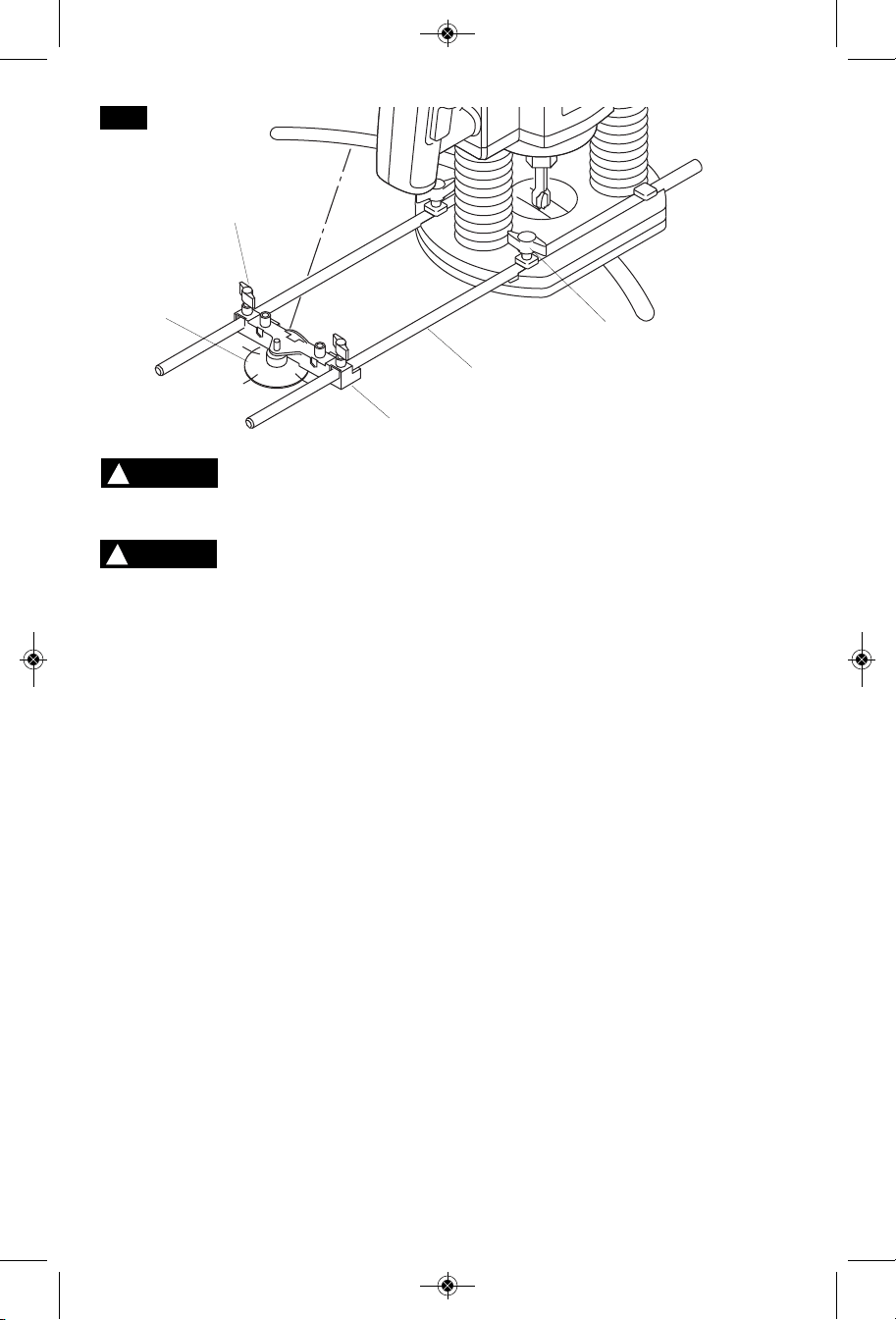
ASSEMBLY FOR USE AS
A CIRCLE GUIDE
To reassemble the deluxe router guide for use
as a circle guide (or arc guide), follow these
steps: (Fig. 3)
1. Loosen rear wing knobs (I) and fine
adjustment knob (K), spacer, and indicator
(L) and remove these parts from guide rods
(F).
2. Remove springs (H) from guide rods.
3. Loosen front wing knobs (G) and guide
base (E) and remove from the guide rods.
4. Reinstall fine adjustment guide (J) onto
guide rods (F) rotated 180 degrees from
normal position so that circle guide hole
faces away from the router.
5. Insert guide rods (F) into router base. For
maximum stability, make sure each rod
goes through both holes and protrudes out
the other side of the router base. (At a
minimum, the rods must be inserted far
enough into the router base that they are
both supported from below at a point
beyond the fastener on the router.)
6. Securely fasten the router to the rods by
tightening the thumbscrews (N).
(Depending on the router model, another
set of wing knobs (O) may be used instead
of the knurled thumbscrews.) The largest
circles and arcs can be made when the
guide rods enter the side of the router
where the thumbscrews (or wing knobs)
are located.
7. Mark the workpiece at the center of the
desired circle.
8. Using the centering slots on the edge of the
pivot plate (P), center the pivot plate on the
center mark and attach to the workpiece
with several strips of strong tape placed
over the pivot plate in a crisscross pattern.
9. Place fine adjustment guide (J) on pivot
plate (P) so that the hole in guide (J) fits
over the steel pin.
10.Adjust the position of the rods and router as
necessary to achieve the desired radius of
the circle or arc, then securely tighten wing
knobs (I).
ATTACHING THE DUST
EXTRACTION HOOD
To attach the dust extraction hood (M): (Fig. 4)
1. Remove the two guide plates (D) by
loosening the four screws and lifting the two
guide plate assemblies off the top of the
guide base.
2. Remove the nuts (C) from the two center
screws.
3. Reattach the guide plates using only their
outside screws.
4. Insert the nuts (C) into the hex cavities in the
dust extraction hood.
F
IG. 3
J
P
I
F
O
WARNING
!
WARNING
!
BM 2610998756 09-11:BM 2610998756 09-11 9/22/11 8:03 AM Page 3
Loading ...
Loading ...
Loading ...