
Read these instructions carefully before installation.
Keep this manual in a handy place for future reference.
This manual should be left with the equipment owner.
Lire soigneusement ces instructions avant l’installation.
Conserver ce manuel à portée de main pour référence
ultérieure.
Ce manuel doit être donné au propriétaire de l’équipement.
Lea cuidadosamente estas instrucciones antes de instalar.
Guarde este manual en un lugar a mano para leer en caso
de tener alguna duda.
Este manual debe permanecer con el propietario del
equipo.
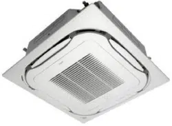
MODELS
Ceiling Mounted Cassette type (Round Flow with Sensing Panel)
FCQ18TAVJU
FCQ24TAVJU
FCQ30TAVJU
FCQ36TAVJU
FCQ42TAVJU
FCQ48TAVJU
INSTALLATION MANUAL
SPLIT SYSTEM Air Conditioners
English
Français
Español
00_CV_3P161684-9U.indd 1 5/9/2018 14:05:06
i
English
CONTENTS
1. SAFETY CONSIDERATIONS ................................[i] [ii]
2.
BEFORE INSTALLATION ............................................ 1
3. SELECTION OF INSTALLATION LOCATION .............. 2
4.
PREPARATION BEFORE INSTALLATION .................. 4
5. INSTALLATION OF INDOOR UNIT ............................. 4
6.
REFRIGERANT PIPING WORK .................................. 6
7.
DRAIN PIPING WORK ................................................ 7
8.
ELECTRIC WIRING WORK ....................................... 10
9.
MOUNTING DECORATION PANEL .......................... 14
10. FIELD SETTING ........................................................ 15
11. TEST OPERATION .................................................... 16
1. SAFETY CONSIDERATIONS
Read these SAFETY CONSIDERATIONS for Installation
carefully before installing air conditioning equipment. After
completing the installation, make sure that the unit operates
properly during the startup operation.
Instruct the customer on how to operate and maintain the
unit. Inform customers that they should store this Installation
Manual with the Operation Manual for future reference.
Always use a licensed installer or contractor to install this
product. Improper installation can result in water or refrigerant
leakage, electrical shock, re, or explosion.
Meanings of DANGER, WARNING, CAUTION, and NOTE
Symbols:
DANGER ............ Indicates an imminently haz-
ardous situation which, if not
avoided, will result in death or
serious injury.
WARNING .......... Indicates a potentially haz-
ardous situation which, if not
avoided, could result in death
or serious injury.
CAUTION ........... Indicates a potentially haz-
ardous situation which, if not
avoided, may result in minor
or moderate injury. It may
also be used to alert against
unsafe practices.
NOTE .................. Indicates situations that may
result in equipment or prop-
erty damage accidents only.
DANGER
• Refrigerant gas is heavier than air and replaces oxy-
gen. A massive leak can lead to oxygen depletion,
especially in basements, and an asphyxiation hazard
could occur leading to serious injury or death.
• Do not ground units to water pipes, gas pipes, tele-
phone wires, or lightning rods as incomplete ground-
ing can cause a severe shock hazard resulting in
severe injury or death. Additionally, grounding to gas
pipes could cause a gas leak and potential explosion
causing severe injury or death.
• If refrigerant gas leaks during installation, ventilate
the area immediately. Refrigerant gas may produce
toxicgasifitcomesincontactwithre.Exposureto
this gas could cause severe injury or death.
• After completing the installation work, check that the
refrigerant gas does not leak throughout the system.
• Donotinstallunitinanareawhereammablemate-
rials are present due to risk of explosions that can
cause serious injury or death.
• Safely dispose of all packing and transportation
materials in accordance with federal/state/local laws
or ordinances. Packing materials such as nails and
other metal or wood parts, including plastic packing
materials used for transportation, may cause injuries
or death by suffocation.
WARNING
• Onlyqualiedpersonnelmustcarryouttheinstalla-
tion work. Installation must be done in accordance
with this installation manual. Improper installation
mayresultinwaterleakage,electricshock,orre.
• When installing the unit in a small room, take mea-
sures to keep the refrigerant concentration from ex-
ceeding allowable safety limits. Excessive refrigerant
leaks, in the event of an accident in a closed ambient
space,canleadtooxygendeciency.
• Useonlyspeciedaccessoriesandpartsforinstalla-
tionwork.Failuretousespeciedpartsmayresultin
waterleakage,electricshocks,re,ortheunitfalling.
• Install the air conditioner on a foundation strong
enough that it can withstand the weight of the unit. A
foundationofinsufcientstrengthmayresultinthe
unit falling and causing injuries.
• Take into account strong winds, typhoons, or earth-
quakes when installing. Improper installation may
result in the unit falling and causing accidents.
• Make sure that a separate power supply circuit is pro-
vided for this unit and that all electrical work is carried
outbyqualiedpersonnelaccordingtolocal,state
andnationalregulations.Aninsufcientpowersupply
capacity or improper electrical construction may lead
toelectricshocksorre.
• Makesurethatallwiringissecured,thatspecied
wires are used, and that no external forces act on the
terminal connections or wires. Improper connections
orinstallationmayresultinre.
• When wiring, position the wires so that the control box
cover can be securely fastened. Improper positioning
of the control box cover may result in electric shocks,
re,ortheterminalsoverheating.
• Before touching electrical parts, turn off the unit.
SPLIT SYSTEM Air Conditioners Installation Manual
01_EN_3P161684-9U.indd 1 8/8/2018 15:26:45
ii
English
• This equipment can be installed with a Ground-Fault
Circuit Interrupter (GFCI). Although this is a recog-
nized measure for additional protection, with the
grounding system in North America, a dedicated GFCI
is not necessary.
• When installing or relocating the system, keep the
refrigerant circuit free from substances other than the
speciedrefrigerant(R410A)suchasair.Anypres-
ence of air or other foreign substance in the refriger-
ant circuit can cause an abnormal pressure rise or
rupture, resulting in injury.
• Do not change the setting of the protection devices. If
the pressure switch, thermal switch, or other protec-
tion device is shorted and operated forcibly, or parts
otherthanthosespeciedbyDaikinareused,reor
explosion may occur.
CAUTION
• Donottouchtheswitchwithwetngers.Touchinga
switchwithwetngerscancauseelectricshock.
• Do not allow children to play on or around the unit to
prevent injury.
• Do not touch the refrigerant pipes during and imme-
diately after operation as the refrigerant pipes may be
hot or cold, depending on the condition of the refriger-
antowingthroughtherefrigerantpiping,compres-
sor, and other refrigerant cycle parts. Your hands may
suffer burns or frostbite if you touch the refrigerant
pipes. To avoid injury, give the pipes time to return
to normal temperature or, if you must touch them, be
sure to wear proper gloves.
• Heatexchangernsaresharpenoughtocut.Toavoid
injury,weargloveorcoverthenswhenworking
around them.
• Install drain piping to proper drainage. Improper drain
piping may result in water leakage and property dam-
age.
• Insulate piping to prevent condensation.
• Be careful when transporting the product.
• Do not turn off the power supply immediately after
stopping operation. Always wait for at least 5 minutes
before turning off the power supply. Otherwise, water
leakage may occur.
• Do not use a charging cylinder. Using a charging cylin-
der may cause the refrigerant to deteriorate.
• RefrigerantR410Ainthesystemmustbekeptclean,
dry, and tight.
(a) Clean and Dry -- Foreign materials (including min-
eral oils such as SUNISO oil or moisture) should
be prevented from getting into the system.
(b) Tight--R410Adoesnotcontainanychlorine,does
not destroy the ozone layer, and does not reduce
the earth’s protection again harmful ultraviolet
radiation.R410Acancontributetothegreenhouse
effect if it is released. Therefore take proper mea-
sures to check for the tightness of the refrigerant
piping installation. Read the chapter REFRIGER-
ANT PIPING WORK and follow the procedures.
• SinceR410Aisablend,therequiredadditionalrefrig-
erant must be charged in its liquid state. If the refriger-
ant is charged in a gaseous state, its composition can
change and the system will not work properly.
• TheindoorunitisforR410A.Seethecatalogforin-
door models that can be connected. Normal operation
is not possible when connected to other units.
• Handheld remote controller transmitting distance can
be shorter than expected in rooms with electronic
uorescentlamps(inverterorrapidstarttypes).
Installtheindoorunitfarawayfromuorescentlamps
as much as possible.
• Indoor units are for indoor installation only. Outdoor
units can be installed either outdoors or indoors.
• Do not install the air conditioner in the following loca-
tions:
(a) Where a mineral oil mist or oil spray or vapor is
produced, for example, in a kitchen.
Plastic parts may deteriorate and fall off or result
in water leakage.
(b) Where corrosive gas, such as sulfurous acid gas,
is produced.
Corroding copper pipes or soldered parts may
result in refrigerant leakage.
(c) Near machinery emitting electromagnetic waves.
Electromagnetic waves may disturb the operation
of the control system and cause the unit to mal-
function.
(d) Whereammablegasmayleak,wherethereis
carbonber,orignitabledustsuspensioninthe
air,orwherevolatileammablessuchasthinner
or gasoline are handled. Operating the unit in
suchconditionscancauseare.
NOTE
• Install the power supply and control wires for the
indoorandoutdoorunitsatleast3.5feet(1.0m)away
from televisions or radios to prevent image interfer-
ence or noise. Depending on the radio waves, a dis-
tanceof3.5feet(1.0m)maynotbesufcienttoelimi-
nate the noise.
• Dismantling the unit, treatment of the refrigerant, oil
and additional parts must be done in accordance with
the relevant local, state, and national regulations.
• Do not use the following tools that are used with con-
ventional refrigerants: gauge manifold, charge hose,
gasleakdetector,reverseowcheckvalve,refriger-
ant charge base, vacuum gauge, or refrigerant recov-
ery equipment.
• If the conventional refrigerant and refrigerator oil are
mixedinR410A,therefrigerantmaydeteriorate.
• This air conditioner is an appliance that should not be
accessible to the general public.
• Asdesignpressureis478psi(3.3MPa),thewallthick-
nessofeld-installedpipesshouldbeselectedin
accordance with the relevant local, state, and national
regulations.
01_EN_3P161684-9U.indd 2 8/8/2018 15:26:46
1
English
2. BEFORE INSTALLATION
When unpacking the indoor unit or moving the unit after
unpacked,holdthehangers(4places)anddonotapply
force to other parts (particularly refrigerant piping, drain
piping and resin parts).
• Make sure to check in advance that the refrigerant to be
used for installation work is R410A.
The air conditioner will not operate properly without the
correct refrigerant.
• For installation of the outdoor unit, refer to the installation
manual attached to the outdoor unit.
• Do not throw away the accessories until the installation
work is completed.
• After the indoor unit is carried into the room, to avoid the
indoor unit from getting damaged, take measures to protect
the indoor unit with packing materials until the installation
begins.
(1) Determine the route to carry the unit into the room.
(2) Do not unpack the unit until it is carried to the installa-
tion location.
Where unpacking is unavoidable, use a sling of soft
material or protective plates together with a rope when
lifting, to avoid damage or scratches to the indoor unit.
• Have the customer actually operate the air conditioner
while looking at the operation manual.
Instruct the customer how to operate the air conditioner
(particularly cleaning of the air lters, operation pro cedures,
and temperature adjustment).
• For selection of installation location, use the installation
pattern paper as reference.
• Do not use the air conditioner where in the salty atmo-
sphere such as coastal areas, vehicles, vessels or the
voltage uctuation is frequent such as factories.
• Take off static electricity from the body when carrying out
wiring and the control box cover is removed.
The electric parts may be damaged.
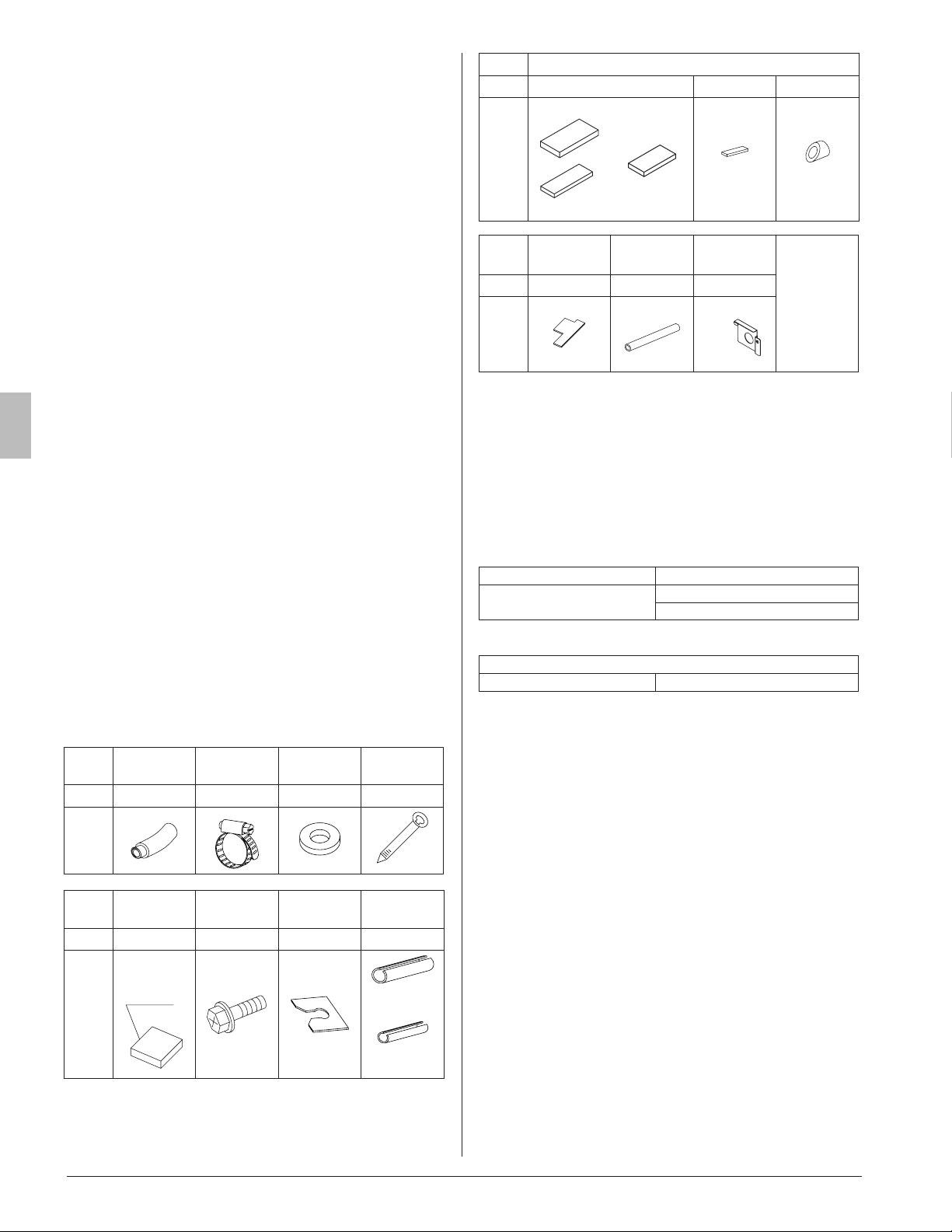
2-1 ACCESSORIES
Check if the following accessories are attached to the
indoor unit.
Name
(1) Drain
hose
(2) Metal
clamp
(3) Washer for
hanger
(4) Clamp
Quantity
1 pc. 1 pc. 8 pcs. 7 pcs.
Shape
Name
(5) Installation
pattern paper
(6) Screw
(M4)
(7) Washer
xing plate
Joint insulating
material
Quantity
1 sheet 4 pcs. 4 pcs. 1 each
Shape
Used as
packing
material
(8) For gas
piping
(9) For liquid
piping
Name Sealing material
Quantity
1 each 1 sheet 1 pc.
Shape
(10) Large
(11)
Medium-1
(12)
Medium-2
(13) Small
(14)
Name
(15) Installation
guide
(16) Insulation
tube
Conduit mounting
plate
(Miscellaneous)
•
Operation
Manual
•
Installation
Manual
•
Warranty
Card
Quantity
1 sheet 1 pc. 1 pc.
Shape
(17)
• Screws for xing the panel are attached to the decoration
panel.
2-2 OPTIONAL ACCESSORIES
• This indoor unit separately requires a decoration panel and
a remote controller.
• Conrm if a decoration panel shown in the Table 1 is pre-
pared and meets your model.
(Refer to the installation manual attached to the decoration
panel for how to install.)
Table 1
Unit model Optional decoration panel
FCQ 18 · 24 · 30 · 36 ·
42 · 48TAVJU
BYCQ125BGW1, BYCQ125B-W1
Color : Fresh white
Table 2
Remote Controller Model
Wired type BRC1E73
• Install the remote controller to the place where the cus-
tomer has given consent.
Refer to the catalog for the applicable model.
(Refer to the installation manual attached to the remote
controller for how to install.)
01_EN_3P161684-9U.indd 1 8/8/2018 15:26:48
2
English
CARRY OUT THE WORK GIVING CAUTION
TO THE FOLLOWING ITEMS AND AFTER THE
WORK IS COMPLETED CHECK THESE AGAIN
.
(1) Items to be checked after completion of work
Items to be checked In case of defective
Are the indoor and outdoor units
rigidly xed?
Drop · vibration ·
noise
Are the installation works of the out-
door and indoor units completed?
Does not operate ·
burnout
Have you carried out a leakage test
with the test pressure specied in
the outdoor unit installation manual?
Does not cool / Does
not heat
Is the insulation of refrigerant piping
and drain piping completely carried
out?
Water leakage
Does the drain ow out smoothly? Water leakage
Is the power supply voltage identical
to that stated in the manufacturer’s
label on the air conditioner?
Does not operate ·
burnout
Are you sure that there is no wrong
wiring or piping or no loose wiring?
Does not operate ·
burnout
Is grounding completed?
Danger in case of
leakage
Are the sizes of electric wiring ac-
cording to the specication?
Does not operate ·
burnout
Are any of air outlets or inlets of the
indoor and outdoor units blocked
with obstacles?
If so, it could cause the capacity
to drop due to fan-speed drop or
malfunction of equipment.
Does not cool /
Does not heat
Have you recorded the refrigerant
piping length and the refrigerant
charge added?
Refrigerant charge
amount is not clear
Make sure to recheck the items of
SAFETY CONSIDERATIONS
.
(2) Items to be checked at time of delivery
Items to be checked
Have you carried out eld setting? (if necessary)
Are the control box cover, the air lter, and the suction grille
attached?
Does the cool air discharge during the cooling operation and
the warm air discharge during the heating operation? Have
you checked to make sure the indoor unit does not make
unpleasant air-discharge sounds?
Have you explained how to operate the air conditioner while
showing the operation manual to the customer?
Have you explained to the customer the description of cool-
ing, heating, program dry and automatic (cooling/heating)
while showing the operation manual to the customer?
If you set the fan speed at thermostat OFF, did you explain
the set fan speed to the cus tomer?
Have you handed the operation manual and the installation
manual to the customer?
(3) Points of the operation explanation
In addition to the general usage, since the items in the
operation manual with the
WARNING and
CAUTION marks are likely to result in human
bodily injuries and property damages, it is neces sary
not only to explain these items to the customer but
also to have the customer read them.
3. SELECTION OF INSTALLATION LOCA-
TION
Holdthehangersat4locationstomovetheindoorunit
when unpacking or after unpacked, and do not apply force
to the piping (refrigerant and drain) and resin parts.
If the temperature and humidity in the ceiling is likely to
exceed86°F(30°C),RH80%,usetheoptionalkitforcop-
ing with high temperature and humidity, or additionally
stick the insulation to the indoor unit.
Use the insulation such as glass wool or polyethylene
thathasthicknessof3/8in.(10mm)ormore.However,
keep the insulated outside dimension smaller than the
ceiling opening so that the unit may go through the open-
ing at installation.
The direction of air discharge for this product can be
selected. Sealing material of air discharge outlet is
availableoptionfor4-waywithsealedcorners,and3-way.
(1) Select the installation location that meets the follow-
ing conditions and get approval of the cus tomer.
•
Where the cool and warm air spreads evenly in the room.
• Where there are no obstacles in the air passage.
• Where drainage can be ensured.
• Where the ceiling surface is not inclined.
• Where there is sufcient strength to withstand the
mass of the indoor unit. If the strength is insufcient,
the indoor unit may vibrate and get in contact with the
ceiling and generate noise.
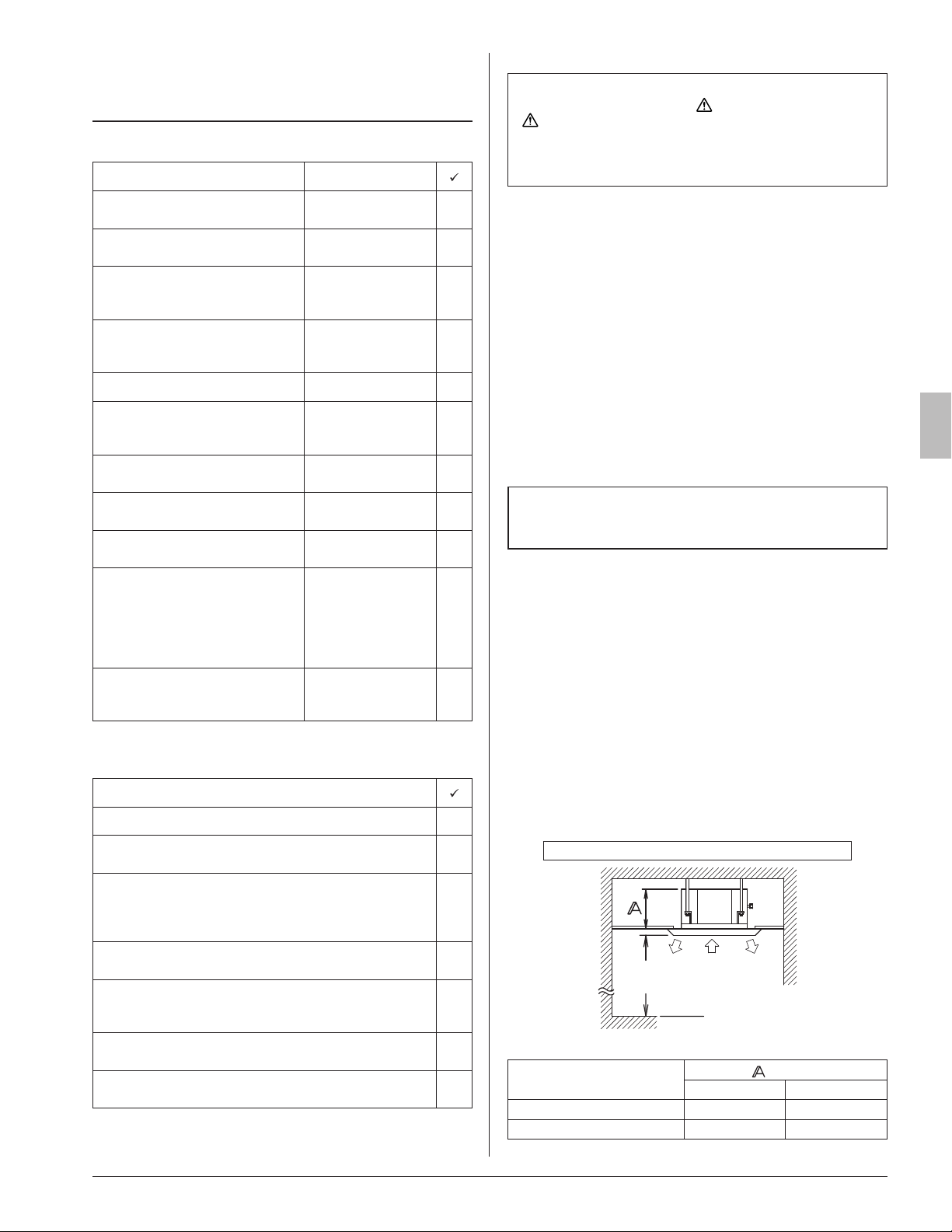
• Where a space sufcient for installation and service
can be ensured. (Refer to Fig. 1)
• Where the piping length between the indoor and the out-
door units is ensured within the allowable length. Refer
to the installation manual attached to the outdoor unit.
• Where there is no risk of ammable gas leak.
Required installation space [in. (mm)]
Suction Discharge
Discharge
Floor level
At least
70 (1800)
from a floor
Fig. 1
MODEL NAME
[in. (mm)]
BYCQ125B-W1
BYCQ125BGW1
18 · 24 10 (256) 13-1/4 (336)
30 · 36 · 42 · 48 11-3/4 (298) 14-7/8 (378)
01_EN_3P161684-9U.indd 2 8/8/2018 15:26:48
3
English
Indoor unit
Indoor unit
*60 (1,500)
or more
from a wall
(NOTE 2)
(NOTE 1)
Lighting
Exhaust
fan
At least 60 (1,500)
from any fixture
60 (1,500)
or more
80 (2,000) or more
160 (4,000) or more
Obstacles
[unit: in. (mm)]
Fig. 2
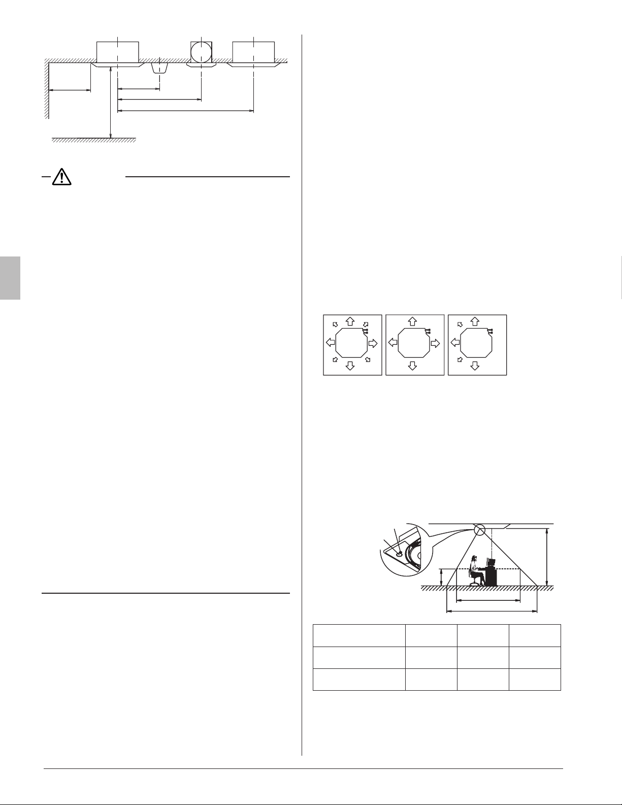
CAUTION
• Any vents, light xtures, or other appliances which may
disturb the airow might stain the ceiling if too close, so
follow Fig. 2 when installing.
Note)
1. This restriction applies to the exposed type lighting,
but does not apply to the recessed type, which does
not protrude below the ceiling line.
2. The clearance from the wall (indicated with *) must
be 20 in. (500 mm) or more if the air outlet is closed or
the horizontal blade is set to Airow block and, if the
corners (left and right corners of the target air outlet)
are also closed by 8 in. (200 mm) or more.
For how to set the airow direction (including Airow
block) with the horizontal blade, refer to Individual
AirowDirection in the operation manual attached
to the remote controller.
• Install the indoor and outdoor units, power supply wiring,
remote controller wiring and transmission wiring at least
3.3 ft. (1 m) away from televisions or radios to prevent im-
age interference or noise.
(Depending on the radio waves, a distance of 3.3 ft. (1 m)
may not be sufcient to eliminate the noise.)
• Install the indoor unit as far as possible from uorescent
lamps.
• Localized temperature difference from the room tempera-
ture, if too large, can affect how the infrared oor sensor
judges.
(This may occur, for example, in an area where oor
heating/high-temperature heat generating equipment is
installed.)
• Each sensor has been set so that the center of the sensing
area is located in the center of the product 32 in. (800 mm)
above the oor (in case of the infrared presence sensor)
or 0 in. (0 mm) above the oor (in case of the infrared oor
sensor) when the ceiling height is approximately 8-3/4 ft.
(2.7 m).
(2) Ceiling height
• This indoor unit can be installed in a space of which
ceiling height is up to 11-1/2 ft. (3.5 m) (Type 30 · 36 ·
42 · 48: 13-3/4 ft. (4.2 m))
•
However, if the ceiling height exceeds 8-3/4 ft. (2.7 m)
(Type 30 · 36 · 42 · 48: 10-1/2 ft. (3.2 m)), it is necessary
to set from the remote controller on site. Refer to the
section 10.FIELDSETTING.
(3) Direction of the air discharge
• Select the number of directions of the optimum air
discharge for the shape or the position of the room.
• The number of directions of the air discharge can be
changed by installing a sealing material.
• When installing a sealing material, the eld setting
from the remote controller is required. For details, refer
to the operation manual attached to the sealing materi-
als.
(It is set to the setting position number 01 (Standard ·
All round outlet) when shipped from the factory.)
• To use the optional sealing material kit to change the
setting of air discharge direction (4-way blow type (with
corners sealed)/3-way blow type), refer to the installa-
tion manual attached to it.
*: Refr
igerant
piping
***
[Direction of air discharge]
All round 4-way 3-way
Fig. 3
(4) Use suspension bolt for installation.
Investigate if the installation place can withstand the
mass of the indoor unit and, if necessary, hang the indoor
unit with bolts after it is reinforced by beams etc.
(Refer to the installation pattern paper (5) for the mount-
ing pitch.)
(5) Infraredpresence/oorsensor’ssensingarea
The sensing area is as shown in the gure below.
32 in. (800 mm)
h
φa
φb
[Target of detected area]
Infrared floor
sensor
Infrared
presence sensor
Indoor unit installation
height h [ft. (m)]
8-3/4 (2.7) 11-1/2 (3 .5) 13 (4.0)
Infrared presence sen-
sor fa [ft.
(m)
]
Approx.
28 (8.5)
Approx.
37-1/2 (11.5)
Approx.
44-1/2 (13.5)
Infrared oor sensor fb
[ft.
(m)
]
Approx.
36 (11)
Approx.
46 (14)
Approx.
52-1/2 (16)
01_EN_3P161684-9U.indd 3 8/8/2018 15:26:49
4
English
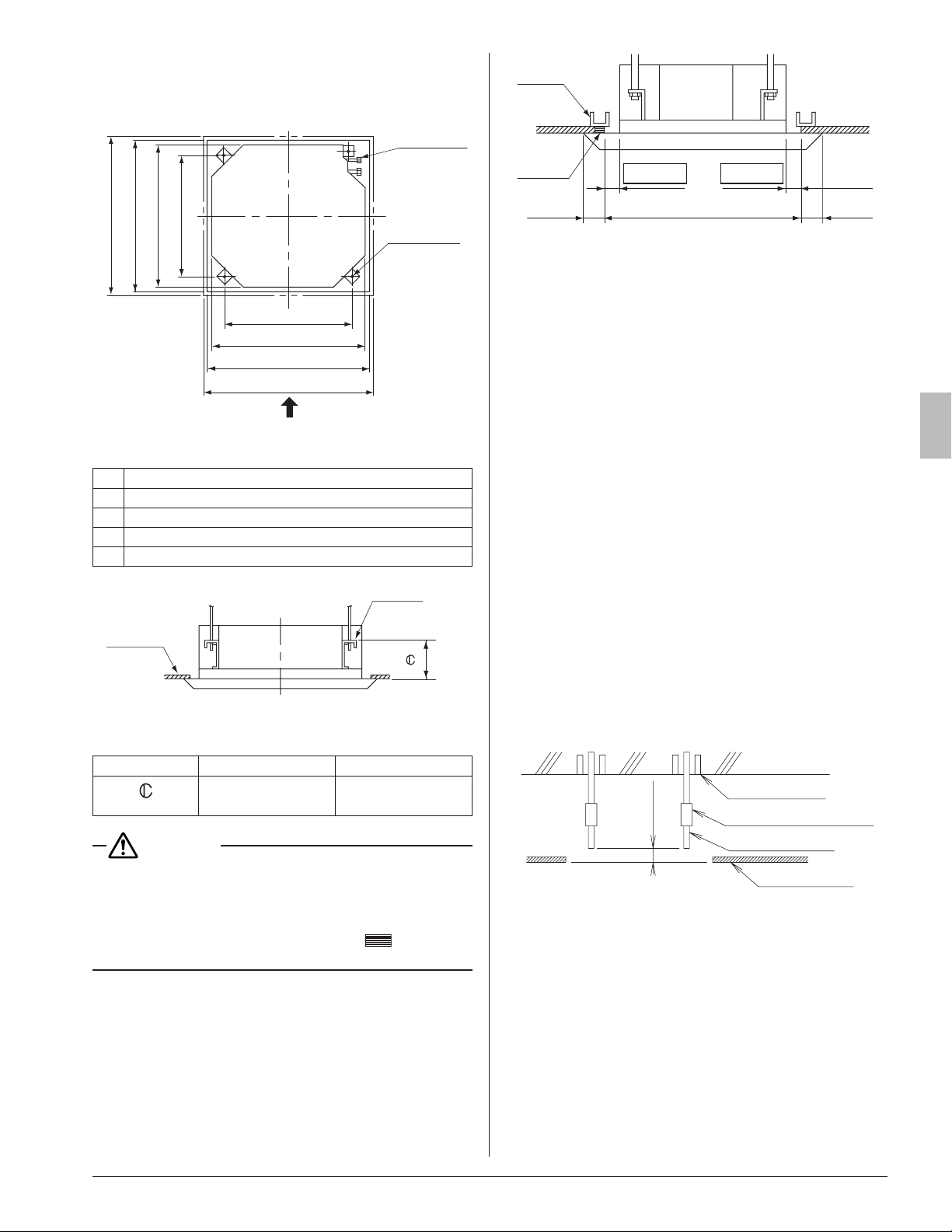
4. PREPARATION BEFORE INSTALLATION
(1) Check the relation of location between the ceiling
opening and the indoor unit suspension bolts.
1 Decoration panel
4 Suspension bolt pitch
3 Indoor unit
2 Ceiling opening
1 Decoration panel
2 Ceiling opening
3 Indoor unit
5 Suspension bolt pitch
Refrigerant
piping
Suspension
bolt (×4)
A
Fig.4
[unit: in. (mm)]
1 37-3/8 (950)
2 33-7/8 – 35-7/8 (860 – 910)
3 33-1/16 (840)
4 30-3/4 (780)
5 28 (710)
Ceiling
View as seen from A
Hanger
Fig. 5
Decoration Panel
BYCQ125B-W1 BYCQ125BGW1
in. (mm)
4-15/16 – 5-1/8
(125 – 130)
8-1/16 – 8-1/4
(205 – 210)
CAUTION
Reduce the distance between the unit and ceiling to
1-3/8 in. (35 mm) or below in order to maintain an over-
lapping panel margin 13/16in. (20 mm) for the opening
on the ceiling. If the distance exceeds 1-3/8in. (35mm),
attach ceiling material to the part marked
or replace
the ceiling. (RefertoFig.6)
Frame
≤1-3/8 (35) ≤1-3/8 (35)
33-7/8 to 35-7/8 (860 – 910)
(Ceiling-panel
overlapping
dimension)
Ceiling
material
(Ceiling-opening dimension)
≥13/16
(20)
≥13/16
(20)
[unit: in. (mm)]
Fig.6
(2) Make the ceiling opening required for installation.
• Use the installation pattern paper (5) matched to the
ceiling opening dimension.
• Make the ceiling opening required for installation at
the installation location and carry out refrigerant/drain
piping, power supply wiring, remote controller wiring
(not needed in case of wireless remote con troller) and
wiring between the indoor and outdoor units. (Refer
to each section 6.REFRIGERANTPIPINGWORK,
7.DRAINPIPINGWORK and 8.ELECTRICWIRING
WORK)
• After making the opening, sometimes it is necessary
to reinforce the ceiling framework to maintain a level
ceiling and prevent it from vibrating.
For details, consult with the builder and interior de-
signer.
(3) Install the suspension bolts.
• User either a M8-M10 size bolt or equipment.
• Use hole-in-anchors for the existing bolts and embed-
ded inserts or foundation bolts for new bolts, and x the
indoor unit rmly to the building so that it may withstand
the mass of the unit.
In addition, adjust clearance (2 – 4 in. (50 – 100 mm))
from the ceiling in advance.
<Installation examples>
2 – 4 in.
(50 – 100 mm)
Foundation bolt
Suspension bolt
Ceiling slab
Long nut or turn-buckle
Ceiling surface
Note) The above shown parts are all field supply.
5. INSTALLATION OF INDOOR UNIT
<<It is easy to attach the optional parts (except for deco-
ration panel) before installing the indoor unit. Refer to
also the installation manual attached to the optional
parts.>>
For installation, use the attached installation parts and
speciedparts.
[Install the indoor unit in the order of steps (1), (2), (3), (4), (5),
and (6) in case of a newly built ceiling, or in the order of steps
(1), (3), (4), and (5) in case of an existing ceiling.]
01_EN_3P161684-9U.indd 4 8/8/2018 15:26:50
5
English
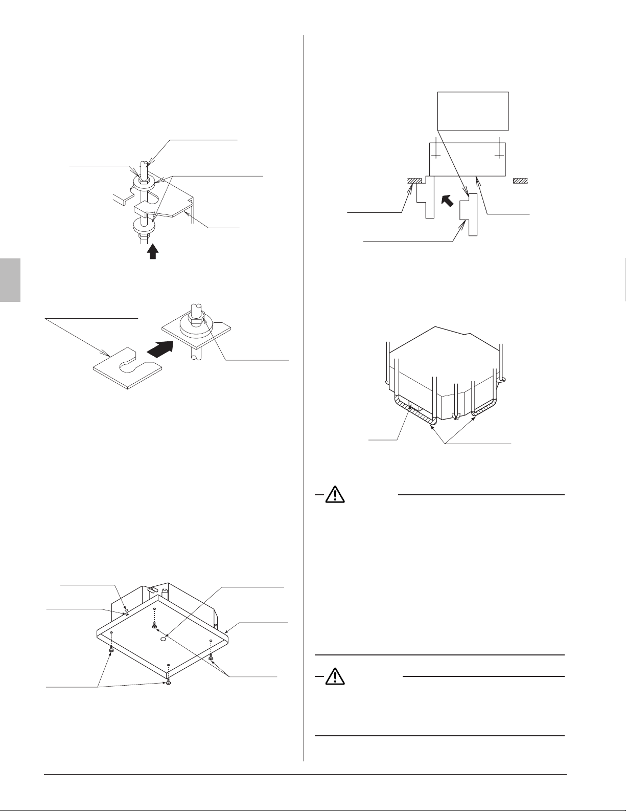
(1) Install the indoor unit temporarily.
• Connect the hangers to the suspension bolts. Be sure
to use and tighten the nut and washer (3) for each
hanger from both upper and lower sides of the hanger.
(RefertoFig.7)
If the washer xing plate (7), the upper side washer for
hanger (3) will be protected from falling off.
(RefertoFig.8)
[To fix hanger] Suspension bolt
Washer for hanger (3)
(accessory)
Hanger
Tighten the nut
(double nut)
Nut
(Field supply)
Fig.7
[Washer fixing plate (7) fixing method]
Washer fixing plate (7)
(accessory)
Upper side nut
Insert
Fig.8
(2)
• The installation pattern paper (5) is matched to the ceil-
ing opening dimension.
Conrm with builder the height of the ceiling from the
oor.
• The center of the ceiling opening is shown in the instal-
lation pattern paper (5).
The center of the indoor unit is indicated as triangle
marks on the sides and bottom of the unit and those on
the installation pattern paper (5).
• Align the triangle marks on the indoor unit with the
installation paper. Put the installation pattern paper (5)
on the indoor unit and x with four screws (6).
Installation
pattern
paper (5)
(accessory)
[Installation of the installation pattern paper]
Center of
ceiling opening
Screw (6)
(accessory)
Screw (6)
(accessory)
Center of the
indoor unit
Center mark
of the unit
<Installationworkaftertheceilingworkisnished>
(3)
Adjust so that the unit will be properly positioned.
(Refer to 4.PREPARATIONBEFOREINSTALLATION–(1))
• Using the Installation guide (15) allows you to check
the positions from the underside of the unit to the lower
ceiling surface.
Apply the short
side of the
cut-out section.
Lower ceiling
surface
Installation guide (15)
Underside
of the unit
(4) Check the level of the unit. (Refer to Fig. 9)
(5) Remove the washer xing plate (7) used for preventing
the washer for hanger (3) from falling and tighten the up-
per side nut.
(6) Remove the installation pattern paper (5).
Level
Vinyl tube
[Maintaining horizontality]
Fig. 9
CAUTION
• Install the indoor unit so it is horizontally level.
If the indoor unit is inclined and the drain piping side is
higher high, it may cause malfunction of a oat switch and
results in water leakage.
• Attach nuts on the upper and lower side of hanger.
If there is no upper nut and the lower nut is over-tightened,
the hanger and the top plate malfunction and create un-
wanted noise.
• Donotinsertmaterialsotherthanthosespecied
into the clearance between the hanger and the
washer for hanger (3).
Unless the washers are properly attached, the suspen-
sion bolt may come off from the hanger.
WARNING
The indoor unit must be securely installed on a
place that can withstand the mass.
If the strength is insufcient, the indoor unit may fall
down and cause injuries.
01_EN_3P161684-9U.indd 5 8/8/2018 15:26:51
6
English
6. REFRIGERANT PIPING WORK
• For the outdoor unit refrigerant piping, refer to the installa-
tion manual attached to the outdoor unit.
• Carry out insulation of both gas and liquid refrigerant piping
securely. If not insulated, it may cause water leakage. For
gas piping, use insulation material of which heat resistant
temperature is not less than 250°F (120 °C).
For use under high humidity, strengthen the insulation ma-
terial for refrigerant piping. If not strengthened, the surface
of insulation material may sweat.
• Before installation work, make sure that the refrigerant is
R410A or operation will malfunction.
CAUTION
This air conditioner is a dedicated model for new re-
frigerantR410A.Makesuretomeettherequirements
shown below and carry out installation work.
• Usededicatedpipingcuttersandaringtoolsfor
R410A.
• Whenmakingaareconnection,coatthearedin-
ner surface only with ether oil or ester oil.
• Useonlythearenutsattachedtotheaircondition-
er.Ifotherarenutsareused,itmaycauserefriger-
ant leakage.
• To prevent contamination or moisture from getting
into the piping, take measures such as pinch ing or
taping the pipings.
Donotmixsubstanceotherthanthespeciedrefrig-
erant such as air into the refrigeration circuit.
If the refrigerant leaks during the work, ventilate the
room.
• The refrigerant is pre-charged in the outdoor unit.
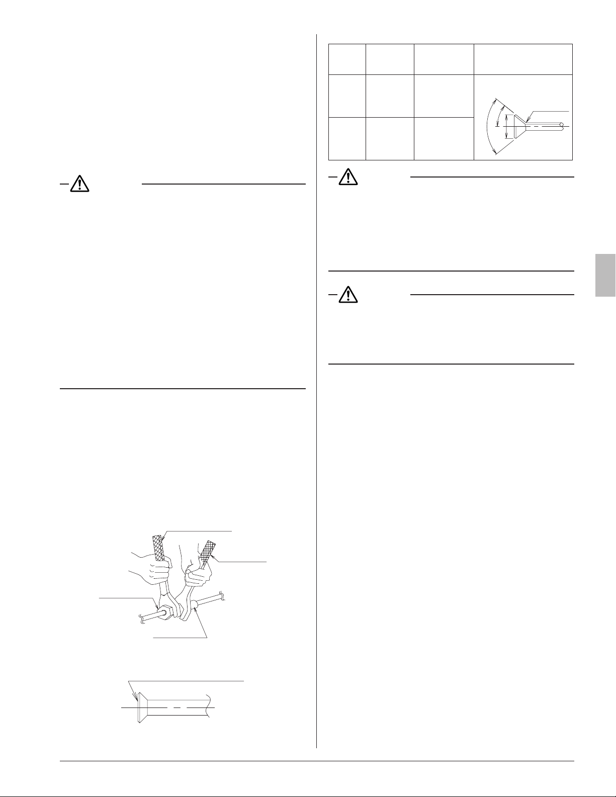
• When connecting the pipings to the air conditioner,
make sure to use a spanner and a torque wrench as
shown in Fig.10.
• For the dimension of ared part and the tightening
torque, refer to the Table 3.
• When making a are connection, coat the ared inner
surface only with ether oil or ester oil.
(Refer to Fig. 11)
Then, turn the are nut 3 to 4 times with your hand and
screw in the nut.
Torque wrench
Spanner
Flare nut
Union joint
Fig.10
Coat the flared inner surface
only with ether oil or ester oil
Fig. 11
Table 3
Piping
size
[in. (mm)]
Tightening
torque
[lbf·ft. (N·m)]
Dimension for
processing are
A [in. (mm)]
Flare shape
[in. (mm)]
f 3/8
(9.5)
24.1 – 29.4
(36.3±3.6)
0.504 – 0.520
(13.0±0.2)
R0.016-0.031
(0.4-0.8)
90°±2°
A
45°±2°
f 5/8
(15.9)
45.6 – 55.6
(68.6±6.8)
0.760 – 0.776
(19.5±0.2)
CAUTION
• Donotexcessivelytightenthearenut.
Doing so will break the are nut and refrigerant leakage
may occur.
• Makesurethatallpartsaroundthearearefreeof
oil.
The drain pan and the resin part may be deteriorated if
oil is attached.
CAUTION
Insulationofeldpipingmustbecarriedoutuptothe
connection inside the casing.
If the piping is exposed to the atmosphere, it may cause
sweating, burn due to touching the piping, electric shocks
or a re due to the wiring touching the piping.
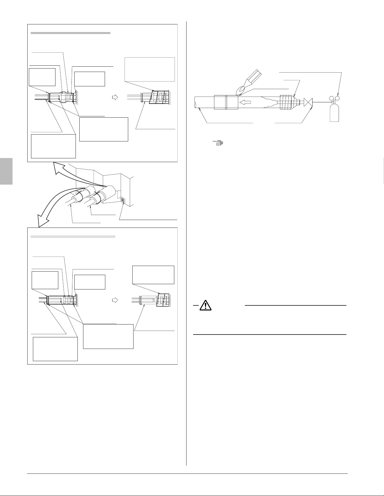
• After leak test, referring to Fig. 12, insulate both the
gas and liquid piping connection with the attached joint
insulating material (8) and (9) to prevent the pipings from
getting exposed.
Then, tighten the both ends of insulating material with
the clamp (4).
• Wrap the sealing material (Medium-1, 2) (11) (12) around
the joint insulating material (8) and (9) (are nut section),
both the gas and liquid piping.
• Make sure to bring the seam of joint insulating material
(8) and (9) to the top.
01_EN_3P161684-9U.indd 6 8/8/2018 15:26:51
7
English
Joint insulating
material (9)
(accessory)
Piping holding plate screw
(2 points)
Gas piping
Liquid piping
Liquid side piping insulating method
Indoor unit
Indoor unit
Clamp (4)
(accessory)
Sealing material
(11) Medium-1
(accessory)
Sealing material
(12) Medium-2
(accessory)
Clamp (4)
(accessory)
Piping
insulating
material
(field supply)
Gas side piping insulating method
Joint insulating
material (8)
(accessory)
Piping insulating
material (main unit)
Bring the
seam
to the top.
Flare nut
connection
Piping
insulating
material
(field supply)
Do not leave
clearance.
Flare nut
connection
Bring the
seam
to the top.
Do not leave
clearance.
Piping insulating
material (main unit)
Wind around the
piping until top of the
flare nut connection,
beginning at the base.
Wind around the
piping, beginning
at the base.
Do not expose the
piping in order to
prevent the vapor
condensation.
Tighten the portion
where overlapped by
the piping insulating
material.
Tighten the portion
where overlapped by
the piping insulating
material.
Do not expose the
piping in order to
prevent the vapor
condensation.
Fig. 12
• Before brazing refrigerant piping, have nitrogen ow
through the refrigerant piping and substitute air with
nitrogen (NOTE 1) (Refer to Fig. 13). Then, carry out
brazing (NOTE 2).
After all the brazing works are nished, carry out are
connection with the indoor unit. (Refer to Fig. 12)
Pressure reducing valve
Nitrogen
Taping
Stop valve
Brazing place
Nitrogen
Refrigerant piping
Fig. 13
NOTE
1. The proper pressure for having nitrogen ow through the
piping is approximately 2.9 psi (0.02 MPa), (close to the
pressure of breeze coming in contact with the cheek) with
a pressure-reducing valve.
2. Do not use ux when brazing refrigerant piping.
Use phosphor copper brazing ller metal (BCuP-2/B-
Cu93P-710/795) that does not require ux.
(If chlorinated ux is used, the piping will be corroded
and, in addition if uorine is contained, the refrig erant
oil will be deteriorated and the refrigerant circuit will be
affected badly.)
3. When carrying out leakage test of refrigerant piping
and the indoor unit after the installation of indoor unit is
nished, conrm the connecting outdoor unit installation
manual for test pressure.
Refer to the outdoor unit installation manual or technical
document for refrigerant piping.
4. In case of refrigerant shortage due to forgetting addi-
tional refrigerant charge etc., it will result in malfunctions
such as not cooling or heating.
Refer to the outdoor unit installation manual or technical
document for refrigerant piping.
CAUTION
Do not use antioxidant when brazing piping.
It may result in malfunction of components and clogging of
piping due to residue.
7. DRAIN PIPING WORK
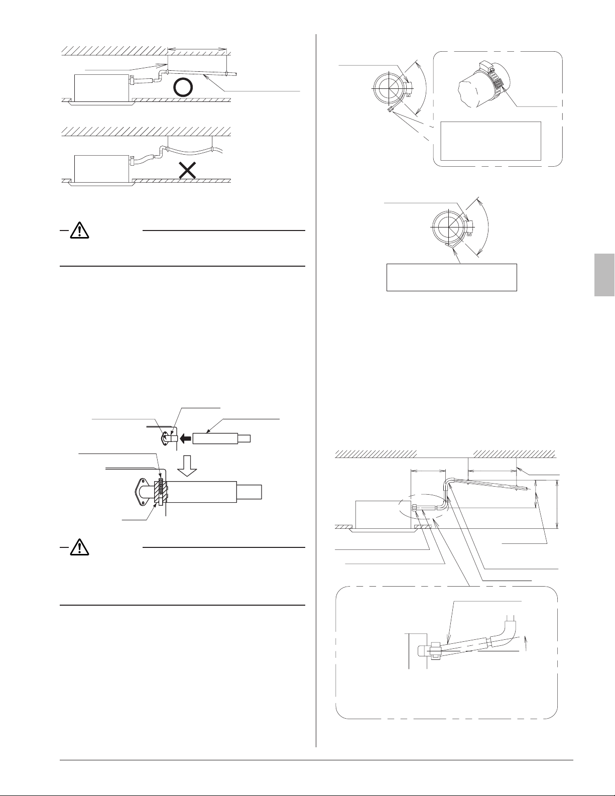
(1) Carry out drain piping.
Check that the piping ensures proper draining.
• Select the piping diameter equal to or larger than (ex-
cept for riser) that of the connection piping (PVC pipe
piping, nominal diameter 1 in. (25mm), outside diam-
eter 1-1/4 in. (32mm)).
• Install the drain piping as short as possible with
downward inclination of 1/100 or more where air can-
not stagnate. (RefertoFig.14) Bubbling sound may
occur.
01_EN_3P161684-9U.indd 7 8/8/2018 15:26:52
8
English
Downward
inclination of
1/100 or more
3–5 ft. (1–1.5 m)
Support
Good
Wrong
Fig.14
CAUTION
If drainage stagnates in the drain piping, the piping may get
clogged.
• If sufcient downward inclination cannot be ensured,
carry out upward drain piping.
• Install supports at a distance of 3–5 ft. (1–1.5 m) so that
the piping may not deect. (RefertoFig.14)
• Make sure to use the attached drain hose (1) and the
metal clamp (2).
Insert the drain hose (1) into the drain socket up to the
point where the socket diameter becomes larger.
Put the metal clamp (2) to the taped hose end and tight-
en the metal clamp (2) with torque 1.0 lbf·ft. (1.35±0.15
N·m).
Metal clamp (2)
(accessory)
Drain socket
Tape
Hose end
Drain hose (1)
(accessory)
Fig. 15
CAUTION
• Do not tighten the metal clamp (2) with the torque more
than the specied value.
The drain hose (1), the socket or the metal clamp (2) may
be damaged.
• Wrap the vinyl tape around the end of the metal clamp
(2) so that the sealing material (Large) (10) to be used
at the next process may not be damaged with the
clamp end or bend the tip of the metal clamp (2) inward
as shown. (RefertoFig.16)
<In case of sticking vinyl tape>
Tightened part
approx. 90°
Stick vinyl tape without
tearing the sealing
material (Large) (10) .
Vinyl tape
<In case of bending the tip>
Bend the tip without tearing the
sealing material (Large) (10).
Tightened part
approx. 90°
Fig.16
< Caution to be taken when carrying out upward
drainpiping(RefertoFig.17)>
•
The maximum height of the drain riser is 26-1/2 in.
(675mm) Since the drain pump mounted on this indoor
unit is a high head type, from the characteristic point of
view, the higher the drain riser the lower the draining noise.
Therefore, the drain riser of 11-3/4 in. (300 mm) or
higher is recommended.
• For upward drain piping, keep the horizontal piping dis-
tance of 11-3/4 in. (300 mm) or less between the drain
socket root to the drain riser.
Ceiling slab
≤ 11-3/4 (300)
3-5 ft. (1-1.5 m)
Support
[Unit: in. (mm)]
Metal clamp (2) (accessory)
Drain hose (1) (accessory)
Upward drain piping
Drain riser
Adjustable
(≤ 26-1/2 (675))
(≤ 33-1/2 (850))
Drain hose (1)
(accessory)
Level or upward
inclination
Keep the drain hose level or make a slight upward
inclination so that air may not stagnate in the drain hose.
If air stagnates, the drain may flow oppositely when the
drain pump stops and generate an abnormal sound.
Fig.17
01_EN_3P161684-9U.indd 8 8/8/2018 15:26:53
9
English
CAUTION
• Do not apply excessive force to the attached drain
hose (1) by bending or twisting it.
This could cause water leakage.
•
In case of centralized drain piping, carry out piping work
according to the procedure shown in the fol lowing
Fig.18.
Make a downward inclination of 1/100
or more to avoid stagnancy of air.
If water stagnates in the drain
piping, it may cause clogging of
drain piping.
0 to 26-1/2 in.
(0 – 675 mm)
Centralized drain piping
Fig.18
• Select a size for the centralized drain piping that meets
the capacity of indoor units to be con nected. Refer to
the technical document.
• When installing the new indoor unit, use the attached
new drain hose (1) and the metal clamp (2).
If an old drain hose or a metal clamp is used, it may
cause water leakage.
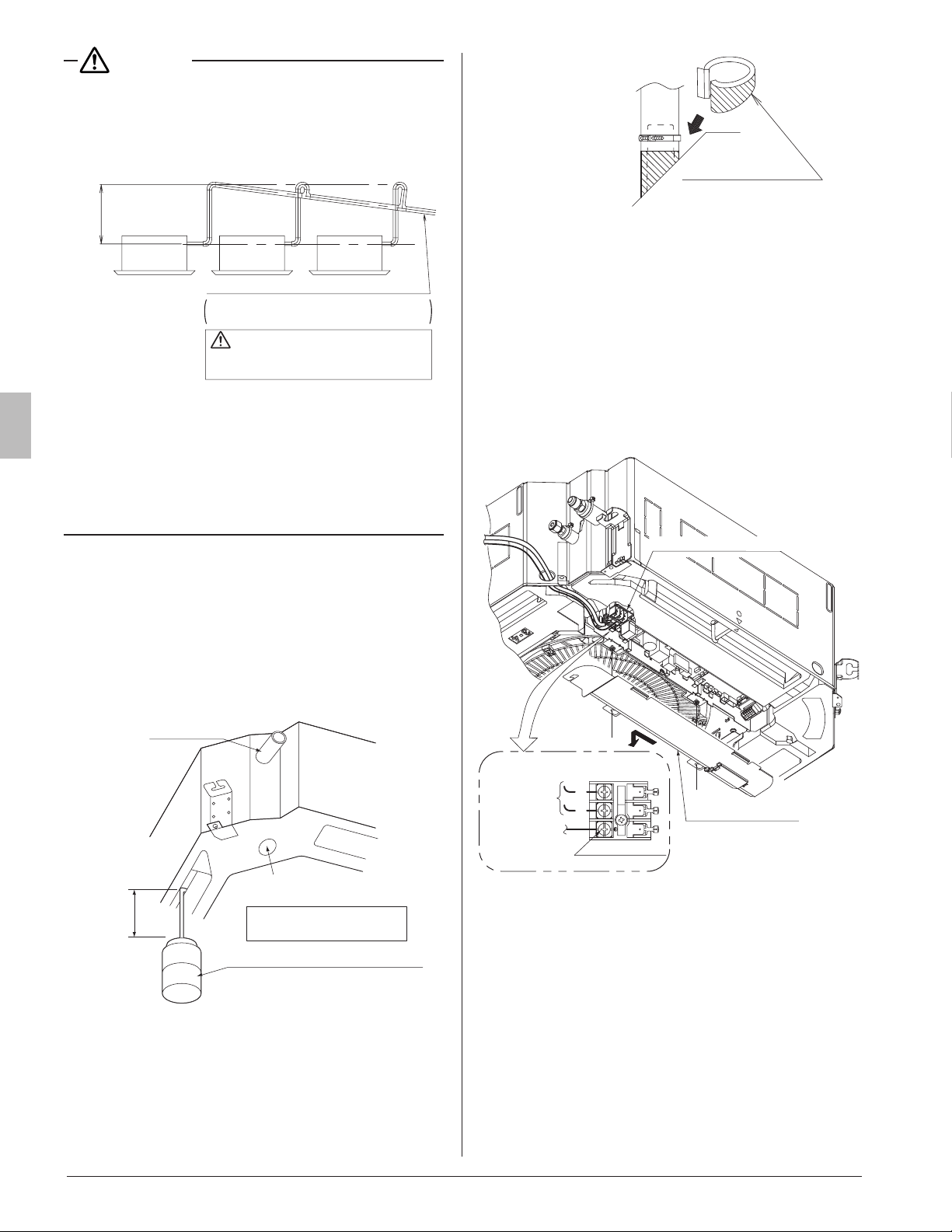
(2) Afterpipingisnished,checkifthedrainows
smoothly.
[Whentheelectricwiringworkisnished]
• Gradually pour 1/4 gal. (1 ℓ) of water from the air outlet
on the left side of the drain socket into the drain pan
using caution to avoid splashing water on the electric
components such as the drain pump. Conrm drainage
by operating the indoor unit under cooling mode ac-
cording to 10.FIELDSETTING. (Refer to Fig. 19)
≥4 in. (100 mm)
Plastic container for pouring water
(Tube length of 4 in. (100 mm) or
more is necessary. )
Drain outlet for service
(with rubber plug)
Drain piping
Use it when draining water
in the drain pan
[Method of adding water]
Fig. 19
• After checking the drainage of water, refer to Fig.20
and attach the sealing material (14) to perform the
thermal insulation of the drain socket.
Sealing material (14)
(accessory)
Fig.20
[Whentheelectricwiringworkisnotnished]
• The electric wiring works (including ground) must be
carried out by a qualied electrician.
• If a qualied person is not present, after the electric
wiring work is nished, check the drainage accord ing
to the method specied in [When the electric wiring
workisnished].
1. Open the control box cover and connect the single
phase 208/230 V power supply to the terminal (L
1
, L
2
)
on the terminal block (X2M).
Connect the ground wiring to the ground terminal.
(Refer to Fig. 21)
L
1
L
2
LN
Single phase
power supply
208/230 V
Control box cover
Ground terminal
Ground wire
Terminal block (X2M)
Fig. 21
2. Make sure the control box cover is closed before
turning on the power supply.
• Throughout the whole process, carry out the
work using caution with wiring around the control
box so that the connectors not come off.
3. Gradually pour 1/4 gal. (1 ℓ) of water from the air
outlet on the left side of the drain socket into the
drain pan using caution to avoid splashing water on
the electric components such as the drain pump.
(Refer to Fig. 19)
01_EN_3P161684-9U.indd 9 8/8/2018 15:26:55
10
English
4. When the power supply is turned on, the drain pump
should operate. Drainage can be checked at the
transparent part of the drain socket.
(The drain pump will automatically stop after 10
minutes.)
After checking the drainage of water, refer to Fig.20
and attach the sealing material (14) to perform the
thermal insulation of the drain socket.
• Do not connect the drain piping directly to the
sewage that gives off ammonia odor.
The ammonia in the sewage may go through the
drain piping and corrode the heat exchanger of
the indoor unit.
• Do not apply external force to the oat switch or it
could cause malfunction.
5. Turn off the power supply after checking drainage,
and remove the power supply wiring.
6. Attach the control box cover as before.
• Do not touch the electronic parts other than the
terminal block (X2M).
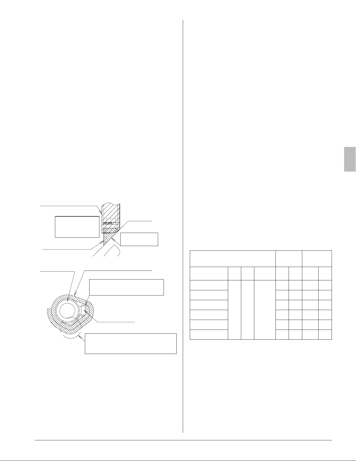
(3) Sweating may occur and result in water leakage.
Therefore, make sure to insulate the indoor drain pip-
ing and socket locations.
After drainage is checked, put the attached sealing
material (14) referring to Fig.20, and insulate the drain
hose (1) and the metal clamp (2) with the attached seal-
ing material (Large) (10) referring to Fig. 22.
Start wrapping from where the
metal clamp (2) is tightened.
Wrap the sealing material (Large) (10)
so that the metal clamp (2) end side
may be doubled.
Metal clamp (2)
(accessory)
Drain hose (1)
(accessory)
Sealing material (Large) (10)
(accessory)
Sealing material (14)
(accessory)
Sealing material - Large
(10) (accessory)
Be sure to lay the
sealing material
(10) on (14).
Do not have
the clearance.
Fig. 22
8. ELECTRIC WIRING WORK
8-1 GENERAL INSTRUCTIONS
• Make sure that all electric wiring work is carried out by
qualied personnel according to the applicable legislation
and this installation manual, using a separate dedicated
circuit.
Insufcient capacity of the power supply circuit or improper
electrical construction may lead to electric shocks or a re.
• Make sure to install a ground fault circuit interrupter.
Failure to do so may cause electrical shocks and a re.
• Do not turn on the power supply (branch switch, branch
overcurrent circuit breaker) until all the works are nished.
• Make sure to ground the air conditioner.
Grounding resistance should be according to applicable
legislation.
• Do not connect the ground wiring to gas or water pipings,
lightning conductor or telephone ground wiring.
• Gas piping .................Ignition or explosion may occur if
the gas leaks.
• Water piping ..............Hard vinyl tubes are not effective
ground.
• Lightning conductor or telephone ground wiring ..............
Electric potential may rise abnormally if struck by a light-
ning bolt.
• For electric wiring work, refer to also the WIRING DIA-
GRAM attached to the control box cover.
• Carry out wiring between the outdoor units, indoor units
and the remote controllers according to the wiring diagram.
• Carry out installation and wiring of the remote controller
according to the installation manual attached to the remote
controller.
• Do not touch the Printed Circuit Board assembly. It may
cause malfunction.
8-2 ELECTRICAL CHARACTERISTICS
Units
Power
supply
Fan motor
Model Hz Volts
Voltage
range
MCA MOP KW FLA
FCQ18TAVJU
60
208/
230
Max. 253
Min. 198
0.6 15 0.048 0.5
FCQ24TAVJU 0.7 15 0.048 0.5
FCQ30TAVJU 1.3 15 0.106 1.0
FCQ36TAVJU 1.5 15 0.106 1.2
FCQ42TAVJU 1.8 15 0.106 1.4
FCQ48TAVJU 1.8 15 0.106 1.4
MCA: Minimum Circuit Ampacity (A)
MOP:Maximum Overcurrent Protective Device (A)
KW: Fan Motor Rated Output (kW)
FLA: Full Load Ampere (A)
01_EN_3P161684-9U.indd 10 8/8/2018 15:26:55
11
English
8-3 SPECIFICATION FOR FIELD SUPPLY FUSES
AND WIRING
Model
Power supply wiring
Remote controller wiring
Transmission wiring
Fuse
Size Wire Size
FCQ18TAVJU
15A
Wiring size
and length
must
comply
with local
codes.
2-conductor,
stranded
non-shielded
copper cable
PVC/vinyl
jacket
(NOTE)
AWG18-16
(0.75-
1.25 mm
2
)
FCQ24TAVJU
FCQ30TAVJU
FCQ36TAVJU
FCQ42TAVJU
FCQ48TAVJU
Allowable lengths of transmission wiring and remote controller
wiring are as follows.
(1) Outdoor unit – Indoor unit
.................... Max. 3280 ft (1,000 m)
(2)
Indoor unit – Remote controller .............. Max. 1640 ft (500 m)
NOTE
• Vinyl cord with sheath or cable (Insulated thickness :
1/16 in. (1 mm) or more)
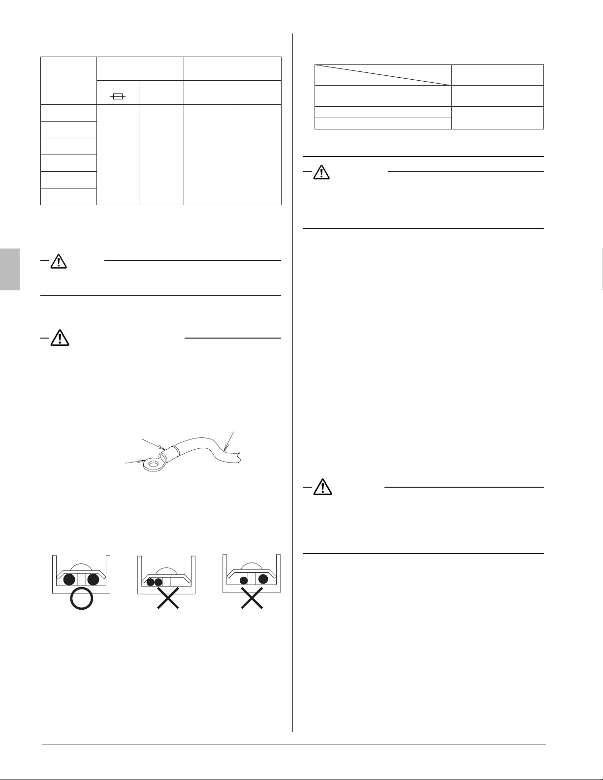
8-4 WIRING CONNECTION METHOD
CAUTION FOR WIRING
• The indoor units in the same system can be connected to
the power supply from one branch switch. How ever, selec-
tion of branch switch, branch over current circuit breaker
and wiring size must be according to applicable legislation.
• For connection to the terminal block, use a ring type crimp
style terminals with insulation sleeve or insulate the wirings
properly.
Insulation sleeve
Ring type crimp
style terminals
Wiring
• If the above is not available, make sure to fulll the following
requirements.
Connection of 2
wirings of same
size must be
carried out on
both sides.
Connection of
wirings of
different sizes is
prohibited.
Connection of 2
wirings on one
side is
prohibited.
(Abnormal heating may occur if the wirings are not tight-
ened securely.)
• Use the required wirings, connect them securely and x
these wirings securely so that external force may not apply
to the terminals.
• Use a proper screw driver for tightening the terminal
screws.
If an improper screw driver is used, it may damage the
screw head and a proper tightening cannot be car ried out.
• If a terminal is over tightened, it may be damaged.
Refer to the table shown below for tightening torque of
terminals.
Tightening torque
[lbf·ft. (N·m)]
Terminal block for remote controller
and transmission wirings
0.65 ± 0.06
(0.88 ± 0.08)
Terminal for power supply
0.96 ± 0.07
(1.3 ± 0.1)
Ground terminal
• Do not carry out soldering nish when stranded wirings
are used.
WARNING
• When wiring, form the wirings orderly so that the control
box cover can be securely fastened. If the control box cover
is not in place, the wirings may oat up or be sandwiched by
the box and the lid and cause electric shocks or a re.
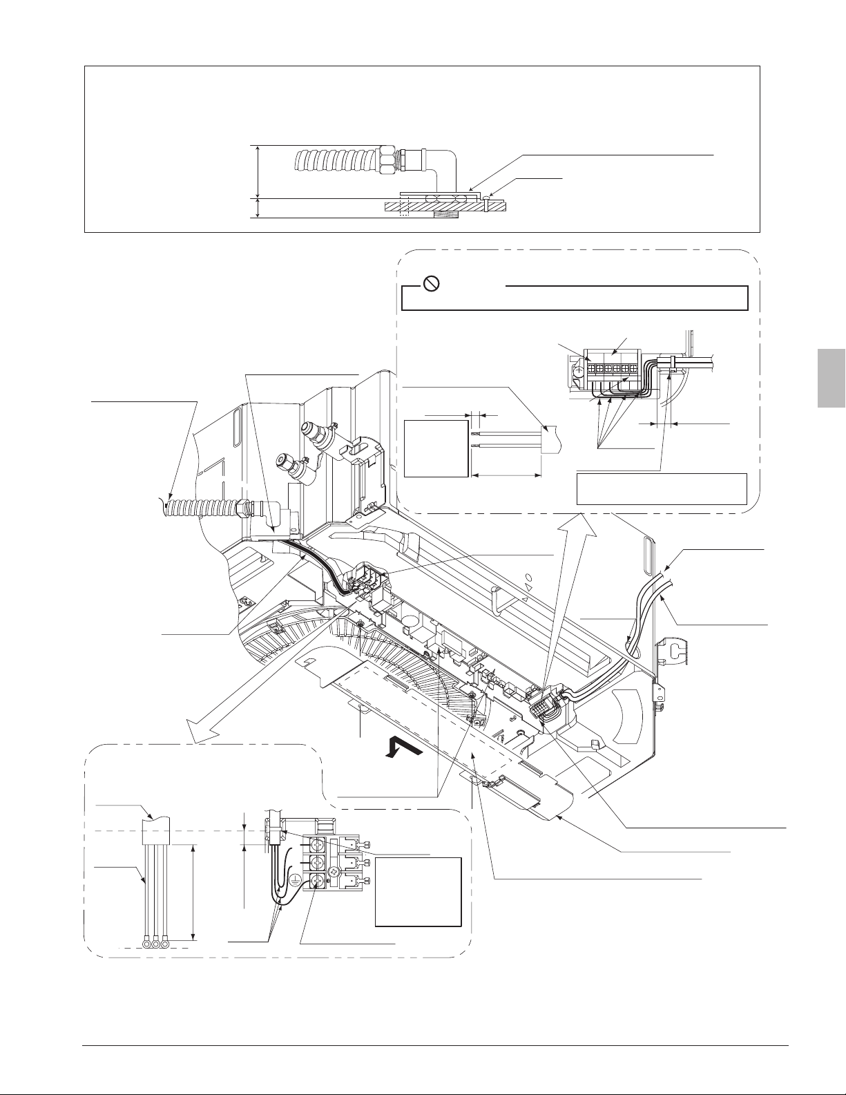
<Powersupplywiring·groundwiring·remotecontroller
wiring·transmissionwiringconnectingmethod>
• Power supply wiring, ground wiring
Pass the power supply wire through the attached insula-
tion tube (16) between the outlet of conduit and the power
supply terminal, and bind them together with the attached
clamp (4). (Refer to Fig. 23-2)
Use a pair of conduit mounting plates (17) to connect a
conduit to the unit as shown Fig. 23-1. After connecting the
power supply wiring to [L
¹
· L
²
] on the power supply terminal
block (X2M) and the ground wiring to the ground terminal,
clamp them near the terminal block using the attached
clamp (4). (Refer to Fig. 23-2)
Remote controller wiring, transmission wiring
Pull the wiring through the wiring penetrating hole (low volt-
age). After connecting the remote controller wir ing to [P
¹
·
P
²
] and the transmission wiring to [F
¹
· F
²
] on the terminal
block (X1M), clamp them near the terminal block using the
attached clamp (4). (Refer to Fig. 23-2)
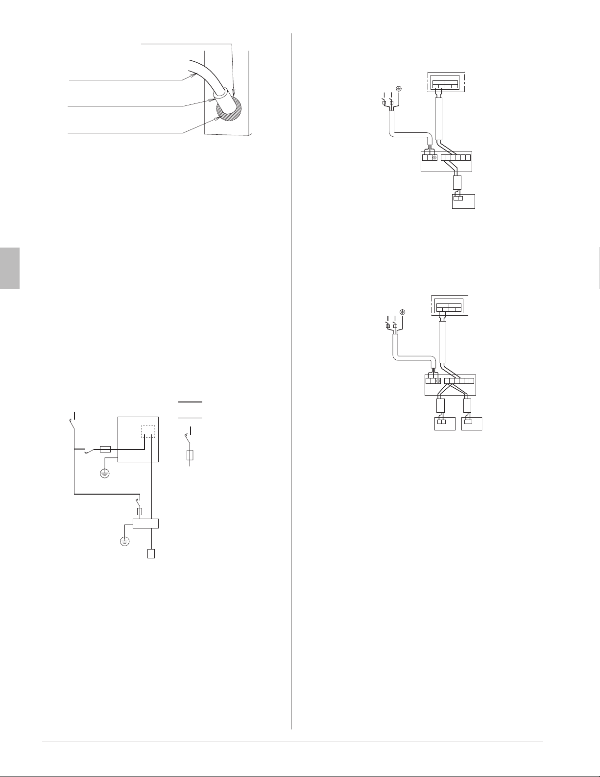
• After connecting the wiring, make sure to stick the sealing
material (Small) (13) to the wiring penetrating hole to pre-
vent water from entering the indoor unit. (RefertoFig.24)
CAUTION
•
Never connect the power supply wiring to the terminal
block for remote controller/transmission wiring (X1M).
If may damage the total system.
• Do not connect the remote controller/transmission wir-
ing to the wrong terminal block.
01_EN_3P161684-9U.indd 11 8/8/2018 15:26:56
English
3/8 to 5/8 in.
(10 – 15 mm)
3/8 to 5/8 in.
(10 – 15 mm)
2-3/4 to 3-1/2 in.
(70 – 90 mm)
2-3/4 to 3-1/2 in.
(70 – 90 mm)
Approx.
1/4 in. (7 mm)
L
1
L
2
LN
Remote
controller wiring
Transmission
wiring
Forced
off
P1 P2 F1 F2 T1 T2
Ground
wiring
Ground terminal
Control box cover
[Remote controller wiring, Tr ansmission wiring]
[
Power supply wiring, Ground wiring
]
Sheathed part of
remote controller wiring,
transmission wiring
• Do not connect the power supply wiring (high voltage).
R10
or more
R10
or more
Strand the
wirings after
sheath is
peeled off.
After the wirings are clamped,
cut off the extra part.
After the
wirings are
clamped, cut
off the extra
part.
(Sheath peeling
off allowance.)
(Sheath peeling
off allowance.)
Clamp (4)
Clamp (4)
Wiring
penetrating
hole (low
voltage)
Te rminal block for
power supply wiring/
grounding wiring (3P)
Te rminal block for
remote controller wiring/
transmission wiring (X1M)
Wiring diagram label
(on backside of control box cover)
Printed Circuit
Board
Sheathed
part
Prohibited
Transmission
wiring
Remote
controller wiring
• Use a 90° elbow type of conduit with dimensions Fig. 23-1 to prevent it from hitting the swing motor hous-
ing of decoration panel.
• Do not dispose the screw which assembles casing and resin together. The screw will be used to install
conduit mounting plate. Make sure to install the conduit mounting plate first before wiring.
Fig. 23-1
Power supply and
ground wire
Conduit mounting
plate (17)
Insulation
tube (16)
Conduit mounting plate (17)
<1-3/8 (35)
≥
3/8 (10)
Screw
Fig. 23-2
12
01_EN_3P161684-9U.indd 12 8/8/2018 15:26:57
13
English
Wiring penetrating hole
Remote controller
wiring/transmission wiring
Sealing material
(Small) (13)
(accessory)
Putty or insulation
(field supply)
Fig.24
<<Mending method of wiring penetrating hole>>
• After wiring connection is nished, to prevent the penetra-
tion of water, small animals and insects into the indoor unit
from the outside, mend the respective covers for wiring
penetrating hole for the power supply wiring/ground wiring
and the remote controller wiring/transmission wiring.
• Cut the sealing material (Small) (13) into two pieces and
wrap each wiring with each piece.
• Seal the clearance around the wirings with putty and insu-
lating material (eld supply).
If insects and small animals get into the indoor unit, short
circuiting may occur inside the control box.
• Keep the distance of 1-15/16 in. (50 mm) or more between
low voltage wiring (remote controller wiring, transmission
wiring) and the high voltage wiring (power supply wiring,
ground wiring) at anywhere outside the indoor unit. If both
wirings are laid down together, they may be affected by
outside electrical noise and cause malfunction or failure.
8-5 WIRING EXAMPLE
COMPLETE SYSTEM EXAMPLE
Power supply
Main
switch
Outdoor unit
Power supply wire
Transmission wire
Disconnect switch
Fuse/Breaker
Indoor unit
Remote controller
Fig. 25
1.When using 1 remote controller (Normal operation)
L1L2
IN/D OUT/D
F
1 F2 F1 F2
P
1
P
2
P
1
P
2
F
1
F
2
T
1
T
2
Control box
Power Supply
208/230V
1~ 60Hz
Outdoor unit
Indoor unit
Remote
controller
L
1
L
2
Fig.26
2. When using 2 remote controllers
P
1
P
2
P
1
P
2
L1L2
IN/D OUT/D
F
1 F2 F1 F2
P
1
P
2
F
1
F
2
T
1
T
2
Control box
For use with
2 remote
controllers
Power Supply
208/230V
1~ 60Hz
Outdoor unit
Indoor unit
L
1
L
2
Fig.27
[PRECAUTIONS]
1. Do not ground the equipment on gas pipes, water pipes
or lightning rods, or crossground with telephones.
Improper grounding could result in electric shock.
2. The remote controller wiring (P
¹
and P
²
) and transmis-
sion wiring (F
¹
and F
²
) have no polarity.
01_EN_3P161684-9U.indd 13 8/8/2018 15:26:58
14
English
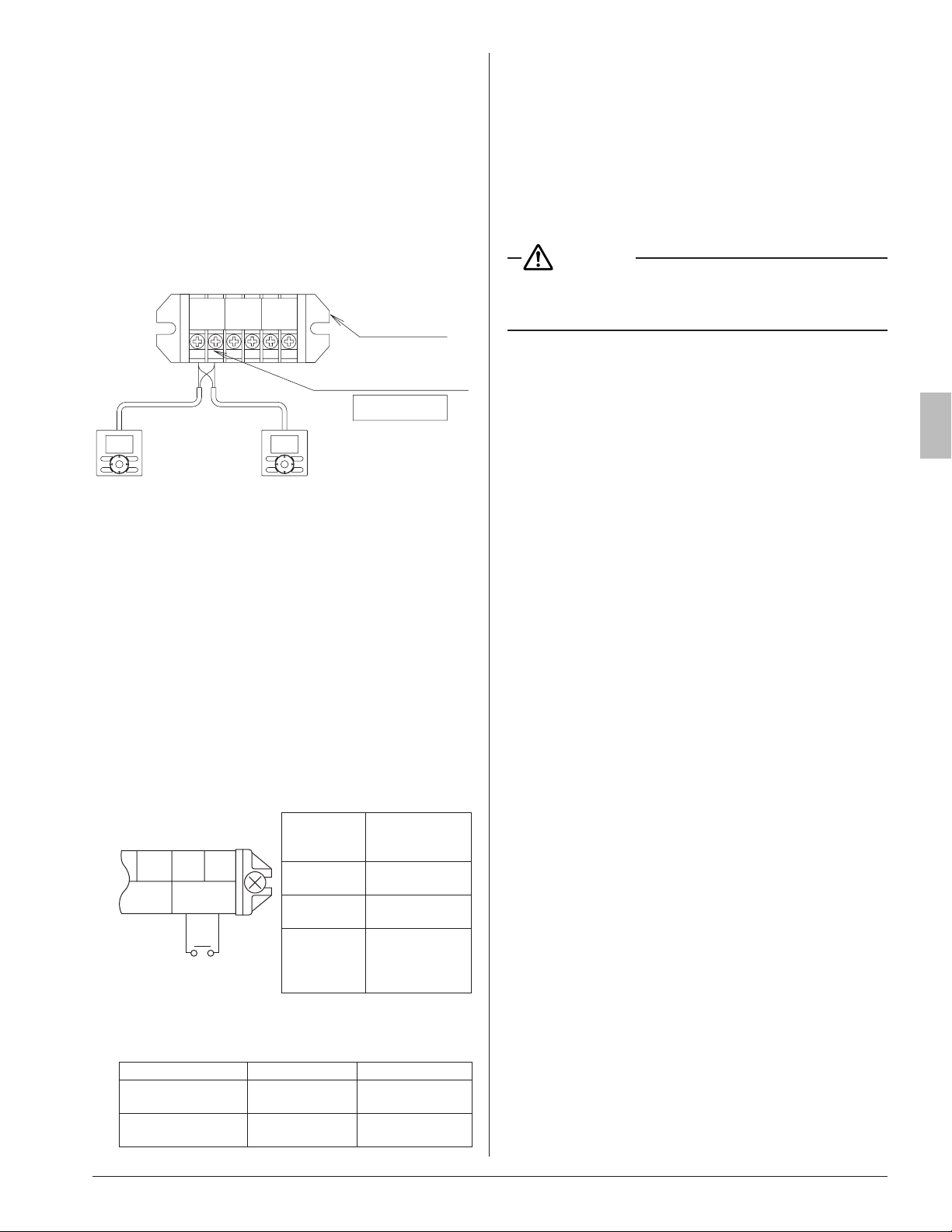
8-6 FOR CONTROL WITH 2 REMOTE CONTROL-
LERS (TO CONTROL 1 INDOOR UNIT WITH 2
REMOTE CONTROLLERS)
• For control with 2 remote controllers, set one remote con-
troller as Main and the other remote controller as Sub.
< Changeover method from Main to Sub and vice versa >
Refer to the installation manual attached to the remote
controller.
< Wiring method >
(1) Remove the control box cover.
(2) Carry out additional wiring from the remote controller
2 (Sub) to the terminals (P
¹
, P
²
) for remote controller
wiring on the terminal block (X1M) in the control box.
Te rminal for remote
controller wiring (P
1
, P
2
)
No polarity
Remote
controller 2
(Sub)
Remote
controller 1
(Main)
Te rminal block
(X1M)
F2F1P2P1 T2T1
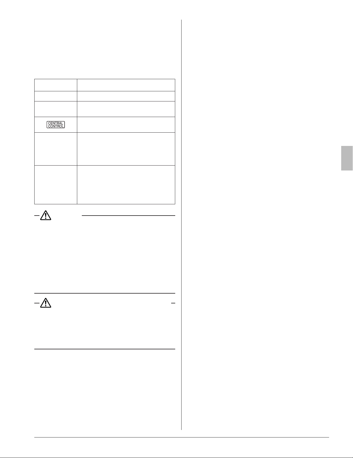
8-7 FOR CENTRALIZED CONTROL
• When centralized equipment (such as centralized control-
ler) is used for control, it is required to set the group No. on
the remote controller.
For details, refer to the manuals attached to the centralized
equipment.
• Connect the centralized equipment to the indoor unit con-
nected to the remote controller.
8-8 FOR REMOTE CONTROL (FORCE OFF OR ON /
OFF OPERATION)
(1) Wiringmethodandspecication
• Remote control is available by connecting the external
input to the terminal T
¹
and T
²
on the terminal block for
remote controller and transmission wiring (X1M).
F2 T1 T2
FORCED
OFF
Input A
Wiring
specication
Sheathed vinyl
cord or 2 core
cable
Gauge
AWG18-16
(0.75 – 1.25 mm
2
)
Wiring length
Max. 328 ft.
(100 m)
External
contact spec
Contact that can
make and break
the min. load of
15 V DC , 1 mA
(2) Actuation
• Input A of FORCED OFF and ON/OFF OPERATION
will be as the table shown below.
Input A = ON Input A = OFF
In case of FORCED
OFF
Remote controller
prohibited
Remote controller
permitted
In case of ON/OFF
OPERATION
Operation Stop
(3) How to choose FORCED OFF or ON/OFF OPERA-
TION
• For choosing FORCED OFF or ON/OFF OPERATION,
setting by remote controller is required.
(Refer to 10.FIELDSETTING.)
9. MOUNTING DECORATION PANEL
<<If test operation is required before mounting the deco-
rationpanel,10.FIELDSETTINGcanbecarriedoutbefore
9. MOUNTING DECORATION PANEL.>>
CAUTION
In case of a wireless remote controller, unless the decoration
panel is mounted, eld setting and test opera tion cannot be
carried out.
Refer to the installation manual attached to the decoration
panel.
• After the decoration panel is mounted, check if no clear-
ance exists between the panel and the unit.
• If test operation is carried out before mounting the decora-
tion panel, check the swing blade action after the panel is
mounted.
01_EN_3P161684-9U.indd 14 8/8/2018 15:26:58
15
English
10. FIELD SETTING
<<Refer to also the installation manual attached to the
outdoor unit.>>
CAUTION
Before carrying out eld setting, check the items mentioned in
Clause 2: (1) Items to be checked after completion of work
on page2. Check if all the installation and piping works for
the air conditioner are completed.
• Check if the control box covers of the air conditioner are
closed.
< FIELD SETTING >
<<Afterturnonthepowersupply,carryouteldsetting
from the remote controller according to the installation
state.>>
• Carry out setting at 3 places, MODE NO., FIRST CODE
NO. and SECOND CODE NO.
The settings shown by
in the table indicate those
when shipped from the factory.
• The method of setting procedure and operation is shown in
the installation manual attached to the remote controller.
• In case of remote control, for changeover of input to
FORCED OFF or to ON/OFF OPERATION.
[1] Enter into the field setting mode with the remote controller.
[2] Select MODE NO. 22.
[3] Set the FIRST CODE NO. to 1.
[4-1] For FORCE OFF, set the SECOND CODE NO. to 01.
[4-2] For ON/OFF OPERATION, set the SECOND CODE
NO. to 02.
(It is set to FORCE OFF when shipped from the factory.)
• Ask your customer to keep the manual attached to the
remote controller together with the operation manual.
• Do not carry out settings other than those shown in the
table.
10-1 SETTING CEILING HEIGHT
• Set the SECOND CODE NO. according to the ceiling height
as shown in the Table 4.
Table 4
Setting
Ceiling height [in. (m)]
MODE
NO.
FIRST
CODE
NO.
SECOND
CODE
NO.
18 · 24 type
30 · 36 · 42 · 48
type
Standard
≤ 8 to 3/4
(2.7 or less)
≤ 10 to 1/2
(3.2 or less)
23
0 01
0 01
High ceiling 1
8-3/4 to 10
(2.7 – 3.0)
10-1/2 to 12
(3.2 – 3.6)
23
0 02
0 02
High ceiling 2
10 to 11-1/2
(3.0 – 3.5)
12 to 13-3/4
(3.6 – 4.2)
23
0 03
0 03
10-2 SETTING AIR DISCHARGE DIRECTION
• Refer to the installation manual attached to the sealing ma-
terial of air discharge outlet sold separately and engineer-
ing data book, for ceiling height settings for four-direction
(part of corner closed off) and three-direction.
(The SECOND CODE NO. is factory set to 01 (all round
outlet) before shipping.)
10-3 SETTING WHEN AN OPTIONAL ACCESSORY
IS ATTACHED
• For setting when attaching an optional accessory, refer to
the installation manual attached to the optional accessory.
10-4 WHEN USING WIRELESS REMOTE CON-
TROLLER
• When using a wireless remote controller, it is necessary to
set the wireless remote controller address.
Refer to the installation manual attached to the wireless
remote controller.
10-5 SETTING FAN SPEED DURING THERMO-
STAT OFF
• Set the fan speed according to the using environment after
consultation with your customer.
• When the fan speed is changed, explain the set fan speed
to your customer.
Table 5
Setting
MODE
NO.
FIRST
CODE NO.
SECOND
CODE NO.
Fan speed during
cooling
thermostat OFF
LL
(Extra low)
22 6
01
Setting 02
Fan speed during
heating
thermostat OFF
LL
(Extra low)
22 3
01
Setting 02
10-6 SETTING FILTER SIGN
• A message to inform the air lter cleaning time will be indi-
cated on the remote controller.
• Set the SECOND CODE NO. shown in the Table 6 accord-
ing to the amount of dust or pollution in the room.
• Though the indoor unit is equipped with the long life lter, it
is necessary to periodically clean the lter to avoid clogging
of the lter. Please also explain the set time to the customer.
• The periodic lter-cleaning time can be shortened depend-
ing on the environment.
Table 6
Contamination
Hours until
indication
MODE
NO.
FIRST
CODE NO.
SECOND
CODE
NO.
Normal
Approx.
2,500 hrs
20
0
01
More
contaminated
Approx.
1,250 hrs
02
With indication
3
01
No indication* 02
*
Use
No indication
setting when cleaning indication is not neces-
sary such as the case of periodical clean ing being carried out.
01_EN_3P161684-9U.indd 15 8/8/2018 15:26:58
16
English
11. TEST OPERATION
• The operation lamp of the remote controller will ash when
a malfunction occurs. Check the malfunction code on the
display to identify the point of trouble. An explanation of
malfunction codes and the corresponding trouble is pro-
vided in “Service precautions” of the outdoor unit.
If the display shows any of the following, there is a possibil-
ity that the wiring was done incorrectly or that the power is
not on, so check again.
Remote controller
display
Contents
“ A8 ”
• Error in power supply voltage to indoor unit.
“ U3 ”
• Test operation of outdoor unit has not been
finished.
“
”
• There is a short circuit at the FORCED OFF
terminals (T
¹
, T
²
)
“ U4 ”
“ UH ”
• The power on the outdoor unit is off.
• The outdoor unit has not been wired for
power supply.
• Incorrect wiring for the transmission wiring
and / or FORCED OFF wiring.
None
• The power on the indoor unit is off.
The indoor unit has not been wired for
power supply.
• Incorrect wiring for the remote controller
wiring, the transmission wiring and / or the
FORCED OFF wiring.
CAUTION
After the test operation is completed, check the items
mentioned in 2.BEFOREINSTALLATION(2)Itemsto
be checked at time of delivery on page 2.
If the interior nish work is not completed when the test
operation is nished, for protection of the air conditioner,
ask the customer not to operate the air conditioner until
the interior nish work is completed.
If the air conditioner is operated, the inside of the indoor
unit may be polluted by substances generated from the
coating and adhesives used for the interior nish work
and cause water splash and leakage.
To the operator carrying out test operation
After the test operation is completed, before deliver-
ing the air conditioner to the customer, conrm that the
control box cover, the air lter and suction grille are
attached.
In addition, explain the power supply status (power sup-
ply ON/OFF) to the customer.
01_EN_3P161684-9U.indd 16 8/8/2018 15:26:58
(1809)
HT
3P161684-9U
EM17A036
5151 San Felipe, Suite 500
Houston, TX 77056
00_CV_3P161684-9U.indd 2 5/9/2018 14:05:07