Ultimatte 12
Ultimatte 12
September 2022
Operations Manual

Welcome
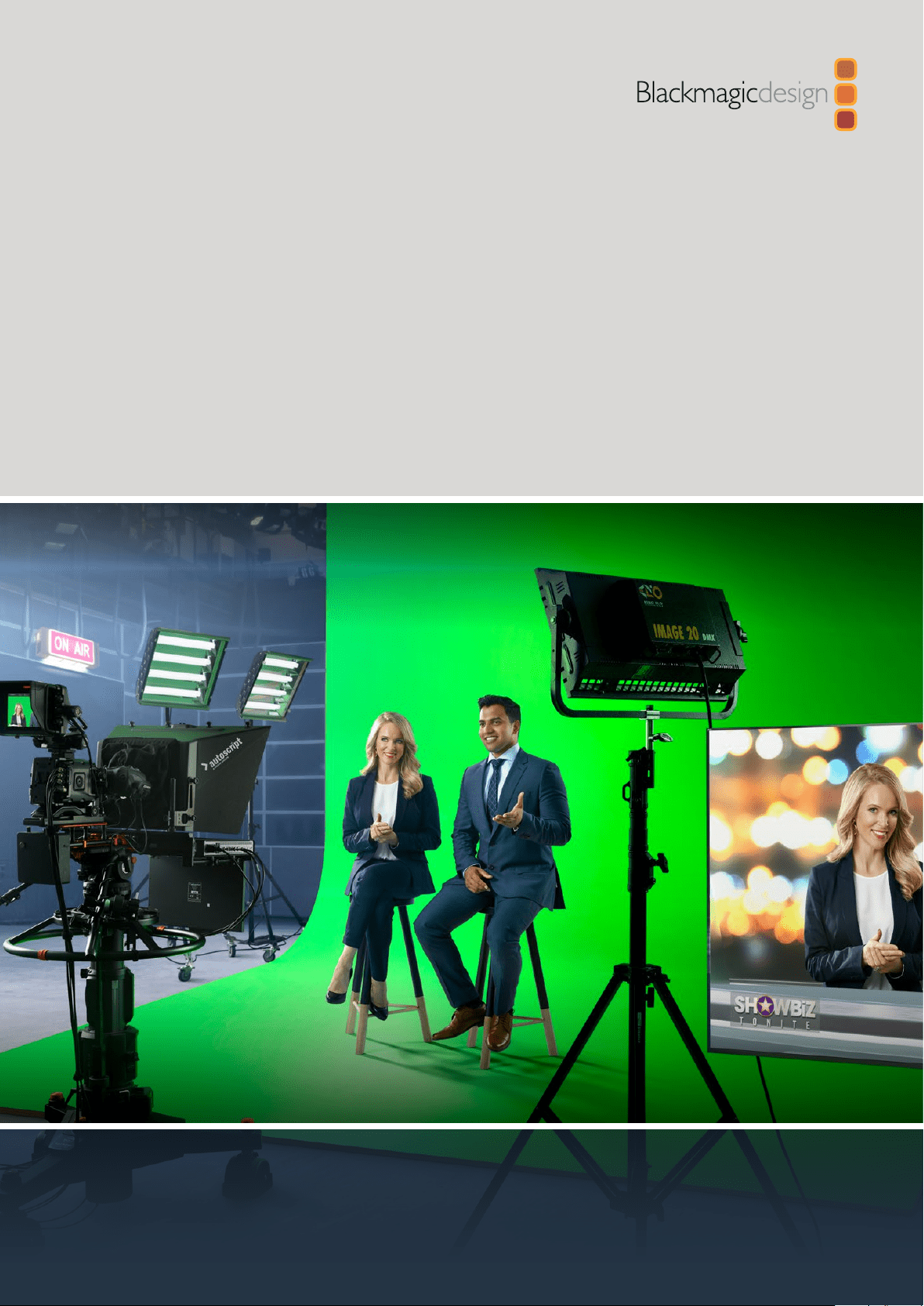
Thank you for purchasing Blackmagic Ultimatte.
Ultimatte has been the premiere keyer used in the film and television industries for
decades and no other keyer comes close to the performance that Ultimatte can achieve.
It’s powerful enough to handle fine detail on key edges as well as retaining stronger colors,
even when those foreground colors are close to the key color. Even uneven green and
blue screen backdrops can be handled.
However, what makes Ultimatte so powerful is its ability to map shadows onto the new
background layer combined with its color spill management that lets you create extremely
realistic environments. In many ways, Ultimatte is much more than a keyer as it’s really a
real time advanced compositor for creating photorealistic virtual environments. Ultimatte
lets you move your talent to any location at the click of a button and the results look real.
This instruction manual contains all the information you need to get started with Ultimatte
as well as detailed instructions on how to operate Ultimatte using Blackmagic Ultimatte
Software Control from your computer or Smart Remote 4.
Also, please check the support page on our website at
www.blackmagicdesign.com for
the latest version of this manual and for updates to your Blackmagic Ultimatte’s software.
Keeping your software up to date will ensure you get all the latest features! We are
continually working on new features and improvements, so we would love to hear from you!
Grant Petty
CEO Blackmagic Design
English

Contents
3
Introducing Ultimatte 5
What is a Matte? 5
Types of Mattes 6
Getting Started 9
Plugging in Power 9
Setting the Language 9
Connecting your Camera Foreground 10
Connecting to a Switcher 11
Monitoring 11
Setting the Auto Composite 11
Monitor Cascade 12
Connectors 13
Supported Video Formats 15
Using the Front Control Panel 16
LCD Display 16
Quick Preset Buttons 17
Menu 17
Lock 17
LCD Menu Settings 17
Setup Settings 18
Network Settings 19
Matte Status 20
Input Status 21
Reset 21
Controlling Ultimatte 22
Ultimatte Software Control 22
Installing Ultimatte Software 22
Connecting your Computer 23
Assigning a Unit Number 24
Selecting the Ultimatte Main Unit 26
Ultimatte Software Control Layout 27
Main Menu Buttons 27
Information, File Control and Auto Key 27
Groups 28
Functions 28
Status Bar 28
Monitor Out 29
Setting Controls 29
Using the Media Pool 30
Supported File Formats for Stills 31
Stills Background and Layer Options 31
Ultimatte Compositing Workflow 32
Quick Guide to Building a Composite 33
Setting the Foreground Backing Color 33
Setting Screen Correction 34
Setting the Matte Density 35
Perfecting your Composite 35
Advanced Ultimatte Controls 37
Adjusting Matte Controls 37
Adjusting Foreground Flare Controls 42
Adjusting Foreground Ambiance Controls 44
Adjusting Brightness, Color,
Contrast and Saturation
45
Additional Background Settings 47
Additional Layer Settings 47
Matte Input Settings 49
Settings 52
System 52
Media 52
Inputs 52
Outputs 53
Monitor Cascade 55
On Air Settings 55
GPI and Tally Settings 56
Monitor Out Settings 58
Presets 60
Saving and Managing Presets 60
Assigning presets 61
Importing and Exporting Presets 62
Archives 63
Ultimatte 12

4 Ultimatte 12
Creating an Archive 63
Restoring an Archive 64
Customizing the Menus 65
Camera Control via Ultimatte 12 HD Mini 66
Connecting to a Network 68
Setting the IP Address 68
Setting the IP Address for your
Smart Remote 4
69
Assigning Unit Numbers 69
Blackmagic Ultimatte Setup 71
Updating the Internal Software 72
Using Smart Remote 4 73
Connecting Power 73
Connecting to Ultimatte 73
Turning on Smart Remote 4 74
Updating your Smart Remote 4 74
Uninstalling Software 74
Installing Ultimatte Smart Remote Setup 77
Connecting a USB Keyboard and Mouse 78
Rack Installation 79
Installing Front Rack Ears 80
Installing Rear Rack Ears 80
Installing Chassis Bumpers 80
Rack Mounting 81
Developer Information 83
Controlling Ultimatte using Telnet 83
Blackmagic Ultimatte 12 Ethernet Protocol 84
Help 100
Regulatory Notices and
SafetyInformation 101
Warranty 102
Introducing Ultimatte
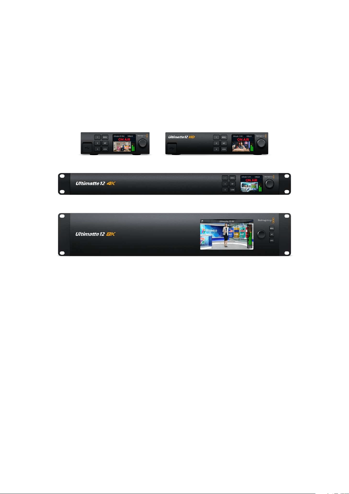
Ultimatte is a family of advanced professional real time compositors forHD, Ultra HD and 8K
liveproduction. All Ultimatte models share the same powerful keyer functions and can be
controlled from your computer using the Ultimatte Software Control application, or by using
aSmart Remote 4 hardware control panel.
This instruction manual will show you the different types of mattes used when building your
composite, including what they are and how they work, plus provides all the information you
need to get started with your Ultimatte and master all the controls and features!
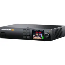
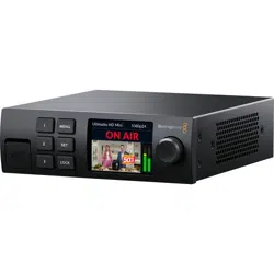
Ultimatte 12 HD Mini Ultimatte 12 HD
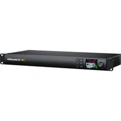
Ultimatte 12 4K
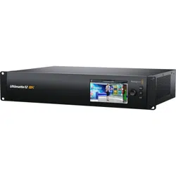
Ultimatte 12 8K
What is a Matte?
Before we get started using Ultimatte, it’s a good idea to look at the types of mattes you can
use and how they are arranged in your composite. A basic knowledge of matte types will let
you jump right in and start refining your composite.
When a section of an image is intended to be composited over another image, it requires
an accompanying matte, either generated internally by Ultimatte, or supplied via an external
source. A matte is also known as an ‘alpha’, or ‘key’, and is displayed as a grayscale image.
The matte determines what will be visible in the accompanying source image that is being
composited. The source image to be composited is called the ‘fill’.
Black regions in the matte will allow those regions in the corresponding ‘fill’ image to be visible
in the composited output, and any areas that are white will be cut out, or removed, showing the
image behind it. Variations of gray means those areas of the corresponding fill image will be
partially transparent.
5What is a Matte?
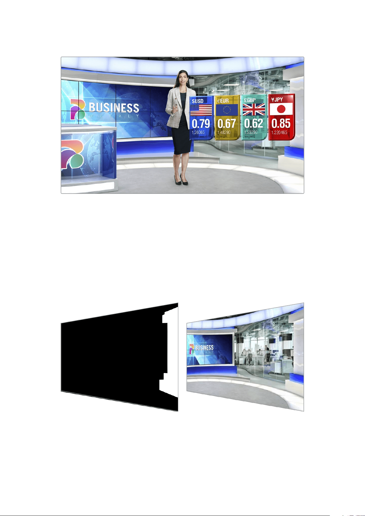
An example of a final output comprised of background, foreground and layers composited together
Types of Mattes
Different matte types are used for specific purposes to separate areas of the corresponding
image into foreground and background elements, or to include or exclude sections of the matte
you want to keep or discard.
Below is a description of the types of mattes used.
Background Matte
The background matte lets you extract a section from the background and place it over
theforeground.
For example, you may have a virtual set as your background image that has a partition on one
side. Using a background matte that precisely matches the partition in your virtual set, you can
extract the partition from the background and the talent can walk behind it. This is an excellent
way to create a foreground element using the background image and keeps the layer input free
for additional foreground items. It’s important to note that elements to be extracted from the
background must be completely opaque.
6What is a Matte?

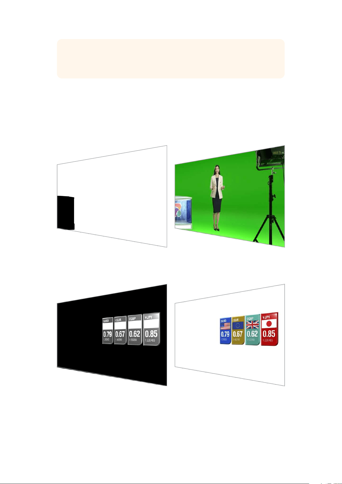
Matte
This is the primary matte you will be working within your composite. This matte is derived using
the source connected to the foreground input. Typically a presenter in front of a green screen.
The matte is generated internally by analyzing the backing color in the source video and will
determine what is visible in the foreground image.
TIP Objects that obscure the backing color, either partly or completely, will be visible in
the composited image. In the matte, fully opaque black means the corresponding areas
in the fill image will be completely visible. Shades of gray means partially transparent.
Garbage Matte
A garbage matte excludes areas of a source you don’t want to include in your composite.
For example, there may be lights and gripping equipment visible around the edges of your
foreground image. If you want to mask out these unwanted areas, a garbage matte lets you
do that. Garbage mattes can be generated externally so they precisely match shapes in your
source video, and connected to the garbage matte input.
7What is a Matte?
TIP You can create an internal mask using the ‘window’ controls on your Ultimatte.
This can be a great tool for creating a rough, fast garbage matte. For more information
on how to set up window masks, refer to the ‘matte input/window’ section.
Holdout Matte
This matte is similar to a garbage matte, however, it lets you mask out areas from within the
visible foreground so they are ignored by the matte.
For example, imagine a portion of a virtual set needs to appear green in the foreground.
This will present a challenge because anything green will key out and reveal the background
underneath. A holdout matte can be created to exclude that particular area within the set, which
will prevent it from being keyed.
Layer Matte
The layer matte lets you add more foreground elements to the scene. For example, if you want
to add graphics over the top of the composite.
The layer matte can include transparency elements and you can swap the layer positioning
in the final composite. For example, you may want to change the layer order during your
production so the layer input appears in front of, then behind, the talent. You can even set
atransition rate so the order change is a smooth mix transition.
For more information, refer to the ‘Matte input settings/setting the layer order’ section.
8What is a Matte?
Getting Started
Getting started with your Ultimatte is as simple as plugging in power, plugging in your
camera foreground, connecting your background source and then plugging the automatically
generated composite into a switcher. This getting started section will show you the basics of
setting up a fast auto composite for your live production. The model used in this section is an
Ultimatte 12 HD Mini which has HDMI connectors, but all SDI Ultimatte models share similar
features and the setup is exactly the same for their SDI connectors.
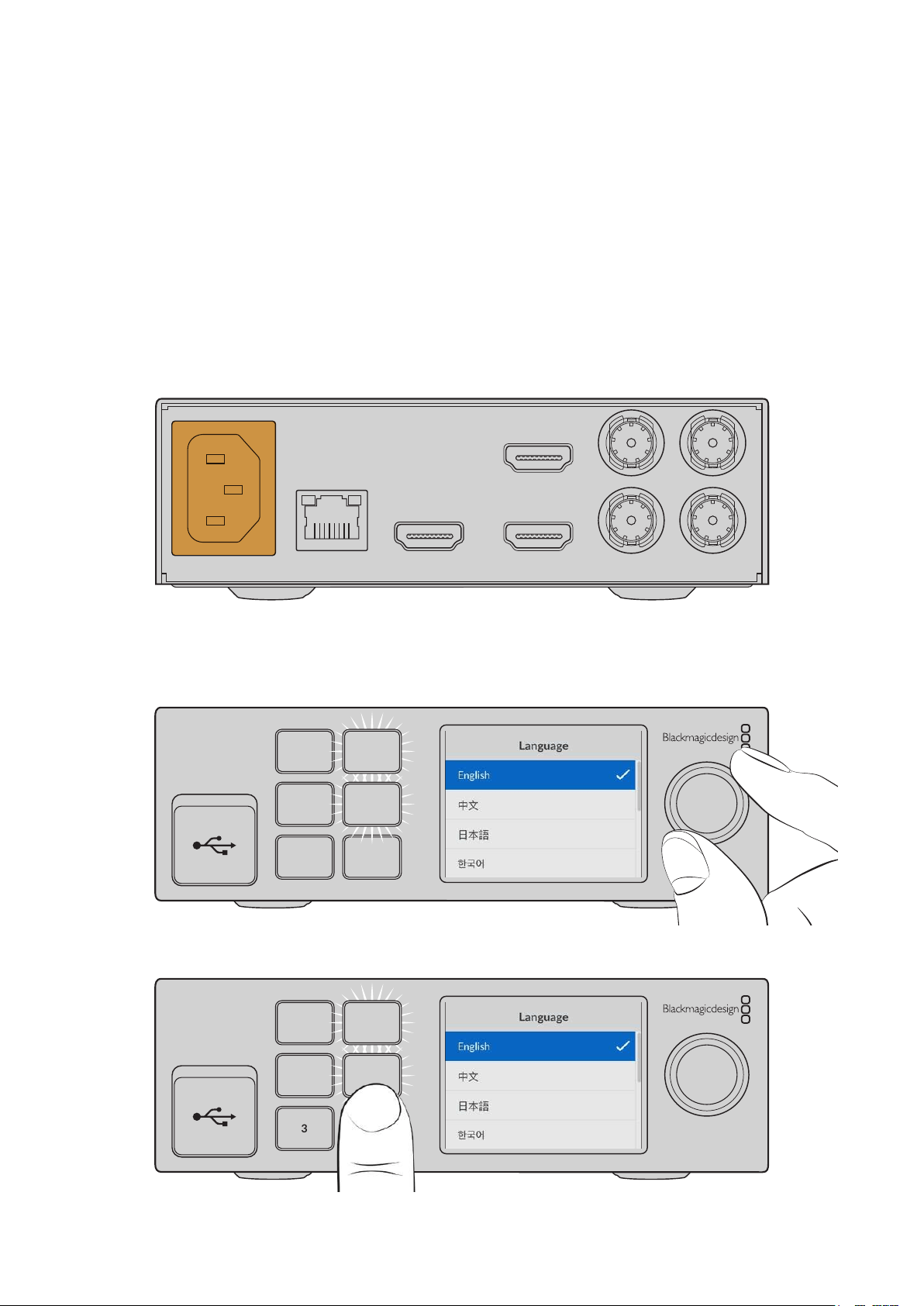
Plugging in Power
To power your Ultimatte, plug a standard IEC cable into your Ultimatte’s power input on the
rear panel.
BACKGROUND
CAMERA FG
PGM OUT PGM OUT MON OUT
RETURN MON IN
ETHERNET
Setting the Language
Once powered, the LCD display will prompt you to select your language. Using the settings dial,
scroll to the language you wish to use and press the flashing ‘set’ button to confirm your selection.
1
2
3 LOCK
SET
MENU
1 Use the settings dial to select your language
1
2
3 LOCK
SET
MENU
2 Press the ‘set’ button to confirm your setting
9Getting Started

Connecting your Camera Foreground
With power connected, you can now plug your camera into the camera foreground input.
BACKGROUND
CAMERA FG
PGM OUT PGM OUT MON OUT
RETURN MON IN
ETHERNET
Connecting the Background
Now plug your background source into the ‘background’ input. Forexample, this could be
a video feed from a gaming console, oravirtual set from a HyperDeck video feed, or even
a still graphic you can load into the media pool using Ultimatte Software Control. For more
information, refer to the ‘using the media pool’ section.
BACKGROUND
CAMERA FG
PGM OUT PGM OUT MON OUT
RETURN MON IN
ETHERNET
Generating an Auto Composite
As you plug in your sources, Ultimatte will automatically build your composite and you can
see it happening on the front panel’s LCD. Once all sources are connected, the automatically
generated composite is ready for output.
1 MENU
2 SET
3 LOCK
NOTE The foreground input will determine the video format for all inputs. For example,
if you have 1080 HD connected to the foreground input, make sure all the other
sources are set to 1080 HD.
10Getting Started
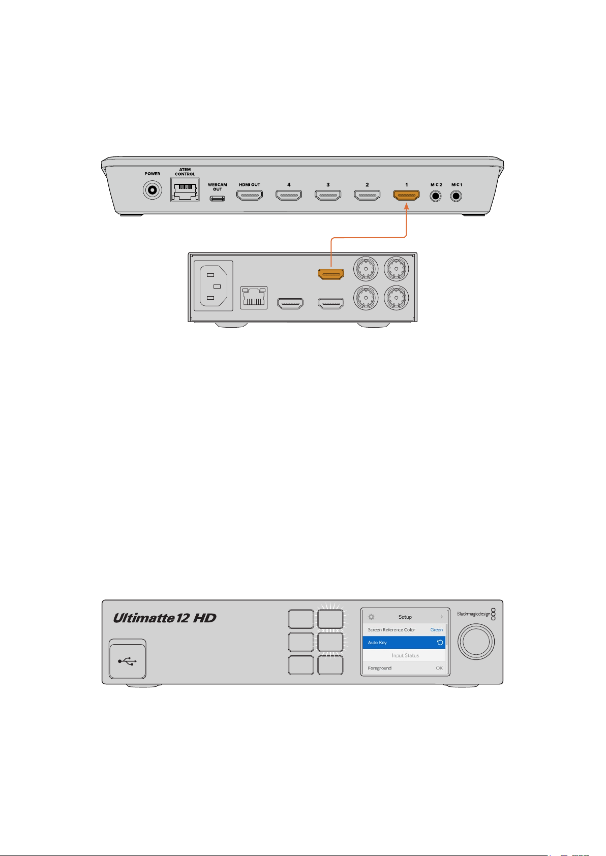
Connecting to a Switcher
The program video output lets you connect the final composite to an ATEM switcher, for
example an ATEM Mini or ATEM SDI. If your foreground input source has embedded audio
andtimecode, they will be included in the program output.
ATEM Mini
Ultimatte 12 HD Mini
BACKGROUND
CAMERA FG
PGM OUT PGM OUT MON OUT
RETURN MON IN
ETHERNET
Connect your Ultimatte’s program output to an ATEM switcher
Monitoring
Plugging a monitor into the monitor output lets you view the background source, camera
foreground and internally generated mattes. This is helpful when refining your composite.
For more information refer to the ‘monitor out’ section.
The monitor input and output is also used for cascade monitoring. This feature lets you daisy
chain multiple Ultimatte units via SDI so you can monitor the sources and outputs on all units
via one single Ultimatte, rather than connecting monitors to each unit individually. For more
information, refer to the ‘monitor cascade feature’ section.
Setting the Auto Composite
The automatically generated composite is ready to be used as soon as your foreground and
background sources are connected. You can reset the starting composite at any time by using
the ‘auto key’ function in the front panel’s LCD menu. We recommend resetting the auto key
each time the lighting changes or you shift the camera’s position.
2
1 MENU
SET
3 LOCK
Use the auto key function to reset your composite
Your Ultimatte will set an automatic composite with green selected as the backing color by
default. If your lighting is optimized and your green screen environment has been carefully set
up, the automatic composite generated by Ultimatte can be all you need to do.
11Getting Started

If you are setting up a highly detailed and complex virtual set, or your green screen requires
some help from Ultimatte, you can use Ultimatte Software Control on your computer or a Smart
Remote 4 hardware panel to make precise adjustments to the various matte controls and hand
craft your final composite. This includes features such as screen correction which can help
improve your composite if your green screen has uneven lighting or blemishes that are visible
in your auto key.
We believe you will enjoy exploring your Ultimatte and developing your own workflow to
produce amazing virtual environments. You can even build larger setups using multiple
camerasand an Ultimatte unit on each camera so you can have different camera angles on
your virtual set. When constructing graphics and backgrounds that are tailored to each angle,
the possibilities are truly endless!
Please keep reading this manual for information on how to use your Ultimatte’s front panel to
change settings, plus how to control the unit using Ultimatte Software Control.
Monitor Cascade
The monitor cascade feature lets you view the monitor output from up to eight Ultimatte units
via one single unit.
To connect up to eight Ultimatte units together and use the monitor cascade feature, each
unit needs to be connected to common analog reference or to foreground sources that are
locked together. The Ultimatte units can then be daisy chained via their monitor inputs and
outputs, with the last unit plugged into a monitor. Then when you select any of the eight units
in Ultimatte Software Control, the monitor output for that particular unit can be viewed from the
monitor output on thelast unit.
To enable the monitor cascade feature in Ultimatte Software Control, click on the ‘info’
icon in the files and information section, and check the ‘monitor cascade’ checkbox in the
‘configuration’ tab.
Switching the monitor cascade feature on or off will affect the SDI monitor output but does not
affect your Ultimatte’s front panel LCD. The LCD on the front panel always displays the program
output for that unit.
Below is an example showing how two Ultimatte units are daisy chained for cascade monitoring.
LOOP
IN
LOOP
IN
LOOP
IN
LOOP
IN
LOOP
IN
GPIO BG FGBG MATTE
LOOP
IN
LOOP
IN
LAYER LAYER MATTEH MATTE
USB
ETHERNET
OUT
IN
REF FILL MATTE
1
2
1
2
1
2
PGM
1
2
TALENT
OUT
IN
MONITOR
LOOP
IN
AC IN G MATTE
INPUTS
OUTPUTS
LOOP
IN
LOOP
IN
LOOP
IN
LOOP
IN
LOOP
IN
GPIO BG FGBG MATTE
LOOP
IN
LOOP
IN
LAYER LAYER MATTEH MATTE
USB
ETHERNET
OUT
IN
REF FILL MATTE
1
2
1
2
1
2
PGM
1
2
TALENT
OUT
IN
MONITOR
LOOP
IN
AC IN G MATTE
INPUTS
OUTPUTS
INPUT DISP
H/V
DELAY
3D
LUT 1
BLUE
ONLY
ZOOM PEAK
3D
LUT 2
H
MARK
V
MARK
Reference
Ethernet
For more information on cascade monitoring, refer to the ‘settings/monitor cascade’ section.
12Getting Started

Connectors
Use the connectors on your Ultimatte’s rear panel to connect power, video inputs, video
outputs and to connect your Ultimatte to a computer or network. On smaller units that have
fewer inputs you can load stills into the media pool and assign them to specific sources instead
of plugging in those sources via a connector. Refer to the ‘Using the Media Pool’ section for
more information.
LOOP
IN
LOOP
IN
LOOP
IN
LOOP
IN
LOOP
IN
GPIO BG FGBG MATTE
LOOP
IN
LOOP
IN
LAYER LAYER MATTEH MATTE
USB
ETHERNET
OUT
IN
REF FILL MATTE
1
2
1
2
1
2
PGM
1
2
TALENT
OUT
IN
MONITOR
LOOP
IN
AC IN G MATTE
INPUTS
OUTPUTS
1 2
3 4
5
6 7 8
Ultimatte 12 4K
Ultimatte 12 HD Mini
1
3 6
7
8
BACKGROUND
CAMERA FG
PGM OUT PGM OUT MON OUT
RETURN MON IN
ETHERNET
1 Power
Power your Ultimatte by connecting a standard IEC cable to the rear panel. If your
Ultimatte model has an additional IEC power input, you can connect to another power
source for redundancy. For example, connecting the second input to an uninterrupted
power supply, or UPS, will instantly take over if the primary source fails.
2 USB
On larger Ultimatte units, use the USB port on the rear panel to connect your
Ultimatte to your computer. This allows you to update and configure your Ultimatte
with Blackmagic Ultimatte Setup. On smaller Ultimatte models the USB port is on the
front panel.
3 Ethernet
The Ethernet port lets you connect to a computer, network or Smart Remote 4 so you
can control your Ultimatte using Ultimatte Software Control. For more information,
refer to the ‘connecting your computer’ and ‘connecting to a network’ sections later
inthis manual.
4 Reference
Most Ultimatte models feature reference input and output connectors. You can connect
a reference signal to the reference input and sync your Ultimatte to an external master
sync source. The reference out lets you loop the reference input to another Ultimatte
orvideo equipment.
5 GPIO
On larger Ultimatte models, this connector is for use with an external GPI interface.
GPI inputs and outputs let you trigger Ultimatte preset files as GPI events. For more
information refer to the ‘GPI and tally settings’ section.
13Connectors

6 Video Inputs
Each source input used in a composite should be carefully planned, so the elements
that build your shot can be arranged into specific layers. Each source should be the
same video format and connected to its determined source input so you always know
where everything is, and you can manage your composite more effectively.
All inputs and outputs support SD and HD. Ultimatte 12 and Ultimatte 12 4K support
Ultra HD. Ultimatte 12 8K has additional support for 8K formats.
Background Input
The background input is the image you want to use as the background for your
composite. Depending on the Ultimatte model you are using, plug the background
input into the BG IN or Background connector. You can also select a still from the media
pool to use as a background.
Background Matte Input
If you want to extract a section of the background to use as a foreground element,
choose a still from the media store or plug the background matte source into the
BGMATTE IN connector.
Garbage Matte Input
A garbage matte allows you to exclude areas of a source so they are not included in
your composite, for example lights or gripping equipment visible around the edges of
your foreground image. To add a garbage matte plug a source containing an externally
generated garbage matte into the G MATTE IN connector. You can also select a still
from the media pool to use as a garbage matte.
Camera Foreground Input
Plug the foreground image you want to composite over the top of the background into
the FGIN or Camera FG connector. The foreground image is typically the talent in front
of a green screen.
Holdout Matte Input
A holdout matte lets you define an area of the foreground that you do not want to be
keyed out, for example a green logo on the front of a desk. To add a holdout matte
select a still from the media pool or plug a source containing an externally generated
holdout matte into the H MATTE IN connector.
Layer Input
The layer input is for any additional video or graphics you want to add to your composite.
Youcan also select a still from the media pool to use as a layer.
Layer Matte Input
Similar to other matte inputs, this input lets you connect an externally generated matte
so you can precisely add the layer input source into your composite. You can also
select a still from the media pool to use as a layer matte.
Return
The ‘return’ connector on the rear panel of Ultimatte 12 HD Mini is for connecting camera
control and tally data from an SDI ATEM switcher. For more information, refer to the
‘Camera Control via Ultimatte 12 HD Mini’ section for more information.
Monitor Input
The monitor input is important for daisy chaining to other Ultimatte units when using the
powerful monitor cascade feature. Refer to the ‘settings’ section for more information.
14Connectors

7 Video Outputs
Source Loop Outputs
On some Ultimatte models, each source input has its own dedicated loop SDI output.
Program Outputs 1 and 2
Plug a program output, marked PGM into a switcher, for example an ATEM Mini
or ATEM SDI.
Ultimatte 12 HD Mini models have both an SDI and HDMI program output.
Fill Outputs 1 and 2
If the Ultimatte unit you are using features fill outputs, then you can connect these
outputs into a recording deck, and into a switcher for final compositing.
Matte Outputs 1 and 2
If the Ultimatte model you are using has matte outputs, then you can plug these into
arecording deck, and into a switcher for final compositing. The matte output includes
the internal matte, plus the garbage matte and holdout matte if enabled.
Talent Out 1 and 2
The talent output on larger Ultimatte models lets your talent monitor the final composite
so they can position themselves in the frame and coordinate their actions to the
composited image.
The talent output has a ‘mirror’ setting that lets you flip the talent output horizontally.
Using this feature, the talent can see his or her position on the screen without needing
to compensate for reversed camera left and right staging. Refer to the ‘settings/talent
mirror’ section for more information.
8 Monitor Output
Plug the monitor output into a monitor or recording deck, the monitor output can be
used to view any of the inputs, outputs or internal matte signals. This connector isalso
used for daisy chaining to other Ultimatte units when using the powerful monitor
cascade feature. Refer to the ‘settings’ section for more information.
Supported Video Formats
All inputs and outputs support SD and HD. Ultimatte 12 and Ultimatte 12 4K support Ultra HD.
Ultimatte 12 8K has additional support for 8K formats.
Connection Types Formats
SD SDI or HD-SDI 625i50 PAL, 525i59.94 NTSC, 720p50, 720p59.94, 720p60,
1080PsF23.98, 1080PsF24, 1080PsF25, 1080PsF29.97, 1080PsF30,
1080i50, 1080i59.94, 1080i60, 1080p23.98, 1080p24, 1080p25,
1080p29.97, 1080p30
HDMI 625i50 PAL, 525i59.94 NTSC, 720p50, 720p59.94, 720p60, 1080i50,
1080i59.94, 1080i60, 1080p23.98, 1080p24, 1080p25, 1080p29.97,
1080p30, 1080p50, 1080p59.94, 1080p60
Level A or level B 3G-SDI 1080p50, 1080p59.94, 1080p60
6G-SDI or 12G-SDI 2160p23.98, 2160p24, 2160p25, 2160p29.97, 2160p30, 2160p50,
2160p59.94, 2160p60
Quad link 2SI 6G-SDI or
Dual link 2SI 12G-SDI
4320p23.98, 4320p24, 4320p25, 4320p29.97, 4320p30
Quad link 2SI 12G-SDI 4320p50, 4320p59.94, 4320p60
15Connectors

Using the Front Control Panel
On the control panel’s LCD you can view the program output plus monitor useful information
such as audio levels, the video format and frame rate, and the name of your Ultimatte unit.
When you press the menu button the settings menu will appear where you can change settings
and check the connection status on all inputs. The three numbered buttons let you instantly
recall presets.
This section provides a brief overview of the features included on the front panel.
1 MENU
2 SET
3 LOCK
LCD Display
Depending on the Ultimatte 12 model you are using, the LCD displays the program output and
the following information.
1 MENU
2 SET
3 LOCK
Format Indicator
Displays the current
video format.
Program Output
Displays the
program output.
Name
Displays the name
ofyour Ultimatte. If you
have set acustom name
it will appear here.
On Air Status
A red on air indicator will be
displayed when your Ultimatte
is switched to air. When the unit
is connected and ready to go on
air ‘standby’ will be displayed.
‘No Cam’ will be displayed if a
camera is not connected to the
foreground input.
Audio Meters
Displays the
foreground source
audio levels.
NOTE Ultimatte 12 HD Mini receives on air tally status from an ATEM switcher
connected via the HDMI PGM or SDI Return connectors. Refer to the ‘CameraControl
via Ultimatte 12 HD Mini’ for more information.
Larger Ultimatte models detect tally via the GPIO connector on the rear panel when
connected to a third party GPI interface. For more information, refer to the ‘GPI and
Tally Settings’ section.
16Using the Front Control Panel

USB
If your Ultimatte has a USB connector on the front panel, you can use this
port to connect the unit to your computer. This USB-C port is used for
updating and configuring the unit with Blackmagic Ultimatte Setup. On larger
Ultimatte models the USB-C port is on the rear panel.
Quick Preset Buttons
The three numbered buttons on the front panel are used to recall quick presets. If a quick
preset is available the corresponding button is illuminated green, when a quick preset is active
the button will be blue.
For more information, refer to the ‘presets’ section later in this manual.
Menu
Press the ‘menu’ button to open and close the settings menu.
Lock
Press and hold the ‘lock’ button for 1 second to lock the front panel. This disables the buttons,
preventing anyone from accidentally changing any settings. The button will illuminate red
when active.
Press and hold for 2 seconds to unlock the panel.
LCD Menu Settings
All the settings for your Ultimatte are located under the main ‘setup’ page. Simply scroll through
the setup menu to find the settings you need to change. These include network and matte
settings, checking the status of connected inputs, appearance settings and resetting the unit to
factory settings.
Press the ‘menu’ button on the front panel to open the menu settings.
2
1 MENU
SET
3 LOCK
17LCD Menu Settings

Rotate the settings dial to scroll through the menu.
2
1 MENU
SET
3 LOCK
With a menu item selected, press the ‘set’ button.
2
1 MENU
SET
3 LOCK
Adjust settings using the settings dial and confirm them by pressing the ‘set’ button.
Press‘menu’ to return to the home screen.
Setup Settings
The setup settings allow you to change your Ultimatte’s language selection, select the default
video standard and change the appearance of the LCD display.
Name
When more than one Ultimatte is on the network, you may wish to give them discrete names.
This can be set using Blackmagic Ultimatte Setup.
18LCD Menu Settings

Language
Blackmagic Ultimatte supports 13 languages, including English, Chinese, Japanese, Korean,
Spanish, German, French, Russian, Italian, Portuguese, Turkish, Ukrainian and Polish.
To select the language:
1 Scroll the search dial down to select language and press set.
2 Use the settings dial to select the language and press set. Once selected you will
automatically return to the setup menu.
Software
Displays the current software version for your Blackmagic Ultimatte.
Front Panel
Set your Ultimatte’s front panel to ‘light’ mode for a brightly illuminated LCD. Use ‘dark’ mode for
dimly lit environments where a bright LCD may be distracting, for example when mounted in a
rack in a production facility.
Default Standard
When set to ‘auto’ the camera or source connected to your Ultimatte’s foreground input will
determine the video format for all other inputs and all outputs.
You can choose another video format from the default standard menu. This can be useful when
you first turn on your Ultimatte without a foreground input, so all the outputs will be set to that
default video standard.
Network Settings
The network settings allow you to change your Ultimatte’s IP address, subnet mask and
gateway settings. You can also switch between network protocols.
Protocol
Your Ultimatte unit is shipped with a default IP address of 192.168.10.220 but you can change
this address if you want to connect to a network. This is also important when sharing multiple
Ultimatte units on your network and controlling them using Ultimatte Software Control.
19LCD Menu Settings

IP Address, Subnet Mask and Gateway
Once Static IP is selected, you can enter your network details manually.
To change the IP address:
1 Use the settings dial to highlight ‘IP address’ and press the flashing ‘set’ button on
yourUltimatte’s front panel.
2 Rotate the settings dial to adjust your IP address, pressing ‘set’ to confirm before
adjusting the next set of values.
3 Press ‘set’ to confirm the change and move to the next value.
When you have finished entering your IP address, you can repeat these steps to adjust the
Subnet Mask and Gateway. Once finished, press the flashing ‘menu’ button to exit and return
tothe home screen.
DHCP
You can also enable DHCP instead of assigning an IP address manually.
DHCP is a service on network servers that finds your Ultimatte and assigns an IP address
automatically. DHCP makes it easy to connect equipment via Ethernet and make sure their
IPaddresses do not conflict with each other.
To enable DHCP:
With ‘protocol’ selected press the flashing ‘set’ button to access the menu, scroll to ‘DHCP’
andpress ‘set’.
Matte Status
You can use the matte status settings to change the background screen reference color
andperform an auto key of your composite.
Screen Reference Color
Use this option to select the color of your background. The default color is green.
Auto Key
Use the auto key function to perform a quick composite of your scene. Refer to the ‘setting the
auto composite’ section for more information.
20LCD Menu Settings

Input Status
The input status display lets you quickly check and confirm which inputs are connected to your
Ultimatte and if they are functioning correctly.
If ‘OK’ is displayed next to input, then your Ultimatte is receiving an input correctly. If ‘no input’
isdisplayed and you have an input connected, check that your cables are connected correctly
and that the input format matches the foreground.
Reset
Highlight ‘factory reset’ in the setup menu to restore your Ultimatte to factory settings.
Once you press ‘set’, you will be prompted to confirm your selection. Your Ultimatte erases all
settings, presets and the contents of the media pool.
Before performing a factory reset you can export individual presets or create an archive that
will contain all presets and the contents of the media pool. Refer to the ‘presets’ and ‘archives’
sections for more information.
21LCD Menu Settings

Controlling Ultimatte
Now that you are familiar with your Ultimatte’s front panel, we can begin exploring how to
control your Ultimatte and build a composite. There are two different ways to control the unit,
such as using the Ultimatte Software Control application on a Windows or Mac computer, or by
using the touch screen interface on an optional Smart Remote 4 hardware panel. Both methods
use the same general interface so once you are familiar with one, you will also be familiar with
the other. The next section of this manual will explore Ultimatte Software Control.
Ultimatte Software Control
Ultimatte Software Control gives you full control over all the features and functions of your
Ultimatte allowing you to fine tune your composite, change settings, load images into the
media pool and control up to eight Ultimatte units over a network. Ultimatte Software Control
iscompatible with Mac and Windows computers and Smart Remote 4.
Controls and settings are changed using buttons and knobs in the general interface. The
settings for each control knob varies depending on which menu you have selected. Additional
settings are accessed from the ‘Ultimatte’ and ‘preset’ menus at the top left of the screen. If you
are using a Smart Remote 4, the physical buttons on the left side of the panel can be used to
change these additional settings.
Installing Ultimatte Software
The Blackmagic Ultimatte software includes both Ultimatte Software Control and the Ultimatte
Setup application.
Ultimatte Setup lets you update the internal software of your Ultimatte as well as change
various settings such as network protocol.
For information on installing Ultimatte Software Control on Smart Remote 4, refer to the
‘updating your Smart Remote 4’ section.
22Ultimatte Software Control
Windows Installation
1 Download the latest version of the Ultimatte software from
www.blackmagicdesign.com/support and double click the installer file.
2 Follow the install prompts and accept the terms in the license agreement and Windows
will automatically install the software.
Click the Windows ‘start’ button and then go to All Programs>Blackmagic Design. The folder will
contain both Ultimatte Software Control and Ultimatte Setup applications.
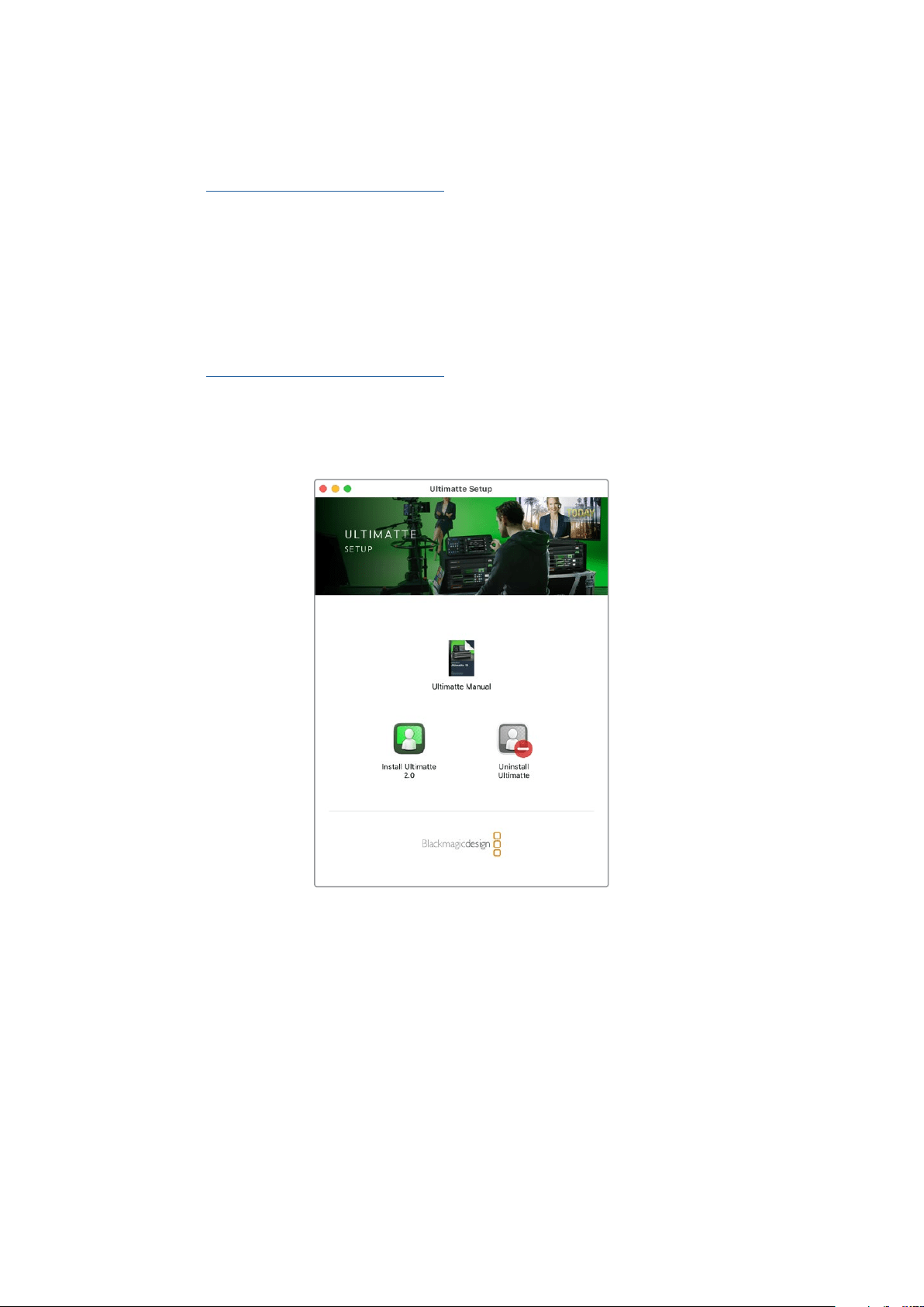
Mac Installation
1 Download the latest version of the Ultimatte software from
www.blackmagicdesign.com/support and double click the installer file.
2 Follow the install prompts and Mac OS X will automatically install the software.
A folder called ‘Blackmagic Ultimatte’ will be created within your applications folder, containing
Ultimatte Software Control and Ultimatte Setup.
To install Ultimatte Software, double click
the installer and follow the prompts
Connecting your Computer
After you have downloaded the software, connect your computer’s Ethernet port to your
Ultimatte using a CAT 6A or CAT 7 Ethernet cable. For 10G Ethernet ports, we recommend
aCAT 7 cable for maximum transfer speed.
For 1G Ethernet ports, connect to your computer using a standard CAT5e or CAT 6 cable.
ACAT6 cable will prevent any potential interference from nearby equipment.
Connecting to an Ethernet switch will allow you to control up to 8 Ultimatte units.
23Ultimatte Software Control
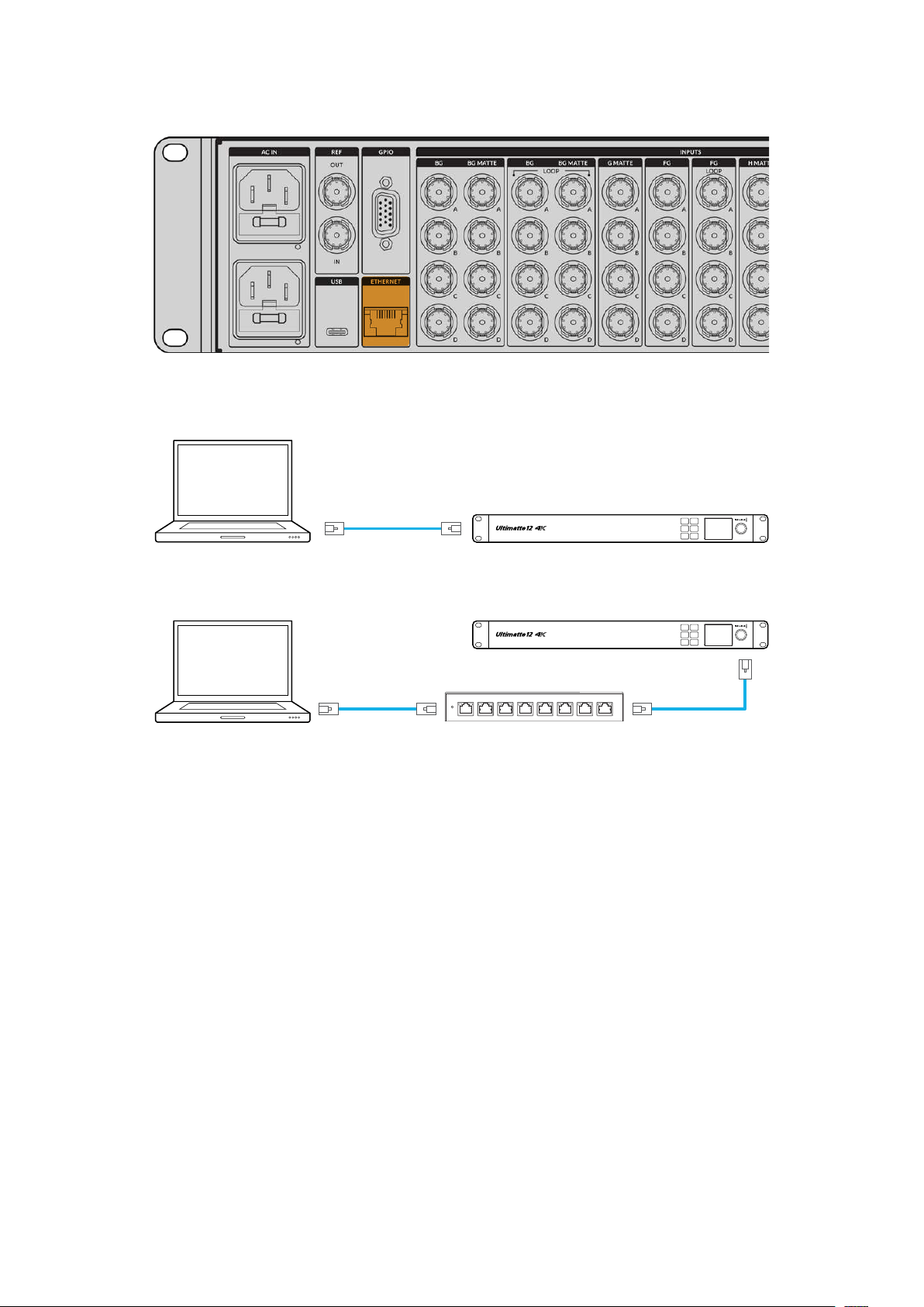
Ethernet port on the rear panel of Ultimatte 12 8K
Connecting Directly
Ethernet
Computer Ultimatte 12 4K
MENU
SET
LOCK
1
2
3
Connecting via a Network
Ethernet
Network
Ethernet
Computer
Ultimatte 12 4K
MENU
SET
LOCK
1
2
3
Your Ultimatte unit has a default static IP address of 192.168.10.220. All Ultimatte models
except Ultimatte 12 support DHCP so the unit can be found on your network automatically and
assigned an IP address. For information on how to manually set the network settings, refer to
the ‘connecting to a network’ section.
Assigning a Unit Number
Once you have connected to a computer or Ethernet switch, launch Ultimatte Software Control.
The software will automatically look for connected Ultimatte units.
When launching Ultimatte Software Control for the first time, a window will appear asking for
you to assign your Ultimatte unit to a number. This is because up to 8 Ultimatte units can be
controlled, therefore the software needs to identify each one. This only needs to happen the
first time you connect to Ultimatte Software Control. Once the unit is assigned a number, it will
be remembered the next time you launch the software.
24Ultimatte Software Control

To assign the unit:
1 Click in the list for number 1 and select your Ultimatte unit.
TIP If you are connecting to an Ultimatte 12, click the ‘add via IP’ button and
enter the Ultimatte’s IP address.
2 Click ‘save’.
Ultimatte Software Control will now display the Ultimatte controls.
25Ultimatte Software Control

You can always assign additional units by clicking on the ‘Ultimatte’ menu at the top of the
screen and selecting ‘Ultimatte Connection’.
You can see all the Ultimatte units being controlled by glancing at the status bar. Up to 8 units
can be controlled, and each unit icon will illuminate green when identified on your network.
When a unit is selected for control, the icon will illuminate blue. For more information on how to
set up and control multiple units over a network, refer to the ‘connecting to a network’ section.
Refer to the ‘connecting to a network’ section for information about how to set up and control multiple Ultimatte
units on your network
TIP If your Ultimatte is connected to your computer or Smart Remote 4 but its unit
indicator is not illuminated in the status bar, check your IP settings are configured
correctly. Refer to the ‘connecting to a network’ section for more information.
Selecting the Ultimatte Main Unit
If you are connected to more than one Ultimatte unit over a network, you can switch between
the unit you want to control by clicking the corresponding unit number in the Ultimatte
Status bar. You can also use the F1-F8 keys on your computer’s keyboard to switch between
connected Ultimatte units.
If using a Smart Remote 4 to control more than one Ultimatte, use the ‘units’ buttons on the left
hand side to select the Ultimatte you want to control. Tapping the numbers in the status bar will
launch the connection dialogue box.
When selected, the unit icon will illuminate blue and all controls will be visible.
26Ultimatte Software Control
Ultimatte Software Control Layout
Settings and controls are displayed in sections. Although the interface can look intimidating
at first glance with all the different buttons and settings, it won’t take long before you will be
moving between settings instinctively as you build your composite.
When you first look at the interface you can see a main menu at the top with a menu information
bar underneath. Below that, the panels are separated into sections labeled ‘groups’, ‘functions’
and ‘monitor output’. As you choose the menu and then move through the functions and groups,
the sections will populate with relevant settings letting you navigate quickly between them.
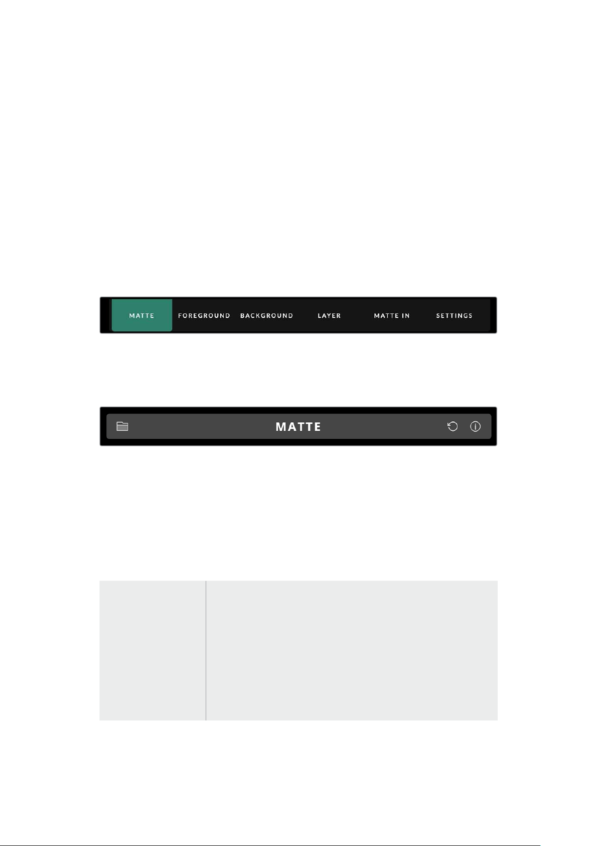
Main Menu Buttons
Use the menu buttons along the top of the screen to select the different input sources you want
to adjust, plus select the matte for making adjustments to the primary matte, and generally
configure your Ultimatte.
Information, File Control and Auto Key
This section of the interface lets you save and access preset files, set an auto composite and
configure certain settings for your Ultimatte.
Click on folder icon to manage preset and archive files, you can use the dialogue box to
save, load, import and export presets. Refer to the ‘presets’ and ‘archives’ section for more
information.
Use the auto key button to set an auto composite. For more information on setting an auto
composite, refer to the ‘setting the auto composite’ section for more information.
To view status information and various configuration settings for your Ultimatte, click on the
information icon.
The available information and configuration settings are described below:
About Displays detailed status information about your Ultimatte including the
model name, software version, video format and network settings.
If you are using a Smart Remote 4, additional information is included,
suchas:
Remote version
Flash version
Temperature
Fan speed
Blackmagic Design contact information should you need support.
27Ultimatte Software Control Layout
Configuration Provides an overview of connected input sources and will tell you whether
they are locked or not.
Control Board Settings Lets you customize the brightness of the Smart Remote 4’s LEDs and set
the internal fan speed.
Options Turns the mouse pointer on or off if you have a mouse connected to Smart
Remote 4.
Monitor Cascade Enables the monitor cascade feature.
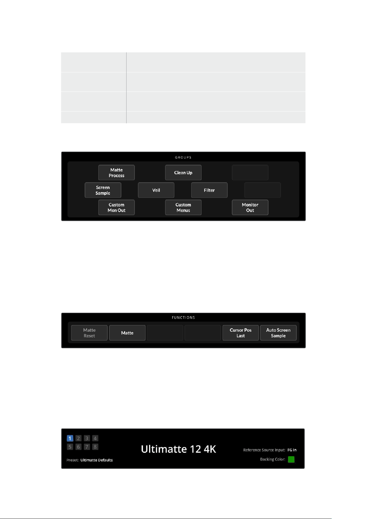
Groups
This section of the interface contains the majority of the settings menus. For example, if you
wanted to adjust the foreground ‘flare’ controls:
1 Click on the ‘foreground’ main menu button to open the foreground settings.
2 Click on the ‘Flare 1’ button in the groups section to select the flare controls.
The flare controls will now be visible on each side of the panel and you can adjust them using
the control knobs.
Functions
The functions section provides specific settings that can be selected, enabled or disabled.
For example, the matte reset button is located in this section if you need to restore particular
settings to their default state.
Status Bar
You can see all the Ultimatte units being controlled by Ultimatte Software Control by glancing at
the status bar. Up to eight units can be controlled, and each unit icon will illuminate green when
identified on your network. When a unit is selected for control, the icon will illuminate blue.
28Ultimatte Software Control Layout
Ultimatte Main
UnitIndicators
The eight small box indicators on the left side show you which main
units are connected on the network, and which unit is currently being
controlled. If tally is connected via the GPIO input, the boxes will illuminate
red when a unit is on air.
Reference Source
Input
Displays the current reference source connected to your Ultimatte.
Thereference signal can befrom the foreground source connected to
theforeground input, or via the reference input. Ifa reference source is
absent, ‘none’ will be displayed.
Backing Color The default backing color is green and will be reflected by this indicator.
When the backing color is changed, the indicator will also change to show
the backing color being used.
Preset When you have loaded a preset file using the information and file control
section, the preset name will be displayed. If no preset is loaded, ‘ultimatte
defaults’ will be displayed.
In addition, the status bar also notifies you with messages. For example,
if a specific control is currently locked and you need to enable another
setting to access it, the status bar will notify you.
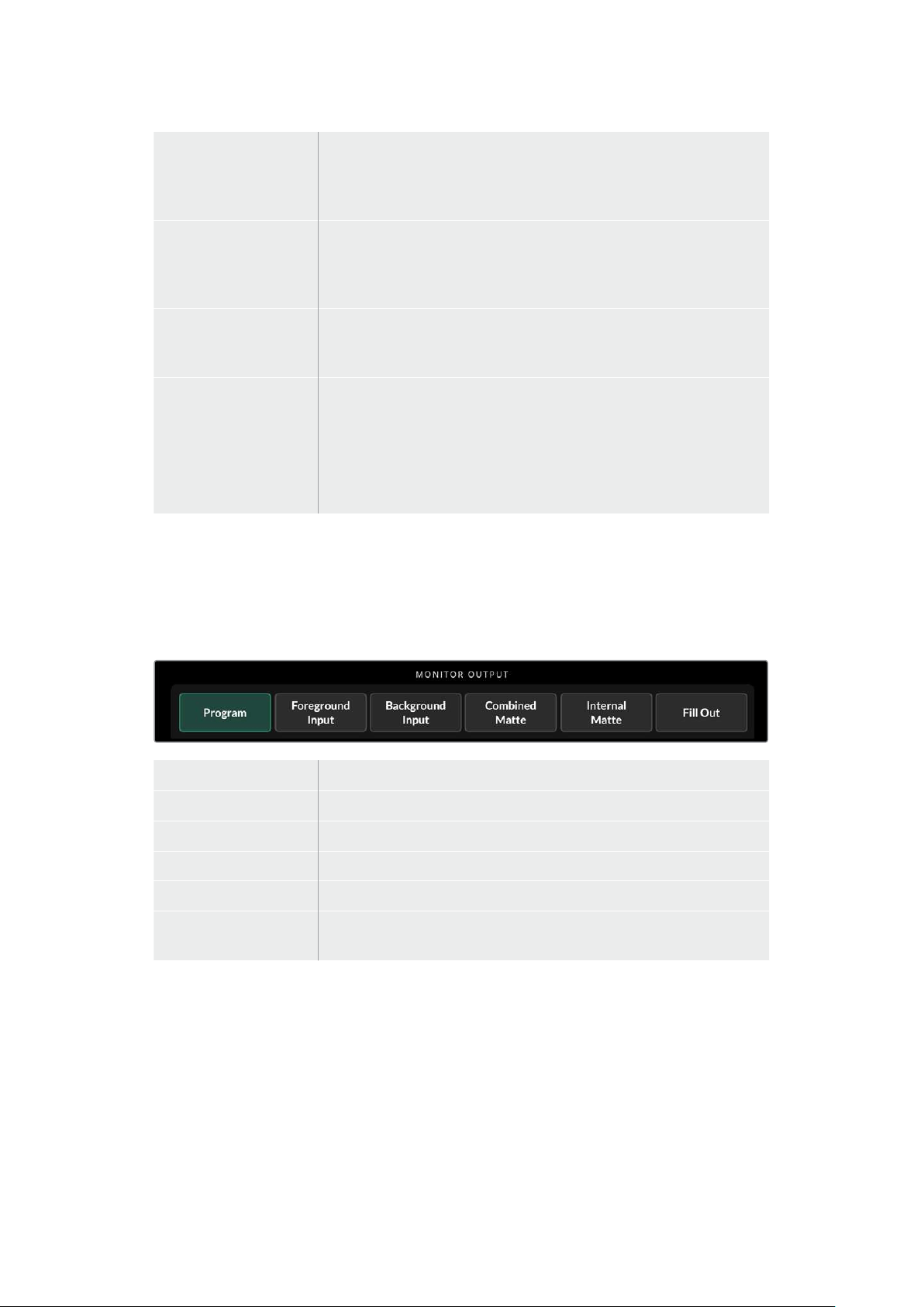
Monitor Out
The buttons in this section of the interface will select one of six images to be displayed on a
video monitor connected to your Ultimatte’s monitor output.
The default selections are listed below.
Program Final composited image.
Foreground Input Source image connected to the foreground input.
Background Input Source image connected to the background input.
Combined Matte Internal Matte + Garbage Matte + Holdout Matte.
Internal Matte The internal matte created by Ultimatte.
Fill Out Foreground image with spill removed, colorizers added, and the screen
color suppressed to black.
Setting Controls
On each side of the interface, you can see a row of setting control knobs. These control knobs
will change based on which menu, group and function you have selected.
To adjust a setting, click on a control knob and move your mouse left or right. You can also click
in the box below the settings knob and enter a number using your keyboard.
Double click a settings knob to return it to its default position.
29Ultimatte Software Control Layout
Using the Media Pool
The media pool lets you store images and assign them as sources for your composite. You can
also add transitions between two still images when they are assigned as a background and
background matte or layer and layer matte.
This section shows how to load stills and assign them as sources.
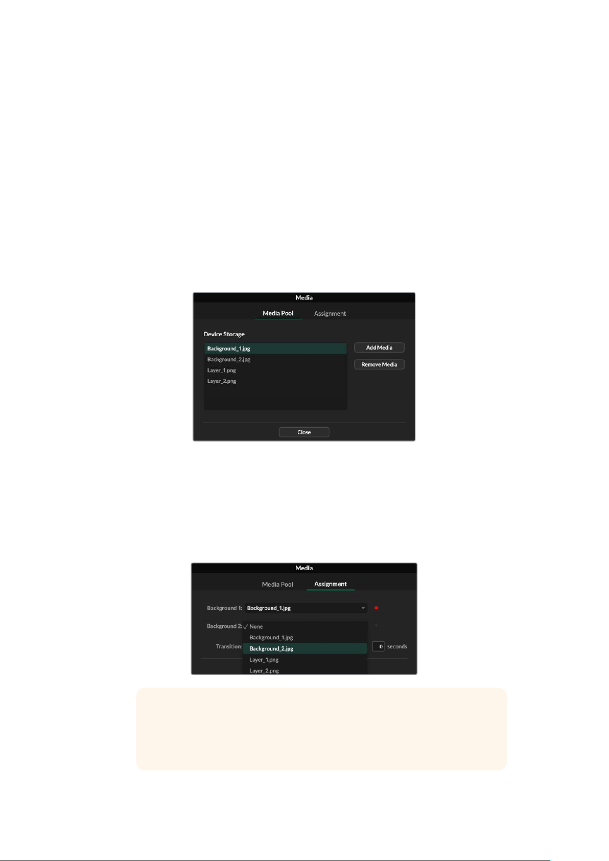
To load a still into the media pool:
1 Open the ‘settings’ tab in Ultimatte Software Control and click on the media button.
2 Choose ‘media setup’ from the groups area to open the media pool dialogue box.
3 Click the ‘add media’ button in the media pool tab and choose the image you want
to import.
4 Your imported image will now appear in the device storage list.
Imported images will appear in the device storage list
To delete an imported image, simply select it from the list and click on the ‘remove
media’ button.
To assign a still image to a source:
1 Select the assignment tab in the media window.
2 Use the destination menu to assign a still image to a background, layer or matte.
TIP A small red dot to the right of the assignment menu indicates that an
image is the current selected source for a background or layer. This helps to
make sure that you don’t accidentally change a still which is currently on air
and makes it easy to identify which still will be used for the next transition.
30Using the Media Pool
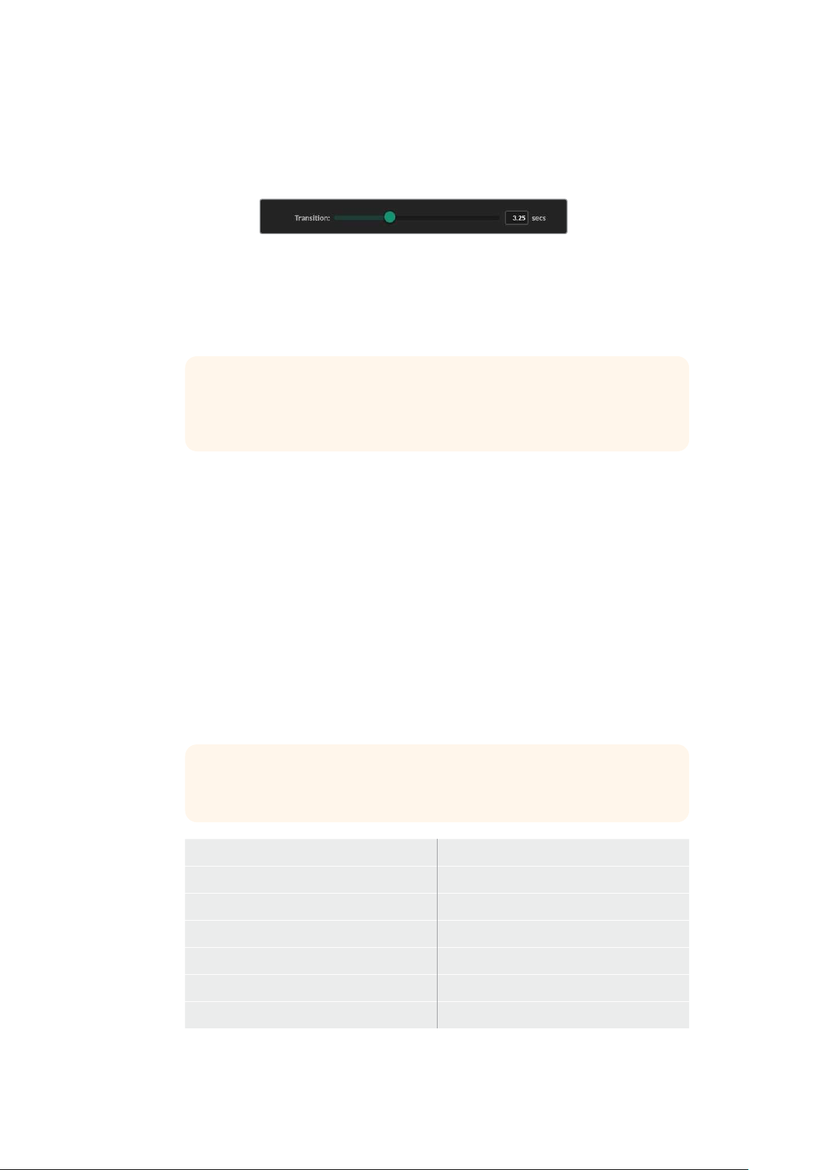
3 If you are using still images for both the background or layer destinations, then you
can choose to add a dissolve transition between the two images. To set the duration
of the transition use the transition slider. Dissolve transitions can be between 0 and 10
seconds long in 0.25 second increments.
4 Once you have assigned your still images, click on the ‘close’ button to close the
media window.
To perform a cut or transition between backgrounds or layers you can use
the ‘background switch’ or ‘layer switch’ button in the function bar of Ultimate
Software Control.
TIP When you save a preset your Ultimatte will save any assignments that you
have made in the media pool. Keep reading this manual for more information
on saving and loading presets.
Supported File Formats for Stills
The Ultimatte media pool can use many different file formats including TGA, PNG, BMP, JPEG
and TIFF. Embedded alpha channels are supported in TGA, TIFF and BMP file formats.
Stills Background and Layer Options
Once you have assigned a still image to a background or layer, you have the following options:
Use the RGB content of the still as a background and use the alpha channel of the still
as a background matte. If the still doesn’t contain an alpha channel, Ultimatte will assign
a solid white matte.
Use the RGB content of the still as a background and do not use the alpha channel as
a background matte. You can do this by disabling the Background Matte In option in
Ultimatte Software Control.
TIP Still images used for holdout and garbage mattes need to be grayscale,
single channel images.
Source Supported formats
Background TGA, TIFF, BMP, PNG, JPG
Background and BackgroundMatte TGA, TIFF, BMP
Layer TGA, TIFF, BMP, PNG, JPG
Layer and Layer Matte TGA, TIFF, BMP
Garbage Matte TIFF, BMP, PNG, JPG
Holdout Matte TIFF, BMP, PNG, JPG
31Using the Media Pool
Ultimatte Compositing Workflow
Now that you have an auto key established, youcan start finessing and refining your composite
using Ultimatte’s features and settings.
As you refine your composite, it is helpful to move back and forth between monitoring the
combined matte view and the program output so you can optimize the matte, plus see how it
isworking in the final composite.
When adjusting controls, it’s worth mentioning that you can restore any control back to its
default state by double clicking the respective control. You can also save your workflow to
quick presets. As you change settings and make improvements, it’s helpful to switch between
save points to compare and assess what has changed in order to achieve the best possible
settings.
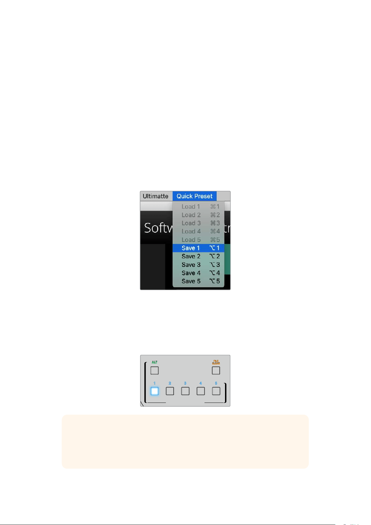
To save a quick preset using Ultimatte Software Control, click the ‘quick preset’ menu at the top
of the screen and choose a save option. To load a quick preset simply choose a load option
from the quick preset menu.
Use the preset menu to save and
loadquick presets
If your Ultimatte has numbered buttons on the control panel, you can also use these to recall
aquick preset.
On Smart Remote 4, hold down the ‘alt’ button on the left side of the panel and press a quick
save button. To load a quick preset, press the desired quick load button.
QUICK LOAD
QUICK SAVE
ALT
FILE
CLEAR
1 2 3 4 5
TIP For models with a built in control panel, quick presets are saved in Ultimatte’s
internal memory, so they will be available after you have power cycled the unit.
On Ultimatte 12 quick presets are saved in volatile memory so they are only available
until you power down your Ultimatte.
32Ultimatte Compositing Workflow
Quick Guide to Building a Composite
This is a basic introduction to performing a fast composite. You will notice while reading this
section that occasionally a feature will be specific to a particular Ultimatte model.
With all sources connected to the main unit, the first step is to make sure the backing color is
correctly set. The default backing color is green, but you can set it to red or blue, depending on
which color you are using on set.
If you are using a green screen, you don’t need to change the backing color as green is already
set by default. Clicking the ‘auto key’ button will perform an automatic composite and generate
a matte from your green screen.
TIP An automatic composite will also take place when power cycling your Ultimatte.
Setting the Foreground Backing Color
The backing color defines the color Ultimatte will use to generate the matte. Typically, the color
used for most screens for compositing is green, and this is why green is the default backing
color. However, there are occasions on set where red or blue may be a better choice based on
the color of the foreground objects. In this event, you will need to tell Ultimatte to use a different
backing color.
To set the backing color:
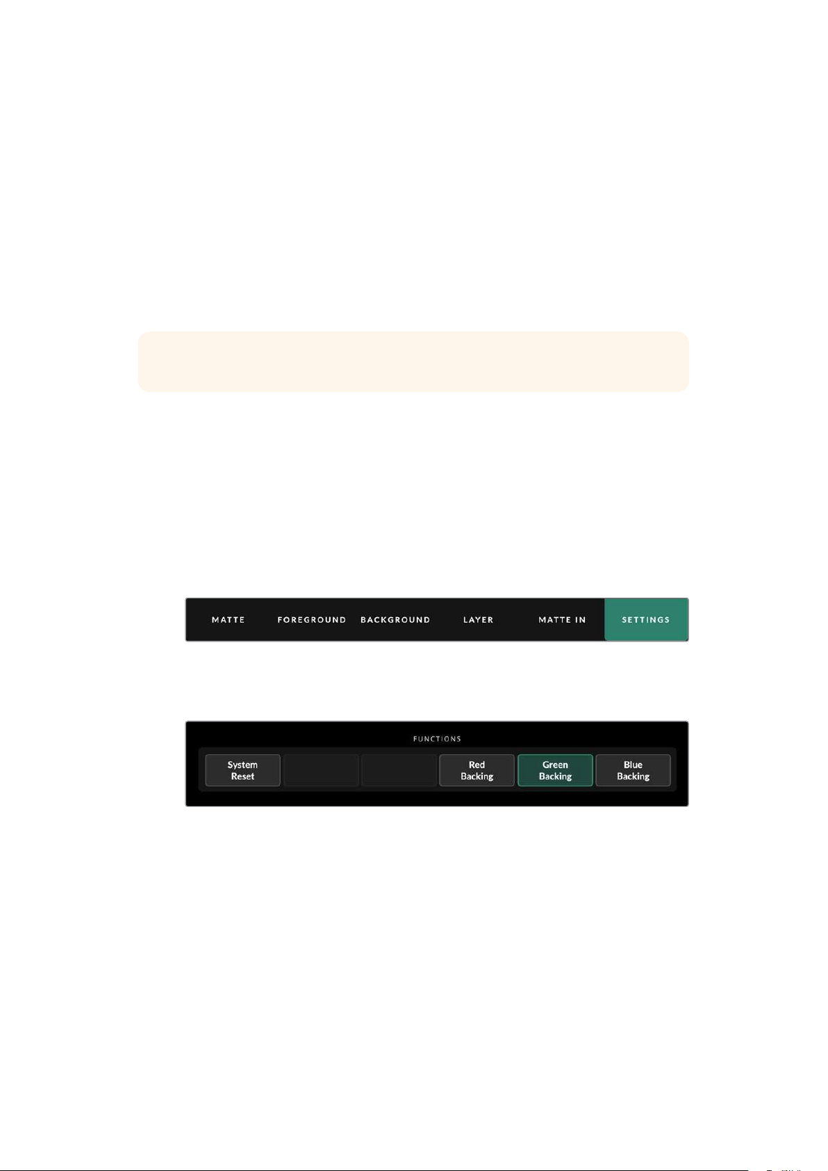
1 Click the ‘settings’ menu button to open the settings.
2 In the functions section, choose the red, green or blue backing buttons to select your
desired backing color. You will now see the backing color indicator in the status bar
change to the corresponding backing color.
Select a red, green or blue backing color from the functions area.
When the backing color is set, Ultimatte will perform an automatic composite and you will
see the results on the program output and Ultimatte’s front panel LCD. In the monitor output
area, select the program output and the image will appear on the monitor connected to the
monitor output.
33Quick Guide to Building a Composite
Setting Screen Correction
Screen correction can be helpful if there are strong variations in your backing screen, or the
lighting on the backing screen is uneven.
If your camera is static and you can remove all the foreground objects from the scene, you can
perform a screen correction. This shows Ultimatte what the screen looks like by itself, and then
once all elements are replaced, Ultimatte can then analyze what has changed in the foreground
and will generate an optimized matte. This can help tidy up any areas that are not behaving in
your matte.
To perform a screen correction:
1 Remove all the foreground elements in your scene so only the backing screen is visible.
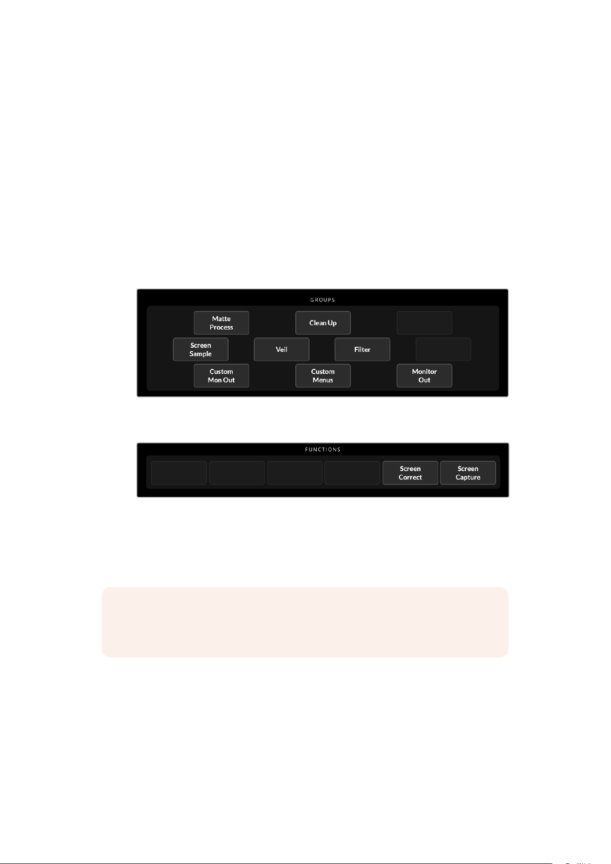
2 Select the ‘matte’ settings from the main menu buttons.
3 In the ‘groups’ section, select ‘matte process’.
4 In the functions area, click the ‘screen capture’ button. This stores a snapshot of the
green screen which Ultimatte uses to generate the screen correction.
5 Now replace all the foreground elements into your scene.
6 Click the ‘screen correct’ button.
Your Ultimatte will now analyse the foreground elements against the captured image and
determine the optimized matte.
NOTE When using the screen correction feature, it’s best to perform this function once
the camera is set and in place, because once the camera moves, screen correction will
no longer be effective and you will need to reapply the screen correction.
34Quick Guide to Building a Composite

Setting the Matte Density
If the matte needs some refinement, the first step is to adjust the matte density. This improves
the black areas of the matte so it is opaque. Any gray areas inside the black matte will cause
the background to show through the foreground in those areas.
To adjust the matte density:
1 Select the ‘matte’ menu button to open the matte settings.
2 Rotate the matte density control knob counterclockwise to decrease the matte density
until you start seeing the gray areas inside the black silhouette.
3 Now increase the matte density setting until the gray areas are no longer visible.
Be sure to stop adjusting as soon as the gray areas disappear. This is because the least
amount of adjustment will result in a more convincing composite. This is true for most
controls when refining your composite.
You should now see a near perfect composite on the program output. Now you can use the
additional matte settings, foreground, background, and layer settings to refine your composite.
Perfecting your Composite
After your initial key is generated, you may want to add further refinements to make your
composite even more convincing. Ultimatte’s advanced keyer has powerful tools to let
you enhance the composite, perfect the matte edges, color correct each layer, plus blend
backgrounds, foregrounds and layers together in very realistic ways. The tools are there for
youto use and we encourage you to investigate them and experiment so you can make the
most of your Ultimatte and achieve extremely realistic composites.
This section includes a brief outline of the prominent keying and compositing tools available
and the order in which they are often used. It’s worth mentioning that when adjusting some
controls, the smallest change can make best results and you may need to make minor
readjustments to some settings as you change others. Achieving the perfect key can be an
artform using finesse and dexterity.
1 Matte Adjustments - Further perfect the internal matte using the black gloss settings
for eliminating highlights that are keying in the darker areas of the foreground.
As you adjust the matte controls, you may notice a fine white haze over your composite.
This is the result of tiny changes to the environment, such as dust accumulating over
time, or scuff marks occurring as crew make changes on set. Use the ‘veil’ settings to
help remove the white haze, if the details are too prominent you may also need to clean
the set or repaint patches of the blue or green screen.
2 Clean Up Adjustments - Use the the clean up settings to remove imperfections in
your blue or green screen such as scuff marks, seams, unwanted shadows, electronic
noise and screen residue. Adjusting the clean up settings will electronically clean your
screen, we recommend using these controls sparingly as they can produce a hard
edged, cutout look to the final composited image if used broadly.
3 Flare - Ultimatte performs spill suppression automatically when keying the foreground.
Spill is when the green screen reflects onto the foreground elements, causing them
to shift their color in unpleasant ways. The flare controls can help refine the spill
suppression to further restore the foreground items’ original color.
4 Ambiance - Adjust the ambiance controls to add subtle color influences from the
background to the foreground layer, helping the foreground subject realistically blend
into its environment.
35Quick Guide to Building a Composite

5 Color Correction - Independently adjust brightness, color, contrast and saturation for
the different layers in your composite to increase their realistic blend. It’s best to make
color, brightness and saturation changes to the foreground image using Ultimatte’s
color correction settings rather than changing camera settings such as lens aperture.
This is because any change to the camera will also affect the key.
6 Additional Background and Layer Settings - Use the additional background and layer
settings to add elements such as lighting effects to your composition. For example, you
can create spotlight effects that shine down on you talent by using an image connected
to the layer input that is designed for a spotlight effect. You can then blend that image
into the foreground layer.
7 Additional Matte Input Settings - Add additional mattes to your composition,
forexample a garbage matte to remove unwanted foreground elements from your
composition, or a hold out matte to tell Ultimatte to ignore areas of the foreground you
don’t want to key. You can build a rough window using Ultimatte’s ‘window’ controls in
the matte input settings, or assign a custom matte image loaded in the media pool for
more precision.
There are many more advanced settings and tools you can use to improve the mattes,
strengthen the key, blend layers and generally build and finesse your final composite.
Details on how to use all the tools are provided throughout the rest of this manual so
you can explore your Ultimatte with confidence.
36Quick Guide to Building a Composite

Advanced Ultimatte Controls
This section contains information about all the settings in Ultimatte Software Control and how
touse them to operate your Ultimatte and refine and improve your composite.
Adjusting Matte Controls
Matte Density
As described in the previous section, the matte density setting lets you strengthen the general
opacity of the black areas of the matte, preventing areas of the background to show through
the foreground. This setting should always be adjusted first when perfecting your composite
after applying screen correction. The steps below include the additional steps of switching
between the monitor output and the program output so you can see both the matte and the
combined composite.
To adjust the matte density:
1 Select ‘matte’ in the main menu buttons.
2 In the ‘monitor out’ section, click on ‘combined matte’. You will see the foreground
subject appear as a black silhouette on a white field.
3 Using the control knob, decrease the matte density until you see details within
the black start to become gray. Now increase the setting until the gray areas
change to black.
4 Select the program output in the monitor out settings.
Any show through that was present prior to adjusting matte density should now be almost,
or completely, gone.
Black Gloss
Sometimes there may be dark areas of your foreground that have bright highlights which are
reflecting the backing color. These highlights can appear gray in your matte, which will cause
those areas in your foreground image to become transparent in your composite. The black
gloss setting helps to remove these areas from the matte.
Increase the black gloss setting while observing the combined matte output until these
reflective areas are no longer visible in the matte.
TIP If the matte is already opaque and there are no highlights showing, it’s worth
decreasing the black gloss level until you see the highlights, then increasing and
stopping as soon as they are no longer visible. This is because the lowest setting that
can be achieved will result in the cleanest, most convincing composite. This is true for
many of the matte controls.
Red, Green and Blue Density
As matte density and black gloss settings are increased, dark edges can form around
foreground objects. To compensate, the density of the color channels surrounding the edge
ofthe foreground objects can be adjusted.
For example, if your backing color is green, the colors available to adjust are red and blue.
If your backing color is red, the adjustable colors are green and blue. Adjusting these fine color
density controls can help clean up dark edges.
37Advanced Ultimatte Controls

Matte Reset
Click this button to restore all the matte controls that affect the foreground elements to their
default settings. The matte settings that affect the green screen area, for example clean up
andveil settings, will not be changed.
Clean Up Settings
Imperfections in your blue or green screen such as scuff marks, seams, unwanted shadows,
electronic noise, and screen residue are visually the same as fine details in the foreground.
As a result, these imperfections will also be visible in your final composited picture.
Adjusting the following controls will electronically clean your screen, but at the expenseof
thefinest detail on the edges of the foreground elements. We recommend using thesecontrols
sparingly as they can produce a hard edged, cutout look to the final composited image.
Todetermine the best settings, switch your monitor view between combined matte and
program out as your make adjustments.
To adjust the clean up settings:
1 While viewing combined matte, the screen area is represented as white. Adjust the
clean up controls so that the screen area is as close to white as possible without
eliminating important detail.
2 View program out to make sure that you haven’t eliminated too much of the fine detail.
The goal is to set these controls to the lowest possible value while ensuring the final picture
isnot missing subtle details such as fine wisps of hair, shadows, or reflections.
TIP Don’t get too focused on getting a perfect clean matte. Some imperfections
like slight scuff marks or electronic noise might actually look appropriate in the final
composited image, particularly if the background scene is a computer generated,
pristine image.
The clean up settings are interactive. Therefore, increasing one might allow you to decrease
one or more of the others. You’ll notice the greatest effect in the green screen area, but you
might also see a slight effect on the foreground elements.
Clean Up Level Increase or decrease to reduce or eliminate imperfections in the blue
orgreen screen.
Clean Up Dark Recover Use this control to recover shadows or edge detail on darker colored
elements that were reduced or eliminated by clean up level.
Clean Up Light Recover Increase this setting to recover edge detail on lighter colored elements
that were reduced or eliminated by clean up level.
Clean Up Strength
Use this control to add more strength to clean up light recover.
Clean Up Reset Click the clean up reset soft button to restore all clean up controls to
their default settings.
38Advanced Ultimatte Controls

Veil Settings
At this point while you are optimizing your matte, you may notice a fine white haze over your
final composited image. The haze can sometimes appear as a general haze, or localized in
patches corresponding to the screen area of the foreground source.
The white haze is known as ‘veil’ and you can minimize it by adjusting the veil settings. As you
make adjustments, switch your monitor view between fill output and program out to determine
the best veil settings.
Master Veil Increase or decrease to remove neutral colored veil over your program
or fill output.
Red, Green, and Blue Veil Adjust these controls respectively when you see a colored haze over
the program output.
Veiling can become more pronounced over the course of the day as your blue or green floor
gets dirtier or dustier. We recommend wearing slippers when not shooting if crew and talent
are walking on the blue or green screen. Repainting of the screen may become necessary to
remove permanent dirt and marks.
Shadow Level and Shadow Threshold
If you want your shadows in the foreground source to be more or less pronounced in your final
composite, increase or decrease the shadow level. The shadow threshold setting is used to
help separate unwanted dark screen areas from shadows.
Matte Process/Screen Correction
Depending on the conditions of your green screen, the backing color may not be consistent
which can reduce the effectiveness of the matte. If you are seeing noise or artifacts in your
matte that you can’t solve using the general matte settings, and you have access to an image
ofjust the green screen without foreground objects, then you can use screen correction to
improve the matte.
To set screen correction:
1 Remove all the foreground objects in your scene so only the green screen is visible.
2 Click on the ‘screen capture’ button so Ultimatte can store a snapshot of the
green screen.
3 Now replace all the foreground objects in your scene.
4 Click the ‘screen correct’ button.
You should now see a general improvement in your matte and final composite.
NOTE Screen correction only works with static camera shots. This feature is the best
choice for improving areas in the backing screen, and clean up controls can be used
as a last resort if areas still need improvement.
Matte Correct Horizontal Size
‘Matte correct H size’ analyzes all horizontal matte transitions, based on the size selected in
number of pixels, and applies the appropriate amount of correction to the horizontal transitions
which may need modification.
39Advanced Ultimatte Controls

Unlike regular matte sizing, which slightly reduces the overall size of the matte, the ‘matte
correct’ control selectively corrects only transitions which are not optimally corrected.
The ‘matte correct H size’ setting indicates the number of pixels within which the system will
analyze every transition. When the size is set to 0, no correction is applied.
Matte Correct Vertical Size
‘Matte correct V size’ analyzes all vertical matte transitions, based on the size selected in
number of lines, and applies the appropriate amount of correction to the vertical transitions
which need modification.
The ‘matte correct V size’ display indicates the number of lines within which the system will
analyze every transition. When the size is set to 0, no correction is applied.
Screen Sample
When Ultimatte creates the matte for the foreground, it automatically samples the backing color
in the foreground image to achieve the best matte. If varying shades remain visible in the matte,
you can set your Ultimatte to use single or dual sampling which can help achieve better results.
Single Sampling
Single sampling lets you manually select a single area of the foreground green screen with a
small box cursor. Ultimatte then assesses the color in that region and optimizes the sampling
ofthe backing color using that region.
To use single sampling:
1 Go to the screen sample settings in the ‘matte’ menu.
2 Click the wall cursor position button. Your view will change to the foreground input and
a small box cursor will appear on the screen.
3 Adjust the cursor horizontal and vertical position using the control knobs to move the
cursor to a spot on the wall near important detail. This can often be hair. Be sure to
avoid areas that contain detail that you want to retain.
4 Click the ‘sample wall’ button to save these screen values as your new reference.
Yourview will switch back to the monitor out setting you were last using.
Dual Sampling
Depending on the lighting conditions and your green screen, the floor area may appear at a
different luminance or shade of green compared to the walls which may affect the quality of
your matte when using the default auto sampling or manual single sampling.
To help Ultimatte achieve the best matte, you can select dual sampling and position two
separate cursors.
To use dual sampling:
1 Go to the screen sample settings in the ‘matte’ menu and click on ‘dual cursor’
toenable dual sampling mode.
2 Click the wall cursor position button. Your view will change to the foreground input and
two small box cursors will appear on the screen.
3 Adjust the horizontal and vertical position of the first cursor using the control knobs
tomove the cursor to a spot on the wall near important detail. This can often be hair.
Besure to avoid areas that contain detail that you want to retain.
40Advanced Ultimatte Controls

4 Click ‘sample wall’. Notice that ‘floor cursor position’ is now enabled and the floor
cursorposition is automatically available for you to adjust. Make your desired changes
to thesecond cursor position. For best results, select an area on the floor where
you see lighting glare or veiling, and avoid shadow areas that you want to retain in
the matte.
5 Click on ‘sample floor’. Your selection will save these screen values as your new
reference and the view will switch back to the monitor out setting you were last using.
Filter
The filter settings let you remove ringing artifacts that may appear in the transition edges,
plus provides noise reduction and noise generation settings to help blend foreground and
background elements together.
4:2:2 Correction level
In a Y,Cb,Cr 4:2:2 video image, objects with high contrast and sharp transitions can exhibit
a small edge artifact when used for green screen compositing. This is due to the reduced
bandwidth of the Cb and Cr color difference channels.
For example, a dark colored foreground object with sharp transitions shot against a bright
green screen will show an overshoot and an undershoot at the transitions. This is known as
ringing. These ringing artifacts are shades of black and white and will be treated as foreground
objects when processed, similar to gray strands of hair. When the green screen color is
removed and replaced by a dark background, a dark foreground object will show bright gray
edges at the transitions.
The 4:2:2 correction feature eliminates or reduces the ringing artifacts. No foreground object
detail is lost in this process.
4:2:2 correction is set to 100% by default. To make an adjustment, decrease the setting while
monitoring the program output until you notice the ringing artifact appear in the composite,
then gradually increase until it is no longer visible.
Noise Reduction/Generation
All video recorded using a video camera will contain a minor level of noise in the image.
When composited with pristine, noise free graphics generated by a computer, the difference
between sources can be noticeable.
To help blend elements, Ultimatte has noise reduction and noise generation settings that let
you clean noise from the foreground, and add noise to the clean areas of your composite.
For example, noise can be generated in the background or layer source, or areas of the
foreground that have been masked by a garbage matte.
There are two types of noise reduction. Median, and average.
To reduce noise:
1 Toggle between the average and median noise reduction types by clicking the
selection button on the left side of the functions section.
2 Now click the corresponding setting next to the selection button to set a noise
reduction level. Click multiple times to gradually increase the level. There are four
levels ofnoise reduction to choose from.
41Advanced Ultimatte Controls

To generate noise:
1 Click on the ‘noise cursor’ button in the functions section to enable the cursor on the
foreground source.
2 Using the cursor position controls, place the cursor on an area of the foreground that
displays the most prominent noise.
3 Click on the ‘noise select’ button.
4 Click on the ‘noise gen’ button to enable noise generation.
5 Increase or decrease the amount of noise generation using the ‘noise gen level’ control.
Matte Reset
The matte reset button restores all matte controls, including matte density, black gloss, color
density, and shadow settings to their default settings. These default settings could be factory
set or user set values. For more information on customizing your Ultimatte, refer to the ‘saving
and managing presets’ section.
NOTE Matte reset does not sample the backing for new reference color values. The
current values are used to recalculate spill suppression with any adjusted background
settings.
Matte Button
Click this button to disable or enable the matte generation and flare settings. The default
setting of this button is ‘enabled’.
Cursor Position Last
When this button is enabled, the cursor will return to the horizontal and vertical positions where
it was last used. This mode is helpful when studio cameras are mounted on robotics systems
and could be programmed to go to the same starting position, thus allowing the same exact
sampling locations to be used again. When you save a preset file, cursor location is also saved.
When disabled, the location of the cursor will always return to a default horizontal and vertical
position toward the top left hand corner of the image, regardless of the previously used
sampling location.
Auto Screen Sample
Auto screen sample is the default method of scanning, analyzing, and determining reference
backing color levels. Using this method, the matte signal is analyzed to detect the most
predominant highest level, which will correspond to the brightest and purest area of the
backing. Auto screen sample will also be performed during all of the functions listed below:
Main unit power up, system reset, backing color select, and auto key.
Adjusting Foreground Flare Controls
Your Ultimatte automatically analyzes the backing color reflecting onto foreground objects and
removes the effect of the bounce color in the final composite. This is called spill suppression.
The process of spill suppression can affect certain colors in the foreground. Thecolors affected
will vary depending on the backing color you are using. If you need to makecolor adjustments
to restore the original color of foreground elements, the results of spillsuppression can be
adjusted using the flare controls.
42Advanced Ultimatte Controls

Flare 1 Settings
Cool
Restores cooler colors, such as blue, green and cyan.
Skin Tone
Restores the color of natural skin tones that may have been changed by spill suppression.
Light Warm
When advanced flare is enabled, this setting recovers lighter, warmer colors,
such as red, yellow and orange. This setting interacts with the skin tones setting.
Black, Gray and White Balance
Use this setting to color correct the spill suppression in the tonal regions of the foreground,
such as the shadows, mid tones and highlights.
Flare Level
When advanced flare controls are enabled, this setting adjusts the overall amount
of spill suppression for certain foreground colors.
Holdout Matte Flare Button
When a holdout matte is used to stop the compositing process in portions of the foreground
scene, spill suppression on the foreground becomes slightly more complicated. In some
situations, removing spill suppression from the entire scene would result in a more convincing
look. In other situations, no spill suppression in the holdout matte area would be the
best choice.
When holdout matte flare is disabled, spill suppression is not performed in the holdout matte
region. When enabled, spill suppression is removed from the entire foreground scene.
Flare 2 Settings
Flare Correct Horizontal or Vertical Size
Flare correction analyzes the spill suppression in the transition areas and lets you make subtle
corrections. For example, neutralizing small color discrepancies, or luminance variations that
may be affecting fine edges in the transition area.
You can adjust the size of the area around the pixels of interest that Ultimatte will use to analyze
the spill suppression. This area is defined via pixel width and line height. When the size is set to
0, no flare correction is applied.
Dark Warm
When advanced flare is enabled, this control can help to restore brown colors, for green screen,
and purple colors, for blue screen. This control interacts with skin tones settings.
Flare Reset
Click this button to reset all flare controls to their default settings, depending on the backing
color selected.
Advanced Flare
Click this button to toggle the advanced flare controls on or off.
43Advanced Ultimatte Controls

Adjusting Foreground Ambiance Controls
To make a composite more convincing, it is important that the foreground subject fits
seamlessly into its new background environment. The ‘ambiance’ feature in Ultimatte analyzes
the colors of the background and foreground layers, and automatically adds subtle color
influences from the background into the foreground layer. This feature is enabled by default.
The ambiance controls also allow you to set the amount of influence that the background has
on the foreground layer, and finesse the color balance.
To make foreground ambiance changes:
1 Select ‘foreground’ in the main menu buttons.
2 In the ‘groups’ section, click on ‘ambiance 1’ or ‘ambiance 2’ to access these menus.
Ambiance reset
Click the ‘ambiance reset’ button to reset all ambiance controls to their default settings.
Ambiance
Use this button to disable or enable the ambiance feature. The default setting of this button is
‘enabled’.
Ambiance 1 Settings
The ambiance controls will add very subtle amounts of color from the background, simulating
reflected ambient light from the background source.
Ambiance Level Red, Green, Blue
Adjust these settings to increase or decrease effects of the red, green and blue components
ofthe background ambiance that will influence the foreground color levels.
Ambiance Level Master
This setting adjusts the overall level of the ambiance that will influence the foreground color
levels. When adjusting this control, the relative difference between the ambiance red, green,
and blue components will be maintained.
Ambiance Strength
This setting adjusts the strength of the ambiance that will influence the main area of the
foreground subject, compared to the transition areas from the foreground subject to the
background scene. At its maximum setting, the ambiance will have full influence on the main
area as well as the transition region, while at the minimum setting, the ambiance will have no
influence in the main area while having a stronger influence in the transition regions.
Direct Light Mix
This setting controls the proportion by which the foreground subject will be influenced by the
ambiance colors and user adjustable direct lighting. At the maximum setting, the foreground
subject is influenced entirely by the direct light controls, and at its minimum setting, the
foreground subject is influenced entirely by the ambiance colors.
Vertical Blur
This setting determines the number of averaged lines in the background used in ambiance
calculations. Depending on the background scene, reducing this control could introduce
streaking on the foreground layer.
Ambiance 2 Settings
The direct light controls will make more aggressive changes to the foreground image,
simulating light that is directly from a position in the front of the foreground subject.
44Advanced Ultimatte Controls

Direct Light Red, Green, Blue
Adjust these settings to increase or decrease the impact of red, green and blue components
ofthe direct light that will influence the foreground color levels.
Adjusting Brightness, Color, Contrast and Saturation
As you build your composite, you will likely want to make adjustments to the luminance,
color, contrast, and saturation levels for your sources which can help improve your composite.
For example, if the foreground, background and layer elements seem to differ in levels
compared to accompanying composited layers, you can perform an independent color
adjustment using the master controls for each source. All the same luminance, color balance,
contrast, and saturation settings are available for each source.
White Level Master
If a source seems too bright or too dark for the adjoining scene in the composite, adjust the
white level control to alter the brightness of the source rather than adjusting the original input
source level. Altering the level at the input source, for example the camera exposure, can
adversely affect the generation of the matte signal.
The default setting of the white level control is neutral at 100%. The range of the control is from
0% to 200%. When adjusting the white level master, the relative difference between the white
level red, green, and blue components will be maintained.
In normal white range mode the main unit will clip the output so the signal cannot exceed
standard limits. All Ultimatte models, except Ultimatte 12 also feature an extended white
range mode, in this mode all signals exceeding 100% will pass through unclipped. For more
information on output range, refer to the ‘settings’ section.
Black Level Master
The master black control adjusts the level of black in the source image without altering the
white level. Adjusting the black level can often produce a more convincing composite image,
if the black levels in the background scene differ from those in the foreground.
When adjusting the black level master, the relative difference between the black level red,
green, and blue components will be maintained. Ultimatte will clip black levels at zero so they
do not exceed standard broadcast limits.
Contrast Master
The contrast master control adjusts the overall contrast level of the source in the composite
without affecting the quality of the composite. For example, if the lighting contrast in the
foreground scene does not match that of the background scene, adjusting this control may
produce a more convincing composite image.
The contrast setting does not affect the strength of black and white levels, but only changes
thecontrast of the gamma, or mid level gain, in the source image.
When adjusting the contrast master, the relative difference between the contrast red, green,
and blue components will be maintained.
Saturation Master
The saturation master control adjusts the saturation level of the selected source colors without
affecting the generation of the matte signal. For example, if the saturation of the colors in the
background scene does not appear to match the saturation of the foreground colors, adjusting
this control may produce a more convincing composite.
45Advanced Ultimatte Controls

The saturation master control can completely remove all color from the source image and produce
a monochrome, or black and white, foreground composited with a color background image.
When adjusting the saturation master, the relative difference between the saturation red,
green, and blue components will be maintained.
Advanced Contrast Crossover Master
When the ‘advanced contrast’ button is enabled in the functions section, contrast adjustment
characteristics will acquire an “S” shape curve. The crossover point of the “S” shape can be
moved by the source ‘contrast crossover’ master control.
Fade Control
A fade control is available for the foreground, background and layer sources. This setting lets
you fade the foreground or layer source, if enabled, until it is no longer visible.
When the primary matte is disabled in the matte settings, you can use this feature to fade
between the foreground source and background source to line up props or set items in the
foreground with the background source.
When adjusting the fade or fade-mix control from 0% to 100%, the selected source will gradually
fade until no longer visible.
Color Correcting Black and White Levels
The ‘black/white level’ menu for each background, foreground and layer source lets you make
specific color corrections to the black level and white level. By adjusting the respective red,
green and blue color correction controls you can adjust each respective color level without
altering the overall gain.
TIP Any adjustments to color for the black and white level will only occur after the
matte signal generation and will not affect the source.
Adjusting Color Contrast and Saturation
The ‘contrast/saturation’ menu provides controls to adjust contrast for each color channel in the
selected source. Adjusting the contrast control for each channel will increase or decrease the
amount of contrast in the gamma, or mid level gain.
When the ‘advanced contrast’ button is enabled in the functions section, contrast adjustment
characteristics will acquire an ‘S’ shape curve. The crossover point of the ‘S’ shape can then
be moved by the source ‘contrast crossover’ control. This gives you greater control over how
contrast affects the gamma tonal region.
Color Reset
If at any time you want to restore the color correction back to its default state, simply click on
the color reset button in the functions section.
Source Freeze Button
If you are working with still graphics as your sources, this feature allows for greater flexibility. You
can take a still image from each source by clicking the respective ‘freeze’ button in the functions
section. This stores a still frame in temporary memory which you can use as the source.
The freeze feature can be helpful if you have limited playback equipment. For example, you can
save a still from a playback source graphic, then on the same playback deck, load a different
source and plug it into a different source input on your Ultimatte. This effectively doubles the
amount of sources you can use with your playback equipment.
46Advanced Ultimatte Controls

Additional Background Settings
Background Filter
In many situations, particularly with computer generated backgrounds, the graphics will appear
too sharp compared to the foreground subjects. Sometimes, this sharpness can cause aliasing
artifacts if the antialiasing filters are not set properly in the background rendering system.
Advancing the background filter control will gradually apply a horizontal low pass filter to the
background scene, minimizing aliasing artifacts.
Background Gradient
Enabling this button will replace the background video with an internally generated horizontal
gradient signal. This gradient signal can be used to better demonstrate the impact of
background color controls on the background image.
Test Signal
This setting lets you use a colored field as the background in the final composite.
Background Switch
If you have still sources assigned to both backgrounds one and two in the media pool, clicking
this button will switch between them.
Additional Layer Settings
Test Signal
This setting lets you use a colored field as the layer source in the final composite.
Lighting
Green screens are best optimized when lit flat in neutral light so there are minimal changes in
color and brightness. This can add interesting challenges if you want to create lighting effects
on the set as the lighting can spill onto the green backing affecting the strength of your key.
As a helpful and convincing alternative, you can use the lighting feature to simulate lighting
effects in your composite. For example, you may have pillars of atmospheric spotlights shining
down on your talent. By using an image connected to the layer input that is designed for a
spotlight effect, you can blend that image into the foreground layer. You can even create an
animated image that lets you create dynamic moving lighting effects that are veryrealistic.
The lighting feature is most realistic when the lighting image used for the foreground lighting
effect is also integrated into the background layer when designing your background image.
Thislets both the foreground and background share the effect which makes the overall
simulation more convincing.
To enable the lighting feature, select ‘layer’ from the main menu and then ‘lighting’ from the
‘groups’ menu. Now select ‘lighting’ from the ‘functions’ menu.
Lighting Control Knobs
Minimum Level
This control determines a mixture of the level of the ‘lighting’ input and an internal lighting
level setting. The range of the minimum level control is from 0% to 100%, with the default
setting at 25%.
At 0%, the lighting of the foreground subjects is entirely controlled by the ‘lighting’ input image.
At 100%, the lighting of the foreground subjects is entirely controlled by the lighting level R/G/B
and Master Controls settings.
47Advanced Ultimatte Controls

Color can be added to the Minimum Level by adjusting the Lighting Level Red/Green/Blue
andMaster controls.
Lighting Level – Red/Green/Blue
This controls the red/green/blue components of the ‘minimum lighting’ as it is applied to the
foreground subjects. The control range is from 0% to 200%, with the default setting at 100%.
Lighting Level – Master
The master control adjusts all three ‘minimum lighting’ level R/G/B controls simultaneously
whilemaintaining their individual setting relationships.
Layer Color Controls
When the ‘lighting’ feature is enabled, the ‘layer white level, Black Level, Contrast, and
Saturation controls will make corresponding adjustments to the Lighting Input image.
For a detailed description of these controls, see Adjusting Brightness, Color, Contrast
andSaturation section of the manual.
Layer Input
Enabling this function allows the layer elements to be added to the composite scene.
Layer Input Realistic/Linear/Additive
This function selects between three modes of combining the layer input elements with the
foreground objects and the background scene in the composite image.
Realistic
Most accurate method of combining colored transparent and semi transparent layer elements,
as well as opaque layer elements, with the foreground objects and the background scene.
NOTE When using a layer source graphic in realistic layer mode with semi transparent
objects, the image source background needs to be 100% white. The RGB elements in
the source layer should not be premultiplied by its matte. All feathering of transition
regions along edges of the matte should be within the boundaries of the layer
elements. For example, make sure feathered edges do not extend into the white
backing region of the source image.
Linear
Traditional method of combining opaque layer elements with the foreground objects and the
background scene in the composite image. This method will not produce accurate results with
transparent colored layer elements. This method should be selected if the layer elements are
not premultiplied.
Additive
Traditional method of combining opaque layer elements with the foreground objects and the
background scene in the composite image. This method will not produce accurate results
with transparent colored layer elements and should be selected if the layer elements are
premultiplied.
TIP Clicking the ‘auto key’ button will not change the layer input mode.
48Advanced Ultimatte Controls

Layer Switch
If you have sources assigned to both layers one and two in the media pool, clicking this button
will switch between them.
Matte Input Settings
Blackmagic Ultimatte can accept four different matte inputs, each assigned to a specific function.
These 4 matte inputs are:
Background matte
Garbage matte
Holdout matte
Layer matte
Background Matte
The background matte is associated with certain elements in the background scene that need
to be treated as their own layer. By converting these background elements into layer elements,
they can be moved in the layering order in front of the foreground objects. These background
elements that are converted to layer elements can only be opaque elements.
Garbage Matte
The garbage matte is associated with the boundaries of the foreground screen. It is used to
artificially extend the screen area, so that the background scene can be added in these areas.
The garbage matte should have a large soft transition area, from black to white, so that the
garbage matte blends better with the real screen area.
If foreground objects enter these soft transition areas of the garbage matte, these objects
will gradually become transparent and mixed with the background scene until they are fully
faded out.
In an alternate process, Blackmagic Ultimatte can gradually apply the garbage matte clean up
function in the soft transition areas so that the foreground objects can still enter these transition
areas without becoming transparent.
Holdout Matte
The holdout matte is associated with elements of foreground objects which have similar colors
as the screen color. The holdout matte can be used to prevent these portions of foreground
object areas with similar color as the screen from becoming partially or fully transparent.
Additionally, the holdout matte can be used to retain or remove the foreground object colors
that are similar to the screen color.
Layer Matte
The layer matte is associated with the ‘layer in’ elements. The layer matte is used to determine
the opacity of the corresponding ‘layer in’ source. The layer elements associated with the layer
matte could be opaque or can have varying levels of transparency with different colors.
Window
The window setting lets you create internally generated mattes with rectangular proportions.
The resulting window can be used as a rough garbage matte, allowing you to exclude certain
areas from the foreground image. Enable window by clicking the ‘window’ button, then set the
input source you want to apply the window to by clicking the respective matte button in the
functions section of Ultimatte Software Control.
49Advanced Ultimatte Controls

Adjust the positioning of the window edges using the following controls:
Window Position Top, Bottom, Left and Right
These knobs adjust the position of the top, bottom, left and right edges of the window.
The default position is beyond the edge of the frame. As it is dialed in, the edge moves
into the frame and goes all the way to the opposite position of the frame.
Window Softness Top, Bottom, Left and Right
Sometimes you may want to reduce the harshness of a window edge in the garbage
matte. To do this, increase the softness control for the window edge you want to adjust.
The default position is beyond the edge of the frame. As it is dialed in, the edge moves
into the frame and goes all the way to the opposite position of the frame.
Window Skew
The window skew function allows you to create an internally generated window matte with
non-rectangular proportions. Using the skew controls, you can tilt and rotate each edge of
the window independently to create a rough garbage matte, to exclude certain areas from the
foreground image.
Enable window skew by clicking the ‘window skew’ button, then adjust the skew for each edge
using the control knobs.
Adjust the skew of the window edges using the following controls:
Window Skew Top, Bottom, Left, Right
These knobs adjust the skew of the top, bottom, left and right edges of the window.
Window Skew Offset Top, Bottom, Left, Right
As it is dialed in, the skewed window edge moves into the frame and goes all the way
to the opposite position of the frame.
Transition Rate
This control sets the rate, in number of frames, by which the objects in the background scene,
defined by the background matte and the layer input elements, will move in front of or behind
each other in the composited image.
When the transition rate is set to 1, the changes in the layering order will be an abrupt cut. When
the rate is increased, the transition will be a smooth mix dissolve. The maximum transition rate
is 120 frames.
The transitions are initiated by selecting one of up to six different layering orders defined in the
functions section.
Setting the Layer Order
In the functions section you will see buttons that indicate the layer order. These buttons
determine the order of how the foreground source, background source, and the layer source
elements are arranged in your composite. The buttons available will depend on which mattes
you have enabled.
The first name in a button is the top element in the layering order, and the last name is bottom
element. For example, you’ll notice that the background is always the bottom element in
the scene.
When both background matte elements and layer source elements are used, the 6 possible
combinations are:
50Advanced Ultimatte Controls

FG / LY IN / BG LY / BG
Foreground source as the top layer, followed by the layer source elements, followed by
the background layer elements separated from the background source, then followed
by the background source.
LY IN / FG / BG LY / BG
The layer source is the top layer, followed by the foreground source, followed by
the background layer separated from the background source, then followed by the
background source.
LY IN / BG LY / FG / BG
The layer source is the top layer, followed by the background layer elements separated
from the background source, followed by the foreground objects, then followed by the
background source.
BG LY / LY IN / FG / BG
The background layer elements separated from the background source are the top
layer, followed by the layer source, followed by the foreground source, then followed by
the background source.
BG LY / FG / LY IN / BG
In this combination, the background layer elements separated from the background
source are the top layer, followed by the foreground source, followed by the layer
source, then followed by the background source.
FG / BG LY / LY IN / BG
In this combination, the foreground source is the top layer, followed by the background
layer elements separated from the background source, followed by the layer source,
then followed by the background source.
When only the background layer is used via a background matte, the 2 possible
combinations are:
FG / BG LY / BG
The foreground source is the top layer, followed by the background layer elements
separated from the background source, then followed by the background source.
BG LY / FG / BG
In this combination, the background layer elements separated from the background
source are in the top layer, followed by the foreground source, then followed by the
background source.
When only the layer input is used, the 2 possible combinations are:
FG / LY IN / BG
The foreground source is the top layer, followed by the layer source, then followed
bythe background source.
LY IN / FG / BG
In this combination, the layer source is in the top layer, followed by the foreground
source, then followed by the background source.
51Advanced Ultimatte Controls

Settings
The settings section in Ultimatte Software Control lets you change video settings, access the
media pool and make adjustments to the inputs and outputs.
System
The system menu lets you select your Ultimatte’s video format, change color space settings
and set the 3G-SDI output level.
Video Format
Select your video format from the menu, or set it to ‘auto detect’.
3G SDI Outputs
Ultimatte will detect a level A or level B 3G-SDI input automatically. The output is set to level B
by default, but you can change it to level A if needed.
To change the 3G-SDI output to level A or B:
1 Go to the ‘settings’ menu in Ultimatte Software Control.
2 Click on the ‘system’ button. A window will appear with checkboxes for level A and
Level B 3G-SDI.
3 Select the desired level checkbox, then click ‘apply’ to confirm the setting. Click ‘close’
toexit the window.
HD/UHD Color Space
All Ultimatte models, except Ultimatte 12 HD Mini support Rec. 2020 color gamut for both HD
and Ultra HD. When Rec. 2020 is selected, all input signals must comply with Rec. 2020, and all
output signals will conform accordingly. When your Ultimatte detects standard definition, itwill
automatically set the color gamut to Rec. 601 so you don’t have to change the setting when
using SD video.
To set the color space:
1 Go to the ‘settings’ menu in Ultimatte Software Control.
2 Click on the ‘system’ button. A window will appear with checkboxes for Rec. 709
and Rec. 2020
3 Choose the color space you want to use, then click ‘apply’ to confirm the setting.
Click‘close’ to exit the window.
Media
The media button gives you access to the media setup settings. Click the media setup button
to open the media pool window, you can then upload still images to the media pool and assign
images as sources using the ‘assignment’ tab. For more information, refer to the ‘using the
media pool’ section.
Inputs
The inputs menu gives you access to the timing controls if you need to delay the foreground
input to be synced with the background signal and to make subtle timing corrections to a
source input signal.
52Settings

Frame Delay Foreground Input
This control will set the number of frame delays to the foreground input. The control range is
from 0 frames to 14 Frames.
In a 4:2:2 signal, the relative timing samples between luma and the chroma, or Y and UV
respectively, are well defined. However, some cameras might have some amount of relative
luma or chroma timing error. When viewed on a monitor as red, green or blue only, the image
will look like an ‘embossed’ picture. This timing error will cause unnatural transitions and off
color edges.
If there are no adjustments in the camera to correct the timing, Ultimatte’s inputs menu gives
you access to the timing controls if you need to make subtle timing corrections to a source
input signal.
Foreground Input U Position
This control will only adjust the U timing relative to Y in sub pixel values.
The maximum range of adjustment is +/- 2 pixels.
Foreground Input V Position
This control will only adjust the V timing relative to Y in sub pixel values.
The maximum range of adjustment is +/- 2 pixels.
Foreground Input UV Position
This control will adjust both the U and V timing relative to Y in sub pixel values. Therelative
difference between U and V will be maintained. The maximum range ofadjustment is
+/- 2 pixels.
Outputs
The output configuration settings let you customize the appearance of the outputs and route
certain outputs to help your workflow. For example, setting the talent output to mirror, or routing
the monitor output to the program output. Some of the output settings are dependant on the
Ultimatte model you are using.
You can also enable the powerful cascade monitoring feature which lets you view the program
output for multiple Ultimatte units via one single unit as soon as you select a unit to control in
Ultimatte Software Control.
Talent Highlight Level
This control adjusts the amount of highlight applied to the image viewed on the talent output
areas where background mattes, garbage mattes, holdout mattes and layer mattes are used.
Matte Out Level
Internal to the unit, the matte signal is set so that fully opaque foreground objects are at 0%
black and peak backing areas are at 100% white. The matte out level of 100% white is set at 940
for a 10-bit output. Similarly, 0% black is set at 64.
NOTE The ‘matte out invert’ function will invert the polarity of the matte out.
The matte out level adjusts the level of the matte out from the white end. This control can lower
the matte out level to 0% or push it into the legal ceiling.
53Settings

Monitor to Program
In most situations, it is advantageous and safe not to be able to switch the program output to
other views. However, there are times when the program out view needs tobe changed from
the composited image to another view. For example, the matte view. For these few instances,
itis possible to route the monitor output to the program output.
When ‘monitor to program’ is enabled, the program output will show the same view selections
made in the monitor output. Disabling monitor to program will return the program output to its
previous setting.
Fill Linear Mix Correct
If the system you are using to combine the matte and fill outputs does not have an ‘additive
mix’ capability, for example linear mix only, the composite image can have dark edges due to a
second processing of the processed foreground image. Enabling the setting marked ‘Fill Lin Mix
Cor’ will minimize potential artifacts caused by the second processing of the foreground image.
Use this setting when you are sending the matte and fill to an external device for final mixing,
for example a broadcast switcher.
Talent Mirror
Selecting this option will horizontally mirror the program image viewed on the talent output.
The talent monitor output is used for the foreground subjects on the set to see themselves
inserted in the new background scene. By providing the capability to horizontally mirror the
viewed image, the talent can have a more natural feedback whenseeing themselves on
the monitor.
Monitor to Talent
When ‘monitor to talent’ is enabled, the talent output will show the same view selections made
in the monitor output. Disabling the monitor to talent will return the talent output view to its
previous setting.
Output Range
With normal video signal levels, the maximum white level is specified at 100%, and any signal
levels above that level will usually be limited to 100%. In extended video levels, the maximum
white level is allowed to exceed 100%.
Ultimatte 12 always uses ‘normal white range’ mode. All other Ultimatte models use ‘normal
white range’ mode by default, or you can switch on ‘output full range’ to enable ‘extended white
range’ mode. This applies to the foreground, background and layer inputs and outputs. Matte
inputs and matte output maintain normal white range for both modes.
In normal white range mode, any input signal levels exceeding 100% will be clipped to that level
at the output. Additionally, color adjustments applied to the video signals, for example white
levels, that can take signal levels above 100% will be limited to that level at the outputs.
In extended white range mode, all input signal levels exceeding 100% will pass through the
system unclipped. Also, color adjustments applied to the video signals will allow output levels
to exceed 100%.
Matte Out Invert
Enabling this function will invert the polarity of the matte out signal.
Output Oset
The output offset control allows you to adjust the output reference timing relative to the
foreground or analog reference input to match the timing of various devices in large systems.
54Settings

Monitor Cascade
The monitor cascade feature can be accessed from the ‘information’ symbol on the right side
of the menu name section of Ultimatte Software Control. You can find the setting under the
‘configuration’ tab.
When the monitor cascade feature is disabled, the monitor output will be the view selected
by the monitor out options. For a single Blackmagic Ultimatte unit, the monitor output can be
connected to a video monitor directly. Typically, if there are multiple Blackmagic Ultimatte
units, the monitor output for each unit can be connected to a routing switcher for monitoring
multiple outputs.
Alternately, with multiple Blackmagic Ultimatte units, they can be daisy chained via their monitor
inputs and outputs, with the last unit plugged into a monitor. Then when you select a unit in
Ultimatte Software Control, the monitor output for that unit can be viewed on that monitor. This
is an efficient and powerful way to monitor the output from up to eight Ultimatte units via one
single unit.
To connect four units for cascade monitoring:
1 Connect each Ultimatte unit to an analog reference source or to foreground sources
that are locked together.
2 Connect the first unit’s monitor output to the monitor input of the second unit.
3 Connect the monitor output of the second unit to the monitor input of the third unit.
4 Connect the monitor output of the third unit to the monitor input of the fourth unit.
5 Connect the monitor output of the fourth unit to a monitor.
When the monitor cascade feature is enabled, the viewed image on the video monitor
will be of the unit that is selected in Ultimatte Software Control as the currently active
unit. When the unit selection is changed, the image viewed on the video monitor will
change to the monitor out of the selected unit.
On Air Settings
The on air settings let you enable on air indicators for the status bar, LCD display and set your
Ultimatte to lock its controls when the unit is on air.
NOTE These controls only work when tally signals are connected to the GPIO input
and properly configured from the external tally generator on all models except
Ultimatte 12 HD Mini. Ultimatte 12 HD Mini can receive tally signals via the HDMI PGM
output or SDI Return input.
On Air
When this button is enabled, the unit indicator in the Ultimatte Software Control status bar
willilluminate red when on air. The unit identification number above its selection button will
alsoilluminate red.
On Air Lock
When enabled, the on air lock feature will lock all the controls for the unit currently on air.
Thishelps to prevent any accidental changes to a unit that is live on air.
55Settings

GPI and Tally Settings
These settings enable or disable tally signals when connected to an external GPI and tally
interface. Tally lets you monitor on air indicators so you know when an Ultimatte unit is currently
on air. GPI inputs and outputs let you trigger Ultimatte preset files as GPI events, similar in
nature to loading and running macros.
GPIO MENU
The GPI inputs allow external devices to trigger saved setup files in each input in a pre-
determined order. The maximum number of events is defined by the number of GPI inputs,
therefore the number of events you can use is five.
It is also possible for the main unit to trigger events in other devices using the GPI output.
Thistriggering can be done manually, or upon loading a file if the GPI output was saved as
partof that file.
GPI OUT Delay Frames
This control knob sets the delay, in number of frames, between triggering the event and the
execution of the GPI output switch closure. The maximum delay is 120 Frames.
GPI Functions Buttons
You can use the GPI functions buttons to add a GPI output to the current workspace settings,
toggle between low and high GPI output states and provide a programmable state output.
GPI Output Save
In order to initiate a GPI output upon loading a file, the appropriate instructions must besaved
as part of that file. When ‘GPI out save’ is selected, the instructions to trigger a GPI output will
become part of the current workspace settings. When the current workspace settings are
saved as a setup file, the instructions to trigger the GPI output are saved with this file.
When the saved file, which includes the triggering instructions, is loaded into the current
workspace, the triggering instructions will initiate the proper GPI output sequence.
GPI Out Low/High
Clicking this button toggles the GPI output state between low and high.
GPI Out
This provides a programmable state output, whose width and level are dependent on the
GPIout low/high setting and GPI out delay adjustment.
GPI Setup Menu
From the GPI setup menu, you can choose GPI files from the list of previously saved setup files
and load them into each GPI input. You can step through each file to verify that the selected
files were the correct ones, and that the sequence by which these files were listed was correct.
If needed, you can edit each GPI list by removing, adding, or inserting any number of files.
GPI 1 to 5
These windows allows the user to set up the files in the order by which they will be loaded
when triggered by the signal connected to each respective GPI input.
Add
With each click, this button will add the highlighted file in the files list to the selected GPI
events list.
Remove
Click on this button to remove a highlighted file from the selected GPI events list.
56Settings

Remove All
This button will remove all the files from the selected GPI events list.
Step
Click this button to move down through the highlighted file selection and automatically load the
selected file into the current work space. Any file on the GPI events list can be highlighted and
loaded in the current work space by touching the corresponding file name.
Reset
Clicking this button will select the top file from the GPI files list without loading the first file.
Thefirst file will be loaded when the first GPI pulse is detected.
GPI Input Enable
This checkbox enables or disables individual GPI inputs separately based on the setting of the
GPI input select control.
GPI High Enable
Enables the software to detect either low to high or high to low transitions of the GPI inputs.
The GPI inputs are triggered by the logic level of the input signal, not by the transition edges.
IfGPI high enable is checked, the selected input will be triggered by a high logic state. If GPI
high is not checked, the selected input will be triggered by a low logic state.
GPI IN Delay
This is a delay between detecting a GPI input and that of actual execution of the GPI list.
TheGPI input delay can be set at different values for each input. The maximum delay is
120 Frames.
Close
Selecting this button will close the window and exit the GPI setup menu.
Setting Up a GPI Event List
To set up an event list, preset files must be previously created and saved. Refer to the ‘saving
and managing presets’ section for more information.
1 Click on the ‘settings’ menu button and select ‘GPIO’ in the groups section. Click the
‘GPIO setup’ button and the GPIO setup window will be displayed.
2 From the tabs, select a GPI number from 1 to 5 to be used. If the selected GPI number
was used before, the event list will show the previously selected files. The existing
event list can be edited by removing, adding or inserting files. Alternately, select
‘remove all’ to remove all the files from the event list.
3 Select the file to be added to the event list. When selected, the file will be highlighted.
4 Click on the ‘add’ button to add the file to the event list.
5 To add more files to the event list, repeat steps 3 and 4.
When the event list is complete, click ‘reset’ to move to the beginning of the event list. Adjust
GPI input delay if necessary. This is the delay, in frames, when loading the files from the time
the GPI pulse is received.
1 For high GPI input logic state, select the ‘GPI high enable’ checkbox. Leave deselected
if using a low logic state.
2 Enable GPI by selecting the GPI input enable checkbox.
3 Repeat these steps for each GPI input.
57Settings
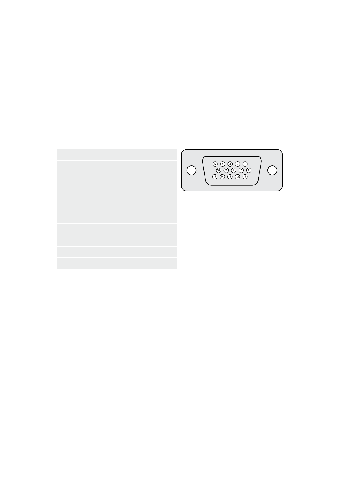
To edit an existing events list:
1 Select the GPI event number to be edited.
2 Select a file to be deleted by choosing the file name and clicking the ‘remove’ button.
3 To insert a new file into the event list, select the file below the area in the list you want
to insert the new file. Now click the ‘insert’ button.
4 When editing is completed, click ‘reset’ to select the beginning file of the event list,
thenclick ‘close’ to exit the GPI setup window.
GPIO Pinout
The female GPIO connector on your Ultimatte’s rear panel is a DE-15 connector. If you want to
build a cable for your own custom GPI and tally solution, a pinout chart is provided below.
GPIO PIN CONFIGURATION
Signal Input Pins
Return Output Pins
andGround Pin
1 = GPI 0 6 = GPI 0 R
2 = GPI 1 7 = GPI 1 R
3 = GPI 2 8 = GPI 2 R
4 = GPI 3 9 = GPI 3 R
5 = GPI 4 10 = GPI 4 R
11 = Tally 12 = Tally R
13 = GPO 14 = GPO R
15 = GND
Monitor Out Settings
This selection will show all the viewing options available. The button name will be changed to
‘return’ which you can click on to go back to the previous menu. Monitor out settings configure
the output from the ‘monitor out’ connector.
Monitor Highlight Level Control
This control adjusts the amount of highlight applied to the image viewed on the monitor output in
the areas where background mattes, garbage mattes, holdout mattes and layer mattes are used.
Monitor Setting Buttons
The monitor setting buttons allow you to change the matte view and select individual color
channels to view independently.
Matte View Range
The quality of images viewed on video monitors depends on the monitor’s brightness and
contrast setup. In many situations, the detail information in the very dark and very bright
portions of an image is sacrificed so that the rest of the image can have a more pleasant look.
The levels in a matte image cover the whole brightness gamut and most of the matte controls
are adjusted while observing matte levels near the darkest or the brightest end.
For this reason, it is difficult to adjust the matte accurately while looking at a monitor and
observing the darkest and brightest portions of the images.
58Settings

Enabling the ‘matte view range’ function will raise the black level and reduce the white level of
the matte signal so that detail information in the blackest and whitest sections of the matte can
be viewed accurately on a monitor.
Reducing the range of the matte on the monitor output has no effect on any internal processing
or the signal levels of the matte out.
Matte View Invert
When combined matte view or internal matte view is selected as the monitor output, the matte
polarity can be reversed by the matte view invert function.
Monitor Out RGB
When selected, the monitor output will show all three color channels of the image viewed.
Monitor Out Red, Green and Blue
All three color channels can also be viewed independently. When the respective color channel
button is enabled, the monitor output will only show that particular color channel as a black and
white image. This can be helpful to spot noise, which is predominantly in the blue channel.
Custom Monitor Output Menu
The monitor out section of Ultimatte Software Control provides six soft buttons which switch the
view on Ultimatte’s monitor output. These six soft buttons can be customized using the ‘custom
monitor out’ settings.
The first two soft buttons in the functions area of the interface are labeled ‘standard’ and
‘inputs’. These let you set the labels of the buttons to the standard default Ultimatte monitor
output buttons, or you can match the buttons to the respective inputs. When inputs is selected,
you can easily monitor every source by clicking the respective input button.
Below is the configuration for each setting:
Standard
Inputs
PGM Out
BG In
FG In
Layer In
BG In
BG Matte In
Combined Matte
Garbage Matte In
Internal Matte
Holdout Matte In
Fill Out
Layer Matte In
You can also create up to four custom monitor out buttons. These can be set to show your
favorite views in the order of your choosing.
To configure a custom monitor output button:
1 In the ‘matte’ settings, click the ‘custom monitor out’ button in the groups Section.
2 Click on the ‘configure’ button in the groups section.
3 In the dialog box, select any of the tabs labeled MONITOR OUT 1, 2, 3, and 4.
4 From the menus, choose which of the following potential monitor outputs you would
like to assign to each of the buttons. You do not necessarily need to assign a function
to each button. If ‘none’ is chosen, that button will appear blank.
59Settings
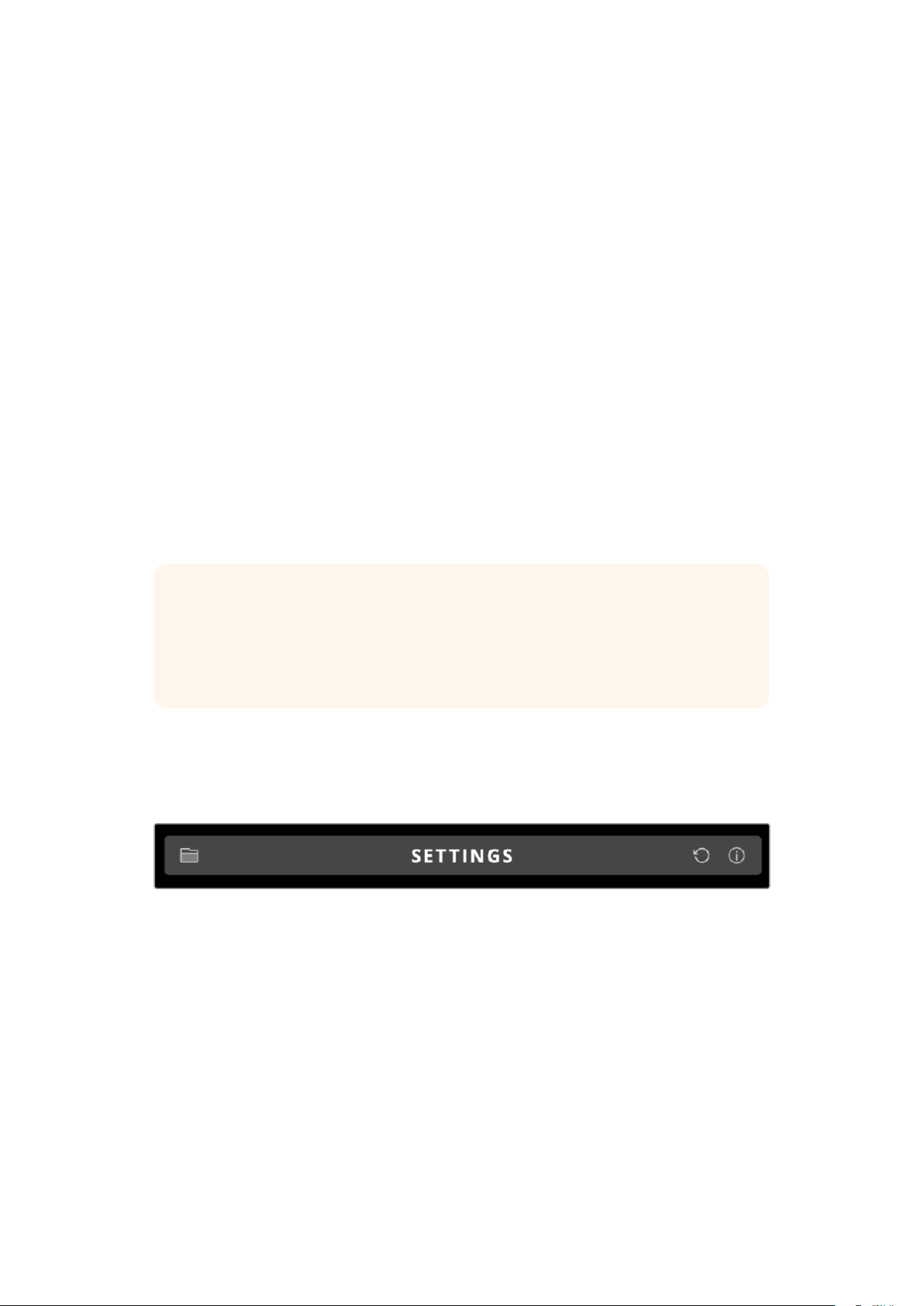
– Program
– FG In
– BG In
– Combined matte
– Internal matte
– Fill Out
– Layer In
– Background matte in
– Garbage Matte In
– Holdout Matte In
– Layer matte in
– Processed L M. Layer matte with adjustments applied.
– Processed H M. Holdout matte with adjustments applied.
– Processed G M. Garbage matte with adjustments applied.
– Processed B M. Background matte with adjustments applied.
– Screen correction capture. Image captured and used for
screen correction function.
5 Click on ‘apply’ to save your choices.
To load a custom monitor configuration, select ‘custom monitor out’ in the groups
section, and then choose one of the custom monitor buttons.
Presets
Presets make it easy to quickly save and recall setup and composite settings for your Ultimatte.
Presets are interchangeable between all Ultimatte models with a built in LCD.
TIP When you save a preset your Ultimatte will also save any image and video
assignments that you have set in the media pool. For example, you can save presets
1 and 2 with different still image backgrounds and save preset 3 with a live video
background, then cut between the backgrounds using the preset buttons on your
Ultimatte’s front panel.
Saving and Managing Presets
Clicking the folder symbol in the files and information section of Ultimatte Software Control
opens the presets window.
The presets window gives you access to all the preset management functions on your
Blackmagic Ultimatte including saving, loading, exporting and assigning presets to ‘quick
preset’ shortcuts.
60Presets

The preset window in Ultimatte Software Control
To save a preset:
1 Once you have a foreground source connected to your Ultimatte and have adjusted
your composite parameters, click on the file icon to open the presets window.
2 In the ‘preset name’ field, type in a name for your preset and click the ‘save’ button.
3 The saved preset will appear in the presets list.
To delete a preset:
1 Select the preset you want to delete from the list of saved presets.
2 Click on the ‘delete’ button and confirm your choice.
To load a preset:
1 Select the preset you want to load in the saved presets list.
2 Click the ‘load’ button. In the saved preset list, ‘active file’ will now appear next to the
loaded preset.
Renaming a preset:
1 Select the preset you want to rename from the saved presets list. The current preset
name will appear in the ‘preset name’ field.
2 In the ‘preset name’ field, type in a new name for the preset. Click the ‘rename’ button.
Assigning presets
You can assign up to five presets to ‘quick preset’ shortcuts. This lets you access presets
quickly using the ‘quick preset’ menu in Ultimatte Software Control or by using the numbered
buttons on units with built in LCDs. You can also recall presets using the ‘quick load’ buttons on
Smart Remote 4.
To assign a preset to a quick preset shortcut:
1 Select a preset from the preset list.
2 Use the ‘assign to’ menu to assign the preset to a quick preset shortcut.
61Presets

Use the ‘assign to’ menu to assign presets to quick preset shortcuts.
Importing and Exporting Presets
On all models except Ultimatte 12, you can import and export presets to and from your
Ultimatte. This can save time if you are setting up multiple Ultimattes and want to make sure
thatthe composite parameters are the same across all the units.
To export a preset:
1 Click on the folder icon in the files and information section of Ultimatte Software
Control to open the presets window.
2 Select the preset you want to export from the saved preset list.
3 Click the ‘export’ button and choose a destination to saved presets list. Click ‘save’.
To import a preset:
1 Open the presets window.
2 Click on ‘import’.
3 In the dialogue box, navigate to the preset you want to import. Click ‘open’.
4 The imported preset will appear in the saved presets list.
62Presets

Archives
An archive is a backup of your Ultimatte that includes its current state, all settings, presets and
the contents of the media pool. Creating an archive of your Ultimatte is useful if you regularly
switch between different productions or if you are setting up additional Ultimatte units.
Archives are interchangable between Ultimatte models.
Creating an Archive
To create an archive click the folder symbol in the files and information section of Ultimatte
Software Control, this will open the preset and archive window.
1 At the bottom of the preset and archive window click the ‘archive all’ button.
2 In the dialogue box choose a destination for your archive and type in a name.
Click ‘save’.
Your Ultimatte will now start creating the archive and display a progress bar. Once complete,
the archive will appear as a .zip file on your computer.
63Archives
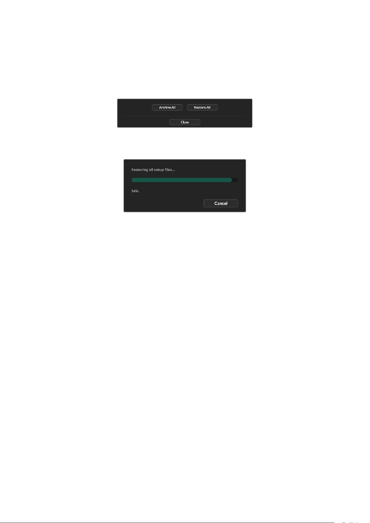
Restoring an Archive
To restore an archive, click the folder symbol in the files and information section of Ultimatte
Software Control.
1 At the bottom of the preset and archive window click the ‘restore all’ button.
2 In the dialogue box navigate to the archive file that you want to restore. Click ‘open’.
3 Your Ultimatte will now start restoring the archive and a progress bar will be displayed.
When the restore is complete the settings, presets, quick presets, GPI settings and media pool
stills will be available on your Ultimatte.
64Archives

Customizing the Menus
You can change the assignment of the Ultimatte Software Control and Smart Remote 4 control
knobs and buttons in the ‘settings/custom menus’ settings.
To set a custom menu:
1 Go to the ‘settings’ menu.
2 Click on the ‘custom menus’ button.
3 Choose one of the four custom menu presets you want to set.
4 A new ‘configure’ button will appear just above the custom menu preset buttons.
Click this ‘configure’ button. The custom menu setup dialog box will appear.
The control knob functions are in the left side column, and you can set a function from that
column to each of the eight slots on the right side column. The eight slots correspond to the
control knobs as follows:
Item 1 = Top left control.
Item 2 = Left second control down.
Item 3 = Left third control down.
Item 4 = Left bottom control.
Item 5 = Top right control.
Item 6 = Right second control down.
Item 7 = Right third control down.
Item 8 = Right bottom control.
To assign functions to each control knob:
1 From the ‘knobs’ list, scroll up and down the list of functions and select a function
from the list.
2 Click on the right arrow icon in the middle column that corresponds to the desired slot.
You will see the name of the selected control appear in the blank slot.
TIP If you change your mind and want to assign a different function to that
slot, simply click the left arrow to remove that function form the slot and assign
a different function.
3 Repeat steps 1 and 2 as you progress through all the slots to assign your custom
functions to each control knob.
4 Click on the ‘buttons’ tab to assign the buttons. Follow the same procedure as shown
above to set the buttons controls.
5 When you are happy with your selections, click ‘apply’.
You will now see all your customized controls on the interface.
If you are moving through other menus and want to return to your custom menus, you can
enable them by clicking ‘custom menus’ in the groups section, then press the desired custom
menu button. You will now see all the controls and functions buttons change back to your
custom selection.
65Customizing the Menus
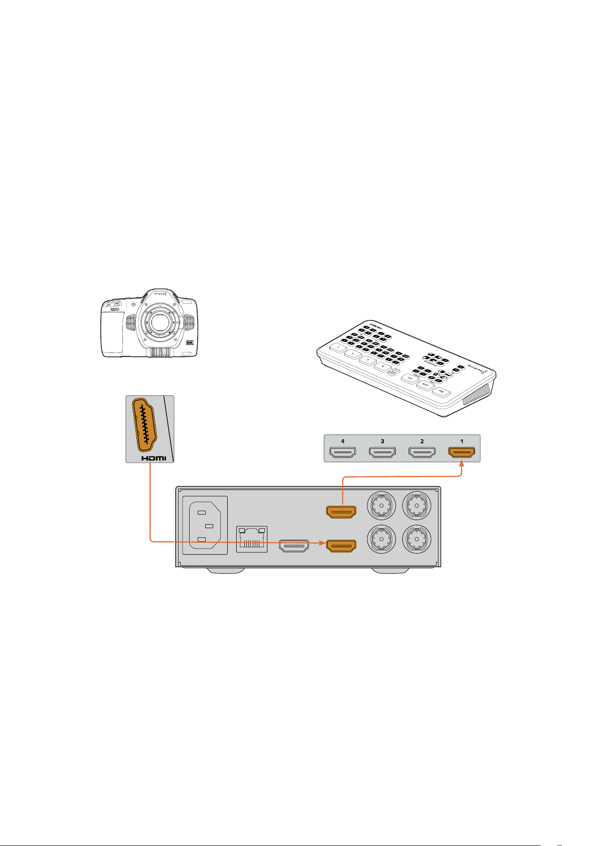
Camera Control via Ultimatte 12 HD Mini
Connecting Ultimatte 12 HD Mini to a Blackmagic Pocket Cinema Camera and an ATEM switcher
lets you maintain camera control and tally.
Connecting via HDMI
1 Plug your Blackmagic Pocket Cinema Camera’s HDMI output into Ultimatte 12 HD Mini’s
Camera FG HDMI input.
2 Connect the HDMI PGM OUT of your Ultimatte 12 HD Mini into the corresponding
HDMI input on your ATEM switcher. We recommend matching your cameras with their
corresponding input number. For example, camera 1 to input 1 and camera 2 to input 2.
HDMI is bidirectional so tally and camera control data is sent back to your camera using the
same HDMI cable.
BACKGROUND
CAMERA FG
PGM OUT PGM OUT MON OUT
RETURN MON IN
ETHERNET
ATEM Mini
Blackmagic Pocket
Cinema Camera 6K Pro
ATEM Mini
Blackmagic Ultimatte 12 HD Mini
Connecting via SDI
1 Plug your Blackmagic Pocket Cinema Camera’s HDMI output into Ultimatte 12 HD Mini’s
Camera FG HDMI input.
2 Connect the SDI PGM OUT of your Ultimatte 12 HD Mini into the corresponding SDI
input on your ATEM switcher.
3 Using a second SDI cable, connect an output from your switcher to the SDI return input
on Ultimatte 12 HD Mini.
66Camera Control via Ultimatte 12 HD Mini
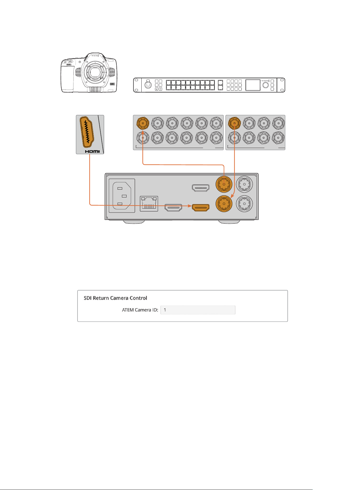
Blackmagic Pocket
Cinema Camera 6K Pro
BACKGROUND
CAMERA FG
PGM OUT PGM OUT MON OUT
RETURN MON IN
ETHERNET
Blackmagic Ultimatte 12 HD Mini
ATEM 2 M/E Constellation HD
1 3 5 7 9
2 4 6 8 10
11 13
12 14
SDI INPUTS
1 3 5 7
2 4 6 8 10
SDI OUTPUTS
6 7 8 9 CUT
16 17 18 19
10
20 AUTO
1 2 3 4 5
11 12 13 14 15
LOCK
MENU
SET
KEY 1
MIX
DSK 1
MIX
BARS
MIX
BLACK
WIPE
DSK2
MIX
FTB
MP 1
DIP
MP 2
DVE
PROD
TALK
ENG
TALK
CALL
PGM
MIX
5
Amphenol
4 2
1
3
PUSH
4 Open Blackmagic Ultimatte Setup on your computer and set the camera ID in the
‘camera control’ section of the ‘setup’ tab.
The camera ID number should match both the input number on your ATEM switcher
and the camera ID number in your camera’s menu. This ensures camera control and
tally is sent to the correct camera from the ATEM switcher.
Set the camera ID in Blackmagic Ultimatte Setup
67
Camera Control via Ultimatte 12 HD Mini

Connecting to a Network
Your Ultimatte main unit is shipped with a default IP address of 192.168.10.220 but you can
change this address if you need to. This is important when sharing multiple Ultimatte units on
your network and controlling them using Ultimatte Software Control on your computer or a
single Smart Remote 4.
TIP If you are connecting to more than one Ultimatte unit of the same type, it’s a
good idea to give each unit a discreet name to make them easy to identify. For more
information, refer to the ‘Blackmagic Ultimatte Setup’ section.
Setting the IP Address
You can change the IP address for an Ultimatte main unit using the front panel LCD menu or
Blackmagic Ultimatte Setup software. For more information on using the front panel menu,
referto the ‘using the LCD menu’ section.
To download the latest Ultimatte Setup software go to the Blackmagic Design support center
at
www.blackmagicdesign.com/support. For installation information refer to the ‘installing
Blackmagic ultimatte software’ section in this manual.
The ‘setup’ tab of Blackmagic Ultimatte Setup has
default settings for static IP and a ‘DHCP’ option
To change the IP address using Blackmagic Ultimatte Setup:
1 Connect the desired Ultimatte main unit to your computer via USB.
2 Launch Blackmagic Ultimatte Setup.
3 Click on the unit icon for your Ultimatte to open the setup settings.
4 In the ‘setup’ tab, enter the IP address, subnet mask and gateway settings.
68Connecting to a Network

On all Ultimatte models except Ultimatte 12, you can enable DHCP instead of assigning
an IP address manually. DHCP is a service on network servers that finds your Ultimatte
and assigns an IP address automatically. DHCP makes it easy to connect equipment via
Ethernet and make sure their IP addresses do not conflict with each other.
5 Click ‘save’ to confirm the settings.
Repeat the same process for each main unit you want to control. The subnet mask and gateway
should match your network settings and stay the same between all units, but make sure each
unit has its own unique IP address.
Setting the IP Address for your Smart Remote 4
If you are using a Smart Remote 4 and have updated each Ultimatte main unit’s IP address,
youwill need to configure the IP address on Smart Remote 4 so you can control the main units
on your network.
To set the IP address on your Smart Remote 4:
1 Reveal the Windows desktop by tapping on the info icon in the Smart Remote
touchscreen information and file control section. Now tap on the ‘options’ settings and
tap exit to desktop.
2 Navigate to the Windows network settings.
3 In the Ethernet related settings, select ‘change adapter options’.
4 Double tap on the ‘Ultimatte’ network to open the Ultimatte status window.
5 Tap on ‘properties’.
6 In the properties window, double tap on ‘internet protocol version 4 (TCP/IPv4) to open
its setting properties.
7 Select the ‘obtain an IP address automatically’ setting to let your Smart Remote find its
own IP address to join the network you are connected to. Or if you want to enter the
IP address, subnet mask and default gateway settings, select ‘use the following
IP address’ and set it manually.
8 Tap ‘OK’ to confirm the settings.
Double tap on the SR4 smart remote software icon to return to the touchscreen control panel.
Assigning Unit Numbers
Now that you are ready to control your Ultimatte main units, you need to assign them unit
numbers in the Ultimatte connection window.
To assign a number:
1 In Ultimatte Software Control, open the ‘ultimatte connection’ window from the top
menu bar. If you are using a Smart Remote 4, tap on a unit ID number.
2 In the ultimatte connection window click in each unit number list and select the name
ofthe Ultimatte that you want to allocate to that unit number.
TIP If you are connecting to any Ultimatte 12 units, click the ‘add via IP’ button and
enter the Ultimatte’s IP address.
69Connecting to a Network
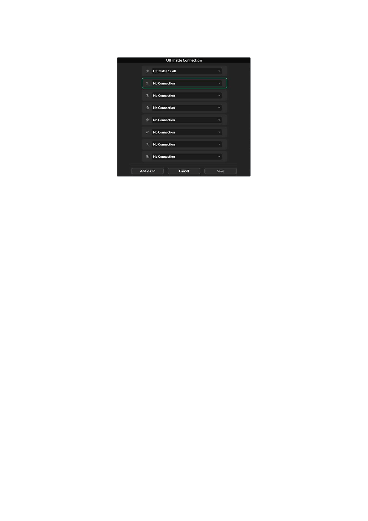
3 Click ‘save’ to confirm your selection.
If you look at the status bar, you will now see that unit number illuminated green. This means
theunit is online and ready to be controlled.
70Connecting to a Network
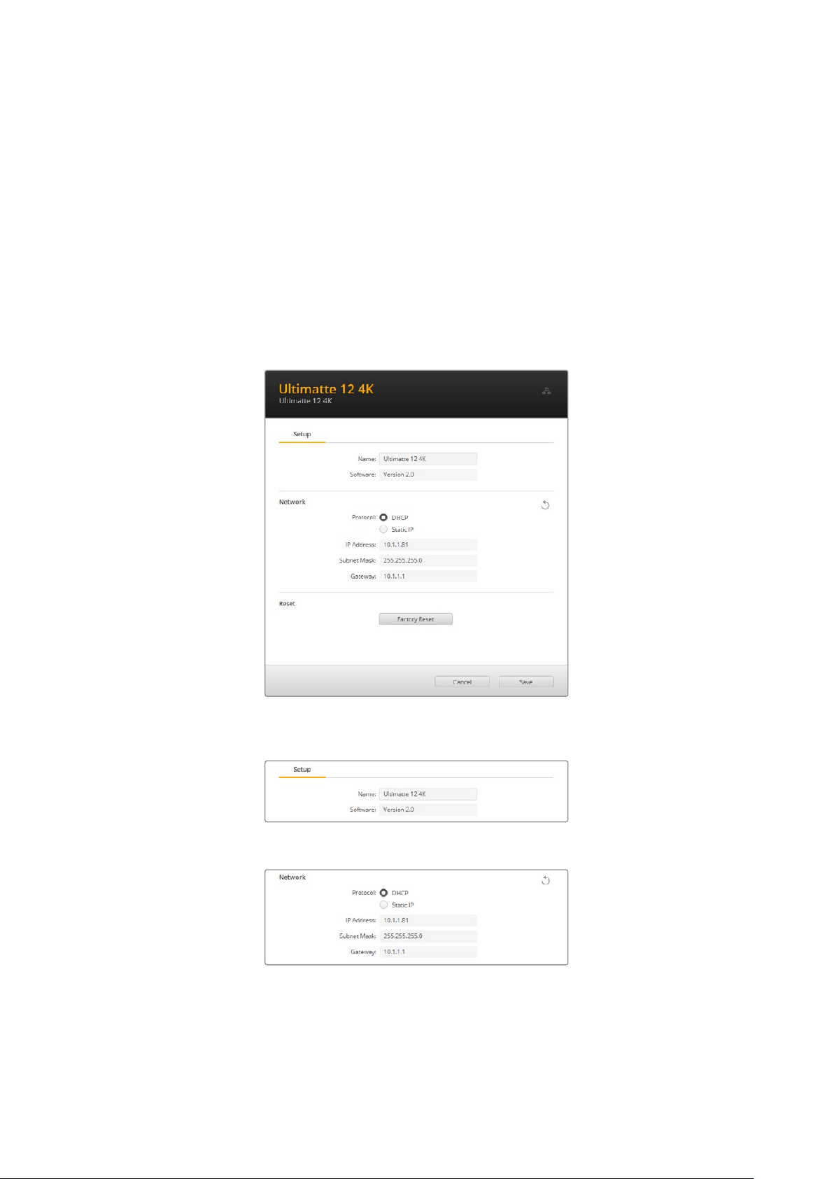
Blackmagic Ultimatte Setup
Blackmagic Ultimatte Setup is used to change settings and update the internal software in
yourUltimatte.
To use Ultimatte Setup:
1 Connect Ultimatte to your computer via USB or Ethernet.
2 Launch Ultimatte Setup. Your Ultimatte model will be named in the setup utility
home page.
3 Click on the circular ‘setup’ icon or the image of your Ultimatte to open the setup page.
Setup Page
If you have more than one Ultimatte, you may wish to give each unit a discrete name to make
them easy to identify. You can do this via the ‘name’ option.
Network
These settings allow you to configure options such as choosing between connecting to a
network over DHCP or using a static IP address. For more information on connecting your
Ultimatte to a network, refer to the ‘connecting to a network’ section.
71Blackmagic Ultimatte Setup
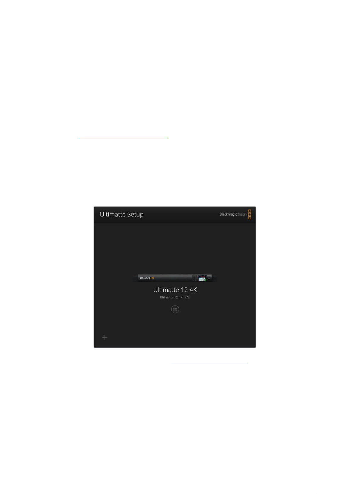
Reset
Reset your Ultimatte by clicking the ‘factory reset’ button. This will return your Ultimatte to its
original factory settings, any stills saved in the media pool will be deleted.
Updating the Internal Software
The setup utility lets you update your Ultimatte’s internal software in addition to configuring the
network settings.
To update the internal software:
1 Download the newest Blackmagic Ultimatte Setup installer from
www.blackmagicdesign.com/support.
2 Run the Blackmagic Ultimatte Setup installer on your computer and follow the onscreen
instructions.
3 After installation is complete, connect your Ultimatte to your computer via USB
or Ethernet.
4 Launch Blackmagic Ultimatte Setup and follow any onscreen prompt to update the
internal software. If no prompt appears, the internal software is up to date and there is
nothing further you need to do.
Download the latest setup utility for your Blackmagic Ultimatte from the
Blackmagic Design support center at www.blackmagicdesign.com/support
72Blackmagic Ultimatte Setup
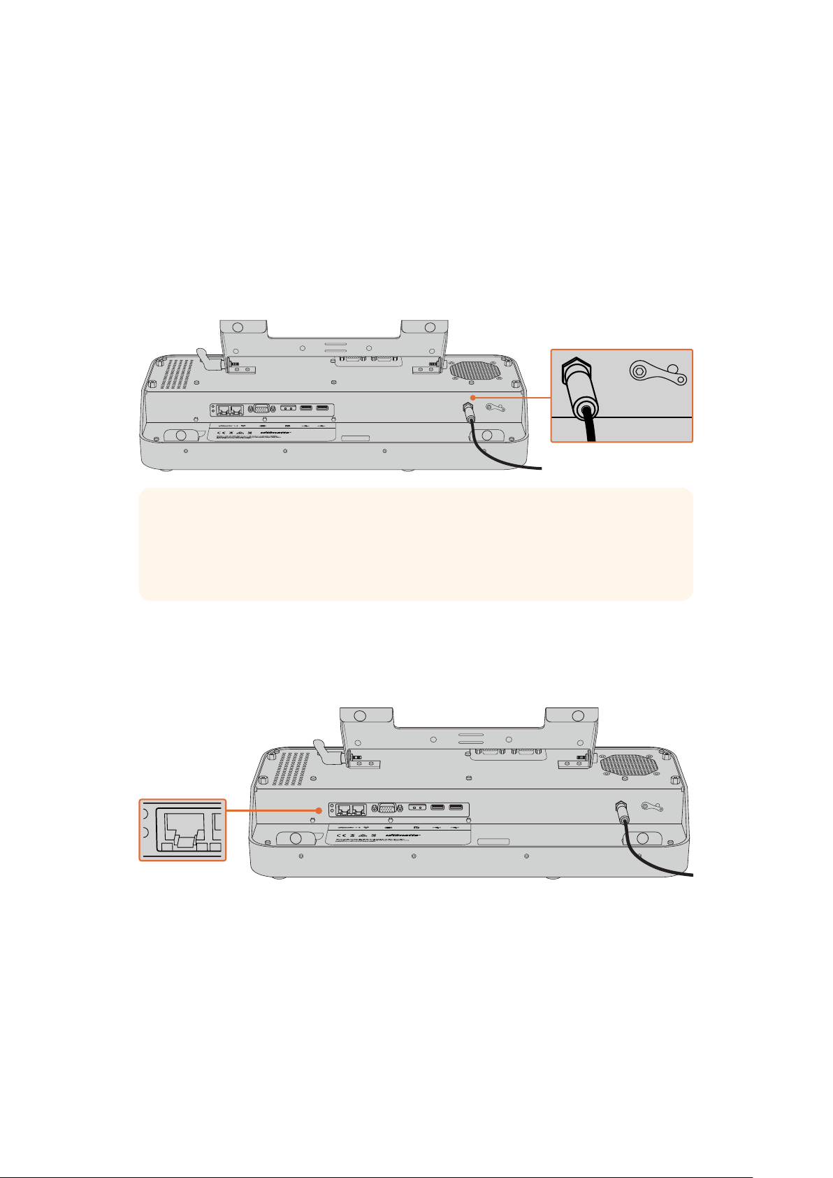
Using Smart Remote 4
If you are using an optional Smart Remote 4 to control your Ultimatte, you will first need to install
the latest version of Ultimatte Software Control. For more information, refer to the ‘updating
your Smart Remote 4’ section.
Connecting Power
Plug the included power adapter into the DC power input on the rear panel. The screw ring is
used to secure the connector to the port.
TIP The power adapter’s outside screw ring also serves as the negative contact,
with the positive contact being the center pin of the connector. If you want to secure
a ground connection to the chassis of your Smart Remote 4, you can attach it to the
terminal lug located next to the power input.
Connecting to Ultimatte
Connect an Ethernet cable from the rear panel of your Ultimatte to the left side Ethernet port of
Smart Remote 4.
Plug your Ultimatte main unit into the Smart Remote 4’s left side Ethernet port
73
Using Smart Remote 4

Turning on Smart Remote 4
To turn the smart remote on, press the power button located at the top left corner of the
control panel.
ONLINE / ON AIR
QUICK LOAD
QUICK SAVE
ALT
1 2 3 4
5 6 7 8
UNITS
FILE
CLEAR
SMART REMOTE 4
1 2 3 4 5
When power is activated, the power button will illuminate blue and the smart remote will initiate
the software start up sequence
At its heart, Smart Remote 4 is a small portable computer running the Windows® operating
system. When the start up sequence is complete, the Ultimatte Software Control will launch
andthe control panel will appear on the touchscreen.
Updating your Smart Remote 4
The first step to updating your Smart Remote 4 is to uninstall the SR4 software from your
smart remote.
Tap on the ‘info’ icon in the Smart Remote 4 file control section of the control panel to find your
current SR4 software version number. Follow the sections below based on whether you have
SR-4 v1.0.5 or earlier or if you have SR-4v1.1 or later.
Uninstalling Software
Before uninstalling the SR4 software, ensure the application is not running.
To quit the SR4 software:
1 Tap on the ‘info’ icon in the smart remote 4 file control section in the control panel.
MATTE MENU
2 In the ‘options’ tab, tap on the ‘exit to desktop’ button.
74Updating your Smart Remote 4

3 Now that the desktop is visible, tap on the ‘up’ arrow in the Windows tray.
4 Tap and hold the Ultimatte SR4 icon for 2 seconds then release. The ‘quit’ icon
willappear. Simply tap on the ‘quit’ icon to close the application.
To uninstall SR4 v1.1 or later:
1 Press the ‘start’ button in the task bar and select ‘settings’.
2 In the settings window, select ‘system’ from the menu and choose the ‘apps &
features’ option.
3 In the ‘apps & features’ window, scroll through the list of apps and locate the Ultimatte
SR4 software.
4 Select the Ultimatte SR4 software from the list and choose ‘uninstall’.
5 Follow the prompts to uninstall the software.
To uninstall SR4 v1.0.5 or earlier:
1 Tap and hold the Windows logo in the bottom left corner, then tap on ‘file explorer’.
Tap and hold on the Windows logo,
then tap file explorer
75
Updating your Smart Remote 4
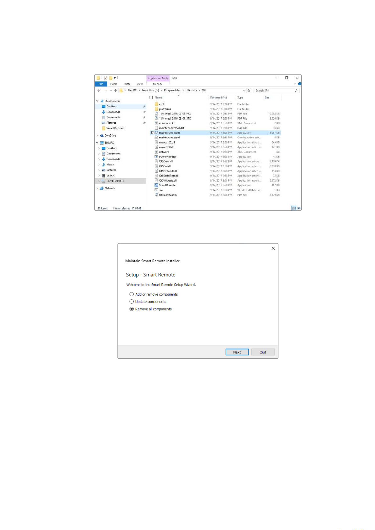
2 In file explorer, navigate to: C:\Program Files\Ultimatte\SR4, and double tap
onthemaintenance application labelled, ‘maintenancetool.exe’
Browse ‘local disk C:\’ and double tap on the required folders to open their contents
3 On the maintenance application window, select ‘remove all components’ and tap ‘next’.
Select ‘remove all components’ and tap ‘next’
4 The maintenance application will now let you know it is ready to uninstall. Tap ‘uninstall’
and allow the application to make changes to your Smart Remote 4 by tapping ‘yes’.
5 Tap ‘finish’ on the ‘completing the smart remote wizard’ window.
The Ultimatte Smart Remote 4 software has now been uninstalled.
76Updating your Smart Remote 4
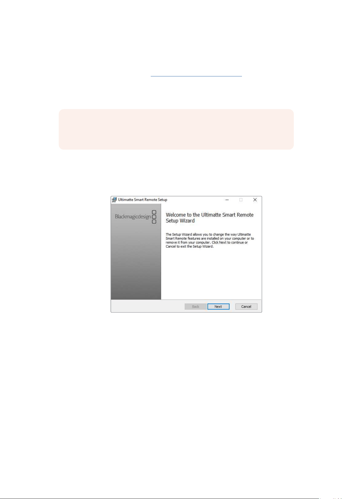
Installing Ultimatte Smart Remote Setup
The first step is to download the latest Ultimatte Smart Remote 4 Setup software from the
Blackmagic Design support center at www.blackmagicdesign.com/support. Copy and paste the
Smart Remote .msi file onto a portable USB storage unit, for example a USB flash drive.
Plug the USB drive into the USB port on the front of your Smart Remote 4. Smart Remote 4 will
automatically read the USB drive and open the file explorer.
NOTE The portable storage drive used to install the software on your smart remote
must be formatted as the master boot record using one single partition. Your Smart
Remote 4 recognizes NTFS, exFAT and FAT32 formats.
To install the software:
1 Double tap on the smart remote installer icon in the storage drive.
2 Tawp ‘next’ in the setup wizard and follow the prompts until you reach the
‘install’ option.
3 Tap ‘install’ and allow the installer to make changes to your Smart Remote 4 by tapping
‘yes’ when prompted.
77Updating your Smart Remote 4
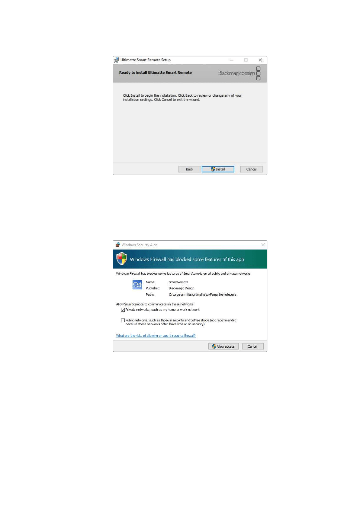
4 Tap ‘finish’ to complete the installation and ‘yes’ to restart your Smart Remote 4.
Your Smart Remote 4 will restart and automatically launch the latest version of the
Ultimatte Smart Remote 4 control panel.
5 A Windows dialogue box will appear prompting you to allow Smart Remote to
communicate over a network. Select ‘private networks, such as my home or work
network’ and tap ‘allow access’.
Connecting a USB Keyboard and Mouse
If you want to control your Ultimatte Smart Remote 4 using a keyboard and a mouse, simply
plug them into the USB ports on the rear panel. Your Smart Remote 4 will automatically detect
the keyboard and mouse as a plug and play device and you can control your Smart Remote 4
as if using a Windows PC.
78Updating your Smart Remote 4

Rack Installation
Ultimatte 12 8K and 4K models can be installed into a broadcast rack or road case using
theincluded Ultimatte rack mount kit.
If you are using your Ultimatte on a desk, you can fit the supplied rubber feet to the base.
Simplystick a rubber foot to each corner of the underside, taking care not to cover any screws.
The rack mount kit contains the following items:
2 x Front Rack Ears
Attach the front rack ears to the outside
front edge of the unit.
2 x Rear Rack Ears
Attach the rear rack ears to the outside
rear edge of the unit.
2 x Chassis Bumpers
Two chassis bumpers can be attached to
each side of the chassis. These bumpers
are designed to protect the rear connectors.
They can also provide strain relief for cables
that are connected to the unit.
Screws
12 x M4 Countersunk
For front rack ears
andchassis bumpers
6 x M4 Flathead Screws
For rear rack ears
79Rack Installation
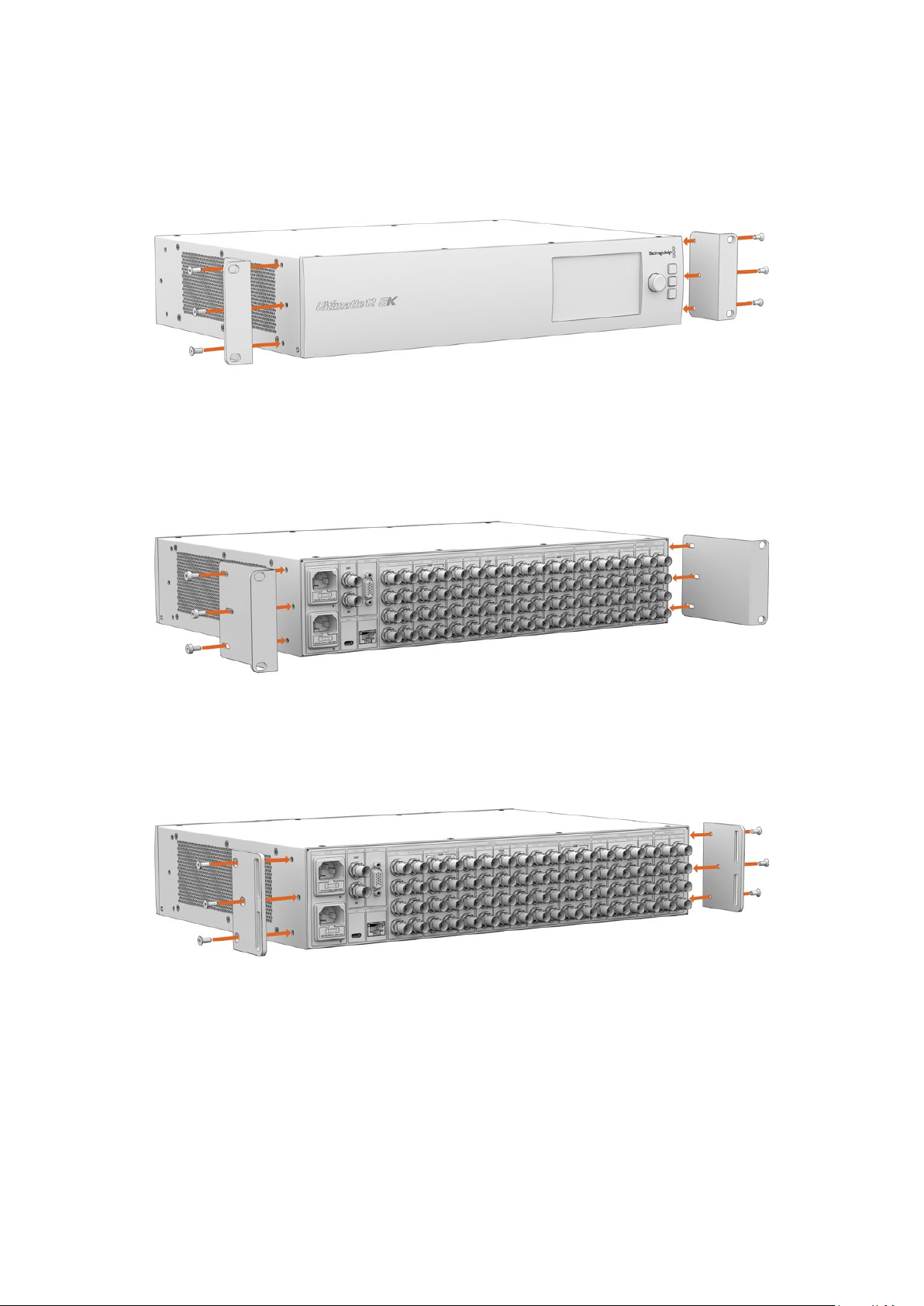
Installing Front Rack Ears
Using a 2mm hex key, attach the rack ears to each side of the unit using the supplied
M4countersunk screws.
Installing Rear Rack Ears
Using a 3mm hex key, attach the rear rack ears to Ultimatte 12 8K using the supplied
M4flathead screws.
Installing Chassis Bumpers
Install the optional chassis bumpers using the supplied M4 countersunk screws.
80Rack Installation
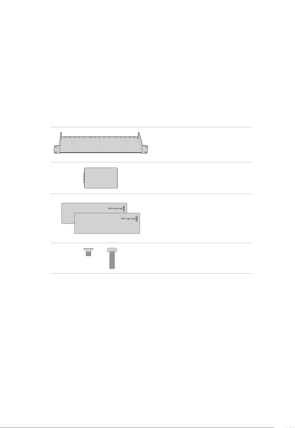
Rack Mounting
Teranex Mini Rack Shelf is a 1RU shelf that lets you install Blackmagic Ultimatte 12 HD Mini and
Ultimatte 12 HD models into a broadcast rack or road case.
Blackmagic Ultimatte 12 HD Mini and Ultimatte 12 HD are small, so you can install them next
to other Blackmagic Design equipment that share a similar form factor, such as Teranex Mini
converters, Blackmagic MultiView 4 and Blackmagic Web Presenter. For example, installing a
Blackmagic Ultimatte 12 HD Mini together with a HyperDeck Studio HD Mini means you can
record your program or monitor output. This modular design lets you build your own custom
video solutions that are portable and easy to use.
The Teranex Mini Rack Shelf Kit contains the following:
1 x Teranex Mini Rack Shelf
1 x 1/6 rack width blanking panel
Use the 1/6 blanking panel when mounting 1/2 rack
width products with a 1/3 width unit or blanking panel
2 x 1/3 rack width blanking panel
Use 1/3 width blanking panels when mounting single
products
Screws
8 x M3 5mm
Countersunk mounting
screws
2 x M3 10mm
Flat nylon screws for 1/6
blanking panels
To mount Ultimatte 12 HD Mini and Ultimatte 12 HD models:
1 The first step to mount any product to the Teranex Mini rack shelf is to remove the
rubber feet from your device.
2 With both the rack and device upside down, line up the pre drilled holes on the rack
with the threaded mounting holes on the device. This will be via two central mounting
points on 1/3 width products or up to three mounting points on larger products such
as HyperDeck Studio HD Plus. The location of the mounting points will depend on
whether you are installing the unit on the left or right of the rack.
81Rack Mounting
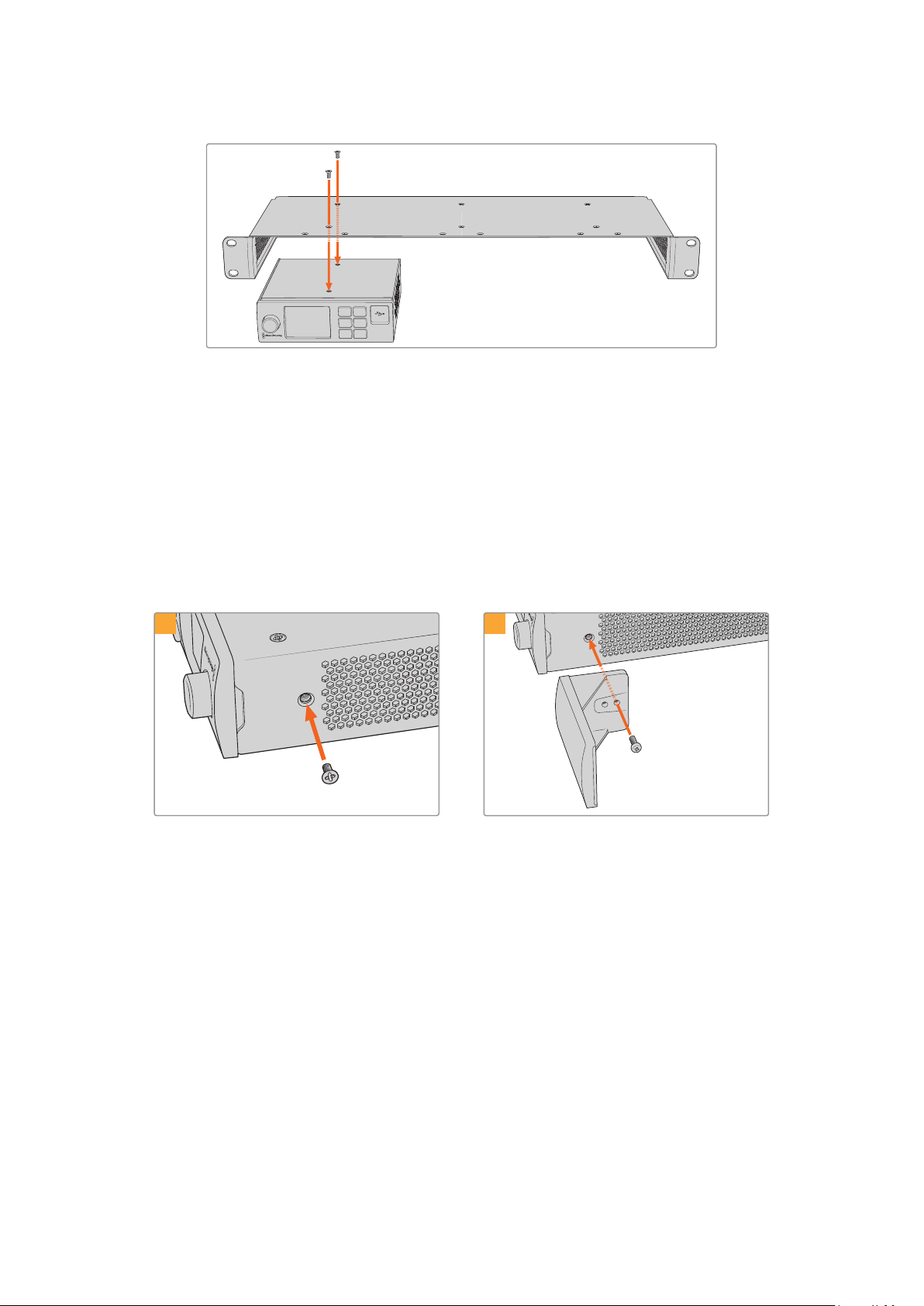
1 MENU
2 SET
3 LOCK
3 Using the supplied M3 5mm countersunk screws, mount the device to the rack.
4 Once you’ve installed your HyperDeck or other Blackmagic Design product, turn the
rack shelf right side up and install into your equipment rack.
Blanking panels can be used to fill spaces in your rack that may be left available, such as when
mounting a HyperDeck Studio HD Mini with a Blackmagic Web Presenter.
To attach the 1/6 blanking panel:
The 1/6 blanking panel is designed to be attached to 1/2 rack width products, such as
HyperDeck Studio HD Plus when they are mounted solo, or with a 1/3 rack width product such
as a Blackmagic Web Presenter. Mount the panel to the side of the device towards the center
ofthe rack to allow for airflow between units.
Remove the 5mm M3 screw near the front
ofthedevice.
Line up the blanking panel and attach using the
supplied M3 10mm nylon screw.
1
2
To attach the side 1/3 width blanking panel:
To install the 1/3 width blanking panel, line up the screw holes and anchor point with the shelf.
The 1/3 width blanking panel can be used on either side or the center of the rack. Screw the
panel to the shelf using two of the supplied M3 5mm countersunk screws.
For deeper products, such as the Blackmagic Studio Converter, use the Blackmagic Universal
Rack Shelf.
82Rack Mounting

Developer Information
Controlling Ultimatte using Telnet
The Blackmagic Ultimatte 12 Ethernet Protocol gives you the freedom to build your own
custom control solutions for your Ultimatte 12. For example, you can create your own software
application and control your Ultimatte via Ethernet from your computer.
The first step is to connect your Ultimatte to your computer via Ethernet. You can do this by
connecting Ultimatte to the same network your computer is connected to, or you can connect
Ultimatte directly to your computer.
NOTE If your Blackmagic Ultimatte is connected directly to your computer, set your
computer to a manual static IP address. Set the first three blocks of numbers in the
IPaddress tomatch your Ultimatte and set the subnet mask to 255.255.255.0. You can
leave thegateway or router setting blank as it will not be used in a direct connection
between your computer and Ultimatte.
If your network settings are set correctly, you can now open the Terminal application on
MacOS, or enable Telnet command line utilities on Windows and enter Ultimatte control
protocol commands. These commands can be programmed into your application and triggered
by related items on a custom user interface of your own design.
Below is a basic example of using Telnet to change the backing color, restore to factory
defaults, and adjust the matte density control.
1 In the Terminal application, type the following:
telnet (IP address of main unit (space) port number)(enter)
For example: telnet 192.168.10.220 9998
Press ‘enter’.
A list of status information will appear and you are ready to control your Ultimatte.
2 Now type the following:
control: (press enter)
backing color: blue (press enter twice)
Terminal will acknowledge the action with ‘ack’ and confirm it so you know your setting
has been performed.
You have now changed Ultimatte’s backing color to blue.
3 To restore to factory defaults, type the following:
control: (press enter)
factory defaults: yes (press enter twice)
This restores your Ultimatte to factory default settings and performs an automatic
composite.
4 To adjust the matte density setting, type the following:
control: (press enter)
matte density: 273 (press enter twice)
Terminal will acknowledge and confirm the action.
You have now adjusted the matte density setting.
83Developer Information

5 To exit Telnet:
Hold down the control button and press the ‘]’ key. The Telnet prompt will appear.
Type the following:
quit(press enter)
A status message will appear confirming the connection is closed.
Blackmagic Ultimatte 12 Ethernet Protocol
Version 2.0
If you are a software developer you can use Ultimatte Ethernet Protocol to construct devices
that integrate with our products. Here at Blackmagic Design our approach is to open up our
protocols and we eagerly look forward to seeing what you come up with!
Overview
The Blackmagic Ultimatte Ethernet Protocol is a text based protocol that is accessed by
connecting to TCP port 9998 on an Ultimatte.
Ultimatte sends information in blocks. Each block has an identifying header in all caps, followed
by a full colon. A block spans multiple lines and is terminated by a blank line. Each line in the
protocol is terminated by a newline character.
Upon connection, the Ultimatte device sends a complete update of its status. After the initial
status transmission, status updates are sent every time the Ultimatte device’s status changes.
To be resilient to future protocol changes, clients should ignore blocks they do not recognize,
up to the trailing blank line. Within existing blocks, clients should ignore lines that they do not
recognize.
Protocol Preamble
The first block sent by Ultimatte is always the protocol preamble:
PROTOCOL PREAMBLE:
↵
Ve rsio n: 2.0
↵
↵
The version field indicates the protocol version. When the protocol is changed in a backwards
compatible way, the minor version number will be updated. If incompatible changes are made,
the major version number will be updated.
Identity
The next block contains information about the device identity.
IDE N TI TY:
↵
Model: Ultimatte 12 8K
↵
Label: Ultimatte 12 8K
↵
Unique ID: 12345678
↵
↵
Network Information
There are two network blocks. The first describes the general network information and the
second describes the network interface details.
NETWORK:
↵
Interface count: 1
↵
Default Interface: 0
↵
Static DNS Ser vers: 8.8.8.8, 8.8.4.4
↵
Current DNS Ser ve rs: 8.8.8.8, 8.8.4.4
↵
↵
84Developer Information

NETWORK INTERFACE 0:
↵
Name: Cadence GigE Ethernet MAC
↵
Priority: 0
↵
MAC Address: xx.xx.xx.xx.xx.xx
↵
Dyna micIP: false
↵
Cu rre nt A dd re sses: 10.0.0.2/255.255.255.0
↵
Cu rre nt G at ew ay: 10.0.0.1
↵
Static A d dr esses: 10.0.0.2/255.255.255.0
↵
Static G ate way: 10.0.0.1
↵
↵
Version Information
The version information describes the hardware and software version numbers and identifiers
of the device. For example, the “Product ID” field contains the hexadecimal USB Product
Identifier.
VERSION:
↵
Product ID: BE84
↵
Hardware Version: 0100
↵
Software Version: 09A89B7A
↵
Software Release: 2.0
↵
↵
Device Information
The next block contains general information about the connected Ultimatte device.
DEVICE:
↵
Video Format: 1080p60
↵
Reference Source: Foreground
↵
FG In: Locked
↵
BG In: Locked
↵
MONITOR In: Locked
↵
G MATTE In: Locked
↵
H MATTE In: Locked
↵
REFIn: Locked
↵
BG MATTE In: Locked
↵
LAYER In: Locked
↵
LAYER MATTE In: Locked
↵
↵
NOTE Some Ultimatte models will only have a subset of the above-mentioned inputs.
For example, the Ultimatte 12 HD Mini only has the following inputs:
Foreground input (FG In), and
Background input (BG In).
Similarly, the Ultimatte 12 HD only has the following inputs:
Foreground input (FG In),
Background input (BG In),
Garbage Matte input (G MATTE In),
Holdout Matte input (H MATTE In),
Monitor Input (MONITOR In), and
Reference Input (REF In).
85Developer Information

Video Formats Information
The Video Formats blocks lists the video formats supported by the device. See the Video
Format Control list to find the formats supported by each device.
VIDEO FORMATS:
↵
auto detect
↵
525.59.94 N TSC 4:3
↵
625i50 PAL 4:3
↵
720p60
↵
...
↵
Initial Status Dump
The next eleven blocks provide the control values, control default values, current file, file list,
the GPI lists, the Frame Buffer Image List and Frame Buffer State.
CONTROL:
↵
Matte Density: 0
↵
Red Density: 0
↵
Green Density: 0
↵
...(Full list in Controls section)
↵
CONTROL DEFAULT:
↵
Matte Density: 0
↵
Red Density: 0
↵
Green Density: 0
↵
...(Full list in Controls section)
↵
CU RRENT FILE:
↵
Filename
↵
↵
FILE LIST:
↵
File 1
↵
File 2
↵
↵
GPI LIST:
↵
ID: 1
↵
Index: 0
↵
File 1
↵
File 2
↵
↵
NOTE The Ultimatte 12 HD Mini does not have GPI inputs, so this block is not available
on that device.
The IMAGE LIST block contains the filenames of images that are currently stored on the device.
These images can be assigned to Frame Buffer inputs.
IM AGE LIST:
↵
Image 1
↵
Image 2
↵
↵
86Developer Information

The FRAME BUFFER block contains the status of the Frame Buffers on the device.
Thisinformation will show:
How many image buffers are available,
whether a frame buffer is enabled and has an image buffer assigned to it, and
how frame buffer transitions are set up for those frame buffers that support transitions.
NOTE Frame Buffer Duration time is in milliseconds.
FRAME BUFFER:
↵
Number Of Frame Buffers: 46
↵
BG 1 Frame Buffer Enable: off
↵
BG 1 Frame Buffer Index: 0
↵
LY 1 Frame Buffer Enable: off
↵
LY 1 Frame Buffer Index: 0
↵
BG 2 Frame Buffer Enable: off
↵
BG 2 Frame Buffer Index: 0
↵
LY 2 Frame Buffer Enable: off
↵
LY 2 Frame Buffer Index: 0
↵
GM Frame Buffer Enable: off
↵
GM Frame Buffer Index: 0
↵
HM Frame Buffer Enable: off
↵
HM Frame Buffer Index: 0
↵
BG Frame Buffer Mix: 0
↵
LY Frame Buffer Mix: 0
↵
BG Transition Duration: 0
↵
LY Transition Duration: 0
↵
Frame Buffer 1: Image 1
↵
Frame Buffer 2: Image 2
↵
...
↵
End Prelude
The final block of the status dump sent by Ultimatte is always end prelude:
END PRELUDE:
↵
↵
Status Updates
When any Control is changed on an Ultimatte device, the Ultimatte device replies with the
applicable status block to all connected clients, containing only the items that have changed.
For example, if Matte Density has been changed, the following block will be sent:
CONTROL:
↵
Matte Density: 0
↵
↵
If multiple items are changed, multiple items may be present in the update:
CONTROL:
↵
Matte Density: 0
↵
Red Density: 0
↵
↵
These notifications are sent whether the change originated from the front panel, or from any
other connected client.
87Developer Information

Requesting Changes
To update a Control the client should send a block of the same form Ultimatte sends when
its status changes. For example, to change Matte Density to 100, the client should send the
following block:
CONTROL:
↵
Matte Density: 100
↵
↵
The block must be terminated by a blank line. On receipt of a blank line, Ultimatte will either
acknowledge the request by responding:
ACK
↵
↵
or indicate that the request was not understood by responding:
NAK
↵
↵
After a positive response, the client should expect to see a status update from Ultimatte
showing the status change. This is likely to be the same as the command that was sent, but
if the request could not be performed, or other changes were made simultaneously by other
clients, there may be more updates in the block, or more blocks. Simultaneous updates could
cancel each other out, leading to a response that is different to that expected.
In the absence of simultaneous updates, a simple control change will result in the following
protocol exchange:
CONTROL:
↵
Matte Density: 0
↵
↵
ACK
↵
↵
CONTROL:
↵
Matte Density: 0
↵
↵
The asynchronous nature of the responses means that a client should never rely on the desired
update actually occurring and must simply watch for status updates from Ultimatte and use only
these to update its local representation of Ultimatte’s state.
A client may also request Ultimatte to change a control by a relative amount. For example,
to change Matte Density by 10, the client should send the following block:
CONTROL:
↵
Offset Matte Density: 10
↵
↵
Only controls with numerical ranges support this relative mode.
Requesting a Status Dump
The client may request that Ultimatte resend the complete state of any status block by sending
the header of the block, followed by a blank line. In the following example, the client requests
Ultimatte resend the control status:
CONTROL:
↵
↵
ACK
↵
↵
88Developer Information

CONTROL:
↵
Matte Density: 0
↵
Red Density: 0
↵
Green Density: 0
↵
...(Full list in Controls section)
↵
File System
The client may request that Ultimatte load, save, delete, or rename a file. To load a file the client
should send the following block:
FILE:
↵
Load: <filename>
↵
↵
Ultimatte will respond with an ACK followed by a Current File block or a Message block.
To save, delete, or rename a file the client should send one of the following blocks:
FILE:
↵
Save: <filename>
↵
↵
FILE:
↵
Delete: <filename>
↵
↵
FILE:
↵
Rename: <filename>
↵
To: <filena me>
↵
↵
In each case Ultimatte will respond with an ACK followed by a File List block or a
Message block.
GPI Event List
The client may request that Ultimatte add, insert or remove an event to a GPI Event List by
sending an Insert GPI Event or Remove GPI Event command, followed by a blank line.
For example, to insert an event, the client should send the following block:
GPI:
↵
ID: 1
↵
Insert: <filename>
↵
At: -1
↵
{The insertion index. A ‘-1’ represents the end of the list}
↵
To remove an event a client would send the following block:
GPI:
↵
ID: 1
↵
Remove: 1
↵
{Event index to remove. A ‘0’ will delete all events}
↵
To set the current event index a client would send the following block:
GPI:
↵
ID: 1
↵
Index: 1
↵
↵
89Developer Information

Ultimatte will respond with an ACK message followed by either a GPI List Block or a
Message Block.
GPI LIST:
↵
ID: 1
↵
Index: 0
↵
File 1
↵
File 2
↵
...
↵
or
MESSAGE:
↵
Warning: Event limit exceeded
↵
↵
Frame Buffer
The client may request that the Ultimatte device assign a pre-loaded image from its Media Pool
into a particular frame buffer and enable/disable the frame buffer. To assign and enable an
image to the BG frame buffer the following commands are required:
FRAME BUFFER:
↵
BG 1 Frame Buffer Index: 1
↵
BG 1 Frame Buffer Enable: on
↵
↵
To disable the frame buffer only the enable command is required:
FRAME BUFFER:
↵
BG 1 Frame Buffer Enable: on
↵
↵
NOTE The Telnet interface does not currently provide loading or removing images
in the Media Pool. This has to be done from either a Smart Remote 4, or using the
Software Control application. Refer to the ‘using the media pool’ section of this manual
for more information.
Camera Control
Ultimatte 12 HD Mini can be used to control an attached camera via SDI or HDMI, please refer
to the ‘Camera Control via Ultimatte 12 HD Mini’ section for more information. For SDI Camera
Control, the Ultimatte device’s Camera ID may be changed using the CAMERACONTROL block:
CA MER ACONTROL:
↵
Camera Id: 1
↵
↵
NOTE This control block is only available on the Ultimatte 12 HD Mini.
90Developer Information

Controls
Matte Density 0-10000
Black Gloss 0-10000
Blue Density 0-10000
Green Density 0-10000
Red Density 0-10000
Shadow Level 0-10000
Shadow Threshold 0-10000
Matte Correct Horizontal Size 0-6
Matte Correct Vertical Size 0-3
Cursor X 0-10000
Cursor Y 0-10000
Cursor 2 X 0-10000
Cursor 2 Y 0-10000
Veil Master 0-10000
Veil Red 0-10000
Veil Green 0-10000
Veil Blue 0-10000
Veil Correct Horizontal Size 0-6
Veil Correct Vertical Size 0-6
1
Wall Color Red 0-10000
Wall Color Green 0-10000
Wall Color Blue 0-10000
Floor Color Red 0-10000
Floor Color Green 0-10000
Floor Color Blue 0-10000
Cleanup Level 0-10000
Cleanup Dark Recover 0-10000
Cleanup Light Recover 0-10000
Cleanup Strength 0-10000
GM Cleanup Level 0-10000
GM Cleanup Dark Recover 0-10000
GM Cleanup Light Recover 0-10000
GM Cleanup Strength 0-10000
Correction Level 0-10000
Noise Level 0-10000
Black Balance 0-10000
Gray Balance 0-10000
91Developer Information

Controls
White Balance 0-10000
Flare Level 0-10000
Cool 0-10000
Skin Tone 0-10000
Light Warm 0-10000
Dark Warm 0-10000
Flare Correct Horizontal Size 0-6
Flare Correct Vertical Size 0-6
1
Ambiance Master 0-10000
Ambiance Red 0-10000
Ambiance Green 0-10000
Ambiance Blue 0-10000
Ambiance Strength 0-10000
Direct Light Red 0-10000
Direct Light Green 0-10000
Direct Light Blue 0-10000
Direct Light Mix 0-10000
Vertical Blur 0-10000
FG Saturation Red 0-10000
FG Saturation Green 0-10000
FG Saturation Blue 0-10000
FG Saturation Master 0-10000
FG Contrast Red 0-10000
FG Contrast Green 0-10000
FG Contrast Blue 0-10000
FG Contrast Master 0-10000
FG Black Red 0-10000
FG Black Green 0-10000
FG Black Blue 0-10000
FG Black Master 0-10000
FG White Red 0-10000
FG White Green 0-10000
FG White Blue 0-10000
FG White Master 0-10000
FG Contrast Crossover 0-10000
Fade Mix 0-10000
BG Saturation Red 0-10000
92Developer Information

Controls
BG Saturation Green 0-10000
BG Saturation Blue 0-10000
BG Saturation Master 0-10000
BG Contrast Red 0-10000
BG Contrast Green 0-10000
BG Contrast Blue 0-10000
BG Contrast Master 0-10000
BG Black Red 0-10000
BG Black Green 0-10000
BG Black Blue 0-10000
BG Black Master 0-10000
BG White Red 0-10000
BG White Green 0-10000
BG White Blue 0-10000
BG White Master 0-10000
BG Contrast Crossover 0-10000
BG Filter 0-10000
Test Signal Master 0-10000
Test Signal Red 0-10000
Test Signal Green 0-10000
Test Signal Blue 0-10000
LY Saturation Red 0-10000
LY Saturation Green 0-10000
LY Saturation Blue 0-10000
LY Saturation Master 0-10000
LY Contrast Red 0-10000
LY Contrast Green 0-10000
LY Contrast Blue 0-10000
LY Contrast Master 0-10000
LY Black Red 0-10000
LY Black Green 0-10000
LY Black Blue 0-10000
LY Black Master 0-10000
LY White Red 0-10000
LY White Green 0-10000
LY White Blue 0-10000
LY White Master 0-10000
93Developer Information

Controls
LY Contrast Crossover 0-10000
LY Filter 0-10000
LY Test Signal Master 0-10000
LY Test Signal Red 0-10000
LY Test Signal Green 0-10000
LY Test Signal Blue 0-10000
LY Fade Mix 0-10000
Lighting Level Red 0-10000
Lighting Level Green 0-10000
Lighting Level Blue 0-10000
Lighting Level Master 0-10000
Lighting Minimum Level 0-10000
Window Position Top 0-{Based on Video Format}
Window Position Bottom 0-{Based on Video Format}
Window Position Left 0-{Based on Video Format}
Window Position Right 0-{Based on Video Format}
Window Softness Top 0-10000
Window Softness Bottom 0-10000
Window Softness Left 0-10000
Window Softness Right 0-10000
Window Skew Top 0-10000
Window Skew Bottom 0-10000
Window Skew Left 0-10000
Window Skew Right 0-10000
Window Skew Offset Top 0-10000
Window Skew Offset Bottom 0-10000
Window Skew Offset Left 0-10000
Window Skew Offset Right 0-10000
Transition Rate 1-120
BM Process Horizontal 0-3
BM Process Vertical 0-3
BM Filter 0-10000
BM Input Level 0-10000
BM Input Offset 0-10000
GM Process Horizontal 0-3
GM Process Vertical 0-3
GM Filter 0-10000
94Developer Information

Controls
GM Input Level 0-10000
GM Input Offset 0-10000
HM Process Horizontal 0-3
HM Process Vertical 0-3
HM Filter 0-10000
HM Input Level 0-10000
HM Input Offset 0-10000
LM Process Horizontal 0-3
LM Process Vertical 0-3
LM Filter 0-10000
LM Input Level 0-10000
LM Input Offset 0-10000
Noise Cursor X 0-10000
Noise Cursor Y 0-10000
FG Input Frame Delay 0-14
FG Input U Position 0-10000
FG Input V Position 0-10000
FG Input UV Position 0-10000
Talent Highlight Level** 0-10000
Monitor Highlight Level 0-10000
Matte Out Level 0-10000
Output Offset -1500-+1500
GP Out Delay* 1-120
GP 1 Input Delay* 1-120
GP 2 Input Delay* 1-120
GP 3 Input Delay* 1-120
GP 4 Input Delay* 1-120
GP 5 Input Delay* 1-120
Matte Enable On/Off
Screen Correct On/Off
GM Cleanup Enable On/Off
Noise Enable On/Off
Noise Cursor Enable On/Off
FG Freeze On/Off
FG Advanced Contrast Enable On/Off
Advanced Flare Enable On/Off
HM Flare Enable On/Off
95Developer Information
Controls
Ambiance Enable On/Off
BG Gradient Enable On/Off
BG Freeze On/Off
BG Advanced Contrast Enable On/Off
BG Test Signal Enable On/Off
LY Input Enable On/Off
LY Advanced Contrast Enable On/Off
LY Fre eze* * On/Off
LY Test Signal Enable On/Off
Lighting Enable On/Off
Window Enable On/Off
Window BM Enable On/Off
Window GM Enable On/Off
Window HM Enable On/Off
Window LM Enable On/Off
Window Invert On/Off
Wall Cursor Position Enable On/Off
Floor Cursor Position Enable On/Off
Dual Cursor On/Off
Manual Color Enable On/Off
Custom Powerup(deprecated) On/Off
BM Enable On/Off
BM Invert On/Off
BM Process Invert On/Off
BM Freeze** On/Off
GM Enable On/Off
GM Invert On/Off
GM Process Invert On/Off
GM Freeze* On/Off
HM Enable On/Off
HM Invert On/Off
HM Process Invert On/Off
HM Freeze* On/Off
LM Invert On/Off
LM Process Invert On/Off
Monitor To Program On/Off
Monitor To Talent** On/Off
96Developer Information

Controls
Fill Linear Mix Correction* On/Off
Talent Mirror** On/Off
Monitor Cascade On/Off
Matte Out Invert* On/Off
On Air Enable On/Off
On Air Lockout On/Off
Matte View Range On/Off
Matte View Invert On/Off
Monitor Out RGB On/Off
Monitor Out Red Only On/Off
Monitor Out Green Only On/Off
Monitor Out Blue Only On/Off
GP Out Save* On/Off
Quickload 1 On/Off
Quickload 2 On/Off
Quickload 3 On/Off
Quickload 4 On/Off
Quickload 5 On/Off
Quicksave 1 On/Off
Quicksave 2 On/Off
Quicksave 3 On/Off
Quicksave 4 On/Off
Quicksave 5 On/Off
GP 1 Input Enable* On/Off
GP 2 Input Enable* On/Off
GP 3 Input Enable* On/Off
GP 4 Input Enable* On/Off
GP 5 Input Enable* On/Off
GP 1 High Enable* On/Off
GP 2 High Enable* On/Off
GP 3 High Enable* On/Off
GP 4 High Enable* On/Off
GP 5 High Enable* On/Off
Tally Active On/Off {Read Only}
3G SDI level A/B
Color Space* Rec.709/Rec.2020
Filter Mode Median/Average
97Developer Information
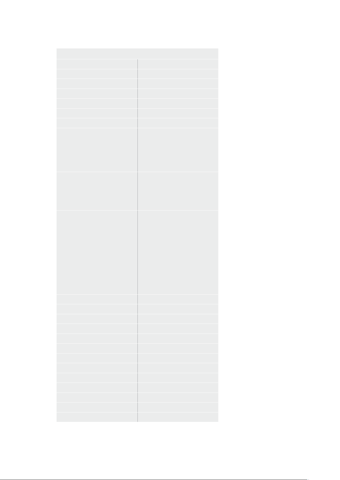
Controls
Filter Median 0/1/2/3/4
Filter Average 0/1/2/3/4
LY In Mix Mode Realistic/Linear/Additive
Backing Color Red/Green/Blue
Cursor Position Default/Last
GP Out Level* High/Low
Output Range Normal/Full
2
Monitor Out Program, FG, BG, Combined
Matte, Internal Matte, Fill, Layer In,
Background Matte In, Garbage Matte
In, Holdout Matte In, Layer Matte
In, Processed LM, Processed HM,
Processed GM, Processed BM, Screen
Correction
Layer Order FG/Layer/BG Layer/BG, Layer/FG/
BG Layer/BG, Layer/BG Layer/FG/BG,
BG Layer/Layer/FG/BG, BG Layer/FG/
Layer/BG, FG/BG Layer/Layer/BG,
FG/BG Layer/BG, BG Layer/FG/BG,
FG/Layer/BG, Layer/FG/BG
Video Format Auto Detect, 525i59.94 NTSC 4:3,
625i50 PAL 4:3, 720p60, 720p59.94,
720p50, 1080i60, 1080i59.94,
1080i50, 1080p60, 1080p59.94,
1080p50, 1080p30, 1080p29.97,
1080p25, 1080p24, 1080p23.98,
1080PsF30, 1080PsF29.97,
1080PsF25, 1080PsF24,
1080PsF23.98, 2160p60, 2160p59.94,
2160p50, 2160p30, 2160p29.97,
2160p25, 2160p24, 2160p23.98,
4320p60, 4320p59.94, 4320p50,
4320p30, 4320p29.97, 4320p25,
4320p24 and 4320p23.98
4
Factory Defaults Yes
5
User Defaults Yes
5
Auto Screen Sample Yes
5
Screen Capture Yes
5
Noise Select Yes
5
Sample Wall Yes
5
Sample Floor Yes
5
Matte Reset Yes
5
Cleanup Reset Yes
5
GM Cleanup Reset Yes
5
FG Color Reset Yes
5
BG Color Reset Yes
5
Flare Reset Yes
5
98Developer Information
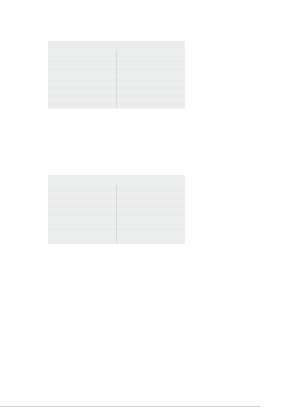
Controls
Ambiance Reset Yes
5
BG Test Signal Color Reset Yes
5
LY Color Reset Yes
5
LY Test Signal Color Reset Yes
5
Window Reset Yes
5
Window Skew Reset Yes
5
GP Out* Yes
5
1 These ranges are Ultimatte device dependent. For Ultimate 12 8K running protocol 2.0, the range is 0-6.
For Ultimatte 12 running version 1.2, the range is 0-3.
2 These controls are only available in protocol version 2.0 and up.
3 Loop outputs for ‘garbage matte’ and ‘holdout matte’ inputs are available for Ultimatte 12, not Ultimatte 12 8K.
4 Supported video formats are Ultimatte device dependent. 4320p formats are available for Ultimatte 12 8K.
Ultimatte 12 HD Mini does not support PsF video formats.
5 These controls represent functions. Send ‘Yes’ to execute the function. Ultimatte will respond with a ‘Yes’
to indicate the function is complete.
* These controls are not available on the Ultimatte 12 HD Mini
** These controls are not available of the Ultimatte 12 HD or HD Mini
Glossary
FG Foreground
BG Background
LY Layer
GM Garbage Matte
BM Background Matte
HM Holdout Matte
LM Layer Matte
99Developer Information

Help
Getting Help
The fastest way to obtain help is to go to the Blackmagic Design online support pages and
check the latest support material available for your Blackmagic Ultimatte or Smart Remote 4.
Blackmagic Design online support pages
The latest manual, software and support notes can be found at the Blackmagic Design support
center at
www.blackmagicdesign.com/support.
Contacting Blackmagic Design support
If you can’t find the help you need in our support material, please use the ‘Send us an email’
button on the support page to email a support request. Alternatively, click on the ‘Find your
local support team’ button on the support page and call your nearest Blackmagic Design
support office.
Checking the version currently installed
To check which version of Blackmagic Ultimatte Setup software is installed on your computer,
launch Blackmagic Ultimatte Setup and click on the ‘about’ tab. The software version number
will be displayed in the ‘software information’ section.
How to get the latest updates
After checking the version of Blackmagic Ultimatte Setup software installed on your computer,
please visit the Blackmagic Design support center at
www.blackmagicdesign.com/support to
check for the latest updates. While it is usually a good idea to run the latest updates, it is a wise
practice to avoid updating any software if you are in the middle of an important project.
100Help
Regulatory Notices and SafetyInformation
Regulatory Notices
Disposal of waste of electrical and electronic equipment within the European union.
The symbol on the product indicates that this equipment must not be disposed of
with other waste materials. In order to dispose of your waste equipment, it must be
handed over to a designated collection point for recycling. The separate collection
and recycling of your waste equipment at the time of disposal will help conserve
natural resources and ensure that it is recycled in a manner that protects human health
and the environment. For more information about where you can drop off your waste
equipment for recycling, please contact your local city recycling office or the dealer
from whom you purchased the product.
This equipment has been tested and found to comply with the limits for a Class A
digital device, pursuant to Part 15 of the FCC rules. These limits are designed to
provide reasonable protection against harmful interference when the equipment is
operated in a commercial environment. This equipment generates, uses, and can
radiate radio frequency energy and if not installed and used in accordance with the
instructions, may cause harmful interference to radio communications. Operation of
this product in a residential area is likely to cause harmful interference, in which case
the user will be required to correct the interference at personal expense.
Operation is subject to the following two conditions:
1 This device may not cause harmful interference.
2 This device must accept any interference received, including interference that may
cause undesired operation.
R-R-BMD-20200824001
R-R-BMD-20211110001
R-R-BMD-20211110002
R-R-BMD-20211110003
MSIP-REM-BMD-201709001
MSIP-REM-BMD-201707003
Safety Information
This equipment must be connected to a mains socket outlet with aprotective
earth connection.
To reduce the risk of electric shock, do not expose this equipment to dripping
or splashing.
This equipment is suitable for use in tropical locations with an ambient temperature
ofup to 40ºC.
Ensure that adequate ventilation is provided around the product and is not restricted.
When rack mounting, ensure the ventilation is not restricted by adjacent equipment.
Onlyuse the designed threaded holes on the base, see Rack Mounting section for details.
No operator serviceable parts inside. Refer servicing to your local Blackmagic Design
service centre.
Use only at altitudes not more than 2000m above sea level.
101Regulatory Notices and SafetyInformation

Warnings for Authorized Service Personnel
Disconnect power from both power inlets before servicing!
Caution - Double Pole/ Neutral Fusing
The power supply contained in this equipment has a fuse in both line
andneutral conductors and is suitable for connection to the IT power
distributionsystemin Norway.
Warranty
12 Month Limited Warranty
Blackmagic Design warrants that this product will be free from defects in materials and workmanship
for a period of 12 months from the date of purchase. If a product proves to be defective during this
warranty period, Blackmagic Design, at its option, either will repair the defective product without
charge for parts and labor, or will provide a replacement in exchange for the defective product.
In order to obtain service under this warranty, you the Customer, must notify Blackmagic Design
of the defect before the expiration of the warranty period and make suitable arrangements for
the performance of service. The Customer shall be responsible for packaging and shipping the
defective product to a designated service center nominated by Blackmagic Design, with shipping
charges pre paid. Customer shall be responsible for paying all shipping charges, insurance, duties,
taxes, and any other charges for products returned to us for any reason.
This warranty shall not apply to any defect, failure or damage caused by improper use or
improper or inadequate maintenance and care. Blackmagic Design shall not be obligated to
furnish service under this warranty: a) to repair damage resulting from attempts by personnel
other than Blackmagic Design representatives to install, repair or service the product,
b) to repair damage resulting from improper use or connection to incompatible equipment,
c) to repair any damage or malfunction caused by the use of non Blackmagic Design parts or
supplies, or d) to service a product that has been modified or integrated with other products
when the effect of such a modification or integration increases the time or difficulty of servicing
the product. THIS WARRANTY IS GIVEN BY BLACKMAGIC DESIGN IN LIEU OF ANY OTHER
WARRANTIES, EXPRESS OR IMPLIED. BLACKMAGIC DESIGN AND ITS VENDORS DISCLAIM
ANY IMPLIED WARRANTIES OF MERCHANTABILITY OR FITNESS FOR A PARTICULAR PURPOSE.
BLACKMAGIC DESIGN’S RESPONSIBILITY TO REPAIR OR REPLACE DEFECTIVE PRODUCTS IS THE
WHOLE AND EXCLUSIVE REMEDY PROVIDED TO THE CUSTOMER FOR ANY INDIRECT, SPECIAL,
INCIDENTAL OR CONSEQUENTIAL DAMAGES IRRESPECTIVE OF WHETHER BLACKMAGIC
DESIGN OR THE VENDOR HAS ADVANCE NOTICE OF THE POSSIBILITY OF SUCH DAMAGES.
BLACKMAGIC DESIGN IS NOT LIABLE FOR ANY ILLEGAL USE OF EQUIPMENT BY CUSTOMER.
BLACKMAGIC IS NOT LIABLE FOR ANY DAMAGES RESULTING FROM USE OF THIS PRODUCT.
USER OPERATES THIS PRODUCT AT OWN RISK.
© Copyright 2022 Blackmagic Design. All rights reserved. ‘Blackmagic Design’, ‘DeckLink’, ‘HDLink’, ‘Workgroup Videohub’,
‘Multibridge Pro’, ‘Multibridge Extreme’, ‘Intensity’ and ‘Leading the creative video revolution’ are registered trademarks in the
US and other countries. All other company and product names may be trade marks of their respective companies with which
they are associated.
Thunderbolt and the Thunderbolt logo are trademarks of Intel Corporation in the U.S. and/or other countries.
102Warranty