User Manual
SPLIT AIR CONDITIONER
Before installing and using your TOSOT Air Conditioner,
please read this user manual in its entirety.
MO DEL NUMBERS
Indoor Unit Outdoor Unit
GWH09AFC-A3DNA2A/I GWH09AFC-A3DNA1A/O
GWH09AFC-D3DNA2A/I GWH09AFC-D3DNA1A/O
GWH12AFC-A3DNA2B/I GWH12AFC-A3DNA1A/O
GWH12AFC-D3DNA2B/I GWH12AFC-D3DNA1A/O
GWH18AFD-D3DNA2A/I GWH18AFD-D3DNA1A/O

Welcome to the TOSOT Direct Family!
We’re extremely happy to welcome you as a new member of our family! Please
read the tips below before using your product for the first time.
1. The split-type air conditioner is a heavy object, which needs two or more people
to lift and install. Failure to do so could result in injury or other accidents.
2. Allow the unit to sit upright for at least 3-4 hours before powering on. Shipping
carriers may set the unit on its side, which causes the refrigerant to pool in
certain areas. Standing the unit upright for 3-4 hours allows the refrigerant to
move freely within the coils.
3. Some parts with sharp edges may cause injury, so gloves are highly
recommended for unpacking and installing.
4. Run the unit continuously for 24 hours after installation. This allows the unit to
work out any “kinks” that may have resulted during shipping from our factory to
your doorstep.
5. If you have any problems with your product, please send us an email before
submitting a return request, as there might be a simple solution for your issue.
Tips for First-Time Use

Table of Contents
------------------------------------------------
--------------------------------------------------------------
------------------------------------------------------------
------------------------------------------------------------
--------------------------------------
------------------------------------
-------------------------------------------
----------------------------------------
-------------------------------------------------------
---------------------------------------
----------------------------------
----------------------------------------
----------------------------------------
-----------------------------------------------------
--------------------------------------------------
----------------------------------------------------
----------------------------------------------------
------------------------------------------------
--------------------------------------
--------------------------------------------
Safety Precautions
Warning
Caution
Electrical Safety Warning
Part List
Required Tools
Parts Description
Remote Control
Function Icons Description
Combination Buttons
Replacing the Batteries
Care and Maintenance
Precautions
Cleaning the Indoor Unit
Cleaning the Reusable Filter
Offseason Maintenance
Preseason Maintenance
Troubleshooting
Malfunction Codes
Quick Guide for Installation
01
01
02
03
04
05
06
07
08
12
13
14
14
14
14
16
16
17
19
20

--------------------------------------
------------------------
-----------------------
--------------------------
---------------------------
------------------------------------------
------------------------------
---------------------------------------
-------------------------------------------
---------------------------------------
-------------
-------------------------------------------
------------------
-----------------------
--------------------------------------------
-----------------------------------------------
------------------------------------------------------
-----------------------------------------
--------------------------------------------
--------------------------------------------------
------------------------------------------
--------------------------------------------------------------
-----------------------------------
Indoor Unit Installation
Select an Installation Site
Attach the Mounting Plate to the Wall
Connect the Wiring of the Indoor Unit
Connecting the Refrigerant Pipings
Drilling the piping hole on the wall
Mount the Indoor Unit
Extend the pipe by unwinding it
Outdoor Unit Installation
Select a Installation Site
Install the Drain Joint
Secure the Outdoor Unit
Connect the Refrigerant Pipe to Outdoor Unit
Note On Pipe Length
Refrigerant Piping Connection Instructions
Connect the Signal and Power Cables
Air Evacuation
Gas Leak Checks
Electrical Safety Checks
Test Run
Warranty & Customer Support
Warranty Information
Customer Support
25
25
26
26
28
31
32
33
34
34
35
35
36
37
37
40
42
43
43
44
45
45
45

Safety Precautions
01
Your safety and the safety of others are very important to us. Please read the
following safety precautions before use and installation. A digital version can be
obtained from customer support.
Warning
Failed to do the following instructions might cause the possibility of death or
serious injury.
1. Do not connect the power before finishing installation.
2. Do not spray or wash the air conditioner with water to avoid electric shock or
malfunction.
3. Do not insert fingers or objects into the air inlet or air outlet. It may cause
personal injury or damage.
4. Do not block the air outlet or air inlet. It may cause malfunction.
5. Installation must be performed according to installation instructions and in
accordance with the requirement of NEC and CEC by authorized personnel only.
Improper installation may cause water leakage, electrical shock, fire, or may
void the warranty.
6. Service or maintenance must be performed by authorized and qualified
professionals. Otherwise, it may cause serious damage or personal injury or death.
7. Make sure the power supply is cut off before proceeding with any work related
to electricity or general maintenance.
8. If the refrigerant leaks or requires discharge during installation, maintenance,
or disassembly, it should be handled by certified professionals or otherwise in
compliance with local laws and regulations.
9. The air conditioner must be properly grounded. The grounding resistance should
comply with national electric safety regulations. Incorrect grounding may cause
electric shock.
10. This appliance is not intended for use by persons (including children) with
reduced physical, sensory or mental capabilities or lack of experience and
knowledge, unless they have been given supervision or instruction concerning
use of the appliance by a person responsible for their safety.

02
Caution
1. Please follow the instructions for installation and use of this product in this user
manual.
2. The indoor unit should be installed close to the wall.
3. The appliance must be positioned so that the plug is accessible. The plug should
be able to reach a properly-grounded wall outlet after finishing installation.
Extension cords, power strips, or similar devices should not be used with this
product.
4. The yellow-green wire in the air conditioner is grounding wire, which cannot be
used for other purposes.
5. The temperature of the refrigerant circuit will be hot. Please keep wires and
cables away from the copper refrigerant tube.
6. Do not spill water on the remote controller, otherwise the remote controller may
be broken.
7. Do not use a hair dryer to dry the filter after washing to avoid deformation or fire
hazard.
8. Do not step or put heavy objects on the top panel of the outdoor unit. It may
cause damage or personal injury.
9. If any of the below issues occur, please turn off the air conditioner and disconnect
power immediately. Contact the dealer or qualified professionals for service.
a. Power cord is overheating or damaged.
b. There are abnormal sounds during operation.
c. Circuit breakers trips frequently.
d. Air conditioner gives off a burning smell.
e. Indoor unit is leaking.
11. This appliance can be used by children ages 8 and above and persons with
reduced physical, sensory or mental capabilities, or lack of experience and
knowledge, if they have been given supervision or instruction concerning use
of the appliance in a safe way and understand the hazards involved. Children
shall not play with the appliance. Cleaning and user maintenance shall not be
made by children without supervision.
12. After removing the filter, do not touch the metal fins in order to avoid injury.

03
Electrical Safety Warning
1. Do not share the same electrical socket with other appliances as this may create
a fire hazard.
2. Do not cover the power cord with a rug or carpeting.
3. Do not rest hot or heavy objects on the appliance and power cord.
4. Never plug or unplug the appliance with wet hands.
5. Never unplug the appliance by pulling on the power cord.
6. According to the local safety regulations, use a qualified power supply circuit and
circuit breaker and make sure the power supply matches with the requirement of
the air conditioner. Unstable power supply may result in electric shock, fire hazard
or malfunction.
7. All wires of indoor unit and outdoor unit should be in accordance with national
wiring regulations.
8. If the power cord is damaged, it must be replaced by the manufacturer or an
authorized technical service center.
9. Make sure the power supply is cut off when cleaning the air conditioner.
Otherwise, it may cause electric shock.
04
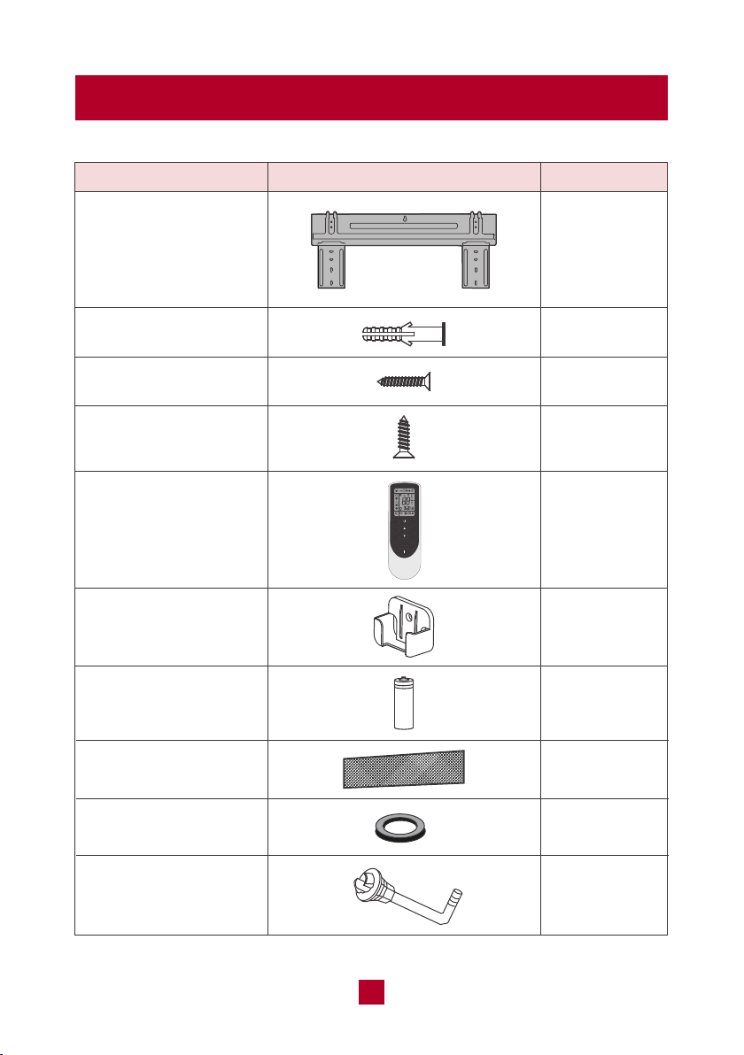
Parts List
Mounting plate
Drywall anchor
Remote control holder
AAA battery
Air filter
Wall cuff
Drain joint
Mounting plate fixing
screw
PART
LOOKS LIKE
QUANTITY
1
1
1
1
1
Fixing screw for remote
controller holder
2
2
5
5
Remote control 1
MODE
FAN
SWING
TURBO
SLEEP TEMP
WiFi
LIGHT
CLOCK
TIMER
ON
TIMER
OFF

05
Required Tools
Pipe bundle (5 meters)
Electrical cables
(6 meters)
Sealing gum
Tape
Drain hose (2 meters)
PART
LOOKS LIKE
QUANTITY
1
1
1
2
1
1. Bubble Level
2. Electric Drill with drill bit for pilot holes
3. Wire stripper/crimp tool
4. Screwdriver
5. Standard wrench
6. Open-end torque wrench
7. Drill with 2.2/2.8 inch hole saw
8. Vacuum pump
06
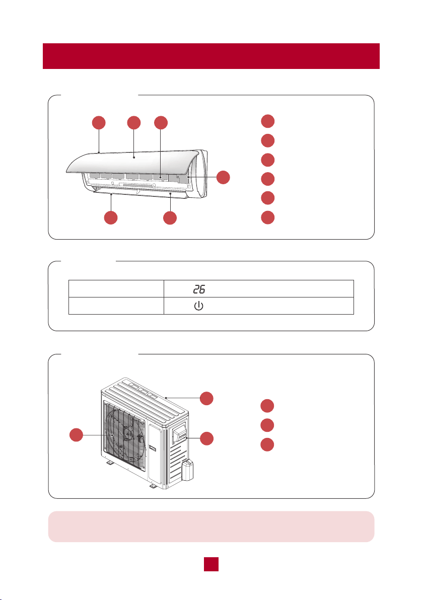
Parts Description
Indoor Unit
Display
1
2
3
4
5
6
Air Inlet
Front Panel
Reusable Filter
Air Outlet
Horizontal Louver
Aux Button
1 2 3
5
4
6
Indoor Unit
1
1
2
3
Air Inlet
Wire Connection
Air Outlet
Temp Indicator
Power Indicator
Note: This is a universal introduction for a variety of models. Display
content may be different from the actual. Please refer to the actual unit
2
3
07
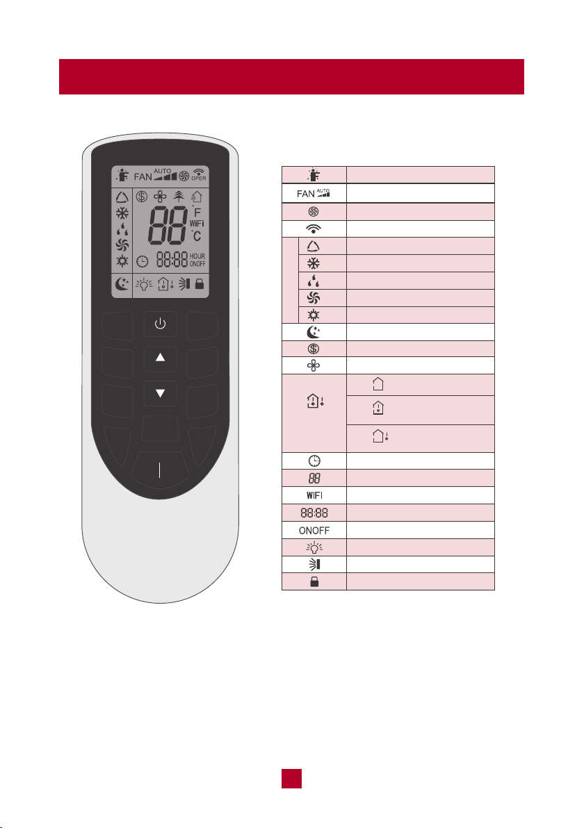
Remote Control
Temperature Setting
Sleep Mode
Freeze Guard Function
X-FAN Function
WiFi Function
Light
Set Temp.
Outdoor Ambient
Temp.
Indoor Ambient
Temp.
Clock
Time Setting
Timer On/Off
Up & Down Swing
Turbo Mode
Send Signal
Auto Mode
Cool Mode
Child Lock
Operation Mode
Dry Mode
Fan Mode
Heat Mode
I Feel
Fan Speed Setting
Temp.
Display Type
MODE
FAN
SWING
TURBO
SLEEP
TEMP
WiFi
LIGHT
CLOCK
TIMER
ON
TIMER
OFF
Function icons:
Note:
● This is a universal remote control for a variety of different models. If your model
does not have a function listed on the remote control, when you press the
corresponding button on the remote controller, the unit will keep the original
setting and there will be no changes in the operation of your unit.
● Outdoor Ambient Temp. is not available for this model.
08
Function Icons Description
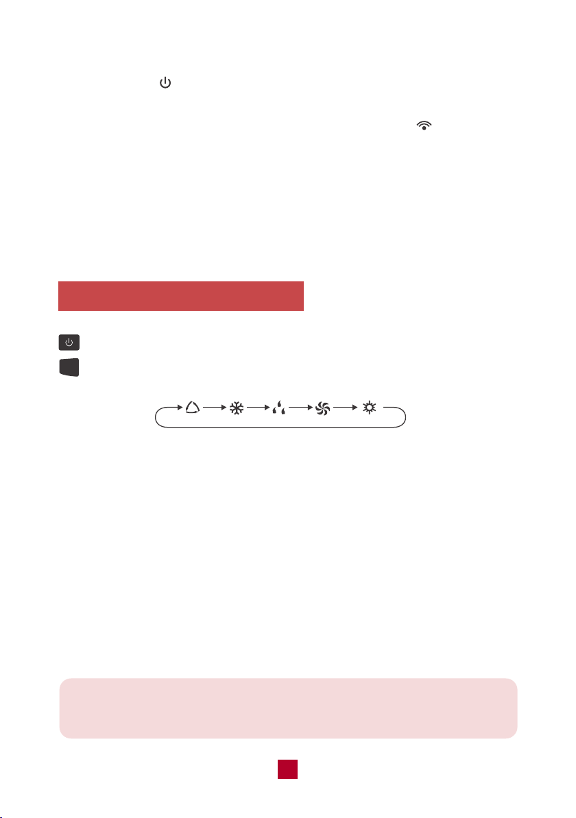
Press this button to turn on the unit. Press this button again to turn off the unit.
Press this button to cycle through the following modes:
Note: After starting up the heat mode, the indoor unit will delay 1~5 minutes
before it starts blowing air. The actual delay time will depend on the current
indoor temperature.
MODE
● Once the unit is powered on the air conditioner will give out a sound and the
power indicator will light up. After that you can operate the air conditioner
by using remote control.
● When pressing a button on the remote control, the signal icon on the remote
control will blink once and the air conditioner will emit a single beep sound, which
means the signal has been sent to the air conditioner. The remote control will
display the active function icons.
● While powered off the set temperature and clock icons will be displayed. If the
timer or light functions are set, the corresponding icons will be also displayed on
the remote control.
AUTO COOL DRY FAN
HEAT
Auto mode: The air conditioner will adjust the fan speed automatically to maintain
the set temperature. The set temperature can't be adjusted. Press "FAN" button
can adjust fan speed.
Cool mode: The air conditioner will operate under standard cooling mode. The set
temperature and fan speed can be adjusted.
Dry mode: The air conditioner will run on low speed for dehumidification. The fan
speed cannot be adjusted.
Fan mode: The air conditioner will not produce cool or warm air, only blow air from
the current room temperature. The fan speed can be adjusted.
Heat mode: The air conditioner operates under heat mode instead of cooling. The
set temperature and fan speed can be adjusted.
09
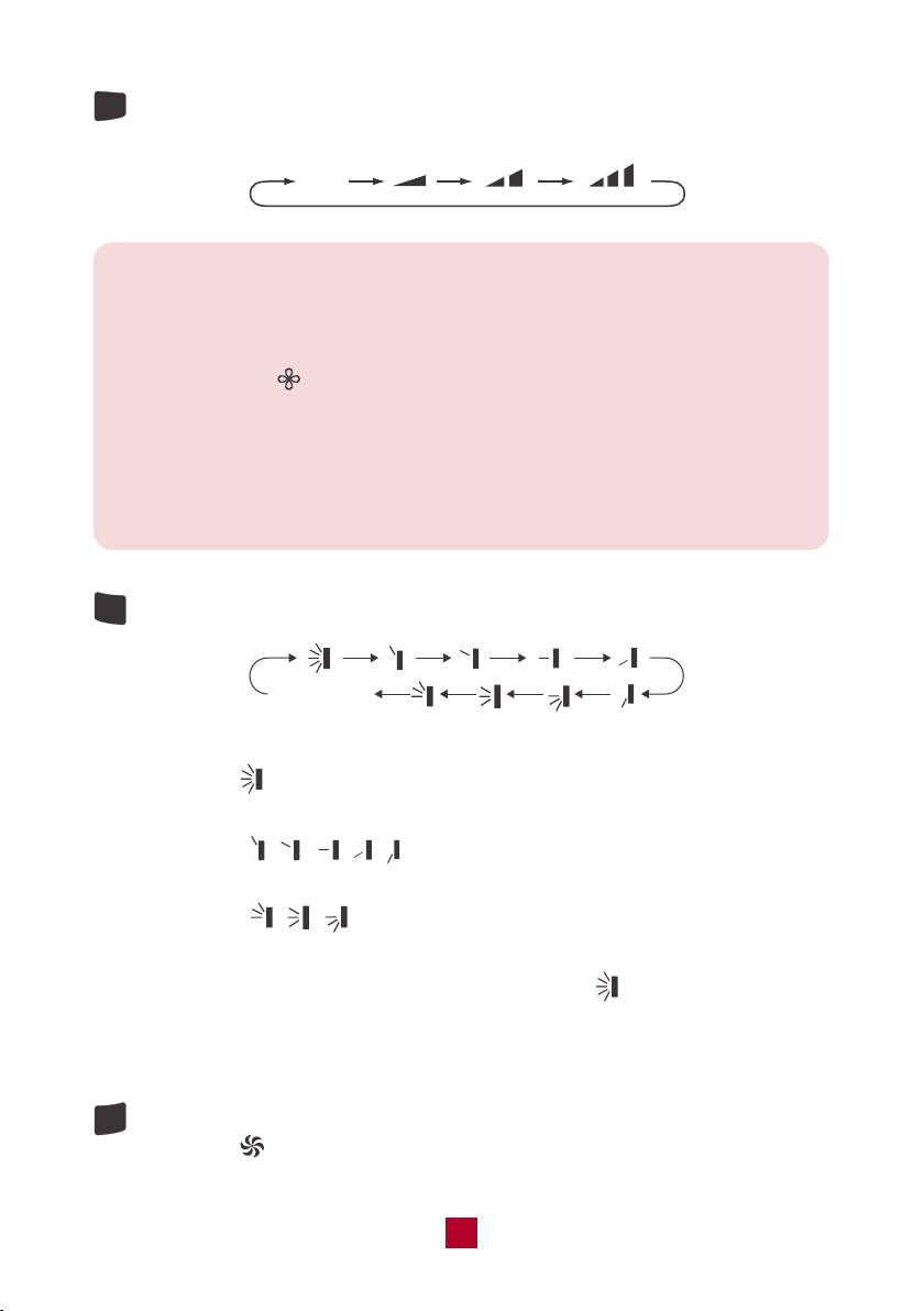
Press this button to cycle through the Auto fan mode and 3 fan speeds (Low,
Medium, High)
FAN
SWING
TURBO
Auto
Note:
● Under AUTO fan mode, the air conditioner will select the proper fan speed
automatically.
● X-FAN Function:Hold the fan speed button for 2 seconds in COOL or DRY
mode. The icon will be displayed. Under this mode the indoor fan will
continue operating for a few minutes after powering off in order to dry the
indoor unit. X-FAN is not available in AUTO, FAN or HEAT modes. This
function will help to dry the moisture on the evaporator to prevent mold.
To shut the X-FAN off after powering the unit off, hold the fan speed button
for 2 seconds.
Press this button to cycle through the following air flow directions:
no display
(horizontal louvers
stops at current position)
When selecting , the horizontal louvers will automatically swing up & down
across the maximum range. .
When selecting " ", the unit will blow air at a fixed position.
The horizontal louvers will not move.
When selecting " ", the unit will blow air across a set range.
The louvers will automatically swing up & down across this range.
To manually set a fixed air direction, press and hold the " button for 2 seconds
until it reaches your desired angle, then release the button. The louvers will not
move from this position.
Under cool or heat modes, press this button to enter quick cool or quick heat
mode. The icon will display on the remote control. Press the button again
to exit the turbo function and the icon will disappear.
10
SLEEP
● Pressing the ▲ or ▼ button will increase/decrease the set temperature by
1°F. Holding the button for 2 seconds will cause the temperature to change
rapidly. Release the button once your desired temperature is reached.
● After pressing the Timer or Clock button, press the ▲ or ▼ button to adjust
the time.
● Under cool or heat mode,press this button to enter the sleep operation
mode. The icon will display on remote control. Press the button again to
exit sleep mode. Sleep mode is only available in cooling or heating modes,
as explained in detail below.
● During sleep, the set temperature of the air conditioner may no longer be
suitable to the human body’s optimal sleeping needs. By activating the
sleep function with the remote control, the air conditioner will automatically
adjust the set temperature to meet the optimal sleeping needs of the human
body.
Sleep Mode Under Cooling Mode
1. If the temp is set to 61-74°F (16-23°C), the temp will increase 2°F per hour
for 3 hours. Four (4) hours later the temp will decrease by 2°F and remain
at this temp.
2. If the temp is set to 75-81°F (24-27°C), the temp will increase 2°F per hour
for 2 hours. Five (5) hours later the temp will decrease by 2°F and remain
at this temp.
3. If the temp is set to 82-84°F (28-29°C), the temp will increase 2°F per hour
for 1 hour. Six (6) hours later the temp will decrease by 2°F and remain at
this temp.
4. If the temp is set to 85°F (30°C), the temp will not increase. Seven (7) hours
later the temp will decrease by 2°F and remain at this temp.
Sleep Mode Under Heating Mode
1. If the temp is set to 61°F (16°C), it will run at this temp with no change.
2. If the temp is set to 62-68°F (17-20°C), the temp will decrease 2°F per hour
for 1 hour and remain at this temp.
3. If the temp is set to 69-81°F (21-27°C), the temp will decrease 2°F per hour
for 2 hours and remain at this temp.
4. If the temp is set to 82-86°F (28-30°C), the temp will decrease 2°F per hour
for 3 hours and remain at this temp.
11
TEMP
LIGHT
CLOCK
TIMER
ON
TIMER
OFF
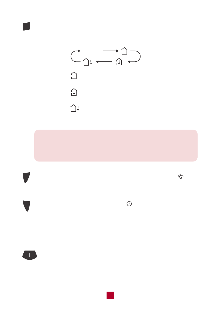
Press this button, you can see indoor set temperature, indoor ambient
temperature or outdoor ambient temperature on the indoor unit's display.
The setting on remote control will cycle through as below:
no display
When selecting " " or no display with the remote control, the temperature
indicator on the indoor unit displays the set temperature.
When selecting " " with the remote control, the temperature indicator on
the indoor unit displays the indoor ambient temperature.
When selecting " " with the remote control, the temperature indicator on
the indoor unit displays the outdoor ambient temperature. ● Not available for
this model.
Note: (This function might vary across different models)
When selecting the display of indoor or outdoor ambient temperature,
the temperature indicator displays the corresponding temperature then
automatically turns to display the set temperature after a few seconds.
Press this button to turn off the display light on the indoor unit. The icon
on the remote control will disappear. Press the button again to turn on the
display light.
Press this button to set the clock time. The icon on the remote control will
blink. Press the "▲" or "▼" button within 5 seconds to set clock time. Each
press of the "▲" or "▼" button will increase or decrease 1 minute. Holding
the "▲" or "▼" button will change time rapidly. Release this button after
reaching your required time. Press the "CLOCK" button again to confirm the
time and the icon will stop blinking.
TIMER ON/OFF:
When the unit is not running, press this button to schedule when the unit
will power on by using the "▲" or "▼" button to adjust the length of time
before powering on.When the unit is running, press this button to schedule
when the unit will power off. The timer setting will increase or decrease by

12
Combination Buttons
● Energy-Saving Mode
Under cool mode, press and hold the TEMP and CLOCK buttons simultaneously
to activate or turn off the energy-saving function. When the energy-saving function
is activated, "SE" will be displayed on the remote control and the air conditioner
will adjust the set temperature automatically to save on energy costs.
Under Energy-saving Mode the fan speed and temperature settings can’t be
adjusted and the TURBO mode is not available. Sleep mode and Energy-Saving
Mode can’t operate at the same time.
● Freeze Guard Heating Function
Under heat mode, press and hold the TEMP and CLOCK buttons simultaneously
to activate or turn off the freeze guard function. When this function is activated,
and "46°F/8°C" will be shown on remote control, and the air conditioner keeps
the room temperature above 46°F/8°C.
Under the Freeze Guard Heating Function, fan speed and temperature settings
can’t be adjusted and the "TURBO" mode is not available. The sleep mode and
the Freeze Guard Heating Function can’t operate at the same time.
This function is typically used when away for vacation or holiday and is intended
to save energy and protect pipes or plants from freezing when the building is
unoccupied.
1 minute with each press of the "▲" or "▼" button. Holding the "▲" or "▼"
button for 2 seconds will change the time rapidly. Release the button once
it reaches your set time. . Press the button again to confirm the timer and
the "ON"/"OFF" indicator on the remote control will stop blinking.
Note: " " button takes no effect on the timer setting. If you don’ t
need the timer, press the TIMER ON/OFF button to cancel and the
timer indicator light will shut off.
13
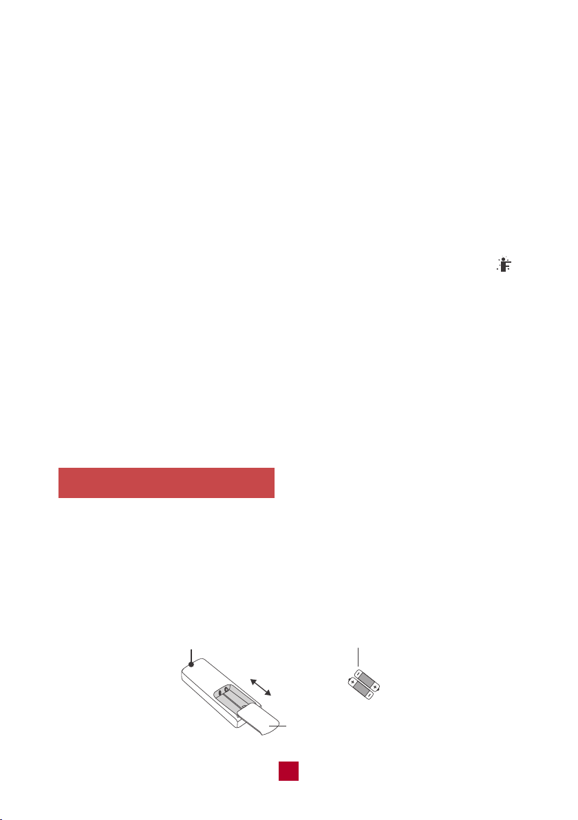
Replacing the Batteries
● Child lock
Press ▲ and ▼ simultaneously to turn the child lock function on or off. While in
this mode the remote control will display a LOCK symbol and will not send any
signal to the air conditioner.
● Change Between °F and °C
With the unit powered off, press the MODE and ▼ buttons simultaneously to switch
between Fahrenheit and Celsius displays.
● I FEEL
Press the ▲ and MODE buttons simultaneously to activate I FEEL mode. The
icon will be displayed on the remote control. In this mode your unit will use a
sensor located in the remote control to determine the temperature setting of your
air conditioner.
Please put the remote control near the user when using this function. Do not put
the remote control near any place with too high or too low temperature in order to
avoid inaccurate temperature readings. When I FEEL is turned on, the remote
control should be put within 20 ft of the indoor unit so the unit can receive the
signal from the remote control.
● Press the back side of the remote control battery cover and slide out following
the engraved arrow.
● Replace with two new AAA(1.5V) batteries of the same make and model. Make
sure the polarities (+ & -) are aligned correctly.
● Reinstall the battery cover box.
Signal Sender
Battery
Reinstall
Remove
Cover of Battery Box
14
Care and Maintenance
Precautions
● Disconnect from power before cleaning and servicing. Failure to do so may
cause electric shock.
● Do not wash the air conditioner with water as this may cause electric shock.
● Do not use volatile liquids (such as paint thinner or gas) to clean the air
conditioner. This may damage the appearance of the air conditioner or cause
parts to deteriorate.
● Do not use liquid or corrosive detergent to clean the appliance and do not
splash water or other liquid onto it as this may damage plastic components
or cause electric shock.
Cleaning the Indoor Unit
If there's dust on the surface of the outer case please use a soft cloth to wipe it
clean. You might need to use mild detergent for cleaning.
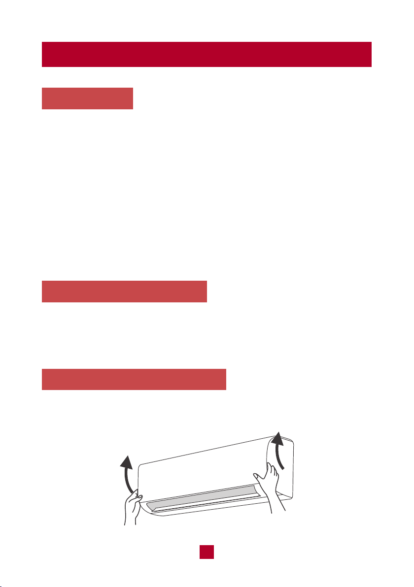
Cleaning the Reusable Filter
1. Lift the front panel up towards the ceiling.
15
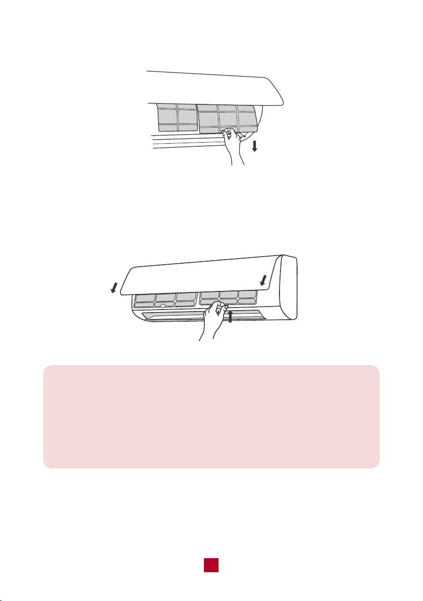
2. Remove the filter by pulling it downward.
3. Clean the filter with warm water mixed with a mild detergent. A soft bristle brush
may help remove some dirt if needed. Dry completely in a cool area.
4. After the filter has dried, reinstall back into the air conditioner and close the front
panel tightly.
Note:
● Clean the filter at least once per month.
● Do not touch the metal fins in the air conditioner after removing the filter as
they may cause injury.
● Do not attempt to dry the filter with a hairdryer or other heating elements as
this may deform or ignite the filter.
● Do not operate the air conditioner if the air filter is missing.

16
Offseason Maintenance
If you are going to put the unit into long-term storage, please do the following:
1. Disconnect from power supply.
2. Clean filter and outer case.
3. Remove dust and debris on the air conditioner.
4. Turn on the FAN mode for at least 8 hours to dry the indoor unit out completely.
Preseason Maintenance
If you are going to use the unit again after a long period of non-use, please
do the following:
1. Check whether air inlets and air outlets are blocked.
2. Check whether plug and socket are in good condition.
3. Check whether the filter is clean.
4. Check whether batteries are installed in the remote control.
5. Check whether the unit is leaking any refrigerant or water.
17
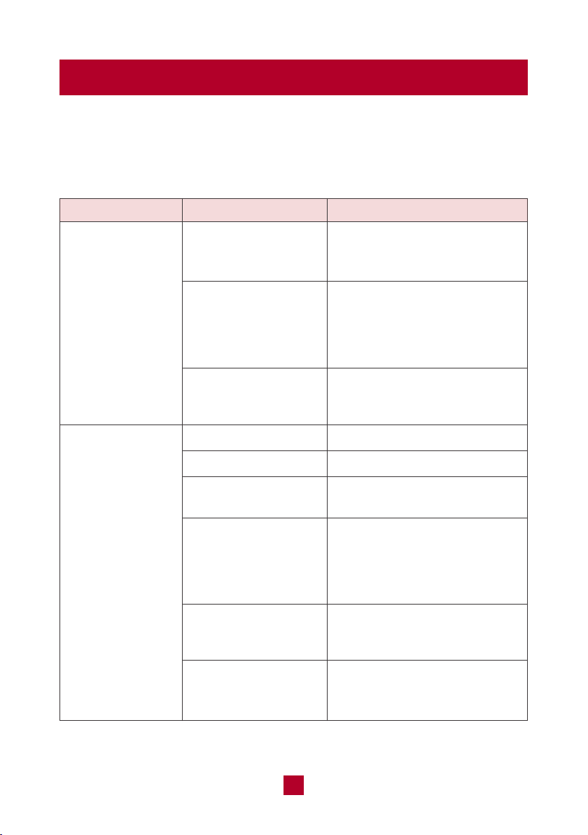
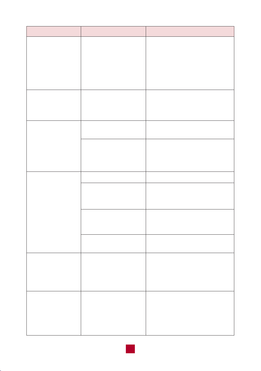
Troubleshooting
You may meet some common issues listed below. We recommend you do a
self check first, but if the problem is not resolved, please contact customer
support at [email protected].
Is the air inlet or
outlet of the indoor
unit blocked?
If using the heating
and cooling mode,
has the indoor
temperature reached
the set temperature?
Did you just turn the
heating mode on?
Power failure?
Is the plug loose?
Circuit breaker trips
or fuse blown?
Did you just restart
the unit after powering
it off?
Are batteries in the
remote control
exhausted?
Are batteries in the
remote control installed
properly?
Remove the obstacles.
Once the ambient indoor
temperature reaches the set
temperature, the indoor unit
will stop blowing out air.
After starting the heat mode the
indoor unit will delay 1-5 minutes
before blowing air.
Wait after power recovery.
Reinsert the plug.
Contact customer support or
qualified professionals.
The unit is experiencing the
3-Minute Compressor Protection
to help extend the lifespan of
your unit. Wait for 3min, and
then turn on the unit again.
Replace with two new AAA(1.5V)
batteries.
Make sure the polarities (+ & -)
are aligned correctly.
No air emitted from
the indoor unit
Air conditioner will
not operate
Issues Self check Solutions
18
Issues Self check Solutions
In humid regions, a large
temperature difference between
the room’s air and the conditioned
air can cause white mist. After a
while, indoor temperature and
humidity will decrease and the
mist will disappear.
Remove the odour source and
clean the reusable filter.
Temperature can’t be adjusted
under auto mode.
Temperature setting range:
61°F(16°C) - 86°F(30°C).
Clean the air filter.
Adjust the temperature setting
and mode.
Close windows and curtains
during periods of high heat or
bright sunshine.
Make sure all doors and
windows are closed.
Disconnect power, wait
30 seconds and restart, then
turn on the unit again.
Low hissing sound when the
system starts, has just stopped
running, or is defrosting. This
noise is normal and is caused
by the refrigerant gas stopping
or changing direction.
Are the indoor
temperature or
humidity levels high?
Check whether there’s
odour source such as
new furniture or
smoking, etc.
Unit is running under
auto mode?
Your desired
temperature exceeds
the set temperature
range?
Is the air filter dirty?
Are the temperature
and mode settings
proper?
Is direct or strong
sunlight shining into
the room during cooling?
Are doors and windows
open to the room?
Check if there’s
interference such as
cell phone towers,
thunder, wireless
devices, etc.
Air conditioner was just
turned on or turned off?
White mist emitted
from indoor unit
Strange odours
emitted
Set temperature
can’t be adjusted
Poor cooling
or heating
performance
Operation is
unstable and
abnormal
Abnormal noises

19
Malfunction Codes
Issues Self check Solutions
Cracking sound: Normal
expansion and contraction of
plastic and metal parts caused
by temperature changes during
operation.
Air conditioner was
just turned on or
turned off or adjusted
temperature?
Abnormal noises
Error Code Malfunction Name
● If you notice or experience any of the following conditions, please turn off the air
conditioner, disconnect from power, discontinue use, and contact support
immediately.
○ The power cord is overheating or otherwise damaged
○ Abnormal sound during operation
○ A strange odor is emitted from the unit
○ Excessive water leakage the unit
● Do not attempt to repair or retrofit the air conditioner by yourself. All repairs
must be performed by qualified individuals.
F0
F1, F2, F4
H3, E8
E2
E5
E6
H6
P5, H5
PL
Refrigerant leakage protection
Temperature sensor malfunction
Overload protection
Antifreezing protection
Overcurrent protection
Communication malfunction
Internal fan motor do not operate
IPM protection
Voltage of DC bus-bar is too low
Refill the refrigerant.
Remove the unit from power for a few minutes.
Plug the unit back in to determine if the
malfunction code is still present.
1. Check and make sure the supply voltage is
stable and consistent with the rated range.
2. Check if the inlet/outlet is blocked, remove the
blockage.
Reconnect the line according to wiring diagram.
After powerring off, turn the fan blades by hand
to ensure the blades are running smoothly.
1. Check if the filter or the inlet/outlet is
blocked, remove the blockage.
2. The temperature sensor or the mainboard
is broken.
Measure the voltage of position L and N on wiring
board, if the voltage is higher than 150V, turn on
the unit after the supply voltage is increased to the
normal range.
Solutions
20
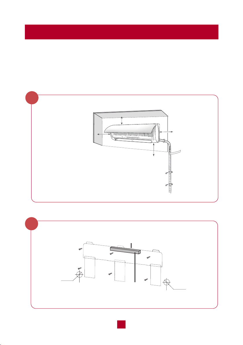
Quick Guide for Installation
These are basic instructions to help you quickly set up your unit. For a more
detailed explanation, please read the Indoor Unit Installation (page 25) and
Outdoor Unit Installation (page 34):
Indoor Unit:
Select an Installation Site
At least 15cm
At least 15cm
At least 250cm
At least
15cm
Attach the Mounting Plate to the Wall
Φ55m
Φ70mm
Φ55m
Φ70mm
Rear piping hole
Rear piping hole
Bubble level
1
2
● If placed under 250cm, the cooling effect of
the air conditioner cannot be fully utilized.
21
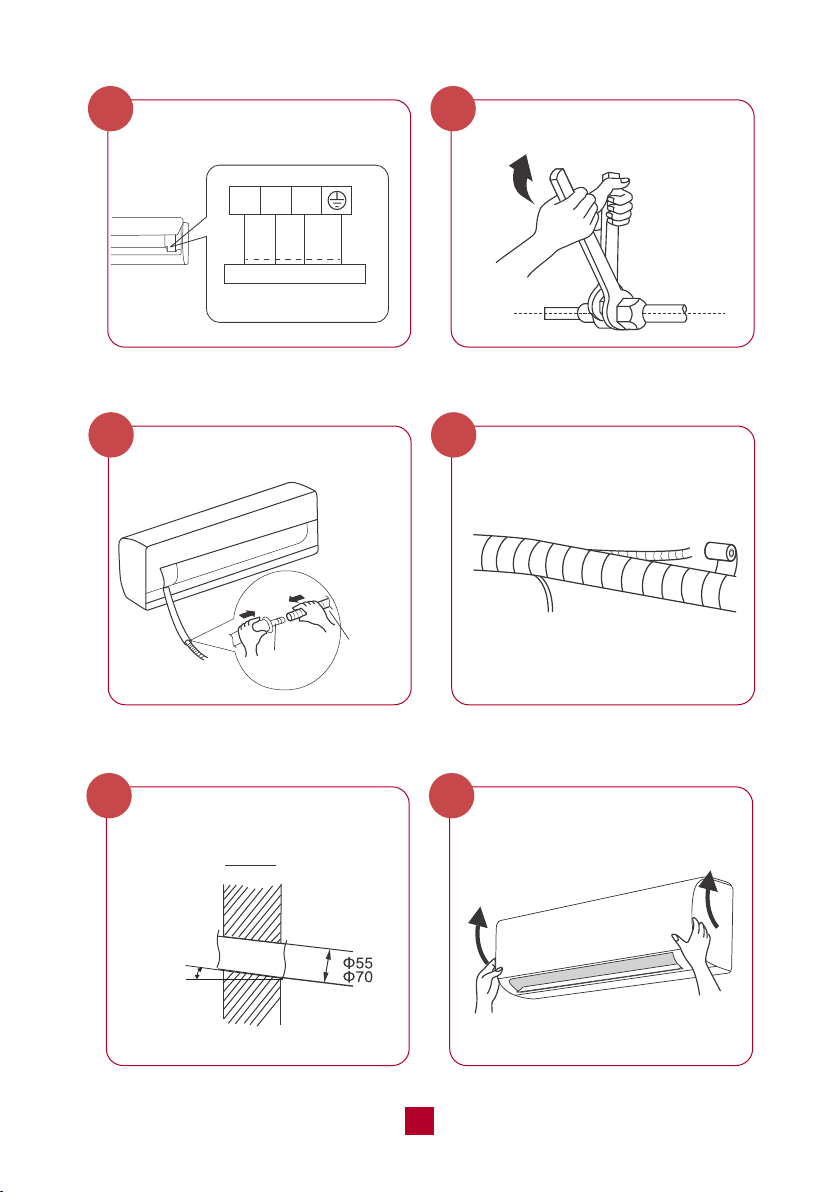
black
N(1) 2 3
Outdoor unit connection
green
(yellow-
green)
white
(blue)
red
(brown)
outlet pipe
drain hose
Connect the Piping
4
Connect the Wiring
3
Wrap the Pipping
6
Connect the Drain Hose
5
Mount the Indoor Unit
8
Drill Wall Hole
7
Indoor outdoor
5-10°
22
Select a Installation Site
1
Secure the Remote Control
Holder
9
Outdoor Unit:
minimum 19.7in (50 cm)
minimum 78.7in (200 cm)
minimum 19.7in (50 cm)
minimum 11.8 in (30 cm)
minimum
11.8 in (30 cm)
23
Install the Drain Joint
2
Connect the Refrigerant Pipe
4
Secure the Outdoor Unit
3
chassis
drain joint
Drain hose
Connect the Signal and Power Cables
5
foot holes
foot holes
lock nut
Finish
conduit
24
Air Evacuation
6
Electrical Safety Checks
8
Gas Leak Checks
7
25
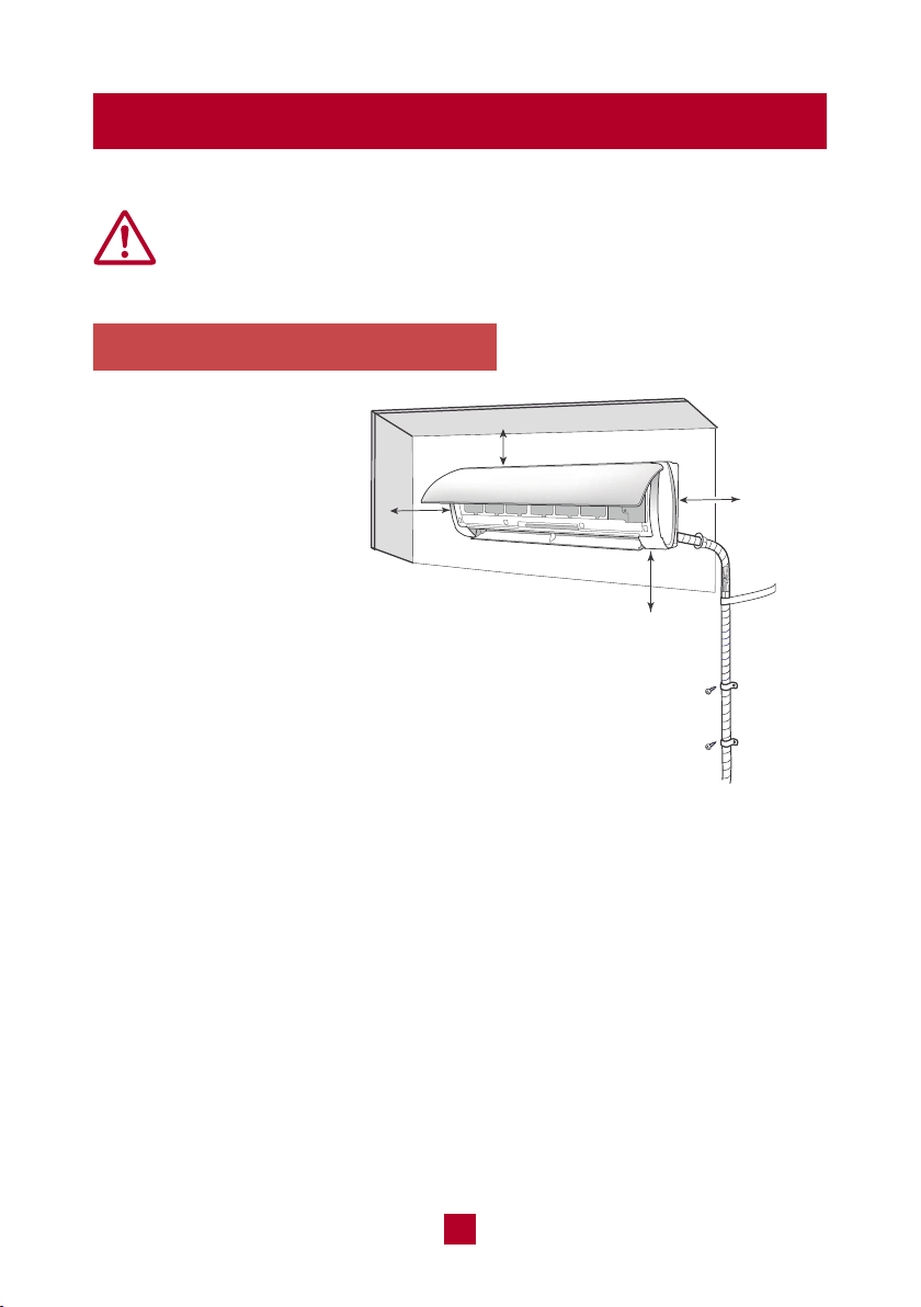
Indoor Unit Installation
1. Select an Installation Site
Refer to the following
diagram to ensure proper
distance from walls and
ceiling:
Minimum 6 in (15 cm)
Minimum
6 in (15 cm)
Minimum 98.5 in (250cm)
Minimum
6 in (15 cm)
Before installing the indoor unit, you need to check the label on the
product box and make sure that the model number of the indoor unit
matches the model number of the outdoor unit.
An appropriate install location should follow
these standards:
● Convenient drainage for water condensation.
● Convenient to connect the outdoor unit
● Near a properly-grounded wall outlet
● Not easily accessible for children.
● Strong enough to support the weight of the unit.
● Away from other electric appliances (e.g. TV, radio, computer, etc.)
● Not near fluorescent lamps.
DO NOT install the unit in the following locations:
● Near strong heat sources or where vapors, flammable or explosive gas,
or volatile objects can be spread in the air.
● Near high-frequency devices such as welding machines or medical equipment.
● Corrosive environments such as the laundry room or swimming pool.
● Any filled with oil, sulfurated gas or fumes in the air.
● If placed under 250cm, the cooling
effect of the air conditioner cannot
be fully utilized.
26
Notice: All wiring of the indoor and outdoor units should be completed by a
professional electrician or HVAC installer.
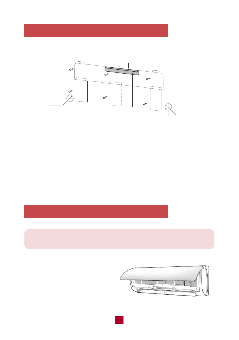
2. Attach the Mounting Plate to the Wall
3. Connect the Wiring of the Indoor Unit
Φ55m
Φ70mm
Φ55m
Φ70mm
Rear piping hole
Rear piping hole
Bubble level
The mounting plate is where you will mount the indoor unit.
● Hold the mounting plate against the wall and adjust the plate using a bubble
level until perfectly level.
● Mark screw holes on the wall and drill pilot holes with a drill. You may need a
stud finder to find wooden studs to securely anchor the mounting plate. Do not
just drill holes through drywall as this is not strong enough to support the indoor
unit.
● Secure the mounting plate to the wall with the provided screws until the mounting
plate is firmly attached to the wall.
front panel
screw
wiring cover
● Open the front panel of the indoor
unit and use a screwdriver to pry
open the wiring cover located on
the right side. This will reveal the
terminal block.
27
● Using wire strippers, remove the rubber insulation from both ends of the signal
cable in the lineet to reveal approx. 6 inches (15cm) of wiring.
● Using a crimp tool, crimp U-Type lugs (not included) on both ends of the wires.
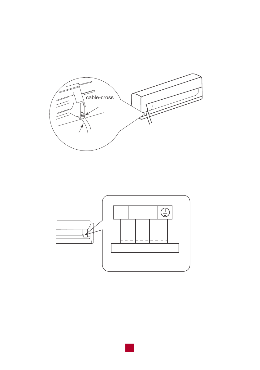
● Feed the power connection wire from the rear right of the unit though the cable
cross hole and pull it through from the front of the unit.
hole
power connection
wire
● Match the colored wires to the correct labels on the terminal block. Connect the
power connection wire and firmly screw each wire to its corresponding terminal.
black
N(1) 2 3
Indoor unit connection
green
(yellow-
green)
white
(blue)
red
(brown)
● After ensuring that each connection is secure, tightly screw down the cable clamp.
● Snap the wiring cover back into place and shut the front panel.
NOTE: Make sure the connection is following the instruction.
28
NOTE: If the union nut is too loose it will cause leaks. Over-tightening may
damage connections and cause leaks. Carefully tighten the union nut to the
correct torque level referring to the Torque Table below. If you need help on
this step, please contact customer support.
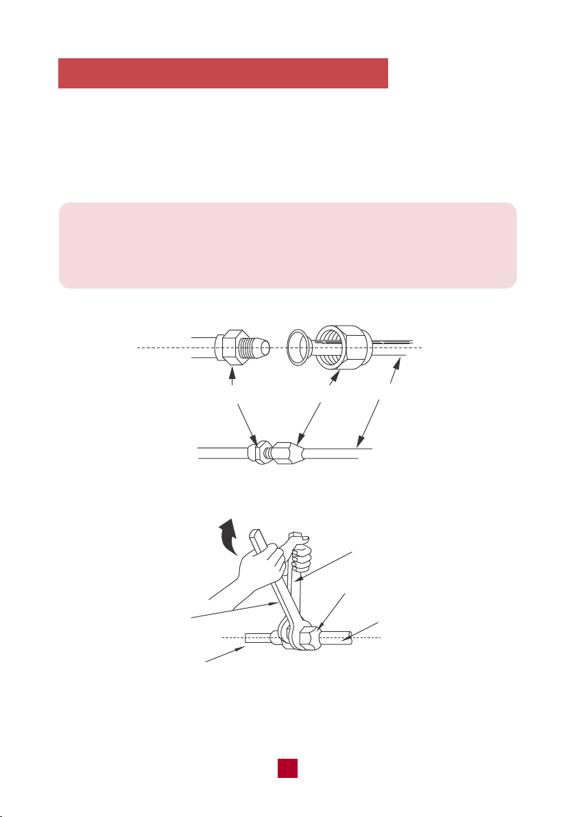
4. Connecting the Refrigerant Pipings
● Align both ends of the refrigerant pipings and start to twist on the union nut by
hand.
● Use a standard wrench on the pipe joint and an open-end torque wrench on the
union nut to apply the proper torque as shown in the torque table below.
pipe joint
pipe
union nut
open-end torque wrench
pipe
indoor pipe
standard
wrench
union nut
29
Pipe Diameter Nut Size
1/4 (6)
3/8 (9.5)
1/2 (12.7)
5/8 (16)
Torque Table
Tightening Torque
inch (mm)inch (mm) ft-lbs N-m
1/4 (17)
3/8 (22)
1/2 (25)
5/8 (29)
10 to 13
25 to 30
36 to 45
50 to 60
15 to 20
30 to 40
45 to 55
60 to 65
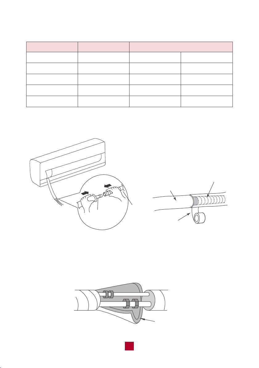
● Connect the drain hose to the outlet pipe of the indoor unit and secure the joint
with tape.
outlet pipe
drain
hose
drain hose
outlet pipe
tape
● Wrap the joints with the included insulating material to prevent condensation.
insulating pipe

30
Note: When wrapping the bundle, keep the ends of the piping unwrapped.
You need to access them to test for leaks at the end of the installation process.
● Wrap the refrigerant pipes, electrical cables, and drain hose with tape so it looks
like the below figure
indoor unit
tape
drain hose
electrical cables
● Reserve a few inches of drain hose and power cable. When wrapping to a
certain length, separate the indoor power cord and then separate the drain hose.
refrigerant
pipes
connection pipe
drain hose
Tape
indoor power cord
31
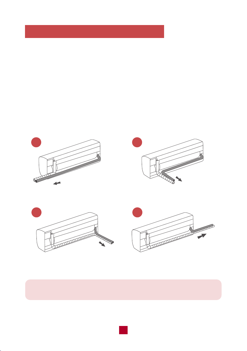
Be extremely careful not to dent or damage the piping while bending them
away from the unit. Any dents in the piping will affect the unit’s performance.
1 2
3 4
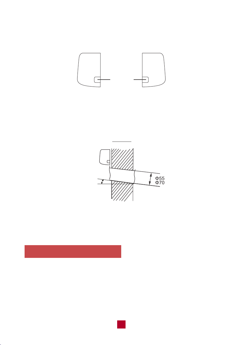
5. Drilling the piping hole on the wall
You must drill a hole in the wall for the wrapped bundle of pipes to connect the
indoor and outdoor units.
● Choose an appropriate location for the piping hole based on the position of the
mounting plate and the direction of the pipe. There are four directions you could
choose:
1. Out of the right side of the indoor unit
2. Out of the rear right side of the indoor unit
3. Out of the rear left side of the indoor unit
4. Out of the left side of the indoor unit
left
rear right
rear left
right
32
6. Mount the Indoor Unit
● Insert the wrapped bundle of pipes and cables through the hole you just drilled.
Use some of the included sealing gum if there are any gaps between the bundle
and the wall hole.
● Mount the indoor unit onto the mounting plate.
● Make sure the indoor unit is securely mounted by applying pressure to the left
and right sides of the unit.
● If you choose a pipe direction out of the left or right side of the indoor unit, you
will need to knock out the corresponding hole on the bottom of the side panel.
Knock-out
Panel
Left Right
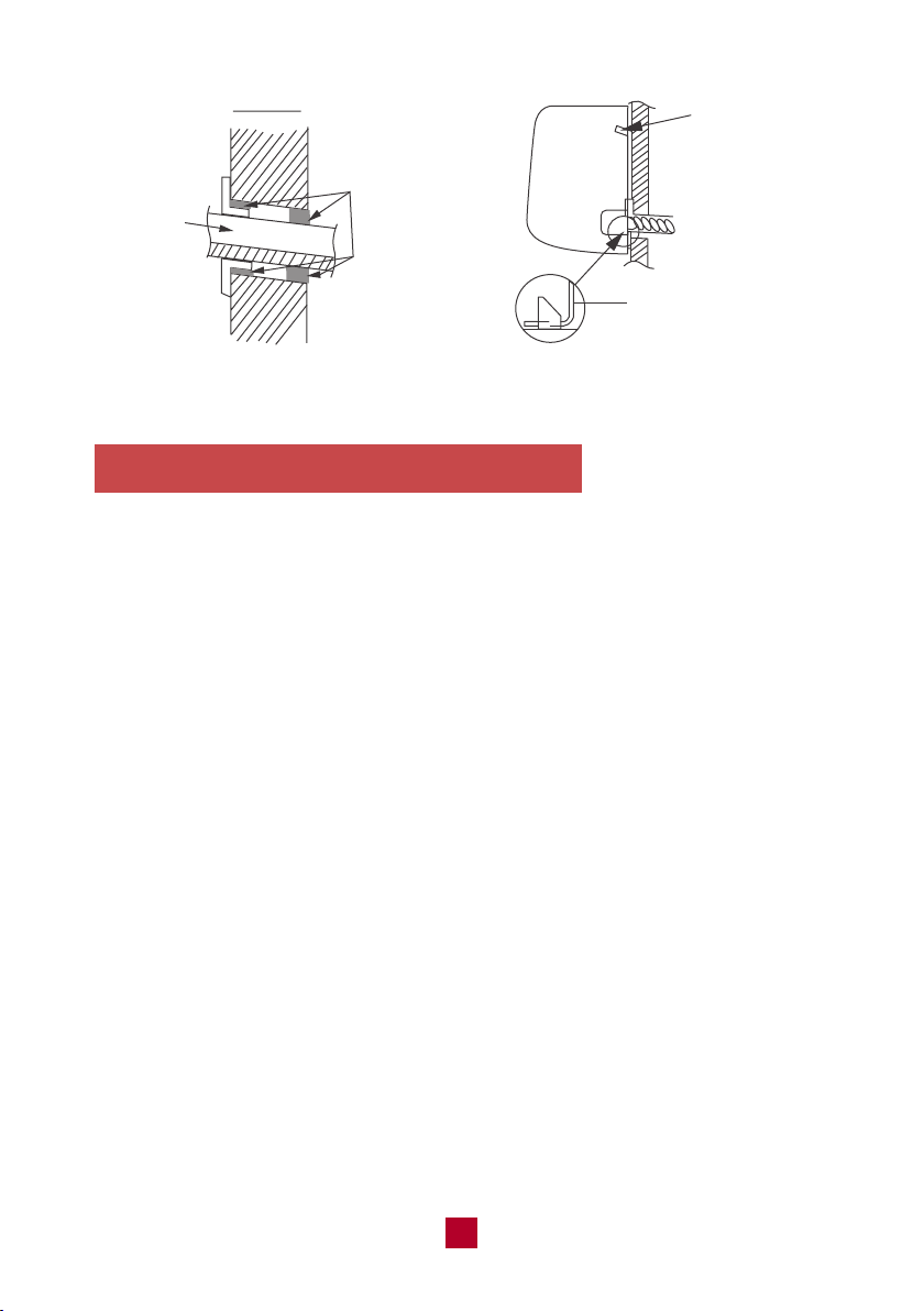
● Drill a hole with a 2.2/2.8 inch (55/70 mm) diameter through the wall where you
want the pipe to go through. To ensure better drainage, slope the hole at a slight
5-10 degree angle downwards. The hole should be drilled lower than the
mounting plate, as shown in the example figure below.
Indoor outdoor
Indoor unit
5-10°
● Place the protective wall cuff in the hole. This protects the edges of the hole and
will help seal the hole when you finish installation.
33
7. Extend the pipe by unwinding it
● Extending the pipes should be clung to the wall, bent slowly. The minimum
radius of bending the pipe should not exceed 4 in (10 cm).
● If the pipe is repeatedly bent or extended, it will become hard and difficult to
manipulate. Avoid bending or extending the pipe for more than 3 times.
● Make sure the pipe connector is protected from dirt and debris when the pipe
passes through the wall. Covering the connections with tape could do the trick.
indoor
bundle
of pipes
outdoor
sealing gum
upper hook
lower hook of
wall-mounting frame
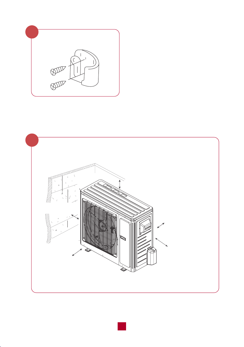
34
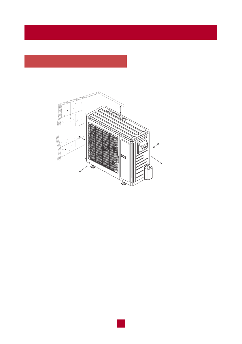
Outdoor Unit Installation
minimum 19.7in (50 cm)
minimum 78.7in (200 cm)
1. Select a Installation Site
Refer to the following diagram to ensure proper space around the unit:
minimum 19.7in (50 cm)
minimum 11.8 in (30 cm)
Appropriate install locations should follow these standards:
● Open ventilation space around the air conditioner to ensure airflow.
● Location must be convenient to install and not disturb others.
● Protected from prolonged periods of direct sunlight exposure.
● Strong enough to support the weight of the unit.
DO NOT install the unit in the following locations:
● Near an obstacle that will block air inlets and outlets.
● Near a public street, crowded areas, or where noise from the unit will disturb
others.
● Near animals or plants that will be harmed by hot air discharge.
● Near any source of combustible gas or area that is exposed to large amounts
of dust.
● Near excessive amounts of salty air.
minimum
11.8 in (30 cm)
35
Note: If the unit is frequently exposed to heavy rain or snow. Build a shelter
above the unit to protect it. Be careful not to obstruct airflow around the unit.
Note: In cold climates make sure that the drain hose is as vertical as possible
to ensure swift water drainage. If water drains too slowly it can freeze and
cause malfunction.
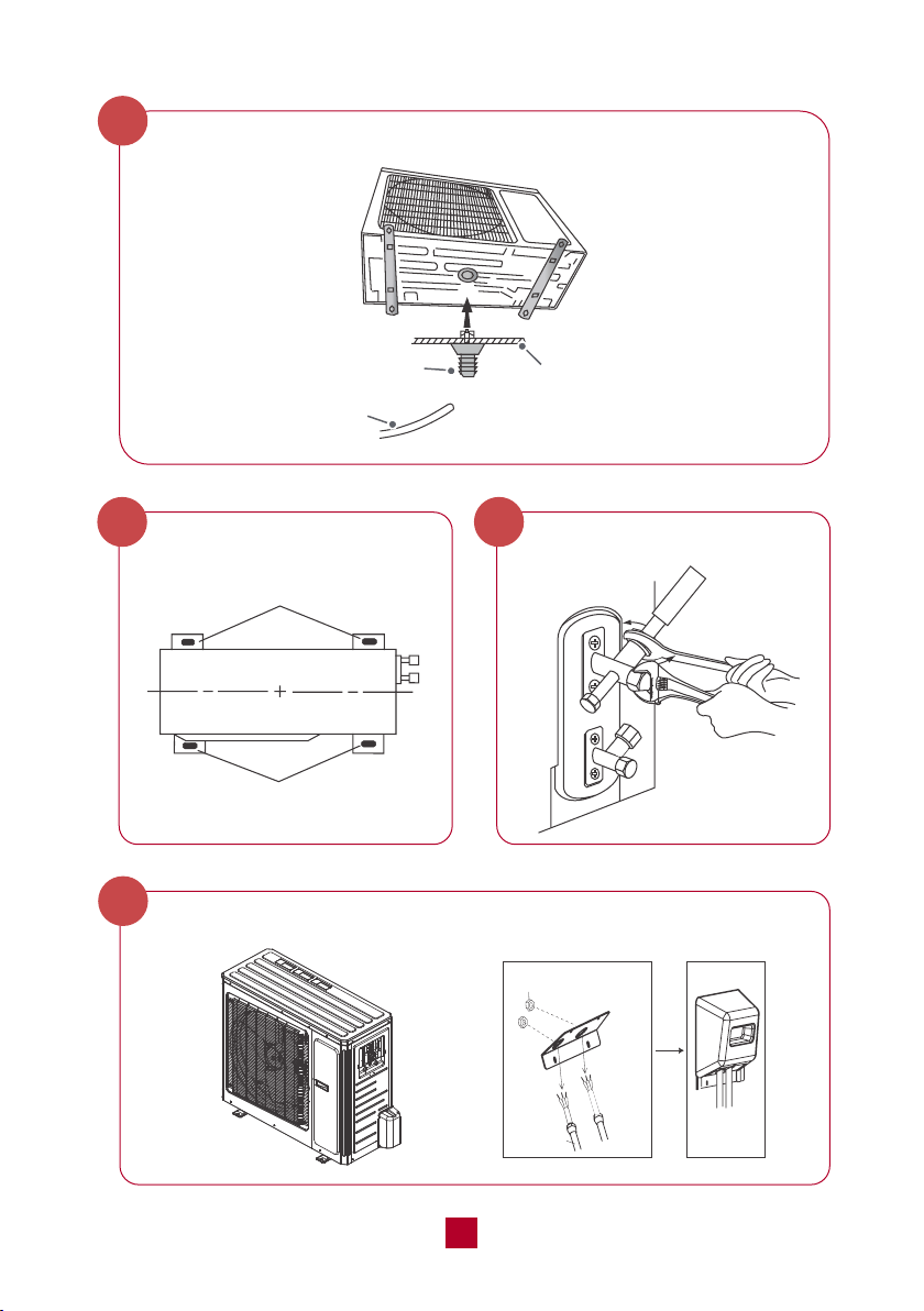
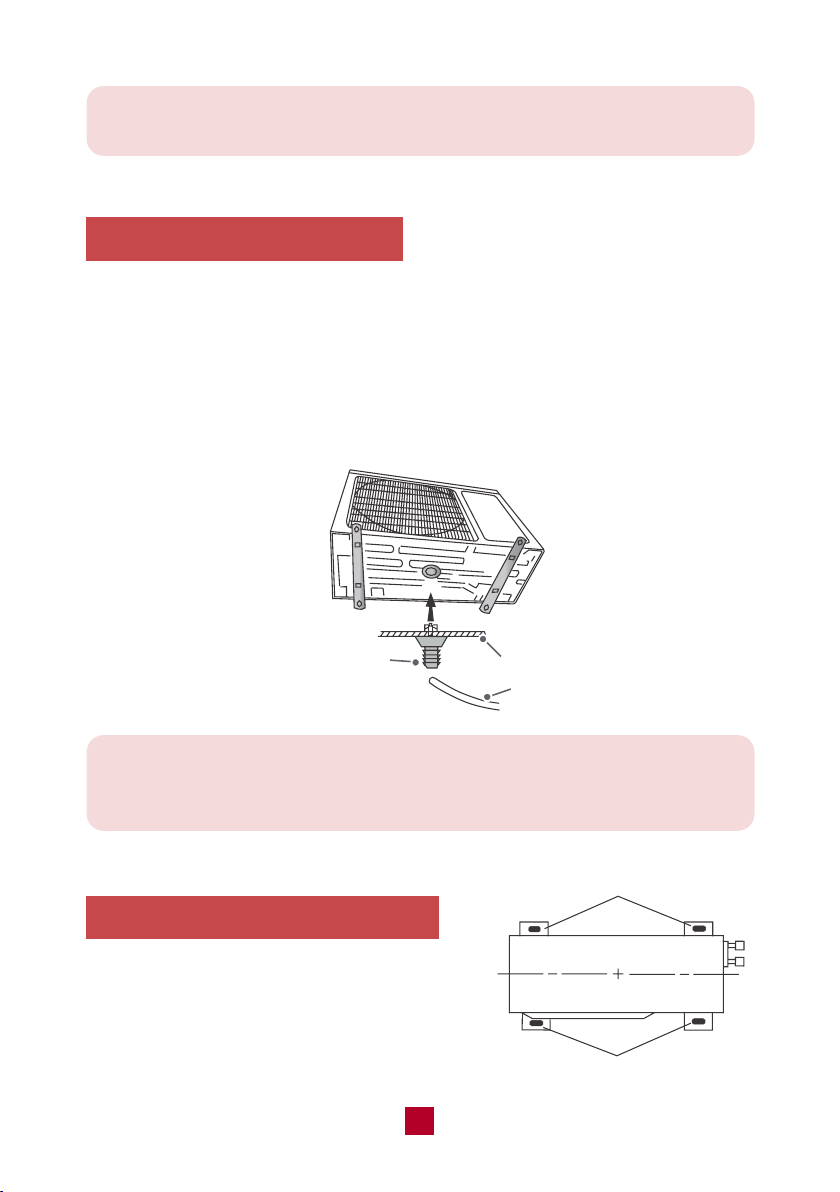
2. Install the Drain Joint
Heat pump units require a drain joint if the unit is elevated off the ground. Before
bolting the outdoor unit in place, you must install the drain joint at the bottom of
the unit.
● Connect the outdoor drain joint into the hole in the base pan of the unit, as
shown in the picture below.
● Connect the drain hose into the drain joint.
3. Secure the Outdoor Unit
Place the outside unit firmly on the ground or
attach it to a secure metal wall bracket or pad
(not included). Secure the foot holes of the
outdoor unit with the bolts.
chassis
drain joint
Drain hose
foot holes
foot holes
36
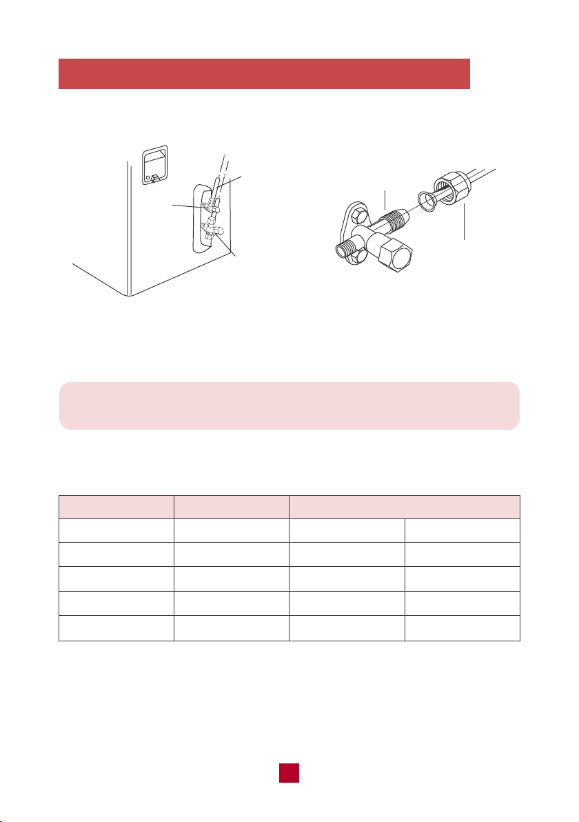
Note: Over tightening may damage connections. Carefully tighten union nuts
to correct torque level referring to the Torque Table below.
4. Connect the Refrigerant Pipe to Outdoor Unit
● Remove the screw cap of the valve and aim the pipe joint at the bellmouth of pipe.
Pipe Diameter Nut Size
1/4 (6)
3/8 (9.5)
1/2 (12.7)
5/8 (16)
Torque Table
Tightening Torque
inch (mm)inch (mm) ft-lbs N-m
1/4 (17)
3/8 (22)
1/2 (25)
5/8 (29)
10 to 13
25 to 30
36 to 45
50 to 60
15 to 20
30 to 40
45 to 55
60 to 65
refrigerant
pipes
gas valve
pipe joint
union nut
liquid
valve
● Align both ends of the refrigerant piping and start to twist on the union nut by hand.
● Use a standard wrench on the pipe joint and an open-end torque wrench on the
union nut to apply the proper torque as shown in the torque table below.
37
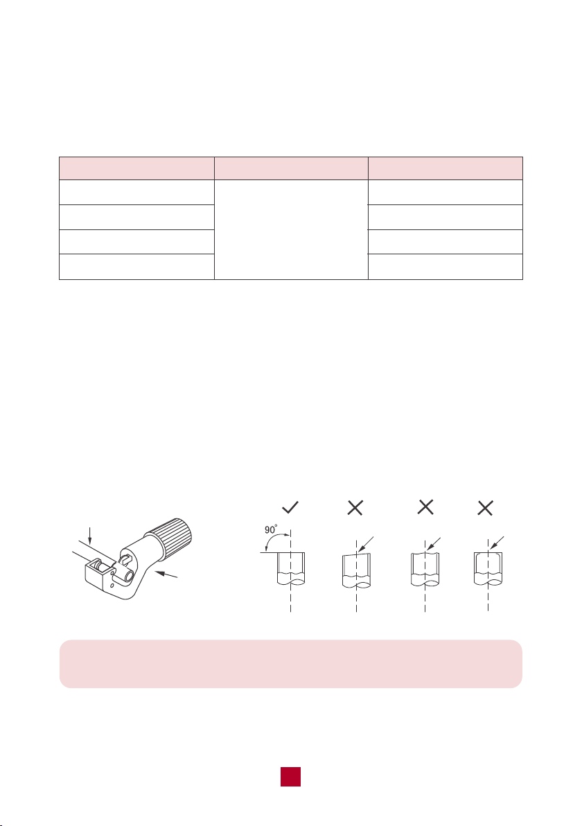
Be extra careful not to damage, dent, or deform the pipe while cutting.
This will drastically reduce the heating efficiency of the unit.
Capacity (BTU/h)
Min. Length (ft/m)
5,000 - 9,000
12,000
18,000 - 24,000
28,000 - 48,000
Max. Length (ft/m)
49 ft (15 m)
65 ft (20 m)
82 ft (25 m)
98 ft (30 m)
Note On Pipe Length
The length of refrigerant piping will affect the performance and energy efficiency of
the unit. Nominal efficiency is tested on units with a pipe length of 16.5ft (5 meters).
Refer to the table below for specifications on the maximum length.
10 ft (3 m)
Refrigerant Piping Connection Instructions
Improper pipe shorten or expanding might cause refrigerant leakage. Please take
extra care to cut and flare them properly to ensure the efficient operation and
minimize the need for future maintenance.
a. Cut pipes
● Measure the distance between the indoor and outdoor units.
● Using a pipe cutter, cut the pipe a little longer than the measured distance.
● Make sure that the pipe is cut at a perfect 90° angle.
pipe cutter
pipe
leaning
uneven burr
38
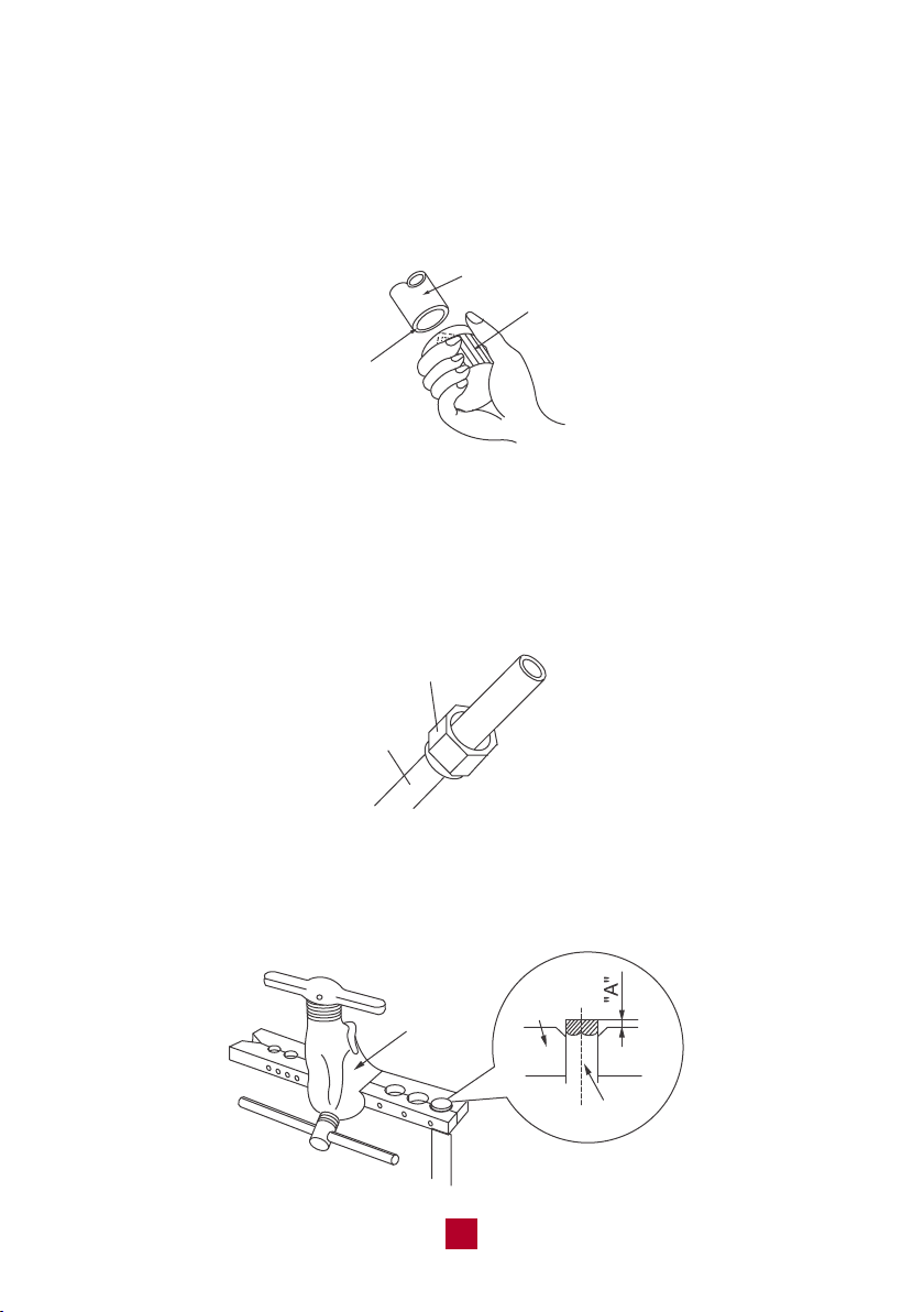
b. Remove burrs
Burrs can affect the air-tight seal of refrigerant piping connection. They must be
completely removed.
● Hold the pipe at a downward angle to prevent burrs from falling into the pipe.
● Using a reamer or deburring tool, remove all burrs from the cut section of the pipe.
shaper
downwards
pipe
c. Flare pipe ends
● After removing burrs from the cut pipe, seal the ends with tape to prevent foreign
materials from entering the pipe.
● Sheath the pipe with insulating material.
● Place flare nuts on both ends of the pipe. Make sure they are facing in the right
direction, because you can’t put them on or change their direction after flaring.
flare nuts
pipe
● Remove the tape from ends of pipe when ready to perform flaring work.
● Clamp flare form on the end of the pipe. Place flaring tool onto the form.
Turn the handle of the flaring tool clockwise until the pipe is fully flared.
expander
pipe
hard
mold

39
The end of the pipe(“A”) must extend beyond the edge of the flare form in
accordance with the dimensions shown in the table below.
A(mm)
Max Min
Φ6 - 6.35(1/4")
1.3 0.7
Φ9 - 9.52(3/8") 1.6 1.0
Φ12-12.7(1/2")
1.8 1.0
Φ15.8-16(5/8")
2.4 2.2
Outer diameter
(mm)
● Remove the flaring tool and flare form, then inspect the end of the pipe for cracks
and even flaring. If there is any blemish, do it again according to the steps above.
smooth surface
improper expanding
the length is equal
uneven
thickness
leaning damaged crack
surface
d. Connect pipes
When connecting refrigerant pipes, be careful not to use excessive torque or to
deform the piping in any way. You should first connect the low-pressure pipe, then
the high-pressure pipe.
40
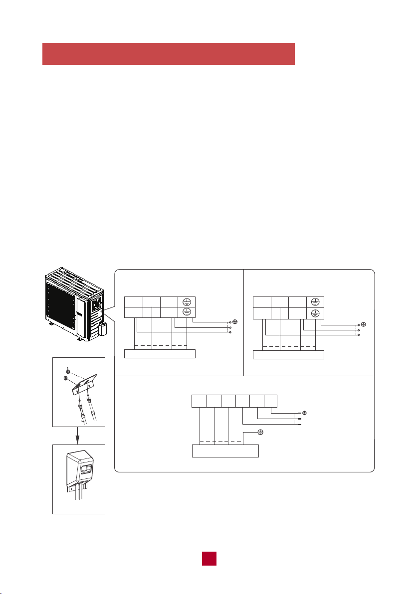
5. Connect the Signal and Power Cables
● Remove the wire cover on the outdoor unit. All wiring must be performed in
accordance with the wiring diagrams shown below.
● Match the wire colors with the labels on the terminal block and firmly screw the
U-Lug of each wire to its corresponding terminal on the terminal block.
● After checking to make sure every connection is secure, loop wires around the
terminals to secure the connection.
● Use a cable clamp to fasten the cable to the unit. Screw the cable clamp down
tightly.
● Insulate unused wires with PVC electrical tape. Arrange them so that they do
not touch any electrical or metal parts.
● Replace the wire cover on the side of the unit and screw it in place.
WIRE CONNECTING DIAGRAM
L1 L2
N L
black
9,000 BTU 120V
12,000 BTU 120V
N(1) 2 3
black
outdoor
unit connection
lock nut
outdoor
unit connection
Finish
conduit
2 3 L1 L2 G
red
black
outdoor
unit connection
N(1) 2 3
black(brown)
white
(blue)
green
(yellow-green)
green
black(brown)
(
yellow-
green
)
green
(
yellow-
green
)
white
(blue)
green
(yellow-green)
L2
L1
POWER
L
N
POWER
white
(blue)
red
(brown)
white
(blue)
red
(brown)
N(1)
green(yellow-green)
18,000 BTU 230V
white(blue)
black
(brown)
L2
L1
POWER
green
(brown)
(yellow-
green)
white
(blue)
9,000 BTU 230V
12,000 BTU 230V
NOTE
1. Make sure the connection is following the instruction. You can make
adjustments according to your circuit box at home, if necessary, it is
recommended to consult a professional electrician.
2. The wire gauge recommended for this product is listed below.
41
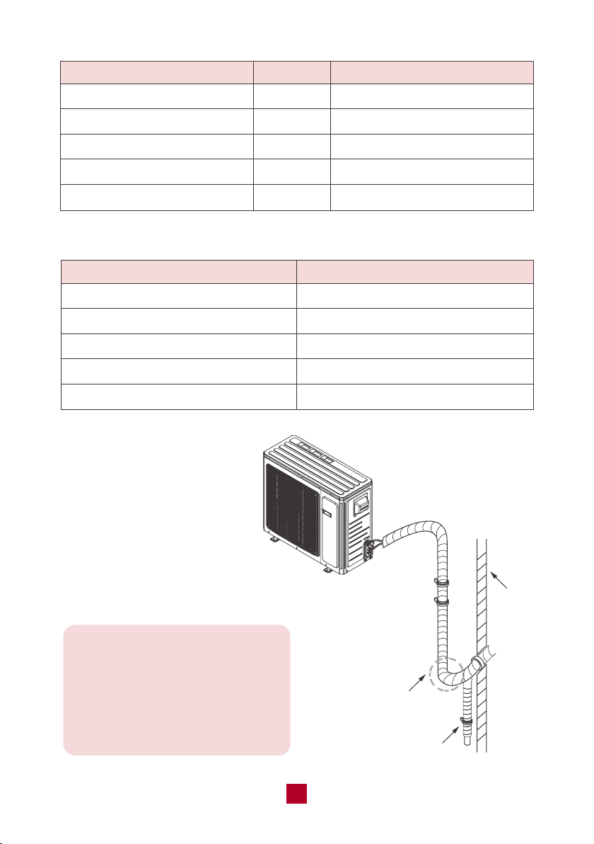
Note: If the outdoor unit is placed
higher than the wall hole you will
need to set a U-shaped curve in
the pipe before the pipe goes into
the room, in order to prevent rain
from getting into the room.
U-shaped curve
wall
drain hose
Minimum Cross-Sectional Area of Power and Signal Cables North American
Model
GWH09AFC-A3DNA1A
GWH09AFC-D3DNA1A
GWH12AFC-A3DNA1A
GWH12AFC-D3DNA1A
GWH18AFD-D3DNA1A
MCA
13A
9A
21A
9A
13A
Recommended Wire Gauge
AWG 16+
AWG 18+
AWG 12+
AWG 18+
AWG 16+
Appliance Amps (A)
10
13
18
25
30
AWG
18
16
14
12
10
42
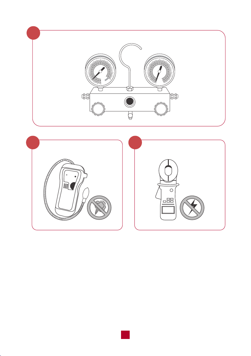
Air Evacuation
Preparations and Precautions
Air and foreign matter in the refrigerant circuit can cause abnormal rises in
pressure, which can damage the air conditioner, reduce its efficiency, and
cause injury. Use a vacuum pump and manifold gauge to evacuate the refrigerant
circuit, removing any non-condensable gas and moisture from the system.
Evacuation should be performed upon initial installation or when the unit is
relocated.
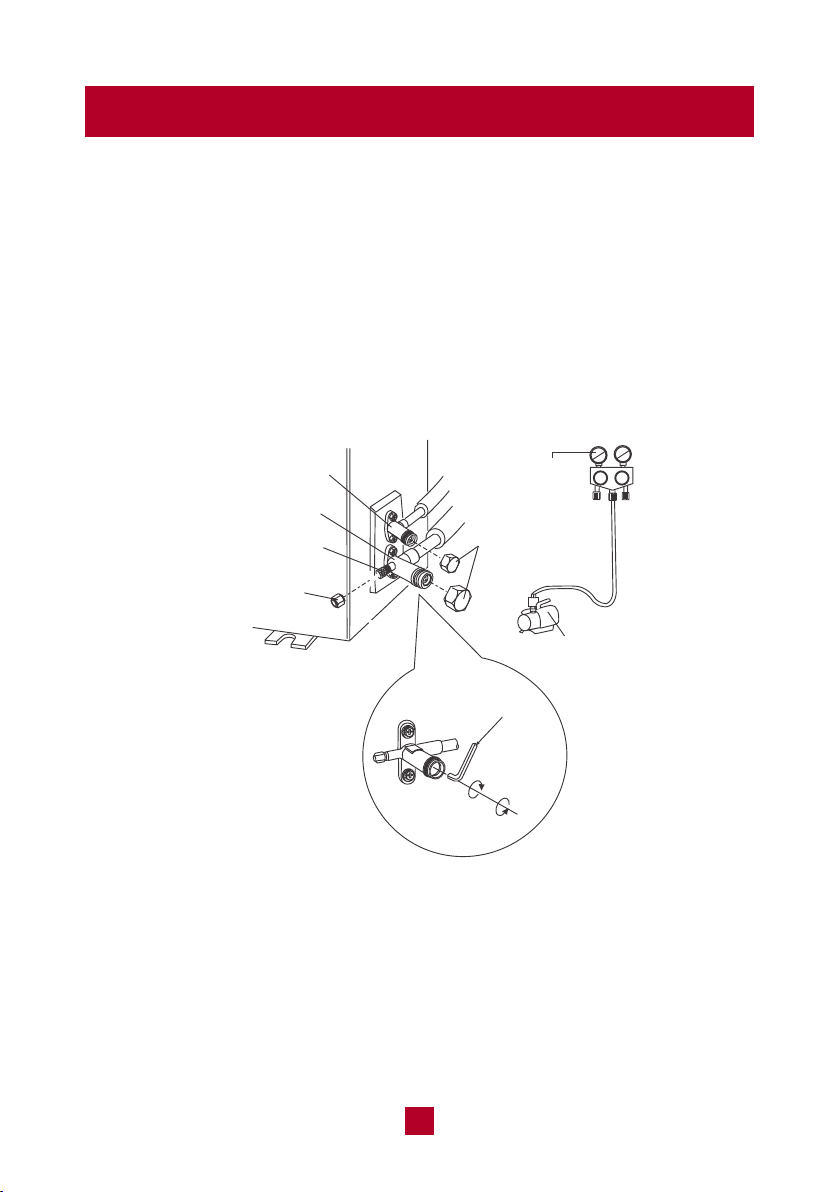
Evacuation Instructions
liquid valve
gas valve
refrigerant charging
vent
nut of refrigerant
charging vent
vacuum pump
Manifold
Gauge
valve cap
Lo Hi
open
close
● Remove the valve caps from the liquid valve and gas valve and remove the nut
of the refrigerant charging vent.
● Connect the charging hose of the manifold gauge to the refrigerant charging
vent of the gas valve and then connect the other charging
hose from the manifold gauge to the vacuum pump.
● Open the manifold gauge completely and operate for 10-15min to check if the
pressure of the manifold gauge remains in -0.1MPa.

43
Note: After confirming that all the pipe connection points DO NOT leak,
replace the valve cover on the outside unit.
Gas Leak Checks
There are two different methods to check for gaseous leaks.
1. Soap and Water Method
Using a soft brush, apply soapy water or liquid detergent to all pipe connection
points on the indoor unit and outdoor unit for more than 3 minutes. If there are
bubbles coming out, there’s a leak.
2. Leak Detector Method
If using a leak detector, refer to the device’s operation manual for proper usage
instructions.
Electrical Safety Checks
After installation, confirm that all electrical wiring is installed in accordance with
local and national regulations, and according to the Installation Manual.
1. Check Grounding Work
Measure grounding resistance by visual detection and with a grounding
resistance tester. Grounding resistance must be less than 4 ohms.
Note: This may not be required for some locations in the US.
● Close the vacuum pump and wait for 5 minutes to ensure there has been no
change in system pressure. If the pressure decreases there may be leakage,
please refer to the Gas Leak Check section.
● Remove the manifold gauge, open the valve core of the liquid valve and gas
valve completely by turning anticlockwise with a hexagonal allen wrench.
● Tighten the screw caps of the valves and refrigerant charging vent once complete.

44
Note: All wiring must comply with local and national electrical codes and
must be installed by a licensed electrician.
Test Run
Only perform test run after you have completed the following steps
• Electrical Safety Check – Confirm that the unit’s electrical system is safe and
operating properly
• Gas Leak Check – Check all flare nut connections and confirm that the system
is not leaking
• Confirm that gas and liquid (high and low pressure) valves are fully open
2. Check for Electrical Leakage
During the Test Run, use an electroprobe and multimeter to perform a
comprehensive electrical leakage test.
If electrical leakage is detected, turn off the unit immediately and call a licensed
electrician to find and resolve the cause of the leakage.
Note: This may not be required for some locations in the US.
45
Warranty & Customer Support
Warranty Information
1. 5-Year warranty:
TOSOT Split-type Air Conditioner comes with a 5-year warranty from the date
of purchase.
This warranty covers manufacturing and material defects. Please visit
https://tosotdirect.com/warranty for more details.
2. Additional 6-Month warranty extension:
You can get a 6-month warranty extension by registering your new product at
www.tosotdirect.com/extend.
Customer Support
Questions? We are here to help
www.tosotdirect.com
@tosotdirect
Share your experience