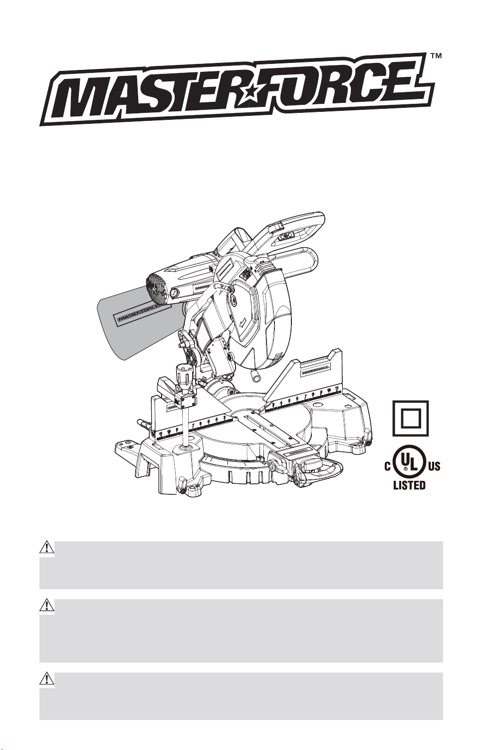
OPERATING MANUAL
12-in.Compound Miter Saw with
Dual-Laser line
240-0024
IMPORTANT :
Carefully read this Owner’s Manual before using this tool. Pay close atten-
tion to all Safety Instructions, Warnings, and Caution sections. Use this tool
properly, and only for its intended use.
Safety symbols in this manual are used to flag possible dangers. The safety
symbols and their explanations require the operator’s full understanding. The
safety warnings do not, by themselves, eliminate any danger, and they are not
a substitute for proper accident prevention measures.
This Safety Alert Symbol indicates caution, warning, or danger. Failure to
obey a safety warning can result in serious injury to yourself or others. To reduce
the risk of injury, fire, or electric shock, always follow the safety precautions.
Downloaded from www.Manualslib.com
manuals search engine

2
TABLE OF CONTENTS
Specifications ................................................................................................. Page 2
Rules for Safe Operation ..............................................................................Page 3
Description ...................................................................................................... Page 11
Adjustments .................................................................................................... Page 15
Operation ......................................................................................................... Page 20
Maintenance...................................................................................................Page 34
Troubleshooting .............................................................................................. Page 39
Exploded View & Part List ............................................................................Page 40
Warranty .......................................................................................................... Page 48
PRODUCT SPECIFICATIONS
Model 240-0024
Supply power 120V, 60Hz
Rated current 15A
No load speed 4000RPM
Saw blade 12”x/1” 60T
Miter angle 50° left to 55° right
Bevel angle 48° left to 48° right
CUTTING CAPACITIES
Type of cut Angle Setting Maximum cutting capacity
Miter Bevel Thickness Width
Cross Cut 0° 0° 3 3/4-in. 7 3/4-in
Miter cut 45° 0° 3 3/4-in. 5 1/2-in
Bevel cut at
45° Right
0° 45° 1 1/2-in. 7 1/2-in
Bevel cut at
45° Left
0° 45° 1 7/8-in. 7 1/2-in
Compound cut 45° 45° 1 1/2-in. 5 1/2-in
NOTE: All cutting specifications will vary by blade type used, actual lumber
size,and compound miter saw. All dimensions are approximate.
Downloaded from www.Manualslib.com
manuals search engine

3
RULES FOR SAFE OPERATION
KNOW YOUR TOOL
Before operating this tool, carefully read this operating manual and all of the
labels affixed to the router. Keep this manual available for future reference.
IMPORTANT
This tool should only be serviced by a qualified service technician.
READ ALL INSTRUCTIONS THOROUGHLY
GENERAL SAFETY RULES FOR ALL POWER TOOLS
WARNING! Read and understand all instructions. Failure to follow all in-
structions listed below may result in electric shock, fire and/or serious per-
sonal injury.
1. KEEP GUARDS IN PLACE and in working order.
2. REMOVE ADJUSTING KEYS AND WRENCHES. Form habit of checking
to see that keys and adjusting wrenches are removed from tool before
turning it on.
3. KEEP WORK AREA CLEAN. Cluttered areas and benches invite accidents.
4. DON’T USE IN DANGEROUS ENVIRONMENT. Don’t use power tools in
damp or wet locations, or expose them to rain. Keep work area well
lighted.
5. KEEP CHILDREN AWAY. All visitors should be kept safe distance from work
area.
6. MAKE WORKSHOP KID PROOF with padlocks master switches, or by
removing starter keys.
7. DON’T FORCE TOOL It will do the job better and safer at the rate for which
it was designed.
8. USE RIGHT TOOL Don’t force tool or attachment to do a job for which it
was not designed.
9. USE PROPER EXTENSION CORD. Make sure your extension cord is in good
condition. When using an extension cord, be sure to use one heavy enough
to carry the current your product will draw. An undersized cord will cause
a drop in line voltage resulting in loss of power and overheating. Table 1
shows the correct size to use depending on cord length and nameplate
ampere rating. If in doubt, use the next heavier gage. The smaller the gage
number, the heavier the cord.
Downloaded from www.Manualslib.com
manuals search engine

4
Recommended sizes of extension cords
Tool’s Ampere
rating
Volts Total length of cord in feet Cord size in
A.W.G.(minimum)
25’ 50’ 100’ 150’
0-6 120V~ 18 16 16 14
6-10 18 16 14 12
10-12 16 16 14 12
12-16 14 12 Not Recommended
10. WEAR PROPER APPAREL Do not wear loose clothing, gloves, neckties,
rings, bracelets, or other jewelry which may get caught in moving parts.
Nonslip footwear is recommended. Wear protective hair covering to
contain long hair.
11. ALWAYS USE SAFETY GLASSES. Also use face or dust mask if cutting
operation is dusty. Everyday eyeglasses only have impact resistant
lenses, they are NOT safety glasses.
12. SECURE WORK. Use clamps or a vise to hold work when practical. It’s
safer than using your hand and it frees both hands to operate tool.
13. DON’T OVERREACH. Keep proper footing and balance at all times.
14. MAINTAIN TOOLS WITH CARE. Keep tools sharp and clean for best and
safest performance. Follow instructions for lubricating and changing
accessories.
15. DISCONNECT TOOLS before servicing; when changing accessories, such
as blades, bits, cutters, and the like.
16. REDUCE THE RISK OF UNINTENTIONAL STARTING. Make sure switch is
in off position before plugging in.
17. USE RECOMMENDED ACCESSORIES. Consult the owner’s manual for
recommended accessories. The use of improper accessories may cause
risk of injury to persons.
18. NEVER STAND ON TOOL. Serious injury could occur if the tool is tipped or
if the cutting tool is unintentionally contacted.
19. CHECK DAMAGED PARTS. Before further use of the tool, a guard or other
part that is damaged should be carefully checked to determine that it will
operate properly and perform its intended function-check for alignment of
moving parts, binding of moving parts, breakage of parts, mounting, and
any other conditions that may affect its operation, A guard or other part
that is damaged should be properly repaired or replaced.
Downloaded from www.Manualslib.com
manuals search engine
5
20. DIRECTION OF FEED. Feed work into a blade or cutter against the
direction of rotation of the blade or cutter only.
21. NEVER LEAVE TOOL RUNNING UNATTENDED. TURN POWER OFF. Don’t
leave tool until it comes to a complete stop.
DOUBLE-INSULATED TOOLS
1. Replacement Parts
When servicing use only identical replacement parts.
2. Polarized Plugs
To reduce the risk of electric shock, this equipment has a polarized plug
(one blade is wider than the other). This plug will fit in a polarized outlet
only one way. If the plug does not fit fully in the outlet, reverse the plug. If it
still does not fit, contact a qualified electrician to install the proper outlet.
Do not change the plug in any way.
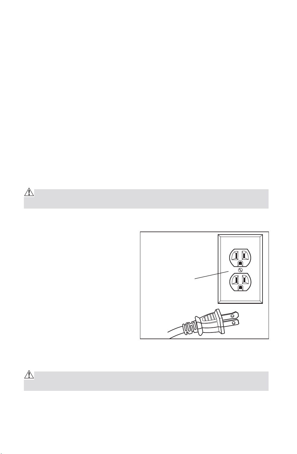
ELECTRICAL SAFETY
WARNING: Do not permit fingers to touch the terminal or plug when in-
stalling or removing the plug from an outlet.
To reduce the risk of electric shock, Double insulated tools are equipped
with a polarized plug (one blade
is wider than the other). This
plug will fit in a polarized outlet
only one way. If the plug does not
fit fully in the outlet, reverse the
plug. If it still does not fit, contact
a qualified electrician to install a
polarized outlet. Do not change
the plug in any way.
Double insulation eliminates the
need for the three-wire grounded
power cord and grounded power
supply system. Applicable only
to Class II (double-insulated) tools. This compound miter saw is a double
insulated tool.
WARNING: Double insulation DOES NOT take the place of normal safety
precautions when operating this tool.
BEFORE plugging in the tool, BE SURE that the outlet voltage supplied is
within the voltage marked on the tool’s data plate. DO NOT use “AC only”
rated tools with a DC power supply.
Cover of Grounded
Outlet Box
Downloaded from www.Manualslib.com
manuals search engine
6
AVOID body contact with grounded surfaces, such as pipes, radiators,
ranges and refrigerators. There is an increased risk of electric shock if
your body is grounded.
DO NOT expose power tools to rain or wet conditions or use power tools in
wet or damp locations. Water entering a power tool will increase the risk
of electric shock. This tool is intended for indoor use only.
If operating a power tool in damp locations is unavoidable, ALWAYS USE
a Ground Fault Circuit Interrupter to supply power to your tool. ALWAYS
WEAR electrician’s rubber gloves and footwear in damp conditions.
INSPECT tool cords for damage. Have damaged tool cords repaired by
qualified person. BE SURE to stay constantly aware of the cord location
and keep it well away from the moving blade.
DO NOT abuse the cord. NEVER use the cord to carry the tool by or to
pull the plug from the outlet. Keep cord away from heat, oil, sharp edges
or moving parts. Replace damaged cords immediately. Damaged cords
increase the risk of electric shock.
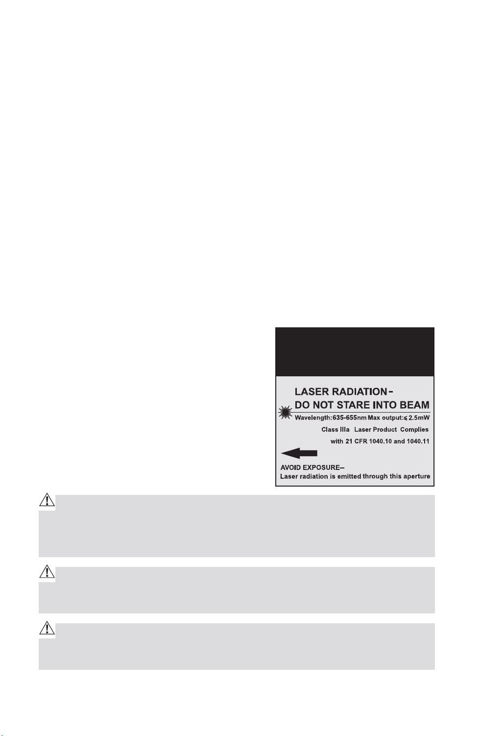
SAFETY PRECAUTIONS FOR LASERS
This miter saw has a built-in laser light.
The laser is a Class IIla and emits output
power of a maximum 2.5mW and 635-665nm
wavelengths. These lasers do not normally
present an optical hazard. However, DO NOT
stare at the beam as this can cause flash
blindness.
CAUTION: The following label is on your tool. It indicates where the saw
emits the laser light. BE AWARE of the laser light location when using. AL-
WAYS MAKE SURE that any bystanders in the vicinity of use are made aware
of the dangers of looking directly into the laser.
WARNING: LASER LIGHT. LASER RADIATION. Avoid Direct Eye Exposure.
DO NOT stare into beam. Only turn laser beam on when the saw is on the
workpiece.
WARNING: Use of controls, adjustments or performance of procedures
other than those specified in this manual may result in hazardous radiation
exposure.
CAUTION
Downloaded from www.Manualslib.com
manuals search engine

7
WARNING: The use of optical instruments such as, but not limited to, tele-
scopes or transits to view the laser beam will increase eye hazard.
1. The laser shall be used and maintained in accordance with the
manufacture’s instruction.
2. Never aim the beam at any person or an object other than the work piece.
3. Always ensure the laser beam is aimed at a sturdy work piece without
reflective surface. I.e. wood or rough coated surface are acceptable.
Bright shiny reflective sheet or the like is not suitable for laser use as the
reflective surface could direct the beam back at the operator.
4. Do not attempt to activate the laser when the tool housing is removed.
5. The laser is activated by means a button switch independent with the main
switch of the saw.
6. Do not change the laser light assembly with a different type. Any repairs
must only be carried out by the laser manufacture or authorized service
agent.
7. Do not attempt to repairs the laser guide by yourself.
8. Do not attempt to change any parts of the laser guide.
SPECIFIC SAFETY RULES FOR MITER Saw
1. ALWAYS wear eye protection.
2. DO NOT operate saw without guards in place.
3. BE SURE turn off tool and wait for saw blade to stop before moving
workpiece or changing settings.
4. BE SURE disconnecting power before changing blade or servicing.
5. DO NOT expose to rain or use in damp location.
6. WHEN SERVICING, use only identical replacement parts.
7. ALWAYS firmly clamp or bolt your miter saw to a secure, stable
workbench or table at approximately hip height.
8. BE SURE that all adjustments are secure BEFORE making a cut.
9. ALWAYS make sure that the miter table and saw arm (bevel function) are
locked in position BEFORE operating your saw. Lock the miter table by
securely tightening the miter lock lever. Lock the saw arm (bevel function)
by securely tightening the bevel lock knob.
10. BE SURE that the blade path is free of nails. ALWAYS carefully inspect
lumber and remove all nails BEFORE cutting.
Downloaded from www.Manualslib.com
manuals search engine

8
11. ALWAYS be sure that the blade clears the workpiece. NEVER start the
saw with the blade touching the workpiece. ALWAYS allow the motor to
come up to full speed BEFORE starting a cut.
12. SUPPORT long workpieces when cutting to minimize the risk of blade
pinching or kickback. The saw may slip, walk or slide while cutting long or
heavy boards.
13. NEVER use a length-stop on the free (scrap end) of a clamped workpiece,
NEVER hold onto or bind the free scrap end of the workpiece in any
operation. If work clamp and length stop are used together, THEY MUST
BOTH BE INSTALLED on the SAME SIDE of the saw table to prevent the
saw from catching the loose end and kicking up.
14. NEVER cut more than one piece at a time. DO NOT STACK more than one
workpiece on the worktable at a time.
15. AVOID awkward operations and hand positions where a sudden slip
could cause your hand to move into the blade. ALWAYS make sure that
you have good balance. NEVER operate your saw on the floor or in a
crouched position.
16. ONLY USE the correct blades. Use the right blade size, style and cutting
speed for the material and the type of cut. DO NOT use blades with
incorrect size holes. NEVER use blade washers or blade bolts that are
defective or incorrect. The maximum blade capacity for this saw is
12-inches.
17. ALWAYS keep blades clean, sharp and with the sufficient set. Sharp
blades minimize stalling and kickback.
18. DO NOT use dull or damaged blades. Bent blades can break easily, or
cause kickback.
19. DO NOT remove the saw’s blade guards. NEVER operate the saw with
any guard or cover removed. MAKE SURE that all guards are operating
properly BEFORE each use.
20. NEVER hand holds a workpiece that is too small to be clamped. ALWAYS
keep your hands clear of the “no hands” zone.
21. NEVER perform any operation freehand. ALWAYS place the workpiece to
be cut on the miter saw table and position it firmly against the fence as a
backstop. ALWAYS use the fence.
22. NEVER apply lubricants to the blade when it is running. NEVER use
solvents to clean plastic parts. Solvents could possibly dissolve or
otherwise damage the material.
23. KEEP HAND OUT OF SAW BLADE. DO NOT reach under the material being
cut or in the blade’s cutting path with your fingers or hand for any reason.
Downloaded from www.Manualslib.com
manuals search engine

9
24. DO NOT turn the motor switch on and off rapidly. This could cause the
blade to loosen, which could create a hazard. Should this ever occur,
stand clear and allow the saw blade to come to a complete stop.
Disconnect the saw from the power source and securely tighten the
blade bolt.
25. ALWAYS turn off the saw before disconnecting it to avoid accidental
starting when reconnecting the saw to a power supply. NEVER leave the
saw unattended while connected to a power supply.
26. KEEP THE MOTOR AIR SLOTS clean and free of chips or dust. To avoid
motor damage, the motor should be blown out or vacuumed frequently to
keep sawdust from interfering with the motor ventilation.
27. NEVER lift this tool by gripping the cutting handle or the miter fence. This
may cause misalignment. ALWAYS carry saw by holding the base or carry
by the support bracket/carrying handle after you have locked the saw
arm in the “DOWN” position.
ADDITIONAL RULES FOR SAFE OPERATION
WARNING: Use of this tool can generate and/or disburse dust, which may
cause serious and permanent respiratory or other injury. Always use NIOSH/
OSHA approved respiratory protection appropriate for the dust exposure. Di-
rect particles away from face and body.
Know your power tool. Read operator’s manual carefully. Learn the
applications and limitations, as well as the specific potential hazards
related to this tool. Following this rule will reduce the risk of electric shock,
fire or serious injury.
ALWAYS wear safety glasses or eye shields when using this saw. Everyday
eyeglasses have only impact-resistant lenses; they are NOT safety glasses.
All users and bystanders MUST wear eye protection that conforms to ANSI
Z87.1
PROTECT your lungs. Wear a face mask or dust mask if the operation is
dusty.
PROTECT your hearing. Wear appropriate personal hearing protection
during use. Under some conditions and duration of use, noise from this
product may contribute to hearing loss.
ALL VISTORS AND BYSTANDERS MUST wear the same safety equipment
that the operator of the saw wears.
INSPECT the tool cords periodically and if damaged have it repaired by
qualified person.
Downloaded from www.Manualslib.com
manuals search engine
10
ALWAYS check the tool for damaged parts. Before further use of the
tool, a guard or other part that is damaged should be carefully checked
to determine if it will operate properly and perform its intended function.
Check for misalignment or binding of moving parts, breakage of parts, and
any other condition that may affect the tool’s operation. A guard or other
part that is damaged should be properly repaired or replaced by qualified
person.
INSPECT and remove all nails from lumber before sawing.
SAVE THESE INSTRUCTIONS. Refer to them frequently and use them to
instruct others who may use this tool. If someone borrows this tool, make
sure they have these instructions also.
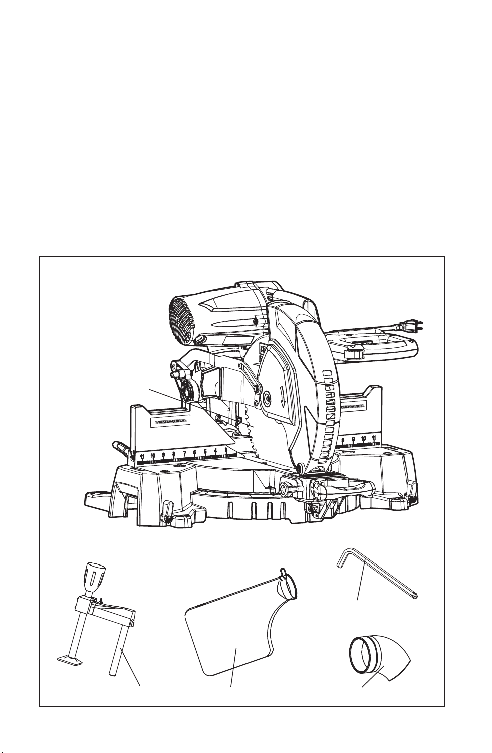
CARTON CONTENTS/LOOSE PARTS LIST (Fig.1)
Fig. 1
Hold down clamp
Dust bag
Blade wrench (Allen key)
Hose adapter
Saw with 60T blade
Downloaded from www.Manualslib.com
manuals search engine
11
DESCRIPTION
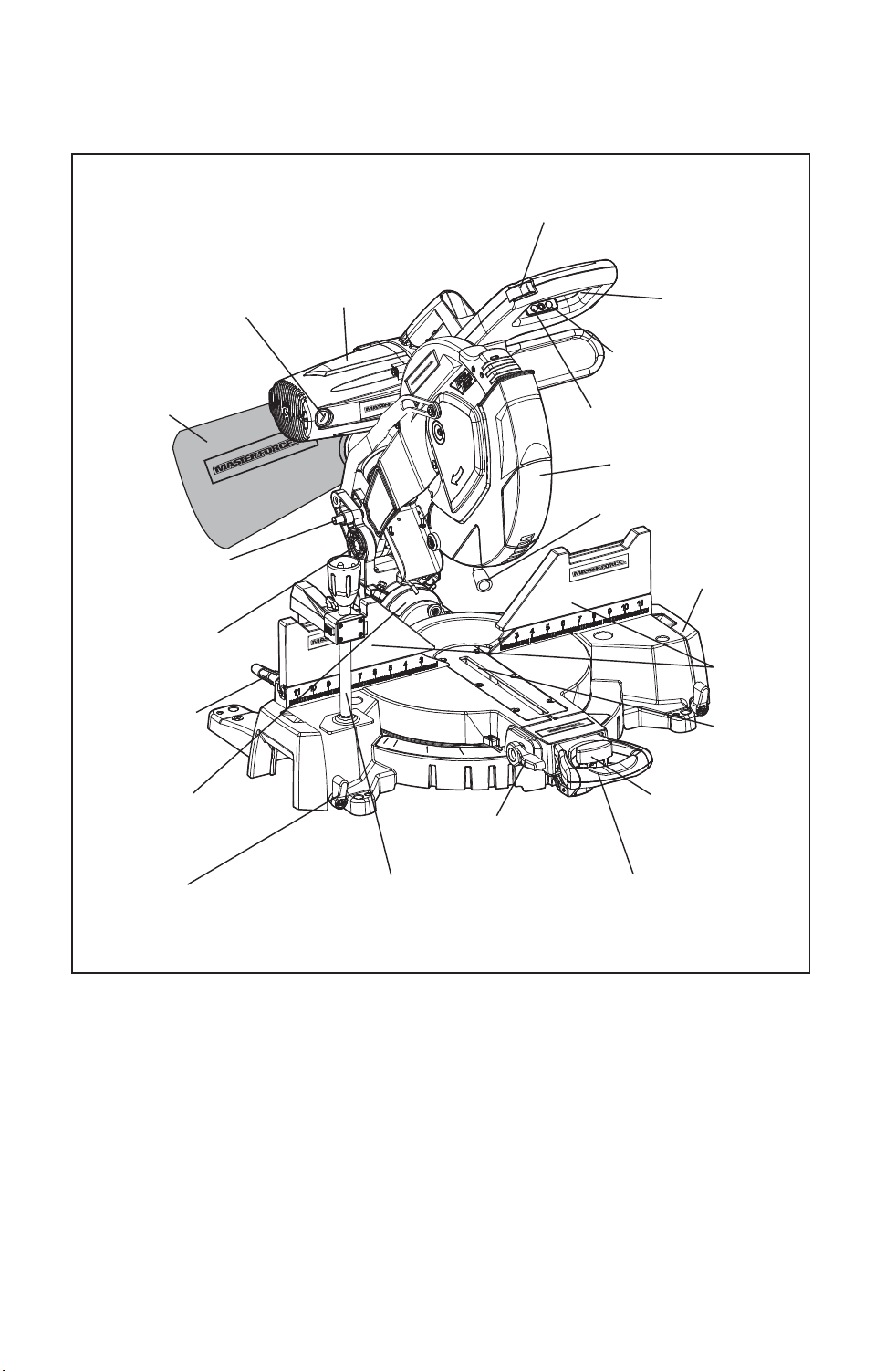
KNOW YOUR MITER SAW (Fig. 1a)
NOTE: Before attempting to use your saw, familiarize yourself with all of the
operating features and safety requirements.
Your miter saw has a precision-built electric motor and it should only be
connected to a 120-volt, 60-Hz AC ONLY power supply (normal household
current). DO NOT operate on direct current (DC). The large voltage drop
would cause a loss of power and the motor would overheat. If the saw does
not operate when plugged into correct 120-volt, 60-Hz AC ONLY outlet, check
the power supply.
Fig. 1a
Brushes
Dust Bag
Head Assembly
Locking Pin
Saw Arm/Chop
Pivot
Bevel Angle Scale
Fence Lock-
ing Knob
Extension Table Locking
Knob
Hold Down Clamp
Bevel Angle
Lock Knob
Miter Table Locking
Lever
Detent Locking
Knob
Fence
Throat
Plate
Extension
Table
Work Light
Lower Blade Guard
Work light On/Off
Switch
On/Off Trigger
Switch
Safety Lock-off Button
Motor
Laser On/Off Switch
Downloaded from www.Manualslib.com
manuals search engine

12
WARNING: Your saw should NEVER be connected to the power source
when you are assembling parts, making adjustments, installing or removing
blades, cleaning or when it is not in use. Disconnecting the saw will prevent
accidental starting, which could cause serious personal injury.
Laser On/Off Switch
To turn on/off laser, press the laser button.
Work Light On/Off Switch
To turn on/off the work light, press the work light button.
On/Off Trigger Switch and Safety Lock-Off Button
To turn on saw, push safety lock button in with thumb while squeezing the
On/Off Trigger Switch located under the handle (Fig. 1a). To shut off saw,
simply release both.
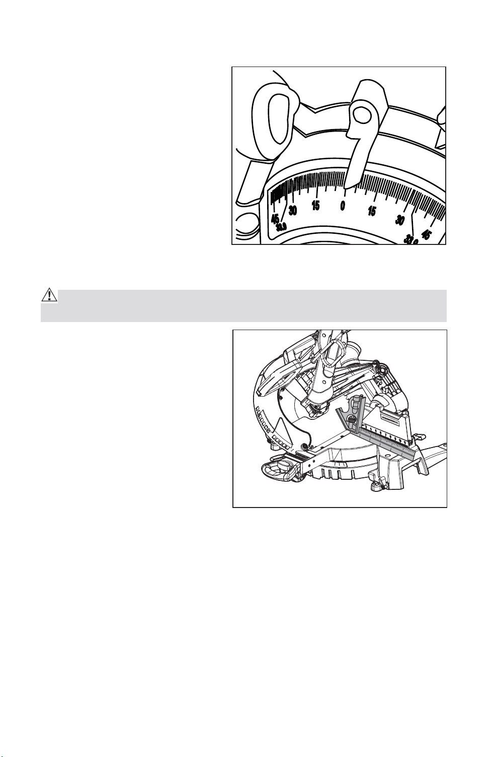
Easy-to-read miter and bevel scales:
Miter angle scale marked in 1° increments, emphasis on every 5°, from 0° to
50° left and 55° right. Positive miter stops at 0°, 15°, 22.5°, 31.6°, and 45° for
exact cuts.
Bevel angle scale marked in 1° increments, emphasis on every 5°, from 0° to
48° left with 33.9° marked. Positive bevel stops at 0˚, 33.9˚ and 45˚ for exact
cuts. The customers need to adjust to 48˚ if necessary.
Miter Table Locking Lever
The miter table locking lever locks the saw table at the desired miter angle,
0° to 50° left or 55° right. The table turns left or right by releasing the miter
lock lever, pressing the detent locking knob and moving the base of the
cutting assembly (which moves the miter table) while holding the miter table
frame secure.
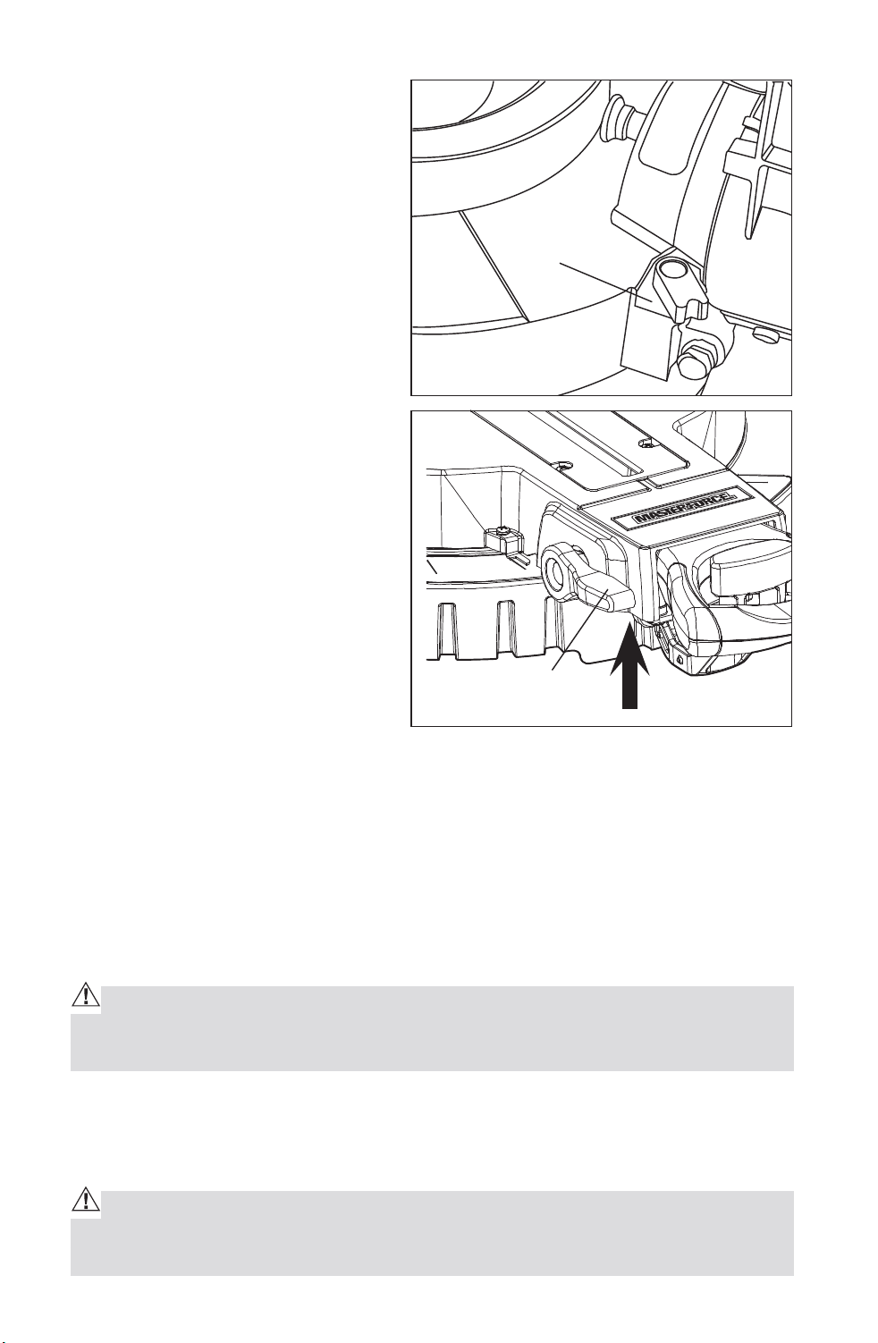
NOTE: The miter table locking lever
might become loose after be used
for a long period. When the miter
table cannot be locked tightly, adjust
the screw to retighten the miter
table locking lever. (Fig.1b)
Bevel Angle Lock Knob
The Bevel Angle lock knob securely
locks your compound miter saw at
the desired bevel angles. Lift up to
unlock, pull out the Head Assembly
Locking Pin and tilt the saw head to set to the desired angle as shown on the
Fig. 1b
Downloaded from www.Manualslib.com
manuals search engine

13
bevel scale. The blade can be positioned at any angle, from a 90° straight cut
(0° on the scale) to a 48° left and right bevel (Fig. 1a). Tighten the bevel lock
knob to secure the saw head.
NOTE: It is necessary to adjust the 48° left and right bevel angle specially.
Miter Fence
The miter fence is in two pieces, with numbered ruler on the left and right
side and a slightly taller left and right side for additional support. Hold the
workpiece securely against the miter fence when making all cuts. Use the
hold down clamp to secure the workpiece whenever possible.
Self-Retracting Lower Blade Guard
The lower blade guard is made of shock-resistant, see-through plastic and
it provides protection from each side of the blade. It retracts over the upper
blade guard as the blade is lowered into the workpiece.
Hold Down Clamp
Mounted on left or right fence or base to securely clamp workpiece.
Carrying Handle/Support Bracket
Use to carry and transport saw.
Downloaded from www.Manualslib.com
manuals search engine
14
ASSEMBLY
MOUNTING THE MITER SAW TO WORK SURFACE (Fig. 2)
To prevent your miter saw from
sliding, falling or tipping during
operation, the saw must be
permanently mounted to a firm,
stable supporting surface, such as
a workbench or piece of plywood.
Four bolt holes have been provided
in the saw base (one in each corner)
for mounting purposes. Each of
these four mounting holes should
be securely bolted using machine
bolts, lock washers and hex nuts
(not included). Bolts should be long enough to fit through the saw base, lock
washers, hex nuts and the thickness of the workbench or plywood. Tighten
all four bolts securely. Position the saw and workbench to allow adequate
room for crosscutting long workpieces. Carefully check the workbench
after mounting the saw to make sure that no movement can occur during
use. If any tipping, sliding or walking is noted, secure the workbench to the
floor before operating. If mounting miter saw to plywood, be sure to clamp
plywood to worktable or bench or place plywood on a flat stable surface
before operating saw.
CAUTION: To reduce the risk of injury, always unplug tool before attach-
ing or removing accessories or making adjustments. Use only specifically
recommended accessories. Others may be hazardous
Fig. 2
Downloaded from www.Manualslib.com
manuals search engine
15
SAWDUST EJECTION PORT
This miter saw comes with a dust
bag to help you keep the work area
clean. The dust bag is ideal for
smaller jobs.
Use a 2 1/2-in. vacuum hose adapter
to hook up your saw to a wet/dry
vacuum (sold separately).
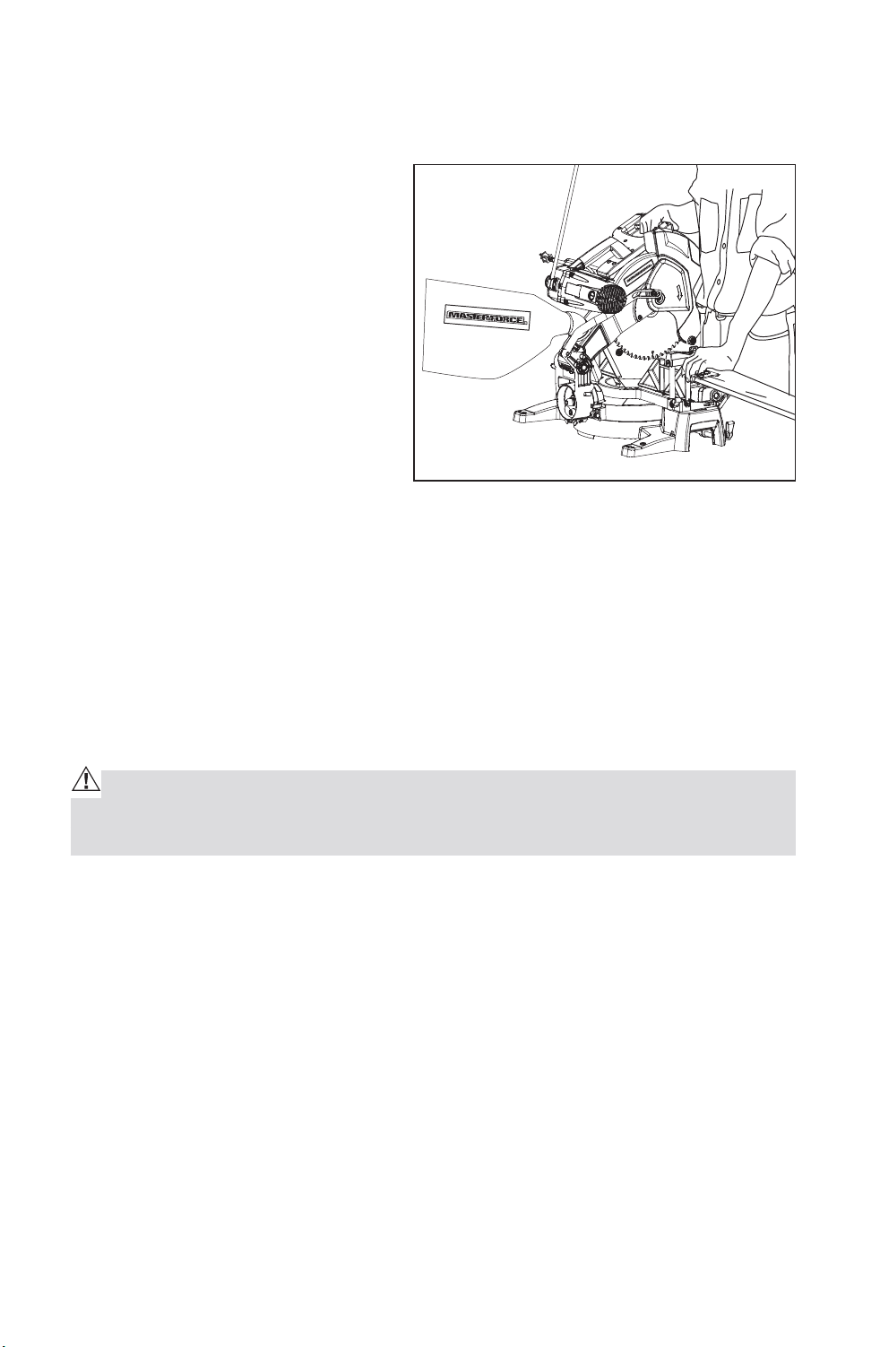
To install dust bag squeeze the
metal collar wings located at the
opening of the dust bag. Place the
dust bag neck opening around the
sawdust ejection port (located on
saw arm, behind upper blade guard)
(Fig. 3) and then release the metal
collar wings. (Fig.3a).
ADJUSTMENTS
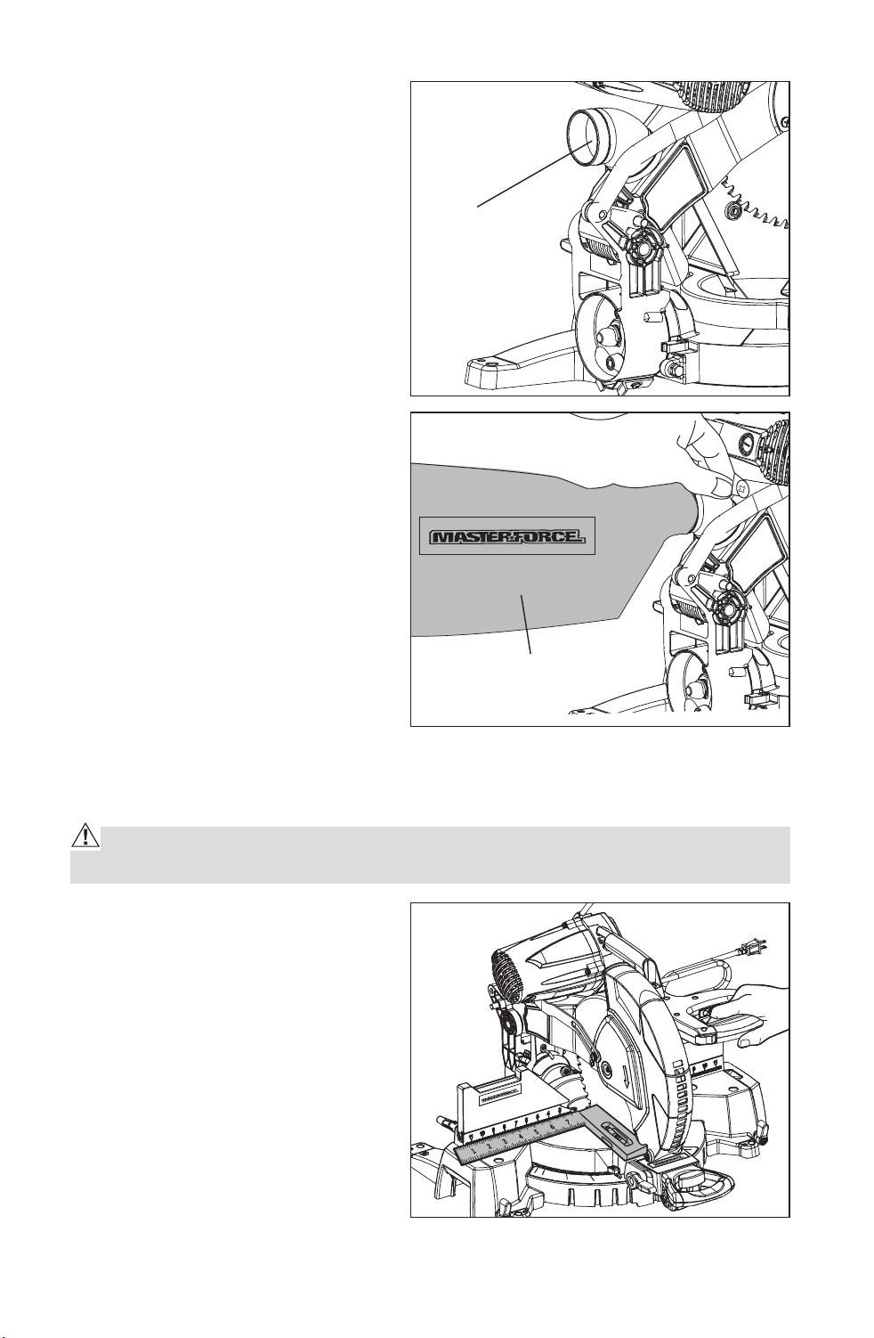
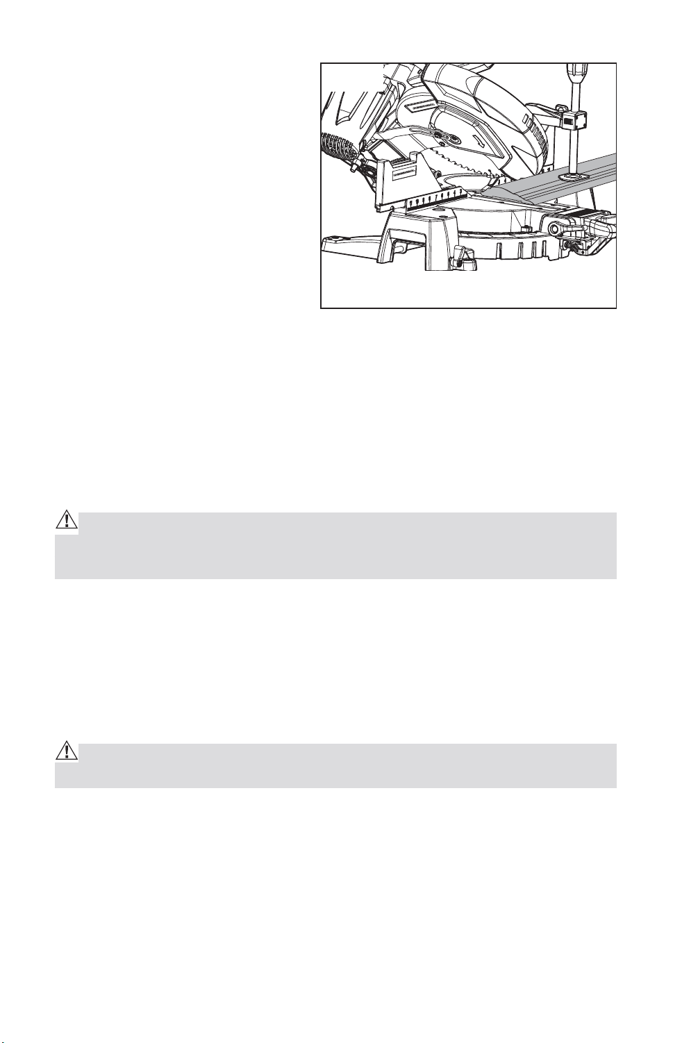
SQUARING THE BLADE TO THE FENCE (Fig. 4)
WARNING: Failure to unplug your saw could result in accidental starting
causing serious injury.
1. Set the bevel and miter angles to
0° degrees.
2. Lower and lock the saw arm into
the “DOWN” position.
3. Using a square lay the heel of
the square against the blade,
and the rule of the square
against the fence.
NOTE: Be sure to rest the square
against the body of the blade and
not against the teeth of the blade.
Fig. 3
Dust Ejection
Port
Dust Bag
Fig. 3a
Fig. 4
Downloaded from www.Manualslib.com
manuals search engine
16
4. If the blade is not 90° to the
fence, unscrew the fence
locking knobs completely
out and remove the fence
extensions.
5. Loosen all hex-head bolts
(Fig.4a). Rotate the fence until
the protractor is flush over its
entire length. Retighten the hex-
head bolts. Remount the fence
extensions.
NOTE: If the saw has not been
used recently, recheck blade squareness to the fence and readjust if
necessary.
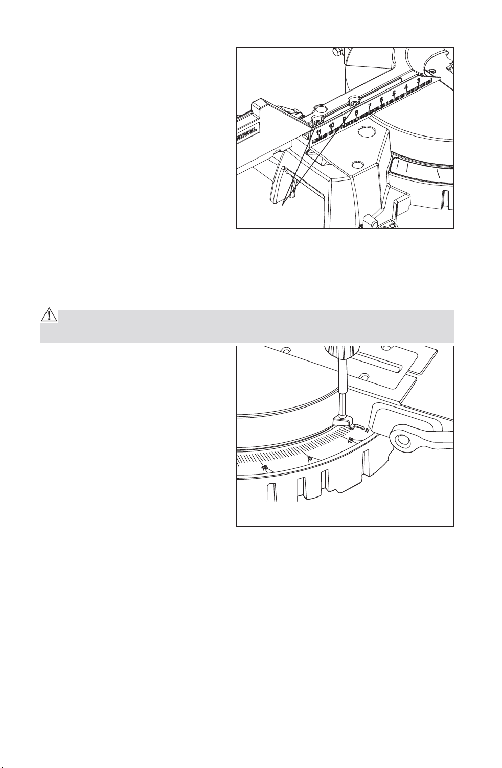
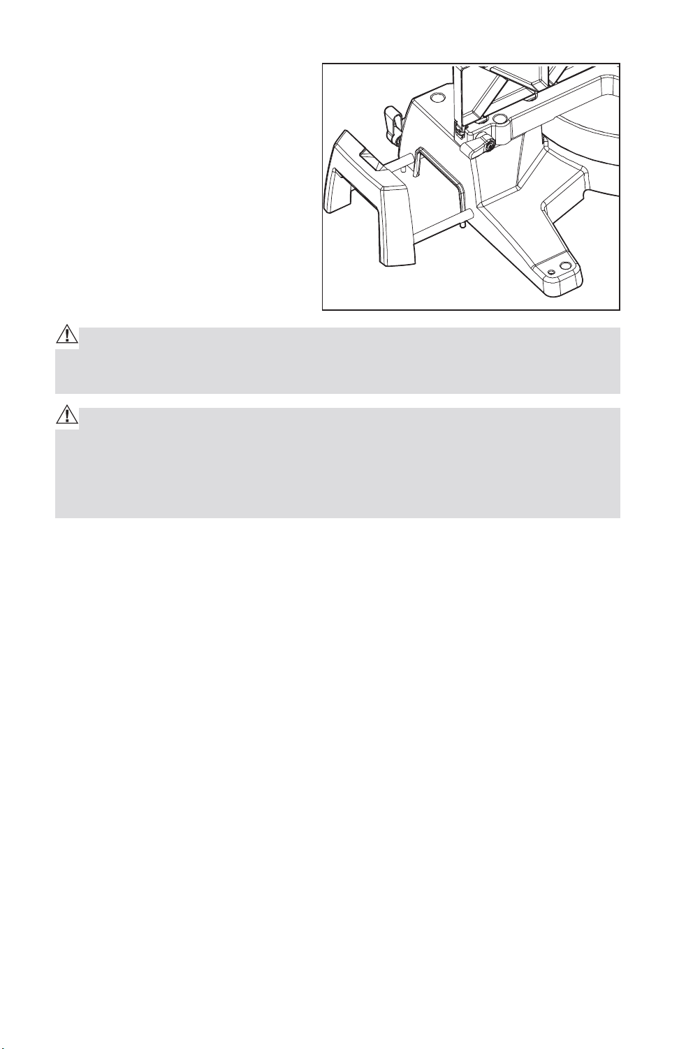
MITER ANGLE INDICATOR ADJUSTMENT (Fig. 5) If Necessary
WARNING: Failure to unplug your saw could result in accidental starting
causing serious injury.
1. Place the miter table at the zero
position, making sure the miter
lock is secured in position.
2. Loosen the miter-angle indicator
screw and adjust the indicator to
the “0” mark on the miter scale
(Fig.5).
3. Tighten the miter angle indicator
screw.
Fig. 4a
Fig. 5
Hex-head bolts
Downloaded from www.Manualslib.com
manuals search engine
17
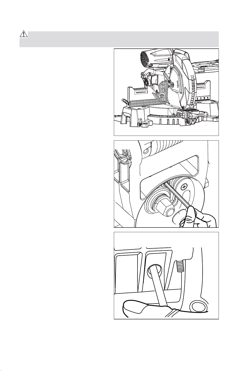
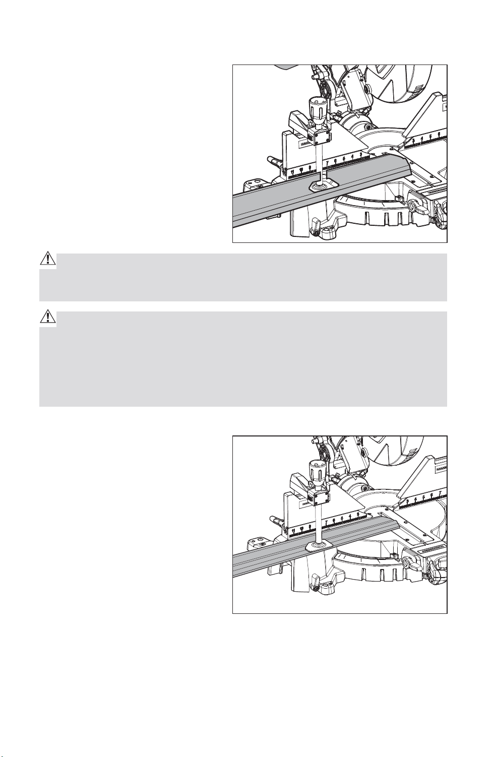
SQUARING THE BLADE TO THE MITER TABLE (Fig. 6, Fig.6b)
WARNING: Failure to unplug your saw could result in accidental starting
causing serious injury.
1. Set the bevel and miter angle
scales to 0°and lock in place.
2. Lower and lock the saw arm into
the “DOWN” position.
3. Place a combination square
on the miter table with the rule
against the table and heel of the
square against the saw blade.
NOTE: Be sure to rest the square
against the body of the blade and
not against the teeth of the blade.
4. Loosen the clamped screw by
hex key as Fig.6 shown.
5. Loosen the bevel lock knob;
loosen the bolts by the hex
wrench as Fig.6b shown. Screw
the adjustment bolt in or out
far enough until the leg of the
protractor is flush with the saw
blade over its entire length.
6. Once the angle is set, tighten
all the bolts and the bevel lock
knob.
Fig. 6
Fig. 6a
Fig. 6b
Blade 90° Square to Miter Table
Downloaded from www.Manualslib.com
manuals search engine
BEVEL ANGLE INDICATOR ADJUSTMENT (Fig. 7) If Necessary
1. Check to see if the bevel angle
indicator is pointing to 0° on the
bevel scale.
2. If the indicator is not on 0°,
loosen the bevel angle indicator
screw, adjust the indicator to
0° on bevel angle scale, and
tighten screw.
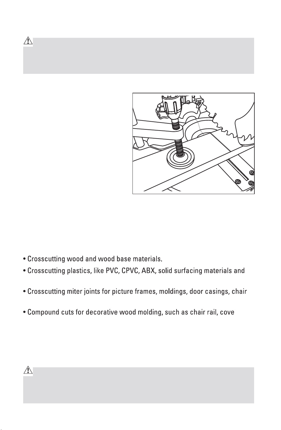
ADJUSTING THE BLADE TO THE MITER TABLE 45° Bevel, 0° MITER (Fig. 8)
WARNING: Failure to unplug your saw could result in accidental starting
causing serious injury.
1. Raise the saw arm.
2. Set the bevel angle scale to 45°.
The miter scale should be on 0°.
Lower and lock the saw arm into
the” DOWN” position.
3. Place a combination square
on the miter table with the rule
against the table and heel of the
square against the saw blade.
NOTE: Be sure to rest the square
against the body of the blade and
not against the teeth of the blade.
4. If the blade is not 45° square with the miter table, perform steps 5 through 7.
5. Loosen the 45°lock nuts by hex wrench.
Fig. 7
Fig. 8
Blade 45° Square to Miter Table
Downloaded from www.Manualslib.com
manuals search engine
19
These setting bolt are to your left
and right as you face the back of
the saw. (Fig.9)
6. Lift up to unlock the bevel angle
lock knob (Fig.10),then adjust
the blade to 45°by adjusting
the setting bolt clockwise or
counterclockwise. You may have
to move the saw arm left or right
by hand while you turning the
setting bolt.
7. Once the angle is set, tighten
the setting bolt and bevel lock
knob.
ADJUSTING THE BEVEL STOP TO
33.9°
NOTE: Adjust the 33.9° bevel angle
only after performing the 0° bevel
angle and pointer adjustment.
To set the 33.9° bevel angle, flip
out the stop pawls. Loosen the
bevel lock knob and tilt the head
to the left. If the pointer does not indicate exactly 33.9°, turn the screw
contacting the Stop Pawl (shown in Fig.9) until the pointer reads 33.9°.
PIVOT ADJUSTMENTS
NOTE: These adjustments were made at the factory and under normal
circumstances do not require re-adjustment.
Saw Arm Travel Pivot Adjustment:
Your saw arm should rise (travel) completely to the up position by itself.
WARNING: To avoid risk of personal injury, if your saw arm does not rise
by itself or if there is play in the pivot joints, have your saw serviced by quali-
fied person before using.
Bevel Pivot Adjustment:
Your miter saw arm should bevel easily by loosening the bevel lock knob and
tilting the saw arm to the left.
WARNING: To avoid risk of personal injury, if movement is tight or if there
is play in the bevel pivot, have your saw serviced by qualified person before
using.
Fig. 9
Fig. 10
Stop Pawl
Bevel angle lock
Downloaded from www.Manualslib.com
manuals search engine
20
OPERATION
CAUTION: ALWAYS make sure the arbor lock button is released so the
blade can rotate freely. MAKE SURE that the locking pin is loose and that the
saw head moves freely up and down. ENSURE that all clamps and locks are
tightly in place and that there is no excessive play in any parts.
HOW TO USE THE DUAL LASER LINE (Fig.11)
1. Mark your workpiece with a
pencil line at the point to be cut.
2. Push the Laser ON/OFF switch
“On” to activate the “bright red
laser line”. Align your pencil line
in the middle of the dual “red
laser lines”.
4. Clamp your workpiece in place
with the hold down clamp.
5. Follow all of the cutting
instructions for the type of cut
you want to make starting on “CROSS CUTTING”
APPLICATIONS
The blade included with this saw is ideal for a wide variety of wood cutting
operations. Use your compound miter saw for the purposes listed below:
other plastics.
rail, shoe and baseboards.
molding and picture frames and other fine joinery.
This tool is NOT recommended for cutting ferrous metals, such as iron, steel,
stainless steel, or alloys of these metals. Cut non-ferrous metals ONLY if you
are under the supervision of an experienced person. Also DO NOT cut stone,
brick, or concrete with this miter saw.
WARNING: BEFORE starting any cutting operation, clamp or bolt your
compound miter saw to a work bench or flat stable work surface. NEVER
operate your miter saw on the floor or in a crouched position. Failure to heed
this warning could result in serious personal injury.
Fig. 11
Downloaded from www.Manualslib.com
manuals search engine
21
SUPPORTING LONG WORKPIECES (Fig.11a)
Long workpieces require extra
supports. The supports should be
placed along the workpiece so it
does not sag. The support should
allow the workpiece to lay flat on
the base of the saw and work table
during the cutting operation. Use
the hold down clamp to secure the
workpiece.
CAUTION: NEVER use another person as an additional support for a work-
piece that is longer or wider than the basic saw table, or to help feed, sup-
port, or pull the workpiece.
WARNING: When using the hold down clamp included or a C-clamp (sold
separately) to secure the workpiece, clamp the workpiece on one side of the
blade ONLY. The workpiece MUST remain unclamped on the other side of
the blade to prevent the blade from binding in the workpiece. The workpiece
binding the blade will cause the motor to stall and cause kickback, resulting
in possible serious injury.
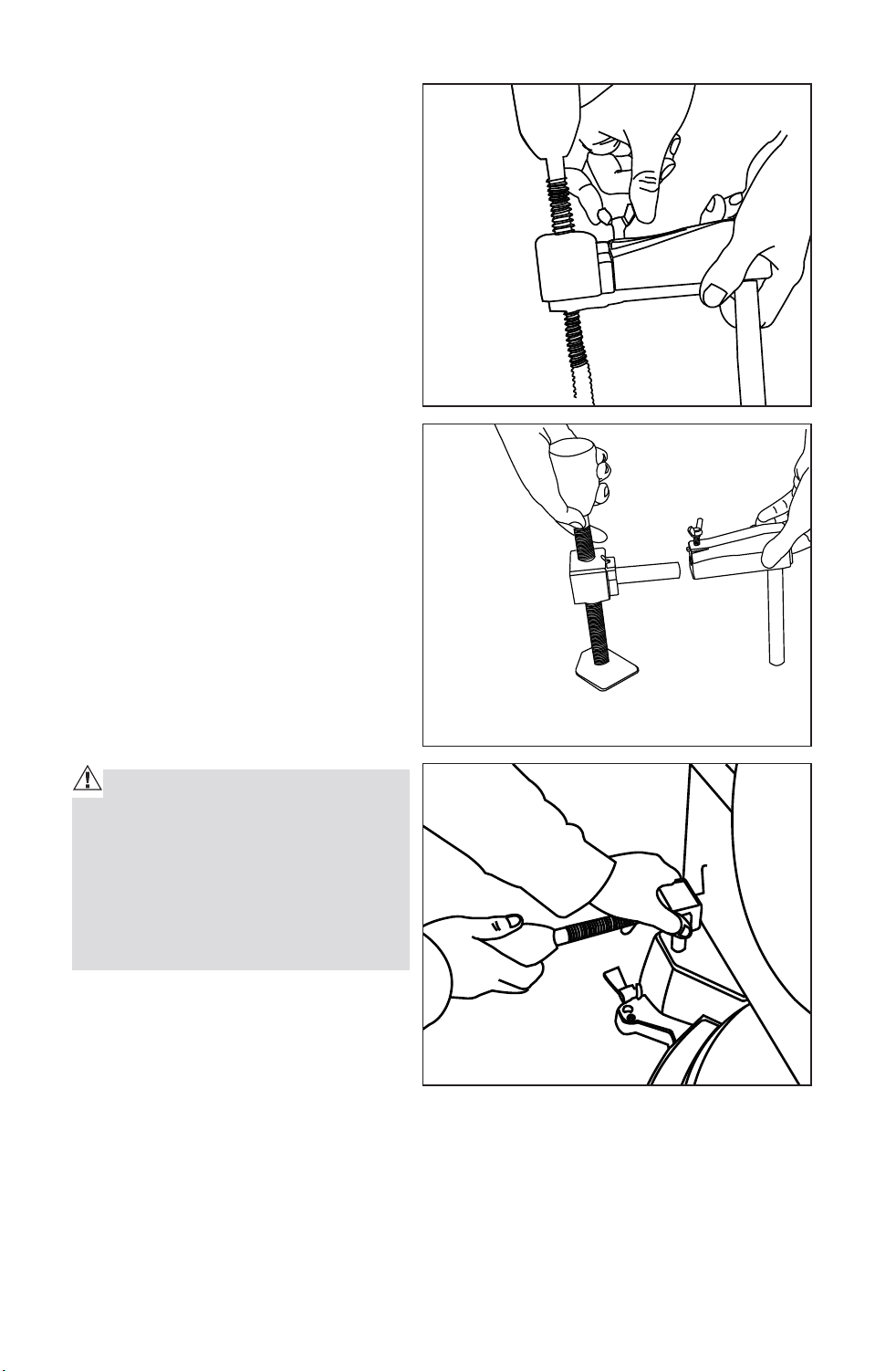
USE THE FENCE AND HOLD DOWN CLAMP (Fig.12)
Align the workpiece flush against
the fence to provide a straight
path for the saw blade. This will
help eliminate the tendency for the
blade teeth to bind.
The hold down clamp fits into
either clamp mounting hole left
or right, on the back of the fence.
Clamp the workpiece to the miter
table securely. The fence and
the hold down clamp should both
be used as a support for miter,
bevel and compound cuts. The hold down clamp can secure the workpiece
horizontally.
Fig. 11a
Fig. 12
Downloaded from www.Manualslib.com
manuals search engine
22
1. Release the tightening knob
counterclockwise, and separate
the two parts. (Fig.12a, Fig12b).
2. Insert the hold down clamp
in the hole as shown, press
the lock button to adjust the
the width according to the
workpiece. (Fig.12c)
3. Tighten the hold down clamp
knob clockwise.
NOTE: When you do the bevel
45°cutting, You must pull to extend
the fence by releasing the fence
locking knob to prevent from
scratching with the saw arm.
CLAMPING WIDE WORKPIECES
When cutting wide workpieces
(such as 2-in. x 8-in. boards) the
boards MUST BE clamped with
the hold down clamp provided or a
C-clamp (sold separately).
CAUTION: Pay attention to the
position of your body and hands.
Proper positioning of your body
and hands when operating the mi-
ter saw will make cutting easier
and safer. NEVER place hands near
the cutting area.
Fig. 12a
Fig. 12b
Fig. 12c
Downloaded from www.Manualslib.com
manuals search engine
23
USING THE MITER SAW
CAUTION: Always hold the cutting handle firmly when making a cut, be-
cause the starting and stopping action of the motor may cause the handle to
move up or down slightly.
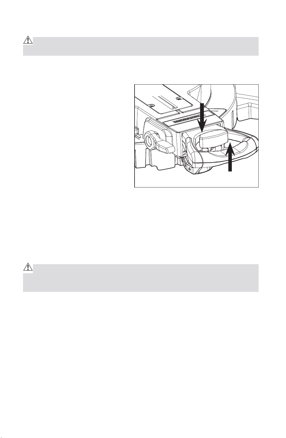
NOTE: Make the ON/OFF trigger
switch childproof. Insert a small
padlock or chain with padlock
through the holes in the ON/OFF
trigger switch, locking the switch
and preventing children or other
unauthorized users from turning
on the saw (Fig. 13).
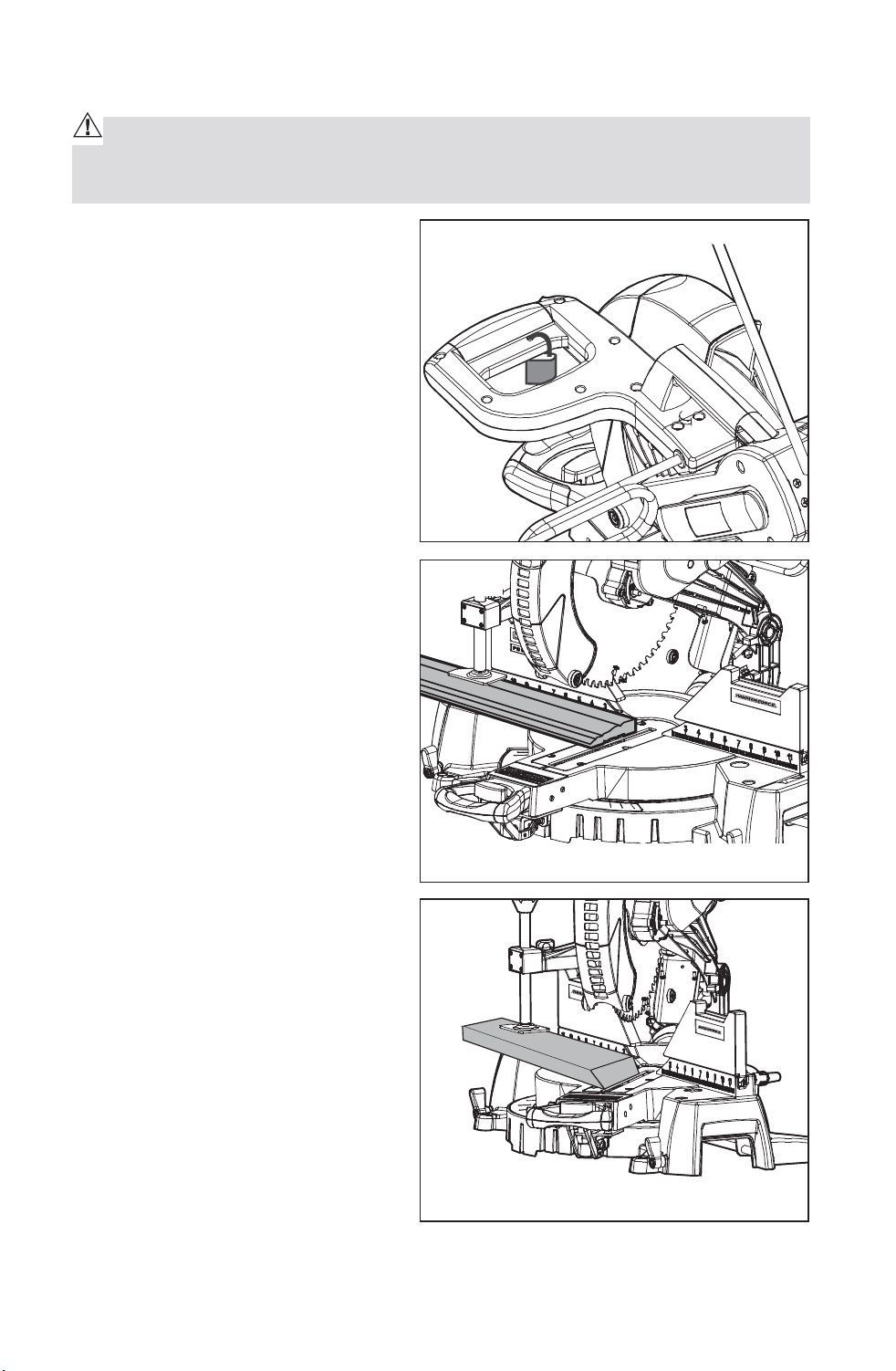
CROSSCUTTING (Fig. 13a and 14)
A crosscut is a cut made across
the grain of the workpiece. A
straight crosscut is a cut made
with the miter table set in the 0°
position (Fig.13a). Miter crosscuts
are made with the miter table set
at some angle, left or right, other
than 0° (Fig.14).
Fig. 13
Fig. 13a
0° Straight Crosscut
45° Miter Crosscut
Fig. 14
Downloaded from www.Manualslib.com
manuals search engine
24
To Crosscut With Your Miter Saw
WARNING: Failure to unplug your saw could result in accidental starting
causing serious injury.
1. Unplug the saw.
2. Lock the saw arm in the down position by pushing in the locking pin.
3. Raise miter lock lever and
release the detent locking knob
by pressing it down to loosen the
miter table. (Fig.14a)
4. Hold the base of the saw arm
firmly and rotate the miter
table on the miter lock lever
by pressing the detent locking
knob while holding the saw base
steady.
5. You can quickly locate 0°, 15°,
22.5°, 31.6° and 45° left or right by the stops or clicks, located and/or color
coded at the above angle settings.
NOTE: When you begin to rotate the miter table to the positive stops on the
miter lock lever, make sure the detent locking knob has been released by
lifting it up.
6. Once you set the miter angle you want, tighten the miter lock lever by
pressing it down.
WARNING: To avoid serious personal injury, ALWAYS tighten the miter
lock lever securely BEFORE making a cut. Failure to do so could result in
movement of the control arm or miter table while making a cut.
7. Release the saw arm by pulling out the locking pin.
8. Place the workpiece flat on the miter table with one edge securely against
the fence. If the board is warped, place the convex side against the fence.
If the concave edge of the board is against the fence, the board could
collapse on the blade at the end of the cut and jam the blade (Figs. 19 and
20).
9. Align your pencil line in the middle of the dual “red laser lines”.
10. Use the hold down clamp to secure workpiece against saw table and
fence.
Fig. 14a
Downloaded from www.Manualslib.com
manuals search engine
25
11. When cutting long workpieces,
pull out extension wing for
extra support for the long
workpieces. (Fig. 14b)
CAUTION: NEVER use another person as an additional support for a work-
piece that is longer or wider than the basic saw table, or to help feed, sup-
port, or pull the workpiece.
WARNING: To avoid serious personal injury, ALWAYS keep your hands
outside the “no hands zone”, as marked on the saw table, which is at least 3
inches from the blade. Also, NEVER perform any cutting operation “freehand”
(i.e. without holding the workpiece against the fence); the blade could grab
the workpiece, causing it to slip and twist.
12. BEFORE turning on the saw, perform a dry run of the cutting operation by
lowering the saw arm to make sure that no problems will occur when the
cut is made.
13. Hold the saw handle and use your middle finger to turn on the laser
switch by pushing it forward.
14. To turn on saw, push the safety lock button in with your thumb while
squeezing the On/Off trigger switch located under the handle (Fig.1a).
Allow several seconds for the blade to reach maximum speed.
15. Slowly lower the blade into and through the workpiece.
16. Release the safety lock and trigger switch and turn off the laser switch.
Allow the saw blade to stop rotating BEFORE raising the blade out of the
workpiece.
NOTE: You can turn on the light LED switch for lighting in the dark areas.
Fig. 14b
Downloaded from www.Manualslib.com
manuals search engine
26
BEVEL CUTTING (Fig. 15)
A bevel cut is a cut made across
the grain of the workpiece with the
blade at an angle to the workpiece.
A straight bevel cut is made
with the miter table set in the 0°
position and the saw arm set at a
bevel angle between 0° and 45°.
To Bevel Cut with Your Miter Saw
1. Unplug the saw.
WARNING: Failure to unplug your saw could result in accidental starting
causing serious injury.
2. Make sure the miter table is at 0° and locked, and check that the miter
table lock lever is down and secured in position.
NOTE: Before you rotate the miter table on the miter lock lever, make sure
the detent locking knob has been released by lifting it up.
WARNING: To avoid serious personal injury, ALWAYS tighten the miter
lock lever securely BEFORE making a cut. Failure to do so could result in
movement of the control arm or miter table while making a cut.
1. Release the saw arm by pulling out the locking pin
2. To make a bevel cut, lift up to unlock the bevel lock knob (Fig. 1a), and pull
the 0° stop bolt out.
3. Tilt the saw arm to the desired bevel angle as shown on the bevel scale.
The blade can be positioned at any angle, from a 90° straight cut (0° on the
scale) to a 48° left and right bevel (Fig. 15).
WARNING: Tighten the bevel lock knob to secure the saw arm in its posi-
tion.
6. Place the workpiece flat on the miter table with one edge securely against
the fence. If the board is warped, place the convex side against the fence. If
the concave edge of the board is against the fence, the board could collapse
on the blade at the end of the cut and jam the blade (Fig. 19 and 20).
7. Align your pencil line in the middle of the dual “red laser lines”.
8. Use the hold down clamp to secure workpiece against saw table and fence
9. When cutting long workpieces, pull out extension wing for extra support
for the long workpieces. (Fig. 14a)
Fig. 15
45°Bevel Cut
Downloaded from www.Manualslib.com
manuals search engine
27
CAUTION: NEVER use another person as an additional support for a work-
piece that is longer or wider than the basic saw table, or to help feed, sup-
port, or pull the workpiece.
WARNING: To avoid serious personal injury, ALWAYS keep your hands
outside the “no hands zone”, as marked on the saw table, which is at least 3
inches from the blade. Also, NEVER perform any cutting operation “freehand”
(i.e. without holding the workpiece against the fence); the blade could grab
the workpiece, causing it to slip and twist.
10. BEFORE turning on the saw, perform a dry run of the cutting operation by
lowering the saw arm to make sure that no problems will occur when the
cut is made.
11. Hold the saw handle and use your middle finger to turn on the laser
switch by pushing it forward.
12. To turn on saw, push the safety lock button in with your thumb while
squeezing the On/Off trigger switch located under the handle (Fig.1a).
Allow several seconds for the blade to reach maximum speed.
13. Slowly lower the blade into and through the workpiece.
14. Release the safety lock and trigger switch, and turn off the laser switch.
Allow the saw blade to stop rotating BEFORE raising the blade out of the
workpiece.
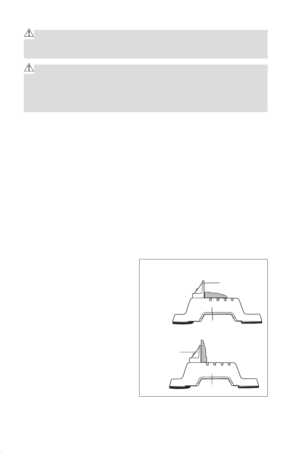
CUTTING BASE MOLDING (Fig. 16)
Base moldings and many other
moldings can be cut on a miter
saw. The setup of the saw depends
on base molding characteristics
and applications, as shown.
Perform practice cuts on scrap
materials to achieve best result.
1. Always make sure moldings rest
firmly against fence and table
(Fig. 16). Use hold-down clamp
provided, crown molding vise,
or C-clamps and place tape on
the area being clamped to avoid
marks on the workpiece.
2. Reduce splintering by taping the cut area prior to making the cut. Mark the
cut line directly on the tape.
Fig. 16
Molding lying flat on miter
table(before clamping)
Fence
Fence
Miter at 0°,
Bevel at 45°
Miter at 0°,
Bevel at 45°
Miter Saw
Miter Saw
Molding standing up against fence
(before clamping)
Downloaded from www.Manualslib.com
manuals search engine
28
3. Splintering typically happens due to incorrect blade style, dull blade,
thinness of workpiece, or improperly dried wood.
NOTE: Always perform a dry run cut so you can determine if the operation
being attempted is possible before power is applied to miter saw.
4. Place the workpiece flat on the miter table with one edge securely against
the fence. If the board is warped, place the convex side against the fence. If
the concave edge of the board is against the fence, the board could collapse
on the blade at the end of the cut and jam the blade (Fig. 19 and 20).
5. Align your pencil line in the middle of the dual “red laser lines”.
6. Use the hold down clamp to secure workpiece against saw table and fence.
7. When cutting long workpieces, pull out extension wing for extra support
for the long workpieces. (Fig. 14a)
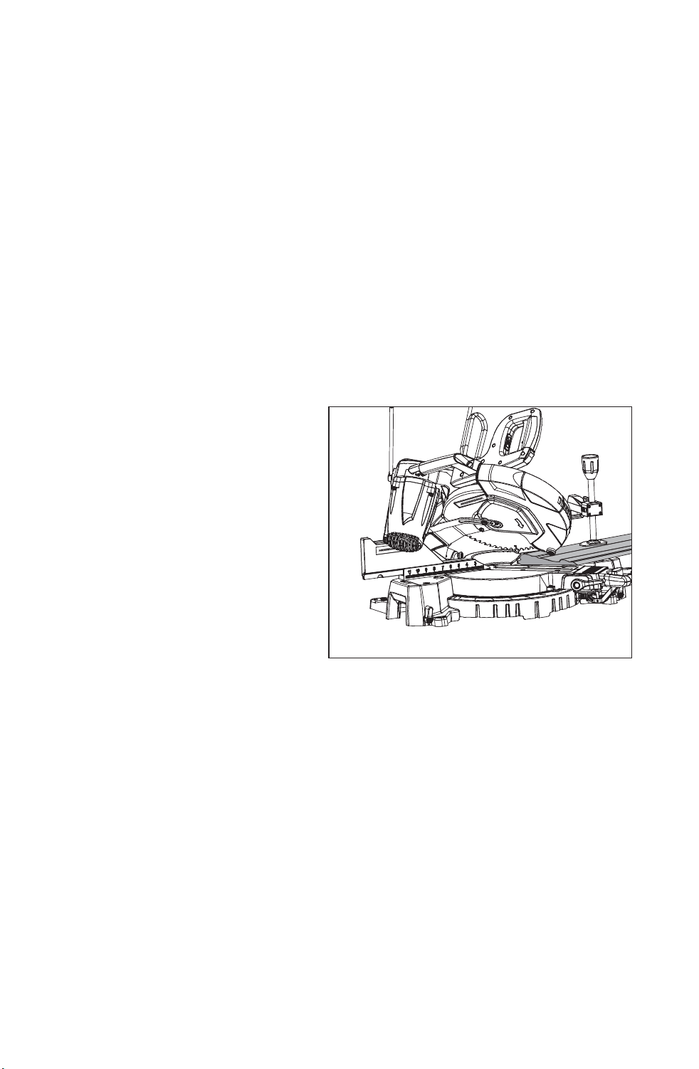
COMPOUND MITER CUTTING (Fig. 17)
A compound miter cut is a cut
made using a miter angle and a
bevel angle at the same time. This
type of cut is used for decorative
moldings, picture frames and
other fine joinery. To make this
type of cut, the miter table must be
rotated to the correct miter angle
and the saw arm must be tilted to
the correct bevel angle. ALWAYS
take special care when making
compound miter cuts due to the
interaction of the two angle settings. Adjustments of miter and bevel settings
are dependent on one another. Each time you adjust the miter setting, you
change the effect of the bevel setting. Also, each time you adjust the bevel
setting, you change the effect of the miter setting.
It may take several settings to obtain the desired cut. The first angle setting
should be checked after setting the second angle, since adjusting the second
angle affects the first.
Once the two correct settings for a particular cut have been obtained,
ALWAYS make a test cut in scrap material BEFORE making a finish cut in
good material.
Fig. 17
Compound 45° Bevel, 45° Miter Cut
Downloaded from www.Manualslib.com
manuals search engine

29
To Make a Compound Miter Cut with your Miter Saw
1. Unplug the saw.
WARNING: Failure to unplug your saw could result in accidental starting
causing serious injury.
2. Release the saw arm by pulling out the locking pin.
3. Raise miter lock lever and pressing the detent locking knob to loosen the
miter table.
4. Hold the base of the saw arm firmly and rotate the miter table on the miter
lock lever by pressing the detent locking knob while holding the saw base
steady.
5. You can quickly locate 0°, 15°, 22.5°, 31.6° and 45° left or right by the stops
or clicks, located and/or color coded at the above angle settings.
6. Once you have the miter table setting you want, tighten the miter lock lever
by pressing it down.
WARNING: To avoid serious personal injury, ALWAYS tighten the miter
lock lever securely BEFORE making a cut. Failure to do so could result in
movement of the control arm or miter table while making a cut.
7. To set the bevel angle, loosen the bevel lock knob (Fig. 1a), turn
counterclockwise, pulling the 0°stop bolt out.
8. Tilt the saw arm to the desired bevel angle as shown on the bevel scale.
Bevel angles can be set from 0° to 48° left and right bevel.
9. Once the saw arm has been set at the desired angle, securely tighten the
bevel lock knob.
10. Place the workpiece flat on the miter table with one edge securely
against the fence. If the board is warped, place the convex side against
the fence. If the concave edge of the board is against the fence, the
board could collapse on the blade at the end of the cut and jam the blade
(Figs. 19, 20).
11. Align your pencil line in the middle of the dual “red laser lines”.
12. Use the hold down clamp to secure workpiece against saw table and
fence.
13. When cutting long workpieces, pull out extension wing for extra support
for the long workpieces. (Fig. 14a)
CAUTION: NEVER use another person as an additional support for a work-
piece that is longer or wider than the basic saw table, or to help feed, sup-
port, or pull the workpiece.
Downloaded from www.Manualslib.com
manuals search engine

30
WARNING: To avoid serious personal injury, ALWAYS keep your hands
outside the “no hands zone”, as marked on the saw table, which is at least 3
inches from the blade. Also, NEVER perform any cutting operation “freehand”
(i.e. without holding the workpiece against the fence); the blade could grab
the workpiece, causing it to slip and twist.
14. Make sure that there will be no obstructions to interfere with when
making the cut.
15. Hold the saw handle and use your middle finger to turn on the laser
switch by pushing it forward
16. To turn on saw, push the safety lock button in with your thumb while
squeezing seconds for the blade to reach maximum speed.
17. Slowly lower the blade into and through the workpiece.
NOTE: You can turn on the light LED switch for lighting in the dark areas.
18. Release the safety lock and trigger switch, and turn off the laser switch.
Allow the saw blade to stop rotating BEFORE raising the blade out of the
workpiece.
CUTTING COMPOUND MITERS
To help you to make the correct settings, use the compound angle setting
chart below. Since compound cuts are the most difficult to accurately obtain,
plan carefully and make trial cuts in scrap material prior to making your
required cut.
Downloaded from www.Manualslib.com
manuals search engine

31
Each B (Bevel) and M (Miter) Setting is listed to the closest 0.005°
COMPOUND-ANGLE SETTINGS FOR POPULAR STRUCTURES
*Pitch of Side = Angle of side from vertical. Example:
PITCH
NUMBER OF SIDES
OF SIDE
3 4 5 6 7 8 9
M-45.00
o
M-36.00
o
M-30.00
o
M-25.71
o
M-22.50
o
M-20.00
o
M-18.00
o
B- 0.00
o
B- 0.00
o
B- 0.00
o
B- 0.00
o
B- 0.00
o
B- 0.00
o
B- 0.00
o
M-44.89
o
M-35.90
o
M-29.91
o
M-25.63
o
M-22.42
o
M-19.93
o
M-17.94
o
B- 3.53
o
B- 2.94
o
B- 2.50
o
B- 2.17
o
B- 1.91
o
B- 1.71
o
B- 1.54
o
M-44.56
o
M-35.58
o
M-29.62
o
M-25.37
o
M-22.19
o
M-19.72
o
M-17.74
o
B- 7.05
o
B- 5.86
o
B- 4.98
o
B- 4.32
o
B- 3.81
o
B- 3.40
o
B- 3.08
o
M-44.01
o
M-35.06
o
M-29.15
o
M-24.95
o
M-21.81
o
M-19.37
o
M-17.42
o
B-10.55
o
B- 8.75
o
B- 7.44
o
B- 6.45
o
B- 5.68
o
B- 5.08
o
B- 4.59
o
M-43.22
o
M-34.32
o
M-28.48
o
M-24.35
o
M-21.27
o
M-18.88
o
M-16.98
o
B-14.00
o
B-11.60
o
B- 9.85
o
B- 8.53
o
B- 7.52
o
B- 6.72
o
B- 6.07
o
M-42.19
o
M-33.36
o
M-27.62
o
M-23.35
o
M-20.58
o
M-18.26
o
M-16.41
o
B-17.39
o
B-14.38
o
B-12.20
o
B-10.57
o
B- 9.31
o
B- 6.72
o
B- 7.50
o
M-40.89
o
M-32.18
o
M-26.57
o
M-22.64
o
M-19.73
o
M-17.50
o
M-15.72
o
B-20.70
o
B-17.09
o
B-14.48
o
B-12.53
o
B-11.03
o
B- 9.85
o
B- 8.89
o
M-39.32
o
M-30.76
o
M-25.31
o
M-21.53
o
M-18.74
o
M-16.60
o
M-14.90
o
B-23.93
o
B-19.70
o
B-16.67
o
B-14.41
o
B-12.68
o
B-11.31
o
B-10.21
o
M-37.45
o
M-29.10
o
M-23.86
o
M-20.25
o
M-17.60
o
M-15.58
o
M-13.98
o
B-27.03
o
B-22.20
o
B-18.75
o
B-16.19
o
B-14.24
o
B-12.70
o
B-11.46
o
M-35.26
o
M-27.19
o
M-22.21
o
M-18.80
o
M-16.32
o
M-14.43
o
M-12.94
o
B-30.00
o
B-24.56
o
B-20.70
o
B-17.87
o
B-15.70
o
B-14.00
o
B-12.62
o
M-32.73
o
M-25.03
o
M-20.36
o
M-17.20
o
M-14.91
o
M-13.17
o
M-11.80
o
B-32.80
o
B-26.76
o
B-22.52
o
B-19.41
o
B-17.05
o
B-15.19
o
B-13.69
o
M-29.84
o
M-22.62
o
M-18.32
o
M-15.44
o
M-13.36
o
M-11.79
o
M-10.56
o
B-35.40
o
B-28.78
o
B-24.18
o
B-20.82
o
B-18.27
o
B-16.27
o
B-14.66
o
M-26.57
o
M-19.96
o
M-16.10
o
M-13.54
o
M-11.70
o
M-10.31
o
M- 9.23
o
B-37.76
o
B-30.60
o
B-25.66
o
B-22.07
o
B-19.35
o
B-17.23
o
B-15.52
o
M-22.91
o
M-17.07
o
M-13.71
o
M-11.50
o
M- 9.93
o
M- 8.74
o
M- 7.82
o
B-39.86
o
B-32.19
o
B-26.95
o
B-23.16
o
B-20.29
o
B-18.06
o
B-16.26
o
M-18.88
o
M-13.95
o
M-11.17
o
M- 9.35
o
M- 8.06
o
M- 7.10
o
M- 6.34
o
B-41.64
o
B-33.53
o
B-28.02
o
B-24.06
o
B-21.08
o
B-18.75
o
B-16.88
o
M-14.51
o
M-10.65
o
M- 8.50
o
M- 7.10
o
M- 6.12
o
M- 5.38
o
M- 4.81
o
B-43.08
o
B-34.59
o
B-28.88
o
B-24.78
o
B-21.69
o
B-19.29
o
B-17.37
o
M- 9.85
o
M- 7.19
o
M- 5.73
o
M- 4.78
o
M- 4.11
o
M- 3.62
o
M- 3.23
o
B-44.14
o
B-35.37
o
B-29.50
o
B-25.30
o
B-22.14
o
B-19.68
o
B-17.72
o
M- 4.98
o
M-3.62
o
M- 2.88
o
M- 2.40
o
M- 2.07
o
M- 1.82
o
M- 1.62
o
B-44.78
o
B-35.84
o
B-29.87
o
B-25.61
o
B-22.41
o
B-19.92
o
B-17.93
o
M- 0.00
o
M- 0.00
o
M- 0.00
o
M- 0.00
o
M- 0.00
o
M- 0.00
o
M- 0.00
o
B-45.00
o
B-36.00
o
B-30.00
o
B-25.71
o
B-22.50
o
B-20.00
o
B-18.00
o
75
o
80
o
85
o
90
o
55
o
60
o
65
o
70
o
0
o
5
o
10
o
15
o
40
o
45
o
50
o
20
o
25
o
30
o
35
o
Downloaded from www.Manualslib.com
manuals search engine
32
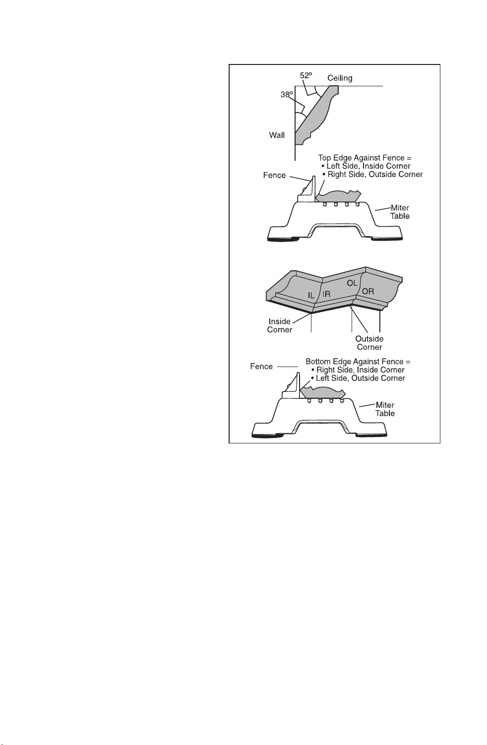
CUTTING CROWN MOLDING (Fig. 18)
Your miter saw is ideal for cutting
crown molding. In order to fit
properly, crown molding must be
compound-mitered with extreme
accuracy. To fit flat against the
ceiling and wall, the sum of the
angles of the crown molding’s two
connecting surfaces must equal
90°(Fig.18)
Most crown molding has a high top
rear spring angle (the section that
fits flat against the ceiling) of 52°
and a bottom rear spring angle (the
section that fits flat against the
wall) of 38°
In order to accurately cut crown
molding for a 90° inside or outside
corner, lay the molding with its
broad back surface flat on the
miter table and against the fence
(Fig.18).
When setting the bevel and miter
angles for compound miter cuts,
remember that the settings are
interdependent; changing one changes the other, as well.
Keep in mind that since it is very easy for the angles of crown molding to shift
slightly, all settings should be tested on scrap molding. Also, most walls do
not have angles of precisely 90°, therefore, you will need to fine tune your
settings.
When cutting crown molding, the bevel angle should be set at 33.9°, the miter
angle should be set at 31.6° either left or right, depending upon the desired
cut for the application. See the following table for correct angle setting and
correct positioning of the crown molding on the miter table.
The settings in the table below can be used for cutting all standard (U.S.)
crown molding with 52 °And 38 ° spring angles. The crown molding is placed
flat on the miter table, using the compound features of your miter saw.
Always uses the hold down clamp, and place tape on the area being clamped
to avoid marks on the workpiece.
Fig. 18
Downloaded from www.Manualslib.com
manuals search engine

33
COMPOUND BEVEL /MITER SETTINGS
Key Bevel
Setting
Miter
Setting
Type of cut
IL 33.9° Left 31.6°Right Inside corner - Left side
1. Position top of molding against fence.
2. Miter table set at RIGHT 31.6°
3. LEFT side is finished piece.
IR 33.9° Right 31.6°Left Inside corner - Right side
1. Position top of molding against fence.
2. Miter table set at LEFT 31.6°
3. Right side is finished piece
OL 33.9° Right 31.6°Left Outside corner - Left side
1. Position top of molding against fence.
2. Miter table set at LEFT 31.6°
3. LEFT side is finished piece
OR 33.9° Left 31.6°Right Outside corner - Right side
1. Position top of molding against fence.
2. Miter table set at RIGHT 31.6°
3. RIGHT side is finished piece.
Downloaded from www.Manualslib.com
manuals search engine
34
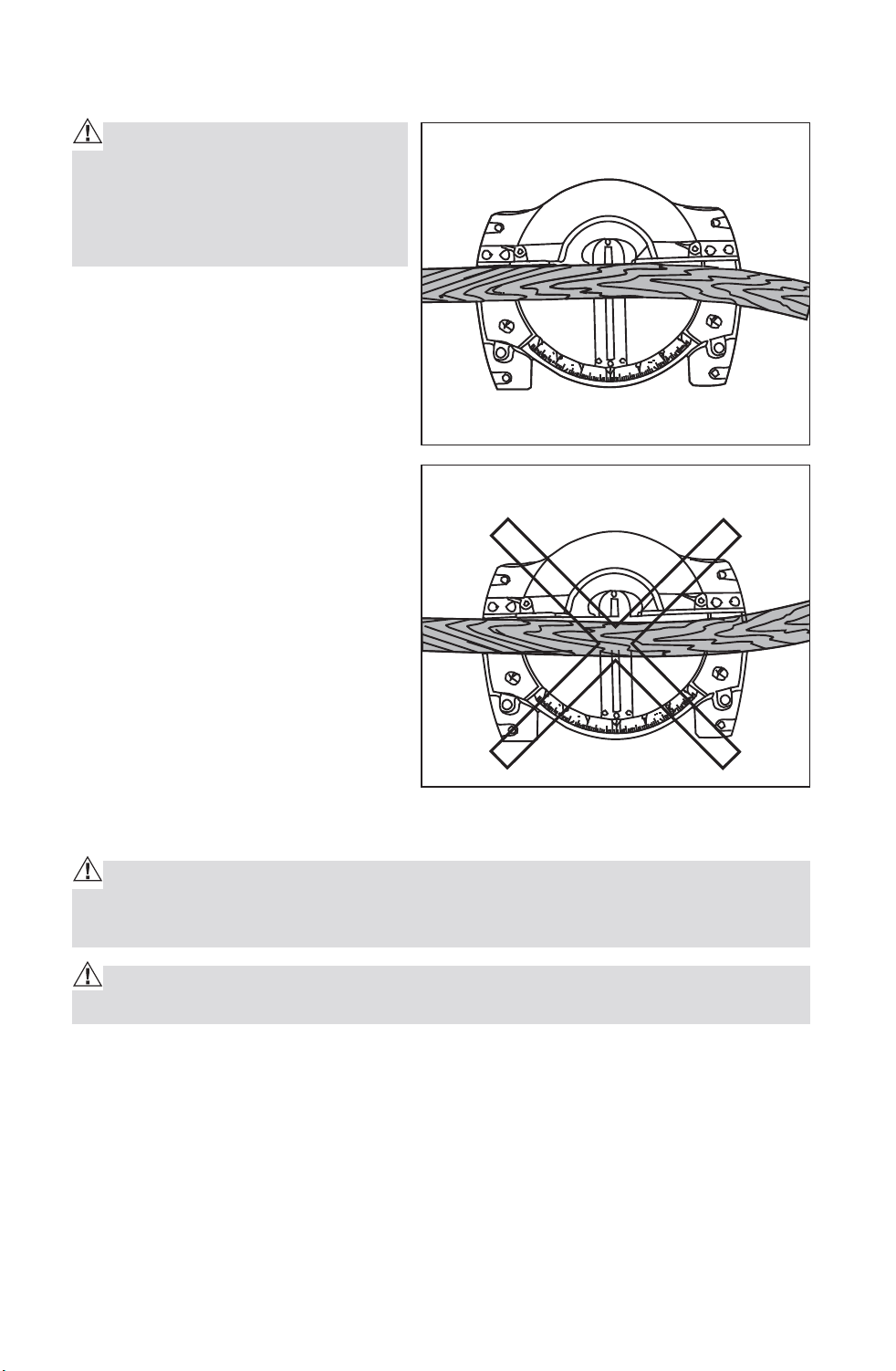
CUTTING WARPED MATERIAL (Fig.19 and 20)
WARNING: To avoid kickback
and to avoid serious personal in-
jury NEVER position the concave
side of bowed or warped material
against the fence.
When cutting warped material,
BE CERTAIN that the material to
be cut is positioned on the miter
table with the convex side against
the fence, as shown (Fig. 19). If the
warped material is positioned the
wrong way, (Fig. 20), it will pinch
the blade near the end of the cut.
MAINTENANCE
WARNING: To ensure safety and reliability, all repairs - with the excep-
tion of the externally accessible brushes - should be performed by a qualified
service technician.
WARNING: For your safety, ALWAYS turn off switch and unplug miter saw
from the power source before performing any maintenance or cleaning.
Electric tools are subject to accelerated wear and possible premature
failure when they are used to work on fiber glass boats and sports cars,
wallboard, spackling compounds or plaster. The chips and grindings from
these materials are highly abrasive to electrical tool parts, such as bearings,
brushes, commutator, etc. Consequently, it is not recommended that this tool
be used for extended work on any fiberglass material, wallboard, spackling
compound or plaster. During any use on these materials, it is extremely
important that the tool is cleaned frequently by blowing with an air jet.
Fig. 19 Top View
Wright
Wrong
Fig. 20
Downloaded from www.Manualslib.com
manuals search engine
35
WARNING: Always wear safety goggles or safety glasses with side
shields during power tool operations, or when blowing dust. If operation is
dusty, also wear a dust mask.
ROUTINE MAINTENANCE
WARNING: DO NOT at any time let brake fluid, gasoline, petroleum-based
products, penetrating oils, etc. come in contact with plastic parts. Chemicals
can damage, weaken or destroy plastic, which may result in serious per-
sonal injury.
Periodic maintenance allows for long life and trouble-free operation. A
cleaning, lubrication and maintenance schedule should be maintained. As a
common preventive maintenance practice, follow these recommended steps:
1. When work has been completed, clean the tool to allow smooth
functioning of the tool over time.
2. Use clean damp cloths to wipe the tool.
3. Check the state of all electrical cables.
4. Keep the motor air openings free from oil, grease and sawdust or
woodchips and store tool in a dry place.
5. Be certain that all moving parts are well lubricated, particularly after
lengthy exposure to damp and/or dirty conditions.
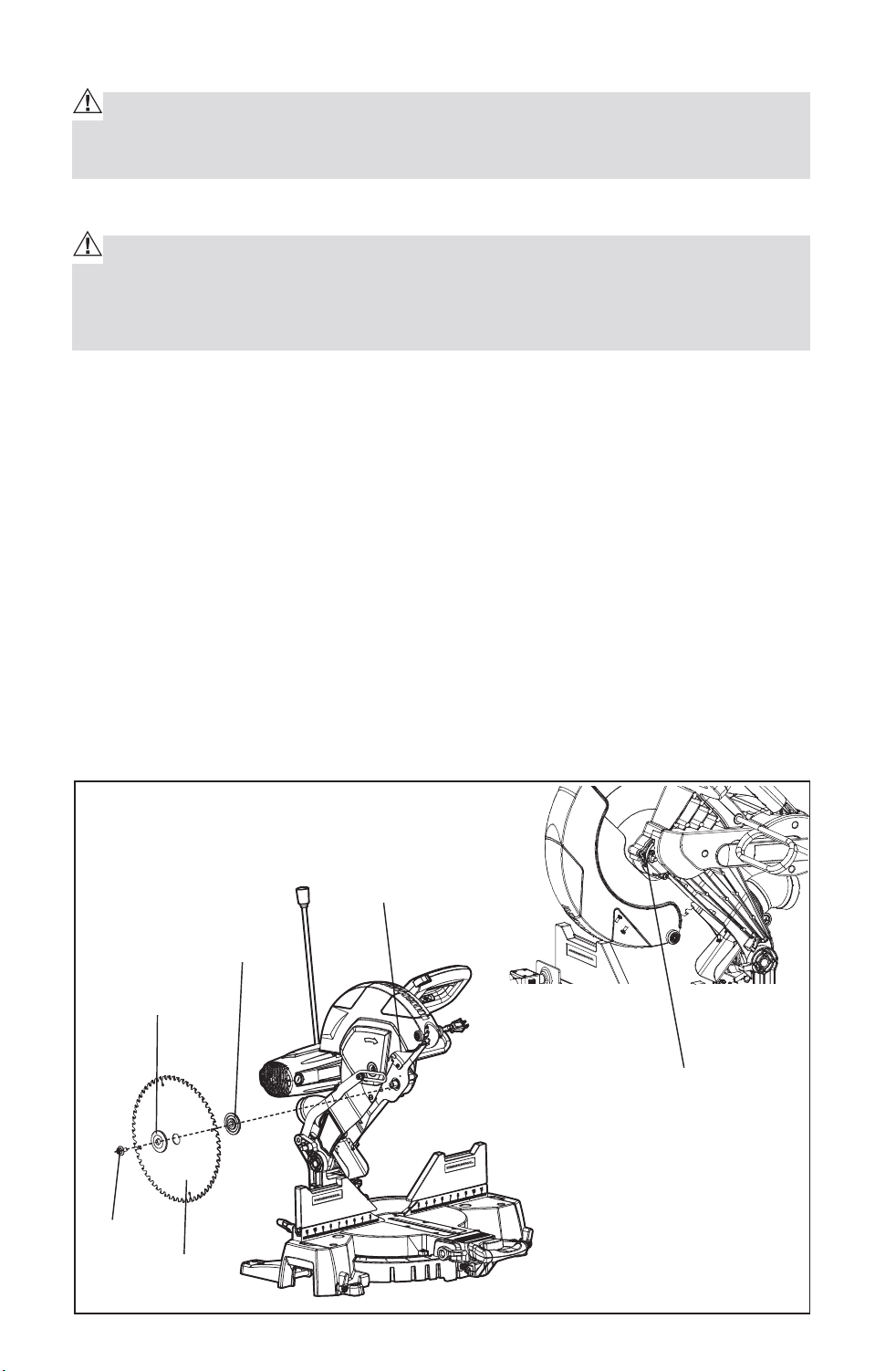
CHANGING THE BLADE (Fig. 21)
Fig. 21
Outer Flange
Inner Flange
Arbor Screw
Guark
Arbor Lock Button
Arbor
Screw
Blade
Downloaded from www.Manualslib.com
manuals search engine

36
WARNING: To prevent personal injury, ALWAYS disconnect the plug from
power source BEFORE assembling parts, making adjustments or changing
blades.
WARNING: Be sure to wear protective work gloves while handling a saw
blade. The blade can injure unprotected hands.
1. Raise the saw arm.
2. Use Phillips screwdriver, loosen but do not remove screw on the arbor
screw guard by turning counterclockwise.
3. Rotate arbor guard to expose the arbor.
4. Press and hold arbor lock button while loosening and removing the left-
hand-thread arbor screw by turning clockwise with the wrench included.
5. Lift and hold up the lower blade guard.
6. Remove the outer blade flange.
7. Remove blade from arbor. Wipe the flanges and arbor to remove dust and
debris.
8. Take the new blade and match the direction of the arrow on it with the
direction of the arrow on the upper blade guard. Make sure the blade teeth
are pointing downward. Install the blade by sliding the blade into the upper
blade guard and placing the blade up and onto the arbor.
Note: inner flange will already be on the arbor.
9. Replace the outer blade flange, making sure the flat side of the flange is
against the blade. Replace the arbor screw and tighten counterclockwise
with the supplied wrench while holding in the arbor lock button until lock
engages, then tightening the arbor screw securely.
10. Rotate the arbor guard into position and securely tighten its screw by
turning clockwise with the Phillips screwdriver.
11. Lower the saw arm and check the clearance between the blade and the
miter table. The blade should rotate freely.
CAUTION: ALWAYS make sure the spindle lock button is released so the
blade can rotate freely. MAKE SURE that the locking pin is loose and that the
saw head moves freely up and down. ENSURE that all clamps and locks are
tightly in place and that there is no excessive play in any parts.
Downloaded from www.Manualslib.com
manuals search engine
37
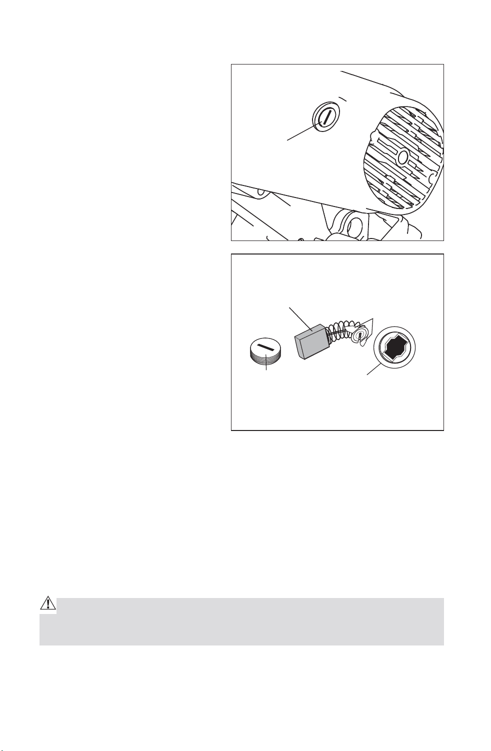
REPLACEMENT OF CARBON BRUSHES (Fig. 22, 23)
The factory installed carbon
brushes in the motor assembly
inspect it regularly by unplugging
tool. Keep brushes clean and
sliding freely in their guides.
Always replace a used brush in the
same orientation in the holder as it
was prior to its removal.
1. First unplug the saw before
inspecting or replacing brushes.
2. Replace both carbon brushes
when either has less than 1/4-in.
length of carbon remaining, or if
the spring or wire is damaged or
burned.
3. Using a slotted screwdriver,
remove the black plastic cap on
each side of the motor housing
(Fig. 22), and carefully withdraw
the spring-loaded brush
assemblies. Keep brushes clean
and sliding freely in their guide
channels.
NOTE: To reinstall the same brushes, make sure the brushes go back in the
same way they came out. This will avoid a break-in period.
4. Insert new brush assemblies into guide channels, with the carbon part
going in first, being certain to fit the two metal “ears” into their slots in the
channel (Fig. 23).
5. Remember to replace both end caps after inspecting or servicing brushes.
Tighten the caps snugly, but do not over-tighten. The saw should be
allowed to “RUN IN” (run at no-load without a blade) for 5 minutes before
use, to seat the new brushes properly.
WARNING: WHILE “RUNNING IN”, DO NOT TIE, TAPE, OR OTHERWISE
LOCK THE TRIGGER SWITCH “ON”! HOLD THE TRIGGER SWITCH “ON” BY
HAND ONLY!
Fig. 22
Plastic Cap
Plastic Cap
Brush Opening
Ears
Carbon Brush
Fig. 23
Downloaded from www.Manualslib.com
manuals search engine

38
LOWER BLADE GUARD
WARNING: DO NOT use the saw without the lower blade guard. The low-
er blade guard is attached to the saw for your protection. Should the lower
blade guard become damaged, do not use the saw until the damaged guard
has been replaced. Check the lower blade guard regularly; making certain
that it is in proper working order.
CAUTION: When cleaning the lower blade guard, unplug the saw from the
power source receptacle to avoid unexpected startup.
NOTE: Do not use solvents on the guard, as they may cause any plastic parts
to become “cloudy” or brittle.
SAWDUST
Periodically, sawdust will accumulate under the worktable and base. This
could cause difficulty in the movement of the worktable when setting up a
miter cut. Frequently blow out or vacuum up the sawdust.
WARNING: Always wear safety goggles or safety glasses with side
shields during power tool operations, or when blowing dust. If operation is
dusty, also wear a dust mask.
LUBRICATION
All the motor bearings in this tool are lubricated with a sufficient amount
of high-grade lubricant for the life of the unit, under normal operating
conditions; therefore, no further lubrication is required.
SERVICE OF LASER GUIDE
Use a soft paintbrush or similar device to remove all sawdust and debris.
(Compressed air contains fine oil droplet which adhere to the lens; you
should therefore not blow out the lens with compressed air)
Downloaded from www.Manualslib.com
manuals search engine

39
TROUBLE SHOOTING
PROBLEM PROBLEM CAUSE SUGGESTED CORRECTIVE
ACTION
Brake does not
stop blade within
5 seconds.
Motor brushes not sealed
or lightly sticking
Inspect/clean/
replace brushes See
MAINTENANCE section
Motor brake overheated
from use of defective or
wrong size blade or rapid
ON/OFF cycling.
Use a recommended blade.
Arbor bolt loose. Retighten.
Motor does not
start.
Fuse. Check time delay fuse or
circuit breaker.
Brush worn. Replace brushes. See
MAINTENANCE section
Brush sparks
excessively when
switch released.
Brush worn / damaged. Replace brushes. See
MAINTENANCE section
Blade hits table Misalignment. “See ADJUSTMENT
section.”
Angle of cut
inaccurate
Miter table unlocked. Use miter table locking lever
See MAINTENANCE section
Too much sawdust under
table.
Vacuum or blow out dust.
WEAR EYE PROTECTION!
Cutting arm
cannot fully raise
or blade guard
cannot fully close
Parts failure. Contact authorized service
Pivot spring not replaced
properly after service.
Contact authorized service
Sawdust buildup. Clean and lubricate moving
parts.
Blade binds, jams,
burns wood
Improper operation. “See OPERATION section.”
Dull blade. Replace or sharpen blade.
Improper blade. Replace blade.
Warped blade. Replace blade.
Saw vibrates or
shakes
Saw blade damaged. Replace blade.
Saw blade loosened. Tighten arbor bolt.
Laser line
projection is hard
to see
Light in work area is too
bright
Move the Mitre Saw to the
work area with proper light
Saw dust on the laser lens Clean laser lens with a soft,
dry brush
Downloaded from www.Manualslib.com
manuals search engine
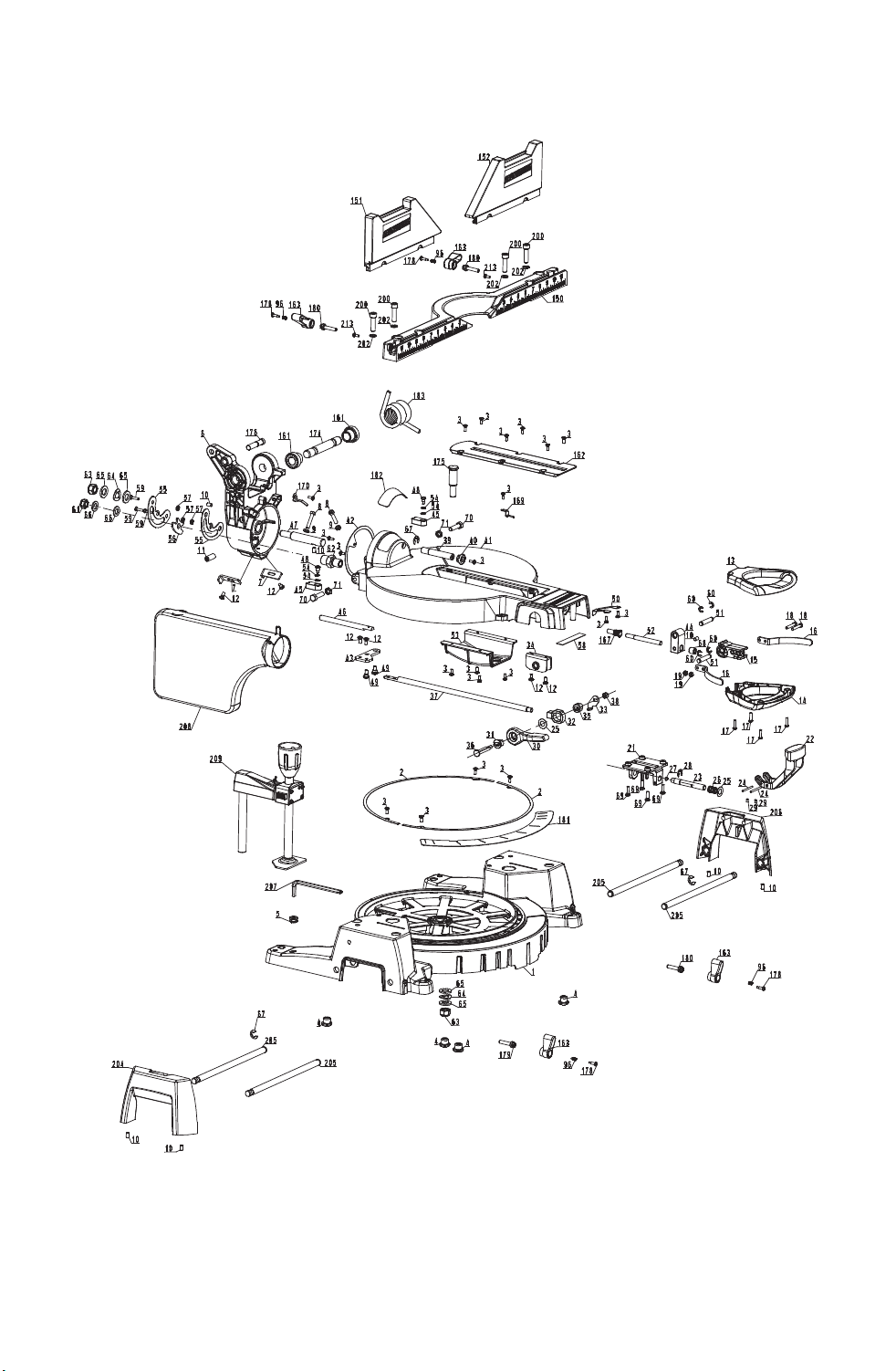
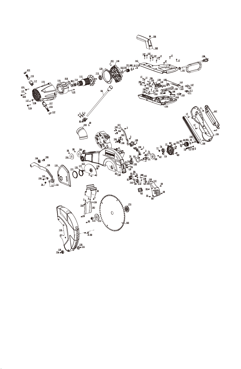
40
Exploded View
Downloaded from www.Manualslib.com
manuals search engine
41
Downloaded from www.Manualslib.com
manuals search engine

42
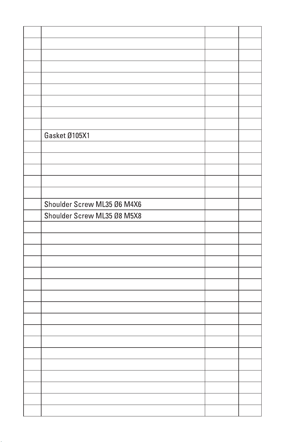
Part List
No. Part Name Quantity page
1 Base 1 A
2 Pad 2 A
3 41 A.B
4 Foot 4 A
5 Rubber Ring 1 A
6 Bevel Bracket 1 A
7 45 Bevel Override Lever 2 A
8 2 A
9 Nut M6 2 A
10 8 A.B
11 1 A
12 6 A
13 D Handle Up 1 A
14 D Handle Down 1 A
15 Miter Lock Cam 1 A
16 D Handle Support 2 A
17 13 A.B
18 2 A
19 Nut M5 2 A
20 Spring Washer 5 2 B
21 Detent Stop Support 1 A
22 Detent Stop Handle 1 A
23 Detent Stop Pole 1 A
24 Pin 4 A.B
25 2 A
26 Spring 1 A
27 Main Table Lock Slide Block 1 A
28 E Ring 1 A
29 4 A.B
30 Bevel Lock Handle 1 A
31 Bush 1 A
32 Move Holder 1 A
Downloaded from www.Manualslib.com
manuals search engine
43
33 Bevel Lock Baffle 1 A
34 Bevel Lock Bracket 1 A
35 Cam 1 A
36 Cam Shaft 1 A
37 Bevel Lock Pole 1 A
38 Nut M6 2 A.B
39 Bevel Change Pole 1 A
40 Bevel Change Knob 1 A
41 Turn Table 1 A
42 1 A
43 Bevel Lock Linker 1 A
44 Miter Lock Pad 1 A
45 33.9 Bevel Stop Pawl 2 A
46 Bevel Lock Shaft 1 A
47 Bevel Shaft 1 A
48 2 A
49 2 A
50 Spring Board 1 A
51 Pin 2 A
52 Miter Lock Pole 1 A
53 Bottom Guard 1 A
54 Wave Washer 4 A
55 Bevel Lock Pad 2 A
56 Lock Washer 1 A
57 Gasket 3 A
58 Sponge 1 A
59 Screw 3 A
60 E Ring 4 A
61 Nut M10 1 A
62 Bushing 1 A
63 Nut M12 2 A
64 Wave Washer 12 2 A
65 Washer 12 4 A
66 Washer 10 2 A
Downloaded from www.Manualslib.com
manuals search engine

44
67 E Ring 9 3 A
68 1 A
69 9 A.B
70 2 A
71 Nut M8 2 A
72 Gear Case Cover 1 B
73 Arbor Lock Pin Plate 1 B
74 Pinion 1 B
75 Arbor Lock Pin 1 B
76 Spring 1 B
77 Screw M4x8 1 B
78 Rolling Bearing 6201-2RS 1 B
79 Needle Bearing HK1010 2 B
80 Big Gear 1 B
81 Gear Shaft 1 B
82 1 B
83 Twins Laser Set 1 B
84 LED Snake Light 1 B
85 LED Mount 1 B
86 Gear Case 1 B
87 Horizontal Adjusting Support 1 B
88 Laser Cover 1 B
89 Dust Support 1 B
90 Adjusting Support 1 B
91 Bearing Cover 1 B
92 Spring Plate 2 B
93 Adjusting Spacer 1 B
94 Shaft 1 B
95 Big Pulley 1 B
96 Spring 4 A
97 Spring 1 B
98 2 B
99 Screw M4x8 8 B
100 Inner Wire Holder 1 B
Downloaded from www.Manualslib.com
manuals search engine

45
101 Inner Wire Trough 1 B
102 Dust Board 1 B
103 Washer Ø13xØ22x0.5 3 B
104 2 B
105 Rolling Bearing 1 B
106 Washer 5 2 B
107 1 B
108 Spring Washer 2 B
109 2 B
110 1 B
111 1 B
112 Rotor 1 B
113 Rolling Bearing 1 B
114 Rolling Bearing 1 B
115 Stator 1 B
116 Brush 2 B
117 Brush Holder 2 B
118 Bearing Seat 1 B
119 Motor Housing 1 B
120 Fan Baffle 1 B
121 Motor Pulley 1 B
122 Brush Cap 2 B
123 Rubber Spring 1 B
124 1 B
125 2 B
126 4 B
127 2 B
128 Roller 2 B
129 Lower Guard Plate 1 B
130 Lower Guard 1 B
131 Pad 1 B
132 Sleeve 1 B
133 Fixed Plate 1 B
134 Retaining Ring 2 B
Downloaded from www.Manualslib.com
manuals search engine

46
135 Torsion Spring 1 B
136 1 B
137 Washer 6 1 B
138 Control PCB 1 B
139 Switch PCB 1 B
140 Switch Panel 1 B
141 Switch Knob 1 B
142 Transparent Cover 1 B
143 2 B
144 Stepdown Transformer 1 B
145 Inner Wire Assy 2 B
146 1 B
147 Closed-end Wire Connecter 2 B
148 Inner Wire Assy 1 B
149 Inner Wire Assy 1 B
150 Fixed Fence 1 A
151 Left Sliding Fence 1 A
152 Right Sliding Fence 1 A
153 Up Handle 1 B
154 Down Handle 1 B
155 Carrying Handle 1 B
156 Belt Cover 1 B
157 Wire Holder 1 B
158 Switch Trigger 1 B
159 Lock Off Trigger 1 B
160 Wire Cover 1 B
161 spacer 2 A
162 Table Insert 1 A
163 Lock Knob 4 A
164 2 B
165 Linking Bushing 1 B
166 Lock Up Ring 1 B
167 Spring 1 A
168 Lower Guard Link 1 B
Downloaded from www.Manualslib.com
manuals search engine

47
169 Miter Pointer 1 A
170 Bevel Pointer 1 A
171 Inner Flange 1 B
172 Outter Flange 1 B
173 Flange Screw 1 B
174 Pivot Shaft 1 A
175 Turn table Axis 1 A
176 Lock Down Pin 1 A
177 Shoulder Screw 1 B
178 Shoulder Screw 4 A
179 Quick Lock Screw(L) 1 A
180 Quick Lock Screw(R) 3 A
181 Miter Scale 1 A
182 Bevel Scale 1 A
183 Torsion Spring 1 A
184 Tighten Screw 4 B
185 Inner Wire Fixed Cover 1 B
186 Spring 1 B
187 Spring 1 B
188 V-Belt 1 B
189 Blade-60T 1 B
190 Power Cord & Plug 1 B
191 Main Cord Guard 1 B
192 Cord Anchorage 1 B
193 Micro-Switch 1 B
194 Power Supply Indicator 1 B
195 Connecter 1 B
196 4 B
197 4 B
198 2 B
199 1 B
200 4 A
201 1 B
202 Spring Washer 4 A
Downloaded from www.Manualslib.com
manuals search engine

48
203 Dust Spout 1 B
204 Left Sliding Base 1 A
205 Extend Pole 4 A
206 Right Sliding Base 1 A
207 Wrench 1 A
208 Dust Bag Set 1 A
209 Work Piece Clamp 1 A
210 Screw 2 B
211 Terminal 2 B
212 Spring 2 B
213 2 A
WARRANTY
If, during normal use, this MASTERFORCETM power tool breaks or fails due
to a defect in material or workmanship within three years from the date of
original purchase, simply bring this tool and its sales receipt back to your
nearest Menards® retail store for a free equivalent replacement within
those three years.
The warranty:
(1) excludes expendable parts including but not limited to blades, bits, light
bulbs, and/or batteries;
(2) shall be void if this tool is used for commercial or/and rental purposes;
and
(3) does not cover any losses, injuries to persons/properties, or costs. This
warranty does give you specific legal rights and you may have other
rights, which vary from state to state.
*SAVE YOUR RECEIPTS. Your warranty is void without them. For help, please
call to our customer center, toll free number: 1-866-917-4374.
Downloaded from www.Manualslib.com
manuals search engine