
3299700
Rev.2 12/2017
CAN
US
English
Français
USE AND INSTALLATION MANUAL
MANUEL D’UTILISATION ET D’INSTALLATION
3
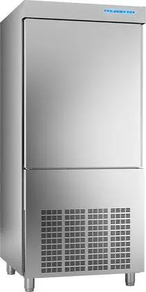
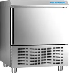
BLAST CHILLERS/FREEZERS
CELLULES DE REFROIDISSEMENT RAPIDE/CELLULES MIXTES
B151HU
B151MU
B152MU
B1101SU

Carefully read the instructions contained in the handbook. You may find important safety instructions and recommendations for use and maintenance.
Please retain the handbook for future reference.
The Manufacturer is not liable for any changes to this handbook, which may be altered without prior notice.
Lire avec attention les instructions contenues dans ce livret car elles fournissent d'importants renseignements pour ce qui concerne la sécurité, l'emploi et l'entretien.
Garder avec soin ce livret pour des consultations ultérieures de différents opérateurs.
Le constructeur se réserve le droit d'apporter des modifications à ce manuel, sans préavis ni responsabilité d'aucune sorte.
US
CAN

ES
CAN
DE
US
IT
3299702_rev.2.fIDM
English
-
1
-
Use and installation manual
1 GENERAL INFORMATION ...................................................................... 2
2 TECHNICAL INFORMATION ................................................................... 4
3 SAFETY .................................................................................................... 5
4 USE AND OPERATION ........................................................................... 7
5 SERVICING .......................................................................................... 46
6 FAULT .................................................................................................... 49
7 HANDLING AND INSTALLATION ......................................................... 51
8 REPLACING PARTS ............................................................................. 54
ANNEXES....................................................................................................I ÷ VII
A
Automatic programs, 20
C
Core probe, 9
Creating a new user program, 28
Condensing system maintenance, 47
Cleaning the cabinet, 48
Cleaning the air condenser, 49
Condensate drain, 53
Control and safety systems, 53
D
Description of controls, 11
Decommissioning the appliance, 54
E
Edit parameters cycle, 18
Edit user programs, 26
G
General description of appliance, 4
General safety precautions, 5
H
How to access the menu pages, 13
How to enter alphanumerical values, 13
I
Information for the reader, 2
Identification of constructor and appliance, 3
L
List of regualation references, 2
Length, 10
Lengthy downtimes of appliance, 45
Levelling, 52
M
Machine loading, 9
Menu structure chart, 12
Maintenance of panel board, 46
Max room temperature, 52
O
Optional accessories, 5
P
Purpose of the manual, 2
Procedure for requesting service, 4
Position of trays, 9
Programme descriptions, 14
Positioning, 52
Printer installation, 54
R
Recommendations for use, 7
Recommendations for servicing, 46
Replacement core probe, 48
Recommendations for servicing, 48
Recommendations for handling and installation, 51
Recommendations for replacing parts, 54
S
Safety devices, 5
Safety warnings for electrical equipment, 6
Safety warnings for environmental impact, 7
Setting up, 8
Switching the appliance on and off, 11
Standard programmes, 16
Special functions, 30
Settings, 39
Service, 40
Stainless-steel maintenance, 46
Sterilization lamp installation, 54
T
Technical data, 4
Temperatures, 10
Troubleshooting, 49
Table of alarm indications, 50
Transport, 51
Testing, 53
U
User programs, 25
Unpacking, 51
W
Wiring, 52
CONTENTS
INDEX
1
st
part
2
st
part

ES
CAN
DE
US
IT
3299702_rev.2.fIDM
English
-
2
-
Use and installation manual
To find the specific topics of interest to you quickly, refer to the index at the start of the
manual.
This manual is subdivided into two parts.
1
st
part: contains all information necessary for general readers, i.e. for users of
the appliance.
2
nd
part: contains all the information necessary for special categories of read-
er, i.e. all skilled operators authorised to handle, transport, install, service, re-
pair and scrap the appliance.
While users are instructed to refer to the 1
st
part only, the 2
nd
part is addressed to
skilled operators. They may also read the 1
st
part for a more complete picture of the
information provided if necessary.
–The constructor has produced this manual, which forms an integral part of the appli-
ance, to provide the necessary information for those authorised to interact with it dur-
ing its working life.
As well as adopting good practices for use, the manual's intended readers must read
it thoroughly and apply its instructions to the letter.
–The constructor supplies this information in its own language (Italian), but it may be
translated into other languages to meet legal and/or commercial requirements.
A little time taken to read this information will allow the prevention of risks to health and
safety, and the risk of economic losses.
–Keep this manual in a clearly identified safe place throughout the working life of the
appliance, so that it will always be available when required for consultation.
–The constructor reserves the right to make changes without any obligation to provide
any prior notice.
–A number of symbols have been used to highlight particularly important parts of the
text or important specifications. Their meaning is as defined below.
Caution - warning
Indicates that suitable procedures must be adopted to avoid putting people's
health and safety at risk or causing economic losses.
Important
Indicates particularly important technical information which must not be over-
looked.
The cooling cabinet we manufacture fully complies with the following European and
national regulations:
-UL Listed for electrical safety - UL471 CSA C22.2.120
-NSF standard 7 forn sanitation
GENERAL INFORMATION
1
INFORMATION FOR THE READER
PURPOSE OF THE MANUAL
LIST OF REGUALATION REFERENCES
ES
CAN
DE
US
IT
3299702_rev.2.fIDM
English
-
3
-
Use and installation manual
Make sure the technical wiring specifications comply with rating (i.e., V, kW, Hz, no.
phases and mains power).
Please quote the product’s serial number (shown on the rating plate) on any enquiry
to the Manufacturer.
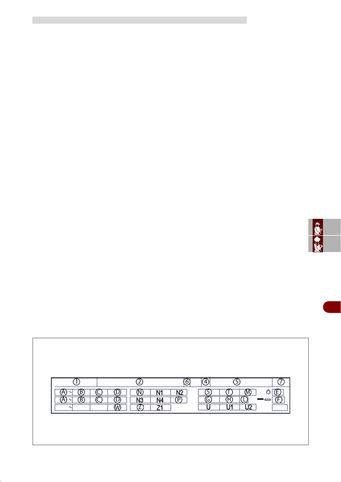
The nameplate shown here is fitted directly to the appliance. It contains references
and all essential information for operating safety.
1–Model
2–Manufacturer’s name and address
4–Year of production
5–Serial number
6–Insulation class
7–Electrical device casing protection rating
A–Input voltage
B–Electric current intensity
C–Frequency
D–Number of phase
E–Total lamp power
F–Fuse current
G–Refrigerant name
H–Mass of refrigerant
L–Climatic class
M–Max hydraulic supply pressure
N–Compressor
N1–RLA compressor
N2–LRA compressor
N3–Condenser fan
N4–FLA condenser fan
P–Expanding fluid
S–Defrost heater
T–Power defrost heater
U–Design pressure
U1–High pressure side
U2–Low pressure side
W–MCA value
Z–Evaporator fan
Z1–FLA evaporator fan
IDENTIFICATION OF CONSTRUCTOR AND APPLIANCE
ES
CAN
DE
US
IT
3299702_rev.2.fIDM
English
-
4
-
Use and installation manual
Contact one of the authorised service centres for all requirements.
When requesting service, state the data provide on the nameplate and provide a de-
scription of the fault.
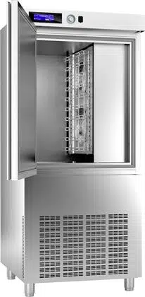
This unit is capable of reducing the temperature internal the contents from 135°F
(57°C) to 40°F (4°C) with in 4 hours, in order to conserve it for a long period of time
without altering the organoleptic characteristics.
Machine capacity as to the quantity to be cooled depend on the model purchased.
PROCEDURE FOR REQUESTING SERVICE
TECHNICAL INFORMATION
2
GENERAL DESCRIPTION OF APPLIANCE
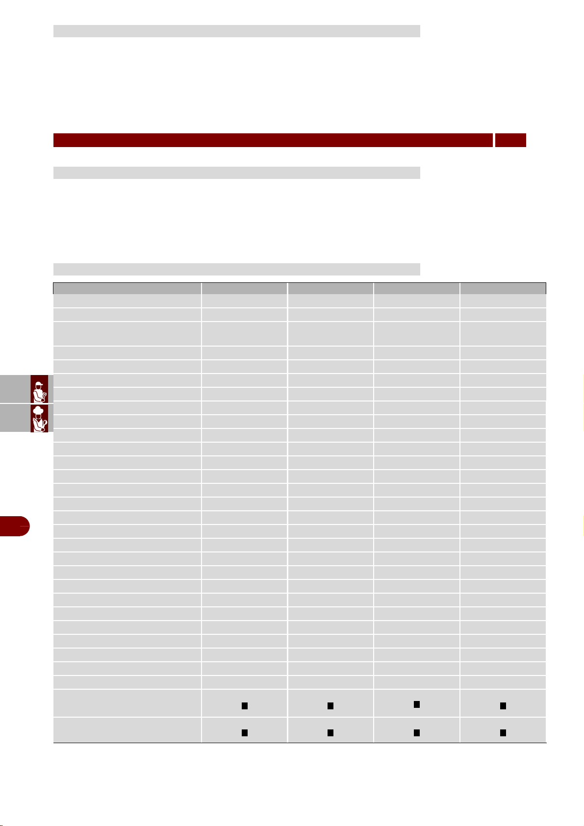
TECHNICAL DATA
B151HU B151MU B152MU B1101SU
Gross weight (lb)
309 309 342 507
Net weight (lb)
276 276 320 452
Dimensions
36.57"x30.67"x
33.07"
29.38"x28.38"x
38.19"
34.29"x35.51"x
37.28"
31.49"x32.68"x
73.23"
Capacity
Mass /cycle [lb] (+194°F ÷ +37°F)
35 48 55 100
Mass /cycle [lb] (+194°F ÷ 0°F)
22 28 33 60
Net internal volume [cuft]
2.55 2.55 3.5 5.52
Grids
3 3 3 3
Power supply
Voltage [V]
220 ~ 220 ~ 220 ~ 220 ~
Frequency [Hz]
60 60 60 60
Phase
1 ph 1 ph 1 ph 3 ph
Intensity [A]
6 6 6,13 8.5
Power input [W]
1122 1139 1520 2625
Refrigerating unit
Refrigerating power [W]
1054 1054 1319 2604
Evaporation temperature [°F]
-22 -22 -22 -22
Cooling temperature [°F]
+194 ÷ +37 +194 ÷ +37 +194 ÷ +37 +194 ÷ +37
Cooling time [min]
90 90 90 90
Freezing temperature [°F]
+194 ÷ 0 +194 ÷ 0 +194 ÷ 0 +194 ÷ 0
Freezing time [min]
240 240 240 240
Condensation temperature [°F]
+130 +130 +130 +130
Max room temperature [°F]
+90 +90 +90 +90
Compressor type
Ermetic Ermetic Ermetic Ermetic
Refrigerant name
R404A R404A R404A R404a
Mass of refrigerant [lb]
3 3 3.3 4.4
Condesation air
Air Air Air Air
Noise [dB] (A)
65 65 65 72
IFR
Multi-detector probe

ES
CAN
DE
US
IT
3299702_rev.2.fIDM
English
-
5
-
Use and installation manual
Although the appliance is complete with all safety devices, during installation and
connection additional devices must be added if necessary to comply with the relevant
legal requirements.
Caution - warning
Make a daily check that the safety devices are properly installed and in good
working order.
The appliance can be equipped with the following accessories on request (see
“general catalogue").
–During design and construction, the constructor has paid special attention to factors
which may cause risks to the health and safety of the people interacting with the ap-
pliance. As well as complying with the relative legal requirements, he has adopted all
the "rules of good construction practice”. This information is provided to encourage us-
ers to take special care in order to prevent all risks. However, there is no replacement
for care and attention. Safety also depends on all the operators who interact with the
appliance.
–Read the instructions provided in the manual supplied and those applied directly to
the appliance with care, and comply with safe instructions in particular.
–Take care not to knock or drop the appliance during transport, handling and installa-
tion, to avoid damage to its components.
–Never tamper with, elude, eliminate or bypass the safety devices installed. Failure to
comply with this rule may cause serious risks to health and safety.
–Even after you have read all the appropriate documentation, if necessary on first use
carry out a few trial operations to get to know the controls, especially those used for
switching on and off, and their main functions.
–Use the appliance only for the functions intended by the manufacturer. Improper use
of the appliance may involve health and safety risks and economic losses.
–All servicing operations requiring specific technical knowledge or skills must only be
carried out by qualified staff with recognised experience in the specific sector.
–Clean all parts which may come into direct or indirect contact with foods, and all the
surrounding areas, with care in order to maintain hygiene and protect foods from all
forms of contamination.
–When cleaning, use only food-approved detergents. Never use corrosive or flamma-
ble cleaning products, or products which contain any substances harmful for human
health.
–Carry out cleaning procedures when reasonably necessary, and always after each
use of the appliance.
SAFETY DEVICES
OPTIONAL ACCESSORIES
SAFETY
3
GENERAL SAFETY PRECAUTIONS

ES
CAN
DE
US
IT
3299702_rev.2.fIDM
English
-
6
-
Use and installation manual
–When cleaning and sanitising the appliance with detergents, always wear personal
protection equipment (gloves, masks, goggles, etc.) as required by the relevant health
and safety legislation..
–In the event of lengthy periods out of use, thoroughly clean all internal and external
parts of the appliance and the surrounding area (in accordance with the manufactur-
er’s instructions) and disconnect all supply lines.
–During routine use of the appliance, the Operator's constant presence is required.
–Never direct pressurised water jets at external or internal parts of the appliance to
avoid damage to components, especially electrical and electronic parts.
–Do not leave flammable objects or materials close to the appliance.
Important
Installations and/or repairs carried out by unauthorised staff or with non-origi-
nal parts, as with any technical change that is not approved by the manufactur-
er, will void the warranty and relieve the manufacturer of any liability for damage
to the product.
–The electrical equipment has been designed and constructed in accordance with the
relevant regulations. These regulations consider operating conditions in relation to the
surrounding environment.
–The list specifies the conditions required for the correct operation of the electrical
equipment.
-The room temperature must not be less than 41°F.
-Relative humidity must be between 50% (measured at 104°F) and 90% (meas-
ured at 68°F).
-The place of installation must be immune to electromagnetic interference and ra-
diation (X-ray, lasers, etc.) and must not be a source of these.
-The room must not have areas with concentrations of gas or powders which are
potentially explosive and/or represent a fire hazard.
-The products and materials used during production and maintenance must not
contain contaminants or corrosives (acids, chemicals, salts, etc.) and must not be
able to penetrate and/or come into contact with the electrical components.
-During transport and storage, the ambient temperature must be between -13°F
and 131°F. However, the electrical equipment may be exposed to a temperature of
up to 158°F, provided the exposure time does not exceed 24 hours.
If it is not possible to comply with one or more of the conditions listed, essential for
correct operation of the electrical equipment, agreement must be reached in the con-
tract concerning the additional features required to create the most suitable conditions
(e.g. special electrical components, air-conditioning equipment, etc.).
SAFETY WARNINGS FOR ELECTRICAL EQUIPMENT

ES
CAN
DE
US
IT
3299702_rev.2.fIDM
English
-
7
-
Use and installation manual
3
–Every organisation is obliged to apply procedures to identify and monitor the effects
of its operations (products, services, etc.) on the environment.
–The procedures for identifying significant environmental impacts must consider the
factors listed below.
-Atmospheric emissions
-Discharge of liquid effluents
-Waste management
-Soil contamination
-Use of raw materials and natural resources
-Local problems relating to environmental impact
For this purpose, the manufacture supplies information which must be considered by
all those authorised to interact with the appliance during its expected lifetime, in order
to prevent environmental impact.
–All packaging materials must be disposed of in accordance with the relevant laws in
the country of use.
–During use and maintenance, do not dump pollutants (oils, fats, etc.) in the environ-
ment; implement separate disposal as appropriate to the composition of the various
materials and in compliance with the relevant laws.
–If the appliance is scrapped, sort all components by characteristics and dispose of
them separately.
Important
Do not dump pollutant material in the environment. Dispose of it in compliance
with the relevant laws.
Important
The improper disposal of Waste Electrical and Electronic Equipment is liable to
punishment under the relevant laws in the countries where the offence is com-
mitted.
Waste electrical and Electronic Equipment may contain hazardous substances
with potential harmful effects on the environment and human health. You are
urged to dispose of them properly.
This unit is capable of reducing the internal temperature of the contents from
135°F(57°C) to 40°F (4°C) with in 4 hours, in order to conserve it for along period of
time without altering the organoleptic characteristics. Blast chiller capacity and mass
of product to be cooled depends on the model purchased.
Important
–The rate of accidents deriving from the use of appliances depends on many
factors which cannot always be predicted and controlled. Some accidents may
be caused by unpredictable environmental factors, while others are caused
above all by users’ behaviour.
SAFETY WARNINGS FOR ENVIRONMENTAL IMPACT
USE AND OPERATION
4
RECOMMENDATIONS FOR USE

ES
CAN
DE
US
IT
3299702_rev.2.fIDM
English
-
8
-
Use and installation manual
These, as well as being authorised and suitably trained, if necessary, shall
simulate some manoeuvres to identify the controls and main functions, for
operation training purposes.
–Use only as intended by the manufacturer and do not tamper with any devices
to obtain operations other than those intended.
–Before each use, make sure that the safety devices are fully installed and efficient.
–Before use, check that the safety devices are properly installed and in good
working order.
–As well as undertaking to comply with these requirements, users must apply
all safety regulations and read the description of the controls and the start-up
instructions carefully.
–Immediately report any anomaly or deterioration of the components and/or
parts of the unit and if necessary ask qualified staff to intervene for the
inspection and/or replacement activities.
Before setting to operation thoroughly clean the cooling cabinet with a suitable
detergent or sodium bycarb dissolved in lukewarm water. Clean the appliance inside
to remove any condensate caused by the Manufacturer's final testing.
Cooling and freezing speed depends on the following factors:
a) container shape, type and material;
b) whether container lids are used;
c) foodstuff features (density, water contents, fat contents);
d) starting temperature;
e) thermal conduction inside the foodstuffs.
Positive /Negative quick cooling time depends on type of foodstuffs to be processed.
In general the programmes the machine is equipped with are based on the chamber
temperature management, the fan speed and the chilling time, in any case never
exceed 7lb of load (for 12”x20” pans) or 15lb of load (for 18”x26” pans) and a thickness
of 2” in negative chilling phase and 3” in positive chilling phase.
Check that the positive chilling programme, up to +37°F at the product core, does not
take more than 90 minutes and that the negative chilling programme, up to 0°F at the
product core, does not take more than 4 hours.
We recommend pre-chilling the work chamber before beginning with a chilling
programme and not covering the food during the programme in order not to increase
times.
We recommend using the core probe in order to have the exact core temperature
reading. Do not stop the cycle before reaching a temperature of +37°F during positive
quick cooling and 0°F during negative quick cooling.
SETTING UP
Model Max. output/cycle Standard
of shelves
Capacity h
+194°F ÷ +37°F +194°F ÷ -0°F n°max
B151HU 35 lb 22 lb 3 10
12”x20”
1.5”
B151MU 48 lb 28 lb 3 6
12”x20”
1.5”
B152MU 55 lb 33 lb - 6
18”x26”
1.5”
B1101SU 100 lb 60 lb 3 12
12”x20”
1.5”
ES
CAN
DE
US
IT
3299702_rev.2.fIDM
English
-
9
-
Use and installation manual
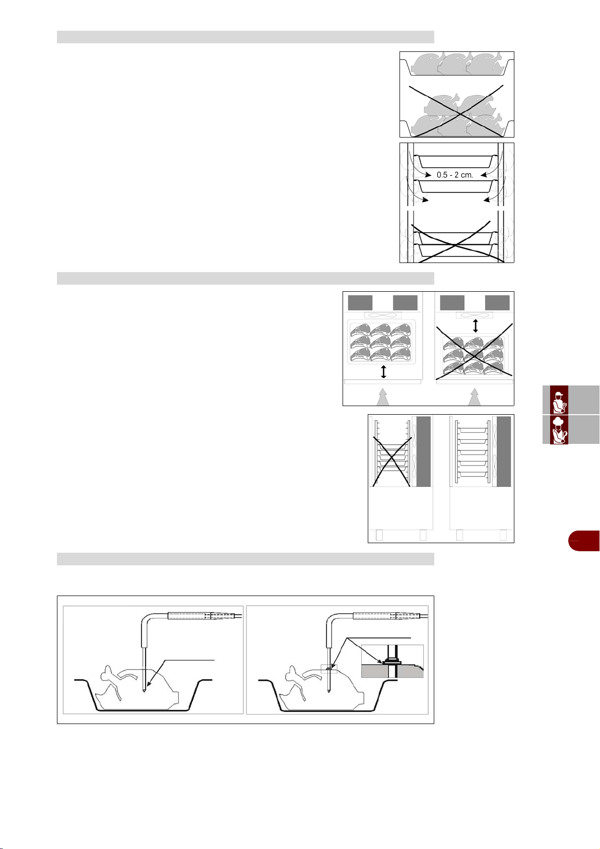
Do not pile up foodstuffs to be cooled.
Thickness should be lower than 2” in negative quick cooling and lower than
3” in positive quick cooling.
Make sure air circulation is not hampered between food trays.
Place the trays as close to the evaporator as possible.
If the cabinet is not full place the trays at equal distance from one
another.
For proper position of the probe, refer to the following pictures
MACHINE LOADING
POSITION OF TRAYS
CORE PROBE
product core
product surface
MULTI-DETECTOR
PROBE
SINGLE-DETECTOR
PROBE
ES
CAN
DE
US
IT
3299702_rev.2.fIDM
English
-
10
-
Use and installation manual
Do not leave the cooked products that are to be chilled/frozen at room temperature.
Avoid humidity losses, which will be detrimental to the conserved fragrance of the
product.
We recommend beginning the chilling/freezing program as soon as the preparation or
cooking phase has ended, being careful to insert the product into the equipment at a
temperature no lower than +160°F. The cooked product can enter the equipment even
at very high temperatures, greater than +212°F, as long as the chamber has been pre-
chilled.
In any case it should be taken into consideration that the programme reference times
always start from a temperature of +194°F, in positive chilling from +194°F to +37°F
and in negative chilling from +194°F to 0°F.
Cooled or frozen processed foodstuffs may be stored in a refrigerator for 5 days of
processing with no quality alterations.
For best results we recommend keeping temperature constant throughout the storing
(32°F to 39°F), according to the various commodities.
Storing time may be increased to approx. two weeks by using vac-
uum processing.
After a negative quick cooling cycle, foodstuffs may be stored safely
for 3 to 18 months, according to the type of foodstuff processed.
We strongly recommend keeping storing temperature at -4°F or be-
low.
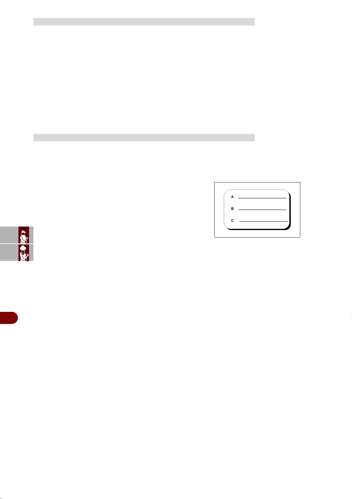
The cooled product should be wrapped in a specific film for food-
stuffs (better still, vacuum stored) and provided with a sticker report-
ing the content [A], date of processing [B] and expiry date [C] written
in permanent type ink.
TEMPERATURES
LENGTH
ES
CAN
DE
US
IT
3299702_rev.2.fIDM
English
-
11
-
Use and installation manual
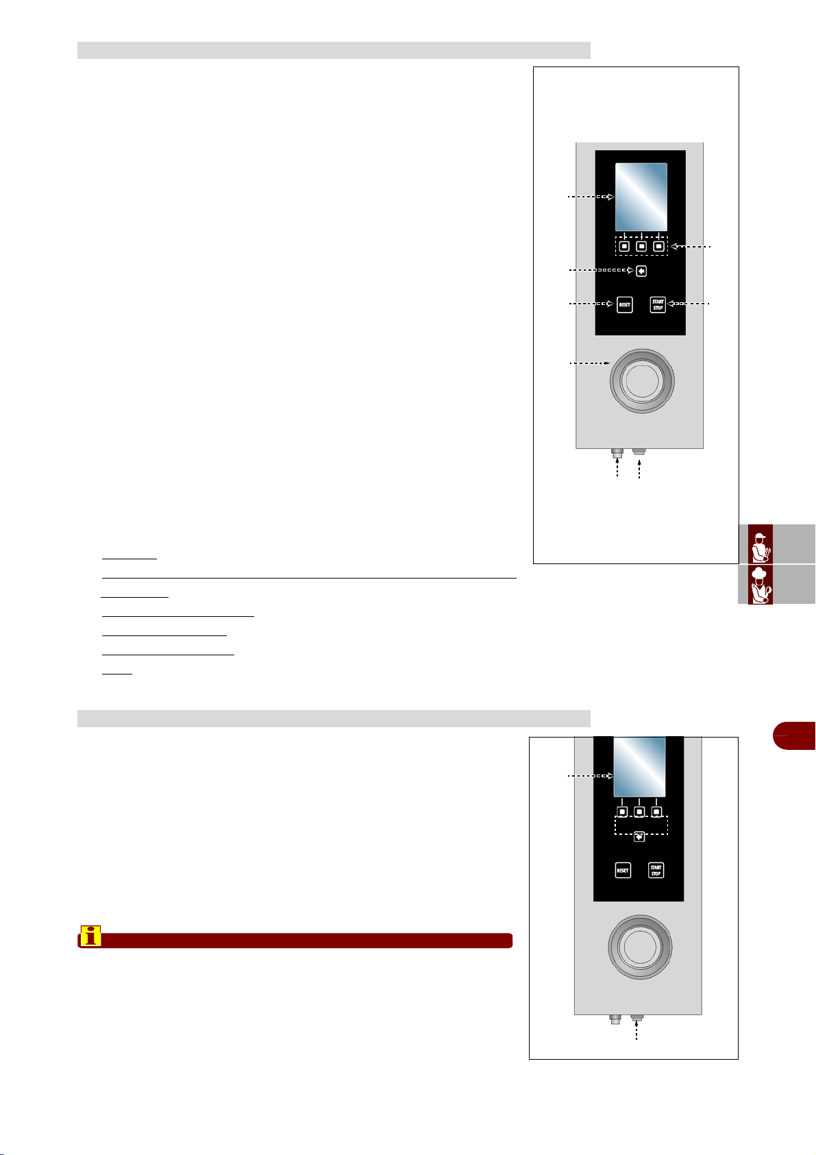
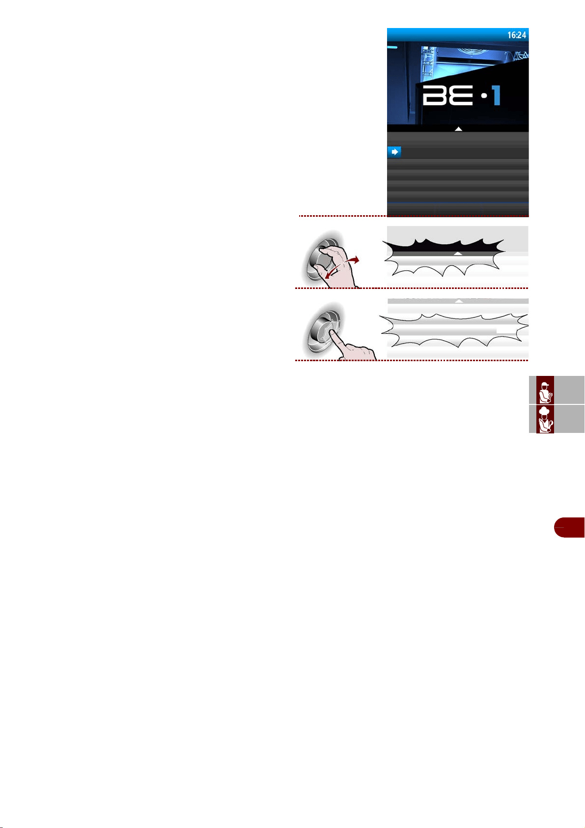
The illustration shows the appliance’s control panels, while the list details
the descriptions and functions of the individual controls.
A–Digital display: displays the working parameters and alarm codes.
B–Function enabling button. enables the function shown on the dis-
play.
C–Back button: cancels the current operation and returns to the previ-
ous page.
D–Reset button: resets the alarms (beepers and lights).
E–"START-STOP" button: Starts or ends the selected program cycle,
shown on the display.
F–Knob: Used to select the function required or modify values.
To select one of the zones required (function or value) turn the knob clock-
wise or anticlockwise.
-Clockwise: scrolls "downwards" through zones or increases the value
shown.
-Anticlockwise: scrolls "upwards" through zones or decreases the val-
ue shown.
After selecting the function required or the value, press the knob to con-
firm and save the function or value.
G–On/off button: turns the appliance's electricity supply on and off.
H–
USB port
: used to connect a remote data storage unit to the appliance.
L–"Blast chiller" emergency key: it is used in the event of an oven
board anomaly to activate a Soft +37°F blast chilling cycle.
M–The RGB LED bar, built into the door handle or on the dashboard,
takes on a different colour depending on the process in progress:
-Stand-by
: low intensity steady light blue light
-Chilling/freezing cycle (including infinity, Multy) Defrost and Cooling,
in progress: high intensity flashing light blue light
-Conservation in progress
: high intensity steady light blue light
-Freezing in progress
: high intensity steady red light
-Sanitation in progress
: low intensity steady red light
-Fault
: steady yellow light
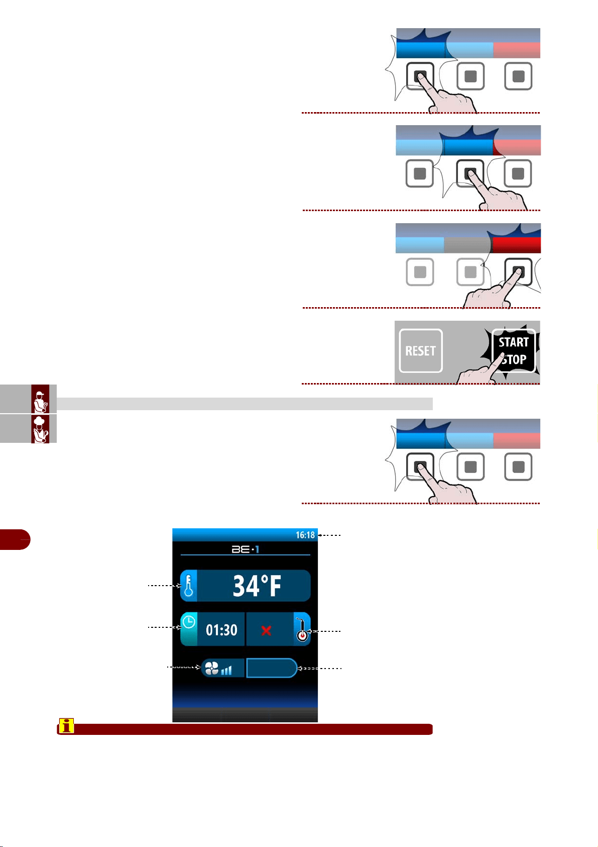
Proceed as follows.
Lighting
1–Operate the appliance's master switch to connect it to the electrical
mains.
2–Turn on the water supply tap.
3–Press button (G) to switch on the appliance.
4–The display (A) comes on, and after a few seconds it shows the page
giving access to the appliance’s main functions.
Turning off
Important
Always switch off the appliance after use.
5–Press button (G) to switch off the appliance.
6–Turn off the water supply tap.
7–Cut off the mains electricity supply using the appliance's master
switch.
DESCRIPTION OF CONTROLS
SWITCHING THE APPLIANCE ON AND OFF
IDM-39617700300.tif
A
C
D
F
B
E
G
H
A
G
ES
CAN
DE
US
IT
3299702_rev.2.fIDM
English
-
12
-
Use and installation manual
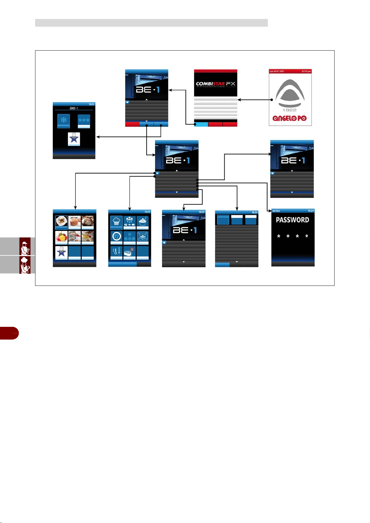
The chart shows the structure sequence of the main pages covering the various oper-
ating modes.
A–Presentation page: displayed when the appliance is switched on.
B–Main functions page (home page oven): used to access the pages for program-
ming and display of the appliance’s operating parameters (see page 12)
C–Main functions page (home page blast chiller): used to access the pages for
programming and display of the appliance’s operating parameters (see page 12) anf
for to select predefined blast chilling cycles. (see page 16).
D–“"Menu" page: to access the blast chiller menu.
E–Automatic programs" page: Chilling/freezing cycles recommended by the man-
ufacturer (see page 20).
F–"Special functions" page: proving, thawing, yogurt box, parasites, storage, de-
frost, cooling, IFR (see page 30).
G–"Settings" page: used to set the functioning parameters of the appliance (see
page 39).
H–"Service" page: function for the exclusive use of the After-Sales technical assist-
ance service (to be used with Password).
L–"HACCP" page: used to display the HACCP data acquired during different cook-
ing.
M–"Data load/download" page: (USB Memory).
N–"User programs" page: cycles that can be configured based on the needs of the
user, the names of which can be freely set (see page 25).
MENU STRUCTURE CHART
(D) “ Menù” page
(B) Main functions page
(home page blast oven)
(A) Presentation page
(N) “user programs"
page
(C) Main functions page (home
page blast chiller) / “Standard
programs"
(E) “Automatic programs"
page
(G) “Setting" page
(H) “Service" page
(F) “Special functions"
page
(M) “Data load /
download" page
(L) “HACCP" page
ES
CAN
DE
US
IT
3299702_rev.2.fIDM
English
-
13
-
Use and installation manual
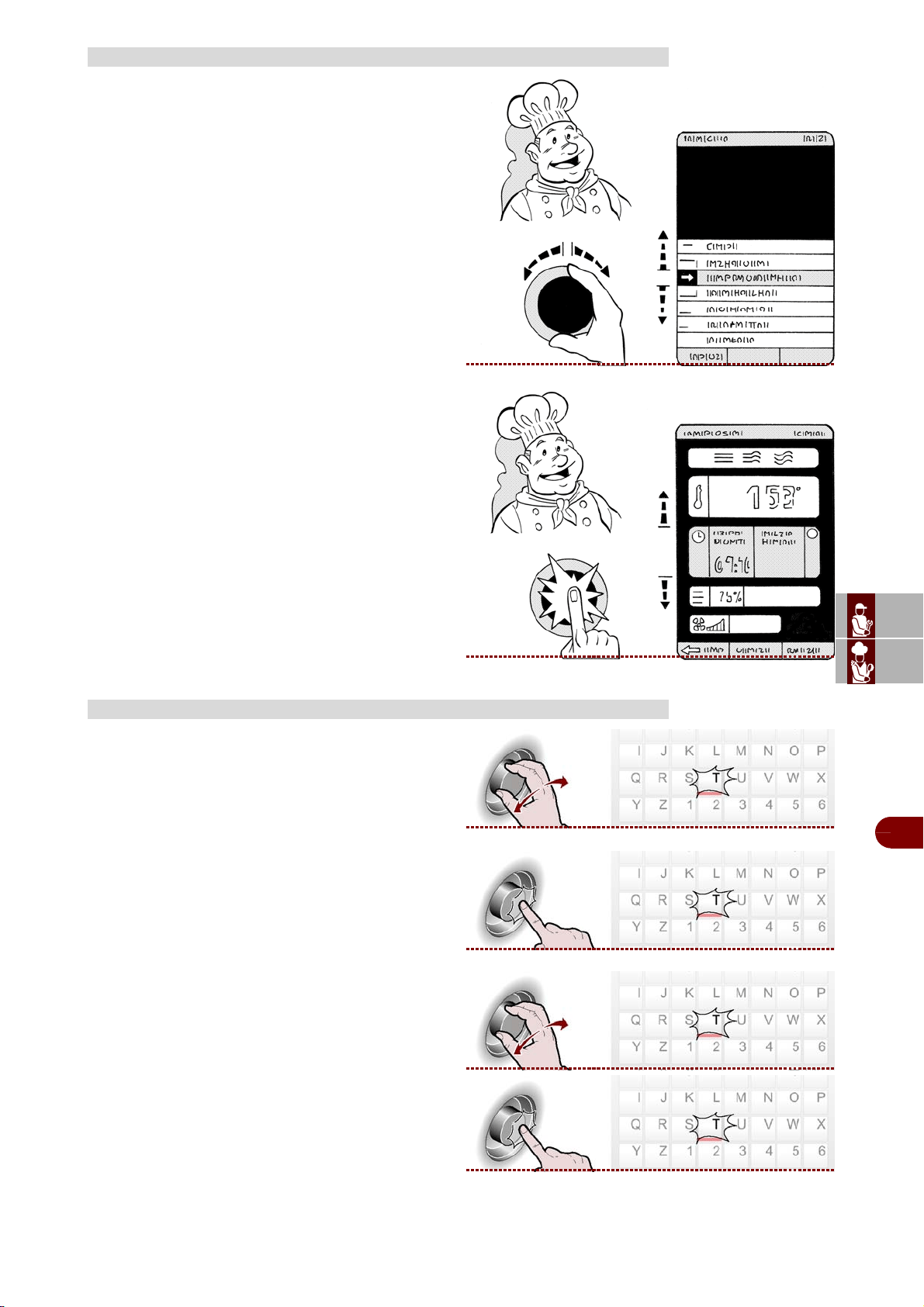
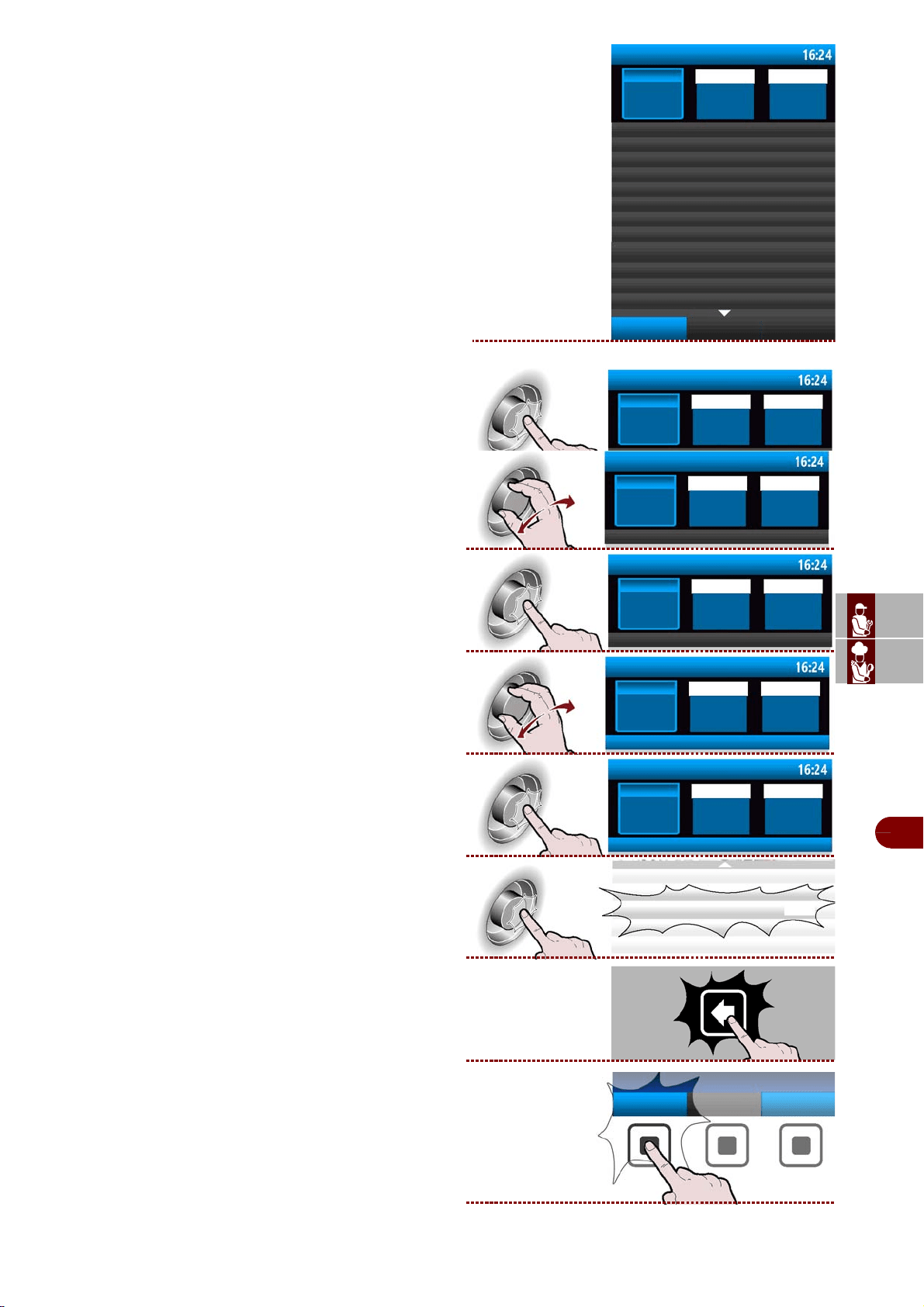
Proceed as follows.
1–Select the function required (submenu) using the
knob.
2–Press the knob to confirm the selected function.
3–Select the parameter to be modified using the
knob.
4–Press the knob to confirm the selected parame-
ter.
5–Modify the value of the selected parameter using
the knob.
6–Press the knob to confirm the new value dis-
played.
Proceed as follows.
1–Use the knob to select the first character (letter or
number) required. >>>
2–Press the knob to confirm the highlighted selec-
tion. >>>
3–Select the second character (letter or number) re-
quired using the knob. >>>
4–Press the knob to confirm the highlighted selec-
tion. >>>
5–Repeat the operation until the complete value or
parameter has been entered.
HOW TO ACCESS THE MENU PAGES
HOW TO ENTER ALPHANUMERICAL VALUES
ES
CAN
DE
US
IT
3299702_rev.2.fIDM
English
-
14
-
Use and installation manual
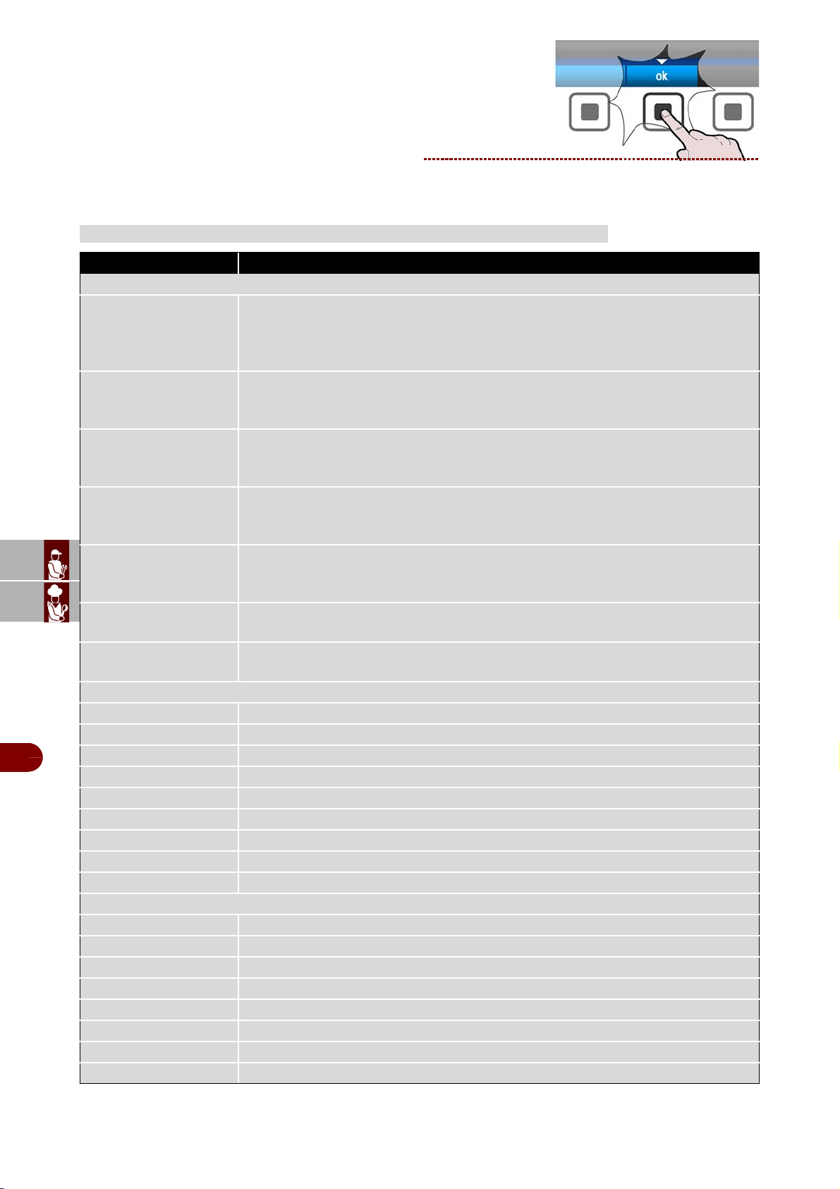
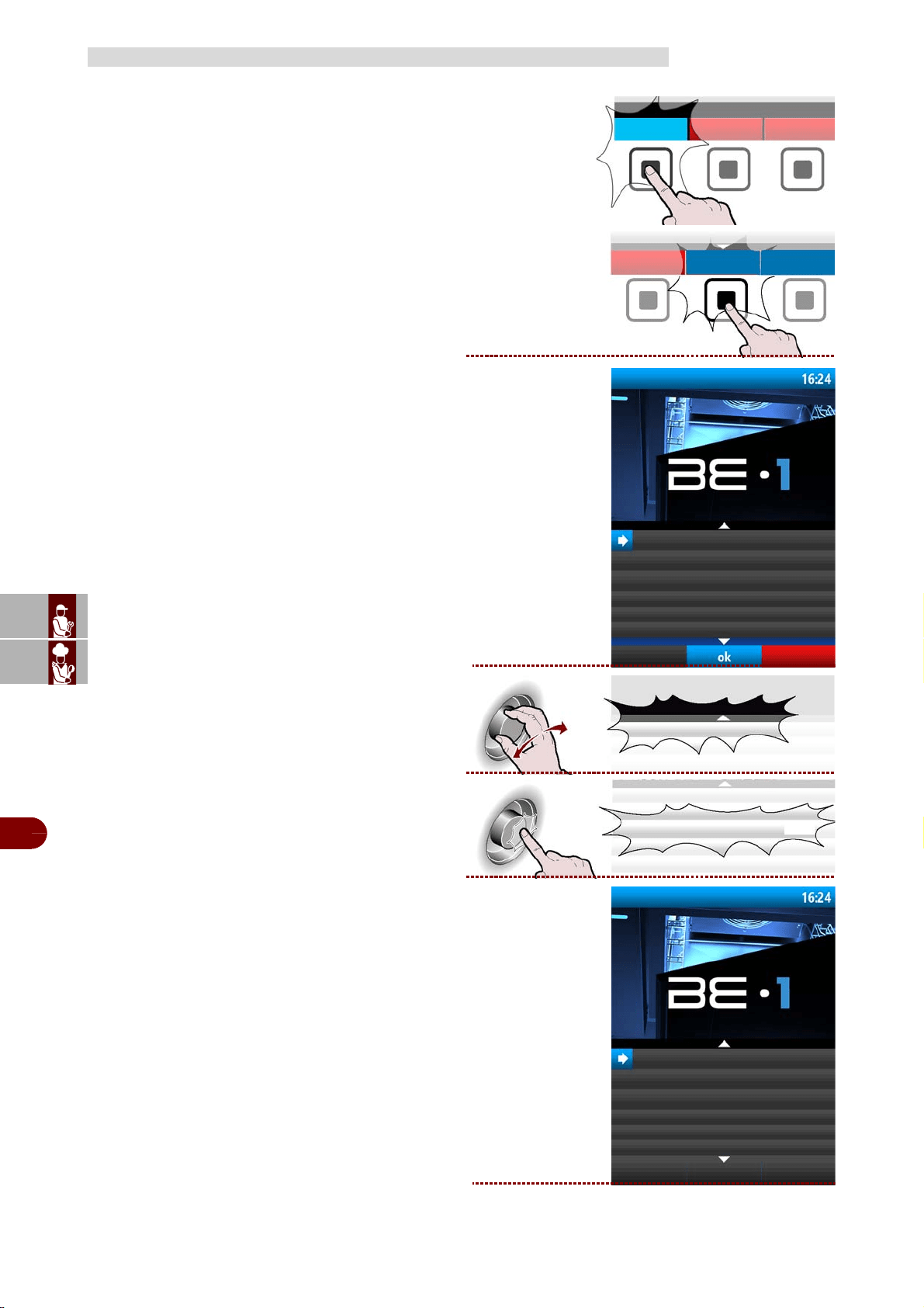
6–Press the button to confirm the value or descrip-
tion selected. >>>
PROGRAMME DESCRIPTIONS
PROGRAM DESCRIPTION
STANDARD PROGRAMS
SOFT +
Cycle carried out through probe at the core or time, suitable for chilling foods up to
+37°F, using a chamber temperature of about 0°F.
Cycle suitable for delicate products such as mousse, creams, desserts, vegetables
or foods that are not very thick
HARD +
CCycle carried out through probe at the core or time, suitable for chilling foods up to
+37°F, using a chamber temperature varying from 5°F to 34°F.
Cycle suitable for very dense products, with high grease content or large sized products
SOFT -
Cycle carried out through probe at the core or time, suitable for freezing foods up to
0°F, using a chamber temperature varying from 34°F to -40°F.
Cycle suitable for leavened products, baked or cooked foods that are not very thick
HARD -
Cycle carried out through probe at the core or time, suitable for freezing foods up to
0°F, using a chamber temperature that can reach -40°F.
Cycle suitable for raw or cooked, large size foods
IFR-ECO
I.F.R. is the patented positive blast chilling system that automatically optimises the
process for any type of food, no matter the size and quantity, chilling its surface
thanks to the use of a multipoint, three sensor needle probe
MULTY-INFINITY
Time chilling/freezing cycle with infinite duration, suitable for cooling various type
food pans. The temperature at the core can be checked
DEFROSTING
Evaporating battery cleaning cycle to remove the ice on the surface in order to op-
timise the operation of the blast chiller.
AUTOMATIC PROGRAMS +37°F - CATERING
LASAGNE Cycle dedicated to chilling of lasagne
SOUPS AND SAUCES Cycle dedicated to chilling of soups and sauces
RICE AND PASTA Cycle dedicated to chilling of rice and pasta
MEAT Cycle dedicated to chilling of meat
FISH Cycle dedicated to chilling of fish
COOKED VEGETABLES
Cycle dedicated to chilling of cooked vegetables
HOT PASTRY Cycle dedicated to chilling of hot pastry products
DRY PASTRY Cycle dedicated to chilling of dry pastry products
WALNUTS VEAL Cycle dedicated to chilling of walnuts veal
AUTOMATIC PROGRAMS 0°F - CATERING
LASAGNE Cycle dedicated to freezing of lasagne
SOUPS AND SAUCES Cycle dedicated to freezing of soups and sauces
RICE AND PASTA Cycle dedicated to freezing of rice and pasta
MEAT Cycle dedicated to freezing of meat
FISH Cycle dedicated to freezing of fish
COOKED VEGETABLES
Cycle dedicated to freezing of cooked vegetables
RAW VEGETABLES Cycle dedicated to freezing of raw vegetables
PASTRY Cycle dedicated to freezing of pastry products

ES
CAN
DE
US
IT
3299702_rev.2.fIDM
English
-
15
-
Use and installation manual
RAW FISH Cycle dedicated to freezing of raw fish
SUSHI Cycle dedicated to freezing of Sushi
ANISAKIS 24h*
It is a special blast freezing cycle that enables preventive and total food preservation
and restoration. Once the probe reads -4°F at the food core, the appliance will au-
tomatically start the "devitalization phase for 24 hours”
ANISAKIS 15h*
it is a special blast freezing cycle that enables preventive and total food preservation
and restoration. Once the probe reads -31°F at the food core, the appliance will au-
tomatically start the "devitalization phase for 15 hours”
OPISTORKIS 24h
It is a special blast freezing cycle that enables preventive and total food preservation
and restoration. Once the probe reads -4°F at the food core, the appliance will au-
tomatically start the "devitalization phase for 24 hours”
AUTOMATIC PROGRAMS +37°F - PASTRY SHOP
DOUGH SHEETING Cycle dedicated to chilling of sheet dough
MIXING IN DIE Cycle dedicated to chilling of moulded dough
CREAM Cycle dedicated to chilling of creams
DIRECT LEAVENING Cycle dedicated to chilling of leavened products
DOUBLE LEAVENING
50°F
Cycle dedicated to chilling of leavened products +50°F
SHORT PASTRY Cycle dedicated to chilling of shortcrust dough
STUFFED PRODUCTS Cycle dedicated to chilling of filled products
TARTS Cycle dedicated to chilling of tarts
BRIOCHE Cycle dedicated to chilling of brioche
PANNA COTTA Cycle dedicated to chilling of panna cotta
YOGURT BOX Cycle dedicated to preparing of yogurt
AUTOMATIC PROGRAMS 0°F - PASTRY SHOP
DOUGH SHEETING Cycle dedicated to freezing of sheet dough
MIXING IN DIE Cycle dedicated to freezing of moulded dough
TARTS Cycle dedicated to freezing of tarts
MOUSSE Cycle dedicated to freezing of mousse
CROISSANT Cycle dedicated to freezing of croissants
ICE CREAM Cycle dedicated to freezing of ice cream
AUTOMATIC PROGRAMS +37°F - BAKERY
TARTS Cycle dedicated to chilling of tarts
BAKED BREAD Cycle dedicated to chilling of baked bread
CREAM Cycle dedicated to chilling of creams
LEAVENED Cycle dedicated to chilling of leavened products
AUTOMATIC PROGRAMS 0°F - BAKERY
COOKED TARTS Cycle dedicated to freezing of baked tarts
RAW TARTS Cycle dedicated to freezing of unbaked tarts
BAKED BREAD Cycle dedicated to freezing of baked bread
UNCOOKED BREAD Cycle dedicated to freezing of unbaked bread
AUTOMATIC PROGRAMS +37°F - ICE CREAM PARLOUR
PANNA COTTA Cycle dedicated to chilling of panna cotta
YOGURT BOX Cycle dedicated to preparing of yogurt
AUTOMATIC PROGRAMS 0°F - ICE CREAM PARLOUR
ICE CREAM -7°F Cycle dedicated to freezing of ice cream -7°F
ICE CREAM Cycle dedicated to freezing of ice cream
COMPLETE MOUSSE Cycle dedicated to freezing of complete mousse
MOUSSE Cycle dedicated to freezing of mousse
FROZEN DESSERT Cycle dedicated to freezing of frozen dessert
PROGRAM DESCRIPTION
ES
CAN
DE
US
IT
3299702_rev.2.fIDM
English
-
16
-
Use and installation manual
* Tested and validated in cooperation with: University of Naples Federico II - Department of Zootechnical
Sciences and Food inspection and the University Research laboratory at the wholesale fish market of Poz-
zuoli, Naples
Important
Do not turn off the oven when the blast chiller is in operation.
Chilling/freezing cycles pre-set by the manufacturer which can be activated by select-
ing them directly from the initial screen, SOFT+, HARD+, SOFT-, HARD-, IFR-ECO,
MULTY-INFINITY, DEFROSTING.
During execution of the cycle the parameters can be viewed and modified temporarily.
The new values will be valid exclusively for the cycle in progress.
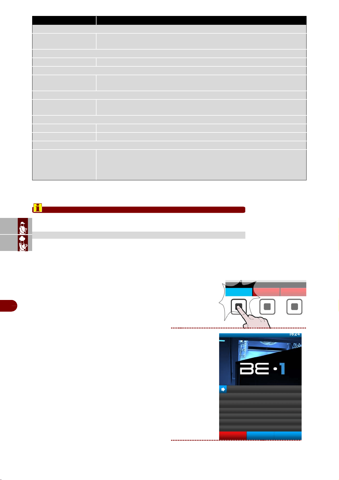
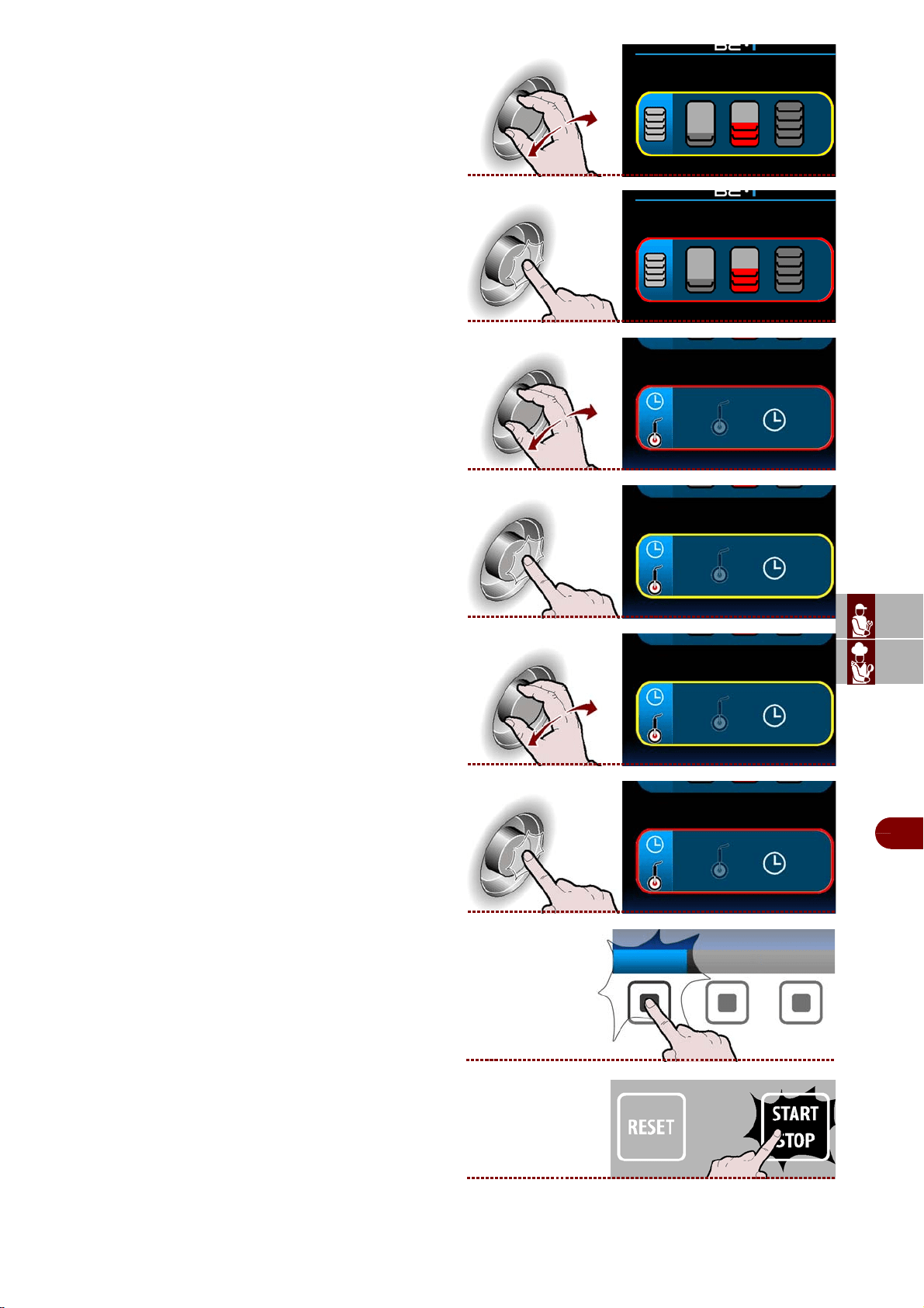
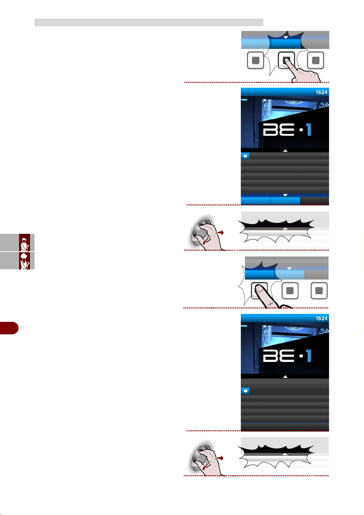
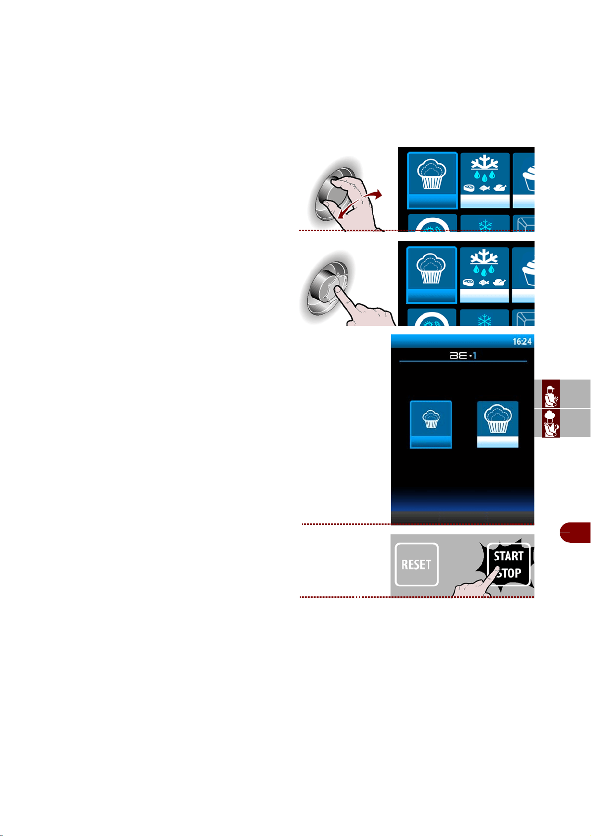
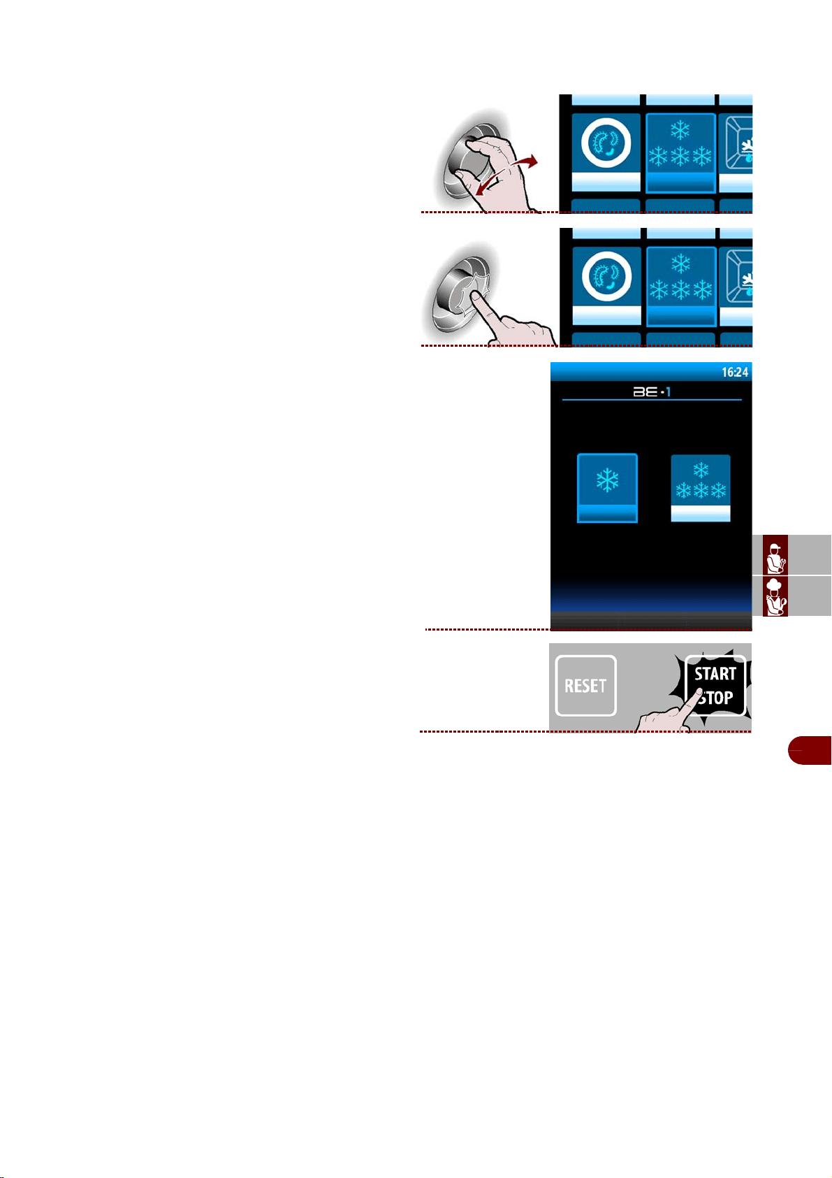
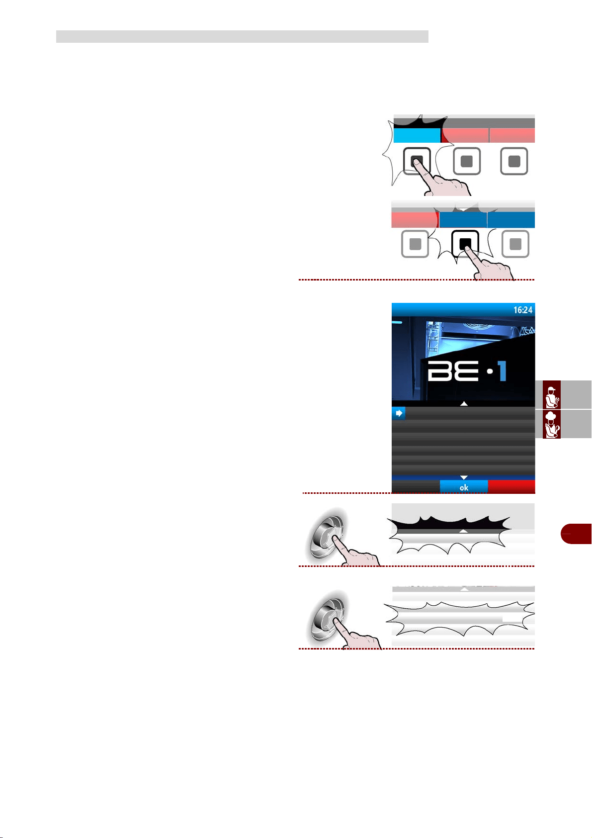
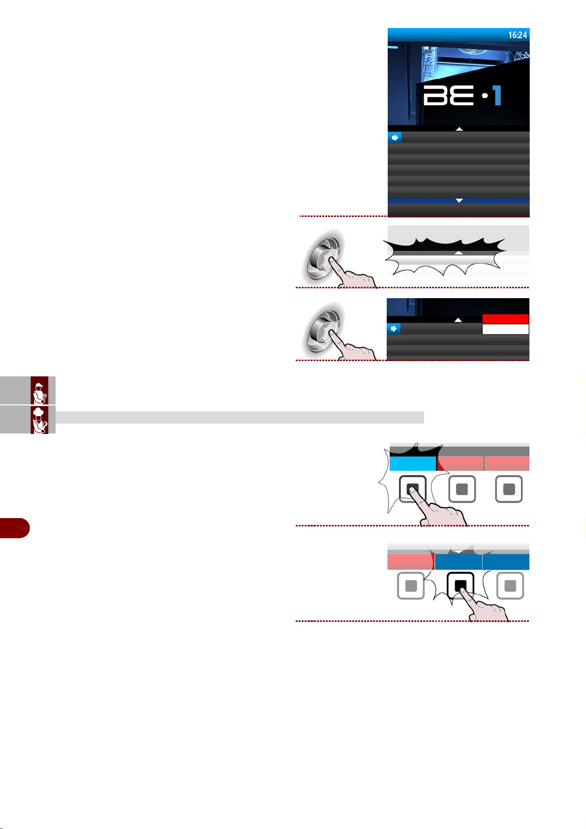
Proceed as follows.
1– From the screen main functions (home page ov-
en), press the button to enter the mode blast chiller.
2–The display will show page
( home page blast chiller) . >>>
MULTY PROGRAM
MULTY
Time chilling/freezing cycle, organised by load levels, with possibility of needle
probe reading, providing the time for each level
BANQUETING PROGRAM
BANQUETING
Cycle dedicated to the catering sector, excellent for preparation of banqueting products
VACUUM PROGRAM
VACUUM
Cycle dedicated to the catering sector for preparation of products before a vacuum-
packing phase
THAWING PROGRAMME
THAWING
Cycle carried out by means of temperature probe or by time, dedicated to controlled
food defrosting
PROVING PROGRAM
PROVING Time cycle, dedicated to direct leavening of foods
RETARDER PROVING Time cycle, dedicated to scheduled leavening of foods
PROGRAMMA SMART ON
SMART ON
Cycle with automatic start.
Once a hot product is inserted if an increase in the chamber temperature is detect-
ed, after 5 minutes a Soft +37°F cycle will start, either by probe or time, based on
whether or not the needle is used.
STANDARD PROGRAMS
PROGRAM DESCRIPTION
blast chiller
SOFT +
HARD +
SOFT -
HARD -
IFR-ECO
MULTY-INFINITY
DEFROSTING:
oven menù
user
program
ES
CAN
DE
US
IT
3299702_rev.2.fIDM
English
-
17
-
Use and installation manual
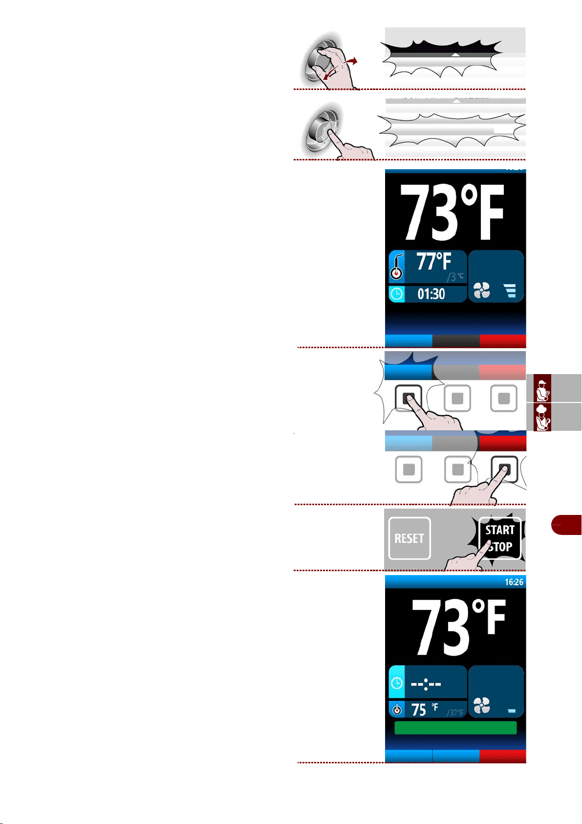
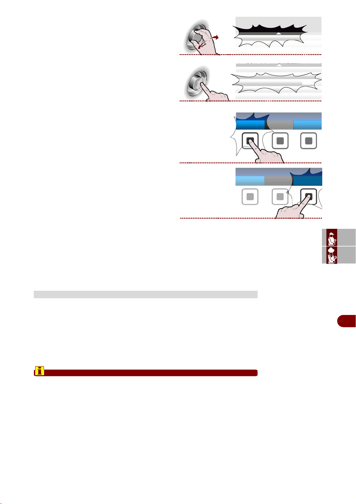
3–Select the desired cycle with the knob. >>
4–Press the knob to confirm the selected choice.
>>>
The display will show page. >>>
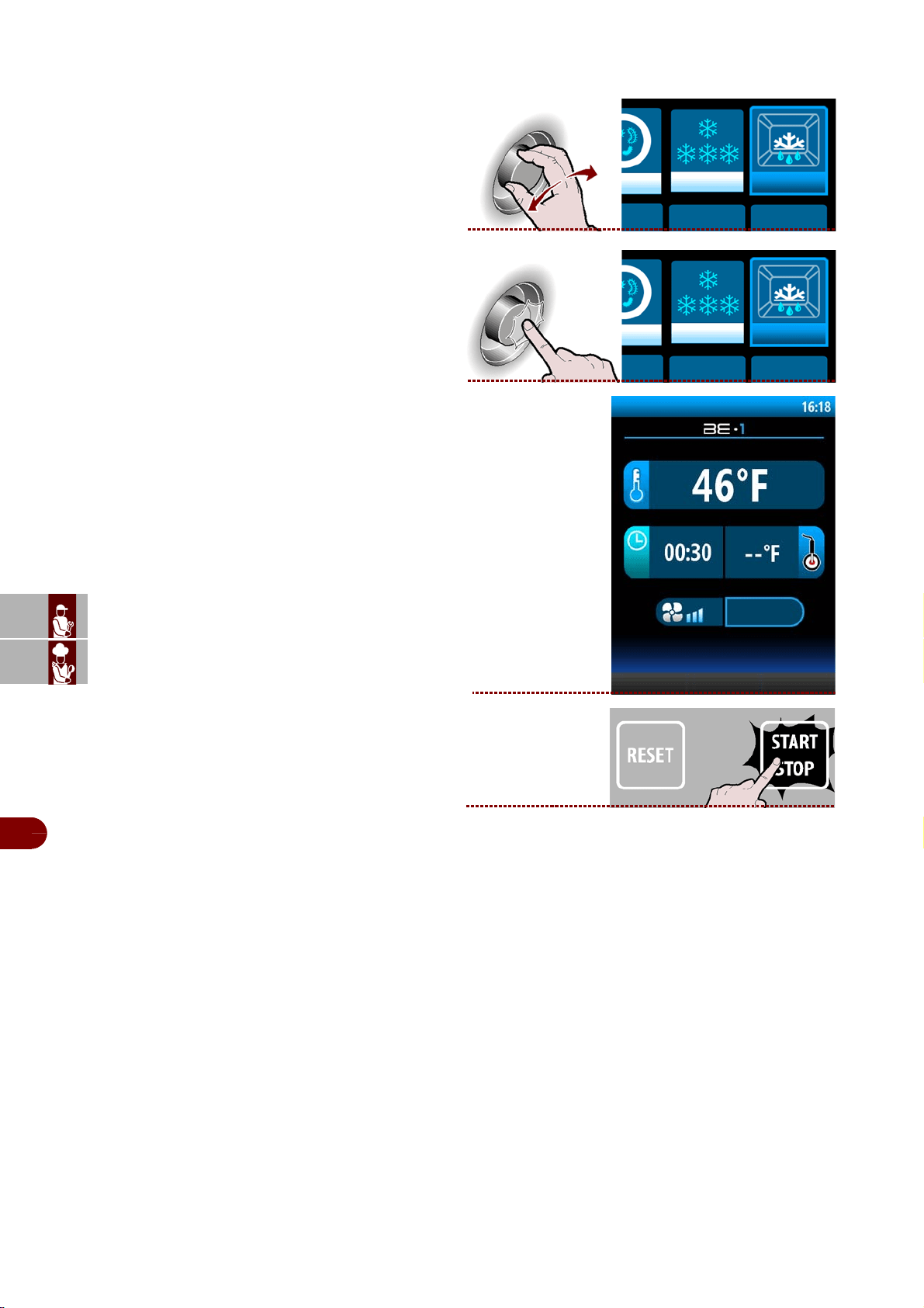
During the cycle it is possible:
-to view and modify the default parameters (see
page 18).
Note: the modified parameters will be saved
only for the cycle in progress.
-select the oven function
.
-to stop the cycle.
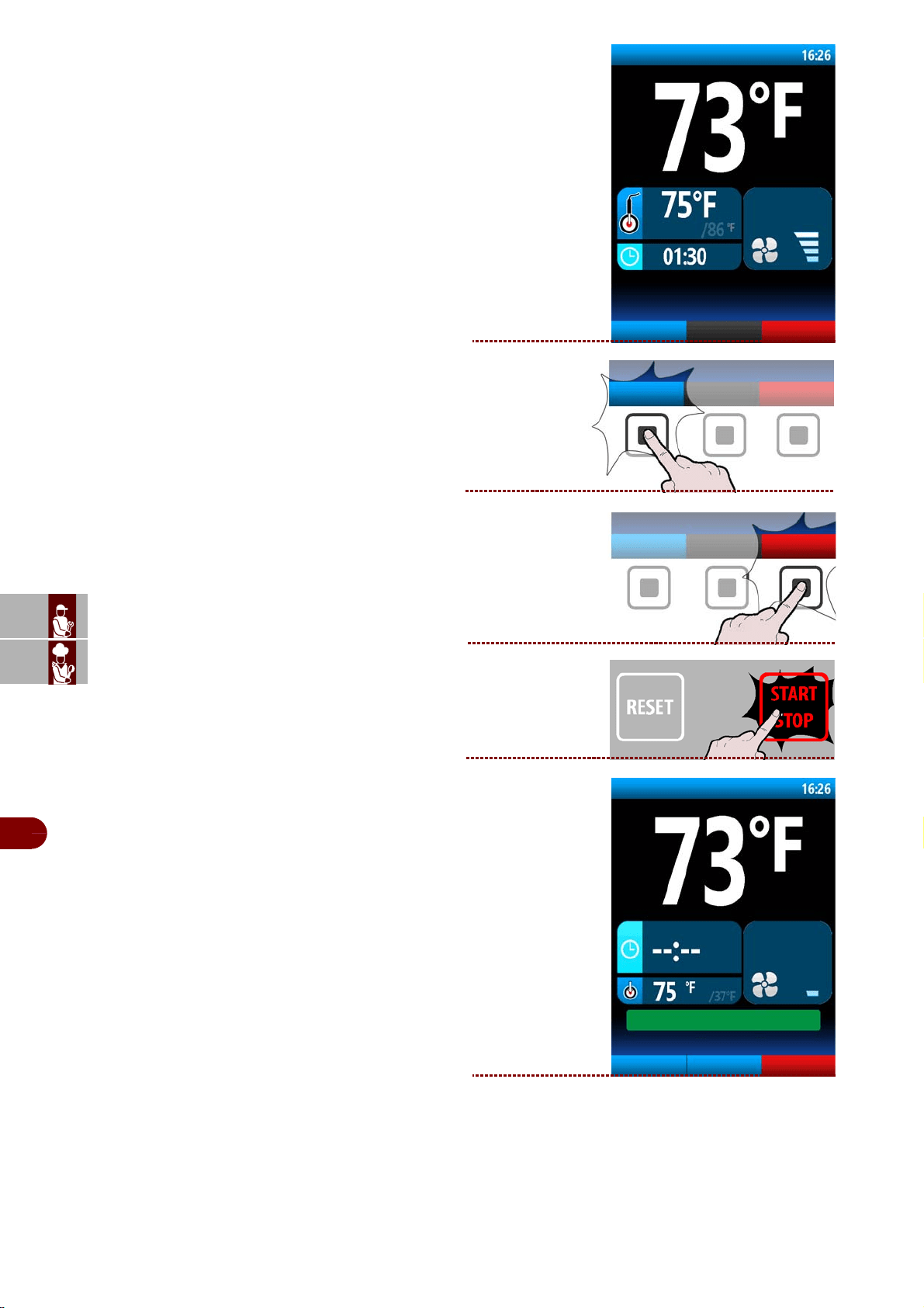
5–
Cycle ended, automatic conservation phase.
The display will show page. >>>
SOFT +37°F
SOFT +3°C
phase 1/2
oven
modify
parameters
modify
parameters
oven
phase 2/2
oven
modify
parameters
defrost
CYCLE COMPLETED: STORAGE IN PROGRESS
SOFT +
ES
CAN
DE
US
IT
3299702_rev.2.fIDM
English
-
18
-
Use and installation manual
During conservation it is possible:
-to view and modify the default parameters (see
page 18).
Note: the modified parameters will be saved
only for the cycle in progress.
-to activate a manual defrost.
If not required, manual defrosting is not per-
formed.
-select the oven function
.
-to stop the cycle.
1–During the cycle, select “modify parameters”.
>>>
2–The display will show page.
Important
The "chilling time" and "core temperature" functions are mutually exclusive.
For example, if a user selects "chilling time" and then selects "core tempera-
ture", the first function is cancelled.
EDIT PARAMETERS CYCLE
modify
parameters
defrost
oven
modify
parameters
chamber
temperature
chilling time
“Core" tem-
perature
fan speed
number of phases
program
time
fase 1/2

ES
CAN
DE
US
IT
3299702_rev.2.fIDM
English
-
19
-
Use and installation manual
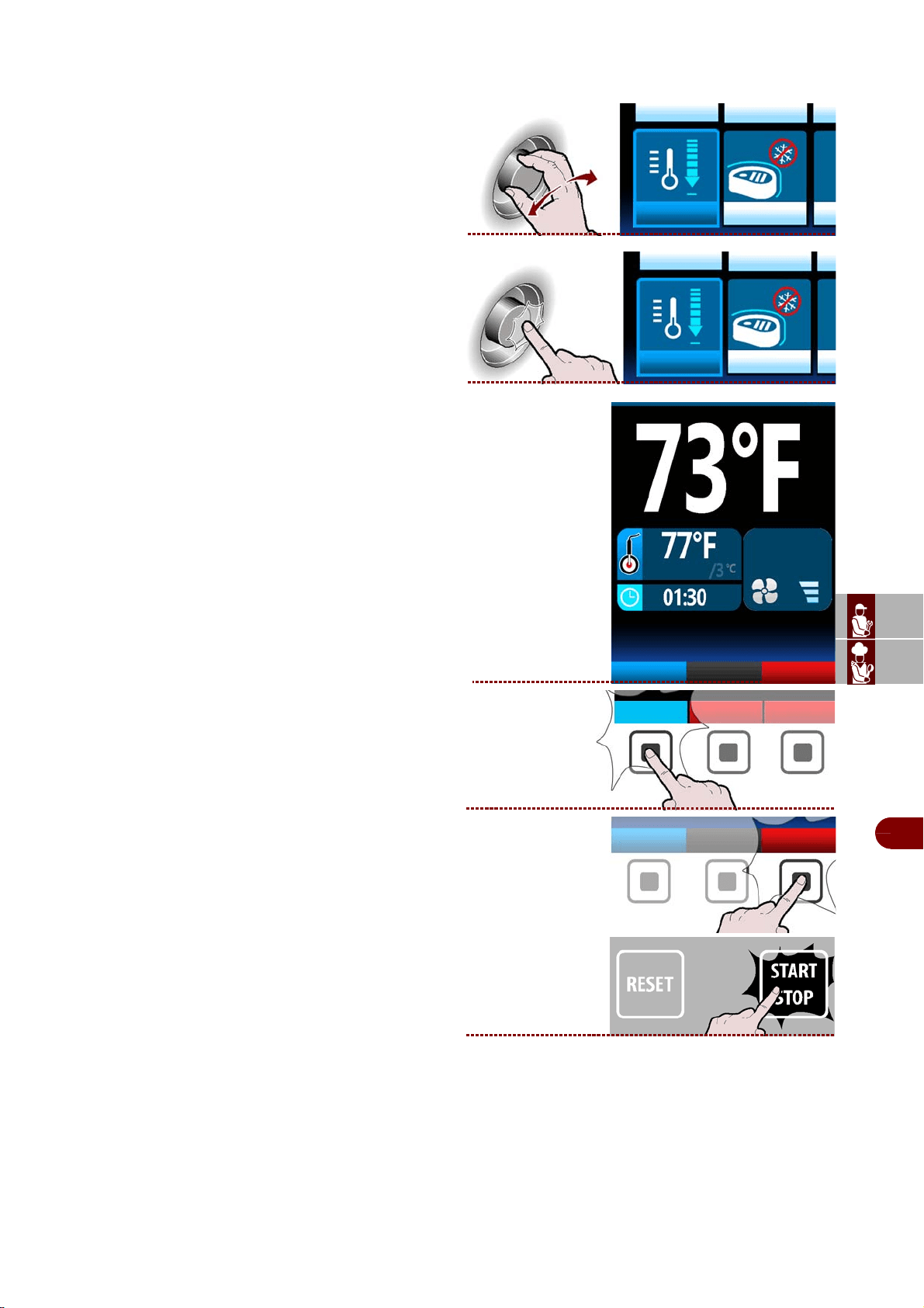
Chamber temperature
1–Select the "chamber temperature" zone using the
knob.
>>
2–Press the knob to confirm the selected zone. >>
3–To modify the chamber temperature, turn the
knob until the value required is displayed. >>>
4–Press the knob to confirm the selected value.>>
Chilling time or core temperature
1–elect either the "chilling time" or the "core temper-
ature" zone using the knob.
>>
2–Press the knob to confirm the selected zone. >>
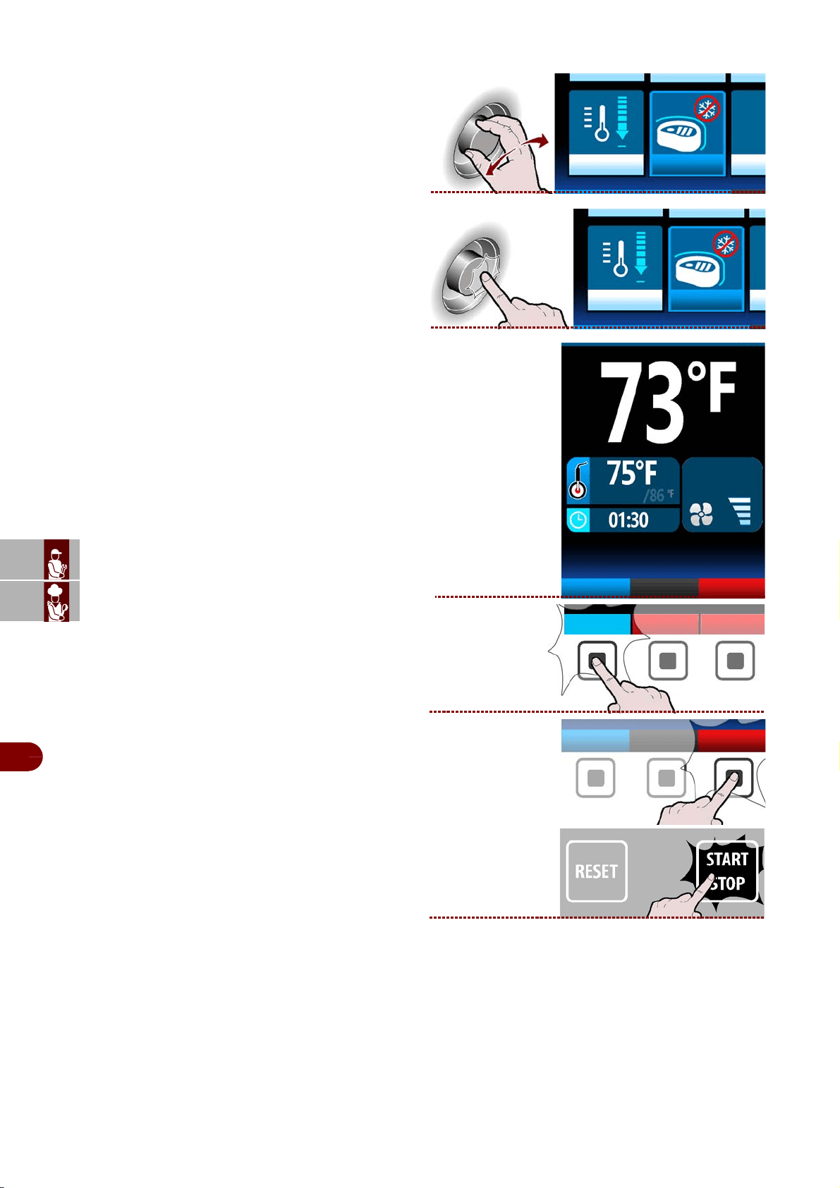
For example, if a user selects the "chilling time" func-
tion and then selects "core temperature", the first
function is cancelled, or vice-versa.
3–To modify the value selected ("chilling time" or
"core temperature"), turn the knob until the value re-
quired is displayed. >>>
4–Press the knob to confirm the selected value.>>
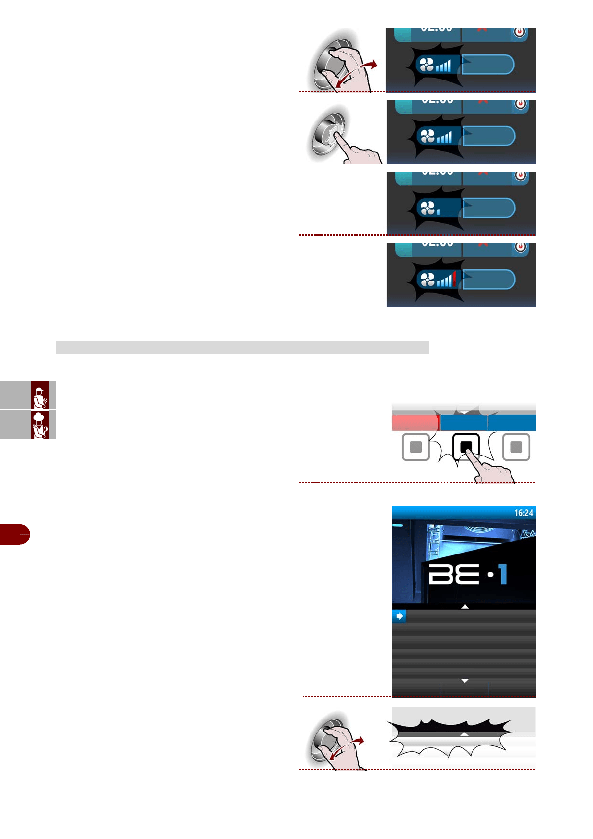
Fan speed
1–Select the "fan speed" zone using the knob.
>>
2–Press the knob to confirm the selected zone. >>
phase 1/2
phase 1/2
ES
CAN
DE
US
IT
3299702_rev.2.fIDM
English
-
20
-
Use and installation manual
3–To modify the cooking fan speed, turn the knob to
increase or reduce the number of notches on the
graduated scale. >>>
4–Press the knob to confirm the selected value. >>
The symbol shows that the cooling fan speed is on
the minimum setting. >>>
The symbol shows that the cooling fan speed is on
the maximum setting. >>>
These programmes are manufacturer recommended work cycles.
During the cycle the parameters can be viewed, but not modified.
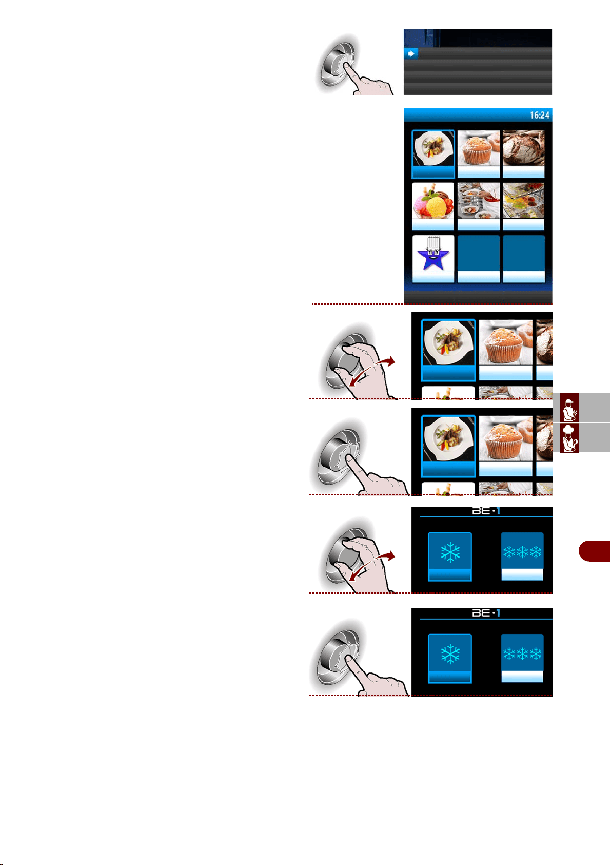
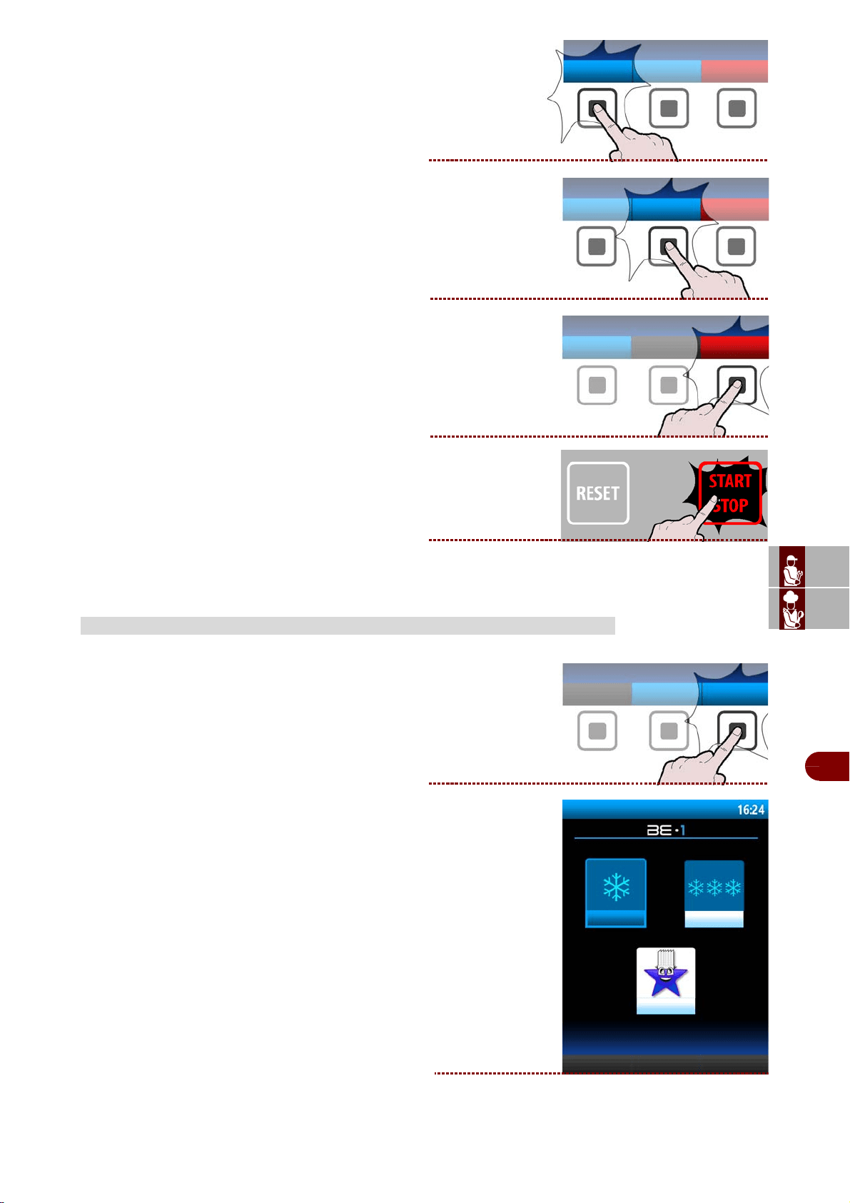
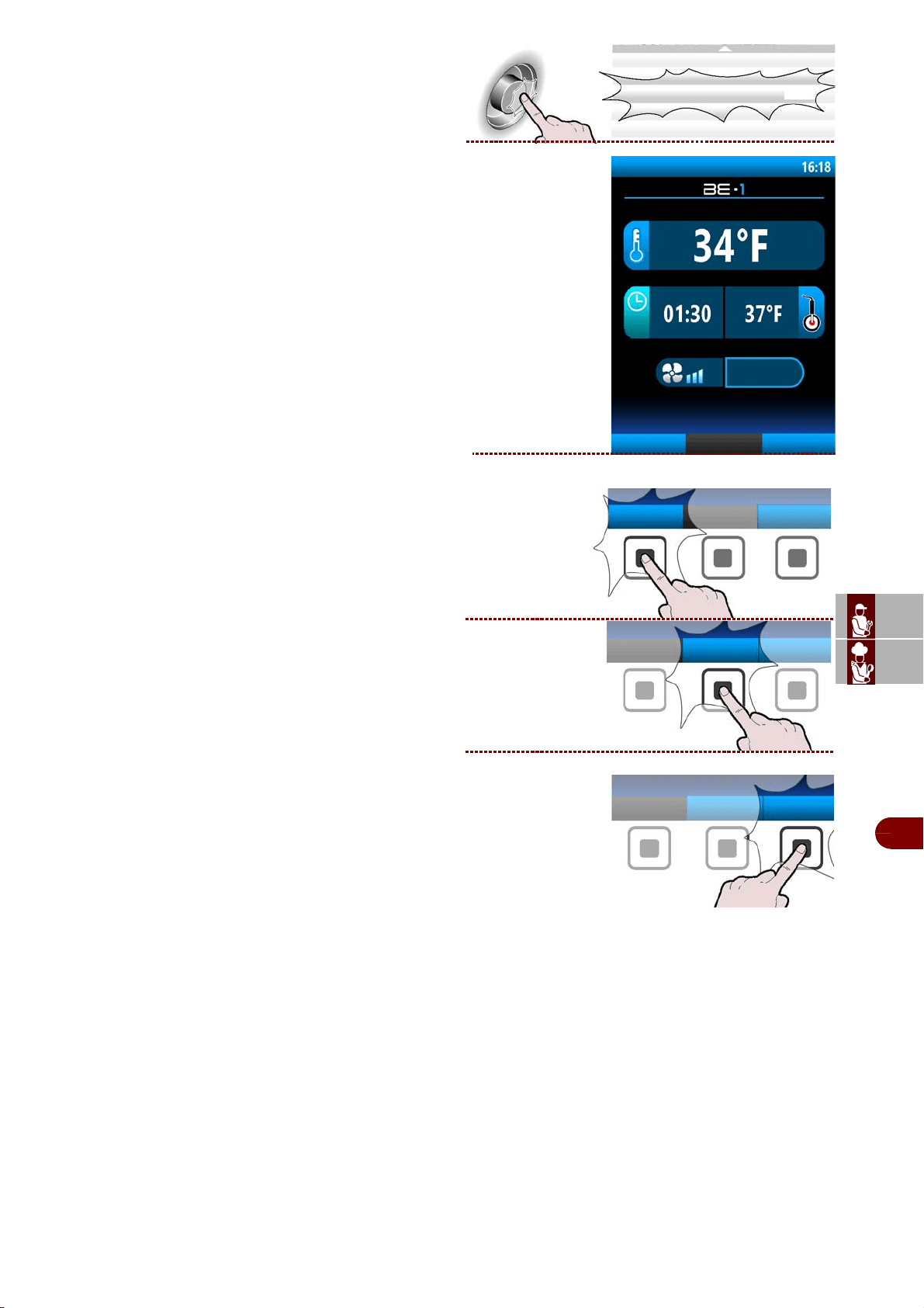
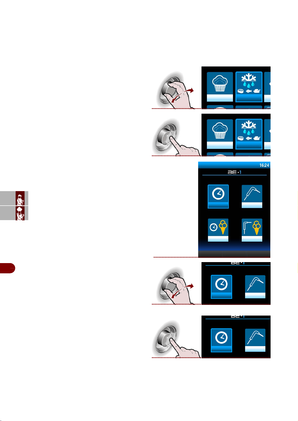
Proceed as follows.
1–From the main functions screen (blast chiller
home page), press the button to access the menù.
>>>
The display will show page. >>>
2–Select the "automatic programs" function using
the knob. >>>
AUTOMATIC PROGRAMS
phase 1/2
phase 1/2
phase 1/2
phase 1/2
menù
automatic programs
special functions
user programs
settings
service
haccp
data loading/downloading
automatic programs
ES
CAN
DE
US
IT
3299702_rev.2.fIDM
English
-
21
-
Use and installation manual
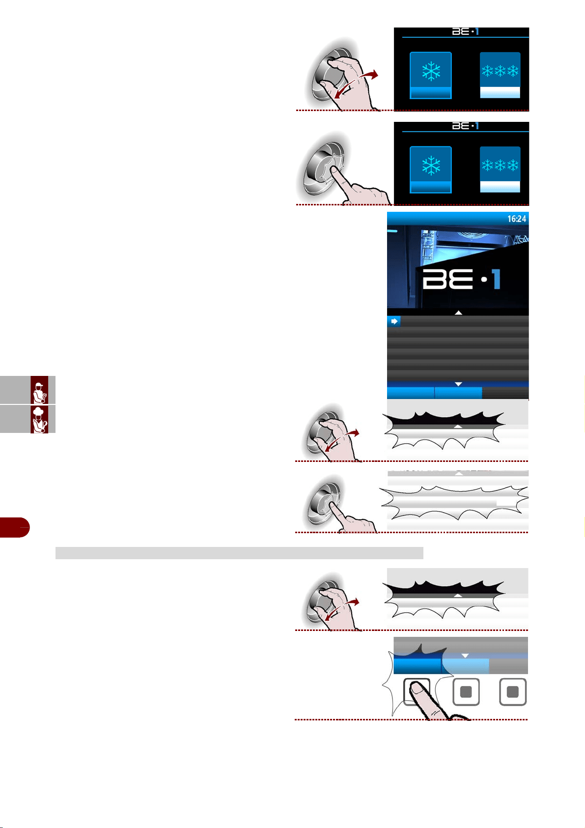
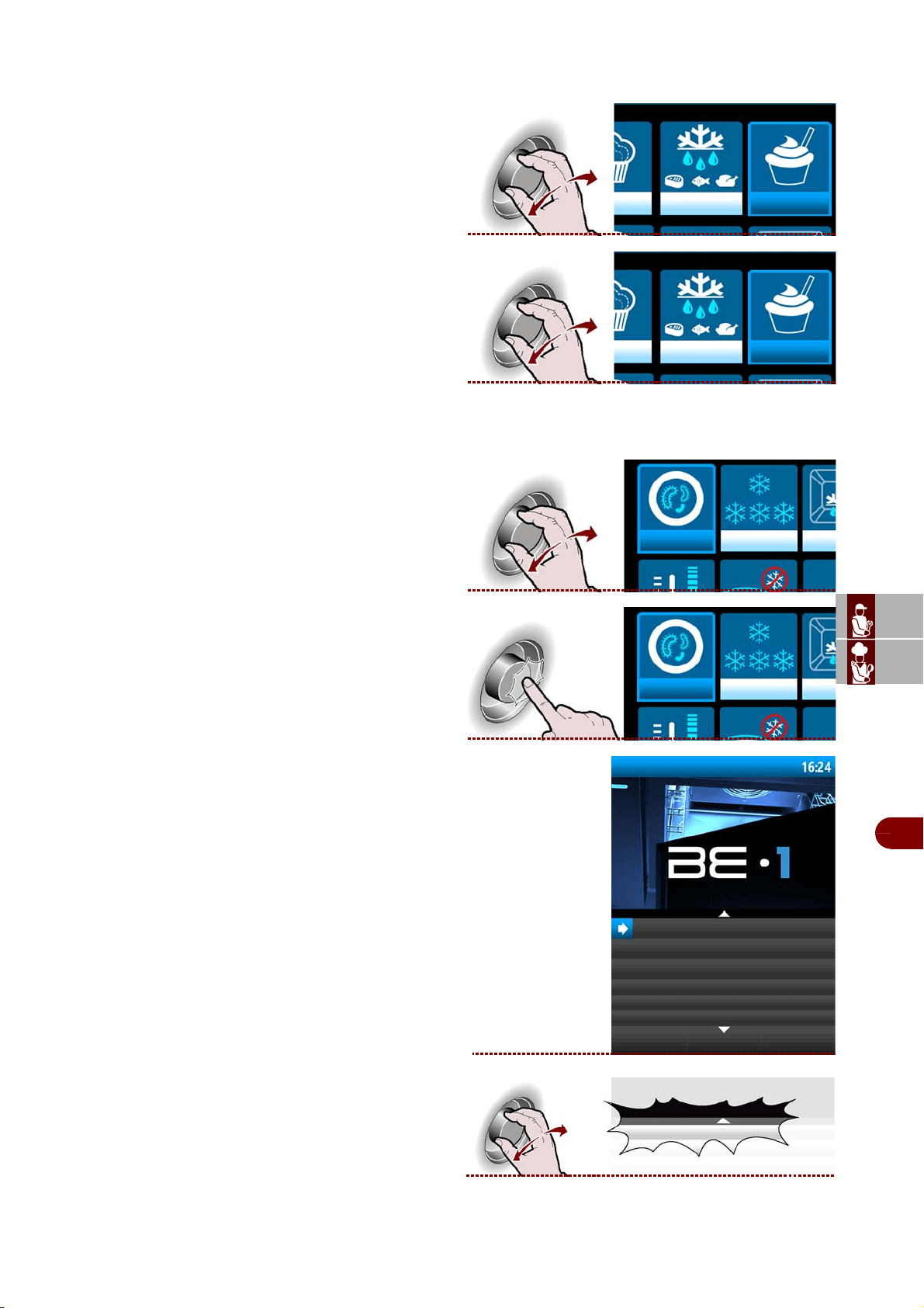
3–Press the button to confirm the selected function.
4–The display will show page. >>>
5–Select the desired sector by rotating the knob. >
6–Press the knob to confirm the selected choice. >
7–Select the type of desired cycle by rotating the
knob. >>>
8–Press the knob to enter into the selected type of
cycle. >>>
automatic programs
automatic programs
catering
pastry
bakery
ice cream
banqueting vacuum
favorite
catering pastry
catering pastry
catering + catering -
catering + catering -
ES
CAN
DE
US
IT
3299702_rev.2.fIDM
English
-
22
-
Use and installation manual
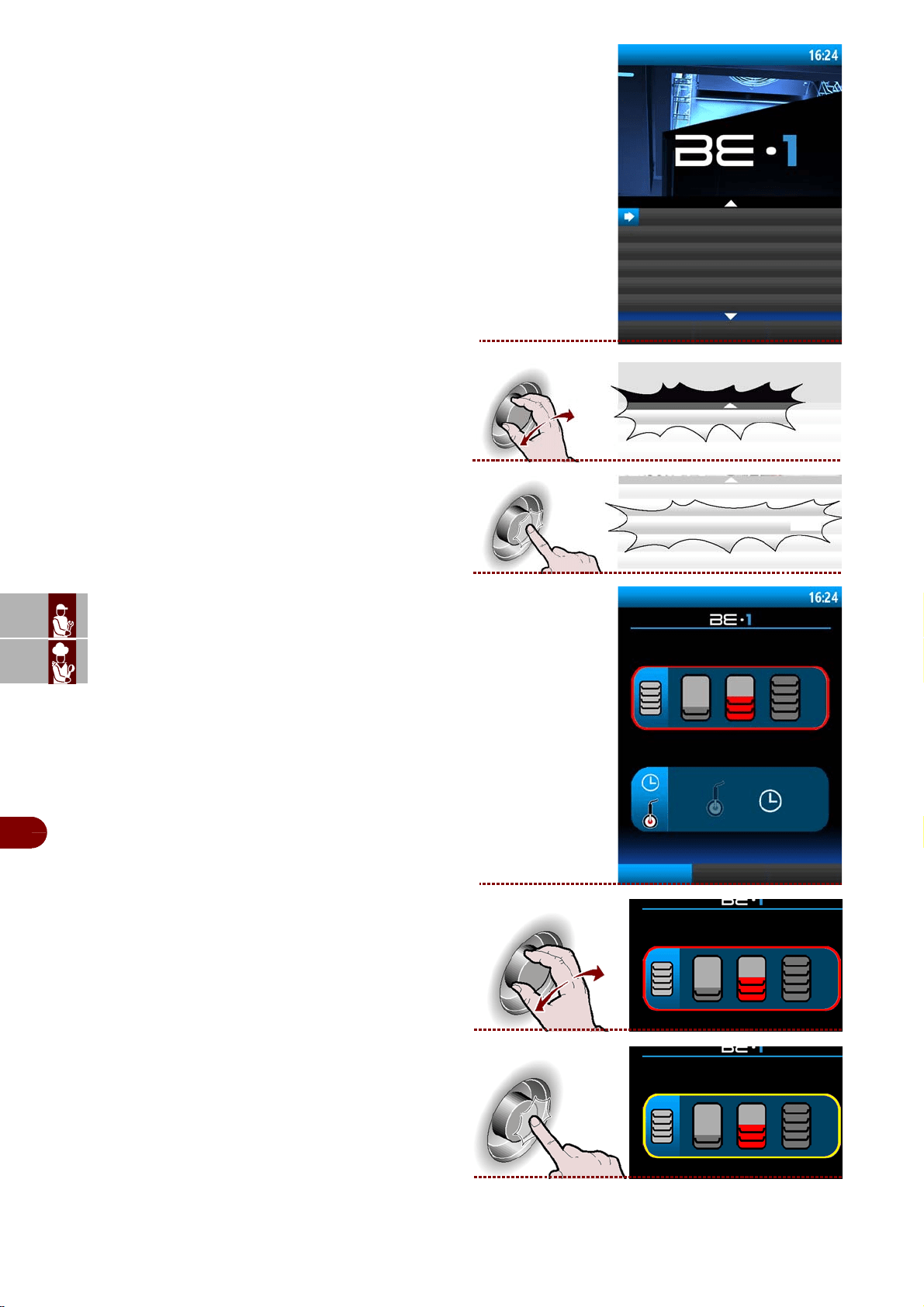
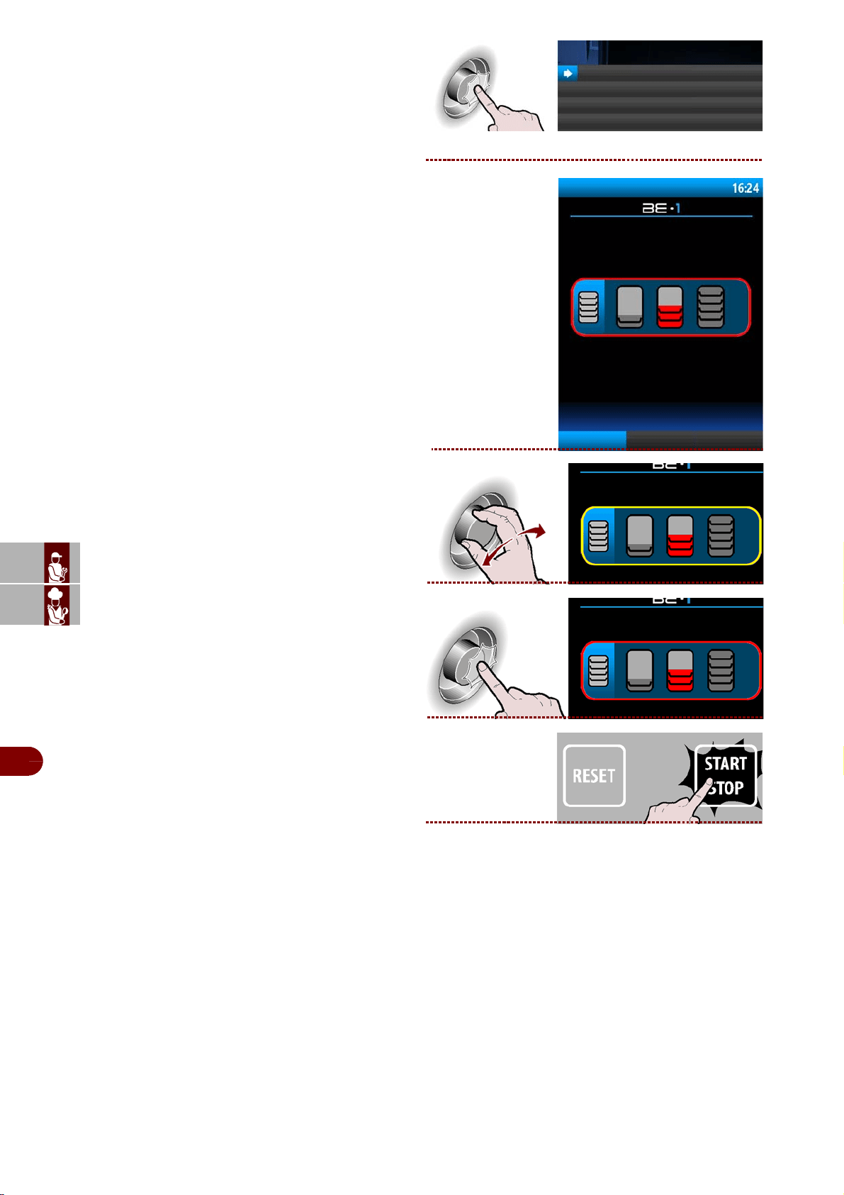
9–The display will show page. >>>
10–Select the desired cycle by rotating the knob. >
11–Press the knob to activate the selected cycle. >
12–The display will show page. >>>
13–Select the quantity of load to be treated. >>>
14–Press the knob to confirm the selected choice.
catering +
BANQUETING
MEAT
LASAGNE
WALNUTS VEAL
HOT PASTRY
DRY PASTRY
MEAT
MEAT
catering + MEAT
add to
favourite
ES
CAN
DE
US
IT
3299702_rev.2.fIDM
English
-
23
-
Use and installation manual
15–Select the quantity of load to be treated, mini-
mum, medium, maximum. >>>
16–Press the knob to confirm the selected choice.
17–Select the desired type of cycle control. >>>
18–Press the knob to confirm the selected choice.
19–Select the desired type of cycle control, with
probe or by time. >>>
20–Press the knob to confirm the selected choice.
-make it a favourite program
To set this as a favourite program, press the"set
as favourite" button and proceed as described on
page 13 (alphanumeric mode).
21–Press the button to start the selected cycle.
>>
set as
favourite
ES
CAN
DE
US
IT
3299702_rev.2.fIDM
English
-
24
-
Use and installation manual
22–The display will show page. >>>
During the cycle it is possible:
-to view the default parameters.
Note: the parameters cannot be modified.
-select the oven function
.
-to stop the cycle.
23–
Cycle ended, automatic conservation phase.
The display will show page. >>>
phase 1/3
oven
display set
data
meat
display set
data
oven
fase 3/3
forno
modifica
parametri
defrost
CICLO TERMINATO: CONSERVAZIONE ATTIVA
carne
fase 3/3
oven
modify
parameters
defrost
CYCLE COMPLETED: STORAGE IN PROGRESS
ES
CAN
DE
US
IT
3299702_rev.2.fIDM
English
-
25
-
Use and installation manual
During conservation it is possible:
-o view and modify the default parameters (see
page 18).
Note: the modified parameters will be saved
only for the cycle in progress.
-to activate a manual defrost.
If not required, manual defrosting is not per-
formed.
-select the oven function
.
-to stop the cycle.
Proceed as follows.
1–From the main functions screen (blast chiller
home page), press the button to access the “user
programs” . >>>
2–The display will show page. >>>
USER PROGRAMS
modify
parameters
defrost
oven
user
programs
user programs
programs +
favorite
programs -
ES
CAN
DE
US
IT
3299702_rev.2.fIDM
English
-
26
-
Use and installation manual
3–Select the type of desired cycle with the knob
>>>
4–Press the knob to enter into the selected type of
cycle. >>>
5–The display will show page. >>>
6–Select the desired cycle by rotating the knob. >>
7–Press the knob to activate the selected cycle. >>
1–Select the name of the program using the knob.
>>>
2–Press the button.
>>
EDIT USER PROGRAMS
programs + programs -
programs + programs -
programmi utente +3°C
CARNE
opzioni
nuovo
programma
PESCE
user programs +
MEAT
options
new
program
FISH
MEAT
MEAT
;MEAT
options
ES
CAN
DE
US
IT
3299702_rev.2.fIDM
English
-
27
-
Use and installation manual
3–The display will show page. >>>
4–Select the function of interest from the list, using
the knob. >>>
5–Press the knob to confirm the selected function
. >>>
-RENAME: it is used to assign a new name to the selected program (see page 13).
-MODIFY/DISPLAY PHASES: used to display and/or modify the stages of the se-
lected program (see page 18).
-
ADD TO FAVOURITES
: used to save the chosen program in the favourites category
-COPY: it is used to "copy-paste" the selected program and rename it (see page
13).
-DELETE : Used to delete the selected program.
user programs +
meat
rename
edit/display the stages
add to favourites
copy
delete
rename
rename
ES
CAN
DE
US
IT
3299702_rev.2.fIDM
English
-
28
-
Use and installation manual
1–Press the button. >>>
2–Enter the name of the new program (see page 13)
The display will show page. >>>
3–Select the name of the program using the knob .
>>>
4–Press the button.
>>
5–The display will show page. >>>
6–Select the function of interest from the list, using
the knob. >>>
CREATING A NEW USER PROGRAM
new
program
user programs +
MEAT
options
new
program
FISH
FISH
options
user programs +
meat
rename
edit/display the stages
add to favourites
copy
delete
edit/display the stages
ES
CAN
DE
US
IT
3299702_rev.2.fIDM
English
-
29
-
Use and installation manual
7–Press the knob to confirm the selected function.
>>>
8–The display will show page. >>>
Set all the characteristics of the new program (see
page 28).
9–When creating a new program, it may be neces-
sary to program in more than one stage. To do this,
press the button.
>>>
10–Also may be necessary remove one or more
stages of the one program. >>>
11–When programming is complete, press the but-
ton to save the new program and return to the main
menu. >>>
edit/display the stages
phase 1/2
add stage
save
program
FISH
add stage
delete stage
save
program
ES
CAN
DE
US
IT
3299702_rev.2.fIDM
English
-
30
-
Use and installation manual
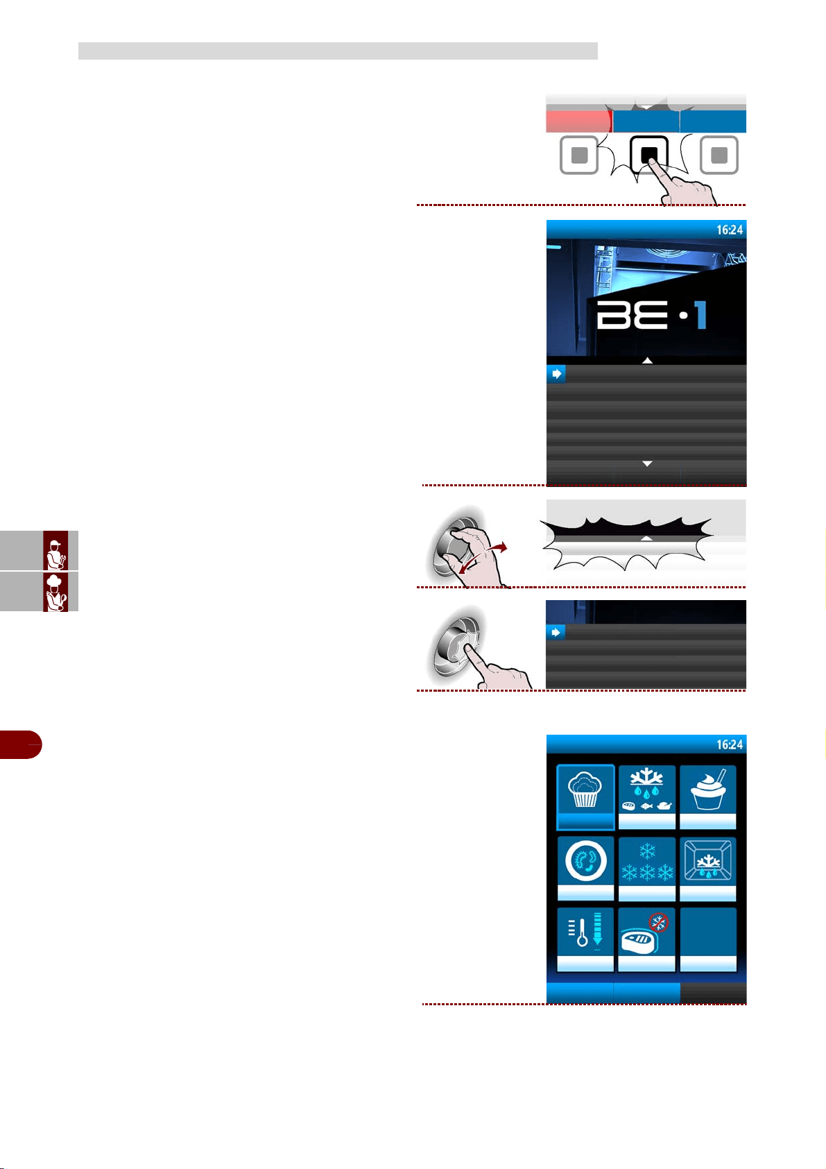
Proceed as follows.
1–From the main functions screen (blast chiller
home page), press the button to access the menu.
>>>
The display will show page. >>>
2–Select the "special functions" function using the
knob. >>>
3–Press the button to confirm the selected function.
4–The display will show page. >>>
SPECIAL FUNCTIONS
menù
automatic programs
special functions
data loading/downloading
settings
service
haccp
special functions
special functions
special functions
proving
thawing
yogurt box
parasites
storage
defrost
cooling
ifr
probe heating sanitation
ES
CAN
DE
US
IT
3299702_rev.2.fIDM
English
-
31
-
Use and installation manual
Leavening
The leavening and retarding cycles are automatic. During the cycle the parameters
can be modified to select the temperature or the time at which the food should be leav-
ened and ready for use.
The operator can decide to change only the end cycle date by acting on the date
shown on the screen of the cycle in progress, but only during the first phase (preser-
vation), easily scheduling the moment at which the product should be perfectly leav-
ened.
1–Select the chosen functionby rotating the knob.
>>>
2–Press the knob to confirm the selected choice
. >>>
-The display will show page .
3–
Press button to activate the selected cycle.
>>
leavening
leavening
leavening
leavening
stops leavening
ES
CAN
DE
US
IT
3299702_rev.2.fIDM
English
-
32
-
Use and installation manual
Thawing
The defrost cycles with probe or by time are automatic. During the cycle the parame-
ters can be modified and the temperature can be selected or the time at which the food
should be defrosted and ready for use.
In the event of time defrosting the operator can decide to change only the cycle end
date acting on the date on the screen of the cycle in progress. This action is valid only
if you are in the first phase (preservation).
1–Select the chosen functionby rotating the knob
. >>>
2–Press the knob to confirm the selected choice.
>>>
-The display will show page.
3–Select the type of desired cycle by rotating the
knob. >>>
4–Press the knob to enter into the selected nella tip-
ologia di type of cycle. >>>
Note: the cycle starts automatically.
thawing
thawing
thawing
time
probe
ice cream time
ice cream probe
time
probe
time
probe
ES
CAN
DE
US
IT
3299702_rev.2.fIDM
English
-
33
-
Use and installation manual
Yogurt box
Cycle dedicated to the preparation of yogurt.
1–Select the chosen function by rotating the knob.
>>>
2–Press the knob to confirm the selected choice.
>>>
Note: the cycle starts automatically.
Parasites
1–Select the chosen function by rotating the knob.
>>>
2–Press the knob to confirm the selected choice.
>>>
-The display will show page.
3–Select the desired cycle by rotating the knob.
>>>
yogurt box
yogurt box
parasites
parasites
parasites
anisakis 15h
anisakis 24h
opistorkis 24h
anisakis 15h
ES
CAN
DE
US
IT
3299702_rev.2.fIDM
English
-
34
-
Use and installation manual
4–Press the knob to confirm the selected function.
>>>
5–The display will show page. >>>
6–Select the quantity of load to be treated, mini-
mum, medium, maximum. >>>
7–Press the knob to confirm the selected choice .
>>>
8–
Press the key to start the program selected.
>>>
anisakis 15h
ANISAKIS 15h
add to
favourites
ES
CAN
DE
US
IT
3299702_rev.2.fIDM
English
-
35
-
Use and installation manual
Storage
It is used to store food at positive or negative temperature.
1–Select the chosen function by rotating the knob.
>>>
2–Press the knob to confirm the selected choice
. >>>
-The display will show page.
3–
Press button to activate the selected cycle.
>>>
storage
storage
storage
storage + storage -
ES
CAN
DE
US
IT
3299702_rev.2.fIDM
English
-
36
-
Use and installation manual
Defrost
It is used to optimise the operation of the blast chiller at the next cycle.
1–Select the chosen functionby rotating the knob .
>>>
2–Press the knob to confirm the selected choice
. >>>
-The display will show page.
3–
Press button to activate the selected cycle.
>>>
Defrost
Defrost
phase 1/2
Defrost
ES
CAN
DE
US
IT
3299702_rev.2.fIDM
English
-
37
-
Use and installation manual
Cooling
It is advisable to run a cooling cycle prior to selecting any slaughter cycle.
1–Select the chosen functionby rotating the knob .
>>>
2–Press the knob to confirm the selected choice
>>>
3– The display will show page. >>>
Note: the cycle starts automatically.
During the cycle it is possible:
-to view and modify the default parameters (see
page 18).
Note: the modified parameters will be saved
only for the cycle in progress.
-select the oven function.
.
-to stop the cycle. .
Cooling
Cooling
phase 1/2
oven
modify
parameters
modify
parameters
oven
ES
CAN
DE
US
IT
3299702_rev.2.fIDM
English
-
38
-
Use and installation manual
Ifr
1–Select the chosen functionby rotating the knob
.>>
2–Press the knob to confirm the selected choice
.>>
3– The display will show page. >>>
Note: the cycle starts automatically.
During the cycle it is possible:
-to view and modify the default parameters (see
page 13).
Note: the modified parameters will be saved
only for the cycle in progress.
-select the oven function
.
to stop the cycle .
ifr
ifr
fase 1/1
oven
modify
parameters
modifica
parametri
oven
ES
CAN
DE
US
IT
3299702_rev.2.fIDM
English
-
39
-
Use and installation manual
The cycle can be controlled automatically (AUTO) or by the operator , either timed or
with core probe (MANUAL).
The default unit controls the cycle in automatic mode (AUTO).
Proceed as follows.
1–From the screen main functions (home page ov-
en), press the button to enter the mode blast chiller
. >>>
2–From the main functions screen (blast chiller
home page), press the button to access the menu.
>>>
The display will show page. >>>
3–Select the "settings" function using the knob. >>
4–Press the button to confirm the selected function.
>>>
SETTINGS
blast chiller
menù
automatic programs
special functions
settings
service
haccp
data loading/downloading
settings
settings
ES
CAN
DE
US
IT
3299702_rev.2.fIDM
English
-
40
-
Use and installation manual
5–The display will show page. >>>
6–Press the knob to confirm the selected choice. >
7–Press the knob to confirm the selected choice. >
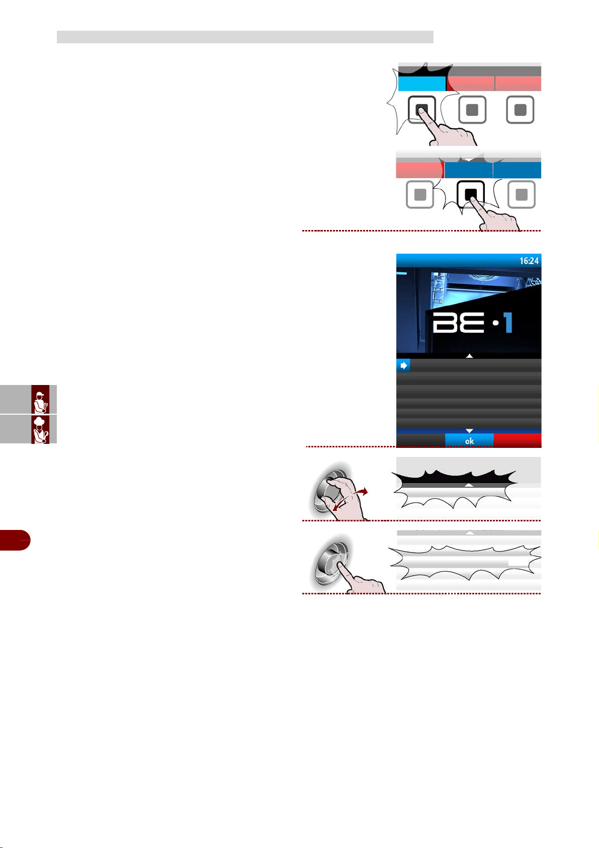
Proceed as follows.
1–From the screen main functions (home page ov-
en), press the button to enter the mode blast chiller.
2–From the main functions screen (blast chiller
home page), press the button to access the menu.
>>>
SERVICE
wednesday, 30.04.2014
probe control automatic
probe control
probe control
automatic
manual
blast chiller
menù
ES
CAN
DE
US
IT
3299702_rev.2.fIDM
English
-
41
-
Use and installation manual
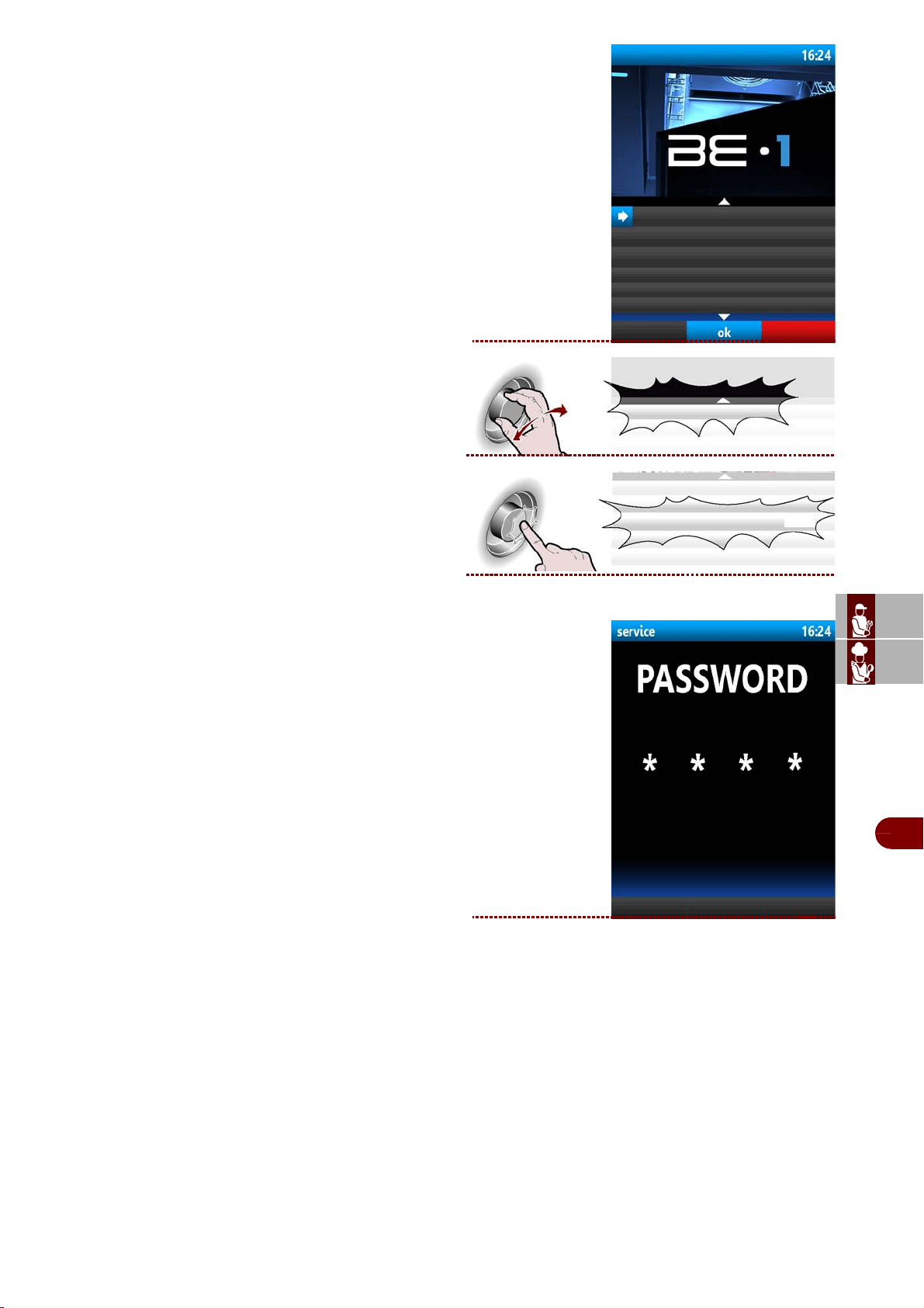
The display will show page. >>>
3–Select the "service" function using the knob. >>>
4–Press the button to confirm the selected function.
The display will show page. >>>
-Turn the knob to enter the password supplied by
the manufacturer.
-Press the knob to confirm.
automatic programs
special functions
settings
service
haccp
data loading/downloading
service
service
ES
CAN
DE
US
IT
3299702_rev.2.fIDM
English
-
42
-
Use and installation manual
Proceed as follows.
1–From the screen main functions (home page ov-
en), press the button to enter the mode blast chiller.
>>>
2–From the main functions screen (blast chiller
home page), press the button to access the menu .
>>>
The display will show page . >>>
3–Select the "haccp" function using the knob .
>>>
4– Press the button to confirm the selected func-
tion. >>>
HACCP
blast chiller
menù
automatic programs
settings
service
haccp
data loading/downloading
special functions
haccp
haccp
ES
CAN
DE
US
IT
3299702_rev.2.fIDM
English
-
43
-
Use and installation manual
The display will show page . >>>
The page is used to display the effective (and not me-
asured) Blast chilling data and the alarms that have
intervened..
5–Press the knob to change the day (month or
year). . >>>
6–Turn the knob to set the day (month or year).
>>>
7–Press the knob to confirm the selected value .
>>>
8–Turn the knob to select "Acquisitions" .
>>>
9–Press the knob to access the data.
>>>
10–Press the knob to confirm the selected function.
. >>>
11–Press the button to return to the previous page.
12–Press the button to display the alarms inter-
vened >>>
haccp
day
18
acquisitions
cooling
start
11:39 11:40
month
year
12 2017
stop
11:40 11:40
11:42 11:46
11:54 11:58
ifr
ifr
ifr
display alarms
haccp
day
18
month year
12 2017
haccp
giorno
16
month year
12 2017
haccp
day
16
month year
12 2017
acquisitions
haccp
day
month year
acquisitions
haccp
day
month year
ifr
display
alarms
ES
CAN
DE
US
IT
3299702_rev.2.fIDM
English
-
44
-
Use and installation manual
Proceed as follows.
1–From the screen main functions (home page ov-
en), press the button to enter the mode blast chiller.
>>>
2–From the main functions screen (blast chiller
home page), press the button to access the menù
. >>>
Sul display compare la pagina. >>>
3–Select the "Data loading/unloading" function us-
ing the knob . >>>
4–Press the button to confirm the selected function .
>>>
The display will show page. >>>
The page is used to download user programs or
HACCP data from the blast chiller to an external
memory unit or to upload the user programs from an
external memory unit.
DOWNLOAD/UPLOAD DATA
blast chiller
menù
automatic programs
special functions
settings
service
haccp
download/upload data
download/upload data
download/upload data
upload user programs
download user programs
upload HACCP data
ES
CAN
DE
US
IT
3299702_rev.2.fIDM
English
-
45
-
Use and installation manual
5–Select the "download user programs" function us-
ing the knob. >>>
6–Press the button to confirm the selected function.
>>>
7–Press the “select all” button to select all the Blast
chilling programs to be uploaded and/or downloaded
t >>>
Alternatively, select the individual programs to be up-
loaded/downloaded.
8–Press the button to start the operation . >>>
Depending on the amount of data to downloaded/up-
loaded, the operation can take several minutes.
Should the machine be disconnected over long periods, follow the instructions below
to maintain the appliance in good condition:
1–Turn the mains switch OFF.
2–Disconnect the plug.
3–Empty the appliance and clean it in accordance with the instructions given in the
chapter "CLEANING".
4–Leave the door ajar to prevent a bad smell.
5–Cover the compressor unit with a nylon cloth to protect it from dust.
Important
In case of appliances with remote control, if you decide to turn it off, remember
to put the switch off also in the remote control.
LENGTHY DOWNTIMES OF APPLIANCE
download user programs
download user programs
select all
menù
perform
ES
CAN
DE
US
IT
3299702_rev.2.fIDM
English
-
46
-
Use and installation manual
Keep the appliance at peak efficiency by carrying out the scheduled servicing proce-
dures recommended by the constructor. Proper servicing will allow the best perform-
ance, a longer working life and constant maintenance of safety requirements.
By stainless steel we mean INOX AISI 304 steel.
We recommend following the instructions below for the mainte-
nance and cleaning of stainless-steel parts.
This is of the utmost importance to ensure the non-toxicity and
complete hygiene of the processed foodstuffs.
Stainless-steel is provided with a thin oxide layer which prevents
it from rusting.
However, some detergents may destroy or affect this layer,
therefore causing corrosion.
Before using any cleansing product, ask your dealer about a
neutral chloriness cleansing product, as to avoid steel corro-
sions.
If the surface has been scratched polish it with fine STAIN-
LESS-STEEL wool or a synthetic-fibre abrasive sponge. Always
rub in the direction of the silking.
Caution - warning
Never use iron wool for cleaning STAINLESS STEEL. Fur-
thermore, avoid leaving iron wool on the appliance surface
as tiny iron deposits may cause the surface to rust by con-
tamination and affect the hygiene of the appliance.
The information and instructions in this section are re-
served for specialised personnel, authorised to oper-
ate on the equipment components.
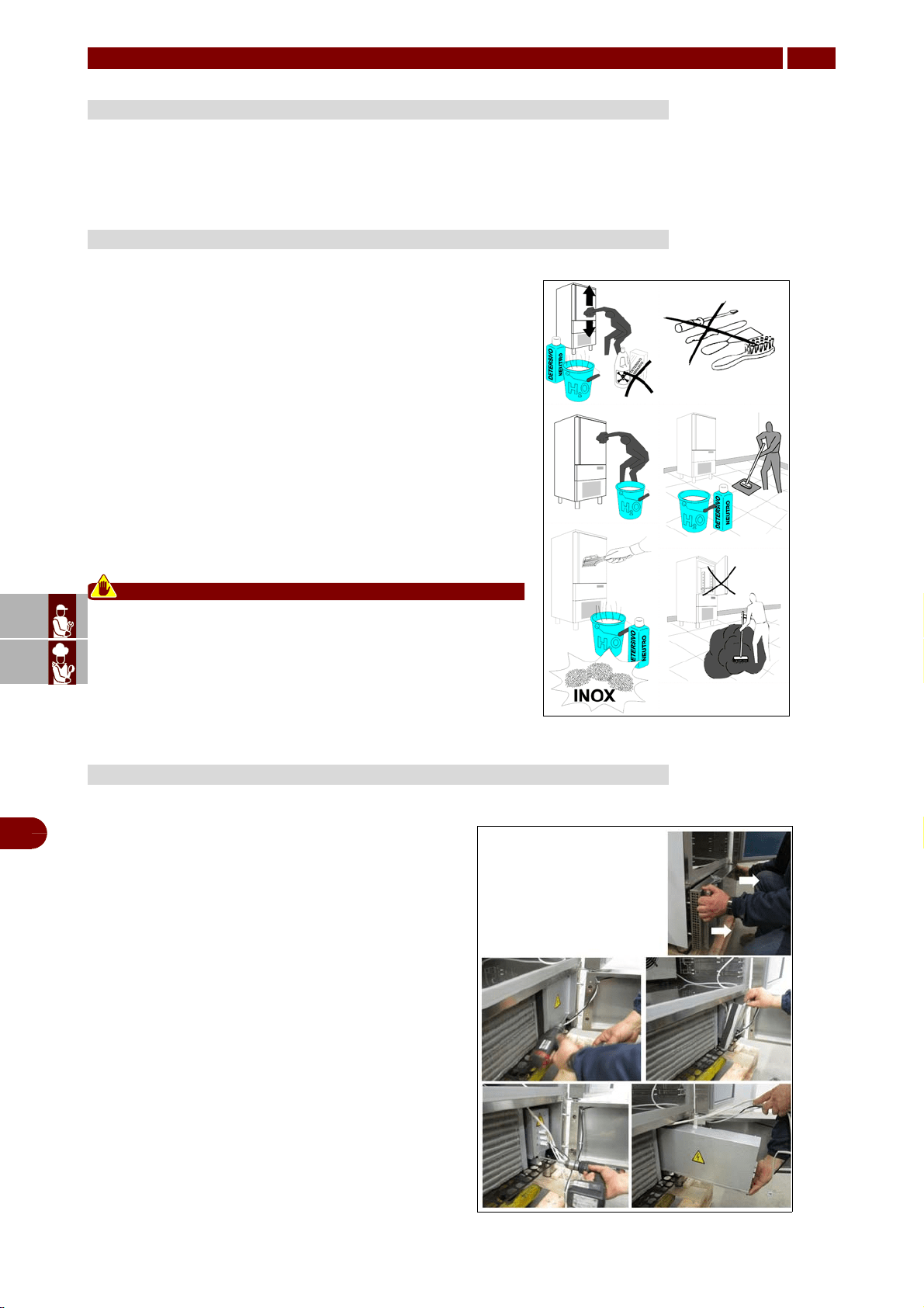
–Turn the mains switch OFF.
–Disconnect the plug.
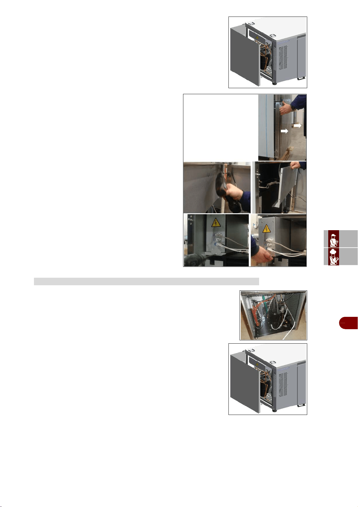
To be able to access the electric picture:
Mod. B151MU - B152MU
–Unhook the front guard, pulling it towards you.
–Remove the closing panel screws.
–Remove the closing panel.
–Remove the electrical panel locking screw.
–Move the electrical panel box along the slide.
SERVICING
5
RECOMMENDATIONS FOR SERVICING
STAINLESS-STEEL MAINTENANCE
MAINTENANCE OF PANEL BOARD
ES
CAN
DE
US
IT
3299702_rev.2.fIDM
English
-
47
-
Use and installation manual
Mod. B151HU
Remove the side panel, undoing the screws.
Mod. B1101SU
–Unhook the front guard, pulling it towards you.
–Remove the closing panel screws.
–Remove the closing panel.
–Remove the electrical panel locking screw.
–Move the electrical panel box along the slide.
Mod. B151MU – B152MU - B1101SU
–To access the condensing system, remove the rear protective grille, undo-
ing the screws.
Mod. B151HU
–To access the condensing system, remove the side panel, undoing
the screws.
CONDENSING SYSTEM MAINTENANCE
ES
CAN
DE
US
IT
3299702_rev.2.fIDM
English
-
48
-
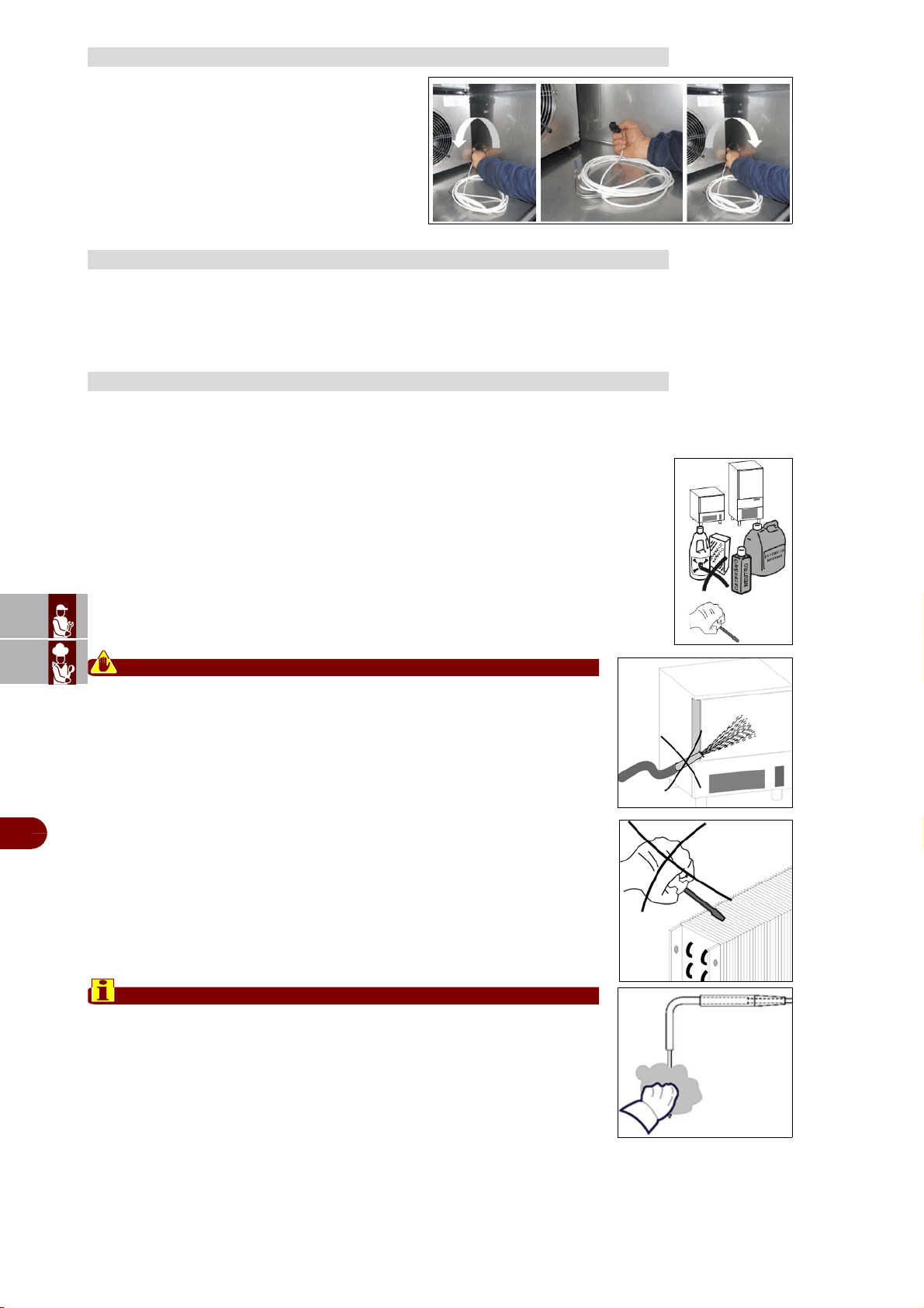
Use and installation manual
–Turn left completely unscrewing the connector
to disconnect the cable of the core probe.
–Replace the core probe by screwing the con-
nector fully.
Keep the appliance at peak efficiency by carrying out the scheduled servicing proce-
dures recommended by the constructor. Proper servicing will allow the best perform-
ance, a longer working life and constant maintenance of safety requirements.
Clean inside the cooling cabinet daily.
Both the cabinet and all the internal components have been designed and shaped to
allow washing and cleaning all parts easily.
–Before cleaning, defrost the appliance and remove the internal drain.
–Disconnect the master switch.
–Clean all components (stainless-stell, plastic or painted parts) with lukewarm water
and detergent.
–Then rinse and dry without using abrasives or chermical solvents.
Caution - warning
Do not wash the appliance by spraying high-pressure water on the ma-
chine.
Do not rinse with sharp or abrasive tools, especially the evaporator
–You may clean inside the evaporator after loosening the knobs and rotat-
ing the protection component..
–Wash the door gasket with water. Accurately dry with a dry cloth. We rec-
ommend wearing protecting gloves throughout the operations.
–Hand-wash the probe using lukewarm water and a mild detergent or prod-
ucts with biodegradability higher than 90%. Rinse with water and sanitary
solution.
Do not use detergents containing solvents (such as trichloroethylene, etc)
or abrasive powders.
Important
Do not use hot water to wash the probe.
REPLACEMENT CORE PROBE
RECOMMENDATIONS FOR SERVICING
CLEANING THE CABINET
ES
CAN
DE
US
IT
3299702_rev.2.fIDM
English
-
49
-
Use and installation manual
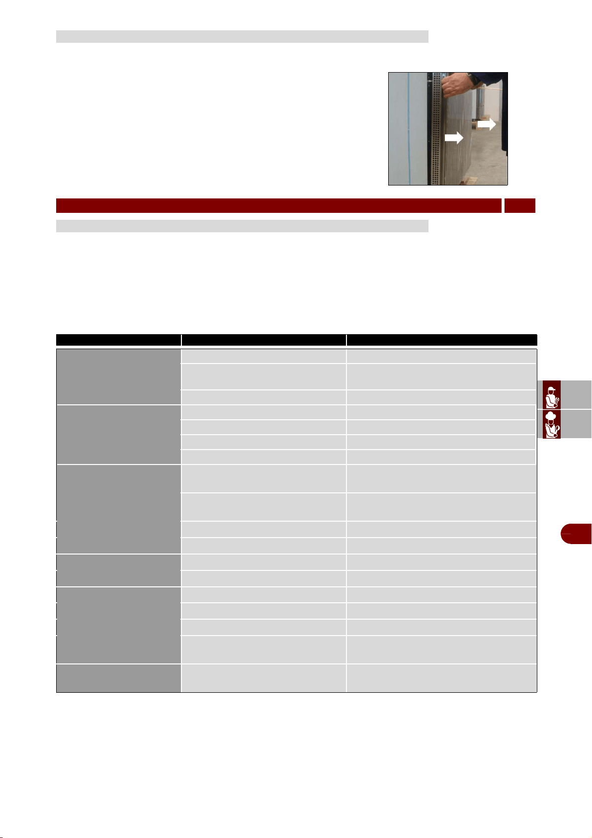
The air condenser should be kept clean to ensure the appliance's perfor-
mance and efficiency, as air should freely circulate inside the appliance.
The condenser should therefore be cleaned every 30 days, using non-
metal brushes to remove all dust and dirt from condenser blades.
–Access to the condenser is from the front.
–Unhook the front guard, pulling it towards you.
The appliance has been tested before being put into service.
The information provided below is intended to assist in the identification and correction
of any anomalies and malfunctions which might occur during use.
The user can solve some of these problems himself, but for others specific technical
knowledge or skill is required, and so they must only be carried out by qualified staff
with recognised experience acquired in the specific sector of operation.
CLEANING THE AIR CONDENSER
FAULT
6
TROUBLESHOOTING
Fault Remedy Remedy
The display board does
not switch on
No power supply Check the connection to the power mains
Blown fuse Replace fuses (qualified technician)
Loosened connections Check connection fitting
Compressor failure
High and Low-pressure switch on Qualified technician required
Clicker on Qualified technician required
Contactor failure Qualified technician required
Compressor thermal relay on Qualified technician required
The compressor is work-
ing but the cabinet is not
cooling
Frosted evaporator
Open the door and carry out the defrost
cycle
No coolant inside the refrigerating
system
Qualified technician required
Delivery solenoid valve failure
Qualified technician required
Condenser dirty
Clean the condenser
Evaporator fans are not
working
Fan failure or short-circuit
Qualified technician required
Door micro failure
Qualified technician required
The condenser fans do
not work
Faulty pressure switch
Qualified technician required
Faulty fan
Qualified technician required
Faulty pick-up condenser
Qualified technician required
Lack of consent from compressor
solenoid switch
Qualified technician required
Lack of evaporator de-
frosting
Incorrect defrosting programming
Check the defrosting cycle programming
ES
CAN
DE
US
IT
3299702_rev.2.fIDM
English
-
50
-
Use and installation manual
If the problem or fault noticed is not amongst thoselisted in the table,
consult the "Key to Alarms" tableprovided below.
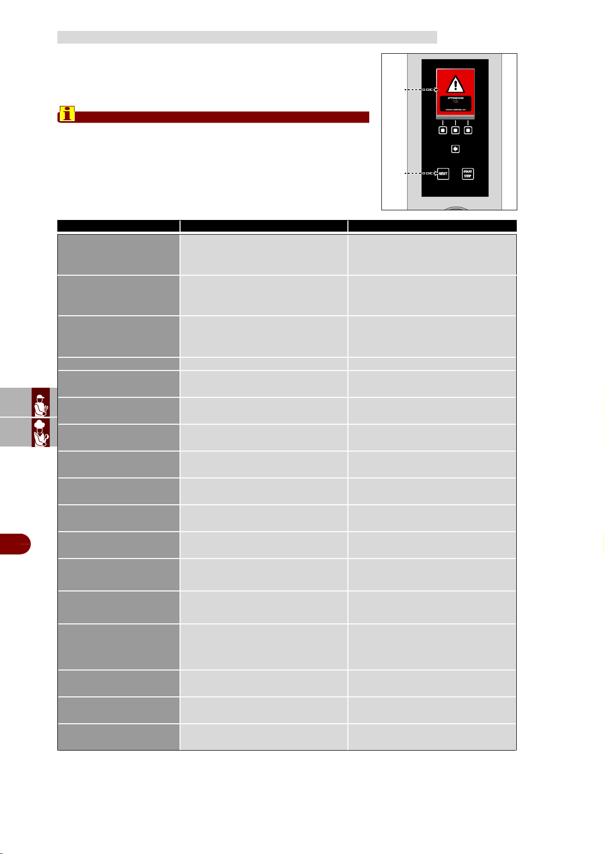
The information provided below s intended to identifythe alarm signals
which appear on the display (A).
Important
Press button (D) to reset the alarm.
TABLE OF ALARM INDICATIONS
Alarm/Event Cause Remedy
A01 - High temperature
alarm
(in conservation)
Room Temp above set value
If the temperature is not within the
specified range, apply to a qualified
technician
A02 - Low temperature
alarm
(in conservation)
Room Temp below set value
If the temperature is not within the
specified range, apply to a qualified
technician
A03 - Limit temperature
alarm
(in chilling/freezing)
Cell or core temperature higher than
the set value
If the temperature is not within the
specified range, apply to a qualified
technician
A04 - Room probe alarm
Room Probe interrupted Qualified technician required
A05 - Evaporator probe
alarm
Evap Probe interrupted Qualified technician required
A06 - Condenser probe
alarm
Cond Probe interrupted Qualified technician required
A07 - Dirty condenser
alarm
Condenser dirty Clean the condenser
A08 - Point needle probe
alarm
Needle Probe interrupted Qualified technician required
A09 - Underskin needle
probe alarm
Sub-dermis needle probe interrupted Qualified technician required
A10 - External needle
probe alarm
External needle probe interrupted Qualified technician required
A11 - Electr.box probe
alarm
Electrical panel probe interrupted Qualified technician required
A12 - Electr.box over-
temp. alarm
Electrical panel temperature higher
than the set value
Qualified technician required
A13 - Open door alarm
QC room door open
Door micro faulty
Close the door
Qualified technician required
A14 - BlackOut alarm
No power supply
When power is restored, check the
max. temperature reached inside the
room
A15 - High pressure
alarm
Intervention by high pressure switch Qualified technician required
A16 - Low pressure
alarm
Intervention by low pressure switch Qualified technician required
A17 - Compressor over-
load alarm
Compressor thermal relay on Qualified technician required
A
D
ES
CAN
DE
US
IT
3299702_rev.2.fIDM
English
-
51
-
Use and installation manual
Important
When handling and installing the appliance comply with the informationprovid-
ed by the constructor directly on the packaging, on the appliance and inthe in-
structions for use.
If necessary, the person authorised to carry out these operations must organi-
sea "safety plan" to protect the people directly involved.
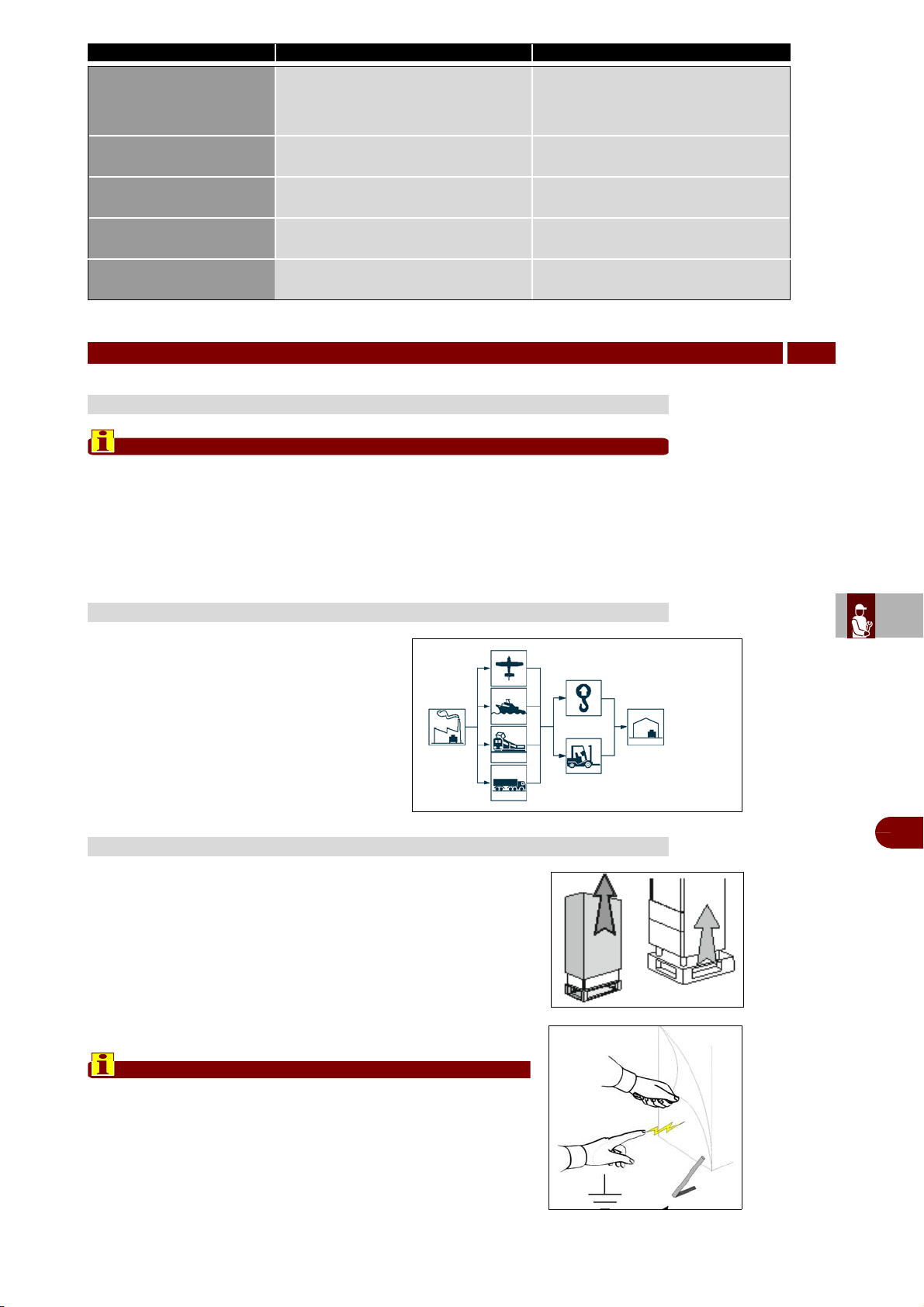
Different means of transport may be used,
dependingpartly on the destination.
The chart shows the most commonly used al-
terna-tives.
During transport, fix the packaging to the
means oftransport securely to prevent unde-
sirable shifting.
After removing the packaging, ensure the integrity of the equip-
ment and verify that all the parts or components are present and
that the characteristics and state correspond to the specifications
of the your order.
If not, please inform the retailer immediately.
Remove pvc protective film from all over the appliance.
Important
All the packing material must be disposed of in accordance
with the prevailing regulations in the country where the
equipment is used and in any case must not be dispersed
into the environment.
A18 - Mother board com-
munication alarm
Communication between the panel
board and the display board inter-
rupted
Qualified technician required
A19 - Mother board EEP-
ROM alarm
Data memory corrupted Qualified technician required
A20 - Panel board EEP-
ROM alarm
Data memory corrupted Qualified technician required
A21 - Needle probe 1
alarm
Needle Probe 1 interrupted Qualified technician required
A22 - Needle probe 2
alarm
Needle Probe 2 interrupted Qualified technician required
HANDLING AND INSTALLATION
7
RECOMMENDATIONS FOR HANDLING AND INSTALLATION
TRANSPORT
UNPACKING
Alarm/Event Cause Remedy
Lifting devices
means of transport
ES
CAN
DE
US
IT
3299702_rev.2.fIDM
English
-
52
-
Use and installation manual
The appliance must be installed and tested in full compliance with accident-prevention
regulations contained in national law and current guidelines.
Installers are to comply with any current local regulations.
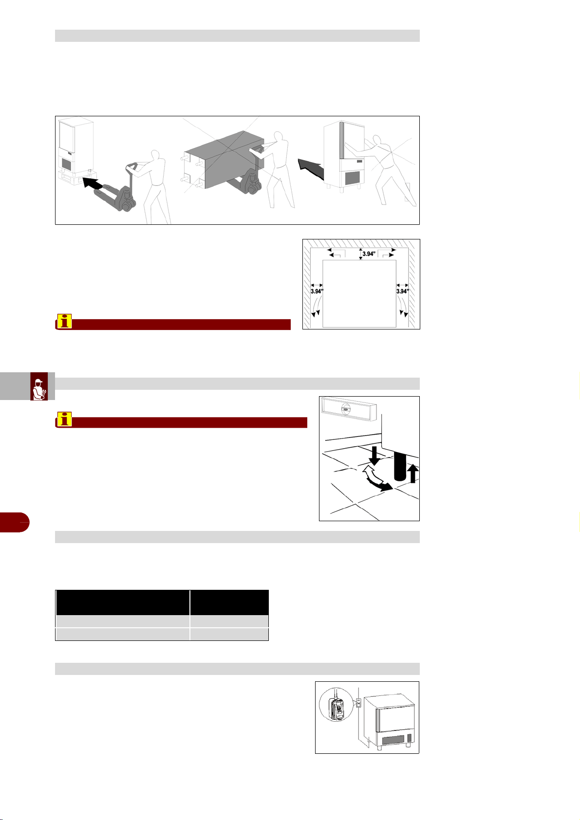
–Place the appliance onto the required working site.
–Avoid locations with exposure to direct sunlight.
–Do not place the appliance in hot, poorly-ventilated
rooms.
–
Leave a min. 3.94” clearance around the appliance on
the sides where air inlet and outlet are located.
Important
The appliance must be connected to FX ovens by
following the instructions in the instruction sheet supplied with KIT BE1+FX
Level the appliance by means of adjustable feet.
Important
If the appliance is not properly levelled the perform-
ance and condensate drain may be hampered.
Air-condenser units should not operate if room temperature is over 100°F. Above 89°F
maximum output is not guaranteed.
An omnipolar switch is to be installed before the appliance,
in compliance with the current regulations applied in the
country where the appliance is installed.
POSITIONING
LEVELLING
MAX ROOM TEMPERATURE
Model Air q.ty
[cfm]
B151MU - B152MU - B151HU 650
B1101SU 2060
WIRING

ES
CAN
DE
US
IT
3299702_rev.2.fIDM
English
-
53
-
Use and installation manual
The electrical connection is carried out from the rear part.
The electrical mains cables must be correctly sized and
selected based on the installation conditions.
The blast chiller have a junction box to allow the
conductors fitting.
The grounding cable is to be directly connected to a good
grounding system.
The guarantee will cease and the Manufacturer will not
be liable for any damage to appliances or operators aris-
ing from the non-compliance with the and tamperings to
any part of the appliance (electric, thermodynamic or hy-
draulic plant).
The equipment has a condensation collection tray. The tray is extractable from the
lower part of the equipment.
Should the appliance have been transported horizontally instead of a vertical position
DO NOT START THE APPLIANCE IMMEDIATELY. WAIT FOR AT LEAST 24
HOURS BEFORE OPERATING.
The manufacturer declines any responsibility and any warranty obligation if
damage occurs to the equipment imputable to transportation in a horizontal po-
sition.
Carry out the following checkings:
1–Outside temperatures must be included between 59°F and 100°F.
2–Turn on the appliance and wait 30 minutes before the use if the external tempera-
ture is “low”.
3–Check power input
4–Carry out at least one full quick cooling cycle
The following information concerns skilled staff only.
Door micro-switch: Prevents the appliance from working when the door is open
Overall protection fuses: Protect the whole power circuit from and short-circuits and
overloads
Compressor thermal relay: Operates in case of an overload or working failures
Motor-fan thermal relay: Operates in case of an overload or working failures
Safety pressure-switch: Operates in case of coolant over-pressure
Cabinet temperature control: Is run by NTC probe through the relevant electronic
card
Core temperature control: Is run by PT100 probe through an electronic card
Electronic boards: based on the parameters entered they command and control any
devices connected to the equipment.
CONDENSATE DRAIN
TESTING
CONTROL AND SAFETY SYSTEMS

ES
CAN
DE
US
IT
3299702_rev.2.fIDM
English
-
54
-
Use and installation manual
The sterilization lamp kit is not supplied as standard equipment.
Should you purchase the kit, please follow the installation instructions to install. .
The printer is not supplied as standard equipment.
Should you purchase the printer, please follow the installation instructions to install.
Before carrying out any replacement procedure, activate all the safety devices provid-
ed and decide whether staff at work and those in the vicinity should be informed. In-
particular, turn off the water supply tap, cut off the electricity supply using the master-
switch and prevent access to all devices that might cause unexpected health and safe-
ty hazards if turned on.
If worn parts have to be replaced, use original spare parts only.
The manufacturer declines all responsibly for injury or damage to components due
tothe use of non original parts, or extraordinary work on the appliance which may mod-
ifythe safety requirements without the manufacturer's authorisation.
When ordering components, follow the instructions provided in the parts catalogue.
When decommissioning the appliance, a series of procedures must be carried out
toensure that the appliance and its components are not a hindrance and are not eas-
ilyaccessible.
To ensure that the appliance cannot constitute hazards for people or the environ-
ment,all energy sources (electricity, etc.) must be disconnected and rendered unusa-
ble, andany liquids present must be drained (lubricants, fluids, etc.).
Place the appliance in a suitable area which is not easily accessible, with barriers to-
prevent anyone from accessing it.
When scrapping, sort all components by chemical characteristics and dispose of
themseparately in accordance with the relevant legal requirements.
Important
This operation must be carried out by skilled operatives in compliance with thel-
egal requirements with regard to safety at work. Never dump non-biodegrada-
ble materials, lubricating oils and non-metallic components (rubber, PVC, res-
ins, etc.) in the environment. Dispose of them in accordance with the relevantle-
gal requirements.
The blast chiller we manufacture complies with the following rules:
UL listed for electrical safety - UL471, CSA C22.2.120, NSF standard 7 for sanitation.
STERILIZATION LAMP INSTALLATION
PRINTER INSTALLATION
REPLACING PARTS
8
RECOMMENDATIONS FOR REPLACING PARTS
DECOMMISSIONING THE APPLIANCE
LIST OR RULES


Carefully read the instructions contained in the handbook. You may find important safety instructions and recommendations for use and maintenance.
Please retain the handbook for future reference.
The Manufacturer is not liable for any changes to this handbook, which may be altered without prior notice.
Lire avec attention les instructions contenues dans ce livret car elles fournissent d'importants renseignements pour ce qui concerne la sécurité, l'emploi et l'entretien.
Garder avec soin ce livret pour des consultations ultérieures de différents opérateurs.
Le constructeur se réserve le droit d'apporter des modifications à ce manuel, sans préavis ni responsabilité d'aucune sorte.
US
CAN

ES
CAN
DE
US
IT
3299702_rev.2.fIDM
Français
-
1
-
Manuel d’utilisation et d’installation
1 INFORMATIONS GÉNÉRALES ............................................................... 2
2 INFORMATIONS TECHNIQUES ............................................................. 4
3 SÉCURITÉ ................................................................................................ 5
4 UTILISATION ET FONCTIONNEMENT ................................................... 7
5 ENTRETIEN ........................................................................................... 46
6 PANNES ................................................................................................. 49
7 MANUTENTION ET INSTALLATION .................................................... 51
8 REMPLACEMENT DE PIÈCES ............................................................. 54
ANNEXES ...................................................................................................I ÷ VII
A
Accessoires sur demande, 5
Avertissements généraux de sécurité, 5
Avertissements de sécurité pour l’équipement électrique, 6
Avertissements de sécurité pour l’impact environnemental,
7
Allumage et extinction de l’appareil, 11
B
But du manuel, 2
Branchement electrique, 52
C
Comment se préparer au démarrage, 8
Chargement de la cellule, 9
Création d’un "nouveau programme" utilisateur, 28
Configurations, 39
D
Demande d'assistance, 4
Description générale de l'appareil, 4
Données techniques, 4
Dispositifs de sécurité, 5
Durée de conservation, 10
Description des commandes, 11
Description du schéma logique du menu, 12
Description des programmes, 14
Dépannage, 49
Déballage, 51
E
Entretien acier inox, 46
Entretien du tableau électrique, 46
Entretien de l’installation de condensation, 47
Entretien de la sonde à coeur, 48
Evacuation de condensation, 53
Essais, 53
Élimination de l'appareil, 54
F
Fonctions spéciales, 30
I
Informations pour le lecteur, 2
Identification du fabricant et de l’appareil, 3
Inutilisation prolongée de l’appareil, 45
Installation du kit lampe germicide, 54
Installation de l’imprimante, 54
L
Liste des références normatives, 2
M
Modalités d’accès aux pages des menus, 13
Modalités d’introduction des valeurs alphanumériques, 13
Modifier les paramètres, 18
Mise en place, 52
Mise à niveau, 52
N
Nettoyage enceinte, 48
Nettoyage du condenseur a air a, 49
P
Placement des récipients, 9
Programmes standard, 16
Programmes automatiques, 20
Programmes utilisateur, 25
Modifica programmes utilisateur, 26
R
Recommandations pour l'utilisation, 7
Recommandations pour l’entretien, 46
Recommandations pour le nettoyage, 48
Recommandations pour la manutention et l’installation, 51
Recommandations pour le remplacement des pièces, 54
S
Sonde a coeur, 9
Service, 40
Systémes de contrôle et témoins, 53
T
Températures, 10
Tableau signalisations des alarmes, 50
Transport, 51
Temperature max du local d’utilisatin, 52
INDEX
INDEX ANALYTIQUE
1
e
partie
2
e
partie

ES
CAN
DE
US
IT
3299702_rev.2.fIDM
Français
-
2
-
Manuel d’utilisation et d’installation
Pour retrouver facilement les sujets qui vous intéressent, consulter l’index analytique
au début du manuel.
Ce manuel est divisé en deux parties.
1
e
partie: elle contient toutes les informations nécessaires aux destinataires
hétérogènes, c'est-à-dire les utilisateurs de l'appareil.
2
e
partie: elle contient toutes les informations nécessaires aux destinataires
homogènes, c'est-à-dire tous les opérateurs experts et autorisés à manuten-
tionner, transporter, installer, vérifier, réparer et démolir l'appareil.
Les utilisateurs doivent consulter uniquement la 1
e
partie, les opérateurs experts la 2
e
partie. Ceux-ci peuvent lire aussi la 1
e
partie pour avoir, si nécessaire, une visionplus
complète des informations.
–Ce manuel, qui fait partie intégrante de l'appareil, a été rédigé par le fabricant pour
fournir les informations nécessaires à ceux qui sont autorisés à interagir avec celuici
pendant sa vie.
–Les destinataires des informations doivent non seulement adopter une bonne tech-
nique d’utilisation, mais ils doivent aussi lire attentivement les indications et les appli-
quer de façon rigoureuse.
–Ces informations sont fournies par le fabricant dans sa langue d'origine (italien) et
peuvent être traduites dans d'autres langues pour satisfaire les exigences législative
set/ou commerciales.
–Un peu de temps consacré à la lecture de ces informations, permettra d’éviter des
risques à la santé et à la sécurité des personnes et des dommages économiques.
–Conserver ce manuel pour toute la durée de vie de l’appareil, dans un lieu connu et
facilement accessible, pour l’avoir toujours à disposition au moment où l’on doit le con-
sulter.
–Le fabricant se réserve le droit d’apporter des modifications sans l’obligation de
fournir préalablement une communication.
–Pour mettre en évidence certaines parties de texte très importantes ou pour indiquer
certaines caractéristiques, des symboles ont été utilisés dont le sens est décrit ci-
après.
Attention
Indique qu’il faut adopter des comportements appropriés pour ne pas mettre en
péril la santé et la sécurité des personnes et ne pas provoquer de dommages
économiques.
Important
Indique des informations techniques d’une grande importance à ne pas
négliger.
Nos cellules mixtes sont conformes aux directives suivantes:
-UL Listed pour sureté électrique – UL471 CSA C22.2.120
-NSF standard 7 pour le Hygiène alimentaire
INFORMATIONS GÉNÉRALES
1
INFORMATIONS POUR LE LECTEUR
BUT DU MANUEL
LISTE DES RÉFÉRENCES NORMATIVES
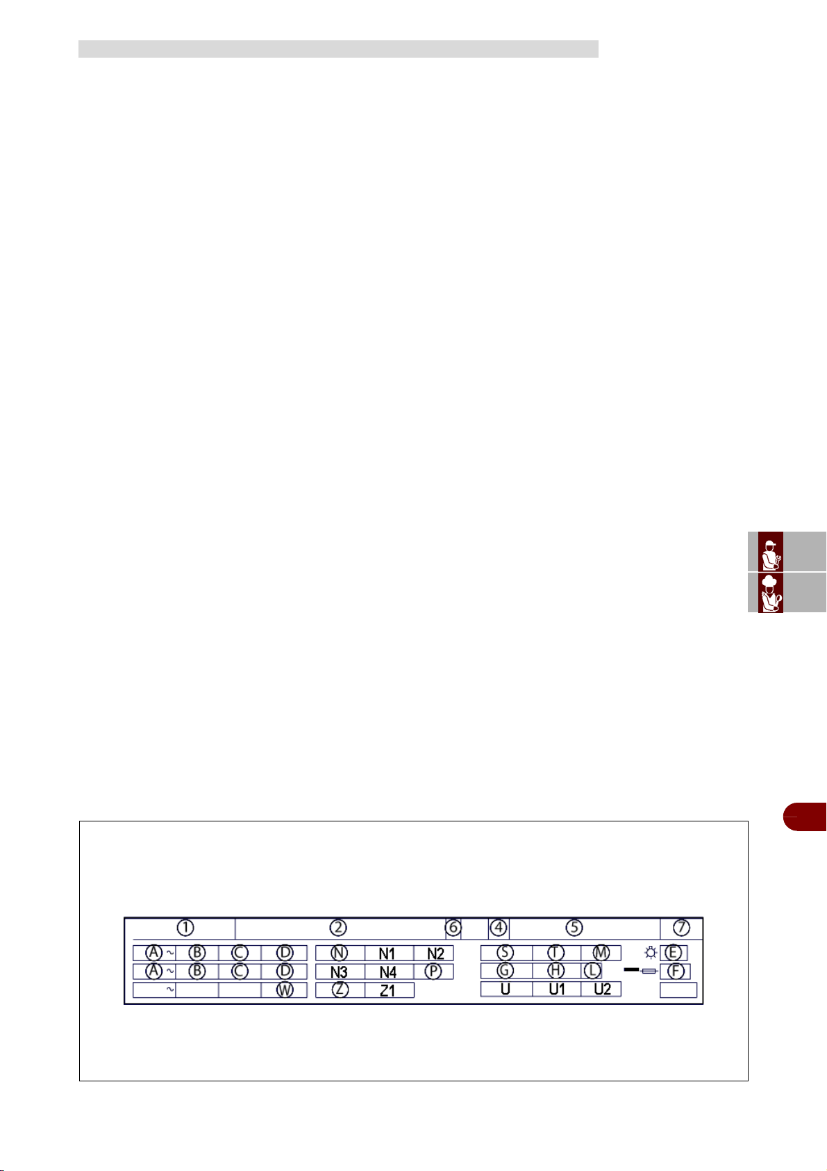
ES
CAN
DE
US
IT
3299702_rev.2.fIDM
Français
-
3
-
Manuel d’utilisation et d’installation
Vérifier que les données indiquées sur la plaque signalétique (sur le côté droit de la
cellule) correspondent aux caractéristiques techniques de la ligne électrique (V, kW,
Hz, n° des phases et puissance du réseau).
Pour toute communication avec le constructeur, donner le numéro de série de l'appa-
reil indiqué sur la plaque des caractéristiques techniques.
La plaque d’identification représentée, est appliquée directement sur l'appareil. Elle
reporte les références et les indications indispensables à la sécurité.
1–Modèle
2–Constructeur et ses coordonnées
4–Année de construction
5–N° de série
6–Classe èlectrique
7–Degré de protection des enveloppes des dispositifs électriques
A–Tension d'alimentation électrique
B–Intensité de courant électrique
C–Fréquence
D–Phase
E–Puissance totale lampes
F–Fisible
G–Type de fluide réfrigérant
H–Quantité de fluide réfrigérant
L–Classe di température
M–Pression max alimentation eau
N–Compresseur
N1–Compresseur RLA
N2–Compresseur LRA
N3–Ventilateur du condenseur
N4–Ventilateur du condenseur FLA
P–Fluide expansion
S–Chauffage du dégivrage
T–Puissance dégivrage chauffe
U–Valeur de pression
U1–Pression côté haut
U2–Pression côté basse
W–MCA
Z–Ventilateur de l'évaporateur
Z1–Ventilateur de l'évaporateur FLA
IDENTIFICATION DU FABRICANT ET DE L’APPAREIL
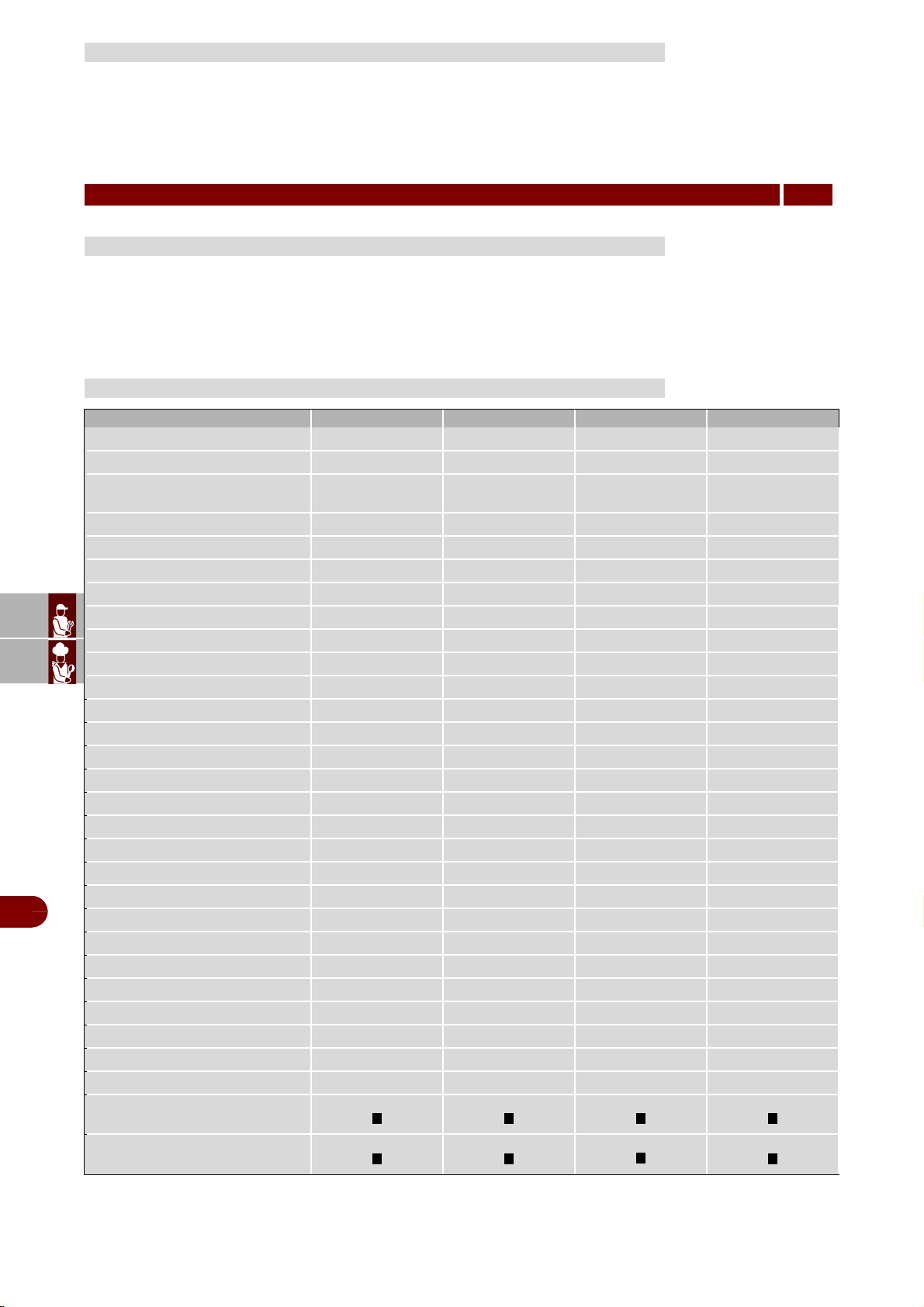
ES
CAN
DE
US
IT
3299702_rev.2.fIDM
Français
-
4
-
Manuel d’utilisation et d’installation
Pour toute exigence, s’adresser à l’un des centres autorisés.
Pour toute demande d’assistance technique, indiquer les données reportées sur la
plaque d’identification et le type de défaut relevé.
L'abatteur de température est une machine réfrigérante capable de refroidir la tempé-
rature d'un produit à peine cuit jusqu'à 135°F (57°C) et jusqu'à 40°F (4°C), pour le con-
server sur une longue période sans en altérer les caractéristiques organoleptiques.
La quantité de denrèes à réfrigérer et/ou à congeler dépend du modèle que l'on a acheté.
DEMANDE D'ASSISTANCE
INFORMATIONS TECHNIQUES
2
DESCRIPTION GÉNÉRALE DE L'APPAREIL
DONNÉES TECHNIQUES
Description B151HU B151MU B152MU B1101SU
Poids brut (lb)
309 309 342 507
Poids net (lb)
276 276 320 452
Dimensions
36.57"x30.67"x
33.07"
29.38"x28.38"x
38.19"
34.29"x35.51"x
37.28"
31.49"x32.68"x
73.23"
Capacité
Masse/cycle [lb] (+194°F ÷ +37°F)
48 35 55 100
Masse/cycle [lb] (+194°F ÷ +0°F)
22 28 33 60
Volume net intérieur [cuft]
2.55 2.55 3.5 5.52
Grades
3 3 3 3
Electricité
Tension [V]
220 ~ 220 ~ 220 ~ 220 ~
Fréquence [Hz]
60 60 60 60
N° Phase
1 ph 1 ph 1 ph 3 ph
Intensité [A]
6 6 6,13 8.5
Puissance absorbé [W]
1122 1139 1520 2625
Groupe réfrigérant
Puissance réfrigérante [W]
1054 1054 1319 2604
Température d’évaporation [°F]
-22 -22 -22 -22
Température de réfrigération [°F]
+194 ÷ +37 +194 ÷ +37 +194 ÷ +37 +194 ÷ +37
Temps de réfrigération [min]
90 90 90 90
Température de congélation [°F]
+194 ÷ 0 +194 ÷ 0 +194 ÷ 0 +194 ÷ 0
Temps de congélation [min]
240 240 240 240
Température de condensation [°F]
+130 +130 +130 +130
Température max ambiante [°
F
]
+90 +90 +90 +90
Type de compresseur
Hermétique Hermétique Hermétique Hermétique
Liquide réfrigérant
R404A R404A R404A R404A
Charge liquide réfrigérant [lb]
3 3 3.3 4.4
Condensation
Air Air Air Air
Bruit [dB] (A)
65 65 65 72
IFR
Sonde a relevement multiple

ES
CAN
DE
US
IT
3299702_rev.2.fIDM
Français
-
5
-
Manuel d’utilisation et d’installation
Même si l’appareil est complet de tous les dispositifs de sécurité, lors de l’installation
et du raccordement, ils devront, si nécessaire, être intégrés avec d’autres pour re-
specter les lois en vigueur.
Attention
Vérifier quotidiennement que les dispositifs de sécurité soient parfaitement in-
stallés et efficaces.
Sur demande l'appareil peut être équipé des accessoires suivants "vea el catálogo-
general".
–Le fabricant, lors de la conception et de la fabrication, a fait très attention aux aspects
qui peuvent provoquer des risques à la sécurité et à la santé des personnes qui inter-
agissent avec l’appareil. Non seulement il a respecté les lois en vigueur à ce sujet,
mais il a adopté toutes les «règles de la bonne technique de fabrication». Le but de
ces informations est de sensibiliser les utilisateurs à faire très attention pour prévenir
tout risque. Mais la prudence est irremplaçable. La sécurité est aussi dans les mains
de tous les opérateurs qui interagissent avec l’appareil.
–Lire attentivement les instructions reportées dans le manuel fourni et celles appli-
quées directement sur l'appareil, en particulier respecter celles concernant la sécurité.
–Ne pas heurter ou faire tomber l'appareil au cours des opérations de transport, ma-
nutention et installation, pour éviter d’endommager ses composants.
–Ne pas modifier, ne pas éluder, ne pas éliminer ou by-passer les dispositifs de sé-
curité installés. Le non-respect de cette condition peut entraîner des risques graves
pour la sécurité et la santé des personnes.
–Même après s'être documenté opportunément, à la première utilisation, si néces-
saire, simuler quelques manoeuvres d'essai pour localiser les commandes, en par-
ticulier celles relatives à l'allumage et à l'extinction, et leurs fonctions principales.
–Utiliser l’appareil uniquement pour les usages prévus par le fabricant. L’utilisation de
l’appareil pour des usages impropres peut entraîner des risques pour la sécurité et la
santé des personnes ainsi que des dommages économiques.
–Tous les entretiens qui demandent une compétence technique précise ou des ca-
pacités particulières ne peuvent être exécutés que par du personnel qualifié, ayant
une expérience reconnue et acquise dans le secteur spécifique d’intervention.
–Nettoyer soigneusement toutes les pièces qui peuvent être en contact direct ou in-
direct avec les aliments et toutes les zones avoisinantes, pour maintenir l’hygiène et
protéger les aliments de toute contamination.
–Effectuer le nettoyage exclusivement avec des produits détergents pour usage ali-
mentaire. Il est absolument interdit d’utiliser des produits de nettoyage corrosifs, in-
flammables ou qui contiennent des substances nocives à la santé des personnes.
–Effectuer le nettoyage lorsque cela s’avère nécessaire et, de toute façon, après
DISPOSITIFS DE SÉCURITÉ
ACCESSOIRES SUR DEMANDE
SÉCURITÉ
3
AVERTISSEMENTS GÉNÉRAUX DE SÉCURITÉ

ES
CAN
DE
US
IT
3299702_rev.2.fIDM
Français
-
6
-
Manuel d’utilisation et d’installation
chaque utilisation de l'appareil.
–Porter les équipements de protection individuels (gants, masques, lunettes, etc.),
comme prévu par les lois en vigueur en matière de sécurité et de santé, à chaque dés-
infection et nettoyage de l'appareil avec des produits détergents.
–En cas d’inactivité prolongée, nettoyer soigneusement l’intérieur et l’extérieur de
l'appareil et tout ce qui l’entoure (comme indiqué par le fabricant) et débrancher toutes
les lignes d’alimentation.
–Un opérateur doit être constamment présent pendant l’utilisation quotidienne de l’ap-
pareil.
–Ne pas diriger de jets d’eau sous pression sur l’extérieur et l’intérieur de l'appareil,
pour ne pas endommager les composants, enparticulier ceux électriques et électron-
iques .
–Ne pas laisser d’objets ou de matières inflammables près de l'appareil.
Important
Les installations ou les réparations effectuées par des personnes non autor-
isées ou avec des pièces de rechange non originales, ainsi que toute modifica-
tion technique non approuvée par le fabricant conduisent à l'extinction de la
garantie et de la responsabilité pour les dommages au produit de la part du fab-
ricant.
–L'équipement électrique a été conçu et construit conformément aux normes en
vigueur en la matière. Ces normes tiennent en considération les conditions de fonc-
tionnement selon le milieu environnant.
–La liste reporte les conditions nécessaires pour le fonctionnement correct de
l’équipement électrique.
-La température ambiante ne doit pas être inférieure à 41°F.
-L'humidité relative doit être comprise entre 50% (relevée à 104°F) et 90% (relevée
à 68°F).
-Le lieu d’installation ne doit pas être une source de perturbations électromagné-
tiques et de radiations (rayons X, laser, etc.).
-Les produits et les matériels utilisés pendant le travail et les opérations d’entretien
ne doivent pas contenir d’agents contaminants et corrosifs (acides, substances
chimiques, sels, etc.) et ne doivent pas pouvoir pénétrer dans les composants élec-
triques et/ou entrer en contact avec eux.
-Au cours du transport et du stockage, la température du milieu ambiant doit être
comprise entre -13°F et 131°F. L'équipement électrique peut être exposé à une
température jusqu’à 158°F, à condition que le temps d’exposition ne soit pas
supérieur à 24 heures.
S’il n’est pas possible de respecter une ou plusieurs des conditions parmi celles
énumérées, indispensables pour le fonctionnement correct de l’équipement élec-
trique, il faut fixer au moment de l’établissement du contrat les solutions supplémen-
taires qui pourraient être adoptées pour créer les conditions les plus appropriées (par
exemple, composants électriques spécifiques, appareils de conditionnement, etc.).
AVERTISSEMENTS DE SÉCURITÉ POUR L’ÉQUIPEMENT ÉLECTRIQUE

ES
CAN
DE
US
IT
3299702_rev.2.fIDM
Français
-
7
-
Manuel d’utilisation et d’installation
45 kg
–Chaque organisation a pour but d’appliquer des procédures pour trouver et contrôler
l'influence des propres activités (produits, services, etc.) sur l’environnement.
–Les procédures pour évaluer les impacts significatifs sur l’environnement doivent te-
nir compte des facteurs suivants.
-Émissions dans l'atmosphère
-Évacuations des liquides
-Gestion des déchets
-Contamination du sol
-Utilisation des matières premières et des ressources naturelles
-Problèmes locaux relatifs à l'impact environnemental
Pour cela le fabricant fournit quelques indications qui devront être considérées par
tous ceux autorisés à interagir avec l'appareil au cours de sa vie prévue, pour prévenir
l'impact environnemental.
–Tous les éléments de l’emballage doivent être éliminés conformément aux lois en
vigueur dans le pays d’utilisation.
–Lors de l’utilisation et de l’entretien, éviter de déverser dans l’atmosphère des pro-
duits polluants (huiles, graisses, etc.) et effectuer la collecte différenciée des déchets
en fonction de la composition des différentes pièces et en respectant les lois en-
vigueur en la matière.
–Si l’on veut supprimer l’appareil, sélectionner tous les composants en fonction de-
leurs caractéristiques et effectuer la collecte différenciée.
Important
Ne pas évacuer les matières polluantes dans l’atmosphère. Effectuer l’élimina-
tion dans le respect des lois en vigueur en la matière.
Important
L’évacuation abusive des déchets d’équipements électriques et électroniques
est passible de sanctions conformément aux lois en vigueur dans le territoire
où l’infraction a été commise.
Les déchets des équipements électriques et électroniques peuvent contenir
des substances dangereuses avec des effets potentiellement nocifs sur l'envi-
ronnement et sur la santé des personnes. L'évacuation et l'élimination doivent
être faites de façon correcte.
Cette unité est capable de réduire la température interne du contenu à partir de 135°F
(57°C) à 40°F (4°C) dans les 4 heures, pour le conserver sur une longue période sans
en altérer les caractéristiques organoleptiques.
La quantité de denrèes à réfrigérer et/ou à congeler dépend du modèle que l'on a
acheté.
Important
– L'incidence des accidents qui dérivent de l’utilisation des appareils dépend de
nombreux facteurs qu’il n’est pas toujours possible de prévoir et de contrôler.
Certains accidents peuvent dépendre de facteurs environnementaux imprévisi-
bles, d’autres dépendent surtout des comportements des utilisateurs.
AVERTISSEMENTS DE SÉCURITÉ POUR L’IMPACT ENVIRONNEMENTAL
UTILISATION ET FONCTIONNEMENT
4
RECOMMANDATIONS POUR L'UTILISATION

ES
CAN
DE
US
IT
3299702_rev.2.fIDM
Français
-
8
-
Manuel d’utilisation et d’installation
En plus d'être autorisés et formés comme il se doit, ces derniers devront si né-
cessaire, comme entraînement à l'utilisation, simuler certaines manœuvres
pour identifier les commandes et les fonctions principales.
–N’utiliser l’appareil que pour les buts pour lesquels il a été conçu et ne modi-
fier aucun dispositif pour obtenir des performances différentes de celles pré-
vues.
–Avant chaque utilisation, vérifier que les dispositifs de sécurité soient par-
faitement installés et efficaces.
–Les utilisateurs doivent s’engager à satisfaire les conditions requises, appli-
quer toutes les normes de sécurité et lire attentivement la description des com-
mandes et la mise en service.
–Signaler au plus tôt toute anomalie ou détérioration des composants ou des
parties de l'appareil, et faire intervenir si nécessaire un personnel qualifié pour
les activités de contrôle et de remplacement.
Avant toute utilisation, il faut nettoyer l’intérieur de la cellule d'une manière soignée,
avec une solution détergente apprpriée.
La durée de réfrigeration rapide et de congelation dépend des facteurs suivants:
a) forme, type et matériel des contenants utilisés;
b) utilisation de couvercles sur les contenants;
c) caractéristiques de l'aliment (densité, teneur en eau, teneur en graisses);
d) température en dèbut de cycle;
e) conduction thermique de l'aliment.
Le temps de réfrigération rapide positive et de réfrigération rapide négative est en
fonction du type de produit traité.
En général, les programmes de fonctionnement de la machine, se basent sur la ges-
tion de la température de la chambre, de la vitesse des ventilateurs et sur le temps de
refroidissement, et dans tous les cas, il ne faut pas excéder 7lb de charge (pour des
plats 12”x20”) ou 15lb de charge (pour les plats 18”x26”) et une épaisseur de 2” en
phase de réfrigération négative et de 3” en phase de réfrigération positive.
Vérifier que le programme de réfrigération positive, jusqu'à +37°F au coeur du produit,
ne prenne pas plus de 90 minutes et que le programme de réfrigération négative,
jusqu'à 0°F au coeur du produit, ne dépasse pas les 4 heures.
Il est conseillé de pré-refroidir la chambre de travail avant de commencer un pro-
gramme de réfrigération et de ne pas couvrir les aliments pendant le programme pour
ne pas augmenter le temps de refroidissement.
Quand l’épaisseur du produit le consent, utiliser toujours la sonde à coeur pour con-
naître la température exacte atteinte au coeur du produit, et ne pas interrompre le cy-
cle avant qu’on atteigne la température de +37°F en réfrigération rapide positive et
0°F en réfrigération rapide négative.
COMMENT SE PRÉPARER AU DÉMARRAGE
Modéle Rendu max/cycle Capacité h
+194°F ÷ +37°F +194°F ÷ 0°F n°max
B151HU 35 lb 22 lb 10 12”x20” 1.5”
B151MU 48 lb 28 lb 6 12”x20” 1.5”
B152MU 55 lb 33 lb 6 18”x26” 1.5”
B1101SU 100 lb 60 lb 12 12”x20” 1.5”
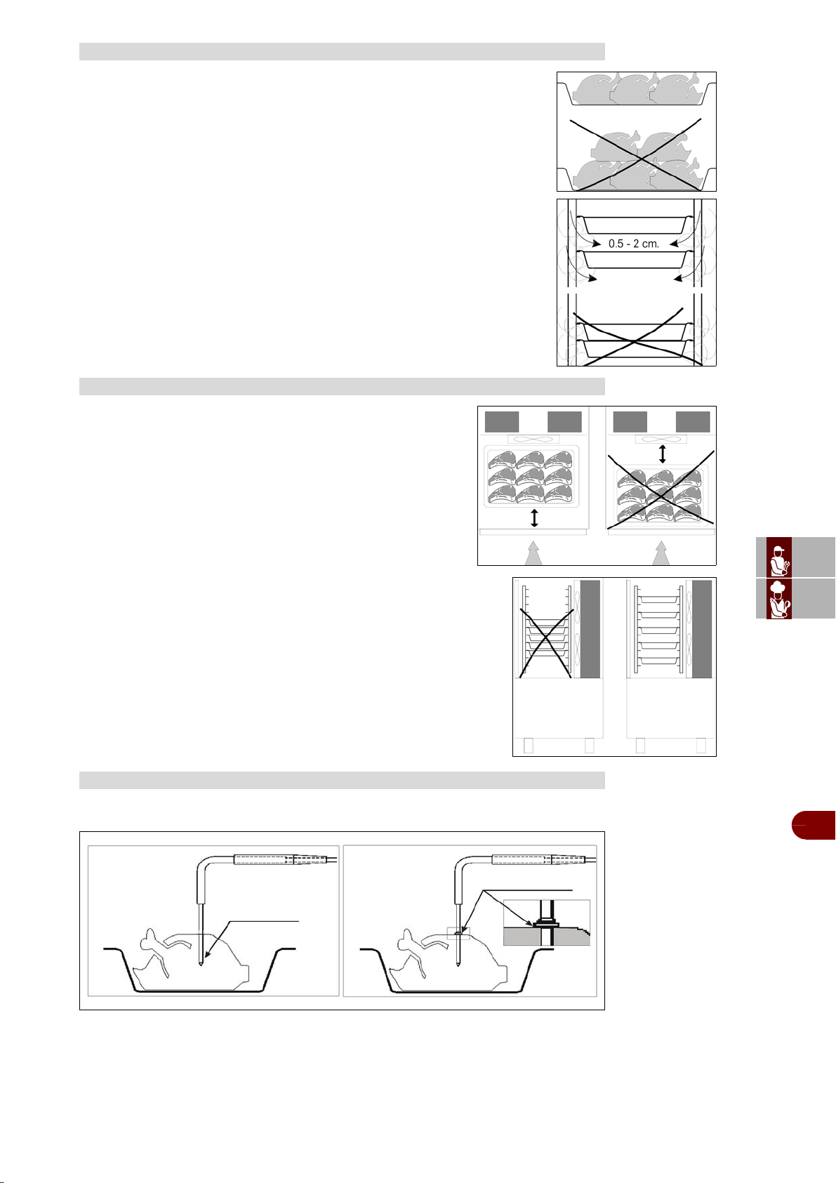
ES
CAN
DE
US
IT
3299702_rev.2.fIDM
Français
-
9
-
Manuel d’utilisation et d’installation
Faire attention à ce que les produits à réfrigérer rapidement ne soient pas
superposés.
Les épaisseurs doivent être inférieures à 2” en réfrigération rapide négative
et 3” en réfrigération rapide positive.
S'assurer que l'air circule suffisamment entre les contenants.
Il faut placer les contenants près de l'évaporateur.
Si l'appareil n'est pas totalememt rempli, il faut placer les contenants
à une distance égale les uns de l'autre.
Pour garantir un bon fonctionnement de la sonde se référer aux figures suivantes.
CHARGEMENT DE LA CELLULE
PLACEMENT DES RÉCIPIENTS
SONDE A COEUR
COEUR PRODUIT
SUPERFICIE PRODUIT
SONDE A RELEVE-
MENT MULTIPLE
SONDE A RELEVE-
MENT UNIQUE
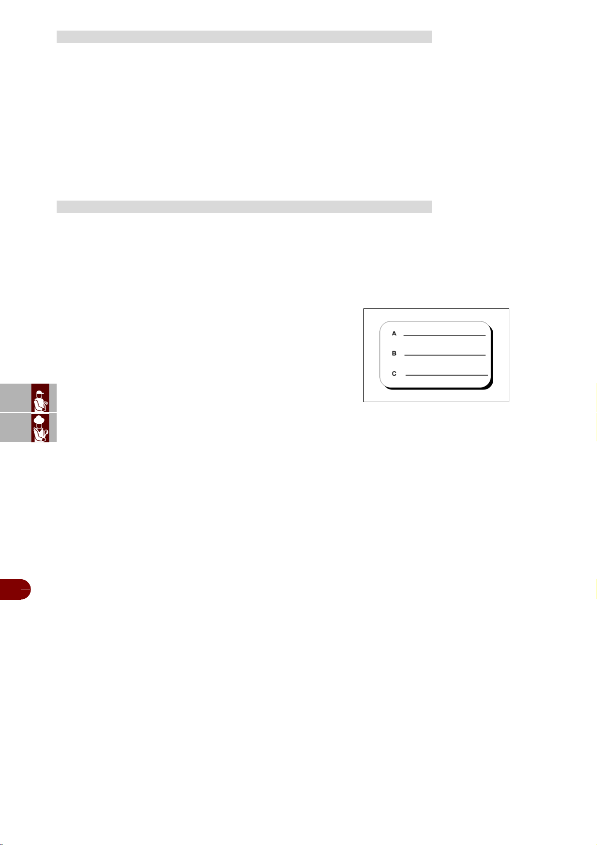
ES
CAN
DE
US
IT
3299702_rev.2.fIDM
Français
-
10
-
Manuel d’utilisation et d’installation
Ne pas laisser à température ambiante les produits cuits et à abattre/congeler.
Éviter la perte d'humidité, sous peine de perdre la fragrance conservée du produit.
Il est conseillé de commencer le programme de réfrigération/congélation juste après
avoir terminé la phase de préparation ou de cuisson, en prenant soin d'insérer le pro-
duit dans l'appareil à une température d'au moins +160°F. Le produit cuit peut entrer
dans l'appareil même avec une température très élevée, supérieure à +212°F, du mo-
ment que la chambre ait été pré-refroidie.
Il faut toujours garder à l'esprit que les temps de référence des programmes partent
toujours à partir de la température de +194°F, en réfrigération positive, de +194°F à
+37°F, et en réfrigération négative de +194°F à 4°F.
Un produit cuit et ensuite refrigeré ou congélé peut être conservé dans le réfrigérateur
sans perdre ses proprietés essentielles jusqu'à 5 jours après le traitement.
Il est très important de respecter la chaîne du froid, c'est à dire, de maintenir pendant
la conservation une température constante entre 32°F et 0°F, selon le type d'aliment
traité.
Le temps de conservation peut être prolongé jusqu'à 15 jours environ, par la technique
du traitement sous vide.
Les produits qui ont subi un cycle d réfrigération rapide négative
peuvent être conservés avec sécurité pendant une durée comprise
entre 3 et 18 mois et ce d’après l’aliment traité.
On conseille de respecter une température de conservation égale
ou inférieure à –4°F.
Le produit réfrigéré doit être protégé par une pellicule pour aliments
(mieux encore, sous vide) et muni d'une etiquette adhésive sur
laquelle on a écrit la description du contenu [A], le jour de prépara-
tion [B] et la date d'écheance prévue [C], en caractères ineffaçables.
TEMPÉRATURES
DURÉE DE CONSERVATION
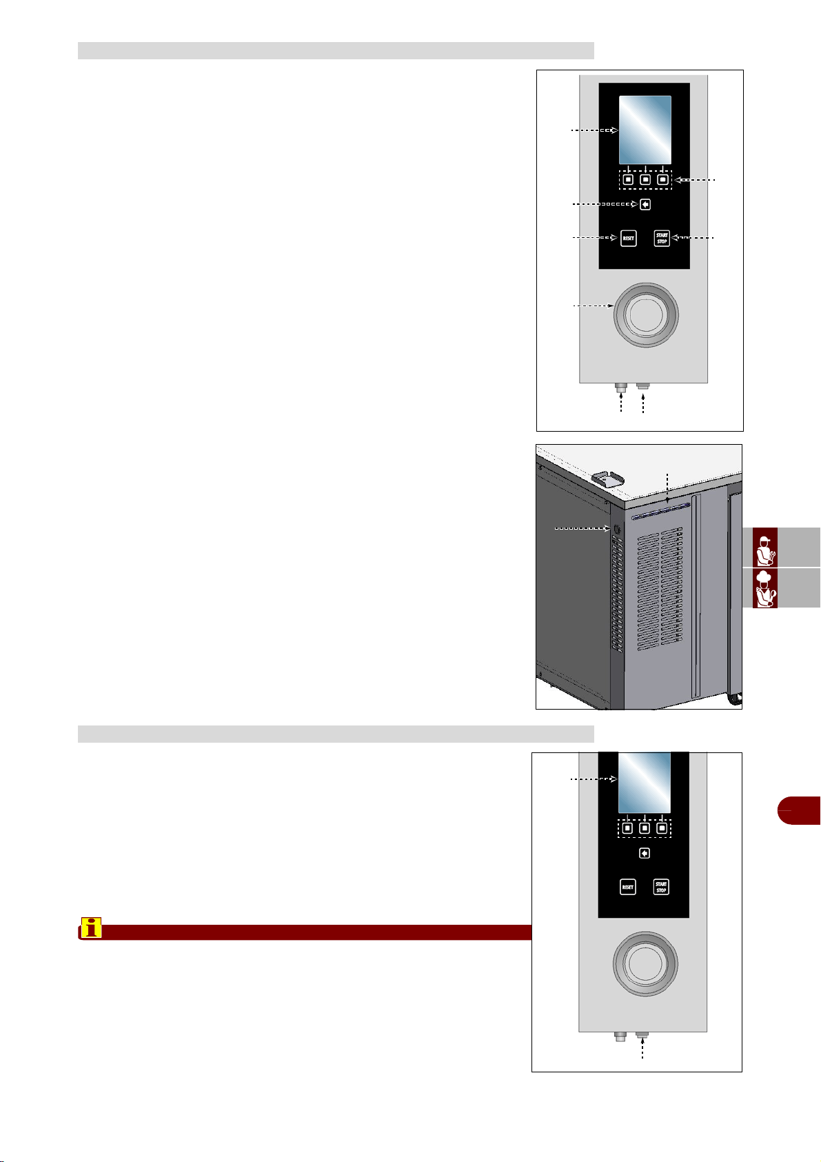
ES
CAN
DE
US
IT
3299702_rev.2.fIDM
Français
-
11
-
Manuel d’utilisation et d’installation
La figure ci-contre représente le tableau de commandes de l'appareil,tandis
que la liste reporte la description et la fonction de chaque com-mande.
A–
Afficheur numérique
: il affiche les paramètres de travail et les si-
glesdes alarmes.
B–Touche d’activation des fonctions: elle sert pour activer la fonction-
affichée sur l’afficheur.
C–Touche en arrière: elle sert pour annuler l’opération en cours et re-
tourner à la page précédente.
D–
Touche reset
: elle sert pour remettre à zéro les signaux d’alarme
(acoustiques et visuels).
E–Touche “START-STOP”: elle sert pour commencer ou terminer
lecycle du programme sélectionné et affiché sur l’afficheur.
F–
Manette
: elle sert pour sélectionner la fonction choisie ou modifierles valeurs.
Pour sélectionner une des zones (fonction ou valeur), tourner la manet-
teen sens horaire ou anti-horaire.
-Sens horaire: on fait défiler les zones «vers le bas» ou on augmentela
valeur mise en évidence.
-Sens anti-horaire: on fait défiler les zones «vers le haut» ou on di-
minue la valeur mise en évidence.
À chaque fois que l’on sélectionne la fonction choisie ou la valeur, appuy-
er sur la manette pour confirmer et enregistrer la fonction ou la valeur.
G–Bouton d’allumage: il sert pour activer et désactiver électrique-
mentl'appareil.
H–Port USB: il sert pour connecter une unité de mémoire à l’appareil.
L–Touche d'urgence "cellule": elle sert en cas d'anomalie de la carte
du four pour activer un cycle de refroidissement Soft +37°F.
M–La barre LED RGB, change de couleur en fonction du processus en
cours:
-Stand-by: lumière fixe bleue de faible intensité
-Cycle de réfrigération/congélation (inclus Infinity, Multy) décongéla-
tion et refroidissement, en cours: lumière intermittente bleue de forte
intensité
-Conservation en cours: lumière fixe bleue de forte intensité
-Décongélation en cours: lumière fixe rouge de faible intensité
-Sterilisation en cours: lumière fixe rouge de faible intensité
-Anomalie: lumière fixe jaune
Procéder comme suit.
Allumage
1–Agir sur l'interrupteur sectionneur de l'appareil pour activer le
branchement à la ligne électrique principale.
2–Presser la touche (G) pour activer l'appareil.
3–L’afficheur (A) s’allume et, au bout de quelques secondes, visualise
la page d’accès aux fonctions principales de l'appareil.
Extinction
Important
Toujours éteindre l'appareil à la fin de son utilisation.
4–Appuyer sur la touche (G) pour désactiver l'appareil.
5–Agir sur l'interrupteur sectionneur de l’appareil pour désactiver le
branchement à la ligne électrique principale.
DESCRIPTION DES COMMANDES
ALLUMAGE ET EXTINCTION DE L’APPAREIL
A
C
D
F
B
E
G
H
L
M
A
G
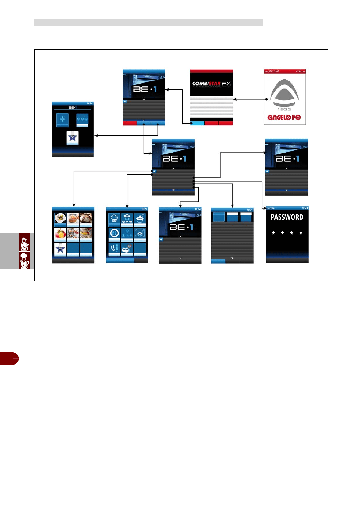
ES
CAN
DE
US
IT
3299702_rev.2.fIDM
Français
-
12
-
Manuel d’utilisation et d’installation
L'illustration représente l'organisation et la séquence des pages principales relative-
saux différents modes de fonctionnement.
A–Page de présentation: elle s’affiche à l’allumage de l’appareil.
B–Page fonctions principales (home page four): elle sert pour accéder aux pages
de pro-grammation et d’affichage des paramètres de fonctionnement de four.
C–Page fonctions principales (home page refrodisseur): elle sert pour accéder
aux pages de pro-grammation et d’affichage des paramètres de fonctionnement de re-
frodisseur (voir page 13) et pour sélectionner cycles de réfrigération/congélation
préréglés par le constructeur (voir page 16).
D–Page "menù": pour accéder au menu de la cellule de refroidissement.
E–Page "programmes automatiques": cycles de réfrigération/congélation conseil-
lés par le constructeur (voir page 20).
F–Page “fonctions spéciales”: Levain, décongeler, boîte de yaourt, parasites, con-
servation, degivrage, refroidissment, ifr (voir page 30).
G–Page "configurations": sert pour configurer les paramètres de fonctionnementde
l'appareillage (voir page 39).
H–Page “Service”: fonction exclusivement réservée au Service d'Assistance (à uti-
liser avec le Mot de passe).
L–Page “HACCP”: sert pour visualiser les données HACCP acquises pendant les
cycle.
M–Page "chargement/déchargement données": (Mémoire USB).
N–Page "programmes utilisateur": cycles de réfrigération/congélation qui peuvent
être réglés en fonction des exigences de l'utilisateur et dont le nom peut être réglé à
discrétion (voir page 25).
DESCRIPTION DU SCHÉMA LOGIQUE DU MENU
(D) Page “menù"
(N) Page
"programmes utilisateur"
(E) Page "programmes
automatiques"
(G) Page
"configurations"
(A) Page de
présentation
(B) Page fonctions princi-
pales (home page four)
(F) Page
"fonctions spéciales"
(H) Page
"Service”
(C) Page fonctions principales
(home page refrodisseur) /
“programmes standard"
(L) Page
"HACCP”
(M) Page "chargement/
déchargement données”
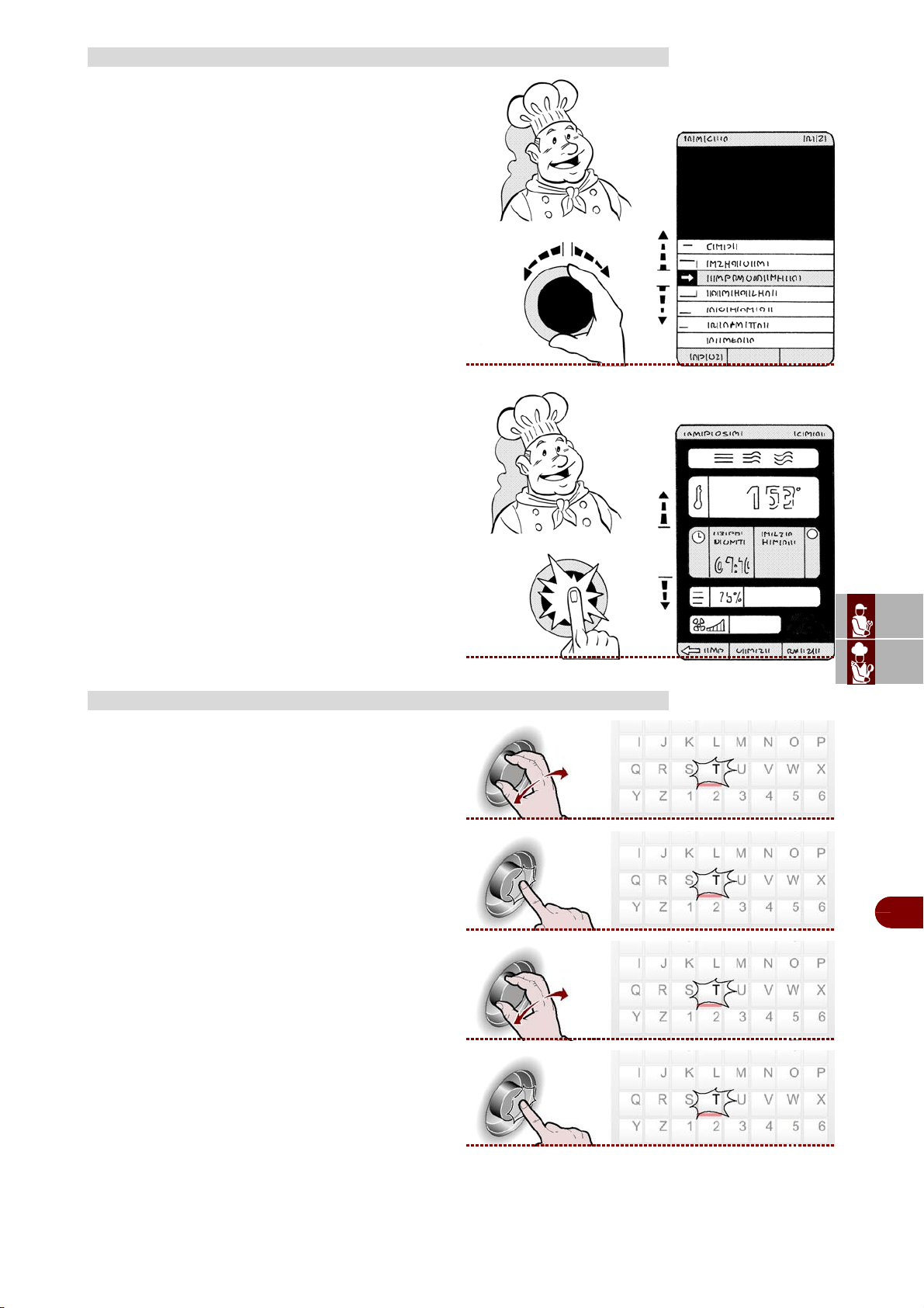
ES
CAN
DE
US
IT
3299702_rev.2.fIDM
Français
-
13
-
Manuel d’utilisation et d’installation
Procéder comme suit.
1–Sélectionner la fonction choisie (sous-menu)
avec la manette.
2–Appuyer sur la manette pour confirmer la fonction
mise en évidence.
3–Sélectionner le paramètre à modifier avec la
manette.
4–Appuyer sur la manette pour confirmer le para-
mètre mis en évidence.
5–Modifier la valeur du paramètre mis en évidence
avec la manette.
6–Appuyer sur la manette pour confirmer la nouv-
elle valeur affichée.
Procéder comme suit.
1–Mettre en évidence le premier caractère (lettre ou
numéro) choisi en tournant la manette. >>>
2–Appuyer sur la manette pour confirmer la sélec-
tion mise en évidence. >>>
3–Mettre en évidence le second caractère (lettre ou
numéro) choisi en tournant la manette. >>>
4–Appuyer sur la manette pour confirmer la sélec-
tion mise en évidence. >>>
5–Répéter l’opération jusqu’à obtenir la valeur ou la
description complète.
MODALITÉS D’ACCÈS AUX PAGES DES MENUS
MODALITÉS D’INTRODUCTION DES VALEURS ALPHANUMÉRIQUES
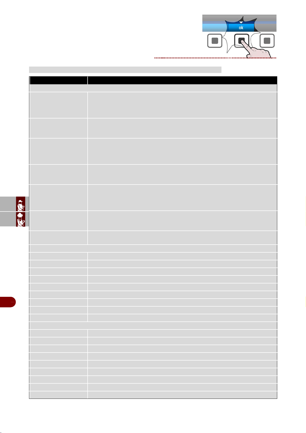
ES
CAN
DE
US
IT
3299702_rev.2.fIDM
Français
-
14
-
Manuel d’utilisation et d’installation
6–Presser la touche pour confirmer la valeur ou la
description mise en évidence. >>>
DESCRIPTION DES PROGRAMMES
PROGRAMME DESCRIPTION
PROGRAMMES STRANDARDS
SOFT +
Cycle réalisé à l'aide d'une sonde au cœur ou à temps, idéal pour refroidir des ali-
ments jusqu'à +37°F, en utilisant une température de chambre autour de 0°F.
Cycle indiqué pour des produits délicats tels que mousses, crèmes, desserts,
légumes ou aliments ayant une épaisseur réduite
HARD +
Cycle réalisé à l'aide d'une sonde au cœur ou à temps, idéal pour refroidir des aliments
jusqu'à +37°C, en utilisant une température de chambre pouvant varier de 5°F à 34°F.
Cycle indiqué pour des produits très denses, à fort contenu en graisse ou de grand format
SOFT -
Cycle réalisé à l'aide d'une sonde au cœur ou à temps, idéal pour congeler des aliments
jusqu'à 0°F, en utilisant une température de chambre pouvant varier de 34°F à -40°F.
Cycle indiqué pour des produits au levain, pour four ou des aliments cuits d'une épais-
seur réduite
HARD -
Cycle réalisé à l'aide d'une sonde au cœur ou à temps, idéal pour congeler des ali-
ments jusqu'à 0°F, en utilisant une température de chambre qui peut atteindre -40°F.
Cycle indiqué pour des produits crus ou cuits de grand format
IFR-ECO
I.F.R. est le système breveté de réfrigération positive qui optimise automatiquement
le processus quelle que soit la typologie d'aliment, indépendamment du format et de
la quantité, prévenant sa congélation superficielle, grâce à l'utilisation d'une sonde
à piquer multipoint à trois capteurs
MULTY - INFINITY
Cycle de réfrigération / congélation à temps dont la durée est infinie, idéal pour re-
froidir des plats d'aliments de typologie différente. Il est possible de contrôler la tem-
pérature au cœur
DEGIVRAGE
Cycle de nettoyage de la glace de la batterie évaporante, présente en surface afin
d'optimiser le fonctionnement de la cellule de refroidissement.
PROGRAMMES AUTOMATIQUES +37°F - RESTAURATION
LASAGNE Cycle pour la réfrigération de lasagne
SOUPES ET SAUCES Cycle pour la réfrigération de soupes et de sauces
RIZ ET PATE Cycle pour la réfrigération de riz et de pâtes
VIANDE Cycle pour la réfrigération de viande
POISSON Cycle pour la réfrigération de poisson
LEGUMES CRUITS Cycle pour la réfrigération de légumes cuits
PATISSERIE CHAUDE Cycle pour la réfrigération de produits de pâtisserie chaude
PATISSERIE SECHER Cycle pour la réfrigération de produits de pâtisserie sèche
VEAU NOIX Cycle pour la réfrigération de produits de veau noix
PROGRAMMES AUTOMATIQUES 0°F - RESTAURATION
LASAGNE Cycle pour la congélation de lasagne
SOUPES ET SAUCES Cycle pour la congélation de soupes et de sauces
RIZ ET PATE Cycle pour la congélation de riz et de pâtes
VIANDE Cycle pour la congélation de viande
POISSON Cycle pour la congélation de poisson
LEGUMES CRUITS Cycle pour la congélation de légumes cuits
LEGUMES CRUS Cycle pour la congélation de légumes crus
PATISSERIE Cycle pour la congélation de produits de pâtisserie
POISSON CRU Cycle pour la congélation de poisson cru

ES
CAN
DE
US
IT
3299702_rev.2.fIDM
Français
-
15
-
Manuel d’utilisation et d’installation
SUSHI Cycle pour la congélation de Sushi
ANISAKIS 24h*
Cycle de surgélation qui permet l'assainissement préventif et complet du produit à
base de poisson. La sonde relève la limite de la température au cœur de l'aliment
de -4°F donnant le déclic à la machine de faire partir la phase de “dévitalisation pen-
dant 24 heures”
ANISAKIS 15h*
Cycle de surgélation qui permet l'assainissement préventif et complet du produit à
base de poisson. La sonde relève la limite de la température au cœur de l'aliment
de -31°F donnant le déclic à la machine de faire partir la phase de “dévitalisation
pendant 15 heures”
OPISTORKIS 24h
Cycle de surgélation qui permet l'assainissement préventif et complet du produit à
base de poisson. La sonde relève la limite de la température au cœur de l'aliment
de -4°F donnant le déclic à la machine de faire partir la phase de “dévitalisation pen-
dant 24 heures”
PROGRAMMES AUTOMATIQUES +37°F - PÂTISSERIE
PETRISSAGE IN FEUILLES
Cycle pour la réfrigération de riz et de pâte en feuille
PETRISSAGE IN MOULE
Cycle pour la réfrigération de pâtes moulées
CREMES Cycle pour la réfrigération de crèmes
LEVES Cycle pour la réfrigération de produits au levain
LEVES +50°F Cycle pour la réfrigération de produits au levain +50°F
PATE BRISEE Cycle pour la réfrigération de pâte brisée
PRODUIT REMPLIS Cycle pour la réfrigération de produits fourrés
TARTES Cycle pour la réfrigération de tartes
BRIOCHE Cycle pour la réfrigération de brioche
CREME SURPLUS Cycle pour la réfrigération de creme surplus
YOGURT BOX Cycle pour la préparation de yogurt
PROGRAMMES AUTOMATIQUES 0°F - PÂTISSERIE
PETRISSAGE IN FEUILLES
Cycle pour la congélation de pâtes en feuille
PETRISSAGE IN MOULE
Cycle pour la congélation de pâtes moulées
TARTES Cycle pour la congélation de tartes
MOUSSE Cycle pour la congélation de mousses
CROISSANT Cycle pour la congélation de croissants
GLACE Cycle pour la congélation de glaces
PROGRAMMES AUTOMATIQUES +37°F - BOULANGERIE
TARTES Cycle pour la réfrigération de tartes
PAIN CUIT Cycle pour la réfrigération de pain cuit
CREMES Cycle pour la réfrigération de crèmes
LEVES Cycle pour la réfrigération de produits au levain
PROGRAMMES AUTOMATIQUES 0°F - BOULANGERIE
TARTES CUISSONS Cycle pour la congélation de tartes cuites
TARTES CRUES Cycle pour la congélation de tartes crues
PAIN CUIT Cycle pour la congélation de pain cuit
PAIN CRU Cycle pour la congélation de pain cru
PROGRAMMES AUTOMATIQUES +37°F - GLACIER
CREME SURPLUS Cycle pour la réfrigération de creme surplus
YOGURT BOX Cycle pour la préparation de yogurt
PROGRAMMES AUTOMATIQUES 0°F - GLACIER
GLACE -7°F Cycle pour la congélation de glaces -7°F
GLACE Cycle pour la congélation de glaces
MOUSSES COMPLETES
Cycle pour la congélation de mousses complètes
MOUSSE Cycle pour la congélation de mousses
PROGRAMME DESCRIPTION
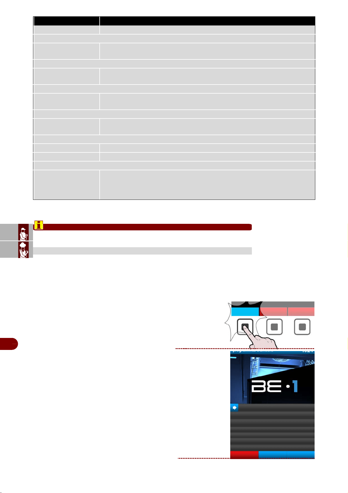
ES
CAN
DE
US
IT
3299702_rev.2.fIDM
Français
-
16
-
Manuel d’utilisation et d’installation
* Testés et validés en collaboration avec: L'Université Federico II de Naples - Département de Sciences
Zootechniques et Inspection Aliments Section Inspection Aliments et Laboratoire de Recherche Universi-
taire pour le marché du poisson en gros de Pozzuoli.
Important
Ne pas éteindre le four quand la cellule de refroidissement rapide est en marche.
Cycles de réfrigération/congélation préréglés par le constructeur, SOFT +, HARD +,
SOFT -, HARD -, IFR-ECO, MULTY - INFINITY, DÉGIVRAGE.
Pendant l'exécution du cycle, il est possible de visualiser les paramètres et de les
modifier de manière temporaire, les nouvelles valeurs auront validité exclusivement
pour le cycle en cours.
Procéder comme suit.
1– Depuis la page principale (home page four),
presser la touche pour entrer des modalité de refro-
disseur. >>>
2–Sur l’afficheur apparaît la page
(home page refrodisseur). >>>
SEMIFREDDO Cycle pour la congélation de semifreddo
PROGRAMME MULTY
MULTY
Cycle de réfrigération / congélation à temps, organisé par niveaux de charge, avec la
possibilité de lecture avec une sonde à piquer, laissant à chaque niveau son temps
PROGRAMME BANQUETING
BANQUETING
Cycle dédié au secteur de la restauration, idéal pour la préparation de produits de
banquet
PROGRAMME VACUUM
VACUUM
Cycle dédié au secteur de la restauration, pour la préparation de produits avant une
phase de sous-vide
PROGRAMME DÉCONGELER
DÉCONGELER
Cycle dédié à la décongélation contrôlée des aliments, réalisé par sonde à cœur ou
par temps
PROGRAMME LEVAIN
LEVAIN Cycle par temps, dédié au levage direct des aliments
LEVAIN CONTROLEE Cycle par temps, dédié au levage programmé des aliments
PROGRAMME SMART ON
SMART ON
Cycle avec démarrage automatique.
Une fois un produit chaud inséré, si une augmentation de température est relevée
dans la chambre, après 5 minutes, un cycle Soft 37°F démarre automatiquement, à
sonde ou à temps, en fonction de l'utilisation ou pas de la sonde à piquer.
PROGRAMMES STANDARD
PROGRAMME DESCRIPTION
refrodisseur
programmes standard
SOFT +
HARD +
SOFT -
HARD -
IFR - ECO
MULTY INFINITY
DÉGIVRAGE
four
menu
programmes
utilisateur
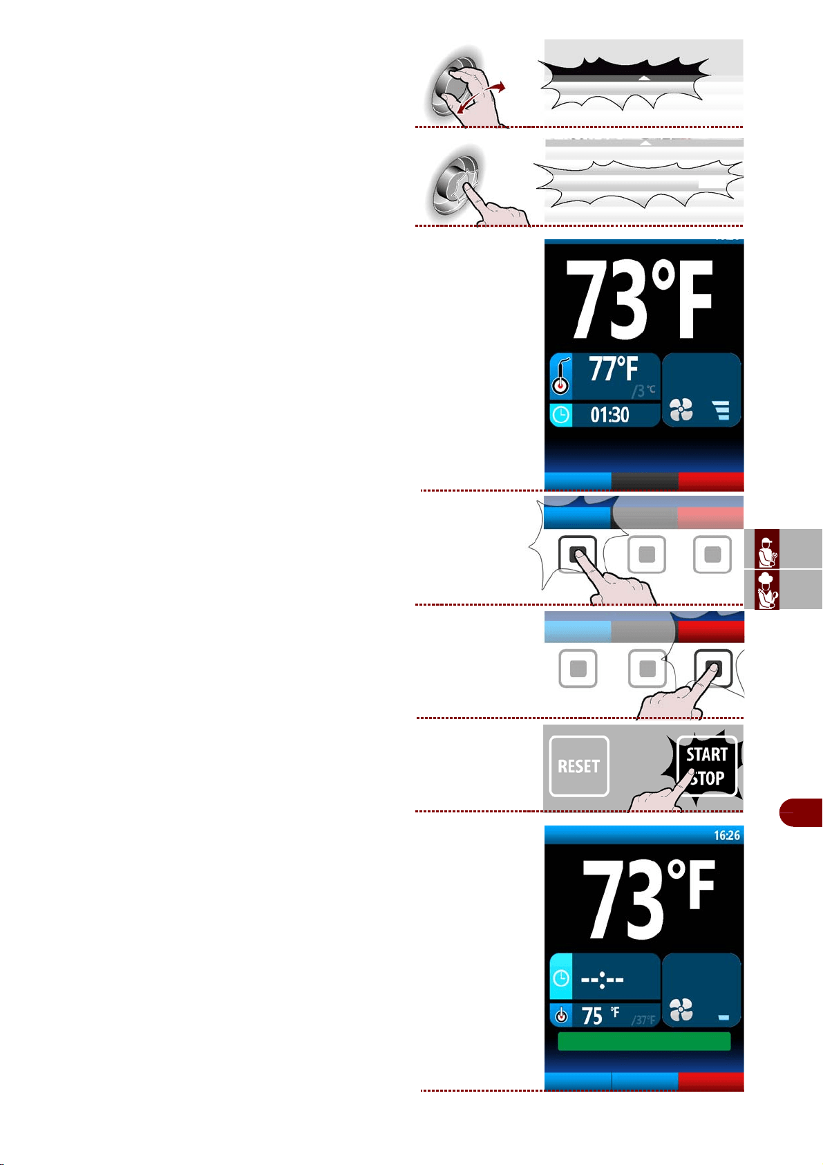
ES
CAN
DE
US
IT
3299702_rev.2.fIDM
Français
-
17
-
Manuel d’utilisation et d’installation
3–Sélectionner le cycle désiré en tournant la
manette.
>>
4–Appuyer sur la manette pour confirmer le choix
mis en évidence. >>>
Sur l’afficheur apparaît la page. >>>
Pendant le cycle, il est possible de:
-visualiser et de modifier les paramètres default
(voir page 19).
Remarque: les paramètres modifiés seront en-
registrés uniquement pour le cycle en cours.
-Sélectionner la fonction forno
.
-d'arrêter le cycle.
5–
Une fois le cycle terminé, une phase de conserva-
tion démarre automatiquement.
Sur l’afficheur apparaît la page. >>>
SOFT +
SOFT +
phase 1/2
four
Modifier les
paramètres
Modifier les
paramètres
four
phase 2/2
four
Modifier les
paramètres
defrost
CYCLE TERMINE: CONSERVATION EN COURS
SOFT +
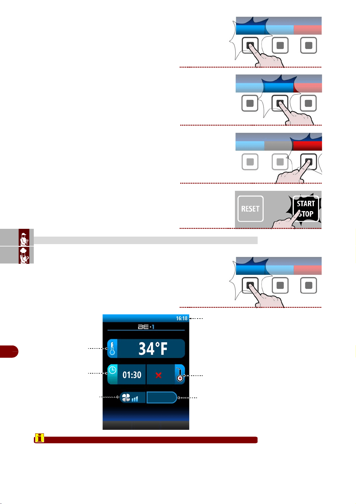
ES
CAN
DE
US
IT
3299702_rev.2.fIDM
Français
-
18
-
Manuel d’utilisation et d’installation
Pendant la conservation, il est possible de:
-visualiser et de modifier les paramètres default
(voir page 19).
Remarque: les paramètres modifiés seront en-
registrés uniquement pour le cycle en cours.
-activer le dégivrage manuel.
Si cela n'est pas nécessaire, le dégivrage
manuel n'est pas effectué.
-Sélectionner la fonction forno
.
-d'arrêter le cycle.
1–Pendant le cycle, sélectionner “Modifier les
paramètres”.
>>>
2–Sur l’afficheur apparaît la page.
Important
Le «temps de refroidissement» et la «température à cœur» sont deux fonctions
quis’excluent réciproquement. Si, par exemple, on sélectionne le «temps de re-
froidissement» puis la «température à cœur», la première fonction est annulée.
MODIFIER LES PARAMÈTRES
Modifier les
paramètres
defrost
four
Modifier les
paramètres
Température
chambre
Temps de
refroidissement
Température
“à cœur”
Vitesse du
ventilateur
Numéro phases
programme
Horaire
phase 1/2
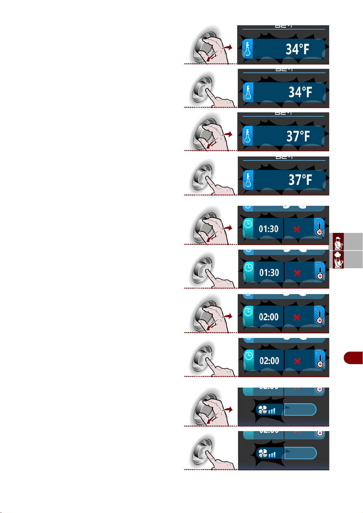
ES
CAN
DE
US
IT
3299702_rev.2.fIDM
Français
-
19
-
Manuel d’utilisation et d’installation
Température chambre
1–Sélectionner la zone "température chambre"
avec la manette.
>>
2–Appuyer sur la manette pour confirmer la zone-
mise en évidence. >>>
3–Pour modifier la température de cuisson, tourner-
la manette jusqu’à afficher la valeur choisie. >>>
4–ppuyer sur la manette pour confirmer la valeur-
mise en évidence. >>>
Temps de refroidissement ou Température à cœur
1–Sélectionner la zone, "emps de refroidissement"
ou "température à cœur" avec la manette.
>>
2–Appuyer sur la manette pour confirmer la zone-
mise en évidence. >>>
Si l’on sélectionne la fonction “temps de refroidisse-
ment” puis la “température à cœur”, la première fonc-
tionest annulée ou vice versa.
3–Pour modifier la valeur mise en évidence ("temps
de refroidissement" ou "température à cœur"), tourn-
er la manette jusqu’à ce que la valeur choisies’af-
fiche. >>>
4–Appuyer sur la manette pour confirmer la valeur-
mise en évidence. >>>
Vitesse du ventilateur
1–Sélectionner la zone «vitesse du ventilateur»avec
la manette.
>>
2–Appuyer sur la manette pour confirmer la zone-
mise en évidence. >>>
phase 1/2
phase 1/2
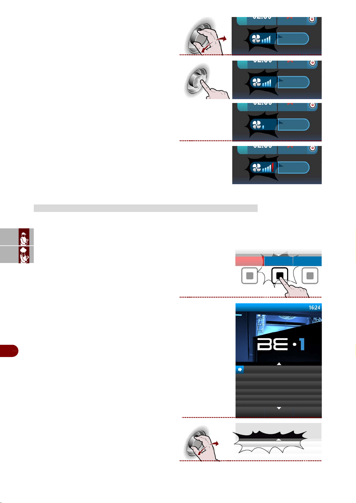
ES
CAN
DE
US
IT
3299702_rev.2.fIDM
Français
-
20
-
Manuel d’utilisation et d’installation
3–Pou modifier la vitesse du ventilateur de refroidis-
sement, tourner la manette pour augmenter ou di-
minuer le nombre de divisions de l’échelle graduée.
4–Appuyer sur la manette pour confirmer la valeur-
mise en évidence. >>>
5–Le symbole indique que le ventilateur de re-
froidisse-ment est programmé à la vitesse minimale.
6–ILe symbole indique que le ventilateur de re-
froidisse-ment est programmé à la vitesse maximale.
Ces programmes sont des cycles de travail conseillés par le constructeur.
Il est possible, pendant le cycle, de visualiser les paramètres, mais pas de les modifier.
Procéder comme suit.
1–Depuis la page principale (home page refrodis-
seur), presser la bouton pour entrer dans le menu.
>>>
Sur l’afficheur apparaît la page. >>>
2–Sélectionner la fonction "programmes automa-
tiques" avec la manette. >>>
PROGRAMMES AUTOMATIQUES
phase 1/2
phase 1/2
phase 1/2
phase 1/2
menu
programmes automatiques
fonctions spéciales
Recevoir/transmettre les données
configurations
service
haccp
programmes automatiques
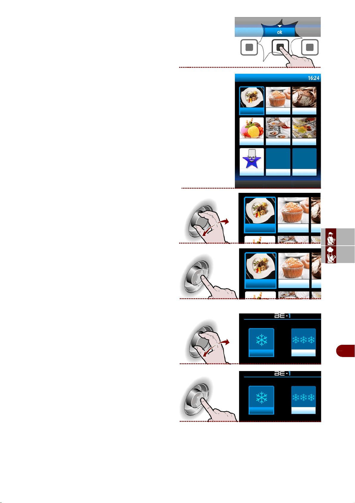
ES
CAN
DE
US
IT
3299702_rev.2.fIDM
Français
-
21
-
Manuel d’utilisation et d’installation
3–Presser la touche pour confirmer la fonction mise
en évidence. >>>
4–Sur l’afficheur apparaît la page. >>>
5–Sélectionner le secteur désiré en tournant la
manette. >>>
6–Appuyer sur la manette pour confirmer le choix
mis en évidence. >>>
7–Sélectionner la typologie de cycle désiré avec la
manette. >>>
8–Appuyer sur la manette pour entrer dans la typo-
logie de cycle sélectionné. >>>
programmes automatiques
restauration
patisserie
boulangerie
glacier
banqueting vacuum
prefere
restauration patisserie
restauration patisserie
restauration + restauration -
restauration + restauration -
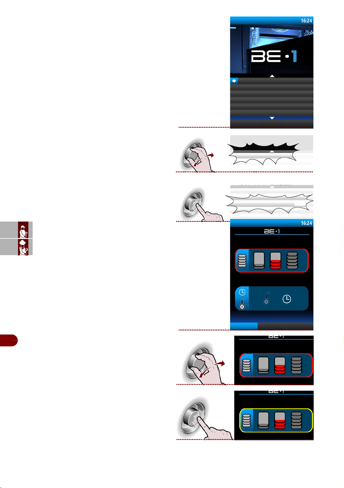
ES
CAN
DE
US
IT
3299702_rev.2.fIDM
Français
-
22
-
Manuel d’utilisation et d’installation
9–Sur l’afficheur apparaît la page. >>>
10–Sélectionner le cycle désiré en tournant la
manette. >>>
11–Appuyer sur la manette pour activer le cycle
sélectionné. >>>
12–Sur l’afficheur apparaît la page. >>>
13–Sélectionner de charge à traiter. >>>
14–Appuyer sur la manette pour confirmer le choix
mis en évidence. >>>
restauration +
BANQUETING
VIANDE
LASAGNE
VEAU NOIX
PATISSERIE CHAUDE
PÂTISSERIE SÉCHEZ
VIANDE
VIANDE
restauration +: VIANDE
rendre favoris
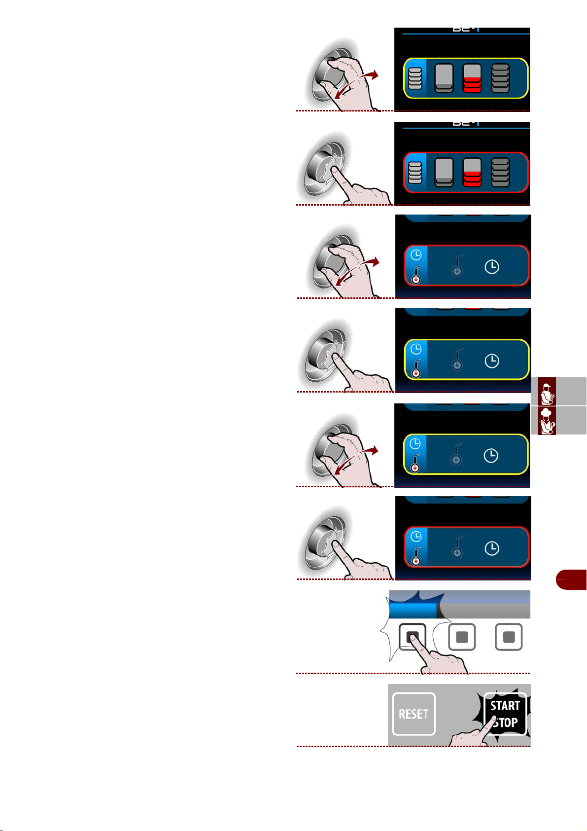
ES
CAN
DE
US
IT
3299702_rev.2.fIDM
Français
-
23
-
Manuel d’utilisation et d’installation
15–Sélectionner la quantité de charge à traiter, le
minimum, la moyenne, le maximum. >>>
16–Appuyer sur la manette pour confirmer le choix
mis en évidence. >>>
17–Sélectionner la typologie de réfrigération. >>>
18–Appuyer sur la manette pour confirmer le choix
mis en évidence. >>>
19–Sélectionner la typologie de réfrigération, avec
sonde ou temps. >>>
20–Appuyer sur la manette pour confirmer le choix
mis en évidence. >>>
-Il est possible faire devenir favoris
Pour la choisir comme programme préférée, ap-
puyer sur le bouton "rendre favoris" et procéder
comme indiqué page 13 (mode de saisie alpha-
numérique).
21–Appuyer sur la touche pour démarrer le cycle
sélectionné.
>>
rendre favoris
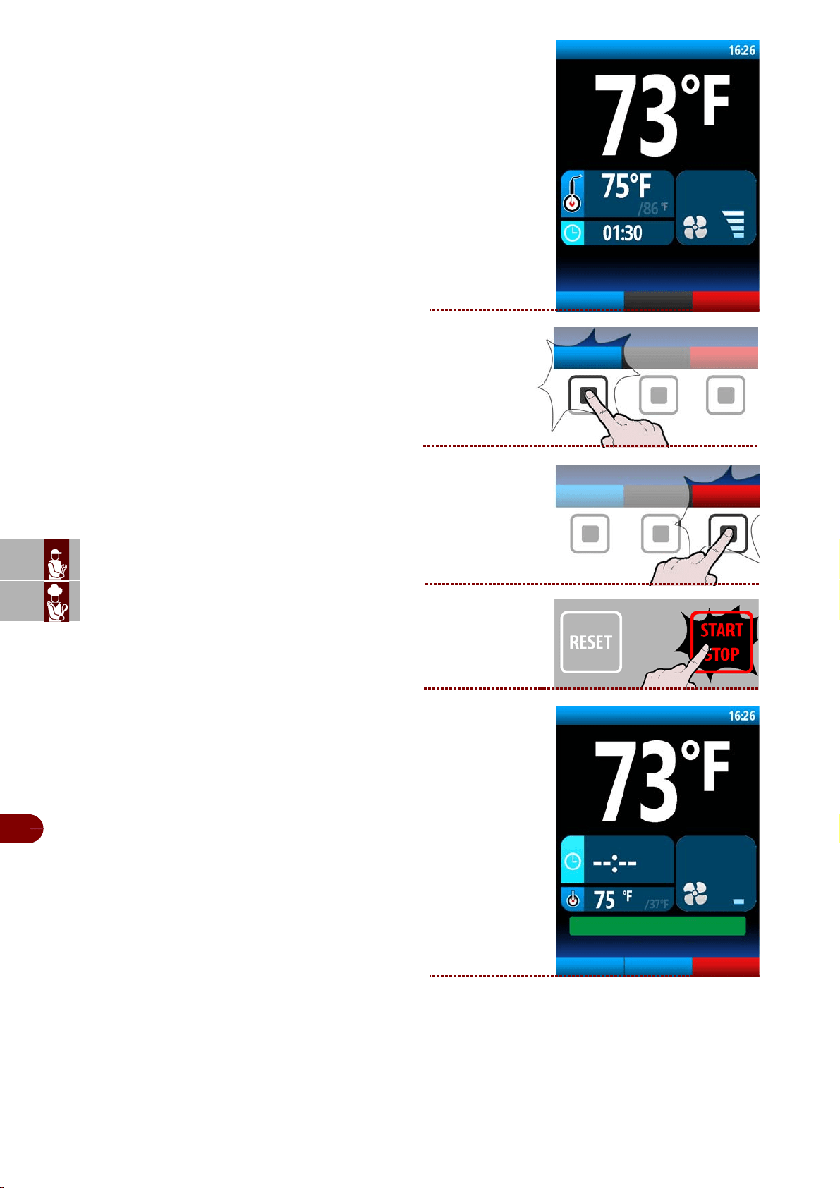
ES
CAN
DE
US
IT
3299702_rev.2.fIDM
Français
-
24
-
Manuel d’utilisation et d’installation
22–Sur l’afficheur apparaît la page. >>>
Pendant le cycle, il est possible de:
- de visualiser les paramètres default.
Remarque : les paramètres ne sont pas modi-
fiables.
-Sélectionner la fonction forno
.
-d'arrêter le cycle.
23–
Une fois le cycle terminé, une phase de conserva-
tion démarre automatiquement.
Sur l’afficheur apparaît la page. >>>
phase 1/3
four
afficher les
données
viande
afficher les
données
four
phase 3/3
four
Modifier les
paramètres
defrost
CYCLE TERMINE: CONSERVATION EN COURS
viande
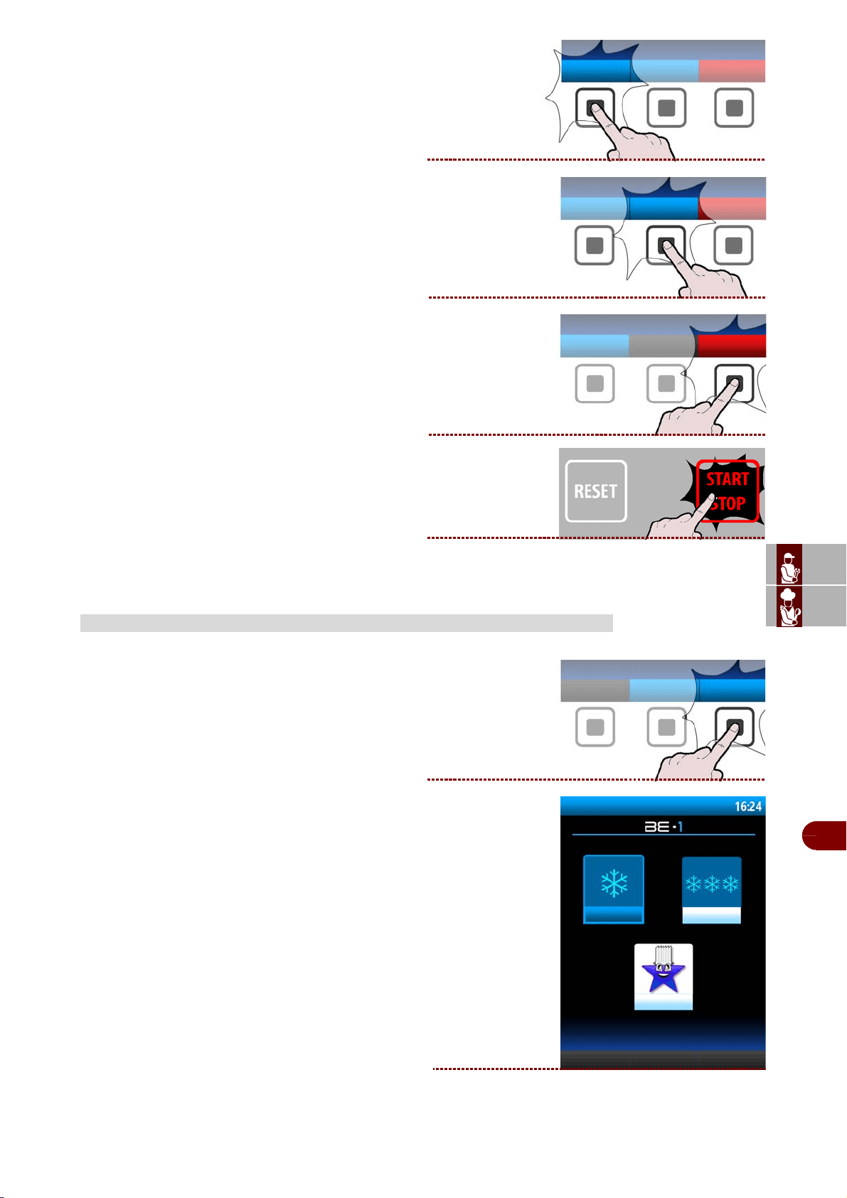
ES
CAN
DE
US
IT
3299702_rev.2.fIDM
Français
-
25
-
Manuel d’utilisation et d’installation
Pendant la conservation, il est possible de:
-visualiser et modifier les paramètres par défaut
(voir page 18).
Remarque : les paramètres modifiés seront
enregistrés uniquement pour le cycle en
cours.
-activer le dégivrage manuel.
Si cela n'est pas nécessaire, le dégivrage
manuel n'est pas effectué.
-sélectionner la fonction forno
.
-d'arrêter le cycle.
Procéder comme suit.
1–Depuis la page principale (home page refrodis-
seur), presser la bouton pour entrer dans les « pro-
grammes utilisateur » . >>>
2–Sur l’afficheur apparaît la page. >>>
PROGRAMMES UTILISATEUR
Modifier les
paramètres
defrost
four
programmes
utilisateur
programmes utilisateur
programmes +
Favoris
programmes -

ES
CAN
DE
US
IT
3299702_rev.2.fIDM
Français
-
26
-
Manuel d’utilisation et d’installation
3–Sélectionner la typologie de cycle désiré avec la
manette. >>>
4–Appuyer sur la manette pour entrer dans la typol-
ogie de cycle sélectionné. >>>
5–Sur l’afficheur apparaît la page. >>>
6–Sélectionner le cycle désiré en tournant la
manette. >>>
7–Appuyer sur la manette pour activer le cycle
sélectionné. >>>
1–Sélectionner le nom du programme avec la
manette.
>>>
2–Presser la touche.
>>
MODIFICA PROGRAMMES UTILISATEUR
programmes + programmes-
programmes + programmes-
C
programmes utilisateur
VIANDE
options
nouveau
programme
POISSON
VIANDE
VIANDE
VIANDE
options
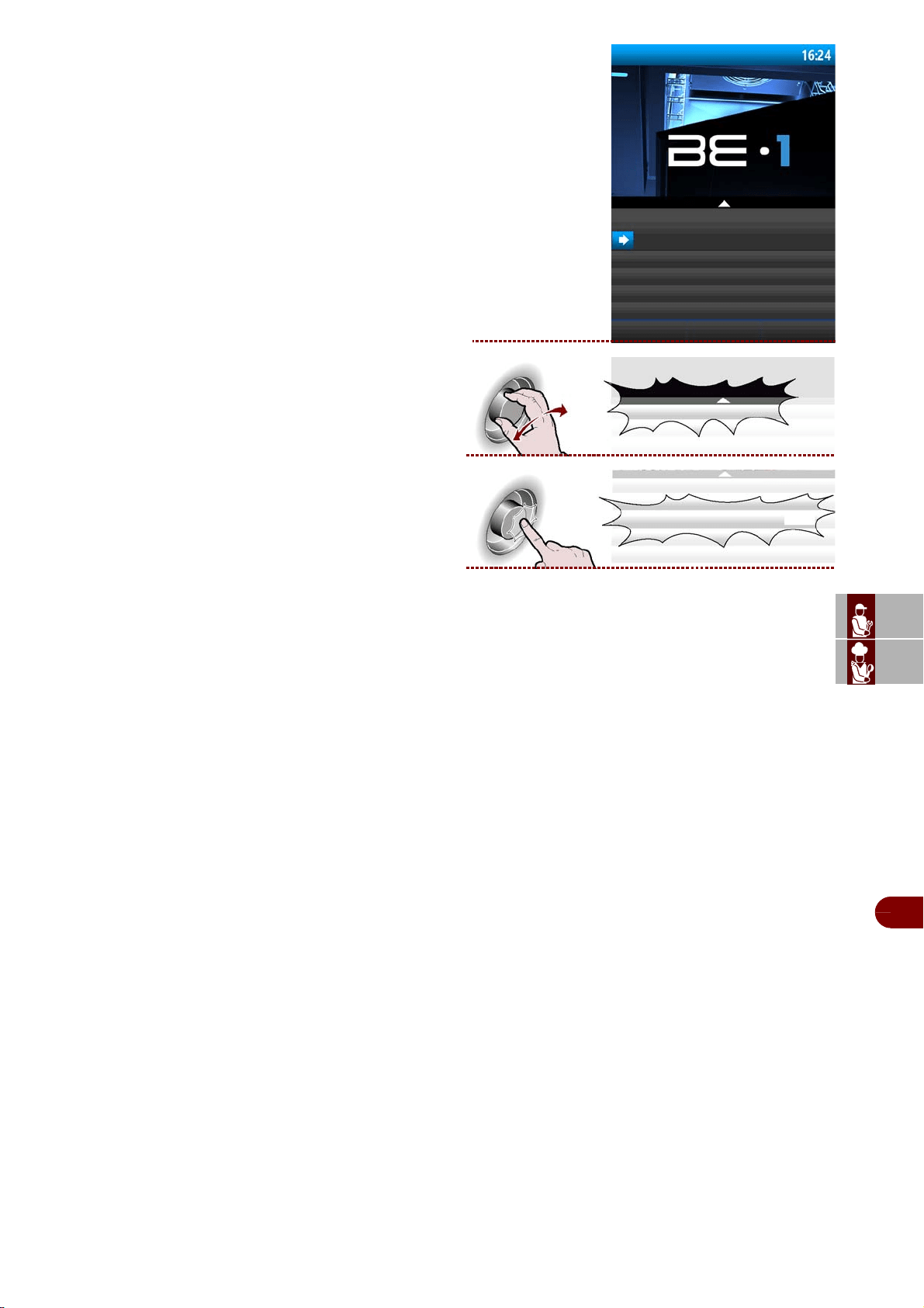
ES
CAN
DE
US
IT
3299702_rev.2.fIDM
Français
-
27
-
Manuel d’utilisation et d’installation
3–Sur l’afficheur apparaît la page. >>>
4–Sélectionner de la liste la fonction choisie avec la
manette >>>
5–Appuyer sur la molette pour confirmer. >>>
-RENOMMER: sert pour donner un nouveau nom au programme sélectionné (voir
page 13).
-MODIFIER/AFFICHER LES PHASES: sert pour afficher et/ou modifier les phases
du programme sélectionné.
-RENDRE FAVORIS: sert pour “enregistrer” le programme choisi dans la catégorie
favoris.
-COPIER : pour « copier-coller » le programme sélectionné et le renommer (voir
page 13).
-SUPPRIMER : pour supprimer le programme sélectionné.
programmes utilisateur
viande
renommer
modifier/afficher les phases
rendre favori
renommer
renommer
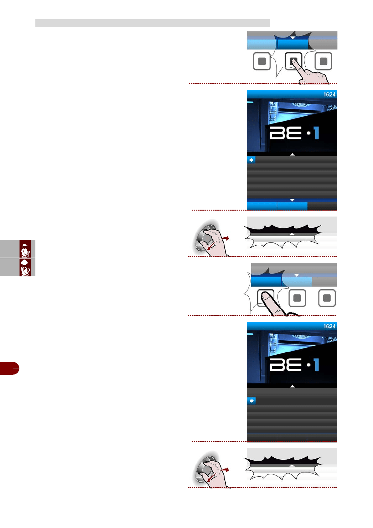
ES
CAN
DE
US
IT
3299702_rev.2.fIDM
Français
-
28
-
Manuel d’utilisation et d’installation
1–Presser la touche. >>>
2–Entrer le nom du nouveau programme (voir page
13)
Sur l’afficheur apparaît la page. >>>
3–Sélectionner le nom du nouveau programme
avec la manette.
>>>
4–Presser la touche.
>>
5–Sur l’afficheur apparaît la page. >>>
6–Sélectionner de la liste la fonction choisie avec la
manette. >>>
CRÉATION D’UN "NOUVEAU PROGRAMME" UTILISATEUR
nouveau
programme
programmes utilisateur
VIANDE
options
nouveau
programme
POISSON
POISSON
options
programmes utilisateur
viande
renommer
modifier/afficher les phases
rendre favori
modifier/afficher les phases
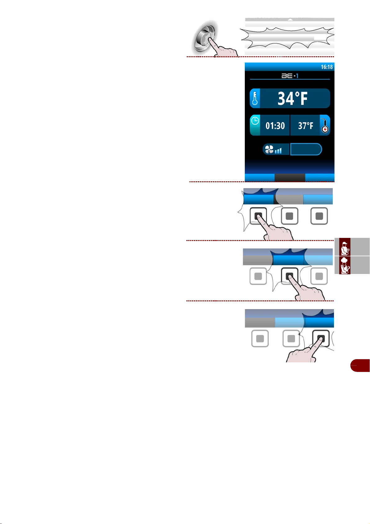
ES
CAN
DE
US
IT
3299702_rev.2.fIDM
Français
-
29
-
Manuel d’utilisation et d’installation
7–Appuyer sur la manette pour confirmer le choix
mis en évidence. >>>
8–Sur l’afficheur apparaît la page. >>>
Entrer toutes les caractéristiques du nouveau pro-
gramme (voir page 28).
9–Dans la création d’un nouveau programme, ilpeut
s’avérer nécessaire d’effectuer la cuisson enplus-
ieurs phases. Dans ce cas, presser la touche.
>>>
10–Sert il peut s’avérer nécessaire éliminer une
ouplusieurs phases d’une cuisson. Dans ce cas,
press-er la touche. >>>
11–Lorsque la programmation est terminée, pres-
serla touche pour enregistrer le nouveau programme
etretourner au menu principal. >>>
modifier/afficher les phases
phase 1/2
ajouter phase
enregister le
programme
POISSON
ajouter phase
éliminer phase
enregister le
programme
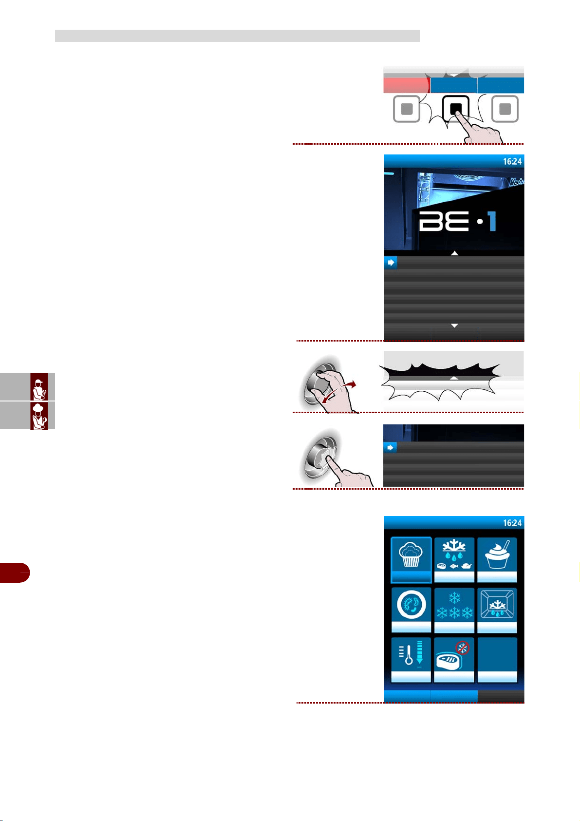
ES
CAN
DE
US
IT
3299702_rev.2.fIDM
Français
-
30
-
Manuel d’utilisation et d’installation
Procéder comme suit.
1–Depuis la page principale (home page refrodis-
seur), presser la bouton pour entrer dans le menu .
>>>
Sur l’afficheur apparaît la page. >>>
2–Sélectionner la fonction "fonctions spéciales"
avec la manette. >>>
3–Presser la touche pour confirmer la fonction mise
en évidence. >>>
4–Sur l’afficheur apparaît la page. >>>
FONCTIONS SPÉCIALES
menù
haccp
programmes automatiques
fonctions spéciales
configurations
service
Recevoir/transmettre les données
fonctions spéciales
fonctions spéciales
fonctions spéciales
Levain
décongeler
boîte de yaourt
parasites
conservation degivrage
refroidissment
ifr
chauffage de
sonde
sterilisation
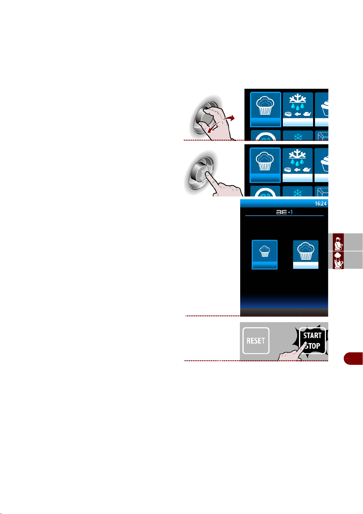
ES
CAN
DE
US
IT
3299702_rev.2.fIDM
Français
-
31
-
Manuel d’utilisation et d’installation
Levain
Les cycles de levage et d'arrêt de levage sont automatiques. Durant le cycle, il est
possible de modifier les paramètres pour choisir la température ou l'heure à laquelle
vous souhaitez trouver les aliments levés et prêts à utiliser.
L'utilisateur a la possibilité de modifier uniquement la date de fin de cycle en interve-
nant sur la date affichée sur la page-écran du cycle en cours, mais seulement durant
la première phase (maintien), en programmant tout simplement le moment où il sou-
haite trouver les produits parfaitement levés..
1–Sélectionner la fonction choisie avec la molette.
>>>
2–Appuyer sur la manette pour confirmer le choix
mis en évidence. >>>
-Sur l’afficheur apparaît la page.
3–
Appuyer sur la bouton pour démarrer le cycle sélec-
tionné.
>>
Levain
Levain
Levain
Levain
arrête la levain
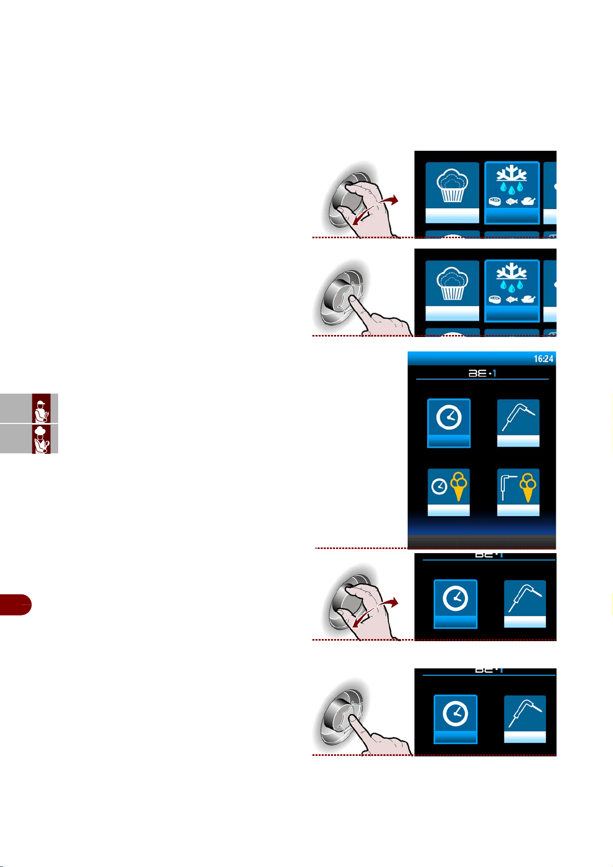
ES
CAN
DE
US
IT
3299702_rev.2.fIDM
Français
-
32
-
Manuel d’utilisation et d’installation
Décongeler
Les cycles de décongélation, avec sonde ou par temps, sont automatiques. Durant le
cycle, il est possible de modifier les paramètres et de choisir la température ou l'heure
à laquelle vous souhaitez trouver les aliments décongelés et prêts à utiliser.
En cas de décongélation par temps, l'utilisateur a la possibilité de modifier uniquement
la date de fin de cycle en intervenant sur la date affichée sur la page-écran du cycle
en cours; cette action est valide uniquement si elle est réalisée durant la première
phase (maintien).
1–Sélectionner la fonction choisie avec la molette.
>>>
2–Appuyer sur la manette pour confirmer le choix
mis en évidence. >>>
-Sur l’afficheur apparaît la page .
3–Sélectionner la typologie de désiré avec la man-
ette. >>>
4–Appuyer sur la manette pour entrer dans la typol-
ogie de cycle sélectionné. t . >>>
Remarque : le cycle démarre automatiquement.
Décongeler
Décongeler
Décongeler
Temps
Sonde
glacier temps
glacier sonde
Temps Sonde
Temps Sonde
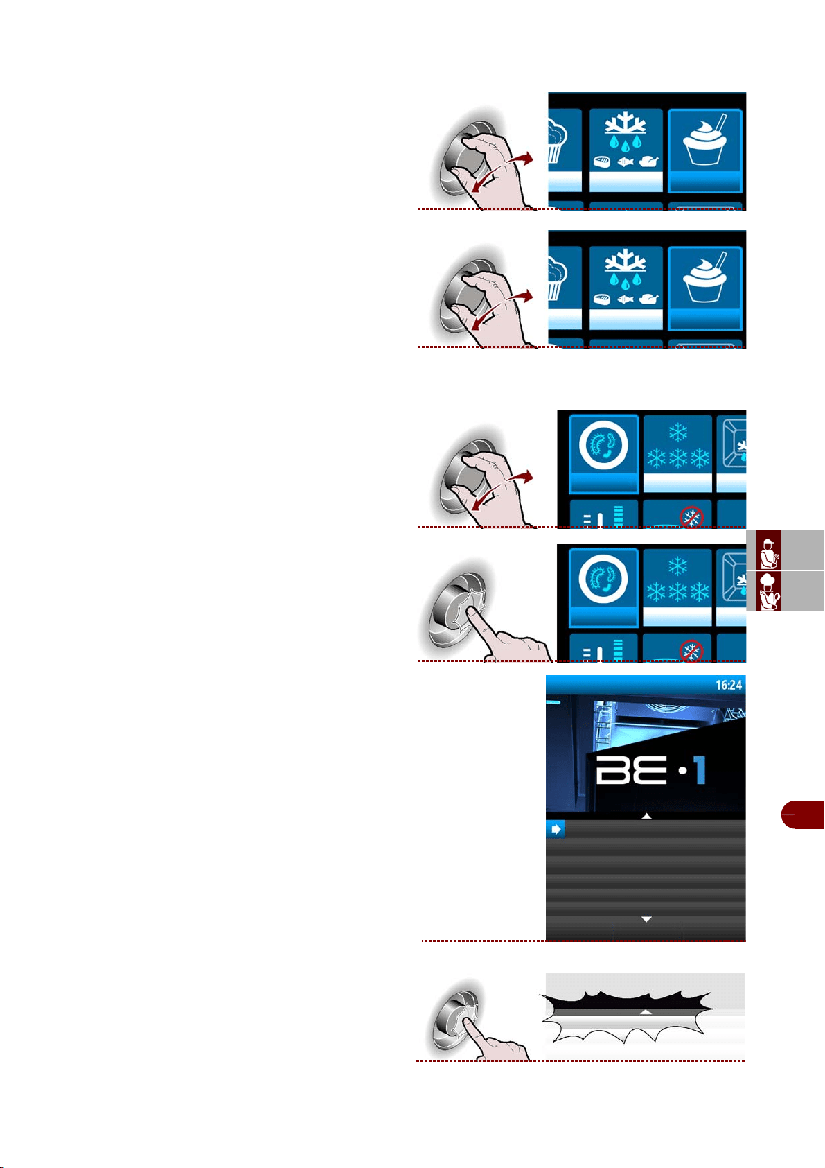
ES
CAN
DE
US
IT
3299702_rev.2.fIDM
Français
-
33
-
Manuel d’utilisation et d’installation
Boîte de yaourt
Cycle dédié à la préparation de yaourt.
1–Sélectionner la fonction choisie avec la molette.
. >>>
2–Appuyer sur la manette pour confirmer le choix
mis en évidence. >>>
Remarque : le cycle démarre automatiquement.
Parasites
1–Sélectionner la fonction choisie avec la molette.
>>>
2–Appuyer sur la manette pour confirmer le choix
mis en évidence. >>>
-Sur l’afficheur apparaît la page .
3–Sélectionner la typologie de cycle désiré avec la
manette. >>>
boîte de yaourt
boîte de yaour
parasites
parasites
parasites
anisakis 15h
anisakis 24h
opistorkis 24h
anisakis 15h
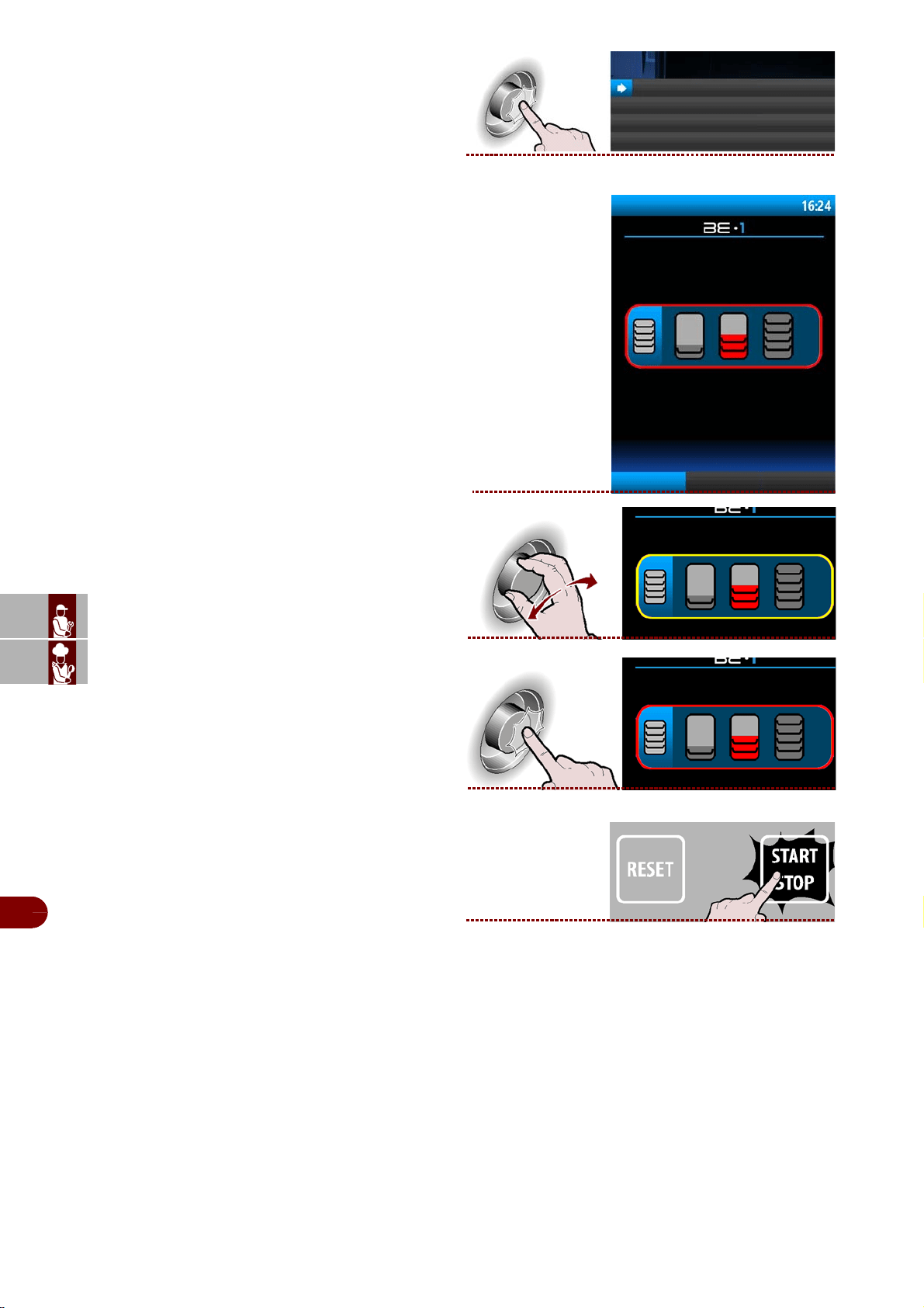
ES
CAN
DE
US
IT
3299702_rev.2.fIDM
Français
-
34
-
Manuel d’utilisation et d’installation
4–Appuyer sur la manette pour entrer dans la
typologie de cycle sélectionné. >>>
5–Sur l’afficheur apparaît la page . >>>
6–Sélectionner la quantité de charge à traiter, le
minimum, la moyenne, le maximum. >>>
7–Appuyer sur la manette pour confirmer le choix
mis en évidence. >>>
8–
Appuyer sur la bouton pour démarrer le cycle sélec-
tionné.
>>>
anisakis 15h
ANISAKIS 15h
Ajouter aux
favoris
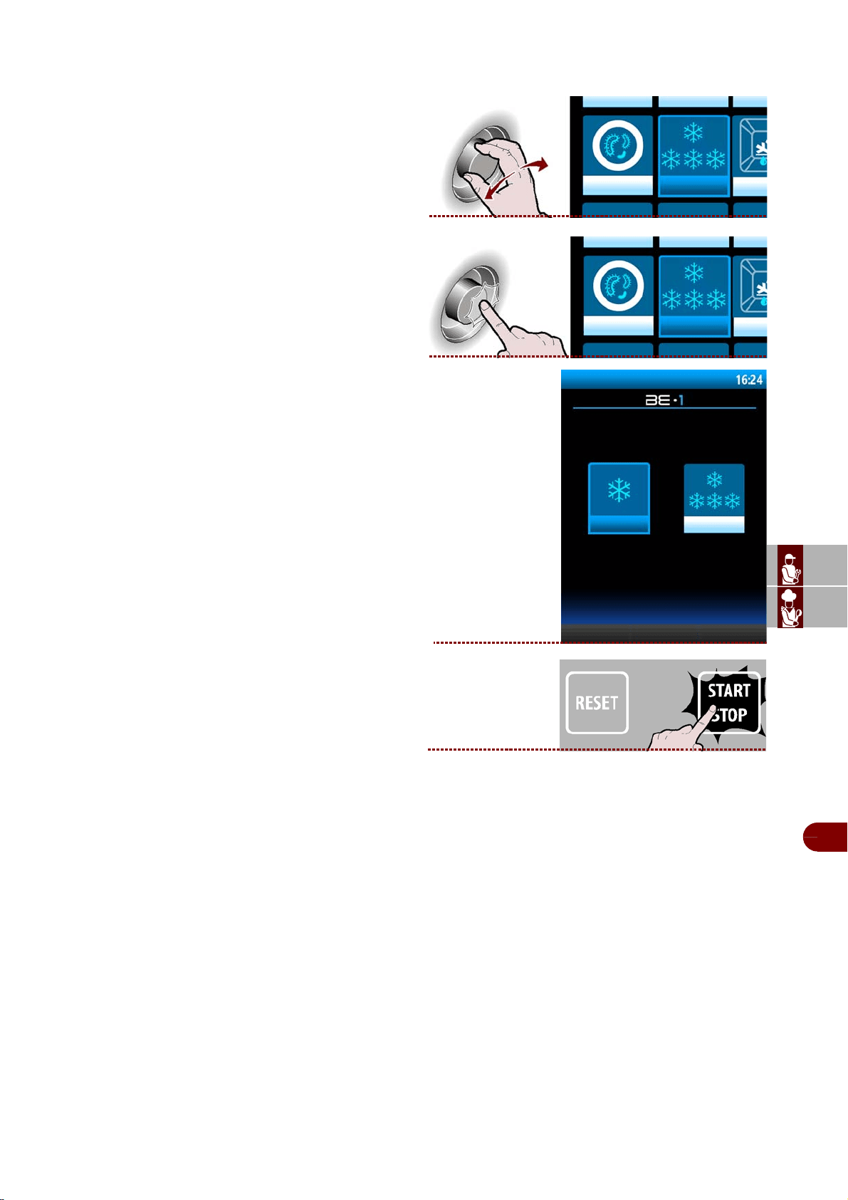
ES
CAN
DE
US
IT
3299702_rev.2.fIDM
Français
-
35
-
Manuel d’utilisation et d’installation
Conservation
Il sert à conserver les aliments à une température positive ou négative.
1–Sélectionner la fonction choisie avec la molette.
. >>>
2–Appuyer sur la manette pour confirmer le choix
mis en évidence. >>>
-Sur l’afficheur apparaît la page .
3–
Appuyer sur la bouton pour démarrer le cycle sélec-
tionné. >>>
conservation
conservation
conservazione
conservation+ conservation-
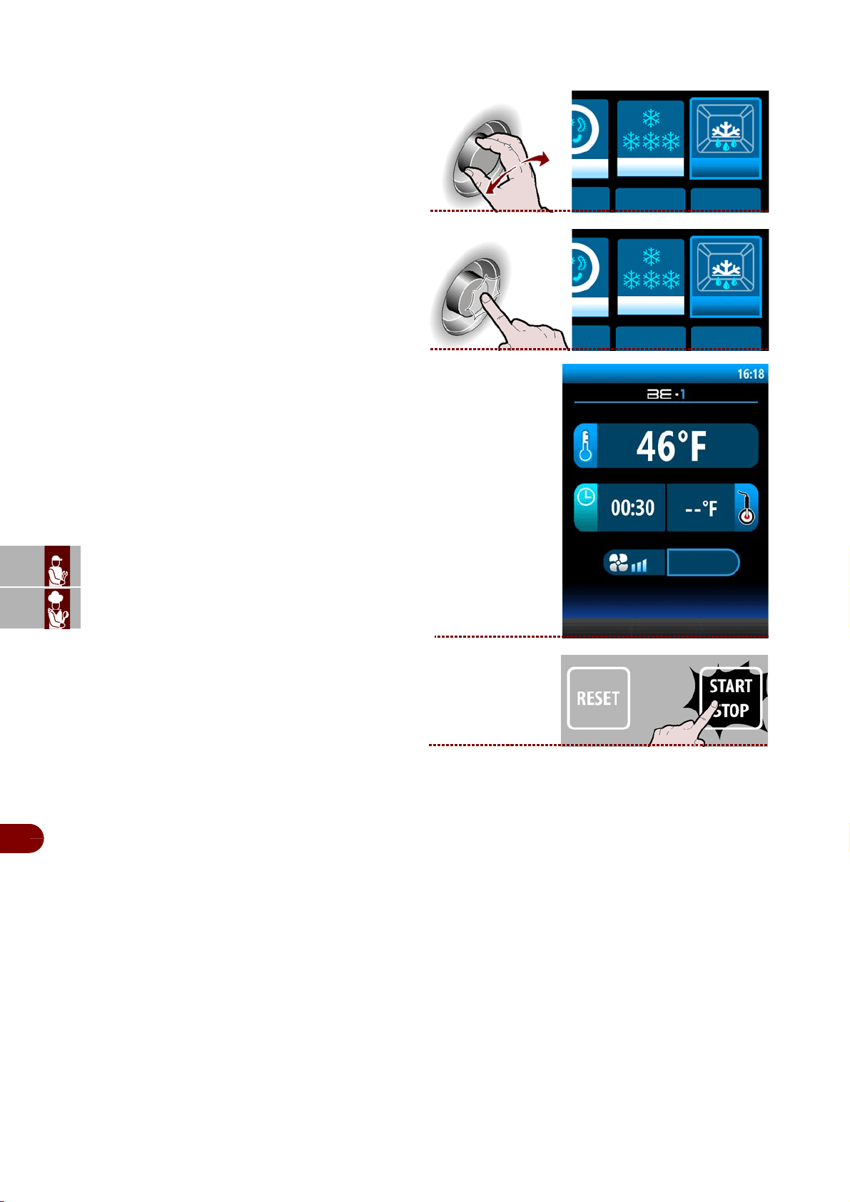
ES
CAN
DE
US
IT
3299702_rev.2.fIDM
Français
-
36
-
Manuel d’utilisation et d’installation
Degivrage
Il sert à optimiser le fonctionnement de la cellule de refroidissement au cycle suivant.
1–Sélectionner la fonction choisie avec la molette.
>>>
2–Appuyer sur la manette pour confirmer le choix
mis en évidence. >>>
-Sur l’afficheur apparaît la page..
3–Appuyer sur la bouton pour démarrer le cycle
sélectionné. >>>
degivrage
degivrage
phase 1/2
degivrage
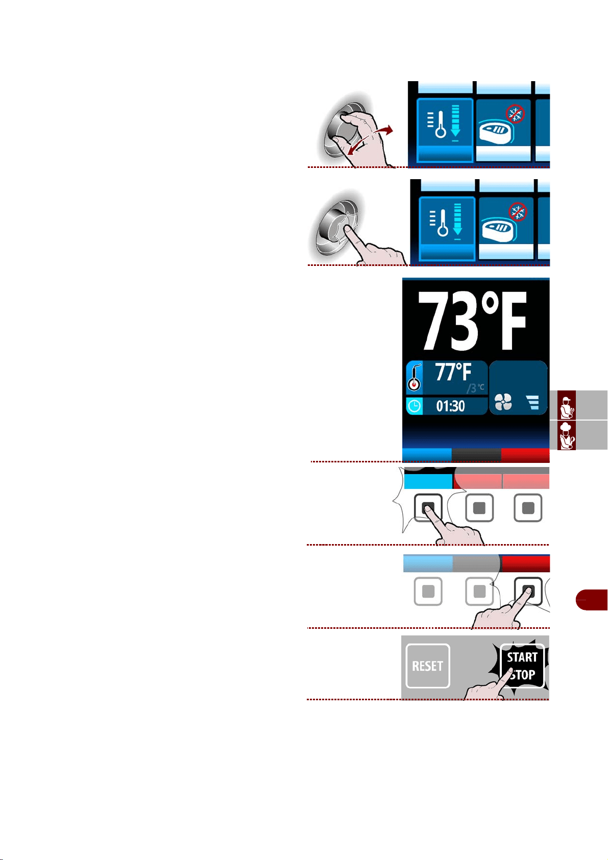
ES
CAN
DE
US
IT
3299702_rev.2.fIDM
Français
-
37
-
Manuel d’utilisation et d’installation
Refroidissement
On conseille de démarrer un cycle de refroidissement avant de sélectionner toute
sorte de cycle de refroidissement rapide.
1–Sélectionner la fonction choisie avec la molette.
>>>
2–Appuyer sur la manette pour confirmer le choix
mis en évidence. >>>
3– Sur l’afficheur apparaît la page. >>>
Remarque : le cycle démarre automatiquement.
Pendant le cycle, il est possible:
-visualiser et modifier les paramètres par défaut
(voir page 19).
Remarque : les paramètres modifiés seront
enregistrés uniquement pour le cycle en
cours.
- Sélectionner la fonction four
.
-d'arrêter le cycle.
refroidissment
refroidissment
phase 1/2
four
Modifier les
paramètres
Modifier les
paramètres
four
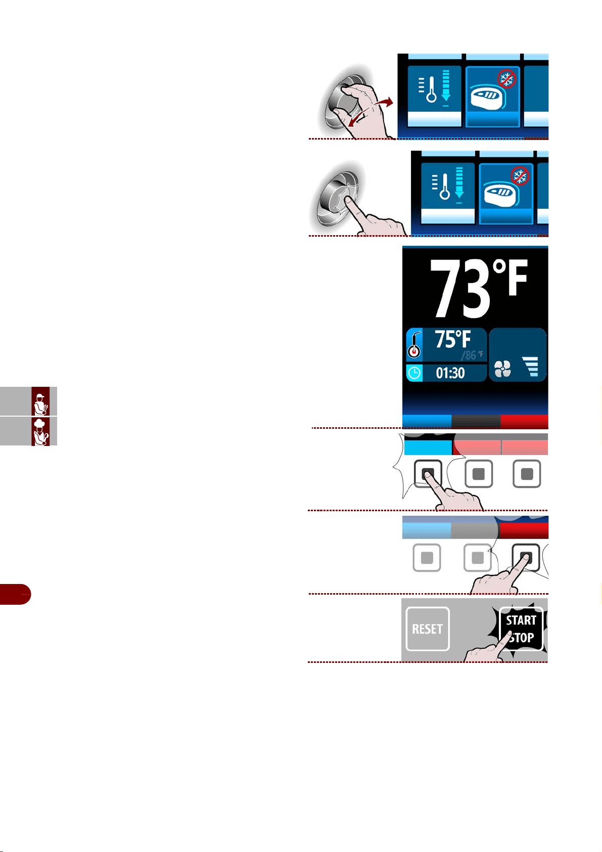
ES
CAN
DE
US
IT
3299702_rev.2.fIDM
Français
-
38
-
Manuel d’utilisation et d’installation
Ifr
1–Sélectionner la fonction choisie avec la molette.
>>
2–Appuyer sur la manette pour confirmer le choix
mis en évidence. >>
3– Sur l’afficheur apparaît la page. >>>
Remarque: le cycle démarre automatiquement.
Pendant le cycle, il est possible:
-visualiser et modifier les paramètres par défaut
(voir page 13).
Remarque: les paramètres modifiés seront en-
registrés uniquement pour le cycle en cours.
- sélectionner la fonction four
.
d'arrêter le cycle.
ifr
ifr
phase 1/1
four
modify
parameters
modifica
parametri
four
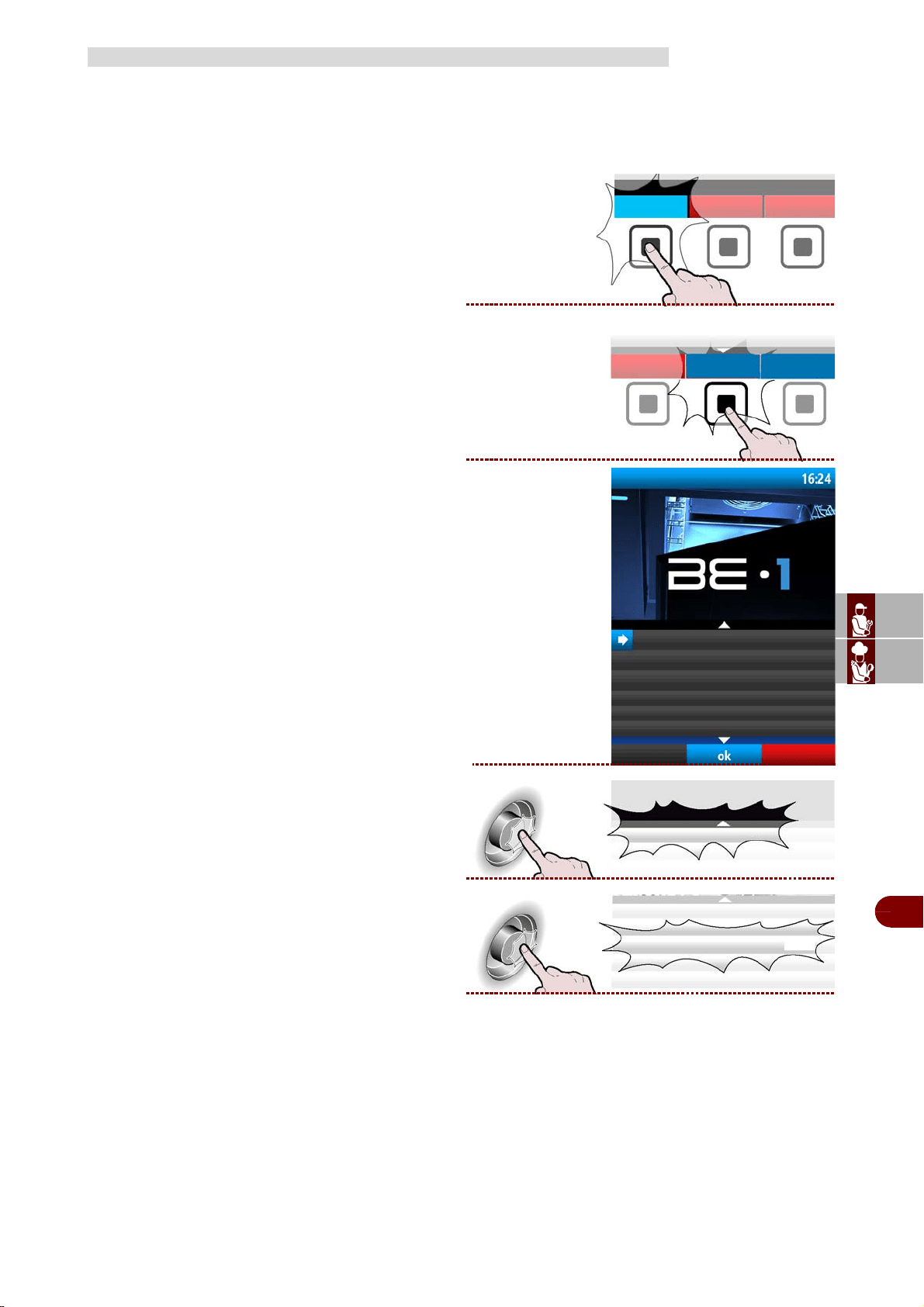
ES
CAN
DE
US
IT
3299702_rev.2.fIDM
Français
-
39
-
Manuel d’utilisation et d’installation
Il est possible de choisir de gérer le contrôle du cycle en mode automatique ou par le
choix, par temps ou avec sonde au cœur, de l’opérateur (MANUEL).
L'appareil gère par défaut le contrôle du cycle en mode automatique. (AUTO).
Procéder comme suit.
1–Depuis la page principale (home page four),
presser la bouton pour entrer des modalité de refro-
disseur. >>>
2–Depuis la page principale (home page refrodis-
seur) presser le bouton pour entrer dans le menu.
. >>>
Sur l’afficheur apparaît la page. >>>
3–Sélectionner la fonction "configurations" avec la
manette. >>>
4–Presser la touche pour confirmer la fonction mise
en évidence. >>>
CONFIGURATIONS
refrodisseur
menù
programmes automatiques
fonctions spéciales
configurations
service
haccp
Recevoir/transmettre les données
configurations
configurations
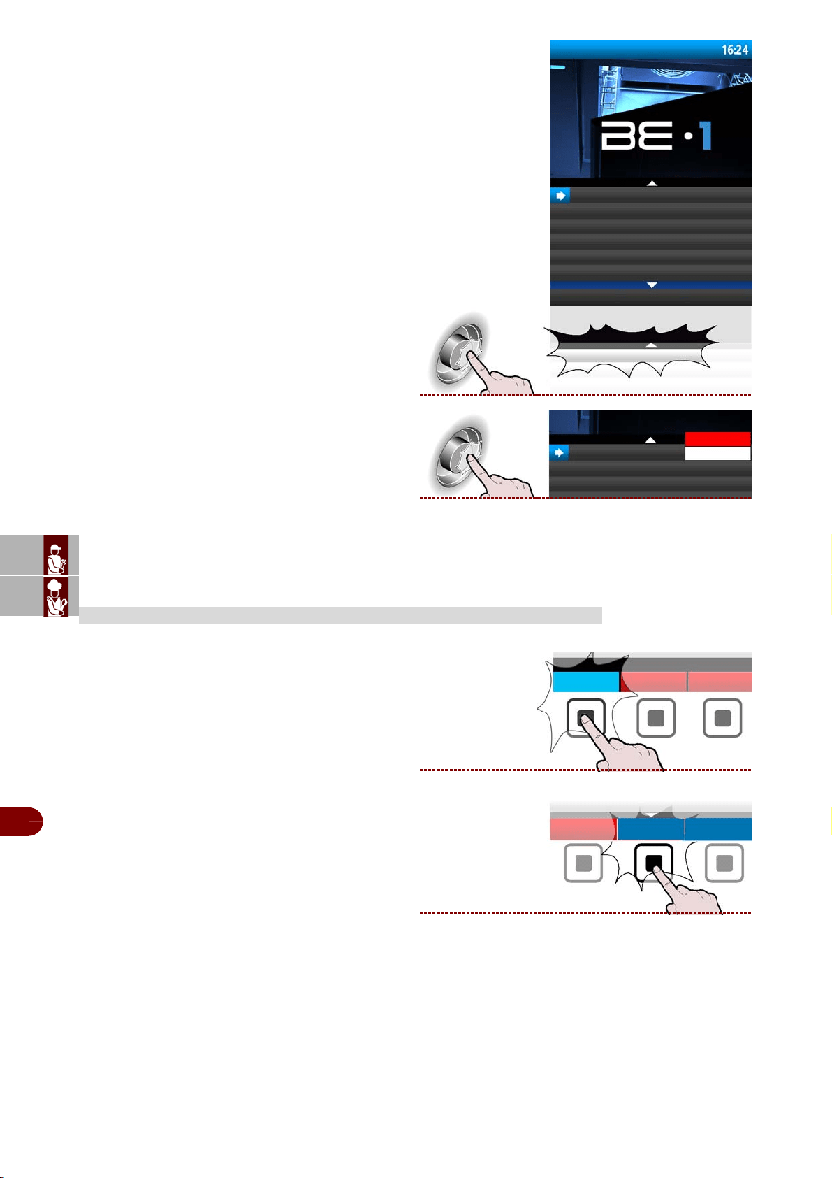
ES
CAN
DE
US
IT
3299702_rev.2.fIDM
Français
-
40
-
Manuel d’utilisation et d’installation
5–Sur l’afficheur apparaît la page. >>>
6–Appuyer sur la manette pour confirmer le choix
mis en évidence. >>>
7–Appuyer sur la manette pour confirmer le choix
mis en évidenceAppuyer sur la manette pour con-
firmer le choix mis en évidence. >>>
Procéder comme suit.
1–Depuis la page principale (home page four),
presser la bouton des modalité de refrodisseur. >>>
2–Depuis la page principale (home page refrodis-
seur), presser la bouton pour entrer dans le menu.
. >>>
SERVICE
controle sonde automatique
controle cycle
controle sonde
automatique
manuel
refrodisseur
menù
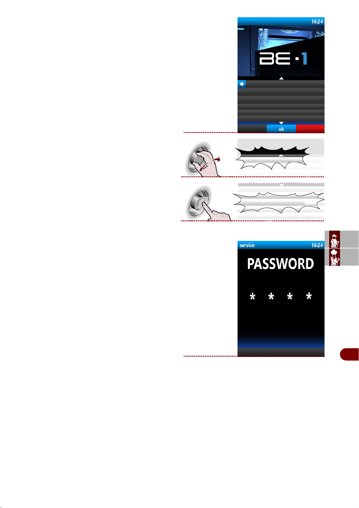
ES
CAN
DE
US
IT
3299702_rev.2.fIDM
Français
-
41
-
Manuel d’utilisation et d’installation
Sur l’afficheur apparaît la page. >>>
3–Sélectionner la fonction "service" avec la man-
ette. >>>
4–Presser la touche pour confirmer la fonction mise
en évidence. >>>
Sur l’afficheur apparaît la page. >>>
-Tourner la manette pour saisir le mot de passe
fourni par le fabricant.
-Appuyer sur la manette pour confirmer.
programmes automatiques
fonctions spéciales
configurations
service
haccp
Recevoir/transmettre les données
service
service
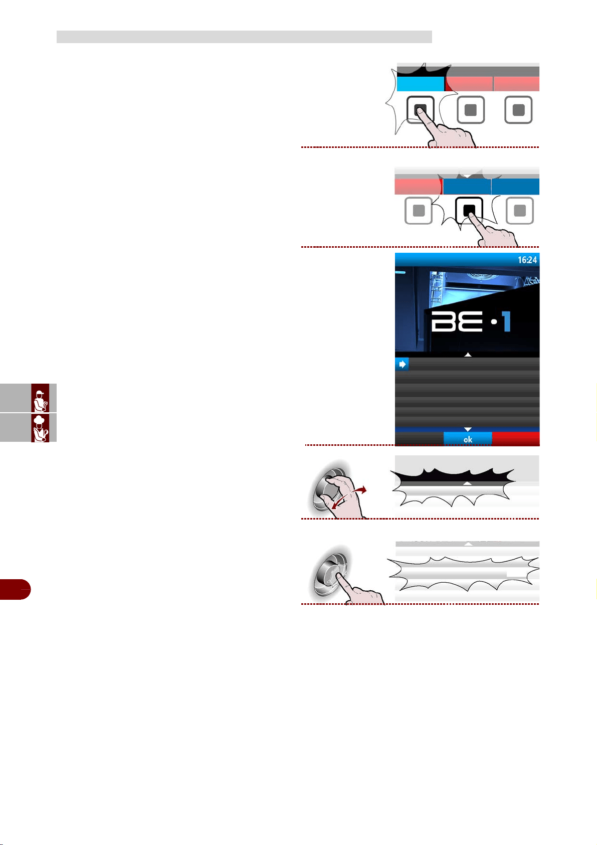
ES
CAN
DE
US
IT
3299702_rev.2.fIDM
Français
-
42
-
Manuel d’utilisation et d’installation
Procéder comme suit.
1–Depuis la page principale (home page four),
presser la bouton des modalité de refrodisseur. >>>
2–Depuis la page principale (home page refrodis-
seur), presser la bouton pour entrer dans le menu.
. >>>
Sur l’afficheur apparaît la page. >>>
3–Sélectionner la fonction "haccp" la manette..
>>>
4–Presser la bouton pour confirmer la fonction mise
en évidence. >>>
HACCP
refrodisseur
menù
programmes automatiques
fonctions spéciales
configurations
service
haccp
Recevoir/transmettre les données
haccp
haccp
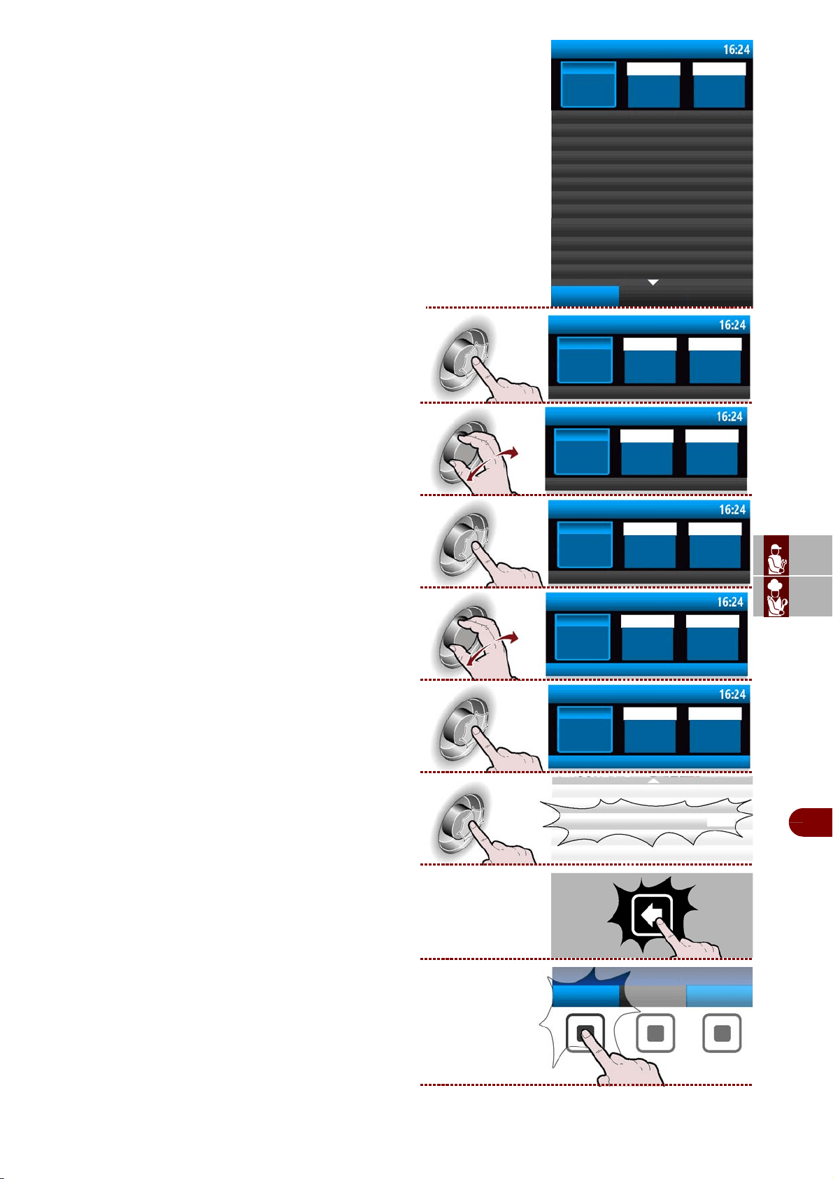
ES
CAN
DE
US
IT
3299702_rev.2.fIDM
Français
-
43
-
Manuel d’utilisation et d’installation
Sur l’afficheur apparaît la page . >>>
La page sert à visualiser les données de Refroidisse-
ments effectués (et non mesurés) et les alarmes in-
tervenues.
5–Appuyer sur la manette pour modifier le jour
(mois ou année). >>>
6–Tourner la manette pour configurer le jour (mois
ou année). >>>
7–Appuyer sur la manette pour confirmer la valeur
configurée. >>>
8–Tourner la manette pour sélectionner “Acquisi-
tions”. >>>
9–Presser la manette pour accéder aux données.
>>>
10–Appuyer sur la manette pour confirmer la fonc-
tion mise en évidence. >>>
11–Presser la touche pour retourner à la page
précédente. >>>
12–Appuyer la touche pour visualiser les alarmes
intervenues >>>
haccp
Jour
18
Acquisitions
refroidissment
start
11:39 11:40
Mois
Année
12 2017
stop
11:40 11:40
11:42 11:46
11:54 11:58
ifr
ifr
ifr
Afficher les
alarmes
haccp
Jour
18
Mois Année
12 2017
haccp
Jour
16
Mois Année
12 2017
haccp
giorno
16
mese anno
12 2017
Acquisitions
haccp
Jour
Mois Année
Acquisitions
haccp
Jour
Mois Année
ifr
Afficher les
alarmes

ES
CAN
DE
US
IT
3299702_rev.2.fIDM
Français
-
44
-
Manuel d’utilisation et d’installation
Procéder comme suit.
1–Depuis la page principale (home page four),
presser la bouton des modalité de refrodisseur. >>>
2–Depuis la page principale (home page refrodis-
seur), presser la bouton pour entrer dans le menu.
. >>>
Sur l’afficheur apparaît la page. >>>
3–Sélectionner la fonction "Recevoir/transmettre les
données" avec la manette. >>>
4–Presser la bouton pour confirmer la fonction mise
en évidence. >>>
RECEVOIR/TRANSMETTRE LES DONNÉES
refrodisseur
menù
programmes automatiques
fonctions spéciales
configurations
service
haccp
Recevoir/transmettre les données
Recevoir/transmettre les données
Recevoir/transmettre les données
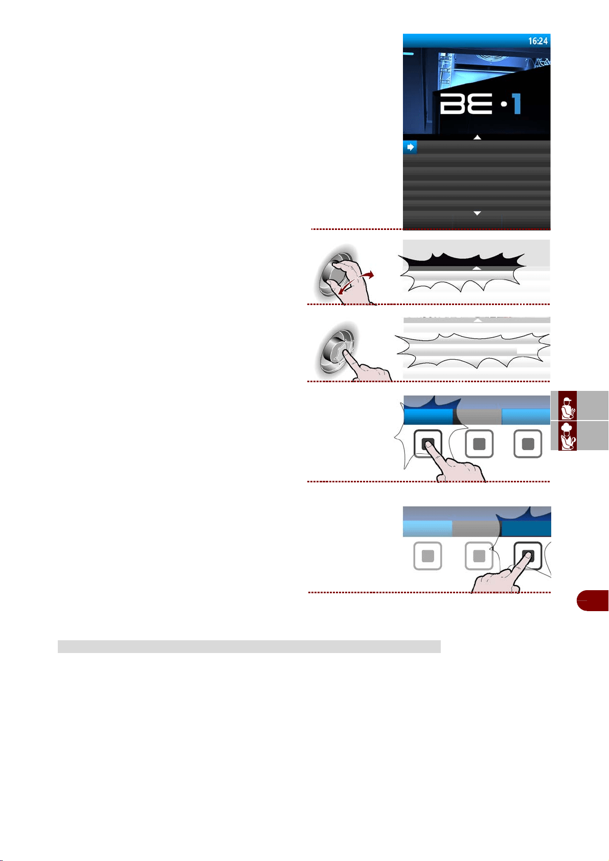
ES
CAN
DE
US
IT
3299702_rev.2.fIDM
Français
-
45
-
Manuel d’utilisation et d’installation
Sur l’afficheur apparaît la page . >>>
La page sert à télécharger les programmes utilisa-
teur ou données HACCP de la cellule de refroidisse-
ment vers une unité de mémoire externe ou bien
pour charger les programmes utilisateur d'une unité
de mémoire externe vers la cellule de refroidisse-
ment.
5–Sélectionner la fonction "transmettre pro-
grammes utilisateur" avec la manette. >>>
6–Presser la manette pour confirmer la fonction
mise en évidence. >>>
7–Presser le bouton « sélectionner tous » pour
sélectionner tous les programmes de Refroidisse-
ment à charger et/ou télécharger. t >>>
En alternative, sélectionner chaque programme à
charger/télécharger.
8–Presser le bouton pour faire démarrer l'opération
. >>>
Selon la quantité de données à télécharger/charger,
l'opération peut mettre plusieurs minutes.
En cas de longues périodes d'inactivité de l'appareil et pour le maintenir dans les meil-
leures condition-s, agissez de la manière suivante:
1–Portez l'interrupteur du courant en position OFF.
2–Enlevez la fiche de la prise.
3–Videz l'appareil et nettoyez-le comme décrit au chapitre "NETTOYAGE”.
4–Laissez la porte entrouverte pour éviter la formation de mauvaises odeurs.
5–Couvrez le groupe compresseur par une toile de nylon pour le protéger de la pous-
sière.
6–Recouvrir l'appareil d'une protection et laisser quelques fentes pour la circula-
tionde l'air.
INUTILISATION PROLONGÉE DE L’APPAREIL
transmettre programmes utilisateur
recevoir programmes utilisateur
Transmettre les données HACCP
transmettre programmes utilisateur
transmettre programmes utilisateur
sélectionner
tout
menù
exécuter
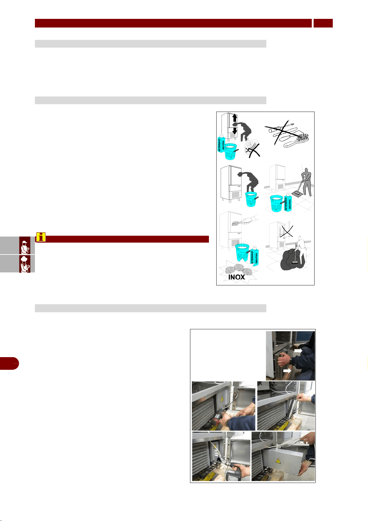
ES
CAN
DE
US
IT
3299702_rev.2.fIDM
Français
-
46
-
Manuel d’utilisation et d’installation
Maintenir l'appareil en parfait état de fonctionnement en effectuant les opérationsd'en-
tretien programmé prévues par le fabricant. Un bon entretien permettra d'obtenirles
meilleures performances, une plus longue durée et un maintien constant des con-di-
tions de sécurité requises.
L'appareil est construit en acier INOX AISI 304.
Pour le nettoyage et l'entretien des parties en acier inox, tenez-
vous à ce qui est spécifié ci-dessous, en tenant compte que la
règle fondamentale est de garantir la non toxicité et le maximum
d'hygiène des produits traités.
Ne pas utiliser d’eau de Javel.Avant d'utiliser n'importe quel pro-
duit détergent informez-vous toujours chez votre fournisseur
habituel sur le produit détergent neutre le plus indiqué ne pro-
duisant pas de corrosions sur l'acier.
Avant d’utiliser tout produit détergent informez vous auprès de
votre fournisseur sur le genre de détergent neutre sans chlore
afin d’éviter des corrosions sur l’acier.
En cas de rayures sur les surfaces il est nécessaire de les polir
avec de la laine d'ACIER INOX très fine ou une éponge abra-
sive synthétique fibreuse en frottant dans le sens du satinage.
Important
Pour le nettoyage de l'ACIER INOX n'utilisez jamais de
pailles de fer et ne les laissez pas posées sur les surfaces
de l'appareil car de légers dépots ferreux pourraient rester
sur les surfaces et provoquer des formations de rouille et
compromettre l'hygiène.
Les informations et les instructions de cette section
sont réservées au personnel spécialisé et autorisé à
intervenir sur les composants de l'appareil.
–Portez l'interrupteur du courant en position OFF.
–Enlevez la fiche de la prise.
Pour accéder au tableau électrique:
Mod. B151MU - B152MU
–Décrocher la protection frontale en la tirant vers soi.
–Retirer les vis du panneau de fermeture.
–Retirer le panneau de fermeture.
–Retirer les vis de blocage du tableau électrique.
–Déplacer le long du coulisseau le boîtier du tableau
électrique.
ENTRETIEN
5
RECOMMANDATIONS POUR L’ENTRETIEN
ENTRETIEN ACIER INOX
ENTRETIEN DU TABLEAU ÉLECTRIQUE
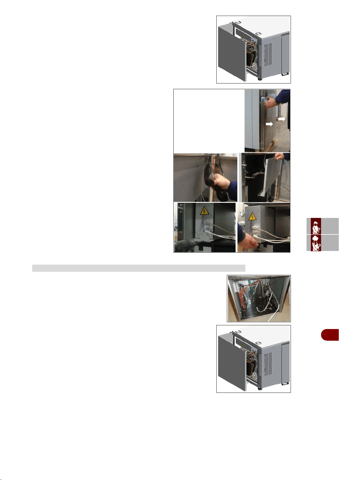
ES
CAN
DE
US
IT
3299702_rev.2.fIDM
Français
-
47
-
Manuel d’utilisation et d’installation
Mod. B151HU
Retirer le panneau latéral en desserrant les vis.
Mod. B1101SU
–Décrocher la protection frontale en la tirant vers soi.
–Retirer les vis du panneau de fermeture.
–Retirer le panneau de fermeture.
–Retirer les vis de blocage du tableau électrique.
–Déplacer le long du coulisseau le boîtier du tableau
électrique.
Mod. B151MU – B151MU - B1101SU
–Pour accede à l'installation de condensation, retirer la grille de protection
postérieure en desserrant les vis.
Mod. B151HU
–Pour accéder à l'installation de condensation, retirer le panneau
latéral en desserrant les vis.
ENTRETIEN DE L’INSTALLATION DE CONDENSATION
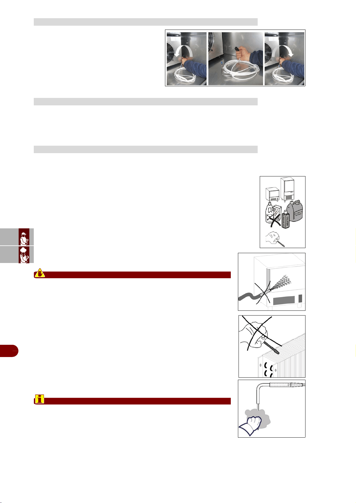
ES
CAN
DE
US
IT
3299702_rev.2.fIDM
Français
-
48
-
Manuel d’utilisation et d’installation
–Tourner à gauche dévissant complètement le
connecteur à débrancher le câble de la sonde à
cœur.
–Remplacer la sonde à cœur en vissant le con-
necteur à fond.
Étant donné que l'appareil est utilisé pour la préparation de produits alimentaires pour
l'homme, il faut faire attention à tout ce qui concerne l'hygiène; l'appareil et tout ce qui
l'entoure doivent toujours être très propres.
On doit nettoyer l’intérieur de l’enceinte de refroidissement rapide claque jour.
L’enceinte et ses éléments sont concus pour permettre de laver et nettoyer tous les
éléments.
–Avant le nettoyage on doit dégivrer l’appareil et enlever le bassin de décharge à
l’intérieur de l’appareil.
–Tournez l'interrupteur général en position OFF.
–Nettoyez tous les éléments (en acier inox, chromés, en plastique ou vernis) avec
de l’eau tiéde et du détergent.
–Ensuite rincez et essuyez soingneusement. N’utilisez pas de substances abra-
sives ou de solvants chimiques
Attention
Ne pas laver l'appareil au jet d'eau à haute pression.
Ne pas utiliser des objets pointus ou des substances abrasives.
–On peut nettoyer l’évaporateur à l’intérieur en desserrant les mopettes et
tournant le panneau de protection.
–Il faut laver simplement avec de l’eau tiéde le joint de la porte et l’essuyer
soigneusement en le frottant avec un chiffon sec. Pendant les opérations de
nettoyage il faut se protéger avec des gants.
–La sonde doit être nettoyée à la main, avec de l’eau tiède et du détergent
neutre ou des produits ayant une biodégradabilité supérieure à 90%; la
sonde doit être rincée avec de l’eau propre et une solution hygiénique. Ne
pas utiliser des détergents à base de solvants (trichloréthylène etc.) ou
poudres abrasives.
Important
La sonde ne doit pas être nettoyée avec de l’eau bouillante.
ENTRETIEN DE LA SONDE À COEUR
RECOMMANDATIONS POUR LE NETTOYAGE
NETTOYAGE ENCEINTE
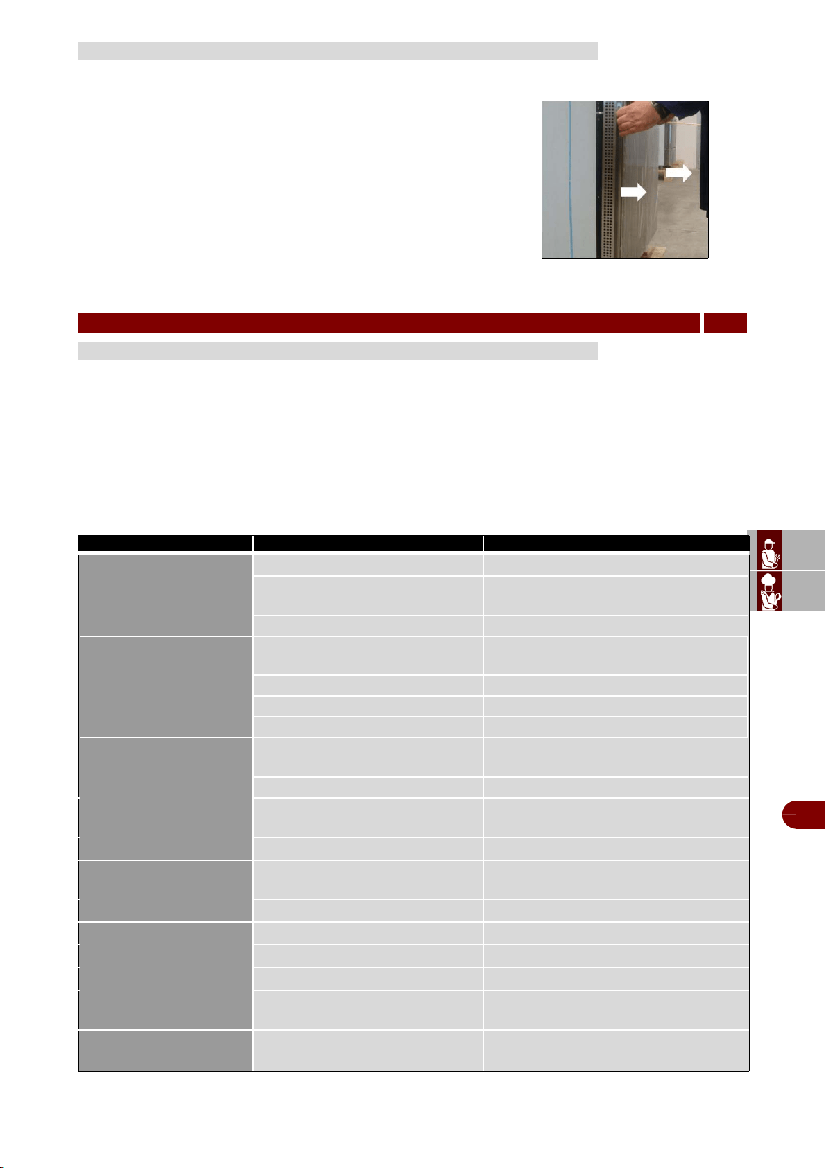
ES
CAN
DE
US
IT
3299702_rev.2.fIDM
Français
-
49
-
Manuel d’utilisation et d’installation
Pour le bon rendement du réfrigérateur, il faut nettoyer soigneusement le
condenseur à air pour permettre à l'air de circuler librement à l'intérieur
de l'appareil.
Les opérations de nettoyage doivent être effectuées tous les 30 jours.
Utilisez une brosse non-métallique pour éliminer la poussière et toutes
substances sales des ailettes du condenseur.
–L'accès au condenseur se fait par l'avant.
–Décrocher la protection de devant en la tirant vers soi et en la tournant
vers la droite.
Avant sa mise en service, l’appareil a été essayé.
Les informations reportées ci-après ont pour but d’aider à l'identification et à la correc-
tion d’éventuels pannes et dysfonctionnements qui pourraient se présenter en cours
d’utilisation.
Certains de ces problèmes peuvent être résolus par l'utilisateur, pour tous les autres
il faut une compétence technique précise ou des capacités particulières; ils doivent
donc être exécutés exclusivement par du personnel qualifié ayant une expérience
reconnue et acquise dans le secteur spécifique d'intervention.
NETTOYAGE DU CONDENSEUR A AIR A
PANNES
6
DÉPANNAGE
Panne Cause Solution
La carte écran ne
s'allume pas
Pas d'alimentation électrique Vérifier le branchement au réseau électrique
Fusible claqué
Remplacer les coupe-circuits (technique
spécialisé)
Connexions desserrées Vérifier le serrage des connexions
Le compresseur ne
fonctionne pas
Pressostat de haute ou basse
pression actionné
Appeler le service technique spécialisé
Clicser actionné Appeler le service technique spécialisé
Le contacteur ne fonctionne pas Appeler le service technique spécialisé
Relais thermique compresseur actionné Appeler le service technique spécialisé
Le compresseur fonc-
tionne mais l'enceinte ne
refroidit pas
Evaporateur plein de givre
Ouvrir la porte et lancer le cycle de dé-
givrage
Pas de liquide réfrigérant Appeler le service technique spécialisé
Electrosoupape de refoulement qui
ne fonctionne pas
Appeler le service technique spécialisé
Le Condenseur est sale
Nettoyer le condenseur
Les ventilateurs de
l'évaporateur ne fonc-
tionnent pas
Détèrioration ou court-circuit des
ventilateurs
Appeler le service technique spécialisé
Micro porte interrompu
Appeler le service technique spécialisé
Les ventilateurs du con-
denseur ne fonctionnent
Pressostat en panne
Appeler le service technique spécialisé
Ventilateur en pann
Appeler le service technique spécialisé
Condenseur de démarrage en panne
Appeler le service technique spécialisé
Non-consentement des télérupteurs
du compresseur
Appeler le service technique spécialisé
Non-dégivrage de
l'évaporateur
Programmation de dégivrage incor-
recte
Vérifiez la programmation du cycle de dé-
givrage
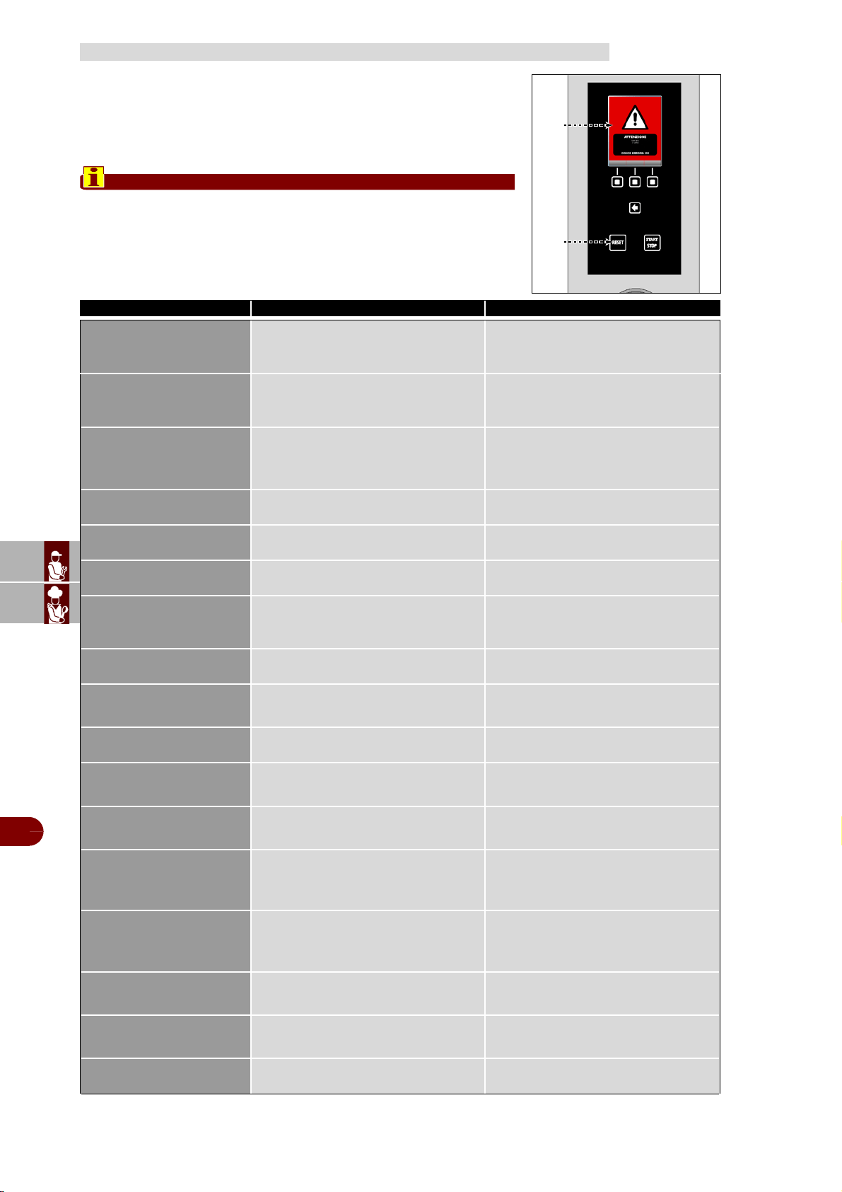
ES
CAN
DE
US
IT
3299702_rev.2.fIDM
Français
-
50
-
Manuel d’utilisation et d’installation
Si le problème ou l'inconvénient relevé ne fait pas partie des pannes
reportées dans le tableau, consulter le tableau "Signalisation des
alarmes" reporté ci-dessous.
Les informations ci-dessous ont pour but d'identifier les signaux
d'alarme qui apparaissent sur les afficheurs (A).
Important
Appuyer sur la touche (D) pour remettre à zérol'alarme.
TABLEAU SIGNALISATIONS DES ALARMES
Alarme / Signal Cause Solution
A01 - Alarme de haute
temperature
(pendant la conservation)
Température cellule supérieure valeur
réglée
Si la température ne rentre pas dans la
normalité, intervention d’un technicien
qualifié
A02 - Alarme de basse
temperature
(pendant la conservation)
Température cellule inférieure à la va-
leur réglée
Si la température ne rentre pas dans la
normalité, intervention d’un technicien
qualifié
A03 - Alarme de tempera-
ture limite
(pendant la réfrigération /
congélation)
Température cellule ou cœur supérieur
à la valeur réglée
Si la température ne rentre pas dans la
normalité, intervention d’un technicien
qualifié
A04 - Alarme sonde cham-
bre
Sonde cellule interrompue Appeler le service technique spécialisé
A05 - Alarme sonde evap-
orateur
Sonde évaporateur interrompue Appeler le service technique spécialisé
A06 - Alarme sonde con-
densateur
Sonde condensateur interrompue Appeler le service technique spécialisé
A07 - Alarme condensa-
teur sale/nettoyer le
condensateur
Condensateur sale Nettoyer le condensateur
A08 - Alarme sonde poin-
teur
Sonde pointeau interrompue Appeler le service technique spécialisé
A09 - Alarme sonde sous-
peau epingle
Sonde sous-cutanée à piquer inter-
rompue
Appeler le service technique spécialisé
A10 - Alarme sonde ex-
terne epingle
Sonde externe à piquer interrompue Appeler le service technique spécialisé
A11 - Alarme sonde
tebleau electrique
Sonde du tableau électrique
interrompue
Appeler le service technique spécialisé
A12 - Alarme surchauffe
tebleau electrique
Température du tableau électrique
supérieur à la valeur réglée
Appeler le service technique spécialisé
A13 - Alarme de porte
ouverte
Porte chambre de réfrigération rapide
ouverte
Micro porte en défaillance
Fermer la porte
Appeler le service technique spécialisé
A14 - Alarme de BlackOut
Pas d'alimentation électrique
Dès que l’alimentation revient, vérifier
la température maximale atteinte dans
la cellule
A15 - Alarme de haute
pression
Intervention du pressostat de tempéra-
ture élevée
Appeler le service technique spécialisé
A16 - Alarme de basse
pression
Intervention du pressostat de faible
température
Appeler le service technique spécialisé
A17 - Alarme surcharge
compresseur
Relais thermique compresseur actionné Appeler le service technique spécialisé
A
D
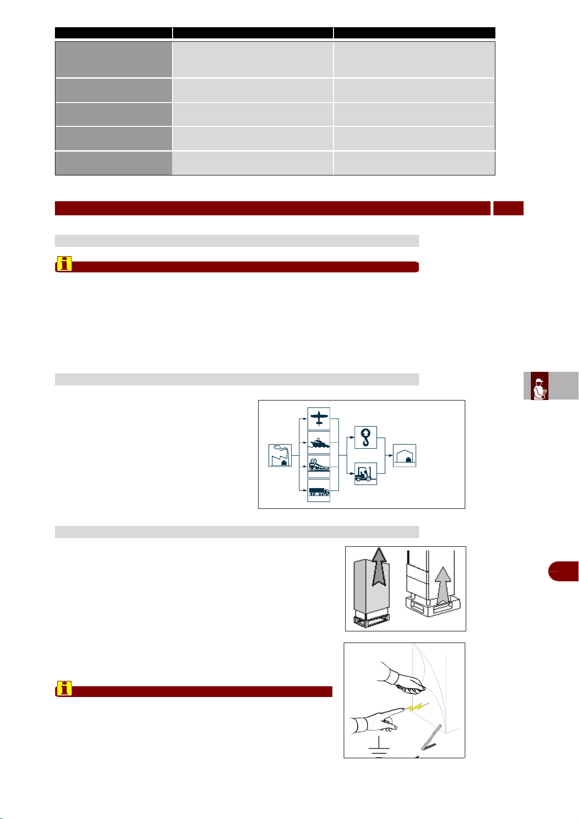
ES
CAN
DE
US
IT
3299702_rev.2.fIDM
Français
-
51
-
Manuel d’utilisation et d’installation
Important
Effectuer la manutention et l’installation en respectant les informations fournies
par le fabricant, reportées directement sur l’emballage, sur l’appareil et dans les
instructions d’utilisation.
Celui qui est autorisé à effectuer ces opérations devra, si nécessaire, organiser
un «plan de sécurité» pour sauvegarder la sécurité des personnes directement
impliquées.
Le transport, en fonction aussi du lieu de des-
tination, peut être effectué avec des moyens
différents.
Le schéma représente les solutions les plus
courantes.
Pendant le transport, afin d’éviter des dé-
placement intempestifs, fixer au moyen de
transport de façon appropriée.
Après avoir retiré l'emballage, s'assurer de l'intégrité de l'appareil
et vérifier que soient présents toutes les pièces ou les com-
posants et que les caractéristiques et l'état correspondent aux
caractéristiques de votre commande.
Si ce nest pas le cas, mettez-vous immédiatement en contact
avec votre revendeur.
Enlevez complètement la pellicule de protection en PVC de l'ap-
parei.
Important
Tous les matériaux de l'emballage doivent être éliminés
selon les normes en vigueur dans le pays d'utilisation de
l'appareil et donc rien ne doit être jeté dans la nature.
A18 - Alarme communica-
tion avec fiche tab-
leau
Communication interrompue entre la
carte du tableau et la carte de l'écran
Appeler le service technique spécialisé
A19 - Alarme EEPROM
fiche display
Mémoire des données endommagée Appeler le service technique spécialisé
A20 - Alarme EEPROM
fiche tableau
Mémoire des données endommagée Appeler le service technique spécialisé
A21 - Alarme sonde coeur
epingle 1
Sonde coeur 1 interrompue Appeler le service technique spécialisé
A22 - Alarme sonde coeur
epingle 2
Sonde coeur 2 interrompue Appeler le service technique spécialisé
MANUTENTION ET INSTALLATION
7
RECOMMANDATIONS POUR LA MANUTENTION ET L’INSTALLATION
TRANSPORT
DÉBALLAGE
Alarme / Signal Cause Solution
dispositifs de levage
moyens de transport
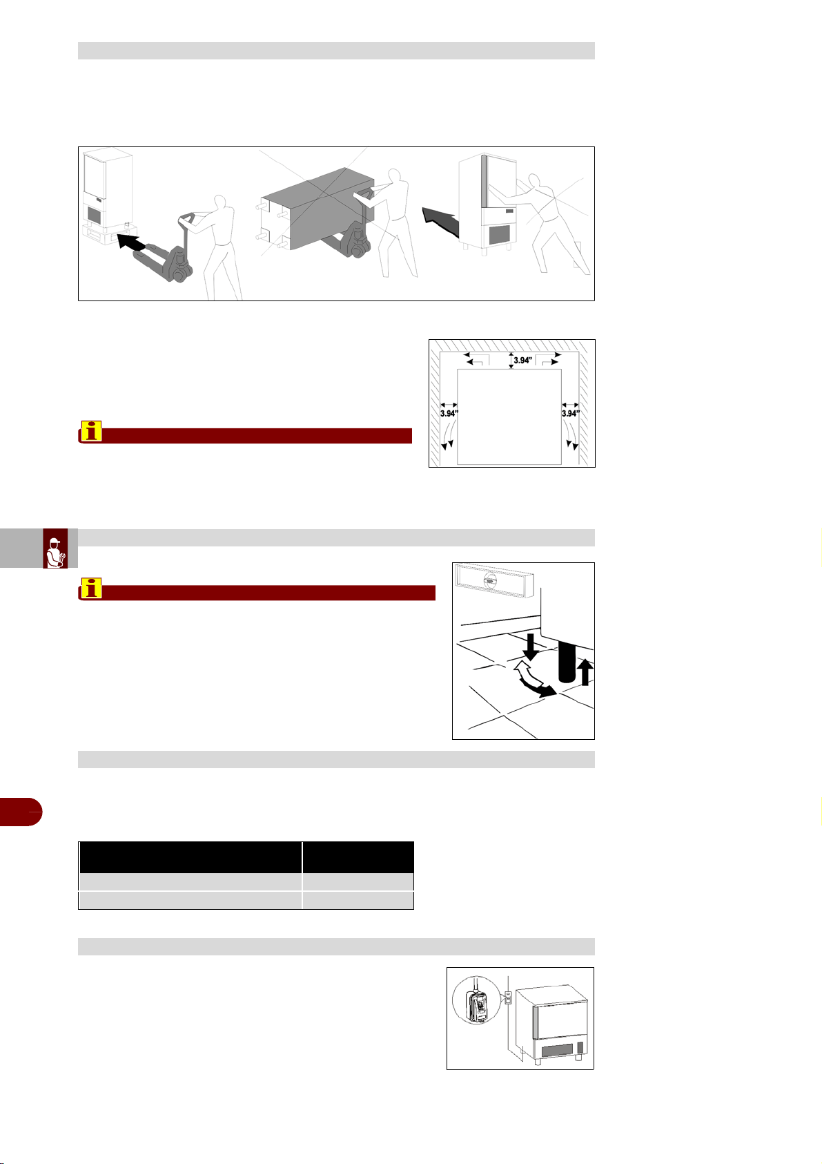
ES
CAN
DE
US
IT
3299702_rev.2.fIDM
Français
-
52
-
Manuel d’utilisation et d’installation
L'appareil doit être installé et les essais effectués en respectant complètement les ex-
igences de sécurité préconisées par la réglementation et les normes nationales.
–Disposez l'appareil à sa place de travail.
–Evitez de placer l'appareil où il pourrait être exposé
aux rayons du soleil.
–Evitez de placer l'appareil à des endroits peu aérés.
–Il faut garder une distance min. de 3.94” entre l’appa-
reil et le mur du local.
Important
L'appareil doit être relié aux fours FX en suivant les
indications de la notice d'instructions jointe au KIT
BE1+FX .
Agir sur les pieds d’appui pour mettre de niveau l’appareil.
Important
Si l'appareil n'est pas mis à niveau correctememt, son
fonctionnement peut être pertubé et l'évacuation de la
condensation empêchée.
Pour les groupes condenseur à air, la température ambiante de fonctionnement ne
doit jamais dépasser les 100°F. Au-dessus de 89°C les rendements déclarès ne sont
pas garantis.
Il est obligatoire d'installer avant l'appareil un interrupteur
omnipolaire selon les normes courantes au pays où l'ap-
pareil est installé.
MISE EN PLACE
MISE À NIVEAU
TEMPERATURE MAX DU LOCAL D’UTILISATIN
Modèle Quantité air
[cfm]
B151MU - B152MU - B151HU 650
B1101SU 2060
BRANCHEMENT ELECTRIQUE

ES
CAN
DE
US
IT
3299702_rev.2.fIDM
Français
-
53
-
Manuel d’utilisation et d’installation
Le branchement électrique se fait dans la partie postérieure
de l'appareil.
Les câbles électriques d'alimentation devront être correcte-
ment dimensionnés et choisis en fonction des conditions
d'installation.
Le conducteur à terre doit être relié correctement à une
installation correcte de mise à la terre.
En cas de non respect de toutes ces dispositions, le con-
structeur décline toute responsabilité et toute obligation
de garantie, en cas de dommages aux appareils, aux per-
sonnes et aux choses et ŕ l’altération de toute partie de
l’appareil (installation éllectrique, thermodynamique,hy-
draulique).
Les appareils sont équipés d'une bassine pour la récupération de la condensation. La
bassine est amovible depuis la partie inférieure de l'appareil.
Si l'appareil a été transporté en position horizontale, IL FAUT ATTENDRE AU MOINS
24 HEURES AVANT LA PREMIERE UTILISATION.
Le fabricant décline toute responsabilité ou toute obligation de garantie pour
des dommages de l'appareil imputables à un transport en position horizontale.
On doit effectuer les essais suivants:
1–Les températures externes doivent être comprises entre 59°F et 100°F.
2–Mettre l’appareil sous tension et attendre 30 minutes avant l’utilisation au cas où
la température externe était trop basse.
3–Vérifier le absorptions
4–Exécuter au moins un cycle complet de réfrigération rapide.
Ces instructions concernent le personnel spécialisé.
Micro interrupteur porte: bloque le fonctionnement de l'appareil quand la porte est
ouverte
Coupe-circuits de protection générale: protègent le circuit de puissance des court-
circuits et des surcharges
Relais thermique compresseur: est actionné en cas de surcharge ou fonctionne-
ment irrégulier
Contact thermique motoventilateur: est actionné en cas de surcharge ou fonction-
nement irrégulier
Pressostat de sécurité: est actionné en cas de surpression du liquide réfrigérant
Contrôle de la température dans l'enceinte: est géré par la sonde NTC par la fiche
électronique appropriée
Contrôle de la température au coeur des produits: est géré par la sonde PT100
par la fiche électronique
Fiches électroniques: en fonction des paramètres insérés, elles commandent et
contrôlent les dispositifs branchés sur l'appareil.
EVACUATION DE CONDENSATION
ESSAIS
SYSTÉMES DE CONTRÔLE ET TÉMOINS

ES
CAN
DE
US
IT
3299702_rev.2.fIDM
Français
-
54
-
Manuel d’utilisation et d’installation
Le kit lampe germicide n’est pas fourni de série.
Si l’on désire acheter le kit, suivre les instructions reportées dans le manuel d’instruc-
tion relatif pour son installation.
L’imprimante n’est pas fournie de série.
Si l’on désire acheter l’imprimante, suivre les instructions reportées dans le manuel
d’instruction relatif pour son installation.
Avant d'effectuer tout remplacement, activer les dispositifs de sécurité prévus et éval-
uer s'il faut informer les opérateurs travaillant sur l'appareil et ceux à proximité. En par-
ticulier fermer le robinet d'alimentation de l'eau, couper l'alimentation électrique à
l'aide de l'interrupteur sectionneur de l'appareil et empêcher l'accès à tous les disposi-
tifs qui pourraient, s'ils sont activés, provoquer des conditions de danger inattendu
pour la sécurité et la santé des personnes.
S'il faut remplacer des composants usés, utiliser exclusivement des pièces de re-
change d'origine.
Le fabricant décline toute responsabilité pour des dommages à des personnes ou à
des composants dérivant de l'utilisation de pièces de rechange qui ne sont pas d'orig-
ine et d'interventions extraordinaires qui peuvent modifier les conditions requises de
sécurité, sans son autorisation.
Pour la demande de composants, suivre les indications reportées dans le catalogue
des pièces de rechange.
Au moment de l’élimination, il faut effectuer une série d’opérations pour faire en sorte
que l'appareil et ses composants ne constituent pas une gêne et ne soient pas facile-
ment accessibles.
Pour éviter que l'appareil puisse constituer un danger pour les personnes et l’environ-
nement, il faut débrancher et rendre inutilisables toutes les sources d’alimentation
(électrique, etc.) et vider tous les liquides éventuellement présents (lubrifiants, huiles,
etc.).
Déposer l'appareil dans une zone adaptée, qui n’est pas facilement accessible et qui
est opportunément délimitée pour éviter son accès à quiconque.
Lors de la démolition, sélectionner tous les composants en fonction de leurs cara-
ctéristiques chimiques et effectuer la collecte différenciée en respectant les lois en
vigueur en la matière.
Important
Cette opération doit être effectuée par des opérateurs experts, dans le respect
des lois en vigueur sur la sécurité du lieu de travail. Ne pas disperser dans l’at-
mosphère des produits non biodégradables, huiles lubrifiantes et composants
non ferreux (caoutchouc, PVC, résines, etc.). Les éliminer en respectant les lois
en vigueur.
INSTALLATION DU KIT LAMPE GERMICIDE
INSTALLATION DE L’IMPRIMANTE
REMPLACEMENT DE PIÈCES
8
RECOMMANDATIONS POUR LE REMPLACEMENT DES PIÈCES
ÉLIMINATION DE L'APPAREIL

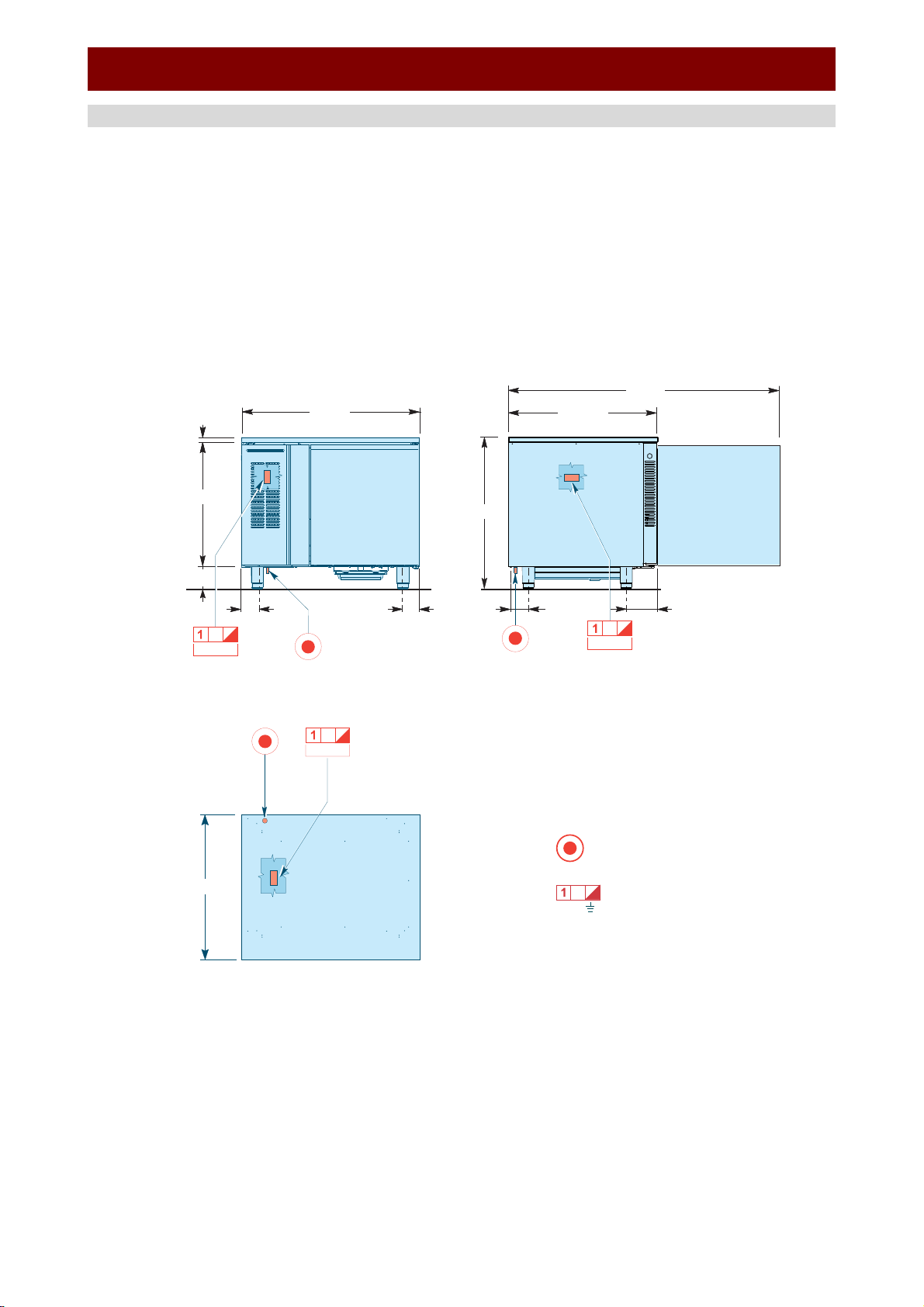
ES
FR
DE
GB
IT
CT3299702_rev.
-
I
-
ANNEXES - ANNEXES
CONNECTION DIAGRAM B151HU - CARTE RACCORDEMENTS B151HU
Terminal board
Plaque à bornes
1~ N
220 V
Electric connection
Branchement electrique
1,122 kW
4,09
”
6,41
”
50,98
”
33,07
”
36,57
”
25,59
”
30,67
”
(6,5
”)*
3,28”
3,28
”
1,122 kW
1,122 kW
30,67
”
0,98”
* Feet height-adjustable from 4,5” to 6,5”
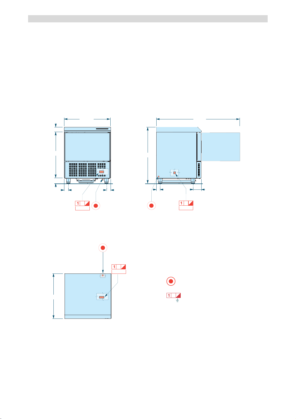
ES
FR
DE
GB
IT
CT3299702_rev.
-
II
-
CONNECTION DIAGRAM B151MU - CARTE RACCORDEMENTS B151MU
28,38”
29,13”
2,22”
2,22”
2,43”
5”
38,19”
1,139 kW
1,139 kW
1,139 kW
3,15”
29,38”
55,39”
(5,9”)*
Terminal board
Plaque à bornes
1~ N
220 V
Electric connection
Branchement electrique
* Feet height-adjustable from 5,9” to 7,9”
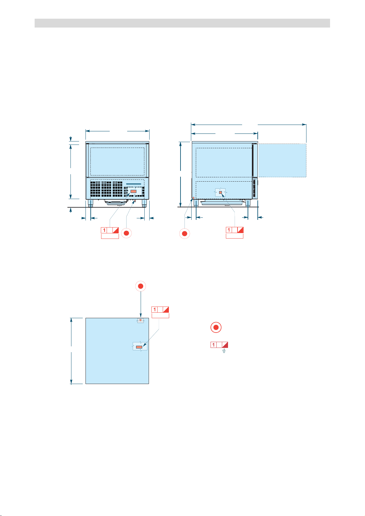
ES
FR
DE
GB
IT
CT3299702_rev.
-
III
-
CONNECTION DIAGRAM B152MU - CARTE RACCORDEMENTS B152MU
37,28”
30,32”
0,98”
2,62” 2,62”
(5,9”)*
5,2”
2,42”
67,44”
34,29”
35,51
35,51”
1,52 kW
1,52 kW
1,52 kW
Terminal board
Plaque à bornes
1~ N
220 V
Electric connection
Branchement electrique
* Feet height-adjustable from 5,9” to 7,9”
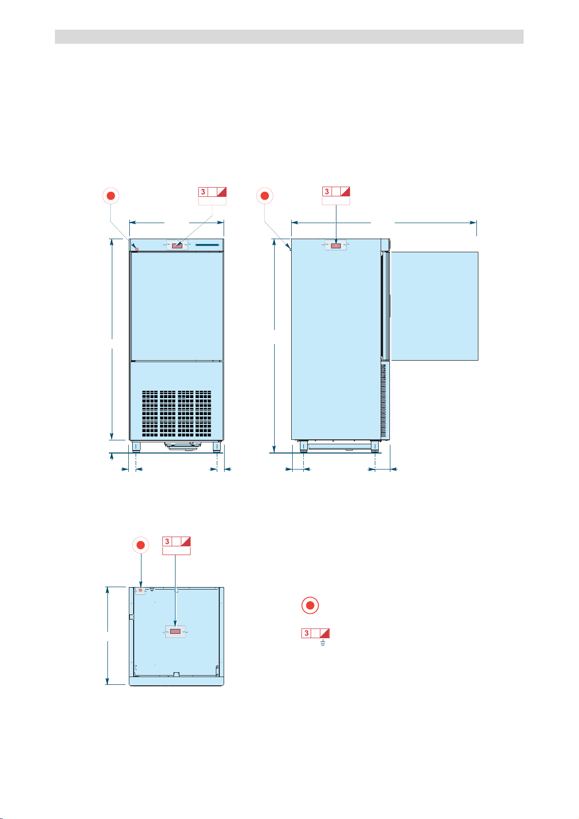
ES
FR
DE
GB
IT
CT3299702_rev.
-
IV
-
CONNECTION DIAGRAM B1101SU - CARTE RACCORDEMENTS B1101SU
32,68”
67,33”
(5,9”)*
2,36”
2,36”
4,15”
4,93”
61,61”
73,23”
31,49”
2,625kW2,625 kW
2,625 kW
Terminal board
Plaque à bornes
Electric connection
Branchement electrique
* Feet height-adjustable from 5,9” to 7,9”
3~ N
220 V

ES
FR
DE
GB
IT
CT3299702_rev.
-
V
-
ELECTRICAL SYSTEM DIAGRAM B151HU - SCHEMA ELECTRIQUE B151HU
M
1
1
1
1
2
2
4
4
3
3
A
2
M
5
5
6
6
1 2 3 4
1234
86
H P
70
1
2A
M
B
1 2 3 4
1234
C
1
9
M
23
3
21
1
1
1 2 3 4
1234
78
77
E
75
1
4
42
5
5
21NL1
73
N
L1
1234
56 78
CN18
CN19
CN11
CN10
CN13
CN12
CN5
CN4
CN9
MCU
BATT1
12 11 10 9
16 15 14 1320 19 18 1723 22 2125 24
12 11 10 9 87
654
3
12
Load 1
Power in
Power in Alarm Comp. Evap.
fan
Defr. Cond..
fan
Door
heater
Clean
room
N
CN5
CN4
CN1
CN7
Load 2
CN6
67
12V230V
25
71
97A
69
102
6
6
L1
D
3290860
33
22
11
M
1
2
1
2
T
blue
black
brown
CN2
CN2
CN3
CN3
CN7
CN6 CN8
Probe
heater
1
1
2
2
R
1 2
12
N
3
3
to signal printer
to LUV
1 2
12
3
3
S
to power printer
NC
LC
LOAD LOAD
56
65
A1 A2
L2C
T2C
L1C
T1C
L3C
T3C
2
1
11
14
12
21
24
22
44
1
1
2
2
4
4
3
3
G
5
5
6
6
79A
79B
20
1 2
12
H
1
1
2
2
4
4
3
3
I
1 2
12
F
76
12 3
122
blue
red
green
black
3
3
CN4
CN1
CN2
567843
21
CN3
CN5
blue
red
green
black
130
21
12
O
CN3
CN1
CN2
128
AWG18
AWG14
AWG14
AWG18
AWG18
AWG18
AWG18
AWG18
AWG18
AWG16
AWG18 AWG18
AWG18
AWG18
AWG16
AWG14
AWG14
AWG16
AWG14
AWG14
AWG14
AWG14
AWG14
AWG14
AWG18
AWG16
AWG16
0.35 mmq
AWG16
AWG16
AWG16
AWG16
AWG16
AWG16
AWG16
AWG16
0.35 mmq
0.35 mmq
0.35 mmq
0.35 mmq
0.35 mmq
0.35 mmq
0.35 mmq
0.35 mmq
0.35 mmq
0.35 mmq
0.35 mmq
AWG16
AWG16
AWG14
AWG16
AWG16
AWG16
AWG16
AWG16
AWG16
AWG16
AWG16
AWG18
0.35 mmq
0.35 mmq
0.35 mmq
AWG16
AWG16
AWG16
AWG16
AWG16
AWG16
AWG18
AWG16
AWG18
AWG16
AWG18
0.35 mmq
0.35 mmq
0.35 mmq
0.35 mmq
0.35 mmq
0.35 mmq
0.35 mmq
AWG16
0.35 mmq
0.35 mmq
0.35 mmq
0.35 mmq
0.35 mmq
AWG14
AWG16
AWG16
AWG18
AWG16
AWG18
AWG18
AWG18
AWG18
AWG18
AWG18
AWG14
AWG14
AWG14
AWG18
AWG18
AWG18
AWG18
AWG16
AWG16
AWG16
AWG20
AWG20
AWG20
AWG20
AWG24
AWG24
AWG26
AWG26
AWG26
AWG26
AWG26
AWG26
AWG26
0.35 mmq
0.25 mmq
0.25 mmq
0.25 mmq
0.25 mmq
0.25 mmq
0.25 mmq
AWG18
AWG18
AWG18
2
3
3
1 1
4 4
2
5 5
6 6
L
1
2
1
2
TO OVEN
DISPLAY
RAST
JUNCTION
0.35 mmq
0.35 mmq
0.35 mmq
131
31 24
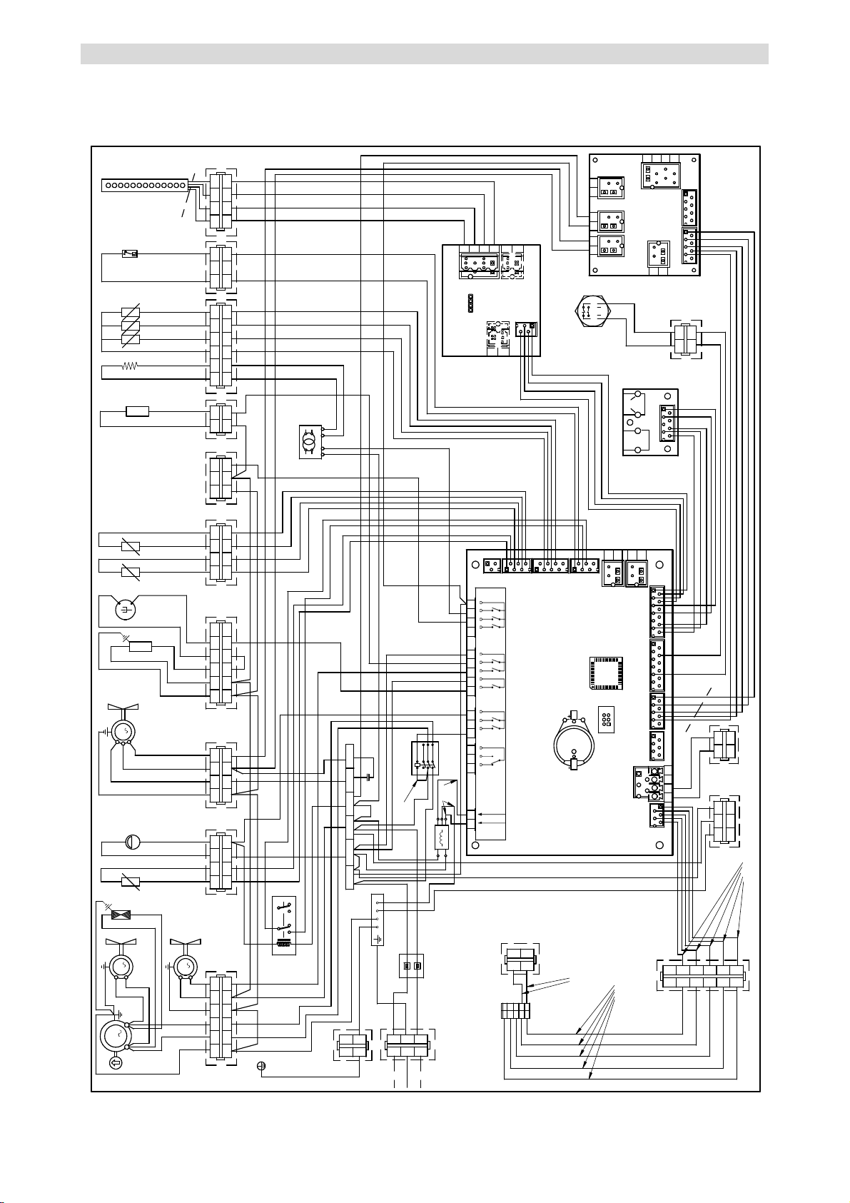
ES
FR
DE
GB
IT
CT3299702_rev.
-
VI
-
ELECTRICAL SYSTEM DIAGRAM B151MU - SCHEMA ELECTRIQUE B151MU
M
1
1
1
1
2
2
4
4
3
3
A
2
M
5
5
6
6
1 2 3 4
1234
86
H P
70
1
2A
M
B
1 2 3 4
1234
C
1
9
M
23
3
21
1
1
1 2 3 4
1234
78
77
E
1
1
2
2
4
4
3
3
G
5
5
6
6
79A
75
1
79B
4
42
5
5
20
1 2
12
H
21NL1
65
73
N
L1
A1
L2C
T3C
L1C
T2C
1234
56 78
CN18
CN19
CN11
CN10 CN13
CN12
CN5
CN4
CN9
MCU
BATT1
12 11 10 9
16 15 14 1320 19 18 1723 22 2125 24
12 11 10 9 87
654
3
12
Load 1
Power in
Power in Alarm Comp. Evap.
fan
Defr. Cond..
fan
Door
heater
Clean
room
N
CN5
CN4
CN1
CN7
Load 2
CN6
67
12V230V
25
71
97A
69
1
1
2
2
4
4
3
3
I
1 2
12
F
102
76
12 3
CN4
CN1
CN2
567843
21
CN3
CN5
122
6
6
L1
D
2
3
3
1 1
4 4
2
5 5
6 6
L
3285200
33
22
11
M
1
2
1
2
T
blue
black
brown
blue
red
green
black
blue
red
green
black
3
3
CN2
CN2
CN3
CN3
CN7
CN6 CN8
Probe
heater
1
1
2
2
R
1 2
12
N
3
3
to signal printer
to LUV
130
1 2
12
3
3
S
to power printer
NC
LC
LOAD LOAD
56
A2
L3C
T1C
131
21
12
O
31 24
1
2
1
2
TO OVEN
DISPLAY
RAST
JUNCTION
2
1
11
14
12
21
24
22
44
CN3
CN1
CN2
128
AWG18
AWG14
AWG14
AWG18
AWG16
AWG16
AWG14
AWG14
AWG16
AWG14
AWG14
AWG14
AWG16
AWG14
AWG16
AWG16
AWG14
AWG14
AWG14
AWG18
AWG18
AWG18
AWG16
AWG14
AWG14
AWG16
AWG16
AWG18
AWG18
AWG16
AWG16
AWG16
AWG16
AWG18
AWG16
0.35 mmq
0.35 mmq
0.35 mmq
AWG16
AWG16
AWG16
AWG16
AWG16
AWG16
AWG16
AWG16
AWG16
AWG16
AWG16
AWG16
AWG16
AWG16
AWG14
AWG18
AWG18
AWG18
AWG18
AWG18
AWG18
AWG18
AWG18
AWG16
AWG16
AWG16
AWG16
AWG16
0.35 mmq
0.35 mmq
0.35 mmq
0.35 mmq
0.35 mmq
0.35 mmq
0.35 mmq
0.35 mmq
0.35 mmq
0.35 mmq
0.35 mmq
0.35 mmq
0.35 mmq
0.35 mmq
0.35 mmq
0.35 mmq
0.35 mmq
0.35 mmq
0.35 mmq
0.35 mmq
0.35 mmq
0.35 mmq
0.35 mmq
0.35 mmq
0.35 mmq
0.35 mmq
0.35 mmq
0.35 mmq
AWG16
AWG16
AWG18
AWG18
AWG18
AWG18
AWG18
AWG18
AWG14
AWG14
AWG14
AWG18
AWG18
AWG18
AWG18
AWG16
AWG16
AWG16
AWG20
AWG20
AWG20
AWG20
AWG24
AWG24
AWG26
AWG26
AWG26
AWG26
AWG26
AWG26
AWG26
0.35 mmq
0.25 mmq
0.25 mmq
0.25 mmq
0.25 mmq
0.25 mmq
0.25 mmq
AWG18
AWG18
AWG18
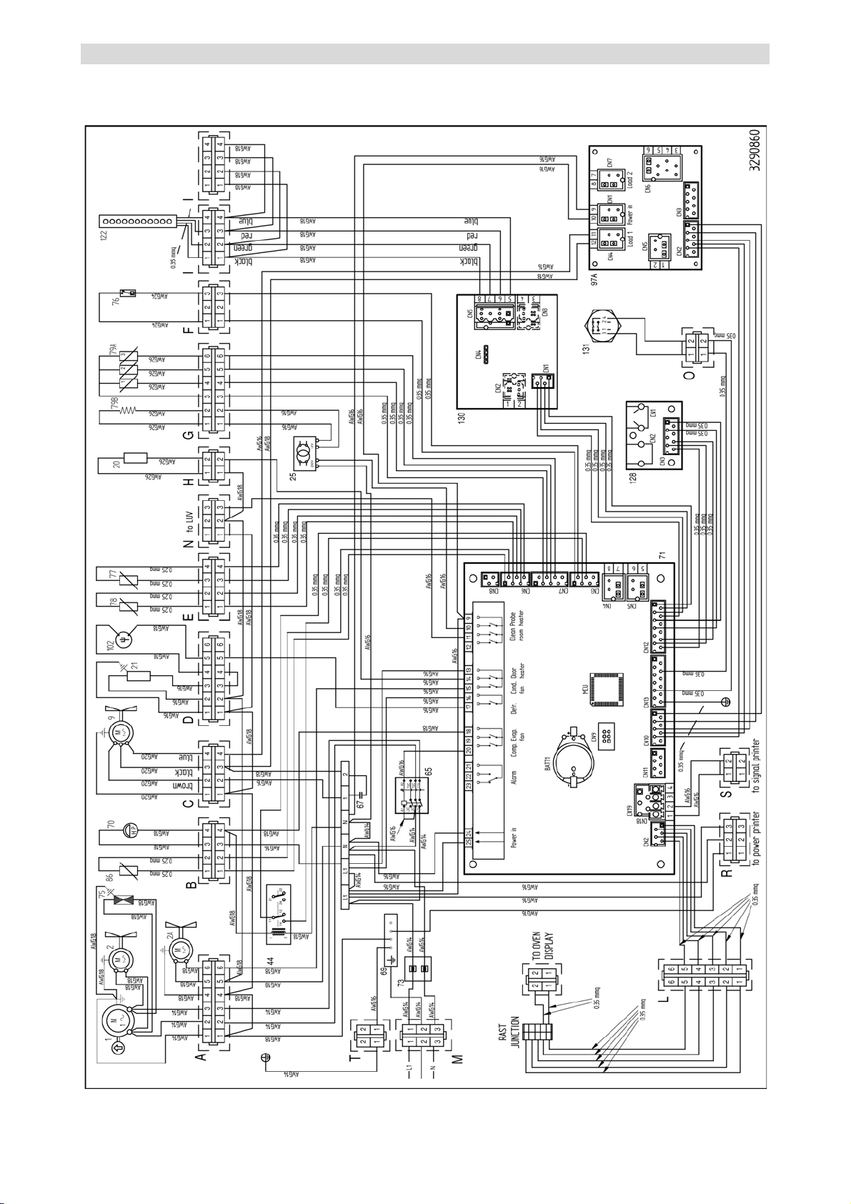
ES
FR
DE
GB
IT
CT3299702_rev.
-
VII
-
ELECTRICAL SYSTEM DIAGRAM B152MU - SCHEMA ELECTRIQUE B152MU
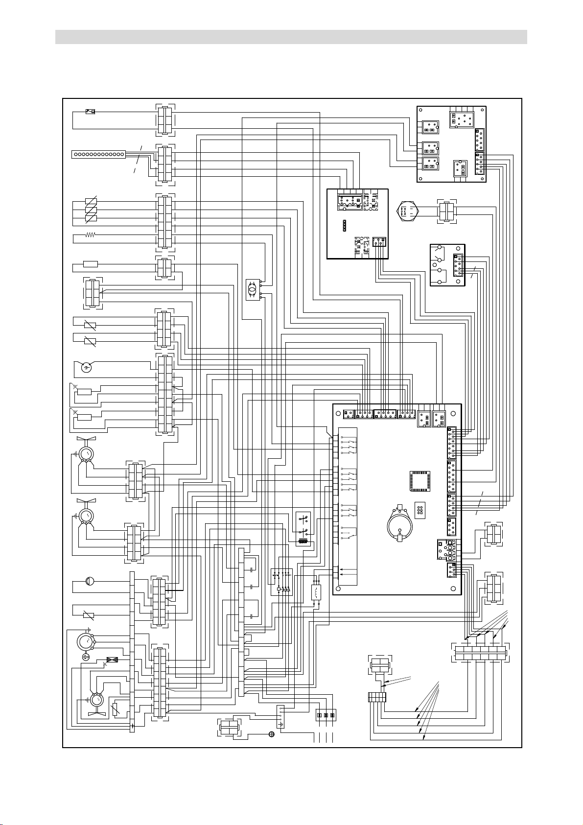
ES
FR
DE
GB
IT
CT3299702_rev.
-
VIII
-
ELECTRICAL SYSTEM DIAGRAM B1101SU - SCHEMA ELECTRIQUE B1101SU
1
1
2
2
4
4
3
3
I
122
blue
red
green
black
CN4
CN1
CN2
567843
21
CN3
CN5
130
blue
red
green
black
1 2 3 4
1234
78
77
20
1 2
12
43NL3 2
67
69
73
L1
L2
L3
L2L1
65+66
A1 96
L1C
L2C
L3C T3C
T2C
T1C
A2 95
9897
5
67A
1N
87
3
3290870
1
2
1
2
1
1
2
2
4
4
3
3
G
5
5
6
6
79A
79B
1234
56 78
CN18
CN19
CN11
CN10 CN13
CN12
CN5
CN4
CN9
MCU
BATT1
12 11 10 9
16 15 14 1320 19 18 1723 22 2125 24
12 11 10 9 87
654
3
12
Load 1
Power in
Power in Alarm Comp. Evap.
fan
Defr. Cond..
fan
Door
heater
Clean
room
CN5
CN4
CN1
CN7
Load 2
CN6
12V230V
25
71
97A
1 2
12
F
76
123
2
3
3
1 1
4 4
2
5 5
6 6
L
3
3
CN2
CN2
CN3
CN3
CN7
CN6 CN8
Probe
heater
CN3
CN1
CN2
1
1
2
2
R
1 2
12
3
3
to signal printer
128
S
to power printer
to LUV
1 2
12
3
3
NC
LC
LOAD LOAD
56
220÷240 V 3F 50/60 Hz
2
1
11
14
12
21
24
22
44
1 2 3 4
1234
C
1
9
M
blue
black
brown
1 2 3 4
1234
C1
1
9A
M
blue
black
brown
21
1 2 3 5
123 5
76
67
4
4
8
8
9
9
21A
102
21
12
O
1 2 3 4
1234
86
H P
70
M
3
1
FvNL1
Fc2Fc1
AUX
Fc3
1
2
M
80
75
1
1
2
2
4
4
3
3
5
5
6
6
7
7
8
8
3A
9
9
5 6
56
brown
blue
black
Sc1 Sc2 HP1 HP2
AWG18
AWG16
AWG18
AWG18
AWG18
AWG18
AWG18
AWG18
AWG18
AWG18
AWG16
AWG18
AWG16
AWG18
AWG18
AWG18
AWG14
AWG18
AWG18
AWG16
AWG14
AWG16
AWG16
AWG16
AWG18
AWG16
AWG14
AWG14
AWG14
AWG16
AWG16
AWG16
AWG18
AWG18
AWG16
AWG16
AWG18
AWG14
AWG14
AWG14
AWG14
AWG14
AWG16
AWG14
AWG16
AWG16
0.35 mmq
0.35 mmq
0.35 mmq
AWG16
AWG16
AWG16
0.35 mmq
AWG16
AWG16
0.35 mmq
0.35 mmq
0.35 mmq
0.35 mmq
0.35 mmq
0.35 mmq
0.35 mmq
AWG16
AWG16
AWG16
AWG16
AWG16
AWG16
AWG16
AWG16
0.35 mmq
0.35 mmq
0.35 mmq
0.35 mmq
0.35 mmq
0.35 mmq
0.35 mmq
0.35 mmq
0.35 mmq
0.35 mmq
0.35 mmq
0.35 mmq
AWG16
AWG16
AWG18
AWG18
AWG18
AWG18
0.35 mmq
0.35 mmq
0.35 mmq
0.35 mmq
0.35 mmq
0.35 mmq
AWG16
0.35 mmq
0.35 mmq
AWG16
AWG14
AWG14
AWG16
AWG16
AWG16
AWG14
AWG18
AWG24
AWG24
AWG26
AWG26
AWG26
AWG26
AWG26
AWG26
AWG26
0.35 mmq
AWG18
AWG18
AWG16
AWG16
AWG16
AWG16
AWG16
AWG16
AWG20
AWG20
AWG20
AWG20
AWG20
AWG20
AWG20
AWG20
0.25 mmq
0.25 mmq
0.25 mmq
0.25 mmq
0.25 mmq
0.25 mmq
AWG18
AWG18
AWG14
AWG14
AWG14
AWG14
AWG18
AWG20
AWG20
AWG20
AWG18
AWG20
AWG18
AWG14
AWG14
1
2
1
2
TO OVEN
DISPLAY
RAST
JUNCTION
0.35 mmq
0.35 mmq
131
31 24

Angelo Po America
427 Sargon WAY
SUITE “E”
Horsham, Pennsylvania 19044
Tel: 215-323-4917
Fax: 267-803-6975
www.angelopoamerica.com