
Loading ...
Loading ...
Loading ...
ENGLISH
6
SHOCKS® Active Vibration Control
System
For best vibration control, hold the tool as described in
Proper Hand Position and apply just enough pressure so
the damping device on the main handle is approximately
mid stroke. The hammer only needs enough pressure to
engage the active vibration control. Applying too much
pressure will not make the tool chip faster and active
vibration control will notengage.
DeWALT
Tool Tag Ready (Fig. A)
Optional Accessory
Your hammer comes with mounting holes
10
and
fasteners for installing a
DeWALT
Tool Tag. You will need a
T15 bit tip to install the tag. Only use the screws provided.
The
DeWALT
Tool Tag is designed for tracking and locating
professional power tools, equipment, and machines using
the
DeWALT
Tool Connect™ app. For proper installation
and use of the
DeWALT
Tool Tag refer to the
DeWALT
Tool
Tagmanual.
Electronic Speed and Impact Control
(Fig.A)
The electronic speed and impact control allows the use of
smaller chisels without the risk of chisel breakage, chipping
into light and brittle materials without shattering and
optimal tool control for precisechiseling.
To set the speed dial
8
, turn the dial to the desired level.
The higher the number, the greater the speed and impact
energy. Dial settings make the tool extremely flexible and
adaptable for many different appli cations. The required
setting depends on the chisel size and hardness of material
beingchipped.
Service Indicator LEDs (Fig.A)
Your chipping hammer has two service indicator LEDs
9
.
Refer to the table for more information on LEDfunctionality.
LED Function Description
Red
(flashing)
Service
The red indicator LED
9
lights
up if there is a fault with the tool
or the brushes have completely
worn out.
Yellow
(permanently on)
Brush Service
The yellow brushwear indicator
LED
9
lights up when the carbon
brushes are nearly worn out,
indicating that the tool needs
servicing within the next 8 hours
ofuse.
Mode Selection (Fig.E)
WARNING: Do not select the operating mode when
the tool isrunning. Tool must come to a complete stop
before activating the mode selector button or damage
to the tool mayresult.
Your tool is equipped with a mode selector dial
4
to
selectthe mode appropriate to desiredoperation.
Symbol Mode Application
Chisel
Adjustment
Chisel position
adjustment
Chipping
Light chipping, chiseling
and demolition
To Select a Mode
• Rotate the mode selector dial
4
so that the
arrow points to the symbol corresponding for the
desiredmode.
Fig. E
4
NOTE: The arrow on the mode selector dial
4
must be
pointing at a mode symbol at all times. There are no
operable positions inbetween.
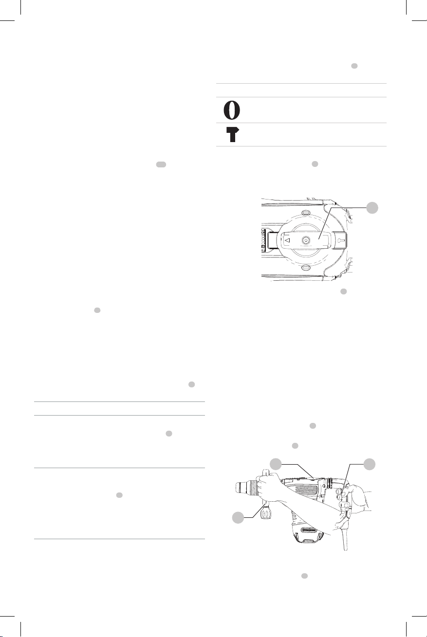
Performing an Application (Fig.F)
WARNING: TO REDUCE THE RISK OF PERSONAL
INJURY, ALWAYS ensure workpiece is anchored or
clampedfirmly.
NOTE: Operating temperature of this tool is 19˚F to 104˚F
(-7˚C to +40˚C). Using the tool outside of this temperature
range will decrease the life of thetool.
1. Insert the appropriate chisel and rotate it by hand to
lock it into the desired position. Refer to Chisel and
ChiselHolder.
2. Using the mode selector dial
4
, selectchipping mode .
Refer to ModeSelection.
3. Adjust the side handle
2
asnecessary.
Fig. F
2
4
1
4. Place the chisel on the desiredlocation.
5. Depress the rocker switch
1
.
6. To stop the hammer, release theswitch.
Loading ...
Loading ...
Loading ...