
Loading ...
Loading ...
Loading ...
11
ASSEMBLY
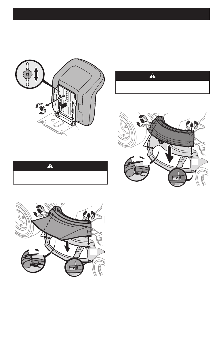
Seat Adjustment
1. To adjust the position of the seat, remove the adjustment
knob on the bottom of the seat. Slide the seat forward or
backward as desired. Reinstall the adjustment knob. Refer
to Figure 10.
Figure 10
Installing the Deck Chute
WARNING
Never operate this riding mower without either the
mulch plug or deck chute installed.
1. Remove the wing knobs (a) installed on the mowing deck and
retain for later installation. See Figure 11.
(a)
(a)
(b)
(c)
(c)
(d)
(e)
(f)
(g)
Figure 11
2. Install the deck chute (b) into the deck discharge opening
on the deck. The rear of the chute (b) should be under the
tab (f) on the rear deck bracket (g). The studs (c) on the deck
surface will fit through the holes on the upper portion of the
deck chute (b). The small tab (d) on the deck lip area will fit
through the square cutout on the lower portion of the deck
chute (b). See Figure 11.
NOTE: Make certain that the upper-rear portion of deck chute (b)
is depressing the safety switch (e) located on the deck surface
and under the tab (f) on the rear deck bracket (g). The engine will
not start without the deck chute (b) properly in place.
3. Secure the deck chute (b) by tightening the wing knobs (a)
removed in Step 1. See Figure 11.
Installing the Mulch Plug (If equipped)
WARNING
Never operate this riding mower without either the
mulch plug or deck chute installed.
1. Remove the wing knobs (a) installed on the mowing deck and
retain for later installation. See Figure 12.
(a)
(a)
(b)
(c)
(c)
(d)
(e)
(f)
(g)
Figure 12
2. Install the mulch plug (b) into the deck discharge opening on
the deck. The rear of the mulch plug (b) should be under the
tab (f) on the rear deck bracket (g). The studs (c) on the deck
surface will fit through the holes on the upper portion of the
mulch plug (b). The small tab (d) on the deck lip area will fit
through the square cutout on the lower portion of the mulch
plug (b). See Figure 12.
NOTE: Make certain that the upper-rear portion of mulch plug
(b) is depressing the safety switch (e) located on the deck surface
and under the tab (f) on the rear deck bracket (g). The engine will
not start without the mulch plug (b) properly in place.
3. Secure the mulch plug (b) by tightening the wing knobs (a)
removed in Step 1.
Loading ...
Loading ...
Loading ...