
Loading ...
Loading ...
Loading ...
English
9
CAUTION: Do not tighten the adjusting screw with
the guard latch in the open position. Undetectable
damage to the guard or the mounting hub may result.
CAUTION: If the guard cannot be tightened by the
adjusting clamp, do not use the tool. To reduce the risk
of personal injury, take the tool and guard to a service
center to repair or replace the guard.
nOTE: Edge grinding and cutting can be performed with
Type 27 wheels designed and specified for this purpose;
1/4" (6.35 mm) thick wheels are designed for surface
grinding while 1/8" (3.17 mm) wheels are designed for edge
grinding. Cutting can also be performed by using a Type 1
wheel and a Type 1 guard.
OPERATION
WARNING: To reduce the risk of serious personal
injury, turn unit off and disconnect it from
power source before making any adjustments or
removing/installing attachments or accessories.
An accidental start-up can causeinjury.
Proper Hand Position
WARNING: To reduce the risk of serious personal injury,
ALWAYS use proper hand position as shown.
WARNING: To reduce the risk of serious personal injury,
ALWAYS hold securely in anticipation of a sudden
reaction.
Proper hand position requires one hand on the side
handle
8
, with the other hand on the body of the tool.
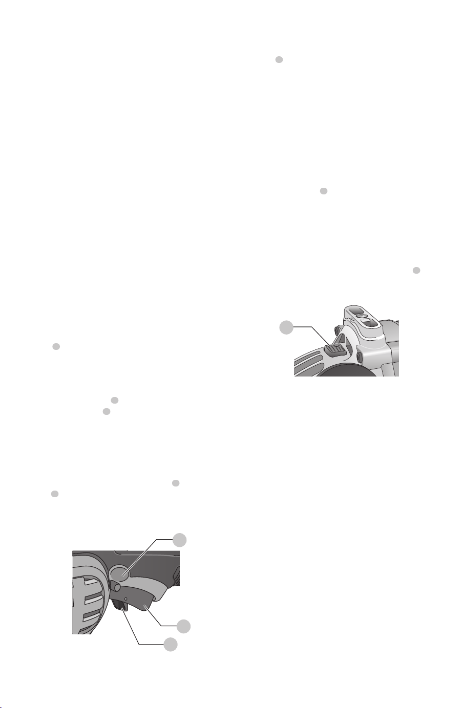
Switch (Fig. H)
CAUTION: Before connecting the tool to a power
source or after a power failure, depress and release
the trigger switch
1
once without depressing the
lock-on button
3
to ensure that the switch is in the off
position. If the trigger switch is locked on, the tool will
start unexpectedly when power is reconnected to the
tool. Hold the side handle and rear handle firmly to
maintain control of tool at start up and during use.
Trigger Operation
To turn the tool on, depress lock-off button
2
then trigger
switch
1
. The trigger can be feathered as long as the
lock-off button is depressed. The tool will remain running
while the trigger is depressed. Turn the tool off by releasing
thetrigger.
Fig. H
3
1
2
Trigger Operation with Lock-On Feature
To turn tool on, depress trigger. Depress and hold lock-
on button
3
while releasing trigger. Lock-on button will
remain depressed and tool will remain on.
To turn the tool off, depress and release trigger. The lock-on
button will pop out, permitting the trigger to disengage and
causing the tool to turn off.
nOTE: Allow the tool to reach full speed before touching
tool to work surface. Lift the tool from the work surface
before turning the tool off.
CAUTION: Make sure the wheel has come to a
complete stop be fore setting the tool down.
Spindle Lock Button (Fig. I)
The spindle lock button
4
is provided to prevent the
spindle from rotating when installing or removing wheels.
NOTICE: To reduce the risk of damage to the tool,
do not engage the spindle lock button while the
tool is operating. Damage to the tool will result and
attached accessory may spin off possibly resulting
ininjury.
To engage the lock, depress the spindle lock button
4
and rotate the spindle until you are unable to rotate the
spindlefurther.
Fig. I
4
Mounting and Using Depressed Center
Grinding Wheels and Sanding Flap Discs
Mounting and Removing Hubbed
Wheels
Hubbed wheels install directly on the 5/8”—11
threadedspindle.
1. Thread the wheel on the spindle by hand, seating the
wheel against the soft mount.
2. Depress the spindle lock button and use a wrench to
tighten the hub of the wheel.
3. Reverse the above procedure to remove the wheel.
CAUTION: Failure to properly seat the wheel against
the soft mount before turning the tool on may result in
damage to the tool or the wheel.
Mounting Non-Hubbed Wheels
Depressed center, Type 27 grinding wheels must be used
with available accessory flanges. Refer to the Accessories
Chart for more information.
Loading ...
Loading ...
Loading ...