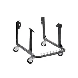
750 LBS ENGINE STAND
USER MANUAL
We continue to be committed to provide you tools with competitive price.
"Save Half", "Half Price" or any other similar expressions used by us only represents an
estimate of savings you might benefit from buying certain tools with us compared to the major
top brands and doses not necessarily mean to cover all categories of tools offered by us. You
are kindly reminded to verify carefully when you are placing an order with us if you are
actually saving half in comparison with the top major brands.


- 1 -
Have product questions? Need technical support? Please feel free to
contact us:
CustomerService@vevor.com
NEED HELP? CONTACT US!
This is the original instruction, please read all manual instructions
carefully before operating. VEVOR reserves a clear interpretation of our
user manual. The appearance of the product shall be subject to the
product you received. Please forgive us that we won't inform you again if
there are any technology or software updates on our product.
750 LBS ENGINE STAND

- 2 -
SPECIFICATION
ITEM
CAPACITY
N.W(kg)
G.W.(kg)
XXJD15001000
750
18.8
20.9
INSPECTION
Inspect the equipment carefully before each use. Ensure the
equipment is not damaged, excessively worn, or missing parts.
Do not use the equipment unless it is properly lubricated.
Using equipment that is not in good clean working condition or properly
lubricated may cause serious injury.
Inspect the work area before each use. Make sure it is free and clear of
any potential hazards.
DO NOT OPERATE OR REPAIR THIS EQUIPMENT WITHOUT READING
THIS MANUAL.
To maintain the equipment and user safety, the responsibility of the
owner is to read and follow these instructions.
Inspect the equipment for proper operation and function.
Keep instructions readily available for equipment operators.
Make certain all equipment operators are properly trained; understand
how to safely and correctly operate the unit.
Allow unit operation only with all parts in place and operating properly.
Use only genuine replacement parts.
Service and maintain the unit only with authorized or approved
replacement parts; negligence will make the equipment unsafe for
use and void the warranty.
Carefully inspect the unit on a regular basis and perform all maintenance
as required.
Store these instructions in the handle of your equipment.
Keep all decals on the unit clean and visible.

- 3 -
WARNING!
1. Study, understand, and follow all instructions before operating this
device.
2. Do not exceed rated capacity.
3. Use only on hard, level surfaces, with less than 3 degrees of slope.
4. Center load on mounting plate.
5. Mount and support only on areas of the engine as specified by the
vehicle manufacturer.
6. Lock mounting plate rotating mechanism before applying a load.
7. Lock the wheels/casters before working on the engine.
8. Rotate the engine using the handle or device provided.
9. Assure load is centered and secured to mounting attachments.
10. Off-center loads may make the load and handle rotate in either
direction when the rotational locking device is released.
11. Release rotational locking devices slowly and carefully.
12. No alterations shall be made to this product.
13. Only attachments and/or adapters supplied by the manufacturer shall
be used.
14. Never work directly under a supported load.
15. Do not use this product for any use other than the manufacturer
specified usage.
16. Failure to heed these markings may result in personal injury and/or
property damage.
MAINTENANCE INSTRUCTIONS
Maintain your equipment. It is recommended that the general condition
of any equipment be examined before it is used. Keep your equipment
in good repair by adopting a program of conscientious repair and
maintenance. Have necessary repairs made by qualified service
personnel.
Follow the maintenance instructions carefully to keep your equipment in

- 4 -
good working condition. Never perform any maintenance on the
equipment while it is under a load.
a. All moving parts of the equipment should be regularly cleaned.
b. Lubricate parts as required by the manufacturer’s specifications. The
type of lubricant should be as specified by the manufacturer or a qualified
person. Lubrication systems should be checked to verify proper operation.
c. If additional maintenance is required, it should be completed in
accordance with the instructions of the manufacturer or qualified person.
Inspection
You should inspect the product for damage, wear, broken or missing parts
(e.g.: pins) and that all components function before each use. Follow
lubrication and storage instructions for optimum product performance.
Check the climbing pins to make sure that they are not worn or damaged.
Check that everything is good working condition and that nothing is
blocking the holes. Do not use the equipment unless it is in good working
condition.
Binding
If the product binds while under a load, use equipment with equal or a
larger load capacity to lower the load safely to the ground. After un-binding;
clean, lubricate and test that equipment is working properly. Rusty
components, dirt, or worn parts can be causes of binding Clean and
lubricate the equipment as indicated in the lubrication section. Test the
equipment without a load. If the binding continues, contact Customer
Service.
IF YOUR EQUIPMENT BINDS
As your equipment becomes older, the threads may start binding. This will
prevent the equipment from operating properly and safely. Rusty threads,
dirty threads, or a worn threads can cause binding. Clean and lubricate the

- 5 -
equipment. Test the equipment without a load. If the binding continues,
refer to the after sale parts and service. If your equipment binds while
under a load, use equipment with equal or larger load capacity to lower the
load safely to the ground.
Cleaning
If the moving parts of the equipment are obstructed, use cleaning solvent
or another good degreaser to clean the equipment. Remove any existing
rust, with a penetrating lubricant.
Do not use motor oil to lubricate the equipment
Rust Prevention:
- Check daily for any signs of rust or corrosion. Without a load check for
signs of rust that are visible and clean as needed.
Storing the Equipment
1. Store in a dry location, recommended indoors.
2. Equipment should be stored in an area where they will not be subjected
to damage.
3. If extreme temperatures or chemically active or abrasive environments
are involved, the guidance provided in shall be
followed.
4. Temperature - When equipment are to be used at temperatures above
140"F (60"C) or below -20"F (-29"C), the
equipment manufacturer or a qualified person should be consulted.
5. Chemically Active Environments -The strength and operation of
equipment can be affected by chemically active environments such as
caustic or acid substances or fumes. The equipment manufacturer or a
qualified person should be consulted before equipment are used in
chemically active environments.
6. Other Environments - The internal workings of equipment can be
affected by high moisture, gravel or sand, silt, grit, or other dust-laden air.
Equipment subject to these environments should have their inner

- 6 -
components frequently cleaned, inspected, and lubricated.
Note: If the equipment is stored outdoors, be sure to lubricate all parts
before and after use to ensure the equipment stays in good working
condition.
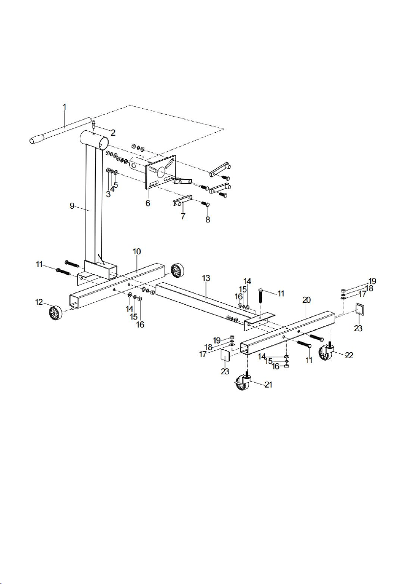
ASSEMBLY INSTRUCTIONS
1. Attach crossbeam(13) and
rear support axle
(10) to main post (9) with
bolt (11),
washer(14),
spring washer (15)and
Nut(16).
2. Attach
brake wheels
(21) to
anterior support axle
(20) with washer (17),
spring washer (18) and nut (19).Cover the end cover(23)at last.
3. Attach
anterior support axle
(20) to crossbeam(13)with bolt (11), washer
(14), spring washer (15) and nut (16).
4. Attach
mounting arms
(7) to
head assembly
(6) with bolt (8), washer (5),
spring washer (4) and nut (3).
5. Insert the head assembly (6) into the hole of the main post (9). Line up
the hole in the head assembly (6) and the main post (9), and assembly
them by inserting the lock pin (2).
6. Insert the handle assembly(6) into the hole of the
head assembly
(6).
7. Tight all the screws.
ASSEMBLY DIAGRAM
Item
Name
Qty.
Item
Name
Qty.
1
Handle
1
13
Crossbeam
1
2
Lock pin
1
14
Washer M10
6
3
Nut M14
4
15
Spring Washer M10
6
4
Spring Washer M14
4
16
Nut M10
6
5
Washer M14
4
17
Washer M12
2
6
Head Assembly
1
18
Spring Washer M12
2
7
Mounting Arms
4
19
Nut M12
2
8
Hex Head Bolt M14x60mm
4
20
Anterior Support Axle
1
9
Main Post
1
21
Brake Wheels
1
10
Rear Support Axle
1
22
No Brake Wheels
1
11
Hex Head Bolt M10x70mm
6
23
End Cover
2
12
Wheel
2
- 7 -

- 8 -
Importer: WAITCHX
Address: 250 bis boulevard Saint-Germain 75007 Paris
Importer: FREE MOOD LTD
Address: 2 Holywell Lane, London, England, EC2A 3ET
REP
UK
EUREP UK LTD
UNIT 2264, 100 OCK STREET, ABINGDON
OXFORDSHIRE ENGLAND OX14 5DH
REP
EC
EUREP GmbH
Unterlettenweg 1a, 85051
Ingolstadt, Germany
Manufacturer: Haiyan Xinxing Mechanical And Electrical. Co., Ltd
Address:Liuzhuang Village Xitang qiao Street Haiyan County Zhejiang
Province
Made In China